

Page 1

ThinkServerTS450
UserGuideandHardwareMaintenance
Manual
MachineTypes:70LY,70M0,70M1,and70M2
Page 2

Welcome
Beforeusingyourserverandthisdocument,besuretoreadtheReadMeFirstthatcomeswithyourserver.
Lenovomakesconstantimprovementonthedocumentationofyourserver.Togetallthelatestdocuments,
goto:
http://www.lenovo.com/UserManuals
Note:Yourservermightlookslightlydifferentfromillustrationsinthisdocument.Toshowthemainparts
clearly,someoftheillustrationsdonotshowallcomponents.
FourthEdition(August2016)
©CopyrightLenovo2015,2016.
LIMITEDANDRESTRICTEDRIGHTSNOTICE:IfdataorsoftwareisdeliveredpursuanttoaGeneralServices
Administration“GSA”contract,use,reproduction,ordisclosureissubjecttorestrictionssetforthinContractNo.
GS-35F-05925.
Page 3

Contents
Readthisfirst:safetyinformation..iii
Productsthatarenotassessed.........x
Safetyinspectionguide............x
Groundingrequirements............xi
Chapter1.Generalinformation.....1
Introduction.................1
Serverdocumentation.............2
Chapter2.Serversetuproadmap...5
Serversetupprocedure............5
Turningontheserver.............5
Turningofftheserver.............5
Chapter3.Productoverview......7
Inthebox.................7
Featuresandspecificationsofyourserver.....7
Operatingenvironment...........10
Softwareprograms.............10
ThinkServerEasyStartup.........10
ThinkServerEasyUpdateFirmwareUpdater.10
LenovoThinkServerPowerPlanner.....11
LenovoThinkServerDiagnostics......11
LenovoToolsCenterSuiteCLI.......11
Componentlocations............11
Machinetype,model,andserialnumber
label.................11
Frontviewoftheserver.........13
Frontpanel..............14
Rearviewoftheserver.........15
Serverlocks..............17
Servercomponents...........19
Hot-swapdriveactivityandstatusLEDs...21
Powerconversionboard.........22
Powerdistributionboard.........23
Hot-swappowersupplystatusLEDs....24
RAIDcard...............24
LenovoThinkServerSAS12GExpanderPCIe
Card.................26
Backplane..............27
Systemboardcomponents........30
Chapter4.Configuringtheserver..35
UsingtheSetupUtilityprogram........35
StartingtheSetupUtilityprogram.....35
SetupUtilityprograminterface......35
Usingpasswords............38
ConfiguringtheTPMfunction.......40
Selectingastartupdevice........40
ExitingtheSetupUtilityprogram......40
UpdatingtheBIOS...........40
ConfiguringtheEthernetcontrollers....41
UsingtheThinkServerEasyStartupprogram.41
ConfiguringRAID..............44
AboutRAID..............44
RAIDforyourserver...........45
ConfiguringonboardSATAsoftwareRAID..46
ConfiguringadvancedSATAorSAShardware
RAID.................48
Chapter5.Replacinghardware....51
PurchasingThinkServeroptions........51
Gettingfamiliarwithimportantguidelines....51
Precautions..............51
Handlingstatic-sensitivedevices.....52
Systemreliabilityguidelines........52
Workinginsidetheserverwiththepoweron.53
Preparingyourserverinadvanceandremovingthe
servercover................53
Removingandinstallinghardware.......54
Frontbezel..............55
Memorymodule............56
PCIecard...............58
Opticaldrive..............60
Non-hot-swapdrive...........66
Tapedrive...............69
Solid-statedrive(2.5-inch)........72
Hot-swapdrive.............75
Hot-swappowersupply.........78
Powerconversionboard.........81
Backplane..............83
Non-hot-swappowersupply.......88
Intrusionswitch............90
Frontpanelboardassembly........91
Frontsystemfan............93
Rearsystemfan............95
Heatsinkandfanassembly........97
Securedigitalmodule..........99
ThinkServerRAIDSuperCapacitorModule..102
ThunderboltMemoryModule.......105
LenovoThinkServerRAID520iupgrade
key.................106
CPU.................108
Coin-cellbattery............110
©CopyrightLenovo2015,2016
i
Page 4

Powerdistributionboard.........112
Forservicetechnicianonly:replacingthe
systemboard.............115
Completingthepartsreplacement.......118
Chapter6.Troubleshootingand
diagnostics.............121
Troubleshootingprocedure..........121
ViewingthestatusanddiagnosticLEDs.....121
Basictroubleshootingtables.........121
ThinkServerEasyStartupprogram
problems...............122
Opticaldriveproblems..........122
Storagedriveproblems.........123
Memorymoduleproblems........124
USBdeviceproblems..........124
Chapter7.Gettinginformation,help,
andservice.............125
Informationresources............125
Usingthedocumentation.........125
ThinkServerWebsite..........125
LenovoSupportWebsite.........125
Helpandservice..............125
Beforeyoucall.............125
Callingforservice............126
Usingotherservices..........126
Purchasingadditionalservices......127
AppendixA.Regulatory
information.............129
Exportclassificationnotice..........129
Electronicemissionnotices..........129
FederalCommunicationsCommission(FCC)
Statement...............129
JapanVCCIClassAcompliancestatement..131
Japanesestatementforacpowerconsumption
forJEITAharmonicsguideline.......131
Japanesestatementofcompliancefor
productslessthanorequalto20Aperphase
forJEITAharmonicsguideline.......132
Eurasiancompliancemark..........132
AppendixB.WEEEandrecycling
information.............133
ImportantWEEEinformation.........133
RecyclinginformationforBrazil........134
RecyclinginformationforJapan........134
BatteryrecyclinginformationforT aiwan.....134
BatteryrecyclinginformationfortheEuropean
Union..................135
BatteryrecyclinginformationfortheUnitedStates
andCanada................136
Requirementforbatteriescontaining
perchlorate................136
AppendixC.RestrictionofHazardous
Substances(RoHS)Directive....137
EuropeanUnionRoHS...........137
TurkishRoHS...............137
UkraineRoHS...............137
IndiaRoHS................137
ChinaRoHS................138
TaiwanBSMIRoHSdeclaration........139
AppendixD.Additional
statements.............141
Importantnotes..............141
Particulatecontamination..........141
GermanOrdinanceforWorkglossstatement...142
AppendixE.Notices.........143
Trademarks................144
AppendixF .Abbreviationsand
acronyms..............145
Index.................147
iiThinkServerTS450UserGuideandHardwareMaintenanceManual
Page 5
Readthisfirst:safetyinformation
ﺓء ﺍﺮ ﻗ ﻦ ﻣ ﺪ ﻛ ﺄﺗ ،ﺞ ﺘﻨﻤ ﻟﺍ ﻡ ﺍﺪ ﺨ ﺘﺳ ﺍ ﻞ ﺒﻗSa fet y Informa ! on
)ﺔ ﻣ ﻼ ﺴ ﻟﺍ ﺕ ﺎﻣ ﻮ ﻠﻌ ﻣ ( ﻊ ﻗﻮ ﻣ ﻲ ﻓ ﺎﻬ ﻤ ﻬ ﻓﻭ ﺕ ﺎﻐ ﻠﻟﺍ ﺓﺩ ﺪ ﻌ ﺘﻤ ﻟﺍ
Le no vo
ﺐ ﻳﻮ ﻟﺍ ﻰ ﻠﻋ.
ר צ ומ ב ש ומ יש ה ינ פ ל, ך מ ס מ ה ת א ןיב ה ל ו א ור ק ל ו ד יפ ק הSa fet y Informa ! on
)
ת וח יט ב א ש ונ ב ע ד ימ
(
ת ופ ש ב ע יפ ומ ה
ל ש ט נר ט ניא ה ר ת א ב ת וב רLeno vo.
Note:Beforeusingtheproduct,besuretoreadandunderstandthemultilingualSafetyInformationonthe
LenovoWebsiteat:
https://support.lenovo.com/documents/LNVO-DOCS
Antesdeusaroproduto,certifique-sedelereentenderasSafetyInformation(Informaçõessobresegurança)
multilínguesnositedaLenovo.
Предидаизползватепродукта,прочететеиразберетемногоезичнатаSafetyInformation(Информация
забезопасност)науебсайтанаLenovo.
PrijekorištenjanašegproizvodasvakakosrazumijevanjempročitajtevišejezičnidokumentSafetyInformation
(Informacijeosigurnosti)naweb-mjestutvrtkeLenovo.
PředpoužitímtohotoproduktusinezapomeňtepřečístvícejazyčnýdokumentSafetyInformation
(Bezpečnostníinformace)nawebuspolečnostiLenovo.
Førdubrugerproduktet,skaldusørgeforatlæseogforståSafetyInformation(sikkerhedsforskrifter),
derfindespåfleresprog,påLenovoswebsted.
LuemonikielinenSafetyInformation(Turvaohjeet)-julkaisuLenovonverkkosivustostaennentuotteenkäyttöä.
Avantd'utiliserceproduit,prenezconnaissancedesSafetyInformation(Informationsrelativesàlasécurité)
multilinguessurlesiteWebLenovo.
Πρινχρησιμοποιήσετετοπροϊόν,φροντίστεναδιαβάσετεκαινακατανοήσετετιςSafetyInformation
(Πληροφορίεςασφαλείας)στοδικτυακότόποτηςLenovo.
VorVerwendungdesProduktssolltenSiediemehrsprachigenSafetyInformation(Sicherheitsinformationen)
aufderLenovoWebsitelesenundverstehen.
Atermékhasználataelőttolvassaát,ésismerjemegaLenovowebhelyéntöbbnyelveniselérhetőSafety
Information(Biztonságitájékoztató)címűdokumentumot.
Primadiutilizzareilprodotto,accertarsidileggereecomprendereladocumentazionemultilinguaSafety
Information(Informazionisullasicurezza)sulsitoWebLenovo.
製品をご使用になる前に、LenovoWebサイトに掲載されているマルチリンガルのSafetyInformation(安全
上の注意)を読んで理解してください。
제품을사용하기전에Lenovo웹사이트의다국어SafetyInformation(안전정보)를주의깊게읽어
보십시오.
ZorgdatualleSafetyInformation(veiligheidsvoorschriften)opdewebsitevanLenovohebtgelezenen
begrepenvoordatuhetproductgebruikt.
©CopyrightLenovo2015,2016
iii
Page 6
PrzedskorzystaniemzproduktunależyzapoznaćsięzwielojęzycznymdokumentemSafetyInformation
ก
่
ีน์ฑณัภติลผ้ชในอ
้
โ ป ร ด อ
่
กจใา้ขเมาวคาํทะลแนา
ั
บ
Sa fety Informa ! on
( ยัภดอลปมาวคลูมอ้ข ) ห ล า ย ภ าษ า
์ตซไบ็วเนบ
Lenovo
(Informacjedotyczącebezpieczeństwa),dostępnymwserwisieinternetowymLenovo.
Antesdeutilizaroproduto,certifique-sedequelêecompreendeadocumentaçãomultilingueSafety
Information(InformaçõessobreSegurança)nosítiodaWebdaLenovo.
Înaintedeautilizaprodusul,citiţişiînţelegeţiSafetyInformation(informaţiiledesiguranţă)înmaimulte
limbidepesite-ulwebLenovo.
Førdubrukerproduktet,måduleseogforstådenflerspråkligeSafetyInformation(sikkerhetsinformasjonen)
pånettstedettilLenovo.
ПередиспользованиемпродуктаобязательноознакомьтесьсразделомSafetyInformation
(Информацияпотехникебезопасности),представленнымнанесколькихязыкахнавеб-сайтеLenovo.
在使用产品之前,请务必先阅读和了解LenovoWeb站点上的多语言SafetyInformation《安全信息》。
Prekorišćenjaproizvoda,obaveznopažljivoisarazumevanjempročitajtevišejezičneSafetyInformation
(Bezbednosneinformacije)naveblokacijikompanijeLenovo.
Skôrnežproduktzačnetepoužívať,prečítajtesiviacjazyčnéSafetyInformation(Bezpečnostnéinformácie)na
webovejlokalitespoločnostiLenovo.
Preduporaboizdelkaposkrbite,dabosteprebraliinrazumelirazdelekSafetyInformation(Varnostne
informacije),kijenaspletnemmestuLenovonavoljovvečjezikih.
Antesdeusarelproducto,asegúresedeleeryentenderlasecciónSafetyInformation(Informaciónde
seguridad)multilingüedelsitiowebdeLenovo.
InnanduanvänderdenhärproduktenärdetviktigtattduharlästochförståttdenflerspråkigaSafety
Information(säkerhetsinformationen)påLenovoswebbplats.
使用本產品之前,請務必先閱讀及瞭解Lenovo網站上多國語言版本的SafetyInformation(安全資訊)。
Ürünükullanmadanönce,LenovowebsitesindekiSafetyInformation(GüvenlikBilgileri)belgesini(birdençok
dildeyayınlanmaktadır)mutlakaokuyun.
Першніжвикористовуватипродукт ,обов'язковопрочитайтеSafetyInformation(інструкціїзтехніки
безпеки),доступнірізнимимоваминавеб-сайтіLenovo.
Important:Ensurethatyoureadandunderstandallcautionanddangerstatementsinthisdocumentbefore
youperformtheprocedures.Readandunderstandanyadditionalsafetyinformationthatisincludedwiththe
serveroroptionaldevicebeforeyouinstall,remove,orreplacethedevice.
ivThinkServerTS450UserGuideandHardwareMaintenanceManual
Page 7
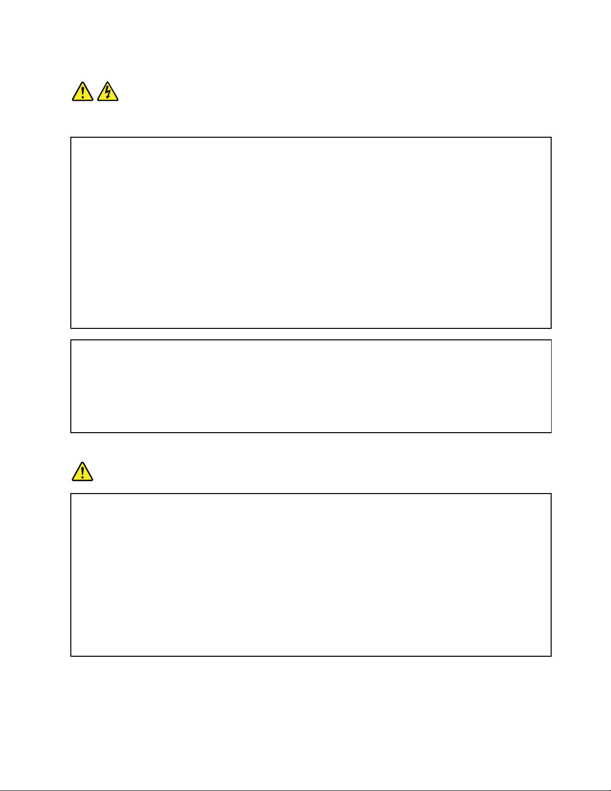
Statement1
DANGER
Electricalcurrentfrompower,telephone,andcommunicationcablesishazardous.
Toavoidashockhazard:
•Donotconnectordisconnectanycablesorperforminstallation,maintenance,orreconfigurationofthis
productduringanelectricalstorm.
•Connectallpowercordstoaproperlywiredandgroundedelectricaloutlet.
•Ensurethatallpowercordconnectorsaresecurelyandcompletelypluggedintoreceptacles.
•Connecttoproperlywiredoutletsanyequipmentthatwillbeattachedtothisproduct.
•Whenpossible,useonehandonlytoconnectordisconnectsignalcables.
•Neverturnonanyequipmentwhenthereisevidenceoffire,water,orstructuraldamage.
•Disconnecttheattachedpowercords,telecommunicationssystems,networks,andmodemsbeforeyou
openthedevicecovers,unlessinstructedotherwiseintheinstallationandconfigurationprocedures.
•Connectanddisconnectcablesasdescribedinthefollowingtablewheninstalling,moving,oropening
coversonthisproductorattacheddevices.
Toconnect:Todisconnect:
1.TurneverythingOFF .
2.First,attachallcablestodevices.
3.Attachsignalcablestoconnectors.
4.Attachpowercordstooutlets.
5.TurndevicesON.
1.TurneverythingOFF .
2.First,removepowercordsfromoutlets.
3.Removesignalcablesfromconnectors.
4.Removeallcablesfromdevices.
Statement2
DANGER
Dangerofexplosionifbatteryisincorrectlyreplaced.
Whenreplacingthelithiumcoincellbattery,useonlythesameoranequivalenttypethatis
recommendedbythemanufacturer .Thebatterycontainslithiumandcanexplodeifnotproperly
used,handled,ordisposedof.
Donot:
•Throworimmerseintowater
•Heattomorethan100°C(212°F)
•Repairordisassemble
Disposeofthebatteryasrequiredbylocalordinancesorregulations.
©CopyrightLenovo2015,2016
v
Page 8
Statement3
CAUTION:
Whenlaserproducts(suchasCD-ROMs,DVDdrives,fiberopticdevices,ortransmitters)are
installed,notethefollowing:
•Donotremovethecovers.Removingthecoversofthelaserproductcouldresultinexposureto
hazardouslaserradiation.Therearenoserviceablepartsinsidethedevice.
•Useofcontrolsoradjustmentsorperformanceofproceduresotherthanthosespecifiedherein
mightresultinhazardousradiationexposure.
DANGER
SomelaserproductscontainanembeddedClass3AorClass3Blaserdiode.Notethefollowing:
Laserradiationwhenopen.Donotstareintothebeam,donotviewdirectlywithoptical
instruments,andavoiddirectexposuretothebeam.
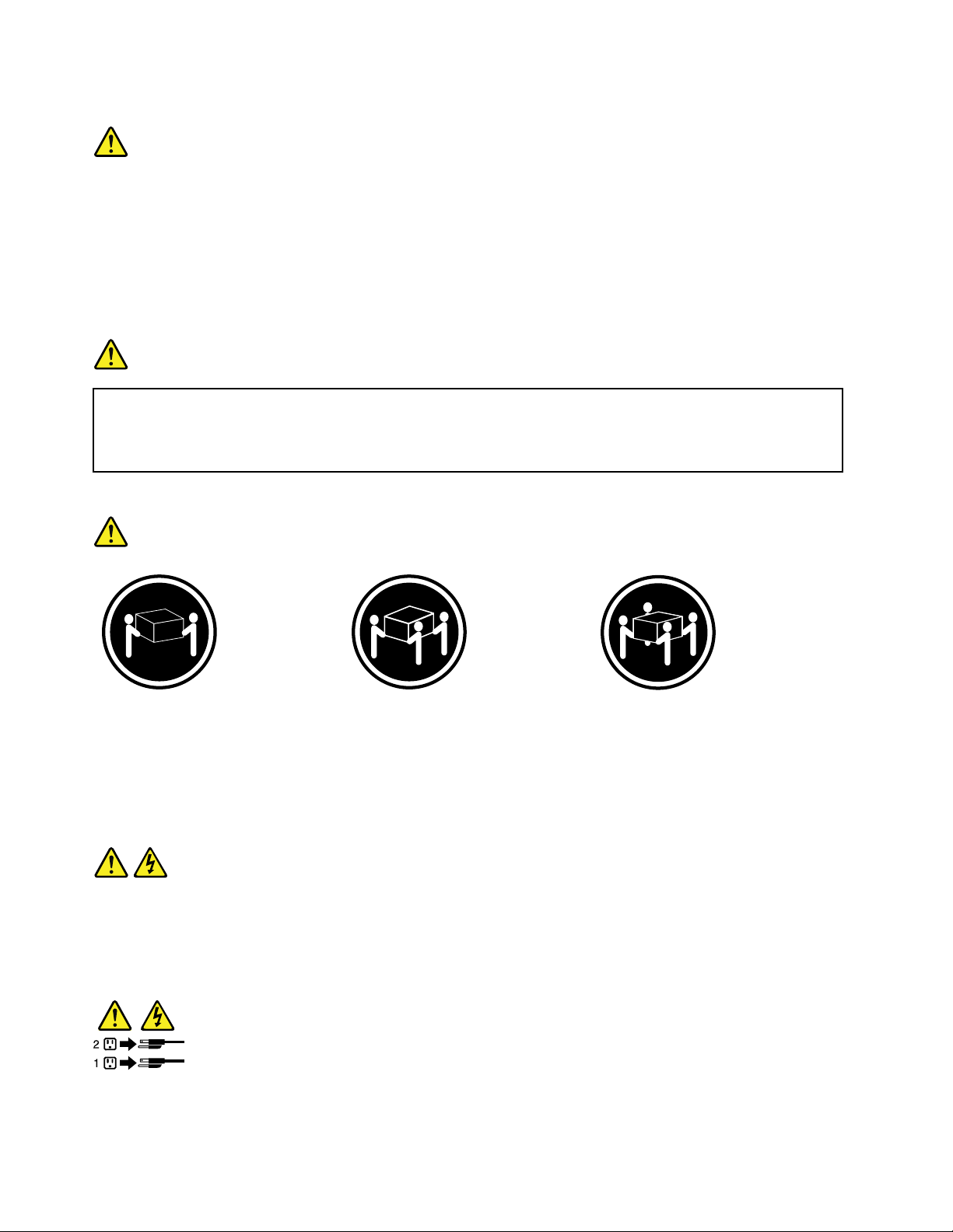
Statement4
≥18kg(39.7lb)≥32kg(70.5lb)≥55kg(121.2lb)
<32kg(70.5lb)<55kg(121.2lb)<100kg(220.5lb)
CAUTION:
Usesafepracticeswhenlifting.
Statement5
CAUTION:
Thepowercontrolbuttononthedeviceandthepowerswitchonthepowersupplydonotturnoff
theelectricalcurrentsuppliedtothedevice.Thedevicealsomighthavemorethanonepower
cord.Toremoveallelectricalcurrentfromthedevice,ensurethatallpowercordsaredisconnected
fromthepowersource.
viThinkServerTS450UserGuideandHardwareMaintenanceManual
Page 9
Statement6
CAUTION:
Ifyouinstallastrain-reliefbracketoptionovertheendofthepowercordthatisconnectedtothe
device,youmustconnecttheotherendofthepowercordtoapowersourcethatiseasilyaccessible
incaseitneedstobedisconnected.
Statement7
CAUTION:
Ifthedevicehasdoors,ensurethatyouremoveorsecurethedoorsbeforemovingorliftingthe
devicetoprotectagainstpersonalinjury.Thedoorswillnotsupporttheweightofthedevice.
Statement8
CAUTION:
Neverremovethecoveronapowersupplyoranypartthathasthefollowinglabelattached.
Hazardousvoltage,current,andenergylevelsarepresentinsideanycomponentthathasthislabel
attached.Therearenoserviceablepartsinsidethesecomponents.Ifyoususpectaproblemwith
oneoftheseparts,contactaservicetechnician.
Statement9
CAUTION:
Disconnectthehot-swapfancablesbeforeremovingthefanfromthedevicetoprotectagainst
personalinjury.
Statement10
CAUTION:
Thefollowinglabelindicatesasharp-edgehazard.
©CopyrightLenovo2015,2016
vii
Page 10

Statement11
CAUTION:
Thefollowinglabelindicatesapotentialheathazard.
Statement12
DANGER
Overloadingabranchcircuitisapotentialfirehazardandashockhazardundercertainconditions.T o
avoidthesehazards,ensurethatyoursystemelectricalrequirementsdonotexceedbranchcurrentratings
attheinstallationsite.
Statement13
CAUTION:
Ensurethattherackissecuredproperlytoavoidtippingwhentheserverunitisextendedontherails.
Statement14
CAUTION:
SomeaccessoryoroptionboardoutputsexceedClass2orlimitedpowersourcelimits.You
mustinstalltheappropriateinterconnectingcablinginaccordancewithyourlocalelectricalcode
requirements.
Statement15
CAUTION:
Thepower-controlbuttononthedevicemayputthedeviceinstandbymodeinsteadofturningoff
thedevice.Inaddition,thedevicemighthavemultipleconnectionstodcpower.Toremoveall
electricalcurrentfromthedevice,ensurethatallconnectionstodcpoweraredisconnectedat
thedcpowerinputterminals.
viiiThinkServerTS450UserGuideandHardwareMaintenanceManual
Page 11
Statement16
CAUTION:
Toreducetheriskofelectricshockorenergyhazards:
•Thisequipmentmustbeinstalledbytrainedservicepersonnelinarestricted-accesslocation,as
definedbyyourlocalelectricalcodeandthelatesteditionofIEC60950.
•Thebranchcircuitovercurrentprotectionmustberatedinaccordancewithlocalelectricalcode
requirements.
•Use1.3mm
2
or16AmericanWireGauge(AWG)copperconductoronly,notexceeding3meters
inlength.
•Torquethewiring-terminalscrewsto1.4newton-metersor12inch-pounds.
•Provideareadilyavailable,approvedandrateddisconnectdeviceinthefieldwiring.
Statement17
CAUTION:
ThisproductcontainsaClass1Mlaser.Donotviewdirectlywithopticalinstruments.
Statement18
CAUTION:
Donotplaceanyobjectontopofrack-mountedproducts.
Statement19
CAUTION:
Hazardousmovingparts.Keepfingersandotherbodypartsaway.
©CopyrightLenovo2015,2016
ix
Page 12

Statement20
CAUTION:
Alithiumionbatteryisprovided.T oavoidpossibleexplosion,donotburnthebattery.Replacethe
batteryonlywiththeLenovo-approvedpart.Recycleordiscardthebatteryasinstructedbylocal
regulations.
Productsthatarenotassessed
Typicalproductsthatarenotassessedincludebutnotlimitedtothefollowing:
•ServerandIT -rackcomponents(forexample,uninterruptiblepowersuppliesandcurrentdistribution
systems)
•DevicesinITrooms(forexample,bulkstorageunitsandnetworkproducts)
•Industriallow-voltageswitchgear
Safetyinspectionguide
Thepurposeofthisinspectionguideistoassistyouinidentifyingpotentiallyunsafeconditions.Aseach
machinewasdesignedandbuilt,requiredsafetyitemswereinstalledtoprotectusersandservicetechnicians
frominjury.Thisguideaddressesonlythoseitems.Youshouldusegoodjudgmenttoidentifypotentialsafety
hazardsduetoattachmentofnon-ThinkServerfeaturesoroptionsnotcoveredbythisinspectionguide.
Ifanyunsafeconditionsarepresent,youmustdeterminehowserioustheapparenthazardcouldbeand
whetheryoucancontinuewithoutfirstcorrectingtheproblem.
Considertheseconditionsandthesafetyhazardstheypresent:
•Electricalhazards,especiallyprimarypower(primaryvoltageontheframecancauseseriousorfatal
electricalshock)
•Explosivehazards,suchasadamagedCathodeRayTube(CRT)monitororabulgingcapacitor
•Mechanicalhazards,suchaslooseormissinghardware
Todeterminewhetherthereareanypotentiallyunsafeconditions,usethefollowingchecklistatthebeginning
ofeveryservicetask.Beginthecheckswiththepoweroff,andthepowercordsdisconnected.
Checklist:
1.Checkexteriorcoversfordamage(loose,broken,orsharpedges).
2.Powerofftheserver.Disconnectthepowercords.
3.Checkthepowercordfor:
a.Athird-wiregroundconnectoringoodcondition.Useametertomeasurethird-wireground
continuityfor0.1ohmorlessbetweentheexternalgroundpinandtheframeground.
b.Thepowercordshouldbetheauthorizedtypespecifiedforyourserver.Goto:
http://www.lenovo.com/serviceparts-lookup
c.Insulationmustnotbefrayedorworn.
4.Checkforcrackedorbulgingbatteries.
5.Removethecover.
6.Checkforanyobviousnon-ThinkServeralterations.Usegoodjudgmentastothesafetyofany
non-ThinkServeralterations.
xThinkServerTS450UserGuideandHardwareMaintenanceManual
Page 13

7.Checkinsidetheunitforanyobviousunsafeconditions,suchasmetalfilings,contamination,wateror
otherliquids,orsignsoffireorsmokedamage.
8.Checkforworn,frayed,orpinchedcables.
9.Checkthatthepower-supplycoverfasteners(screwsorrivets)havenotbeenremovedortamperedwith.
Groundingrequirements
Electricalgroundingoftheserverisrequiredforoperatorsafetyandcorrectsystemfunction.Proper
groundingoftheelectricaloutletcanbeverifiedbyacertifiedelectrician.
©CopyrightLenovo2015,2016
xi
Page 14

xiiThinkServerTS450UserGuideandHardwareMaintenanceManual
Page 15

Chapter1.Generalinformation
Thischaptercontainsthefollowingitems:
•“Introduction”onpage1
•“Serverdocumentation”onpage2
Introduction
Thefollowingtablelistsimportantinformationaboutyourserverandwheretoobtaintheinformation.
InformationWheretoobtain
LenovoLimitedWarranty
(LLW)
WorldwideLenovoSupport
telephonelist
Mostup-to-dateinformation
abouttheserver
Latesttechnicalinformation
Instructionsonhowto
registeryourserverwith
Lenovo
Productinformationlabel
TheLLWcontainsthewarrantytermsthatapplytotheproductyoupurchasedfrom
®
Lenovo
http://www.lenovo.com/warranty/llw_02
IfyoucannotobtaintheLLWfromtheLenovoWebsite,contactyourlocalLenovo
officeorresellertoobtainaprintedversionoftheLLW,freeofcharge.
Telephonenumbersaresubjecttochangewithoutnotice.Themostup-to-date
telephonelistforLenovoSupportisalwaysavailableat:
http://www.lenovo.com/support/phone
Ifthetelephonenumberforyourcountryorregionisnotlisted,contactyourLenovo
resellerorLenovomarketingrepresentative.
http://www.lenovo.com/thinkserver
http://www.lenovo.com/support
Followtheinstructionsat:
http://www.lenovo.com/register
Whenyouregisteryourserver,informationisenteredintoadatabase,whichenables
Lenovotocontactyouincaseofarecallorothersevereproblem.Afteryouregister
yourserverwithLenovo,youwillreceivequickerservicewhenyoucallLenovo
forhelp.Inaddition,somelocationsofferextendedprivilegesandservicesto
registeredusers.
Recordinformationaboutyourserverinthefollowingtable.Youwillneedthe
informationifyoueverneedtohaveyourserverserviced.Theproductinformation
labelisattachedonthechassis.See“Machinetype,model,andserialnumber
label”onpage11
.TheLLWisavailableat:
.
Productname
Machinetypeandmodel(MT-M)
Serialnumber(S/N)
Dateofpurchase
©CopyrightLenovo2015,2016
______________________________________________
______________________________________________
______________________________________________
______________________________________________
1
Page 16

Serverdocumentation
Thistopicprovidesageneraldescriptionofeachdocumentforyourserverandinstructionsonhow
toobtainallthedocuments.
Printeddocuments
Yourserverpackagecontainsthefollowingprinteddocuments:
•ReadMeFirst
Thisisamultilingualdocument.Itillustratessafetysymbolsandinstructsyoutoreadthecomplete
safety,warranty,andsupportinformationprovidedontheLenovoWebsitebeforeusingtheserver.This
documentalsotellsyouhowtofindthemostup-to-dateinformationontheLenovoSupportWebsite.In
addition,recycling,environmental,andlegalnoticesareallincluded.
•Alettertocustomers
Thisisamultilinguallettertocustomers,whichtellscustomersthatLenovoisundertakingapaperless
electronicdocumentationinitiativetoprotectenvironment.Thisletteralsoprovidesinformationabout
howtocontactLenovoifyourequireaprintedversionofanyelectronicdocuments.
Electronicdocuments
•Youcanfindthefollowingelectronicdocumentsathttps://support.lenovo.com/documents/LNVO-DOCS:
–SafetyInformation
Thisisamultilingualdocumentthatincludesallthesafetystatementsforyourproduct.Ensurethatyou
readandunderstandthesesafetystatementsbeforeusingtheproduct.
–LenovoLimitedWarranty
ThisdocumentincludestheLenovotermsandwarrantystatements.
–LenovoLicenseAgreement
ThisdocumentincludesthetermsandconditionsoftheLenovoLicenseAgreement.
•YoucanfindthefollowingelectronicdocumentsfromtheLenovoSupportWebsite.Goto
http://www.lenovo.com/support,clickDocumentation,andfollowtheinstructionsonthescreento
findthedocumentyouneed.
–Safety,Warranty,andSupportInformation
Thisisamultilingualdocumentthatincludesallthesafetystatementsforyourproductinmorethan30
languages.Ensurethatyoureadandunderstandallthesafetystatementsbeforeusingtheproduct.
ThisdocumentalsoincludestheLenovowarrantystatement,CustomerReplaceableUnits(CRUs)
information,andinformationabouthowtocontacttheLenovoCustomerSupportCenter.
–UserGuideandHardwareMaintenanceManual
Thisdocumentprovidesdetailedinformationtohelpyougetfamiliarwithyourserverandhelpyouuse,
configure,andmaintainyourserver.
–MegaRAIDSASSoftwareUserGuide(Englishonly)
ThisdocumentprovidesinformationaboutRedundantArrayofIndependentDisks(RAID)andhowto
usetheutilityprogramstoconfigure,monitor,andmaintainyourserverRAIDandrelateddevices.
Note:RefertothisdocumentforhardwareRAIDinformationiftheserverhasarequiredRAIDcard
installed.SeeRAIDcard.ForinformationaboutonboardsoftwareRAID,seeConfiguringonboard
SATAsoftwareRAID.
2ThinkServerTS450UserGuideandHardwareMaintenanceManual
Page 17

–Otherdocuments
YoumightfindotherdocumentsfortheHostBusAdapter(HBA),Ethernetcard,orotheroptionalparts.
Chapter1.Generalinformation3
Page 18

4ThinkServerTS450UserGuideandHardwareMaintenanceManual
Page 19

Chapter2.Serversetuproadmap
Thischapterprovidesageneralroadmaptoguideyouthroughsettingupyourserver.
Theserversetupprocedurevariesdependingontheconfigurationoftheserverwhenitwasdelivered.In
somecases,theserverisfullyconfiguredandyoujustconnecttheservertothenetworkandanacpower
source,andthenyoucanturnontheserver.Inothercases,theserverneedstohavehardwarefeatures
installed,requireshardwareandfirmwareconfiguration,andrequiresanoperatingsystemtobeinstalled.
Serversetupprocedure
Thefollowinglistisageneralprocedureforsettingupyourserver:
1.Unpacktheserverpackage.See“Inthebox”onpage7.
2.Installanyrequiredhardwareorserveroption.SeetherelatedtopicinChapter5“Replacinghardware”
onpage51
3.ConnecttheEthernetcableandpowercordstotheserver.See“Rearviewoftheserver”onpage
tolocatetheconnectors.
15
4.Turnontheservertoverifyoperation.See“Turningontheserver”onpage5.
5.ReviewtheUnifiedExtensibleFirmwareInterface(UEFI)BasicInputOutputSystem(BIOS)settingsand
customizeasneeded.See“UsingtheSetupUtilityprogram”onpage35.
6.ConfigureRAIDandinstalltheoperatingsystemandbasicdrivers.See“UsingtheThinkServer
EasyStartupprogram”onpage41and“ConfiguringRAID”onpage44.
7.Installanyadditionaldriversneededforaddedfeatures.Refertotheinstructionsthatcomewiththe
hardwareoption.
8.ConfigureEthernetsettingsintheoperatingsystembyreferringtotheoperatingsystemhelp.Youcan
skipthisstepiftheoperatingsystemwasinstalledusingtheThinkServerEasyStartupprogram.
9.Checkforfirmwareupdates.Toupdatethefirmware,dooneofthefollowing:
.
•Gotohttp://www.lenovo.com/driversandfollowtheinstructionsontheWebpagetocheckforthe
latestleveloffirmware,suchastheBIOSupdatesanddevicedrivers.
•UsetheFirmwareUpdaterprogram.
10.Installotherapplications.Refertothedocumentationthatcomeswiththeapplicationsthatyouwantto
install.
Turningontheserver
Afteryoufinishunpackingandsettinguptheserver,connectittoanacpowersource.Pressthepower
buttononthefrontpaneltoturnontheserver.See“Frontpanel”onpage14.
Turningofftheserver
CAUTION:
Thepowercontrolbuttononthedeviceandthepowerswitchonthepowersupplydonotturnoff
theelectricalcurrentsuppliedtothedevice.Thedevicealsomighthavemorethanonepower
cord.Toremoveallelectricalcurrentfromthedevice,ensurethatallpowercordsaredisconnected
fromthepowersource.
©CopyrightLenovo2015,2016
5
Page 20
Theservercanbeturnedoffinoneofthefollowingways:
•Turnofftheserverfromtheoperatingsystemifyouroperatingsystemsupportsthisfeature.Afteran
orderlyshutdownoftheoperatingsystem,theserverturnsoffautomatically.Forinstructionsonhow
toshutdownyourspecificoperatingsystem,refertotherelateddocumentationorhelpsystemfor
theoperatingsystem.
•Pressthepowerbuttononthefrontpaneltostartanorderlyshutdownoftheoperatingsystemandturn
offtheserver,ifyouroperatingsystemsupportsthisfeature.
•Ifyourserverstopsrespondingandyoucannotturnitoff,pressandholdthepowerbuttononthe
frontpanelforfoursecondsormore.Ifyoustillcannotturnofftheserver,disconnectallpowercords
fromtheserver.
•Theservermightturnoffasanautomaticresponsetoacriticalsystemfailure.
6ThinkServerTS450UserGuideandHardwareMaintenanceManual
Page 21

Chapter3.Productoverview
Thischaptercontainsthefollowingitems:
•“Inthebox”onpage7
•“Featuresandspecificationsofyourserver”onpage7
•“Operatingenvironment”onpage10
•“Softwareprograms”onpage10
•“Componentlocations”onpage11
Inthebox
Yourshippingboxcontainsthefollowingitems:
•Server
•Materialbox,includingitemssuchaspowercords(availableonsomemodels)andprinteddocumentation
Featuresandspecificationsofyourserver
Thistopicliststhefeaturesandspecificationsofyourserver,suchasdimensionandweight;hardware
configurations;andreliability,availability,andserviceability(RAS)features.TheRASfeaturesinclude
securityfeatures,basicsystemmanagementfeatures,andadvancedsystemmanagementfeatures.The
RASfeatureshelpyoutoensuretheintegrityofthedatastoredontheserver,theavailabilityoftheserver
whenyouneedit,andtheeasewithwhichyoucandiagnoseandcorrectproblems.
Dimensionandweight
ElectricalinputUniversalinput:
CentralProcessingUnit(CPU)YourservercomeswithoneofthefollowingCPUs(internalcachesizevaries
Memory
•Width:173mm(6.81inches)
•Height:430mm(16.93inches)withoutfootstands;443.5mm(17.46
inches)withfootstands
•Depth:566mm(22.28inches)includingthefrontbezel
•Weight
–Rangeofproductweightwithoutpackage:18–26.5kg(39.68–57.32lb)
–Maximumproductpackageweight:4.5kg(9.92lb)
Lowrange:100to127Vac
Highrange:200to240Vac
Inputfrequencyrange:50to60Hz
bymodel):
®
•Intel
•IntelCore
•IntelPentium
Yourserverhasfourmemoryslots.Formoreinformation,see“Memory
moduleinstallationrules”onpage56
®
Xeon
™
®
.
©CopyrightLenovo2015,2016
7
Page 22

Powersupply
Systemfans
InternaldrivesInternaldrivesaredevicesthatyourserverusestoreadandstoredata.The
Theservermightcomewithoneofthefollowingpowersupplyconfigurations:
•Onescrew-secured,non-hot-swap400-wattpowersupplyassembly
•Oneortwohot-swap450-wattredundantpowersupplies
Note:Ifyouareusinguninterruptiblepowersupplies(UPS),ensurethatyou
useonlypure-sineUPSwithyourThinkServerserver.
Yourservercomeswiththefollowingfanstoprovidepropersystemcooling
andairflow:
•Oneheatsinkandfanassembly
•Twofrontsystemfans
•Onerearsystemfan
internaldrivessupportedbyyourservervarybymodel.
•Internalstoragedrive
–Uptofour3.5-inchhot-swapSerialAdvancedTechnologyAttachment
(SATA)orSerialAttachedSCSI(SAS)harddiskdrives(HDDs)(SCSIis
theacronymforSmallComputerSystemInterface)
–Fivetoeight3.5-inchhot-swapSATAorSASHDDs
–Uptofour3.5-inchnon-hot-swapSATAHDDs
–Uptoeight2.5-inchhot-swapSA TAorSASHDDs
–Uptosixteen2.5-inchhot-swapSATAorSASHDDs
–Uptofour3.5-inchandeight2.5-inchhot-swapSATAorSASHDDs
•Opticaldrive
–Uptotwoopticaldrives
–Theserverhastwoopticaldrivebays.Theloweropticaldrivebayis
installedwithaSATAopticaldrive.
•Tapedrive(availableonsomemodels)
YourserversupportsRDXandLTOtapedrivesthatenableyoutostore
dataontapedrivemedia.Toinstallorremoveatapedrive,see“Installing
atapedrive”onpage70
.
Notes:
–Iftheserverhasonlyonetapedriveinstalled,ensurethattheoptical
driveisinstalledinthelowerbay(theopticaldrivebay1).
–IfyourserverisinstalledwithaWindowsServeroperatingsystem,you
canusetheWindowsBackupprogramtobackupthedatastoredon
tapedrivemedia.Fordetailedinformation,refertotheuserguideofthe
tapedrive.Theuserguideisavailablefordownloadat:
http://www.lenovo.com/UserManuals
Expansionslots
Yourserverhasfourexpansionslotsonthesystemboard.Fordetailed
information,see“Systemboardcomponents”onpage30.
8ThinkServerTS450UserGuideandHardwareMaintenanceManual
Page 23

Input/Output(I/O)features
•Frontpanel
–TwoUSB3.0connectors
•Rearpanel:
–VideoGraphicsArray(VGA)DB-15connector
–SixUSB3.0connectors
–RJ-45Ethernetconnector
–DisplayPort®connector
–Serialconnector
–Audioline-inconnector
–Audioline-outconnector
–Microphoneconnector
EthernetconnectivityThereisoneRJ-45Ethernetconnectorontherearpanelwith10megabits
persecond(Mbps),100Mbps,or1000Mbpsnetworkconnectivity.Formore
information,see“Rearviewoftheserver”onpage15.
Securityfeatures•Serverlocks(see“Serverlocks”onpage17)
•Administratorpasswordandpower-onpasswordtohelpprotect
unauthorizedaccesstotheserver(see“Usingpasswords”onpage38)
•ThinkServerTrustedPlatformModule(TPM),whichisasecuritychip,to
helpenhanceserversecurity
•Hot-swapredundantpowersuppliestohelpavoidsignificantinterruption
totheoperationofthesystemwhenapowersupplyfails(availableon
somemodels)
•Intrusionswitchthatinformsyouthroughaneventinthesystemeventlog
(SEL)whentheservercoverisnotproperlyinstalledorclosed
Basicsystemmanagementfeatures
•Abilitytostorethepower-onself-test(POST)hardwaretestresults
•BIOSSetupUtilityprogram
TheBIOSSetupUtilityprogramhelpsyouviewtheserverinformationand
configuretheserverinthepre-operatingsystemenvironment.See“Using
theSetupUtilityprogram”onpage35.
•Hot-swapfeature
Somemodelssupporthot-swapstoragedrivesandhot-swapredundant
powersupplies.Withthehot-swapfeature,youcaninstall,remove,or
replaceastoragedriveorafailingpowersupplywithoutturningoffthe
server.
•PrebootExecutionEnvironment(PXE)
TheIntelPXEtechnologyenablesyoutostartyourcomputers,loadan
operatingsystem,ordeployexecutableimagesfromaremoteserverby
usinganetworkinterface.Theoperationcanbedoneindependentlyof
localdatastoragedevices(suchasHDDs)orinstalledoperatingsystems.
•RedundantArrayofIndependentDisks(RAID)
YourserversupportsonboardSATAsoftwareRAID.IfarequiredRAID
cardisinstalled,yourserveralsosupportsadvancedSATA/SAShardware
RAIDconfigurations.Fordetailedinformation,see“ConfiguringRAID”
onpage44
.
•Statuslight-emittingdiodes(LEDs)anddiagnosticLEDs
FormoreinformationabouttheLEDsforyourserver,refertotherelated
topicsin“Componentlocations”onpage11
.
•Softwareprograms
Chapter3.Productoverview9
Page 24

Formoreinformationaboutthesoftwareprograms,see“Software
programs”onpage10.
Operatingenvironment
Thefollowingtableprovidesinformationabouttheoperatingenvironmentforyourserver.
Table1.Operatingenvironment
Airtemperature(operating)5°Cto35°C(41°Fto95°F)
Airtemperature(storage)-40°Cto60°C(-40°Fto140°F)inoriginalshippingpackage
Humidity(operating)8%to80%(non-condensing)
Humidity(storage)10%to90%(non-condensing)
Altitude
0to3048m(0to10000ft)inanunpressurizedenvironment
Softwareprograms
Thistopicprovidesinformationaboutthesoftwareprogramsthatyoucanusetosetup,use,andmaintain
theserver.
Todownloadthesoftwareprograms,gototheLenovoSupportWebsiteathttp://www.lenovo.com/support
andfollowtheinstructionsontheWebpage.
Fordetailedinformationaboutusingtheprogram,refertothehelpsystemoruserguideoftheprogram.
ThinkServerEasyStartup
TheThinkServerEasyStartupprogramsimplifiestheprocessofconfiguringRAIDandinstallingsupported
MicrosoftWindowsandLinuxoperatingsystemsanddevicedriversonyourserver.Thisprogramisprovided
withyourserveronaself-starting(bootable)ThinkServerEasyStartupDVD.Theuserguidefortheprogramis
alsoontheDVDandcanbeaccesseddirectlyfromtheprograminterface.Fordetailedinformation,see
“UsingtheThinkServerEasyStartupprogram”onpage41
.
ThinkServerEasyUpdateFirmwareUpdater
TheThinkServerEasyUpdateFirmwareUpdaterprogram(hereinafterreferredtoasFirmwareUpdater)
enablesyoutomaintainyourserverfirmwareuptodateandhelpsyouavoidunnecessaryserveroutages.
FirmwareUpdaterisprovidedontheLenovoSupportWebsite.
ToupdateyoursystemfirmwareusingFirmwareUpdater,dothefollowing:
Note:Beforedistributingfirmwareupdatestoaserver,ensurethatyourservercanrestartsuccessfully
withoutencounteringhardwareproblems.
1.Gotohttp://www.lenovo.com/driversandfollowtheinstructionsontheWebpagetolocateFirmware
Updater.
2.DownloadtheISOimageforFirmwareUpdaterandtheTXTfilethatcontainstheinstallationinstructions.
3.UseanyCDorDVDburningsoftwaretocreateabootablediscwiththeISOimage.
4.PrinttheTXTfileandfollowtheinstructionstouseFirmwareUpdatertoupdateyoursystemfirmware.
10ThinkServerTS450UserGuideandHardwareMaintenanceManual
Page 25

LenovoThinkServerPowerPlanner
TheLenovoThinkserverPowerPlannerprogramprovidesinformationaboutthepowerconsumptionand
electriccurrentcalculationbasedonthedifferentconfigurationsofserversandotherdevices.Theprogram
alsohelpstoplanserversanddevicesdeploymentinanefficientway.
FordetailedinformationaboutusingtheLenovoThinkServerPowerPlannerprogram,refertothehelp
systemoftheprogram.
LenovoThinkServerDiagnostics
TheLenovoThinkServerDiagnosticsprogramenablesyoutodiagnoseserverproblemsoffline,perform
somediagnostictests,andcollectsysteminformation.Examplesofthesysteminformationincludebasic
operating-systeminformation,hardwareinformation,SEL,RAIDlog,andsoon.Dependingonthemodel,
yourservermightcomewithoneofthefollowingdiagnosticprogrameditions:
•LenovoThinkServerDiagnosticsEmbeddedEdition
•LenovoThinkServerDiagnosticsStandaloneEdition
FormoreinformationaboutLenovoThinkServerDiagnostics,goto
http://support.lenovo.com/us/en/lenovodiagnosticsolutions/downloads.LocatetheLenovoThinkServer
DiagnosticssectionatthebottomoftheWebpage.Then,clickthedesiredlinkformoreinformation.
LenovoT oolsCenterSuiteCLI
LenovoToolsCenterSuiteCLIconsistsofindividualapplicationmodulesthatutilizeacommand-lineinterface
(CLI)tohelpyoumanageservers.Withtheinventoryapplicationmodule,LenovoToolsCenterSuiteCLI
enablesyoutogetinventoryandsysteminformationforThinkServerservers.
FormoreinformationaboutLenovoToolsCenterSuiteCLI,goto:
https://support.lenovo.com/solutions/HT116433?LinkTrack=Solr
Componentlocations
Thistopicprovidesinformationtohelpyoulocateyourservercomponents.
Machinetype,model,andserialnumberlabel
WhenyoucontactLenovoforhelp,themachinetype,model,andserialnumberinformationhelpssupport
technicianstoidentifyyourserverandprovidefasterservice.
Chapter3.Productoverview11
Page 26

Thefollowingillustrationisasampleofthemachinetype,model,andserialnumberlabelontheserver.
M
T-M X
X
XX
-
X
XX
S
/
N
X
XX
X
X
X
X
MT-M XXXX -XXX
S /N XXXXXXX
Figure1.Machinetype,model,andserialnumberlabel
12ThinkServerTS450UserGuideandHardwareMaintenanceManual
Page 27
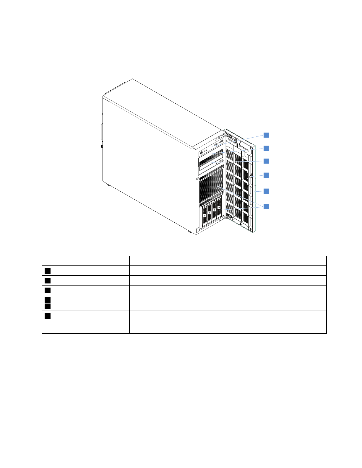
Frontviewoftheserver
1
2
3
4
5
6
0
1
2
3
Thefrontviewoftheservervariesbymodel.Dependingonthemodel,yourservermightlookslightly
differentfromtheillustrationsinthistopic.
Figure2.Servermodelswith3.5-inchdrivebays
ItemDescription
1Frontpanel
2Opticaldrivebay2
3Opticaldrivebay1
4Frontdoorlock
5Frontdoor
63.5-inch-drivebays
See“Frontpanel”onpage14.
Theopticaldrivebay2isforasecondaryopticaldrive.
Theopticaldrivebay1isforanopticaldriveoratapedrive.
YoucanlockthefrontdoortoprotecttheHDDcagesfromunauthorizedaccess.
Thefrontdoorisavailableonsomemodels.
Thenumberoftheinstalleddrivesinyourservervariesbymodel.Thevacant
drivebaysareoccupiedbydummytraysorcoveredbyanEMI-protectivepanel.
Whenyouinstalldrives,followtheorderofthedrivebaynumbers.
Chapter3.Productoverview13
Page 28
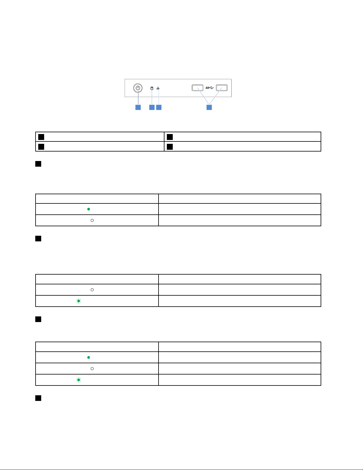
Frontpanel
1 2 3 4
Thefollowingillustrationshowsthecontrol,connectors,andLEDsonthefrontpaneloftheserver.Tolocate
thefrontpanel,see“Frontviewoftheserver”onpage13.
Figure3.Frontpanel
1PowerbuttonwithpowerstatusLED2HDDstatusLED
3NetworkInterfaceController(NIC)statusLED4FrontUSB3.0connectors(2)
1PowerbuttonwithpowerstatusLED
Youcanpressthepowerbuttontoturnonorturnofftheserver.ThepowerstatusLEDhelpsyouto
determinethecurrentpowerstatus.
PowerstatusLEDDescription
Green
Off
Theserverison.
Theserverisoff.
2HDDstatusLED
TheHDDstatusLEDhelpsyoutodeterminethestatusoftheHDDactivity.
Note:TheHDDstatusLEDisavailableonservermodelswithoutadiscreteRAIDcardinstalled.
HDDstatusLEDDescription
Off
Blinkinggreen
3NICstatusLED
TheHDDisnotinuse.
TheHDDisactiveanddataisbeingtransferred.
TheNICstatusLEDindicatestheLANstatusfortheEthernetconnectorontherearpaneloftheserver.
NICstatusLED
Green
Off
Blinkinggreen
4FrontUSB3.0connectors(2)
TheserverisconnectedtoaLAN.
TheserverisdisconnectedfromaLAN.
TheLANisconnectedandactive.
Description
UsedtoattachaUSB-compatibledevice,suchasaUSBkeyboard,mouse,scanner,orprinter.Ifyouhave
morethaneightUSBdevices,youcanpurchaseaUSBhub,whichyoucanusetoconnectadditional
USBdevices.
14ThinkServerTS450UserGuideandHardwareMaintenanceManual
Page 29
Rearviewoftheserver
5 6 7 8
3 4
1
2
3
4
5
6
7
8
9
10
11
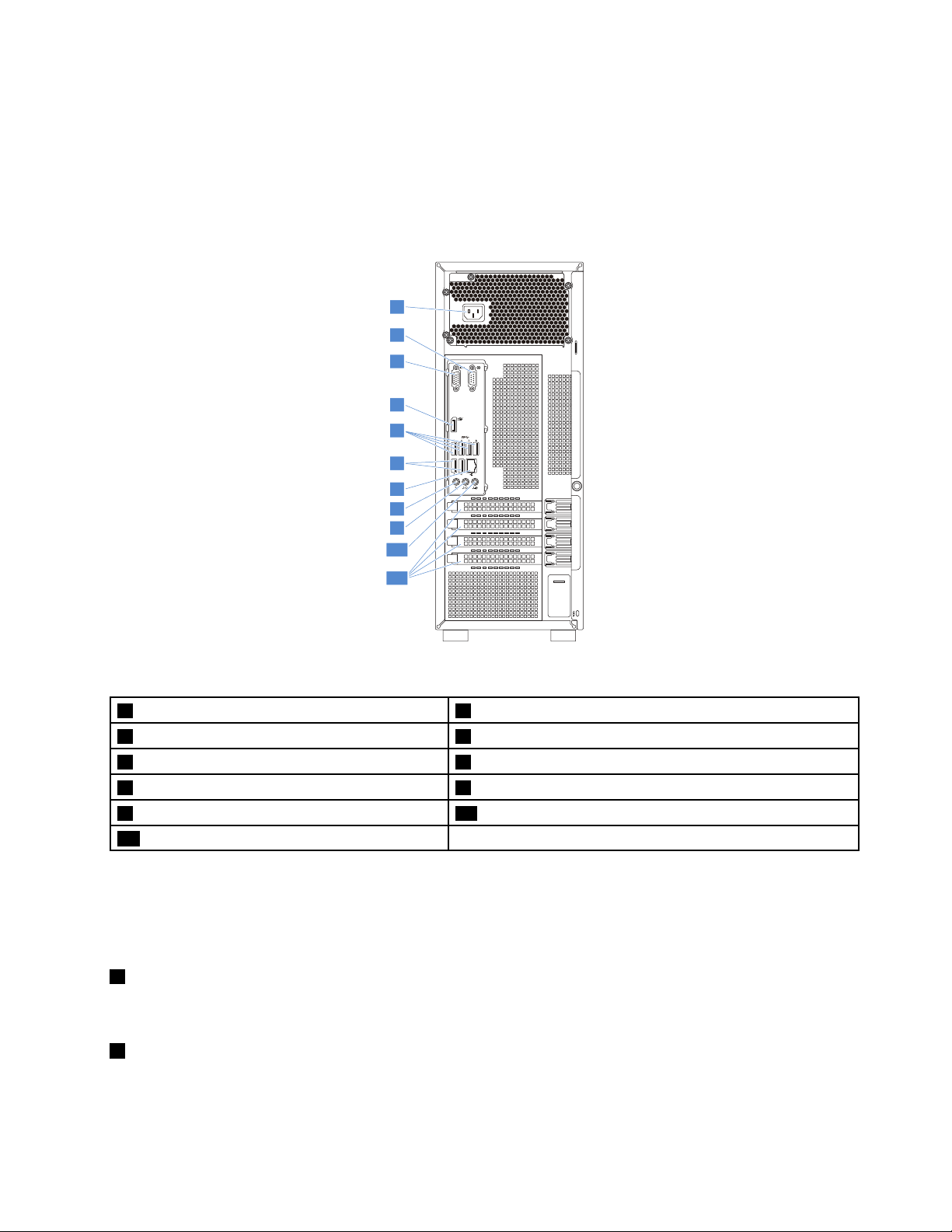
Thistopicprovidesinformationtohelpyoulocatetheconnectorsandcomponentsontherearofyour
server.Thefollowingillustrationshowstherearviewoftheserverwithascrew-secured,non-hot-swap
powersupplyassembly.
Note:Dependingonthemodel,yourservermightlookslightlydifferentfromtheillustrationsinthistopic.
Figure4.Rearviewoftheserver
1Powercordconnector
3VGAconnector(DB-15)
5USB3.0connectors(4)6USB3.0connectors(2)
7Ethernetconnector(RJ-45)
9Audioline-outconnector10Audioline-inconnector
11Expansioncardarea
2Serialconnector
4DisplayPortconnector
8Microphoneconnector
Yourservermodelmighthaveoneortwohot-swapredundantpowersupplies.Eachhot-swapredundant
powersupplyhasonepowercordconnectorontherearoftheserver.Foreachhot-swapredundantpower
supply,theremightbeoneortwostatusLEDsonthepowersupplynearthepowercordconnector.For
informationaboutthestatusLEDs,see“Hot-swappowersupplystatusLEDs”onpage24.
1Powercordconnectors
Usedtoconnectthepowercord.
2Serialconnector
Usedtoattachadevicethatusesa9-pinserialconnector.
Chapter3.Productoverview15
Page 30
3VGAconnector(DB-15)
UsedtoattachaVGA-compatiblevideodevice,suchasaVGAmonitor.
4DisplayPortconnector
Usedtoattachahigh-performancemonitor,adirect-drivemonitor,orotherdevicesthatuseaDisplayPort
connector.
5USB3.0connectors(4)
6USB3.0connectors(2)
UsedtoattachaUSB-compatibledevice,suchasaUSBkeyboard,mouse,scanner,orprinter.Ifyouhave
morethaneightUSBdevices,youcanpurchaseaUSBhub,whichyoucanusetoconnectadditional
USBdevices.
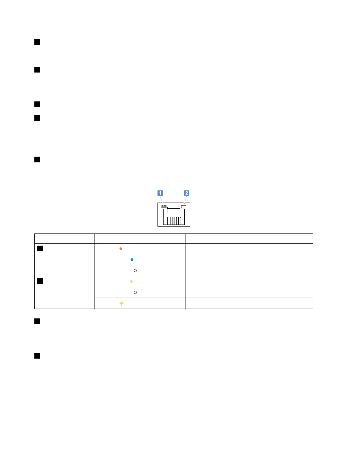
7Ethernetconnector(RJ-45)
UsedtoattachanEthernetcableforaLAN.TheEthernetconnectorhastwostatusLEDstohelpyouidentify
theEthernetconnectivity,activity,andconnectionspeed.
EthernetstatusLED
1Connectionspeed
2Linkandactivity
8Microphoneconnector
Status
Blinkingorange
Blinkingyellow
Theconnectionspeedis1000Mbps.
Green
Off
Yellow
Off
Theconnectionspeedis100Mbps.
Theconnectionspeedis10Mbps.
TheserverisconnectedtoaLAN.
TheserverisdisconnectedfromaLAN.
TheLANisconnectedandactive.
Description
Usedtoattachamicrophonetoyourserverwhenyouwanttorecordsoundorifyouusespeech-recognition
software.
9Audioline-outconnector
Usedtosendaudiosignalsfromthecomputertoexternaldevices,suchaspoweredstereospeakers
(speakerswithbuilt-inamplifiers),headphones,multimediakeyboards,ortheaudioline-inconnectorona
stereosystemorotherexternalrecordingdevice.
16ThinkServerTS450UserGuideandHardwareMaintenanceManual
Page 31

10Audioline-inconnector
Usedtoreceiveaudiosignalsfromanexternalaudiodevice,suchasastereosystem.Whenyouattachan
externalaudiodevice,acableisconnectedbetweentheaudioline-outconnectorofthedeviceandthe
audioline-inconnectorofthecomputer.
11Expansioncardarea
YourserverhasfourexpansionslotsonthesystemboardforyoutoinstallappropriatePeripheral
ComponentInterconnect(PCI)cardsorPCIExpress(PCIe)cards.Fordetailedinformation,see“System
boardcomponents”onpage30.
Note:IfaThinkServerHostBusAdapter(HBA)isavailable,refertoitsuserguidefordetailedinformation.
Theuserguideisavailablefordownloadat:
http://www.lenovo.com/UserManuals
Serverlocks
Lockingtheservercoverpreventsunauthorizedaccesstotheinsideofyourserver.Lockingthefrontdoor
(availableonsomemodels)preventsunauthorizedaccesstotheinstalledHDDs.
Note:Dependingonthemodel,yourservermightlookslightlydifferentfromtheillustrationsinthistopic.
Padlock
Yourservercomeswithapadlockloop.Whenapadlockisinstalled,theservercovercannotberemoved.
Figure5.Padlock
Chapter3.Productoverview17
Page 32

Kensington-stylecablelock
YoucanuseaKensington-stylecablelocktosecureyourservertoadesk,table,orothernon-permanent
fixture.Thecablelockattachestothesecurity-lockslotattherearofyourserverandisoperatedwithakey
orcombinationdependingonthetypeselected.Thecablelockalsolockstheservercover.Thisisthesame
typeoflockusedwithmanynotebookcomputers.YoucanordersuchacablelockdirectlyfromLenovoby
searchingforKensingtonat:
http://www.lenovo.com/support
Figure6.Kensington-stylecablelock
18ThinkServerTS450UserGuideandHardwareMaintenanceManual
Page 33

Frontdoorlock
Youcanremovethekeyattachedontherearoftheserveranduseittoopenorlockthefrontdoorofthe
server.ThefrontdoorprotectstheHDDcagesandpreventsunauthorizedaccesstotheinstalledHDDs.
Figure7.Frontdoorlock
Servercomponents
Thistopicprovidesinformationtohelpyoulocatethecomponentsofyourserver.Formoreinformation
aboutmajorcomponents,seetherelatedtopicsin“Componentlocations”onpage11.
Yourservercomeswithoneofthefollowingdrivebayandbackplaneconfigurations:
DrivebaysizeDrivebay
3.5-inch4
3.5-inch8
2.5-inch8
2.5-inch16
3.5-inch4
2.5-inch/3.5-inch
mixed
quantity
Hot-swap,SATA/SAS
3.5-inchHDDor2.5-inchSSD
Hot-swap,SATA/SAS
3.5-inchHDDor2.5-inchSSD
Hot-swap,SATA/SASHDDorSSDOnebackplane
Hot-swap,SATA/SASHDDorSSD
Non-hot-swapSATAHDDs
4(3.5-inch)
8(2.5-inch)
Hot-swap,SATA/SASHDDorSSD
DrivetypeBackplaneconfiguration
Onebackplane
Twobackplanes:each
supportinguptofourdrives
Twobackplanes:each
supportinguptoeightdrives
Notapplied
Twobackplanes
Chapter3.Productoverview19
Page 34

Note:Dependingonthemodel,yourservermightlookslightlydifferentfromtheillustrationsinthistopic.
1
2
4
8
9
15
16
17
18
3
12
5
6
7
10
11
13
14
19
21
26
25
22
23
24
20
Figure8.Servercomponents
1Tapedrive*
3Frontpanelboardassembly
53.5-inchhot-swap-drivecage*
73.5-inchnon-hot-swapdrive*
92.5-inchhot-swap-drivecage*
11Securedigitalmodule(SDmodule)*
1
1
2
1
2
1
20ThinkServerTS450UserGuideandHardwareMaintenanceManual
2Opticaldrive
1
43.5-inchhot-swapdrive*
63.5-inch-drivebackplane*
82.5-inchhot-swapdrive*
102.5-inch-drivebackplane*
12Frontsystemfans(2)
1
2
1
2
1
Page 35

13ThinkServerRAIDSuperCapacitorModule*
12
15Intrusionswitch*
17Non-hot-swappowersupply*
19Powerdistributionboard*
21Powerdistributionboardcage*
23CPU
25Heatsinkandfanassembly
3
1
1
14PCIecard
16Rearsystemfan
2
3
3
2
18Hot-swappowersupplies(2)*
20Hot-swappowersupplycage*
22Systemboard
24Memorymodule(varybymodel)
26Powerconversionboard*
1
1
1
1
3
1
2
Notes:
•*Availableonsomemodels
1
•
Self-serviceCRUs:Partstobeinstalledorreplacedbycustomerthemselves.
2
•
OptionalCRUs:Partscanbeinstalledorreplacedbycustomersortechniciansundercertainterms
oftheapplicablewarrantyservicetypeforyourcountryorregion.
3
•
Non-CRUs:Partsmustbeinstalledorreplacedonlybytrainedservicetechnicians.
BeforeservicingaLenovoproduct,ensurethatyoureadandunderstand“Readthisfirst:safetyinformation”
onpageiii
.UseonlypartsprovidedbyLenovoforreplacement.ForacompletelistingofFRUinformation,
suchasFRUpartnumbersandsupportedservermodels,goto:
http://www.lenovo.com/serviceparts-lookup
Hot-swapdriveactivityandstatusLEDs
Eachhot-swapdrivehastwoLEDsonthefront.
Figure9.Hot-swapdriveactivityandstatusLEDs
1DriveactivityLED2DrivestatusLEDDescription
OffOff
GreenOff
BlinkinggreenOff
Blinkingamber
Green
(blinkingrapidly,
aboutfourflashes
persecond)
Thedrivehasfailedorisnotpresent.
Thedriveispresentbutnotinuse.
Thedriveisactiveanddataisbeingtransferred.
TheRAIDcontrollerisidentifyingthedrive.
Chapter3.Productoverview21
Page 36

1DriveactivityLED2DrivestatusLEDDescription
1
2
Oneofthefollowingsituations:
•Thedrivehasfailed.Replacethedrive.
•ThestatusofthedriveisUnconfiguredBad.Replacethedrive.
Note:IfadriveinaRAIDarrayisremovedandthenreinstalled
whiletheserverison,thestatusofthedrivewillbeidentifiedas
UnconfiguredBad.Inthiscase,donotreplacethedrive.You
canchangethedrivestatusintoUnconfiguredGoodusingthe
GreenAmber
ThinkServerMegaRAIDSASSoftware.
•ThestatusofthedriveisOffline.Youcanchangethedrive
statusintoOnlineusingtheThinkServerMegaRAIDSAS
Software.
FordetailedinformationaboutusingtheThinkServerMegaRAID
SASSoftware,refertotheThinkServerMegaRAIDSASSoftware
UserGuide.Youcanobtainthemostup-to-datedocumentation
foryourserverfromtheLenovoWebsiteat:
http://www.lenovo.com/UserManuals
Blinkinggreen
Blinkingamber
(blinkingslowly,about
oneflashpersecond)
Thedriveisbeingrebuilt.
Powerconversionboard
Thepowerconversionboardisavailableonservermodelswithanon-hot-swappowersupplyassembly.
Figure10.Powerconversionboard
16-pinpowerconnector28-pinpowerconnector
32-pinpowercontrolconnector
16-pinpowerconnector
Usedtoconnecttheconnectoronthenon-hot-swappowersupplyassembly.
28-pinpowerconnector
Usedtoconnectthepowerconnectoronthebackplane.
32-pinpowercontrolconnector
Usedtoconnecttheconnectoronthefrontpanel.Y oucanusethisconnectortocontrolthebackplane
power.
22ThinkServerTS450UserGuideandHardwareMaintenanceManual
Page 37

Powerdistributionboard
1
2
3
4
5
6
Thepowerdistributionboardisavailableonservermodelswithhot-swappowersupplies.
Figure11.Rearview
Figure12.Frontview
18-pinpowerconnector28-pinpowerconnector
34-pinpowerconnector410-pinpowerconnector
5Slot16Slot2
128-pinpowerconnector
Usedtoconnecttheconnectorsonthebackplane.
34-pinpowerconnector
UsedtoconnecttheCPUpowerconnectoronthesystemboard.
410-pinpowerconnector
Usedtoconnectthepowerconnectoronthesystemboard.
564-pinpowerconnector
Usedtoconnecthot-swappowersupplies.
Chapter3.Productoverview23
Page 38

Hot-swappowersupplystatusLEDs
1
2
3
Eachhot-swappowersupplyhasthreestatusLEDs.
Figure13.Hot-swappowersupplystatusLEDs
1InputstatusLED
Status
Off
Green
2OutputstatusLED
Status
Off
Blinkinggreen
(aboutoneflashevery
twoseconds)
Blinkinggreen
(abouttwoflashes
eachsecond)
Green
3FaultLED
DescriptionAction
Thepowersupplyisdisconnectedfrom
theacpowersource.
Thepowersupplyisconnectedtotheac
powersource.
DescriptionAction
Theserverisofforthepowersupplyisnot
workingproperly.
Thepowersupplyisincoldredundancy
activemode.
Thepowersupplyisincoldredundancy
sleepmode.
Theserverisonandthepowersupplyis
workingproperly.
Noactionisneeded.
Noactionisneeded.
Ifthepowersupplyisnotworkingproperly,
replacethepowersupply.See“Hot-swap
powersupply”onpage78
Noactionisneeded.
Noactionisneeded.
Noactionisneeded.
.
Status
Off
Amber
Thepowersupplyisworkingproperly.Noactionisneeded.
Thepowersupplyhasfailed.
DescriptionAction
Replacethepowersupply.See“Hot-swap
powersupply”onpage78
.
RAIDcard
ThistopichelpsyoulocatetheconnectorsonRAIDcards.Y ourserversupportsthefollowingRAIDcards
(supportedtypevariesbyservermodel):
•LenovoThinkServerRAID520iPCIeAdapter(hereinafterreferredtoasRAID520iAdapter)
•LenovoThinkServerRAID720iPCIeAdapter(hereinafterreferredtoasRAID720iAdapter)
Note:Dependingontheconfiguration,theRAIDcardinstalledinyourservermightlookslightlydifferent
fromtheillustrationsinthistopic.
24ThinkServerTS450UserGuideandHardwareMaintenanceManual
Page 39

LenovoThinkServerRAID520iPCIeAdapter
1 2 3
TheRAID520iAdapterprovidesadvancedSATA/SAShardwareRAIDfunctions.Thefollowingillustration
showstheconnectorsontheadapter.
Figure14.LenovoThinkServerRAID520iPCIeAdapter
Connector
1Connector0Usedtoconnectthemini-SASsignalcableconnectoronthebackplanetosupportHDD0-3.
2Connector1Usedtoconnectthemini-SASsignalcableconnectoronthebackplanetosupportHDD4-7.
3J3connector
Description
UsedtoconnecttoaThinkServerRAID520iupgradekey.
Chapter3.Productoverview25
Page 40

LenovoThinkServerRAID720iPCIeAdapter
1 2 3
TheRAID720iAdapterprovidesadvancedSATA/SAShardwareRAIDfunctions.Thefollowingillustration
showstheconnectorsontheadapter.
Figure15.ThinkServerRAID720iPCIeAdapter
Connector
1Connector0Usedtoconnectthemini-SASsignalcableconnectoronthebackplanetosupportHDD0-3.
2Connector1Usedtoconnectthemini-SASsignalcableconnectoronthebackplanetosupportHDD4-7.
3Thunderbolt
FlashModule
connector
Description
UsedtoconnectaThunderboltMemorymodule(hereinafterreferredtoasTMM).
LenovoThinkServerSAS12GExpanderPCIeCard
ThistopichelpsyoulocatetheconnectorsontheLenovoThinkServerSAS12GExpanderPCIeCard
(hereinafterreferredtoasexpandercard).Theexpandercardisavailableonsomemodels.
Note:TheexpandercardneedstobeinstalledintothePCIeslot3onthesystemboard.
26ThinkServerTS450UserGuideandHardwareMaintenanceManual
Page 41

1 2 3 4 5 6 7
Figure16.LenovoThinkServerSAS12GExpanderPCIeCard
1ConnectorA2ConnectorB
3ConnectorC4ConnectorD
5ConnectorE6ConnectorF
7ConnectorG
ToconnecttheexpandercardwithRAIDcardsorbackplanes,refertothefollowingtable.
ExpandercardRAID520iAdapterRAID720iAdapter
ConnectorAConnector0Connector0
ConnectorBConnector1Connector1
ConnectorsC-GareusedtoconnecttheMini-SASconnectorsonthebackplanes.
Backplane
Yourserversupportsbackplanesforuptofour3.5-inchdrivesanduptoeight2.5-inchdrives.
Tolocatethebackplanes,see“Servercomponents”onpage19.
Backplaneforuptofour3.5-inchdrives
Thistopicprovidesinformationtohelpyoulocatetheconnectorsonthebackplaneforuptofour3.5-inch
drives.
Chapter3.Productoverview27
Page 42

Figure17.Frontview
Figure18.Rearview
1-4Slot0–slot3
Usedtoconnect3.5-inchdrives.
5Mini-SASsignalcableconnector
Usedtoconnectthemini-SASconnectorontheRAIDcard.YoualsocanuseaSATAtomini-SASsignal
cabletoconnectthebackplanetotheSATAconnectorsonthesystemboard.
68-pinpowerconnector
Usedtoconnectthepowerconnectoronthepowerdistributionboard,powerconversionboard,orsystem
board.
Backplaneforuptoeight2.5-inchdrives
Thistopicprovidesinformationtohelpyoulocatetheconnectorsonthebackplaneforuptoeight2.5-inch
drives.
28ThinkServerTS450UserGuideandHardwareMaintenanceManual
Page 43

Figure19.Frontview
Figure20.Rearview
1-8Slot0–slot7
Usedtoconnect2.5-inchdrives.
9Mini-SASsignalcableconnector1
Usedtoconnectthemini-SASconnectorontheRAIDcard.YoualsocanuseaSATAtomini-SASsignal
cabletoconnectthebackplanetotheSATAconnectorsonthesystemboard.
108-pinpowerconnector
Usedtoconnectthepowerconnectoronthepowerdistributionboard,powerconversionboard,orsystem
board.
11Mini-SASsignalcableconnector0
Usedtoconnectthemini-SASconnectorontheRAIDcard.YoualsocanuseaSATAtomini-SASsignal
cabletoconnectthebackplanetotheSATAconnectorsonthesystemboard.
Chapter3.Productoverview29
Page 44

Systemboardcomponents
Thefollowingillustrationshowsthecomponentlocationsonthesystemboard.
Figure21.Systemboardcomponents
14-pinpowerconnector
3CPUfanconnector
5Thermalsensorconnector610-pinpowerconnector
7Frontsystemfan2connector
9HDDpowerconnector1
11SATAconnector512SerialGeneralPurposeInput/Output(SGPIO)
2CPUsocket
4Memoryslots
8HDDpowerconnector2
10SATAconnector4
connector
13SATAconnector214SATAconnector3
15Frontsystemfan1connector
17SATAconnector0
19FrontUSB3.0connector20USB2.0connector
21USB2.0connector22ClearCMOSjumper
23HDDLEDconnector
25PCIeslot326PCIeslot2
27PCIeslot1
29Intrusionswitchconnector
16SATAconnector1
18Frontpanelconnector
24PCIeslot4
28Rearsystemfanconnector
30Coin-cellbattery
30ThinkServerTS450UserGuideandHardwareMaintenanceManual
Page 45

14-pinpowerconnector
Usedtoconnectthe4-pinpowercableofthepowersupply.
2CPUsocket
UsedtoinstalltheCPU.
3CPUfanconnector
UsedtoconnecttheCPUfanontheCPUheatsink.
4Memoryslots
Usedtoinstallmemorymodules.Fordetailedinformation,see“Memorymoduleinstallationrules”on
page56.
5Thermalsensorconnector
Usedtoconnectthethermalsensor.
610-pinpowerconnector
Usedtoconnectthe10-pinpowercableofthepowersupply.
7Frontsystemfan2connector
Usedtoconnectthecableofthefrontsystemfan2.
8HDDpowerconnector2
UsedtoconnectthepowercablesforHDDs,opticaldrive,ortapedrive.
9HDDpowerconnector1
UsedtoconnectthepowercablesforHDDs,opticaldrive,ortapedrive.
101113141617SA T Aconnectors
UsedtoconnecttheHDD,opticaldrive,ortapedrive.
Note:IfyourserverhasoneSATAopticaldriveinstalled,connecttheopticaldrivetoSATAconnector5.If
yourserverhastwoSATAopticaldrivesinstalled,connectthesecondaryopticaldrivetoSATAconnector4.
12SerialGeneralPurposeInput/Output(SGPIO)connector
UsedtoconnecttheSGPIOconnectorofthemini-SASsignalcablewithfourSATAconnectorsandone
SGPIOconnector.
15Frontsystemfan1connector
Usedtoconnectthefrontsystemfan1.
Chapter3.Productoverview31
Page 46

18Frontpanelconnector
Usedtoconnectthefrontpanelboard.
19FrontUSB3.0connector
UsedtoconnectthefrontUSBcable.
2021USB2.0connectors
UsedtoconnectthesignalcablefortheRDXtapedriveortheSDmodule.
22ClearCMOSjumper
UsedtoclearCMOSandturntheBIOSsettingsintothefactorydefaultsettings.
Note:ClearingCMOSdoesnoteraseyourBIOSpasswords.
ToclearCMOS,dothefollowing:
1.Removeallmediafromthedrivesandturnoffallattacheddevicesandtheserver.Then,disconnectall
powercordsfromelectricaloutletsanddisconnectallcablesthatareconnectedtotheserver.
2.Removetheservercover.See“Preparingyourserverinadvanceandremovingtheservercover”
onpage53
.
3.Laytheserveronitssideforeasieroperation.
4.LocatetheClearCMOSjumperonthesystemboard.
5.MovetheClearCMOSjumperfromthedefaultnormalposition(pin1andpin2)totheshort-circuited
position(pin2andpin3).
6.Reconnecttheservertoanacpowersourceandturnontheserver.Then,waitmorethan10seconds.
7.Whenyouhearbeeps,turnofftheserver.Then,movetheClearCMOSjumperbacktothenormal
position(pin1andpin2).
8.Reinstalltheservercoverandconnectthepowercords.See“Completingthepartsreplacement”on
page118.
9.Connecttheservertoanacpowersourceandturnontheserver.TheclearingCMOSprocessis
completed.
23HDDLEDconnector
UsedtoconnectcablefromtheHDDstatusLEDonthefrontpanel.
24252627PCIeslots
Slot
24PCIeslot4
25PCIeslot3
26PCIeslot2
27PCIeslot1
PhysicalslotsizeNegotiablelinkbandwidth
x1x1
x16x4,x1
x1x1
x16x8,x4,x1
32ThinkServerTS450UserGuideandHardwareMaintenanceManual
Supportedcardlength
andheight
Full-length,fullheight
Full-length,fullheight
Full-length,fullheight
Full-length,fullheight
Page 47

28Rearsystemfanconnector
Usedtoconnecttherearsystemfan.
28Intrusionswitchconnector
Usedtoconnecttheintrusionswitch.
30Coin-cellbattery
Yourserverhasaspecialtypeofmemorythatmaintainsthedate,time,andconfigurationinformationfor
built-infeatures.Thecoin-cellbatterykeepstheinformationactivewhenyouturnofftheserver.
Chapter3.Productoverview33
Page 48

34ThinkServerTS450UserGuideandHardwareMaintenanceManual
Page 49

Chapter4.Configuringtheserver
Thischapterprovidesthefollowinginformationtohelpyouconfiguretheserver:
•“UsingtheSetupUtilityprogram”onpage35
•“UsingtheThinkServerEasyStartupprogram”onpage41
•“ConfiguringRAID”onpage44
•“ConfiguringtheEthernetcontrollers”onpage41
UsingtheSetupUtilityprogram
ThistopicprovidesinformationaboutusingtheSetupUtilityprogram.
TheSetupUtilityprogramispartoftheserverfirmware.Y oucanusetheSetupUtilityprogramtoviewand
changetheconfigurationsettingsofyourserver,regardlessofwhichoperatingsystemyouareusing.
However,theoperatingsystemsettingsmightoverrideanysimilarsettingsintheSetupUtilityprogram.
StartingtheSetupUtilityprogram
ThistopicprovidesinstructionsonhowtostarttheSetupUtilityprogram.
TostarttheSetupUtilityprogram,dothefollowing:
1.Connecttheservertoanacpowersourceandpressthepowerbuttononthefrontpaneltoturnonthe
server.See“Turningontheserver”onpage5
2.PresstheF1keyassoonasyouseethelogoscreen.Then,waitforseveralseconds,andtheSetup
Utilityprogramopens.Ifyouhavesetapassword,youneedtotypethecorrectpasswordtoenterthe
SetupUtilityprogram.Forpasswordinformation,see“Usingpasswords”onpage38.
.
SetupUtilityprograminterface
ThistopicprovidesinformationaboutthemenusanditemsintheSetupUtilityprogram.
DependingontheversionofyoursystemBIOS,somemenuoriteminformationmightdifferslightlyfrom
theinformationinthistopic.
Notes:
•Thedefaultsettingsalreadyareoptimizedforyou.Usethedefaultvalueforanyitemyouarenotfamiliar
with.Donotchangethevalueofunfamiliaritemstoavoidunexpectedproblems.Ifyouconsider
changingtheserverconfiguration,proceedwithextremecaution.Settingtheconfigurationinproperly
mightcauseunexpectedresults.IfyoucannotturnontheserverbecauseofincorrectBIOSsettings,
usetheClearCMOSjumpertorestoretheBIOSsettingstothefactorydefaultsettings.See“System
boardcomponents”onpage30
•Ifyouhavechangedanyhardwareintheserver,youmightneedtoreflashtheBIOS.
.
©CopyrightLenovo2015,2016
35
Page 50

ThefollowingmenusarelistedontheBIOSSetupUtilityscreen:
•“Mainmenu”onpage36
.
•“Devicesmenu”onpage36.
•“Advancedmenu”onpage36
.
•“Powermenu”onpage37.
•“Securitymenu”onpage37.
•“Startupmenu”onpage37.
•“Exitmenu”onpage38.
Mainmenu
AfterenteringtheSetupUtilityprogram,youcanseetheMainmenu,whichlistsbasicinformationaboutthe
BIOS,totalmemorysize,andsystemdateandtime.
Devicesmenu
YoucanvieworchangevariousdevicessettingsontheDevicesmenuintheSetupUtilityprogram.Some
itemsaredisplayedonthemenuonlyiftheserversupportsthecorrespondingfeatures.
TheDevicesmenucontainsthefollowingitems.Formoreinformation,enterthecorrespondingsubmenu
andrefertotheinstructionsonthescreen.
MenuitemDescription
SerialPortSetup
USBSetupViewandsetUSBconfigurationparameters.
ATADriveSetupViewandsetSA TAHDDconfigurationparameters.
VideoSetup
AudioSetup
NetworkSetup
Viewandsetserialconnectorconfigurationparameters.
Viewandsettheprimaryvideoadaptertype.
Enableordisabletheonboardaudiocontroller.
EnableordisabletheonboardEthernetcontrollerandothernetwork
functions.
Advancedmenu
YoucanvieworchangevariousservercomponentsettingsontheAdvancedmenuintheSetupUtility
program.TheAdvancedmenucontainsvariousconfigurationitems.Someitemsaredisplayedonthemenu
onlyiftheserversupportsthecorrespondingfeatures.
TheAdvancedmenucontainsthefollowingitems.Formoreinformation,enterthecorrespondingitemsand
refertotheinstructionsonthescreen.
MenuitemDescription
CPUSetupViewandsetCPUconfigurationparameters.
®
Intel
Manageability
IntelSIPPSupportEnableordisabletheIntelSIPPSupportfeature.
CPUCRIDSupportEnableordisabletheCPUCRIDSupportfeature.
ChipsetCRIDsupportEnableordisabletheChipsetCRIDSupportfeature.
36ThinkServerTS450UserGuideandHardwareMaintenanceManual
ViewandsetIntelvPROfeatures.
Page 51

Powermenu
YoucanvieworchangevariousserverpowermanagementsettingsonthePowermenuintheSetupUtility
program.ThePowermenucontainsvariousconfigurationitems.Someitemsaredisplayedonthemenu
onlyiftheserversupportsthecorrespondingfeatures.
ThePowermenucontainsthefollowingitems:
MenuitemDescription
AfterPowerLoss
EnhancedPowerSavingModeEnableordisableEnhancedPowerSavingMode.
IntelligentCoolingEngine(ICE)
AutomaticPowerOnEnableordisabletheAutomaticPowerOnfunction.
Viewandconfigurethesystemperformanceafteracpowersource
isremovedandrestored.
Enablethesystemtoentertheloweracousticlevelorbetterthermal
level.
Securitymenu
YoucansetpasswordsandconfiguretheTPMfunctionontheSecuritymenuintheSetupUtilityprogram.
Someitemsaredisplayedonthemenuonlyiftheserversupportsthecorrespondingfeatures.
TheSecuritymenucontainsthefollowingmainitems:
MenuitemDescription
AdministratorPassword
Power-OnPassword
SetAdministratorPasswordSetanadministratorpasswordtoprotectagainstunauthorizedaccess
SetPower-OnPasswordSetauserpasswordtoprotectagainstunauthorizedaccesstoyour
ChassisIntrusionDetectionEnableordisabletheChassisIntrusionDetectionfeature.
TCGFeatureSetupConfiguretheTPMfunction.See“ConfiguringtheTPMfunction”on
SystemEventLog
SecureBoot
Viewthestatusofanadministratorpassword.
Viewthestatusofauserpassword.
toyourserver.See“Usingpasswords”onpage38
server.See“Usingpasswords”onpage38.
page40.
Viewandclearthesystemeventlog.
Viewandsetsecurebootconfigurationparameters.
.
Startupmenu
TheStartupmenuintheSetupUtilityprogramprovidesaninterfacetohelpyouvieworchangetheserver
startupoptions,includingthestartupsequenceandbootpriorityforvariousdevices.Aftertheserver
restarts,changesinthestartupoptionstakeeffect.
Thestartupsequencespecifiestheorderinwhichtheserverchecksdevicestofindabootrecord.Theserver
startsfromthefirstbootrecordthatitfinds.Forexample,youcandefineastartupsequencethatchecksa
discintheopticaldrive,thencheckstheHDD,andthenchecksanetworkdevice.Forinformationabout
settingthestartupsequenceorselectingastartupdevice,see“Selectingastartupdevice”onpage40.
TheStartupmenucontainsvariousconfigurationsubmenusanditems.Foreachsubmenuanditem,press
Entertoshowselectableoptionsandselectadesiredoptionbyusingtheupanddownarrowkeysortype
desiredvaluesfromthekeyboard.Someitemsaredisplayedonthemenuonlyiftheserversupportsthe
correspondingfeatures.
Chapter4.Configuringtheserver37
Page 52

TheStartupmenucontainsthefollowingsubmenus:
MenuitemDescription
PrimaryBootSequence
AutomaticBootSequence
ErrorBootSequence
Thissequenceisusedwhenthesystemispoweredupproperly.
Thissequenceisusedwhenacommunicationdevicewakesupthe
system.
Thissequenceisusedwhenanerroroccurs.
TheStartupmenucontainsthefollowingitems:
•CSM:IfyouselectEnabled,youcaninstallanon-UEFIoperatingsystem.IfyouselectDisabled,you
caninstallaUEFIoperatingsystem.
•BootMode:Choosethebootpolicy.
•BootPriority:Setthebootpriorityofoperatingsystems.
•OptionsKeysDisplay:IfyouselectEnabled,theoptionkeyswillbedisplayedonthelogoscreen.Ifyou
selectDisabled,theoptionkeyswillnotbedisplayedonthelogoscreen.
•OptionsKeysDisplayStyle:ThisitemcontrolstheoptionkeysdisplaystylewhenyouselectEnabled
fortheOptionKeysDisplayitem.
–IfyouselectLegacy,themessage“PressF1toenterSetup,F12todisplayBootMenu”willbe
displayedonthelogoscreen.
–IfyouselectNormal,themessage“Tointerruptnormalstartup,pressEnter”willbedisplayedon
thelogoscreen.
Exitmenu
AfteryoufinishviewingorchangingsettingsintheSetupUtilityprogram,youcanchooseadesiredaction
fromtheExitmenutosavechanges,discardchanges,orloaddefaultvalues,andexittheprogram.Press
EntertoselecttheitemontheExitmenu,andthenselectYeswhenpromptedtoconfirmtheaction.For
informationaboutexitingtheSetupUtilityprogram,see“ExitingtheSetupUtilityprogram”onpage40
.
TheExitmenucontainsthefollowingitems:
MenuitemDescription
SaveChangesandExitSavechangesandexittheSetupUtilityprogram.
DiscardChangesandExitDiscardchanges,loadpreviousvalues,andthenexittheSetupUtility
program.
LoadOptimalDefaults
OSOptimizedDefaultsSelectEnabledtomeettheMicrosoftWindows8certification
Restoretheuserdefaultvaluesforalltheitems.
requirement.ThesettingsfortheCSMsupport,bootmode,boot
priority,secureboot,andsecurityRollBackpreventionwillbeaffected.
Usingpasswords
ByusingtheSetupUtilityprogram,youcansetapasswordtopreventunauthorizedaccesstoyourserver.
Youdonothavetosetapasswordtouseyourserver.However,usingapasswordimprovescomputing
security.Ifyoudecidetosetapassword,readthefollowingtopics.
SetupUtilityprogrampasswordtypes
ThefollowingtypesofpasswordsareavailableintheSetupUtilityprogram:
38ThinkServerTS450UserGuideandHardwareMaintenanceManual
Page 53

•Administratorpassword
Settinganadministratorpassworddetersunauthorizedusersfromchangingconfigurationsettings.Ifyou
areresponsibleformaintainingtheconfigurationsettingsofseveralcomputers,youmightwanttoset
anadministratorpassword.Whenanadministratorpasswordisset,youarepromptedtotypeavalid
passwordeachtimeyoutrytoaccesstheSetupUtilityprogram.TheSetupUtilityprogramcannot
beaccesseduntilavalidpasswordistypedin.
•Power-Onpassword
Whenapower-onpasswordisset,theservercannotbeuseduntilavalidpasswordistypedin.
Note:Ifboththeadministratorpasswordandpower-onpasswordareset,youcantypeeitherpasswordto
usetheserver.However,youmustuseyouradministratorpasswordtochangeanyconfigurationsettings.
Passwordconsiderations
Forsecurityreasons,itisrecommendedthatyouuseastrongpasswordthatcannotbeeasilycompromised.
Notes:
1.TheSetupUtilityprogrampasswordsarenotcasesensitive.
2.TheserversupportsSetupUtilityprogrampasswordsthatconsistofupto20characters.
Tosetastrongpassword,usethefollowingguidelines:
•Haveatleasteightcharactersinlength
•Containatleastonealphabeticcharacterandonenumericcharacter
•Notbeyournameoryourusername
•Notbeacommonwordoracommonname
•Besignificantlydifferentfromyourpreviouspasswords
Besidesthealphabeticcharacters(a-z)andnumericcharacters(0-9),theserveralsosupportscharacters
typedusingspecialkeysonthekeyboardforapassword.Refertothehelpmessageonthescreenwhen
settingapasswordtodeterminethevalidspecialcharacters.
Setting,changing,ordeletingapassword
Thistopicprovidesinstructionsonhowtoset,change,ordeleteapasswordintheSetupUtilityprogram.
Toset,change,ordeleteapasswordintheSetupUtilityprogram,dothefollowing:
1.StarttheSetupUtilityprogram.See“StartingtheSetupUtilityprogram”onpage35.
2.OntheSecuritymenu,selectSetAdministratorPasswordtosetanadministratorpasswordorselect
SetPower-OnPasswordtosetauserpassword.
3.See“Passwordconsiderations”onpage39.Then,followtheinstructionsonthescreentosetor
changeapassword.
4.Ifyouwanttodeleteapassword,typeyourcurrentpassword.PressEnterwhenyouareprompted
totypeanewpassword.Then,pressEntertoconfirmthenewpassword.Thepreviouspassword
willbecleared.
Note:Forsecurityreasons,itisrecommendedthatyoualwayssetapasswordforyourserver.
5.PressF10tosavesettingsandexittheSetupUtilityprogram.
Ifyouhaveforgottenthepassword,youcanusetheClearCMOSjumperonthesystemboardtoerasethe
password.See“Systemboardcomponents”onpage30
.Then,setanewpasswordfortheserver.
Chapter4.Configuringtheserver39
Page 54

ConfiguringtheTPMfunction
TheTPMchipisintegratedonthesystemboardandworksasahardwaresecuritysolutiontohelpyou
toencryptdataandprotecttheserver.
ToenabletheTPMfunctionintheSetupUtilityprogram,dothefollowing:
1.StarttheSetupUtilityprogram.See“StartingtheSetupUtilityprogram”onpage35.
2.OntheSecuritymenu,selectTCGFeatureSetup,andthenpressEnter.
3.SelectTCGSecurityFeatures.Then,settheTPMSupporttoActive.
4.PressF10tosavesettingsandexittheSetupUtilityprogram.Theserverwillrestartinordertoenable
theTPMfunction.
Selectingastartupdevice
IfyourserverdoesnotstartupfromadesireddevicesuchasthediscorHDDasexpected,dooneofthe
followingtoselectthestartupdeviceyouwant:
Note:Notalldiscs,HDDs,orotherremovabledevicesarebootable.
•Toselectatemporarystartupdevice,dothefollowing:
Note:Selectingastartupdeviceusingthefollowingmethoddoesnotpermanentlychangethestartup
sequence.
1.Turnonorrestartyourserver.
2.Whenyouseethelogoscreen,pressF12todisplaythebootmenu.Thebootdeviceselection
windowopens.
3.Inthebootdeviceselectionwindow,usetheupanddownarrowkeysonthekeyboardtoswitch
betweentheselections.PressEntertoselectthedeviceofyourchoice.Then,theserverwillstart
upfromtheselecteddevice.
•Tovieworpermanentlychangetheconfiguredstartupdevicesequence,dothefollowing:
1.StarttheSetupUtilityprogram.See“StartingtheSetupUtilityprogram”onpage35.
2.OntheStartupmenu,followtheinstructionsonthescreentosetthestartupdevicedependingon
yourneeds.Youalsocansetthebootpriorityforvariousdevices.See“Startupmenu”onpage37.
3.PressF10tosavesettingsandexittheSetupUtilityprogram.Theserverwillfollowthestartupdevice
sequenceyouhaveseteachtimeyouturnontheserver.
ExitingtheSetupUtilityprogram
Afteryoufinishviewingorchangingsettings,pressEsctoreturntotheSetupUtilityprogrammaininterface.
Ifyouareonanestedsubmenu,pressEscrepeatedlyuntilyoureachthemaininterface.T oexittheSetup
Utilityprogram,youalsocandothefollowing:
•PressF10tosavethenewsettingsandexittheSetupUtilityprogram.
•pressF9toreturntothedefaultsettings.
FormoreinformationabouttheExitmenuintheSetupUtilityprogram,see“Exitmenu”onpage38
.
UpdatingtheBIOS
ThistopicprovidesinstructionsonhowtoupdatetheBIOS.
Systemprogramsarethebasiclayerofsoftwarebuiltintoyourserver.SystemprogramsincludethePOST,
theUEFIBIOS,andtheSetupUtilityprogram.ThePOSTisasetoftestsandproceduresthatareperformed
40ThinkServerTS450UserGuideandHardwareMaintenanceManual
Page 55

eachtimeyouturnonyourserver.TheUEFIBIOSisalayerofsoftwarethattranslatesinstructionsfrom
otherlayersofsoftwareintoelectricalsignalsthattheserverhardwarecanexecute.Youcanusethe
SetupUtilityprogramtovieworchangetheconfigurationsettingsofyourserver.See“UsingtheSetup
Utilityprogram”onpage35
LenovomightmakechangesandenhancementstotheBIOS.Whenupdatesarereleased,theyareavailable
fordownloadontheLenovoWebsiteathttp://www.lenovo.com/drivers.Y oucanupdatetheserverfirmware
bydownloadinganupdatepackageandfollowingtheinstructionsontheWebpage.
YoualsocanusetheFirmwareUpdaterprogramtohelpyoukeeptheserverfirmwareup-to-date.See
“Serversetupprocedure”onpage5.
.
Updating(flashing)theBIOS
Thistopicprovidesinstructionsonhowtoupdate(flash)theBIOS.
Notes:
•UpdatetheBIOSonyourserveronlyifthenewerBIOSversionspecificallysolvesaproblemyouhave.
WedonotrecommendBIOSupdatesforserversthatdonotneedthem.Y oucanviewtheupdated
informationforthenewBIOSversionintheinstallationinstructionsfortheBIOSupdateutilityprogram.
•DowngradingtheBIOStoanearlierversionisnotrecommendedandmightnotbesupported.Anearlier
BIOSversionmightnotcontainthesupportforthelatestsystemconfigurations.
•IfthepowertoyourserverisinterruptedwhilethePOSTandBIOSarebeingupdated,yourservermight
notrestartproperly.EnsurethatyouperformtheBIOSupdateprocedureinanenvironmentwitha
steadypowersupply.Besides,ensurethatyourservercanrestartsuccessfullywithoutencountering
hardwareproblems.
•IfyouhaveupdatedtheBIOSfirmware,alltheBIOSsettingsbecomethedefaultsettingsoftheupdated
BIOSversion.Y ouneedtocheckandreconfiguretheBIOSsettingsforyourspecificneeds.
Toupdate(flash)theBIOS,dothefollowing:
1.Gotohttp://www.lenovo.com/driversandfollowtheinstructionsontheWebpagetolocatetheBIOS
updatepackage.
2.DownloadtheBIOSupdatepackageandtheTXTfilethatcontainsinstallationinstructions.
3.PrinttheTXTfileandfollowtheinstructionstoupdate(flash)theBIOS.
4.CheckandreconfiguretheBIOSsettingsforyourspecificneedsbasedonyournoteorreferto“Using
theSetupUtilityprogram”onpage35aftertheBIOSupdateprocessiscompleted.
ConfiguringtheEthernetcontrollers
TheEthernetcontrollersareintegratedonthesystemboard.Theyprovideaninterfaceforconnectingto
a10Mbps,100Mbps,or1000Mbpsnetworkandprovidefull-duplex(FDX)capability,whichenables
simultaneoustransmissionandreceptionofdataonthenetwork.
YoudonothavetosetanyjumpersorconfiguretheEthernetcontrollers.However,youmustinstalladevice
drivertoenabletheoperatingsystemtorecognizethecontrollers.
ThedevicedriversforonboardEthernetcontrollersareavailablefordownloadat:
http://www.lenovo.com/drivers
UsingtheThinkServerEasyStartupprogram
TheThinkServerEasyStartupprogramsimplifiestheprocessofconfiguringRAIDandinstallingsupported
WindowsandLinuxoperatingsystemsanddevicedriversonyourserver.Theprogramworkswithyour
Chapter4.Configuringtheserver41
Page 56

WindowsorLinuxoperatingsysteminstallationdisctoautomatetheprocessofinstallingtheoperating
systemandassociateddevicedrivers.Thisprogramisprovidedwithyourserveronaself-starting(bootable)
ThinkServerEasyStartupDVD.TheuserguidefortheprogramisalsoontheDVDandcanbeaccessed
directlyfromtheprograminterface.
IfyoudonothaveaThinkServerEasyStartupDVD,youalsocandownloadanISOimagefromtheLenovo
SupportWebsiteandmakeadiscbyyourself.
TodownloadtheThinkServerEasyStartupprogramimageandburnitintoadisc,dothefollowing:
1.Gotohttp://www.lenovo.com/driversandfollowtheinstructionsontheWebpagetolocatethe
ThinkServerEasyStartupprogram.
2.DownloadtheISOimagefortheThinkServerEasyStartupprogramandthereadmefile.Thereadmefile
containsimportantinformationabouttheThinkServerEasyStartupprogram.
3.Printthereadmefileandreaditcarefully.
4.UseanopticaldriveandanyDVDburningsoftwaretocreateabootablediscwiththeISOimage.
FeaturesoftheThinkServerEasyStartupprogram
TheThinkServerEasyStartupprogramhasthefollowingfeatures:
•Containedinaself-starting(bootable)DVD
•Easy-to-use,language-selectableinterface
•Integratedhelpsystemanduserguide
•Automatichardwaredetection
•RAIDconfigurationutility
•Devicedriversprovidedbasedontheservermodelanddetecteddevices
•Selectablepartitionsizeandfilesystemtype
•Supportformultipleoperatingsystems
•Abilitytoinstalltheoperatingsystemanddevicedriversinanunattendedmodetosavetime
•AbilitytocreateareusableresponsefilethatcanbeusedwithsimilarlyconfiguredLenovoserversto
makefutureinstallationsevenfaster
StartingtheThinkServerEasyStartupprogram
ThistopicprovidesinstructionsonhowtostarttheThinkServerEasyStartupprogram.Afteryoustartthe
programandenterthemaininterface,clickUserGuidefordetailedinformationaboutusingthisprogramto
helpyouconfiguretheserverandinstallanoperatingsystem.
TostarttheThinkServerEasyStartupprogram,dothefollowing:
1.InserttheThinkServerEasyStartupDVDintotheopticaldrive,settheopticaldriveasthefirststartup
device,andstartyourserverfromtheDVDintheopticaldrive.See“Selectingastartupdevice”on
page40
2.WaitfortheThinkServerEasyStartupprogramtoload.Then,youarepromptedforthefollowing
selections:
•Thelanguageinwhichyouwanttoviewtheprogram
•Thelanguageofthekeyboardlayoutyouwillbeusingwiththeprogram
Note:ThesupportedlanguagesandkeyboardlayoutsfortheThinkServerEasyStartupprogramare
German,English,Spanish,French,Italian,Dutch,Turkish,andJapanese.YourThinkServerEasyStartup
DVDmightbeEnglishonly.Inthiscase,thekeyboardlayoutshouldbeEnglish.
42ThinkServerTS450UserGuideandHardwareMaintenanceManual
.
Page 57

3.Afterselectingthelanguageandkeyboardlayout,clickOK.Then,youwillseeoneormoremessages
aboutconfiguringstoragedevices.ClickNextwhenyouarepromptedwiththeLenovoLicense
Agreement.ReadtheLenovoLicenseAgreementcarefully.Inordertocontinue,youmustagreethose
termsbyclickingAgree.Then,theDateandtimewindowopens.
4.SetthecurrentdateandtimeandclickOK.TheStartoptionwindowopens.
5.TheStartoptionwindowprovidesthefollowingselections:
•Continuetothemaininterface.
•Installtheoperatingsystemusingapre-existingresponsefile.
•ConfigureRAIDusingapre-existingresponsefile.
Readtheexplanationsonthescreenandselectadesiredoption.Then,followtheinstructionsonthe
screen.IfthisisthefirsttimeyouareusingtheThinkServerEasyStartupprogram,selecttheoptionto
continuetothemaininterfaceandviewthecompatibilitynotesanduserguide.
Notes:
1.FunctionalityandsupportedoperatingsystemsvarydependingontheversionoftheThinkServer
EasyStartupprogram.Fromthemaininterfaceoftheprogram,clickCompatibilitynotestoviewthe
informationabouttheRAIDcontrollers,operatingsystems,andserverconfigurationssupportedbythe
specificversionoftheprogram.ClickUserGuidetoviewthevariousfunctionsandlearnhowto
usetheprogram.
2.BeforeusingtheThinkServerEasyStartupprogramtoinstallanoperatingsystem,ensurethatany
externalstoragedevicesandfiberchannelsareconfiguredproperly.
TheThinkServerEasyStartupprogrammaininterfaceprovidesthefollowingmenusontheleftpaneof
thescreen:
•Home
Thismenuisthewelcomepagethatcontainssomegeneraldescriptionsabouttheprogramandthe
Lenovocopyrightandtrademarkstatements.
•Compatibilitynotes
ThismenuprovidesinformationabouttheRAIDcontrollers,operatingsystems,andserverconfigurations
supportedbytheversionoftheprogramyouareusing.
•UserGuide
Thismenuprovidesinformationaboutthefeaturesoftheprogramandinstructionsonhowtousethe
program.
•Hardwarelist
Thismenudisplaysalistofhardwaredevicesdetectedbytheprogram.
•ConfigureRAID
ThismenuprovidesinstructionsonhowtoconfigureRAIDorviewthecurrentRAIDconfigurationand
makechangesifneeded.
•Installoperatingsystem
Thismenudisplaysaseriesofchoicesandpromptstocollectinformationrequiredforoperatingsystem
installation,preparestheharddiskdriveforinstallation,andtheninitiatestheinstallationprocessusing
youroperatingsysteminstallationdisc.
•About
Thismenuprovidestheversioninformationandlegalnotices.
Chapter4.Configuringtheserver43
Page 58

ConfiguringRAID
ThistopicprovidesinformationaboutRAIDandtheutilityprogramsthatareavailableforyoutoconfigure
RAID.
Thistopiccontainsthefollowingitems:
•“AboutRAID”onpage44
•“RAIDforyourserver”onpage45
•“ConfiguringonboardSATAsoftwareRAID”onpage46
•“ConfiguringadvancedSATAorSAShardwareRAID”onpage48
AboutRAID
RAID,anacronymforRedundantArrayofIndependentDisks,isatechnologythatprovidesincreased
storagefunctionsandreliabilitythroughredundancy.ThisisachievedbycombiningmultipleHDDsintoa
logicalunit,wheredataisdistributedacrossthedrivesinoneofseveralwayscalledRAIDlevels.
WhenagroupofindependentphysicalHDDsaresetuptouseRAIDtechnology,theyareinaRAIDarray.
ThisarraydistributesdataacrossmultipleHDDs,butthearrayappearstothehostserverasonesingle
storageunit.CreatingandusingRAIDarraysprovideshighperformance,suchastheexpeditedI/O
performance,becauseseveraldrivescanbeaccessedsimultaneously.
RAIDdrivegroupsalsoimprovedatastoragereliabilityandfaulttolerancecomparedwithsingle-drive
storagesystems.Datalossresultingfromadrivefailurecanbepreventedbyreconstructingmissingdata
fromtheremainingdrives.
ThefollowinglistdescribessomeofthemostcommonlyusedRAIDlevels:
•RAID0:block-levelstripingwithoutparityormirroring
SimplestripesetsarenormallyreferredtoasRAID0.RAID0usesstripingtoprovidehighdata
throughput,especiallyforlargefilesinanenvironmentthatdoesnotrequirefaulttolerance.RAID0hasno
redundancyanditprovidesimprovedperformanceandadditionalstoragewithoutfaulttolerance.Any
drivefailuredestroysthearrayandthelikelihoodoffailureincreaseswithmoredrivesinthearray.RAID
0doesnotimplementerrorchecking,soanyerrorisuncorrectable.Moredrivesinthearraymeans
higherbandwidth,butgreaterriskofdataloss.
RAID0requiresaminimumnumberofoneharddiskdrive.
•RAID1:mirroringwithoutparityorstriping
RAID1usesmirroringsothatdatawrittentoonedriveissimultaneouslywrittentoanotherdrive.Thisis
goodforsmalldatabasesorotherapplicationsthatrequiresmallcapacitybutcompletedataredundancy.
RAID1providesfaulttolerancefromdiskerrorsorfailuresandcontinuestooperateaslongasatleast
onedriveinthemirroredsetisfunctioning.Withappropriateoperatingsystemsupport,therecanbe
increasedreadperformanceandonlyaminimalwriteperformancereduction.
RAID1requiresaminimumnumberoftwoHDDs.
44ThinkServerTS450UserGuideandHardwareMaintenanceManual
Page 59

•RAID5:block-levelstripingwithdistributedparity
RAID5usesdiskstripingandparitydataacrossalldrives(distributedparity)toprovidehighdata
throughput,especiallyforsmallrandomaccess.RAID5distributesparityalongwiththedataandrequires
alldrivesbutonetobepresenttooperate;drivefailurerequiresreplacement,butthearrayisnot
destroyedbyasingledrivefailure.Upondrivefailure,anysubsequentreadoperationscanbecalculated
fromthedistributedparitysothatthedrivefailureismaskedfromtheenduser.Thearraywillhavedata
lossintheeventofaseconddrivefailureandisvulnerableuntilthedatathatwasonthefailingdriveis
rebuiltontoareplacementdrive.Asingledrivefailureinthesetwillresultinreducedperformanceof
theentiresetuntilthefailingdrivehasbeenreplacedandrebuilt.
RAID5requiresaminimumnumberofthreeHDDs.
•RAID6:block-levelstripingwithdistributedparity
RAID6usesdistributedparity,withtwoindependentparityblocksperstripe,anddiskstriping.ARAID6
virtualdrivecansurvivethelossofanytwodriveswithoutlosingdata.ARAID6drivegroupissimilar
toaRAID5drivegroup.Blocksofdataandparityinformationarewrittenacrossalldrives.Theparity
informationisusedtorecoverthedataifoneortwodrivesfailinthedrivegroup.
RAID6requiresaminimumnumberofthreeHDDs.
•RAID10:acombinationofRAID0andRAID1
RAID10consistsofstripeddataacrossmirroredspans.ARAID10drivegroupisaspanneddrive
groupthatcreatesastripedsetfromaseriesofmirroreddrives.RAID10allowsamaximumofeight
spans.YoumustuseanevennumberofdrivesineachRAIDvirtualdriveinthespan.TheRAID1
virtualdrivesmusthavethesamestripesize.RAID10provideshighdatathroughputandcompletedata
redundancybutusesalargernumberofspans.
RAID10requiresaminimumnumberoffourHDDsandalsorequiresanevennumberofdrives,for
example,sixHDDsoreightHDDs.
•RAID50:acombinationofRAID0andRAID5
RAID50usesdistributedparityanddiskstriping.ARAID50drivegroupisaspanneddrivegroupin
whichdataisstripedacrossmultipleRAID5drivegroups.RAID50worksbestwithdatathatrequires
highreliability,highrequestrates,highdatatransfers,andmedium-to-largecapacity.
Note:HavingvirtualdrivesofdifferentRAIDlevels,suchasRAID0andRAID5,inthesamedrivegroupis
notallowed.Forexample,ifanexistingRAID5virtualdriveiscreatedoutofpartialspaceinanarray,the
nextvirtualdriveinthearrayhastobeRAID5only.
RAID50requiresaminimumnumberofsixHDDs.
•RAID60:acombinationofRAID0andRAID6
RAID60usesdistributedparity,withtwoindependentparityblocksperstripeineachRAIDset,anddisk
striping.ARAID60virtualdrivecansurvivethelossoftwodrivesineachoftheRAID6setswithout
losingdata.RAID60worksbestwithdatathatrequireshighreliability,highrequestrates,highdata
transfers,andmedium-to-largecapacity.
RAID60requiresaminimumnumberofsixHDDs.
FordetailedinformationaboutRAID,referto“IntroductiontoRAID”intheMegaRAIDSASSoftwareUser
Guide.ThisguideisavailableontheLenovoSupportWebsiteat:
http://www.lenovo.com/support
RAIDforyourserver
Note:BeforeconfiguringRAIDforyourserver,ensurethatyouuseHDDsthatareofthesametype(SATAor
SAS)andhavethesamecapacitywithinasingleRAIDarray.
YourserversupportsthefollowingtwotypesofRAIDconfigurations:
Chapter4.Configuringtheserver45
Page 60

•OnboardSA T AsoftwareRAIDconfiguration
TheonboardSATAsoftwareRAIDcontrollerisintegratedontheIntelC220chiponthesystemboard.
IfyourserverhasSATAHDDsthatareconnectedtothesystemboard,youcanusetheIntelRapid
StorageTechnologyenterpriseprogramtoconfigureRAID.Bydefault,yourserversupportsonboardSATA
softwareRAIDlevels0,1,5,and10.
Fordetailedinformation,see“ConfiguringonboardSATAsoftwareRAID”onpage46
•AdvancedSA T A/SAShardwareRAIDconfiguration(requiresaRAIDcard)
SomeservermodelscomewitharequiredRAIDcardtoprovideadvancedSATA/SAShardwareRAID
functionstotheserver.Y oualsocanpurchasetheRAIDcardfromLenovoandinstallitintoservermodels
thatsupporttheRAIDcardtogetadvancedSATA/SAShardwareRAIDfunctions.See“RAIDcard”on
page24and“PCIecard”onpage58formoreinformation.
TheRAIDcardprovidestheWebBIOSConfigurationUtilityprogramtohelpyouconfigureRAID
independentlyoftheoperatingsystem.YoualsocaninstalltheMegaRAIDStorageManagerprogram
andtheStorCLIConfigurationUtilityprogramtohelpyoumanagetheRAIDarrayandRAIDcontroller
inanoperatingsystemenvironment.ThesupportedRAIDlevelsareRAID0,1,and10bydefault.For
theThinkServerRAID520iPCIeAdapter,toactivateRAID5andRAID50levels,installaRAID5keyon
theRAIDcard.FortheThinkServerRAID720iPCIeAdapter,toactivateRAID6andRAID60levels,you
needtoinstallaTMMontheRAIDcard.
Fordetailedinformation,see“ConfiguringadvancedSATAorSAShardwareRAID”onpage48
Notes:
•ForservermodelswithmorethanfourHDDsormodelsthatuseSASHDDs,aRAIDcardmustbeinstalled.
•WhentheCPUutilizationishigh,itisrecommendedthatyouinstallaRAIDcardinsteadofusingthe
integratedsoftwareRAIDcontrollerforRAID5configuration.
•TheThinkServerEasyStartupprogramsimplifiestheprocessofconfiguringsupportedRAIDandinstalling
supportedoperatingsystemsanddevicedrivers.
.
.
BeforeconfiguringRAIDforyourserver,observethefollowingprecautions:
1.UseHDDsthathavethesamecapacitywithinasingleRAIDarray.
2.UseHDDsthatareofthesametype(SATAorSAS)withinasingleRAIDarray.
3.Dependingontheoperatingsystem,theprimaryRAIDmightbelimitedto2TBtotaldrivecapacity.
ConfiguringonboardSATAsoftwareRAID
•“EnablingtheonboardSATARAIDfunctionality”onpage46
•“CreatingRAIDvolumes”onpage47
•“DeletingRAIDvolumes”onpage47
•“Resettingdiskstonon-RAID”onpage47
•“Markingdisksasspare”onpage48
EnablingtheonboardSA TARAIDfunctionality
Note:Usethearrowkeysonthekeyboardtomakeselections.
ToenableonboardSATARAIDfunctionality,dothefollowing:
1.StarttheSetupUtilityprogram.See“StartingtheSetupUtilityprogram”onpage35.
2.SelectDevices➙ATADriveSetup.
3.SelectConfigureSATAasandpressEnter.
4.SelectRAIDandpressEnter.
46ThinkServerTS450UserGuideandHardwareMaintenanceManual
Page 61

5.PressF10tosavechangesandexittheSetupUtilityprogram.
CreatingRAIDvolumes
ThissectiondescribeshowtousetheIntelRapidStorageTechnologyenterpriseoptionROMconfiguration
utilitytocreateRAIDvolumes.
TocreateRAIDvolumes,dothefollowing:
1.PressCtrl+IwhenpromptedtoentertheIntelRapidStorageTechnologyenterpriseoptionROM
configurationutilityduringsystemstartup.
2.UsetheupanddownarrowkeystoselectCreateRAIDVolumeandpressEnter.
3.TypeaproperRAIDvolumenameintheNamefieldandpressTab.
4.UsethearrowkeystoselectaRAIDlevelintheRAIDLevelfieldandpressT ab.
5.Ifappropriate,usethearrowkeystoselectastripesizeintheStripeSizefieldandpressTab.
6.TypeavolumesizeintheCapacityfieldandpressTab.
7.PressEntertoinitiatevolumecreation.
8.Whenprompted,pressYtoacceptthewarningmessageandcreatethevolume.
9.Ifdesired,returntostep2tocreateadditionalRAIDvolumes.
10.Whenfinished,selectExitandpressEnter.
DeletingRAIDvolumes
ThissectiondescribeshowtousetheIntelRapidStorageTechnologyenterpriseoptionROMconfiguration
utilitytodeleteRAIDvolumes.
TodeleteRAIDvolumes,dothefollowing:
1.PressCtrl+IwhenpromptedtoentertheIntelRapidStorageTechnologyenterpriseoptionROM
configurationutilityduringsystemstartup.
2.UsetheupanddownarrowkeystoselectDeleteRAIDVolumeandpressEnter.
3.UsethearrowkeystoselecttheRAIDvolumetobedeletedandpressDelete.
4.Whenprompted,pressYtoconfirmthedeletionoftheselectedRAIDvolume.DeletingaRAIDvolume
willresettheharddiskdrivestonon-RAID.
5.AfterdeletingaRAIDvolume,youcan:
•Returntostep2todeleteadditionalRAIDvolumes.
•See“CreatingRAIDvolumes”onpage47
•UsetheupanddownarrowkeystoselectExitandpressEnter.
forRAIDvolumecreation.
Resettingdiskstonon-RAID
ThissectiondescribeshowtoresetyourHDDstonon-RAID.
ToresetyourHDDstonon-RAID,dothefollowing:
1.PressCtrl+IwhenpromptedtoentertheIntelRapidStorageTechnologyenterpriseoptionROM
configurationutilityduringsystemstartup.
2.UsetheupanddownarrowkeystoselectResetDiskstoNon-RAIDandpressEnter.
3.Usethearrowkeysandthespacekeytomarkindividualphysicalharddiskdrivestobereset,andthen
pressEntertocompletetheselection.
4.Whenprompted,pressYtoconfirmtheresetaction.
5.AfterresettingtheHDDstonon-RAID,youcan:
•See“DeletingRAIDvolumes”onpage47forRAIDvolumedeletion.
Chapter4.Configuringtheserver47
Page 62

•See“CreatingRAIDvolumes”onpage47forRAIDvolumecreation.
•UsetheupanddownarrowkeystoselectExitandpressEnter.
Markingdisksasspare
Tomarkharddiskdrivesassparedrives,dothefollowing:
1.Duringthesystemstartup,pressCtrl+IwhenpromptedtoentertheIntelRapidStorageTechnology
enterpriseoptionROMconfigurationutility.
2.UsetheupanddownarrowkeystoselectMarkDisksasSpareandpressEnter.
3.Usethearrowkeystolocateaharddiskdriveandpressthespacekeytoselectordeselecttheharddisk
drive.Youcanselectmultipleharddiskdrivesifrequired.Then,pressEntertocompletetheselection.
4.Whenprompted,pressYtoconfirmtheoperation.
Note:Markingaharddiskdriveasasparedrivewillremovealldataonthedrive.
5.Whenfinished,selectExitandpressEnter.
Notes:IfyourserverhasoneofthefollowingLinuxoperatingsystemsinstalled,continuewiththe
correspondingactions:
•FortheRedhatEnterpriseLinux6.7operatingsystem,addthefollowinglinetotheendofthe
/etc/mdadm.conffileandrestarttheoperatingsystem.
POLICYdomain=DOMAINpath=*metadata=imsmaction=spare-same-slot
•FortheSUSELinuxEnterpriseServer11.4operatingsystem,dothefollowing:
1.Addthefollowinglinetotheendofthe/etc/mdadm.conffile.
POLICYdomain=DOMAINpath=*metadata=imsmaction=spare-same-slot
2.Runthefollowingcommandsasarootuser.
#chkcong–smdadmdon
#/etc/init.d/mdadmdstart
ConfiguringadvancedSA TAorSAShardwareRAID
SomeservermodelscomewitharequiredRAIDcardtoprovideadvancedSATA/SAShardwareRAID
functionstotheserver.Y oualsocanpurchasetheRAIDcardfromLenovoandinstallitintoservermodels
thatsupporttheRAIDcardtogetadvancedSATA/SAShardwareRAIDfunctions.See“RAIDcard”onpage
and“PCIecard”onpage58formoreinformation.
24
Note:ForservermodelswithmorethanfourHDDsormodelsthatuseSASHDDs,aRAIDcardmust
beinstalled.
ProgramsforconfiguringSAT A/SAShardwareRAID
LenovoprovidesthefollowingprogramstohelpyouconfigureadvancedSATA/SAShardwareRAID:
•ThinkServerEasyStartupprogramtoconfigureRAID
See“UsingtheThinkServerEasyStartupprogram”onpage41
interfaceoftheprogram.
•WebBIOSConfigurationUtilityprogram(configuringRAIDindependentlyoftheoperatingsystem)
Tousetheprogram,followtheinstructionsonthebootingscreen.
•MegaRAIDStorageManagerprogramandtheStorCLIConfigurationUtilityprogram(configuringRAIDin
anoperatingsystemenvironment)
ToinstallandusetheMegaRAIDStorageManagerprogram,refertothefollowingchaptersinthe
MegaRAIDSASSoftwareUserGuide:
Note:SomeinformationinthesechaptersmightbeintendedfortheadvancedSATA/SAShardwareRAID
configurationsandmightnotapplytotheonboardSATAsoftwareconfigurations.
andviewtheuserguidefromthemain
48ThinkServerTS450UserGuideandHardwareMaintenanceManual
Page 63

–“MegaRAIDStorageManagerOverviewandInstallation”
–“MegaRAIDStorageManagerWindowandMenus”
–“MonitoringSystemEventsandStorageDevices”
–“MaintainingandManagingStorageConfigurations”
TodownloadtheMegaRAIDSASSoftwareUserGuideandtheinstallationpackagesoftheprograms,goto
http://www.lenovo.com/support,andthenfollowtheinstructionsontheWebpage.
InstructionsforconfiguringSA TA/SAShardwareRAID
ForinstructionsonhowtoconfigureandmanagetheadvancedSATAorSAShardwareRAID,refertothe
MegaRAIDSASSoftwareUserGuide.ThisguideisavailableontheLenovoSupportWebsiteat:
http://www.lenovo.com/support
Chapter4.Configuringtheserver49
Page 64

50ThinkServerTS450UserGuideandHardwareMaintenanceManual
Page 65

Chapter5.Replacinghardware
Thischapterprovidesinstructionsonhowtoremoveandinstallhardwareforyourserver.
Thischaptercontainsthefollowingitems:
•“PurchasingThinkServeroptions”onpage51
•“Gettingfamiliarwithimportantguidelines”onpage51
•“Preparingyourserverinadvanceandremovingtheservercover”onpage53
•“Removingandinstallinghardware”onpage54
•“Completingthepartsreplacement”onpage118
Note:Inmostareasoftheworld,LenovorequiresthereturnofthedefectiveCRU.Informationaboutthiswill
comewiththeCRUorwillcomeafewdaysaftertheCRUarrives.
PurchasingThinkServeroptions
YoucanpurchasethesupportedoptionsfromLenovoandinstalltheminyourservertoenabledesired
functions.ForalistofThinkServeroptions,goto:
http://lenovoquickpick.com/usa/home/thinkserver/rack-and-tower-server
Note:Theoptionkitisdesignedfordifferenttypesofserversandmightcontainadditionalcablesthatare
notrequiredforyourserver.
Gettingfamiliarwithimportantguidelines
Thistopicprovidessomeguidelinesthatyoushouldreadandunderstandbeforeusingyourserver.
Precautions
Beforeyouusetheserver,besuretoreadandunderstandthefollowingprecautions:
•Beforeusingtheproduct,ensurethatyoureadandunderstandthemultilingualsafety
instructionsandtheLenovoLimitedWarranty(LLW)ontheLenovoWebsiteat
https://support.lenovo.com/documents/LNVO-DOCS.Readingandunderstandingthesafetyinstructions
reducestheriskofpersonalinjuryanddamagetoyourproduct.
•Whenyouinstallyournewserver,taketheopportunitytodownloadandapplythemostrecentfirmware
updates.Thisstephelpstoensurethatanyknownissuesareaddressedandthatyourserverisready
tofunctionatmaximumlevelsofperformance.Todownloadfirmwareupdatesforyourserver,goto
http://www.lenovo.com/drivers,andthenfollowtheinstructionsontheWebpage.See“Serversetup
procedure”onpage5
•Beforeyouinstalloptionalhardwaredevices,ensurethattheserverisworkingproperly.Iftheserver
isnotworkingproperly,seeChapter6“Troubleshootinganddiagnostics”onpage121
troubleshooting.Iftheproblemcannotbesolved,seeChapter7“Gettinginformation,help,andservice”
onpage125.
•Observegoodhousekeepingintheareawhereyouareworking.Putremovedcoversandotherparts
inasafeplace.
•Ifyoumustturnontheserverwhiletheservercoverisremoved,ensurethatnotoolsorotherobjects
havebeenleftinsidetheserver.
formoreinformation.
todobasic
©CopyrightLenovo2015,2016
51
Page 66

•Donotattempttoliftanobjectthatyouthinkistooheavyforyou.Ifyouhavetoliftaheavyobject,
observethefollowingprecautions:
–Ensurethatyoucanstandsafelywithoutslipping.
–Distributetheweightoftheobjectequallybetweenyourfeet.
–Useaslowliftingforce.Nevermovesuddenlyortwistwhenyouliftaheavyobject.
–Toavoidstrainingthemusclesinyourback,liftbystandingorbypushingupwithyourlegmuscles.
•Ensurethatyouhaveenoughproperlygroundedelectricaloutletsfortheserver,monitor,andother
devices.
•Backupallimportantdatabeforeyoumakechangestodrives.
•Haveasmallflat-bladescrewdriveravailable.
•Youdonothavetoturnofftheservertoinstallorreplaceahot-swapredundantpowersupply,hot-swap
harddiskdrives,orhot-plugUSBdevices.However,youmustturnofftheserverbeforeperforming
anystepsthatinvolveinstalling,removing,orreplacingadaptercablesornon-hot-swapdevicesor
components.
•ToviewtheLEDsonthesystemboardandinternalcomponents,leavetheserverconnectedtopower.
•Whenyouarefinishedworkingontheserver,reinstallallsafetyshields,guards,labels,andgroundwires.
•Whenworkinginsidetheserver,youmightfindsometaskseasierifyoulaytheserveronitsside.
Handlingstatic-sensitivedevices
Attention:Donotopenthestatic-protectivepackagethatcontainsthenewpartuntilthedefectiveparthasbeen
removedfromtheserverandyouarereadytoinstallthenewpart.Staticelectricity,althoughharmlesstoyou,
canseriouslydamageservercomponentsandparts.
Whenyouhandleserverpartsandcomponents,taketheseprecautionstoavoidstatic-electricitydamage:
•Limityourmovement.Movementcancausestaticelectricitytobuilduparoundyou.
•Theuseofagroundingsystemisrecommended.Forexample,wearanelectrostaticdischarge(ESD)
wriststrap,ifoneisavailable.EnsurethatyouworkinanESD-safearea.
•Alwayscarefullyhandlethepartsandothercomponents(suchasPCIecards,memorymodules,system
boards,andCPUs)byitsedgesoritsframe.Donottouchsolderjoints,pins,orexposedcircuitry.
•Donotleavethedevicewhereotherscanhandleandpossiblydamagethedevice.
•Beforeyoureplaceanewpart,touchthestatic-protectivepackagecontainingthenewparttoan
unpaintedmetalpartoftheserverforatleasttwoseconds.Thisreducesstaticelectricityfromthe
packageandyourbody.
•Removethenewpartfromthestatic-protectivepackageanddirectlyinstallitintheserverwithoutplacing
itonanyothersurface.Ifitishardforyoutodothisinyourspecificsituation,placethestatic-protective
packageofthenewpartonasmooth,levelsurface,andthenplacethenewpartonthestatic-protective
package.Donotplacethepartontheservercoverorothermetalsurface.
•Takeadditionalcarewhenhandlingdevicesduringcoldweather.Heatingreducesindoorhumidity
andincreasesstaticelectricity.
Systemreliabilityguidelines
Tohelpensurepropercoolingandsystemreliability,ensurethatyoufollowtheseguidelines:
•AlldrivebaysandPCIecardslotsareeitheroccupiedbydrivesandcardsorcoveredbyelectromagnetic
interface(EMI)protectivepanelsorEMIshields.WhenyouinstallaninternaldriveoraPCIecard,
savetheEMIshieldordummytrayfromthedrivebayorsavethePCIecardslotbracketincaseyou
laterremovethedevice.
52ThinkServerTS450UserGuideandHardwareMaintenanceManual
Page 67

Attention:AnunoccupieddrivebayorPCIcardslotwithoutacover,shield,dummytray,filler,or
anyotherprotectionmightimpacttheEMIintegrityandcoolingoftheserver,whichmightresultin
overheatingorcomponentdamage.
•Iftheserverhasredundantpower,eachofthepowersupplybayhasaredundantpowersupplyinstalled,
oronebayhasaredundantpowersupplywhiletheotherbayiscoveredbyashield.
•Leaveadequatespacearoundtheservertoensurethattheservercoolingsystemworkswell.Leave
approximately50mm(2inches)ofopenspacearoundthefrontandrearoftheserver.Donotplace
objectsinfrontofthefans.
•Forpropercoolingandairflow,installtheservercoverbeforeyouturnontheserver.Operatingtheserver
withtheservercoverremovedformorethan30minutesmightdamageservercomponents.
•Properlyroutethecables.Forsomeoptions,suchasPCIecards,followthecablinginstructionsthat
comewiththeoptionsinadditiontotheinstructionsinthismanual.
•Ensurethatyoureplaceafailingfanassoonasyouremovetheoldone.
•Whenreplacingahot-swapdrive,installthenewhot-swapdriveassoonasyouremovetheoldone.
Workinginsidetheserverwiththepoweron
Attention:Staticelectricitythatisreleasedtointernalservercomponentswhentheserveristurnedonmightcause
theservertohalt,whichmightresultinthelossofdata.Toavoidthispotentialproblem,alwaysuseanESDwriststrap
orothergroundingsystemwhenyouworkinsidetheserverwiththepoweron.
Theserversupportshot-swapdevicesandisdesignedtooperatesafelywhileitisturnedonandthecoveris
removed.Followtheseguidelineswhenyouworkinsidetheserverwiththepoweron:
•Avoidwearingloose-fittingclothingonyourforearms.Buttonlong-sleevedshirtsbeforeworkinginside
theserver;donotwearcufflinkswhileyouareworkinginsidetheserver.
•Donotallowyournecktieorscarftohanginsidetheserver.
•Removejewelry,suchasbracelets,necklaces,rings,andloose-fittingwristwatches.
•Removeitemsfromyourshirtpocket,suchaspensandpencils.Theseitemsmightfallintotheserveras
youleanoverit.
•Avoiddroppinganymetallicobjectsintotheserver,suchaspaperclips,hairpins,andscrews.
Preparingyourserverinadvanceandremovingtheservercover
CAUTION:
Donotopenyourserverorattemptanyrepairbeforereadingandunderstanding“Readthisfirst:safety
information”onpageiiiand“Gettingfamiliarwithimportantguidelines”onpage51.
Note:Y oudonothavetoremovetheservercoverbeforeremovingorinstallingthefollowinghot-swap
components:
•Hot-swapdrives
•Hot-swappowersupply
Toremovetheservercover,dothefollowing:
1.Removeallexternalmediafromthedrives.Then,turnoffallattacheddevicesandtheserver.
2.Disconnectallpowercordsfromelectricaloutlets.
3.Disconnectallcablesthatareconnectedtotheserver.
4.Removeanylockingdevicethatsecurestheservercover,suchasapadlockoranintegratedcable
lock.See“Serverlocks”onpage17.
Chapter5.Replacinghardware53
Page 68

5.Removetheservercover.
1
2
3
1
2
3
Loosenthethumbscrewthatsecurestheservercover.Thethumbscrewisanintegratedpartof
theservercover.Donottrytoremovethethumbscrewfromtheservercover.
Slidetheservercovertotherearuntilitisstopped.
Pivottheservercoveroutwardtoremoveit.
Note:Itisrecommendedthatyouwaitthreetofiveminutestolettheservercoolbeforeremoving
theservercover.
Figure22.Removingtheservercover
Toinstalltheservercover,see“Completingthepartsreplacement”onpage118.
Attention:Forpropercoolingandairflow,installtheservercoverbeforeturningontheserver.Operatingthe
serverwiththeservercoverremovedformorethan30minutesmightdamageservercomponents.
Removingandinstallinghardware
Thistopicprovidesinstructionsonhowtoremoveandinstallhardwareforyourserver.Youcanexpandthe
capabilitiesofyourserverbyaddingnewhardwaredevices,suchasmemorymodules,PCIecards,orother
serveroptions,andmaintainyourserverbyreplacingthefailinghardwaredevices.
Ifyouarehandlingaserveroption,refertotheappropriateinstallationandorremovalinstructionsinthis
topicalongwiththeinstructionsthatcomewiththeoption.
54ThinkServerTS450UserGuideandHardwareMaintenanceManual
Page 69

Notes:
1
2
1
1
•UseonlypartsprovidedbyLenovo.
•Dependingonthemodel,yourservermightlookslightlydifferentfromtheillustrationsinthistopic.
Frontbezel
•“Removingthefrontbezel”onpage55
•“Installingthefrontbezel”onpage55
Removingthefrontbezel
Toremovethefrontbezel,dothefollowing:
1.Prepareyourserverandremovetheservercover.See“Preparingyourserverinadvanceandremoving
theservercover”onpage53.
2.Releasethethreeplastictabsontheleftside.Then,pivotthefrontbezelandthefrontdoor(availableon
somemodels)asshowntoremoveitfromthechassis.
Figure23.Removingthefrontbezel
Installingthefrontbezel
Toinstallthefrontbezel,dothefollowing:
1.Prepareyourserverandremovetheservercover.See“Preparingyourserverinadvanceandremoving
theservercover”onpage53.
Chapter5.Replacinghardware55
Page 70

2.Alignthethreeplastictabsontherightsideofthefrontbezelwiththecorrespondingholesinthe
1
1
1
2
2
2
chassis,thenpivotthefrontbezelandfrontdoor(availableonsomemodels)inwarduntilthefrontbezel
snapsintopositionontheleftside.
Figure24.Installingthefrontbezel
Memorymodule
•“Memorymoduleinstallationrules”onpage56
•“Removingamemorymodule”onpage57
•“Installingamemorymodule”onpage57
Note:ThememorymodulesaresensitivetoESD.Ensurethatyoureadandunderstand“Handling
static-sensitivedevices”onpage52firstandcarefullyperformtheoperation.
Memorymoduleinstallationrules
Features
Yourserverhasfourmemoryslots:
•Eachslotsupports4GB,8GB,and16GBdoubledatarate4(DDR4)unbuffereddualinlinememory
modules(UDIMMs)withErrorCheckingandCorrecting(ECC)technology.
•Theminimumsystemmemoryis4GB.
•Themaximumsystemmemoryis64GB(one16GBmemorymoduleinstalledineachofthefourmemory
slots).
Notes:
•Allmemorymodulestobeinstalledmustbethesametypewiththesamevoltageandfrequency.
•Whenyouinstallmemorymoduleswithdifferentcapacity,installthememorymodulethathasthe
highestcapacityfirst.
56ThinkServerTS450UserGuideandHardwareMaintenanceManual
Page 71

Thefollowingillustrationshowstheinstallationorderforthefourmemoryslots.Installmemorymodulesin
xxx xxxx xxx-xxxxx-x-x-xx-xx
xxxxxxxxxxxxx-xx xx xx xxxx
thenumericalorderasshown.
Figure25.Memorymoduleinstallationorder
Removingamemorymodule
Toremoveamemorymodule,dothefollowing:
1.Prepareyourserverandremovetheservercover.See“Preparingyourserverinadvanceandremoving
theservercover”onpage53.
2.Laytheserveronitssideforeasieroperation.
3.Locateandremovethememorymodule.
Figure26.Removingamemorymodule
4.Ifyouareinstructedtoreturntheoldmemorymodule,followallpackaginginstructionsanduseany
packagingmaterialsthataresuppliedtoyouforshipping.
Installingamemorymodule
Note:Ensurethatyoufollowthememorymoduleinstallationruleswhenperformingtheoperation.See
“Memorymoduleinstallationrules”onpage56
.
Toinstallamemorymodule,dothefollowing:
Chapter5.Replacinghardware57
Page 72

1.Prepareyourserverandremovetheservercover.See“Preparingyourserverinadvanceandremoving
xxx xxxx xxx-xxxxx-x-x-xx-xx
xxxxxxxxxxxxx-xx xx xx xxxx
xxx xxxx xxx-xxxxx-x-x-xx-xx
xxxxxxxxxxxxx-xx xx xx xxxx
xxx xxxx xxx-xxxxx-x-x-xx-xx
xxxxxxxxxxxxx-xx xx xx xxxx
xxx xxxx xxx-xxxxx-x-x-xx-xx
xxxxxxxxxxxxx-xx xx xx xxxx
1
2
theservercover”onpage53
.
2.Laytheserveronitssideforeasieroperation.
3.Locatethememoryslotsonthesystemboardandremovethememorydummyifnecessary.
4.Ensurethattheretainingclipsarefullyopen.Theninstallthememorymoduleintotheslotuntilthe
retainingclipsarecompletelyclosed.
Figure27.Installingthememorymodule
PCIecard
ThistopicprovidesinstructionsonhowtoinstallorremoveaPCIecard,suchasanEthernetcard,aHost
BusAdapter,andanyothersupportedPCIecards.
•“RemovingaPCIecard”onpage58
•“InstallingaPCIecard”onpage59
Theinstallationortheremovalprocedureisbasedonthescenariothatyouwanttoinstallafull-height,
half-lengthPCIecard.Theprocedureissimilarifyouwanttoinstallafull-height,full-lengthPCIecard.
Note:ThePCIecardisextremelysensitivetoESD.Ensurethatyoureadandunderstand“Handling
static-sensitivedevices”onpage52firstandcarefullyperformtheoperation.
Notes:
•Dependingonthespecifictype,thePCIecardmightlookdifferentfromtheillustrationsinthistopic.
•UseanydocumentationthatcomeswiththePCIecardandfollowthoseinstructionsinadditionto
theinstructionsinthistopic.
RemovingaPCIecard
ToremoveaPCIecard,dothefollowing:
1.Prepareyourserverandremovetheservercover.See“Preparingyourserverinadvanceandremoving
theservercover”onpage53
2.Laytheserveronitssideforeasieroperation.
3.LocatethePCIecardyouwanttoremove.DependingonthetypeofaPCIecard,youmightalsoneed
todisconnectallcablesfromaPCIecard,thesystemboard,orthehot-swapdrivebackplane.
4.IfthePCIecardissecuredbyaretainingclip,disengagethecardfromtheretainingclipfirst.
.
58ThinkServerTS450UserGuideandHardwareMaintenanceManual
Page 73

5.Openthecardlatchasshown.Then,graspaPCIecardbyitsedgesandcarefullypullitoutofthe
1
2
PCIExpresscardslot.
Note:ThePCIecardfitstightlyintothePCIExpresscardslot.Ifnecessary,alternatemovingeachside
ofthePCIecardasmallandequalamountuntilitiscompletelyremovedfromtheslot.
Figure28.RemovingaPCIecard
6.InstallanewPCIecardtoreplacetheoldoneorinstallaPCIecardslotbrackettocovertheplace.See
“InstallingaPCIecard”onpage59.
7.IfyouareinstructedtoreturntheoldPCIecard,followallpackaginginstructionsanduseanypackaging
materialsthataresuppliedtoyouforshipping.
InstallingaPCIecard
ToinstallaPCIecard,dothefollowing:
1.Prepareyourserverandremovetheservercover.See“Preparingyourserverinadvanceandremoving
theservercover”onpage53.
2.Laytheserveronitssideforeasieroperation.
3.LocateaPCIeslotonthesystemboardforinstallingaPCIecard.See“Systemboardcomponents”on
page30toidentifythedifferenttypesofPCIeslotsinyourserver.
Chapter5.Replacinghardware59
Page 74

4.Openthecardlatch.PositionthenewPCIecardoverthePCIeslot,andthencarefullypressthePCIe
1
2
cardstraightdownuntilitissecurelyseatedintheslot.Closethecardlatchasshowntosecure
thePCIecardinplace.
Figure29.InstallingaPCIecard
5.DependingonthetypeofthePCIecard,youmightneedtoconnectanyrequiredcables.Refertothe
documentationthatcomeswiththePCIecardforspecificinformation.
ToinstallarequireddevicedriverforthePCIecard,gototheLenovoSupportWebsiteat
http://www.lenovo.com/drivers.DownloadthedriverforthePCIecardanditsREADMEfile,andfollowthe
instructionsintheREADMEfiletoinstallthedriver.
Opticaldrive
•“Removingtheopticaldrive”onpage61
•“Installingtheopticaldrive”onpage62
TheEMIintegrityandcoolingoftheserverareprotectedbyhavingalldrivebayscoveredoroccupied.Y our
serverhastwoopticaldrivebays.Ifonlyoneopticaldriveisinstalledinthelowerbay,theupperbayis
coveredbyametalEMIshieldonthechassisandalsoaplasticshieldonthefrontbezel.Whenyouinstalla
secondaryopticaldrive,savetheremovedEMIshieldfromthechassisandplasticshieldfromthefrontbezel
incaseyoulaterremovethedriveandneedtheshieldstocoverthedrivebay.
Attention:AnunoccupieddrivebaywithoutanyotherprotectionmightimpacttheEMIintegrityandcooling
oftheserver,whichmightresultinoverheatingorcomponentdamage.TomaintaintheEMIintegrityand
coolingoftheserver,installanewopticaldriveassoonasyouremovethefailingoneortheprotectiveshields.
CAUTION:
Whenlaserproducts(suchasCD-ROMs,DVDdrives,fiberopticdevices,ortransmitters)are
installed,notethefollowing:
•Donotremovethecovers.Removingthecoversofthelaserproductcouldresultinexposureto
hazardouslaserradiation.Therearenoserviceablepartsinsidethedevice.
60ThinkServerTS450UserGuideandHardwareMaintenanceManual
Page 75

•Useofcontrolsoradjustmentsorperformanceofproceduresotherthanthosespecifiedherein
mightresultinhazardousradiationexposure.
DANGER
SomelaserproductscontainanembeddedClass3AorClass3Blaserdiode.Notethefollowing:
Laserradiationwhenopen.Donotstareintothebeam,donotviewdirectlywithoptical
instruments,andavoiddirectexposuretothebeam.
Beforeyoubegin,reviewthefollowingopticaldriveinstallationrules:
•Theserverhastwoopticaldrivebays.Iftheserverhasonlyoneopticaldriveinstalled,ensurethatthe
opticaldriveisinstalledinthelowerbay(opticaldrivebay1).Theupperbayisforasecondaryoptical
driveonly.
•Thefollowingtableprovidesinformationabouttherecommendedpowerconnectorandconnectoronthe
systemboardfortheinstalledopticaldrive.See“Servercomponents”onpage19forthelocationsof
theopticaldrivebaysand“Systemboardcomponents”onpage30forthelocationsoftheconnectors
onthesystemboard.
DrivebayDrivePowerconnector
Opticaldrivebay1(lower
bay)
Opticaldrivebay2(upper
bay)
Anopticaldrive
installed
Anopticaldrive
installedinsome
models
4-pinpower
connector
4-pinpower
connector
Connectoronthesystemboard
SATA4connector
SATA5connector
Note:Dependingonthemodel,yourservermightlookslightlydifferentfromtheillustrationsinthistopic.
Removingtheopticaldrive
Toremovetheopticaldrive,dothefollowing:
1.Prepareyourserverandremovetheservercover.See“Preparingyourserverinadvanceandremoving
theservercover”onpage53
2.Openthefrontdoor(availableonsomemodels).
3.Disconnectcablesfromtherearoftheopticaldrive.
.
Chapter5.Replacinghardware61
Page 76

4.Pivotthereleasebuttonoutwardandpushtheopticaldrivefromtherearuntilitisprojectedfromthe
1
2
frontofthechassis.Then,holdtheopticaldriveandcompletelyslideitoutofthechassis.
Figure30.Removingtheopticaldrive
5.InstallanewopticaldriveoranEMI-protectiveshieldtocoverthedrivebay.
6.Ifyouareinstructedtoreturntheoldopticaldrive,followallpackaginginstructionsanduseany
packagingmaterialsthataresuppliedtoyouforshipping.
Installingtheopticaldrive
Toinstalltheopticaldrive,dothefollowing:
1.Prepareyourserverandremovetheservercover.See“Preparingyourserverinadvanceandremoving
theservercover”onpage53.
62ThinkServerTS450UserGuideandHardwareMaintenanceManual
Page 77

2.Ifyouareinstallingasecondaryopticaldriveintheupperopticaldrivebay,removethefrontbezelfirst.
See“Removingthefrontbezel”onpage55
.Then,inserttwofingersintotheholesintheEMIshieldand
carefullypulltheEMIshieldoutofthechassis.
Figure31.RemovingtheEMIshieldfortheupperopticaldrivebay
Chapter5.Replacinghardware63
Page 78

3.Ifneeded,pressthetabsandpivottheplasticshieldoutwardtoremoveit.
Figure32.Removingtheplasticshield
64ThinkServerTS450UserGuideandHardwareMaintenanceManual
Page 79

4.Holdtheopticaldriveincorrectorientation.Then,pivotthereleasebuttonoutwardandslideitinto
1
2
1 2
3
5
4
theopticaldrivebayuntilitsnapsintoposition.
Figure33.Installingtheopticaldrive
5.Connectthepowerandsignalcablesfromtheopticaldrivetothesystemboard.
Figure34.Connectingthepowerandsignalcablesfromtheopticaldrivetothesystemboard
1Powerconnectorontherearoftheopticaldrive
2SATAconnectorontherearoftheopticaldrive
3Powerconnectorontherearofthetapedrive
Chapter5.Replacinghardware65
Page 80

4HDDpowerconnector2onthesystemboard
5SATAconnectoronthesystemboard
Non-hot-swapdrive
Thistopicappliesonlytoservermodelsthatsupportnon-hot-swapdrives.See“Featuresandspecifications
ofyourserver”onpage7formoreinformationaboutthesupportednon-hot-swapdrives.
•“Removinganon-hot-swapdrive”onpage66
•“Installinganon-hot-swapdrive”onpage68
TheEMIintegrityandcoolingoftheserverareprotectedbyhavingalldrivebayscoveredoroccupied.
ThenumberoftheinstalledHDDsinyourservervariesdependingontheservermodel.Thevacantbays
arecoveredbyanEMI-protectivepanel.
Attention:AnunoccupieddrivebaywithoutanyotherprotectionmightimpacttheEMIintegrityandcooling
oftheserver,whichmightresultinoverheatingorcomponentdamage.TomaintaintheEMIintegrityand
coolingoftheserver,installanewnon-hot-swapdriveassoonasyouremovethefailingone.
HDDinstallationrules:
•FollowtheorderoftheHDDdrivebayswheninstallinganHDD.See“Servercomponents”onpage19
tolocatetheHDDbaysinyourserver.
•ForRAIDconfiguration,theHDDsmustbethesametypewiththesamecapacityiftheyarewithinasingle
RAIDarray.Formoreinformation,see“ConfiguringRAID”onpage44.
•ForHDDswithdifferentcapacities,installtheHDDbyfollowingtheorderoftheHDDbaysaswellasthe
orderfromthelowestcapacitytothehighestcapacity.
Removinganon-hot-swapdrive
Toremoveanon-hot-swapdrive,dothefollowing:
1.Prepareyourserverandremovetheservercover.See“Preparingyourserverinadvanceandremoving
theservercover”onpage53
2.Usethefrontdoorkeytounlockthefrontdoor(availableonsomemodels),andthenopenthefront
door.Thenon-hot-swapdrivesareinstalledinthelowerdrivecage.
3.Removethefrontsystemfan1.See“Installingthefrontsystemfan1”onpage94.
4.Locatetheappropriatedrivebay.Then,disconnecttheSATAsignalcableandthepowercablefromthe
rearofthenon-hot-swapdrive.See“Frontviewoftheserver”onpage13.
.
66ThinkServerTS450UserGuideandHardwareMaintenanceManual
Page 81

5.Useascrewdrivertoturnthehandlelock1totheunlockedposition.Thehandleopensautomatically.
1
Figure35.Openingthehandleofthenon-hot-swapdriveorthedummytray
6.Pullthehandleandcarefullyslidethenon-hot-swapdriveorthedummytrayoutofthefrontofthe
chassis.
Figure36.Removingthenon-hot-swapdriveorthedummytray
Chapter5.Replacinghardware67
Page 82

7.Removethefourscrewsandthenremovethefailingdrivefromthedrivetray.
Figure37.Removingthedrivefromthedrivetray
8.Installanewnon-hot-swapdriveordummytraytocoverthedrivebay.See“Installinganon-hot-swap
drive”onpage68
9.Ifyouareinstructedtoreturntheoldnon-hot-swapdrive,followallpackaginginstructionsanduseany
packagingmaterialsthataresuppliedtoyouforshipping.
.
Installinganon-hot-swapdrive
Toinstallanon-hot-swapdrive,dothefollowing:
1.Prepareyourserverandremovetheservercover.See“Preparingyourserverinadvanceandremoving
theservercover”onpage53.
2.Usethefrontdoorkeytounlockthefrontdoor(availableonsomemodels),andthenopenthefrontdoor.
3.Removethefrontsystemfan1.See“Installingthefrontsystemfan1”onpage94.
4.Locatetheappropriatenon-hot-swap-drivebay.See“Frontviewoftheserver”onpage13.
5.Aligntheholesinthedrivetraywiththecorrespondingonesinthenewnon-hot-swapdrive.Then,install
thefourscrewstosecurethedrivetothedrivetray.
Figure38.Installingthedrivetothedrivetray
68ThinkServerTS450UserGuideandHardwareMaintenanceManual
Page 83

6.Slidethenewnon-hot-swapdriveintothedrivebayuntilitsnapsintoposition.
Figure39.Installingthedrive
7.ConnecttheSATAsignalcableandpowercabletothenewnon-hot-swapdrive.
Tapedrive
YourserversupportsRDXandL TOtapedrives.
•“Removingatapedrive”onpage69
•“Installingatapedrive”onpage70
Removingatapedrive
Toremoveatapedrive,dothefollowing:
1.Prepareyourserverandremovetheservercover.See“Preparingyourserverinadvanceandremoving
theservercover”onpage53.
2.Openthefrontdoor(availableonsomemodels).
3.Locatetheupperopticaldrivebay.Then,disconnectthesignalcableandthepowercablefromthe
rearofthetapedrive.
Chapter5.Replacinghardware69
Page 84

4.Pivotthereleasebuttonoutwardandpushthetapedrivefromtherearuntilitisprojectedfromthefront
1
2
ofthechassis.Then,holdthetapedriveandcompletelyslideitoutofthechassis.
Figure40.Removingthetapedrive
5.Ifyouareinstructedtoreturntheoldtapedrive,followallpackaginginstructionsanduseanypackaging
materialsthataresuppliedtoyouforshipping.
Installingatapedrive
Toinstallatapedrive,dothefollowing:
1.Prepareyourserverandremovetheservercover.See“Preparingyourserverinadvanceandremoving
theservercover”onpage53.
2.Openthefrontdoor(availableonsomemodels).
3.Ifneeded,removetheoldtapedrive.See“Removingatapedrive”onpage69.
4.Thetapedrivemustbeinstalledintotheloweropticaldrivebay.IfthelowerbayiscoveredbyanEMI
shield,removethefrontbezelandtheEMIshield.See“Removingthefrontbezel”onpage55and
“Installingtheopticaldrive”onpage62
70ThinkServerTS450UserGuideandHardwareMaintenanceManual
Page 85

5.Ifneeded,pressthetabsandpivottheplasticshieldoutwardtoremoveit.
1
2
Figure41.Removingtheplasticshield
6.Holdthetapedriveincorrectorientationandthenslideitintothedrivebayuntilitsnapsintoposition.
Figure42.Installingthetapedrive
Chapter5.Replacinghardware71
Page 86

7.Connectthepowerandsignalcablesfromthetapedrivetothesystemboard.
1
234
5
Figure43.Connectingthepowerandsignalcablesfromthetapedrivetothesystemboard
1Powerconnectorontherearoftheopticaldrive
2Powerconnectorontherearofthetapedrive
3HDDpowerconnector2onthesystemboard
4SATAconnectorontherearoftheRDXtapedrive
5USB2.0connectoronthesystemboard
Note:FortheLTOtapedrive,connectthesignalcabletotheconnector4ontheLTOtapedrive.Then,
connecttheotherendofsignalcabletotheconnectorontheRAIDcard.
8.SavetheremovedEMI-protectiveshieldfromthechassisandplasticshieldfromthefrontbezelincase
youlaterremovethedriveandneedtheshieldstocoverthedrivebay.
Solid-statedrive(2.5-inch)
Youcaninstallorremoveahot-swapSSDwithoutturningofftheserver,whichhelpsyouavoidsignificant
interruptiontotheoperationofthesystem.
•“Removinga2.5-inchSSDfroma3.5-inchHDDbay”onpage73
•“Installinga2.5-inchSSDintoa3.5-inchHDDbay”onpage74
TheEMIintegrityandcoolingoftheserverareprotectedbyhavingalldrivebayscoveredoroccupied.The
numberoftheinstalledHDDsorSSDsinyourservervariesdependingontheservermodel.Thevacant
baysareoccupiedbydummytrays.Whenyouinstallahot-swapHDDorSSD,savetheremoveddummy
trayfromthedrivebayincaseyoulaterremovethehot-swapHDDorSSDandneedthedummytrayto
covertheplace.
Attention:AnunoccupieddrivebaywithoutanyotherprotectionmightimpacttheEMIintegrityandcooling
oftheserver,whichmightresultinoverheatingorcomponentdamage.TomaintaintheEMIintegrity
andcoolingoftheserver,installanewhot-swapHDDorSSDassoonasyouremovethefailingoneor
thedummytray.
Beforeyoubegin,reviewthefollowingSSDinstallationrules:
•FollowtheorderoftheHDDbayswheninstallinganSSD.See“Frontviewoftheserver”onpage13
tolocatetheHDDbaysinyourserver.
72ThinkServerTS450UserGuideandHardwareMaintenanceManual
Page 87

•ForRAIDconfiguration,theSSDsmustbethesametypewiththesamecapacityiftheyarewithinasingle
RAIDarray.Formoreinformation,see“ConfiguringRAID”onpage44
.
•ForSSDswithdifferentcapacities,installtheSSDbyfollowingtheorderoftheHDDbaysaswellasthe
orderfromthelowestcapacitytothehighestcapacity.
Removinga2.5-inchSSDfroma3.5-inchHDDbay
Toremovea2.5-inchSSD,dothefollowing:
1.Usethefrontdoorkeytounlockthefrontdoor(availableonsomemodels),andthenopenthefrontdoor.
2.LocatetheappropriateHDDbay.See“Frontviewoftheserver”onpage13.
3.Removethe3.5-inchdrivebracketwiththeSSD.See“Removingahot-swapdrive”onpage76.
4.RemovethefivescrewsthatsecuretheSSDandthedriveadapter.Then,removetheSSDandthe
driveadapterfromthebracket.
Figure44.RemovingthescrewsthatsecuretheSSDandthedriveadapter
5.RemovethetwoscrewsthatsecuretheSSD.Then,lifttheSSDuptoremoveitfromthedriveadapter.
Figure45.RemovingtheSSDfromthedriveadpater
6.InstallanewSSD.See“Installinga2.5-inchSSDintoa3.5-inchHDDbay”onpage74.
Chapter5.Replacinghardware73
Page 88

7.Ifyouareinstructedtoreturntheoldsolid-statedrive,followallpackaginginstructionsanduseany
packagingmaterialsthataresuppliedtoyouforshipping.
Installinga2.5-inchSSDintoa3.5-inchHDDbay
Toinstalla2.5-inchSSDintoa3.5-inchHDDbay,dothefollowing:
1.Usethefrontdoorkeytounlockthefrontdoor(availableonsomemodels),andthenopenthefrontdoor.
2.LocatetheappropriateHDDbay.See“Frontviewoftheserver”onpage13.
3.Removethe3.5-inchdrivebracketwiththeSSDordummytray.See“Removingahot-swapdrive”
onpage76.
4.Positionthe2.5-inchSSDintothe3.5-inchto2.5-inchdriveadapterasshowninthefollowingillustration.
Figure46.Positioningthe2.5-inchSSDintothedriveadapter
74ThinkServerTS450UserGuideandHardwareMaintenanceManual
Page 89

5.AlignthetwoscrewholesintheSSDwiththecorrespondingholesinthedriveadapter.Then,installthe
twoscrewstosecuretheSSDtothedriveadapter.
Figure47.InstallingthescrewstosecuretheSSDtothedriveadapter
6.PositionthedriveadapterwiththeSSDintothe3.5-inchdrivebracket.Alignthescrewholesinthedrive
adapterandtheSSDwiththecorrespondingholesinthebracket.Then,installthefivescrewstosecure
thedriveadapterandtheSSDintothebracket.
Figure48.InstallingthescrewstosecurethedriveadapterandtheSSDtothebracket
7.SlidethebracketwiththeSSDintothedrivebayfromthefrontuntilitsnapsintopositionandthen
completelyclosethehandle.See“Installingahot-swapdrive”onpage77.
8.ChecktheHDDstatusLEDstoensurethattheSSDisoperatingproperly.Youmighthavetorestartthe
serverforthenewlyinstalledSSDtoberecognized.See“Hot-swapdriveactivityandstatusLEDs”on
page21.IftheSSDisfaulty,reinstallorreplaceituntilitisoperatingproperly.
9.Savetheremoveddummytrayincaseyoulaterremovethesolid-statedriveandneedadummytray
tocoverthedrivebay.
Hot-swapdrive
Youcaninstallorreplaceahot-swapdrivewithoutturningofftheserver,whichhelpsyouavoidsignificant
interruptiontotheoperationofthesystem.
Chapter5.Replacinghardware75
Page 90

•“Removingahot-swapdrive”onpage76
1
•“Installingahot-swapdrive”onpage77
TheEMIintegrityandcoolingoftheserverareprotectedbyhavingalldrivebayscoveredoroccupied.The
numberoftheinstalleddrivesinyourservervariesdependingontheservermodel.Thevacantbaysare
eithercoveredbyanEMI-protectivepaneloroccupiedbydummytrays.Wheninstallingadrive,savethe
removeddummytrayincasethatyoulaterremovethedriveandneedthedummytraytocovertheplace.
Attention:AnunoccupieddrivebaywithoutanyotherprotectionmightimpacttheEMIintegrityandcooling
oftheserver,whichmightresultinoverheatingorcomponentdamage.TomaintaintheEMIintegrityand
coolingoftheserver,installanewdriveassoonasyouremovethefailingoneorthedummytray.
Hot-swapdriveinstallationrules
•Whenyouinstalldrives,followtheorderofthedrivebaynumbers.See“Frontviewoftheserver”on
page13
tolocatethedrivebaysinyourserver.
•ForRAIDconfiguration,thedrivesmustbethesametypewiththesamecapacityiftheyarewithinasingle
RAIDarray.Formoreinformation,see“ConfiguringRAID”onpage44.
Removingahot-swapdrive
Toremoveahot-swapdrive,dothefollowing:
1.Usethefrontdoorkeytounlockthefrontdoor(availableonsomemodels),andthenopenthefrontdoor.
2.Locatethedriveyouwanttoremoveandpressthereleasebutton1toopenthehandleofthedrive.
Figure49.Openingthehandleofadrive
76ThinkServerTS450UserGuideandHardwareMaintenanceManual
Page 91

3.Ifyouareremovingadummytray,locatetheappropriatedrivebay.Then,pressthecircledarea1to
1
openthehandleofthedummytray.
Figure50.Openingthehandleofadummytray
4.Pullthehandleandcarefullyslidethedriveorthedummytrayoutofthechassis.Savetheremoved
dummytrayincasethatyoulaterremovethedriveandneedadummytraytocoverthedrivebay.
Figure51.Removingthedriveordummytray
5.Installanewdriveoradummytraytocoverthedrivebay.See“Installingahot-swapdrive”onpage77.
6.Ifyouareinstructedtoreturntheolddrive,followallpackaginginstructionsanduseanypackaging
materialsthataresuppliedtoyouforshipping.
7.Closeandlockthefrontdoor.
Installingahot-swapdrive
Toinstallorreplaceahot-swapdrive,dothefollowing:
1.Usethefrontdoorkeytounlockthefrontdoor(availableonsomemodels),andthenopenthefrontdoor.
2.Removeadriveoradummytray.See“Removingahot-swapdrive”onpage76.
3.Slidethenewdriveintothedrivebayuntilitsnapsintoposition.Then,completelyclosethehandle.
Chapter5.Replacinghardware77
Page 92

Figure52.Installingthedrive
4.CheckthedrivestatusLEDstoensurethatthedriveisoperatingproperly.Youmighthavetorestartthe
serverforthenewlyinstalleddrivetoberecognized.See“Hot-swapdriveactivityandstatusLEDs”on
page21
5.Closeandlockthefrontdoor.
.Ifthedriveisfaulty,reinstallituntilitisoperatingproperly.
Hot-swappowersupply
Thehot-swappowersupplieshelpyouavoidsignificantinterruptiontotheoperationofthesystemwhena
powersupplyfails.Youcaninstallorreplaceapowersupplywithoutturningofftheserver.
•“Removingahot-swappowersupply”onpage79
•“Installingahot-swappowersupply”onpage79
CAUTION:
Hazardousmovingparts.Keepfingersandotherbodypartsaway.
CAUTION:
Neverremovethecoveronapowersupplyoranypartthathasthefollowinglabelattached.
Hazardousvoltage,current,andenergylevelsarepresentinsideanycomponentthathasthislabel
attached.Therearenoserviceablepartsinsidethesecomponents.Ifyoususpectaproblemwith
oneoftheseparts,contactaservicetechnician.
78ThinkServerTS450UserGuideandHardwareMaintenanceManual
Page 93

Note:TomaintaintheEMIintegrityandcoolingoftheserver,installanewhot-swapredundantpower
supplyassoonasyouremovethefailingoneorcovertheotherbaywithashieldifyouuseonepower
supplytoprovidepower.
Removingahot-swappowersupply
Toremoveahot-swapredundantpowersupply,dothefollowing:
1.Locatethefailingpowersupplyintherearofyourserveranddisconnectthepowercordfromthe
failinghot-swapredundantpowersupply.
2.Pressthereleasetabinthedirectionasshownandcarefullypullthehandleatthesametimetoslidethe
failinghot-swappowersupplyoutofthechassis.
Figure53.Removingahot-swapredundantpowersupply
3.Ifyouareinstructedtoreturntheoldhot-swappowersupply,followallpackaginginstructionsanduse
anypackagingmaterialsthataresuppliedtoyouforshipping.
Installingahot-swappowersupply
Toinstallahot-swappowersupply,dothefollowing:
Chapter5.Replacinghardware79
Page 94

1.Dooneofthefollowing:
•Ifyouarereplacingafailedhot-swappowersupply,removeahot-swappowersupply.See
“Removingahot-swappowersupply”onpage79
.
•Ifyouareinstallingasecondhot-swappowersupplytotheserver,removetheEMIshieldfirst.Insert
twofingersintotheholesintheEMIshieldandcarefullypulltheEMIshieldoutofthechassis.Store
theshieldincaseyoulaterremovethepowersupplyandneedtheshieldtocoverthebay.
Figure54.Removingtheprotectiveshieldforthepowersupplybay
80ThinkServerTS450UserGuideandHardwareMaintenanceManual
Page 95

2.Notetheorientationofthehot-swappowersupply,andthenslideitintothechassisuntilitsnaps
intoposition.
Figure55.Installingahot-swappowersupply
3.CheckthestatusLEDnearthepowercordconnector.ForinformationaboutthestatusLEDs,see
“Hot-swappowersupplystatusLEDs”onpage24.
Powerconversionboard
•“Removingthepowerconversionboard”onpage81
•“Installingthepowerconversionboard”onpage82
Removingthepowerconversionboard
Toremovethepowerconversionboard,dothefollowing:
1.Prepareyourserverandremovetheservercover.See“Preparingyourserverinadvanceandremoving
theservercover”onpage53.
2.Locatethepowerconversionboard.Then,disconnectthepowercablesfromthepowerconversion
board.
Chapter5.Replacinghardware81
Page 96

3.Removethescrewthatsecuresthepowerconversionboard.Then,slidethepowerconversionboardto
b
1
2
thefrontofthechassisuntilitisreleasedfromtheretentionpostsonthechassis,andthencarefully
removetheboardoutofthechassis.
Figure56.Removingthepowerconversionboard
4.Ifyouareinstructedtoreturntheoldpowerconversionboard,followallpackaginginstructionsand
useanypackagingmaterialsthataresuppliedtoyouforshipping.
Installingthepowerconversionboard
Toinstallthepowerconversionboard,dothefollowing:
1.Prepareyourserverandremovetheservercover.See“Preparingyourserverinadvanceandremoving
theservercover”onpage53.
2.Removethepowerconversionboard.See“Removingthepowerconversionboard”onpage81.
82ThinkServerTS450UserGuideandHardwareMaintenanceManual
Page 97

3.Positionthenewpowerconversionboardintothechassissothatthethreeretentionpostsonthe
2
1
chassispassthroughthecorrespondingholesinthepowerconversionboard.Then,slidethenew
powerconversionboardtotherearofthechassisuntilthepowerconversionboardissecurelyseated.
Ensurethatthescrewholeinthenewpowerconversionboardisalignedwiththemountingstudonthe
chassis.Then,installthescrewtosecurethenewpowerconversionboardinplace.
Figure57.Installingthepowerconversionboard
4.Connectthepowercablestothenewpowerconversionboard.
Backplane
Thistopicappliesonlytoservermodelsthathavehot-swapHDDsinstalled.
•“Removingthebackplane”onpage83
•“Installingthebackplane”onpage85
•“Connectingcablesforthebackplane”onpage86
Notes:
•ThebackplaneissensitivetoESD.Ensurethatyoureadandunderstand“Handlingstatic-sensitive
devices”onpage52firstandcarefullyperformtheoperation.
•Theremovingorinstallingprocedureisbasedonthebackplaneforuptofour3.5-inchdrives.The
procedureissimilarifyourserverisinstalledwiththebackplaneforuptoeight2.5-inchdrives.
Removingthebackplane
Toremovethebackplane,dothefollowing:
Chapter5.Replacinghardware83
Page 98

1.Prepareyourserverandremovetheservercover.See“Preparingyourserverinadvanceandremoving
2
1
1
2
theservercover”onpage53
.
2.Removethefrontbezel.See“Removingthefrontbezel”onpage55.
3.Removethefrontsystemfan1.See“Removingthefrontsystemfan1”onpage93.
4.Removealltheinstalledhot-swapHDDsanddummytrays(ifany)fromtheHDDcage,thendisconnect
allthecablesfromthebackplane.See“Removingahot-swapdrive”onpage76.
5.LiftthereleaselatchandslidetheHDDcageoutofthechassis.
Figure58.RemovingtheHDDcage
6.Openthepluggerthatsecuresthebackplane,carefullyliftthebackplanealittlebituptoreleaseitfrom
theHDDcage,andthenremovethebackplane.
Figure59.Removingthebackplane
84ThinkServerTS450UserGuideandHardwareMaintenanceManual
Page 99

7.Ifyouareinstructedtoreturntheoldbackplane,followallpackaginginstructionsanduseanypackaging
1
2
materialsthataresuppliedtoyouforshipping.
Installingthebackplane
Toinstallthebackplane,dothefollowing:
1.Removethebackplane.See“Removingthebackplane”onpage83.
2.PositionthenewbackplaneontheHDDcagesothatthetabsontheHDDcageareinsertedintothe
correspondingholesinthenewbackplane.Then,movethebackplaneinthedirectiondownward,and
thenclosethepluggertosecurethebackplaneintoposition.
Figure60.InstallingthebackplanetotheHDDcage
Chapter5.Replacinghardware85
Page 100

3.SlidetheHDDcageintothechassisfromthefrontuntilitsnapsintoposition.
Figure61.InstallingtheHDDcage
4.Reinstallallthehot-swapHDDsanddummytrays(ifany)intheHDDcage.See“Installingahot-swap
drive”onpage77
5.Reconnectthecablestothebackplane.Refertothecableconnectioninthefollowingpages.
.
Connectingcablesforthebackplane
Connectingcablesforservermodelswithonebackplaneinstalled(supportinguptofourSA T A
hot-swapHDDs)
Forthisserverconfiguration,youcanusethemini-SASsignalcablethathasfourSATAconnectorsandone
SGPIOconnectorforcableconnection.Toconnectcables,dothefollowing:
1.UseapowercabletoconnecttheconnectoronthebackplaneandtheHDDpowerconnectoron
thesystemboard.
86ThinkServerTS450UserGuideandHardwareMaintenanceManual
 Loading...