

Page 1

ThinkServerTS440
UserGuide
MachineTypes:70AL,70AM,70AN,and70AQ
Page 2

Note:Beforeusingtheinformationandtheproductitsupports,besuretoreadandunderstandthefollowing:
•TheReadMeFirstthatcomeswithyourproduct
•“Safetyinformation”onpageiii
•AppendixA“Notices”onpage155
FirstEdition(September2013)
©CopyrightLenovo2013.
LIMITEDANDRESTRICTEDRIGHTSNOTICE:IfdataorsoftwareisdeliveredpursuantaGeneralServicesAdministration
“GSA”contract,use,reproduction,ordisclosureissubjecttorestrictionssetforthinContractNo.GS-35F-05925.
Page 3

Contents
Safetyinformation..........iii
Chapter1.Generalinformation.....1
Introduction.................1
Serverdocumentation.............2
Chapter2.Serversetuproadmap...5
Chapter3.Productoverview......7
Serverpackage...............7
Features..................7
Specications...............10
Software.................10
ThinkServerEasyStartup.........10
ThinkServerEasyUpdateFirmwareUpdater.11
BIOSupdateutilities..........11
RAIDcongurationutilities........11
Diagnosticprograms..........11
Locations.................11
Machinetype,model,andserialnumber
label.................11
Frontviewoftheserver.........13
Frontpanel..............15
Rearviewoftheserver.........16
Serverlocks..............19
Servercomponents...........22
Hot-swapharddiskdrivestatusLEDs...26
RAIDcard...............28
Hot-swapharddiskdrivebackplane....30
Connectingthecables..........34
Systemboardcomponents........37
Chapter4.T urningonandturningoff
theserver...............43
Turningontheserver............43
Turningofftheserver............43
Chapter5.Conguringtheserver..45
UsingtheSetupUtilityprogram........45
StartingtheSetupUtilityprogram.....45
ViewinginformationintheSetupUtility
program...............45
SetupUtilityprograminterface......45
Settingthesystemdateandtime.....49
Usingpasswords............49
ConguringtheTPMfunction.......50
Selectingastartupdevice........50
ExitingtheSetupUtilityprogram......51
UpdatingorrecoveringtheBIOS......51
UsingtheThinkServerEasyStartupprogram...52
FeaturesoftheThinkServerEasyStartup
program...............52
StartingtheThinkServerEasyStartup
program...............53
UsingtheThinkServerEasyStartupprogram
onaWindowsoperatingsystem......54
ConguringRAID..............55
AboutRAID..............55
RAIDforyourserver...........56
ConguringthesystemBIOStoenable
onboardSATARAIDfunctionality......57
ConguringtheadvancedSATAorSAS
hardwareRAID.............58
ConguringtheEthernetcontrollers......60
Updatingthermware............60
UsingtheFirmwareUpdaterprogram....60
Chapter6.Installing,removing,or
replacinghardware..........63
Guidelines................63
Precautions..............63
Handlingstatic-sensitivedevices.....64
Systemreliabilityguidelines........64
Workinginsidetheserverwiththepoweron.65
Removingtheservercover..........65
Removingandreinstallingthefrontbezel....67
RemovingandreinstallingthePCIcardbracket
assembly.................69
Installing,removing,orreplacinghardware...72
Installingorremovingamemorymodule...72
InstallingorremovingtheEthernetcard...76
InstallingorremovingtheRAIDcard....80
InstallingorremovingtheThinkServerRAID
500UpgradeKeyforAdvancedRAID....82
InstallingorremovingtheThinkServerRAID
700Battery..............86
Installingorreplacinganopticaldrive....89
Installingorremovinganon-hot-swaphard
diskdrive...............93
Installingorreplacingahot-swapharddisk
drive.................101
Installingorreplacingahot-swapredundant
powersupply.............106
Replacingthepowerdistributionboardand
cageassembly.............110
Replacingthepowerconversionboard...114
©CopyrightLenovo2013
i
Page 4

Replacingthehot-swapharddiskdrive
backplane...............116
Replacingthenon-hot-swappowersupply
assembly...............120
Replacingthecoverpresenceswitch....123
Replacingthefrontpanelboardassembly..126
Replacingthefrontsystemfan1......128
Replacingtherearsystemfan.......130
Replacingtheheatsinkandfanassembly..132
Replacingthemicroprocessor.......135
Replacingthesystemboardbattery....140
Completingthepartsreplacement.......141
Reinstallingtheservercoverandreconnecting
cables................141
Updatingtheserverconguration.....144
Chapter7.T roubleshootingand
diagnostics.............145
Troubleshootingprocedure..........145
ViewingthestatusanddiagnosticLEDs.....145
Usingadiagnosticprogram.........145
Basictroubleshootingtables.........146
ThinkServerEasyStartupprogram
problems...............146
Opticaldriveproblems..........147
Harddiskdriveproblems.........148
Memorymoduleproblems........149
Keyboard,mouse,orUSBdeviceproblems..150
Chapter8.Gettinginformation,help,
andservice.............151
Informationresources............151
Usingthedocumentation.........151
ThinkServerWebsite..........151
LenovoSupportWebsite.........151
Helpandservice..............152
Beforeyoucall.............152
Callingforservice............152
Usingotherservices..........153
Purchasingadditionalservices......153
AppendixA.Notices.........155
Trademarks................156
Importantnotes..............156
PolyvinylChloride(PVC)cableandcordnotice..156
Recyclinginformation............156
Batteryreturnprogram..........157
Requirementforbatteriescontaining
perchlorate..............157
Particulatecontamination..........158
ImportantWEEEinformation.........158
RestrictionofHazardousSubstancesDirective
(RoHS)..................160
EuropeanUnionRoHS..........160
TurkishRoHS.............160
GermanOrdinanceforWorkglossstatement...160
Exportclassicationnotice..........160
Electronicemissionnotices..........160
FederalCommunicationsCommission(FCC)
Statement...............160
JapanVCCIClassAcompliancestatement..162
Eurasiancompliancemark..........162
ENERGYSTARmodelinformation.......163
Index.................165
iiThinkServerTS440UserGuide
Page 5
Safetyinformation
Note:Beforeusingtheproduct,besuretoreadandunderstandthemultilingualsafetyinstructionsonthe
documentationDVDthatcomeswiththeproduct.
Antesdeusaroproduto,leiaeentendaasinstruçõesdesegurançamultilínguesnoDVDdedocumentação
queoacompanha.
Предидаизползватетозипродукт,задължителнопрочететеивникнетевмногоезичнитеинструкции
забезопасноствDVDдискасдокументация,койтосепредоставяспродукта.
PrijeupotrebeovogproizvodaobaveznopročitajtevišejezičnesigurnosneuputekojesenalazenaDVD-us
dokumentacijomkojidobivateuzproizvod.
PředpoužitímproduktujetřebasipřečístaporozumětbezpečnostnímpokynůmuvedenýmnadiskuDVDs
dokumentací,kterýjedodávánsproduktem.
Førdubrugerproduktet,skaldusørgeforatlæseogforstådesikkerhedsforskrifter,derndespåere
sprog,pådendokumentations-dvd,derfølgermedproduktet.
LuetuotteenmukanatoimitetullaDVD-tietolevylläolevatmonikielisetturvaohjeetennentämäntuotteen
käyttöä.
Avantd'utiliserleproduit,veillezàbienlireetcomprendrelesinstructionsdesécuritémultilinguesgurant
surleDVDdedocumentationfourniavecleproduit.
Πρινχρησιμοποιήσετετοπροϊόν,βεβαιωθείτεότιέχετεδιαβάσεικαικατανοήσειτιςοδηγίεςασφάλειας,οι
οποίεςείναιδιαθέσιμεςσεδιάφορεςγλώσσεςστοDVDτεκμηρίωσηςπουσυνοδεύειτοπροϊόν.
VorVerwendungdesProduktssolltenSieunbedingtdiemehrsprachigenSicherheitsanweisungenaufder
Dokumentations-DVDlesen,dieimLieferumfangdesProduktsenthaltenist.
AtermékhasználataelőttmindenképpenolvassaelésértelmezzeatermékhezkapottdokumentációsDVD
lemezentalálható,többnyelvenelolvashatóbiztonságielőírásokat.
Primadiutilizzareilprodotto,accertarsidileggereecomprendereleinformazionisullasicurezzamultilingue
disponibilisulDVDdidocumentazionefornitoconilprodotto.
製品をご使用になる前に、製品に付属のDocumentationDVDに収録されているマルチリンガルの「安
全に正しくご使用いただくために」を読んで理解してください。
제품을사용하기전에제품과함께제공되는문서DVD의다국어안전지침을주의깊게읽어보십시오.
Voordatuhetproductgebruikt,moetuervoorzorgendatudemeertaligeveiligheidsinstructiesopde
documentatie-dvdvanhetproducthebtgelezenenbegrijpt.
©CopyrightLenovo2013
iii
Page 6

Przedskorzystaniemzproduktunależyzapoznaćsięzwielojęzycznymiinstrukcjamibezpieczeństwa
znajdującymisięnapłycieDVDzdokumentacjądostarczonąwrazzproduktem.
Antesdeutilizaroproduto,leiaatentamenteasinstruçõesdesegurançamultilinguesqueconstamno
DVDdedocumentaçãofornecidocomoproduto.
Înaintedeautilizaprodusul,asiguraţi-văcăaţicititşiînţelesinstrucţiuniledesiguranţăînmaimultelimbide
peDVD-ulcudocumentaţiecareînsoţeşteprodusul.
Førdubrukerproduktet,måduleseogforstådenerspråkligesikkerhetsinformasjonenpåDVDenmed
dokumentasjonsomfølgermedproduktet.
Преждечемиспользоватьэтотпродукт,внимательноознакомьтесьсинструкциямипотехнике
безопасностинаразныхязыках,которыеможнонайтинаDVD-дискесдокументациейвкомплектес
продуктом.
在使用本产品之前,请务必先阅读和了解产品附带的文档DVD中的多语言安全说明。
Prenegotoupotrebiteproizvodobaveznopaljivoproitajteiprouiteviejezikouputstvozabezbednostna
dokumentacionomDVD-ukojistedobiliuzproizvod.
PredpouvanmproduktusipretajteviacjazynbezpenostnpokynynadiskuDVDsdokumentcioudodanoms
produktom.
Predenzačneteuporabljatiizdelek,jepomembno,daprebereteinrazumetevečjezičnavarnostnanavodila
naDVD-juzdokumentacijo,kistegaprejeliskupajzizdelkom.
Antesdeutilizarelproducto,asegúresedeleerycomprenderlasinstruccionesdeseguridadmultilingüesdel
DVDdedocumentaciónqueseproporcionaconelproducto.
Varnogamedattläsasäkerhetsinstruktionernapådokumentations-DVD-skivansomföljermedprodukten
innandubörjaranvändaprodukten.
使用本產品之前,請務必閱讀並瞭解產品隨附的文件DVD上的多國語言版本安全資訊。
Buürünükullanmadanönce,ürünlebirliktegönderilenbelgeDVD'siüzerindekiçokdiliçerengüvenlik
yönergeleriniokuyupanladýðýnýzdaneminolun.
Передвикористаннямцьогопродуктууважноознайомтесязінструкціямизтехнікибезпекинарізних
мовах,щоможназнайтинаDVD-дискуздокументацієювкомплектізпродуктом.
Important:Fortranslatedversionsofthecautionordangerstatement,refertotheSafety,Warranty,and
SupportInformationdocument.
Ensurethatyoureadandunderstandallcautionanddangerstatementsinthisdocumentbeforeyouperform
theprocedures.Readandunderstandanyadditionalsafetyinformationthatisincludedwiththeserveror
optionaldevicebeforeyouinstall,remove,orreplacethedevice.
ivThinkServerTS440UserGuide
Page 7
Statement1
DANGER
Electricalcurrentfrompower,telephone,andcommunicationcablesishazardous.
Toavoidashockhazard:
•Donotconnectordisconnectanycablesorperforminstallation,maintenance,orrecongurationofthis
productduringanelectricalstorm.
•Connectallpowercordstoaproperlywiredandgroundedelectricaloutlet.
•Ensurethatallpowercordconnectorsaresecurelyandcompletelypluggedintoreceptacles.
•Connecttoproperlywiredoutletsanyequipmentthatwillbeattachedtothisproduct.
•Whenpossible,useonehandonlytoconnectordisconnectsignalcables.
•Neverturnonanyequipmentwhenthereisevidenceofre,water,orstructuraldamage.
•Disconnecttheattachedpowercords,telecommunicationssystems,networks,andmodemsbeforeyou
openthedevicecovers,unlessinstructedotherwiseintheinstallationandcongurationprocedures.
•Connectanddisconnectcablesasdescribedinthefollowingtablewheninstalling,moving,oropening
coversonthisproductorattacheddevices.
Toconnect:Todisconnect:
1.TurneverythingOFF.
2.First,attachallcablestodevices.
3.Attachsignalcablestoconnectors.
4.Attachpowercordstooutlets.
5.TurndevicesON.
1.TurneverythingOFF.
2.First,removepowercordsfromoutlets.
3.Removesignalcablesfromconnectors.
4.Removeallcablesfromdevices.
Statement2
DANGER
Dangerofexplosionifbatteryisincorrectlyreplaced.
Whenreplacingthelithiumcoincellbattery,useonlythesameoranequivalenttypethatis
recommendedbythemanufacturer .Thebatterycontainslithiumandcanexplodeifnotproperly
used,handled,ordisposedof.
Donot:
•Throworimmerseintowater
•Heattomorethan100°C(212°F)
•Repairordisassemble
Disposeofthebatteryasrequiredbylocalordinancesorregulations.
©CopyrightLenovo2013
v
Page 8
Statement3
CAUTION:
Whenlaserproducts(suchasCD-ROMs,DVDdrives,beropticdevices,ortransmitters)are
installed,notethefollowing:
•Donotremovethecovers.Removingthecoversofthelaserproductcouldresultinexposureto
hazardouslaserradiation.Therearenoserviceablepartsinsidethedevice.
•Useofcontrolsoradjustmentsorperformanceofproceduresotherthanthosespeciedherein
mightresultinhazardousradiationexposure.
DANGER
SomelaserproductscontainanembeddedClass3AorClass3Blaserdiode.Notethefollowing:
Laserradiationwhenopen.Donotstareintothebeam,donotviewdirectlywithoptical
instruments,andavoiddirectexposuretothebeam.
Statement4
≥18kg(39.7lb)≥32kg(70.5lb)≥55kg(121.2lb)
<32kg(70.5lb)<55kg(121.2lb)<100kg(220.5lb)
CAUTION:
Usesafepracticeswhenlifting.
Statement5
CAUTION:
Thepowercontrolbuttononthedeviceandthepowerswitchonthepowersupplydonotturnoff
theelectricalcurrentsuppliedtothedevice.Thedevicealsomighthavemorethanonepower
cord.Toremoveallelectricalcurrentfromthedevice,ensurethatallpowercordsaredisconnected
fromthepowersource.
viThinkServerTS440UserGuide
Page 9
Statement6
CAUTION:
Ifyouinstallastrain-reliefbracketoptionovertheendofthepowercordthatisconnectedtothe
device,youmustconnecttheotherendofthepowercordtoapowersourcethatiseasilyaccessible
incaseitneedstobedisconnected.
Statement7
CAUTION:
Ifthedevicehasdoors,ensurethatyouremoveorsecurethedoorsbeforemovingorliftingthe
devicetoprotectagainstpersonalinjury.Thedoorswillnotsupporttheweightofthedevice.
Statement8
CAUTION:
Neverremovethecoveronapowersupplyoranypartthathasthefollowinglabelattached.
Hazardousvoltage,current,andenergylevelsarepresentinsideanycomponentthathasthislabel
attached.Therearenoserviceablepartsinsidethesecomponents.Ifyoususpectaproblemwith
oneoftheseparts,contactaservicetechnician.
Statement9
CAUTION:
Disconnectthehot-swapfancablesbeforeremovingthefanfromthedevicetoprotectagainst
personalinjury.
Statement10
CAUTION:
Thefollowinglabelindicatesasharp-edgehazard.
©CopyrightLenovo2013
vii
Page 10
Statement11
CAUTION:
Thefollowinglabelindicatesapotentialheathazard.
Statement12
DANGER
Overloadingabranchcircuitisapotentialrehazardandashockhazardundercertainconditions.To
avoidthesehazards,ensurethatyoursystemelectricalrequirementsdonotexceedbranchcurrentratings
attheinstallationsite.
Statement13
CAUTION:
Ensurethattherackissecuredproperlytoavoidtippingwhentheserverunitisextendedontherails.
Statement14
CAUTION:
SomeaccessoryoroptionboardoutputsexceedClass2orlimitedpowersourcelimits.You
mustinstalltheappropriateinterconnectingcablinginaccordancewithyourlocalelectricalcode
requirements.
Statement15
CAUTION:
Thepower-controlbuttononthedevicemayputthedeviceinstandbymodeinsteadofturningoff
thedevice.Inaddition,thedevicemighthavemultipleconnectionstodcpower.Toremoveall
electricalcurrentfromthedevice,ensurethatallconnectionstodcpoweraredisconnectedat
thedcpowerinputterminals.
viiiThinkServerTS440UserGuide
Page 11
Statement16
CAUTION:
Toreducetheriskofelectricshockorenergyhazards:
•Thisequipmentmustbeinstalledbytrainedservicepersonnelinarestricted-accesslocation,as
denedbyyourlocalelectricalcodeandthelatesteditionofIEC60950.
•Connecttheequipmenttoareliablyearthedsafetyextralowvoltage(SEL V)source.AnSELV
sourceisasecondarycircuitthatisdesignedsothatnormalandsinglefaultconditionsdonot
causethevoltagestoexceedasafelevel(60Vdirectcurrent).
•Thebranchcircuitovercurrentprotectionmustberatedinaccordancewithlocalelectricalcode
requirements.
•Use1.3mm
2
or16AmericanWireGauge(AWG)copperconductoronly,notexceeding3meters
inlength.
•T orquethewiring-terminalscrewsto1.4newton-metersor12inch-pounds.
•Provideareadilyavailable,approvedandrateddisconnectdeviceintheeldwiring.
Statement17
CAUTION:
ThisproductcontainsaClass1Mlaser.Donotviewdirectlywithopticalinstruments.
Statement18
CAUTION:
Donotplaceanyobjectontopofrack-mountedproducts.
Statement19
CAUTION:
Hazardousmovingparts.Keepngersandotherbodypartsaway.
©CopyrightLenovo2013
ix
Page 12

Statement20
CAUTION:
Alithiumionbatteryisprovided.Toavoidpossibleexplosion,donotburnthebattery.Replacethe
batteryonlywiththeLenovo-approvedpart.Recycleordiscardthebatteryasinstructedbylocal
regulations.
xThinkServerTS440UserGuide
Page 13

Chapter1.Generalinformation
Thischapterprovidessomegeneralinformationaboutyourproduct.
Thischaptercontainsthefollowingitems:
•“Introduction”onpage1
•“Serverdocumentation”onpage2
Introduction
ThisuserguideforyourLenovo
specications,componentlocations,congurationinstructions,hardwarereplacementprocedures,and
basictroubleshootinganddiagnostics.
YourservercomeswithadocumentationDVDthatcontainsvariousserverdocumentstohelpyouuseand
maintaintheserver.Meanwhile,yourservercomeswithaThinkServerEasyStartupDVDthatprovidesa
convenientsolutionforconguringtheserverandinstallinganoperatingsystem.
TheLenovoLimitedWarranty(LLW)containsthewarrantytermsthatapplytotheproductyoupurchasedfrom
Lenovo.ReadtheLLWonthedocumentationDVDthatcomeswithyourserver.Aprintablegenericversion
ofthelatestLLWalsoisavailableinmorethan30languagesathttp://www.lenovo.com/warranty/llw_02.If
youcannotobtaintheLLWthroughthedocumentationDVDorLenovoWebsite,contactyourlocalLenovo
ofceorresellertoobtainaprintedversionoftheLLW,freeofcharge.
®
ThinkServer
®
productcontainsinformationabouttheserverfeatures,
Forwarrantyservice,consulttheworldwideLenovoSupporttelephonelist.Telephonenumbersaresubject
tochangewithoutnotice.Themostup-to-datetelephonelistforLenovoSupportisalwaysavailableonthe
Websiteathttp://www.lenovo.com/support/phone.Ifthetelephonenumberforyourcountryorregionisnot
listed,contactyourLenovoresellerorLenovomarketingrepresentative.
Toobtainthemostup-to-dateinformationabouttheserver,goto:
http://www.lenovo.com/thinkserver
LenovomaintainspagesontheWorldWideWebwhereyoucangetthelatesttechnicalinformationand
downloaddocumentationordevicedriversandupdates.T oaccesstheLenovoSupportWebsite,goto:
http://www.lenovo.com/support
©CopyrightLenovo2013
1
Page 14

Recordinformationaboutyourserverinthefollowingtable.Youwillneedtheinformationifyoueverneed
tohaveyourserverserviced.
Forwheretondtheproductinformationlabelonthechassis,see“Machinetype,model,andserialnumber
label”onpage11.
Productname
Machinetypeandmodel(MT-M)
Serialnumber(S/N)
Dateofpurchase
______________________________________________
______________________________________________
______________________________________________
______________________________________________
YoucanregisteryourserverwithLenovobyfollowingtheinstructionsat:
http://www.lenovo.com/register
Whenyouregisteryourserver,informationisenteredintoadatabase,whichenablesLenovotocontact
youincaseofarecallorothersevereproblem.AfteryouregisteryourserverwithLenovo,youwillreceive
quickerservicewhenyoucallLenovoforhelp.Inaddition,somelocationsofferextendedprivilegesand
servicestoregisteredusers.
Serverdocumentation
Thistopicprovidesgeneraldescriptionsofthevariousdocumentationforyourserverandinstructionson
howtoobtainallthedocumentation.
Printeddocuments
Thefollowingdocumentisprintedoutandcontainedinyourserverpackage.
ReadMeFirst
Thisisamultilingualdocumentyoushouldreadrst.Thisdocumentguidesyoutoreadthecomplete
warranty,support,andsafetyinformationonthedocumentationDVDthatcomeswithyourserverbefore
usingtheproduct.Thisdocumentalsoprovidesinformationabouthowtondthemostup-to-date
informationontheLenovoSupportWebsite.Thisdocumentincludessafetyandlegalnoticesthatyou
shouldreadandunderstandbeforeusingtheserver.
DocumentationDVD
ThedocumentationDVD,whichcomeswithyourserver,containsvariousdocumentsforyourserverin
PortableDocumentFormat(PDF).Toviewthedocumentation,youneedtohavetheAdobeReaderprogram
installed.YoucandownloadthedesiredlanguageversionofthelatestAdobeReaderprogramfromthe
AdobeWebsiteat:
http://www.adobe.com
TostartthedocumentationDVD,inserttheDVDintotheopticaldrive.TheDVDisAutoPlayenabledand
startsautomaticallyinmostMicrosoft
®
Linux
operatingsystem,openthelaunch.htmlelocatedintherootdirectoryoftheDVD.
®
Windows
®
environments.IftheDVDfailstostartorifyouareusinga
2ThinkServerTS440UserGuide
Page 15

Note:LenovomaintainspagesontheWorldWideWebwhereyoucangetthelatesttechnicalinformation
anddownloaddocumentationordevicedriversandupdates.Someinformationinthedocumentsonthe
documentationDVDmightchangewithoutnoticeaftertherstreleaseoftheDVD.Youcanalwaysobtainall
themostup-to-datedocumentationforyourserverfromtheLenovoWebsiteat:
http://www.lenovo.com/ThinkServerUserGuides
ThefollowingdocumentsareonthedocumentationDVDthatcomeswithyourserver:
•Safety,Warranty,andSupportInformation
Thisisamultilingualdocumentthatincludesallthesafetystatementsforyourproductinmorethan30
languages.Besuretoreadandunderstandallthesafetystatementsbeforeusingtheproduct.This
documentincludestheLenovowarrantystatement,CustomerReplaceableUnits(CRUs)information,and
informationabouthowtocontacttheLenovoCustomerSupportCenter.
•LenovoLicenseAgreement
ThisdocumentincludesthetermsandconditionsoftheLenovoLicenseAgreement.
•UserGuide
Thisdocumentprovidesdetailedinformationtohelpyougetfamiliarwithyourserverandhelpyouuse,
congure,andmaintainyourserver.
•MegaRAIDSASSoftwareUserGuide
ThisdocumentprovidesinformationaboutRedundantArrayofIndependentDisks(RAID)andhowto
usetheutilityprogramstocongure,monitor,andmaintainyourserverRAIDandrelateddevices.This
documentisinEnglishonly.
Note:RefertothisdocumentforhardwareRAIDinformationifyouhavearequiredRAIDcardinstalledin
theserver.See“InstallingorremovingtheRAIDcard”onpage80
.ForinformationabouttheThinkServer
RAID100(alsoknownastheonboardSATAsoftwareRAID),see“ConguringthesystemBIOStoenable
onboardSATARAIDfunctionality”onpage57.
Documentfortrainedservicepersonnelonly
ThefollowingdocumentisintendedonlyfortrainedservicepersonnelofLenovo.
HardwareMaintenanceManual
Thisdocumentprovidesinformationaboutcomponentlocations,replacementproceduresformajorField
ReplaceableUnits(FRUs),andtroubleshootinganddiagnostics.Thisdocumentisupdatedfrequently,and
themostup-to-dateversionisalwaysavailableinEnglishontheLenovoWebsiteat:
http://www.lenovo.com/ThinkServerUserGuides
Chapter1.Generalinformation3
Page 16

4ThinkServerTS440UserGuide
Page 17

Chapter2.Serversetuproadmap
Thischapterprovidesageneralroadmaptoguideyouthroughsettingupyourserver.
Theserversetupprocedurevariesdependingonthecongurationoftheserverwhenitwasdelivered.In
somecases,theserverisfullyconguredandyouneedtoconnecttheservertothenetworkandanacpower
source,andthenyoucanturnontheserver.Inothercases,theserverneedstohavehardwarefeatures
installed,requireshardwareandrmwareconguration,andrequiresanoperatingsystemtobeinstalled.
Thegeneralprocedureforsettingupyourserveris:
1.Unpacktheserverpackage.See“Serverpackage”onpage7.
2.Installanyrequiredhardwareorserveroption.SeetherelatedtopicinChapter6“Installing,removing,
orreplacinghardware”onpage63.
3.ConnecttheEthernetcableandpowercordstotheserver.See“Rearviewoftheserver”onpage
tolocatetheconnectors.
16
4.Turnontheservertoverifyoperation.See“Turningontheserver”onpage43.
5.ReviewtheUniedExtensibleFirmwareInterface(UEFI)BasicInputOutputSystem(BIOS)settingsand
customizeasneeded.See“UsingtheSetupUtilityprogram”onpage45.
6.CongureRAIDandinstalltheoperatingsystemandbasicdrivers.See“UsingtheThinkServer
EasyStartupprogram”onpage52
7.Installanyadditionaldriversneededforaddedfeatures.Refertotheinstructionsthatcomewiththe
hardwareoption.
8.CongureEthernetsettingsintheoperatingsystembyreferringtotheoperatingsystemhelp.Thisstep
isnotrequirediftheoperatingsystemwasinstalledusingtheThinkServerEasyStartupprogram.
9.Checkforrmwareanddriverupdates.See“Updatingthermware”onpage60.
10.Installotherapplications.Refertothedocumentationthatcomeswiththeapplicationsthatyouwantto
install.
and“ConguringRAID”onpage55.
©CopyrightLenovo2013
5
Page 18

6ThinkServerTS440UserGuide
Page 19
Chapter3.Productoverview
Thischapterprovidesinformationabouttheserverpackage,features,specications,softwareprograms,
andcomponentlocations.
Thischaptercontainsthefollowingitems:
•“Serverpackage”onpage7
•“Features”onpage7
•“Specications”onpage10
•“Software”onpage10
•“Locations”onpage11
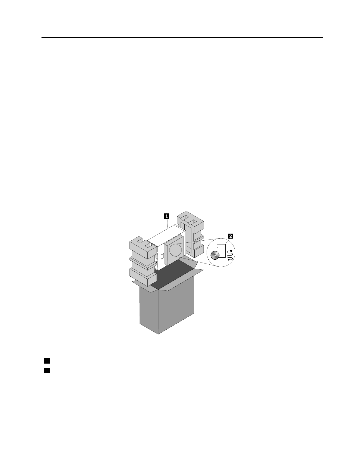
Serverpackage
Theserverpackageincludestheserver,powercords,printeddocumentation,adocumentationDVD,and
softwaremedia.
Note:Dependingonthemodel,yourservermightlookslightlydifferentfromtheillustrationinthistopic.
Figure1.Serverpackage
1Server
2Materialbox(includingpowercords,printeddocumentation,adocumentationDVD,andsoftwaremedia)
Features
Thistopicprovidesgeneralinformationabouttheserverfeaturesforvariousmodels.Dependingonyour
specicmodel,somefeaturesmightvaryornotbeavailable.Forinformationaboutyourspecicmodel,use
theSetupUtilityprogram.See“ViewinginformationintheSetupUtilityprogram”onpage45
©CopyrightLenovo2013
.
7
Page 20

Microprocessor
OneIntel
®
®
Xeon
dual-coreorquad-coremicroprocessor(internalcachesizevariesbymodel)
ForalistofThinkServermicroprocessoroptions,goto:
http://www.lenovo.com/thinkserver
Memory
Yourserverhasfourmemoryslots.Formoreinformation,see“Memorymoduleinstallationrules”onpage72.
Powersupply
Yourservercomeswithoneofthefollowingpowersupplycongurations:
•Onescrew-secured,non-hot-swap450-wattpowersupplyassembly
•Oneortwohot-swap450-wattredundantpowersupplies
Fans
Yourservercomeswiththefollowingfanstoprovidepropersystemcoolingandairow:
•Oneheatsinkandfanassembly
•Twofrontsystemfans
•Onerearsystemfan
Internaldrives
Internaldrivesaredevicesthatyourserverusestoreadandstoredata.Theinternaldrivessupported
byyourservervarybymodel.
•Harddiskdrive
–Fivetoeight3.5-inchhot-swapSerialAdvancedTechnologyAttachment(SATA)orSerialAttached
SCSI(SAS)harddiskdrives(SCSIistheacronymforSmallComputerSystemInterface)
–Uptoeight2.5-inchhot-swapSASharddiskdrivesorSATAsolid-statedrives
–Uptofour3.5-inchhot-swapSATAorSASharddiskdrives
–Uptofour3.5-inchnon-hot-swapSATAharddiskdrives
Notes:
–Theterm“2.5-inchhot-swapharddiskdrives”or“2.5-inchharddiskdrives”hereinafterreferstoallthe
supportedtypesof2.5-inchharddiskdrives,includingthesolid-statedrives.
–ForservermodelswithmorethanfourSATAharddiskdrivesorservermodelsthatuseSASharddisk
drives,theremustbeaRAIDcardinstalled.See“RAIDcard”onpage28.
•Opticaldrive
–Uptotwo5.25-inchSATAopticaldrives
–Theserverhastwoopticaldrivebays.Theloweropticaldrivebayisinstalledwitha5.25-inchSATA
opticaldrive.
Note:Iftheserverhasonlyoneopticaldriveinstalled,ensurethattheopticaldriveisinstalledinthe
lowerbay(opticaldrivebay1).Theupperbayisforasecondaryopticaldriveonly.
Forthelocationinformationabouttheinternaldrivesordrivebays,see“Servercomponents”onpage22
8ThinkServerTS440UserGuide
.
Page 21

Expansionslots
Theserverhasfourexpansionslotsonthesystemboard.Fordetailedinformation,see“Systemboard
components”onpage37.
Input/Output(I/O)features
•OneVideoGraphicsArray(VGA)DB-15connectorontherearpanel
•EightUSBconnectors(twoUSB3.0connectorsonthefrontpanel;fourUSB3.0andtwoUSB2.0
connectorsontherearpanel)
•OneRJ-45Ethernetconnectorontherearpanel
•Oneserialconnectorontherearpanel
Forthelocationinformationabouttheconnectors,refertotherelatedtopicsin“Locations”onpage11
.
Ethernetconnectivity
TheservercomeswithanintegratedIntelGigabitEthernetcontrolleraswellasanEthernetphysicallayer
(PHY)oftheOpenSystemsInterconnectionmodel(OSImodel).Theyprovidetheserverwiththeabilityto
supporttheEthernetconnectorontherearpanelwith10megabitspersecond(Mbps),100Mbps,or1000
Mbpsnetworkconnectivity.Formoreinformation,see“Rearviewoftheserver”onpage16.
Reliability,availability,andserviceability
Reliability,availability,andserviceability(hereinafterreferredtoasRAS)arethreeimportantserverdesign
features.TheRASfeatureshelpyoutoensuretheintegrityofthedatastoredontheserver,theavailabilityof
theserverwhenyouneedit,andtheeasewithwhichyoucandiagnoseandcorrectproblems.
YourserverhasthefollowingRASfeatures:
•Securityfeatures
–Serverlocks(see“Serverlocks”onpage19
)
–Administratorpasswordandpower-onpasswordtohelpprotectunauthorizedaccesstotheserver
(see“Usingpasswords”onpage49)
–ThinkServerTrustedPlatformModule(TPM),whichisasecuritychip,tohelpenhanceserversecurity
–Hot-swapredundantpowersuppliestohelpavoidsignicantinterruptiontotheoperationofthe
systemwhenapowersupplyfails(availableinsomemodels)
•Basicsystemmanagementfeatures
–Abilitytostorethepower-onself-test(POST)hardwaretestresults
–BIOSSetupUtilityprogram
TheBIOSSetupUtilityprogramhelpsyouviewtheserverinformationandconguretheserverinthe
pre-operatingsystemenvironment.See“UsingtheSetupUtilityprogram”onpage45
.
–Hot-swapfeature
Somemodelssupporthot-swapharddiskdrivesandhot-swapredundantpowersupplies.With
thehot-swapfeature,youcaninstall,remove,orreplaceharddiskdrivesorafailingpowersupply
withoutturningofftheserver.
–PrebootExecutionEnvironment(PXE)
TheIntelPXEtechnologyenablesyoutostartyourcomputers,loadanoperatingsystem,ordeploy
executableimagesfromaremoteserverbyusinganetworkinterface.Theoperationcanbedone
independentlyoflocaldatastoragedevices(suchasharddiskdrives)orinstalledoperatingsystems.
Chapter3.Productoverview9
Page 22

–RedundantArrayofIndependentDisks(RAID)
YourserversupportsonboardSATAsoftwareRAID.IfarequiredRAIDcardisinstalled,yourserver
alsosupportsadvancedSATA/SAShardwareRAIDcongurations.Fordetailedinformation,see
“ConguringRAID”onpage55.
–Statuslight-emittingdiodes(LEDs)anddiagnosticLEDs
FormoreinformationabouttheLEDsforyourserver,refertotherelatedtopicsin“Locations”on
page11.
–Softwareprograms
Formoreinformationaboutthesoftwareprograms,see“Software”onpage10.
Specications
Thistopicliststhephysicalspecicationsforyourserver.
Dimensions
Width:195mm(7.68inches)
Height:430mm(16.93inches)withoutfootstands;445mm(17.52inches)withfootstands
Depth:595mm(23.43inches)includingthefrontbezel
Weight
Theproductweightvariesdependingondifferentsystemcongurations.
Rangeofproductweightwithoutpackage:19kg(41.89lb)to28kg(61.73lb)
Rangeofproductpackageweight:2.8kg(6.17lb)to3.5kg(7.72lb)
Environment
•Airtemperature:
Operating:10°Cto35°C(50°Fto95°F)
Storage:-40°Cto70°C(-40°Fto158°F)inoriginalshippingpackage
•Altitude:0to3048m(0to10000ft)
•Humidity:
Operating:10%to80%(non-condensing)
Storage:10%to90%(non-condensing)
Electricalinput
Universalinput:
Minimum:90Vac
Maximum:264Vac
Inputfrequencyrange:47to63Hz
Software
Thistopicprovidesinformationaboutthesoftwareprogramsthatyoucanusetosetup,use,andmaintain
theserver.
ThinkServerEasyStartup
TheThinkServerEasyStartupprogramsimpliestheprocessofconguringRAIDandinstallingsupported
MicrosoftWindowsandLinuxoperatingsystemsanddevicedriversonyourserver.Thisprogramisprovided
10ThinkServerTS440UserGuide
Page 23

withyourserveronaself-starting(bootable)ThinkServerEasyStartupDVD.Theuserguidefortheprogramis
alsoontheDVDandcanbeaccesseddirectlyfromtheprograminterface.Fordetailedinformation,see
“UsingtheThinkServerEasyStartupprogram”onpage52.
ThinkServerEasyUpdateFirmwareUpdater
TheThinkServerEasyUpdateFirmwareUpdaterprogram(hereinafterreferredtoastheFirmwareUpdater
program)enablesyoutomaintainyourserverrmwareuptodateandhelpsyouavoidunnecessaryserver
outages.TheFirmwareUpdaterprogramisprovidedontheLenovoSupportWebsite.Formoreinformation
aboutdownloadingandusingtheFirmwareUpdaterprogram,see“Updatingthermware”onpage60
.
BIOSupdateutilities
TheBIOSrmwarekeepsupdatingaftertheshipmentoftheserver.LenovomaintainspagesontheSupport
WebsiteandprovidestheBIOSupdateutilitieswithinstructionsfordownloadtohelpyouupdatetheBIOSif
needed.Formoreinformation,see“UpdatingorrecoveringtheBIOS”onpage51
rmware”onpage60.
and“Updatingthe
RAIDcongurationutilities
YourserversupportsonboardSATAsoftwareRAID.IfarequiredRAIDcardisinstalled,yourserveralso
supportsadvancedSATA/SAShardwareRAIDcongurations.Fordetailedinformation,see“Conguring
RAID”onpage55
.
Diagnosticprograms
Thefollowingdiagnosticprogramsareavailableforyoutodiagnoseserverproblems:
•ThinkServerDiagnosticTool
•ThinkServerSystemProleCollectionTool
Formoreinformation,see“Usingadiagnosticprogram”onpage145.
Locations
Thistopicprovidesinformationtohelpyoulocateyourservercomponents.
Machinetype,model,andserialnumberlabel
Thistopichelpsyoulocatethetwolabelsthatcontainthemachinetype,model,andserialnumber
informationforyourserver.Thetwolabelsarethesame.Oneisonthefrontbezelandtheotherison
thechassis.
Themachinetype,model,andserialnumberidentifyyourserver.WhenyoucontactLenovoforhelp,the
informationhelpssupporttechnicianstoidentifyyourserverandprovidefasterservice.
Chapter3.Productoverview11
Page 24
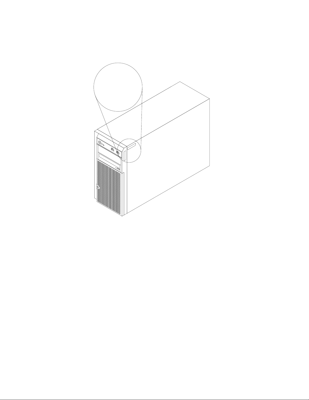
Thefollowingillustrationisasampleofthemachinetype,model,andserialnumberlabelsontheserver.
1
MT-M XXXX -XXX
S/N XXXXXXX
MT-M XXXX -XXX
S/N XXXXXXX
MT-M XXXX -XXX
S/N XXXXXXX
Note:Dependingonthemodel,yourservermightlookslightlydifferentfromtheillustrationinthistopic.
Figure2.Machinetype,model,andserialnumberlabels
12ThinkServerTS440UserGuide
Page 25
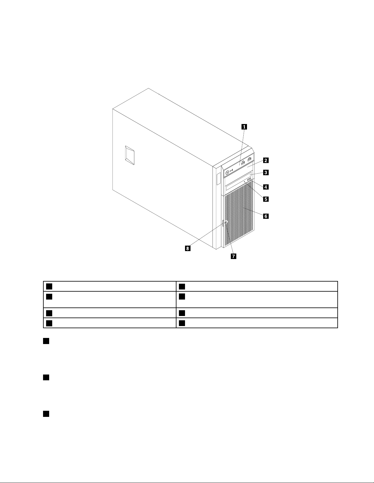
Frontviewoftheserver
Thistopicprovidesinformationtohelpyoulocatethepartsonthefrontoftheserver.
Thefollowingillustrationshowsthefrontviewoftheserver.
Figure3.Frontviewoftheserver
1Frontpanel
2Opticaldrivebay2(withanopticaldriveinstalled
5OpticaldrivestatusLED
6Frontdoor
insomemodels)
3Opticaldrivebay1(withanopticaldriveinstalled)
4Opticaldriveeject/closebutton
1Frontpanel
7Frontdoorlock
8Frontdoorhandle
Fordetailedinformationaboutthecontrol,connectors,andstatusLEDsonthefrontpanel,see“Front
panel”onpage15.
2Opticaldrivebay2
The5.25-inchopticaldrivebay2isforasecondaryopticaldrive.Somemodelshaveasecondaryoptical
driveinstalled.
3Opticaldrivebay1
Yourservercomeswithanopticaldriveinstalledinthe5.25-inchopticaldrivebay1.
Chapter3.Productoverview13
Page 26
4Opticaldriveeject/closebutton
Pressthisbuttontoejectorclosetheopticaldrivewhentheserverpowerison.
5OpticaldrivestatusLED
TheopticaldrivestatusLEDisblinkingingreenwhentheopticaldriveisworkingorinthePOSTprocess.
6Frontdoor
7Frontdoorlock
Youcanlockthefrontdoortoprotecttheharddiskdrivecagesfromunauthorizedaccess.
8Frontdoorhandle
Usethefrontdoorhandletoopenthefrontdoor.
14ThinkServerTS440UserGuide
Page 27
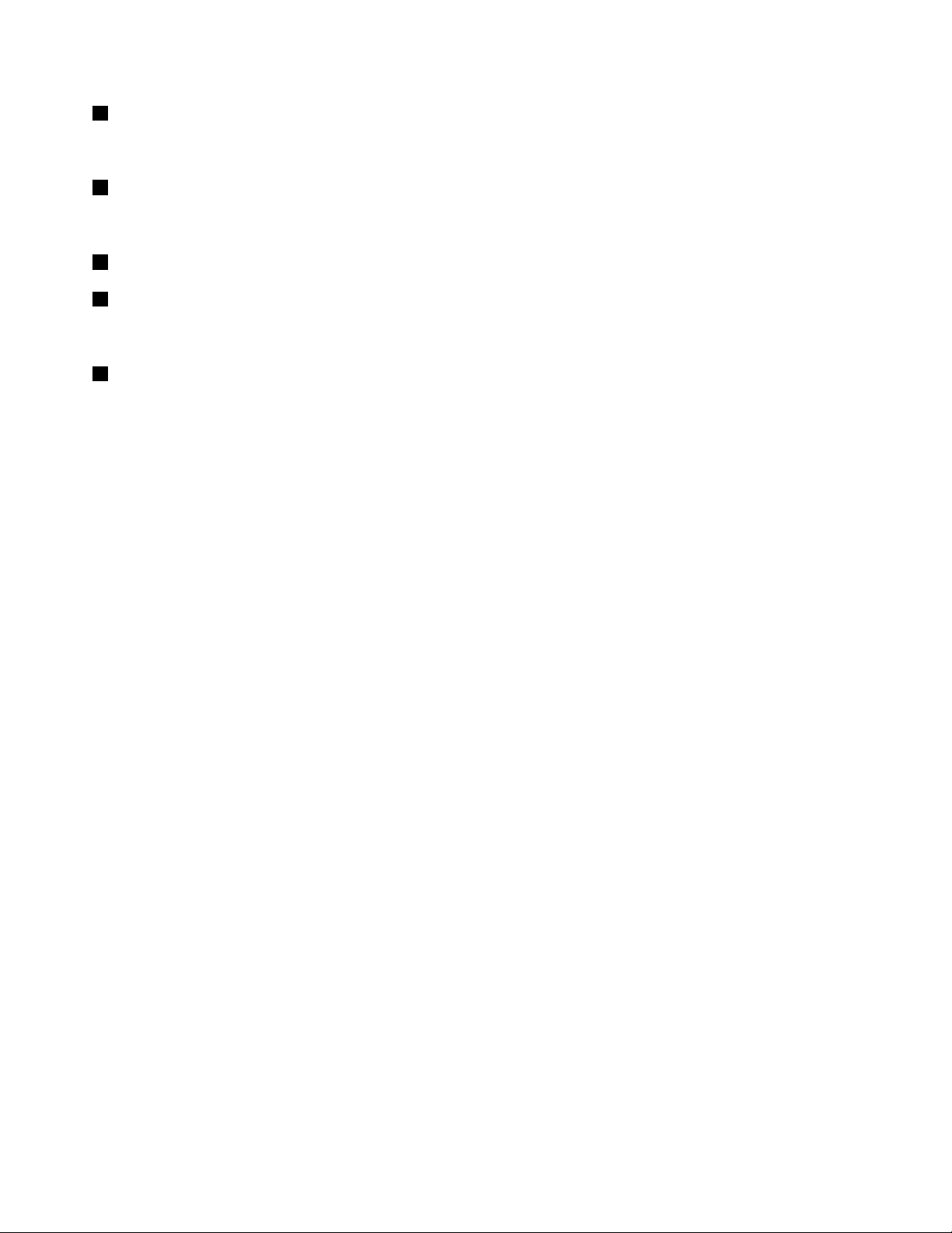
Frontpanel
Thistopicprovidesinformationtohelpyoulocatethecontrol,connectors,andLEDsonthefrontpanelof
theserver.
Thefollowingillustrationshowsthecontrol,connectors,andLEDsonthefrontpaneloftheserver.
Note:Dependingonthemodel,yourservermightlookslightlydifferentfromthefollowingillustration.
Figure4.Frontpanel
1PowerbuttonwithpowerstatusLED
2HarddiskdrivestatusLED
3NetworkInterfaceController(NIC)statusLED
1PowerbuttonwithpowerstatusLED
4FrontUSB3.0connector1
5FrontUSB3.0connector2
Pressthepowerbuttontoturnontheserverwhenyounishsettinguptheserver.Youalsocanholdthe
powerbuttonforseveralsecondstoturnofftheserverifyoucannotturnofftheserverfromtheoperating
system.SeeChapter4“Turningonandturningofftheserver”onpage43.ThepowerstatusLEDhelpsyou
todeterminethecurrentpowerstatus.
Chapter3.Productoverview15
Page 28
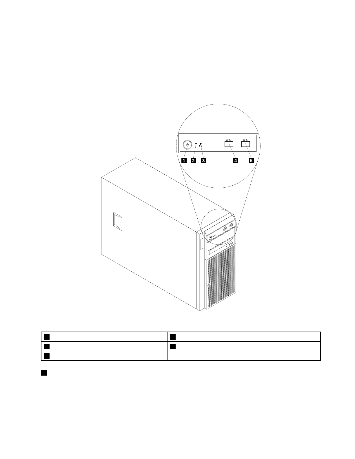
PowerstatusLED
OnGreen
Off
2HarddiskdrivestatusLED
Color
Theserverison.
None
Theserverisoff.
Description
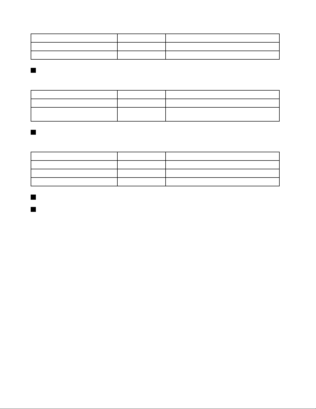
TheharddiskdrivestatusLEDhelpsyoutodeterminethestatusoftheharddiskdriveactivity.
HarddiskdrivestatusLED
3NICstatusLED
Color
Off
Blinking
NoneTheharddiskdriveisnotinuse.
Green
Theharddiskdriveisactiveanddataisbeing
transferred.
Description
TheNICstatusLEDindicatestheLANstatusfortheEthernetconnectorontherearpaneloftheserver.
NICstatusLEDColor
OnGreen
Off
Blinking
4FrontUSB3.0connector1
5FrontUSB3.0connector2
TheserverisconnectedtoaLAN.
None
Green
TheserverisdisconnectedfromaLAN.
TheLANisconnectedandactive.
Description
UsedtoattachaUSB-compatibledevice,suchasaUSBkeyboard,mouse,scanner,orprinter.Ifyouhave
morethaneightUSBdevices,youcanpurchaseaUSBhub,whichyoucanusetoconnectadditional
USBdevices.
Rearviewoftheserver
Thistopicprovidesinformationtohelpyoulocatetheconnectorsandcomponentsontherearofyourserver.
Thefollowingillustrationshowstherearviewoftheserverwithascrew-secured,non-hot-swappower
supplyassembly.
Note:Dependingonthemodel,yourservermightlookslightlydifferentfromtheillustrationsinthistopic.
16ThinkServerTS440UserGuide
Page 29
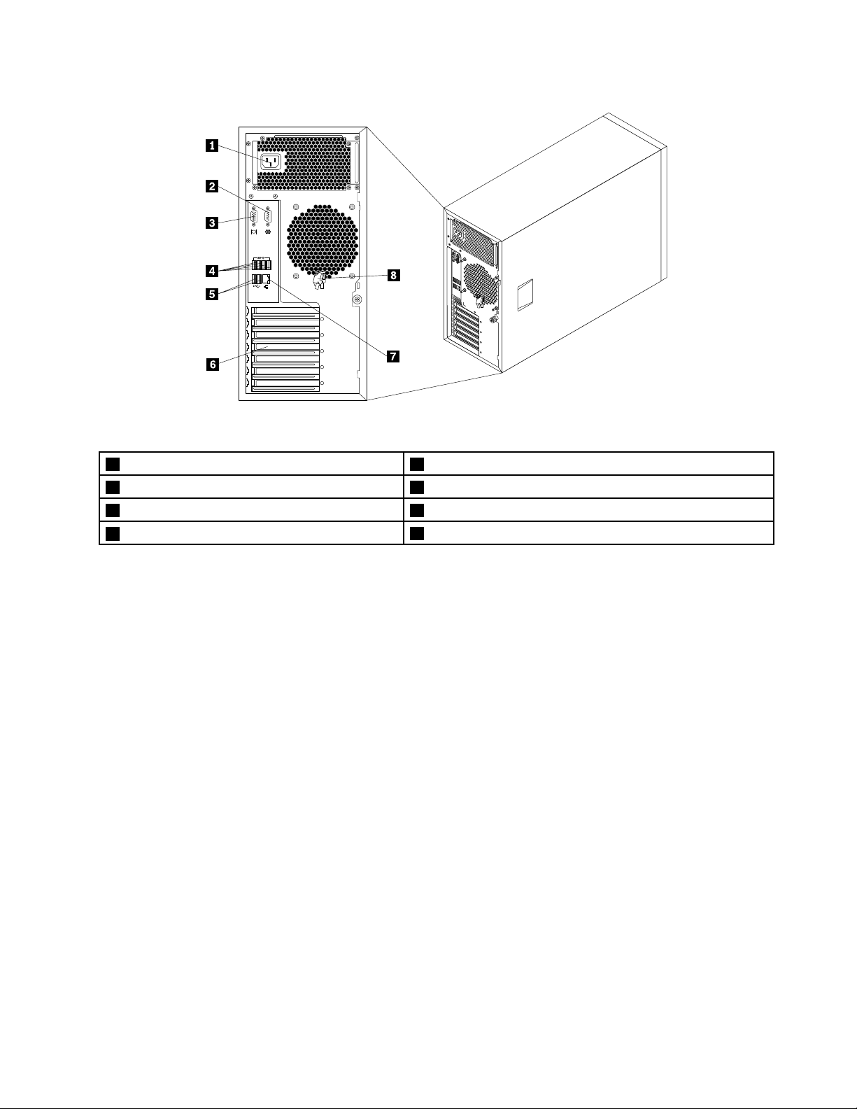
Figure5.Rearviewoftheserverwithanon-hot-swappowersupplyassembly
1Powercordconnector
2Serialconnector
3VGADB-15connector7Ethernetconnector(RJ-45)
4USB3.0connectors(4)
5USB2.0connectors(2)
6Expansioncardarea
8Frontdoorkey
Chapter3.Productoverview17
Page 30
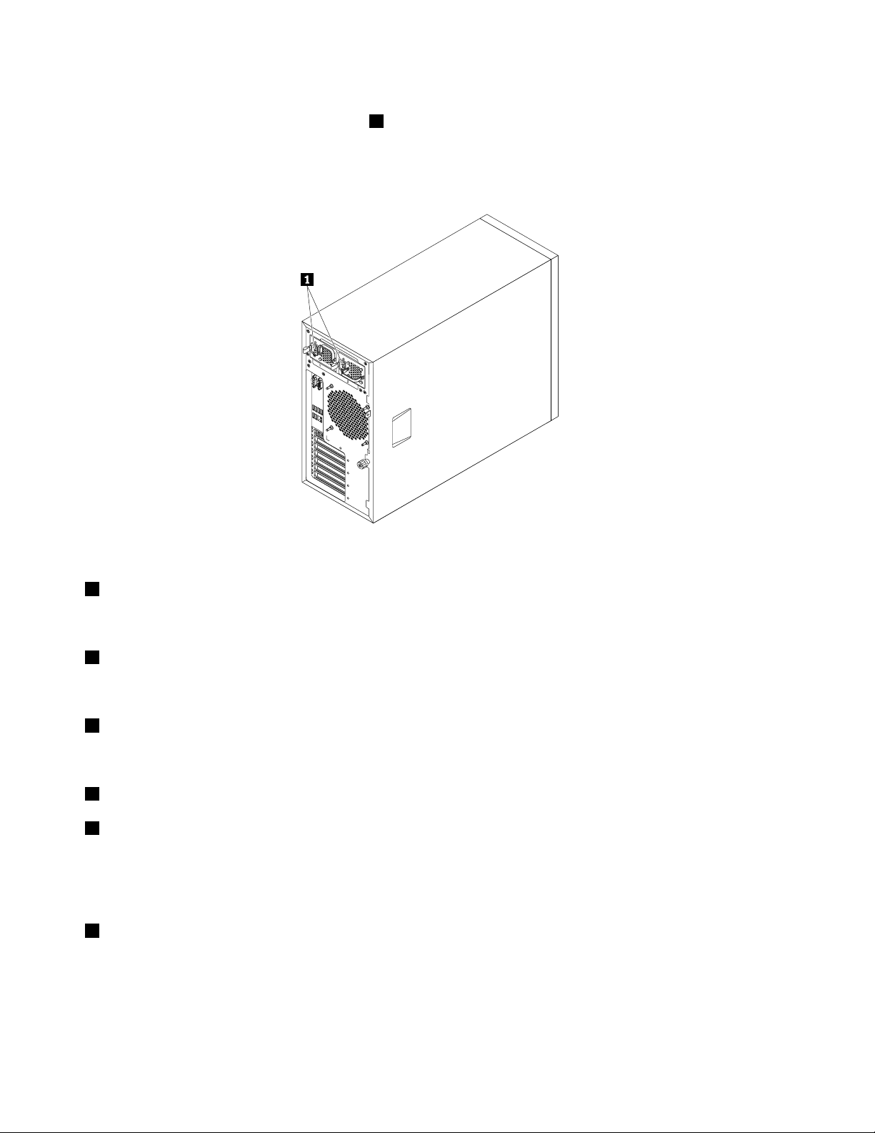
Yourservermodelmighthaveoneortwohot-swapredundantpowersupplies.Eachhot-swapredundant
powersupplyhasonepowercordconnector1ontherearoftheserver.Foreachhot-swapredundantpower
supply,theremightbeoneortwostatusLEDsonthepowersupplynearthepowercordconnector.When
theLEDislitingreen,itindicatesthatthehot-swapredundantpowersupplyisworkingcorrectly.Whenthe
LEDislitinamber,itindicatesthatthehot-swapredundantpowersupplyislikelytofailorhasfailed.
Figure6.Rearviewoftheserverwithhot-swapredundantpowersupplies
1Powercordconnectors
Usedtoconnectthepowercords.
2Serialconnector
Usedtoattachadevicethatusesa9-pinserialconnector.
3VGADB-15connector
UsedtoattachaVGA-compatiblevideodevice,suchasaVGAmonitor.
4USB3.0connectors(4)
5USB2.0connectors(2)
UsedtoattachaUSB-compatibledevice,suchasaUSBkeyboard,mouse,scanner,orprinter.Ifyouhave
morethaneightUSBdevices,youcanpurchaseaUSBhub,whichyoucanusetoconnectadditional
USBdevices.
6Expansioncardarea
YourserverhasfourexpansionslotsonthesystemboardforyoutoinstallappropriatePeripheralComponent
Interconnect(PCI)cardsorPCIExpresscards.Fordetailedinformation,see“Systemboardcomponents”
onpage37.
18ThinkServerTS440UserGuide
Page 31

7Ethernetconnector(RJ-45)
UsedtoattachanEthernetcableforaLAN.TheEthernetconnectorhastwostatusLEDstohelpyouidentify
theEthernetconnectivity,activity,andconnectionspeed.
EthernetstatusLED
2Right
1Left
8Frontdoorkey
ColorStatus
Amber
Amber
GreenOn
None
On
Off
BlinkingTheLANisconnectedandactive.
On
Off
TheserverisconnectedtoaLAN.
TheserverisdisconnectedfromaLAN.
Theconnectionspeedis1000Mbps.
Theconnectionspeedis100Mbps.
Theconnectionspeedis10Mbps.
Description
Usedtoopenorlockthefrontdoor.
Note:Carefullysavethefrontdoorkeytoavoidloss.
Serverlocks
Lockingtheservercoverpreventsunauthorizedaccesstotheinsideofyourserver.Lockingthefrontdoor
preventsunauthorizedaccesstotheinstalledharddiskdrives.
Note:Dependingonthemodel,yourservermightlookslightlydifferentfromtheillustrationsinthistopic.
Chapter3.Productoverview19
Page 32

Padlock
Yourservercomeswithapadlockloop.Whenapadlockisinstalled,theservercovercannotberemoved.
Figure7.Padlock
20ThinkServerTS440UserGuide
Page 33

Kensington-stylecablelock
YoucanuseaKensington-stylecablelocktosecureyourservertoadesk,table,orothernon-permanent
xture.Thecablelockattachestothesecurity-lockslotattherearofyourserverandisoperatedwithakey
orcombinationdependingonthetypeselected.Thecablelockalsolockstheservercover.Thisisthesame
typeoflockusedwithmanynotebookcomputers.YoucanordersuchacablelockdirectlyfromLenovoby
searchingforKensingtonat:
http://www.lenovo.com/support
Figure8.Kensington-stylecablelock
Chapter3.Productoverview21
Page 34

Frontdoorlock
Youcanremovethekeyattachedontherearoftheserveranduseittoopenorlockthefrontdoorofthe
server.Thefrontdoorprotectstheharddiskdrivecagesandpreventsunauthorizedaccesstotheinstalled
harddiskdrives.
Figure9.Frontdoorlock
Servercomponents
Thistopicprovidesinformationtohelpyoulocatethecomponentsofyourserver.Formoreinformation
aboutmajorcomponents,seetherelatedtopicsin“Locations”onpage11.
Toremovetheservercoverandgainaccesstotheinsideoftheserver,see“Removingtheservercover”
onpage65.
Thechassiscongurationvariesbymodel.Thefollowingillustrationsshowthefourmainchassis
congurationsbasedonthesupportedharddiskdrives.
•“Componentsofservermodelswithfour3.5-inchhot-swapharddiskdrivebays”onpage23
•“Componentsofservermodelswitheight3.5-inchhot-swapharddiskdrivebays”onpage24.
•“Componentsofservermodelswitheight2.5-inchhot-swapharddiskdrivebays”onpage25.
•“Componentsofservermodelswithfour3.5-inchnon-hot-swapharddiskdrivebays”onpage26.
Note:Dependingonthemodel,yourservermightlookslightlydifferentfromtheillustrationsinthistopic.
22ThinkServerTS440UserGuide
.
Page 35

Componentsofservermodelswithfour3.5-inchhot-swapharddiskdrivebays
Figure10.Componentsofservermodelswithfour3.5-inchhot-swapharddiskdrivebays
1Coverpresenceswitch
2Powerconversionboard
3Frontpanel
4Opticaldrivebay2(withanopticaldriveinstalled
11Frontsystemfan2
12Systemboard
13Low-prolePCIcardbracket
14MainPCIcardbracket
insomemodels)
5Opticaldrivebay1(withanopticaldriveinstalled)15Systemboardbattery
6Harddiskdrivebay316Expansioncard
7Harddiskdrivebay2
8Harddiskdrivebay1
9Harddiskdrivebay019Powersupply
10Frontsystemfan1
17Heatsinkandfanassembly
18Rearsystemfan
20Fourmemoryslots(installedmemorymodulesvaryby
model)
Note:Thepowerconversionboard2,low-prolePCIcardbracket13,andmainPCIcardbracket14are
availableinservermodelsthatcomewithaRAIDcard.
Chapter3.Productoverview23
Page 36

Componentsofservermodelswitheight3.5-inchhot-swapharddiskdrivebays
Figure11.Componentsofservermodelswitheight3.5-inchhot-swapharddiskdrivebays
1Coverpresenceswitch
2Powerconversionboard
3Frontpanel
4Opticaldrivebay2(withanopticaldriveinstalled
13Harddiskdrivebay0
14Frontsystemfan1
15Frontsystemfan2
16Systemboard
insomemodels)
5Opticaldrivebay1(withanopticaldriveinstalled)17Systemboardbattery
6Harddiskdrivebay7
7Harddiskdrivebay6
8Harddiskdrivebay520Expansioncard
9Harddiskdrivebay4
10Harddiskdrivebay3
11Harddiskdrivebay223Powersupply
12Harddiskdrivebay1
18MainPCIcardbracket
19Low-prolePCIcardbracket
21Heatsinkandfanassembly
22Rearsystemfan
24Fourmemoryslots(installedmemorymodulesvaryby
model)
Note:Thepowerconversionboard2,low-prolePCIcardbracket19,andmainPCIcardbracket18are
availableinservermodelsthatcomewithaRAIDcard.
24ThinkServerTS440UserGuide
Page 37

Componentsofservermodelswitheight2.5-inchhot-swapharddiskdrivebays
Figure12.Componentsofservermodelswitheight2.5-inchhot-swapharddiskdrivebays
1Coverpresenceswitch
2Powerconversionboard
3Frontpanel
4Opticaldrivebay2(withanopticaldriveinstalled
13Harddiskdrivebay0
14Frontsystemfan1
15Frontsystemfan2
16Systemboard
insomemodels)
5Opticaldrivebay1(withanopticaldriveinstalled)17Systemboardbattery
6Harddiskdrivebay7
7Harddiskdrivebay6
8Harddiskdrivebay520Expansioncard
9Harddiskdrivebay4
10Harddiskdrivebay3
11Harddiskdrivebay223Powersupply
12Harddiskdrivebay1
18Low-prolePCIcardbracket
19MainPCIcardbracket
21Heatsinkandfanassembly
22Rearsystemfan
24Fourmemoryslots(installedmemorymodulesvaryby
model)
Note:Thepowerconversionboard2,low-prolePCIcardbracket18,andmainPCIcardbracket19are
availableinservermodelsthatcomewithaRAIDcard.
Chapter3.Productoverview25
Page 38

Componentsofservermodelswithfour3.5-inchnon-hot-swapharddiskdrivebays
Figure13.Componentsofservermodelswithfour3.5-inchnon-hot-swapharddiskdrivebays
1Coverpresenceswitch
2Powerconversionboard
3Frontpanel
4Opticaldrivebay2(withanopticaldriveinstalled
11Frontsystemfan2
12Systemboard
13Systemboardbattery
14Low-prolePCIcardbracket
insomemodels)
5Opticaldrivebay1(withanopticaldriveinstalled)15MainPCIcardbracket
6Harddiskdrivebay316Expansioncard
7Harddiskdrivebay2
8Harddiskdrivebay1
9Harddiskdrivebay019Powersupply
10Frontsystemfan1
17Heatsinkandfanassembly
18Rearsystemfan
20Fourmemoryslots(installedmemorymodulesvaryby
model)
Note:Thepowerconversionboard2,low-prolePCIcardbracket14,andmainPCIcardbracket15are
availableinservermodelsthatcomewithaRAIDcard.
Hot-swapharddiskdrivestatusLEDs
Thistopicappliesonlytoservermodelswithhot-swapharddiskdrives.
26ThinkServerTS440UserGuide
Page 39

Note:Dependingonthemodel,yourservermightlookslightlydifferentfromtheillustrationsinthistopic.
Eachhot-swapharddiskdrivehastwostatusLEDsonthefront.Unlockandopenthefrontdoortoaccess
theharddiskdrivesandviewthestatusLEDs.
Figure14.3.5-inchhot-swapharddiskdrivestatusLEDs
Chapter3.Productoverview27
Page 40

Figure15.2.5-inchhot-swapharddiskdrivestatusLEDs
1HarddiskdriveactivityLED2HarddiskdriveRAIDstatusLEDDescription
OffOff
On,greenOff
Blinking,green
On,greenBlinkingrapidly(aboutfourashes
On,greenOn,amber
Blinking,green
Off
persecond),amber
Blinkingslowly(aboutoneashper
second),amber
Theharddiskdrivehasfailedoris
notpresent.
Theharddiskdriveispresentbutnot
inuse.
Theharddiskdriveisactiveanddata
isbeingtransferred.
TheRAIDcontrollerislocatingthe
harddiskdrive.
TheRAIDarrayhasfailedandcannot
recover.
Theharddiskdriveisbeingrebuilt.
RAIDcard
ThistopicprovidesinformationtohelpyoulocatetheconnectorsonaRAIDcardifaRAIDcardisinstalledin
thePCI-Eslot1onthesystemboard.See“Systemboardcomponents”onpage37.
28ThinkServerTS440UserGuide
Page 41

SomeservermodelscomewitharequiredRAIDcardtoprovideadvancedSATA/SAShardwareRAID
functionstotheserver.IfyourserverdoesnotcomewithaRAIDcard,youcanpurchaseonefromLenovo.
See“InstallingorremovingtheRAIDcard”onpage80.
Notes:
•TheoptionkitfortheRAIDcardisdesignedfordifferenttypesofserversandmightcontainadditional
cablesthatarenotrequiredforyourserver.
•ForservermodelswithmorethanfourSATAharddiskdrivesormodelsthatuseSASharddiskdrives,
theremustbeaRAIDcardinstalled.
YourserversupportsthefollowingRAIDcards:
•ThinkServerRAID500Adapter(alsoknownasThinkServer9240-8iRAID0/1Adapter)
•ThinkServerRAID700Adapter(alsoknownasThinkServer9260-8iSASRAIDAdapter)
ThinkServerRAID500Adapter(alsoknownasThinkServer9240-8iRAID0/1Adapter)
ThefollowingillustrationshowstheconnectorsontheThinkServerRAID500Adapter.
Figure16.ThinkServerRAID500Adapter
1Port03TR500keyconnector
2Port1
1Port0
Usedtoconnectamini-SASsignalcable.See“Connectingthecables”onpage34.
2Port1
Usedtoconnectamini-SASsignalcable.See“Connectingthecables”onpage34.
3TR500keyconnector
UsedtoconnectaThinkServerRAID500UpgradeKeyforAdvancedRAID.See“Installingorremovingthe
ThinkServerRAID500UpgradeKeyforAdvancedRAID”onpage82
.
Chapter3.Productoverview29
Page 42

ThinkServerRAID700Adapter(alsoknownasThinkServer9260-8iSASRAIDAdapter)
ThefollowingillustrationshowstheconnectorsontheThinkServerRAID700Adapter.
Figure17.ThinkServerRAID700Adapter
1Ports7-4
2Ports3-0
1Ports7-4
3ThinkServerRAID700Batteryconnector
Usedtoconnectamini-SASsignalcable.See“Connectingthecables”onpage34.
2Ports3-0
Usedtoconnectamini-SASsignalcable.See“Connectingthecables”onpage34.
3ThinkServerRAID700Batteryconnector
UsedtoconnectaThinkServerRAID700Battery.See“InstallingorremovingtheThinkServerRAID700
Battery”onpage86
.
Hot-swapharddiskdrivebackplane
Yourservermightcomewithoneofthefollowinghot-swapharddiskdriveandbackplanecongurations:
•Fivetoeight3.5-inchhot-swapSATAorSASharddiskdriveswithtwobackplanes
•Uptofour3.5-inchhot-swapSATAorSASharddiskdriveswithonebackplane
•Uptoeight2.5-inchhot-swapSASharddiskdriveswithonebackplane
30ThinkServerTS440UserGuide
Page 43

Thefollowingillustrationshowsthelocationsofthehot-swapharddiskdrivebackplanes1.Youneedto
opentheservercoverandremovethefrontsystemfanstoaccessthebackplanes.See“Removingthe
servercover”onpage65and“Replacingthefrontsystemfan1”onpage128.
Notes:
•Dependingonthemodel,yourservermightlookslightlydifferentfromtheillustrationinthistopic.
•Thefollowingillustrationisbasedonservermodelsthathavevetoeight3.5-inchhot-swapSATAorSAS
harddiskdriveswithtwobackplanes.
Figure18.Hot-swapharddiskdrivebackplanelocations
Backplaneforservermodelswithfour3.5-inchhot-swapharddiskdrivebays
Thistopicprovidesinformationtohelpyoulocatetheconnectorsonthebackplaneforservermodels
withfour3.5-inchhot-swapharddiskdrivebays.
Chapter3.Productoverview31
Page 44

Thefollowingillustrationsshowtheconnectorsonthebackplaneforservermodelswithfour3.5-inch
hot-swapharddiskdrivebays.
Figure19.Frontviewofthebackplaneforservermodelswithfour3.5-inchhot-swapharddiskdrivebays
1Slot0fora3.5-inchSATAorSAShot-swaphard
3Slot2fora3.5-inchSATAorSAShot-swapharddiskdrive
diskdrive
2Slot1fora3.5-inchSATAorSAShot-swaphard
4Slot3fora3.5-inchSATAorSAShot-swapharddiskdrive
diskdrive
Figure20.Rearviewofthebackplaneforservermodelswithfour3.5-inchhot-swapharddiskdrivebays
18-pinpowerconnector
Usedtoconnectapowercable.
2Mini-SASsignalcableconnector
Usedtoconnectthemini-SASconnectorononeendofthemini-SASsignalcable.
32ThinkServerTS440UserGuide
Page 45

Backplaneforservermodelswitheight2.5-inchhot-swapharddiskdrivebays
Thistopicprovidesinformationtohelpyoulocatetheconnectorsonthebackplaneforservermodels
witheight2.5-inchhot-swapharddiskdrivebays.
Thefollowingillustrationsshowtheconnectorsonthebackplaneforservermodelswitheight2.5-inch
hot-swapharddiskdrivebays.
Figure21.Frontviewofthebackplaneforservermodelswitheight2.5-inchhot-swapharddiskdrivebays
1Slot0fora2.5-inchSAShot-swapharddisk
drive
2Slot1fora2.5-inchSAShot-swapharddisk
drive
3Slot2fora2.5-inchSAShot-swapharddisk
drive
4Slot3fora2.5-inchSAShot-swapharddisk
drive
5Slot4fora2.5-inchSAShot-swapharddiskdrive
6Slot5fora2.5-inchSAShot-swapharddiskdrive
7Slot6fora2.5-inchSAShot-swapharddiskdrive
8Slot7fora2.5-inchSAShot-swapharddiskdrive
Figure22.Rearviewofthebackplaneforservermodelswitheight2.5-inchhot-swapharddiskdrivebays
18-pinpowerconnector
Usedtoconnectapowercable.
Chapter3.Productoverview33
Page 46

2Mini-SASsignalcableconnector1
Usedtoconnectthemini-SASconnectorononeendofthemini-SASsignalcable.
3Mini-SASsignalcableconnector0
Usedtoconnectthemini-SASconnectorononeendofthemini-SASsignalcable.
Connectingthecables
Thistopicprovidesinstructionsonthefollowingcableconnections:
•“Connectingthemini-SASsignalcablefromthesystemboardtothebackplaneforservermodelswith
hot-swapharddiskdrives”onpage34
•“Connectingthemini-SASsignalcablesfromtheRAIDcardtothebackplanesforservermodelswith
hot-swapharddiskdrives”onpage35.
•“ConnectingtheSATAsignalcablesfromthesystemboardtothenon-hot-swapharddiskdrives”
onpage37.
Connectingthemini-SASsignalcablefromthesystemboardtothebackplanefor
servermodelswithhot-swapharddiskdrives
Forservermodelswithuptofour3.5-inchSATAhot-swapharddiskdrivesinstalled,youcanusethe
mini-SASsignalcablethathasfourSATAconnectorsandoneSerialGeneralPurposeInput/Output(SGPIO)
connectorforcableconnection.
.
Toconnectthemini-SASsignalcablefromthesystemboardtothebackplane,dothefollowing:
1.Connectthemini-SASconnector1tothemini-SASsignalcableconnector0onthebackplane.The
backplaneisinstalledonthelowerharddiskdrivecage.
2.ConnectthefourSATAconnectors3-6totheSATAconnectors0-3onthesystemboard.
3.ConnecttheSGPIOconnector2totheSATASGPIOconnectoronthesystemboard.
Figure23.Mini-SASsignalcablewithfourSAT AconnectorsandoneSATASGPIOconnector
Toconnectthepowercablefromthesystemboardtothebackplane,connectthe4-pinpowerconnectoron
oneendofthepowercabletothe4-pinpowerconnectoronthesystemboard.Then,connecttheother
powerconnectorontheotherendofthepowercabletothepowerconnectoronthebackplane.
34ThinkServerTS440UserGuide
Page 47

Note:ThenumberonthelabelforeachofthefourSATAsignalcablesindicatesthesequencetofollow
whenyouareconnectingthecablestothecorrespondingSATAconnectors(0-3)onthesystemboard.
SATAsignalcablelabelSystemboardSA TAconnector
P0
P1
P2
P3
SATAconnector0
SATAconnector1
SATAconnector2
SATAconnector3
ForinformationaboutconguringRAIDusingthecongurationutilityfortheThinkServerRAID100,see
“ConguringthesystemBIOStoenableonboardSATARAIDfunctionality”onpage57.
Refertothefollowingtopicsforinformationabouttheconnectorlocations:
•“Hot-swapharddiskdrivebackplane”onpage30
•“Systemboardcomponents”onpage37
Connectingthemini-SASsignalcablesfromtheRAIDcardtothebackplanesfor
servermodelswithhot-swapharddiskdrives
IfyourserverhasasupportedRAIDcardinstalled,youcanconnectthemini-SASsignalcablesfromthe
RAIDcardtothebackplanestosupportuptoeightharddiskdrives.Inthiscase,youcancongureRAIDfor
theharddiskdrivesusingtheadvancedhardwareRAIDfunctions.
Note:TheoptionpackagefortheRAIDcardisdesignedfordifferenttypesofserversandmightcontain
additionalcablesthatarenotrequiredforinstallation.
Chapter3.Productoverview35
Page 48

Figure24.ConnectingcablesfromtheRAIDcardtothebackplanes
Toconnectthemini-SASsignalcablesfromtheRAIDcardtothebackplanes,dothefollowing:
•IfyouareusingaThinkServerRAID700Adapter,dothefollowing:
1.Useonemini-SAStomini-SASsignalcable.Connectthemini-SASconnector3ononeendofthe
cabletotheports3-0ontheRAIDcard.Then,connectthemini-SASconnector
4ontheother
endofthecabletothemini-SASsignalcableconnector0onthebackplanefor2.5-inchharddisk
drivesortothemini-SASsignalcableconnectoronthebackplanefor3.5-inchharddiskdrives.The
backplanefor3.5-inchharddiskdrivesisinstalledonthelowerharddiskdrivecage.
2.Ifyourserverhasmorethanfourharddiskdrivesinstalled,usetheothermini-SAStomini-SASsignal
cable.Connectthemini-SASconnector
1ononeendofthecabletotheports7-4ontheRAID
card.Then,connectthemini-SASconnector2ontheotherendofthecabletothemini-SASsignal
cableconnector1onthebackplanefor2.5-inchharddiskdrivesortothemini-SASsignalcable
connectoronthebackplanefor3.5-inchharddiskdrives.Thebackplanefor3.5-inchharddiskdrives
isinstalledontheupperharddiskdrivecage.
•IfyouareusingaThinkServerRAID500Adapter,dothefollowing:
1.Useonemini-SAStomini-SASsignalcable.Connectthemini-SASconnector1ononeendofthe
cabletotheport0ontheRAIDcard.Then,connectthemini-SASconnector2ontheotherendof
thecabletothemini-SASsignalcableconnector0onthebackplanefor2.5-inchharddiskdrivesor
tothemini-SASsignalcableconnectoronthebackplanefor3.5-inchharddiskdrives.Thebackplane
for3.5-inchharddiskdrivesisinstalledonthelowerharddiskdrivecage.
2.Ifyourserverhasmorethanfourharddiskdrivesinstalled,usetheothermini-SAStomini-SASsignal
cable.Connectthemini-SASconnector3ononeendofthecabletotheport1ontheRAIDcard.
Then,connectthemini-SASconnector4ontheotherendofthecabletothemini-SASsignal
cableconnector1onthebackplanefor2.5-inchharddiskdrivesortothemini-SASsignalcable
connectoronthebackplanefor3.5-inchharddiskdrives.Thebackplanefor3.5-inchharddiskdrives
isinstalledontheupperharddiskdrivecage.
Note:ThelocationoftheexternalconnectorontheRAIDcarddiffersdependingonthetypeofRAIDcard.
36ThinkServerTS440UserGuide
Page 49

Toconnectthepowercables,dothefollowing:
•Forservermodelswithuptofour3.5-inchhot-swapharddiskdrives,connectthe4-pinpowerconnector
ononeendofthepowercabletothe4-pinpowerconnectoronthesystemboard.Then,connectthe
otherpowerconnectorontheotherendofthepowercabletothepowerconnectoronthebackplane.
•Forservermodelswithmorethanfour3.5-inchhot-swapharddiskdrives,usetwopowercables.
Connectthe4-pinpowerconnectorononeendofonepowercabletothe4-pinpowerconnectoron
thesystemboard.Then,connecttheotherpowerconnectorontheotherendofthepowercabletothe
powerconnectoronthebackplaneinstalledontheupperharddiskdrivecage.Connectthe8-pinpower
connectorononeendoftheotherpowercabletothe8-pinpowerconnectoronthepowerconversion
board.Then,connecttheotherpowerconnectorontheotherendofthepowercabletothepower
connectoronthebackplaneinstalledonthelowerharddiskdrivecage.
•Forservermodelswithuptoeight2.5-inchhot-swapharddiskdrives,connectthe8-pinpowerconnector
ononeendofthepowercabletothe8-pinpowerconnectoronthepowerconversionboard.Then,
connecttheotherpowerconnectorontheotherendofthepowercabletothepowerconnectoronthe
backplane.
Refertothefollowingtopicsforinformationabouttheconnectorlocations:
•“Hot-swapharddiskdrivebackplane”onpage30
•“RAIDcard”onpage28
•“Systemboardcomponents”onpage37
ConnectingtheSAT Asignalcablesfromthesystemboardtothenon-hot-swap
harddiskdrives
Forservermodelswithuptofour3.5-inchnon-hot-swapharddiskdrives,connectoneendofaSATAsignal
cabletotherearofanon-hot-swapharddiskdrive.Then,connecttheotherendoftheSATAsignalcable
totheappropriateSATAconnectoronthesystemboard.Youalsoneedtoconnecttheappropriatepower
connectortotherearofthenon-hot-swapharddiskdrive.
ThefollowingtableprovidesinformationabouttherecommendedSATAconnectoronthesystemboardfor
thenon-hot-swapharddiskdriveinstalledineachdrivebay.
Non-hot-swapharddiskdrive
Installedinbay0
Installedinbay1
Installedinbay2
Installedinbay3
SATAconnector0
SATAconnector1
SATAconnector2
SATAconnector3
SATAconnectoronthesystemboard
Toconnectthepowercablefromthesystemboardtothenon-hot-swapharddiskdrives,connectthe4-pin
powerconnectorononeendofthepowercabletothe4-pinpowerconnectoronthesystemboard.Then,
connectthepowerconnectorsontheotherendofthepowercabletothecorrespondingpowerconnectors
ontheharddiskdrives.
Formoreinformationaboutthelocationoftheharddiskdrivebays,powerconnectors,andSATAconnectors
onthesystemboard,see“Servercomponents”onpage22and“Systemboardcomponents”onpage37
Systemboardcomponents
Thefollowingillustrationshowsthecomponentlocationsonthesystemboard.
Chapter3.Productoverview37
Page 50

31
33
32
Figure25.Systemboardcomponents
14-pinpowerconnector
2Systemboardbattery19Systemfan1connector
3Microprocessorsocket20Frontpanelconnector
4Microprocessorfanconnector
5Memoryslot1(DIMM1)22PlatformControllerHub(PCH)
6Memoryslot2(DIMM2)23SATASGPIOconnector
7Memoryslot3(DIMM3)24USB2.0connector
8Memoryslot4(DIMM4)25ClearCMOS(ComplementaryMetalOxideSemiconductor)
18SATAconnector2
21FrontUSB3.0connector
jumper
9Thermalsensorconnector
10Systemfan2connector27Serialconnector
114-pinpowerconnector
124-pinpowerconnector
13Mainpowerconnector
14SATAconnector331PCIExpressx16cardslot(PCI-Eslot1)
15SATAconnector0
16SATAconnector433Coverpresenceswitchconnector(intrusionswitchconnector)
17SATAconnector1
26ManagementEngine(ME)disablejumper
28PCIcardslot(PCIslot4)
29PCIExpressx4cardslot(PCI-Eslot3)
30PCIExpressx1cardslot(PCI-Eslot2)
32Rearsystemfanconnector
38ThinkServerTS440UserGuide
Page 51

14-pinpowerconnector
Usedtoconnectthepowercablefromthepowersupply.
2Systemboardbattery
Yourserverhasaspecialtypeofmemorythatmaintainsthedate,time,andcongurationinformationfor
built-infeatures.Thesystemboardbatterykeepstheinformationactivewhenyouturnofftheserver.
3Microprocessorsocket
Themicroprocessorissecuredinthemicroprocessorsocketonthesystemboard.Aheatsinkandfan
assemblyisinstalledabovethemicroprocessortoprovidecooling.
4Microprocessorfanconnector
Usedtoconnectthecableoftheheatsinkandfanassembly.
5-8Memoryslots
Yourserversystemboardprovidesfourmemoryslotstosupportuptofourmemorymodules.Formore
information,see“Memorymoduleinstallationrules”onpage72.
9Thermalsensorconnector
Usedtoconnectthethermalsensorcable.
10Systemfan2connector
Usedtoconnectthecableoftheupperfrontsystemfan(frontsystemfan2).
114-pinpowerconnector
Usedtoconnectthepowercableforopticaldrives.
124-pinpowerconnector
Usedtoconnectthepowercableforharddiskdrives.
13Mainpowerconnector
Usedtoconnectthe14-pinpowerconnectorofthepowersupplytoprovidemainpowertoyourserver.
1415161718SATAconnectors
UsedtoconnectSATAsignalcablesfortheSATAharddiskdrivesorSATAopticaldrives.
Notes:
•IfyourserverhasoneSATAopticaldriveinstalled,useaSATAsignalcabletoconnecttheopticaldrive
totheSATAconnector4onthesystemboard.
•IfyourserverhastwoSATAopticaldrivesinstalled,usetwoSATAsignalcablestoconnecttheoptical
drivestotheSATAconnector4andSATAconnector3onthesystemboardrespectively.
Chapter3.Productoverview39
Page 52

19Systemfan1connector
Usedtoconnectthecableofthelowerfrontsystemfan(frontsystemfan1).
20Frontpanelconnector
Usedtoconnectthefrontpanelcable.
21FrontUSB3.0connector
UsedtoconnectthefrontUSBcable.
22PlatformControllerHub(PCH)
Thischipprovidesthedatabufferingandinterfacearbitrationrequiredtoensurethatsysteminterfaces
operateefcientlyandprovidesthebandwidthnecessaryforthesystemtoachievepeakperformance.
23SA TASGPIOconnector
UsedtoconnecttheSGPIOconnectorofthemini-SASsignalcablewithfourSATAconnectorsandone
SGPIOconnectortoenabletheRAIDstatusLEDsforhot-swapharddiskdrives.
24InternalUSB2.0connector
Reservedforthemanufacturer.
40ThinkServerTS440UserGuide
Page 53

25ClearCMOS(ComplementaryMetalOxideSemiconductor)jumper
UsedtoclearCMOSandturntheBIOSsettingsintothefactorydefaultsettings.
Note:ClearingCMOSdoesnoteraseyourBIOSpasswords.
Ajumperisashortlengthofconductorusedtosetuporadjustaprintedcircuitboard,suchasthesystem
boardofacomputer.Ajumperusuallyisencasedinanon-conductiveblockofplasticforconvenientuse
andtoavoidanypossibledamagetoalivecircuit.Jumperpinsarrangedingroupsonthesystemboardare
calledjumperblocks.Whentwoormorejumperpinsarecappedwithajumper,anelectricalconnectionis
madebetweenthemandtheequipmentisthusinstructedtoactivatecertainsettingsaccordingly.
ToclearCMOS,dothefollowing:
1.Removeallmediafromthedrivesandturnoffallattacheddevicesandtheserver.Then,disconnectall
powercordsfromelectricaloutletsanddisconnectallcablesthatareconnectedtotheserver.
2.Removetheservercover.See“Removingtheservercover”onpage65.
3.Laytheserveronitssideforeasieroperation.
4.LocatetheClearCMOSjumperonthesystemboard.
5.MovetheClearCMOSjumperfromthedefaultnormalposition(pin1andpin2)totheshort-circuited
position(pin2andpin3).
6.Reconnecttheservertoanacpowersourceandturnontheserver.Then,waitmorethan10seconds.
7.Whenyouhearbeeps,turnofftheserver.Then,movetheClearCMOSjumperbacktothenormal
position(pin1andpin2).
8.Reinstalltheservercoverandconnectthepowercords.See“Completingthepartsreplacement”on
page141
.
9.Connecttheservertoanacpowersourceandturnontheserver.TheclearingCMOSprocessis
completed.
26ManagementEngine(ME)disablejumper
UsethisjumpertodisabletheME.
TodisabletheME,dothefollowing:
1.Removeallmediafromthedrivesandturnoffallattacheddevicesandtheserver.Then,disconnectall
powercordsfromelectricaloutletsanddisconnectallcablesthatareconnectedtotheserver.
2.Removetheservercover.See“Removingtheservercover”onpage65.
3.Laytheserveronitssideforeasieroperation.
4.LocatetheMEdisablejumperonthesystemboard,andthenensurethatthejumperisencasedina
non-conductiveblockofplastic.
5.Reinstalltheservercoverandconnectthepowercords.See“Completingthepartsreplacement”on
page141.
6.Connecttheservertoanacpowersource.Then,turnontheserver.TheMEhasbeendisabled.
27Serialconnector
Usedtoprovideanoptionalserialconnectorsolutionwitharequiredcable.
28PCIcardslot(PCIslot4)
Usedtoinstallastandard32-bit33-MHzPCIcardwith167mm(6.57inches)inlength.
Chapter3.Productoverview41
Page 54

29PCIExpressx4cardslot(PCI-Eslot3)
ThisPCIcardslotsupportsaPCIExpressx4cardwith167mm(6.57inches)inlength,suchasagraphics
card.
30PCIExpressx1cardslot(PCI-Eslot2)
ThisPCIcardslotsupportsaPCIExpressx1cardwith167mm(6.57inches)inlength,suchasanEthernet
card.
31PCIExpressx16cardslot(PCI-Eslot1)
ThisPCIcardslotsupportsaPCIExpressx16cardwith167mm(6.57inches)inlength,suchasaRAIDcard.
32Rearsystemfanconnector
Usedtoconnectthecableoftherearsystemfan.
33Coverpresenceswitchconnector(intrusionswitchconnector)
Usedtoconnectthecableofthecoverpresenceswitch.
42ThinkServerTS440UserGuide
Page 55

Chapter4.Turningonandturningofftheserver
Thischapterprovidesinformationaboutturningonandturningofftheserver.
Turningontheserver
Afteryounishunpackingandsettinguptheserver,connectittoanacpowersource.Pressthepower
buttononthefrontpaneltoturnontheserver.See“Frontpanel”onpage15.
Turningofftheserver
CAUTION:
Thepowercontrolbuttononthedeviceandthepowerswitchonthepowersupplydonotturnoff
theelectricalcurrentsuppliedtothedevice.Thedevicealsomighthavemorethanonepower
cord.Toremoveallelectricalcurrentfromthedevice,ensurethatallpowercordsaredisconnected
fromthepowersource.
Theservercanbeturnedoffinoneofthefollowingways:
•Turnofftheserverfromtheoperatingsystemifyouroperatingsystemsupportsthisfeature.Afteran
orderlyshutdownoftheoperatingsystem,theserverwillturnoffautomatically.Forinstructionsonhow
toshutdownyourspecicoperatingsystem,refertotherelateddocumentationorhelpsystemfor
theoperatingsystem.
•Pressthepowerbuttononthefrontpaneltostartanorderlyshutdownoftheoperatingsystemandturn
offtheserver,ifyouroperatingsystemsupportsthisfeature.
•Ifyourserverstopsrespondingandyoucannotturnitoff,pressandholdthepowerbuttononthe
frontpanelforfoursecondsormore.Ifyoustillcannotturnofftheserver,disconnectallpowercords
fromtheserver.
•Theservermightbeturnedoffasanautomaticresponsetoacriticalsystemfailure.
Note:Forinformationaboutyourspecicoperatingsystem,refertotherelateddocumentationorhelp
systemfortheoperatingsystem.
©CopyrightLenovo2013
43
Page 56

44ThinkServerTS440UserGuide
Page 57

Chapter5.Conguringtheserver
Thischapterprovidesthefollowinginformationtohelpyouconguretheserver:
•“UsingtheSetupUtilityprogram”onpage45
•“UsingtheThinkServerEasyStartupprogram”onpage52
•“ConguringRAID”onpage55
•“ConguringtheEthernetcontrollers”onpage60
•“Updatingthermware”onpage60
UsingtheSetupUtilityprogram
ThistopicprovidesinformationaboutusingtheSetupUtilityprogram.
TheSetupUtilityprogramispartoftheserverrmware.YoucanusetheSetupUtilityprogramtoviewand
changethecongurationsettingsofyourserver,regardlessofwhichoperatingsystemyouareusing.
However,theoperatingsystemsettingsmightoverrideanysimilarsettingsintheSetupUtilityprogram.
StartingtheSetupUtilityprogram
ThistopicprovidesinstructionsonhowtostarttheSetupUtilityprogram.
TostarttheSetupUtilityprogram,dothefollowing:
1.Connecttheservertoanacpowersourceandpressthepowerbuttononthefrontpaneltoturnonthe
server.See“Turningontheserver”onpage43
2.PresstheF1keyassoonasyouseethelogoscreen.Then,waitforseveralseconds,andtheSetup
Utilityprogramopens.Ifyouhavesetapassword,youneedtotypethecorrectpasswordtoenterthe
SetupUtilityprogram.Forpasswordinformation,see“Usingpasswords”onpage49.
.
ViewinginformationintheSetupUtilityprogram
TheSetupUtilityprogrammenulistsvariousitemsaboutthesystemconguration.Selectadesireditem
toviewinformationorchangesettings.
WhenworkingwiththeSetupUtilityprogram,youmustusethekeyboard.Thekeysusedtoperformvarious
tasksaredisplayedontherightbottompaneofeachscreen.YoualsocanpresstheF1keyforgeneralhelp
aboutthekeys.Formostitems,thecorrespondinghelpmessageisdisplayedontherighttoppaneofthe
screenwhentheitemisselected.Iftheitemhassubmenus,youcandisplaythesubmenusbypressingEnter.
YoucanviewthefollowinginformationaboutyourspecicservermodelfromtheSetupUtilityprogram:
•TheMainmenulistsinformationabouttheBIOSversion,microprocessortypeandcorefrequency,
memorysize,installedSATAdevices,andsystemdateandtime.
•TheAdvancedmenulistsinformationabouttheinstalledmicroprocessoranditssupportedtechnologies.
SetupUtilityprograminterface
ThistopicprovidesinformationaboutthemenusanditemsintheSetupUtilityprogram.
DependingontheversionofyoursystemBIOS,somemenuoriteminformationmightdifferslightlyfromthe
informationinthistopic.Theinformationinthistopicisbasedonthe0.9bversionoftheBIOS.
©CopyrightLenovo2013
45
Page 58

Notes:
•Thedefaultsettingsalreadyareoptimizedforyou.Usethedefaultvalueforanyitemyouarenotfamiliar
with.Donotchangethevalueofunfamiliaritemstoavoidunexpectedproblems.Ifyouconsider
changingtheserverconguration,proceedwithextremecaution.Settingthecongurationincorrectly
mightcauseunexpectedresults.IfyoucannotturnontheserverbecauseofincorrectBIOSsettings,
usetheClearCMOSjumpertorestoretheBIOSsettingstothefactorydefaultsettings.See“System
boardcomponents”onpage37
•Ifyouhavechangedanyhardwareintheserver,youmightneedtoreashtheBIOSandtheFRU/Sensor
DataRecords(SDR).
ThefollowingmenusarelistedontheBIOSSetupUtilityscreen:
•Main:See“Mainmenu”onpage46.
•Devices:See“Devicesmenu”onpage46.
•Advanced:See“Advancedmenu”onpage46.
•Power:See“Powermenu”onpage47
•Security:See“Securitymenu”onpage47.
•Startup:See“Startupmenu”onpage48.
•Exit:“Exitmenu”onpage48.
.
.
Mainmenu
AfterenteringtheSetupUtilityprogram,youcanseetheMainmenu,whichlistsbasicinformationaboutthe
BIOS,totalmemorysize,andsystemdateandtime.
TosetthesystemdateandtimeontheMainmenu,see“Settingthesystemdateandtime”onpage49.
Devicesmenu
YoucanvieworchangevariousdevicessettingsontheDevicesmenuintheSetupUtilityprogram.Oneach
submenu,pressEntertoviewtheinformationorshowselectableoptionsandselectadesiredoptionby
usingtheupanddownarrowkeys.Someitemsaredisplayedonthemenuonlyiftheserversupportsthe
correspondingfeatures.
Notes:
•Enabledmeansthatthefunctioniscongured.
•Disabledmeansthatthefunctionisnotcongured.
TheDevicesmenucontainsthefollowingsubmenus.Formoreinformation,enterthecorresponding
submenuandrefertotheinstructionsonthescreen.
•SerialPortSetup:Viewandsetserialconnectorcongurationparameters.
•USBSetup:ViewandsetUSBcongurationparameters.
•A TADriveSetup:ViewandsetSATAharddiskdrivecongurationparameters.
•VideoSetup:Viewandsettheprimaryvideoadaptertype.
•AudioSetup:Enableordisabletheonboardaudiocontroller.
•NetworkSetup:EnableordisabletheonboardEthernetcontrollerandothernetworkfunctions.
Advancedmenu
YoucanvieworchangevariousservercomponentsettingsontheAdvancedmenuintheSetupUtility
program.TheAdvancedmenucontainsvariouscongurationsubmenusanditems.Oneachsubmenu,
pressEntertoshowselectableoptionsandselectadesiredoptionbyusingtheupanddownarrow
46ThinkServerTS440UserGuide
Page 59

keysortypedesiredvaluesfromthekeyboard.Someitemsaredisplayedonthemenuonlyiftheserver
supportsthecorrespondingfeatures.
Notes:
•Enabledmeansthatthefunctioniscongured.
•Disabledmeansthatthefunctionisnotcongured.
TheAdvancedmenucontainsthefollowingsubmenus.Formoreinformation,enterthecorresponding
submenuandrefertotheinstructionsonthescreen.
•CPUSetup:ViewandsetCPUcongurationparameters.
•Intel
®
Manageability:ViewandsetIntelvPROfeatures.
Powermenu
YoucanvieworchangevariousserverpowermanagementsettingsonthePowermenuintheSetupUtility
program.ThePowermenucontainsvariouscongurationsubmenusanditems.Foreachsubmenuand
item,pressEntertoshowselectableoptionsandselectadesiredoptionbyusingtheupanddownarrow
keysortypedesiredvaluesfromthekeyboard.Someitemsaredisplayedonthemenuonlyiftheserver
supportsthecorrespondingfeatures.
ThePowermenucontainsthefollowingitems:
•AfterPowerLoss:Viewandcongurethesystemperformanceafteracpowersourceisremoved
andrestored.
•EnhancedPowerSavingMode:EnableordisableEnhancedPowerSavingMode.
ThePowermenucontainsthefollowingsubmenus:
•IntelligentCoolingEngine(ICE):Enablethesystemtoentertheloweracousticlevelorbetterthermal
level.
•AutomaticPowerOn:EnableordisabletheAutomaticPowerOnfunction.
Securitymenu
YoucansetpasswordsandconguretheTPMfunctionontheSecuritymenuintheSetupUtilityprogram.
Foreachmenuitem,pressEntertoshowselectableoptionsandselectadesiredoptionbyusingtheupand
downarrowkeysortypedesiredvaluesfromthekeyboard.Someitemsaredisplayedonthemenuonlyif
theserversupportsthecorrespondingfeatures.
Notes:
•Enabledmeansthatthefunctioniscongured.
•Disabledmeansthatthefunctionisnotcongured.
TheSecuritymenucontainsthefollowingmainitems:
•AdministratorPassword:Viewthestatusofanadministratorpassword.
•Power-OnPassword:Viewthestatusofauserpassword.
•SetAdministratorPassword:Setanadministratorpasswordtoprotectagainstunauthorizedaccessto
yourserver.See“Usingpasswords”onpage49
•SetPower-OnPassword:Setauserpasswordtoprotectagainstunauthorizedaccesstoyourserver.
See“Usingpasswords”onpage49.
.
TheSecuritymenucontainsthefollowingsubmenus:
Chapter5.Conguringtheserver47
Page 60

•HardDiskPassword:Viewandsetharddiskdrivepasswordparameters.
•FingerprintSetup:Viewandsetngerprintcongurationparameters.
•TCGFeatureSetup:ConguretheTPMfunction.See“ConguringtheTPMfunction”onpage50
•SystemEventLog:Viewandclearthesystemeventlog.
•SecureBoot:Viewandsetsecurebootcongurationparameters.
.
Startupmenu
TheStartupmenuintheSetupUtilityprogramprovidesaninterfacetohelpyouvieworchangetheserver
startupoptions,includingthestartupsequenceandbootpriorityforvariousdevices.Aftertheserver
restarts,changesinthestartupoptionstakeeffect.
Thestartupsequencespeciestheorderinwhichtheserverchecksdevicestondabootrecord.Theserver
startsfromtherstbootrecordthatitnds.Forexample,youcandeneastartupsequencethatchecksa
discintheopticaldrive,thencheckstheharddiskdrive,andthenchecksanetworkdevice.Forinformation
aboutsettingthestartupsequenceorselectingastartupdevice,see“Selectingastartupdevice”onpage50
TheStartupmenucontainsvariouscongurationsubmenusanditems.Foreachsubmenuanditem,press
Entertoshowselectableoptionsandselectadesiredoptionbyusingtheupanddownarrowkeysortype
desiredvaluesfromthekeyboard.Someitemsaredisplayedonthemenuonlyiftheserversupportsthe
correspondingfeatures.
TheStartupmenucontainsthefollowingsubmenus:
.
•PrimaryBootSequence:Thissequenceisusedwhenthesystemispoweredupnormally.
•AutomaticBootSequence:Thissequenceisusedwhenacommunicationdevicewakesupthesystem.
•ErrorBootSequence:Thissequenceisusedwhenanerroroccurs.
TheStartupmenucontainsthefollowingitems:
•CSM:IfyouselectEnabled,youcaninstallanon-UEFIoperatingsystem.IfyouselectDisabled,you
caninstallaUEFIoperatingsystem.
•BootMode:Choosethebootpolicy.
•BootPriority:Setthebootpriorityofoperatingsystems.
Exitmenu
AfteryounishviewingorchangingsettingsintheSetupUtilityprogram,youcanchooseadesiredaction
fromtheExitmenutosavechanges,discardchanges,orloaddefaultvalues,andexittheprogram.Press
EntertoselecttheitemontheExitmenu,andthenselectYeswhenpromptedtoconrmtheaction.For
informationaboutexitingtheSetupUtilityprogram,see“ExitingtheSetupUtilityprogram”onpage51
TheExitmenucontainsthefollowingitems:
•SaveChangesandExit:SavechangesandexittheSetupUtilityprogram.
•DiscardChangesandExit:Discardchanges,loadpreviousvalues,andthenexittheSetupUtility
program.
•LoadOptimalDefaults:Restoretheuserdefaultvaluesforalltheitems.
•OSOptimizedDefaults:SelectEnabledtomeettheMicrosoftWindows8certicationrequirement.The
settingsfortheCSMsupport,bootmode,bootpriority,secureboot,andsecurityRollBackprevention
willbeaffected.
.
48ThinkServerTS440UserGuide
Page 61

Settingthesystemdateandtime
ThistopicprovidesinstructionsonhowtosetthesystemdateandtimeintheSetupUtilityprogram.
TosetthesystemdateandtimeintheSetupUtilityprogram,dothefollowing:
1.StarttheSetupUtilityprogram.See“StartingtheSetupUtilityprogram”onpage45.
2.OntheMainmenu,selectSystemTime&Date.
3.UsetheTabkeytoswitchbetweendataelementsandtypethenumbersfromthekeyboardtosetthe
systemdateandtime.
4.PressF10tosavesettingsandexittheSetupUtilityprogram.
Usingpasswords
ByusingtheSetupUtilityprogram,youcansetapasswordtopreventunauthorizedaccesstoyourserver.
Youdonothavetosetapasswordtouseyourserver.However,usingapasswordimprovescomputing
security.Ifyoudecidetosetapassword,readthefollowingtopics.
SetupUtilityprogrampasswordtypes
ThefollowingtypesofpasswordsareavailableintheSetupUtilityprogram:
•Administratorpassword
Settinganadministratorpassworddetersunauthorizedusersfromchangingcongurationsettings.Ifyou
areresponsibleformaintainingthecongurationsettingsofseveralcomputers,youmightwanttoset
anadministratorpassword.Whenanadministratorpasswordisset,youarepromptedtotypeavalid
passwordeachtimeyoutrytoaccesstheSetupUtilityprogram.TheSetupUtilityprogramcannot
beaccesseduntilavalidpasswordistypedin.
•Power-Onpassword
Whenapower-onpasswordisset,theservercannotbeuseduntilavalidpasswordistypedin.
Note:Ifboththeadministratorpasswordandpower-onpasswordareset,youcantypeeitherpasswordto
usetheserver.However,youmustuseyouradministratorpasswordtochangeanycongurationsettings.
Passwordconsiderations
Forsecurityreasons,itisrecommendedthatyouuseastrongpasswordthatcannotbeeasilycompromised.
Notes:
1.TheSetupUtilityprogrampasswordsarenotcasesensitive.
2.TheserversupportsSetupUtilityprogrampasswordsthatconsistofupto20characters.
Tosetastrongpassword,usethefollowingguidelines:
•Haveatleasteightcharactersinlength
•Containatleastonealphabeticcharacterandonenumericcharacter
•Notbeyournameoryourusername
•Notbeacommonwordoracommonname
•Besignicantlydifferentfromyourpreviouspasswords
Besidesthealphabeticcharacters(a-z)andnumericcharacters(0-9),theserveralsosupportscharacters
typedusingspecialkeysonthekeyboardforapassword.Refertothehelpmessageonthescreenwhen
settingapasswordtodeterminethevalidspecialcharacters.
Chapter5.Conguringtheserver49
Page 62

Setting,changing,ordeletingapassword
Thistopicprovidesinstructionsonhowtoset,change,ordeleteapasswordintheSetupUtilityprogram.
Toset,change,ordeleteapasswordintheSetupUtilityprogram,dothefollowing:
1.StarttheSetupUtilityprogram.See“StartingtheSetupUtilityprogram”onpage45.
2.OntheSecuritymenu,selectSetAdministratorPasswordtosetanadministratorpasswordorselect
SetPower-OnPasswordtosetauserpassword.
3.See“Passwordconsiderations”onpage49.Then,followtheinstructionsonthescreentosetor
changeapassword.
4.Ifyouwanttodeleteapassword,typeyourcurrentpassword.PressEnterwhenyouareprompted
totypeanewpassword.Then,pressEntertoconrmthenewpassword.Thepreviouspassword
willbecleared.
Note:Forsecurityreasons,itisrecommendedthatyoualwayssetapasswordforyourserver.
5.PressF10tosavesettingsandexittheSetupUtilityprogram.
Ifyouhaveforgottenthepassword,youcanusetheClearCMOSjumperonthesystemboardtoerasethe
password.See“Systemboardcomponents”onpage37.Then,setanewpasswordfortheserver.
ConguringtheTPMfunction
TheTPMworksasahardwaresecuritysolutiontohelpyoutoencryptdataandprotecttheserver.
ToenabletheTPMfunctionintheSetupUtilityprogram,dothefollowing:
1.StarttheSetupUtilityprogram.See“StartingtheSetupUtilityprogram”onpage45.
2.OntheSecuritymenu,selectTCGFeatureSetup,andthenpressEnter.
3.SelectTCGSecurityFeatures.Then,settheTPMSupporttoActive.
4.PressF10tosavesettingsandexittheSetupUtilityprogram.Theserverwillrestartinordertoenable
theTPMfunction.
Selectingastartupdevice
Ifyourserverdoesnotstartupfromadesireddevicesuchasthediscorharddiskdriveasexpected,doone
ofthefollowingtoselectthestartupdeviceyouwant:
Note:Notalldiscs,harddiskdrives,orotherremovabledevicesarebootable.
•Toselectatemporarystartupdevice,dothefollowing:
Note:Selectingastartupdeviceusingthefollowingmethoddoesnotpermanentlychangethestartup
sequence.
1.Turnonorrestartyourserver.
2.Whenyouseethelogoscreen,pressF12todisplaythebootmenu.Thebootdeviceselection
windowopens.
3.Inthebootdeviceselectionwindow,usetheupanddownarrowkeysonthekeyboardtoswitch
betweentheselections.PressEntertoselectthedeviceofyourchoice.Then,theserverwillstart
upfromtheselecteddevice.
•Tovieworpermanentlychangetheconguredstartupdevicesequence,dothefollowing:
1.StarttheSetupUtilityprogram.See“StartingtheSetupUtilityprogram”onpage45.
2.OntheStartupmenu,followtheinstructionsonthescreentosetthestartupdevicedependingon
yourneeds.Y oualsocansetthebootpriorityforvariousdevices.See“Startupmenu”onpage48.
50ThinkServerTS440UserGuide
Page 63

3.PressF10tosavesettingsandexittheSetupUtilityprogram.Theserverwillfollowthestartupdevice
sequenceyouhaveseteachtimeyouturnontheserver.
ExitingtheSetupUtilityprogram
Afteryounishviewingorchangingsettings,pressEsctoreturntotheSetupUtilityprogrammaininterface.
Ifyouareonanestedsubmenu,pressEscrepeatedlyuntilyoureachthemaininterface.Then,youcan
dooneofthefollowing:
•IfyouwanttosavethenewsettingsandexittheSetupUtilityprogram,pressF10orselectExit➙Save
ChangesandExit.Otherwise,yourchangeswillnotbesaved.
•Ifyoudonotwanttosavethenewsettings,selectExit➙DiscardChangesandExit.
•Ifyouwanttoreturntothedefaultsettings,pressF9orselectExit➙LoadOptimalDefaults.
FormoreinformationabouttheExitmenuintheSetupUtilityprogram,see“Exitmenu”onpage48.
UpdatingorrecoveringtheBIOS
ThistopicprovidesinstructionsonhowtoupdatetheBIOSandhowtorecoverfromaPOSTandBIOS
updatefailure.
Systemprogramsarethebasiclayerofsoftwarebuiltintoyourserver.SystemprogramsincludethePOST,
theUEFIBIOS,andtheSetupUtilityprogram.ThePOSTisasetoftestsandproceduresthatareperformed
eachtimeyouturnonyourserver.TheUEFIBIOSisalayerofsoftwarethattranslatesinstructionsfrom
otherlayersofsoftwareintoelectricalsignalsthattheserverhardwarecanexecute.Y oucanusethe
SetupUtilityprogramtovieworchangethecongurationsettingsofyourserver.See“UsingtheSetup
Utilityprogram”onpage45
.
LenovomightmakechangesandenhancementstotheBIOS.Whenupdatesarereleased,theyareavailable
fordownloadontheLenovoWebsiteathttp://www.lenovo.com/drivers.Youcanupdatetheserverrmware
bydownloadinganupdatepackageandfollowingtheinstructionsontheWebpage.
YoualsocanusetheFirmwareUpdaterprogramtohelpyoukeeptheserverrmwareup-to-date.See
“Updatingthermware”onpage60.
Updating(ashing)theBIOS
Thistopicprovidesinstructionsonhowtoupdate(ash)theBIOS.
Notes:
•UpdatetheBIOSonyourserveronlyifthenewerBIOSversionspecicallysolvesaproblemyouhave.
WedonotrecommendBIOSupdatesforserversthatdonotneedthem.Y oucanviewtheupdated
informationforthenewBIOSversionintheinstallationinstructionsfortheBIOSupdateutilityprogram.
•DowngradingtheBIOStoanearlierversionisnotrecommendedandmightnotbesupported.Anearlier
BIOSversionmightnotcontainthesupportforthelatestsystemcongurations.
•IfthepowertoyourserverisinterruptedwhilethePOSTandBIOSarebeingupdated,yourservermight
notrestartcorrectly.EnsurethatyouperformtheBIOSupdateprocedureinanenvironmentwitha
steadypowersupply.Besides,ensurethatyourservercanrestartsuccessfullywithoutencountering
hardwareproblems.
•IfyouhaveupdatedtheBIOSrmware,alltheBIOSsettingsbecomethedefaultsettingsoftheupdated
BIOSversion.YouneedtocheckandreconguretheBIOSsettingsforyourspecicneeds.
Toupdate(ash)theBIOS,dothefollowing:
Chapter5.Conguringtheserver51
Page 64

1.Gotohttp://www.lenovo.com/driversandfollowtheinstructionsontheWebpagetolocatetheBIOS
updatepackage.
2.DownloadtheBIOSupdatepackageandtheTXTlethatcontainsinstallationinstructions.
3.PrinttheTXTleandfollowtheinstructionstoupdate(ash)theBIOS.
4.CheckandreconguretheBIOSsettingsforyourspecicneedsbasedonyournoteorreferto“Using
theSetupUtilityprogram”onpage45
aftertheBIOSupdateprocessiscompleted.
UsingtheThinkServerEasyStartupprogram
ThistopicguidesyoutousetheThinkServerEasyStartupprogramtosetupandcongureyourserver.
TheThinkServerEasyStartupprogramsimpliestheprocessofconguringRAIDandinstallingsupported
WindowsandLinuxoperatingsystemsanddevicedriversonyourserver.Theprogramworkswithyour
WindowsorLinuxoperatingsysteminstallationdisctoautomatetheprocessofinstallingtheoperating
systemandassociateddevicedrivers.Thisprogramisprovidedwithyourserveronaself-starting(bootable)
ThinkServerEasyStartupDVD.TheuserguidefortheprogramisalsoontheDVDandcanbeaccessed
directlyfromtheprograminterface.
IfyoudonothaveaThinkServerEasyStartupDVD,youalsocandownloadanISOimagefromtheLenovo
SupportWebsiteandmakeadiscbyyourself.
TodownloadtheThinkServerEasyStartupprogramimageandburnitintoadisc,dothefollowing:
1.Gotohttp://www.lenovo.com/driversandfollowtheinstructionsontheWebpagetolocatethe
ThinkServerEasyStartupprogram.
2.DownloadtheISOimagefortheThinkServerEasyStartupprogramandthereadmele.Thereadmele
containsimportantinformationabouttheThinkServerEasyStartupprogram.
3.Printthereadmeleandreaditcarefully.
4.UseanopticaldriveandanyDVDburningsoftwaretocreateabootablediscwiththeISOimage.
FeaturesoftheThinkServerEasyStartupprogram
ThistopicliststhefeaturesoftheThinkServerEasyStartupprogram.
TheThinkServerEasyStartupprogramhasthefollowingfeatures:
•Containedinaself-starting(bootable)DVD
•Easy-to-use,language-selectableinterface
•Integratedhelpsystemanduserguide
•Automatichardwaredetection
•RAIDcongurationutility
•Devicedriversprovidedbasedontheservermodelanddetecteddevices
•AbilitytodownloaddevicedriversfromtheThinkServerEasyStartupDVDaccordingtotheoperating
systemoradd-ondevice
•Selectablepartitionsizeandlesystemtype
•Supportformultipleoperatingsystems
•Abilitytoinstalltheoperatingsystemanddevicedriversinanunattendedmodetosavetime
•AbilitytocreateareusableresponselethatcanbeusedwithsimilarlyconguredLenovoserversto
makefutureinstallationsevenfaster
52ThinkServerTS440UserGuide
Page 65

StartingtheThinkServerEasyStartupprogram
ThistopicprovidesinstructionsonhowtostarttheThinkServerEasyStartupprogram.Afteryoustartthe
programandenterthemaininterface,clickUserGuidefordetailedinformationabouthowtousethis
programtohelpyouconguretheserverandinstallanoperatingsystem.
TostarttheThinkServerEasyStartupprogram,dothefollowing:
1.InserttheThinkServerEasyStartupDVDintotheopticaldrive,settheopticaldriveastherststartup
device,andstartyourserverfromtheDVDintheopticaldrive.See“Selectingastartupdevice”on
page50
2.WaitfortheThinkServerEasyStartupprogramtoload.Then,youwillbepromptedforthefollowing
selections:
•Thelanguageinwhichyouwanttoviewtheprogram
•Thelanguageofthekeyboardlayoutyouwillbeusingwiththeprogram
Note:ThesupportedlanguagesandkeyboardlayoutsfortheThinkServerEasyStartupprogramare
German,English,Spanish,French,Italian,Dutch,Turkish,andJapanese.Y ourThinkServerEasyStartup
DVDmightbeEnglishonly.Inthiscase,thekeyboardlayoutshouldbeEnglish.
3.Afterselectingthelanguageandkeyboardlayout,clickOK.Then,youwillseeoneormoremessages
aboutconguringstoragedevices.ClickNextuntilyouarepresentedwiththeLenovoLicense
Agreement.ReadtheLenovoLicenseAgreementcarefully.Inordertocontinue,youmustagreethose
termsbyclickingAgree.Then,theDateandtimewindowopens.
4.SetthecurrentdateandtimeandclickOK.TheStartoptionwindowopens.
5.TheStartoptionwindowprovidesthefollowingselections:
.
•Continuetothemaininterface.
•Installtheoperatingsystemusingapre-existingresponsele.
•CongureRAIDusingapre-existingresponsele.
Readtheexplanationsonthescreenandselectadesiredoption.Then,followtheinstructionsonthe
screen.IfthisisthersttimeyouareusingtheThinkServerEasyStartupprogram,selecttheoptionto
continuetothemaininterfaceandviewthecompatibilitynotesanduserguide.
Notes:
1.FunctionalityandsupportedoperatingsystemsvarydependingontheversionoftheThinkServer
EasyStartupprogram.Fromthemaininterfaceoftheprogram,clickCompatibilitynotestoview
theinformationabouttheRAIDcontrollers,operatingsystems,andservercongurationssupported
bythespecicversionoftheprogramandclickUserGuidetoviewthevariousfunctionsandlearn
howtousetheprogram.
2.BeforeusingtheThinkServerEasyStartupprogramtoinstallanoperatingsystem,ensurethatany
externalstoragedevicesandberchannelsareconguredcorrectly.
TheThinkServerEasyStartupprogrammaininterfaceprovidesthefollowingmenusontheleftpaneof
thescreen:
•Home
Thismenuisthewelcomepagethatcontainssomegeneraldescriptionsabouttheprogramandthe
Lenovocopyrightandtrademarkstatements.
•Compatibilitynotes
ThismenuprovidesinformationabouttheRAIDcontrollers,operatingsystems,andservercongurations
supportedbytheversionoftheprogramyouareusing.
•UserGuide
Chapter5.Conguringtheserver53
Page 66

Thismenuprovidesinformationaboutthefeaturesoftheprogramandinstructionsonhowtousethe
program.
•Hardwarelist
Thismenudisplaysalistofhardwaredevicesdetectedbytheprogram.
•CongureRAID
ThismenuguidesyoutocongureRAIDorviewthecurrentRAIDcongurationandmakechanges
ifneeded.
•Installoperatingsystem
Thismenudisplaysaseriesofchoicesandpromptstocollectinformationrequiredforoperatingsystem
installation,preparestheharddiskdriveforinstallation,andtheninitiatestheinstallationprocessusing
youroperatingsysteminstallationdisc.
•Downloaddrivers
ThismenuhelpsyoudownloadtherequireddevicedriversfromtheThinkServerEasyStartupDVDtoa
removablestoragedevicesothatyoucaneasilygetthedriversforservercongurationwhenyouneed
them.
Note:Themostup-to-datedevicedriversforvariousservermodelsarealwaysavailablefordownloadon
theLenovoSupportWebsiteat:
http://www.lenovo.com/drivers
•About
Thismenuprovidestheversioninformationandlegalnotices.
UsingtheThinkServerEasyStartupprogramonaWindowsoperating system
YoucanruntheThinkServerEasyStartupDVDonaWindowsoperatingsystemwiththeInternetExplorer
Webbrowseroralaterversioninstalled.EntertheoperatingsystemandinserttheThinkServerEasyStartup
DVDintoaninternalorexternalopticaldrive.TheDVDstartsautomaticallyinmostenvironments.IftheDVD
failstostart,openthelaunch.exelelocatedintherootdirectoryoftheDVD.
Notes:
•YoushouldreadandaccepttheLenovoLicenseAgreementwhenprompted.
•OntheMicrosoftWindowsServer
toaddtheUniformResourceLocator(URL)fortheThinkServerEasyStartupprogramWebpagetothe
trustedWebsitelistsothatthepagecanopencorrectly.
YoucandothefollowingwhenusingtheThinkServerEasyStartupprogramonaWindowsoperatingsystem.
Fordetailedinformation,refertothehelpsystem.
•ViewageneralintroductiontoyourThinkServerservermodelandthespecicserverconguration
information.
•ViewgeneralguidanceonhowtousetheThinkServerEasyStartupDVD.
•Downloadtherequireddevicedriverstoaremovablestoragedevicesothatyoucaneasilygetthe
driversforservercongurationwhenyouneedthem,especiallywhenyounishinstallinganoperating
systemwithoutusingtheThinkServerEasyStartupDVDandneedappropriatedevicedriverstocongure
yourserver.
•InstalltherequireddevicedriversdirectlyontheserveronwhichyouarerunningtheThinkServer
EasyStartupDVD.
®
2003andWindowsServer2012operatingsystems,youmightneed
®
6.0
54ThinkServerTS440UserGuide
Page 67

•ViewinformationaboutallservermodelssupportedbytheThinkServerEasyStartupprogramand
informationaboutthedevicedriversforeachservermodel,includingthedriverversionsanddriver
locationsintherootdirectoryoftheThinkServerEasyStartupDVD.
Note:Themostup-to-datedevicedriversforvariousservermodelsarealwaysavailablefordownloadon
theLenovoSupportWebsiteat:
http://www.lenovo.com/drivers
ConguringRAID
ThistopicprovidesinformationaboutRAIDandtheutilityprogramsthatareavailableforyoutocongure
RAID.
Thistopiccontainsthefollowingitems:
•“AboutRAID”onpage55
•“RAIDforyourserver”onpage56
•“ConguringthesystemBIOStoenableonboardSATARAIDfunctionality”onpage57
•“ConguringtheadvancedSATAorSAShardwareRAID”onpage58
AboutRAID
RAID,anacronymforRedundantArrayofIndependentDisks,isatechnologythatprovidesincreased
storagefunctionsandreliabilitythroughredundancy.Thisisachievedbycombiningmultipleharddiskdrives
intoalogicalunit,wheredataisdistributedacrossthedrivesinoneofseveralwayscalledRAIDlevels.
WhenagroupofindependentphysicalharddiskdrivesaresetuptouseRAIDtechnology,theyareina
RAIDarray.Thisarraydistributesdataacrossmultipleharddiskdrives,butthearrayappearstothehost
serverasonesinglestorageunit.CreatingandusingRAIDarraysprovideshighperformance,suchasthe
expeditedI/Operformance,becauseseveraldrivescanbeaccessedsimultaneously.
RAIDdrivegroupsalsoimprovedatastoragereliabilityandfaulttolerancecomparedtosingle-drivestorage
systems.Datalossresultingfromadrivefailurecanbepreventedbyreconstructingmissingdatafromthe
remainingdrives.
ThefollowinglistdescribessomeofthemostcommonlyusedRAIDlevels:
•RAID0:block-levelstripingwithoutparityormirroring
SimplestripesetsarenormallyreferredtoasRAID0.RAID0usesstripingtoprovidehighdata
throughput,especiallyforlargelesinanenvironmentthatdoesnotrequirefaulttolerance.RAID0hasno
redundancyanditprovidesimprovedperformanceandadditionalstoragewithoutfaulttolerance.Any
drivefailuredestroysthearrayandthelikelihoodoffailureincreaseswithmoredrivesinthearray.RAID
0doesnotimplementerrorchecking,soanyerrorisuncorrectable.Moredrivesinthearraymeans
higherbandwidth,butgreaterriskofdataloss.
RAID0requiresaminimumnumberoftwoharddiskdrives.
•RAID1:mirroringwithoutparityorstriping
RAID1usesmirroringsothatdatawrittentoonedriveissimultaneouslywrittentoanotherdrive.Thisis
goodforsmalldatabasesorotherapplicationsthatrequiresmallcapacitybutcompletedataredundancy.
RAID1providesfaulttolerancefromdiskerrorsorfailuresandcontinuestooperateaslongasatleast
onedriveinthemirroredsetisfunctioning.Withappropriateoperatingsystemsupport,therecanbe
increasedreadperformanceandonlyaminimalwriteperformancereduction.
RAID1requiresaminimumnumberoftwoharddiskdrives.
Chapter5.Conguringtheserver55
Page 68

•RAID5:block-levelstripingwithdistributedparity
RAID5usesdiskstripingandparitydataacrossalldrives(distributedparity)toprovidehighdata
throughput,especiallyforsmallrandomaccess.RAID5distributesparityalongwiththedataandrequires
alldrivesbutonetobepresenttooperate;drivefailurerequiresreplacement,butthearrayisnot
destroyedbyasingledrivefailure.Upondrivefailure,anysubsequentreadoperationscanbecalculated
fromthedistributedparitysothatthedrivefailureismaskedfromtheenduser.Thearraywillhavedata
lossintheeventofaseconddrivefailureandisvulnerableuntilthedatathatwasonthefailingdriveis
rebuiltontoareplacementdrive.Asingledrivefailureinthesetwillresultinreducedperformanceof
theentiresetuntilthefailingdrivehasbeenreplacedandrebuilt.
RAID5requiresaminimumnumberofthreeharddiskdrives.
•RAID10:acombinationofRAID0andRAID1
RAID10consistsofstripeddataacrossmirroredspans.ARAID10drivegroupisaspanneddrive
groupthatcreatesastripedsetfromaseriesofmirroreddrives.RAID10allowsamaximumofeight
spans.YoumustuseanevennumberofdrivesineachRAIDvirtualdriveinthespan.TheRAID1
virtualdrivesmusthavethesamestripesize.RAID10provideshighdatathroughputandcompletedata
redundancybutusesalargernumberofspans.
RAID10requiresaminimumnumberoffourharddiskdrivesandalsorequiresanevennumberofdrives,
forexample,sixharddiskdrivesoreightharddiskdrives.
•RAID50:acombinationofRAID0andRAID5
RAID50usesdistributedparityanddiskstriping.ARAID50drivegroupisaspanneddrivegroupin
whichdataisstripedacrossmultipleRAID5drivegroups.RAID50worksbestwithdatathatrequires
highreliability,highrequestrates,highdatatransfers,andmedium-to-largecapacity.
Note:HavingvirtualdrivesofdifferentRAIDlevels,suchasRAID0andRAID5,inthesamedrivegroupis
notallowed.Forexample,ifanexistingRAID5virtualdriveiscreatedoutofpartialspaceinanarray,the
nextvirtualdriveinthearrayhastobeRAID5only.
RAID50requiresaminimumnumberofsixharddiskdrives.
FordetailedinformationaboutRAID,referto“IntroductiontoRAID”intheMegaRAIDSASSoftwareUser
GuideonthedocumentationDVDthatcomeswithyourserver.
RAIDforyourserver
ThistopicprovidesinformationabouttheRAIDsupportedbyyourserver.
Note:BeforeconguringRAIDforyourserver,ensurethatyouuseharddiskdrivesthatareofthesametype
(SATAorSAS)andhavethesamecapacitywithinasingleRAIDarray.
YourserversupportsthefollowingtwotypesofRAIDcongurations:
•OnboardSAT AsoftwareRAIDcongurationusingtheIntelRapidStorageTechnologyenterprise
program
TheonboardSATAsoftwareRAIDcontrollerisintegratedontheIntelC220chiponthesystemboard.
IfyourserverhasSATAharddiskdrivesthatareconnectedtothesystemboard,youcanusetheIntel
RapidStorageTechnologyenterpriseprogramtocongureRAID.Bydefault,yourserversupports
onboardSATAsoftwareRAIDlevels0,1,5,and10.
Fordetailedinformation,see“ConguringthesystemBIOStoenableonboardSATARAIDfunctionality”
onpage57
.
56ThinkServerTS440UserGuide
Page 69

•AdvancedSA TA/SAShardwareRAIDcongurationusingtheWebBIOSCongurationUtility
program;andRAIDmanagementusingtheMegaRAIDStorageManagerprogramandtheMegaCLI
CongurationUtilityprogram(requiresaRAIDcard)
SomeservermodelscomewitharequiredRAIDcardtoprovideadvancedSATA/SAShardwareRAID
functionstotheserver.YoualsocanpurchasetheRAIDcardfromLenovoandinstallitintoservermodels
thatsupporttheRAIDcardtogetadvancedSATA/SAShardwareRAIDfunctions.See“RAIDcard”on
page28
Note:ForservermodelswithmorethanfourharddiskdrivesormodelsthatuseSASharddiskdrives,a
RAIDcardmustbeinstalled.
TheRAIDcardprovidestheWebBIOSCongurationUtilityprogramtohelpyoucongureRAID
independentlyoftheoperatingsystem.Y oualsocaninstalltheMegaRAIDStorageManagerprogram
andtheMegaCLICongurationUtilityprogramtohelpyoumanagetheRAIDarrayandRAIDcontroller
inanoperatingsystemenvironment.ThesupportedRAIDlevelsareRAID0,1,and10bydefault.For
theThinkServerRAID500Adapter,toactivateRAID5andRAID50levels,youneedtoinstallaRAID5
keyontheRAIDcard.See“InstallingorremovingtheThinkServerRAID500UpgradeKeyforAdvanced
RAID”onpage82
Fordetailedinformation,see“ConguringtheadvancedSATAorSAShardwareRAID”onpage58.
Note:TheThinkServerEasyStartupprogramsimpliestheprocessofconguringsupportedRAIDand
installingsupportedoperatingsystemsanddevicedrivers.
BeforeconguringRAIDforyourserver,observethefollowingprecautions:
1.UseharddiskdrivesthathavethesamecapacitywithinasingleRAIDarray.
2.Useharddiskdrivesthatareofthesametype(SATAorSAS)withinasingleRAIDarray.
3.Dependingontheoperatingsystem,theprimaryRAIDmightbelimitedto2TBtotaldrivecapacity.
and“InstallingorremovingtheRAIDcard”onpage80formoreinformation.
.
ConguringthesystemBIOStoenableonboardSATARAIDfunctionality
ThissectiondescribeshowtocongurethesystemBIOStoenableonboardSATARAIDfunctionality.
Note:Usethearrowkeysonthekeyboardtomakeselections.
ToenableSATARAIDfunctionality,dothefollowing:
1.StarttheSetupUtilityprogram.See“StartingtheSetupUtilityprogram”onpage45.
2.SelectDevices➙ATADriveSetup.
3.SelectCongureSATAasandpressEnter.
4.SelectRAIDModeandpressEnter.
5.PressF10tosavechangesandexittheSetupUtilityprogram.
CreatingRAIDvolumes
ThissectiondescribeshowtousetheIntelRapidStorageTechnologyenterpriseoptionROMconguration
utilitytocreateRAIDvolumes.
TocreateRAIDvolumes,dothefollowing:
1.PressCtrl+IwhenpromptedtoentertheIntelRapidStorageTechnologyenterpriseoptionROM
congurationutilityduringsystemstartup.
2.UsetheupanddownarrowkeystoselectCreateRAIDVolumeandpressEnter.
3.TypeaproperRAIDvolumenameintheNameeldandpressTab.
4.UsethearrowkeystoselectaRAIDlevelintheRAIDLeveleldandpressTab.
5.Ifappropriate,usethearrowkeystoselectastripesizeintheStripeSizeeldandpressTab.
Chapter5.Conguringtheserver57
Page 70

6.TypeavolumesizeintheCapacityeldandpressTab.
7.PressEntertoinitiatevolumecreation.
8.Whenprompted,pressYtoacceptthewarningmessageandcreatethevolume.
9.Ifdesired,returntostep2tocreateadditionalRAIDvolumes.
10.Whennished,selectExitandpressEnter.
DeletingRAIDvolumes
ThissectiondescribeshowtousetheIntelRapidStorageTechnologyenterpriseoptionROMconguration
utilitytodeleteRAIDvolumes.
TodeleteRAIDvolumes,dothefollowing:
1.PressCtrl+IwhenpromptedtoentertheIntelRapidStorageTechnologyenterpriseoptionROM
congurationutilityduringsystemstartup.
2.UsetheupanddownarrowkeystoselectDeleteRAIDVolumeandpressEnter.
3.UsethearrowkeystoselecttheRAIDvolumetobedeletedandpressDelete.
4.Whenprompted,pressYtoconrmthedeletionoftheselectedRAIDvolume.DeletingaRAIDvolume
willresettheharddiskdrivestonon-RAID.
5.AfterdeletingaRAIDvolume,youcan:
•Returntostep2todeleteadditionalRAIDvolumes.
•See“CreatingRAIDvolumes”onpage57forRAIDvolumecreation.
•UsetheupanddownarrowkeystoselectExitandpressEnter.
Resettingdiskstonon-RAID
Thissectiondescribeshowtoresetyourharddiskdrivestonon-RAID.
Toresetyourharddiskdrivestonon-RAID,dothefollowing:
1.PressCtrl+IwhenpromptedtoentertheIntelRapidStorageTechnologyenterpriseoptionROM
congurationutilityduringsystemstartup.
2.UsetheupanddownarrowkeystoselectResetDiskstoNon-RAIDandpressEnter.
3.Usethearrowkeysandthespacekeytomarkindividualphysicalharddiskdrivestobereset,andthen
pressEntertocompletetheselection.
4.Whenprompted,pressYtoconrmtheresetaction.
5.Afterresettingtheharddiskdrivestonon-RAID,youcan:
•See“DeletingRAIDvolumes”onpage58
•See“CreatingRAIDvolumes”onpage57
•UsetheupanddownarrowkeystoselectExitandpressEnter.
forRAIDvolumedeletion.
forRAIDvolumecreation.
ConguringtheadvancedSATAorSAShardwareRAID
SomeservermodelscomewitharequiredRAIDcardtoprovideadvancedSATA/SAShardwareRAID
functionstotheserver.Y oualsocanpurchasetheRAIDcardfromLenovoandinstallitintoservermodels
thatsupporttheRAIDcardtogetadvancedSATA/SAShardwareRAIDfunctions.See“RAIDcard”onpage
28
and“InstallingorremovingtheRAIDcard”onpage80formoreinformation.
Note:ForservermodelswithmorethanfourharddiskdrivesormodelsthatuseSASharddiskdrives,a
RAIDcardmustbeinstalled.
TheRAIDcardprovidestheWebBIOSCongurationUtilityprogramtohelpyoucongureRAIDindependently
oftheoperatingsystem.YoualsocaninstalltheMegaRAIDStorageManagerprogramandtheMegaCLI
58ThinkServerTS440UserGuide
Page 71

CongurationUtilityprogramtohelpyoumanagetheRAIDarrayandRAIDcontrollerinanoperatingsystem
environment.ThesupportedRAIDlevelsareRAID0,1,and10bydefault.FortheThinkServerRAID500
Adapter,toactivateRAID5and50levels,youneedtoinstallaRAID5keyontheRAIDcard.See“Installing
orremovingtheThinkServerRAID500UpgradeKeyforAdvancedRAID”onpage82
TheinstallationpackagesfortheMegaRAIDStorageManagerprogramandtheMegaCLIConguration
UtilityprogramareontheThinkServerEasyStartupDVD.Afteryouentertheoperatingsystem,insertthe
ThinkServerEasyStartupDVDintotheopticaldrive.Theinstallationpackagesfortheprogramsarelocatedin
theUtilitiesandOthersfolderintherootdirectoryoftheDVD.
Note:TheThinkServerEasyStartupDVDisdesignedfordifferenttypesofserversandtheUtilitiesandOthers
foldermightcontainadditionalinstallationpackagesthatarenotrequiredtobeinstalledintoyourserver.
ForinstructionsonhowtocongureandmanagetheadvancedSATAorSAShardwareRAID,referto
theMegaRAIDSASSoftwareUserGuideonthedocumentationDVDthatcomeswithyourserver.This
documentisalsoavailableontheLenovoWebsiteat:
http://www.lenovo.com/ThinkServerUserGuides
.
ConguringRAIDusingtheThinkServerEasyStartupprogram
TheThinkServerEasyStartupprogramsimpliestheprocessofconguringsupportedRAIDandinstalling
supportedWindowsandLinuxoperatingsystemsanddevicedriversonyourserver.Theuserguideforthe
programcanbeaccesseddirectlyfromtheprograminterface.
TheThinkServerEasyStartupprogramhasthefollowingfeaturesforRAIDconguration:
•ForusewithallsupportedRAIDcontrollers
•AutomaticallydetectshardwareandlistsallsupportedRAIDcongurations
•Conguresoneormorediskarrayspercontrollerdependingonthenumberofdrivesattachedtothe
controllerandtheRAIDlevelselected
•Supportshot-sparedrives
•CreatesaRAIDresponselethatcanbeusedtocongureRAIDcontrollersonsimilarlycongured
Lenovoservers
See“UsingtheThinkServerEasyStartupprogram”onpage52andviewtheuserguidefromthemain
interfaceoftheprogram.
SomeRAIDmanagementsoftwarealsoisprovidedontheThinkServerEasyStartupDVDtohelpyoumanage
RAIDarraysandRAIDcontrollersinanoperatingsystemenvironment.Afteryouentertheoperatingsystem,
inserttheThinkServerEasyStartupDVDintotheopticaldrive.Theinstallationpackagesfortheprogramsare
locatedintheUtilitiesandOthersfolderintherootdirectoryoftheDVD.TheThinkServerEasyStartupDVDis
designedfordifferenttypesofserversandtheUtilitiesandOthersfoldermightcontainadditionalinstallation
packagesthatarenotrequiredtobeinstalledintoyourserver.Formoreinformation,see“Installingand
usingtheMegaRAIDStorageManagerprogram”onpage59
hardwareRAID”onpage58.
and“ConguringtheadvancedSATAorSAS
InstallingandusingtheMegaRAIDStorageManagerprogram
YoucaninstallandusetheMegaRAIDStorageManagerprogramtomanagetheRAIDarrayandRAID
controllerinanoperatingsystemenvironmentafterconguringRAID.
TheinstallationpackagefortheMegaRAIDStorageManagerprogramisontheThinkServerEasyStartup
DVD.Afteryouentertheoperatingsystem,inserttheThinkServerEasyStartupDVDintotheopticaldrive.
TheinstallationpackagefortheMegaRAIDStorageManagerprogramislocatedintheUtilitiesandOthers
folderintherootdirectoryoftheDVD.
Chapter5.Conguringtheserver59
Page 72

ToinstallandusetheMegaRAIDStorageManagerprogram,refertothefollowingchaptersintheMegaRAID
SASSoftwareUserGuideonthedocumentationDVDthatcomeswithyourserver:
Note:SomeinformationinthesechaptersmightbeintendedfortheadvancedSATA/SAShardwareRAID
congurationsandmightnotapplytotheonboardSATAsoftwarecongurations.
•“MegaRAIDStorageManagerOverviewandInstallation”
•“MegaRAIDStorageManagerWindowandMenus”
•“MonitoringSystemEventsandStorageDevices”
•“MaintainingandManagingStorageCongurations”
TheMegaRAIDSASSoftwareUserGuidealsoisavailableontheLenovoWebsiteat:
http://www.lenovo.com/ThinkServerUserGuides
ConguringtheEthernetcontrollers
TheEthernetcontrollersareintegratedonthesystemboard.Theyprovideaninterfaceforconnectingto
a10Mbps,100Mbps,or1000Mbpsnetworkandprovidefull-duplex(FDX)capability,whichenables
simultaneoustransmissionandreceptionofdataonthenetwork.
YoudonothavetosetanyjumpersorconguretheEthernetcontrollers.However,youmustinstalladevice
drivertoenabletheoperatingsystemtorecognizethecontrollers.
TheThinkServerEasyStartupprogramsimpliestheprocessofconguringRAIDandinstallingsupported
operatingsystemsanddevicedriversonyourserver.See“UsingtheThinkServerEasyStartupprogram”
onpage52
.
ThedevicedriversforonboardEthernetcontrollersarealsoavailablefordownloadat:
http://www.lenovo.com/drivers
Updatingthermware
ThermwareintheserverisperiodicallyupdatedandisavailablefordownloadontheLenovoWebsite.
Gotohttp://www.lenovo.com/driversandfollowtheinstructionsontheWebpagetocheckforthelatest
levelofrmware,suchastheBIOSupdatesanddevicedrivers.
Whenyoureplaceadeviceintheserver,youmighthavetoeitherupdatetheserverwiththelatestversionof
thermwarethatisstoredinmemoryonthedeviceorreashtheBIOSandtheFRU/SDR.
UsingtheFirmwareUpdaterprogram
TheFirmwareUpdaterprogramenablesyoutomaintainyoursystemrmwareup-to-dateandhelpsyou
avoidunnecessaryoutages.
ToupdateyoursystemrmwareusingtheFirmwareUpdaterprogram,dothefollowing:
Note:Beforedistributingthermwareupdatestoaserver,ensurethatyourservercanrestartsuccessfully
withoutencounteringhardwareproblems.
1.Gotohttp://www.lenovo.com/driversandfollowtheinstructionsontheWebpagetolocatethe
FirmwareUpdaterprogram.
2.DownloadtheISOimagefortheFirmwareUpdaterprogramandtheTXTlethatcontainstheinstallation
instructions.
60ThinkServerTS440UserGuide
Page 73

3.UseanyCDorDVDburningsoftwaretocreateabootablediscwiththeISOimage.
4.PrinttheTXTleandfollowtheinstructionstousetheFirmwareUpdaterprogramtoupdateyour
systemrmware.
Chapter5.Conguringtheserver61
Page 74

62ThinkServerTS440UserGuide
Page 75

Chapter6.Installing,removing,orreplacinghardware
Thischapterprovidesinstructionsonhowtoinstall,remove,orreplacehardwareforyourserver.
Thischaptercontainsthefollowingitems:
•“Guidelines”onpage63
•“Removingtheservercover”onpage65
•“Removingandreinstallingthefrontbezel”onpage67
•“RemovingandreinstallingthePCIcardbracketassembly”onpage69
•“Installing,removing,orreplacinghardware”onpage72
•“Completingthepartsreplacement”onpage141
ForalistofThinkServeroptions,goto:
http://www.lenovo.com/thinkserver
Guidelines
Thistopicprovidessomeguidelinesthatyoushouldreadandunderstandbeforeusingyourserver.
Precautions
Beforeyouusetheserver,besuretoreadandunderstandthefollowingprecautions:
•Beforeusingtheproduct,besuretoreadandunderstandthemultilingualsafetyinstructionsandthe
LenovoLimitedWarranty(LLW)onthedocumentationDVDthatcomeswiththeproduct.Readingand
understandingthesafetyinstructionsreducestheriskofpersonalinjuryanddamagetoyourproduct.
•Whenyouinstallyournewserver,taketheopportunitytodownloadandapplythemostrecentrmware
updates.Thisstepwillhelptoensurethatanyknownissuesareaddressedandthatyourserveris
readytofunctionatmaximumlevelsofperformance.Todownloadrmwareupdatesforyourserver,go
tohttp://www.lenovo.com/drivers,andthenfollowtheinstructionsontheWebpage.See“Updating
thermware”onpage60
•Beforeyouinstalloptionalhardwaredevices,ensurethattheserverisworkingcorrectly.Iftheserver
isnotworkingcorrectly,seeChapter7“Troubleshootinganddiagnostics”onpage145todobasic
troubleshooting.Iftheproblemcannotbesolved,seeChapter8“Gettinginformation,help,andservice”
onpage151.
•Observegoodhousekeepingintheareawhereyouareworking.Putremovedcoversandotherparts
inasafeplace.
•Ifyoumustturnontheserverwhiletheservercoverisremoved,ensurethatnooneisneartheserver
andthatnotoolsorotherobjectshavebeenleftinsidetheserver.
•Donotattempttoliftanobjectthatyouthinkistooheavyforyou.Ifyouhavetoliftaheavyobject,
observethefollowingprecautions:
–Ensurethatyoucanstandsafelywithoutslipping.
–Distributetheweightoftheobjectequallybetweenyourfeet.
–Useaslowliftingforce.Nevermovesuddenlyortwistwhenyouliftaheavyobject.
–Toavoidstrainingthemusclesinyourback,liftbystandingorbypushingupwithyourlegmuscles.
•Ensurethatyouhaveenoughproperlygroundedelectricaloutletsfortheserver,monitor,andother
devices.
formoreinformation.
©CopyrightLenovo2013
63
Page 76

•Backupallimportantdatabeforeyoumakechangestodrives.
•Haveasmallat-bladescrewdriveravailable.
•Youdonothavetoturnofftheservertoinstallorreplaceahot-swapredundantpowersupply,hot-swap
harddiskdrives,orhot-plugUSBdevices.However,youmustturnofftheserverbeforeperforming
anystepsthatinvolveinstalling,removing,orreplacingadaptercablesornon-hot-swapdevicesor
components.
•ToviewtheLEDsonthesystemboardandinternalcomponents,leavetheserverconnectedtopower.
•Whenyouarenishedworkingontheserver,reinstallallsafetyshields,guards,labels,andgroundwires.
•Whenworkinginsidetheserver,youmightndsometaskseasierifyoulaytheserveronitsside.
Handlingstatic-sensitivedevices
Attention:Donotopenthestatic-protectivepackagethatcontainsthenewpartuntilthedefectiveparthasbeen
removedfromtheserverandyouarereadytoinstallthenewpart.Staticelectricity,althoughharmlesstoyou,
canseriouslydamageservercomponentsandparts.
Whenyouhandleserverpartsandcomponents,taketheseprecautionstoavoidstatic-electricitydamage:
•Limityourmovement.Movementcancausestaticelectricitytobuilduparoundyou.
•Theuseofagroundingsystemisrecommended.Forexample,wearanelectrostaticdischarge(ESD)
wriststrap,ifoneisavailable.EnsurethatyouworkinanESD-safearea.
•Alwayscarefullyhandlethepartsandothercomponents(suchasPCIcards,memorymodules,system
boards,andmicroprocessors)byitsedgesoritsframe.Donottouchsolderjoints,pins,orexposed
circuitry.
•Donotleavethedevicewhereotherscanhandleanddamageit.
•Beforeyoureplaceanewpart,touchthestatic-protectivepackagecontainingthenewparttoan
unpaintedmetalpartoftheserverforatleasttwoseconds.Thisreducesstaticelectricityfromthe
packageandyourbody.
•Removethenewpartfromthestatic-protectivepackageanddirectlyinstallitintheserverwithout
placingitonanyothersurface.Ifitishardforyoutodothisinyourspecicsituation,placethe
static-protectivepackageofthenewpartonasmooth,levelsurface,andthenplacethenewparton
thestatic-protectivepackage.
•Donotplacethepartontheservercoverorothermetalsurface.
•Takeadditionalcarewhenhandlingdevicesduringcoldweather.Heatingreducesindoorhumidity
andincreasesstaticelectricity.
Systemreliabilityguidelines
Tohelpensurepropercoolingandsystemreliability,ensurethatyoufollowtheseguidelines:
•Eachofthedrivebayshasadriveoradummytrayinstalled;orthereisanelectromagneticinterface(EMI)
protectivepanelorEMIshieldinstalledtoprotectthedrivecage.
•Iftheserverhasredundantpower,eachofthepowersupplybayhasaredundantpowersupplyinstalled,
oronebayhasaredundantpowersupplywhiletheotherbayiscoveredbyashield.
•Leaveadequatespacearoundtheservertoensurethattheservercoolingsystemworkswell.Leave
approximately50mm(2inches)ofopenspacearoundthefrontandrearoftheserver.Donotplace
objectsinfrontofthefans.Forpropercoolingandairow,installtheservercoverbeforeyouturnon
theserver.Operatingtheserverforextendedperiodsoftime(morethan30minutes)withtheserver
coverremovedmightdamageservercomponents.
•Properlyroutethecables.Forsomeoptions,suchasPCIcards,followthecablinginstructionsthatcome
withtheoptionsinadditiontotheinstructionsinthismanual.
64ThinkServerTS440UserGuide
Page 77

•Ensurethatyoureplaceafailingfanwithin48hours.
•Whenreplacingahot-swapdrive,installthenewhot-swapdrivewithintwominutesofremoval.
Workinginsidetheserverwiththepoweron
Attention:Staticelectricitythatisreleasedtointernalservercomponentswhentheserveristurnedonmightcause
theservertohalt,whichmightresultinthelossofdata.Toavoidthispotentialproblem,alwaysuseanESDwriststrap
orothergroundingsystemwhenyouworkinsidetheserverwiththepoweron.
Theserversupportshot-swapdevicesandisdesignedtooperatesafelywhileitisturnedonandthecoveris
removed.Followtheseguidelineswhenyouworkinsidetheserverwiththepoweron:
•Avoidwearingloose-ttingclothingonyourforearms.Buttonlong-sleevedshirtsbeforeworkinginside
theserver;donotwearcufflinkswhileyouareworkinginsidetheserver.
•Donotallowyournecktieorscarftohanginsidetheserver.
•Removejewelry,suchasbracelets,necklaces,rings,andloose-ttingwristwatches.
•Removeitemsfromyourshirtpocket,suchaspensandpencils.Theseitemsmightfallintotheserveras
youleanoverit.
•Avoiddroppinganymetallicobjectsintotheserver,suchaspaperclips,hairpins,andscrews.
Removingtheservercover
Attention:Donotopenyourserverorattemptanyrepairbeforereadingandunderstanding“Safetyinformation”
onpageiiiand“Guidelines”onpage63.
Thistopicprovidesinstructionsonhowtoremovetheservercover.
Beforeyoubegin,printalltherelatedinstructionsorensurethatyoucanviewthePDFversiononanother
computerforreference.
Note:Dependingonthemodel,yourservermightlookslightlydifferentfromtheillustrationsinthistopic.
Toremovetheservercover,dothefollowing:
1.Removeallmediafromthedrives.Then,turnoffallattacheddevicesandtheserver.
2.Disconnectallpowercordsfromelectricaloutlets.
3.Disconnectthepowercords,Input/Output(I/O)cables,andallothercablesthatareconnectedto
theserver.
4.Removeanylockingdevicethatsecurestheservercover,suchasapadlockoranintegratedcable
lock.See“Serverlocks”onpage19
.
Chapter6.Installing,removing,orreplacinghardware65
Page 78

5.Loosenthethumbscrewthatsecurestheservercover,andthenslidetheservercovertotherear
untilitisstopped.
Notes:
a.Theservercoverissecurelyinstalledandyouneedtouseatool,suchasascrewdriver,toloosen
thethumbscrewthatsecurestheservercover.Thethumbscrewisanintegratedpartoftheserver
cover.Donottrytoremovethethumbscrewfromtheservercover.
b.Itisrecommendedthatyouwaitthreetoveminutestolettheservercoolbeforeremovingthe
servercover.
Figure26.Slidingtheservercovertotherear
66ThinkServerTS440UserGuide
Page 79

6.Pivottheservercoveroutwardtoremoveit.
Figure27.Removingtheservercover
Attention:Forpropercoolingandairow,installtheservercoverbeforeturningontheserver.Operatingthe
serverformorethan30minuteswiththeservercoverremovedmightdamageservercomponents.
Toreinstalltheservercover,see“Reinstallingtheservercoverandreconnectingcables”onpage141.
Removingandreinstallingthefrontbezel
Attention:Donotopenyourserverorattemptanyrepairbeforereadingandunderstanding“Safetyinformation”
onpageiiiand“Guidelines”onpage63.
Thistopicprovidesinstructionsonhowtoremoveandreinstallthefrontbezel.
Beforeyoubegin,printalltherelatedinstructionsorensurethatyoucanviewthePDFversiononanother
computerforreference.
Note:Dependingonthemodel,yourservermightlookslightlydifferentfromtheillustrationsinthistopic.
Toremoveandreinstallthefrontbezel,dothefollowing:
1.Removeallmediafromthedrivesandturnoffallattacheddevicesandtheserver.Then,disconnectall
powercordsfromelectricaloutletsanddisconnectallcablesthatareconnectedtotheserver.
2.Removetheservercover.See“Removingtheservercover”onpage65.
Chapter6.Installing,removing,orreplacinghardware67
Page 80

3.Removethefrontbezelbyreleasingthethreeplastictabsontheleftsideandpivotingthefrontbezel
outward.
Figure28.Removingthefrontbezel
68ThinkServerTS440UserGuide
Page 81

4.Toreinstallthefrontbezel,aligntheotherthreeplastictabsontherightsideofthefrontbezelwith
thecorrespondingholesinthechassis,thenpivotthefrontbezelinwarduntilitsnapsintoposition
ontheleftside.
Figure29.Installingthefrontbezel
5.Goto“Completingthepartsreplacement”onpage141.
RemovingandreinstallingthePCIcardbracketassembly
Attention:Donotopenyourserverorattemptanyrepairbeforereadingandunderstanding“Safetyinformation”
onpageiii
ThistopicprovidesinstructionsonhowtoremoveandreinstallthePCIcardbracketassembly.Thistopic
appliesonlytoservermodelsthathaveaRAIDcardinstalled.
Beforeyoubegin,printalltherelatedinstructionsorensurethatyoucanviewthePDFversiononanother
computerforreference.
ToremoveandreinstallthePCIcardbracketassembly,dothefollowing:
1.Removeallmediafromthedrivesandturnoffallattacheddevicesandtheserver.Then,disconnectall
2.Removetheservercover.See“Removingtheservercover”onpage65.
3.Laytheserveronitssideforeasieroperation.
4.RemovethePCIcardbracketassemblybydoingthefollowing:
and“Guidelines”onpage63.
powercordsfromelectricaloutletsanddisconnectallcablesthatareconnectedtotheserver.
Chapter6.Installing,removing,orreplacinghardware69
Page 82

a.Pressthereleasetab1inthedirectionasshown,andthencarefullyliftthePCIcardbracket
assemblyslightlyupwarduntileachofthetworetentionposts2onthechassisisinthecentral
positionofthecorrespondingholeinthePCIcardbracketassembly.
Figure30.ReleasingthePCIcardbracketassembly
b.CarefullymovethePCIcardbracketassemblytothetopsideofthechassisuntilthePCIcard
bracketassemblyisreleasedfromtheretentionpostsonthechassis.Then,liftthePCIcardbracket
assemblyoutofthechassis.
Figure31.RemovingthePCIcardbracketassembly
70ThinkServerTS440UserGuide
Page 83

5.ReinstallthePCIcardbracketassemblybydoingthefollowing:
a.Installthesmalllow-prolePCIcardbracketintothemainPCIcardbracketasshown.
Figure32.Installingthesmalllow-prolePCIcardbracketintothemainPCIcardbracket
b.PlacethePCIcardbracketassemblyintothechassissothatthetworetentionposts2onthe
bottomofthechassisareinsertedintothecorrespondingholesinthePCIcardbracketassembly.
EnsurethattheedgeoftheRAIDcardcanbesmoothlyinsertedintotheslot1inthesmall
low-prolePCIcardbracket.Then,carefullypressthePCIcardbracketassemblydownuntilitis
securelyinstalledandlockedintopositionbythetworetentionposts.
Figure33.ReinstallingthePCIcardbracketassembly
Chapter6.Installing,removing,orreplacinghardware71
Page 84

6.Goto“Completingthepartsreplacement”onpage141.
Installing,removing,orreplacinghardware
Thistopicprovidesinstructionsonhowtoinstall,remove,orreplacehardwareforyourserver.Youcan
expandthecapabilitiesofyourserverbyaddingnewhardwaredevices,suchasmemorymodules,PCI
cards,orotherserveroptions,andmaintainyourserverbyreplacingthefailinghardwaredevices.
Ifyouarehandlingaserveroption,refertotheappropriateinstallationandorremovalinstructionsinthis
topicalongwiththeinstructionsthatcomewiththeoption.
Notes:
1.UseonlypartsprovidedbyLenovo.
2.Dependingonthemodel,yourservermightlookslightlydifferentfromtheillustrationsinthistopic.
TheEMIintegrityandcoolingoftheserverareprotectedbyhavingalldrivebaysandPCIExpresscardslots
coveredoroccupied.WhenyouinstallaninternaldriveoraPCIExpresscard,savetheEMIshieldordummy
trayfromthedrivebayorsavethePCIExpresscardslotbracketincaseyoulaterremovethedevice.
Attention:AnunoccupieddrivebayorPCIExpresscardslotwithoutacover,shield,dummytray,ller,
oranyotherprotectionmightimpacttheEMIintegrityandcoolingoftheserver,whichmightresultin
overheatingorcomponentdamage.
Installingorremovingamemorymodule
Thistopicprovidesinstructionsonhowtoinstallorremoveamemorymodule.
Note:ThememorymodulesaresensitivetoESD.Ensurethatyoureadandunderstand“Handling
static-sensitivedevices”onpage64rstandcarefullyperformtheoperation.
Memorymoduleinstallationrules
Yourserverhasfourmemoryslotstoprovidethefollowingfeatures:
•Eachslotsupports2GBand4GB1333-MHzDDR3unbuffereddualinlinememorymodules(UDIMMs)
withErrorCheckingandCorrecting(ECC)technology.
•Theminimumsystemmemoryis2GB(onlyone2GBmemorymoduleinstalledintheDIMM2slot).
•Themaximumsystemmemoryis16GB(one4GBmemorymoduleinstalledineachofthefourmemory
slots).
Formoreinformationaboutthememorymodulesinyourspecicservermodel,usetheSetupUtility
program.See“ViewinginformationintheSetupUtilityprogram”onpage45.
ForalistofsupportedThinkServermemorymoduleoptions,goto:
http://www.lenovo.com/thinkserver
72ThinkServerTS440UserGuide
Page 85

Thefollowingillustrationshowsthelocationsofallmemoryslotsonthesystemboard.
Figure34.Memoryslotsonthesystemboard
1Memoryslot(DIMM1)3Memoryslot(DIMM3)
2Memoryslot(DIMM2)4Memoryslot(DIMM4)
Thefollowingtableexplainsthememorymoduleinstallationrulesforyourserver.The“X”markindicatesthe
memoryslotsintowhichthememorymodulesshouldbeinstalledindifferentsituations.
Table1.Memorymoduleinstallationrules
DIMMDIMM1DIMM2DIMM3DIMM4
OneDIMM
TwoDIMMsXX
ThreeDIMMsXXX
FourDIMMsXXXX
X
Installingamemorymodule
Attention:Donotopenyourserverorattemptanyrepairbeforereadingandunderstanding“Safetyinformation”
onpageiii
Thistopicprovidesinstructionsonhowtoinstallamemorymodule.
and“Guidelines”onpage63.
Beforeyoubegin,printalltherelatedinstructionsorensurethatyoucanviewthePDFversiononanother
computerforreference.
Chapter6.Installing,removing,orreplacinghardware73
Page 86

Notes:
•Tooptimizesystemperformance,ensurethatyouconsiderandfollowthememorymoduleinstallation
ruleswhenperformingtheoperation.See“Memorymoduleinstallationrules”onpage72
.
•Useanydocumentationthatcomeswiththememorymoduleandfollowthoseinstructionsinadditionto
theinstructionsinthistopic.
Toinstallamemorymodule,dothefollowing:
1.Removeallmediafromthedrivesandturnoffallattacheddevicesandtheserver.Then,disconnectall
powercordsfromelectricaloutletsanddisconnectallcablesthatareconnectedtotheserver.
2.Removetheservercover.See“Removingtheservercover”onpage65.
3.Laytheserveronitssideforeasieroperation.
4.Locatethememoryslotsonthesystemboard.See“Systemboardcomponents”onpage37.
5.Disconnectanycablesthatmightimpedeyouraccesstothememoryslots.
6.Opentheretainingclipsoftheappropriatememoryslot.
Figure35.Openingtheretainingclipsofthememoryslot
7.Touchthestatic-protectivepackagethatcontainsthenewmemorymoduletoanyunpaintedsurfaceon
theoutsideoftheserver.Then,takethenewmemorymoduleoutofthepackage.
Note:Carefullyhandlethememorymodulebyitsedges.
74ThinkServerTS440UserGuide
Page 87

8.Positionthenewmemorymoduleoverthememoryslot.Ensurethatthenotch1onthenewmemory
moduleisalignedwiththekey2inthememoryslot.Then,pressthenewmemorymodulestraightdown
intothememoryslotuntiltheretainingclipscloseandthenewmemorymodulesnapsintoposition.
Note:Ifthereisagapbetweenthememorymoduleandtheretainingclips,thememorymodulehasnot
beeninstalledcorrectly.Opentheretainingclips,removethememorymodule,andthenreinstallitinto
thememoryslotuntiltheretainingclipsareclosed.
Figure36.Installingamemorymodule
9.Reconnectanycablesyouhavedisconnected.
Whattodonext:
•Toworkwithanotherpieceofhardware,gototheappropriatesection.
•Tocompletetheinstallation,goto“Completingthepartsreplacement”onpage141
.
Removingamemorymodule
Attention:Donotopenyourserverorattemptanyrepairbeforereadingandunderstanding“Safetyinformation”
onpageiii
Thistopicprovidesinstructionsonhowtoremoveamemorymodule.
Beforeyoubegin,printalltherelatedinstructionsorensurethatyoucanviewthePDFversiononanother
computerforreference.
Note:Ensurethatyouconsiderandfollowthememorymoduleinstallationruleswhenperformingthe
operation.See“Memorymoduleinstallationrules”onpage72.
Toremoveamemorymodule,dothefollowing:
1.Removeallmediafromthedrivesandturnoffallattacheddevicesandtheserver.Then,disconnectall
2.Removetheservercover.See“Removingtheservercover”onpage65.
3.Laytheserveronitssideforeasieroperation.
4.Locatethememoryslotsonthesystemboard.See“Systemboardcomponents”onpage37.
5.Disconnectanycablesthatmightimpedeyouraccesstothememoryslots.
and“Guidelines”onpage63.
powercordsfromelectricaloutletsanddisconnectallcablesthatareconnectedtotheserver.
Chapter6.Installing,removing,orreplacinghardware75
Page 88

6.Locatethememorymodulethatyouwanttoremoveandopentheretainingclipsonbothendsofthe
memoryslot.Then,graspthememorymodulebyitsedgesandcarefullypullitstraightuptoremoveit
fromthememoryslot.
Figure37.Removingamemorymodule
7.Reconnectanycablesyouhavedisconnected.
8.Ifyouareinstructedtoreturntheoldmemorymodule,followallpackaginginstructionsanduseany
packagingmaterialsthataresuppliedtoyouforshipping.
Whattodonext:
•Toworkwithanotherpieceofhardware,gototheappropriatesection.
•Tocompletetheremovalprocedure,goto“Completingthepartsreplacement”onpage141
.
InstallingorremovingtheEthernetcard
ThistopicprovidesinstructionsonhowtoinstallorremovetheEthernetcard.Ifyouareinstallingor
removinganyothertypesofsupportedPCIExpresscards,theprocedureissimilar.
Note:TheEthernetcardissensitivetoESD.Ensurethatyoureadandunderstand“Handlingstatic-sensitive
devices”onpage64rstandcarefullyperformtheoperation.
InstallingtheEthernetcard
Attention:Donotopenyourserverorattemptanyrepairbeforereadingandunderstanding“Safetyinformation”
onpageiiiand“Guidelines”onpage63.
ThistopicprovidesinstructionsonhowtoinstalltheEthernetcard.
Beforeyoubegin,printalltherelatedinstructionsorensurethatyoucanviewthePDFversiononanother
computerforreference.
Notes:
•Dependingonthespecictype,theEthernetcardmightlookslightlydifferentfromtheillustrationsin
thistopic.
•UseanydocumentationthatcomeswiththeEthernetcardandfollowthoseinstructionsinadditionto
theinstructionsinthistopic.
ToinstalltheEthernetcard,dothefollowing:
76ThinkServerTS440UserGuide
Page 89

1.Removeallmediafromthedrivesandturnoffallattacheddevicesandtheserver.Then,disconnectall
powercordsfromelectricaloutletsanddisconnectallcablesthatareconnectedtotheserver.
2.Removetheservercover.See“Removingtheservercover”onpage65.
3.Laytheserveronitssideforeasieroperation.
4.IfaPCIcardbracketassemblyisinstalledinyourserver,removethePCIcardbracketassembly.See
“RemovingandreinstallingthePCIcardbracketassembly”onpage69
.
5.LocateaPCIExpresscardslotonthesystemboardforinstallingtheEthernetcard.Y oucaninstallthe
EthernetcardtothePCI-Eslot2thatsupportsacardwith167mm(6.57inches)inlength.See“System
boardcomponents”onpage37toidentifythedifferenttypesofPCIcardslotsinyourserver.
6.Removeanypartsordisconnectanycablesthatmightimpedeyouroperation.
7.RemovethePCIExpresscardslotbracketbyremovingthescrewthatsecuresthemetalbracketand
thenliftingthebracketoutofthechassis.StorethePCIExpresscardslotbracketincaseyoulater
removetheEthernetcardandneedthebrackettocovertheplace.
Note:Carefullyplacetheremovedscrewaside.YouwillneedthescrewlatertosecuretheEthernet
cardinplace.
Figure38.RemovingaPCIExpresscardslotbracket
8.Touchthestatic-protectivepackagethatcontainstheEthernetcardtoanyunpaintedsurfaceonthe
outsideoftheserver.Then,taketheEthernetcardoutofthepackage.
Note:CarefullyhandletheEthernetcardbyitsedges.
Chapter6.Installing,removing,orreplacinghardware77
Page 90

9.PositionthenewEthernetcardoverthePCIExpresscardslotforwhichyouhaveremovedtheslot
bracket,andthencarefullypresstheEthernetcardstraightdownuntilitissecurelyseatedintheslot.
InstallthescrewtosecuretheEthernetcardinplace.
Figure39.InstallingtheEthernetcard
10.DependingonthetypeoftheEthernetcard,youmightneedtoconnectanyrequiredcables.Referto
thedocumentationthatcomeswiththeEthernetcardforspecicinformation.
11.InstallthePCIcardbracketassemblyifaRAIDcardisinstalledinyourserver.See“Removingand
reinstallingthePCIcardbracketassembly”onpage69.
Whattodonext:
•Toworkwithanotherpieceofhardware,gototheappropriatesection.
•Tocompletetheinstallation,goto“Completingthepartsreplacement”onpage141
.Then,continuewith
thefollowingproceduretoinstalltheEthernetcarddriverifrequired.
ToinstalltherequireddevicedriverfortheEthernetcard,dooneofthefollowing:
Note:YoudonotneedtousethedriverdiscthatmightcomewiththeEthernetcard.
•IfyouareusingaWindowsoperatingsystem,runtheThinkServerEasyStartupDVDthatcomeswith
yourserverandfollowtheinstructionsonthescreentodownloadandinstalltherequiredEthernet
carddrivertotheserver.Formoreinformation,see“UsingtheThinkServerEasyStartupprogramona
Windowsoperatingsystem”onpage54
.
•IfyouareusingaLinuxoperatingsystem,runtheThinkServerEasyStartupDVDthatcomeswithyour
serveronacomputerwithaWindowsoperatingsystemanddownloadtherequiredEthernetcarddriver
toaremovablestoragedevice.Then,transfertheEthernetcarddriverfromtheremovablestoragedevice
toyourserverandrunthedriverletoinstallthedriver.
Themostup-to-datedevicedriversforvariousservermodelsarealwaysavailablefordownloadonthe
LenovoSupportWebsiteat:
http://www.lenovo.com/drivers
78ThinkServerTS440UserGuide
Page 91

RemovingtheEthernetcard
Attention:Donotopenyourserverorattemptanyrepairbeforereadingandunderstanding“Safetyinformation”
onpageiiiand“Guidelines”onpage63.
ThistopicprovidesinstructionsonhowtoremovetheEthernetcard.
Beforeyoubegin,printalltherelatedinstructionsorensurethatyoucanviewthePDFversiononanother
computerforreference.
Notes:
•Dependingonthespecictype,theEthernetcardmightlookslightlydifferentfromtheillustrationin
thistopic.
•UseanydocumentationthatcomeswiththeEthernetcardandfollowthoseinstructionsinadditionto
theinstructionsinthistopic.
ToremovetheEthernetcard,dothefollowing:
1.Removeallmediafromthedrivesandturnoffallattacheddevicesandtheserver.Then,disconnectall
powercordsfromelectricaloutletsanddisconnectallcablesthatareconnectedtotheserver.
2.Removetheservercover.See“Removingtheservercover”onpage65.
3.Laytheserveronitssideforeasieroperation.
4.IfaPCIcardbracketassemblyisinstalledinyourserver,removethePCIcardbracketassembly.See
“RemovingandreinstallingthePCIcardbracketassembly”onpage69.
5.LocatetheEthernetcard.TheEthernetcardisinthePCI-Eslot2thatsupportsacardwith167mm
(6.57inches)inlength.See“Systemboardcomponents”onpage37.
6.DependingonthetypeoftheEthernetcard,youmightalsoneedtodisconnectallcablesfromthe
Ethernetcard,thesystemboard,andorthehot-swapharddiskdrivebackplane.
Chapter6.Installing,removing,orreplacinghardware79
Page 92

7.RemovethescrewthatsecurestheEthernetcard.Then,grasptheEthernetcardbyitsedgesand
carefullypullitoutofthePCIExpresscardslot.
Note:TheEthernetcardtstightlyintothePCIExpresscardslot.Ifnecessary,alternatemovingeach
sideoftheEthernetcardasmallandequalamountuntilitiscompletelyremovedfromtheslot.
Figure40.RemovingtheEthernetcard
8.InstallanewEthernetcardtoreplacetheoldoneorinstallaPCIExpresscardslotbrackettocoverthe
place.See“InstallingtheEthernetcard”onpage76.
9.InstallthePCIcardbracketassemblyifaRAIDcardisinstalledinyourserver.See“Removingand
reinstallingthePCIcardbracketassembly”onpage69
10.IfyouareinstructedtoreturntheoldEthernetcard,followallpackaginginstructionsanduseany
packagingmaterialsthataresuppliedtoyouforshipping.
Whattodonext:
•Toworkwithanotherpieceofhardware,gototheappropriatesection.
•Tocompletetheremovalprocedure,goto“Completingthepartsreplacement”onpage141.
.
InstallingorremovingtheRAIDcard
ThistopicprovidesinstructionsonhowtoinstallorremovetheRAIDcard.
AspecicRAIDcardisrequiredforservermodelswithmorethanfourSATAharddiskdrivesormodels
thatuseSASharddiskdrives.Y oualsocanpurchaseasupportedRAIDcardfromLenovoandinstallit
intotheserverforadvancedSATA/SAShardwareRAIDfunctions.Formoreinformation,see“RAIDcard”
onpage28and“ConguringRAID”onpage55.
Note:TheRAIDcardissensitivetoESD.Ensurethatyoureadandunderstand“Handlingstatic-sensitive
devices”onpage64
rstandcarefullyperformtheoperation.
80ThinkServerTS440UserGuide
Page 93

InstallingtheRAIDcard
Attention:Donotopenyourserverorattemptanyrepairbeforereadingandunderstanding“Safetyinformation”
onpageiiiand“Guidelines”onpage63.
ThistopicprovidesinstructionsonhowtoinstalltheRAIDcard.
Beforeyoubegin,printalltherelatedinstructionsorensurethatyoucanviewthePDFversiononanother
computerforreference.
Notes:
•EnsurethatyoubackupyourdatabeforeinstallingtheRAIDcardbecauseyoumightneedtorecongure
RAIDandreinstalltheoperatingsystemafterinstallingtheRAIDcard.
•UseanydocumentationthatcomeswiththeRAIDcardandfollowthoseinstructionsinadditionto
theinstructionsinthistopic.
ToinstalltheRAIDcard,dothefollowing:
1.Removeallmediafromthedrivesandturnoffallattacheddevicesandtheserver.Then,disconnectall
powercordsfromelectricaloutletsanddisconnectallcablesthatareconnectedtotheserver.
2.Removetheservercover.See“Removingtheservercover”onpage65.
3.Laytheserveronitssideforeasieroperation.
4.LocatethePCI-Eslot1onthesystemboard.See“Systemboardcomponents”onpage37.
5.Removeanypartsordisconnectanycablesthatmightimpedeyouroperation.
6.Touchthestatic-protectivepackagethatcontainstheRAIDcardtoanyunpaintedsurfaceonthe
outsideoftheserver.Then,taketheRAIDcardoutofthepackage.
Note:CarefullyhandletheRAIDcardbyitsedges.
7.InstalltheRAIDcard.TheprocedureissimilartothatoftheEthernetcard.See“InstallingtheEthernet
card”onpage76
.
8.ConnectsignalcablestotheconnectorsonthenewRAIDcardandtheconnectorsonthehot-swap
harddiskdrivebackplanes.See“Connectingthecables”onpage34.
9.InstallthePCIcardbracketassemblythatcomeswiththeRAIDcard.See“Removingandreinstalling
thePCIcardbracketassembly”onpage69.
Whattodonext:
•Toworkwithanotherpieceofhardware,gototheappropriatesection.
•Tocompletetheinstallation,goto“Completingthepartsreplacement”onpage141
.Then,congure
RAIDforyourserver.See“ConguringRAID”onpage55.
RemovingtheRAIDcard
Attention:Donotopenyourserverorattemptanyrepairbeforereadingandunderstanding“Safetyinformation”
onpageiiiand“Guidelines”onpage63.
ThistopicprovidesinstructionsonhowtoremovetheRAIDcard.Thistopicappliesonlytomodelsthathave
aRAIDcardinstalled.
Beforeyoubegin,printalltherelatedinstructionsorensurethatyoucanviewthePDFversiononanother
computerforreference.
Chapter6.Installing,removing,orreplacinghardware81
Page 94

Notes:
•EnsurethatyoubackupyourdatabeforeremovingtheRAIDcardbecauseyoumightneedtorecongure
RAIDandreinstalltheoperatingsystemafterremovingtheRAIDcard.
•IfyouremovetheRAIDcard,youwilllosetheadvancedSATA/SAShardwareRAIDfunctions.
•UseanydocumentationthatcomeswiththeRAIDcardandfollowthoseinstructionsinadditionto
theinstructionsinthistopic.
ToremovetheRAIDcard,dothefollowing:
1.Removeallmediafromthedrivesandturnoffallattacheddevicesandtheserver.Then,disconnectall
powercordsfromelectricaloutletsanddisconnectallcablesthatareconnectedtotheserver.
2.Removetheservercover.See“Removingtheservercover”onpage65.
3.Laytheserveronitssideforeasieroperation.
4.RemovethePCIcardbracketassembly.See“RemovingandreinstallingthePCIcardbracketassembly”
onpage69.
5.LocatetheRAIDcard,whichisinstalledinthePCI-Eslot1onthesystemboard.See“Systemboard
components”onpage37.
6.Removeanypartsordisconnectanycablesthatmightimpedeyouroperation.
7.DisconnectallcablesfromtheRAIDcardandanyotherrelatedparts.
Note:IfyouwanttoinstallanewRAIDcardafterremovingtheoldone,recordthecableconnections
beforedisconnectingthecables.
8.RemovetheRAIDcard.TheprocedureissimilartothatoftheEthernetcard.See“Removingthe
Ethernetcard”onpage79.
Note:CarefullyhandletheRAIDcardbyitsedges.
9.Dependingonyourneeds,dooneofthefollowing:
•InstallanewRAIDcardtoreplacetheoldoneandreconnectcables.See“InstallingtheRAIDcard”
onpage81.
•InstallaPCIExpresscardslotbrackettocovertheplaceandconnectrelatedcablestothesystem
boardandthebackplane.See“Connectingthecables”onpage34.
10.IfyouareinstructedtoreturntheoldRAIDcard,followallpackaginginstructionsanduseanypackaging
materialsthataresuppliedtoyouforshipping.
Whattodonext:
•Toworkwithanotherpieceofhardware,gototheappropriatesection.
•Tocompletetheremovalprocedure,goto“Completingthepartsreplacement”onpage141.Then,you
needtorecongureRAIDforyourserver.See“ConguringRAID”onpage55.
InstallingorremovingtheThinkServerRAID500UpgradeKeyfor AdvancedRAID
ThistopicprovidesinstructionsonhowtoinstallorremovetheThinkServerRAID500UpgradeKeyfor
AdvancedRAID(hereinafterreferredtoastheTR500key).
TheTR500KeyexpandsthecapabilityoftheThinkServerRAID500AdapterbyactivatingRAID5andRAID
50foradvancedSATA/SAShardwareRAID.YoucanpurchaseaTR500KeyfromLenovo.
82ThinkServerTS440UserGuide
Page 95

InstallingtheTR500key
Attention:Donotopenyourserverorattemptanyrepairbeforereadingandunderstanding“Safetyinformation”
onpageiiiand“Guidelines”onpage63.
ThistopicprovidesinstructionsonhowtoinstalltheTR500keyonaThinkServerRAID500Adapterif
yourserverhasoneinstalled.
Attention:BackupyourdatabeforeyoubeginifyouwanttorecongureRAIDandreinstalltheoperating
systemafterinstallingtheTR500Key.
Beforeyoubegin,printalltherelatedinstructionsorensurethatyoucanviewthePDFversiononanother
computerforreference.
Note:UseanydocumentationthatcomeswiththeTR500keyandfollowthoseinstructionsinadditionto
theinstructionsinthistopic.
ToinstalltheTR500key,dothefollowing:
1.Removeallmediafromthedrivesandturnoffallattacheddevicesandtheserver.Then,disconnectall
powercordsfromelectricaloutletsanddisconnectallcablesthatareconnectedtotheserver.
2.Removetheservercover.See“Removingtheservercover”onpage65.
3.Laytheserveronitssideforeasieroperation.
4.RemovethePCIcardbracketassembly.See“RemovingandreinstallingthePCIcardbracketassembly”
onpage69
5.LocatetheThinkServerRAID500Adapter,whichisinstalledinthePCI-Eslot1onthesystemboard.
See“Systemboardcomponents”onpage37.
6.Removeanypartsordisconnectanycablesthatmightimpedeyouroperation.
7.Touchthestatic-protectivepackagethatcontainstheTR500keytoanyunpaintedsurfaceonthe
outsideoftheserver.Then,taketheTR500keyoutofthepackage.
.
Note:CarefullyhandletheTR500keybyitsedges.
Chapter6.Installing,removing,orreplacinghardware83
Page 96

8.LocatetheTR500keyconnectorontheThinkServerRAID500Adapterandthencarefullyinsertthe
TR500keyintotheconnector.Ifnecessary,youcanremovetheThinkServerRAID500Adapterrst,
installtheTR500Keyonit,andthenreinstalltheThinkServerRAID500Adapter.See“Installingor
removingtheRAIDcard”onpage80
.
Note:EnsurethattheTR500keyissecurelyseatedontheThinkServerRAID500Adapter.
Figure41.InstallingtheTR500key
9.Reinstallanypartsorreconnectanycablesthatyouhaveremoved.
10.ReinstallthePCIcardbracketassembly.See“RemovingandreinstallingthePCIcardbracket
assembly”onpage69
.
Whattodonext:
•Toworkwithanotherpieceofhardware,gototheappropriatesection.
•Tocompletetheinstallation,goto“Completingthepartsreplacement”onpage141
.Then,thehardware
RAID5andRAID50levelsareavailableforyourserverifyourserverhastherequirednumberofharddisk
drivesinstalled.ForinformationabouthowtocongurethehardwareRAID,refertotheMegaRAIDSAS
SoftwareUserGuideonthedocumentationDVDthatcomeswithyourserver.
RemovingtheTR500Key
Attention:Donotopenyourserverorattemptanyrepairbeforereadingandunderstanding“Safetyinformation”
onpageiiiand“Guidelines”onpage63.
ThistopicprovidesinstructionsonhowtoremovetheTR500KeyifyourserverhasaThinkServerRAID
500AdapterwithaTR500Keyoptioninstalled.
Attention:BackupyourdatabeforeyoubeginifyouneedtorecongureRAIDandreinstalltheoperating
systemafterremovingtheTR500Key.
Beforeyoubegin,printalltherelatedinstructionsorensurethatyoucanviewthePDFversiononanother
computerforreference.
Notes:
•IfyouremovetheTR500KeyfromtheThinkServerRAID500Adapter,thehardwareRAID5andRAID50
levelswillbedisabled.
84ThinkServerTS440UserGuide
Page 97

•UseanydocumentationthatcomeswiththeTR500Keyandfollowthoseinstructionsinadditionto
theinstructionsinthistopic.
ToremovetheTR500Key,dothefollowing:
1.Removeallmediafromthedrivesandturnoffallattacheddevicesandtheserver.Then,disconnectall
powercordsfromelectricaloutletsanddisconnectallcablesthatareconnectedtotheserver.
2.Removetheservercover.See“Removingtheservercover”onpage65.
3.Laytheserveronitssideforeasieroperation.
4.RemovethePCIcardbracketassembly.See“RemovingandreinstallingthePCIcardbracketassembly”
onpage69
.
5.LocatetheThinkServerRAID500Adapter,whichisinstalledinthePCI-Eslot1onthesystemboard.
See“Systemboardcomponents”onpage37
.
6.Removeanypartsordisconnectanycablesthatmightimpedeyouroperation.
7.RemovetheTR500KeyfromtheThinkServerRAID500Adapter.Ifnecessary,youcanremovethe
ThinkServerRAID500Adapterrst,removetheTR500Keyfromit,andthenreinstalltheThinkServer
RAID500Adapter.See“InstallingorremovingtheRAIDcard”onpage80
.
Note:CarefullyhandletheTR500Keybyitsedges.
Figure42.RemovingtheTR500KeyfromtheThinkServerRAID500Adapter
8.Reinstallanypartsorreconnectanycablesthatyouhaveremoved.
9.ReinstallthePCIcardbracketassembly.See“RemovingandreinstallingthePCIcardbracket
assembly”onpage69
.
10.IfyouareinstructedtoreturntheoldTR500Key,followallpackaginginstructionsanduseany
packagingmaterialsthataresuppliedtoyouforshipping.
Whattodonext:
•Toworkwithanotherpieceofhardware,gototheappropriatesection.
•Tocompletetheremovalprocedure,goto“Completingthepartsreplacement”onpage141
.Becausethe
hardwareRAID5and50levelsarenotavailablewithouttheTR500key,youmightneedtorecongure
RAIDforyourserver.ForinformationabouthowtocongurethehardwareRAID,refertotheMegaRAID
SASSoftwareUserGuideonthedocumentationDVDthatcomeswithyourserver.
Chapter6.Installing,removing,orreplacinghardware85
Page 98

InstallingorremovingtheThinkServerRAID700Battery
ThistopicprovidesinstructionsonhowtoinstallorremovetheThinkServerRAID700Battery(hereinafter
referredtoastheTR700Battery)ifyourserverhasaThinkServerRAID700Adapterinstalled.
TheTR700BatteryprotectstheintegrityofthecacheddataontheThinkServerRAID700Adapterby
providingbackuppowerupto72hoursinthecaseofacompleteacpowerfailureorabriefpoweroutage.
Ithasbuilt-infunctionalitytoautomaticallychargethebatterypackandtocommunicatebatterystatus
information(suchasvoltage,temperature,andcurrent)toyourserver.Italsoprovidesaninexpensive
alternativetousinganuninterruptiblepowersupply,andasecondleveloffaulttolerancewhenusedwithan
uninterruptiblepowersupply.
ThetemperatureoftheTR700Batteryisgenerally15-20°C(59-68°F)higherthantheambienttemperature
duringfastcharge.Therefore,tocompletearechargecycle,theambienttemperatureshouldbelower
than55°C(131°F).Iftheambienttemperatureexceeds55°C(131°F),therechargecyclewillterminate
prematurely,thuspreventingtheTR700Batteryfromreachingafullychargedstate.Arechargecyclelasts
atleastsixhoursundernormaloperatingconditions.
Attention:ItisrecommendedthatyoureplacetheTR700Batteryannuallyorafter500rechargingcycles,
whichevercomesrst.
InstallingtheTR700Battery
Attention:Donotopenyourserverorattemptanyrepairbeforereadingandunderstanding“Safetyinformation”
onpageiiiand“Guidelines”onpage63.
ThistopicprovidesinstructionsonhowtoinstalltheTR700BatteryonaThinkServerRAID700Adapterif
yourserverhasoneinstalled.
Beforeyoubegin,printalltherelatedinstructionsorensurethatyoucanviewthePDFversiononanother
computerforreference.
Note:UseanydocumentationthatcomeswiththeTR700Batteryandfollowthoseinstructionsinaddition
totheinstructionsinthistopic.
ToinstalltheTR700Battery,dothefollowing:
1.Removeallmediafromthedrivesandturnoffallattacheddevicesandtheserver.Then,disconnectall
powercordsfromelectricaloutletsanddisconnectallcablesthatareconnectedtotheserver.
2.Removetheservercover.See“Removingtheservercover”onpage65.
3.Laytheserveronitssideforeasieroperation.
4.RemovethePCIcardbracketassembly.See“RemovingandreinstallingthePCIcardbracketassembly”
onpage69
5.LocatetheThinkServerRAID700Adapter,whichislocatedinthePCI-Eslot1onthesystemboard.
6.RemovetheThinkServerRAID700Adapter,whichisakindofRAIDcard.See“Installingorremoving
theRAIDcard”onpage80.
Note:CarefullyhandletheThinkServerRAID700Adapterbyitsedgesandplaceitonaat,clean,
andstatic-protectivesurfaceafteryouremoveit.
7.Touchthestatic-protectivepackagethatcontainstheTR700Batterytoanyunpaintedsurfaceonthe
outsideoftheserver.Then,taketheTR700Batteryoutofthepackage.
.
86ThinkServerTS440UserGuide
Page 99

8.PositiontheTR700BatteryabovetheThinkServerRAID700Adaptersothattheboard-to-board
connector1onthebottomoftheTR700Batteryisalignedwiththeconnector2ontheThinkServer
RAID700Adapter;andthethreemountingstudsonthebottomoftheTR700Batteryarealignedwith
thecorrespondingholesintheThinkServerRAID700Adapter.CarefullypresstheTR700Batteryonto
theThinkServerRAID700Adapteruntilthetwoconnectors(
1and2)arermlyjoined.Then,installthe
threescrewsthatcomewiththeTR700BatteryoptionkittosecuretheTR700Batteryinplace.
Notes:
•Centerthescrewdriverwhenyouinstallthescrewsanddonotover-tightenthescrewstoavoid
possibledamagetoanyparts.
•DonottouchtheboardonthebottomoftheTR700Battery.
Figure43.InstallingtheTR700Battery
9.ReinstalltheThinkServerRAID700AdapterwiththeTR700Battery.See“Installingorremovingthe
RAIDcard”onpage80
.
10.ReinstallthePCIcardbracketassembly.See“RemovingandreinstallingthePCIcardbracket
assembly”onpage69
.
Whattodonext:
•Toworkwithanotherpieceofhardware,gototheappropriatesection.
•Tocompletetheinstallation,goto“Completingthepartsreplacement”onpage141
.
RemovingtheTR700Battery
Attention:Donotopenyourserverorattemptanyrepairbeforereadingandunderstanding“Safetyinformation”
onpageiiiand“Guidelines”onpage63.
ThistopicprovidesinstructionsonhowtoremovetheTR700BatteryifyourserverhasaThinkServerRAID
700AdapterwithaTR700Batteryoptioninstalled.
Beforeyoubegin,printalltherelatedinstructionsorensurethatyoucanviewthePDFversiononanother
computerforreference.
Chapter6.Installing,removing,orreplacinghardware87
Page 100

Notes:
•IfyouremovetheTR700Battery,youwilllosethebackuppowerfortheThinkServerRAID700Adapter.
•UseanydocumentationthatcomeswiththeTR700Batteryandfollowthoseinstructionsinadditionto
theinstructionsinthistopic.
ToremovetheTR700Battery,dothefollowing:
1.Removeallmediafromthedrivesandturnoffallattacheddevicesandtheserver.Then,disconnectall
powercordsfromelectricaloutletsanddisconnectallcablesthatareconnectedtotheserver.
2.Removetheservercover.See“Removingtheservercover”onpage65.
3.Laytheserveronitssideforeasieroperation.
4.RemovethePCIcardbracketassembly.See“RemovingandreinstallingthePCIcardbracketassembly”
onpage69
.
5.LocatetheThinkServerRAID700Adapter,whichislocatedinthePCI-Eslot1onthesystemboard.
6.RemovetheThinkServerRAID700Adapter,whichisakindofRAIDcard.See“Installingorremoving
theRAIDcard”onpage80
.
7.CarefullyremovethethreescrewsthatsecuretheTR700BatteryandthenremovetheTR700Battery
fromtheThinkServerRAID700Adapter.
Note:Centerthescrewdriverwhenyouremovethescrewstoavoidpossibledamagetoanyparts.
Figure44.RemovingtheTR700Battery
8.IfyouwanttoinstallanewTR700Battery,see“InstallingtheTR700Battery”onpage86.
9.ReinstalltheThinkServerRAID700AdapterwithanewTR700BatteryorwithoutaTR700Battery.See
“InstallingorremovingtheRAIDcard”onpage80.
10.ReinstallthePCIcardbracketassembly.See“RemovingandreinstallingthePCIcardbracket
assembly”onpage69
.
11.IfyouareinstructedtoreturntheoldTR700Battery,followallpackaginginstructionsanduseany
packagingmaterialsthataresuppliedtoyouforshipping.
Whattodonext:
•Toworkwithanotherpieceofhardware,gototheappropriatesection.
•Tocompletetheremovalprocedure,goto“Completingthepartsreplacement”onpage141.
88ThinkServerTS440UserGuide
 Loading...