

Page 1

Installation and User Guide
ThinkServer TS200v
Machine Types: 0981, 0992, 1008, and 1010
Page 2

Page 3

ThinkServer TS200v Types 0981, 0992, 1008, and 1010
Installation and User Guide
Page 4

Note
Before using this information and the product it supports, be sure to read and understand the Safety Information book and
“Notices,” on page 67.
First Edition (March 2010)
© Copyright Lenovo 2010.
LENOVO products, data, computer software, and services have been developed exclusively at private expense and
are sold to governmental entities as commercial items as defined by 48 C.F.R. 2.101 with limited and restricted
rights to use, reproduction and disclosure.
LIMITED AND RESTRICTED RIGHTS NOTICE: If products, data, computer software, or services are delivered
pursuant a General Services Administration ″GSA″ contract, use, reproduction, or disclosure is subject to restrictions
set forth in Contract No. GS-35F-05925.
Page 5

Contents
Safety ...............v
Chapter 1. Introduction ........1
Notices and statements in this document .....2
Related documentation ...........3
Chapter 2. Server setup roadmap ....5
Chapter 3. What is included with your
server ...............7
Features and specifications..........8
Software ................9
EasyStartup..............9
EasyManage .............9
Chapter 4. Server controls and
connectors .............11
Front view ...............11
Rear view ...............12
System-board internal connectors .......14
Internal components ...........15
Internal drives .............16
Chapter 5. Installing or replacing
customer replaceable units ......17
Handling static-sensitive devices .......17
Installing or replacing hardware .......17
Installing external options ........18
Removing the server cover ........18
Removing and reinstalling the front bezel . . . 19
Installing or replacing a PCI card ......20
Installing or replacing a memory module . . . 23
Installing or replacing the optical drive ....25
Installing or replacing the secondary hard disk
drive ...............28
Replacing the power supply assembly....32
Replacing the heat sink and fan assembly . . . 34
Replacing the primary hard disk drive ....36
Replacing the front fan assembly ......40
Replacing the rear fan assembly ......43
Completing the parts replacement ......44
Installing security features .........46
Integrated cable lock ..........46
Padlock...............47
Password protection ..........47
Erasing lost or forgotten passwords (clearing
CMOS) ...............47
Chapter 6. Configuring the server . . . 49
Using the Setup Utility program .......49
Starting the Setup Utility program......49
Viewing and changing settings .......49
Using passwords ...........50
Enabling or disabling a device .......51
Selecting a startup device.........51
Advanced settings ...........52
Exiting from the Setup Utility program ....52
Configuring RAID ............52
RAID Level .............53
Configuring the system UEFI to enable SATA
RAID functionality ...........53
Creating RAID volumes .........53
Deleting RAID volumes .........54
Updating system programs .........54
Using system programs .........54
Updating (flashing) the UEFI from a disc . . . 55
Updating (flashing) the UEFI from your
operating system ...........55
Recovering from a POST/UEFI update failure . . 56
Using the ThinkServer EasyStartup program . . . 56
Installing ThinkServer EasyManage Agent ....58
Chapter 7. Troubleshooting and
diagnostics .............59
Basic troubleshooting ...........59
General problems ...........59
EasyStartup problems ..........60
PC-Doctor for DOS ............60
Creating a diagnostic disc ........60
Running the diagnostic program from a
diagnostic disc ............60
Chapter 8. Getting help and technical
assistance .............63
Before you call .............63
Using the documentation ..........63
Getting help and information from the World Wide
Web.................64
Calling for service ............64
Using other services ...........65
Purchasing additional services ........65
Appendix. Notices ..........67
Export classification notice .........68
Television output notice ..........68
European conformance CE mark .......68
Trademarks ..............68
Electronic emissions notices .........69
Federal Communications Commission
Declaration of Conformity ........69
Industry Canada Class B emission compliance
statement ..............69
European Union EMC Directive conformance
statement ..............70
EU-EMC Directive (2004/108/EC) EN 55022 class
B Statement of Compliance ........70
Japanese VCCI Class B statement ......71
© Copyright Lenovo 2010 iii
Page 6

Japanese compliance for products less than or
equal to 20 A per phase .........71
Federal Communications Commission (FCC) and
telephone company requirements .......71
Canadian Department of Communications
certification label ............72
Power cord notice ............72
Polyvinyl Chloride (PVC) cable and cord notice . . 74
Turkish statement of compliance .......74
Waste electrical and electronic equipment (WEEE)
notices ................74
European Union (EU) WEEE statement ....75
Japanese recycling statement.........75
Collecting and recycling a disused Lenovo
computer or monitor ..........75
Disposing of Lenovo computer components . . 75
Disposing of disused lithium batteries from
Lenovo computers ...........76
ENERGY STAR model information ......76
Index ...............77
iv
Installation and User Guide
Page 7
Safety
Before installing this product, read the Safety Information.
Antes de instalar este produto, leia as Informações de Segurança.
Pred instalací tohoto produktu si prectete prírucku bezpecnostních instrukcí.
Læs sikkerhedsforskrifterne, før du installerer dette produkt.
Lees voordat u dit product installeert eerst de veiligheidsvoorschriften.
Ennen kuin asennat tämän tuotteen, lue turvaohjeet kohdasta Safety Information.
Avant d’installer ce produit, lisez les consignes de sécurité.
Vor der Installation dieses Produkts die Sicherheitshinweise lesen.
Prima di installare questo prodotto, leggere le Informazioni sulla Sicurezza.
Les sikkerhetsinformasjonen (Safety Information) før du installerer dette produktet.
Antes de instalar este produto, leia as Informações sobre Segurança.
© Copyright Lenovo 2010 v
Page 8

Antes de instalar este producto, lea la información de seguridad.
Läs säkerhetsinformationen innan du installerar den här produkten.
Important:
Each caution and danger statement in this document is labeled with a number.
This number is used to cross reference an English-language caution or danger
statement with translated versions of the caution or danger statement in the Safety
Information book.
For example, if a caution statement is labeled ″Statement 1,″ translations for that
caution statement are in the Safety Information book under ″Statement 1.″
Be sure to read all caution and danger statements in this document before you
perform the procedures. Read any additional safety information that comes with
the server or optional device before you install the device.
vi Installation and User Guide
Page 9
Statement 1:
DANGER
Electrical current from power, telephone, and communication cables is
hazardous.
To avoid a shock hazard:
v Do not connect or disconnect any cables or perform installation,
maintenance, or reconfiguration of this product during an electrical storm.
v Connect all power cords to a properly wired and grounded electrical outlet.
v Connect to properly wired outlets any equipment that will be attached to
this product.
v When possible, use one hand only to connect or disconnect signal cables.
v Never turn on any equipment when there is evidence of fire, water, or
structural damage.
v Disconnect the attached power cords, telecommunications systems,
networks, and modems before you open the device covers, unless
instructed otherwise in the installation and configuration procedures.
v Connect and disconnect cables as described in the following table when
installing, moving, or opening covers on this product or attached devices.
To Connect: To Disconnect:
1. Turn everything OFF.
2. First, attach all cables to devices.
3. Attach signal cables to connectors.
4. Attach power cords to outlet.
5. Turn device ON.
1. Turn everything OFF.
2. First, remove power cords from outlet.
3. Remove signal cables from connectors.
4. Remove all cables from devices.
Safety vii
Page 10

Statement 2:
CAUTION:
When replacing the lithium battery, use only the battery recommended by the
manufacturer. If your system has a module containing a lithium battery, replace
it only with the same module type made by the same manufacturer. The battery
contains lithium and can explode if not properly used, handled, or disposed of.
Do not:
v Throw or immerse into water
v Heat to more than 100° C (212° F)
v Repair or disassemble
Dispose of the battery as required by local ordinances or regulations.
viii Installation and User Guide
Page 11
Statement 3:
CAUTION:
When laser products (such as CD-ROMs, DVD drives, fiber optic devices, or
transmitters) are installed, note the following:
v Do not remove the covers. Removing the covers of the laser product could
result in exposure to hazardous laser radiation. There are no serviceable parts
inside the device.
v Use of controls or adjustments or performance of procedures other than those
specified herein might result in hazardous radiation exposure.
DANGER
Some laser products contain an embedded Class 3A or Class 3B laser diode.
Note the following.
Laser radiation when open. Do not stare into the beam, do not view directly
with optical instruments, and avoid direct exposure to the beam.
Class 1 Laser Product
Laser Klasse 1
Laser Klass 1
Luokan 1 Laserlaite
Appareil A Laser de Classe 1
`
Safety ix
Page 12
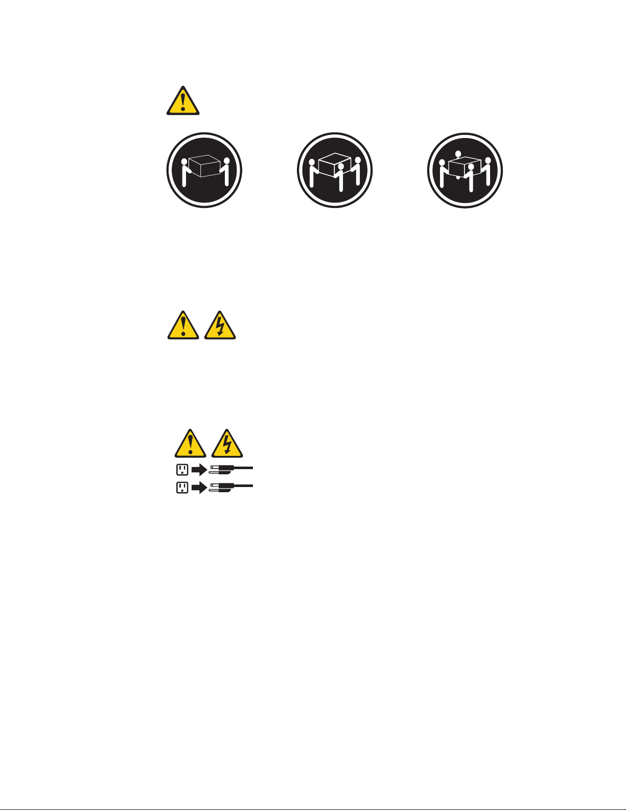
Statement 4:
≥ 18 kg (39.7 lb.) ≥ 32 kg (70.5 lb.) ≥ 55 kg (121.2 lb.)
CAUTION:
Use safe practices when lifting.
Statement 5:
CAUTION:
The power control button on the device and the power switch on the power
supply do not turn off the electrical current supplied to the device. The device
also might have more than one power cord. To remove all electrical current from
the device, ensure that all power cords are disconnected from the power source.
2
1
x Installation and User Guide
Page 13
Statement 8:
CAUTION:
Never remove the cover on a power supply or any part that has the following
label attached.
Hazardous voltage, current, and energy levels are present inside any component
that has this label attached. There are no serviceable parts inside these
components. If you suspect a problem with one of these parts, contact a service
technician.
Statement 9:
CAUTION:
To avoid personal injury, disconnect the hot-swap fan cables before removing
the fan from the device.
Statement 11:
CAUTION:
The following label indicates sharp edges, corners, or joints nearby.
Statement 12:
Safety xi
Page 14
CAUTION:
The following label indicates a hot surface nearby.
Statement 13:
DANGER
Overloading a branch circuit is potentially a fire hazard and a shock hazard
under certain conditions. To avoid these hazards, ensure that your system
electrical requirements do not exceed branch circuit protection requirements.
Refer to the information that is provided with your device for electrical
specifications.
Statement 15:
CAUTION:
Make sure that the rack is secured properly to avoid tipping when the server
unit is extended.
Statement 17:
CAUTION:
The following label indicates moving parts nearby.
Statement 26:
xii Installation and User Guide
Page 15
CAUTION:
Do not place any object on top of rack-mounted devices.
Statement 27:
CAUTION:
Hazardous moving parts are nearby.
Statement 28:
CAUTION:
The battery is a lithium ion battery. To avoid possible explosion, do not burn the
battery. Exchange it only with the Lenovo-approved part. Recycle or discard the
battery as instructed by local regulations.
Attention: This product is suitable for use on an IT power distribution system
whose maximum phase to phase voltage is 240 V under any distribution fault
condition.
Safety xiii
Page 16

xiv Installation and User Guide
Page 17
Chapter 1. Introduction
This Installation and User Guide is intended to be used with your Lenovo
ThinkServer™TS200v (Machine Types 0981, 0992, 1008, and 1010) server. This
document contains information about:
v Setting up and cabling the server
v Starting and configuring the server
v Installing options and replacing customer replaceable units (CRUs)
v Troubleshooting and diagnostics
The server comes with the ThinkServer EasyStartup DVD to help you configure the
hardware, install device drivers, and install the operating system.
The server comes with a limited warranty. For information about the terms of the
warranty and getting service and assistance, see the Warranty and Support
Information document on the ThinkServer Documentation DVD that comes with the
server. To obtain up-to-date information about the server and other Lenovo
products, go to: http://www.lenovo.com/thinkserver
Record information about the server in the following table. You will need this
information when you register the server with Lenovo.
Product name ThinkServer TS200v
Machine type 0981, 0992, 1008, and 1010
Model number _____________________________________________
Serial number _____________________________________________
®
© Copyright Lenovo 2010 1
Page 18
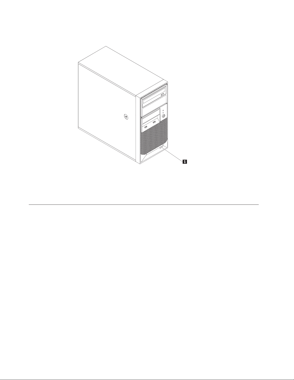
The model number and serial number are on a label on the front bezel, as shown
in the following illustration:
1 Model number and serial number
For a list of supported optional devices for the server, go to
http://www.lenovo.com/thinkserver and click the Options tab.
Notices and statements in this document
The caution and danger statements that appear in this document are also in the
multilingual Safety Information document, which is on the Lenovo ThinkServer
Documentation DVD. Each statement is numbered for reference to the
corresponding statement in the Safety Information document.
The following notices and statements are used in this document:
v Note: These notices provide important tips, guidance, or advice.
v Important: These notices provide information or advice that might help you
avoid inconvenient or problem situations.
v Attention: These notices indicate potential damage to programs, devices, or data.
An attention notice is placed just before the instruction or situation in which
damage could occur.
v Caution: These statements indicate situations that can be potentially hazardous
to you. A caution statement is placed just before the description of a potentially
hazardous procedure step or situation.
v Danger: These statements indicate situations that can be potentially lethal or
extremely hazardous to you. A danger statement is placed just before the
description of a potentially lethal or extremely hazardous procedure step or
situation.
2 Installation and User Guide
Page 19
Related documentation
The Lenovo ThinkServer Documentation DVD contains documentation for the server
in Portable Document Format (PDF). The Lenovo ThinkServer Documentation DVD
requires the Adobe
operating systems.
The following table describes the content and location of documentation that is
provided with your server.
Document Description Location
Read Me First This document directs you to the
Important Notices This document includes safety and legal
Hardware
Maintenance
Manual
Warranty and
Support
Information
Safety Information This document includes translations of all
®
Reader 5.0 (or later) or xpdf, which comes with Linux
Printed, provided in
ThinkServer Documentation DVD for
complete warranty and support
information.
notices that you are expected to read
before using the server.
This document provides diagnostic
information, parts listing, and
replacement procedures for all field
replaceable units (FRUs, parts that can
only be replaced by trained service
personnel) as well as all customer
replaceable units (CRUs).
This document includes the warranty
statement and information about how to
contact Lenovo Support.
of the safety statements used in the
ThinkServer documentation.
server packaging
Printed, provided in
server packaging
Lenovo Support Web site:
http://www.lenovo.com/
support
Available on the
ThinkServer Documentation
DVD
Available on the
ThinkServer Documentation
DVD
®
Chapter 1. Introduction 3
Page 20

4 Installation and User Guide
Page 21

Chapter 2. Server setup roadmap
The installation process varies depending on the configuration of the server when
it was delivered. In some cases, the server is fully configured and just needs to be
connected to power and the network and started. In other cases, the server needs
to have hardware features installed, requires hardware and firmware configuration,
and requires the operating system to be installed.
Table 1. Server setup roadmap
Task Where to find information
Unpack Chapter 3, “What is included with your server,” on page 7
Install hardware
features
Connect Ethernet cable
and power cords to
network and power
connectors
Review Unified
Extensible Firmware
Interface (UEFI)
settings and customize
as needed
Configure RAID “Configuring RAID” on page 52
Check for firmware
updates
Install operating
system and basic
drivers
Install any additional
drivers needed for
added features
Configure Ethernet
settings in operating
system
Install remote
management
applications
Install applications Refer to the documentation that accompanies the applications that
Chapter 5, “Installing or replacing customer replaceable units,” on
page 17
“Rear view” on page 12
“Using the Setup Utility program” on page 49
Go to http://www.lenovo.com/support and go to the Downloads
and Drivers section for this product.
“Using the ThinkServer EasyStartup program” on page 56
Refer to the instructions that came with the hardware option.
See the operating system help. This step is not required if the
operating system was installed using the ThinkServer EasyStartup
program.
“Installing ThinkServer EasyManage Agent” on page 58
you want to install.
© Copyright Lenovo 2010 5
Page 22

6 Installation and User Guide
Page 23
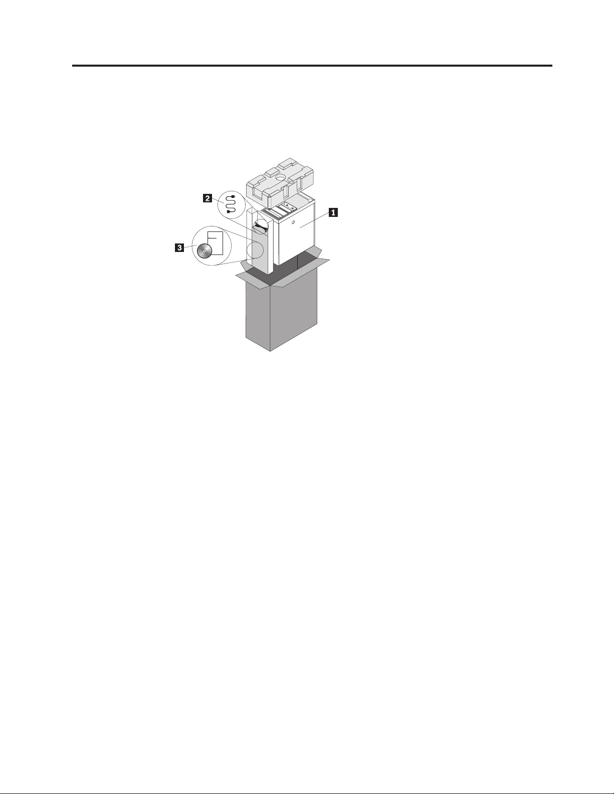
Chapter 3. What is included with your server
The TS200v server package includes the server, a power cord, the ThinkServer
Documentation DVD, and software media.
1 Server
2 Power cord
3 Documentation and software media
© Copyright Lenovo 2010 7
Page 24
Features and specifications
The following information is a summary of the features and specifications of the
server. Depending on the server model, some features might not be available, or
some specifications might not apply.
Table 2. Features and specifications
Microprocessor
Your server comes with one of the
following microprocessors (internal cache
size varies by model type):
®
v Intel
v Intel Core
v Intel Core i5 microprocessor
v Intel Pentium
Notes:
v Use the Setup Utility program to
v For a list of supported microprocessors,
Memory
v Supports up to four DDR3 ECC
Internal drives
v Serial Advanced Technology Attachment
v SATA optical drive
Video subsystem
v Integrated graphics for a Video Graphics
Connectivity
v 10/100/1000 Mbps integrated Ethernet
Power supply
v 280-watt auto-sensing power supply
Celeron®microprocessor
™
i3 microprocessor
®
microprocessor
determine the type and speed of the
microprocessor.
see http://www.lenovo.com/
thinkserver and click the Options tab.
UDIMMs (double data rate 3 error
correction code unbuffered dual inline
memory modules)
(SATA) hard disk drive
Array (VGA) connector and a
DisplayPort connector
controller
Expansion
v Two hard disk drive bays (one standard
and one optional)
v Two optical drive bays
v Two PCI card slots
v One PCI Express x1 card slot
v One PCI Express x16 card slot
System management features
v Ability to store power-on self-test
(POST) hardware test results
v Automatic power-on startup
v Intel Active Management Technology
(AMT)
v Intel Hyper-Threading technology (some
models)
v Intel Rapid Storage Technology (RST)
v Preboot Execution Environment (PXE)
v System Management (SM) UEFI and SM
software
v Wake on LAN
v Wake on Ring (in the Setup Utility
program, this feature is called Serial
Port Ring Detect for an external
modem)
Input/Output (I/O) features
v Eight Universal Serial Bus (USB)
connectors (two on the front panel and
six on the rear panel)
v One 9-pin serial port
v One Ethernet connector
v One DisplayPort connector
v One VGA monitor connector
v Three audio connectors on the rear
panel (audio line-in connector, audio
line-out connector, and microphone
connector)
Security features
v Computrace
v Enabling or disabling a device
v Enabling or disabling USB connectors
individually
v Hard disk drive password
v Power-On Password (POP) and
Administrator Password for UEFI access
v Startup sequence control
v Startup without keyboard or mouse
v Support for an integrated cable lock
(Kensington lock)
v Support for a padlock
v Trusted Platform Module (TPM)
Preinstalled operating system
Some models are preinstalled with one of
the following operating systems:
v Microsoft
Foundation
v Microsoft Windows Server 2008 R2
Standard
v Windows
Standard (Service Pack 2)
Operating system(s), supported
v Microsoft Windows Server 2008 R2
Enterprise
®
Windows Server®2008 R2
®
Small Business Server 2008
8 Installation and User Guide
Page 25
Table 2. Features and specifications (continued)
Dimensions
Width: 174.8 mm (6.88 inches)
Height: 377.3 mm (14.85 inches)
Depth: 406.7 mm (16.01 inches)
Weight
Maximum configuration: 11.2 kg (24.7
lbs)
Environment
Air temperature:
Operating: 10° to 35°C (50° to 95°F)
Non-operating: -40° to 60°C (-40° to
140°F) (with package)
Non-operating: -10° to 60°C (14° to
140°F) (without package)
Humidity:
Operating: 8% to 80%
(non-condensing)
Non-operating: 8% to 80%
(non-condensing)
Altitude:
Operating: 0 to 10 000 ft (0 to 3 048
m)
Non-operating: 0 to 35 000 ft (0 to
10 668 m)
Software
Lenovo provides software to help get your server up and running.
EasyStartup
The ThinkServer EasyStartup program simplifies the process of installing
supported Microsoft Windows operating systems and device drivers on your
server. The EasyStartup program is provided with your server on DVD. The DVD
is self starting (bootable). The User Guide for the EasyStartup program is on the
DVD and can be accessed directly from the program interface. For additional
information, see “Using the ThinkServer EasyStartup program” on page 56.
Electrical input
Input voltage low range:
Minimum: 100 V ac
Maximum: 127 V ac
Input frequency range: 50 to 60 Hz
Voltage-selection switch setting: 115 V
ac
Input voltage high range:
Minimum: 200 V ac
Maximum: 240 V ac
Input frequency range: 50 to 60 Hz
Voltage-selection switch setting: 230 V
ac
EasyManage
The ThinkServer EasyManage Agent enables other clients on the network to be
managed by the centralized console. The ThinkServer EasyManage Agent is
supported on 32-bit and 64-bit Windows, Red Hat, and SUSE operating systems.
Chapter 3. What is included with your server 9
Page 26

10 Installation and User Guide
Page 27
Chapter 4. Server controls and connectors
This chapter provides information about the server controls and connectors.
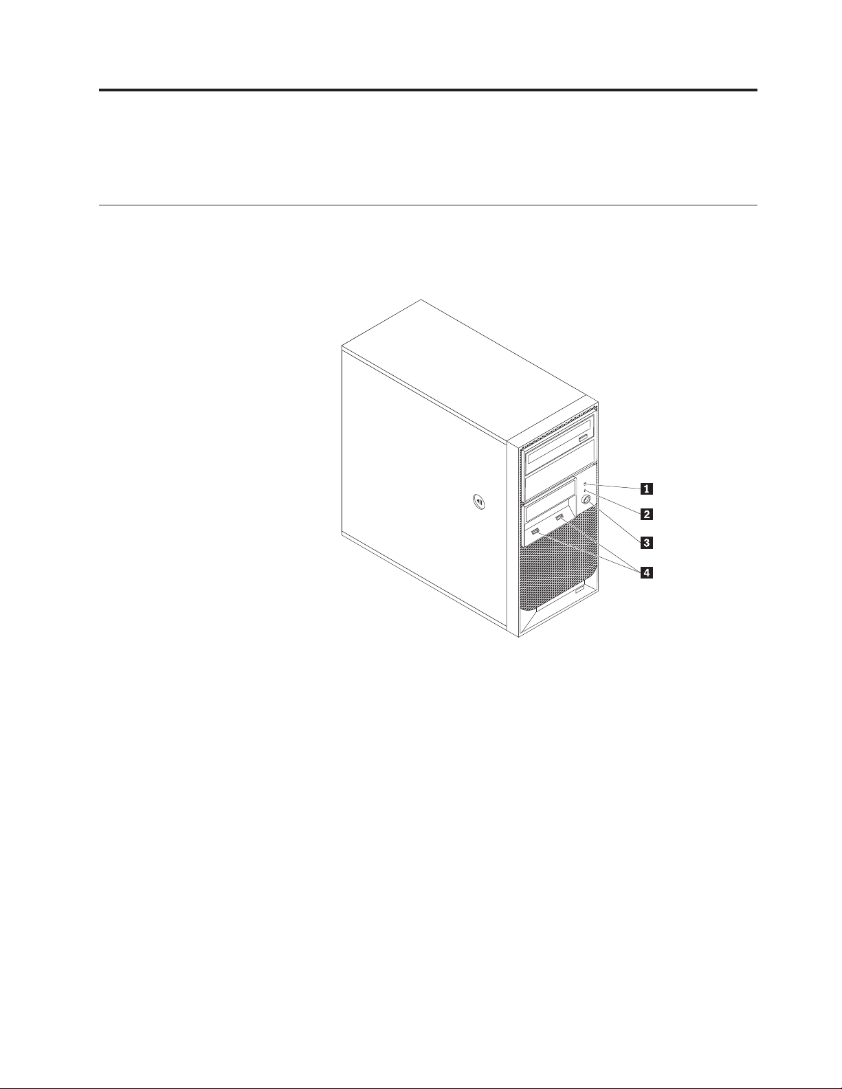
Front view
Figure 1 shows the locations of the controls and connectors on the front of your
server.
Figure 1. Front control and connector locations
1 Hard disk drive activity LED 3 Power switch
2 Power-on LED 4 USB connectors (2)
© Copyright Lenovo 2010 11
Page 28
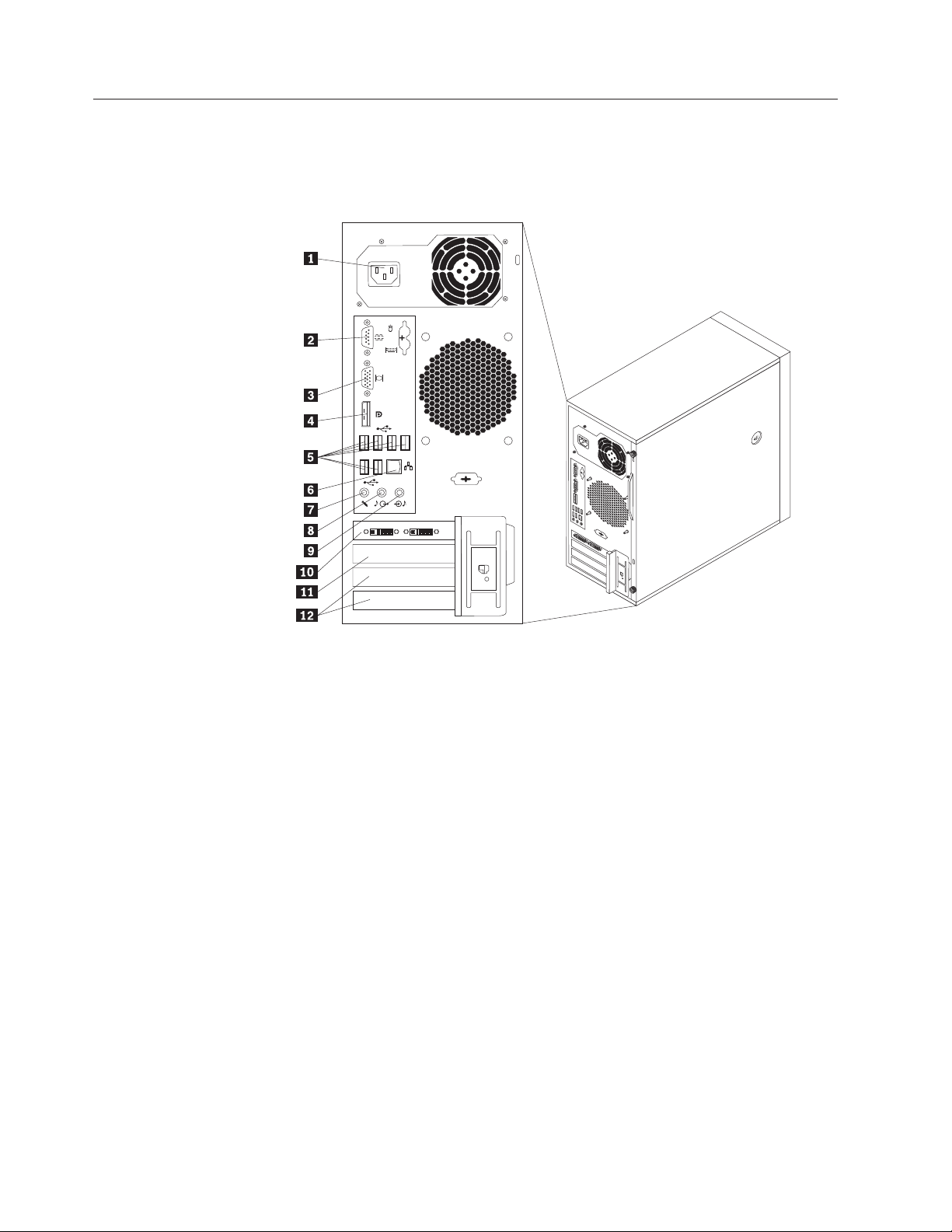
Rear view
Figure 2 shows the locations of the connectors on the rear of your server. Some
connectors on the rear of your server are color-coded to help you determine where
to connect the cables in your server.
Figure 2. Rear connector locations
1 Power cord connector 7 Microphone connector
2 Serial port 8 Audio line-out connector
3 VGA monitor connector 9 Audio line-in connector
4 DisplayPort connector 10 PCI Express x16 card slot
5 USB connectors (6) 11 PCI Express x1 card slot
6 Ethernet connector 12 PCI card slots (2)
12 Installation and User Guide
Page 29

Connector Description
Audio line-in connector Used to receive audio signals from an external audio device,
such as a stereo system. When you attach an external audio
device, a cable connects the audio line-out connector of the
device to the audio line-in connector of the server.
Audio line-out connector Used to send audio signals from the server to external devices,
such as powered stereo speakers (speakers with built-in
amplifiers), headphones, multimedia keyboards, or the audio
line-in connector on a stereo system or other external recording
device.
DisplayPort connector Used to attach a high-performance monitor, a direct-drive
monitor, or other devices that use a DisplayPort connector.
Ethernet connector Used to attach an Ethernet cable for a local area network (LAN).
Note: To operate the server within FCC Class B limits, use a
Category 5 Ethernet cable.
Microphone connector Used to attach a microphone to your server when you want to
record sound or if you use speech-recognition software.
Serial port Used to attach an external modem, a serial printer, or other
devices that use a 9-pin serial port.
USB connector Used to attach a device that requires a USB connector, such as a
USB keyboard, a USB mouse, a USB scanner, or a USB printer. If
you have more than eight USB devices, you can purchase a USB
hub, which you can use to connect additional USB devices.
VGA monitor connector Used to attach a VGA monitor or other devices that use a VGA
monitor connector.
Chapter 4. Server controls and connectors 13
Page 30

System-board internal connectors
Figure 3 shows the locations of the parts and connectors on the system board.
Figure 3. System board connector locations
1 4-pin power connector 11 eSATA connector
2 Microprocessor 12 Power fan connector
3 Microprocessor fan connector 13 Front panel connector
4 DIMM 2 14 Clear CMOS (Complementary Metal Oxide
Semiconductor) /Recovery jumper
5 DIMM 1 15 Front USB connectors (2)
6 DIMM 4 16 PCI card slots (2)
7 DIMM 3 17 PCI Express x1 card slot
8 Thermal sensor connector 18 PCI Express x16 card slot
9 24-pin power connector 19 System fan connector
10 SATA connectors (3) 20 Battery
14 Installation and User Guide
Page 31

Internal components
Figure 4 shows the locations of the various components in your server. To remove
the server cover and access to the inside of the server, see “Removing the server
cover” on page 18.
Figure 4. Component locations
1 Heat sink and fan assembly 4 PCI card
2 Memory module 5 Rear fan assembly
3 Optical drive 6 Power supply assembly
Chapter 4. Server controls and connectors 15
Page 32

Internal drives
Internal drives are devices that your server uses to read and store data. You can
add drives to your server to increase storage capacity and enable your server to
read other types of media. Internal drives are installed in bays. In this manual, the
bays are referred to as bay 1, bay 2, and so on.
Figure 5 shows the locations of the drive bays.
Figure 5. Drive bay locations
The following list describes the type and size of the drive that you can install in
each bay:
1 Bay 1 - Maximum height: 43.0 mm (1.7 inches) Optical drive
2 Bay 2 - Maximum height: 43.0 mm (1.7 inches) Optical drive
3 Bay 3 - Maximum height: 25.8 mm (1.0 inch) 3.5-inch secondary SATA hard disk
drive
4 Bay 4 - Maximum height: 25.8 mm (1.0 inch) 3.5-inch primary SATA hard disk drive
16 Installation and User Guide
Page 33

Chapter 5. Installing or replacing customer replaceable units
This chapter provides instructions on how to install or replace customer
replaceable units for your server.
This chapter contains the following sections:
v “Handling static-sensitive devices”
v “Installing or replacing hardware”
v “Installing security features” on page 46
Handling static-sensitive devices
Do not open the static-protective package containing the new part until the
defective part has been removed from the server and you are ready to install the
new part. Static electricity, although harmless to you, can seriously damage server
components and parts.
When you handle parts and other server components, take these precautions to
avoid static-electricity damage:
v Limit your movement. Movement can cause static electricity to build up around
you.
v Always handle parts and other server components carefully. Handle PCI cards,
memory modules, system boards, and microprocessors by the edges. Never
touch any exposed circuitry.
v Prevent others from touching the parts and other server components.
v Before you replace a new part, touch the static-protective package containing the
part to a metal expansion-slot cover or other unpainted metal surface on the
server for at least two seconds. This reduces static electricity in the package and
your body.
v When possible, remove the new part from the static-protective packaging, and
install it directly in the server without setting the part down. When this is not
possible, place the static-protective package that the part came in on a smooth,
level surface and place the part on it.
v Do not place the part on the server cover or other metal surface.
Installing or replacing hardware
This section provides instructions on how to install or replace hardware for your
server. You can expand the capabilities of your server and maintain your server by
installing or replacing hardware.
Attention
Do not open your server or attempt any repair before reading and
understanding the “Safety” on page v and the Safety Information book. To
obtain a copy of the Safety Information book, go to:
http://www.lenovo.com/support
Notes:
1. Use only server parts provided by Lenovo.
© Copyright Lenovo 2010 17
Page 34

2. When installing or replacing an option, use the appropriate instructions in this
section along with the instructions that come with the option.
Installing external options
You can connect external options to your server, such as external speakers, a
printer, or a scanner. For some external options, you must install additional
software in addition to making the physical connection. When installing an
external option, see “Front view” on page 11 and “Rear view” on page 12 to
identify the required connector. Then, use the instructions that come with the
option to help you make the connection and install any software or device drivers
that are required for the option.
Removing the server cover
Attention
Do not open your server or attempt any repair before reading and
understanding the “Safety” on page v and the Safety Information book. To
obtain a copy of the Safety Information book, go to:
http://www.lenovo.com/support
This section provides instructions on how to remove the server cover.
CAUTION:
Turn off the server and wait three to five minutes to let the server cool before
removing the server cover.
To remove the server cover, do the following:
1. Remove any media from the drives and turn off all attached devices and the
server.
2. Disconnect all power cords from electrical outlets.
3. Disconnect the power cords, Input/Output (I/O) cables, and any other cables
that are connected to the server. See “Front view” on page 11 and “Rear view”
on page 12.
4. Remove any locking device that secures the server cover, such as a padlock or
an integrated cable lock. See “Integrated cable lock” on page 46 and “Padlock”
on page 47.
5. Remove any thumbscrews that secure the server cover.
18 Installation and User Guide
Page 35

6. Press the cover-release button on the side of the server and slide the cover to
the rear of the server to remove the cover.
Figure 6. Removing the server cover
Removing and reinstalling the front bezel
Attention
Do not open your server or attempt any repair before reading and
understanding the “Safety” on page v and the Safety Information book. To
obtain a copy of the Safety Information book, go to:
http://www.lenovo.com/support
This section provides instructions on how to remove and reinstall the front bezel.
To remove and reinstall the front bezel, do the following:
1. Remove all media from the drives and turn off all attached devices and the
server. Then, disconnect all power cords from electrical outlets and disconnect
all cables that are connected to the server.
2. Remove the server cover. See “Removing the server cover” on page 18.
Chapter 5. Installing or replacing customer replaceable units 19
Page 36

3. Remove the front bezel by releasing the three plastic tabs on the left side and
pivoting the front bezel outward.
Figure 7. Removing the front bezel
4. To reinstall the front bezel, align the three plastic tabs on the right side of the
front bezel with the corresponding holes in the chassis, then pivot the front
bezel inward until it snaps into position on the left side.
What to do next:
v To work with another piece of hardware, go to the appropriate section.
v To complete the installation or replacement, go to “Completing the parts
replacement” on page 44.
Installing or replacing a PCI card
Attention
Do not open your server or attempt any repair before reading and
understanding the “Safety” on page v and the Safety Information book. To
obtain a copy of the Safety Information book, go to:
http://www.lenovo.com/support
This section provides instructions on how to install or replace a PCI card.
Your server has two standard PCI card slots, one PCI Express x1 card slot, and one
PCI Express x16 card slot.
20 Installation and User Guide
Page 37

To install or replace a PCI card, do the following:
1. Remove all media from the drives and turn off all attached devices and the
server. Then, disconnect all power cords from electrical outlets and disconnect
all cables that are connected to the server.
2. Remove the server cover. See “Removing the server cover” on page 18.
3. At the rear of the server, press the release button 1 to open the PCI card latch
2.
Figure 8. Opening the PCI card latch
Chapter 5. Installing or replacing customer replaceable units 21
Page 38

4. If you are installing a PCI card, remove the appropriate metal slot cover. If you
are replacing an old PCI card, grasp the old card that is currently installed and
gently pull it out of the slot.
Figure 9. Removing a PCI card
Note: The PCI card fits tightly into the card slot. If necessary, alternate moving
each side of the PCI card a small amount until it is removed from the card slot.
5. Remove the new PCI card from its static-protective package.
6. Install the new PCI card into the appropriate slot on the system board. See
“System-board internal connectors” on page 14.
Note: If you are installing a PCI Express x16 card, make sure the memory slot
retaining clips are closed before you install the PCI Express x16 card.
22 Installation and User Guide
Page 39

7. Pivot the PCI card latch to the closed position to secure the PCI card.
Figure 10. Installing a PCI card
What to do next:
v To work with another piece of hardware, go to the appropriate section.
v To complete the installation or replacement, go to “Completing the parts
replacement” on page 44.
Installing or replacing a memory module
Attention
Do not open your server or attempt any repair before reading and
understanding the “Safety” on page v and the Safety Information book. To
obtain a copy of the Safety Information book, go to:
http://www.lenovo.com/support
This section provides instructions on how to install or replace a memory module.
Your server has four slots for installing or replacing memory modules. When
installing or replacing a memory module, use the following guidelines:
v Use DDR3 ECC UDIMMs for your server.
v Use 1 GB, 2 GB, or 4 GB memory modules in any combination up to a
maximum of 16 GB system memory.
v Install memory modules in the sequence of DIMM 1, DIMM 2, DIMM 3, and
DIMM 4. See “System-board internal connectors” on page 14.
Chapter 5. Installing or replacing customer replaceable units 23
Page 40

To install or replace a memory module, do the following:
1. Remove all media from the drives and turn off all attached devices and the
server. Then, disconnect all power cords from electrical outlets and disconnect
all cables that are connected to the server.
2. Remove the server cover. See “Removing the server cover” on page 18.
3. Lay the server on its side for easier access to the system board.
4. Locate the memory slots. See “System-board internal connectors” on page 14.
5. Remove any parts that might prevent your access to the memory slots.
Note: Depending on your server model, you might need to remove the PCI
Express x16 card for easier access to the memory slots. See “Installing or
replacing a PCI card” on page 20.
6. If you are installing a new memory module, open the retaining clips of the
memory slot into which you want to install the new memory module.
Figure 11. Opening the retaining clips
If you are replacing an old memory module, open the retaining clips and
gently pull the memory module out of the memory slot.
Figure 12. Removing a memory module
24 Installation and User Guide
Page 41

7. Position the new memory module over the memory slot. Make sure that the
notch 1 on the memory module aligns correctly with the key 2 in the
memory slot. Press the memory module straight down into the memory slot
until the retaining clips close.
Figure 13. Installing a memory module
8. Reinstall all parts that have been removed.
What to do next:
v To work with another piece of hardware, go to the appropriate section.
v To complete the installation or replacement, go to “Completing the parts
replacement” on page 44.
Installing or replacing the optical drive
Attention
Do not open your server or attempt any repair before reading and
understanding the “Safety” on page v and the Safety Information book. To
obtain a copy of the Safety Information book, go to:
http://www.lenovo.com/support
This section provides instructions on how to install or replace the optical drive.
To install or replace an optical drive, do the following:
1. Remove all media from the drives and turn off all attached devices and the
server. Then, disconnect all power cords from electrical outlets and disconnect
all cables that are connected to the server.
2. Remove the server cover. See “Removing the server cover” on page 18.
3. Remove the front bezel. See “Removing and reinstalling the front bezel” on
page 19.
4. Depending on whether you are installing or replacing an optical drive, do one
of the following:
v If you are installing a secondary optical drive, remove the plastic panel in the
front bezel for the drive bay you want to use. If there is a metal static shield
installed in the drive bay, remove the metal static shield.
Chapter 5. Installing or replacing customer replaceable units 25
Page 42

v If you are replacing an optical drive, disconnect the signal cable and the
power cable from the rear of the optical drive, press the blue release button
1, and then slide the optical drive out of the optical drive bay.
Figure 14. Removing the optical drive
5. Install the optical drive retainer on the side of the new optical drive.
Figure 15. Installing the optical drive retainer
26 Installation and User Guide
Page 43

6. Slide the new optical drive into the optical drive bay from the front of the
server until the optical drive snaps into position.
Figure 16. Installing the optical drive
7. Reinstall the front bezel. See “Removing and reinstalling the front bezel” on
page 19.
8. Continue at “Connecting a SATA drive.”
What to do next:
v To work with another piece of hardware, go to the appropriate section.
v To complete the installation or replacement, go to “Completing the parts
replacement” on page 44.
Connecting a SATA drive
You can connect a SATA optical drive or a SATA hard disk drive to an available
SATA connector on the system board.
To connect a SATA drive, do the following:
1. Connect one end of the signal cable to the SATA drive and the other end to an
available SATA connector on the system board. See “System-board internal
connectors” on page 14.
Chapter 5. Installing or replacing customer replaceable units 27
Page 44

2. Locate an available five-wire power connector and connect it to the SATA drive.
Figure 17. Connecting a SATA optical drive
Figure 18. Connecting a SATA hard disk drive
Installing or replacing the secondary hard disk drive
Attention
Do not open your server or attempt any repair before reading and
understanding the “Safety” on page v and the Safety Information book. To
obtain a copy of the Safety Information book, go to:
http://www.lenovo.com/support
This section provides instructions on how to install or replace the secondary hard
disk drive.
Installing a secondary hard disk drive
To install a secondary hard disk drive, do the following:
1. Remove all media from the drives and turn off all attached devices and the
server. Then, disconnect all power cords from electrical outlets and disconnect
all cables that are connected to the server.
2. Remove the server cover. See “Removing the server cover” on page 18.
3. Locate the secondary hard disk drive bay. See “Internal drives” on page 16.
28 Installation and User Guide
Page 45

4. Press the release button 1 to release the secondary hard disk drive cage and
then lift the cage out of the chassis.
Figure 19. Removing the secondary hard disk drive cage
5. Pull on the handle to release and remove the blue hard disk drive bracket
from the hard disk drive cage.
6. To install the new hard disk drive into the blue bracket, flex the sides of the
bracket properly and align pin 1, pin 2, pin 3, and pin 4 on the
bracket with the corresponding holes in the hard disk drive. Do not touch the
circuit board 5 on the bottom of the hard disk drive.
Note: If you are installing a 2.5-inch hard disk drive, install the hard disk
drive into a 2.5-inch to 3.5-inch hard disk drive tray first and then install the
tray into the blue bracket.
Figure 20. Installing the hard disk drive into the bracket
Chapter 5. Installing or replacing customer replaceable units 29
Page 46

7. Slide the new hard disk drive with the blue bracket into the secondary hard
disk drive cage until it snaps into position.
8. Slide the hard disk drive cage with the new hard disk drive into the chassis
until it is directly underneath the metal tab 1.
Figure 21. Installing the secondary hard disk drive
30 Installation and User Guide
Page 47

9. Press the hard disk drive cage downward until it snaps into position. Make
sure that the hard disk drive cage is secured in the chassis.
Figure 22. Installing the secondary hard disk drive
10. Continue at “Connecting a SATA drive” on page 27.
Replacing the secondary hard disk drive
Note: Depending on the model type, your server might have a secondary hard
disk drive installed.
To replace the secondary hard disk drive, do the following:
1. Remove all media from the drives and turn off all attached devices and the
server. Then, disconnect all power cords from electrical outlets and disconnect
all cables that are connected to the server.
2. Remove the server cover. See “Removing the server cover” on page 18.
3. Locate the secondary hard disk drive. See “Internal drives” on page 16.
4. Disconnect the signal cable and the power cable from the hard disk drive.
Chapter 5. Installing or replacing customer replaceable units 31
Page 48

5. Press the release button 1 to release the hard disk drive cage and then lift the
hard disk drive cage out of the chassis.
Figure 23. Removing the secondary hard disk drive
6. Pull on the blue handle to release and remove the hard disk drive from the
hard disk drive cage.
7. Flex the sides of the blue bracket to remove the hard disk drive from the
bracket.
8. Continue at “Installing a secondary hard disk drive” on page 28.
What to do next:
v To work with another piece of hardware, go to the appropriate section.
v To complete the replacement, go to “Completing the parts replacement” on
page 44.
Replacing the power supply assembly
Attention
Do not open your server or attempt any repair before reading and
understanding the “Safety” on page v and the Safety Information book. To
obtain a copy of the Safety Information book, go to:
http://www.lenovo.com/support
This section provides instructions on how to replace the power supply assembly.
To replace the power supply assembly, do the following:
32 Installation and User Guide
Page 49

1. Remove all media from the drives and turn off all attached devices and the
server. Then, disconnect all power cords from electrical outlets and disconnect
all cables that are connected to the server.
2. Remove the server cover. See “Removing the server cover” on page 18.
3. Disconnect the power supply assembly cables from the system board and all
drives. See “System-board internal connectors” on page 14.
4. Lay the server on its side and remove the four screws at the rear of the chassis
that secure the power supply assembly.
Figure 24. Removing the screws for the power supply assembly
5. Slide the power supply assembly to the front of the server and then lift it out
of the chassis.
6. Ensure that the new power supply assembly is the correct replacement.
7. Install the new power supply assembly into the chassis so that the screw holes
in the power supply assembly are aligned with the corresponding holes in the
chassis.
8. Install and tighten the four screws to secure the new power supply assembly.
Note: Use only screws provided by Lenovo.
9. Connect the new power supply assembly cables to the system board and each
of the drives. See “System-board internal connectors” on page 14.
What to do next:
v To work with another piece of hardware, go to the appropriate section.
v To complete the replacement, go to “Completing the parts replacement” on
page 44.
Chapter 5. Installing or replacing customer replaceable units 33
Page 50

Replacing the heat sink and fan assembly
Attention
Do not open your server or attempt any repair before reading and
understanding the “Safety” on page v and the Safety Information book. To
obtain a copy of the Safety Information book, go to:
http://www.lenovo.com/support
This section provides instructions on how to replace the heat sink and fan
assembly.
CAUTION:
The heat sink and fan assembly might be very hot. Turn off the server and wait
three to five minutes to let the server cool before removing the server cover.
To replace the heat sink and fan assembly, do the following:
1. Remove all media from the drives and turn off all attached devices and the
server. Then, disconnect all power cords from electrical outlets and disconnect
all cables that are connected to the server.
2. Remove the server cover. See “Removing the server cover” on page 18.
3. Lay the server on its side for easier access to the system board.
4. Locate the heat sink and fan assembly. See “System-board internal connectors”
on page 14.
5. Disconnect the heat sink and fan assembly cable from the microprocessor fan
connector on the system board. See “System-board internal connectors” on
page 14.
34 Installation and User Guide
Page 51

6. Follow this sequence to remove the four screws that secure the heat sink and
fan assembly to the system board:
a. Partially remove screw 1, then fully remove screw 2, and then fully
remove screw 1.
b. Partially remove screw 3, then fully remove screw 4, and then fully
remove screw 3.
Note: Carefully remove the four screws from the system board to avoid any
possible damage to the system board. The four screws cannot be removed
from the heat sink and fan assembly.
Figure 25. Removing the heat sink and fan assembly
7. Lift the failing heat sink and fan assembly off the system board.
Notes:
a. You might have to gently twist the heat sink and fan assembly to free it
from the microprocessor.
b. When handling the heat sink and fan assembly, do not touch the thermal
grease on the bottom of the heat sink and fan assembly.
8. Position the new heat sink and fan assembly on the system board so that the
four screws are aligned with the corresponding holes in the system board.
Make sure that the heat sink and fan assembly cable can be easily connected
to the microprocessor fan connector on the system board.
9. Follow this sequence to install the four screws to secure the heat sink and fan
assembly, as shown in Figure 25.
a. Partially tighten screw 1, then fully tighten screw 2, and then fully
tighten screw 1.
b. Partially tighten screw 3, then fully tighten screw 4, and then fully
tighten screw 3.
Chapter 5. Installing or replacing customer replaceable units 35
Page 52

10. Connect the heat sink and fan assembly cable to the microprocessor fan
connector on the system board. See “System-board internal connectors” on
page 14.
What to do next:
v To work with another piece of hardware, go to the appropriate section.
v To complete the replacement, go to “Completing the parts replacement” on
page 44.
Replacing the primary hard disk drive
Attention
Do not open your server or attempt any repair before reading and
understanding the “Safety” on page v and the Safety Information book. To
obtain a copy of the Safety Information book, go to:
http://www.lenovo.com/support
This section provides instructions on how to replace the primary hard disk drive.
To replace the primary hard disk drive, do the following:
1. Remove all media from the drives and turn off all attached devices and the
server. Then, disconnect all power cords from electrical outlets and disconnect
all cables that are connected to the server.
2. Remove the server cover. See “Removing the server cover” on page 18.
3. Locate the primary hard disk drive. See “Internal drives” on page 16.
4. Disconnect the signal cable and the power cable from the rear of the hard disk
drive.
36 Installation and User Guide
Page 53

5. Press the blue release tab 1 downward, slide the hard disk drive cage 2 to
the rear of the server, and then pivot it outward to completely remove the
drive cage from the chassis. Then, pull on the blue handle 3 to release and
remove the hard disk drive from the drive cage.
Figure 26. Removing the primary hard disk drive
6. Flex the sides of the blue bracket to remove the hard disk drive from the
bracket.
Chapter 5. Installing or replacing customer replaceable units 37
Page 54

7. To install a new hard disk drive into the blue bracket, flex the sides of the
bracket and align pin 1, pin 2, pin 3, and pin 4 on the bracket with
the corresponding holes in the hard disk drive. Do not touch the circuit board
5 on the bottom of the hard disk drive.
Note: If you are installing a 2.5-inch hard disk drive, install the hard disk
drive into a 2.5-inch to 3.5-inch hard disk drive tray first and then install the
tray into the blue bracket.
Figure 27. Installing the hard disk drive into the bracket
8. Slide the new hard disk drive with the blue bracket into the drive cage until it
snaps into position.
38 Installation and User Guide
Page 55

9. Align the hard disk drive cage pivot pin with the slot 1 in the upper drive
cage, as shown in Figure 28. Then, slide the hard disk drive cage into the
chassis.
10. Press down on the metal latch 2 and pivot the hard disk drive cage into
place. Then, slide the drive cage to the front of the server until it snaps into
position.
Note: There are two arrows, one on the upper drive cage and one on the hard
disk drive cage. The arrows are aligned when the hard disk drive is in the
proper position.
Figure 28. Installing the primary hard disk drive
Chapter 5. Installing or replacing customer replaceable units 39
Page 56

11. Connect the signal cable and the power cable to the new hard disk drive. See
“Connecting a SATA drive” on page 27.
What to do next:
v To work with another piece of hardware, go to the appropriate section.
v To complete the replacement, go to “Completing the parts replacement” on
page 44.
Replacing the front fan assembly
Attention
Do not open your server or attempt any repair before reading and
understanding the “Safety” on page v and the Safety Information book. To
obtain a copy of the Safety Information book, go to:
http://www.lenovo.com/support
Depending on the model type, your server might have a front fan assembly
installed. This section provides instructions on how to replace the front fan
assembly.
To replace the front fan assembly, do the following:
1. Remove all media from the drives and turn off all attached devices and the
server. Then, disconnect all power cords from electrical outlets and disconnect
all cables that are connected to the server.
2. Remove the server cover. See “Removing the server cover” on page 18.
3. Remove the front bezel. See “Removing and reinstalling the front bezel” on
page 19.
4. Disconnect the front fan assembly cable from the power fan connector on the
system board. See “System-board internal connectors” on page 14.
Note: If your server has a secondary hard disk drive installed, remove the
secondary hard disk drive to get easier access to the power fan connector on
the system board. See “Installing or replacing the secondary hard disk drive”
on page 28.
40 Installation and User Guide
Page 57

5. Release the two tabs 1 that attach the front fan assembly to the chassis as
shown and then completely remove the front fan assembly from the chassis.
Figure 29. Removing the front fan assembly
Chapter 5. Installing or replacing customer replaceable units 41
Page 58

6. Insert the two tabs 2 of the new front fan assembly into the corresponding
holes in the chassis, and press the other two tabs 1 through the holes until
the front fan assembly is secured in place.
Figure 30. Installing the front fan assembly
7. Connect the new front fan assembly cable to the power fan connector on the
system board. See “System-board internal connectors” on page 14.
8. Reinstall the secondary hard disk drive if removed. See “Installing or replacing
the secondary hard disk drive” on page 28.
What to do next:
v To work with another piece of hardware, go to the appropriate section.
v To complete the replacement, go to “Completing the parts replacement” on
page 44.
42 Installation and User Guide
Page 59

Replacing the rear fan assembly
Attention
Do not open your server or attempt any repair before reading and
understanding the “Safety” on page v and the Safety Information book. To
obtain a copy of the Safety Information book, go to:
http://www.lenovo.com/support
This section provides instructions on how to replace the rear fan assembly.
To replace the rear fan assembly, do the following:
1. Remove all media from the drives and turn off all attached devices and the
server. Then, disconnect all power cords from electrical outlets and disconnect
all cables that are connected to the server.
2. Remove the server cover. See “Removing the server cover” on page 18.
3. Locate the rear fan assembly. See “Internal components” on page 15.
4. Disconnect the rear fan assembly cable from the system fan connector on the
system board. See “System-board internal connectors” on page 14.
5. The rear fan assembly is attached to the chassis by four rubber mounts.
Remove the rear fan assembly by cutting the rubber mounts and gently pulling
the rear fan assembly out of the chassis.
Figure 31. Removing the rear fan assembly
6. Install the new rear fan assembly by aligning the new rubber mounts with the
corresponding holes in the chassis and push the rubber mounts through the
holes.
Note: The new rear fan assembly will have four new rubber mounts attached.
Chapter 5. Installing or replacing customer replaceable units 43
Page 60

7. Carefully pull on the tips of the rubber mounts until the new rear fan assembly
is secured in place.
Figure 32. Installing the rear fan assembly
8. Connect the new rear fan assembly cable to the system fan connector on the
system board. See “System-board internal connectors” on page 14.
What to do next:
v To work with another piece of hardware, go to the appropriate section.
v To complete the replacement, go to “Completing the parts replacement.”
Completing the parts replacement
After completing the installation or replacement for all parts, you need to reinstall
the server cover and reconnect cables.
To reinstall the server cover and reconnect cables to your server, do the following:
1. Make sure that all components have been reassembled correctly and that no
tools or loose screws are left inside your server. See “Internal components” on
page 15 for the locations of various components in your server.
2. If you have removed the front bezel, reinstall it. See “Removing and reinstalling
the front bezel” on page 19.
3. Make sure that the cables are routed correctly before reinstalling the server
cover. Keep cables clear of the hinges and sides of the server chassis to avoid
44 Installation and User Guide
Page 61

interference with reinstalling the server cover.
4. Position the server cover on the chassis so that the rail guides on the bottom of
the server cover engage the rails on the chassis. Then, slide the cover to the
front of the server until it snaps into position.
Figure 33. Reinstalling the server cover
5. Install the screws to secure the server cover.
6. Lock the server cover if you have a server cover lock. See “Integrated cable
lock” on page 46 or “Padlock” on page 47.
7. Reconnect the external cables and power cords to the server. See “Front view”
on page 11 and “Rear view” on page 12.
8. Depending on the parts you installed or replaced, you might need to confirm
the updated information in the Setup Utility program. Refer to Chapter 6,
“Configuring the server,” on page 49.
Note: In most areas of the world, Lenovo requires the return of the defective
Customer Replaceable Unit (CRU). Information about this will come with the CRU
or will come a few days after the CRU arrives.
Updating the server configuration
When you start the server for the first time after you install or remove an internal
option or external device, you might receive a message that the configuration has
changed. The Setup Utility program starts automatically so that you can save the
new configuration settings.
Some options have device drivers that you must install. For information about
installing device drivers, see the documentation that comes with each option.
Chapter 5. Installing or replacing customer replaceable units 45
Page 62

You can obtain device drivers for operating systems that are not preinstalled at
http://www.lenovo.com/support. Installation instructions are provided in readme
files with the device-driver files.
Installing security features
There are several security options available to help you prevent hardware theft and
unauthorized access to your server. In addition to physical locks, you can also
prevent unauthorized use of your server by a software lock that locks the keyboard
until a correct password is typed in.
Note: Make sure that any security cables you installed do not interfere with other
server cables.
Integrated cable lock
An integrated cable lock, sometimes referred to as the Kensington lock, can be
used to secure your server to a desk, table, or other non-permanent fixture. The
cable lock attaches to the integrated cable lock slot at the rear of your server and is
operated with a key. The cable lock also locks the buttons used to remove the
server cover. This is the same type of lock used with many notebook computers.
You can order an integrated cable lock directly from Lenovo by searching for
Kensington at:
http://www.lenovo.com/support
Figure 34. Installing an integrated cable lock
46 Installation and User Guide
Page 63

Padlock
Your server is equipped with a padlock loop so that the cover cannot be removed
when a padlock is installed.
Figure 35. Installing a padlock
Password protection
To deter unauthorized use of your server, you can use the Setup Utility program to
set a password. When you turn on your server, you are prompted to type the
password. The server cannot be used until a valid password is typed in. Refer to
Chapter 6, “Configuring the server,” on page 49 for more information.
Erasing lost or forgotten passwords (clearing CMOS)
This section provides instructions on how to erase lost or forgotten passwords,
such as a user password.
To erase a lost or forgotten password, do the following:
1. Remove all media from the drives and turn off all attached devices and the
server. Then, disconnect all power cords from electrical outlets and disconnect
all cables that are connected to the server.
2. Remove the server cover. See “Removing the server cover” on page 18.
3. Locate the Clear CMOS /Recovery jumper on the system board. See
“System-board internal connectors” on page 14.
4. Remove all parts and disconnect all cables that might prevent your access to
the Clear CMOS /Recovery jumper.
Note: If your server has a secondary hard disk drive installed, remove the
secondary hard disk drive to access the Clear CMOS /Recovery jumper. See
“Replacing the secondary hard disk drive” on page 31.
Chapter 5. Installing or replacing customer replaceable units 47
Page 64

5. Move the jumper from the standard position (pin 1 and pin 2) to the
maintenance position (pin 2 and pin 3).
6. Reinstall all parts and reconnect all cables that have been removed.
7. Reinstall the server cover and reconnect the server power cord. See
“Completing the parts replacement” on page 44.
8. Turn on the server and leave it on for approximately 10 seconds. Then, turn
off the server by holding the power switch for approximately five seconds.
9. Repeat step 1 through step 4.
10. Move the Clear CMOS /Recovery jumper back to the standard position (pin 1
and pin 2).
11. Reinstall all parts and reconnect all cables that have been removed.
12. Reinstall the server cover and connect the power cords. See “Completing the
parts replacement” on page 44.
48 Installation and User Guide
Page 65

Chapter 6. Configuring the server
This chapter provides instructions on how to configure your server.
This chapter provides information on the following topics:
v “Using the Setup Utility program”
v “Configuring RAID” on page 52
v “Updating system programs” on page 54
v “Using the ThinkServer EasyStartup program” on page 56
v “Installing ThinkServer EasyManage Agent” on page 58
Using the Setup Utility program
The Setup Utility program is used to view and change the configuration settings of
your server, regardless of which operating system you are using. However, the
operating system settings might override any similar settings in the Setup Utility
program.
This section provides information on the following topics to help you use the
Setup Utility program:
v “Starting the Setup Utility program”
v “Viewing and changing settings”
v “Using passwords” on page 50
v “Enabling or disabling a device” on page 51
v “Selecting a startup device” on page 51
v “Advanced settings” on page 52
v “Exiting from the Setup Utility program” on page 52
Starting the Setup Utility program
To start the Setup Utility program, do the following:
1. Make sure your server is turned off.
2. Repeatedly press and release the F1 key when turning on the server. When you
hear multiple beeps or see a logo screen, release the F1 key.
Note: If a Power-On Password or an Administrator Password has been set, the
Setup Utility program menu will not be displayed until you type the correct
password. For more information, see “Using passwords” on page 50.
The Setup Utility program might start automatically when POST detects that
hardware has been removed or new hardware has been installed in your server.
Viewing and changing settings
The Setup Utility program menu lists various items about the system
configuration. To view or change settings, start the Setup Utility program. See
“Starting the Setup Utility program.” Then, follow the instructions on the screen.
When working with the Setup Utility program menu, you must use the keyboard.
The keys used to perform various tasks are displayed at the bottom of each screen.
© Copyright Lenovo 2010 49
Page 66

Using passwords
By using the Setup Utility program, you can set passwords to prevent
unauthorized access to your server and data. The following types of passwords are
available:
v Power-On Password
v Administrator Password
v Hard Disk Password
You do not have to set a password to use your server. However, using passwords
improves computing security. If you decide to set a password, read the following
sections.
Password considerations
A password can be any combination of up to 64 alphabetic and numeric characters.
For security reasons, it is recommended to use a strong password that cannot be
easily compromised. To set a strong password, use the following guidelines:
v Have at least eight characters in length
v Contain at least one alphabetic character and one numeric character
v Setup Utility program and hard disk drive passwords are not case sensitive
v Not be your name or your user name
v Not be a common word or a common name
v Be significantly different from your previous passwords
Power-On Password
When a Power-On Password is set, you are prompted to type a valid password
each time the server is turned on. The server cannot be used until the valid
password is typed in.
Administrator Password
Setting an Administrator Password deters unauthorized users from changing
configuration settings. If you are responsible for maintaining the configuration
settings of several servers, you might want to set an Administrator Password.
When an Administrator Password is set, you are prompted to type a valid
password each time you try to access the Setup Utility program. The Setup Utility
program cannot be accessed until a valid password is typed in.
If both the Power-On Password and Administrator Password are set, you can type
either password. However, you must use your Administrator Password to change
any configuration settings.
Hard Disk Password
Setting a Hard Disk Password prevents unauthorized access to the data on the
hard disk drive. When a Hard Disk Password is set, you are prompted to type a
valid password each time you try to access the hard disk drive.
Setting, changing, and deleting a password
To set, change, or delete a password, do the following:
1. Start the Setup Utility program. See “Starting the Setup Utility program” on
page 49.
2. From the Setup Utility program main menu, select Security.
3. Depending on the password type, select Set Power-On Password, Set
Administrator Password,orHard Disk Security → Hard Disk Password.
50 Installation and User Guide
Page 67

4. Follow the instructions on the right side of the screen to set, change, or delete a
password.
Note: A password can be any combination of up to 64 alphabetic and numeric
characters. For more information, see “Password considerations” on page 50.
Enabling or disabling a device
This section provides information on how to enable or disable user access to the
following devices:
USB Setup Use this option to enable or disable a USB connector. When a USB
connector is disabled, the device connected to the USB connector
cannot be used.
SATA Controller When this option is set to Disable, all devices connected to the
SATA connectors (such as hard disk drives or the optical drive) are
disabled and cannot be accessed.
External SATA Port When this option is set to Disable, the device connected to the
External SATA connector cannot be accessed.
To enable or disable a device, do the following:
1. Start the Setup Utility program. See “Starting the Setup Utility program” on
page 49.
2. From the Setup Utility program main menu, select Devices.
3. Depending on the device you want to enable or disable, do one of the
following:
v Select USB Setup to enable or disable a USB device.
v Select ATA Drives Setup to enable or disable an internal or external SATA
device.
4. Select the desired settings and press Enter.
5. Press F10 to save and exit the Setup Utility program. See “Exiting from the
Setup Utility program” on page 52.
Selecting a startup device
If your server does not start up from a device such as the disc or hard disk drive
as expected, do one of the following to select the startup device of your choice.
Selecting a temporary startup device
This section provides instructions on how to select a temporary startup device.
Note: Not all discs and hard disk drives are bootable.
To select a temporary startup device, do the following:
1. Turn off your server.
2. Repeatedly press and release the F12 key when turning on the server. When the
Please select boot device window displays, release the F12 key.
3. Select the desired startup device and press Enter. The server will start up from
the device you selected.
Note: Selecting a startup device from the Please select boot device window does
not permanently change the startup sequence.
Chapter 6. Configuring the server 51
Page 68

Viewing or changing the startup device sequence
This section provides instructions on how to view or permanently change the
configured startup device sequence.
To view or permanently change the configured startup device sequence, do the
following:
1. Start the Setup Utility program. See “Starting the Setup Utility program” on
page 49.
2. From the Setup Utility program main menu, select Startup → Primary Boot
Sequence. Read the information displayed on the right side of the screen.
3. Select the first boot device, second boot device, and so on.
4. Press Esc to return to the Startup menu. Then, select the devices for the
Automatic Boot Sequence and Error Boot Sequence.
5. Press F10 to save and exit the Setup Utility program. See “Exiting from the
Setup Utility program.”
Advanced settings
On some server models, the Advanced menu includes a setting to enable or
disable HyperThreading. This feature works only with HyperThreading-aware
operating systems. The default setting for HyperThreading is enabled. However, if
you are not using a HyperThreading-aware operating system and the setting for
HyperThreading is Enabled, your server performance might be degraded.
Therefore, you should always set HyperThreading to Disabled unless you are sure
your operating system supports HyperThreading.
Exiting from the Setup Utility program
After you finish viewing or changing settings, press Esc to return to the Setup
Utility program main menu. You might have to press Esc several times. Then, do
one of the following:
v If you want to save the new settings, press F10 to save and exit the Setup Utility
v If you do not want to save the settings, select Exit → Discard Changes and Exit.
v If you want to return to the default settings, press F9 or select Exit → Load
Configuring RAID
This section provides information about how to configure Redundant Array of
Independent Disks (RAID) for your server.
This section provides information on the following topics:
v “RAID Level” on page 53
v “Configuring the system UEFI to enable SATA RAID functionality” on page 53
v “Creating RAID volumes” on page 53
v “Deleting RAID volumes” on page 54
Note: The information about configuring RAID in this section is applicable only
for a Windows environment. For information about configuring RAID in a Linux
environment, contact your Linux software provider.
program.
Optimal Defaults.
52 Installation and User Guide
Page 69

RAID Level
Your server must have the minimum number of SATA hard disk drives installed
for the supported level of RAID below:
v RAID Level 0 – Striped disk array
– Two hard disk drives minimum
– Better performance without fault tolerance
v RAID Level 1 – Mirrored disk array
– Two hard disk drives minimum
– Improved read performance and 100% redundancy
To install a secondary hard disk drive, refer to “Installing a secondary hard disk
drive” on page 28.
Configuring the system UEFI to enable SATA RAID functionality
This section describes how to configure the system UEFI to enable SATA RAID
functionality.
Note: Use the arrow keys on the keyboard to make selections.
To enable SATA RAID functionality, do the following:
1. Start the Setup Utility program. See “Starting the Setup Utility program” on
page 49.
2. Select Devices → ATA Drives Setup.
3. Select Configure SATA as and press Enter.
4. Select RAID and press Enter.
5. Press F10 to save the new settings and exit the Setup Utility program. See
“Exiting from the Setup Utility program” on page 52.
Creating RAID volumes
This section describes how to use the Intel Matrix Storage Manager option ROM
configuration utility to create RAID volumes.
To create RAID volumes, do the following:
1. Press Ctrl+I when prompted to enter the Intel Matrix Storage Manager option
ROM configuration utility during the server startup.
2. Use the up and down arrow keys to select Create RAID Volume and press
Enter.
3. Type a proper RAID Volume name in the Name field and press Tab.
4. Use the arrow keys to select a RAID level in the RAID Level field and press
Tab.
5. If appropriate, use the arrow keys to select a Stripe Size in the Stripe Size
field and press Tab.
6. Type a volume size in the Capacity field and press Tab.
7. Press Enter to initiate volume creation.
8. When prompted, press Y to accept the warning message and create the
volume.
9. Return to step 2 to create additional RAID volumes, or select Exit and press
Enter.
Chapter 6. Configuring the server 53
Page 70

10. Press Y when prompted to confirm the exit.
Deleting RAID volumes
This section describes how to use the Intel Matrix Storage Manager option ROM
configuration utility to delete RAID volumes.
To delete RAID volumes, do the following:
1. Press Ctrl+I when prompted to enter the Intel Matrix Storage Manager option
ROM configuration utility during the server startup.
2. Use the up and down arrow keys to select Delete RAID Volume and press
Enter.
3. Use the arrow keys to select the RAID volume to be deleted and press Delete.
4. When prompted, press Y to confirm the deletion of the selected RAID volume.
Deleting a RAID volume will reset the hard disk drives to non-RAID.
5. After deleting a RAID volume, you can:
v Return to step 2 to delete additional RAID volumes.
v See “Creating RAID volumes” on page 53 for RAID volume creation.
v Use the up and down arrow keys to select Exit and press Enter.
v Use the up and down arrow keys to select Reset Disks to Non-RAID and
press Enter.
a. Use the arrow keys and the space key to mark the hard disk drives to be
reset, and then press Enter to complete the selection.
b. When prompted, press Y to confirm the reset action.
c. After completing the Reset Disks to Non-RAID function, you can:
– Return to step 2 to delete additional RAID volumes.
– See “Creating RAID volumes” on page 53 for RAID volume creation.
– Use the up and down arrow keys to select Exit and press Enter.
Updating system programs
This section contains information about updating the POST/UEFI and recovering
from a POST/UEFI update failure.
This section provides information about the following topics:
v “Using system programs”
v “Updating (flashing) the UEFI from a disc” on page 55
v “Updating (flashing) the UEFI from your operating system” on page 55
v “Recovering from a POST/UEFI update failure” on page 56
Using system programs
System programs are the basic layer of software built into your server. System
programs include the POST, the UEFI code, and the Setup Utility program. The
POST is a set of tests and procedures that are performed each time you turn on
your server. The UEFI is a layer of software that translates instructions from other
layers of software into electrical signals that the server hardware can execute. You
can use the Setup Utility program to view and change the configuration and setup
of your server.
Your server system board has a module called electrically erasable programmable
read-only memory (EEPROM, also referred to as flash memory). You can easily
54 Installation and User Guide
Page 71

update the POST, the UEFI, and the Setup Utility program by starting your server
with a flash update disc or running a special update program from your operating
system.
Lenovo might make changes and enhancements to the POST and UEFI. When
updates are released, they are available as downloadable files on the Lenovo Web
site at http://www.lenovo.com. Instructions for using the POST/UEFI updates are
available in a TXT file that is included with the update files. For most models, you
can download either an update program to create a system-program-update (flash)
disc or an update program that can be run from the operating system.
Note: You can download a self-starting bootable CD/DVD image (known as an
ISO image) of the diagnostics program to support servers without a diskette drive.
Go to:
http://www.lenovo.com
Updating (flashing) the UEFI from a disc
This section provides instructions on how to update (flash) the UEFI from a disc.
The System UEFI program updates are available at:
http://www.lenovo.com/support
To update (flash) the UEFI from a disc, do the following:
1. Turn off your server.
2. Repeatedly press and release the F12 key when turning on the server. When the
Please select boot device window displays, release the F12 key.
3. Select the optical drive of your choice as the first boot device.
4. Insert the disc into the optical drive and press Enter. The update begins.
5. When prompted to change the serial number, press N.
Note: If you want to change the serial number, press Y when prompted. Type
in the serial number and then press Enter.
6. When prompted to change the machine type/model, press N.
Note: If you want to change the machine type/model, press Y when prompted.
Type in the machine type/model and then press Enter.
7. Follow the instructions on the screen to complete the update. After the update
is completed, remove the disc from the optical drive.
Updating (flashing) the UEFI from your operating system
Note: Because Lenovo makes constant improvements to the Web site, the Web
page contents are subject to change without notice, including the contents
referenced in the following procedure.
To update (flash) the UEFI from your operating system, do the following:
1. Go to http://www.lenovo.com/support.
2. Do the following to locate the downloadable files for your machine type:
a. In the Enter a product number field, type your machine type and click Go.
b. Click Downloads and drivers.
c. Select the appropriate UEFI file for your server.
d. Click the TXT file that contains the instructions for updating (flashing) the
UEFI from your operating system.
Chapter 6. Configuring the server 55
Page 72

3. Print these instructions. This is very important because they are not on the
screen after the download begins.
4. Follow the printed instructions to download, extract, and install the update.
Recovering from a POST/UEFI update failure
If power to your server is interrupted while the POST/UEFI is being updated
(flash update), your server might not restart correctly. If this happens, perform the
following procedure, which is commonly called Boot-block Recovery.
1. Remove all media from the drives and turn off all attached devices and the
server. Then, disconnect all power cords from electrical outlets and disconnect
all cables that are connected to the server.
2. Remove the server cover. See “Removing the server cover” on page 18.
3. Locate the Clear CMOS /Recovery jumper on the system board. Refer to
“System-board internal connectors” on page 14.
4. Remove all parts and disconnect all cables that might prevent your access to
the Clear CMOS /Recovery jumper.
Note: You might need to remove the secondary hard disk drive to access the
Clear CMOS /Recovery jumper. See “Replacing the secondary hard disk
drive” on page 31.
5. Move the jumper from the standard position (pin 1 and pin 2) to the
maintenance position (pin 2 and pin 3).
6. Reinstall all parts and reconnect all cables that have been removed.
7. Reinstall the server cover and reconnect the power cords for the server and
monitor to electrical outlets. See “Completing the parts replacement” on page
44.
8. Repeatedly press and release the F12 key when turning on the server. When
the Please select boot device window displays, release the F12 key.
9. Select the optical drive of your choice as the first boot device.
10. Insert the POST/UEFI update (flash) disc into the optical drive and press
Enter. The recovery begins. The recovery session will take two to three
minutes. During this time, you will hear a series of beeps.
11. After the recovery session is completed, the series of beeps will end, and the
system will automatically turn off.
12. Repeat step 1 through step 4.
13. Move the Clear CMOS /Recovery jumper back to the standard position (pin 1
and pin 2).
14. Reinstall all parts and reconnect all cables that have been removed.
15. Reinstall the server cover and reconnect all the power cords and other cables.
See “Completing the parts replacement” on page 44.
16. Turn on the server and remove the disc from the optical drive.
Using the ThinkServer EasyStartup program
The ThinkServer EasyStartup program simplifies the process of installing the
operating system and device drivers by performing the following tasks:
v Detects installed hardware devices
v Guides you through the process of creating a response file
v Prepares the hard disk drive for installation
v Prompts you to insert the operating-system installation disc
56 Installation and User Guide
Page 73

v Initiates an unattended installation of the operating system and device drivers
for most adapters and devices
The program is contained on the ThinkServer EasyStartup DVD provided with your
server. If you did not receive the DVD with your server, you can download an ISO
image of the DVD from http://www.lenovo.com/support. The program has a
built-in help system and User Guide to answer questions you might have. The
program also provides compatibility notes to help you determine what server
configurations and operating systems are supported by that specific version of the
program.
The ThinkServer EasyStartup program also enables you to save the response file on
a USB device for reuse, and an option that enables you to install an operating
system using the saved response file. This option is useful if you intend to install
the same operating system on similarly configured ThinkServer servers.
Notes:
1. If you intend to implement a RAID, make sure your storage controller or RAID
adapter is configured correctly before you use the ThinkServer EasyStartup
program to install the operating system.
2. If you are using any external storage devices or fiber channels, use the utilities
provided with the device. You also will have to provide the device drivers for
these devices and install them after the EasyStartup program finishes installing
the operating system.
3. The ThinkServer EasyStartup DVD requires that you have a DVD drive that is
configured as your first device in the startup sequence. Use the Setup Utility
program to view or change your startup sequence. See “Viewing or changing
the startup device sequence” on page 52.
4. To install an operating system, you need the operating system installation disc
(CD or DVD) and the associated product key, if one was provided.
To start the ThinkServer EasyStartup DVD, do the following:
1. Insert the ThinkServer EasyStartup DVD and restart the server. If the EasyStartup
program does not start, see “EasyStartup problems” on page 60.
2. Follow the instructions on the screen and continue to the main interface.
3. When you arrive at the Home screen, do any of the following:
v Click Compatibility notes to view detailed information about the operating
systems and server configurations supported by that version of the
EasyStartup program.
v Click User Guide to view an overview of the various functions provided by
that version of the EasyStartup program.
v Click Hardware list to view a list of hardware detected by the ThinkServer
EasyStartup program.
v Click Install operating system to begin the process of creating a response file
and installing the operating system. As part of this procedure you will be
given the opportunity to include the ThinkServer EasyManage Agent as part
of the installation process. You also can provide one or more command-line
based instructions to run at the end of the operating system installation
process.
v Click About to view version information and legal notices.
To use the ThinkServer EasyStartup DVD to install an operation system using a
preexisting response file, do the following:
Chapter 6. Configuring the server 57
Page 74

1. Insert the ThinkServer EasyStartup DVD and restart the server. If the EasyStartup
program does not start, see “EasyStartup problems” on page 60.
2. Follow the instructions on the screen until you get to the Start option screen.
3. When the Start option screen is displayed, do the following:
a. Insert the USB device that contains the response file.
b. Select Install the operating system using a preexisting response file.
c. Click OK.
4. Follow the remaining instructions on the screen to complete the procedure.
Installing ThinkServer EasyManage Agent
To install the ThinkServer EasyManage Agent, you must already have a core server
running the ThinkServer EasyManage Core Server program. The ThinkServer
EasyManage Agent must be installed from that core server. Refer to the
ThinkServer EasyManage Core Server documentation about Agent deployment for
instructions on the various ways to deploy the ThinkServer EasyManage Agent to
your new server.
Also, the ThinkServer EasyStartup program provides an option to install the
ThinkServer EasyManage Agent as part of the operating system installation
process.
58 Installation and User Guide
Page 75

Chapter 7. Troubleshooting and diagnostics
This chapter describes some basic troubleshooting and diagnostic programs. If your
server problem is not described here, see Chapter 8, “Getting help and technical
assistance,” on page 63 for additional troubleshooting resources.
This chapter provides information about the following topics:
v “Basic troubleshooting”
v “PC-Doctor for DOS” on page 60
Basic troubleshooting
The following tables provide information to help you troubleshoot your server
problems.
Note: If you cannot correct the problem, have the server serviced. For a list of
service and support telephone numbers, refer to the Warranty and Support
Information document available on the ThinkServer Documentation DVD or go to the
Lenovo Support Web site at:
http://www.lenovo.com/support/phone
General problems
The following table describes the general problems and suggested actions to
correct detected problems.
Symptom Action
The server does not start when
you press the power switch.
The monitor screen is blank. Verify that:
The operating system does not
start.
Verify that:
v The power cord is correctly connected to the rear of the server and to a
working electrical outlet.
v If your server has a secondary power switch on the rear of the server, make
sure that it is switched on.
v The power indicator on the front of the server is on.
v The server voltage matches the voltage available at the electrical outlet for
your country or region.
v The monitor signal cable is correctly connected to the monitor and to the
appropriate monitor connector on the server.
v The monitor power cord is correctly connected to the monitor and to a
working electrical outlet.
v The monitor is turned on and the brightness and contrast controls are set
correctly.
v The server voltage matches the voltage available at the electrical outlet for
your country or region.
v If your server has two monitor connectors, be sure to use the connector on the
graphics card.
Verify that:
v The startup sequence includes the device where the operating system resides.
Usually, the operating system is on the hard disk drive. For more information,
see “Selecting a startup device” on page 51.
© Copyright Lenovo 2010 59
Page 76

Symptom Action
The server beeps multiple times
before the operating system
starts.
Verify that no keys are stuck.
EasyStartup problems
The following table describes the EasyStartup problems and suggested actions to
correct detected problems.
Table 3. ThinkServer EasyStartup DVD
v Follow the suggested actions in the order in which they are listed in the Action column until the problem is
resolved.
v See the Hardware Maintenance Manual to determine which components are customer replaceable units (CRUs)
and which components are field replaceable units (FRUs).
Symptom Action
The ThinkServer
EasyStartup DVD will
not start.
The operating-system
installation program
continuously loops.
The EasyStartup
program will not start
the operating-system
medium.
v Make sure the server supports the EasyStartup program and has a startable (bootable)
DVD drive.
v If the startup (boot) sequence settings have been changed, make sure the DVD drive is
first in the startup sequence.
v If more than one DVD drive is installed, make sure that only one DVD drive is set as
the primary drive. Start the EasyStartup DVD from the primary DVD drive.
Make more space available on the hard disk drive.
Make sure that the operating-system medium is supported by the EasyStartup program.
See the EasyStartup User Guide for a list of supported operating-system versions. The
EasyStartup User Guide and compatibility notes are available through the EasyStartup
program.
PC-Doctor for DOS
You can also download the latest version of the PC-Doctor for DOS diagnostic
program from http://www.lenovo.com/support. The PC-Doctor for DOS
diagnostic program runs independently of the Windows operating system. Use the
PC-Doctor for DOS diagnostic program if you are unable to start the Windows
operating system. You can run the PC-Doctor for DOS diagnostic program from a
diagnostic disc that you created.
Creating a diagnostic disc
This section provides instructions on how to create a diagnostic disc.
To create a diagnostic disc, do the following:
1. Download a self-starting bootable CD/DVD image (known as an ISO image) of
the diagnostic program from:
http://www.lenovo.com/support
2. Use any CD/DVD burning software to create a diagnostic disc with the ISO
image.
Running the diagnostic program from a diagnostic disc
This section provides instructions on how to run the diagnostic program from a
diagnostic disc that you created.
60 Installation and User Guide
Page 77

To run the diagnostic program from a diagnostic disc that you created, do the
following:
1. Turn off your server.
2. Repeatedly press and release the F12 key when turning on the server. When the
Please select boot device window displays, release the F12 key.
3. Select the optical drive of your choice as the first boot device.
4. Insert the diagnostic disc into the optical drive and press Enter. The diagnostic
program opens.
5. Follow the instructions on the screen to select the diagnostic test you want to
run.
Note: For additional help, press the F1 key.
6. Remove the diagnostic disc from the optical drive when you complete the
diagnostic process.
Chapter 7. Troubleshooting and diagnostics 61
Page 78

62 Installation and User Guide
Page 79

Chapter 8. Getting help and technical assistance
If you need help, service, or technical assistance or just want more information
about Lenovo products, you will find a wide variety of sources available from
Lenovo to assist you. This chapter contains information about where to go for
additional information about Lenovo and Lenovo products, what to do if you
experience a problem with your system, and whom to call for service, if it is
necessary.
Before you call
Before you call, make sure that you have taken these steps to try to solve the
problem yourself:
v Check all cables to make sure that they are connected.
v Check the power switches to make sure that the system and any optional
devices are turned on.
v Use the troubleshooting information in your system documentation, and use the
diagnostic tools that come with your system. Information about diagnostic tools
is in the Hardware Maintenance Manual.
v Go to the Lenovo Support Web site at http://www.lenovo.com/support to check
for technical information, hints, tips, and new device drivers or to submit a
request for information.
You can solve many problems without outside assistance by using the information
available on the Lenovo Support Web site or by following the troubleshooting
procedures that Lenovo provides in the documentation that is provided with your
Lenovo product. The documentation that comes with Lenovo systems also
describes the diagnostic tests that you can perform. Most systems, operating
systems, and programs come with documentation that contains troubleshooting
procedures and explanations of error messages and error codes. If you suspect a
software problem, see the documentation for the operating system or program.
Using the documentation
Information about your Lenovo system and preinstalled software, if any, or
optional device is available in the documentation that comes with the product.
That documentation can include printed documents, online documents, readme
files, and help files. Most of the documentation for your server is on the
ThinkServer Documentation DVD provided with your server. See the troubleshooting
information in your system documentation for instructions for using the diagnostic
programs. The troubleshooting information or the diagnostic programs might tell
you that you need additional or updated device drivers or other software. Lenovo
maintains pages on the World Wide Web where you can get the latest technical
information and download device drivers and updates. To access these pages, go
to http://www.lenovo.com/support and follow the instructions.
© Copyright Lenovo 2010 63
Page 80

Getting help and information from the World Wide Web
On the World Wide Web, the Lenovo Web site has up-to-date information about
Lenovo systems, optional devices, services, and support. For general information
about Lenovo products or to purchase Lenovo products, go to
http://www.lenovo.com. For support on Lenovo products, go to:
http://www.lenovo.com/support
Calling for service
During the warranty period, you can get help and information by telephone
through the Customer Support Center.
These services are available during the warranty period:
v Problem determination - Trained personnel are available to assist you with
determining a hardware problem and deciding what action is necessary to fix
the problem.
v Hardware repair - If the problem is caused by hardware under warranty, trained
service personnel are available to provide the applicable level of service.
v Engineering Change management - There might be changes that are required
after a product has been sold. Lenovo or your reseller will make selected
Engineering Changes (ECs) available that apply to your hardware.
These items are not covered by the warranty:
v Replacement or use of parts not manufactured for or by Lenovo or
non-warranted Lenovo parts
v Identification of software problem sources
v Configuration of the UEFI as part of an installation or upgrade
v Changes, modifications, or upgrades to device drivers
v Installation and maintenance of network operating systems (NOS)
v Installation and maintenance of application programs
Refer to the safety and warranty information that is provided with your server for
a complete explanation of warranty terms. You must retain your proof of purchase
to obtain warranty service.
For a list of service and support phone numbers for your country or region, go to
http://www.lenovo.com/support and click Support phone list or refer to the
safety and warranty information provided with your computer.
Note: Phone numbers are subject to change without notice. If the number for your
country or region is not provided, contact your Lenovo reseller or Lenovo
marketing representative.
If possible, be at your computer when you call. Have the following information
available:
v Machine type and model
v Serial numbers of your Lenovo hardware products
v Description of the problem
v Exact wording of any error messages
v Hardware and software configuration information
64 Installation and User Guide
Page 81

Using other services
If you travel with your computer or relocate it to a country where your desktop,
notebook, or server machine type is sold, your computer might be eligible for
International Warranty Service, which automatically entitles you to obtain warranty
service throughout the warranty period. Service will be performed by service
providers authorized to perform warranty service.
Service methods and procedures vary by country, and some services might not be
available in all countries. International Warranty Service is delivered through the
method of service (such as depot, carry-in, or on-site service) that is provided in
the servicing country. Service centers in certain countries might not be able to
service all models of a particular machine type. In some countries, fees and
restrictions might apply at the time of service.
To determine whether your computer is eligible for International Warranty Service
and to view a list of the countries where service is available, go to
http://www.lenovo.com/support, click Warranty, and follow the instructions on
the screen.
For technical assistance with the installation of, or questions related to, Service
Packs for your preinstalled Microsoft Windows product, refer to the Microsoft
Product Support Services Web site at http://www.support.microsoft.com/
directory/, or you can contact the Customer Support Center. Some fees might
apply.
Purchasing additional services
During and after the warranty period, you can purchase additional services, such
as support for hardware, operating systems, and application programs; network
setup and configuration; upgraded or extended hardware repair services; and
custom installations. Service availability and service name might vary by country
or region. For more information about these services, go to the Lenovo Web site at:
http://www.lenovo.com/
Chapter 8. Getting help and technical assistance 65
Page 82

66 Installation and User Guide
Page 83

Appendix. Notices
Lenovo may not offer the products, services, or features discussed in this
document in all countries. Consult your local Lenovo representative for
information on the products and services currently available in your area. Any
reference to a Lenovo product, program, or service is not intended to state or
imply that only that Lenovo product, program, or service may be used. Any
functionally equivalent product, program, or service that does not infringe any
Lenovo intellectual property right may be used instead. However, it is the user’s
responsibility to evaluate and verify the operation of any other product, program,
or service.
Lenovo may have patents or pending patent applications covering subject matter
described in this document. The furnishing of this document does not give you
any license to these patents. You can send license inquiries, in writing, to:
Lenovo (United States), Inc.
1009 Think Place - Building One
Morrisville, NC 27560
U.S.A.
Attention: Lenovo Director of Licensing
LENOVO PROVIDES THIS PUBLICATION “AS IS” WITHOUT WARRANTY OF
ANY KIND, EITHER EXPRESS OR IMPLIED, INCLUDING, BUT NOT LIMITED
TO, THE IMPLIED WARRANTIES OF NON-INFRINGEMENT,
MERCHANTABILITY OR FITNESS FOR A PARTICULAR PURPOSE. Some
jurisdictions do not allow disclaimer of express or implied warranties in certain
transactions, therefore, this statement may not apply to you.
This information could include technical inaccuracies or typographical errors.
Changes are periodically made to the information herein; these changes will be
incorporated in new editions of the publication. Lenovo may make improvements
and/or changes in the product(s) and/or the program(s) described in this
publication at any time without notice.
The products described in this document are not intended for use in implantation
or other life support applications where malfunction may result in injury or death
to persons. The information contained in this document does not affect or change
Lenovo product specifications or warranties. Nothing in this document shall
operate as an express or implied license or indemnity under the intellectual
property rights of Lenovo or third parties. All information contained in this
document was obtained in specific environments and is presented as an
illustration. The result obtained in other operating environments may vary.
Lenovo may use or distribute any of the information you supply in any way it
believes appropriate without incurring any obligation to you.
Any references in this publication to non-Lenovo Web sites are provided for
convenience only and do not in any manner serve as an endorsement of those Web
sites. The materials at those Web sites are not part of the materials for this Lenovo
product, and use of those Web sites is at your own risk.
Any performance data contained herein was determined in a controlled
environment. Therefore, the result obtained in other operating environments may
© Copyright Lenovo 2010 67
Page 84

vary significantly. Some measurements may have been made on development-level
systems and there is no guarantee that these measurements will be the same on
generally available systems. Furthermore, some measurements may have been
estimated through extrapolation. Actual results may vary. Users of this document
should verify the applicable data for their specific environment.
Export classification notice
This product is subject to the United States Export Administration Regulations
(EAR) and has an Export Classification Control Number (ECCN) of 4A994.b. It can
be re-exported except to any of the embargoed countries in the EAR E1 country
list.
Television output notice
The following notice applies to models that have the factory-installed
television-output feature.
This product incorporates copyright protection technology that is protected by
method claims of certain U.S. patents and other intellectual property rights owned
by Macrovision Corporation and other rights owners. Use of this copyright
protection technology must be authorized by Macrovision Corporation, and is
intended for home and other limited viewing uses only unless otherwise
authorized by Macrovision Corporation. Reverse engineering or disassembly is
prohibited.
European conformance CE mark
Trademarks
The following terms are trademarks of Lenovo in the United States, other
countries, or both:
Lenovo
The Lenovo logo
ThinkServer
Microsoft, Windows, and Windows Server are trademarks of the Microsoft group
of companies.
Celeron, Intel, Intel Core, and Pentium are trademarks of Intel Corporation in the
United States, other countries, or both.
Linux is a registered trademark of Linus Torvalds in the United States, other
countries, or both.
Other company, product, or service names may be trademarks or service marks of
others.
68 Installation and User Guide
Page 85

Electronic emissions notices
The following information applies to Lenovo server machine types 0981, 0992,
1008, and 1010.
Federal Communications Commission Declaration of Conformity
This equipment has been tested and found to comply with the limits for a Class B
digital device, pursuant to Part 15 of the FCC Rules. These limits are designed to
provide reasonable protection against harmful interference in a residential
installation. This equipment generates, used, and can radiate radio frequency
energy and, if not installed and used in accordance with the instructions, may
cause harmful interference to radio communications. However, there is no
guarantee the interference will not occur in a particular installation. If this
equipment does cause harmful interference to radio or television reception, which
can be determined by turning the equipment off and on, the user is encouraged to
try to correct the interference by one or more of the following measures:
v Reorient or relocate the receiving antenna.
v Increase the separation between the equipment and receiver.
v Connect the equipment into an outlet on a circuit different from that to which
the receiver is connected.
v Consult an authorized dealer or service representative for help.
Lenovo is not responsible for any radio or television interference caused by using
other than specified or recommended cables or connectors or by unauthorized
changes or modifications to this equipment. Unauthorized changes or
modifications could void the user’s authority to operate the equipment.
This device complies with Part 15 of the FCC Rules. Operation is subject to the
following two conditions: (1) this device may not cause harmful interference, and
(2) this device must accept any interference received, including interference that
may cause undesired operation.
Responsible party:
Lenovo (United States) Incorporated
1009 Think Place - Building One
Morrisville, NC 27560
U.S.A.
Telephone: (919) 294-5900
Industry Canada Class B emission compliance statement
This Class B digital apparatus complies with Canadian ICES-003.
Cet appareil numérique de la classe B est conforme à la norme NMB-003 du
Canada.
Appendix. Notices 69
Page 86

European Union EMC Directive conformance statement
This product is in conformity with the protection requirements of EU Council
Directive 2004/108/EC on the approximation of the laws of the Member States
relating to electromagnetic compatibility. Lenovo cannot accept responsibility for
any failure to satisfy the protection requirements resulting from a
nonrecommended modification of the product, including the installation of option
cards from other manufacturers.
This product has been tested and found to comply with the limits for Class B
Information Technology Equipment according to CISPR 22/European Standard EN
55022. The limits for Class B equipment were derived for typical residential
environments to provide reasonable protection against interference with licensed
communication devices.
EU-EMC Directive (2004/108/EC) EN 55022 class B Statement of Compliance
Deutschsprachiger EU Hinweis:
Hinweis für Geräte der Klasse B EU-Richtlinie zur Elektromagnetischen
Verträglichkeit
Dieses Produkt entspricht den Schutzanforderungen der EU-Richtlinie
2004/108/EG (früher 89/336/EWG) zur Angleichung der Rechtsvorschriften über
die elektromagnetische Verträglichkeit in den EU-Mitgliedsstaaten und hält die
Grenzwerte der EN 55022 Klasse B ein.
Um dieses sicherzustellen, sind die Geräte wie in den Handbüchern beschrieben zu
installieren und zu betreiben. Des Weiteren dürfen auch nur von der Lenovo
empfohlene Kabel angeschlossen werden. Lenovo übernimmt keine Verantwortung
für die Einhaltung der Schutzanforderungen, wenn das Produkt ohne Zustimmung
der Lenovo verändert bzw. wenn Erweiterungskomponenten von Fremdherstellern
ohne Empfehlung der Lenovo gesteckt/eingebaut werden.
Deutschland: Einhaltung des Gesetzes über die elektromagnetische
Verträglichkeit von Betriebsmitteln
Dieses Produkt entspricht dem “Gesetz über die elektromagnetische Verträglichkeit
von Betriebsmitteln” EMVG (früher “Gesetz über die elektromagnetische
Verträglichkeit von Geräten”). Dies ist die Umsetzung der EU-Richtlinie
2004/108/EG (früher 89/336/EWG) in der Bundesrepublik Deutschland.
Zulassungsbescheinigung laut dem Deutschen Gesetz über die
elektromagnetische Verträglichkeit von Betriebsmitteln, EMVG vom 20. Juli 2007
(früher “Gesetz über die elektromagnetische Verträglichkeit von Geräten”), bzw.
der EMV EG Richtlinie 2004/108/EC (früher 89/336/EWG), für Geräte der Klasse
B.
Dieses Gerät ist berechtigt, in Übereinstimmung mit dem Deutschen EMVG das
EG-Konformitätszeichen - CE - zu führen. Verantwortlich für die
Konformitätserklärung nach Paragraf 5 des EMVG ist die Lenovo (Deutschland)
GmbH, Gropiusplatz 10, D-70563 Stuttgart.
70 Installation and User Guide
Page 87

Informationen in Hinsicht EMVG Paragraf 4 Abs. (1) 4:
Das Gerät erfüllt die Schutzanforderungen nach EN 55024 und EN 55022
Klasse B.
Japanese VCCI Class B statement
Japanese compliance for products less than or equal to 20 A per phase
Federal Communications Commission (FCC) and telephone company requirements
1. This device complies with Part 68 of the FCC rules. A label is affixed to the
device that contains, among other things, the FCC registration number, USOC,
and Ringer Equivalency Number (REN) for this equipment. If these numbers
are requested, provide this information to your telephone company.
Note: If the device is an internal modem, a second FCC registration label is
also provided. You may attach the label to the exterior of the computer in
which you install the Lenovo modem, or you may attach the label to the
external DAA, if you have one. Place the label in a location that is easily
accessible, should you need to provide the label information to the telephone
company.
2. The REN is useful to determine the quantity of devices you may connect to
your telephone line and still have those devices ring when your number is
called. In most, but not all areas, the sum of the RENs of all devices should not
exceed five (5). To be certain of the number of devices you may connect to your
line, as determined by the REN, you should call your local telephone company
to determine the maximum REN for your calling area.
3. If the device causes harm to the telephone network, the telephone company
may discontinue your service temporarily. If possible, they will notify you in
advance; if advance notice is not practical, you will be notified as soon as
possible. You will be advised of your right to file a complaint with the FCC.
4. Your telephone company may make changes in its facilities, equipment,
operations, or procedures that could affect the proper operation of your
equipment. If they do, you will be given advance notice to give you an
opportunity to maintain uninterrupted service.
5. If you experience trouble with this product, contact your authorized reseller or
call the Customer Support Center. In the United States, call 1-800-426-7378.In
Canada, call 1-800-565-3344. You may be required to present proof of purchase.
The telephone company may ask you to disconnect the device from the
network until the problem has been corrected, or until you are sure the device
is not malfunctioning.
6. No customer repairs are possible to the device. If you experience trouble with
the device, contact your Authorized Reseller or see the Diagnostics section of
this manual for information.
Appendix. Notices 71
Page 88

7. This device may not be used on coin service provided by the telephone
company. Connection to party lines is subject to state tariffs. Contact your state
public utility commission or corporation commission for information.
8. When ordering network interface (NI) service from the local Exchange Carrier,
specify service arrangement USOC RJ11C.
Canadian Department of Communications certification label
NOTICE: The Industry Canada label identifies certified equipment. This
certification means that the equipment meets telecommunications network
protective, operational and safety requirements as prescribed in the appropriate
Terminal Equipment Technical Requirements documents. The Department does not
guarantee the equipment will operate to the user’s satisfaction.
Before installing this equipment, users should ensure that it is permissible to be
connected to the facilities of the local telecommunications company. The equipment
must also be installed using an acceptable method of connection. The customer
should be aware that compliance with the above conditions may not prevent
degradation of service in some situations. Repairs to certified equipment should be
coordinated by a representative designated by the supplier. Any repairs or
alterations made by the user to this equipment, or equipment malfunctions, may
give the telecommunications company cause to request the user to disconnect the
equipment.
Users should ensure for their own protection that the electrical ground connections
of the power utility, telephone lines, and internal metallic water pipe system, if
present, are connected together. This precaution may be particularly important in
rural areas.
CAUTION:
Users should not attempt to make such connections themselves, but should
contact the appropriate electric inspection authority, or electrician, as
appropriate.
NOTICE: The Ringer Equivalence Number (REN) assigned to each terminal
device provides an indication of the maximum number of terminals allowed to be
connected to a telephone interface. The termination on an interface may consist of
any combination of devices subject only to the requirement that the sum of the
Ringer Equivalence Numbers of all the devices does not exceed 5.
Power cord notice
For your safety, Lenovo provides a power cord with a grounded attachment plug
to use with this product. To avoid electrical shock, always use the power cord and
plug with a properly grounded outlet.
Power cords provided by Lenovo in the United States and Canada are listed by
Underwriters Laboratories (UL) and certified by the Canadian Standards
Association (CSA).
For units intended to be operated at 115 volts: Use a UL-listed and CSA-certified
cord set consisting of a minimum 18 AWG, Type SVT or SJT, three-conductor cord,
a maximum of 15 feet in length and a parallel blade, grounding-type attachment
plug rated 15 amperes, 127 volts.
72 Installation and User Guide
Page 89

For units intended to be operated at 230 volts (U.S. use): Use a UL-listed and
CSA-certified cord set consisting of a minimum 18 AWG, Type SVT or SJT,
three-conductor cord, a maximum of 15 feet in length and a tandem blade,
grounding-type attachment plug rated 15 amperes, 250 volts.
For units intended to be operated at 230 volts (outside the U.S.): Use a cord set
with a grounding-type attachment plug. The cord set should have the appropriate
safety approvals for the country in which the equipment will be installed.
Power cords provided by Lenovo for a specific country or region are usually
available only in that country or region.
For units intended to be operated in Germany: The power cords shall be safety
approved. For Germany, it shall be H05VV-F, 3G, 0.75 mm
2
, or better. For other
countries, the suitable types shall be used accordingly.
Power cord part number Used in these countries and regions
41R3175 or 41R3341 India
41R3176 or 41R3177 Argentina, Paraguay, Uruguay
41R3184 or 41R3185 Antigua and Barbuda, Aruba, Bahamas, Barbados, Belize,
Bermuda, Bolivia, Canada, Cayman Islands, Costa Rica,
Columbia, Cuba, Dominican Republic, Ecuador, El Salvador,
Guam, Guatemala, Haiti, Honduras, Jamaica, Mexico,
Micronesia (Federal States of), Montserrat, Netherlands
Antilles, Nicaragua, Panama, Peru, Philippines, Saudi Arabia,
Thailand, Turks and Caicos Islands, United States, Venezuela,
Virgin Islands
41R3196 or 41R3197 Australia, Fiji, Kiribati, Nauru, New Zealand, Papua New
Guinea
41R3208 or 41R3209 Afghanistan, Albania, Algeria, Andorra, Angola, Armenia,
Austria, Azerbaijan, Belarus, Belgium, Benin, Bosnia and
Herzegovina, Bulgaria, Burkina Faso, Burundi, Cambodia,
Cameroon, Cape Verde, Central African Republic, Chad,
Comoros, Congo (Democratic Republic of), Congo (Republic
of), Côte d’Ivoire (Ivory Coast), Croatia (Republic of), Czech
Republic, Djibouti, Egypt, Equatorial Guinea, Eritrea, Estonia,
Ethiopia, Finland, France, French Guyana, French Polynesia,
Gabon, Georgia, Germany, Greece, Guadeloupe, Guinea,
Guinea Bissau, Hungary, Iceland, Indonesia, Iran, Kazakhstan,
Kyrgyzstan, Laos (People’s Democratic Republic of), Latvia,
Lebanon, Lithuania, Luxembourg, Macedonia (former
Yugoslav Republic of), Madagascar, Mali, Martinique,
Mauritania, Mauritius, Mayotte, Moldova (Republic of),
Monaco, Mongolia, Morocco, Mozambique, Netherlands, New
Caledonia, Niger, Norway, Poland, Portugal, Reunion,
Romania, Russian Federation, Rwanda, Sao Tome and
Principe, Senegal, Serbia, Slovakia, Slovenia (Republic of),
Somalia, Spain, Suriname, Sweden, Syrian Arab Republic,
Tajikistan, Tahiti, Togo, Tunisia, Turkey, Turkmenistan,
Ukraine, Upper Volta, Uzbekistan, Vanuatu, Vietnam, Wallis
and Futuna, Yugoslavia (Federal Republic of), Zaire
41R3212 or 41R3213 Denmark
41R3220 or 41R3221 Bangladesh, Lesotho, Macao S.A.R. of China, Maldives,
Namibia, Nepal, Pakistan, Samoa, South Africa, Sri Lanka,
Swaziland, Uganda
Appendix. Notices 73
Page 90

Power cord part number Used in these countries and regions
41R3224 or 41R3225 Abu Dhabi, Bahrain, Botswana, Brunei Darussalam, Channel
Islands, Cyprus, Dominica, Gambia, Ghana, Grenada,
Guyana, Hong Kong S.A.R. of China, Iraq, Ireland, Jordan,
Kenya, Kuwait, Liberia, Malawi, Malaysia, Malta, Myanmar
(Burma), Nigeria, Oman, Qatar, Saint Kitts and Nevis, Saint
Lucia, Saint Vincent and the Grenadines, Seychelles, Sierra
Leone, Singapore, Sudan, Tanzania (United Republic of),
Trinidad and Tobago, United Arab Emirates (Dubai), United
Kingdom, Yemen, Zambia, Zimbabwe
41R3228 or 41R3229 Liechtenstein, Switzerland
41R3232 or 41R3233 Chile, Italy, Libya Arab Jamahiriya
41R3236 or 41R3237 Israel
43N9057 or 43N9058 Japan
41R3256 or 41R3257 China
41R3260 or 41R3261 Korea (Democratic People’s Republic of), Korea (Republic of)
41R3271 or 45J9595 Brazil
41R3278 or 41R3279 Taiwan
43N9029 or 43N9030 Thailand
41R3175 or 41R3341 India
Polyvinyl Chloride (PVC) cable and cord notice
WARNING: Handling the cord on this product or cords associated with
accessories sold with this product will expose you to lead, a chemical known to the
State of California to cause cancer, and birth defects or other reproductive harm.
Wash hands after handling.
Turkish statement of compliance
The Lenovo product meets the requirements of the Republic of Turkey Directive on
the Restriction of the Use of Certain Hazardous Substances in Electrical and
Electronic Equipment (EEE).
Türkiye EEE Yönetmeliğine Uygunluk Beyanı
Bu Lenovo ürünü,
ve Elektronik Eşyalarda Bazı Zararlı Maddelerin Kullanımının
Sınırlandırılmasına Dair Yönetmelik (EEE)” direktiflerine uygundur.
EEE Yönetmeliğ
T.C. Çevre ve Orman Bakanlığı'nın “Elektrik
ine Uygundur.
Waste electrical and electronic equipment (WEEE) notices
Lenovo encourages owners of information technology (IT) equipment to
responsibly recycle their equipment when it is no longer needed. Lenovo offers a
variety of programs and services to assist equipment owners in recycling their IT
products. For information on recycling Lenovo products, go to:
http://www.lenovo.com/lenovo/environment/recycling
74 Installation and User Guide
Page 91

European Union (EU) WEEE statement
EU Only
The WEEE mark applies only to countries within the European Union (EU) and
Norway. Appliances are labeled in accordance with European Directive
2002/96/EC concerning waste electrical and electronic equipment (WEEE). The
Directive determines the framework for the return and recycling of used appliances
as applicable throughout the European Union. This label is applied to various
products to indicate that the product is not to be thrown away, but rather
reclaimed upon end of life per this Directive.
Users of electrical and electronic equipment (EEE) with the WEEE marking per
Annex IV of the WEEE Directive must not dispose of end of life EEE as unsorted
municipal waste, but use the collection framework available to them for the return,
recycle, recovery of WEEE and minimize any potential effects of EEE on the
environment and human health due to the presence of hazardous substances. For
additional WEEE information, go to:
http://www.lenovo.com/lenovo/environment
Japanese recycling statement
Collecting and recycling a disused Lenovo computer or monitor
If you are a company employee and need to dispose of a Lenovo computer or
monitor that is the property of the company, you must do so in accordance with
the Law for Promotion of Effective Utilization of Resources. Computers and
monitors are categorized as industrial waste and should be properly disposed of
by an industrial waste disposal contractor certified by a local government. In
accordance with the Law for Promotion of Effective Utilization of Resources,
Lenovo Japan provides, through its PC Collecting and Recycling Services, for the
collecting, reuse, and recycling of disused computers and monitors. For details, go
to http://www.ibm.com/jp/pc/service/recycle/pcrecycle.
Pursuant to the Law for Promotion of Effective Utilization of Resources, the
collecting and recycling of home-used computers and monitors by the
manufacturer was begun on October 1, 2003. This service is provided free of
charge for home-used computers sold after October 1, 2003. For details, go to:
http://www.ibm.com/jp/pc/service/recycle/personal
Disposing of Lenovo computer components
Some Lenovo computer products sold in Japan may have components that contain
heavy metals or other environmental sensitive substances. To properly dispose of
Appendix. Notices 75
Page 92

disused components, such as a printed circuit board or drive, use the methods
described above for collecting and recycling a disused computer or monitor.
Disposing of disused lithium batteries from Lenovo computers
A button-shaped lithium battery is installed on the system board of your Lenovo
computer to provide power to the computer clock while the computer is off or
disconnected from the main power source. If you want to replace it with a new
one, contact your place of purchase or ask for a repair service provided by Lenovo.
If you have replaced it by yourself and want to dispose of the disused lithium
battery, insulate it with vinyl tape, contact your place of purchase, and follow their
instructions. If you use a Lenovo computer at home and need to dispose of a
lithium battery, you must comply with local ordinances and regulations.
ENERGY STAR model information
ENERGY STAR®is a joint program of the U.S. Environmental Protection Agency
and the U.S. Department of Energy aimed at saving money and protecting the
environment through energy efficient products and practices.
Lenovo is proud to offer our customers products with an ENERGY STAR
compliant designation. Some models of the following machine types have been
designed and tested to conform to the ENERGY STAR program requirements for
computer servers at the time of manufacture.
v 0981
v 0992
v 1008
v 1010
For more information about ENERGY STAR ratings for Lenovo servers, go to:
http://www.lenovo.com
By using ENERGY STAR compliant products, you reduce the consumption of
electricity. Reduced electrical consumption contributes to potential financial
savings, a cleaner environment, and the reduction of greenhouse gas emissions. For
more information about ENERGY STAR, go to:
http://www.energystar.gov
76 Installation and User Guide
Page 93

Index
A
Administrator, password 50
advanced settings 52
assistance, getting 63
attention notices 2
audio line-in connector 13
audio line-out connector 13
B
basic troubleshooting 59
boot-block recovery 56
C
cable lock, security 46
caution statements 2
changing
password 50
startup device sequence 52
CMOS, clearing 47
components, internal 15
connector 13
connectors
front 11
rear 12
considerations, passwords 50
CRU
completing the installation 44
front bezel
front bezel, removing 19
front bezel, reinstalling 19
front connectors 11
front fan assembly, replacing 40
G
getting help 63
H
hard disk drive, replacing 36
heat sink and fan assembly, replacing 34
help, getting 63
I
important notices 2
Input/Output (I/O) features 8
installing
device drivers 45
installing options
memory module 23
PCI card 20
security features 46
L
locating components 15
D
danger statements 2
deleting a password 50
Description 13
device drivers
installing 45
devices, handling static-sensitive 17
diagnostics, troubleshooting 59
DisplayPort connector 13
documentation DVD 3
drives
bays 16
specifications 16
E
environment, operating 9
Ethernet connector 13
exiting, Setup Utility 52
external options, installing 18
F
failure, recovering from POST/UEFI 56
features 8
flashing UEFI 55
M
memory module
installing, replacing 23
system board 23
Microphone connector 13
N
notes 2
notice, television output 68
notices 67
notices and statements 2
O
optical drive, replacing 25
P
padlock loop 47
parts replacement, completing 44
password
Administrator 50
considerations 50
Power-On Password 50
© Copyright Lenovo 2010
77
Page 94

password (continued)
setting, changing, deleting 50
password protection 47
passwords
erasing 47
lost or forgotten 47
passwords, using 50
PCI card 20
installing, replacing 20
slots 20
power supply assembly, replacing 32
power-on self-test (POST) 54
Power-On, Password 50
programs, updating system 54
protection, password 47
system board
connectors 14
locating parts 14
locations 14
memory module 23
T
television output notice 68
temporary startup device 51
ThinkServer Web address 1
trademarks 68
troubleshooting, basic 59
troubleshooting, diagnostics 59
R
rear connectors 12
rear fan assembly, replacing 43
recovering
from a POST/UEFI update failure 56
recovery
boot-block 56
removing server cover 18
replacing
hard disk drive 36
heat sink and fan assembly 34
S
safety information
Statement 13 xii
Statement 15 xii
security
cable lock 46
enabling or disabling 51
features 46
integrated cable lock 47
padlock loop 47
selecting
startup device 51
temporary startup device 51
serial port 13
server cover
removing 18
server cover, reinstalling 44
setting
password 50
settings
advanced 52
changing 49
viewing 49
Setup Utility 49
Setup Utility program, starting 49
Setup Utility, exiting 52
specifications 8
starting the Setup Utility program 49
startup device 51
sequence, changing 52
temporary, selecting 51
statements and notices 2
static-sensitive devices, handling 17
support, Web site 63
system
programs 54
U
UEFI, updating (flashing) 55
updating
(flashing) UEFI 55
system programs 54
updating (flashing) the UEFI 55
USB connector 13
using
passwords 50
Setup Utility 49
V
VGA monitor connector 13
video subsystem 8
viewing and changing settings 49
W
Web site
publication ordering 63
support 63
78 Installation and User Guide
Page 95

Page 96

Printed in USA
 Loading...