

Page 1

ThinkServerTS140
UserGuide
MachineTypes:70A0,70A1,70A4,and70A5
Page 2

Note:Beforeusingthisinformationandtheproductitsupports,besuretoreadandunderstandthefollowing:
•TheReadMeFirstthatcomeswithyourproduct
•“Safetyinformation”onpageiii
•AppendixA“Notices”onpage93
FirstEdition(September2013)
©CopyrightLenovo2013.
LIMITEDANDRESTRICTEDRIGHTSNOTICE:IfdataorsoftwareisdeliveredpursuantaGeneralServicesAdministration
“GSA”contract,use,reproduction,ordisclosureissubjecttorestrictionssetforthinContractNo.GS-35F-05925.
Page 3

Contents
Safetyinformation..........iii
Chapter1.Generalinformation.....1
Introduction.................1
Serverdocumentation.............2
Chapter2.Serversetuproadmap...5
Chapter3.Productoverview......7
Serverpackage...............7
Features..................7
Specications...............10
Software.................10
ThinkServerEasyStartup.........10
ThinkServerEasyUpdateFirmwareUpdater.11
BIOSupdateutilities..........11
RAIDcongurationutilities........11
Diagnosticprograms..........11
Locations.................11
Machinetype,model,andserialnumber
label.................11
Frontviewoftheserver.........12
Rearviewoftheserver.........13
Locatingpartsonthesystemboard....15
Internalcomponents..........16
Internaldrives.............16
Chapter4.Turningonandturningoff
theserver...............19
Turningontheserver............19
Turningofftheserver............19
Chapter5.Conguringtheserver..21
UsingtheSetupUtilityprogram........21
StartingtheSetupUtilityprogram.....21
ViewinginformationintheSetupUtility
program...............21
SetupUtilityprograminterface......22
Settingthesystemdateandtime.....24
Usingpasswords............25
ConguringtheTPMfunction.......26
Selectingastartupdevice........26
ExitingfromtheSetupUtilityprogram....27
UpdatingorrecoveringtheBIOS......27
UsingtheThinkServerEasyStartupprogram...28
FeaturesoftheThinkServerEasyStartup
program...............29
StartingtheThinkServerEasyStartup
program...............29
UsingtheThinkServerEasyStartupprogram
onaWindowsoperatingsystem......31
ConguringRAID..............31
AboutRAID..............31
ConguringthesystemBIOStoenable
onboardSATARAIDfunctionality......32
CreatingRAIDvolumes.........33
DeletingRAIDvolumes.........33
Resettingdiskstonon-RAID.......33
Updatingthermware............34
UsingtheFirmwareUpdaterprogram....34
Chapter6.Installing,removing,or
replacinghardware..........35
Guidelines................35
Precautions..............35
Handlingstatic-sensitivedevices.....36
Systemreliabilityguidelines........37
Workinginsidetheserverwiththepoweron.37
Removingtheservercover..........37
Removingandreinstallingthefrontbezel....38
Installing,removing,orreplacinghardware...40
InstallingorremovingtheEthernetcard...41
Installingorremovingamemorymodule...41
Installingorremovingthetertiaryharddisk
drive.................45
Installingorremovingtheslimopticaldrive
andthefourthharddiskdrive.......50
InstallingorreplacingaPCIcard......56
Installingorreplacingtheopticaldrive...60
Installingorreplacingthesecondaryharddisk
drive.................61
Replacingtheprimaryharddiskdrive....64
Replacingthepowersupplyassembly...66
Replacingtheheatsinkandfanassembly..69
ReplacingthefrontaudioandUSB
assembly...............71
Replacingthefrontfanassembly.....72
Replacingtherearfanassembly......73
Replacingthemicroprocessor.......75
Replacingthesystemboardbattery....78
Completingthepartsreplacement.......79
Connectingthecables..........80
Connectingexternaldevices.......81
Updatingtheserverconguration.....81
Installingsecurityfeatures..........81
©CopyrightLenovo2013
i
Page 4

Integratedcablelock..........81
Padlock...............81
Passwordprotection..........81
Chapter7.Troubleshootingand
diagnostics..............83
Troubleshootingprocedure..........83
Usingadiagnosticprogram.........83
Basictroubleshootingtables.........84
ThinkServerEasyStartupprogramproblems.84
Opticaldriveproblems..........84
Harddiskdriveproblems.........85
Memorymoduleproblems........86
Keyboard,mouse,orUSBdeviceproblems.87
Chapter8.Gettinginformation,help,
andservice..............89
Informationresources............89
Usingthedocumentation.........89
ThinkServerWebsite..........89
LenovoSupportWebsite.........89
Helpandservice..............90
Beforeyoucall.............90
Callingforservice............90
Usingotherservices..........91
Purchasingadditionalservices......91
AppendixA.Notices..........93
Trademarks................94
Importantnotes..............94
Particulatecontamination..........94
PolyvinylChloride(PVC)cableandcordnotice..95
Recyclinginformation............95
Batteryreturnprogram..........95
BatteryrecyclinginformationforTaiwan...96
RequirementsforBatteriesContaining
Perchlorate..............96
ImportantWEEEinformation.........97
RestrictionofHazardousSubstancesDirective
(RoHS)..................97
ChinaRoHS..............98
TurkishRoHS.............98
IndiaRoHS..............99
EuropeanUnionRoHS..........99
GermanOrdinanceforWorkglossstatement...99
Exportclassicationnotice..........99
Electronicemissionnotices..........99
FederalCommunicationsCommission(FCC)
Statement...............99
Eurasiancompliancemark..........102
ENERGYSTARmodelinformation.......102
Index.................103
iiThinkServerTS140UserGuide
Page 5
Safetyinformation
Note:Beforeusingtheproduct,besuretoreadandunderstandthemultilingualsafetyinstructionsonthe
documentationDVDthatcomeswiththeproduct.
Antesdeusaroproduto,leiaeentendaasinstruçõesdesegurançamultilínguesnoDVDdedocumentação
queoacompanha.
Предидаизползватетозипродукт,задължителнопрочететеивникнетевмногоезичнитеинструкции
забезопасноствDVDдискасдокументация,койтосепредоставяспродукта.
PrijeupotrebeovogproizvodaobaveznopročitajtevišejezičnesigurnosneuputekojesenalazenaDVD-us
dokumentacijomkojidobivateuzproizvod.
PředpoužitímproduktujetřebasipřečístaporozumětbezpečnostnímpokynůmuvedenýmnadiskuDVDs
dokumentací,kterýjedodávánsproduktem.
Førdubrugerproduktet,skaldusørgeforatlæseogforstådesikkerhedsforskrifter,derndespåere
sprog,pådendokumentations-dvd,derfølgermedproduktet.
LuetuotteenmukanatoimitetullaDVD-tietolevylläolevatmonikielisetturvaohjeetennentämäntuotteen
käyttöä.
Avantd'utiliserleproduit,veillezàbienlireetcomprendrelesinstructionsdesécuritémultilinguesgurant
surleDVDdedocumentationfourniavecleproduit.
Πρινχρησιμοποιήσετετοπροϊόν,βεβαιωθείτεότιέχετεδιαβάσεικαικατανοήσειτιςοδηγίεςασφάλειας,οι
οποίεςείναιδιαθέσιμεςσεδιάφορεςγλώσσεςστοDVDτεκμηρίωσηςπουσυνοδεύειτοπροϊόν.
VorVerwendungdesProduktssolltenSieunbedingtdiemehrsprachigenSicherheitsanweisungenaufder
Dokumentations-DVDlesen,dieimLieferumfangdesProduktsenthaltenist.
AtermékhasználataelőttmindenképpenolvassaelésértelmezzeatermékhezkapottdokumentációsDVD
lemezentalálható,többnyelvenelolvashatóbiztonságielőírásokat.
Primadiutilizzareilprodotto,accertarsidileggereecomprendereleinformazionisullasicurezzamultilingue
disponibilisulDVDdidocumentazionefornitoconilprodotto.
製品をご使用になる前に、製品に付属のDocumentationDVDに収録されているマルチリンガルの「安
全に正しくご使用いただくために」を読んで理解してください。
제품을사용하기전에제품과함께제공되는문서DVD의다국어안전지침을주의깊게읽어보십시오.
Voordatuhetproductgebruikt,moetuervoorzorgendatudemeertaligeveiligheidsinstructiesopde
documentatie-dvdvanhetproducthebtgelezenenbegrijpt.
©CopyrightLenovo2013
iii
Page 6

Przedskorzystaniemzproduktunależyzapoznaćsięzwielojęzycznymiinstrukcjamibezpieczeństwa
znajdującymisięnapłycieDVDzdokumentacjądostarczonąwrazzproduktem.
Antesdeutilizaroproduto,leiaatentamenteasinstruçõesdesegurançamultilinguesqueconstamno
DVDdedocumentaçãofornecidocomoproduto.
Înaintedeautilizaprodusul,asiguraţi-văcăaţicititşiînţelesinstrucţiuniledesiguranţăînmaimultelimbide
peDVD-ulcudocumentaţiecareînsoţeşteprodusul.
Førdubrukerproduktet,måduleseogforstådenerspråkligesikkerhetsinformasjonenpåDVDenmed
dokumentasjonsomfølgermedproduktet.
Преждечемиспользоватьэтотпродукт,внимательноознакомьтесьсинструкциямипотехнике
безопасностинаразныхязыках,которыеможнонайтинаDVD-дискесдокументациейвкомплектес
продуктом.
在使用本产品之前,请务必先阅读和了解产品附带的文档DVD中的多语言安全说明。
Prenegotoupotrebiteproizvodobaveznopaljivoproitajteiprouiteviejezikouputstvozabezbednostna
dokumentacionomDVD-ukojistedobiliuzproizvod.
PredpouvanmproduktusipretajteviacjazynbezpenostnpokynynadiskuDVDsdokumentcioudodanoms
produktom.
Predenzačneteuporabljatiizdelek,jepomembno,daprebereteinrazumetevečjezičnavarnostnanavodila
naDVD-juzdokumentacijo,kistegaprejeliskupajzizdelkom.
Antesdeutilizarelproducto,asegúresedeleerycomprenderlasinstruccionesdeseguridadmultilingüesdel
DVDdedocumentaciónqueseproporcionaconelproducto.
Varnogamedattläsasäkerhetsinstruktionernapådokumentations-DVD-skivansomföljermedprodukten
innandubörjaranvändaprodukten.
使用本產品之前,請務必閱讀並瞭解產品隨附的文件DVD上的多國語言版本安全資訊。
Buürünükullanmadanönce,ürünlebirliktegönderilenbelgeDVD'siüzerindekiçokdiliçerengüvenlik
yönergeleriniokuyupanladýðýnýzdaneminolun.
Передвикористаннямцьогопродуктууважноознайомтесязінструкціямизтехнікибезпекинарізних
мовах,щоможназнайтинаDVD-дискуздокументацієювкомплектізпродуктом.
Important:Fortranslatedversionsofthecautionordangerstatement,refertotheSafety,Warranty,and
SupportInformationdocument.
Ensurethatyoureadandunderstandallcautionanddangerstatementsinthisdocumentbeforeyouperform
theprocedures.Readandunderstandanyadditionalsafetyinformationthatisincludedwiththeserveror
optionaldevicebeforeyouinstall,remove,orreplacethedevice.
ivThinkServerTS140UserGuide
Page 7

Statement1
DANGER
Electricalcurrentfrompower,telephone,andcommunicationcablesishazardous.
Toavoidashockhazard:
•Donotconnectordisconnectanycablesorperforminstallation,maintenance,orrecongurationofthis
productduringanelectricalstorm.
•Connectallpowercordstoaproperlywiredandgroundedelectricaloutlet.
•Ensurethatallpowercordconnectorsaresecurelyandcompletelypluggedintoreceptacles.
•Connecttoproperlywiredoutletsanyequipmentthatwillbeattachedtothisproduct.
•Whenpossible,useonehandonlytoconnectordisconnectsignalcables.
•Neverturnonanyequipmentwhenthereisevidenceofre,water ,orstructuraldamage.
•Disconnecttheattachedpowercords,telecommunicationssystems,networks,andmodemsbeforeyou
openthedevicecovers,unlessinstructedotherwiseintheinstallationandcongurationprocedures.
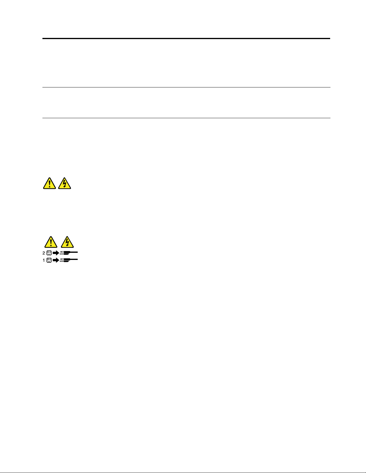
•Connectanddisconnectcablesasdescribedinthefollowingtablewheninstalling,moving,oropening
coversonthisproductorattacheddevices.
Toconnect:Todisconnect:
1.TurneverythingOFF.
2.First,attachallcablestodevices.
3.Attachsignalcablestoconnectors.
4.Attachpowercordstooutlets.
5.TurndevicesON.
1.TurneverythingOFF.
2.First,removepowercordsfromoutlets.
3.Removesignalcablesfromconnectors.
4.Removeallcablesfromdevices.
Statement2
DANGER
Dangerofexplosionifbatteryisincorrectlyreplaced.
Whenreplacingthelithiumcoincellbattery,useonlythesameoranequivalenttypethatis
recommendedbythemanufacturer.Thebatterycontainslithiumandcanexplodeifnotproperly
used,handled,ordisposedof.
Donot:
•Throworimmerseintowater
•Heattomorethan100°C(212°F)
•Repairordisassemble
Disposeofthebatteryasrequiredbylocalordinancesorregulations.
©CopyrightLenovo2013
v
Page 8
Statement3
CAUTION:
Whenlaserproducts(suchasCD-ROMs,DVDdrives,beropticdevices,ortransmitters)are
installed,notethefollowing:
•Donotremovethecovers.Removingthecoversofthelaserproductcouldresultinexposureto
hazardouslaserradiation.Therearenoserviceablepartsinsidethedevice.
•Useofcontrolsoradjustmentsorperformanceofproceduresotherthanthosespeciedherein
mightresultinhazardousradiationexposure.
DANGER
SomelaserproductscontainanembeddedClass3AorClass3Blaserdiode.Notethefollowing:
Laserradiationwhenopen.Donotstareintothebeam,donotviewdirectlywithoptical
instruments,andavoiddirectexposuretothebeam.
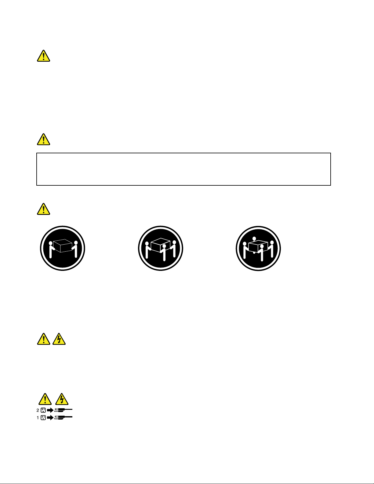
Statement4
≥18kg(39.7lb)≥32kg(70.5lb)≥55kg(121.2lb)
<32kg(70.5lb)<55kg(121.2lb)<100kg(220.5lb)
CAUTION:
Usesafepracticeswhenlifting.
Statement5
CAUTION:
Thepowercontrolbuttononthedeviceandthepowerswitchonthepowersupplydonotturnoff
theelectricalcurrentsuppliedtothedevice.Thedevicealsomighthavemorethanonepower
cord.Toremoveallelectricalcurrentfromthedevice,ensurethatallpowercordsaredisconnected
fromthepowersource.
viThinkServerTS140UserGuide
Page 9
Statement6
CAUTION:
Ifyouinstallastrain-reliefbracketoptionovertheendofthepowercordthatisconnectedtothe
device,youmustconnecttheotherendofthepowercordtoapowersourcethatiseasilyaccessible
incaseitneedstobedisconnected.
Statement7
CAUTION:
Ifthedevicehasdoors,ensurethatyouremoveorsecurethedoorsbeforemovingorliftingthe
devicetoprotectagainstpersonalinjury.Thedoorswillnotsupporttheweightofthedevice.
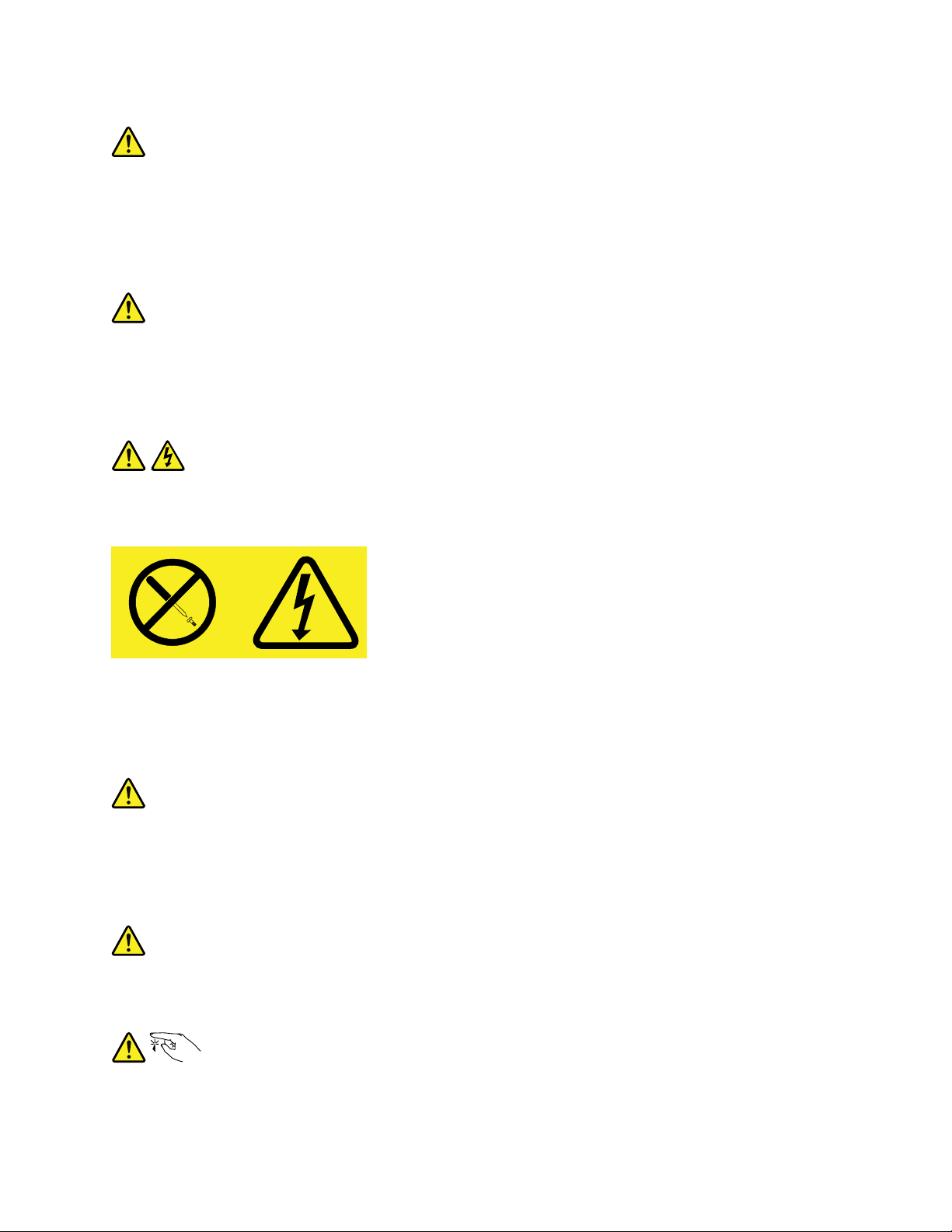
Statement8
CAUTION:
Neverremovethecoveronapowersupplyoranypartthathasthefollowinglabelattached.
Hazardousvoltage,current,andenergylevelsarepresentinsideanycomponentthathasthislabel
attached.Therearenoserviceablepartsinsidethesecomponents.Ifyoususpectaproblemwith
oneoftheseparts,contactaservicetechnician.
Statement9
CAUTION:
Disconnectthehot-swapfancablesbeforeremovingthefanfromthedevicetoprotectagainst
personalinjury.
Statement10
CAUTION:
Thefollowinglabelindicatesasharp-edgehazard.
©CopyrightLenovo2013
vii
Page 10
Statement11
CAUTION:
Thefollowinglabelindicatesapotentialheathazard.
Statement12
DANGER
Overloadingabranchcircuitisapotentialrehazardandashockhazardundercertainconditions.To
avoidthesehazards,ensurethatyoursystemelectricalrequirementsdonotexceedbranchcurrentratings
attheinstallationsite.
Statement13
CAUTION:
Ensurethattherackissecuredproperlytoavoidtippingwhentheserverunitisextendedontherails.
Statement14
CAUTION:
SomeaccessoryoroptionboardoutputsexceedClass2orlimitedpowersourcelimits.Y ou
mustinstalltheappropriateinterconnectingcablinginaccordancewithyourlocalelectricalcode
requirements.
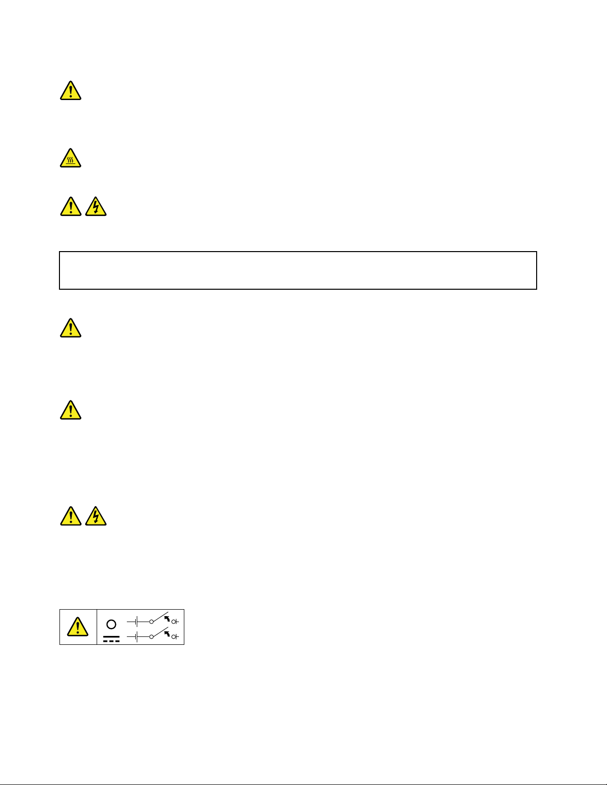
Statement15
CAUTION:
Thepower-controlbuttononthedevicemayputthedeviceinstandbymodeinsteadofturningoff
thedevice.Inaddition,thedevicemighthavemultipleconnectionstodcpower.T oremoveall
electricalcurrentfromthedevice,ensurethatallconnectionstodcpoweraredisconnectedat
thedcpowerinputterminals.
viiiThinkServerTS140UserGuide
Page 11
Statement16
CAUTION:
Toreducetheriskofelectricshockorenergyhazards:
•Thisequipmentmustbeinstalledbytrainedservicepersonnelinarestricted-accesslocation,as
denedbyyourlocalelectricalcodeandthelatesteditionofIEC60950.
•Connecttheequipmenttoareliablyearthedsafetyextralowvoltage(SELV)source.AnSELV
sourceisasecondarycircuitthatisdesignedsothatnormalandsinglefaultconditionsdonot
causethevoltagestoexceedasafelevel(60Vdirectcurrent).
•Thebranchcircuitovercurrentprotectionmustberatedinaccordancewithlocalelectricalcode
requirements.
•Use1.3mm
2
or16AmericanWireGauge(AWG)copperconductoronly,notexceeding3meters
inlength.
•T orquethewiring-terminalscrewsto1.4newton-metersor12inch-pounds.
•Provideareadilyavailable,approvedandrateddisconnectdeviceintheeldwiring.
Statement17
CAUTION:
ThisproductcontainsaClass1Mlaser.Donotviewdirectlywithopticalinstruments.
Statement18
CAUTION:
Donotplaceanyobjectontopofrack-mountedproducts.
Statement19
CAUTION:
Hazardousmovingparts.Keepngersandotherbodypartsaway.
©CopyrightLenovo2013
ix
Page 12

Statement20
CAUTION:
Alithiumionbatteryisprovided.T oavoidpossibleexplosion,donotburnthebattery.Replacethe
batteryonlywiththeLenovo-approvedpart.Recycleordiscardthebatteryasinstructedbylocal
regulations.
xThinkServerTS140UserGuide
Page 13

Chapter1.Generalinformation
Thischapterprovidessomegeneralinformationaboutyourserver.
Thischaptercontainsthefollowingtopics:
•“Introduction”onpage1
•“Serverdocumentation”onpage2
Introduction
ThisuserguideforyourLenovo
specications,componentlocations,congurationinstructions,hardwarereplacementprocedures,and
basictroubleshootinganddiagnostics.
YourservercomeswithadocumentationDVDthatcontainsvariousserverdocumentstohelpyouuseand
maintaintheserver.Meanwhile,yourservercomeswithaThinkServerEasyStartupDVDthatprovidesa
convenientsolutionforconguringtheserverandinstallinganoperatingsystem.
TheLenovoLimitedWarranty(LLW)containsthewarrantytermsthatapplytotheproductyoupurchasedfrom
Lenovo.ReadtheLLWonthedocumentationDVDthatcomeswithyourserver.Aprintablegenericversion
ofthelatestLLWalsoisavailableinmorethan30languagesathttp://www.lenovo.com/warranty/llw_02.If
youcannotobtaintheLLWthroughthedocumentationDVDorLenovoWebsite,contactyourlocalLenovo
ofceorresellertoobtainaprintedversionoftheLLW,freeofcharge.
®
ThinkServer
®
productcontainsinformationabouttheserverfeatures,
Forwarrantyservice,consulttheworldwideLenovoSupporttelephonelist.Telephonenumbersaresubject
tochangewithoutnotice.Themostup-to-datetelephonelistforLenovoSupportisalwaysavailableonthe
Websiteathttp://www.lenovo.com/support/phone.Ifthetelephonenumberforyourcountryorregionisnot
listed,contactyourLenovoresellerorLenovomarketingrepresentative.
Toobtainthemostup-to-dateinformationabouttheserver,goto:
http://www.lenovo.com/thinkserver
LenovomaintainspagesontheWorldWideWeb,whereyoucangetthelatesttechnicalinformationand
downloaddocumentationordevicedriversandupdates.ToaccesstheLenovoSupportWebsite,goto:
http://www.lenovo.com/support
Recordinformationabouttheserverinthefollowingtable.Youwillneedtheseinformationwhenyou
registertheserverwithLenovo.
Forwheretondtheproductinformationlabelonthechassis,see“Machinetype,model,andserialnumber
label”onpage11
.
©CopyrightLenovo2013
1
Page 14

Productname
______________________________________________
Machinetypeandmodel(MT-M)
Serialnumber(S/N)
Dateofpurchase
______________________________________________
______________________________________________
______________________________________________
YoucanregisteryourserverwithLenovobyfollowingtheinstructionsat:
http://www.lenovo.com/register
Whenyouregisteryourserver,informationisenteredintoadatabase,whichenablesLenovotocontact
youincaseofarecallorothersevereproblem.AfteryouregisteryourserverwithLenovo,youwillreceive
quickerservicewhenyoucallLenovoforhelp.Inaddition,somelocationsofferextendedprivilegesand
servicestoregisteredusers.
Serverdocumentation
Thistopicprovidesgeneraldescriptionsofthevariousdocumentationforyourserverandinstructionson
howtoobtainallthedocumentation.
Printeddocument
Thefollowingdocumentisprintedoutandcontainedinyourserverpackage.
ReadMeFirst
Thisisamultilingualdocumentyoushouldreadrst.Thisdocumentguidesyoutoreadthecomplete
warranty,support,andsafetyinformationonthedocumentationDVDthatcomeswithyourserverbefore
usingtheproduct.Thisdocumentalsoprovidesinformationabouthowtondthemostup-to-date
informationontheLenovoSupportWebsite.
DocumentationDVD
ThedocumentationDVD,whichcomeswithyourserver,containsvariousdocumentsforyourserverin
PortableDocumentFormat(PDF)andHyperTextMarkupLanguage(HTML).ThedocumentationDVDisnot
bootable.ToviewthedocumentsontheDVD,youwillneedacomputerwithaWebbrowserandtheAdobe
Readerprogram,whichisavailablefordownloadat:
http://www.adobe.com
TostartthedocumentationDVD,inserttheDVDintotheopticaldrive.TheDVDisAutoPlayenabledand
startsautomaticallyinmostMicrosoft
®
Linux
operatingsystem,openthelaunch.htmlelocatedintherootdirectoryoftheDVD.
®
Windows
®
environments.IftheDVDfailstostartorifyouareusinga
Note:LenovomaintainspagesontheWorldWideWeb,whereyoucangetthelatesttechnicalinformation
anddownloaddocumentationordevicedriversandupdates.Someinformationinthedocumentsonthe
documentationDVDmightchangewithoutnoticeaftertherstreleaseoftheDVD.Youcanalwaysobtainall
themostup-to-datedocumentationforyourserverfromtheLenovoWebsiteat:
http://www.lenovo.com/ThinkServerUserGuides
2ThinkServerTS140UserGuide
Page 15

ThefollowingdocumentsareonthedocumentationDVDthatcomeswithyourserver:
•Safety,Warranty,andSupportInformation
Thisisamultilingualdocumentthatincludesallthesafetystatementsforyourproductinmorethan30
languages.Besuretoreadandunderstandallthesafetystatementsbeforeusingtheproduct.This
documentalsoincludestheLenovowarrantystatement,CustomerReplaceableUnits(CRUs)information,
andinformationabouthowtocontacttheLenovoCustomerSupportCenter.
•LenovoLicenseAgreement
ThisdocumentincludesthetermsandconditionsoftheLenovoLicenseAgreement.
•UserGuide
Thisdocumentprovidesdetailedinformationtohelpyougetfamiliarwithyourserverandhelpyouuse,
congure,andmaintainyourserver.
Documentonlyfortrainedservicepersonnel
ThefollowingdocumentisintendedonlyfortrainedservicepersonnelofLenovo.
HardwareMaintenanceManual
Thisdocumentprovidesinformationaboutcomponentlocations,replacementproceduresformajorField
ReplaceableUnits(FRUs),andtroubleshootinganddiagnostics.Thisdocumentisupdatedfrequently,and
themostup-to-dateversionisalwaysavailableinEnglishontheLenovoWebsiteat:
http://www.lenovo.com/ThinkServerUserGuides
Chapter1.Generalinformation3
Page 16

4ThinkServerTS140UserGuide
Page 17

Chapter2.Serversetuproadmap
Thischapterprovidesageneralroadmaptoguideyouthroughsettingupyourserver.
Theserversetupprocedurevariesdependingonthecongurationoftheserverwhenitwasdelivered.In
somecases,theserverisfullyconguredandyoujustneedtoconnecttheservertothenetworkandan
acpowersource,andthenyoucanturnontheserver.Inothercases,theserverneedstohavehardware
featuresinstalled,requireshardwareandrmwareconguration,andrequiresanoperatingsystemto
beinstalled.
Thegeneralprocedureforsettingupyourserveris:
1.Unpacktheserverpackage.See“Serverpackage”onpage7.
2.Installanyrequiredhardwareorserveroption.SeetherelatedtopicsinChapter6“Installing,removing,
orreplacinghardware”onpage35
3.ConnecttheEthernetcableandpowercordstotheserver.See“Rearviewoftheserver”onpage
13tolocatetheconnectors.
4.Turnontheservertoverifyoperation.See“Turningontheserver”onpage19.
5.ReviewtheUniedExtensibleFirmwareInterface(UEFI)settingsandcustomizeasneeded.See
“StartingtheSetupUtilityprogram”onpage21
6.CongureRAIDandinstalltheoperatingsystemandbasicdrivers.See“ThinkServerEasyStartup”
onpage10and“ConguringRAID”onpage31.
7.Installanyadditionaldriversneededforaddedfeatures.Refertotheinstructionsthatcomewiththe
hardwareoption.
8.CongureEthernetsettingsintheoperatingsystembyreferringtotheoperatingsystemhelp.Thisstep
isnotrequirediftheoperatingsystemwasinstalledusingtheThinkServerEasyStartupprogram.
9.Checkforrmwareanddriverupdates.See“Updatingthermware”onpage34.
10.Installotherapplications.Refertothedocumentationthatcomeswiththeapplicationsthatyouwantto
install.
.
.
©CopyrightLenovo2013
5
Page 18

6ThinkServerTS140UserGuide
Page 19
Chapter3.Productoverview
Thischapterprovidesinformationabouttheserverpackage,features,specications,andsoftwareprograms.
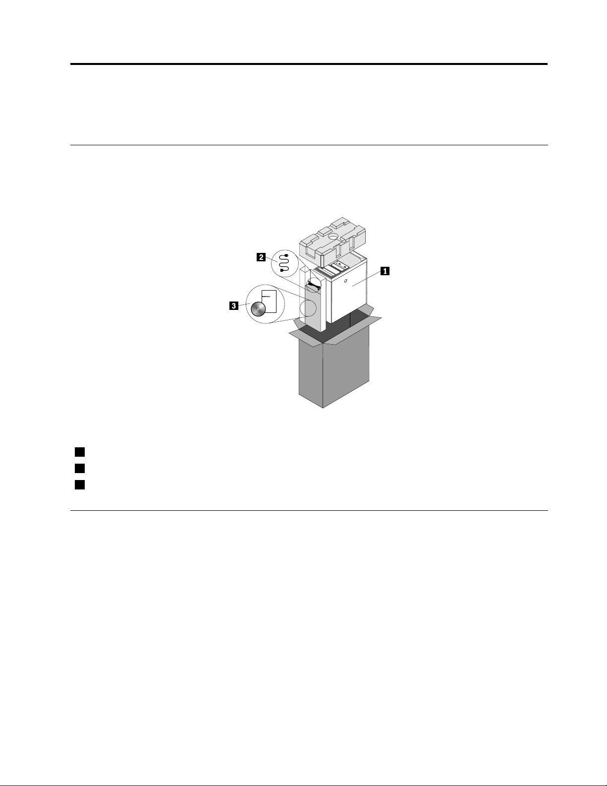
Serverpackage
Theserverpackageincludestheserver,apowercord,printeddocumentation,adocumentationDVD,and
softwaremedia.
Figure1.Serverpackage
1
Server
2
Powercord
3
Materialbox(includingprinteddocumentation,adocumentationDVD,andsoftwaremedia)
Features
Thistopicprovidesgeneralinformationabouttheserverfeaturesforvariousmodels.Dependingonyour
specicmodel,somefeaturesmightvaryornotbeavailable.Forinformationaboutyourspecicmodel,use
theSetupUtilityprogram.See“ViewinginformationintheSetupUtilityprogram”onpage21.
Microprocessor
Yourservercomeswithoneofthefollowingmicroprocessors(internalcachesizevariesbymodeltype):
•Intel
•IntelPentium
•IntelXeon
ForalistoftheThinkServermicroprocessoroptions,goto:
http://www.lenovo.com/thinkserver
®
Core™i3microprocessor
®
®
microprocessor
microprocessor
©CopyrightLenovo2013
7
Page 20

Memory
Yourserverhasfourmemoryslots.Formoreinformation,see“Installingorremovingamemorymodule”
onpage41.
Powersupply
Yourservercomeswithoneofthefollowingpowersupplycongurations:
•280-wattautomaticvoltage-sensingpowersupply
•450-wattautomaticvoltage-sensingpowersupply
Fans
Yourservercomeswiththefollowingfanstoprovidepropersystemcoolingandairow:
•Onefrontsystemfan
•Oneheatsinkandfanassembly
•Onerearsystemfan
Internaldrives
Internaldrivesaredevicesthatyourserverusestoreadandstoredata.Theinternaldrivessupported
byyourservervarybymodel.
•Harddiskdrive
Uptofour3.5-inchSerialAdvancedTechnologgyAttachment(SATA)harddiskdrives
•Opticaldrive
OneSATAopticaldriveinsomemodels
Forthelocationinformationabouttheinternaldrivesordrivebays,see“Internaldrives”onpage16.
Expansionslots
Theserverhasfourexpansionslotsonthesystemboard.Fordetailedinformation,see“Locatingpartson
thesystemboard”onpage15.
Input/Output(I/O)features
•One9-pinserialport
•OneEthernetconnector
•OneVideoGraphicsArray(VGA)monitorconnector
•SixUSB3.0connectors(twoonthefrontpanelandfourontherearpanel)
•Threeaudioconnectorsontherearpanel(audioline-inconnector,audioline-outconnector,and
microphoneconnector)
•TwoDisplayPortconnectors
•TwoUSB2.0connectorsontherearpanel
Forthelocationinformationabouttheconnectors,refertotherelatedtopicsin“Locations”onpage11
Videosubsystem
IntegratedgraphicsforaVGAconnectorandtwoDisplayPortconnectors
8ThinkServerTS140UserGuide
.
Page 21

Ethernetconnectivity
OneRJ-45Ethernetconnectorontherearpanelwith100Mbpsor1000Mbpsnetworkconnectivity.
Formoreinformation,see“Rearviewoftheserver”onpage13
.
Reliability,availability,andserviceability
Reliability,availability,andserviceability(hereinafterreferredtoasRAS)arethreeimportantserverdesign
features.TheRASfeatureshelpyoutoensuretheintegrityofthedatastoredontheserver,theavailabilityof
theserverwhenyouneedit,andtheeasewithwhichyoucandiagnoseandcorrectproblems.
YourserverhasthefollowingRASfeatures:
•Securityfeatures
–Administratorpasswordanduserpasswordtohelpprotectunauthorizedaccesstotheserver(see
“Usingpasswords”onpage25
)
–ThinkServerTrustedPlatformModule(TPM),whichisasecuritychip,tohelpenhanceserversecurity
Note:TheTPMisonlyavailableinsomemodels.
–Remotemonitoringorcontrolbyanadministratortoprovideprotectionorhelp
•Basicsystemmanagementfeatures
–Abilitytostorethepower-onself-test(POST)hardwaretestresults
–BIOSSetupUtilityprogram
TheBIOSSetupUtilityprogramhelpsyouviewtheserverinformationandconguretheserverinthe
pre-operatingsystemenvironment.See“UsingtheSetupUtilityprogram”onpage21.
–IntelRapidStorageTechnologyenterprise(RSTe)
IntelRSTeisadevicedriverthatprovidessupportforSATAorSASRAID0,1,5,and10arrayson
specicIntelchipsetsystemboardstoenhanceharddiskdriveperformance.
–PrebootExecutionEnvironment(PXE)
TheIntelPXEtechnologyenablesyoutobootyourcomputers,loadanoperatingsystem,ordeploy
executableimagesfromaremoteserverbyusinganetworkinterface.Theoperationcanbedone
independentlyoflocaldatastoragedevices(suchasharddiskdrives)oroperatingsystems.
–Softwareprograms
Formoreinformationaboutthesoftwareprograms,see“Software”onpage10
.
–WakeonLAN
WhentheWakeonLANfeatureisenabledonacomputerthatisconnectedtoaLAN,anetwork
administratorcanremotelyturnonorwakeupthecomputerfromamanagementconsoleusingremote
networkmanagementsoftware.Besides,manyotherfunctions,suchasdatatransferandsoftware
updates,canbeperformedremotelywithoutremoteattendanceandcanbedoneafternormalworking
hoursandonweekendstosavetimeandincreaseproductivity.
Chapter3.Productoverview9
Page 22

Specications
Thistopicliststhephysicalspecicationsforyourserver.
Dimensions
Width:175mm(6.89inches)
Height:375mm(14.76inches)
Depth:431mm(16.97inches)
Weight
Theproductweightvariesdependingondifferentsystemcongurations.
Maximumcongurationwithoutpackage:13kg(28.66lb)
Maximumcongurationwithpackage:15.5kg(34.17lb)
Environment
•Airtemperature:
Operating:10°Cto35°C(50°Fto95°F)
Storage:-40°Cto70°C(-40°Fto158°F)inoriginalshippingpackage
•Altitude:0to3048m(0to10000ft)inanunpressurizedenvironment
•Humidity:
Operating:8%to80%(non-condensing)
Storagewithoutpackage:8%to80%(non-condensing)
Storagewithpackage:8%to90%(non-condensing)
Electricalinput
Universalinput:
•Lowrange:
Minimum:100Vac
Maximum:127Vac
Inputfrequencyrange:50to60Hz
•Highrange:
Minimum:200Vac
Maximum:240Vac
Inputfrequencyrange:50to60Hz
Software
Thistopicprovidesinformationaboutthesoftwareprogramsthatyoucanusetosetup,use,andmaintain
theserver.
ThinkServerEasyStartup
TheThinkServerEasyStartupprogramsimpliestheprocessofconguringRAIDandinstallingsupported
operatingsystemsanddevicedriversonyourserver.Thisprogramisprovidedwithyourserveron
aself-starting(bootable)ThinkServerEasyStartupDVD.Theuserguidefortheprogramalsoisonthe
DVDandcanbeaccesseddirectlyfromtheprograminterface.Fordetailedinformation,see“Usingthe
ThinkServerEasyStartupprogram”onpage28
.
10ThinkServerTS140UserGuide
Page 23

ThinkServerEasyUpdateFirmwareUpdater
TheThinkServerEasyUpdateFirmwareUpdaterprogram(hereinafterreferredtoastheFirmwareUpdater
program)enablesyoutomaintainyourserverrmwareup-to-dateandhelpsyouavoidunnecessaryserver
outages.TheFirmwareUpdaterprogramisavailablefordownloadingfromtheLenovoSupportWebsite.
FormoreinformationaboutdownloadingandusingtheFirmwareUpdaterprogram,see“Updatingthe
rmware”onpage34
.
BIOSupdateutilities
TheBIOSrmwarekeepsupdatingaftertheshipmentoftheserver.LenovomaintainspagesontheSupport
WebsiteandprovidestheBIOSupdateutilitieswithinstructionsfordownloadtohelpyouupdatethe
BIOSrmwareifneeded.Formoreinformation,see“Updatingthermware”onpage34and“Updatingor
recoveringtheBIOS”onpage27
.
RAIDcongurationutilities
YourserversupportsonboardSATAsoftwareRedundantArrayofIndependentDisks(RAID).Fordetailed
information,see“ConguringRAID”onpage31
.
Diagnosticprograms
Thefollowingdiagnosticprogramsareavailableforyoutodiagnoseserverproblems:
•ThinkServerDiagnosticT ool
•ThinkServerSystemProleCollectionT ool
Formoreinformation,see“Usingadiagnosticprogram”onpage83.
Locations
Thistopicprovidesinformationtohelpyoulocateyourservercomponents.
Machinetype,model,andserialnumberlabel
Thistopichelpsyoulocatethelabelthatcontainsthemachinetype,model,andserialnumberinformation
foryourserver.
WhenyoucontactLenovoforhelp,themachinetype,model,andserialnumberinformationhelpssupport
technicianstoidentifyyourserverandprovidefasterservice.
Chapter3.Productoverview11
Page 24
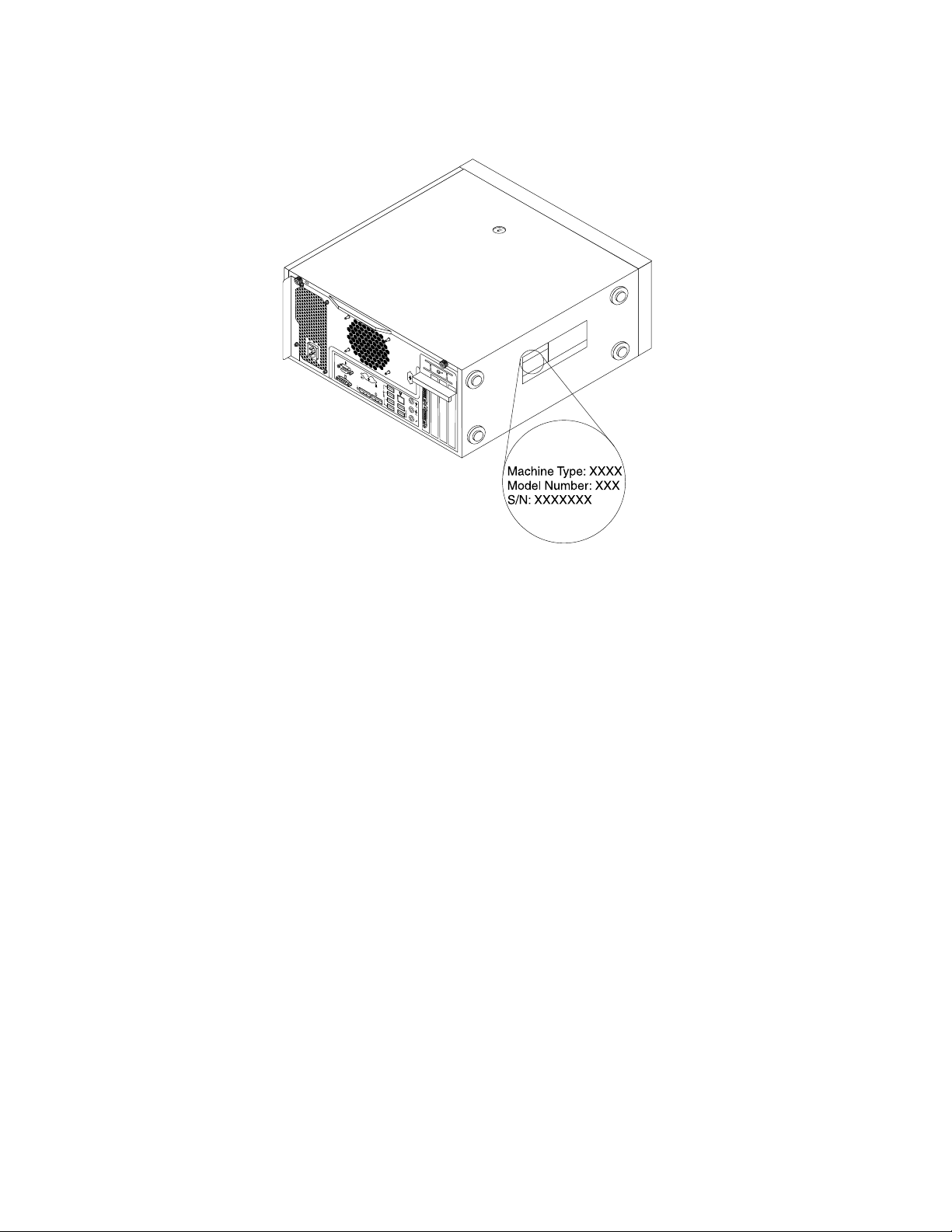
Thefollowingisasampleofthemachinetype,model,andserialnumberlabel.
Figure2.Machinetype,model,andserialnumberlabel
Frontviewoftheserver
Thistopicprovidesinformationtohelpyoulocatethepartsonthefrontoftheserver.
12ThinkServerTS140UserGuide
Page 25
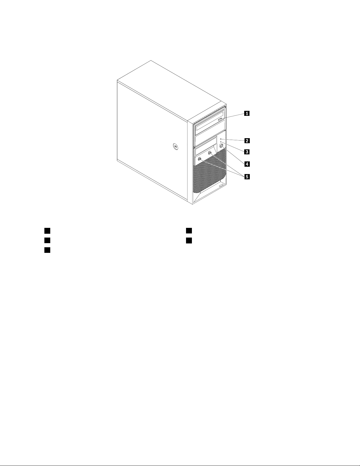
Thefollowingillustrationshowsthefrontviewoftheserver.
Figure3.Frontviewoftheserver
1Opticaldriveeject/closebutton
2HarddiskdriveactivityLED
3Power-onLED
4Powerbutton
5USB3.0connectors(2)
Rearviewoftheserver
Thistopicprovidesinformationtohelpyoulocatetheconnectorsandcomponentsontherearofyourserver.
Figure4“Rearconnectorlocations”onpage14showsthelocationsoftheconnectorsontherearof
yourserver.Someconnectorsontherearofyourserverarecolor-codedtohelpyoudeterminewhere
toconnectthecablesonyourserver.
Chapter3.Productoverview13
Page 26
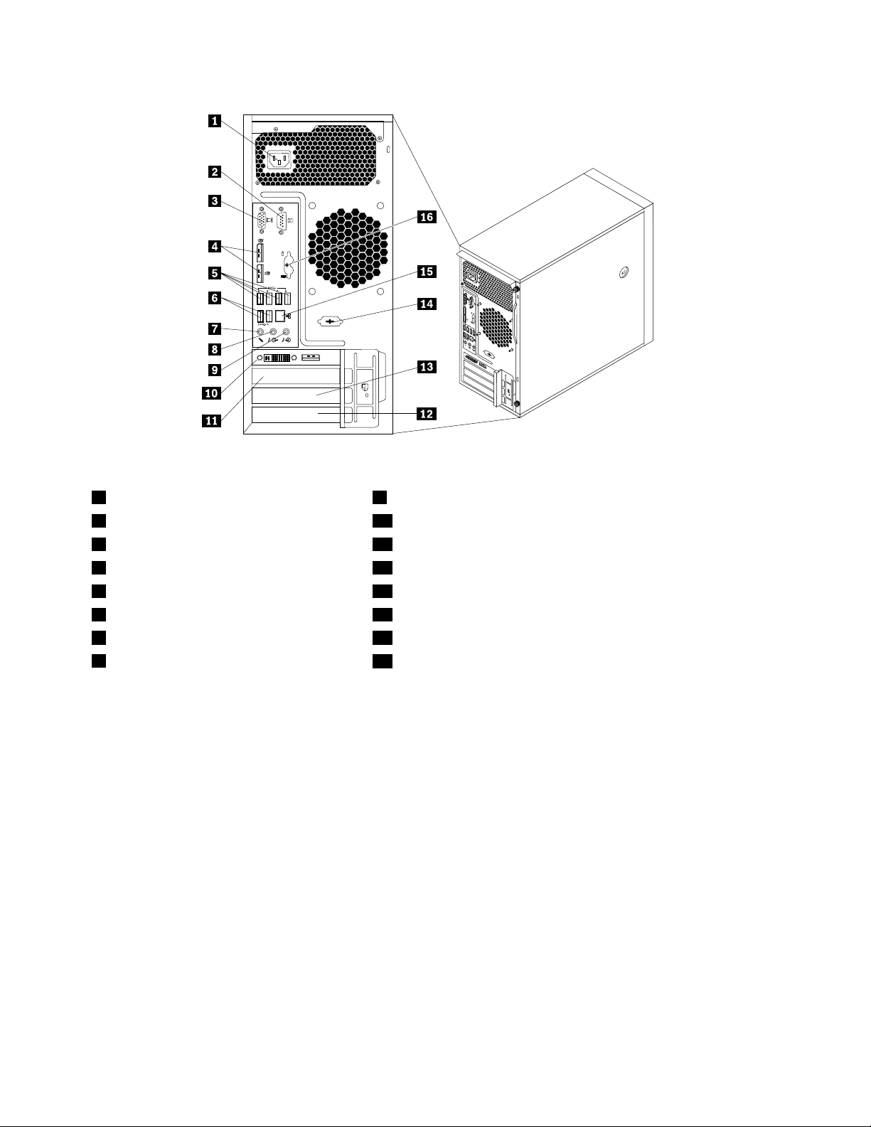
Figure4.Rearconnectorlocations
1Powercordconnector9Audioline-inconnector
2Serialconnector10PCIExpressx16graphicscard(availableinsomemodels)
3VGAmonitorconnector11PCIExpressx1cardslotbracket
4DisplayPortconnectors(2)12PCIcardslotbracket
5USB3.0connectors(4)13PCIExpressx4cardslotbracket
6USB2.0connectors(2)14Optionalserialconnector
7Microphoneconnector15Ethernetconnector
8Audioline-outconnector
16PS/2keyboardandmouseconnectors(optional)
ConnectorDescription
Audioline-inconnector
Usedtoreceiveaudiosignalsfromanexternalaudiodevice,suchasastereo
system.Whenyouattachanexternalaudiodevice,acableconnectstheaudio
line-outconnectorofthedevicetotheaudioline-inconnectoroftheserver.
Audioline-outconnector
Usedtosendaudiosignalsfromtheservertoexternaldevices,suchaspowered
stereospeakers(speakerswithbuilt-inampliers),headphones,multimedia
keyboards,ortheaudioline-inconnectoronastereosystemorotherexternal
recordingdevice.
DisplayPortconnector
Usedtoattachahigh-performancemonitor,adirect-drivemonitor,orotherdevices
thatuseaDisplayPortconnector.
Ethernetconnector
UsedtoattachanEthernetcableforalocalareanetwork(LAN).
Note:TooperatetheserverwithinFCCClassBlimits,useaCategory5Ethernet
cable.
Microphoneconnector
Usedtoattachamicrophonetoyourserverwhenyouwanttorecordsoundorif
youusespeech-recognitionsoftware.
Serialconnector
Usedtoattachanexternalmodem,aserialprinter,orotherdevicesthatusea
9-pinserialconnector.
14ThinkServerTS140UserGuide
Page 27
ConnectorDescription
USBconnectorUsedtoattachadevicethatrequiresaUSBconnector,suchasaUSBkeyboard,a
USBmouse,aUSBscanner,oraUSBprinter.IfyouhavemorethaneightUSB
devices,youcanpurchaseaUSBhub,whichyoucanusetoconnectadditional
USBdevices.
VGAmonitorconnectorUsedtoattachaVGAmonitororotherdevicesthatuseaVGAmonitorconnector.
Locatingpartsonthesystemboard
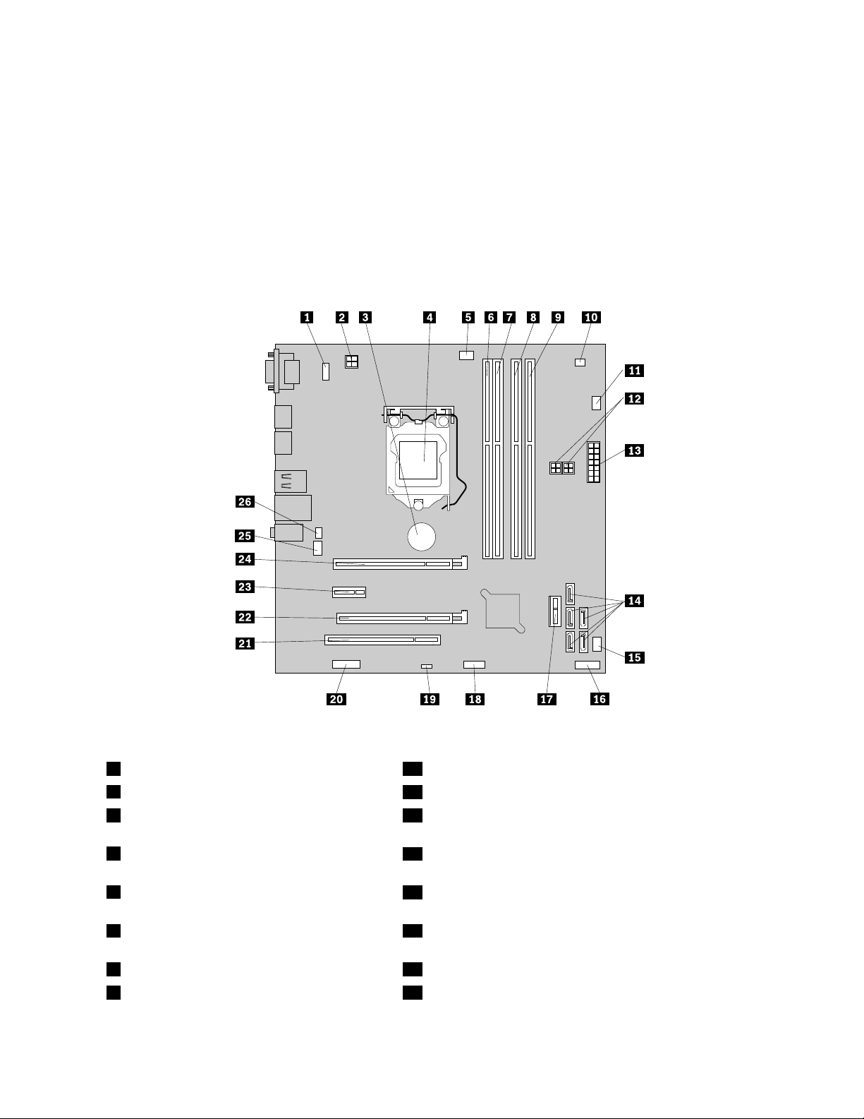
Figure5“Systemboardpartlocations”onpage15showsthelocationsofthepartsonthesystemboard.
Figure5.Systemboardpartlocations
1PS/2keyboardandmouseconnector14SA TA3.0connectors0to4
24-pinpowerconnector
3Systemboardbattery16Frontpanelconnector(forconnectingtheLEDsandpower
15Powerfanconnector
buttononthefrontoftheserver)
4Microprocessor
17FrontUSB3.0connector(forconnectingtheUSBconnectors
onthefrontoftheserver)
5Microprocessorfanconnector
18FrontUSB2.0connector(forconnectinganadditionalUSB
device)
6Memoryslot1(DIMM1)19ClearCMOS(ComplementaryMetalOxideSemiconductor)
/Recoveryjumper
7Memoryslot2(DIMM2)20Serial(COM2)connector
8Memoryslot3(DIMM3)21PCIcardslot
Chapter3.Productoverview15
Page 28
9Memoryslot4(DIMM4)22PCIExpressx4cardslot
10Thermalsensorconnector
11Harddiskdrivefanconnector
124-pinSATApowerconnectors(2)25Systemfanconnector
1314-pinpowerconnector
23PCIExpressx1cardslot
24PCIExpressx16cardslot
26Coverpresenceswitchconnector(intrusionswitchconnector)
Internalcomponents
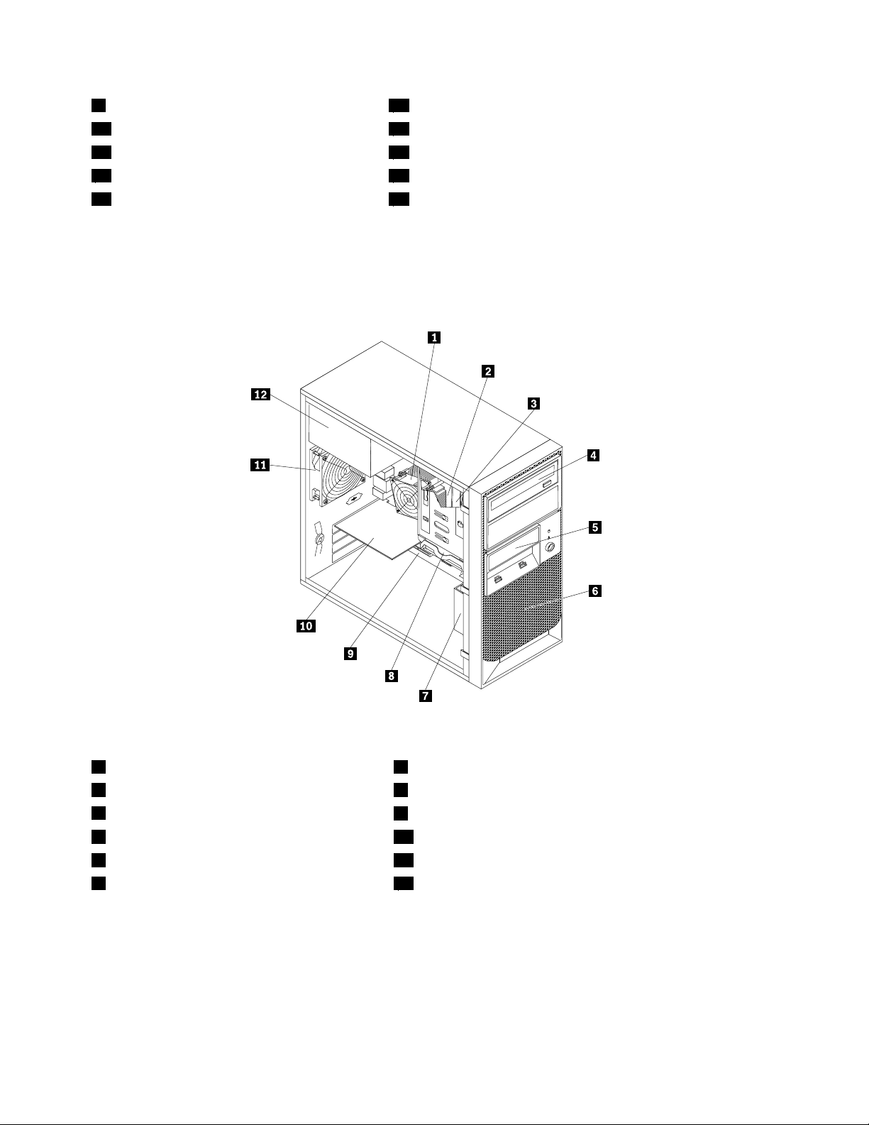
Figure6“Componentlocations”onpage16showsthelocationsofthevariouscomponentsinyourserver.
Toremovetheservercoverandaccesstheinsideoftheserver,see“Removingtheservercover”onpage37
.
Figure6.Componentlocations
1Heatsinkandfanassembly7Frontfanassembly
2Microprocessor8Harddiskdrive
3Memorymodule
4Opticaldrive10Graphicscard(availableinsomemodels)
5Cardreaderdrivebay
6Frontbezel12Powersupplyassembly
9Systemboard
11Rearfanassembly
Internaldrives
Internaldrivesaredevicesthatyourserverusestoreadandstoredata.Youcanadddrivestoyourserver
toincreasestoragecapacityandenableyourservertoreadothertypesofmedia.Internaldrivesare
installedinbays.
16ThinkServerTS140UserGuide
Page 29
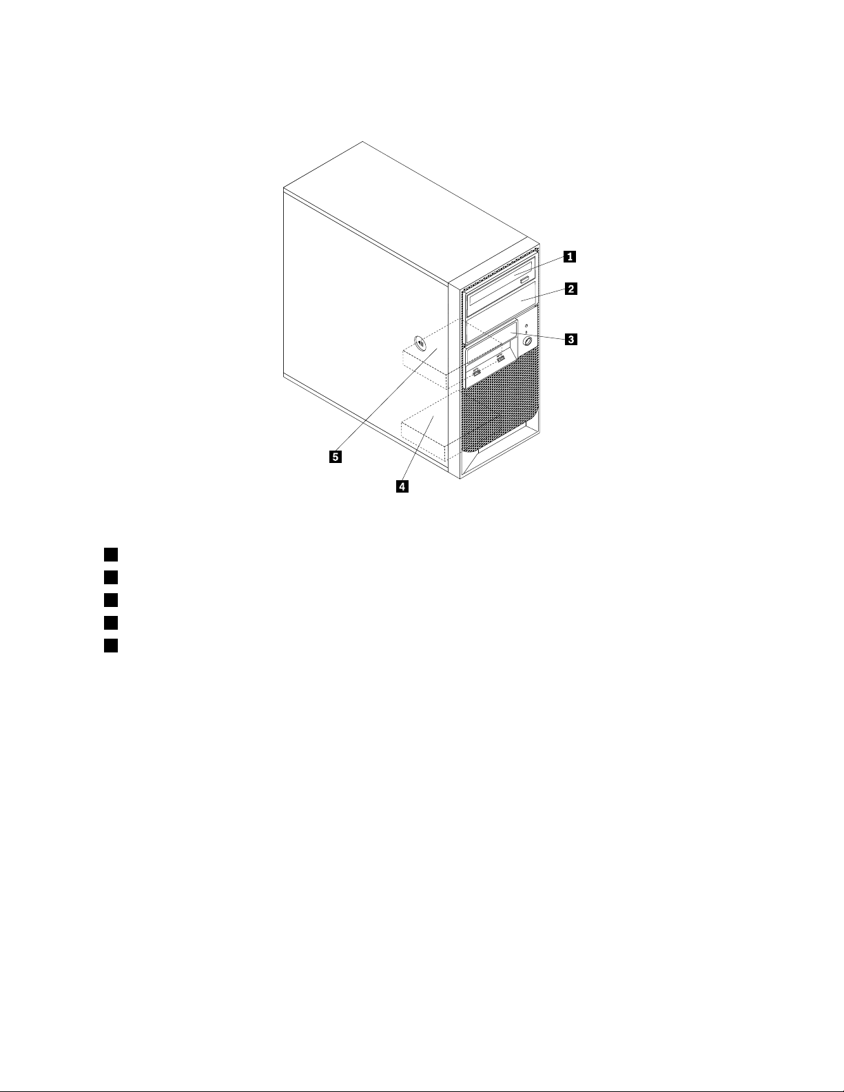
Figure7“Drivebaylocations”onpage17showsthelocationsofthedrivebays.
Figure7.Drivebaylocations
1Opticaldrivebay
2Secondaryopticaldrivebay
3Cardreaderdrivebay
4SecondarySATAharddiskdrivebay
5PrimarySATAharddiskdrivebay(witha3.5-inchSATAharddiskdriveinstalled)
Chapter3.Productoverview17
Page 30

18ThinkServerTS140UserGuide
Page 31
Chapter4.Turningonandturningofftheserver
Thischapterprovidesinformationaboutturningonandturningofftheserver.
Turningontheserver
Aftertheserverisconnectedtoanacpowersource,youcanturnontheserverbypressingthepowerbutton.
Turningofftheserver
Toremoveallpowerfromtheserver,youmustdisconnectthepowercordfromtheserver.
Someoperatingsystemsrequireanorderlyshutdownbeforeyouturnofftheserver.Seeyouroperating
systemdocumentationforinformationaboutshuttingdowntheoperatingsystem.
Statement5
CAUTION:
Thepowercontrolbuttononthedeviceandthepowerswitchonthepowersupplydonotturnoff
theelectricalcurrentsuppliedtothedevice.Thedevicealsomighthavemorethanonepower
cord.Toremoveallelectricalcurrentfromthedevice,ensurethatallpowercordsaredisconnected
fromthepowersource.
Theservercanbeturnedoffinanyofthefollowingways:
•Youcanturnofftheserverfromtheoperatingsystem,ifyouroperatingsystemsupportsthisfeature.After
anorderlyshutdownoftheoperatingsystem,theserverwillturnoffautomatically.
•Youcanpressthepowerbuttontostartanorderlyshutdownoftheoperatingsystemandturnoffthe
server,ifyouroperatingsystemsupportsthisfeature.
•Iftheoperatingsystemstopsfunctioning,youcanpressandholdthepowerbuttonformorethanfour
secondstoturnofftheserver.
©CopyrightLenovo2013
19
Page 32

20ThinkServerTS140UserGuide
Page 33

Chapter5.Conguringtheserver
Thischapterprovidesthefollowinginformationtohelpyouconguretheserver:
•“UsingtheSetupUtilityprogram”onpage21
•“UsingtheThinkServerEasyStartupprogram”onpage28
•“ConguringRAID”onpage31
•“UsingtheFirmwareUpdaterprogram”onpage34
UsingtheSetupUtilityprogram
ThistopicprovidesinformationaboutusingtheSetupUtilityprogram.
TheSetupUtilityprogramispartoftheserverrmware.YoucanusetheSetupUtilityprogramtoviewand
changethecongurationsettingsofyourserver,regardlessofwhichoperatingsystemyouareusing.
However,theoperatingsystemsettingsmightoverrideanysimilarsettingsintheSetupUtilityprogram.
StartingtheSetupUtilityprogram
ThistopicprovidesinstructionsonhowtostarttheSetupUtilityprogram.
TostarttheSetupUtilityprogram,dothefollowing:
1.Connecttheservertoanacpowersourceandpressthepowerswitchonthefrontpaneltoturnonthe
server.See“Turningontheserver”onpage19.
2.PresstheF1keyassoonasyouseethelogoscreen.Then,waitforseveralseconds,andtheSetup
Utilityprogramopens.Ifyouhavesetapassword,youneedtotypethecorrectpasswordtoenterthe
SetupUtilityprogram.Forpasswordinformation,see“Usingpasswords”onpage25.
ViewinginformationintheSetupUtilityprogram
TheSetupUtilityprogrammenulistsvariousitemsaboutthesystemconguration.Selectadesireditem
toviewinformationorchangesettings.
WhenworkingwiththeSetupUtilityprogram,youmustusethekeyboard.Thekeysusedtoperformvarious
tasksaredisplayedontherightbottompaneofeachscreen.YoualsocanpresstheF1keyforgeneralhelp
aboutthekeys.Formostitems,thecorrespondinghelpmessageisdisplayedontherighttoppaneofthe
screenwhentheitemisselected.Iftheitemhassubmenus,youcandisplaythesubmenusbypressingEnter.
YoucanviewthefollowinginformationaboutyourspecicservermodelintheSetupUtilityprogram:
•TheMainmenulistsinformationaboutsystemsummary,theBIOSversion,machinetypeandmodel,and
systemdateandtime.
OntheSystemSummarymenu,selectInstalledMemoryandfollowtheinstructionsonthescreento
viewinformationabouttheinstalledmemorymodules.
•OntheAdvancedmenu,selectCPUSetupandfollowtheinstructionsonthescreentoviewinformation
abouttheinstalledmicroprocessoranditssupportedtechnologies.
•OntheDevicesmenu,selectATADriveSetupandfollowtheinstructionsonthescreentoview
informationabouttheinstalledSATAorSASdevices,suchasaharddiskdriveoranopticaldrive.
©CopyrightLenovo2013
21
Page 34

SetupUtilityprograminterface
ThistopicprovidesgeneralinformationaboutthemenusanditemsintheSetupUtilityprogram.
DependingontheBIOSversionofyourserver,somemenuoriteminformationmightdifferslightlyfrom
theinformationinthistopic.
Notes:
•Thedefaultsettingsalreadyareoptimizedforyou.Usethedefaultvalueforanyitemyouarenotfamiliar
with.Donotchangethevalueofunfamiliaritemstoavoidunexpectedproblems.Ifyouconsiderchanging
theserverconguration,proceedwithextremecaution.Settingthecongurationincorrectlymightcause
unexpectedresults.IfyoucannotturnontheserverbecauseofincorrectBIOSsettings,usetheClear
CMOSjumpertorestoretheBIOSsettingstothefactorydefaultsettings.See“Locatingpartsonthe
systemboard”onpage15
•Ifyouhavechangedanyhardwareintheserver,youmightneedtoreashtheBIOS.
TheSetupUtilityprogrammaininterfaceconsistsofthefollowingmenus:
•“Mainmenu”onpage22
•“Devicesmenu”onpage22
•“Advancedmenu”onpage23
•“Powermenu”onpage24
•“Securitymenu”onpage23
•“Startupmenu”onpage24
•“Exitmenu”onpage24
.
LenovoprovidestheBIOSupdateutilityontheLenovoSupportWebsite.Y oucandownloadtheBIOS
updateutilitytoupdatetheBIOSifthenewerBIOSversionspecicallysolvesaproblemyouhave.See
“UpdatingorrecoveringtheBIOS”onpage27
IfthepowertoyourserverisinterruptedwhiletheBIOSisbeingupdatedandyourservercannotstart
correctly,usetheBIOSrecoveryswitchtorecoverfromaBIOSupdatefailure.See“Recoveringfroma
BIOSupdatefailure”onpage28.
.
Mainmenu
AfterenteringtheSetupUtilityprogram,youcanseetheMainmenu,whichlistsbasicinformationabout
theBIOSandBMC,totalmemorysize,andsystemdateandtime.
TosetthesystemdateandtimeontheMainmenu,see“Settingthesystemdateandtime”onpage24.
Devicesmenu
YoucanvieworchangevariousdevicesettingsontheDevicesmenuintheSetupUtilityprogram.Oneach
submenu,pressEntertoviewtheinformationorshowselectableoptionsandselectadesiredoptionby
usingtheupanddownarrowkeys.Someitemsaredisplayedonthemenuonlyiftheserversupportsthe
correspondingfeatures.
TheDevicesmenucontainsthefollowingsubmenus.Formoreinformation,enterthecorresponding
submenuandrefertotheinstructionsonthescreen.
•SerialPortSetup:Viewandsetserialportcongurationparameters.
•USBSetup:ViewandsetUSBcongurationparameters.
•A TADriveSetup:ViewandsetSATAharddiskdrivecongurationparameters.
22ThinkServerTS140UserGuide
Page 35

•VideoSetup:Viewandsettheprimaryvideoadaptertype.
•AudioSetup:Enableordisabletheonboardaudiocontroller.
•NetworkSetup:EnableordisabletheonboardEthernetcontrollerandothernetworkfeatures.
Advancedmenu
YoucanvieworchangevariousservercomponentsettingsontheAdvancedmenuintheSetupUtility
program.TheAdvancedmenucontainsvariouscongurationsubmenusanditems.Oneachsubmenu,
pressEntertoshowselectableoptionsandselectadesiredoptionbyusingtheupanddownarrow
keysortypedesiredvaluesfromthekeyboard.Someitemsaredisplayedonthemenuonlyiftheserver
supportsthecorrespondingfeatures.
Notes:
•Enabledmeansthatthefunctioniscongured.
•Disabledmeansthatthefunctionisnotcongured.
TheAdvancedmenucontainsthefollowingsubmenus.Formoreinformation,enterthecorresponding
submenuandrefertotheinstructionsonthescreen.
•CPUSetup:ViewandsetCPUsetupcongurationparameters.
•Intel
•Intel
•CPUCRIDSupport:EnableordisabletheCPUCRIDSupportfeature.
•ChipsetCRIDSupport:EnableordisabletheChipsetCRIDSupportfeature.
®
Manageability:ViewandsetIntelManageabilitycongurationparameters.
®
SIPPSupport:EnableordisabletheIntelSIPPSupportfeature.
Securitymenu
YoucansetpasswordsandcongureothersecurityfeaturesontheSecuritymenuintheSetupUtility
program.Foreachmenuitem,pressEntertoshowselectableoptionsandselectadesiredoptionbyusing
theupanddownarrowkeysortypedesiredvaluesfromthekeyboard.Someitemsaredisplayedonthe
menuonlyiftheserversupportsthecorrespondingfeatures.
Notes:
•Enabledmeansthatthefunctioniscongured.
•Disabledmeansthatthefunctionisnotcongured.
TheSecuritymenucontainsthefollowingmainitems:
•AdministratorPassword:Viewthestatusofanadministratorpassword.
•Power-OnPassword:Viewthestatusofauserpassword.
•SetAdministratorPassword:Setanadministratorpasswordtoprotectagainstunauthorizedaccessto
yourserver.See“Usingpasswords”onpage25.
•SetPower-OnPassword:Setauserpasswordtoprotectagainstunauthorizedaccesstoyourserver.
See“Usingpasswords”onpage25
•ChassisIntrusionDetection:EnableordisabletheChassisIntrusionDetectionfeature.
TheSecuritymenucontainsthefollowingsubmenus:
•TCGFeatureSetup:ConguretheTPMfunction.See“ConguringtheTPMfunction”onpage26
•SystemEventLog:Viewandclearthesystemeventlog.
•SecureBoot:Viewandsetsecurebootcongurationparameters.
.
.
Chapter5.Conguringtheserver23
Page 36

Powermenu
ThePowermenuintheSetupUtilityprogramprovidesaninterfacetohelpyouvieworchangetheserver
poweroptions.
ThePowermenucontainsthefollowingitems:
•AfterPowerLoss:Viewandcongurethesystemperformanceafteracpowerisremovedandthe
restored.
•EnhancedPowerSavingMode:EnableordisableEnhancedPowerSavingMode.
ThePowermenucontainsthefollowingsubmenus:
•IntelligentCoolingEngine(ICE):Enablethesystemtoentertheloweracousticlevelorbetterthermal
level.
•AutomaticPowerOn:EnableordisabletheAutomaticPowerOnfeatures.
Startupmenu
TheStartupmenuintheSetupUtilityprogramlistsallthebootabledevicesinstalledinyourserverand
thelisteditemsvarydependingonyourserverconguration.Ifyouselectadesireddevicelistedonthis
menu,theserverwillstartfromthedeviceyouselect.
YoucanpressF12whenturningontheserverandselectatemporarystartupdevicefromthebootdevice
selectionwindow.See“Selectingastartupdevice”onpage26.
Exitmenu
AfteryounishviewingorchangingsettingsintheSetupUtilityprogram,youcanchooseadesiredaction
fromtheExitmenutosavechanges,discardchanges,orloaddefaultvalues,andexittheprogram.Press
EntertoselecttheitemontheExitmenuandthenselectYeswhenpromptedtoconrmtheaction.For
informationaboutexitingtheSetupUtilityprogram,see“ExitingfromtheSetupUtilityprogram”onpage27
TheExitmenucontainsthefollowingitems:
•SaveChangesandExit:SavechangesandexittheSetupUtilityprogram.
•DiscardChangesandExit:Discardchanges,loadpreviousvalues,andthenexittheSetupUtility
program.
•LoadOptimalDefaults:Restoretheuserdefaultvaluesforalltheitems.
•OSOptimizedDefaults:SelectEnabledtomeettheMicrosoftWindows8certicationrequirement.The
settingsfortheCSMsupport,bootmode,bootpriority,secureboot,andsecurityRollBackprevention
willbeaffected.
Settingthesystemdateandtime
ThistopicprovidesinstructionsonhowtosetthesystemdateandtimeintheSetupUtilityprogram.
TosetthesystemdateandtimeintheSetupUtilityprogram,dothefollowing:
1.StarttheSetupUtilityprogram.See“StartingtheSetupUtilityprogram”onpage21.
2.OntheMainmenu,selectSystemTime&Date.
3.UsetheTabkeytoswitchbetweendataelementsandtypethenumbersfromthekeyboardtosetthe
systemdateandtime.
4.PressF10tosavesettingsandexittheSetupUtilityprogram.
.
24ThinkServerTS140UserGuide
Page 37

Usingpasswords
ByusingtheSetupUtilityprogram,youcansetpasswordstopreventunauthorizedaccesstoyourcomputer
anddata.Thefollowingtypesofpasswordsareavailable:
•Power-OnPassword
•AdministratorPassword
Youdonothavetosetanypasswordstouseyourcomputer.However,usingpasswordsimproves
computingsecurity.Ifyoudecidetosetanypasswords,readthefollowingsections.
Passwordconsiderations
Apasswordcanbeanycombinationofupto64alphabeticandnumericcharacters.Forsecurityreasons,it
isrecommendedtouseastrongpasswordthatcannotbeeasilycompromised.Tosetastrongpassword,
usethefollowingguidelines:
•Haveatleasteightcharactersinlength
•Containatleastonealphabeticcharacterandonenumericcharacter
•SetupUtilityprogramandharddiskdrivepasswordsarenotcasesensitive
•Notbeyournameoryourusername
•Notbeacommonwordoracommonname
•Besignicantlydifferentfromyourpreviouspasswords
Power-OnPassword
WhenaPower-OnPasswordisset,youarepromptedtotypeavalidpasswordeachtimethecomputeris
turnedon.Thecomputercannotbeuseduntilthevalidpasswordistypedin.
AdministratorPassword
SettinganAdministratorPassworddetersunauthorizedusersfromchangingcongurationsettings.Ifyou
areresponsibleformaintainingthecongurationsettingsofseveralcomputers,youmightwanttosetan
AdministratorPassword.
WhenanAdministratorPasswordisset,youarepromptedtotypeavalidpasswordeachtimeyoutryto
accesstheSetupUtilityprogram.TheSetupUtilityprogramcannotbeaccesseduntilavalidpassword
istypedin.
IfboththePower-OnPasswordandAdministratorPasswordareset,youcantypeeitherpassword.However,
youmustuseyourAdministratorPasswordtochangeanycongurationsettings.
Setting,changing,anddeletingapassword
Toset,change,ordeleteapassword,dothefollowing:
1.StarttheSetupUtilityprogram.See“StartingtheSetupUtilityprogram”onpage21.
2.FromtheSetupUtilityprogrammainmenu,selectSecurity.
3.Dependingonthepasswordtype,selectSetPower-OnPasswordorSetAdministratorPassword.
4.Followtheinstructionsontherightsideofthescreentoset,change,ordeleteapassword.
Note:Apasswordcanbeanycombinationofupto64alphabeticandnumericcharacters.Formore
information,see“Passwordconsiderations”onpage25.
Erasinglostorforgottenpasswords(clearingCMOS)
Thissectionprovidesinstructionsonhowtoeraselostorforgottenpasswords,suchasauserpassword.
Chapter5.Conguringtheserver25
Page 38

Toerasealostorforgottenpassword,dothefollowing:
1.Removeallmediafromthedrivesandturnoffallattacheddevicesandtheserver.Then,disconnectall
powercordsfromelectricaloutletsanddisconnectallcablesthatareconnectedtotheserver.
2.Removetheservercover.See“Removingtheservercover”onpage37.
3.LocatetheClearCMOS/Recoveryjumperonthesystemboard.See“Locatingpartsonthesystem
board”onpage15
4.RemoveallpartsanddisconnectallcablesthatmightpreventyouraccesstotheClearCMOS
/Recoveryjumper.
5.Movethejumperfromthestandardposition(pin1andpin2)tothemaintenanceposition(pin2and
pin3).
6.Reinstallallpartsandreconnectallcablesthathavebeenremoved.
7.Reinstalltheservercoverandreconnecttheserverpowercord.See“Completingthepartsreplacement”
onpage79.
8.Turnontheserverandleaveitonforapproximately10seconds.Then,turnofftheserverbyholdingthe
powerswitchforapproximatelyveseconds.
9.Repeatstep1throughstep4.
10.MovetheClearCMOS/Recoveryjumperbacktothestandardposition(pin1andpin2).
11.Reinstallallpartsandreconnectallcablesthathavebeenremoved.
12.Reinstalltheservercoverandconnectthepowercords.See“Completingthepartsreplacement”
onpage79
.
.
ConguringtheTPMfunction
TheTPMworksasahardwaresecuritysolutiontohelpyoutoencryptdataandprotecttheserver.
ToenabletheTPMfunctionintheSetupUtilityprogram,dothefollowing:
1.StarttheSetupUtilityprogram.See“StartingtheSetupUtilityprogram”onpage21.
2.OntheSecuritymenu,selectTCGFeatureSetup,andthenpressEnter.
3.SelectTCGSecurityFeatures.Then,settheTPMSupporttoActive.
4.PressF10tosavesettingsandexittheSetupUtilityprogram.Theserverwillrestartinordertoenable
theTPMfunction.
Selectingastartupdevice
Ifyourserverdoesnotstartupfromadesireddevicesuchasthediscorharddiskdriveasexpected,doone
ofthefollowingtoselectthestartupdeviceyouwant.
Note:Notalldiscs,harddiskdrives,orotherremovabledevicesarebootable.
•Toselectatemporarystartupdevice,dothefollowing:
Note:Selectingastartupdeviceusingthefollowingmethoddoesnotpermanentlychangethestartup
sequence.
1.Turnonorrestartyourserver.
2.Whenyouseethelogoscreen,pressF10ifyourserverisconnectedtoanetworkandyouwantto
startuptheserverfromthenetwork.Otherwise,pressF12todisplaythebootmenu.Theboot
deviceselectionwindowopens.
3.Inthebootdeviceselectionwindow,usetheupanddownarrowkeysonthekeyboardtoswitch
betweentheselections.PressEntertoselectthedeviceofyourchoice.Then,theserverwillstart
upfromtheselecteddevice.
26ThinkServerTS140UserGuide
Page 39

•Tovieworpermanentlychangetheconguredstartupdevicesequence,dothefollowing:
1.StarttheSetupUtilityprogram.See“StartingtheSetupUtilityprogram”onpage21.
2.OntheStartupmenu,selectthedevicesforthePrimaryStartupSequence,theAutomaticStartup
Sequence,andtheErrorStartupSequence.Readtheinformationdisplayedontherightsideof
thescreen.
3.PressF10tosavesettingsandexittheSetupUtilityprogram.Theserverwillfollowthestartupdevice
sequenceyouhaveseteachtimeyouturnontheserver.
ExitingfromtheSetupUtilityprogram
Afteryounishviewingorchangingsettings,pressEsctoreturntotheSetupUtilityprogrammainmenu.
YoumighthavetopressEscseveraltimes.Dooneofthefollowing:
•IfyouwanttosavethenewsettingsandexittheSetupUtilityprogram,pressF10orselectExit➙Save
ChangesandExit.Otherwise,yourchangeswillnotbesaved.
•Ifyoudonotwanttosavethenewsettings,selectExit➙DiscardChangesandExit.
•Ifyouwanttoreturntothedefaultsettings,pressF9orselectExit➙LoadOptimalDefaults.
UpdatingorrecoveringtheBIOS
ThistopicprovidesinstructionsonhowtoupdatetheBIOSandhowtorecoverfromaPOSTandBIOS
updatefailure.
Systemprogramsarethebasiclayerofsoftwarebuiltintoyourserver.SystemprogramsincludethePOST,
theUEFIBIOS,andtheSetupUtilityprogram.ThePOSTisasetoftestsandproceduresthatareperformed
eachtimeyouturnonyourserver.TheUEFIBIOSisalayerofsoftwarethattranslatesinstructionsfrom
otherlayersofsoftwareintoelectricalsignalsthattheserverhardwarecanexecute.Youcanusethe
SetupUtilityprogramtovieworchangethecongurationsettingsofyourserver.See“UsingtheSetup
Utilityprogram”onpage21
.
LenovomightmakechangesandenhancementstotheBIOS.Whenupdatesarereleased,theyareavailable
fordownloadontheLenovoWebsiteathttp://www.lenovo.com/drivers.
YoualsocanusetheFirmwareUpdaterprogramtohelpyoukeeptheserverrmwareup-to-date.See
“ThinkServerEasyUpdateFirmwareUpdater”onpage11.
Updating(ashing)theBIOS
Thistopicprovidesinstructionsonhowtoupdate(ash)theBIOS.
Notes:
•UpdatetheBIOSonyourserveronlyifthenewerBIOSversionspecicallysolvesaproblemyouhave.
WedonotrecommendBIOSupdatesforserversthatdonotneedthem.Youcanviewtheupdated
informationforthenewBIOSversionintheinstallationinstructionsfortheBIOSupdatepackage.
•DowngradingtheBIOStoanearlierversionisnotrecommendedandmightnotbesupported.Anearlier
BIOSversionmightnotsupportthelatestsystemcongurations.
•IfthepowertoyourserverisinterruptedwhilethePOSTandBIOSarebeingupdated,yourservermight
notrestartcorrectly.EnsurethatyouperformtheBIOSupdateprocedureinanenvironmentwitha
steadypowersupply.Besides,ensurethatyourservercanrestartsuccessfullywithoutencountering
hardwareproblems.
•IfyouhaveupdatedtheBIOSrmware,alltheBIOSsettingsbecomethedefaultsettingsoftheupdated
BIOSversion.YouneedtocheckandreconguretheBIOSsettingsforyourspecicneeds.You
Chapter5.Conguringtheserver27
Page 40

alsocanrecordyourspecicBIOSsettingsbeforeupdatingtheBIOSforaneasierrecongurationin
thenewBIOSversion.
Toupdate(ash)theBIOS,dothefollowing:
1.Gotohttp://www.lenovo.com/driversandfollowtheinstructionsontheWebpagetolocatetheBIOS
updatepackage.
2.DownloadtheBIOSupdatepackageandtheinstallationinstructionsinaTXTle.
3.PrinttheTXTlethatcontainstheinstallationinstructionsandfollowtheinstructionstoupdate(ash)
theBIOS.
4.CheckandreconguretheBIOSsettingsforyourspecicneedsbasedonyournoteorreferto“Using
theSetupUtilityprogram”onpage21.
RecoveringfromaBIOSupdatefailure
IfthepowertoyourcomputerisinterruptedwhilethePOSTandBIOSisbeingupdated,yourcomputer
mightnotrestartcorrectly.Ifthishappens,performthefollowingproceduretorecoverfromthePOSTand
BIOSupdatefailure.ThisprocedureiscommonlycalledBoot-blockRecovery.
1.Removeallmediafromthedrivesandturnoffallattacheddevicesandthecomputer.Then,disconnect
allpowercordsfromelectricaloutletsanddisconnectallcablesthatareconnectedtothecomputer.
2.Removethecomputercover.See“Removingtheservercover”onpage37.
3.LocatetheClearCMOS/Recoveryjumperonthesystemboard.See“Locatingpartsonthesystem
board”onpage15.
4.RemoveanycablesthatimpedeaccesstotheClearCMOS/Recoveryjumper.
5.Movethejumperfromthestandardposition(pin1andpin2)tothemaintenanceposition(pin2and
pin3).
6.ReconnectanycablesthatweredisconnectedandreinstallthePCIcardifremoved.
7.Reinstallthecomputercoverandreconnectthepowercordsforthecomputerandmonitortoelectrical
outlets.See“Completingthepartsreplacement”onpage79.
8.TurnonthecomputerandtheninsertthePOSTandBIOSupdate(ashupdate)discintotheoptical
drive.Therecoverysessionbegins.Therecoverysessionwilltaketwotothreeminutes.Duringthis
time,youwillhearaseriesofbeeps.
9.Aftertherecoverysessioniscompleted,theseriesofbeepswillend,andthesystemwillautomatically
turnoff.Removethediscfromtheopticaldrivebeforethesystemcompletelyturnsoff.
10.Repeatstep1throughstep4.
11.MovetheClearCMOS/Recoveryjumperbacktothestandardposition(pin1andpin2).
12.ReconnectanycablesthatweredisconnectedandreinstallthePCIcardifremoved.
13.Reinstallthecomputercoverandreconnectanycablesthatweredisconnected.
14.Turnonthecomputertorestarttheoperatingsystem.
UsingtheThinkServerEasyStartupprogram
ThistopicprovidesinstructionsonhowtousetheThinkServerEasyStartupprogramtosetupandcongure
yourserver.
TheThinkServerEasyStartupprogramsimpliestheprocessofinstallingsupportedoperatingsystemsand
devicedriversonyourserver.TheprogramworksinconjunctionwithyourWindowsorLinuxoperating
systeminstallationdisctoautomatetheprocessofinstallingtheoperatingsystemandassociateddevice
drivers.Thisprogramisprovidedwithyourserveronaself-starting(bootable)ThinkServerEasyStartupDVD.
TheuserguidefortheprogramalsoisontheDVDandcanbeaccesseddirectlyfromtheprograminterface.
28ThinkServerTS140UserGuide
Page 41

IfyoudonothaveaThinkServerEasyStartupDVD,youcandownloadanISOimagefromtheLenovo
SupportWebsiteandmakeadiscbyyourself.
TodownloadtheThinkServerEasyStartupprogramimageandburnitintoadisc,dothefollowing:
1.Gotohttp://www.lenovo.com/driversandfollowtheinstructionsontheWebpagetolocatethe
ThinkServerEasyStartupprogram.
2.DownloadtheISOimagefortheThinkServerEasyStartupprogramandthereadmele.Thereadmele
containsimportantinformationabouttheThinkServerEasyStartupprogram.
3.Printthereadmeleandreaditcarefully.
4.UseanopticaldriveandanyDVDburningsoftwaretocreateabootablediscwiththeISOimage.
FeaturesoftheThinkServerEasyStartupprogram
ThistopicliststhefeaturesoftheThinkServerEasyStartupprogram.
TheThinkServerEasyStartupprogramhasthefollowingfeatures:
•Containedinaself-starting(bootable)DVD
•Easy-to-use,language-selectableinterface
•Integratedhelpsystemanduserguide
•Automatichardwaredetection
•Supportformultipleoperatingsystems
•Abilitytoinstalltheoperatingsystemanddevicedriversinanunattendedmodetosavetime
•Providesdevicedriversbasedontheservermodelanddetecteddevices
•DownloadsdevicedriversfromtheThinkServerEasyStartupDVDaccordingtotheoperatingsystem
•Selectablepartitionsizeandlesystemtype
•AbilitytocreateareuseableresponselethatcanbeusedwithsimilarlyconguredLenovoserversto
makefutureinstallationsfaster
StartingtheThinkServerEasyStartupprogram
ThistopicprovidesinstructionsonhowtostarttheThinkServerEasyStartupprogram.Afteryoustartthe
programandenterthemaininterface,clickUserGuidefordetailedinformationabouthowtousethis
programtohelpyouconguretheserverandinstallanoperatingsystem.
TostarttheThinkServerEasyStartupprogram,dothefollowing:
1.InserttheThinkServerEasyStartupDVDintoanopticaldrive,settheopticaldriveastherststartup
device,andstartyourserverfromtheDVDintheopticaldrive.See“Selectingastartupdevice”on
page26
2.Waitfortheprogramtoload.Then,youwillbepromptedforthefollowingselections:
•Thelanguageinwhichyouwanttoviewtheprogram
•Thelanguageofthekeyboardlayoutyouwillbeusingwiththeprogram
Note:ThesupportedlanguagesandkeyboardlayoutsfortheThinkServerEasyStartupprogramare
Dutch,English,French,German,Italian,Japanese,Russian,Spanish,andT urkish.YourThinkServer
EasyStartupDVDmightbeEnglishonly.Inthiscase,thekeyboardlayoutshouldbeEnglish.
3.Afterselectingthelanguageandkeyboardlayout,clickOK.Then,youwillseeoneormoremessages
aboutconguringstoragedevices.ClickNextuntilyouarepresentedwiththeLenovoLicense
.
Chapter5.Conguringtheserver29
Page 42

Agreement.ReadtheLenovoLicenseAgreementcarefully.Inordertocontinue,youmustacceptthe
termsbyclickingAgree.Then,theDateandtimewindowopens.
4.SetthecurrentdateandtimeandclickOK.TheStartoptionwindowopens.
5.TheStartoptionwindowprovidesthefollowingselections:
•Continuetothemaininterface.
•Installtheoperatingsystemusingapreexistingresponsele.
Readtheexplanationsonthescreenandselectadesiredoption.Then,followtheinstructionsonthe
screen.IfthisisthersttimeyouareusingtheThinkServerEasyStartupprogram,selecttheoptionto
continuetothemaininterfaceandviewthecompatibilitynotesanduserguide.
Notes:
•FunctionalityandsupportedoperatingsystemsvarydependingontheversionoftheThinkServer
EasyStartupprogram.Fromthemaininterfaceoftheprogram,clickCompatibilitynotestoviewthe
informationabouttheoperatingsystemsandservercongurationssupportedbythespecicversionof
theprogram;andclickUserGuidetoviewthevariousfunctionsandlearnhowtousetheprogram.
•BeforeusingtheThinkServerEasyStartupprogramtoinstallanoperatingsystem,ensurethatanyexternal
storagedevicesandberchannelsareconguredcorrectly.
TheThinkServerEasyStartupprogrammaininterfaceprovidesthefollowingmenusontheleftpaneof
thescreen:
•Home
Thismenuisthewelcomepagethatcontainssomegeneraldescriptionsabouttheprogramandthe
Lenovocopyrightandtrademarkstatements.
•Compatibilitynotes
Thismenuprovidesinformationabouttheoperatingsystemsandservercongurationssupportedbythe
versionoftheprogramyouareusing.
•UserGuide
Thismenuprovidesinformationaboutthefeaturesoftheprogramandinstructionsonhowtousethe
program.
•Hardwarelist
Thismenudisplaysalistofhardwaredevicesdetectedbytheprogram.
•Installoperatingsystem
Thismenudisplaysaseriesofchoicesandpromptstocollectinformationrequiredforoperatingsystem
installation,preparestheharddiskdriveforinstallation,andtheninitiatestheinstallationprocessusing
youroperatingsysteminstallationdisc.
•Downloaddrivers
ThismenuhelpsyoudownloadtherequireddevicedriversfromtheThinkServerEasyStartupDVDtoa
removablestoragedevicesothatyoucaneasilygetthedriversforservercongurationwhenyouneed
them.
Note:Themostup-to-datedevicedriversforvariousservermodelsarealwaysavailablefordownloadon
theLenovoSupportWebsiteat:
http://www.lenovo.com/drivers
•About
Thismenuprovidestheversioninformationandlegalnotices.
30ThinkServerTS140UserGuide
Page 43

UsingtheThinkServerEasyStartupprogramonaWindowsoperating system
YoucanruntheThinkServerEasyStartupDVDonaWindowsoperatingsystemwiththeInternetExplorer
Webbrowseroralaterversioninstalled.EntertheoperatingsystemandinserttheThinkServerEasyStartup
DVDintoaninternalorexternalopticaldrive.TheDVDstartsautomaticallyinmostenvironments.IftheDVD
doesnotstartautomatically,openthelaunch.exelelocatedintherootdirectoryoftheDVD.
Notes:
•YoushouldreadandaccepttheLenovoLicenseAgreementwhenprompted.
•OntheMicrosoftWindowsServer
Locator(URL)fortheThinkServerEasyStartupprogramWebpagetothetrustedWebsitelistsothat
thepagecanopencorrectly.
YoucandothefollowingwhenusingtheThinkServerEasyStartupprogramonaWindowsoperatingsystem.
•ViewageneralintroductiontoyourThinkServerservermodelandthespecicserverconguration
information.
•ViewgeneralguidanceonhowtousetheThinkServerEasyStartupDVD.
•Downloadtherequireddevicedriverstoaremovablestoragedevicesothatyoucaneasilygetthe
driversforservercongurationwhenyouneedthem,especiallywhenyounishinstallinganoperating
systemwithoutusingtheThinkServerEasyStartupDVDandneedappropriatedevicedriverstocongure
yourserver.
•InstalltherequireddevicedriversdirectlyontheserveronwhichyouarerunningtheThinkServer
EasyStartupDVD.
•ViewinformationaboutallservermodelssupportedbytheThinkServerEasyStartupprogramand
informationaboutthedevicedriversforeachservermodel,includingthedriverversionsanddriver
locationsintherootdirectoryoftheThinkServerEasyStartupDVD.
®
2003operatingsystem,youmightneedtoaddtheUniformResource
®
6.0
Note:Themostup-to-datedevicedriversforvariousservermodelsarealwaysavailablefordownloadon
theLenovoSupportWebsiteat:
http://www.lenovo.com/drivers
Fordetailedinformation,refertothehelpinformationsystemfortheThinkServerEasyStartupprogram.
ConguringRAID
ThistopicprovidesinformationabouthowtocongureRedundantArrayofIndependentDisks(RAID)for
yourserver.
Note:TheinformationaboutconguringRAIDinthistopicisapplicableonlyinaWindowsenvironment.For
informationaboutconguringRAIDinaLinuxenvironment,contactyourLinuxsoftwareprovider.
AboutRAID
RAID,anacronymforRedundantArrayofIndependentDisks,isatechnologythatprovidesincreased
storagefunctionsandreliabilitythroughredundancy.Thisisachievedbycombiningmultipleharddiskdrives
intoalogicalunit,wheredataisdistributedacrossthedrivesinoneofseveralwayscalledRAIDlevels.
WhenagroupofindependentphysicalharddiskdrivesaresetuptouseRAIDtechnology,theyareina
RAIDarray.Thisarraydistributesdataacrossmultipleharddiskdrives,butthearrayappearstothehost
serverasonesinglestorageunit.CreatingandusingRAIDarraysprovideshighperformance,suchasthe
expeditedI/Operformance,becauseseveraldrivescanbeaccessedsimultaneously.
Chapter5.Conguringtheserver31
Page 44

RAIDdrivegroupsalsoimprovedatastoragereliabilityandfaulttolerancecomparedtosingle-drivestorage
systems.Datalossresultingfromadrivefailurecanbepreventedbyreconstructingmissingdatafromthe
remainingdrives.
ThefollowinglistdescribessomeofthemostcommonlyusedRAIDlevels:
•RAID0:block-levelstripingwithoutparityormirroring
SimplestripesetsarenormallyreferredtoasRAID0.RAID0usesstripingtoprovidehighdata
throughput,especiallyforlargelesinanenvironmentthatdoesnotrequirefaulttolerance.RAID0hasno
redundancyanditprovidesimprovedperformanceandadditionalstoragewithoutfaulttolerance.Any
drivefailuredestroysthearrayandthelikelihoodoffailureincreaseswithmoredrivesinthearray.RAID
0doesnotimplementerrorchecking,soanyerrorisuncorrectable.Moredrivesinthearraymeans
higherbandwidth,butgreaterriskofdataloss.
RAID0requiresaminimumnumberoftwoharddiskdrives.
•RAID1:mirroringwithoutparityorstriping
RAID1usesmirroringsothatdatawrittentoonedriveissimultaneouslywrittentoanotherdrive.Thisis
goodforsmalldatabasesorotherapplicationsthatrequiresmallcapacitybutcompletedataredundancy.
RAID1providesfaulttolerancefromdiskerrorsorfailuresandcontinuestooperateaslongasatleast
onedriveinthemirroredsetisfunctioning.Withappropriateoperatingsystemsupport,therecanbe
increasedreadperformanceandonlyaminimalwriteperformancereduction.
RAID1requiresaminimumnumberoftwoharddiskdrives.
•RAID5:block-levelstripingwithdistributedparity
RAID5usesdiskstripingandparitydataacrossalldrives(distributedparity)toprovidehighdata
throughput,especiallyforsmallrandomaccess.RAID5distributesparityalongwiththedataandrequires
alldrivesbutonetobepresenttooperate;drivefailurerequiresreplacement,butthearrayisnot
destroyedbyasingledrivefailure.Upondrivefailure,anysubsequentreadoperationscanbecalculated
fromthedistributedparitysothatthedrivefailureismaskedfromtheenduser.Thearraywillhavedata
lossintheeventofaseconddrivefailureandisvulnerableuntilthedatathatwasonthefailingdriveis
rebuiltontoareplacementdrive.Asingledrivefailureinthesetwillresultinreducedperformanceof
theentiresetuntilthefailingdrivehasbeenreplacedandrebuilt.
RAID5requiresaminimumnumberofthreeharddiskdrives.
•RAID10:acombinationofRAID0andRAID1
RAID10consistsofstripeddataacrossmirroredspans.ARAID10drivegroupisaspanneddrive
groupthatcreatesastripedsetfromaseriesofmirroreddrives.RAID10allowsamaximumofeight
spans.YoumustuseanevennumberofdrivesineachRAIDvirtualdriveinthespan.TheRAID1
virtualdrivesmusthavethesamestripesize.RAID10provideshighdatathroughputandcompletedata
redundancybutusesalargernumberofspans.
RAID10requiresaminimumnumberoffourharddiskdrivesandalsorequiresanevennumberofdrives,
forexample,sixharddiskdrivesoreightharddiskdrives.
ConguringthesystemBIOStoenableonboardSATARAIDfunctionality
ThissectiondescribeshowtocongurethesystemBIOStoenableonboardSATARAIDfunctionality.
Note:Usethearrowkeysonthekeyboardtomakeselections.
ToenableSATARAIDfunctionality,dothefollowing:
1.StarttheSetupUtilityprogram.See“StartingtheSetupUtilityprogram”onpage21.
2.SelectDevices➙A TADriveSetup.
3.SelectCongureSA TAasandpressEnter.
4.SelectRAIDModeandpressEnter.
32ThinkServerTS140UserGuide
Page 45

5.PressF10tosavechangesandexittheSetupUtilityprogram.
CreatingRAIDvolumes
ThissectiondescribeshowtousetheIntelRapidStorageTechnologyenterpriseoptionROMconguration
utilitytocreateRAIDvolumes.
TocreateRAIDvolumes,dothefollowing:
1.PressCtrl+IwhenpromptedtoentertheIntelRapidStorageTechnologyenterpriseoptionROM
congurationutilityduringsystemstartup.
2.UsetheupanddownarrowkeystoselectCreateRAIDVolumeandpressEnter.
3.TypeaproperRAIDvolumenameintheNameeldandpressTab.
4.UsethearrowkeystoselectaRAIDlevelintheRAIDLeveleldandpressTab.
5.Ifappropriate,usethearrowkeystoselectastripesizeintheStripeSizeeldandpressTab.
6.TypeavolumesizeintheCapacityeldandpressTab.
7.PressEntertoinitiatevolumecreation.
8.Whenprompted,pressYtoacceptthewarningmessageandcreatethevolume.
9.Ifdesired,returntostep2tocreateadditionalRAIDvolumes.
10.Whennished,selectExitandpressEnter.
DeletingRAIDvolumes
ThissectiondescribeshowtousetheIntelRapidStorageTechnologyenterpriseoptionROMconguration
utilitytodeleteRAIDvolumes.
TodeleteRAIDvolumes,dothefollowing:
1.PressCtrl+IwhenpromptedtoentertheIntelRapidStorageTechnologyenterpriseoptionROM
congurationutilityduringsystemstartup.
2.UsetheupanddownarrowkeystoselectDeleteRAIDVolumeandpressEnter.
3.UsethearrowkeystoselecttheRAIDvolumetobedeletedandpressDelete.
4.Whenprompted,pressYtoconrmthedeletionoftheselectedRAIDvolume.DeletingaRAIDvolume
willresettheharddiskdrivestonon-RAID.
5.AfterdeletingaRAIDvolume,youcan:
•Returntostep2todeleteadditionalRAIDvolumes.
•See“CreatingRAIDvolumes”onpage33
•UsetheupanddownarrowkeystoselectExitandpressEnter.
forRAIDvolumecreation.
Resettingdiskstonon-RAID
Thissectiondescribeshowtoresetyourharddiskdrivestonon-RAID.
Toresetyourharddiskdrivestonon-RAID,dothefollowing:
1.PressCtrl+IwhenpromptedtoentertheIntelRapidStorageTechnologyenterpriseoptionROM
congurationutilityduringsystemstartup.
2.UsetheupanddownarrowkeystoselectResetDiskstoNon-RAIDandpressEnter.
3.Usethearrowkeysandthespacekeytomarkindividualphysicalharddiskdrivestobereset,andthen
pressEntertocompletetheselection.
4.Whenprompted,pressYtoconrmtheresetaction.
5.Afterresettingtheharddiskdrivestonon-RAID,youcan:
Chapter5.Conguringtheserver33
Page 46

•See“DeletingRAIDvolumes”onpage33forRAIDvolumedeletion.
•See“CreatingRAIDvolumes”onpage33forRAIDvolumecreation.
•UsetheupanddownarrowkeystoselectExitandpressEnter.
Updatingthermware
Thermwareintheserverisperiodicallyupdatedandthelatestrmwareisalwaysavailablefordownloading
fromtheLenovoWebsite.
Gotohttp://www.lenovo.com/driversandfollowtheinstructionsontheWebpagetocheckforthelatest
levelofrmware,suchastheBIOSupdatesanddevicedrivers.
Whenyoureplaceadeviceintheserver,youmighthavetoeitherupdatetheserverwiththelatestversionof
thermwarethatisstoredinmemoryonthedeviceorrestorethepreexistingrmwarefromadisketteor
CDimage.
Notes:
•TheBIOSROMleisstoredinashonthesystemboard.
•TheonboardSATAsoftwareRAIDrmwareisintegratedintotheBIOSROMonthesystemboard.
UsingtheFirmwareUpdaterprogram
TheFirmwareUpdaterprogramenablesyoutomaintainyoursystemrmwareup-to-dateandhelpsyou
avoidunnecessaryoutages.
ToupdateyoursystemrmwareusingtheFirmwareUpdaterprogram,dothefollowing:
Note:Beforedistributingthermwareupdatestoaserver,ensurethatyourservercanrestartsuccessfully
withoutencounteringhardwareproblems.
1.Gotohttp://www.lenovo.com/driversandfollowtheinstructionsontheWebpagetolocatethe
FirmwareUpdaterprogram.
2.DownloadtheISOimagefortheFirmwareUpdaterprogramandtheTXTlethatcontainsinstallation
instructions.
3.UseanyCDorDVDburningsoftwaretocreateabootablediscwiththeISOimage.
4.PrinttheTXTleandfollowtheinstructionstousetheFirmwareUpdaterprogramtoupdateyour
systemrmware.
34ThinkServerTS140UserGuide
Page 47

Chapter6.Installing,removing,orreplacinghardware
Thischapterprovidesinstructionsonhowtoinstall,remove,orreplacehardwareforyourserver.
Thischaptercontainsthefollowingtopics:
•“Guidelines”onpage35
•“Removingtheservercover”onpage37
•“Removingandreinstallingthefrontbezel”onpage38
•“Installing,removing,orreplacinghardware”onpage40
•“Completingthepartsreplacement”onpage79
•“Installingsecurityfeatures”onpage81
Guidelines
Thissectionprovidessomeguidelinesthatyoushouldreadandunderstandbeforeusingyourserver.
Precautions
Beforeyouusetheserver,ensurethatyoureadandunderstandthefollowingprecautions:
•Beforeusingtheproduct,besuretoreadandunderstandthemultilingualsafetyinstructionsandthe
LenovoLimitedWarranty(LLW)onthedocumentationDVDthatcomeswiththeproduct.Readingand
understandingthesafetyinstructionsreducestheriskofpersonalinjuryanddamagetoyourproduct.
•Whenyouinstallyournewserver,taketheopportunitytodownloadandapplythemostrecentrmware
updates.Thisstepwillhelptoensurethatanyknownissuesareaddressedandthatyourserveris
readytofunctionatmaximumlevelsofperformance.Todownloadrmwareupdatesforyourserver,go
tohttp://www.lenovo.com/drivers,andthenfollowtheinstructionsontheWebpage.See“Updating
thermware”onpage34
•Beforeyouinstalloptionalhardwaredevices,ensurethattheserverisworkingcorrectly.Iftheserver
isnotworkingcorrectly,seeChapter7“Troubleshootinganddiagnostics”onpage83
troubleshooting.Iftheproblemcannotbesolved,seeChapter8“Gettinginformation,help,andservice”
onpage89.
•Observegoodhousekeepingintheareawhereyouareworking.Putremovedcoversandotherparts
inasafeplace.
•Ifyoumustturnontheserverwhiletheservercoverisremoved,ensurethatnooneisneartheserver
andthatnotoolsorotherobjectshavebeenleftinsidetheserver.
•Donotattempttoliftanobjectthatyouthinkistooheavyforyou.Ifyouhavetoliftaheavyobject,
observethefollowingprecautions:
formoreinformation.
todobasic
–Ensurethatyoucanstandsafelywithoutslipping.
–Distributetheweightoftheobjectequallybetweenyourfeet.
–Useaslowliftingforce.Nevermovesuddenlyortwistwhenyouliftaheavyobject.
–Toavoidstrainingthemusclesinyourback,liftbystandingorbypushingupwithyourlegmuscles.
•Ensurethatyouhaveanadequatenumberofproperlygroundedelectricaloutletsfortheserver,monitor,
andotherdevices.
•Backupallimportantdatabeforeyoumakechangestodrives.
•Haveasmallat-bladescrewdriveravailable.
©CopyrightLenovo2013
35
Page 48

•Youdonothavetoturnofftheservertoinstallorreplaceahot-swapredundantpowersupply,a
hot-swapharddiskdrive,orahot-plugUSBdevice.However,youmustturnofftheserverbefore
performinganystepthatinvolvesinstalling,removing,orreplacingadaptercablesornon-hot-swap
devicesorcomponents.
•ToviewtheLEDsonthesystemboardandinternalcomponents,leavetheserverconnectedtopower.
•Whenyouarenishedworkingontheserver,reinstallallsafetyshields,guards,labels,andgroundwires.
•Whenworkinginsidetheserver,youmightndsometaskseasierifyoulaytheserveronitsside.
Handlingstatic-sensitivedevices
Attention:Donotopenthestatic-protectivepackagethatcontainsthenewpartuntilthedefectiveparthasbeen
removedfromtheserverandyouarereadytoinstallthenewpart.Staticelectricity,althoughharmlesstoyou,
canseriouslydamageservercomponentsandparts.
Anyserverpartcontainingtransistorsorintegratedcircuits(ICs)shouldbeconsideredsensitiveto
electrostaticdischarge(ESD).ESDdamagecanoccurwhenthereisadifferenceinchargebetweenobjects.
ProtectagainstESDdamagebyequalizingthechargesothatthemachine,thepart,theworkmat,andthe
personhandlingthepartareallatthesamecharge.
Notes:
•Useproduct-specicESDprocedureswhentheyexceedtherequirementsnotedhere.
•EnsurethattheESDprotectivedevicesyouusehavebeencertied(ISO9000)asfullyeffective.
Whenyouhandleserverpartsandcomponents,taketheseprecautionstoavoidstatic-electricitydamage:
•Limityourmovement.Movementcancausestaticelectricitytobuilduparoundyou.
•Alwayscarefullyhandlethepartsandothercomponents(suchasPCIExpresscards,memorymodules,
systemboards,andmicroprocessors)byedgesorframe.Donottouchsolderjoints,pins,orexposed
circuitry.
•Donotleavethedevicewhereotherscanhandleandpossiblydamagethedevice.
•Beforeyoureplaceanewpart,touchthestatic-protectivepackagecontainingthenewparttoan
unpaintedmetalpartoftheserverforatleasttwoseconds.Thisreducesstaticelectricityfromthe
packageandyourbody.
•Removethenewpartfromthestatic-protectivepackageanddirectlyinstallitintheserverwithout
placingitonanyothersurface.Ifitishardforyoutodothisinyourspecicsituation,placethe
static-protectivepackageofthenewpartonasmooth,levelsurface,andthenplacethenewparton
thestatic-protectivepackage.
•Donotplacethepartontheservercoverorothermetalsurface.
•Takeadditionalcarewhenhandlingdevicesduringcoldweather.Heatingreducesindoorhumidity
andincreasesstaticelectricity.
•Useagroundedworkmattoprovideastatic-freeworksurface.Thematisespeciallyusefulwhen
handlingESD-sensitivedevices.
•Preventthepartfromtouchingyourclothing.Mostclothingisinsulativeandretainsachargeevenwhen
youarewearingawriststrap.
•Theuseofagroundingsystemisrecommended.Forexample,itisrecommendedtowearanelectrostatic
discharge(ESD)wriststrap,ifoneisavailable.EnsurethatyouworkinanESD-safearea.Selecta
groundingsystem,suchasthoselistedbelow,toprovideprotectionthatmeetsthespecicservice
requirement.
Note:TheuseofagroundingsystemtoguardagainstESDdamageisdesirablebutnotnecessary.
36ThinkServerTS140UserGuide
Page 49

–AttachtheESDgroundcliptoanyframeground,groundbraid,orgreen-wireground.
–Whenworkingonadouble-insulatedorbattery-operatedsystem,useanESDcommongroundor
referencepoint.Youcanusecoaxorconnector-outsideshellsonthesesystems.
–Usethegroundprongoftheacplugonac-operatedservers.
Systemreliabilityguidelines
Tohelpensurepropercoolingandsystemreliability,strictlyfollowtheseguidelines:
•Eachofthedrivebayshasadriveoradummytrayinstalled.
•Iftheserversupportshot-swapredundantpowersupplies,eachofthepowersupplybayhasaredundant
powersupplyinstalled,oronebayhasaredundantpowersupplyinstalledwhiletheotherbayiscovered
byashield.
•Leaveadequatespacearoundtheservertoensurethattheservercoolingsystemworkswell.Leave
approximately50mm(2inches)ofopenspacearoundthefrontandrearoftheserver.Donotplace
objectsinfrontofthefans.Forpropercoolingandairow,installtheservercoverbeforeyouturnon
theserver.Operatingtheserverforextendedperiodsoftime(morethan30minutes)withtheserver
coverremovedmightdamageservercomponents.
•Properlyroutethecables.Forsomeoptions,suchasPCIExpresscards,followthecablinginstructions
thatcomewiththeoptionsinadditiontotheinstructionsinthismanual.
•Whenreplacingahot-swapdrive,installthenewhot-swapdrivewithintwominutesofremoval.
•Ifyourserverhasairductsorairbafes,donotremovethemwhiletheserverisrunning.Operatingthe
serverwithouttheairductsorairbafesmightcausethemicroprocessor(s)tooverheat.
•Forserversthatsupportuptotwomicroprocessors,ensurethatthesecondmicroprocessorsocket
alwayscontainsamicroprocessororisprotectedbyamicroprocessorsocketcover.
Workinginsidetheserverwiththepoweron
Attention:Staticelectricitythatisreleasedtointernalservercomponentswhentheserveristurnedonmightcause
theservertohalt,whichmightresultinthelossofdata.Toavoidthispotentialproblem,alwaysuseanESDwriststrap
orothergroundingsystemwhenyouworkinsidetheserverwiththepoweron.
Theserversupportshot-swapdevicesandisdesignedtooperatesafelywhileitisturnedonandthecoveris
removed.Followtheseguidelineswhenyouworkinsidetheserverwiththepoweron:
•Avoidwearingloose-ttingclothingonyourforearms.Buttonlong-sleevedshirtsbeforeworkinginside
theserver;donotwearcufflinkswhileyouareworkinginsidetheserver.
•Donotallowyournecktieorscarftohanginsidetheserver.
•Removejewelry,suchasbracelets,necklaces,rings,andloose-ttingwristwatches.
•Removeitemsfromyourshirtpocket,suchaspensandpencils.Theseitemsmightfallintotheserveras
youleanoverit.
•Avoiddroppinganymetallicobjectsintotheserver,suchaspaperclips,hairpins,andscrews.
Removingtheservercover
Attention:Donotopenyourserverorattemptanyrepairbeforereadingandunderstanding“Safetyinformation”
onpageiiiand“Guidelines”onpage35.
Thissectionprovidesinstructionsonhowtoremovetheservercover.
Chapter6.Installing,removing,orreplacinghardware37
Page 50

CAUTION:
Turnofftheserverandwaitthreetoveminutestolettheservercoolbeforeremovingtheserver
cover.
Toremovetheservercover,dothefollowing:
1.Removeanymediafromthedrivesandturnoffallattacheddevicesandtheserver.
2.Disconnectallpowercordsfromelectricaloutlets.
3.Disconnectthepowercords,Input/Output(I/O)cables,andanyothercablesthatareconnectedtothe
server.See“Frontviewoftheserver”onpage12and“Rearviewoftheserver”onpage13.
4.Removeanylockingdevicethatsecurestheservercover,suchasapadlockoranintegratedcablelock.
See“Integratedcablelock”onpage81and“Padlock”onpage81.
5.Removethetwothumbscrewsthatsecuretheservercover.
6.Pressthecover-releasebuttononthesideoftheserverandslidethecovertotherearoftheserver
toremovethecover.
Figure8.Removingtheservercover
Removingandreinstallingthefrontbezel
Attention:Donotopenyourserverorattemptanyrepairbeforereadingandunderstanding“Safetyinformation”
onpageiiiand“Guidelines”onpage35.
Thissectionprovidesinstructionsonhowtoremoveandreinstallthefrontbezel.
Toremoveandreinstallthefrontbezel,dothefollowing:
38ThinkServerTS140UserGuide
Page 51

1.Removeallmediafromthedrivesandturnoffallattacheddevicesandtheserver.Then,disconnectall
powercordsfromelectricaloutletsanddisconnectallcablesthatareconnectedtotheserver.
2.Removetheservercover.See“Removingtheservercover”onpage37.
3.Removethefrontbezelbyreleasingthethreeplastictabsontheleftsideandpivotingthefrontbezel
outward.
Figure9.Removingthefrontbezel
Chapter6.Installing,removing,orreplacinghardware39
Page 52

4.Toreinstallthefrontbezel,alignthethreeplastictabsontherightsideofthefrontbezelwiththe
correspondingholesinthechassis,thenpivotthefrontbezelinwarduntilitsnapsintopositionon
theleftside.
Figure10.Reinstallingthefrontbezel
Whattodonext:
•Toworkwithanotherpieceofhardware,gototheappropriatesection.
•Tocompletetheinstallationorreplacement,goto“Completingthepartsreplacement”onpage79.
Installing,removing,orreplacinghardware
Thistopicprovidesinstructionsonhowtoinstall,remove,orreplacehardwareforyourserver.Youcan
expandthecapabilitiesofyourserverbyaddingnewhardwaredevices,suchasmemorymodulesorother
serveroptions,andmaintainyourserverbyreplacingthefailinghardwaredevices.
Ifyouarehandlingaserveroption,refertotheappropriateinstallationorremovalinstructionsinthistopic
alongwiththeinstructionsthatcomewiththeoption.
Notes:
•UseonlypartsprovidedbyLenovo.
•Dependingonthemodel,yourservermightlookslightlydifferentfromtheillustrationsinthistopic.
TheEMIintegrityandcoolingoftheserverareprotectedbyhavingalldrivebaysandPCIExpresscardslots
coveredoroccupied.WhenyouinstallaninternaldriveoraPCIExpresscard,savetheEMIshieldordummy
trayfromthedrivebayorsavethePCIExpresscardslotbracketintheeventthatyoulaterremovethedevice.
Attention:AnunoccupieddrivebayorPCIExpresscardslotwithoutacover,shield,dummytray,ller,
oranyotherprotectionmightimpacttheEMIintegrityandcoolingoftheserver,whichmightresultin
overheatingorcomponentdamage.
40ThinkServerTS140UserGuide
Page 53

InstallingorremovingtheEthernetcard
Attention:Donotopenyourserverorattemptanyrepairbeforereadingandunderstanding“Safetyinformation”
onpageiii
ThissectionprovidesinstructionsonhowtoinstallorremovetheEthernetcard.Useanydocumentationthat
camewiththeEthernetcardandfollowthoseinstructionsinadditiontotheinstructionsinthissection.
ToinstallorremovetheEthernetcard,dothefollowing:
1.Removeallmediafromthedrivesandturnoffallattacheddevicesandtheserver.Then,disconnectall
2.Removetheservercover.See“Removingtheservercover”onpage37.
3.Laytheserveronitssideforeasieroperation.
4.TheEthernetcardisakindofPCIcard.See“InstallingorreplacingaPCIcard”onpage56andfollow
5.IfyouareinstructedtoreturntheremovedEthernetcardtothemanufacturer,followallpackaging
IfyouareusingtheMicrosoftWindowsoperatingsystems,youneedtoinstallthedevicedriverforthe
Ethernetcard.ToinstallthedevicedriveronWindowsoperatingsystems,dothefollowing:
1.Saveanyopendocumentsandexitallapplications.
2.InserttheThinkServerEasyStartupDVDthatcamewithyourserverintotheDVDdrive.
and“Guidelines”onpage35.
powercordsfromelectricaloutletsanddisconnectallcablesthatareconnectedtotheserver.
thoseinstructionstoinstallorremovetheEthernetcard.
instructionsanduseanypackagingmaterialsthataresuppliedtoyouforshipping.
Note:YoudonotneedtousethedriverdiscthatcamewiththeEthernetcard.
3.Right-clickMyComputerandselectProperties.TheSystemPropertieswindowopens.
4.OntheHardwaretab,clicktheDeviceManagerbutton.TheDeviceManagerwindowopens.
5.ExpandNetworkadaptersandthenright-clickoneoftheEthernetcards(PRO/1000PTortheyellow
questionmark).
6.SelectUpdateDriver....TheHardwareUpdateWizardprogramopens.
7.SelectInstallthesoftwareautomatically(Recommended)andclickNexttocontinue.
8.Followtheinstructionsonthescreen.
Whattodonext:
•Toworkwithanotherpieceofhardware,gototheappropriatesection.
•Tocompletetheinstallation,goto“Completingthepartsreplacement”onpage79.
Installingorremovingamemorymodule
Thistopicprovidesinstructionsonhowtoinstallorremoveamemorymodule.
Note:ThememorymodulesareextremelysensitivetoESD.Makesurethatyoureadandunderstand
“Handlingstatic-sensitivedevices”onpage36rstandcarefullyperformtheoperation.
Memorymoduleinstallationrules
Yourserverhasfourmemoryslotsandithasthefollowingfeatures:
•Eachslotsupports2GBand4GBDDR3unbuffereddualinlinememorymodules(UDIMMs)withError
CheckingandCorrecting(ECC)technology.
•Theminimumsystemmemoryis2GB(onlyone2GBmemorymoduleinstalledintheDIMM2slot).
Chapter6.Installing,removing,orreplacinghardware41
Page 54

•Themaximumsystemmemoryis16GB(one4GBmemorymoduleinstalledineachofthefourmemory
slots).
Formoreinformationaboutthememorymodulesinyourspecicservermodel,usetheSetupUtility
program.See“ViewinginformationintheSetupUtilityprogram”onpage21.
ForalistofsupportedThinkServermemorymoduleoptions,goto:http://www.lenovo.com/thinkserver
Thefollowingillustrationhelpsyoutolocatethememoryslotsonthesystemboard.
Figure11.Memoryslotsonthesystemboard
1Memoryslot(DIMM1)3Memoryslot(DIMM3)
2Memoryslot(DIMM2)4Memoryslot(DIMM4)
Thefollowingtableexplainsthememorymoduleinstallationrulesforyourserver.The“X”markindicatesthe
memoryslotsintowhichthememorymodulesshouldbeinstalledindifferentsituations.
Note:Theinstalledmemorymodulesmustbethesametypewiththesamevoltageandfrequency.
Table1.Memorymoduleinstallationrules
DIMMDIMM1DIMM2DIMM3DIMM4
OneDIMM
TwoDIMMsXX
ThreeDIMMsXXX
FourDIMMsXXXX
X
42ThinkServerTS140UserGuide
Page 55

Installingamemorymodule
Attention:Donotopenyourserverorattemptanyrepairbeforereadingandunderstanding“Safetyinformation”
onpageiiiand“Guidelines”onpage35.
Thistopicprovidesinstructionsonhowtoinstallamemorymodule.
Beforeyoubegin,printalltherelatedinstructionsorensurethatyoucanviewthePDFversiononanother
computerforreference.
Notes:
1.Tooptimizesystemperformance,makesurethatyouconsiderandfollowthememorymodule
installationruleswhenperformingtheoperation.See“Memorymoduleinstallationrules”onpage41.
2.Useanydocumentationthatcomeswiththememorymoduleandfollowthoseinstructionsinadditionto
theinstructionsinthistopic.
Toinstallamemorymodule,dothefollowing:
1.Removeallmediafromthedrivesandturnoffallattacheddevicesandtheserver.Then,disconnectall
powercordsfromelectricaloutletsanddisconnectallcablesthatareconnectedtotheserver.
2.Removetheservercover.See“Removingtheservercover”onpage37.
3.Laytheserveronitssideforeasieroperation.
4.Locatethememoryslotsonthesystemboard.See“Locatingpartsonthesystemboard”onpage15.
5.Removeanypartsordisconnectanycablesthatmightpreventyouraccesstothememoryslots.
Dependingonyourservermodel,youmightneedtoremovethePCIExpressx16cardforeasieraccess
tothememoryslots.See“InstallingorreplacingaPCIcard”onpage56
6.Opentheretainingclipsoftheappropriatememoryslot.See“Memorymoduleinstallationrules”on
page41
fortheinstallationsequenceinformation.
Figure12.Openingtheretainingclipsofthememoryslots
7.Touchthestatic-protectivepackagethatcontainsthenewmemorymoduletoanyunpaintedsurfaceon
theoutsideoftheserver.Then,takethenewmemorymoduleoutofthepackage.
Note:Carefullyhandlethememorymodulebyitsedges.
Chapter6.Installing,removing,orreplacinghardware43
Page 56

8.Positionthenewmemorymoduleoverthememoryslot.Makesurethatthenotch1onthenewmemory
moduleisalignedwiththekey2inthememoryslot.Then,pressthenewmemorymodulestraightdown
intothememoryslotuntiltheretainingclipscloseandthenewmemorymodulesnapsintoposition.
Note:Ifthereisagapbetweenthememorymoduleandtheretainingclips,thememorymodulehas
notbeencorrectlyinstalled.Opentheretainingclips,removethememorymodule,andthenreinstallit
intothememoryslotuntiltheretainingclipsarecompletelyclosed.
Figure13.Installingamemorymodule
9.Reinstallanypartsorreconnectanycablesyouhaveremoved.
Whattodonext:
•Toworkwithanotherpieceofhardware,gototheappropriatesection.
•Tocompletetheinstallation,goto“Completingthepartsreplacement”onpage79
.
Removingamemorymodule
Attention:Donotopenyourserverorattemptanyrepairbeforereadingandunderstanding“Safetyinformation”
onpageiii
Thistopicprovidesinstructionsonhowtoremoveamemorymodule.
Beforeyoubegin,printalltherelatedinstructionsorensurethatyoucanviewthePDFversiononanother
computerforreference.
Note:Tooptimizesystemperformance,makesurethatyouconsiderandfollowthememorymodule
installationruleswhenperformingtheoperation.See“Memorymoduleinstallationrules”onpage41.
Toremoveamemorymodule,dothefollowing:
1.Removeallmediafromthedrivesandturnoffallattacheddevicesandtheserver.Then,disconnectall
2.Removetheservercover.See“Removingtheservercover”onpage37.
3.Laytheserveronitssideforeasieroperation.
4.Locatethememoryslotsonthesystemboard.See“Locatingpartsonthesystemboard”onpage15.
5.Removeanypartsordisconnectanycablesthatmightpreventyouraccesstothememoryslots.
and“Guidelines”onpage35.
powercordsfromelectricaloutletsanddisconnectallcablesthatareconnectedtotheserver.
44ThinkServerTS140UserGuide
Page 57
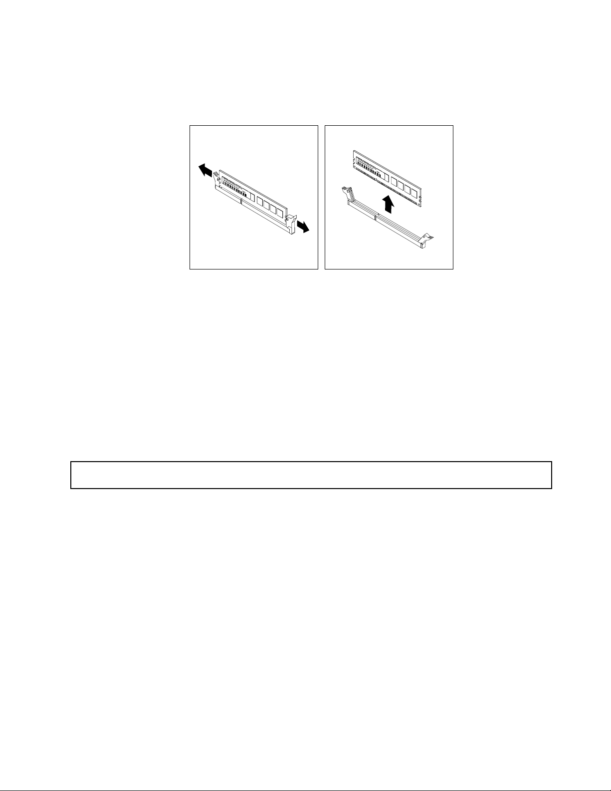
6.Locatetheappropriatememorymodulethatyouwanttoremoveandopentheretainingclipsonboth
endsofthememoryslot.Then,graspthememorymodulebyitsedgesandcarefullypullitstraight
uptoremoveitfromthememoryslot.
Figure14.Removingamemorymodule
7.Ifyouareinstructedtoreturntheoldmemorymodule,followallpackaginginstructionsanduseany
packagingmaterialsthataresuppliedtoyouforshipping.
Whattodonext:
•Toworkwithanotherpieceofhardware,gototheappropriatesection.
•Tocompletetheremovalprocedure,goto“Completingthepartsreplacement”onpage79
.
Installingorremovingthetertiaryharddiskdrive
Thistopicprovidesinstructionsonhowtoinstallorremovethetertiaryharddiskdrive.
Installingthetertiaryharddiskdrive
Attention:Donotopenyourserverorattemptanyrepairbeforereadingandunderstanding“Safetyinformation”
onpageiiiand“Guidelines”onpage35.
Youcaninstallatertiary3.5-inchharddiskdriveintothesecondaryopticaldrivebayofyourserver.
Thistopicprovidesinstructionsonhowtoinstallthetertiaryharddiskdrive.
Toinstallthetertiaryharddiskdrive,dothefollowing:
1.Removeallmediafromthedrivesandturnoffallattacheddevicesandtheserver.Then,disconnectall
powercordsfromelectricaloutletsanddisconnectallcablesthatareconnectedtotheserver.
2.Removetheservercover.See“Removingtheservercover”onpage37.
3.Removethefrontbezel.See“Removingandreinstallingthefrontbezel”onpage38.
Chapter6.Installing,removing,orreplacinghardware45
Page 58
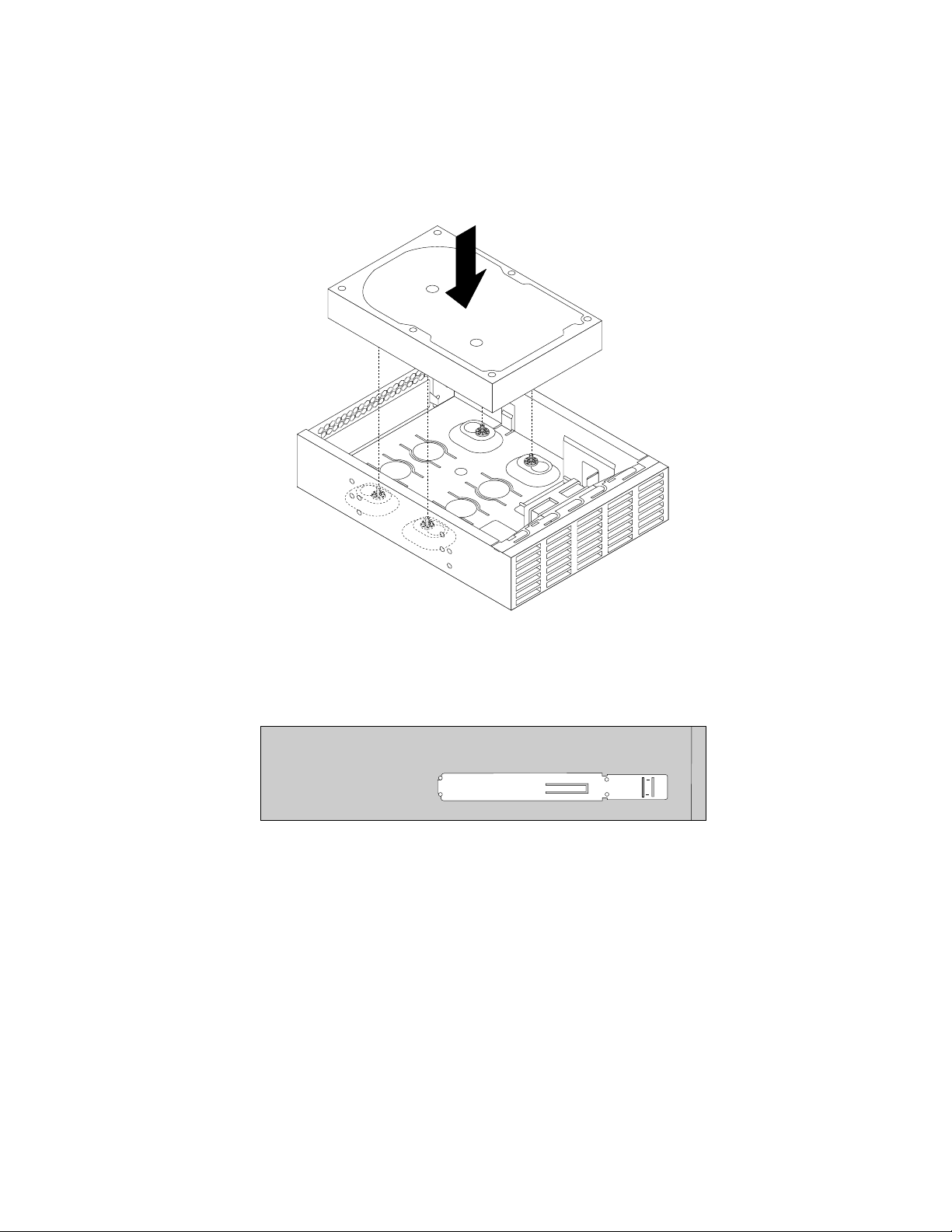
4.Installtheharddiskdriveintothe5.25-inchto3.5-inchdriveconversionbracket.Then,installthefour
screwstosecuretheharddiskdriveinthebracket.
Note:Youcanobtaina5.25-inchto3.5-inchdriveconversionbracketfromalocalcomputerretailer
orbycontactingtheCustomerSupportCenter.
Figure15.Installingtheharddiskdriveintothedriveconversionbracket
5.Installtheretaineronthesideofthebracket.
Figure16.Installingtheretaineronthesideofthebracket
6.Ifthereisametalstaticshieldinstalledinthesecondaryopticaldrivebay,removethemetalstaticshield.
46ThinkServerTS140UserGuide
Page 59

7.Slidethedriveconversionbracketintothesecondaryopticaldrivebayfromthefrontoftheserver
untilthebracketsnapsintoposition.
Figure17.Installingthedriveconversionbracketintothesecondaryopticaldrivebay
8.Connectthesignalcableandthepowercabletotherearofthenewharddiskdrive.
Figure18.Connectingcablestotheharddiskdrive
Chapter6.Installing,removing,orreplacinghardware47
Page 60

9.Connectthecableofthefanforthetertiaryharddiskdrivetooneoftheavailableconnectors1ofthe
fanpowerconvertercable.Then,connecttheconnector2totheharddiskdrivefanconnectoronthe
systemboard.See“Locatingpartsonthesystemboard”onpage15.
Figure19.Connectingthecableofthefanforthetertiaryharddiskdrive
10.Removetheplasticpanelthatprotectsthesecondaryopticaldrivebayfromthefrontbezel.
11.Reinstallthefrontbezel.See“Removingandreinstallingthefrontbezel”onpage38.
Whattodonext:
•Toworkwithanotherpieceofhardware,gototheappropriatesection.
•Tocompletetheinstallation,goto“Completingthepartsreplacement”onpage79
.
Removingthetertiaryharddiskdrive
Attention:Donotopenyourserverorattemptanyrepairbeforereadingandunderstanding“Safetyinformation”
onpageiiiand“Guidelines”onpage35.
Thistopicprovidesinstructionsonhowtoremovethetertiary3.5-inchharddiskdrive.
Toremovethetertiary3.5-inchharddiskdrive,dothefollowing:
1.Removeallmediafromthedrivesandturnoffallattacheddevicesandtheserver.Then,disconnectall
powercordsfromelectricaloutletsanddisconnectallcablesthatareconnectedtotheserver.
2.Removetheservercover.See“Removingtheservercover”onpage37.
3.Removethefrontbezel.See“Removingandreinstallingthefrontbezel”onpage38.
4.Disconnectthesignalcableandthepowercablefromtherearofthetertiaryharddiskdrive.
5.Disconnectthecableofthefanforthetertiaryharddiskdrivefromthefanpowerconvertercable.
48ThinkServerTS140UserGuide
Page 61
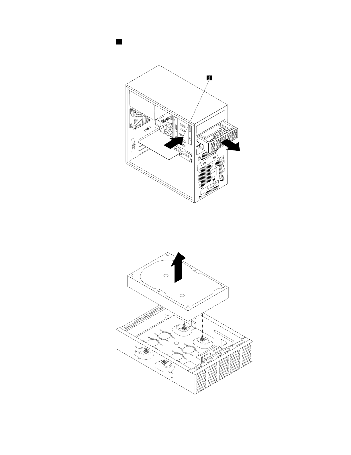
6.Pressthereleasebutton1andslidethedriveconversionbracketwiththetertiaryharddiskdrive
outofthefrontoftheserver.
Figure20.Removingthedriveconversionbracket
7.Removethefourscrewsthatsecuretheharddiskdrive.Then,removetheharddiskdriveoutofthe
driveconversionbracket.
Figure21.Removingtheharddiskdriveoutofthedriveconversionbracket
Chapter6.Installing,removing,orreplacinghardware49
Page 62
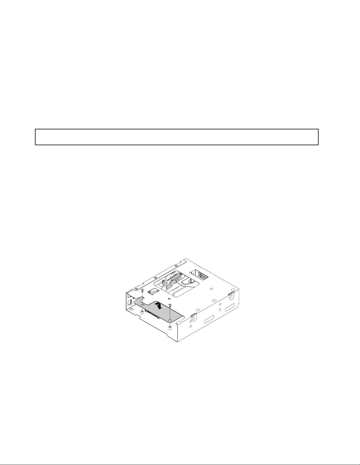
8.Toinstallanewtertiaryharddiskdrive,see“Installingthetertiaryharddiskdrive”onpage45.
Whattodonext:
•Toworkwithanotherpieceofhardware,gototheappropriatesection.
•Tocompletetheremovalprocedure,goto“Completingthepartsreplacement”onpage79
.
Installingorremovingtheslimopticaldriveandthefourthharddiskdrive
Thissectionprovidesinstructionsonhowtoinstallorremovetheslimopticaldriveandthefourthhard
diskdrive.
Installingtheslimopticaldriveandthefourthharddiskdrive
Attention:Donotopenyourserverorattemptanyrepairbeforereadingandunderstanding“Safetyinformation”
onpageiii
Youcaninstallaslimopticaldriveandafourthharddiskdriveintotheopticaldrivebayofyourserver.
Thistopicprovidesinstructionsonhowtoinstalltheslimopticaldriveandthefourthharddiskdriveintothe
opticaldrivebay.
Toinstalltheslimopticaldriveandthefourthharddiskdrive,dothefollowing:
1.Removeallmediafromthedrivesandturnoffallattacheddevicesandtheserver.Then,disconnectall
2.Removetheservercover.See“Removingtheservercover”onpage37.
3.Removethefrontbezel.See“Removingandreinstallingthefrontbezel”onpage38.
4.Installtheslimopticaldriveconversionboardintothecagefortheslimopticaldriveandthefourthhard
and“Guidelines”onpage35.
powercordsfromelectricaloutletsanddisconnectallcablesthatareconnectedtotheserver.
diskdrive.Then,installthetwoscrewstosecuretheslimopticaldriveconversionboard.
Figure22.Installingtheslimopticaldriveconversionboard
50ThinkServerTS140UserGuide
Page 63
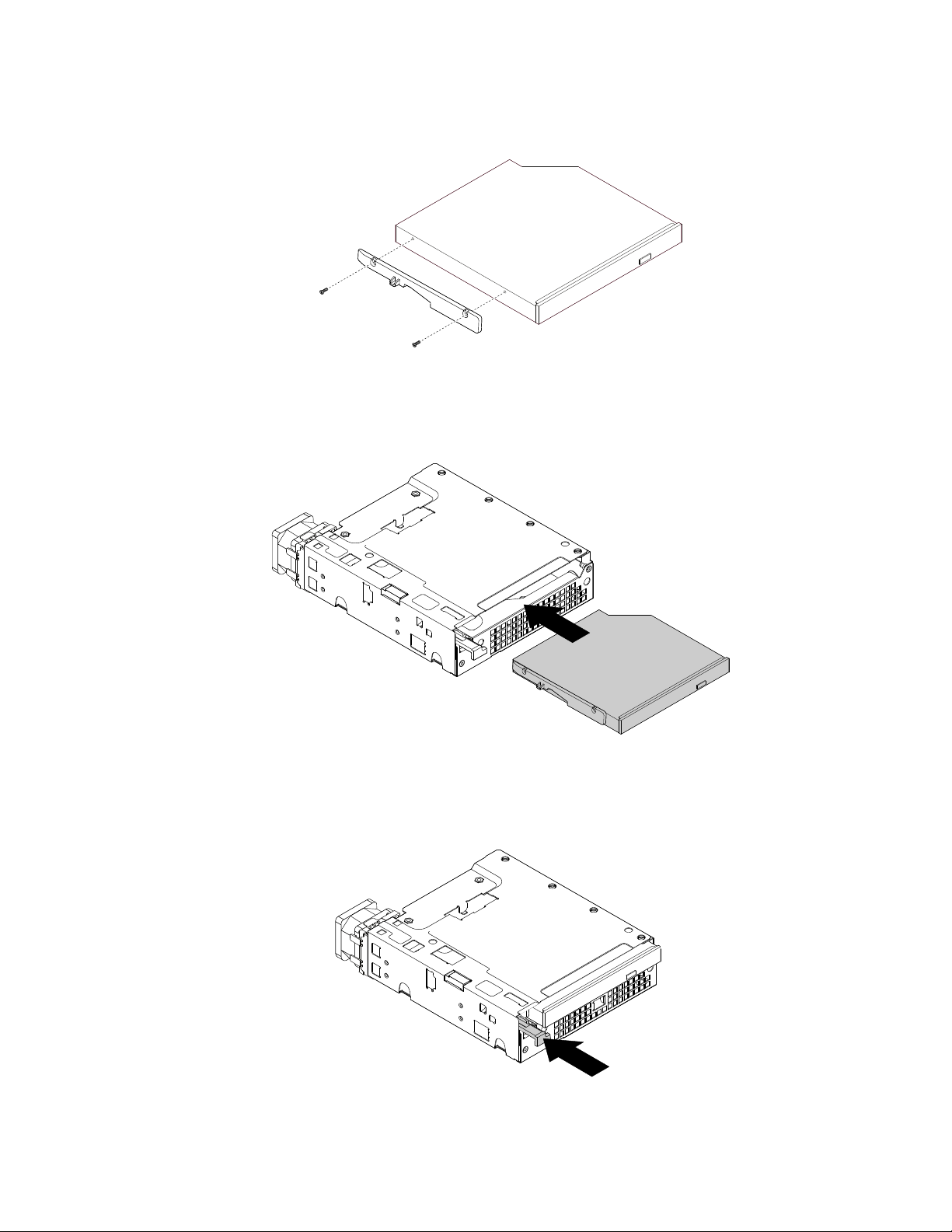
5.Installthetwoscrewstosecuretheslimopticaldriveretainertothesideoftheslimopticaldrive.
Figure23.Installingtheslimopticaldriveretainer
6.Installtheslimopticaldrivewiththeretainerintothecage.
Figure24.Installingtheslimopticaldriveintothecage
7.Pressthetabatthefrontofthecageuntilyouhearaclick.Theslimopticaldriveissecuredinplace.
Figure25.Securingtheslimopticaldriveinthecage
Chapter6.Installing,removing,orreplacinghardware51
Page 64

8.Slidetheharddiskdriveintothecagefromtherearofthecage.
Figure26.Slidingtheharddiskdriveintothecage
9.Installthefourscrewstosecuretheharddiskdriveinthecage.
Figure27.Installingthescrewstosecuretheharddiskdriveinthecage
10.Installthecageretaineronthesideofthecage.
Figure28.Installingthecageretainer
52ThinkServerTS140UserGuide
Page 65
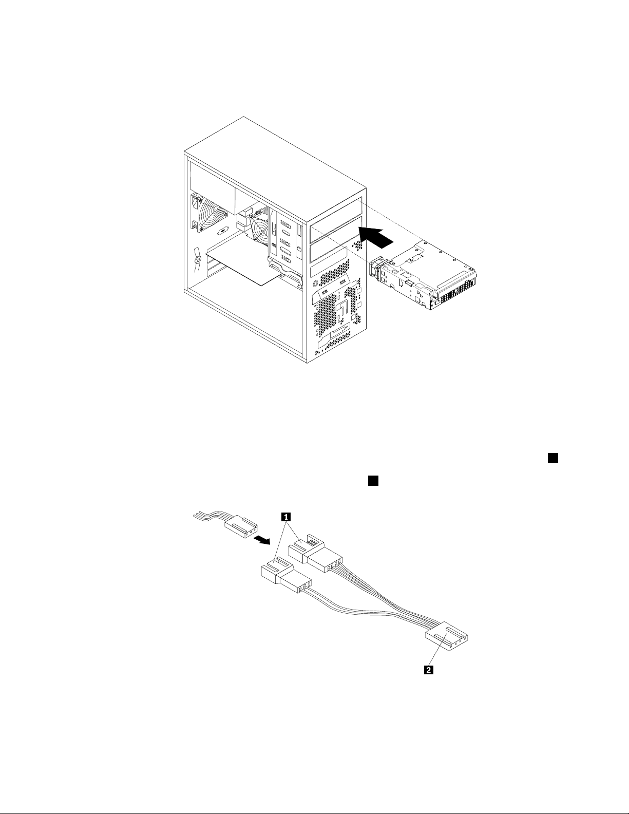
11.Slidethecagewiththeslimopticaldriveandtheharddiskdriveintotheopticaldrivebayfromthefront
oftheserveruntilthecagesnapsintoposition.
Figure29.Slidingthecageintotheopticaldrivebay
12.Connectthesignalcablesandthepowercablestotheslimopticaldriveandtheharddiskdrive.
13.Connectthecableofthefanforthefourthharddiskdrivetotheharddiskdrivefanconnectoronthe
systemboard.See“Locatingpartsonthesystemboard”onpage15.
Note:Ifyourserverhasatertiaryharddiskdriveinstalled,thefanpowerconvertercableconnector
connectedtotheharddiskdrivefanconnectoronthesystemboard.Connectthecableofthefanfor
thefourthharddiskdrivetooneoftheavailableconnectors1ofthefanpowerconvertercable.
2is
Figure30.Connectingthecableofthefanforthefourthharddiskdrive
14.Installtheplasticbezelforthecageontothefrontbezel.
15.Reinstallthefrontbezel.See“Removingandreinstallingthefrontbezel”onpage38.
Chapter6.Installing,removing,orreplacinghardware53
Page 66

Whattodonext:
•Toworkwithanotherpieceofhardware,gototheappropriatesection.
•Tocompletetheinstallation,goto“Completingthepartsreplacement”onpage79.
Removingtheslimopticaldriveandthefourthharddiskdrive
Attention:Donotopenyourserverorattemptanyrepairbeforereadingandunderstanding“Safetyinformation”
onpageiiiand“Guidelines”onpage35.
Thistopicprovidesinstructionsonhowtoremovetheslimopticaldriveandthefourthharddiskdrive.
Toremovetheslimopticaldriveandthefourthharddiskdrive,dothefollowing:
1.Removeallmediafromthedrivesandturnoffallattacheddevicesandtheserver.Then,disconnectall
powercordsfromelectricaloutletsanddisconnectallcablesthatareconnectedtotheserver.
2.Removetheservercover.See“Removingtheservercover”onpage37.
3.Removethefrontbezel.See“Removingandreinstallingthefrontbezel”onpage38.
4.Disconnectthesignalcablesandthepowercablesfromtheslimopticaldriveandthefourthhard
diskdrive.
5.Disconnectthecableofthefanforthefourthharddiskdrivefromtheharddiskdrivefanconnectoron
thesystemboard.See“Locatingpartsonthesystemboard”onpage15.
Note:Ifyourserverhasatertiaryharddiskdriveinstalled,disconnectthecableofthefanforthefourth
harddiskdrivefromthefanpowerconvertercable.
6.Pressthereleasebutton1andslidethecagewiththeslimopticaldriveandthefourthharddiskdrive
outofthefrontoftheserver.
Figure31.Removingthecagewiththeslimopticaldriveandthefourthharddiskdrive
54ThinkServerTS140UserGuide
Page 67

7.Pressthereleasebutton1toejectthetab2thatsecurestheslimopticaldrive.Then,slidetheslim
opticaldriveoutofthefrontofthecage.
Figure32.Removingtheslimopticaldrivefromthecage
8.Removetheslimopticaldriveretainerbyremovingthetwoscrewsthatsecuretheretainer.
Figure33.Removingtheslimopticaldriveretainer
9.Removethefourscrewsthatsecuretheharddiskdrive.Then,slidetheharddiskdriveoutofthe
rearofthecage.
Chapter6.Installing,removing,orreplacinghardware55
Page 68

Figure34.Removingtheharddiskdrivefromthecage
10.Toinstallanewslimopticaldriveandanewfourthharddiskdrive,see“Installingtheslimoptical
driveandthefourthharddiskdrive”onpage50.
Whattodonext:
•Toworkwithanotherpieceofhardware,gototheappropriatesection.
•Tocompletetheremovalprocedure,goto“Completingthepartsreplacement”onpage79.
InstallingorreplacingaPCIcard
Attention:Donotopenyourserverorattemptanyrepairbeforereadingandunderstanding“Safetyinformation”
onpageiiiand“Guidelines”onpage35.
ThissectionprovidesinstructionsonhowtoinstallorreplaceaPCIcard.
YourserverhasonestandardPCIcardslot,onePCIExpressx1cardslot,onePCIExpressx4cardslot,and
onePCIExpressx16cardslot.
ToinstallorreplaceaPCIcard,dothefollowing:
1.Removeallmediafromthedrivesandturnoffallattacheddevicesandtheserver.Then,disconnectall
powercordsfromelectricaloutletsanddisconnectallcablesthatareconnectedtotheserver.
2.Removetheservercover.See“Removingtheservercover”onpage37.
56ThinkServerTS140UserGuide
Page 69
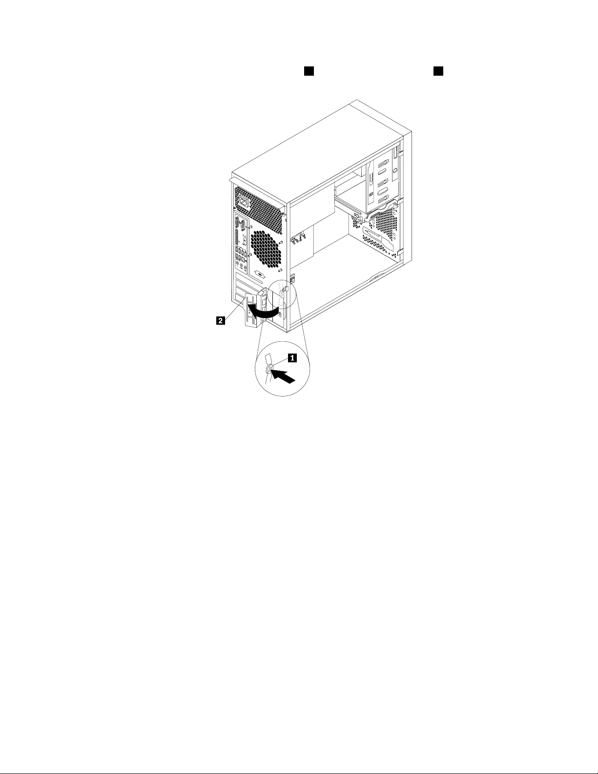
3.Attherearoftheserver,pressthereleasebutton1toopenthePCIcardlatch2.
Figure35.OpeningthePCIcardlatch
Chapter6.Installing,removing,orreplacinghardware57
Page 70

4.IfyouareinstallingaPCIcard,removetheappropriatemetalslotcover.IfyouarereplacinganoldPCI
card,grasptheoldcardthatiscurrentlyinstalledandgentlypullitoutoftheslot.
Notes:
a.ThePCIcardtstightlyintothecardslot.Ifnecessary,alternatemovingeachsideofthecarda
smallandequalamountuntilitiscompletelyremovedfromthecardslot.
b.IfthePCIcardisheldinplacebyaretainingclip,openthecardretainingclip1asshown.Graspthe
PCIcardandgentlypullitoutofthecardslot.
Figure36.OpeningthePCIcardretainingclip
Figure37.RemovingaPCIcard
5.RemovethenewPCIcardfromitsstatic-protectivepackage.
6.InstallthenewPCIcardintotheappropriateslotonthesystemboard.See“Locatingpartsonthe
systemboard”onpage15.
Note:IfyouareinstallingaPCIExpressx16card,makesurethememoryslotretainingclipsareclosed
beforeyouinstallthePCIExpressx16card.
58ThinkServerTS140UserGuide
Page 71

7.PivotthePCIcardlatchtotheclosedpositiontosecurethePCIcard.
Figure38.InstallingaPCIcard
Note:IfyouareinstallingaPCIcardintoaslotwiththeretainingclip,closethecardretainingclip
asshown.
Figure39.ClosingthePCIcardretainingclip
Chapter6.Installing,removing,orreplacinghardware59
Page 72

Whattodonext:
•Toworkwithanotherpieceofhardware,gototheappropriatesection.
•Tocompletetheinstallationorreplacement,goto“Completingthepartsreplacement”onpage79.
Installingorreplacingtheopticaldrive
Attention:Donotopenyourserverorattemptanyrepairbeforereadingandunderstanding“Safetyinformation”
onpageiii
Thissectionprovidesinstructionsonhowtoinstallorreplacetheopticaldrive.
Toinstallorreplaceanopticaldrive,dothefollowing:
1.Removeallmediafromthedrivesandturnoffallattacheddevicesandtheserver.Then,disconnectall
2.Removetheservercover.See“Removingtheservercover”onpage37.
3.Removethefrontbezel.See“Removingandreinstallingthefrontbezel”onpage38.
4.Dependingonwhetheryouareinstallingorreplacinganopticaldrive,dooneofthefollowing:
and“Guidelines”onpage35.
powercordsfromelectricaloutletsanddisconnectallcablesthatareconnectedtotheserver.
•Ifyouareinstallingasecondaryopticaldrive,removetheplasticpanelinthefrontbezelforthe
drivebayyouwanttouse.Ifthereisametalstaticshieldinstalledinthedrivebay,removethe
metalstaticshield.
•Ifyouarereplacinganopticaldrive,disconnectthesignalcableandthepowercablefromthe
rearoftheopticaldrive,pressthebluereleasebutton
1andthenslidetheopticaldriveoutof
thefrontoftheserver.
Figure40.Removingtheopticaldrive
60ThinkServerTS140UserGuide
Page 73

5.Slidethenewopticaldrivewiththeopticaldriveretainer1installedintothedrivebayfromthefrontof
theserveruntiltheopticaldrivesnapsintoposition.
Figure41.Installingtheopticaldrive
6.Reinstallthefrontbezel.See“Removingandreinstallingthefrontbezel”onpage38.
7.ConnectoneendofthesignalcabletotheopticaldriveandtheotherendtoanavailableSATA
connectoronthesystemboard.See“Locatingpartsonthesystemboard”onpage15.Then,locatean
availableve-wirepowerconnectorandconnectittotheSATAdrive.
Figure42.ConnectingaSATAopticaldrive
Whattodonext:
•Toworkwithanotherpieceofhardware,gototheappropriatesection.
•Tocompletetheinstallationorreplacement,goto“Completingthepartsreplacement”onpage79
.
Installingorreplacingthesecondaryharddiskdrive
Attention:Donotopenyourserverorattemptanyrepairbeforereadingandunderstanding“Safetyinformation”
onpageiiiand“Guidelines”onpage35.
Chapter6.Installing,removing,orreplacinghardware61
Page 74
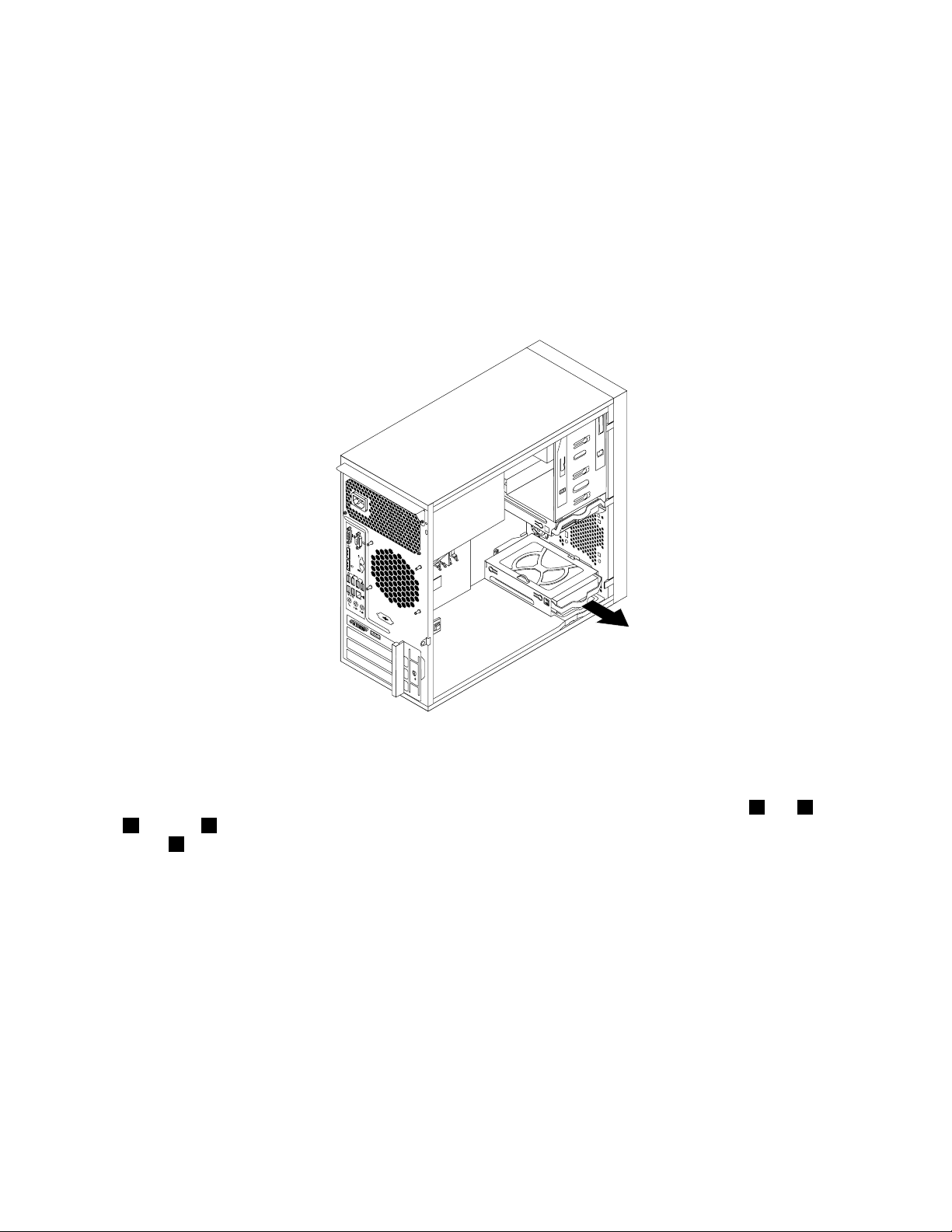
Toinstallorreplacethesecondaryharddiskdrive,dothefollowing:
1.Removeallmediafromthedrivesandturnoffallattacheddevicesandtheserver.Then,disconnectall
powercordsfromelectricaloutletsanddisconnectallcablesthatareconnectedtotheserver.
2.Removetheservercover.See“Removingtheservercover”onpage37.
3.Locatethesecondaryharddiskdrive.See“Locatingpartsonthesystemboard”onpage15and
“Internaldrives”onpage16
.
4.Ifyouarereplacingthesecondaryharddiskdrive,disconnectthesignalcableandthepowercable
fromtheharddiskdrive.
5.Pullthebluehandletoreleaseandremovetheharddiskdrivefromtheharddiskdrivecage.
Figure43.Removingthesecondaryharddiskdrive
6.Flexthesidesofthebluebrackettoremovetheharddiskdrivefromthebracket.
7.Toinstallthesecondaryharddiskdrive,exthesidesofthebracketproperlyandalignpin1,pin2,pin
3,andpin4onthebracketwiththecorrespondingholesintheharddiskdrive.Donottouchthecircuit
board5onthebottomoftheharddiskdrive.
62ThinkServerTS140UserGuide
Page 75
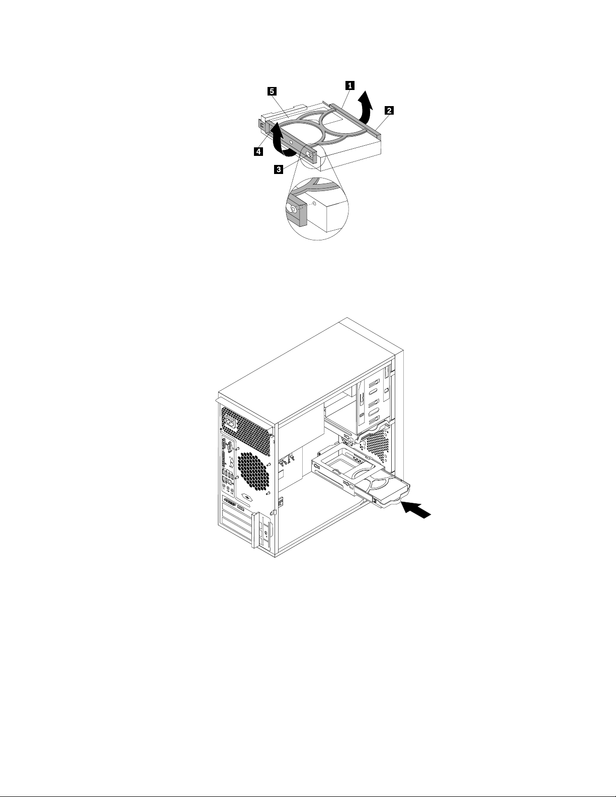
Figure44.Installingtheharddiskdriveintothebracket
8.Slidethenewharddiskdriveintotheharddiskdrivecageuntilitsnapsintoposition.
Figure45.Installingthesecondaryharddiskdrive
Chapter6.Installing,removing,orreplacinghardware63
Page 76

9.ConnectoneendofthesignalcabletotheharddiskdriveandtheotherendtoanavailableSATA
connectoronthesystemboard.See“Locatingpartsonthesystemboard”onpage15.Then,locatean
availableve-wirepowerconnectorandconnectittotheharddiskdrive.
Figure46.ConnectingaSATAharddiskdrive
Replacingtheprimaryharddiskdrive
Attention:Donotopenyourserverorattemptanyrepairbeforereadingandunderstanding“Safetyinformation”
onpageiiiand“Guidelines”onpage35.
Thissectionprovidesinstructionsonhowtoreplacetheprimaryharddiskdrive.
Toreplacetheprimaryharddiskdrive,dothefollowing:
1.Removeallmediafromthedrivesandturnoffallattacheddevicesandtheserver.Then,disconnectall
powercordsfromelectricaloutletsanddisconnectallcablesthatareconnectedtotheserver.
2.Removetheservercover.See“Removingtheservercover”onpage37.
3.Locatetheprimaryharddiskdrive.See“Locatingpartsonthesystemboard”onpage15.
4.Disconnectthesignalcableandthepowercablefromtherearoftheharddiskdrive.
64ThinkServerTS140UserGuide
Page 77
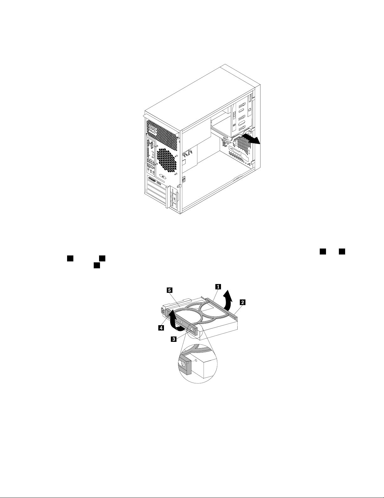
5.Pullthebluehandletoreleaseandremovetheharddiskdrivefromthedrivecage.
Figure47.Removingtheprimaryharddiskdrive
6.Flexthesidesofthebluebrackettoremovetheharddiskdrivefromthebracket.
7.Toinstallanewharddiskdriveintothebluebracket,exthesidesofthebracketandalignpin1,pin2,
pin3,andpin4onthebracketwiththecorrespondingholesintheharddiskdrive.Donottouchthe
circuitboard5onthebottomoftheharddiskdrive.
Figure48.Installingtheharddiskdriveintothebracket
8.Slidethenewharddiskdriveintothedrivecageuntilitsnapsintoposition.
Chapter6.Installing,removing,orreplacinghardware65
Page 78
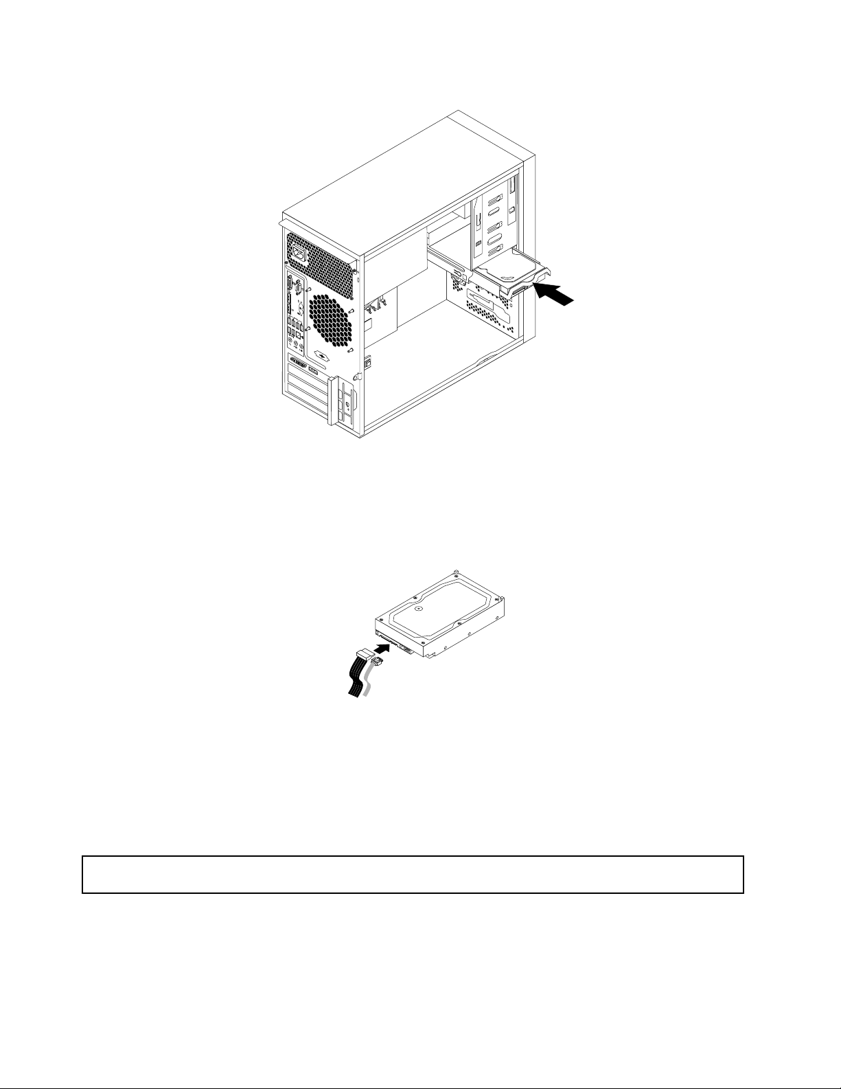
Figure49.Installingtheprimaryharddiskdrive
9.ConnectoneendofthesignalcabletotheharddiskdriveandtheotherendtoanavailableSATA
connectoronthesystemboard.See“Locatingpartsonthesystemboard”onpage15.Then,locatean
availableve-wirepowerconnectorandconnectittotheharddiskdrive.
Figure50.ConnectingaSATAharddiskdrive
Whattodonext:
•Toworkwithanotherpieceofhardware,gototheappropriatesection.
•Tocompletethereplacement,goto“Completingthepartsreplacement”onpage79
.
Replacingthepowersupplyassembly
Attention:Donotopenyourserverorattemptanyrepairbeforereadingandunderstanding“Safetyinformation”
onpageiii
and“Guidelines”onpage35.
Thissectionprovidesinstructionsonhowtoreplacethepowersupplyassembly.
Althoughtherearenomovingpartsinyourserverafterthepowercordhasbeendisconnected,thefollowing
warningsarerequiredforyoursafetyandproperUnderwritersLaboratories(UL)certication.
66ThinkServerTS140UserGuide
Page 79
DANGER
Hazardousmovingparts.Keepngersandotherbodypartsaway.
CAUTION:
Neverremovethecoveronapowersupplyoranypartthathasthefollowinglabelattached.
Hazardousvoltage,current,andenergylevelsarepresentinsideanycomponentthathasthislabel
attached.Therearenoserviceablepartsinsidethesecomponents.Ifyoususpectaproblemwith
oneoftheseparts,contactaservicetechnician.
Toreplacethepowersupplyassembly,dothefollowing:
1.Removeallmediafromthedrivesandturnoffallattacheddevicesandtheserver.Then,disconnectall
powercordsfromelectricaloutletsanddisconnectallcablesthatareconnectedtotheserver.
2.Removetheservercover.See“Removingtheservercover”onpage37.
3.Laytheserveronitssideanddisconnectthepowersupplyassemblycablesfromthesystemboardand
alldrives.See“Locatingpartsonthesystemboard”onpage15.
Chapter6.Installing,removing,orreplacinghardware67
Page 80

4.Removethefourscrewsattherearofthechassisthatsecurethepowersupplyassembly.
Figure51.Removingthescrewsthatsecurethepowersupplyassembly
5.Slidethepowersupplyassemblyalittlebitforwardandthenremoveitfromthechassis.
Figure52.Removingthepowersupplyassembly
6.Ensurethatthenewpowersupplyassemblyisthecorrectreplacement.
7.Installthenewpowersupplyassemblyintothechassissothatthescrewholesinthepowersupply
assemblyalignwiththoseinthechassis.
8.Installandtightenthefourscrewstosecurethepowersupplyassembly.
Note:UseonlyscrewsprovidedbyLenovo.
9.Reconnectthepowersupplyassemblycablestothesystemboardandeachofthedrives.
10.Securethepowersupplyassemblycableswiththecableclipsandtiesinthechassis.
68ThinkServerTS140UserGuide
Page 81

Whattodonext:
•Toworkwithanotherpieceofhardware,gototheappropriatesection.
•Tocompletethereplacement,goto“Completingthepartsreplacement”onpage79.
Replacingtheheatsinkandfanassembly
Attention:Donotopenyourserverorattemptanyrepairbeforereadingandunderstanding“Safetyinformation”
onpageiii
Thissectionprovidesinstructionsonhowtoreplacetheheatsinkandfanassembly.
CAUTION:
Turnofftheserverandwaitthreetoveminutestolettheservercoolbeforeremovingtheserver
cover.
Toreplacetheheatsinkandfanassembly,dothefollowing:
1.Removeallmediafromthedrivesandturnoffallattacheddevicesandtheserver.Then,disconnectall
2.Removetheservercover.See“Removingtheservercover”onpage37.
3.Laytheserveronitssideforeasieraccesstothesystemboard.
4.Locatetheheatsinkandfanassembly.See“Locatingpartsonthesystemboard”onpage15.
5.Disconnecttheheatsinkandfanassemblycablefromthemicroprocessorfanconnectoronthesystem
and“Guidelines”onpage35.
powercordsfromelectricaloutletsanddisconnectallcablesthatareconnectedtotheserver.
board.See“Locatingpartsonthesystemboard”onpage15.
Chapter6.Installing,removing,orreplacinghardware69
Page 82

6.Followthissequencetoremovethefourscrewsthatsecuretheheatsinkandfanassemblytothe
systemboard:
a.Partiallyremovescrew1,thenfullyremovescrew2,andthenfullyremovescrew1.
b.Partiallyremovescrew3,thenfullyremovescrew4,andthenfullyremovescrew3.
Note:Carefullyremovethefourscrewsfromthesystemboardtoavoidanypossibledamagetothe
systemboard.Thefourscrewscannotberemovedfromtheheatsinkandfanassembly.
Figure53.Removingtheheatsinkandfanassembly
7.Liftthefailingheatsinkandfanassemblyoffthesystemboard.
Notes:
a.Youmighthavetogentlytwisttheheatsinkandfanassemblytofreeitfromthemicroprocessor.
b.Whilehandlingtheheatsinkandfanassembly,donottouchthethermalgreaseonthebottomofit.
8.Placethenewheatsinkandfanassemblyonthesystemboardsothatthefourscrewsontheheatsink
andfanassemblyarealignedwiththecorrespondingholesonthesystemboard.Makesurethatyou
properlyplacetheheatsinkandfanassemblysothatyoucaneasilyconnecttheheatsinkandfan
assemblycabletothemicroprocessorfanconnectoronthesystemboard.
9.Followthissequencetoinstallthefourscrewstosecurethenewheatsinkandfanassembly.SeeFigure
53“Removingtheheatsinkandfanassembly”onpage70.
a.Partiallytightenscrew1,thenfullytightenscrew2,andthenfullytightenscrew1.
b.Partiallytightenscrew3,thenfullytightenscrew4,andthenfullytightenscrew3.
Note:Donotover-tightenthescrews.
10.Connecttheheatsinkandfanassemblycabletothemicroprocessorfanconnectoronthesystem
board.See“Locatingpartsonthesystemboard”onpage15.
Whattodonext:
•Toworkwithanotherpieceofhardware,gototheappropriatesection.
70ThinkServerTS140UserGuide
Page 83

•Tocompletethereplacement,goto“Completingthepartsreplacement”onpage79.
ReplacingthefrontaudioandUSBassembly
Attention:Donotopenyourserverorattemptanyrepairbeforereadingandunderstanding“Safetyinformation”
onpageiii
ThissectionprovidesinstructionsonhowtoreplacethefrontaudioandUSBassembly.
ToreplacethefrontaudioandUSBassembly,dothefollowing:
1.Removeallmediafromthedrivesandturnoffallattacheddevicesandtheserver.Then,disconnectall
2.Removetheservercover.See“Removingtheservercover”onpage37.
3.Removethefrontbezel.See“Removingandreinstallingthefrontbezel”onpage38.
4.DisconnectthefrontaudioandUSBassemblycablefromthesystemboard.See“Locations”on
5.NotethefrontaudioandUSBassemblycableroutingandremovethescrewthatsecuresthefrontaudio
and“Guidelines”onpage35.
powercordsfromelectricaloutletsanddisconnectallcablesthatareconnectedtotheserver.
page11.
andUSBassembly.Then,removethefrontaudioandUSBassemblyfromthechassis.
Figure54.RemovingthefrontaudioandUSBassembly
6.RoutethenewfrontaudioandUSBassemblythroughtheholeinthechassis.
7.PositionthenewfrontaudioandUSBassemblytothechassissothatthescrewholeinthenewfront
audioandUSBassemblyisalignedwiththecorrespondingholeinthechassis.
8.InstallthescrewtosecurethenewfrontaudioandUSBassemblyinplace.
9.ConnectthenewfrontaudioandUSBassemblycablestothesystemboard.See“Locations”on
page11.
10.Reinstallthefrontbezel.See“Removingandreinstallingthefrontbezel”onpage38.
Chapter6.Installing,removing,orreplacinghardware71
Page 84

Whattodonext:
•Toworkwithanotherpieceofhardware,gototheappropriatesection.
•Tocompletethereplacement,goto“Completingthepartsreplacement”onpage79.
Replacingthefrontfanassembly
Attention:Donotopenyourserverorattemptanyrepairbeforereadingandunderstanding“Safetyinformation”
onpageiii
Dependingonthemodeltype,yourservermighthaveafrontfanassemblyinstalled.Thissectionprovides
instructionsonhowtoreplacethefrontfanassembly.
Toreplacethefrontfanassembly,dothefollowing:
1.Removeallmediafromthedrivesandturnoffallattacheddevicesandtheserver.Then,disconnectall
2.Removetheservercover.See“Removingtheservercover”onpage37.
3.Removethefrontbezel.See“Removingandreinstallingthefrontbezel”onpage38.
4.Disconnectthefrontfanassemblycablefromthepowerfanconnectoronthesystemboard.See
5.Thefrontfanassemblyisattachedtothechassisbyfourrubbermounts.Removethefrontfanassembly
and“Guidelines”onpage35.
powercordsfromelectricaloutletsanddisconnectallcablesthatareconnectedtotheserver.
“Locatingpartsonthesystemboard”onpage15.
bybreakingorcuttingtherubbermountsandgentlypullingthefrontfanassemblyoutofthechassis.
Note:Thenewfrontfanassemblywillhavefournewrubbermountsattached.
Figure55.Removingthefrontfanassembly
6.Installthenewfrontfanassemblybyaligningthenewrubbermountswiththecorrespondingholesin
thechassisandpushtherubbermountsthroughtheholes.
72ThinkServerTS140UserGuide
Page 85

7.Carefullypullonthetipsoftherubbermountsuntilthefrontfanassemblyissecuredinplace.
Figure56.Installingthefrontfanassembly
8.Connectthenewfrontfanassemblycabletothepowerfanconnectoronthesystemboard.See
“Locatingpartsonthesystemboard”onpage15.
Whattodonext:
•Toworkwithanotherpieceofhardware,gototheappropriatesection.
•Tocompletethereplacement,goto“Completingthepartsreplacement”onpage79
.
Replacingtherearfanassembly
Attention:Donotopenyourserverorattemptanyrepairbeforereadingandunderstanding“Safetyinformation”
onpageiiiand“Guidelines”onpage35.
Thissectionprovidesinstructionsonhowtoreplacetherearfanassembly.
Toreplacetherearfanassembly,dothefollowing:
1.Removeallmediafromthedrivesandturnoffallattacheddevicesandtheserver.Then,disconnectall
powercordsfromelectricaloutletsanddisconnectallcablesthatareconnectedtotheserver.
2.Removetheservercover.See“Removingtheservercover”onpage37.
3.Locatetherearfanassembly.See“Internalcomponents”onpage16.
4.Disconnecttherearfanassemblycablefromthesystemfanconnectoronthesystemboard.See
“Locatingpartsonthesystemboard”onpage15.
Chapter6.Installing,removing,orreplacinghardware73
Page 86

5.Therearfanassemblyisattachedtothechassisbyfourrubbermounts.Removetherearfanassembly
bycuttingtherubbermountsandgentlypullingtherearfanassemblyoutofthechassis.
Note:Thenewrearfanassemblywillhavefournewrubbermountsattached.
Figure57.Removingtherearfanassembly
6.Installthenewrearfanassemblybyaligningthenewrubbermountswiththecorrespondingholesinthe
chassisandpushtherubbermountsthroughtheholes.
74ThinkServerTS140UserGuide
Page 87

7.Carefullypullonthetipsoftherubbermountsuntilthenewrearfanassemblyissecuredinplace.
Figure58.Installingtherearfanassembly
8.Connectthenewrearfanassemblycabletothesystemfanconnectoronthesystemboard.See
“Locatingpartsonthesystemboard”onpage15.
Whattodonext:
•Toworkwithanotherpieceofhardware,gototheappropriatesection.
•Tocompletethereplacement,goto“Completingthepartsreplacement”onpage79.
Replacingthemicroprocessor
Attention:Donotopenyourserverorattemptanyrepairbeforereadingandunderstanding“Safetyinformation”
onpageiii
Thissectionprovidesinstructionsonhowtoreplacethemicroprocessor.
CAUTION:
Theheatsinkandmicroprocessormightbeveryhot.Turnoffthecomputerandwaitthreetove
minutestoletthecomputercoolbeforeremovingthecomputercover.
Toreplacethemicroprocessor,dothefollowing:
and“Guidelines”onpage35.
Chapter6.Installing,removing,orreplacinghardware75
Page 88
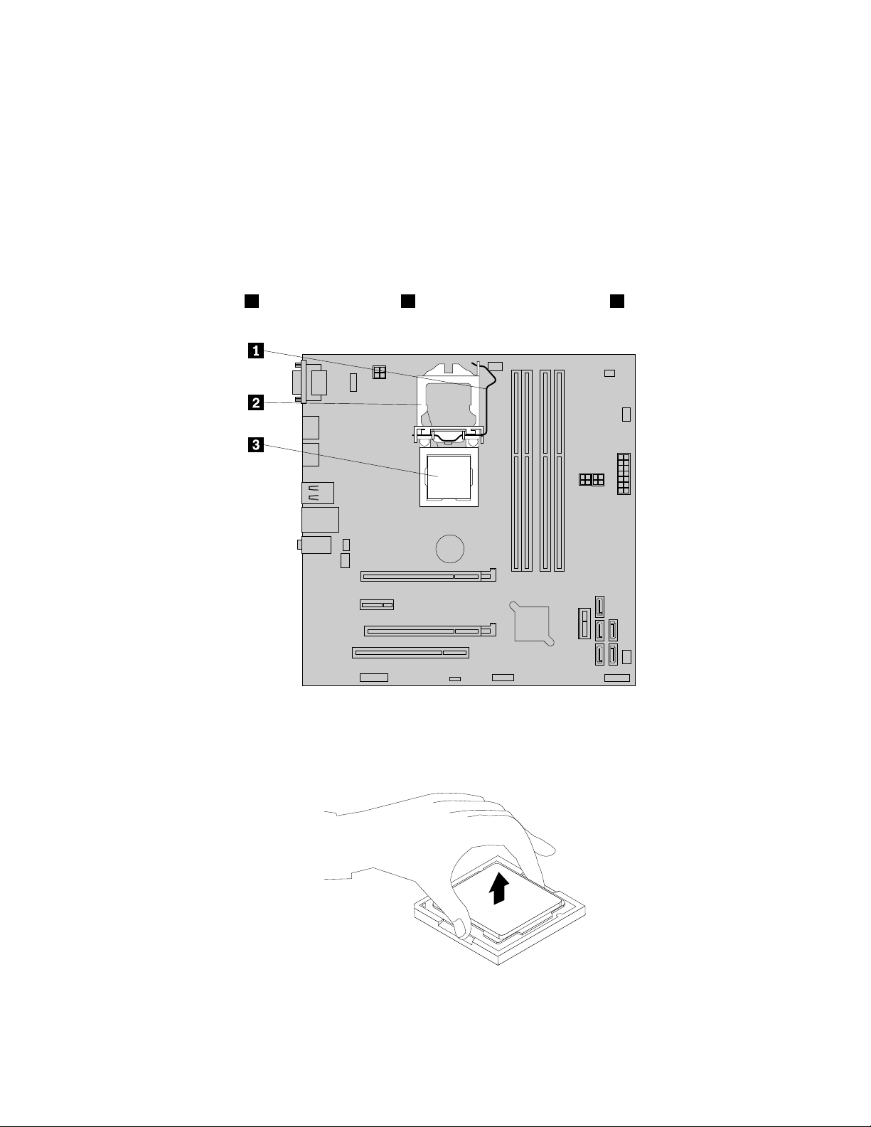
1.Removeallmediafromthedrivesandturnoffallattacheddevicesandthecomputer.Then,disconnect
allpowercordsfromelectricaloutletsanddisconnectallcablesthatareconnectedtothecomputer.
2.Removethecomputercover.See“Removingtheservercover”onpage37.
3.Laythecomputeronitssideforeasieraccesstothesystemboard.
4.Locatethesystemboardanddisconnectallcablesconnectedtothesystemboard.See“Locating
partsonthesystemboard”onpage15
.
5.Removetheheatsinkandfanassembly.See“Replacingtheheatsinkandfanassembly”onpage69.
Note:Placetheheatsinkandfanassemblyonitssidesothatthethermalgreaseonthebottomofit
doesnotgetincontactwithanything.
6.Liftthesmallhandle1andopentheretainer2toaccessthemicroprocessor3.
Figure59.Accessingthemicroprocessor
7.Liftthemicroprocessorstraightupandoutofthemicroprocessorsocket.
Figure60.Removingthemicroprocessor
76ThinkServerTS140UserGuide
Page 89

Notes:
a.Yourmicroprocessorandsocketmightlookdifferentfromtheoneillustrated.
b.Notetheorientationofthemicroprocessorinthesocket.Youcaneitherlookforthesmalltriangle1
ononecornerofthemicroprocessorornotetheorientationofthenotches2onthemicroprocessor.
Thisisimportantwheninstallingthenewmicroprocessoronthesystemboard.
c.Touchonlytheedgesofthemicroprocessor.Donottouchthegoldcontactsonthebottom.
d.Donotdropanythingontothemicroprocessorsocketwhileitisexposed.Thesocketpinsmustbe
keptascleanaspossible.
8.Makesurethatthesmallhandleisintheraisedpositionandthemicroprocessorretainerisfullyopen.
9.Removetheprotectivecoverthatprotectsthegoldcontactsofthenewmicroprocessor.
10.Holdthenewmicroprocessorbyitssidesandalignthesmalltriangleononecornerofthenew
microprocessorwiththecorrespondingsmalltriangleononecornerofthemicroprocessorsocket.
11.Lowerthenewmicroprocessorstraightdownintothemicroprocessorsocketonthesystemboard.
Figure61.Installingthemicroprocessor
12.Closethemicroprocessorretainerandlockitintopositionwiththesmallhandletosecurethenew
microprocessorinthesocket.
13.Reinstalltheheatsinkandfanassembly.See“Replacingtheheatsinkandfanassembly”onpage69.
Chapter6.Installing,removing,orreplacinghardware77
Page 90
14.Reconnectallcablesthatweredisconnectedfromthesystemboard.
Whattodonext:
•Toworkwithanotherpieceofhardware,gototheappropriatesection.
•Tocompletethereplacement,goto“Completingthepartsreplacement”onpage79.
Replacingthesystemboardbattery
Attention:Donotopenyourserverorattemptanyrepairbeforereadingandunderstanding“Safetyinformation”
onpageiii
Thissectionprovidesinstructionsonhowtoreplacethesystemboardbattery.
Yourserverhasaspecialtypeofmemorythatmaintainsthedate,time,andcongurationinformationfor
built-infeatures.Thesystemboardbatterykeepstheinformationactivewhenyouturnofftheserver.The
systemboardbatterynormallyrequiresnochargingormaintenancethroughoutitslife;however,nobattery
lastsforever.Ifthesystemboardbatteryfails,thedate,time,andcongurationinformation,including
passwords,arelostandanerrormessageisdisplayedwhenyouturnontheserver.
Dangerofexplosionifbatteryisincorrectlyreplaced.
and“Guidelines”onpage35.
DANGER
Whenreplacingthelithiumcoincellbattery,useonlythesameoranequivalenttypethatis
recommendedbythemanufacturer.Thebatterycontainslithiumandcanexplodeifnotproperly
used,handled,ordisposedof.
Donot:
•Throworimmerseintowater
•Heattomorethan100°C(212°F)
•Repairordisassemble
Disposeofthebatteryasrequiredbylocalordinancesorregulations.
ThefollowingstatementappliestousersinthestateofCalifornia,U.S.A.
CaliforniaPerchlorateInformation:
Productscontainingmanganesedioxidelithiumcoincellbatteriesmaycontainperchlorate.
PerchlorateMaterial-specialhandlingmayapply,
Seehttp://www.dtsc.ca.gov/hazardouswaste/perchlorate
Beforeyoubegin,printalltherelatedinstructionsorensurethatyoucanviewthePDFversiononanother
computerforreference.
Toreplacethesystemboardbattery,dothefollowing:
Note:Afteryoureplacethesystemboardbattery,youmustresetpasswords,resetsystemdateandtime,
andreconguretheserver.
1.Removeallmediafromthedrivesandturnoffallattacheddevicesandtheserver.Then,disconnectall
powercordsfromelectricaloutletsanddisconnectallcablesthatareconnectedtotheserver.
78ThinkServerTS140UserGuide
Page 91

2.Removetheservercover.See“Removingtheservercover”onpage37.
3.Locatethesystemboardbattery.See“Locations”onpage11.
4.Removetheoldsystemboardbattery.
Figure62.Removingtheoldsystemboardbattery
5.Installthenewsystemboardbattery.
Figure63.Installingthenewsystemboardbattery
6.Reinstallthecomputercoverandconnectthecables.See“Completingthepartsreplacement”on
page79.
Note:Whenthecomputeristurnedonforthersttimeafterthebatteryisreplaced,anerrormessage
mightbedisplayed.Thisisnormalafterreplacingthebattery.
7.Turnonthecomputerandallattacheddevices.
8.UsetheSetupUtilityprogramtosetthedate,time,andanypasswords.SeeChapter5“Conguring
theserver”onpage21.
9.Disposeofthefailingbatteryasrequiredbylocalordinancesorregulations.
Whattodonext:
•Toworkwithanotherpieceofhardware,gototheappropriatesection.
•Tocompletethereplacement,goto“Completingthepartsreplacement”onpage79
.
Completingthepartsreplacement
Aftercompletingtheinstallationorreplacementforallparts,youneedtoreinstalltheservercoverand
reconnectcables.
Toreinstalltheservercoverandreconnectcablestoyourserver,dothefollowing:
1.Makesurethatallcomponentshavebeenreassembledcorrectlyandthatnotoolsorloosescrewsare
leftinsideyourserver.See“Internalcomponents”onpage16forthelocationsofvariouscomponentsin
yourserver.
2.Ifyouhaveremovedthefrontbezel,reinstallit.See“Removingandreinstallingthefrontbezel”on
page38.
Chapter6.Installing,removing,orreplacinghardware79
Page 92

3.Makesurethatthecablesareroutedcorrectlybeforereinstallingtheservercover.Keepcablesclearof
thehingesandsidesoftheserverchassistoavoidinterferencewithreinstallingtheservercover.
4.Positiontheservercoveronthechassissothattherailguidesonthebottomoftheservercoverengage
therailsonthechassis.Then,slidethecovertothefrontoftheserveruntilitsnapsintoposition.
Figure64.Reinstallingtheservercover
5.Installthescrewstosecuretheservercover.
6.Locktheservercoverifyouhaveaservercoverlock.See“Integratedcablelock”onpage81or
“Padlock”onpage81.
7.Reconnecttheexternalcablesandpowercordstotheserver.See“Frontviewoftheserver”onpage
12and“Rearviewoftheserver”onpage13.
8.Dependingonthepartsyouinstalledorreplaced,youmightneedtoconrmtheupdatedinformationin
theSetupUtilityprogram.RefertoChapter5“Conguringtheserver”onpage21
Note:Inmostareasoftheworld,LenovorequiresthereturnofthedefectiveCustomerReplaceableUnit
(CRU).InformationaboutthiswillcomewiththeCRUorwillcomeafewdaysaftertheCRUarrives.
.
Connectingthecables
Attention:Topreventdamagetoequipment,connectthepowercordsaftercompletingtheparts
replacement.
Iftheservercablesandconnectorpanelhavecolor-codedconnections,matchthecolorofthecableend
withthecoloroftheconnector.Forexample,matchabluecableendwithabluepanelconnector,ared
cableendwitharedconnector,andsoon.See“Rearviewoftheserver”onpage13
I/Oconnectorsontherearoftheserver.
foranillustrationofthe
80ThinkServerTS140UserGuide
Page 93

Connectingexternaldevices
Ifyouinstallasupportedoptionaladapter,youcanattachexternaldevicestotheserver.
Toattachanexternaldevice,dothefollowing:
Note:Ifyouareattachinganexternaldevice,seethedocumentationthatcomeswiththedevicefor
informationaboutcabling.
1.ReadandunderstandtheSafety,Warranty,andSupportInformationathttp://www.lenovo.com/support,
and“Guidelines”onpage35.
2.Turnofftheserverandallattacheddevices.
3.Followtheinstructionsthatcomewiththedevicetoprepareitforinstallationandtoconnectitto
theserver.
Updatingtheserverconguration
Whenyoustarttheserverforthersttimeafteryouinstallorremoveaninternaloptionorexternaldevice,
youmightreceiveamessagesayingthatthecongurationhaschanged.TheSetupUtilityprogramstarts
automaticallysothatyoucansavethenewcongurationsettings.
Someoptionshavedevicedriversthatyoumustinstall.Forinformationaboutinstallingdevicedrivers,see
thedocumentationthatcomeswitheachoption.
Youcanobtaindevicedriversforoperatingsystemsthatarenotpreinstalledat
http://www.lenovo.com/support.Installationinstructionsareprovidedinreadmeleswiththedevice
driverles.
Installingsecurityfeatures
Thereareseveralsecurityoptionsavailabletohelpyoupreventhardwaretheftandunauthorizedaccessto
yourserver.Inadditiontophysicallocks,youcanalsopreventunauthorizeduseofyourserverbyasoftware
lockthatlocksthekeyboarduntilacorrectpasswordistypedin.
Note:Makesurethatanysecuritycablesyouinstalleddonotinterferewithotherservercables.
Integratedcablelock
Anintegratedcablelock,sometimesreferredtoastheKensingtonlock,canbeusedtosecureyourserverto
adesk,table,orothernon-permanentxture.Thecablelockattachestotheintegratedcablelockslotatthe
rearofyourserverandisoperatedwithakey.Thecablelockalsolocksthebuttonsusedtoremovethe
servercover.Thisisthesametypeoflockusedwithmanynotebookcomputers.Youcanorderanintegrated
cablelockdirectlyfromLenovobysearchingforKensingtonat:
http://www.lenovo.com/support
Padlock
Yourserverisequippedwithapadlockloopsothatthecovercannotberemovedwhenapadlockisinstalled.
Passwordprotection
Todeterunauthorizeduseofyourserver,youcanusetheSetupUtilityprogramtosetapassword.When
youturnonyourserver,youarepromptedtotypethepassword.Theservercannotbeuseduntilavalid
passwordistypedin.RefertoChapter5“Conguringtheserver”onpage21
formoreinformation.
Chapter6.Installing,removing,orreplacinghardware81
Page 94

82ThinkServerTS140UserGuide
Page 95

Chapter7.Troubleshootinganddiagnostics
Thischapterprovidesinformationaboutbasictroubleshootinganddiagnosticmethodstohelpyousolve
problemsthatmightoccurintheserver.Ifyourserverproblemisnotdescribedhere,see“Helpandservice”
onpage90
Troubleshootingprocedure
Usethefollowinginformationasageneralprocedurefordiagnosingandtroubleshootingproblemsyou
experiencewithyourserver:
1.Verifythatthepowercordsandthecablesforallattacheddevicesareconnectedcorrectlyandsecurely.
2.Verifythattheserverandallattacheddevicesthatrequireacpowerareconnectedtoproperlygrounded,
functioningelectricaloutlets.
3.VerifythatallinstalledhardwareandattacheddevicesareenabledintheBIOSsettingsofyourserver.
FormoreinformationaboutaccessingandchangingtheBIOSsettings,see“UsingtheSetupUtility
program”onpage21
4.Iftheserverisnotworkingafteryouhaveaddednewsoftware,installedanewoptionaldevice,or
replacedapieceofhardware,removeorreinstallthesoftwareordevicetoseeiftheproblemcould
besolved.
5.TurnontheserverandpressEscassoonasyouseethelogoscreentoviewanydiagnosticmessages.
6.Downloadanduseadiagnosticprogramtodiagnoseproblems.See“Usingadiagnosticprogram”
onpage83.
7.Referto“Basictroubleshootingtables”onpage84andfollowtheinstructionsforthetypeofproblem
youareexperiencing.Ifthebasictroubleshootinginformationdoesnothelpyouresolveaproblem,
continuewiththenextstep.
8.Tryusingapreviouslyservercongurationtoseeifarecentchangetohardwareorsoftwaresettingshas
causedaproblem.Beforerestoringyourpreviousconguration,captureyourcurrentcongurationin
casetheoldercongurationsettingsdonotsolvetheproblemorhaveadverseeffect.
9.Useanantivirusprogramtoseeifyourserverhasbeeninfectedbyavirus.Iftheprogramdetectsa
virus,removethevirus.
10.Ifnoneoftheseactionssolvetheproblem,seektechnicalassistance.SeeChapter8“Getting
information,help,andservice”onpage89.
foradditionaltroubleshootingresources.
.
Usingadiagnosticprogram
Thefollowingdiagnosticprogramsareavailableforyoutodiagnoseserverproblems:
•ThinkServerDiagnosticT ool
•ThinkServerSystemProleCollectionT ool
Touseadiagnosticprogram,dothefollowing:
1.Gotohttp://www.lenovo.com/driversandfollowtheinstructionsontheWebpagetolocateadiagnostic
program.
2.Downloadandunzipthediagnosticprogrampackagetogetthediagnosticprogrampackagefolder.
3.OpenthediagnosticprogrampackagefolderandruntheQTW.exele.
4.Selectthelanguagewhenprompted.Then,clickContinue.
5.ReadtheEndUserLicenseAgreement(EULA)termscarefullyandclickAccepttostarttheprogram.
©CopyrightLenovo2013
83
Page 96

6.Followtheinstructionsonthescreentousethediagnosticprogram.
Fordetailedinformationaboutusingadiagnosticprogram,refertotheuserguideofthediagnosticprogram,
whichisavailablefordownloadat:
http://www.lenovo.com/drivers
Basictroubleshootingtables
Usethebasictroubleshootinginformationtondsolutionstoproblemsthathavedenitesymptoms.
ThinkServerEasyStartupprogramproblems
Followthesuggestedactionsforthecorrespondingsymptomintheorderinwhichtheyarelisteduntilthe
problemissolved.Ifnoneoftheseactionssolvetheproblem,see“Troubleshootingprocedure”onpage
forthesubsequentstepsyoushouldcheckafterusingtheinformationinthistopic.Iftheproblem
83
cannotbesolvedbyyourself,seektechnicalassistance.SeeChapter8“Gettinginformation,help,and
service”onpage89.
Note:Ifyouareinstructedtoremove,install,orreplaceanyCRUs,refertotherelatedprocedurein
“Installing,removing,orreplacinghardware”onpage40
.
Symptom
TheThinkServerEasyStartupDVDdoesnotstart.1.MakesurethattheserversupportstheThinkServer
EasyStartupprogramandhasabootableDVDdrive.
2.Makesurethatyouhavesettheopticaldrivewith
theThinkServerEasyStartupDVDastherststartup
device.
3.Verifyiftheopticaldriveorthedischasproblems.
See“Opticaldriveproblems”onpage84.
Theoperatingsysteminstallationprogramcontinuously
loops.
TheThinkServerEasyStartupprogramcannotstartthe
operatingsystemmedia.
Makemorespaceavailableontheharddiskdrive.
1.Makesurethattheoperatingsystemmediais
supportedbytheThinkServerEasyStartupprogram
versionyourareusing.Foralistofthesupported
operatingsystems,refertotheuserguideand
compatibilitynotesfortheThinkServerEasyStartup
programthroughtheprogrammaininterface.See
“StartingtheThinkServerEasyStartupprogram”on
page29
2.Verifyiftheopticaldriveorthedischasproblems.
See“Opticaldriveproblems”onpage84.
.
Action
Opticaldriveproblems
Followthesuggestedactionsforthecorrespondingsymptomintheorderinwhichtheyarelisteduntilthe
problemissolved.Ifnoneoftheseactionssolvetheproblem,see“Troubleshootingprocedure”onpage
83
forthesubsequentstepsyoushouldcheckafterusingtheinformationinthistopic.Iftheproblem
cannotbesolvedbyyourself,seektechnicalassistance.SeeChapter8“Gettinginformation,help,and
service”onpage89.
Notes:
1.Ifyouareinstructedtoremove,install,orreplaceanyCRUs,refertotherelatedprocedurein“Installing,
removing,orreplacinghardware”onpage40.
84ThinkServerTS140UserGuide
Page 97

2.Ifanactionstepisprecededby“(T rainedservicetechnicianonly),”thisactionstepisreservedfora
trainedservicetechnicianandmustbeperformedonlybyatrainedservicetechnician.
Symptom
Theopticaldriveisnotrecognized.1.Makesurethat:
•Thesignalcableandconnectorarenotdamaged
andtheconnectorpinsarenotbent.
•Theopticaldriveissecurelyconnectedtothe
correctSATAconnectoronthesystemboardand
theSATAconnectorisenabledintheSetupUtility
program.See“UsingtheSetupUtilityprogram”
onpage21
•Allcablesandjumpers(ifany)areinstalled
correctly.
•Thecorrectdevicedriverisinstalledfortheoptical
drive.
2.Runanyopticaldrivediagnosticprogramsifyou
have.
3.Reinstalltheopticaldriveandreconnectcables.
4.Replacethesignalcablefortheopticaldrive.
5.Replacetheopticaldrive.
6.(Trainedservicetechnicianonly)Replacethesystem
board.
Adiscisnotworkingcorrectly.1.Makesurethatthediscisintheopticaldrivewiththe
shinysidefacingdown.
2.Makesurethatthediscsurfaceiscleanandnot
scratched.
3.Checkthediscorpackageforregionalcoding.You
mightneedtopurchaseadiscwithcodingforthe
regionwhereyouareusingtheproduct.
4.Restartthediscplayerprogram.
5.Restarttheserver.
6.Runanyopticaldrivediagnosticprogramsifyou
have.
7.Reinstalltheopticaldriveandreconnectcables.
8.Replacethesignalcablefortheopticaldrive.
9.Replacetheopticaldrive.
Action
.
Harddiskdriveproblems
Followthesuggestedactionsforthecorrespondingsymptomintheorderinwhichtheyarelisteduntilthe
problemissolved.Ifnoneoftheseactionssolvetheproblem,see“Troubleshootingprocedure”onpage
83forthesubsequentstepsyoushouldcheckafterusingtheinformationinthistopic.Iftheproblem
cannotbesolvedbyyourself,seektechnicalassistance.SeeChapter8“Gettinginformation,help,and
service”onpage89.
Note:Ifyouareinstructedtoremove,install,orreplaceanyCRUs,refertotherelatedprocedurein
“Installing,removing,orreplacinghardware”onpage40.
Chapter7.Troubleshootinganddiagnostics85
Page 98

Symptom
Anewlyinstallednon-hot-swapharddiskdriveisnot
recognized.
Multipleharddiskdrivesfail.1.Ifyouhaveanydiagnosticprograms,runthe
1.Makesurethat:
•Thesignalcableandconnectorarenotdamaged.
•Thenon-hot-swapharddiskdriveissecurely
connectedtothecorrectSATAconnectoronthe
systemboardandtheSATAconnectorisenabled
intheSetupUtilityprogram.See“UsingtheSetup
Utilityprogram”onpage21
•Allcablesandjumpers(ifany)areinstalled
correctly.
2.Ifyouhaveanydiagnosticprograms,runthe
diagnosticprogramstotesttheharddiskdrive.
3.Reinstallthenon-hot-swapharddiskdriveand
reconnectcables.
4.Replacethesignalcableforthenon-hot-swaphard
diskdrive.
5.Replacethenon-hot-swapharddiskdrive.
diagnosticprogramstotesttheharddiskdrives.
2.Makesurethatthecableconnectioniscorrect.
3.Reconnectthepowercable.
4.Reconnectthesignalcable.
5.Replacetheaffectedsignalcable.
Action
.
Memorymoduleproblems
Followthesuggestedactionsforthecorrespondingsymptomintheorderinwhichtheyarelisteduntilthe
problemissolved.Ifnoneoftheseactionssolvetheproblem,see“Troubleshootingprocedure”onpage
83forthesubsequentstepsyoushouldcheckafterusingtheinformationinthistopic.Iftheproblem
cannotbesolvedbyyourself,seektechnicalassistance.SeeChapter8“Gettinginformation,help,and
service”onpage89
Notes:
1.Ifyouareinstructedtoremove,install,orreplaceanyCRUs,refertotherelatedprocedurein“Installing,
removing,orreplacinghardware”onpage40.
2.Ifanactionstepisprecededby“(T rainedservicetechnicianonly),”thisactionstepisreservedfora
trainedservicetechnicianandmustbeperformedonlybyatrainedservicetechnician.
Theamountofsystemmemorythatisdisplayedisless
thanthetotalcapacityoftheinstalledphysicalmemory
modulesandyoususpectamemorymoduleproblem.
.
Symptom
1.Makesurethat:
•Allmemorymodulesarethecorrecttype
supportedbytheserver.See“Features”onpage
7
.
•Youfollowthememorymoduleinstallationrules.
See“Memorymoduleinstallationrules”onpage
41
.
•Allmemorymodulesareseatedcorrectlyand
securely.
•Thesystemrmwareisup-to-date.
Action
86ThinkServerTS140UserGuide
Page 99

Symptom
2.Ifyouhaveanydiagnosticprograms,runthe
diagnosticprogramstotestthememorymodules.
3.Reinstallthememorymodules.
4.Replacethesuspectmemorymodules.
5.(Trainedservicetechnicianonly)Replacethesystem
board.
Action
Keyboard,mouse,orUSBdeviceproblems
Followthesuggestedactionsforthecorrespondingsymptomintheorderinwhichtheyarelisteduntilthe
problemissolved.Ifnoneoftheseactionssolvetheproblem,see“Troubleshootingprocedure”onpage83
forthesubsequentstepsyoushouldcheckafterusingtheinformationinthistopic.
Symptom
Allorsomekeysonthekeyboarddonotwork.1.Makesurethat:
•TheUSBkeyboardcableissecurelyconnected
toaUSBconnectorontheserver.IftheUSB
keyboardisconnectedtoaUSBhub,disconnect
thekeyboardfromthehubandconnectitdirectly
totheserver.
•Nokeysarestuck.
•TheUSBcontrollerisenabledintheSetupUtility
program.See“UsingtheSetupUtilityprogram”
onpage21
2.Restarttheserver.
3.Replacethekeyboard.
Themouseorpointingdevicedoesnotwork.1.Makesurethat:
•Themouseorpointingdevicecableissecurely
connectedtotheserver.IftheUSBmouseor
pointingdeviceisconnectedtoaUSBhub,
disconnectthemouseorpointingdevicefromthe
hubandconnectitdirectlytotheserver.
•Themouseorpointingdeviceiscleanandnodust
accumulates.
•Thedevicedriversareinstalledcorrectly.
•TheUSBcontrollerisenabledintheSetupUtility
program.See“UsingtheSetupUtilityprogram”
onpage21
2.Restarttheserver.
3.Replacethemouseorpointingdevice.
AUSBdevicedoesnotwork.
1.Makesurethat:
•TheUSBcableissecurelyconnectedtotheserver.
IftheUSBdeviceisconnectedtoaUSBhub,
disconnectthedevicefromthehubandconnect
itdirectlytotheserver.
•Thedevicedriversareinstalledcorrectly.
•TheUSBcontrollerisenabledintheSetupUtility
program.See“UsingtheSetupUtilityprogram”
onpage21
Action
.
.
.
Chapter7.Troubleshootinganddiagnostics87
Page 100

Symptom
Action
2.Restarttheserver.
3.ReplacetheUSBdevice.
88ThinkServerTS140UserGuide
 Loading...