

Page 1

ThinkServerTS130
HardwareMaintenanceManual
MachineTypes:1098,1100,1105,and1106
Page 2

Note:Beforeusingthisinformationandtheproductitsupports,readthegeneralinformationinAppendixC“Notices”
onpage109
andtheWarrantyandSupportInformationdocumentonthedocumentationDVD.
FirstEdition(May2011)
©CopyrightLenovo2011.
LIMITEDANDRESTRICTEDRIGHTSNOTICE:IfdataorsoftwareisdeliveredpursuantaGeneralServicesAdministration
“GSA”contract,use,reproduction,ordisclosureissubjecttorestrictionssetforthinContractNo.GS-35F-05925.
Page 3

Contents
Chapter1.Aboutthismanual.....1
ImportantSafetyInformation..........1
Safetyinformation..............2
ImportantinformationaboutreplacingRoHS
compliantFRUs...............7
Chapter2.Generalinformation.....9
Featuresandspecications...........9
Softwareprograms.............11
EasyStartup..............11
Reliability,availability,andserviceability...11
Chapter3.Diagnosticsand
troubleshooting............13
PC-DoctorforDOS.............13
Creatingadiagnosticdisc........13
Runningthediagnosticprogramfroma
diagnosticdisc.............13
Navigatingthroughthediagnosticprogram.14
Runningtests.............14
Viewingthetestlog...........15
Basictroubleshooting............15
Generalproblems............15
Troubleshootingtables...........16
Harddiskdrivebooterror........16
Powersupplyproblems.........17
Beepsymptoms............17
POSTerrorcodes............17
EasyStartupproblems..........19
Miscellaneouserrormessages......20
Undeterminedproblems.........21
Chapter4.Locatingparts,controls,
LEDs,andconnectors........23
Frontview................23
FrontcontrolpanelLEDs...........23
Rearview.................24
Locatingpartsonthesystemboard......26
Internalcomponents............27
Chapter5.ReplacingFRUs......29
Guidelines................29
Basicguidelines............29
Systemreliabilityguidelines........30
Handlingstatic-sensitivedevices.....30
Workinginsidetheserverwiththepoweron.31
Guidelinesfortrainedservicetechnicians....31
Inspectingforunsafeconditions......31
Guidelinesforservicingelectricalequipment.32
Removingtheservercover..........33
Removingandreinstallingthefrontbezel....34
Installing,removing,orreplacingoptionalhardware
devices.................35
InstallingorreplacingaPCIcard......35
InstallingorremovingtheEthernetcard...38
Installingorremovingamemorymodule...39
Installingorreplacingtheopticaldrive...41
Replacingtheprimaryharddiskdrive....43
Installingorreplacingthesecondaryharddisk
drive.................46
Installing,removing,orreplacinghardware
devices.................49
Replacingthepowersupplyassembly...50
Replacingtheheatsinkandfanassembly..52
ReplacingthefrontaudioandUSB
assembly...............54
Replacingthefrontfanassembly.....55
Replacingtherearfanassembly......57
Replacingthemicroprocessor.......59
Replacingthesystemboardbattery....62
Replacingthesystemboard.......63
Completingthepartsreplacement.......66
Connectingthecables..........67
Turningontheserver..........67
Turningofftheserver..........67
Connectingexternaldevices.......68
Updatingtheserverconguration.....68
Chapter6.Partslisting........69
Replaceableservercomponents........69
Shipgroup................75
Powercords...............76
Chapter7.Conguringtheserver..83
UsingtheSetupUtilityprogram........83
StartingtheSetupUtilityprogram.....83
IntroductionoftheBIOSitems.......83
Viewingandchangingsettings......96
Usingpasswords............96
Enablingordisablingadevice.......98
Selectingastartupdevice........99
ExitingfromtheSetupUtilityprogram....99
ConguringRAID..............99
RAIDlevel...............99
©CopyrightLenovo2011
i
Page 4

ConguringthesystemBIOStoenableSATA
RAIDfunctionality............100
CreatingRAIDvolumes.........100
DeletingRAIDvolumes.........100
Resettingdiskstonon-RAID.......101
Updatingthermware............101
UsingtheEasyUpdateFirmwareUpdater
program...............101
UsingtheThinkServerEasyStartupprogram...102
Updatingsystemprograms..........102
Usingsystemprograms.........102
Updating(ashing)theBIOSfromadisc...103
Updating(ashing)theBIOSfromyour
operatingsystem............103
RecoveringfromaPOSTandBIOSupdate
failure................104
AppendixA.Information
resources..............105
SafetyandWarranty............105
LenovoWebsite(http://www.lenovo.com)....105
LenovoSupportWebsite..........105
AppendixB.Helpandservice...107
Usingthedocumentation..........107
Callingforservice.............107
Usingotherservices............108
Purchasingadditionalservices........108
AppendixC.Notices........109
Trademarks................110
Importantnotes..............110
PolyvinylChloride(PVC)cableandcordnotice..110
Recyclinginformation............110
Batteryreturnprogram..........111
Requirementforbatteriescontaining
perchlorate..............112
Particulatecontamination..........112
ImportantinformationfortheEuropeanDirective
2002/96/EC................113
RestrictionofHazardousSubstancesDirective
(RoHS)..................116
ChinaRoHS..............117
Turkishstatementofcompliance......117
UkraineRoHS.............118
GermanOrdinanceforWorkglossstatement...118
Electronicemissionnotices..........118
FederalCommunicationsCommission(FCC)
Statement...............118
Index.................121
iiThinkServerTS130HardwareMaintenanceManual
Page 5
Chapter1.Aboutthismanual
ThisHardwareMaintenanceManualcontainsinformationtohelpyousolveproblemsthatmightoccurin
yourserver.Itdescribesthediagnostictoolsthatcomewiththeserver,errorcodesandsuggestedactions,
andinstructionsforreplacingfailingcomponents.
Replaceablecomponentsareofthreetypes:
•Self-servicecustomerreplaceableunit(CRU):Replacementofself-serviceCRUsisyourresponsibility.
IfLenovo
•Optional-servicecustomerreplaceableunit:Youmayinstallanoptional-serviceCRUyourselfor
requestLenovotoinstallit,atnoadditionalcharge,underthetypeofwarrantyservicethatisdesignated
fortheserver.
•Fieldreplaceableunit(FRU):FRUsmustbeinstalledonlybytrainedservicetechnicians.
Themostrecentversionofthisdocumentisavailableathttp://www.lenovo.com/support.
BeforeservicingaLenovoproduct,besuretoreadtheSafetyInformation.See“ImportantSafety
Information”onpage1.
Forinformationaboutthetermsofthewarrantyandgettingserviceandassistance,seetheWarrantyand
SupportInformationdocument.
®
installsaself-serviceCRUatyourrequest,youwillbechargedfortheinstallation.
ImportantSafetyInformation
Besuretoreadallcautionanddangerstatementsinthisbookbeforeperforminganyoftheinstructions.
VeuillezliretouteslesconsignesdetypeDANGERetATTENTIONduprésentdocumentavantd'exécuter
lesinstructions.
LesenSieunbedingtalleHinweisevomTyp“ACHTUNG”oder“VORSICHT”indieserDokumentation,bevor
SieirgendwelcheVorgängedurchführen.
LeggereleistruzioniintrodottedaATTENZIONEePERICOLOpresentinelmanualeprimadieseguireuna
qualsiasidelleistruzioni.
Certique-sedelertodasasinstruçõesdecuidadoeperigonestemanualantesdeexecutarqualquer
umadasinstruções.
Esimportantequeleatodaslasdeclaracionesdeprecauciónydepeligrodeestemanualantesdeseguir
lasinstrucciones.
©CopyrightLenovo2011
1
Page 6
Safetyinformation
Important:Eachcautionanddangerstatementinthisdocumentislabeledwithanumber.Thisnumber
isusedtocrossreferenceanEnglish-languagecautionordangerstatementwithtranslatedversionsof
thecautionordangerstatementintheSafetyInformationdocument.Forexample,ifadangerstatement
islabeled“Statement1,”translationsforthisdangerstatementareintheSafetyInformationdocument
under“Statement1.”
Besuretoreadandunderstandallcautionanddangerstatementsinthisdocumentbeforeyouperformthe
procedures.Readandunderstandanyadditionalsafetyinformationthatcomeswiththeserveroroptional
devicebeforeyouinstall,remove,orreplacethedevice.
Statement1
DANGER
Electricalcurrentfrompower,telephone,andcommunicationcablesishazardous.
Toavoidashockhazard:
•Donotconnectordisconnectanycablesorperforminstallation,maintenance,orrecongurationofthis
productduringanelectricalstorm.
•Connectallpowercordstoaproperlywiredandgroundedelectricaloutlet.
•Connecttoproperlywiredoutletsanyequipmentthatwillbeattachedtothisproduct.
•Whenpossible,useonehandonlytoconnectordisconnectsignalcables.
•Neverturnonanyequipmentwhenthereisevidenceofre,water ,orstructuraldamage.
•Disconnecttheattachedpowercords,telecommunicationssystems,networks,andmodemsbeforeyou
openthedevicecovers,unlessinstructedotherwiseintheinstallationandcongurationprocedures.
•Connectanddisconnectcablesasdescribedinthefollowingtablewheninstalling,moving,oropening
coversonthisproductorattacheddevices.
Toconnect:Todisconnect:
1.TurneverythingOFF.
2.First,attachallcablestodevices.
3.Attachsignalcablestoconnectors.
4.Attachpowercordstooutlet.
5.TurndevicesON.
2ThinkServerTS130HardwareMaintenanceManual
1.TurneverythingOFF.
2.First,removepowercordsfromoutlet.
3.Removesignalcablesfromconnectors.
4.Removeallcablesfromdevices.
Page 7
Statement2
DANGER
Dangerofexplosionifbatteryisincorrectlyreplaced.
Whenreplacingthelithiumcoincellbattery,useonlythesameoranequivalenttypethatis
recommendedbythemanufacturer.Thebatterycontainslithiumandcanexplodeifnotproperly
used,handled,ordisposedof.
Donot:
•Throworimmerseintowater
•Heattomorethan100°C(212°F)
•Repairordisassemble
Disposeofthebatteryasrequiredbylocalordinancesorregulations.
Statement3
CAUTION:
Whenlaserproducts(suchasCD-ROMs,DVDdrives,beropticdevices,ortransmitters)are
installed,notethefollowing:
•Donotremovethecovers.Removingthecoversofthelaserproductcouldresultinexposureto
hazardouslaserradiation.Therearenoserviceablepartsinsidethedevice.
•Useofcontrolsoradjustmentsorperformanceofproceduresotherthanthosespeciedherein
mightresultinhazardousradiationexposure.
DANGER
SomelaserproductscontainanembeddedClass3AorClass3Blaserdiode.Notethefollowing.
Laserradiationwhenopen.Donotstareintothebeam,donotviewdirectlywithoptical
instruments,andavoiddirectexposuretothebeam.
Chapter1.Aboutthismanual3
Page 8
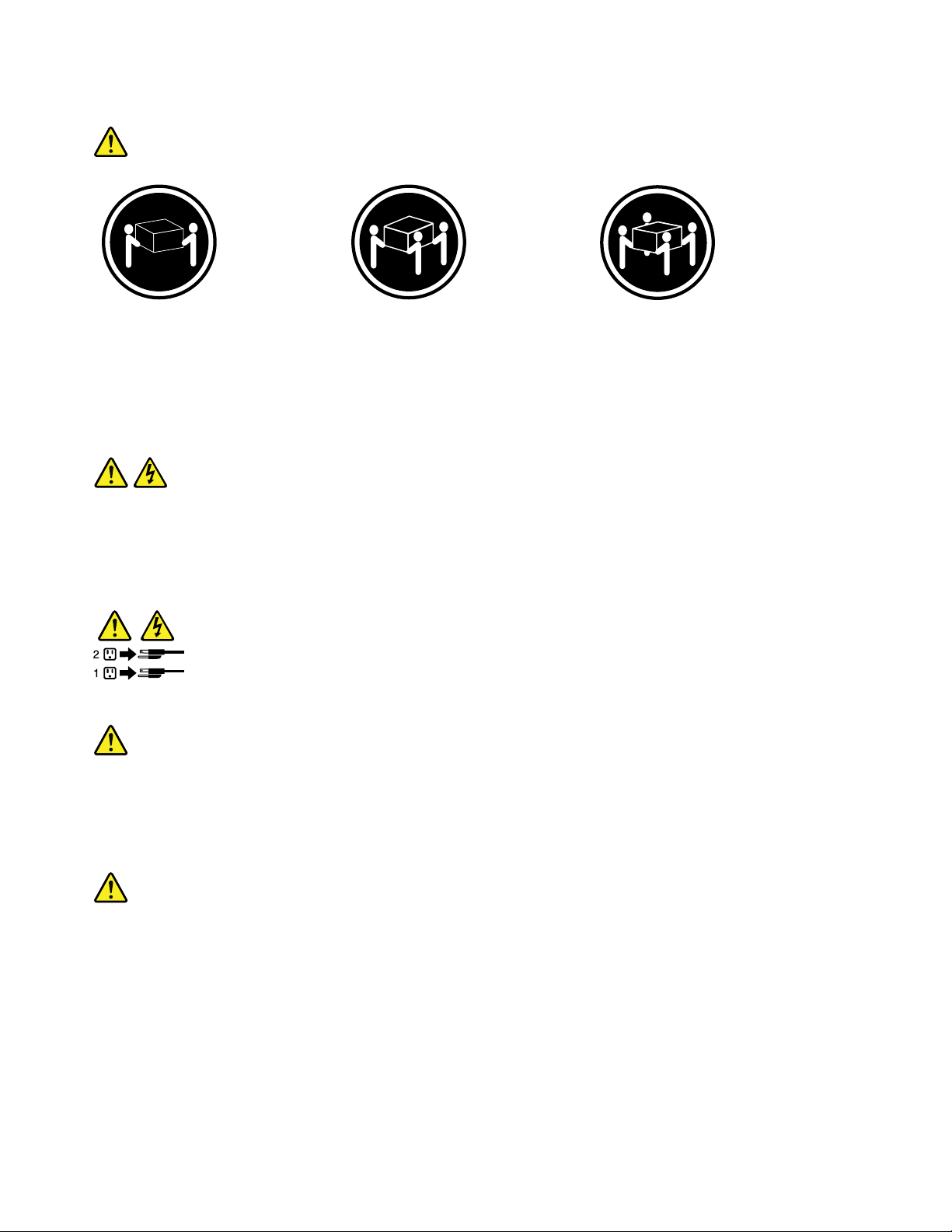
Statement4
≥18kg(39.7lb)≥32kg(70.5lb)≥55kg(121.2lb)
<32kg(70.5lb)<55kg(121.2lb)<100kg(220.5lb)
CAUTION:
Usesafepracticeswhenlifting.
Statement5
CAUTION:
Thepowercontrolbuttononthedeviceandthepowerswitchonthepowersupplydonotturnoff
theelectricalcurrentsuppliedtothedevice.Thedevicealsomighthavemorethanonepower
cord.T oremoveallelectricalcurrentfromthedevice,ensurethatallpowercordsaredisconnected
fromthepowersource.
Statement6
CAUTION:
Ifyouinstallastrain-reliefbracketoptionovertheendofthepowercordthatisconnectedtothe
device,youmustconnecttheotherendofthepowercordtoaneasilyaccessiblepowersource.
Statement7
CAUTION:
Ifthedevicehasdoors,besuretoremoveorsecurethedoorsbeforemovingorliftingthedeviceto
avoidpersonalinjury.Thedoorswillnotsupporttheweightofthedevice.
4ThinkServerTS130HardwareMaintenanceManual
Page 9
Statement8
CAUTION:
Neverremovethecoveronapowersupplyoranypartthathasthefollowinglabelattached.
Hazardousvoltage,current,andenergylevelsarepresentinsideanycomponentthathasthislabel
attached.Therearenoserviceablepartsinsidethesecomponents.Ifyoususpectaproblemwith
oneoftheseparts,contactaservicetechnician.
Statement9
CAUTION:
Toavoidpersonalinjury,disconnectthehot-swapfancablesbeforeremovingthefanfromthedevice.
Statement10
CAUTION:
Thefollowinglabelindicatessharpedges,corners,orjointsnearby.
Statement11
CAUTION:
Thefollowinglabelindicatesahotsurfacenearby.
Statement12
DANGER
Overloadingabranchcircuitispotentiallyarehazardandashockhazardundercertainconditions.T oavoid
thesehazards,ensurethatyoursystemelectricalrequirementsdonotexceedbranchcircuitprotection
requirements.Refertotheinformationthatisprovidedwithyourdeviceforelectricalspecications.
Chapter1.Aboutthismanual5
Page 10
Statement13
CAUTION:
Makesurethattherackissecuredproperlytoavoidtippingwhentheserverunitisextended.
Statement14
CAUTION:
SomeaccessoryoroptionboardoutputsexceedClass2orlimitedpowersourcelimitsandmustbe
installedwithappropriateinterconnectingcablinginaccordancewiththenationalelectriccode.
Statement15
CAUTION:
Thepower-controlbuttononthedevicedoesnotturnofftheelectricalcurrentsuppliedtothe
device.Thedevicealsomighthavemorethanoneconnectiontodcpower.T oremoveallelectrical
currentfromthedevice,ensurethatallconnectionstodcpoweraredisconnectedatthedcpower
inputterminals.
Statement16
CAUTION:
Toreducetheriskofelectricshockorenergyhazards:
•Thisequipmentmustbeinstalledbytrainedservicepersonnelinarestricted-accesslocation,as
denedbytheNECandthelatesteditionofIEC60950,TheStandardforSafetyofInformation
TechnologyEquipment.
•Connecttheequipmenttoareliablygroundedsafetyextralowvoltage(SELV)source.AnSELV
sourceisasecondarycircuitthatisdesignedsothatnormalandsinglefaultconditionsdonot
causethevoltagestoexceedasafelevel(60Vdirectcurrent).
•Thebranchcircuitovercurrentprotectionmustberatedinaccordancewithlocalbuildingcodes.
•Use16AmericanWireGauge(AWG)or1.3mm
2
copperconductoronly,notexceeding3meters
inlength.
•T orquethewiring-terminalscrewsto12inch-pounds(1.4newton-meters).
•Incorporateareadilyavailableapprovedandrateddisconnectdeviceintheeldwiring.
Statement17
CAUTION:
ThisproductcontainsaClass1Mlaser.Donotviewdirectlywithopticalinstruments.
6ThinkServerTS130HardwareMaintenanceManual
Page 11
Statement18
CAUTION:
Donotplaceanyobjectontopofrack-mounteddevices.
Statement19
CAUTION:
Hazardousmovingparts.Keepngersandotherbodypartsaway.
Statement20
CAUTION:
Thebatteryisalithiumionbattery.T oavoidpossibleexplosion,donotburnthebattery.Exchangeit
onlywiththeLenovo-approvedpart.Recycleordiscardthebatteryasinstructedbylocalregulations.
ImportantinformationaboutreplacingRoHScompliantFRUs
RoHS,TheRestrictionofHazardousSubstancesinElectricalandElectronicEquipmentDirective
(2002/95/EC)isaEuropeanUnionlegalrequirementaffectingtheglobalelectronicsindustry.RoHS
requirementsmustbeimplementedonLenovoproductsplacedonthemarketandsoldinthe
EuropeanUnionafterJune2006.ProductsonthemarketbeforeJune2006arenotrequiredto
haveRoHScompliantparts.Ifthepartsarenotcompliantoriginally,replacementpartscanalso
benoncompliant,butinallcases,ifthepartsarecompliant,thereplacementpartsmustalsobe
compliant.
Note:RoHSandnon-RoHSFRUpartnumberswiththesametandfunctionareidentiedwithunique
FRUpartnumbers.
LenovoplanstotransitiontoRoHScompliancewellbeforetheimplementationdateandexpectsitssuppliers
tobereadytosupportLenovo'srequirementsandscheduleintheEU.Productssoldin2005willcontain
someRoHScompliantFRUs.ThefollowingstatementpertainstotheseproductsandanyproductLenovo
producescontainingRoHScompliantparts.
Chapter1.Aboutthismanual7
Page 12
RoHScompliantThinkServer
®
TS130partshaveuniqueFRUpartnumbers.BeforeorafterJune2006,failed
RoHScompliantpartsmustalwaysbereplacedusingRoHScompliantFRUs,soonlytheFRUsidentiedas
compliantinthesystemHardwareMaintenanceManualordirectsubstitutionsforthoseFRUscanbeused.
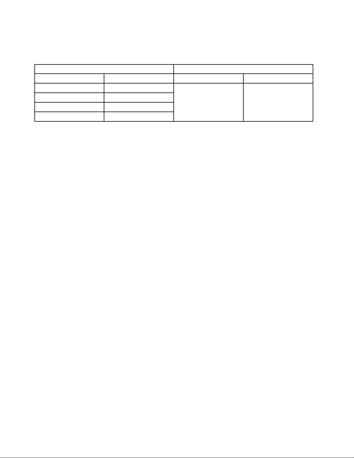
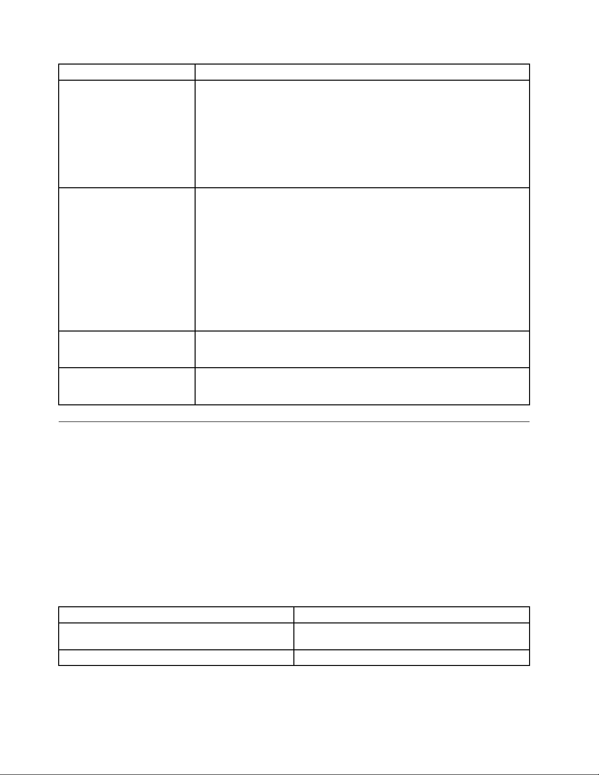
ProductsmarketedbeforeJune2006ProductsmarketedafterJune2006
Currentororiginalpart
Non-RoHSCanbeNon-RoHS
Non-RoHSCanbeRoHS
Non-RoHSCansubtoRoHS
RoHSMustbeRoHS
ReplacementFRU
Currentororiginalpart
MustbeRoHSMustbeRoHS
ReplacementFRU
Note:AdirectsubstitutionisapartwithadifferentFRUpartnumberthatisautomaticallyshippedbythe
distributioncenteratthetimeoforder.
8ThinkServerTS130HardwareMaintenanceManual
Page 13

Chapter2.Generalinformation
Thischapterprovidessomegeneralinformationaboutyourserver.
Featuresandspecications
Thefollowingtableprovidesinformationaboutthefeaturesandspecicationsoftheserver.Depending
ontheservermodel,somefeaturesmightnotbeavailable,orsomespecicationsmightnotapply.For
informationaboutyourspecicmodel,usetheSetupUtilityprogram.See“UsingtheSetupUtilityprogram”
onpage83
.
©CopyrightLenovo2011
9
Page 14
Table1.Featuresandspecications
Microprocessor(s):SupportuptotwoIntel
®
Xeon
dual-core,quad-core,orhex-coremicroprocessors
(internalcachesizevariesbymodeltype)
Forthespecictypeandspeedinformationaboutthe
microprocessor,usetheSetupUtilityprogram.See
“UsingtheSetupUtilityprogram”onpage83
.
Foralistofsupportedmicroprocessors,goto
http://www.lenovo.com/thinkserverandclickOptions
undertheProductstab.
Memory
•SupportsuptofourDDR3ECCUDIMMs(doubledata
rate3errorcorrectioncodeunbuffereddualinline
memorymodules)
•Types:1333MHz,DDR3registeredSDRAMDIMMs
Internaldrives
•SerialAdvancedTechnologyAttachment(SATA)hard
diskdrive
•SATAopticaldrive
Videosubsystem
•IntegratedgraphicsforaVideoGraphicsArray(VGA)
connectorandaDisplayPortconnector
Connectivity
•100/1000MbpsintegratedEthernetcontroller
Powersupply:Yourservercomeswithoneofthe
followingpowersupplies:
•280–wattauto-sensingpowersupply
•320–wattauto-sensingpowersupply
®
Expansion
•Twoopticaldrivebays
•Twoharddiskdrivebays
•TwoPCIcardslots
•OnePCIExpressx1cardslot
•OnePCIExpressx16cardslot
Systemmanagementfeatures
•Abilitytostorepower-onself-test(POST)hardware
testresults
•Automaticpower-onstartup
•IntelActiveManagementTechnology(AMT)
•IntelHyper-Threadingtechnology(somemodels)
•IntelRapidStorageT echnology(RST)
•PrebootExecutionEnvironment(PXE)
•SystemManagement(SM)UEFIandSMsoftware
•WakeonLAN
•WakeonRing(intheSetupUtilityprogram,thisfeature
iscalledSerialPortRingDetectforanexternalmodem)
Input/Output(I/O)features
•EightUniversalSerialBus(USB)connectors(twoon
thefrontpanelandsixontherearpanel)
•One9-pinserialport
•OneEthernetconnector
•OneDisplayPortconnector
•OneVGAmonitorconnector
•Threeaudioconnectorsontherearpanel(audioline-in
connector,audioline-outconnector,andmicrophone
connector)
10ThinkServerTS130HardwareMaintenanceManual
Preinstalledoperatingsystem
Somemodelsarepreinstalledwithoneofthefollowing
operatingsystems:
•Microsoft
•MicrosoftWindows
®
WindowsServer
®
®
2008R2Foundation
SmallBusinessServer(SBS)
Aurora
Operatingsystem(s),supported
•MicrosoftWindowsServer2008R2Foundation
•MicrosoftWindowsServer2008R2(ServicePack1)
•MicrosoftWindowsSmallBusinessServer(SBS)
Aurora
•MicrosoftWindowsSmallBusinessServer(SBS)7
•MicrosoftWindowsMultipointServer
Page 15
Table1.Featuresandspecications(continued)
Integratedfunctions:
•Ethernetcontrollers(Theservercomeswithtwo
integratedGigabitEthernetcontrollers,whichsupport
connectionto100Mbpsor1000Mbpsnetwork.)
•Oneserialport
•OneVideoGraphicsArray(VGA)monitorconnector
•SixUSBconnectors(twofrontandfourrear)
•OneRJ-45Ethernetconnectorsontherearpanel
•EightdiagnosticLEDs
Size:
•Width:174.8mm(6.88inches)
•Height:377.3mm(14.85inches)
•Depth:406.7mm(16.01inches)
Weight:Maximumconguration:11.2kg(24.7lbs)
Electricalinput
•Inputvoltage:
–Lowrange:
Minimum:90Vac
Maximum:137Vac
–Highrange:
Minimum:180Vac
Maximum:264Vac
Environment
•Airtemperature:
Operating:10°Cto35°C(50°Fto95°F)
Non-operating:-40°Cto60°C(14°Fto140°F)(with
package)
Non-operating:-10°Cto60°C(14°Fto140°F)
(withoutpackage)
•Humidity:
Operating:10%to80%(non-condensing)(10%
perhour)
Non-operating:10%to90%(non-condensing)
(10%perhour)
•Altitude:
Operating:-50to10000ft(-15.2to3048m)
Non-operating:-50to35000ft(-15.2to10668m)
Securityfeatures
•Computrace
•Enablingordisablingadevice
•EnablingordisablingUSBconnectorsindividually
•Harddiskdrivepassword
•Power-OnPassword(POP)andAdministrator
PasswordforUEFIaccess
•Startupsequencecontrol
•Startupwithoutkeyboardormouse
•Supportforanintegratedcablelock(Kensingtonlock)
•Supportforapadlock
•TrustedPlatformModule(TPM)
Softwareprograms
Lenovoprovidessoftwaretohelpgetyourserverupandrunning.
EasyStartup
TheThinkServerEasyStartupprogramsimpliestheprocessofconguringRAIDandinstallingsupported
MicrosoftWindowsandLinuxoperatingsystemsanddevicedriversonyourserver.TheEasyStartupprogram
isprovidedwithyourserverontheThinkServerEasyStartupDVD.TheDVDisself-starting(bootable).The
userguidefortheEasyStartupprogramisontheDVDandcanbeaccesseddirectlyfromtheprogram
interface.Foradditionalinformation,see“UsingtheThinkServerEasyStartupprogram”onpage102
.
Reliability,availability,andserviceability
Reliability,availability,andserviceability(hereafterreferredtoasRAS)arethreeimportantserverdesign
features.TheRASfeatureshelpyoutoensuretheintegrityofthedatastoredontheserver,theavailabilityof
theserverwhenyouneedit,andtheeasewithwhichyoucandiagnoseandcorrectproblems.
TheserverhasthefollowingRASfeatures:
Chapter2.Generalinformation11
Page 16

•AdvancedCongurationandPowerInterface(ACPI)
•AdvancedDesktopManagementInterface(DMI)
•Automaticmemorydownsizingonerrordetection
•Automaticrestartonnon-maskableinterrupt(NMI)
•Availabilityofmicrocodelevel
•Built-in,menu-drivensetup,systemconguration,andRAIDconguration
•Built-inmonitoringforfan,temperature,andvoltage
•Coolingfanswithspeed-sensingcapability
•ECCDDR3SDRAMwithSerialPresenceDetect(SPD)
•Errorcodesandmessagestohelpyouidentifyproblems
•Generatingerrorlogsforthepower-onself-test(POST)failures
•Hot-swapSASharddiskdrives
•IntegratedEthernetcontrollers
•IntelligentPlatformManagementInterface(IPMI)2.0
•Power-onself-test(POST)
•Standbyvoltageforsystem-managementfeaturesandmonitoring
•System-errorlight-emittingdiode(LED)onthefrontpanel
•Vitalproductdata(VPD),includingtheserialnumberinformationandreplacementpartnumbers,storedin
thenonvolatilememoryforeasierremotemaintenance
12ThinkServerTS130HardwareMaintenanceManual
Page 17

Chapter3.Diagnosticsandtroubleshooting
Thischapterintroducessomebasicdiagnosticandtroubleshootingprograms.Ifyourserverproblemisnot
describedhere,seeAppendixB“Helpandservice”onpage107
Thischapterprovidesinstructionsonthefollowingtopics:
•“PC-DoctorforDOS”onpage13
•“Basictroubleshooting”onpage15
•“T roubleshootingtables”onpage16
PC-DoctorforDOS
ThePC-DoctorforDOSdiagnosticprogramisusedtotesthardwarecomponentsofyourserver.Itisalso
usedtoreportoperating-system-controlledsettingsthatinterferewiththecorrectoperationofyourserver.If
youareunabletoisolateandrepairtheproblemyourselfafterrunningthePC-DoctorforDOSdiagnostic
program,saveandprinttheloglescreatedbythePC-DoctorforDOSdiagnosticprogram.Y ouwillneed
thelogleswhenyouspeaktoaLenovotechnicalsupportrepresentative.
YoucandownloadthelatestversionofthePC-DoctorforDOSdiagnosticprogramfrom
http://www.lenovo.com/support.ThePC-DoctorforDOSdiagnosticprogramrunsindependentlyofthe
Windowsoperatingsystem.UsethePC-DoctorforDOSdiagnosticprogramifyouareunabletostartthe
Windowsoperatingsystem.YoucanrunthePC-DoctorforDOSdiagnosticprogramfromadiagnostic
discthatyoucreated.
foradditionaltroubleshootingresources.
Creatingadiagnosticdisc
Thissectionprovidesinstructionsonhowtocreateadiagnosticdisc.
Tocreateadiagnosticdisc,dothefollowing:
1.Downloadaself-startingbootableCD/DVDimage(knownasanISOimage)ofthediagnosticprogram
fromhttp://www.lenovo.com/support.
2.UseanyCD/DVDburningsoftwaretocreateadiagnosticdiscwiththeISOimage.
Runningthediagnosticprogramfromadiagnosticdisc
Thissectionprovidesinstructionsonhowtorunthediagnosticprogramfromadiagnosticdiscthatyou
created.
Torunthediagnosticprogramfromadiagnosticdiscthatyoucreated,dothefollowing:
1.Makesuretheopticaldriveyouwanttouseissetastherstbootdeviceinthestartupdevicesequence.
2.Makesuretheserveristurnedonandtheninsertthediscintotheopticaldrive.Thediagnostic
programopens.
Note:Youcaninsertthediscintotheopticaldrivewhenyouaresettingthestartupdevicesequence.
However,ifyouinsertthediscintotheopticaldrivewhenyouhavealreadyenteredtheoperating
system,youneedtorestarttheservertoaccessthediagnosticprogram.
3.Followtheinstructionsonthescreentoselectthediagnostictestthatyouwanttorun.
Note:Foradditionalhelp,presstheF1key.
©CopyrightLenovo2011
13
Page 18

4.Removethediagnosticdiscfromtheopticaldrivewhenyoucompletethediagnosticprocess.
Navigatingthroughthediagnosticprogram
Usethecursormovementkeystonavigatethroughthemenus.
•Toselectamenuitem,pressEnter.
•Toreturntothepreviousmenu,pressEsc.
•Toviewthehelpinformationsystem,pressF1.
Runningtests
Therearefourwaystorunthediagnostictests.
•Usingthecursormovementkeys,selectRunNormalTestorRunQuickT estfromtheDiagnosticsmenu
andthenpressEnter.Thisautomaticallyrunsapre-denedgroupoftestsfromeachtestcategory.By
selectingRunQuickT est,aquicktestwillbestarted.ByselectingRunNormalTest,amoreextensive
setoftestswillbestartedandwilltakelongertocomplete.
•PressF5toautomaticallyrunallselectedtestsinallcategories.
•Fromwithinatestcategory,pressCtrl+Entertoautomaticallyrunonlytheselectedtestsinthatcategory.
•Usingthecursormovementkeys,highlightasingletestwithinatestcategory,andthenpressEnter.
Thisrunsonlythattest.
PressEscatanytimetostopthetestingprocess.
Testresults(N/A,PASSED,FAILED,ABORTED)aredisplayedintheeldbesidethetestdescriptionandin
thetestlog.See“Viewingthetestlog”onpage15.
Toselectoneormoretests,dothefollowing:
1.Openthecorrespondingtestcategory.
2.Usingthecursormovementkeys,selectthedesiredtest.
3.Pressthespacebar.Aselectedtestismarkedby>>.Pressingthespacebaragainde-selectsa
testandremovesthe>>mark.
4.Repeatsteps2and3abovetoselectalldesiredtests.
Testresults
Diagnosticstestresultsproducethefollowingerrorcodeformat:
FunctionCode
•FunctionCode:Representsthefeatureorfunctionwithintheserver.
•FailureT ype:Representsthetypeoferrorencountered.
•DeviceID:Containsthecomponent'sunitIDthatcorrespondstoacertaindiskdrive,removablemedia
drive,serialorparallelport,processor,specicRIMM,oradeviceonthePCIbus.
•Date:Containsthedatewhenthediagnostictestwasrun.ThedateisretrievedfromCMOSandis
displayedintheYYYYMMDDformat.
•ChkDigits:Containsa2-digitcheck-digitvaluetoensurethefollowing:
FailureTypeDeviceIDDate
ChkDigits
Text
–Diagnosticswererunonthespecieddate.
–Diagnosticswererunonthespeciedserver.
–Thediagnosticerrorcodeisrecordedcorrectly.
14ThinkServerTS130HardwareMaintenanceManual
Page 19

•T ext:Descriptionoftheerror.
Note:See“POSTerrorcodes”onpage17
forerrorcodelistings.
Formattingtheharddiskdrive
Thediagnosticsprogramofferstwoharddiskdriveformattingmethods:
•QuickErase
•FullErase
ThequickerasemethodprovidesaDOSutilitythatperformsthefollowing:
•DestroystheMasterBootRecord(MBR)ontheharddiskdrive.
•DestroysallcopiesoftheFATTableonallpartitions(boththemasterandbackup).
•Destroysthepartitiontable.
•Providesmessagesthatwarntheuserthatthisisanon-recoverableprocess.
ThefullerasemethodprovidesaDOSutilitythatperformsthefollowing:
•Performsallthestepsinquickerase.
•ProvidesaDOSutilitythatwritesrandomdatatoallsectorsoftheharddiskdrive.
•Providesanestimateoftimetocompletionalongwithavisualrepresentationofcompletionstatus.
•Providesmessagesthatwarntheuseraboutanon-recoverableprocess.
Important:Makesurethatalldataisbackedupbeforeusingthequickeraseorfullerasefunction.
Torunaquickeraseorfulleraseoperation,dothefollowing:
1.SelecttheUTILITYoptiononthetoolbarandpressEnter.
2.SelecteithertheQUICKERASEHARDDISKorFULLERASEHARDDISKoptionandfollowthe
instructionsonthescreen.
Viewingthetestlog
Errorsreportedbythediagnostictestwillbedisplayedasafailure.
Toviewdetailsofafailureortoviewalistoftestresults,usethefollowingprocedurefromanytestcategory
screen:
1.PressF3toactivatethelogle.
2.PressF3againtosavetheleorpressF2toprintthele.
Basictroubleshooting
Thefollowingtablesprovideinformationtohelpyoutroubleshootyourserverproblems.
Note:Ifyoucannotcorrecttheproblem,havetheserverserviced.Foralistofserviceandsupporttelephone
numbers,refertotheWarrantyandSupportInformationdocumentat:
http://www.lenovo.com/support/phone
Generalproblems
Thefollowingtabledescribesthegeneralproblemsandsuggestedactionstocorrectdetectedproblems.
Chapter3.Diagnosticsandtroubleshooting15
Page 20
SymptomAction
Theserverdoesnotstartwhen
youpressthepowerswitch.
Themonitorscreenisblank.
Theoperatingsystemdoesnot
start.
Theserverbeepsmultipletimes
beforetheoperatingsystem
starts.
Verifythat:
•Thepowercordiscorrectlyconnectedtotherearoftheserverandtoaworking
electricaloutlet.
•Ifyourserverhasasecondarypowerswitchontherearoftheserver,makesure
thatitisswitchedon.
•Thepowerindicatoronthefrontoftheserverison.
•Theservervoltagematchesthevoltageavailableattheelectricaloutletforyour
countryorregion.
Verifythat:
•Themonitorsignalcableiscorrectlyconnectedtothemonitorandtothe
appropriatemonitorconnectorontheserver.
•Themonitorpowercordiscorrectlyconnectedtothemonitorandtoaworking
electricaloutlet.
•Themonitoristurnedonandthebrightnessandcontrastcontrolsareset
correctly.
•Theservervoltagematchesthevoltageavailableattheelectricaloutletforyour
countryorregion.
•Ifyourserverhastwomonitorconnectors,besuretousetheconnectoron
thegraphicscard.
Verifythatthestartupsequenceincludesthedevicewheretheoperatingsystem
resides.Usually,theoperatingsystemisontheharddiskdrive.Formore
information,see“Selectingastartupdevice”onpage99.
Verifythatnokeysarestuck.
Troubleshootingtables
Usethetroubleshootingtablestondsolutionstoproblemsthathaveidentiablesymptoms.
Ifyouhavejustaddednewsoftwareoranewoptionaldeviceandtheserverisnotworking,dothefollowing
beforeusingthetroubleshootingtables:
1.Checkthesystem-errorLEDontheoperatorinformationpaneltoseeifitislit.
2.Removethesoftwareordevicethatyoujustadded.
3.Runthediagnosticteststodeterminewhethertheserverisrunningcorrectly.
4.Reinstallthenewsoftwareornewdevice.
Harddiskdrivebooterror
Aharddiskdrivebooterrorcanhavethefollowingcauses.
SymptomFRU/Action
Thestartupdriveisnotinthebootsequencein
conguration.
Nooperatingsystemisinstalledonthebootdrive.Installanoperatingsystemonthebootdrive.
Checkthecongurationandensurethestartupdriveis
inthebootsequence.
16ThinkServerTS130HardwareMaintenanceManual
Page 21

SymptomFRU/Action
Thebootsectoronthestartupdriveiscorrupted.
Thedriveisdefective.
Thedrivemustbeformatted.Dothefollowing:
1.Attempttobackupthedataonthefailingharddisk
drive.
2.Usingtheoperatingsystemprograms,formatthe
harddiskdrive.
Replacetheharddiskdrive.
Powersupplyproblems
Ifyoususpectapowersupplyproblem,usethefollowingprocedures.
Check/VerifyFRU/Action
Checkthefollowingforproperinstallation.
•Powercord
•On/Offswitchconnector
•On/Offswitchpowersupplyconnector
•Systemboardpowersupplyconnectors
•Microprocessorconnection
Checkthepowercordforcontinuity.
Checkthepower-onswitchforcontinuity.
Reseatconnectors.
Powercord
Power-onswitch
Beepsymptoms
Beepsymptomsaretonesoraseriesoftonesseparatedbypauses(intervalswithoutsound)duringthePOST.
Thefollowingtabledescribesbeepsymptomsandprovidessuggestedactionstocorrectdetectedproblems.
SymptomErrorFRU/Action
3shortbeepsand1longbeepMemorynotdetected
2shortbeeps
CommonPOSTerror
Performthefollowingactionsinorder:
1.Makesurethatthememory
module(s)areproperlyseatedin
theconnector(s).
2.Replacethememorymodule(s).
3.Replacethesystemboard.
Indicatesthatanerrorhasoccurred
duringthePOST.
POSTerrorcodes
Eachtimeyouturnonthesystem,itperformsaseriesofteststhatcheckstheoperationofthesystemand
options.Thisseriesoftestsiscalledthepower-onself-test,orPOST.
ThePOSTperformsthefollowingoperations:
•Checkssomebasicsystemboardoperations
•Checksthememoryoperation
•Checksthevideooperation
•Veriesthatthebootdriveisworking
Chapter3.Diagnosticsandtroubleshooting17
Page 22

IfthePOSTdetectsaproblem,anerrormessagewillbedisplayedonthescreen.Asingleproblemcan
causeseveralerrormessages.Whenyoucorrectthecauseofthersterrormessage,probablytheother
errormessageswillnotbedisplayedthenexttimeyouturnonthecomputer.
POSTerrorcodePOSTerrormessageDescription/Action
00CEMachineTypeorSerialNumberisINVALID
0210
0211
0135
0164MemorysizedecreasedThiserrormessageisdisplayedwhenthememory
1762
Stuckkey
Keyboardnotfound
Fanfailure
Congurationchangehasoccurred
Thiserrormessageisdisplayedwhenthemachine
typeortheserialnumberisinvalid.
Thiserrormessageisdisplayedwhenakeyiskept
pressedforalongtime.
Thiserrormessageisdisplayedwhenthereisno
keyboarddetected.
Thesystemmightbeoverheating.
PressF1toentertheSetupUtilityprogram.Then
pressF10tosavetheoperationandexittheSetup
Utilityprogram.
Note:Iftheproblemiscausedbythe
microprocessorfan,pressingF10willnotsolve
theproblem.
sizehasdecreased.
PressF1toentertheSetupUtilityprogram.Then
pressF10tosavetheoperationandexittheSetup
Utilityprogram.
Thiserrormessageisdisplayedwhenaharddisk
driveoropticaldrivechangehasbeenmade.
PressF1toentertheSetupUtilityprogram.Then
pressF10tosavetheoperationandexittheSetup
Utilityprogram.
1820
1962
0162
0167
0175
Morethanoneexternalngerprintreader
isattached.Poweroffandremoveallbut
thereaderthatyousetupwithinyourmain
operatingsystem.
Nooperatingsystemfound.Pressanykey
torepeatbootsequence.
SetupdataintegritycheckfailurePressF1toentertheSetupUtilityprogram.Then
Noprocessormicrocodeupdatefound
Systemsecurity-SecuritydatacorruptedPressF1toentertheSetupUtilityprogram.Then
Ifmorethanoneexternalngerprintreaderis
connectedtoacomputer,thiserrormessagewill
bedisplayedtoinformyoutoremoveallofthe
ngerprintkeyboardsexcepttheonecompatible
withthengerprintapplicationonyourcomputer.
ThiserroroccursonlyafterthePOSTiscompleted.
Pressanykeytorepeatbootsequence.
pressF10tosavetheoperationandexittheSetup
Utilityprogram.
Thiserrormessageindicatesthatthereis
nomicrocodeupdateimageforthecurrent
microprocessor.
pressF10tosavetheoperationandexittheSetup
Utilityprogram.
18ThinkServerTS130HardwareMaintenanceManual
Page 23
POSTerrorcodePOSTerrormessageDescription/Action
0176
0189
0197
0190
0199
Systemsecurity-Thesystemhasbeen
tamperedwith
Systemsecurity-Cannotreadthe
SecurityEEPROM
Systemsecurity-Unauthorizedsecurity
datachangedetected
Systemsecurity-Invalidsecuritychange
requested
Systemsecurity-Securitypasswordretry
countexceeded
Thiserrormessageisdisplayedwhenthe
computeristurnedonwiththecoveropenor
removed.
PressF1toentertheSetupUtilityprogram.Then
pressF10tosavetheoperationandexittheSetup
Utilityprogram.
ThiserrormessageindicatesthattheSecurity
EEPROMmightbebrokenorhavebeenremoved.
PressF1toentertheSetupUtilityprogram.Then
pressF10tosavetheoperationandexittheSetup
Utilityprogram.
PressF1toentertheSetupUtilityprogram.Then
pressF10tosavetheoperationandexittheSetup
Utilityprogram.
PressF1toentertheSetupUtilityprogram.Then
pressF10tosavetheoperationandexittheSetup
Utilityprogram.
PressF1toentertheSetupUtilityprogram.Then
pressF10tosavetheoperationandexittheSetup
Utilityprogram.
EasyStartupproblems
ThefollowingtabledescribestheEasyStartupproblemsandprovidessuggestedactionstocorrectdetected
problems.
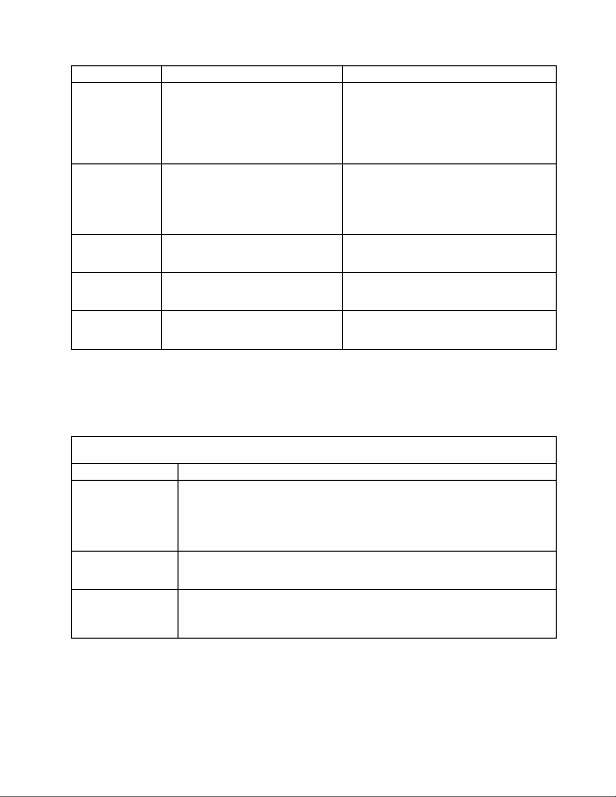
Table2.ThinkServerEasyStartupDVD
FollowthesuggestedactionsintheorderinwhichtheyarelistedintheActioncolumnuntiltheproblem
isresolved.
Symptom
TheThinkServer
EasyStartupDVDwill
notstart.
Theoperatingsystem
installationprogram
continuouslyloops.
TheEasyStartup
programwillnotstart
theoperatingsystem
medium.
Action
•MakesuretheserversupportstheEasyStartupprogramandhasastartable(bootable)
DVDdrive.
•Ifthestartup(boot)sequencesettingshavebeenchanged,makesuretheDVDdrive
isrstinthestartupsequence.
•IfmorethanoneDVDdriveisinstalled,makesurethatonlyoneDVDdriveissetasthe
primarydrive.StarttheEasyStartupDVDfromtheprimaryDVDdrive.
Makemorespaceavailableontheharddiskdrive.
MakesurethattheoperatingsystemmediumissupportedbytheEasyStartupprogram.
SeetheEasyStartupUserGuideforalistofsupportedoperatingsystemversions.The
EasyStartupUserGuideandcompatibilitynotesareavailablethroughtheEasyStartup
program.
Chapter3.Diagnosticsandtroubleshooting19
Page 24
Miscellaneouserrormessages
SymptomFRU/Action
ChangingdisplaycolorsDisplay/Monitor
Computerwillnotturnoff.See“Harddiskdriveboot
error”onpage17.
ComputerwillnotRPLfromserver
ComputerwillnotperformaWakeOnLAN®(ifapplicable)1.Checkthepowersupplyandsignalcableconnections
Deadcomputer.See“Harddiskdrivebooterror”onpage
17.
Diskettedrivein-uselightremainsonordoesnotlight
whendriveisactive.
Blankscreenexceptforashingcursor.
IncorrectmemorysizeduringPOST
"InsertaDiskette"iconappearswithaknown-good
diagnosticsdisketteintherst3.5-inchdiskettedrive.
Intensityorcolorvariesfromlefttorightofcharacters
andcolorbars
Nopowerorfannotrunning
Non-systemdiskordiskerror-typemessagewitha
known-gooddiagnosticdiskette.
1.Powerswitch
2.Systemboard
3.Risercard,ifinstalled.
1.EnsurethatNetworkissetastherstdeviceoritis
afterCD/DVDinthestartupsequence.
2.EnsurethatthenetworkadapterisenabledforRPL.
3.Networkadapter(Advisethenetworkadministrator
ofnewMACaddress)
tothenetworkadapter.
2.Ensurethattheoperatingsystemsettingsaresetto
enableWakeonLAN.
3.EnsurethattheWakeOnLANfeatureisenabledin
Setup/Conguration(see“StartingtheSetupUtility
program”onpage83.)
4.Ensurethatthenetworkadministratorisusingthe
correctMACaddress.
5.EnsurethatnointerruptorI/Oaddressconicts.
6.Checkthenetworkadapter.
1.Powersupply
2.Systemboard
1.Diskettedrive
2.Systemboard
3.Diskettedrivecable
1.Systemboard
2.Primaryharddiskdrive
3.Harddiskdrivecable
1.Runthememorytests.
2.Checkthememorymodules.
3.Checkthesystemboard.
1.Systemboard
2.Diskettedrivecable
3.Networkadapter
1.Display
2.Videoadapter(ifpresent)
3.Systemboard
See“Harddiskdrivebooterror”onpage17.
1.Diskettedrive
2.Systemboard
3.Diskettedrivecable
20ThinkServerTS130HardwareMaintenanceManual
Page 25

SymptomFRU/Action
Otherdisplaysymptomsnotlistedabove(includingblank
orillegibledisplay)
Turnonindicatororharddiskdrivein-uselightnoton,but
computerworkscorrectly
Printerproblems1.Printer
Programloadsfromtheharddiskwithaknown-good
diagnosticsdisketteintherst3.5-inchdiskettedrive
RPLcomputercannotaccessprogramsfromitsownhard
diskdrive.
RPLcomputerdoesnotRPLfromserver
Serialorparallelportdevicefailure(systemboardport)
Serialorparallelportdevicefailure(adapterport)
Someorallkeysonthekeyboarddonotwork
1.Display
2.Systemboard
1.Powerswitch/LEDassembly
2.Systemboard
2.Systemboard
1.RuntheSetupUtilityprogramandcheckstartup
sequence.
2.Checkthediskettedrive.
3.Checkthediskettedrivecable.
4.Checkthesystemboard.
5.Checkthepowersupply.
1.IfthenetworkadministratorisusingtheLCCMHybrid
RPL,checkstartupsequence:
a.Firstdevice-Network
b.Seconddevice-Harddiskdrive
2.Checktheharddiskdrive.
1.Checkthestartupsequence.
2.CheckthenetworkadapterLEDstatus.
1.Runanexternaldeviceself-test.
2.Checktheexternaldevice.
3.Checkthecable.
4.Checkthesystemboard.
1.Runanexternaldeviceself-test.
2.Checktheexternaldevice.
3.Checkthecable.
4.Checkthealternateadapter.
5.Checkthesystemboard.
1.Keyboard
2.Keyboardcable
3.Systemboard
Undeterminedproblems
Thistopicprovidesinstructionsonhowtondoutthefailingcomponents.
Tondoutthefailingcomponents,dothefollowing:
1.T urnofftheserver.
2.Removeordisconnectthefollowingcomponents(ifinstalled)oneatatime.
a.Externaldevices(modem,printer,ormouse)
b.Anyadapters
c.Memorymodules
d.Extendedvideomemory
Chapter3.Diagnosticsandtroubleshooting21
Page 26

e.Externalcache
f.ExternalcacheRAM
g.Harddiskdrive
h.Diskettedrive
3.T urnontheservertore-testthesystem.
4.Repeatsteps1through3untilyoundthefailingcomponents.Ifalldevicesandadaptershavebeen
removed,andtheproblemcontinues,replacethesystemboard.
22ThinkServerTS130HardwareMaintenanceManual
Page 27
Chapter4.Locatingparts,controls,LEDs,andconnectors
Thischapterprovidesinformationtohelpyoulocateyourserverparts,controls,light-emittingdiodes
(LEDs),andconnectors.
Frontview
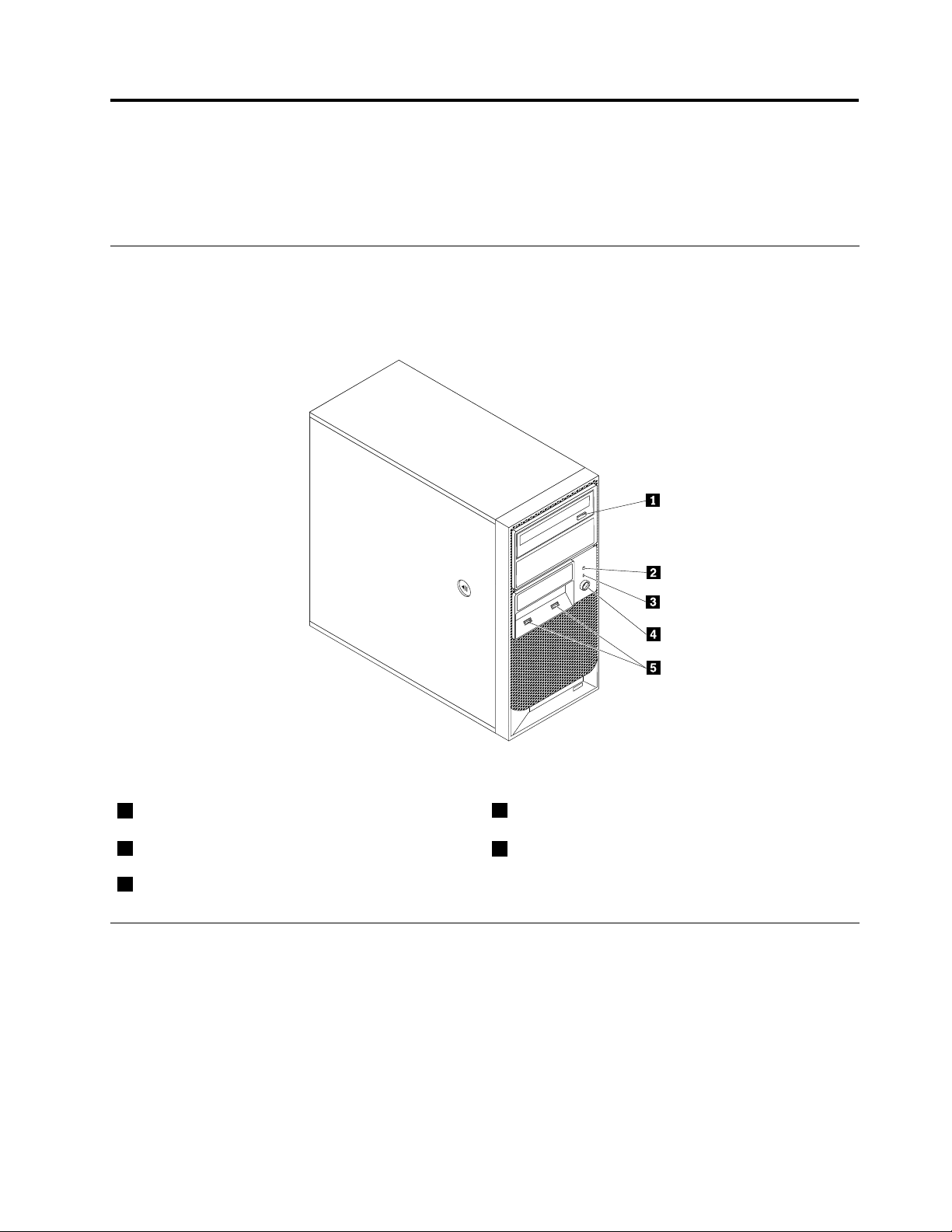
Figure1“Frontcontrolandconnectorlocations”onpage23showsthelocationsofthecontrolsand
connectorsonthefrontofyourserver.
Figure1.Frontcontrolandconnectorlocations
1Opticaldriveeject/closebutton
2HarddiskdriveactivityLED
3Power-onLED
4Powerswitch
5USBconnectors(2)
FrontcontrolpanelLEDs
ThefollowingtabledescribesthemeaningoftheLEDsonthefrontcontrolpanel.
©CopyrightLenovo2011
23
Page 28
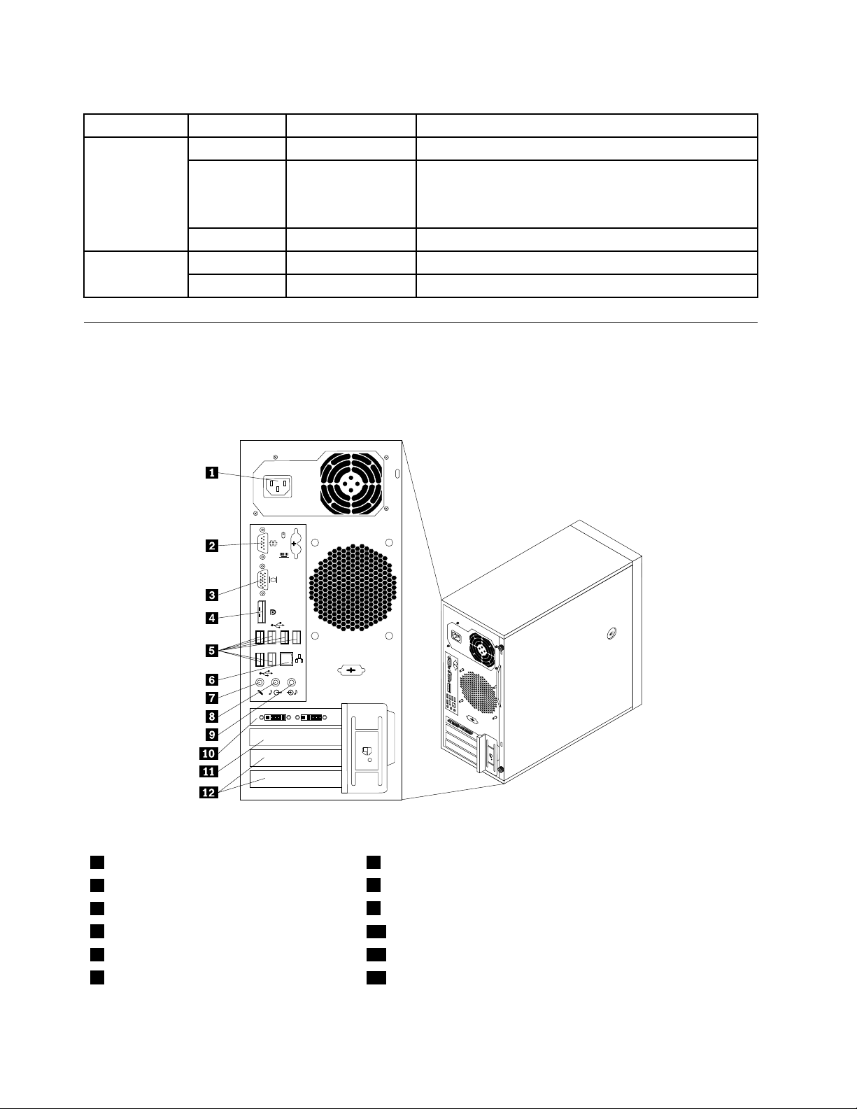
Table3.FrontcontrolpanelLEDs
LEDStateColorDescription
PowerLED
OnGreen
Blinking
GreenTheserverpowerisinACPIS1mode,whichisalso
Theserverpowerison.
knownasPowerOnSuspend(POS)mode.Inthismode,
themicroprocessorisnotworkingwhileotherhardware
devicesarestillworking.
OffOff
OffOff
LED
Blinking
Green
Theserverpowerisoff.
Theharddiskdriveisnotactive. Harddiskdrive
Theharddiskdriveisactive.
Rearview
Figure2“Rearconnectorlocations”onpage24showsthelocationsoftheconnectorsontherearof
yourserver.Someconnectorsontherearofyourserverarecolor-codedtohelpyoudeterminewhereto
connectthecablesinyourserver.
Figure2.Rearconnectorlocations
1Powercordconnector7Microphoneconnector
2Serialport
3VGAmonitorconnector
4DisplayPortconnector
5USBconnectors(6)11PCIExpressx1cardslot
6Ethernetconnector
8Audioline-outconnector
9Audioline-inconnector
10PCIExpressx16cardslot
12PCIcardslots(2)
24ThinkServerTS130HardwareMaintenanceManual
Page 29

ConnectorDescription
Audioline-inconnector
Usedtoreceiveaudiosignalsfromanexternalaudiodevice,suchasastereo
system.Whenyouattachanexternalaudiodevice,acableconnectstheaudio
line-outconnectorofthedevicetotheaudioline-inconnectoroftheserver.
Audioline-outconnector
Usedtosendaudiosignalsfromtheservertoexternaldevices,suchaspowered
stereospeakers(speakerswithbuilt-inampliers),headphones,multimedia
keyboards,ortheaudioline-inconnectoronastereosystemorotherexternal
recordingdevice.
DisplayPortconnector
Usedtoattachahigh-performancemonitor,adirect-drivemonitor,orotherdevices
thatuseaDisplayPortconnector.
Ethernetconnector
UsedtoattachanEthernetcableforalocalareanetwork(LAN).
Note:T ooperatetheserverwithinFCCClassBlimits,useaCategory5Ethernet
cable.
Microphoneconnector
Usedtoattachamicrophonetoyourserverwhenyouwanttorecordsoundorif
youusespeech-recognitionsoftware.
Serialport
Usedtoattachanexternalmodem,aserialprinter,orotherdevicesthatusea
9-pinserialport.
USBconnectorUsedtoattachadevicethatrequiresaUSBconnector,suchasaUSBkeyboard,a
USBmouse,aUSBscanner,oraUSBprinter.IfyouhavemorethaneightUSB
devices,youcanpurchaseaUSBhub,whichyoucanusetoconnectadditional
USBdevices.
VGAmonitorconnectorUsedtoattachaVGAmonitororotherdevicesthatuseaVGAmonitorconnector.
Chapter4.Locatingparts,controls,LEDs,andconnectors25
Page 30
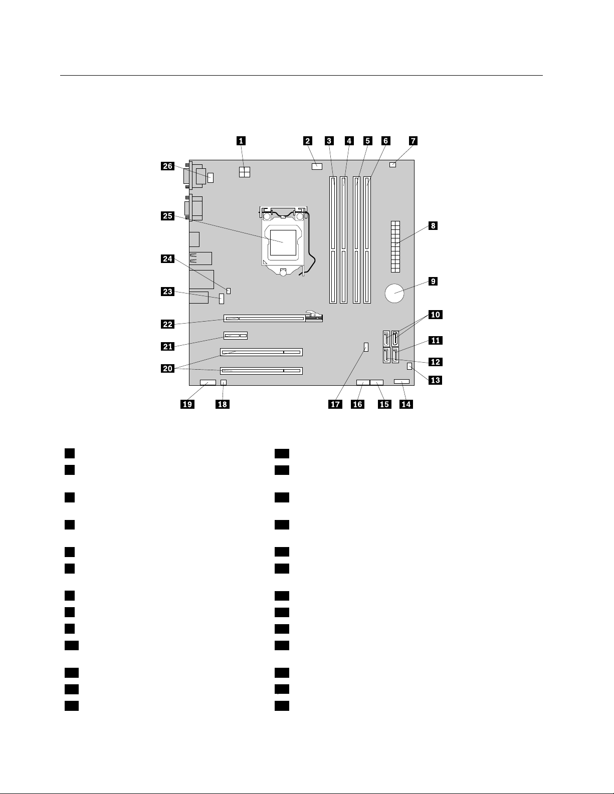
Locatingpartsonthesystemboard
Figure3“Systemboardpartlocations”onpage26showsthelocationsofthepartsonthesystemboard.
Figure3.Systemboardpartlocations
14-pinpowerconnector
2Microprocessorfanconnector
14FrontpanelconnectorforpowerswitchandLEDindicators
15FrontUSBconnector1(forconnectingUSBport1and2
onthefrontbezel)
3Memoryslot1(DIMM1)16FrontUSBconnector2(forconnectingadditionalUSB
devices)
4Memoryslot2(DIMM2)17ClearCMOS(ComplementaryMetalOxideSemiconductor)
/Recoveryjumper
5Memoryslot3(DIMM3)
6Memoryslot4(DIMM4)19Frontaudioconnector(forconnectingthemicrophoneand
18Internalspeakerconnector
headphoneconnectorsonthefrontbezel)
7Thermalsensorconnector
824-pinpowerconnector
9Battery
10SATAconnectors1and2(SATA3.0
20PCIcardslots(2)
21PCIExpressx1cardslot
22PCIExpressx16graphicscardslot
23Rearfanconnector
connectors)
11SATAconnector3(SATA2.0connector)24Coverpresenceswitchconnector(Intrusionswitchconnector)
12eSATAconnector
13Frontfanconnector
25Microprocessor
26PS/2keyboardandmouseconnector
26ThinkServerTS130HardwareMaintenanceManual
Page 31

Internalcomponents
Figure4“Componentlocations”onpage27showsthelocationsofthevariouscomponentsinyourserver.To
removetheservercoverandaccesstotheinsideoftheserver,see“Removingtheservercover”onpage33.
Figure4.Componentlocations
1
Heatsink
2
Microprocessor
3
Memorymodules
4
Opticaldrive
5
Frontbezel
6
Frontfanassembly
7
Secondaryharddiskdrive(installedinsome
models)
8
9
10
11
Primaryharddiskdrive
Systemboard
Rearfanassembly
Powersupply
Chapter4.Locatingparts,controls,LEDs,andconnectors27
Page 32

28ThinkServerTS130HardwareMaintenanceManual
Page 33

Chapter5.ReplacingFRUs
ThischapterprovidesdetailedinstructionsforreplacingFRUsintheserver.
FRUreplacementsaretobedoneonlybytrainedservicetechnicians.
ThischapterdoesnotcontaintheremoveorreplaceprocedureforallFRUs.OnlythemajorFRUsare
documented.
Guidelines
Thissectionprovidessomeguidelinesthatyoushouldreadandunderstandbeforeusingyourserver.
Basicguidelines
Beforeyouusetheserver,besuretoreadandunderstandthefollowingguidelines:
•BesuretoreadandunderstandtheSafetyInformationandtheWarrantyandSupportInformationonthe
ThinkServerDocumentationDVDthatcomeswithyourproduct,and“Guidelines”onpage29
informationwillhelpyouworksafely.Toobtainacopyofthepublications,goto:
http://www.lenovo.com/support
•Whenyouinstallyournewserver,taketheopportunitytodownloadandapplythemostrecentrmware
updates.Thisstepwillhelptoensurethatanyknownissuesareaddressedandthatyourserveris
readytofunctionatmaximumlevelsofperformance.Todownloadrmwareupdatesforyourserver,
dothefollowing:
1.Gotohttp://www.lenovo.com/support.
2.ClickDownload&Drivers®ThinkServerandthenfollowtheinstructionsontheWebpageto
downloadrmwareupdatesforyourserver.
•Beforeyouinstalloptionalhardwaredevices,makesurethattheserverisworkingcorrectly.Ifanoperating
systemisinstalled,turnontheserverandmakesurethattheoperatingsystemstarts.Ifnooperating
systemisinstalled,makesurethata19990305errorcodeisdisplayed,indicatingthatanoperating
systemwasnotfoundbuttheserverisworkingcorrectly.Iftheserverisnotworkingcorrectly,refertothe
chapterChapter3“Diagnosticsandtroubleshooting”onpage13fordetaileddiagnosticinformation.
•Observegoodhousekeepingintheareawhereyouareworking.Putremovedcoversandotherparts
inasafeplace.
•Ifyoumustturnontheserverwhiletheservercoverisremoved,makesurethatnooneisneartheserver
andthatnotoolsorotherobjectshavebeenleftinsidetheserver.
•Donotattempttoliftanobjectthatyouthinkistooheavyforyou.Ifyouhavetoliftaheavyobject,
observethefollowingprecautions:
.These
–Makesurethatyoucanstandsafelywithoutslipping.
–Distributetheweightoftheobjectequallybetweenyourfeet.
–Useaslowliftingforce.Nevermovesuddenlyortwistwhenyouliftaheavyobject.
–Toavoidstrainingthemusclesinyourback,liftbystandingorbypushingupwithyourlegmuscles.
•Makesurethatyouhaveanadequatenumberofproperlygroundedelectricaloutletsfortheserver,
monitor,andotherdevices.
•Backupallimportantdatabeforeyoumakechangestodrives.
•Haveasmallat-bladescrewdriveravailable.
©CopyrightLenovo2011
29
Page 34

•ToviewtheerrorLEDsonthesystemboardandinternalcomponents,leavetheserverconnectedto
power.
•Y oudonothavetoturnofftheservertoinstallorreplacehot-swapfans,redundanthot-swapacpower
supplies,orhot-plugUSBdevices.However,youmustturnofftheserverbeforeperforminganystepsthat
involveinstalling,removing,orreplacingadaptercablesornon-hot-swapoptionaldevicesorcomponents.
•Aftercompletinganyinstallation,removal,orreplacementprocedure,reinstallallsafetyshields,guards,
labels,andgroundwires.
•Foralistofsupportedoptionaldevicesfortheserver,gotohttp://www.lenovo.com/thinkserver.
•Whenworkinginsidetheserver,youmightndsometaskseasierifyoulaytheserveronitsside.Y ou
mightneedtorstpivotthefootstandsinwardandthenlaythecomputeronitsside.
Systemreliabilityguidelines
Tohelpensurepropercoolingandsystemreliability,makesurethatyoufollowtheseguidelines:
•EverydrivebayhasaninternaldriveinstalledoranElectroMagneticCompatibility(EMC)shieldinstalled.
•Iftheserverhasredundantpower,everypowersupplybayhasapowersupplyassemblyinstalled.
•Leaveadequatespacearoundtheservertomakesurethattheservercoolingsystemworkswell.
•Properlyroutethecables.Forsomeoptions,suchasPCIcards,followthecablinginstructionsthat
comewiththeoptions.
•Makesurethatyoureplaceafailedfanwithin48hours.
•Whenreplacingahot-swapdrive,installthenewhot-swapdrivewithintwominutesofremoval.
•Donotremoveanyairductorairbafeswhiletheserverisrunning.Operatingtheserverwithoutthe
airductorairbafesmightcausethemicroprocessortooverheat.
•Thesecondmicroprocessorsocketalwayscontainseitheramicroprocessorsocketcoverora
microprocessorandheatsink.
Handlingstatic-sensitivedevices
Attention:
Donotopenthestatic-protectivepackagecontainingthenewpartuntilthedefectiveparthasbeenremovedfromthe
serverandyouarereadytoinstallthenewpart.Staticelectricity,althoughharmlesstoyou,canseriouslydamage
servercomponentsandparts.
Whenyouhandleserverpartsandcomponents,taketheseprecautionstoavoidstatic-electricitydamage:
•Limityourmovement.Movementcancausestaticelectricitytobuilduparoundyou.
•Wearanelectrostatic-dischargewriststrap,ifoneisavailable.
•Alwayscarefullyhandlethepartsandothercomponents(suchasPCIcards,memorymodules,system
boards,andmicroprocessors)byitsedgesoritsframe.Donottouchsolderjoints,pins,orexposed
circuitry.
•Preventothersfromtouchingthepartsandothercomputercomponents.
•Beforeyoureplaceanewpart,touchthestatic-protectivepackagecontainingthenewparttoametal
expansion-slotcoverorotherunpaintedmetalsurfaceontheserverforatleasttwoseconds.This
reducesstaticelectricityfromthepackageandyourbody.
•Removethenewpartfromthestatic-protectivepackageanddirectlyinstallitintheserverwithout
placingitonanyothersurface.Ifitishardforyoutodothisinyourspecicsituation,placethe
static-protectivepackageofthenewpartonasmooth,levelsurface,andthenplacethenewparton
thestatic-protectivepackage.
•Donotplacethepartontheservercoverorothermetalsurface.
30ThinkServerTS130HardwareMaintenanceManual
Page 35

•Takeadditionalcarewhenhandlingdevicesduringcoldweather.Heatingreducesindoorhumidity
andincreasesstaticelectricity.
Workinginsidetheserverwiththepoweron
Attention:
Staticelectricitythatisreleasedtointernalservercomponentswhentheserveristurnedonmightcausetheserverto
halt,whichmightresultinthelossofdata.Toavoidthispotentialproblem,alwaysuseanelectrostatic-dischargewrist
straporothergroundingsystemwhenyouworkinsidetheserverwiththepoweron.
Theserversupportshot-swapdevicesandisdesignedtooperatesafelywhileitisturnedonandthecoveris
removed.Followtheseguidelineswhenyouworkinsidetheserverwiththepoweron:
•Avoidwearingloose-ttingclothingonyourforearms.Buttonlong-sleevedshirtsbeforeworkinginside
theserver;donotwearcufflinkswhileyouareworkinginsidetheserver.
•Donotallowyournecktieorscarftohanginsidetheserver.
•Removejewelry,suchasbracelets,necklaces,rings,andloose-ttingwristwatches.
•Removeitemsfromyourshirtpocket,suchaspensandpencils.Theseitemsmightfallintotheserveras
youleanoverit.
•Avoiddroppinganymetallicobjectsintotheserver,suchaspaperclips,hairpins,andscrews.
Guidelinesfortrainedservicetechnicians
Thissectioncontainsinformationfortrainedservicetechnicians.
Inspectingforunsafeconditions
UsetheinformationinthissectiontohelpyouidentifypotentialunsafeconditionsinaLenovoproductthat
youareworkingon.EachLenovoproduct,asitwasdesignedandmanufactured,hasrequiredsafetyitems
toprotectusersandservicetechniciansfrominjury.Theinformationinthissectionaddressesonlythose
items.Usegoodjudgmenttoidentifypotentialunsafeconditionsthatmightbecausedbynon-Lenovo
alterationsorattachmentofnon-Lenovofeaturesoroptionsthatarenotaddressedinthissection.Ifyou
identifyanunsafecondition,youmustdeterminehowseriousthehazardisandwhetheryoumustcorrect
theproblembeforeyouworkontheproduct.
Considerthefollowingconditionsandthesafetyhazardsthattheypresent:
•Electricalhazards,especiallyprimarypower.Primaryvoltageontheframecancauseseriousorfatal
electricalshock.
•Explosivehazards,suchasadamagedCRTfaceorabulgingcapacitor.
•Mechanicalhazards,suchaslooseormissinghardware.
Toinspecttheproductforpotentialunsafeconditions,completethefollowingsteps:
1.Makesurethatthepowerisoffandthepowercordisdisconnected.
2.Makesurethattheexteriorcoverisnotdamaged,loose,orbroken,andobserveanysharpedges.
3.Checkthepowercord:
•Makesurethatthethird-wiregroundconnectorisingoodcondition.Useametertomeasure
third-wiregroundcontinuityfor0.1ohmorlessbetweentheexternalgroundpinandtheframeground.
•Makesurethatthepowercordisthecorrecttype.
•Makesurethattheinsulationisnotfrayedorworn.
Chapter5.ReplacingFRUs31
Page 36

4.Removethecover.
5.Checkforanyobviousnon-Lenovoalterations.Usegoodjudgmentastothesafetyofanynon-Lenovo
alterations.
6.Checkinsidetheserverforanyobviousunsafeconditions,suchasmetallings,contamination,wateror
otherliquid,orsignsofreorsmokedamage.
7.Checkforworn,frayed,orpinchedcables.
8.Makesurethatthepower-supplycoverfasteners(screwsorrivets)havenotbeenremovedortampered
with.
Guidelinesforservicingelectricalequipment
Observethefollowingguidelineswhenservicingelectricalequipment:
•Checktheareaforelectricalhazardssuchasmoistoors,nongroundedpowerextensioncords,power
surges,andmissingsafetygrounds.
•Useonlyapprovedtoolsandtestequipment.Somehandtoolshavehandlesthatarecoveredwithasoft
materialthatdoesnotprovideinsulationfromliveelectricalcurrents.
•Regularlyinspectandmaintainyourelectricalhandtoolsforsafeoperationalcondition.Donotuse
wornorbrokentoolsortesters.
•Donottouchthereectivesurfaceofadentalmirrortoaliveelectricalcircuit.Thesurfaceisconductive
andcancausepersonalinjuryorequipmentdamageifittouchesaliveelectricalcircuit.
•Somerubberoormatscontainsmallconductiveberstodecreaseelectrostaticdischarge.Donotuse
thistypeofmattoprotectyourselffromelectricalshock.
•Donotworkaloneunderhazardousconditionsornearequipmentthathashazardousvoltages.
•Locatetheemergencypower-off(EPO)switch,disconnectingswitch,orelectricaloutletsothatyoucan
turnoffthepowerquicklyintheeventofanelectricalaccident.
•Disconnectallpowerbeforeyouperformamechanicalinspection,worknearpowersupplies,orremove
orinstallmainunits.
•Beforeyouworkontheequipment,disconnectthepowercord.Ifyoucannotdisconnectthepower
cord,havethecustomerpower-offthewallboxthatsuppliespowertotheequipmentandlockthe
wallboxintheoffposition.
•Neverassumethatpowerhasbeendisconnectedfromacircuit.Checkittomakesurethatithasbeen
disconnected.
•Ifyouhavetoworkonequipmentthathasexposedelectricalcircuits,observethefollowingprecautions:
–Makesurethatanotherpersonwhoisfamiliarwiththepower-offcontrolsisnearyouandisavailableto
turnoffthepowerifnecessary.
–Whenyouareworkingwithpowered-onelectricalequipment,useonlyonehand.Keeptheother
handinyourpocketorbehindyourbacktoavoidcreatingacompletecircuitthatcouldcausean
electricalshock.
–Whenyouuseatester,setthecontrolscorrectlyandusetheapprovedprobeleadsandaccessories
forthattester.
–Standonasuitablerubbermattoinsulateyoufromgroundssuchasmetaloorstripsandequipment
frames.
•Useextremecarewhenyoumeasurehighvoltages.
•Toensurepropergroundingofcomponentssuchaspowersupplies,pumps,blowers,fans,andmotor
generators,donotservicethesecomponentsoutsideoftheirnormaloperatinglocations.
•Ifanelectricalaccidentoccurs,usecaution,turnoffthepower,andsendanotherpersontogetmedical
aid.
32ThinkServerTS130HardwareMaintenanceManual
Page 37

Removingtheservercover
Attention:
DonotopenyourserverorattemptanyrepairbeforereadingandunderstandingtheSafetyInformationandthe
WarrantyandSupportInformationonthedocumentationDVDthatcamewithyourproduct,and“Guidelines”onpage
.Toobtainacopyofthepublications,goto:
29
http://www.lenovo.com/support
Thissectionprovidesinstructionsonhowtoremovetheservercover.
CAUTION:
Turnofftheserverandwaitthreetoveminutestolettheservercoolbeforeremovingtheserver
cover.
Toremovetheservercover,dothefollowing:
1.Removeanymediafromthedrivesandturnoffallattacheddevicesandtheserver.
2.Disconnectallpowercordsfromelectricaloutlets.
3.Disconnectthepowercords,Input/Output(I/O)cables,andanyothercablesthatareconnectedtothe
server.See“Frontview”onpage23and“Rearview”onpage24.
4.Removeanylockingdevicethatsecurestheservercover,suchasapadlockoranintegratedcablelock.
5.Removethetwothumbscrewsthatsecuretheservercover.
6.Pressthecover-releasebuttononthesideoftheserverandslidethecovertotherearoftheserver
toremovethecover.
Figure5.Removingtheservercover
Chapter5.ReplacingFRUs33
Page 38

Removingandreinstallingthefrontbezel
Attention:
DonotopenyourserverorattemptanyrepairbeforereadingandunderstandingtheSafetyInformationandthe
WarrantyandSupportInformationonthedocumentationDVDthatcamewithyourproduct,and“Guidelines”onpage
.Toobtainacopyofthepublications,goto:
29
http://www.lenovo.com/support
Thissectionprovidesinstructionsonhowtoremoveandreinstallthefrontbezel.
Toremoveandreinstallthefrontbezel,dothefollowing:
1.Removeallmediafromthedrivesandturnoffallattacheddevicesandtheserver.Then,disconnectall
powercordsfromelectricaloutletsanddisconnectallcablesthatareconnectedtotheserver.
2.Removetheservercover.See“Removingtheservercover”onpage33.
3.Removethefrontbezelbyreleasingthethreeplastictabsontheleftsideandpivotingthefrontbezel
outward.
Figure6.Removingthefrontbezel
34ThinkServerTS130HardwareMaintenanceManual
Page 39

4.T oreinstallthefrontbezel,alignthethreeplastictabsontherightsideofthefrontbezelwiththe
correspondingholesinthechassis,thenpivotthefrontbezelinwarduntilitsnapsintopositionon
theleftside.
Figure7.Reinstallingthefrontbezel
Whattodonext:
•Toworkwithanotherpieceofhardware,gototheappropriatesection.
•Tocompletetheinstallationorreplacement,goto“Completingthepartsreplacement”onpage66.
Installing,removing,orreplacingoptionalhardwaredevices
Thissectionprovidesinstructionsonhowtoinstall,remove,orreplaceoptionalhardwaredevicesforyour
server.Youcanexpandthecapabilitiesofyourserverbyaddingmemorymodules,PCIcards,ordrives,
andmaintainyourserverbyreplacingthefailingoptionalhardwaredevices.Ifyouarereplacinganoptional
hardwaredevice,performtheremovalprocedureandthenperformtheinstallationprocedurefortheoptional
hardwaredevicethatyouwanttoreplace.
InstallingorreplacingaPCIcard
Attention:
DonotopenyourserverorattemptanyrepairbeforereadingandunderstandingtheSafetyInformationandthe
WarrantyandSupportInformationonthedocumentationDVDthatcamewithyourproduct,and“Guidelines”onpage
29
.Toobtainacopyofthepublications,goto:
http://www.lenovo.com/support
ThissectionprovidesinstructionsonhowtoinstallorreplaceaPCIcard.
YourserverhastwostandardPCIcardslots,onePCIExpressx1cardslot,andonePCIExpressx16
cardslot.
Chapter5.ReplacingFRUs35
Page 40

ToinstallorreplaceaPCIcard,dothefollowing:
1.Removeallmediafromthedrivesandturnoffallattacheddevicesandtheserver.Then,disconnectall
powercordsfromelectricaloutletsanddisconnectallcablesthatareconnectedtotheserver.
2.Removetheservercover.See“Removingtheservercover”onpage33.
3.Attherearoftheserver,pressthereleasebutton1toopenthePCIcardlatch2.
Figure8.OpeningthePCIcardlatch
36ThinkServerTS130HardwareMaintenanceManual
Page 41

4.IfyouareinstallingaPCIcard,removetheappropriatemetalslotcover.IfyouarereplacinganoldPCI
card,grasptheoldcardthatiscurrentlyinstalledandgentlypullitoutoftheslot.
Notes:
a.ThePCIcardtstightlyintothecardslot.Ifnecessary,alternatemovingeachsideofthecarda
smallandequalamountuntilitiscompletelyremovedfromthecardslot.
b.IfthePCIcardisheldinplacebyaretaininglatch,pressthecardretaininglatch1asshownto
disengagethelatch.GraspthePCIcardandgentlypullitoutofthecardslot.
Figure9.RemovingaPCIcard
5.RemovethenewPCIcardfromitsstatic-protectivepackage.
6.InstallthenewPCIcardintotheappropriateslotonthesystemboard.See“Locatingpartsonthe
systemboard”onpage26.
Note:IfyouareinstallingaPCIExpressx16card,makesurethememoryslotretainingclipsareclosed
beforeyouinstallthePCIExpressx16card.
Chapter5.ReplacingFRUs37
Page 42

7.PivotthePCIcardlatchtotheclosedpositiontosecurethePCIcard.
Figure10.InstallingaPCIcard
Whattodonext:
•Toworkwithanotherpieceofhardware,gototheappropriatesection.
•Tocompletetheinstallationorreplacement,goto“Completingthepartsreplacement”onpage66.
InstallingorremovingtheEthernetcard
Attention:
DonotopenyourserverorattemptanyrepairbeforereadingandunderstandingtheSafetyInformationandthe
WarrantyandSupportInformationonthedocumentationDVDthatcamewithyourproduct,and“Guidelines”onpage
29.Toobtainacopyofthepublications,goto:
http://www.lenovo.com/support
ThissectionprovidesinstructionsonhowtoinstallorremovetheEthernetcard.Useanydocumentationthat
camewiththeEthernetcardandfollowthoseinstructionsinadditiontotheinstructionsinthissection.
ToinstallorremovetheEthernetcard,dothefollowing:
1.Removeallmediafromthedrivesandturnoffallattacheddevicesandtheserver.Then,disconnectall
powercordsfromelectricaloutletsanddisconnectallcablesthatareconnectedtotheserver.
2.Removetheservercover.See“Removingtheservercover”onpage33.
3.Laytheserveronitssideforeasieroperation.
4.TheEthernetcardisakindofPCIcard.See“InstallingorreplacingaPCIcard”onpage35andfollow
thoseinstructionstoinstallorremovetheEthernetcard.
5.IfyouareinstructedtoreturntheremovedEthernetcardtothemanufacturer,followallpackaging
instructionsanduseanypackagingmaterialsthataresuppliedtoyouforshipping.
38ThinkServerTS130HardwareMaintenanceManual
Page 43

IfyouareusingtheMicrosoftWindowsoperatingsystems,youneedtoinstallthedevicedriverforthe
Ethernetcard.ToinstallthedevicedriveronWindowsoperatingsystems,dothefollowing:
1.Saveanyopendocumentsandexitallapplications.
2.InserttheThinkServerEasyStartupDVDthatcamewithyourserverintotheDVDdrive.
Note:YoudonotneedtousethedriverdiscthatcamewiththeEthernetcard.
3.Right-clickMyComputerandselectProperties.TheSystemPropertieswindowopens.
4.OntheHardwaretab,clicktheDeviceManagerbutton.TheDeviceManagerwindowopens.
5.ExpandNetworkadaptersandthenright-clickoneoftheEthernetcards(PRO/1000PTortheyellow
questionmark).
6.SelectUpdateDriver....TheHardwareUpdateWizardprogramopens.
7.SelectInstallthesoftwareautomatically(Recommended)andclickNexttocontinue.
8.Followtheinstructionsonthescreen.
Whattodonext:
•Toworkwithanotherpieceofhardware,gototheappropriatesection.
•Tocompletetheinstallation,goto“Completingthepartsreplacement”onpage66.
Installingorremovingamemorymodule
Attention:
DonotopenyourserverorattemptanyrepairbeforereadingandunderstandingtheSafetyInformationandthe
WarrantyandSupportInformationonthedocumentationDVDthatcamewithyourproduct,and“Guidelines”onpage
29.Toobtainacopyofthepublications,goto:
http://www.lenovo.com/support
Thissectionprovidesinstructionsonhowtoinstallorremoveamemorymodule.
YourserverhasfourslotsforinstallingorreplacingDDR3UDIMMsthatprovideuptoamaximumof16GB
systemmemory.Wheninstallingorreplacingamemorymodule,usethefollowingguidelines:
•Use1GB,2GB,or4GBDDR3UDIMMsinanycombinationuptoamaximumof16GB.
•InstallmemorymodulesinthesequenceofDIMM1,DIMM3,DIMM2,andDIMM4.See“Locating
partsonthesystemboard”onpage26
.
Toinstallorreplaceamemorymodule,dothefollowing:
1.Removeallmediafromthedrivesandturnoffallattacheddevicesandtheserver.Then,disconnectall
powercordsfromelectricaloutletsanddisconnectallcablesthatareconnectedtotheserver.
2.Removetheservercover.See“Removingtheservercover”onpage33.
3.Laytheserveronitssideforeasieraccesstothesystemboard.
4.Locatethememoryslots.See“Locatingpartsonthesystemboard”onpage26.
5.Removeanypartsthatmightpreventyouraccesstothememoryslots.Dependingonyourserver
model,youmightneedtoremovethePCIExpressx16graphicscardforeasieraccesstothememory
slots.See“InstallingorreplacingaPCIcard”onpage35.
6.Dependingonwhetheryouareinstallingorreplacingamemorymodule,dooneofthefollowing:
Chapter5.ReplacingFRUs39
Page 44

•Ifyouarereplacinganoldmemorymodule,opentheretainingclipsandgentlypullthememory
moduleoutofthememoryslot.
Figure11.Removingamemorymodule
•Ifyouareinstallinganewmemorymodule,opentheretainingclipsofthememoryslotintowhichyou
wanttoinstallthememorymodule.
Figure12.Openingtheretainingclips
7.T ouchthestatic-protectivepackagethatcontainsthenewmemorymoduletoanyunpaintedmetal
surfaceontheoutsideoftheserver.Then,removethenewmemorymodulefromthepackage.
40ThinkServerTS130HardwareMaintenanceManual
Page 45

8.Positionthenewmemorymoduleoverthememoryslot.Makesurethatthenotch1onthenewmemory
moduleisalignedwiththekey2inthememoryslot.Then,pressthenewmemorymodulestraightdown
intothememoryslotuntiltheretainingclipscloseandthenewmemorymodulesnapsintoposition.
Note:Ifthereisagapbetweenthememorymoduleandtheretainingclips,thememorymodulehas
notbeencorrectlyinstalled.Opentheretainingclips,removethememorymodule,andthenreinstallit
intotheslot.
Figure13.Installingamemorymodule
9.ReinstallthePCIExpressx16graphicscardifyouhaveremovedit.
Whattodonext:
•Toworkwithanotherpieceofhardware,gototheappropriatesection.
•Tocompletetheinstallationorreplacement,goto“Completingthepartsreplacement”onpage66.
Installingorreplacingtheopticaldrive
Attention:
DonotopenyourserverorattemptanyrepairbeforereadingandunderstandingtheSafetyInformationandthe
WarrantyandSupportInformationonthedocumentationDVDthatcamewithyourproduct,and“Guidelines”onpage
29
.Toobtainacopyofthepublications,goto:
http://www.lenovo.com/support
Thissectionprovidesinstructionsonhowtoinstallorreplacetheopticaldrive.
Toinstallorreplaceanopticaldrive,dothefollowing:
1.Removeallmediafromthedrivesandturnoffallattacheddevicesandtheserver.Then,disconnectall
powercordsfromelectricaloutletsanddisconnectallcablesthatareconnectedtotheserver.
2.Removetheservercover.See“Removingtheservercover”onpage33.
3.Removethefrontbezel.See“Removingandreinstallingthefrontbezel”onpage34.
4.Dependingonwhetheryouareinstallingorreplacinganopticaldrive,dooneofthefollowing:
•Ifyouareinstallingasecondaryopticaldrive,removetheplasticpanelinthefrontbezelforthe
drivebayyouwanttouse.Ifthereisametalstaticshieldinstalledinthedrivebay,removethe
metalstaticshield.
Chapter5.ReplacingFRUs41
Page 46

•Ifyouarereplacinganopticaldrive,disconnectthesignalcableandthepowercablefromtherear
oftheopticaldrive,pressthebluereleasebuttonandthenslidetheopticaldriveoutofthefrontof
theserver.
Figure14.Removingtheopticaldrive
5.Slidethenewopticaldrivewiththeopticaldriveretainer1installedintothedrivebayfromthefrontof
theserveruntiltheopticaldrivesnapsintoposition.
Figure15.Installingtheopticaldrive
42ThinkServerTS130HardwareMaintenanceManual
Page 47

6.Reinstallthefrontbezel.See“Removingandreinstallingthefrontbezel”onpage34.
7.ConnectoneendofthesignalcabletotheopticaldriveandtheotherendtoanavailableSATA
connectoronthesystemboard.See“Locatingpartsonthesystemboard”onpage26.Then,locatean
availableve-wirepowerconnectorandconnectittotheSATAdrive.
Figure16.ConnectingaSA TAopticaldrive
Whattodonext:
•Toworkwithanotherpieceofhardware,gototheappropriatesection.
•Tocompletetheinstallationorreplacement,goto“Completingthepartsreplacement”onpage66.
Replacingtheprimaryharddiskdrive
Attention:
DonotopenyourserverorattemptanyrepairbeforereadingandunderstandingtheSafetyInformationandthe
WarrantyandSupportInformationonthedocumentationDVDthatcamewithyourproduct,and“Guidelines”onpage
29.Toobtainacopyofthepublications,goto:
http://www.lenovo.com/support
Thissectionprovidesinstructionsonhowtoreplacetheprimaryharddiskdrive.
Toreplacetheprimaryharddiskdrive,dothefollowing:
1.Removeallmediafromthedrivesandturnoffallattacheddevicesandtheserver.Then,disconnectall
powercordsfromelectricaloutletsanddisconnectallcablesthatareconnectedtotheserver.
2.Removetheservercover.See“Removingtheservercover”onpage33.
3.Locatetheprimaryharddiskdrive.See“Locatingpartsonthesystemboard”onpage26.
4.Disconnectthesignalcableandthepowercablefromtherearoftheharddiskdrive.
Chapter5.ReplacingFRUs43
Page 48

5.Pressthebluereleasetab1downward,slidetheharddiskdrivecage2totherearoftheserver,and
thenpivotitoutwardtocompletelyremovethedrivecagefromthechassis.Then,pullontheblue
handle3toremovetheharddiskdrivefromthedrivecage.
Figure17.Removingtheprimaryharddiskdrive
6.Flexthesidesofthebluebrackettoremovetheharddiskdrivefromthebracket.
7.T oinstallanewharddiskdriveintothebluebracket,exthesidesofthebracketandalignpin1,pin2,
pin3,andpin4onthebracketwiththecorrespondingholesintheharddiskdrive.Donottouchthe
circuitboard5onthebottomoftheharddiskdrive.
Note:Ifyouareinstallinga2.5-inchharddiskdrive,installtheharddiskdriveintoa2.5-inchto3.5-inch
harddiskdrivetrayrstandtheninstallthetrayintothebluebracket.
Figure18.Installingtheharddiskdriveintothebracket
44ThinkServerTS130HardwareMaintenanceManual
Page 49

8.Slidethenewharddiskdrivewiththebluebracketintothedrivecageuntilitsnapsintopositionand
aligntheharddiskdrivecagepivotpinwiththeslot1intheupperdrivecage.Then,slidetheharddisk
drivecageintothechassis.Pressdownonthemetallatch2andpivottheharddiskdrivecageinto
place.Then,slidethedrivecagetothefrontoftheserveruntilitsnapsintoposition.
Note:Therearetwoarrows,oneontheupperdrivecageandoneontheharddiskdrivecage.The
arrowsarealignedwhentheharddiskdriveisinthecorrectposition.
Figure19.Installingtheprimaryharddiskdrive
Chapter5.ReplacingFRUs45
Page 50

9.ConnectoneendofthesignalcabletotheharddiskdriveandtheotherendtoanavailableSATA
connectoronthesystemboard.See“Locatingpartsonthesystemboard”onpage26.Then,locatean
availableve-wirepowerconnectorandconnectittotheharddiskdrive.
Figure20.ConnectingaSA T Aharddiskdrive
Whattodonext:
•Toworkwithanotherpieceofhardware,gototheappropriatesection.
•Tocompletethereplacement,goto“Completingthepartsreplacement”onpage66.
Installingorreplacingthesecondaryharddiskdrive
Attention:
DonotopenyourserverorattemptanyrepairbeforereadingandunderstandingtheSafetyInformationandthe
WarrantyandSupportInformationonthedocumentationDVDthatcamewithyourproduct,and“Guidelines”onpage
29
.Toobtainacopyofthepublications,goto:
http://www.lenovo.com/support
Toinstallorreplacethesecondaryharddiskdrive,dothefollowing:
1.Removeallmediafromthedrivesandturnoffallattacheddevicesandtheserver.Then,disconnectall
powercordsfromelectricaloutletsanddisconnectallcablesthatareconnectedtotheserver.
2.Removetheservercover.See“Removingtheservercover”onpage33.
3.Locatethesecondaryharddiskdrive.See“Locatingpartsonthesystemboard”onpage26and
“Internalcomponents”onpage27.
4.Ifyouarereplacingthesecondaryharddiskdrive,disconnectthesignalcableandthepowercable
fromtheharddiskdrive.
46ThinkServerTS130HardwareMaintenanceManual
Page 51

5.Pressthereleasebutton1toreleasetheharddiskdrivecageandthenlifttheharddiskdrivecage
outofthechassis.
Figure21.Removingthesecondaryharddiskdrive
6.Pullonthebluehandletoreleaseandremovetheharddiskdrivefromtheharddiskdrivecage.
7.Flexthesidesofthebluebrackettoremovetheharddiskdrivefromthebracket.
8.T oinstallthesecondaryharddiskdrive,exthesidesofthebracketproperlyandalignpin1,pin2,pin
3,andpin4onthebracketwiththecorrespondingholesintheharddiskdrive.Donottouchthecircuit
board5onthebottomoftheharddiskdrive.
Note:Ifyouareinstallinga2.5-inchharddiskdrive,installtheharddiskdriveintoa2.5-inchto3.5-inch
harddiskdrivetrayrstandtheninstallthetrayintothebluebracket.
Figure22.Installingtheharddiskdriveintothebracket
Chapter5.ReplacingFRUs47
Page 52

9.Slidethenewharddiskdrivewiththebluebracketintothesecondaryharddiskdrivecageuntil
itsnapsintoposition.
10.Slidetheharddiskdrivecagewiththenewharddiskdriveintothechassisuntilitisdirectlyunderneath
themetaltab1.
Figure23.Installingthesecondaryharddiskdrive
48ThinkServerTS130HardwareMaintenanceManual
Page 53

11.Presstheharddiskdrivecagedownwarduntilitsnapsintoposition.Makesurethattheharddisk
drivecageissecuredinthechassis.
Figure24.Installingthesecondaryharddiskdrive
12.ConnectoneendofthesignalcabletotheharddiskdriveandtheotherendtoanavailableSATA
connectoronthesystemboard.See“Locatingpartsonthesystemboard”onpage26.Then,locatean
availableve-wirepowerconnectorandconnectittotheharddiskdrive.
Figure25.ConnectingaSA T Aharddiskdrive
Installing,removing,orreplacinghardwaredevices
Thissectionprovidesinstructionsonhowtoinstall,remove,orreplacehardwaredevicesforyourserver.
Youcanmaintainyourserverbyreplacingthefailinghardwaredevices.Ifyouarereplacingahardware
device,performtheremovalprocedureandthenperformtheinstallationprocedureforthehardwaredevice
thatyouwanttoreplace.
Chapter5.ReplacingFRUs49
Page 54

Replacingthepowersupplyassembly
Attention:
DonotopenyourserverorattemptanyrepairbeforereadingandunderstandingtheSafetyInformationandthe
WarrantyandSupportInformationonthedocumentationDVDthatcamewithyourproduct,and“Guidelines”onpage
.Toobtainacopyofthepublications,goto:
29
http://www.lenovo.com/support
Thissectionprovidesinstructionsonhowtoreplacethepowersupplyassembly.
Althoughtherearenomovingpartsinyourserverafterthepowercordhasbeendisconnected,thefollowing
warningsarerequiredforyoursafetyandproperUnderwritersLaboratories(UL)certication.
DANGER
Hazardousmovingparts.Keepngersandotherbodypartsaway.
CAUTION:
Neverremovethecoveronapowersupplyoranypartthathasthefollowinglabelattached.
Hazardousvoltage,current,andenergylevelsarepresentinsideanycomponentthathasthislabel
attached.Therearenoserviceablepartsinsidethesecomponents.Ifyoususpectaproblemwith
oneoftheseparts,contactaservicetechnician.
Toreplacethepowersupplyassembly,dothefollowing:
1.Removeallmediafromthedrivesandturnoffallattacheddevicesandtheserver.Then,disconnectall
powercordsfromelectricaloutletsanddisconnectallcablesthatareconnectedtotheserver.
2.Removetheservercover.See“Removingtheservercover”onpage33.
3.Laytheserveronitssideanddisconnectthepowersupplyassemblycablesfromthesystemboardand
alldrives.See“Locatingpartsonthesystemboard”onpage26.
50ThinkServerTS130HardwareMaintenanceManual
Page 55

4.Removethefourscrewsattherearofthechassisthatsecurethepowersupplyassembly.
Figure26.Removingthescrewsthatsecurethepowersupplyassembly
5.Slidethepowersupplyassemblyalittlebitforwardandthenremoveitfromthechassis.
Figure27.Removingthepowersupplyassembly
6.Ensurethatthenewpowersupplyassemblyisthecorrectreplacement.
7.Installthenewpowersupplyassemblyintothechassissothatthescrewholesinthepowersupply
assemblyalignwiththoseinthechassis.
8.Installandtightenthefourscrewstosecurethepowersupplyassembly.
Note:UseonlyscrewsprovidedbyLenovo.
9.Reconnectthepowersupplyassemblycablestothesystemboardandeachofthedrives.
10.Securethepowersupplyassemblycableswiththecableclipsandtiesinthechassis.
Chapter5.ReplacingFRUs51
Page 56

Whattodonext:
•Toworkwithanotherpieceofhardware,gototheappropriatesection.
•Tocompletethereplacement,goto“Completingthepartsreplacement”onpage66.
Replacingtheheatsinkandfanassembly
Attention:
DonotopenyourserverorattemptanyrepairbeforereadingandunderstandingtheSafetyInformationandthe
WarrantyandSupportInformationonthedocumentationDVDthatcamewithyourproduct,and“Guidelines”onpage
.Toobtainacopyofthepublications,goto:
29
http://www.lenovo.com/support
Thissectionprovidesinstructionsonhowtoreplacetheheatsinkandfanassembly.
CAUTION:
Turnofftheserverandwaitthreetoveminutestolettheservercoolbeforeremovingtheserver
cover.
Toreplacetheheatsinkandfanassembly,dothefollowing:
1.Removeallmediafromthedrivesandturnoffallattacheddevicesandtheserver.Then,disconnectall
powercordsfromelectricaloutletsanddisconnectallcablesthatareconnectedtotheserver.
2.Removetheservercover.See“Removingtheservercover”onpage33.
3.Laytheserveronitssideforeasieraccesstothesystemboard.
4.Locatetheheatsinkandfanassembly.See“Locatingpartsonthesystemboard”onpage26.
5.Disconnecttheheatsinkandfanassemblycablefromthemicroprocessorfanconnectoronthesystem
board.See“Locatingpartsonthesystemboard”onpage26.
52ThinkServerTS130HardwareMaintenanceManual
Page 57

6.Followthissequencetoremovethefourscrewsthatsecuretheheatsinkandfanassemblytothe
systemboard:
a.Partiallyremovescrew1,thenfullyremovescrew2,andthenfullyremovescrew1.
b.Partiallyremovescrew3,thenfullyremovescrew4,andthenfullyremovescrew3.
Note:Carefullyremovethefourscrewsfromthesystemboardtoavoidanypossibledamagetothe
systemboard.Thefourscrewscannotberemovedfromtheheatsinkandfanassembly.
Figure28.Removingtheheatsinkandfanassembly
7.Liftthefailingheatsinkandfanassemblyoffthesystemboard.
Notes:
a.Youmighthavetogentlytwisttheheatsinkandfanassemblytofreeitfromthemicroprocessor.
b.Whilehandlingtheheatsinkandfanassembly,donottouchthethermalgreaseonthebottomofit.
8.Placethenewheatsinkandfanassemblyonthesystemboardsothatthefourscrewsontheheatsink
andfanassemblyarealignedwiththecorrespondingholesonthesystemboard.Makesurethatyou
properlyplacetheheatsinkandfanassemblysothatyoucaneasilyconnecttheheatsinkandfan
assemblycabletothemicroprocessorfanconnectoronthesystemboard.
9.Followthissequencetoinstallthefourscrewstosecurethenewheatsinkandfanassembly.SeeFigure
28“Removingtheheatsinkandfanassembly”onpage53
.
a.Partiallytightenscrew1,thenfullytightenscrew2,andthenfullytightenscrew1.
b.Partiallytightenscrew3,thenfullytightenscrew4,andthenfullytightenscrew3.
Note:Donotover-tightenthescrews.
10.Connecttheheatsinkandfanassemblycabletothemicroprocessorfanconnectoronthesystem
board.See“Locatingpartsonthesystemboard”onpage26.
Whattodonext:
•Toworkwithanotherpieceofhardware,gototheappropriatesection.
Chapter5.ReplacingFRUs53
Page 58

•Tocompletethereplacement,goto“Completingthepartsreplacement”onpage66.
ReplacingthefrontaudioandUSBassembly
Attention:
DonotopenyourserverorattemptanyrepairbeforereadingandunderstandingtheSafetyInformationandthe
WarrantyandSupportInformationonthedocumentationDVDthatcamewithyourproduct,and“Guidelines”onpage
.Toobtainacopyofthepublications,goto:
29
http://www.lenovo.com/support
ThissectionprovidesinstructionsonhowtoreplacethefrontaudioandUSBassembly.
ToreplacethefrontaudioandUSBassembly,dothefollowing:
1.Removeallmediafromthedrivesandturnoffallattacheddevicesandtheserver.Then,disconnectall
powercordsfromelectricaloutletsanddisconnectallcablesthatareconnectedtotheserver.
2.Removetheservercover.See“Removingtheservercover”onpage33.
3.Removethefrontbezel.See“Removingandreinstallingthefrontbezel”onpage34.
4.DisconnectthefrontaudioandUSBassemblycablefromthesystemboard.See“Locatingpartsonthe
systemboard”onpage26.
5.NotethefrontaudioandUSBassemblycableroutingandremovethescrewthatsecuresthefrontaudio
andUSBassembly.Then,removethefrontaudioandUSBassemblyfromthechassis.
Figure29.RemovingthefrontaudioandUSBassembly
6.RoutethenewfrontaudioandUSBassemblythroughtheholeinthechassis.
7.PositionthenewfrontaudioandUSBassemblytothechassissothatthescrewholeinthenewfront
audioandUSBassemblyisalignedwiththecorrespondingholeinthechassis.
8.InstallthescrewtosecurethenewfrontaudioandUSBassemblyinplace.
9.ConnectthenewfrontaudioandUSBassemblycablestothesystemboard.See“Locatingpartsonthe
systemboard”onpage26.
54ThinkServerTS130HardwareMaintenanceManual
Page 59

10.Reinstallthefrontbezel.See“Removingandreinstallingthefrontbezel”onpage34.
Whattodonext:
•Toworkwithanotherpieceofhardware,gototheappropriatesection.
•Tocompletethereplacement,goto“Completingthepartsreplacement”onpage66.
Replacingthefrontfanassembly
Attention:
DonotopenyourserverorattemptanyrepairbeforereadingandunderstandingtheSafetyInformationandthe
WarrantyandSupportInformationonthedocumentationDVDthatcamewithyourproduct,and“Guidelines”onpage
.Toobtainacopyofthepublications,goto:
29
http://www.lenovo.com/support
Dependingonthemodeltype,yourservermighthaveafrontfanassemblyinstalled.Thissectionprovides
instructionsonhowtoreplacethefrontfanassembly.
Toreplacethefrontfanassembly,dothefollowing:
1.Removeallmediafromthedrivesandturnoffallattacheddevicesandtheserver.Then,disconnectall
powercordsfromelectricaloutletsanddisconnectallcablesthatareconnectedtotheserver.
2.Removetheservercover.See“Removingtheservercover”onpage33.
3.Removethefrontbezel.See“Removingandreinstallingthefrontbezel”onpage34.
4.Disconnectthefrontfanassemblycablefromthepowerfanconnectoronthesystemboard.See
“Locatingpartsonthesystemboard”onpage26
.
Note:Ifyourserverhasasecondaryharddiskdriveinstalled,removethesecondaryharddiskdrive
togeteasieraccesstothepowerfanconnectoronthesystemboard.See“Installingorreplacingthe
secondaryharddiskdrive”onpage46.
Chapter5.ReplacingFRUs55
Page 60

5.Releasethetwotabs1thatattachthefrontfanassemblytothechassisasshownandthencompletely
removethefrontfanassemblyfromthechassis.
Figure30.Removingthefrontfanassembly
56ThinkServerTS130HardwareMaintenanceManual
Page 61

6.Insertthetwotabs2ofthenewfrontfanassemblyintothecorrespondingholesinthechassis,and
presstheothertwotabs1throughtheholesuntilthefrontfanassemblyissecuredinplace.
Figure31.Installingthefrontfanassembly
7.Connectthenewfrontfanassemblycabletothepowerfanconnectoronthesystemboard.See
“Locatingpartsonthesystemboard”onpage26
.
Whattodonext:
•Toworkwithanotherpieceofhardware,gototheappropriatesection.
•Tocompletethereplacement,goto“Completingthepartsreplacement”onpage66.
Replacingtherearfanassembly
Attention:
DonotopenyourserverorattemptanyrepairbeforereadingandunderstandingtheSafetyInformationandthe
WarrantyandSupportInformationonthedocumentationDVDthatcamewithyourproduct,and“Guidelines”onpage
29
.Toobtainacopyofthepublications,goto:
http://www.lenovo.com/support
Thissectionprovidesinstructionsonhowtoreplacetherearfanassembly.
Toreplacetherearfanassembly,dothefollowing:
1.Removeallmediafromthedrivesandturnoffallattacheddevicesandtheserver.Then,disconnectall
powercordsfromelectricaloutletsanddisconnectallcablesthatareconnectedtotheserver.
Chapter5.ReplacingFRUs57
Page 62

2.Removetheservercover.See“Removingtheservercover”onpage33.
3.Locatetherearfanassembly.See“Internalcomponents”onpage27.
4.Disconnecttherearfanassemblycablefromthesystemfanconnectoronthesystemboard.See
“Locatingpartsonthesystemboard”onpage26.
5.Therearfanassemblyisattachedtothechassisbyfourrubbermounts.Removetherearfanassembly
bycuttingtherubbermountsandgentlypullingtherearfanassemblyoutofthechassis.
Figure32.Removingtherearfanassembly
6.Installthenewrearfanassemblybyaligningthenewrubbermountswiththecorrespondingholesinthe
chassisandpushtherubbermountsthroughtheholes.
Note:Thenewrearfanassemblywillhavefournewrubbermountsattached.
58ThinkServerTS130HardwareMaintenanceManual
Page 63

7.Carefullypullonthetipsoftherubbermountsuntilthenewrearfanassemblyissecuredinplace.
Figure33.Installingtherearfanassembly
8.Connectthenewrearfanassemblycabletothesystemfanconnectoronthesystemboard.See
“Locatingpartsonthesystemboard”onpage26.
Whattodonext:
•Toworkwithanotherpieceofhardware,gototheappropriatesection.
•Tocompletethereplacement,goto“Completingthepartsreplacement”onpage66.
Replacingthemicroprocessor
Attention:
DonotopenyourserverorattemptanyrepairbeforereadingandunderstandingtheSafetyInformationandthe
WarrantyandSupportInformationonthedocumentationDVDthatcamewithyourproduct,and“Guidelines”onpage
29
.Toobtainacopyofthepublications,goto:
http://www.lenovo.com/support
Thissectionprovidesinstructionsonhowtoreplacethemicroprocessor.
CAUTION:
Theheatsinkandmicroprocessormightbeveryhot.Turnoffthecomputerandwaitthreetove
minutestoletthecomputercoolbeforeremovingthecomputercover.
Chapter5.ReplacingFRUs59
Page 64

Toreplacethemicroprocessor,dothefollowing:
1.Removeallmediafromthedrivesandturnoffallattacheddevicesandthecomputer.Then,disconnect
allpowercordsfromelectricaloutletsanddisconnectallcablesthatareconnectedtothecomputer.
2.Removethecomputercover.See“Removingtheservercover”onpage33.
3.Laythecomputeronitssideforeasieraccesstothesystemboard.
4.Locatethesystemboardanddisconnectallcablesconnectedtothesystemboard.See“Locating
partsonthesystemboard”onpage26
.
5.Removetheheatsinkandfanassembly.See“Replacingtheheatsinkandfanassembly”onpage52.
Note:Placetheheatsinkandfanassemblyonitssidesothatthethermalgreaseonthebottomofit
doesnotgetincontactwithanything.
6.Liftthesmallhandle1andopentheretainer2toaccessthemicroprocessor3.
Figure34.Accessingthemicroprocessor
7.Liftthemicroprocessorstraightupandoutofthemicroprocessorsocket.
Figure35.Removingthemicroprocessor
60ThinkServerTS130HardwareMaintenanceManual
Page 65

Notes:
a.Yourmicroprocessorandsocketmightlookdifferentfromtheoneillustrated.
b.Notetheorientationofthemicroprocessorinthesocket.Youcaneitherlookforthesmalltriangle1
ononecornerofthemicroprocessorornotetheorientationofthenotches2onthemicroprocessor.
Thisisimportantwheninstallingthenewmicroprocessoronthesystemboard.
c.Touchonlytheedgesofthemicroprocessor.Donottouchthegoldcontactsonthebottom.
d.Donotdropanythingontothemicroprocessorsocketwhileitisexposed.Thesocketpinsmustbe
keptascleanaspossible.
8.Makesurethatthesmallhandleisintheraisedpositionandthemicroprocessorretainerisfullyopen.
9.Removetheprotectivecoverthatprotectsthegoldcontactsofthenewmicroprocessor.
10.Holdthenewmicroprocessorbyitssidesandalignthesmalltriangleononecornerofthenew
microprocessorwiththecorrespondingsmalltriangleononecornerofthemicroprocessorsocket.
11.Lowerthenewmicroprocessorstraightdownintothemicroprocessorsocketonthesystemboard.
Figure36.Installingthemicroprocessor
12.Closethemicroprocessorretainerandlockitintopositionwiththesmallhandletosecurethenew
microprocessorinthesocket.
13.Reinstalltheheatsinkandfanassembly.See“Replacingtheheatsinkandfanassembly”onpage52.
Chapter5.ReplacingFRUs61
Page 66

14.Reconnectallcablesthatweredisconnectedfromthesystemboard.
Whattodonext:
•Toworkwithanotherpieceofhardware,gototheappropriatesection.
•Tocompletethereplacement,goto“Completingthepartsreplacement”onpage66.
Replacingthesystemboardbattery
Attention:
DonotopenyourserverorattemptanyrepairbeforereadingandunderstandingtheSafetyInformationandthe
WarrantyandSupportInformationonthedocumentationDVDthatcamewithyourproduct,and“Guidelines”onpage
.Toobtainacopyofthepublications,goto:
29
http://www.lenovo.com/support
Thissectionprovidesinstructionsonhowtoreplacethesystemboardbattery.
Yourserverhasaspecialtypeofmemorythatmaintainsthedate,time,andcongurationinformationfor
built-infeatures.Thesystemboardbatterykeepsthisinformationactivewhenyouturnofftheserver.
Thesystemboardbatterynormallyrequiresnochargingormaintenancethroughoutitslife;however,no
batterylastsforever.Ifthesystemboardbatteryfails,thedate,time,andcongurationinformation,including
passwords,arelost.Anerrormessageisdisplayedwhenyouturnontheserver.
Besuretoconsiderthefollowinginformationwhenyoureplacethebatteryintheserver:
•Y oumustreplacethebatterywithalithiumbatteryofthesametypefromthesamemanufacturer.
•Toavoidpossibledanger,besuretoreadandunderstandthefollowingsafetystatement.
•Afteryoureplacethesystemboardbattery,youmustresetpasswords,systemdateandtime,and
reconguretheserver.
Statement2
CAUTION:
Whenreplacingthelithiumbattery,useonlythebatteryrecommendedbythemanufacturer.Ifyour
systemhasamodulecontainingalithiumbattery,replaceitonlywiththesamemoduletypemadeby
thesamemanufacturer.Thebatterycontainslithiumandcanexplodeifnotproperlyused,handled,
ordisposedof.
Donot:
•Throworimmerseintowater
•Heattomorethan100°C(212°F)
•Repairordisassemble
Disposeofthebatteryasrequiredbylocalordinancesorregulations.
Toreplacethesystemboardbattery,dothefollowing:
1.Removeallmediafromthedrivesandturnoffallattacheddevicesandtheserver.Then,disconnectall
powercordsfromelectricaloutletsanddisconnectallcablesthatareconnectedtotheserver.
2.Removetheservercover.See“Removingtheservercover”onpage33.
3.Locatethesystemboardbattery.See“Locatingpartsonthesystemboard”onpage26.
62ThinkServerTS130HardwareMaintenanceManual
Page 67

4.Removetheoldsystemboardbattery.
Figure37.Removingtheoldsystemboardbattery
5.Installthenewsystemboardbattery.
Figure38.Installingthenewsystemboardbattery
6.Reinstallthecomputercoverandconnectthecables.See“Completingthepartsreplacement”on
page66
.
Note:Whenthecomputeristurnedonforthersttimeafterthebatteryisreplaced,anerrormessage
mightbedisplayed.Thisisnormalafterreplacingthebattery.
7.T urnonthecomputerandallattacheddevices.
8.UsetheSetupUtilityprogramtosetthedate,time,andanypasswords.SeeChapter7“Conguring
theserver”onpage83.
9.Disposeofthefailingbatteryasrequiredbylocalordinancesorregulations.
Whattodonext:
•Toworkwithanotherpieceofhardware,gototheappropriatesection.
•Tocompletethereplacement,goto“Completingthepartsreplacement”onpage66.
Replacingthesystemboard
Attention:
DonotopenyourserverorattemptanyrepairbeforereadingandunderstandingtheSafetyInformationandthe
WarrantyandSupportInformationonthedocumentationDVDthatcamewithyourproduct,and“Guidelines”onpage
29.Toobtainacopyofthepublications,goto:
http://www.lenovo.com/support
Thissectionprovidesinstructionsonhowtoreplacethesystemboard.
CAUTION:
Theheatsinkandmicroprocessormightbeveryhot.Turnoffthecomputerandwaitthreetove
minutestoletthecomputercoolbeforeremovingthecomputercover.
Chapter5.ReplacingFRUs63
Page 68

Note:Beforereplacingthesystemboard,makesureyouhavearetentionmoduleforthenewsystemboard.
Toreplacethesystemboard,dothefollowing:
1.Removeallmediafromthedrivesandturnoffallattacheddevicesandthecomputer.Then,disconnect
allpowercordsfromelectricaloutletsanddisconnectallcablesthatareconnectedtothecomputer.
2.Removethecomputercover.See“Removingtheservercover”onpage33.
3.Placethecomputeronitssidetogaineasieraccesstothesystemboard.
4.RemoveallmemorymodulesandPCIcardsthatarecurrentlyinstalled.See“Installingorremovinga
memorymodule”onpage39and“InstallingorreplacingaPCIcard”onpage35.
5.Removetheheatsinkandfanassemblyfromthefailingsystemboard.See“Replacingtheheatsinkand
fanassembly”onpage52.
6.Removethemicroprocessorfromthefailingsystemboard.See“Replacingthemicroprocessor”on
page59.
7.Removethebatteryfromthefailingsystemboard.See“Replacingthesystemboardbattery”onpage62.
8.Removethefrontfanassemblyfromthecomputer.See“Replacingthefrontfanassembly”onpage55.
9.Notethelocationofallcableconnectionsonthesystemboardanddisconnectallcables.See“Locating
partsonthesystemboard”onpage26.
10.Removetheeightscrewsthatsecurethesystemboardtothechassisbyfollowingthesequenceshown
inthefollowingillustration.
11.Carefullyliftthefailingsystemboardoutofthechassis.
12.Positionthenewsystemboardintothechassissothatthescrewholesinthenewsystemboardare
alignedwiththoseinthechassis.Installtheeightscrewsthatsecurethesystemboardtothechassisin
thereverseorderthattheywereremoved;thatis,installthescrew
8rstandinstallthescrew1last.
13.Removethemicroprocessorsocketcoverfromthenewsystemboard.
14.Installthememorymodules,PCIcards,battery,microprocessor,andheatsinkandfanassemblythat
youremovedfromthefailingsystemboardtothenewsystemboard.
15.Connectallcablestothesystemboard.See“Locatingpartsonthesystemboard”onpage26.
64ThinkServerTS130HardwareMaintenanceManual
Page 69

16.Goto“Completingthepartsreplacement”onpage66.
Thefailingsystemboardmustbereturnedwithmicroprocessorsocketcoverstoprotectthepinsduring
shippingandhandling.Installthemicroprocessorsocketcoversremovedfromthenewsystemboard
onthefailingsystemboard.
Note:Themicroprocessorsocketcoverinstallationprocedureshouldbeperformedonbothmicroprocessor
socketsonthefailingsystemboard.
Toinstallamicroprocessorsocketcover,dothefollowing:
1.Releasetheleversecuringthemicroprocessorretainerandopentheretainertoaccessthe
microprocessor.
2.Graspthemicroprocessoronthesidesandliftitstraightupandoutofthesocket.Donottouchthe
contactsonthemicroprocessorsocket.
3.Alignthenotches1ofthemicroprocessorsocketcoverwiththealignmentkeys2ofthemicroprocessor
socket.Lowerthesocketcoverstraightdownintothemicroprocessorsocketonthesystemboard.
Note:Yourmicroprocessorsocketandcovermightlookslightlydifferentfromtheillustration.
4.Carefullypressthesocketcoverstraightdownuntilitissecuredinthesocket.
5.Lowerthemicroprocessorretainerandthenlowerthelevertosecuretheretainer.Makesurethe
leverissecurelylockedintoposition.
Chapter5.ReplacingFRUs65
Page 70

Completingthepartsreplacement
Aftercompletingtheinstallationorreplacementforallparts,youneedtoreinstalltheservercoverand
reconnectcables.
Toreinstalltheservercoverandreconnectcablestoyourserver,dothefollowing:
1.Makesurethatallcomponentshavebeenreassembledcorrectlyandthatnotoolsorloosescrewsare
leftinsideyourserver.See“Internalcomponents”onpage27forthelocationsofvariouscomponentsin
yourserver.
2.Ifyouhaveremovedthefrontbezel,reinstallit.See“Removingandreinstallingthefrontbezel”on
page34.
3.Makesurethatthecablesareroutedcorrectlybeforereinstallingtheservercover.Keepcablesclearof
thehingesandsidesoftheserverchassistoavoidinterferencewithreinstallingtheservercover.
4.Positiontheservercoveronthechassissothattherailguidesonthebottomoftheservercoverengage
therailsonthechassis.Then,slidethecovertothefrontoftheserveruntilitsnapsintoposition.
Figure39.Reinstallingtheservercover
5.Installthescrewstosecuretheservercover.
6.Locktheservercoverifyouhaveaservercoverlock.
7.Reconnecttheexternalcablesandpowercordstotheserver.See“Frontview”onpage23and“Rear
view”onpage24.
8.Dependingonthepartsyouinstalledorreplaced,youmightneedtoconrmtheupdatedinformationin
theSetupUtilityprogram.RefertoChapter7“Conguringtheserver”onpage83.
Note:Inmostareasoftheworld,LenovorequiresthereturnofthedefectiveCustomerReplaceableUnit
(CRU).InformationaboutthiswillcomewiththeCRUorwillcomeafewdaysaftertheCRUarrives.
66ThinkServerTS130HardwareMaintenanceManual
Page 71

Connectingthecables
1
2
Attention:Topreventdamagetoequipment,connectthepowercordsaftercompletingtheparts
replacement.
Iftheservercablesandconnectorpanelhavecolor-codedconnections,matchthecolorofthecable
endwiththecoloroftheconnector.Forexample,matchabluecableendwithabluepanelconnector,a
redcableendwitharedconnector,andsoon.See“Rearview”onpage24foranillustrationoftheI/O
connectorsontherearoftheserver.
Turningontheserver
Whentheserverisconnectedtoanacpowersourcebutisnotturnedon,theoperatingsystemdoesnot
run,andallcorelogicexceptfortheserviceprocessor(theintegratedmanagementmodule)isshutdown;
however,theservercanrespondtorequeststotheserviceprocessor,suchasaremoterequesttoturnon
theserver.
Aftertheserverisconnectedtoanacpowersource,youcanturnontheserverbypressingthepowerbutton.
Turningofftheserver
Whenyouturnofftheserverandleaveitconnectedtoacpower,theservercanrespondtorequeststo
theserviceprocessor,suchasaremoterequesttoturnontheserver.Whiletheserverremainsconnected
toacpower,oneormorefansmightcontinuetorun.Toremoveallpowerfromtheserver,youmust
disconnectitfromthepowersource.
Someoperatingsystemsrequireanorderlyshutdownbeforeyouturnofftheserver.Seeyour
operating-systemdocumentationforinformationaboutshuttingdowntheoperatingsystem.
Statement5
CAUTION:
Thepowercontrolbuttononthedeviceandthepowerswitchonthepowersupplydonotturnoff
theelectricalcurrentsuppliedtothedevice.Thedevicealsomighthavemorethanonepower
cord.T oremoveallelectricalcurrentfromthedevice,ensurethatallpowercordsaredisconnected
fromthepowersource.
Theservercanbeturnedoffinanyofthefollowingways:
•Y oucanturnofftheserverfromtheoperatingsystem,ifyouroperatingsystemsupportsthisfeature.After
anorderlyshutdownoftheoperatingsystem,theserverwillturnoffautomatically.
•Y oucanpressthepowerbuttontostartanorderlyshutdownoftheoperatingsystemandturnoffthe
server,ifyouroperatingsystemsupportsthisfeature.
•Iftheoperatingsystemstopsfunctioning,youcanpressandholdthepowerbuttonformorethanfour
secondstoturnofftheserver.
•TheservercanbeturnedoffbytheShutdownonLANfeature.
Chapter5.ReplacingFRUs67
Page 72

•Theintegratedmanagementmodule(IMM)canturnofftheserverasanautomaticresponsetoacritical
systemfailure.
Connectingexternaldevices
Ifyouinstallasupportedoptionaladapter,youcanattachexternaldevicestotheserver.
Toattachanexternaldevice,dothefollowing:
Note:Ifyouareattachinganexternaldevice,seethedocumentationthatcomeswiththedevicefor
informationaboutcabling.
1.ReadandunderstandtheSafetyInformationontheThinkServerDocumentationDVDthatcomeswith
yourproduct,and“Guidelines”onpage29
http://www.lenovo.com/support
2.T urnofftheserverandallattacheddevices.
3.Followtheinstructionsthatcomewiththedevicetoprepareitforinstallationandtoconnectitto
theserver.
.Toobtainacopyofthepublications,goto:
Updatingtheserverconguration
Whenyoustarttheserverforthersttimeafteryouinstallorremoveaninternaloptionorexternaldevice,
youmightreceiveamessagesayingthatthecongurationhaschanged.TheSetupUtilityprogramstarts
automaticallysothatyoucansavethenewcongurationsettings.
Someoptionshavedevicedriversthatyoumustinstall.Forinformationaboutinstallingdevicedrivers,see
thedocumentationthatcomeswitheachoption.
Youcanobtaindevicedriversforoperatingsystemsthatarenotpreinstalledat
http://www.lenovo.com/support.Installationinstructionsareprovidedinreadmeleswiththedevice
driverles.
68ThinkServerTS130HardwareMaintenanceManual
Page 73

Chapter6.Partslisting
ThechapterliststhereplaceablecomponentsfortheThinkServerTS130machinetypes1098,1100,1105,
and1106.
TocheckforanupdatedpartslistingontheWeb,dothefollowing:
1.Gotohttp://www.lenovo.com/support.
2.ClickDownload&Drivers➙ThinkServerandthenfollowtheinstructionsontheWebpageto
downloadrmwareupdatesforyourserver.
Replaceableservercomponents
Replaceablecomponentsareofthreetypes:
•Self-servicecustomerreplaceableunit(CRU):Replacementofself-serviceCRUsisyourresponsibility.
IfLenovoinstallsaself-serviceCRUatyourrequest,youwillbechargedfortheinstallation.
•Optional-servicecustomerreplaceableunit:Youmayinstallanoptional-serviceCRUyourselfor
requestLenovotoinstallit,atnoadditionalcharge,underthetypeofwarrantyservicethatisdesignated
foryourserver.
•Fieldreplaceableunit(FRU):FRUsmustbeinstalledonlybytrainedservicetechnicians.
Forinformationaboutthetermsofthewarrantyandgettingserviceandassistance,seetheWarrantyand
SupportInformationdocument.
Thefollowingtableliststhepartnumbersfortheservercomponents.
©CopyrightLenovo2011
69
Page 74

Table4.Partslisting,type1098
Item
#1098FRUsFRU#CRU
1
Thermalkit95and73W(includingheatsink,RMandmountingplate)(modelsCTOall
models)
2
Microprocessor,E3-1275quadcore/2GT3.40GHz95W(modelsCTO)
2
Microprocessor,E3-1245quadcore/2GT3.30GHz95W(modelsCTO)
2
Microprocessor,E3-1235quadcore/2GT3.20GHz95W(modelsCTO)
2
Microprocessor,E3-1225quadcore/2GT3.10GHz95W(modelsCTO)
2
Microprocessor,Corei3-2100dualcore/1GT3.1GHz65W(modelsCTO12U12F
12M12J12S12L12D12Y)
2
Microprocessor,Corei3-2120dualcore/1GT3.3GHz65W(modelsCTO)
3
Memorymodules,DDR3ECCPC3-106002GBUDIMM(1333)(modelsCTO12U
12F12M12J12S12L12D12Y)
3
Memorymodules,DDR3ECCPC3-106004GBUDIMM(1333)(modelsCTO)
4
Opticaldrive,DVD-ROMDrive,16x/48x(SATA)(modelsCTO12U12F12M12J12S
12L12D12Y)
4
Opticaldrive,DVDBurner/CD,RWRambo8(SATA)(modelsCTO)
6
4-pinfrontfan(modelsCTOallmodels)
9
4-pinsystemfanwithfangrill(modelsCTOallmodels)
7
Harddiskdrive,non-hot-swap250GBSATAEnterprise7200rpm,3GB/s,XXMB
cache,3.5"driveassembly(modelsCTO12U12F12M12J12S12L12D12Y)
7
Harddiskdrive,non-hot-swap500GBSATA,Enterprise7200rpm,3GB/s,XXMB
cache,3.5"driveassembly(modelsCTO)
7
Harddiskdrive,non-hot-swap1TBSATA,Enterprise7200rpm,3GB/s,XXMBcache,
3.5"driveassembly(modelsCTO)
7
Harddiskdrive,non-hot-swap2TBSATA,Enterprise7200rpm,3GB/s,XXMBcache,
3.5"driveassembly(modelsCTO)
8
Systemboard,motherboardCPA-SX31200V1.0,TPMenabled(modelsCTO12U
12F12M12J12S12L12D12Y)
8
Systemboard,motherboardCPA-SX31200V1.0,TPMdisabled,surgeprotetion,
(modelsCTO12U12F12M12J12S12L12D12Y)
10
Powersupply,280Watt(80plusbronze)(modelsCTO12U12F12M12J12S12L
12D12Y)
EMCshield5.25(modelsCTOallmodels)
RearIOshield,ATX,Q57,FOF ,printwith6USB(modelsCTOallmodels)
Opticaldriveblankbezel(modelsCTOallmodels)
Newoptionalharddiskdrivebracketassembly(modelsCTOallmodels)
Cable,SA TA120mm(RoHS)(modelsCTOallmodels)
CablePATA1-2forRDX(modelsCTOallmodels)
Cable,SATA250mm,1latchingfordevice(RoHS)(modelsCTOallmodels)
Opticaldrive,15u750mmsingleSAT AcableV1.0(modelsCTO)
IntelPro/1000PTDualPortEthernetcard(modelsCTO)
NVIDIAgraphicscard,NVS300,512MB,DMS59(modelsCTO)
03X38441
03T7050N
03T7051N
03T7052N
03T7053N
03T8011N
03T8010N
03X36601
03X36611
71Y55431
71Y55451
43N95991
03X38451
03X37641
03X37651
03X37671
03X37681
03T8003N
03X3754N
45J94312
41N80802
43N98462
30X37552
41R61062
41R33281
03X37591
54Y99291
03X36961
67Y14301
03T81521
70ThinkServerTS130HardwareMaintenanceManual
Page 75

Table4.Partslisting,type1098(continued)
Item
#1098FRUsFRU#CRU
Harddiskdrivecageassembly(modelsCTOallmodels)
Internalspeakerassembly,400mm(modelsCTOallmodels)
Cable,DMS59(M)-2VGA(F),203mm(modelsCTO)
Cable,DMS59(M)-2DVI(F),203mm(CTO)
Tempsensecable(6pin460mm)(modelsCTOallmodels)
LenovoRDX160GBinternalUSBdrive(modelsCTO)
LenovoRDX320GBinternalUSBdrive(modelsCTO)
LenovoRDX500GBinternalUSBdrive(modelsCTO)
03X38411
43N90911
42Y81811
41X62981
45J94951
03X36621
03X36631
03X36641
Table5.Partslisting,type1100
Item
#1100FRUsFRU#CRU
1
Thermalkit95and73W(includingheatsink,RMandmountingplate)(modelsCTOall
03X38441
models)
2
Microprocessor,E3-1275quadcore/2GT3.40GHz95W(modelsCTO)
2
Microprocessor,E3-1245quadcore/2GT3.30GHz95W(modelsCTO)
2
Microprocessor,E3-1235quadcore/2GT3.20GHz95W(modelsCTO)
2
Microprocessor,E3-1225quadcore/2GT3.10GHz95W(modelsCTO12U12F
03T7050N
03T7051N
03T7052N
03T7053N
12G12M12J12S12L12D12Y)
2
Microprocessor,Corei3-2100dualcore/1GT3.1GHz65W(modelsCTO)
2
Microprocessor,Corei3-2120dualcore/1GT3.3GHz65W(modelsCTO)
3
Memorymodules,DDR3ECCPC3-106002GBUDIMM(1333)(modelsCTO12U12F
03T8011N
03T8010N
03X36601
12G12M12J12S12L12D12Y)
3
Memorymodules,DDR3ECCPC3-106004GBUDIMM(1333)(modelsCTO)
4
Opticaldrive,DVD-ROMdrive,16x/48x(SATA)(modelsCTO12U12F12G12M12J
03X36611
71Y55431
12S12L12D12Y)
4
Opticaldrive,DVDBurner/CD,RWRambo8(SATA)(modelsCTO)
6
4-pinfrontfan(modelsCTOallmodels)
9
4-pinsystemfanwithfangrill(modelsCTOallmodels)
7
Harddiskdrive,non-hot-swap250GBSATAEnterprise7200rpm,3GB/s,XXMB
71Y55451
43N95991
03X38451
03X37641
cache,3.5"driveassembly(modelsCTO12U12F12G12M12J12S12L12D12Y)
7
Harddiskdrive,non-hot-swap500GBSATA,Enterprise7200rpm,3GB/s,XXMB
03X37651
cache,3.5"driveassembly(modelsCTO)
7
Harddiskdrive,non-hot-swap1TBSATA,Enterprise7200rpm,3GB/s,XXMBcache,
03X37671
3.5"driveassembly(modelsCTO)
7
Harddiskdrive,non-hot-swap2TBSATA,Enterprise7200rpm,3GB/s,XXMBcache,
03X37681
3.5"driveassembly(modelsCTO)
8
Systemboard,motherboardCPA-SX31200V1.0,TPMenabled(modelsCTO12U
03T8003N
12F12M12J12S12L12D12Y)
8
Systemboard,motherboardCPA-SX31200V1.0,TPMdisabled,surgeprotetion
03X3754N
(modelsCTO12U12F12G12M12J12S12L12D12Y)
Chapter6.Partslisting71
Page 76

Table5.Partslisting,type1100(continued)
Item
#1100FRUsFRU#CRU
10
Powersupply,280Watt(80plusbronze)(modelsCTO12U12F12G12M12J12S
12L12D12Y)
EMCshield5.25(modelsCTOallmodels)
RearIOshield,ATX,Q57,FOF ,printwith6USB(modelsCTOallmodels)
Opticaldriveblankbezel(modelsCTOallmodels)
Newoptionalharddiskdrivebracketassembly(modelsCTOallmodels)
Cable,SA TA120mm(RoHS)(modelsCTOallmodels)
CablePATA1-2forRDX(modelsCTOallmodels)
Cable,SATA250mm,1latchingfordevice(RoHS)(modelsCTOallmodels)
Opticaldrive,15u750mmsingleSATAcableV1.0(modelsCTOallmodels)
Internalspeakerassembly,400mm(modelsCTOallmodels)
IntelPro/1000PTdualportEthernetcard(modelsCTO)
NVIDIAgraphicscard,NVS300,512MB,DMS59(modelsCTO)
Harddiskdrivecageassembly(modelsCTOallmodels)
Cable,DMS59(M)-2VGA(F),203mm(modelsCTO)
Cable,DMS59(M)-2DVI(F),203mm(modelsCTO)
Tempsensecable(6pin460mm)(modelsCTOallmodels)
LenovoRDX160GBinternalUSBdrive(modelsCTO)
LenovoRDX320GBinternalUSBdrive(modelsCTO)
LenovoRDX500GBinternalUSBdrive(modelsCTO)
45J94312
41N80802
43N98462
30X37552
41R61062
41R33281
03X37591
54Y99291
03X36961
43N90911
67Y14301
03T81521
03X38411
42Y81811
41X62981
45J94951
03X36621
03X36631
03X36641
Table6.Partslisting,type1105
Item
#1105FRUsFRU#CRU
1
Thermalkit95and73W(includingheatsink,RMandmountingplate)(modelsCTOall
models)
2
Microprocessor,E3-1275quadcore/2GT3.40GHz95W(modelsCTO1BU1BF
1BM1BJ1BS1BL1BD1BY)
2
Microprocessor,E3-1245quadcore/2GT3.30GHz95W(modelsCTO1EU1EF1EM
1EJ1ES1EL1ED1EY)
2
Microprocessor,E3-1235quadcore/2GT3.20GHz95W(modlesCTO1AU1AF1AM
1AJ1AS1AL1AD1AY1DU1DF1DM1DJ1DS1DL1DD1DY)
2
Microprocessor,E3-1225quadcore/2GT3.10GHz95W(modelsCTO18F18M
18J18S18L18D18Y19U19F19M19J19S19L19D19Y1CU1CF1CM1CJ1CS
1CL1CD1CY)
2
Microprocessor,Corei3-2100dualcore/1GT3.1GHz65W(modelsCTO15U15F
15M15J15S15L15D15Y11G)
2
Microprocessor,Corei3-2120dualcore/1GT3.3GHz65W(modelsCTO16J)
3
Memorymodules,DDR3ECCPC3-106002GBUDIMM(1333)(modelsCTO15U15F
15M15J15S15L15D15Y16J18U18F18M18J18S18L18D18Y19U19F19M
19J19S19L19D19Y11GA1G)
03X38441
03T7050N
03T7051N
03T7052N
03T7053N
03T8011N
03T8010N
03X36601
72ThinkServerTS130HardwareMaintenanceManual
Page 77

Table6.Partslisting,type1105(continued)
Item
#1105FRUsFRU#CRU
3
Memorymodules,DDR3ECCPC3-106004GBUDIMM(1333)(modelsCTO1AU
03X36611
1AF1AM1AJ1AS1AL1AD1AY1BU1BF1BM1BJ1BS1BL1BD1BY1CU1CF
1CM1CJ1CS1CL1CD1CY1DU1DF1DM1DJ1DS1DL1DD1DY1EU1EF1EM
1EJ1ES1EL1ED1EY)
4
Opticaldrive,DVD-ROMdrive,16x/48x(SATA)(modelsCTO15U15F15M15J15S
71Y55431
15L15D15Y16J18U18F18M18J18S18L18D18Y19U19F19M19J19S19L
19D19Y11GA1G)
4
Opticaldrive,DVDBurner/CD,RWRambo8(SATA)(modelsCTO)
6
4-pinfrontfan(modelsCTOallmodels)
9
4-pinsystemfanwithfangrill(modelsCTOallmodels)
7
Harddiskdrive,non-hot-swap250GBSATAEnterprise7200rpm,3GB/s,XXMB
71Y55451
43N95991
03X38451
03X37641
cache,3.5"driveassembly(CTO15U15F15M15J15S15L15D15Y16J18U18F
18M18J18S18L18D18Y19U19F19M19J19S19L19D19Y1BU1BF1BM1BJ
1BS1BL1BD1BY1DU1DF1DM1DJDS1DL1DD1DY11GA1G)
7
Harddiskdrive,non-hot-swap500GBSATA,Enterprise7200rpm,3GB/s,XXMB
03X37651
cache,3.5"driveassembly(modelsCTO1AU1AF1AG1AM1AJ1AS1AL1AD1AY
1CU1CF1CS1CL1CD1CY1CM1CJ1EU1EF1EM1EJ1ES1EL1ED1EY)
7
Harddiskdrive,non-hot-swap1TBSATA,Enterprise7200rpm,3GB/s,XXMBcache,
03X37671
3.5"driveassembly(modelsCTO)
7
Harddiskdrive,non-hot-swap2TBSATA,Enterprise7200rpm,3GB/s,XXMBcache,
03X37681
3.5"driveassembly(modelsCTO)
8
Systemboard,motherboardCPA-SX31200V1.0,TPMenabled(modelsCTO15U15F
03T8003N
15M15J15S15L15D15Y16J18U18F18M18J18S18L18D18Y19U19F19M
19J19S19L19D19Y1AU1AF1AM1AJ1AS1AL1AD1AY1BU1BF1BM1BJ1BS
1BL1BD1BY1CU1CF1CM1CJ1CS1CL1CD1CY1DU1DF1DM1DJ1DS1DL
1DD1DY1EU1EF1EM1EJ1ES1EL1ED1EY11GA1G)
8
Systemboard,motherboardCPA-SX31200V1.0,TPMdisabled,surgeprotetion
03X3754N
(modelsCTO15U15F15M15J15S15L15D15Y16J18U18F18M18J18S18L18D
18Y19U19F19M19J19S19L19D19Y1AU1AF1AM1AJ1AS1AL1AD1AY1BU
1BF1BM1BJ1BS1BL1BD1BY1CU1CF1CM1CJ1CS1CL1CD1CY1DU1DF
1DM1DJ1DS1DL1DD1DY1EU1EF1EM1EJ1ES1EL1ED1EY11GA1G)
10
Powersupply,280Watt(80plusbronze)(modelsCTO15U15F15M15J15S15L15D
45J94312
15Y16J18U18F18M18J18S18L18D18Y19U19F19M19J19S19L19D19Y
1AU1AF1AM1AJ1AS1AL1AD1AY1BU1BF1BM1BJ1BS1BL1BD1BY1CU
1CF1CM1CJ1CS1CL1CD1CY1DU1DF1DM1DJ1DS1DL1DD1DY1EU1EF
1EM1EJ1ES1EL1ED1EY11GA1G)
EMCshield5.25(modelsCTOallmodels)
RearIOshield,ATX,Q57,FOF ,printwith6USB(modelsCTOallmodels)
Opticaldriveblankbezel(modelsCTOallmodels)
Newoptionalharddiskdrivebracketassembly(modelsCTOallmodels)
Cable,SA TA120mm(RoHS)(modelsCTOallmodels)
CablePATA1-2forRDX(modelsCTOallmodels)
Cable,SATA250mm,1latchingfordevice(RoHS)(modelsCTOallmodels)
Opticaldrive,15u750mmsingleSAT AcableV1.0(modelsCTO)
IntelPro/1000PTdualportEthernetcard(modelsCTO)
41N80802
43N98462
30X37552
41R61062
41R33281
03X37591
54Y99291
03X36961
67Y14301
Chapter6.Partslisting73
Page 78

Table6.Partslisting,type1105(continued)
Item
#1105FRUsFRU#CRU
NVIDIAgraphicscard,NVS300,512MB,DMS59(modelsCTO)
Harddiskdrivecageassembly(modelsCTOallmodels)
Internalspeakerassembly,400mm(modelsCTOallmodels)
Cable,DMS59(M)-2VGA(F),203mm(modelsCTO)
Cable,DMS59(M)-2DVI(F),203mm(modelsCTO)
Tempsensecable(6pin460mm)(modelsCTOallmodels)
LenovoRDX160GBinternalUSBdrive(modelsCTO)
LenovoRDX320GBinternalUSBdrive(modelsCTO)
LenovoRDX500GBinternalUSBdrive(modelsCTO)
Table7.Partslisting,type1106
Item
#1106FRUsFRU#CRU
1
Thermalkit95and73W(includingheatsink,RMandmountingplate)(modelsCTOall
models)
2
Microprocessor,E3-1275quadcore/2GT3.40GHz95W(modelsCTO)
2
Microprocessor,E3-1245quadcore/2GT3.30GHz95W(modelsCTO)
2
Microprocessor,E3-1235quadcore/2GT3.20GHz95W(modlesCTO1HGA1G
A1M)
2
Microprocessor,E3-1225quadcore/2GT3.10GHz95W(modelsCTO1GG)
2
Microprocessor,Corei3-2100dualcore/1GT3.1GHz65W(modelsCTO)
2
Microprocessor,Corei3-2120dualcore/1GT3.3GHz65W(modelsCTO1EU1EF
1EM1EJ1ES1EL1ED1EY)
3
Memorymodules,DDR3ECCPC3-106002GBUDIMM(1333)(modelsCTO1EU
1EF1EM1EJ1ES1EL1ED1EY)
3
Memorymodules,DDR3ECCPC3-106004GBUDIMM(1333)(modelsCTO1GG
1HGA1GA1M)
4
Opticaldrive,DVD-ROMdrive,16x/48x(SATA)(modelsCTO)
4
Opticaldrive,DVDBurner/CD,RWRambo8(SA TA)(modelsCTO1GG1EU1EF1EM
1EJA1G1ES1EL1ED1EYA1M)
6
4-pinfrontfan(CTOmodelsCTOallmodels)
9
4-pinsystemfanwithfangrill(modelsCTOallmodels)
7
Harddiskdrive,non-hot-swap250GBSATAEnterprise7200rpm,3GB/s,XXMB
cache,3.5"driveassembly(modelsCTO1HG)
7
Harddiskdrive,non-hot-swap500GBSATA,Enterprise7200rpm,3GB/s,XXMB
cache,3.5"driveassembly(modelsCTO1GG1EU1EF1EM1EJA1G1ES1EL1ED
1EYA1M)
7
Harddiskdrive,non-hot-swap1TBSATA,Enterprise7200rpm,3GB/s,XXMBcache,
3.5"driveassembly(modelsCTO)
7
Harddiskdrive,non-hot-swap2TBSATA,Enterprise7200rpm,3GB/s,XXMBcache,
3.5"driveassembly(modelsCTO)
03T81521
03X38411
43N90911
42Y81811
41X62981
45J94951
03X36621
03X36631
03X36641
03X38441
03T7050N
03T7051N
03T7052N
03T7053N
03T8011N
03T8010N
03X36601
03X36611
71Y55431
71Y55451
43N95991
03X38451
03X37641
03X37651
03X37671
03X37681
74ThinkServerTS130HardwareMaintenanceManual
Page 79

Table7.Partslisting,type1106(continued)
Item
#1106FRUsFRU#CRU
8
Systemboard,motherboardCPA-SX31200V1.0,TPMenabled(modelsCTO1GG1HG
1EU1EF1EM1EJA1G1ES1EL1ED1EYA1M)
8
Systemboard,motherboardCPA-SX31200V1.0,TPMdisabled,surgeprotetion
(modelsCTO1GG1HG1EU1EF1EM1EJA1G1ES1EL1ED1EYA1M)
10
Powersupply,280Watt(80plusbronze)(modelsCTO1GG1HG1EU1EF1EM1EJ
A1G1ES1EL1ED1EY)
EMCshield5.25(modelsCTOallmodels)
RearIOshield,ATX,Q57,FOF ,printwith6USB(modelsCTOallmodels)
Opticaldriveblankbezel(modelsCTOallmodels)
Newoptionalharddiskdrivebracketassembly(modelsCTOallmodels)
Cable,SA TA120mm(RoHS)(modelsCTOallmodels)
CablePATA1-2forRDX(modelsCTOallmodels)
Cable,SATA250mm,1latchingfordevice(RoHS)(modelsCTOallmodels)
Opticaldrive,15u750mmsingleSAT AcableV1.0(modelsCTO)
IntelPro/1000PTdualportEthernetcard(modelsCTO)
NVIDIAgraphicscard,NVS300,512MB,DMS59(modelsCTO)
Harddiskdrivecageassembly(modelsCTOallmodels)
Internalspeakerassembly,400mm(modelsCTOallmodels)
Cable,DMS59(M)-2VGA(F),203mm(modelsCTO)
Cable,DMS59(M)-2DVI(F),203mm(modelsCTO)
Tempsensecable(6pin460mm)(modelsCTOallmodels)
LenovoRDX160GBinternalUSBdrive(modelsCTO)
LenovoRDX320GBinternalUSBdrive(modelsCTO)
LenovoRDX500GBinternalUSBdrive(modelsCTO)
03T8003N
03X3754N
45J94312
41N80802
43N98462
30X37552
41R61062
41R33281
03X37591
54Y99291
03X36961
67Y14301
03T81521
03X38411
43N90911
42Y81811
41X62981
45J94951
03X36621
03X36631
03X36641
Shipgroup
ALenovoshipgroupforaspeciccountryorregionisusuallyavailableonlyinthatcountryorregion.
Table8.Shipgroup,type1098
1098ShipgroupFRU#CRU
EasyStartupDVD(Englishlanguageversion)(modelsCTO)
DocumentationDVD(modelsCTO)
EasyStartupDVD(multiplelanguageversion)(modelsCTO)
WindowsServer2008R264-bitshipgroupUS(modelsCTO)
Table9.Shipgroup,type1100
1100ShipgroupFRU#CRU
EasyStartupDVD(Englishlanguageversion)(modelsCTO)
DocumentationDVD(modelsCTO)
Chapter6.Partslisting75
03X36531
03X36541
03X36551
90Y11831
03X36531
03X36541
Page 80

Table9.Shipgroup,type1100(continued)
1100ShipgroupFRU#CRU
EasyStartupDVD(multiplelanguageversion)(modelsCTO)
WindowsServer2008R264-bitshipgroupUS(modelsCTO)
Table10.Shipgroup,type1105
1105ShipgroupFRU#CRU
EasyStartupDVD(Englishlanguageversion)(modelsCTO)
DocumentationDVD(modelsCTO)
EasyStartupDVD(multiplelanguageversion)(modelsCTO)
WindowsServer2008R264-bitshipgroupUS(modelsCTO)
Table11.Shipgroup,type1106
1106ShipgroupFRU#CRU
EasyStartupDVD(Englishlanguageversion)(modelsCTO)
DocumentationDVD(modelsCTO)
EasyStartupDVD(multiplelanguageversion)(modelsCTO)
WindowsServer2008R264-bitshipgroupUS(modelsCTO)
03X36551
90Y11831
03X36531
03X36541
03X36551
90Y11831
03X36531
03X36541
03X36551
90Y11831
Powercords
Foryoursafety,LenovoprovidesapowercordwithagroundedattachmentplugtousewiththisLenovo
product.Toavoidelectricalshock,alwaysusethepowercordandplugwithaproperlygroundedoutlet.
LenovopowercordsusedintheUnitedStatesandCanadaarelistedbyUnderwriter'sLaboratories(UL)and
certiedbytheCanadianStandardsAssociation(CSA).
Forunitsintendedtobeoperatedat115volts:UseaUL-listedandCSA-certiedcordsetconsistingofa
minimum18AWG,TypeSVTorSJT,three-conductorcord,amaximumof15feetinlengthandaparallel
blade,grounding-typeattachmentplugrated15amperes,125volts.
Forunitsintendedtobeoperatedat230volts(U.S.use):UseaUL-listedandCSA-certiedcordset
consistingofaminimum18AWG,TypeSVTorSJT,three-conductorcord,amaximumof15feetinlength
andatandemblade,grounding-typeattachmentplugrated15amperes,250volts.
Forunitsintendedtobeoperatedat230volts(outsidetheU.S.):Useacordsetwithagrounding-type
attachmentplug.Thecordsetshouldhavetheappropriatesafetyapprovalsforthecountryinwhichthe
equipmentwillbeinstalled.
Lenovopowercordsforaspeciccountryorregionareusuallyavailableonlyinthatcountryorregion.
Table12.Primarypowercords,type1098
1098PrimarypowercordsFRU#CRU
Linecord-US(modelsCTO12U12F12D12S12L)
41R31841
Linecord-China(modelsCTO)
Linecord-Japan(modelsCTO12J)
76ThinkServerTS130HardwareMaintenanceManual
41R32561
24R26331
Page 81

Table12.Primarypowercords,type1098(continued)
1098PrimarypowercordsFRU#CRU
Linecord-Brazil(modelsCTO)
Linecord-LatinAmericaHighVoltage(Argentina,Paraguay,Uraguay)(modelsCTO12Y12L)
Linecord-Australia/NewZealand(modelsCTO12M)
Linecord-Korea(modelsCTO)
Linecord-HongKong,UnitedKingdom,Singapore,Malaysia,Brunei,Ireland,(modelsCTO
11G12G18G19G)
Linecord-T aiwan(modelsCTO)
Linecord-Italy(modelsCTO12S12L12Y)
Line-cord-Indonesia,Laos,Cambodia,Vietnam,Austria,Belgium,Croatia,Czechoslovakia,
Finland,France,Germany,Hungary,Netherlands,Norway,Poland,Portugal,Romania,Spain,
Sweden(modelsCTO)
Linecord-Denmark(modelsCTO)
Linecord-Switzerland(modelsCTO)
Linecord-Israel(modelsCTO)
Linecord-SouthAfrica(modelsCTO12M)
Linecord-India(modelsCTO)
Table13.Secondarypowercords,type1098
45J95951
41R31761
41R31961
41R32601
41R32241
41R32781
41R32321
41R32081
41R32121
41R32281
41R32361
41R32201
41R33411
1098SecondarypowercordsFRU#CRU
Linecord-US(modelsCTO12U12F12D12S12L)
Linecord-China(modelsCTO)
Linecord-Japan(modelsCTO12J)
Linecord-Brazil(modelsCTO)
Linecord-LatinAmericaHighVoltage(Argentina,Paraguay,Uraguay)(modelsCTO12Y12L)
Linecord-Australia/NewZealand(modelsCTO12M)
Linecord-Korea(modelsCTO)
Linecord-HongKong,UnitedKingdom,Singapore,Malaysia,Brunei,Ireland,(modelsCTO)
Linecord-T aiwan(modelsCTO)
Linecord-Italy(modelsCTO12S12L12Y)
Line-cord-Indonesia,Laos,Cambodia,Vietnam,Austria,Belgium,Croatia,Czechoslovakia,
Finland,France,Germany,Hungary,Netherlands,Norway,Poland,Portugal,Romania,Spain,
Sweden(modelsCTO)
Linecord-Denmark(modelsCTO)
Linecord-Switzerland(modelsCTO)
Linecord-Israel(modelsCTO)
Linecord-SouthAfrica(modelsCTO12M)
Linecord-India(modelsCTO)
41R31841
41R32561
24R26331
45J95951
41R31761
41R31961
41R32601
41R32241
41R32781
41R32321
41R32081
41R32121
41R32281
41R32361
41R32201
41R33411
Chapter6.Partslisting77
Page 82

Table14.Primarypowercords,type1100
1100PrimarypowercordsFRU#CRU
Linecord-US(modelsCTO12U12F12D12S12L)
41R31841
Linecord-China(modelsCTO)
Linecord-Japan(modelsCTO12J)
Linecord-Brazil(modelsCTO)
Linecord-LatinAmericaHighVoltage(Argentina,Paraguay,Uraguay)(modelsCTO12Y12L)
Linecord-Australia/NewZealand(modelsCTO12M)
Linecord-Korea(modelsCTO)
Linecord-HongKong,UnitedKingdom,Singapore,Malaysia,Brunei,Ireland,(modelsCTO)
Linecord-T aiwan(modelsCTO)
Linecord-Italy(modelsCTO12S12L12Y)
Line-cord-Indonesia,Laos,Cambodia,Vietnam,Austria,Belgium,Croatia,Czechoslovakia,
Finland,France,Germany,Hungary,Netherlands,Norway,Poland,Portugal,Romania,Spain,
Sweden(modelsCTO)
Linecord-Denmark(modelsCTO)
Linecord-Switzerland(modelsCTO)
Linecord-Israel(modelsCTO)
Linecord-SouthAfrica(modelsCTO12M)
Linecord-India(modelsCTO)
Table15.Secondarypowercords,type1100
41R32561
24R26331
45J95951
41R31761
41R31961
41R32601
41R32241
41R32781
41R32321
41R32081
41R32121
41R32281
41R32361
41R32201
41R33411
1100SecondarypowercordsFRU#CRU
Linecord-US(modelsCTO12U12F12D12S12L)
Linecord-China(modelsCTO)
Linecord-Japan(modelsCTO12J)
Linecord-Brazil(modelsCTO)
Linecord-LatinAmericaHighVoltage(Argentina,Paraguay,Uraguay)(modelsCTO12Y12L)
Linecord-Australia/NewZealand(modelsCTO12M)
Linecord-Korea(modelsCTO)
Linecord-HongKong,UnitedKingdom,Singapore,Malaysia,Brunei,Ireland,(modelsCTO)
Linecord-T aiwan(modelsCTO)
Linecord-Italy(modelsCTO12S12L12Y)
Line-cord-Indonesia,Laos,Cambodia,Vietnam,Austria,Belgium,Croatia,Czechoslovakia,
Finland,France,Germany,Hungary,Netherlands,Norway,Poland,Portugal,Romania,Spain,
Sweden(modelsCTO)
Linecord-Denmark(modelsCTO)
Linecord-Switzerland(modelsCTO)
Linecord-Israel(modelsCTO)
41R31841
41R32561
24R26331
45J95951
41R31761
41R31961
41R32601
41R32241
41R32781
41R32321
41R32081
41R32121
41R32281
41R32361
78ThinkServerTS130HardwareMaintenanceManual
Page 83

Table15.Secondarypowercords,type1100(continued)
1100SecondarypowercordsFRU#CRU
Linecord-SouthAfrica(modelsCTO12M)
Linecord-India(modelsCTO)
Table16.Primarypowercords,type1105
1105PrimarypowercordsFRU#CRU
Linecord-US(modelsCTO15U15F18F19U19F1AU1AF1BU1BF1CU1CF1DU1DF
1EU1EF15D15S15L18D18S18L19D19S19L1AD1AS1AL1BD1BS1BL1CD1CS
1CL1DD1DS1DL1ED1ES1EL)
41R32201
41R33411
41R31841
Linecord-China(modelsCTO)
Linecord-Japan(modelsCTO15J16J18J19J1AJ1BJ1CJ1DJ1EJ)
Linecord-Brazil(modelsCTO)
Linecord-LatinAmericaHighVoltage(Argentina,Paraguay,Uraguay)(modelsCTO15Y15L
18Y18L19Y19L1AY1AL1BY1BL1CY1CL1DY1DL1EY1EL)
Linecord-Australia/NewZealand(modelsCTO15M18M19M1AM1BM1CM1DM1EM)
Linecord-Korea(modelsCTO)
Linecord-HongKong,UnitedKingdom,Singapore,Malaysia,Brunei,Ireland,(modelsCTO
11GA1G)
Linecord-T aiwan(modelsCTO)
Linecord-Italy(modelsCTO11GA1G15S15L15Y18S18L18Y19S19L19Y1AS1AL1AY
1BS1BL1BY1CS1CL1CY1DS1DL1DY1ES1EL1EY)
Line-cord-Indonesia,Laos,Cambodia,Vietnam,Austria,Belgium,Croatia,Czechoslovakia,
Finland,France,Germany,Hungary,Netherlands,Norway,Poland,Portugal,Romania,Spain,
Sweden(modelsCTO11GA1G)
Linecord-Denmark(modelsCTO11GA1G)
Linecord-Switzerland(modelsCTO11GA1G)
Linecord-Israel(CTO11GA1G)
Linecord-SouthAfrica(modelsCTO15M18M19M1AM1BM1CM1DM1EM11GA1G)
Linecord-India(modelsCTO)
41R32561
24R26331
45J95951
41R31761
41R31961
41R32601
41R32241
41R32781
41R32321
41R32081
41R32121
41R32281
41R32361
41R32201
41R33411
Table17.Secondarypowercords,type1105
1105SecondarypowercordsFRU#CRU
Linecord-US(modelsCTO15U15F18F19U19F1AU1AF1BU1BF1CU1CF1DU1DF
1EU1EF15D15S15L18D18S18L19D19S19L1AD1AS1AL1BD1BS1BL1CD1CS
1CL1DD1DS1DL1ED1ES1EL)
Linecord-China(modelsCTO)
Linecord-Japan(modelsCTO15J16J18J19J1AJ1BJ1CJ1DJ1EJ)
Linecord-Brazil(modelsCTO)
Linecord-LatinAmericaHighVoltage(Argentina,Paraguay,Uraguay)(modelsCTO15Y15L
18Y18L19Y19L1AY1AL1BY1BL1CY1CL1DY1DL1EY1EL)
Linecord-Australia/NewZealand(modelsCTO15M18M19M1AM1BM1CM1DM1EM)
Linecord-Korea(modelsCTO)
41R31841
41R32561
24R26331
45J95951
41R31761
41R31961
41R32601
Chapter6.Partslisting79
Page 84

Table17.Secondarypowercords,type1105(continued)
1105SecondarypowercordsFRU#CRU
Linecord-HongKong,UnitedKingdom,Singapore,Malaysia,Brunei,Ireland,(CTO11GA1G)
41R32241
Linecord-T aiwan(modelsCTO)
Linecord-Italy(modelsCTO11GA1G15S15L15Y18S18L18Y19S19L19Y1AS1AL1AY
1BS1BL1BY1CS1CL1CY1DS1DL1DY1ES1EL1EY)
Line-cord-Indonesia,Laos,Cambodia,Vietnam,Austria,Belgium,Croatia,Czechoslovakia,
Finland,France,Germany,Hungary,Netherlands,Norway,Poland,Portugal,Romania,Spain,
Sweden(modelsCTO11GA1G)
Linecord-Denmark(modelsCTO11GA1G)
Linecord-Switzerland(modelsCTO11GA1G)
Linecord-Israel(modelsCTO11GA1G)
Linecord-SouthAfrica(modelsCTO15M18M19M1AM1BM1CM1DM1EM11GA1G)
Linecord-India(modelsCTO)
Table18.Primarypowercords,type1106
1106PrimarypowercordsFRU#CRU
Linecord-US(modelsCTO1EU1EF1ED1ES1EL)
Linecord-China(modelsCTO)
Linecord-Japan(modelsCTO1EJ)
Linecord-Brazil(modelsCTO)
Linecord-LatinAmericaHighVoltage(Argentina,Paraguay,Uraguay)(modelsCTO1EY1EL)
Linecord-Australia/NewZealand(modelsCTO1EMA1M)
Linecord-Korea(modelsCTO)
Linecord-HongKong,UnitedKingdom,Singapore,Malaysia,Brunei,Ireland,(modelsCTO
1GG1HGA1G)
Linecord-T aiwan(modelsCTO)
Linecord-Italy(modelsCTO1GG1HGA1G1ES1EL1EY)
Line-cord-Indonesia,Laos,Cambodia,Vietnam,Austria,Belgium,Croatia,Czechoslovakia,
Finland,France,Germany,Hungary,Netherlands,Norway,Poland,Portugal,Romania,Spain,
Sweden(modelsCTO)
Linecord-Denmark(modelsCTO1GG1HGA1G)
Linecord-Switzerland(modelsCTO1GG1HGA1G)
Linecord-Israel(modelsCTO1GG1HGA1G)
Linecord-SouthAfrica(modelsCTO1EM1GG1HGA1GA1M)
Linecord-India(modelsCTO)
41R32781
41R32321
41R32081
41R32121
41R32281
41R32361
41R32201
41R33411
41R31841
41R32561
24R26331
45J95951
41R31761
41R31961
41R32601
41R32241
41R32781
41R32321
41R32081
41R32121
41R32281
41R32361
41R32201
41R33411
Table19.Secondarypowercords,type1106
1106SecondarypowercordsFRU#CRU
Linecord-US(modelsCTO1EU1EF1ED1ES1EL)
Linecord-China(modelsCTO)
80ThinkServerTS130HardwareMaintenanceManual
41R31841
41R32561
Page 85

Table19.Secondarypowercords,type1106(continued)
1106SecondarypowercordsFRU#CRU
Linecord-Japan(modelsCTO1EJ)
Linecord-Brazil(modelsCTO)
Linecord-LatinAmericaHighVoltage(Argentina,Paraguay,Uraguay)(modelsCTO1EY1EL)
Linecord-Australia/NewZealand(modelsCTO1EMA1M)
Linecord-Korea(modelsCTO)
Linecord-HongKong,UnitedKingdom,Singapore,Malaysia,Brunei,Ireland,(CTO1GG
1HGA1G)
Linecord-T aiwan(modelsCTO)
Linecord-Italy(modelsCTO1GG1HGA1G1ES1EL1EY)
Line-cord-Indonesia,Laos,Cambodia,Vietnam,Austria,Belgium,Croatia,Czechoslovakia,
Finland,France,Germany,Hungary,Netherlands,Norway,Poland,Portugal,Romania,Spain,
Sweden(modelsCTO)
Linecord-Denmark(modelsCTO1GG1HGA1G)
Linecord-Switzerland(modelsCTO1GG1HGA1G)
Linecord-Israel(modelsCTO1GG1HGA1G)
Linecord-SouthAfrica(modelsCTO1EM1GG1HGA1GA1M)
Linecord-India(modelsCTO)
24R26331
45J95951
41R31761
41R31961
41R32601
41R32241
41R32781
41R32321
41R32081
41R32121
41R32281
41R32361
41R32201
41R33411
Chapter6.Partslisting81
Page 86

82ThinkServerTS130HardwareMaintenanceManual
Page 87

Chapter7.Conguringtheserver
Thefollowingcongurationprogramscomewiththeserver:
•SetupUtility
TheSetupUtilityprogramispartoftheserverrmware.YoucanusetheSetupUtilityprogramtoview
yourserverconguration,changethestartupdevicesequence,setthedateandtime,andsetpasswords.
Forinformationaboutusingthisprogram,see“UsingtheSetupUtilityprogram”onpage83
•ThinkServerEasyStartup
ForinformationabouttheThinkServerEasyStartupprogram,see“UsingtheThinkServerEasyStartup
program”onpage102.
•EasyUpdateFirmwareUpdater
ForinformationabouttheEasyUpdateFirmwareUpdaterprogram,see“UsingtheEasyUpdateFirmware
Updaterprogram”onpage101
.
UsingtheSetupUtilityprogram
TheSetupUtilityprogramisusedtoviewandchangethecongurationsettingsofyourcomputer,regardless
ofwhichoperatingsystemyouareusing.However,theoperatingsystemsettingsmightoverrideanysimilar
settingsintheSetupUtilityprogram.
StartingtheSetupUtilityprogram
TostarttheSetupUtilityprogram,dothefollowing:
1.Makesureyourcomputeristurnedoff.
2.RepeatedlypressandreleasetheF1keywhenturningonthecomputer.Whenyouhearmultiple
beepsorseealogoscreen,releasetheF1key.
.
Note:IfaPower-OnPasswordoranAdministratorPasswordhasbeenset,theSetupUtilityprogram
menuwillnotbedisplayeduntilyoutypethecorrectpassword.Formoreinformation,see“Using
passwords”onpage96
WhenthePOSTdetectsthattheharddiskdrivehasbeenremovedfromyourcomputerorthememory
modulesizehasdecreased,anerrormessagewillbedisplayedwhenyoustartthecomputerandyouwillbe
promptedtodooneofthefollowing:
•PressF1toentertheSetupUtilityprogram.AfteryouentertheSetupUtilityprogram,pressF10tosave
thesettingsandexittheSetupUtilityprogram.Theerrormessagewillnotbedisplayedagain.
•PressF2tobypasstheerrormessageandlogintotheoperatingsystem.
.
IntroductionoftheBIOSitems
ThefollowingtableslistallthemainmenusanditemsintheSetupUtilityprogram.
Notes:
•SomeitemsmightvaryduetoBIOSupdates.
•Someitemsaredisplayedonthemenuonlyiftheserversupportsthecorrespondingfeatures.
•Thedefaultsettingsarealreadyoptimizedforyou.Usethedefaultvalueforanyitemyouarenotfamiliar
with.Donotchangethevalueofunfamiliaritemsoritemsthatarenotmentionedinthistopictoavoid
unexpectedproblems.Ifyouconsiderchangingtheserverconguration,proceedwithextremecaution.
Settingthecongurationincorrectlymightcauseunexpectedresults.
©CopyrightLenovo2011
83
Page 88

•LenovoprovidestheBIOSupdateutilityontheLenovoWebsite.YoucandownloadtheBIOSimageand
followtheinstructionsontheWebsitetoupdatetheBIOS.See“Updatingsystemprograms”onpage
102.AfterupdatingtheBIOS,alltheBIOSsettingsbecomethedefaultsettingsoftheupdatedBIOS
version.YouneedtocheckandreconguretheBIOSsettingsforyourspecicneeds.
•Ifyouhavechangedanyhardwareintheserver,youmightneedtoreashtheBIOSandtheRDX.
Table20.ItemsundertheSetupUtilityprogrammenu
ItemDescription
Main
Devices
Advanced
Power
SecuritySetthesecurityparameters.SeeTable37“ItemsundertheSecurity
Startup
Exit
SetthebasicBIOSparameters.SeeTable21“ItemsundertheMain
menu”onpage84.
Setthedeviceparameters.SeeTable24“ItemsundertheDevicesmenu”
onpage85.
SettheadvancedBIOSparameters.SeeT able31“Itemsunderthe
Advancedmenu”onpage88.
Setthepowerparameters.SeeTable35“ItemsunderthePowermenu”
onpage91.
menu”onpage92
Fromthecurrentlydetectedbootdevices,selecttherstbootdevicefor
systeminitialization.SeeTable42“ItemsundertheStartupmenu”on
page95
ExittheSetupUtilityprogram.SeeTable43“ItemsundertheExitmenu”
onpage96
.
.
.
Table21.ItemsundertheMainmenu
ItemOptionordescription
SystemSummaryEnterthesubmenutoviewalltheoptions.SeeTable22
“SubmenusundertheSystemSummarymenu”onpage
85.
SystemTime&DateEnterthesubmenutoviewalltheoptions.SeeTable23
“SubmenusundertheSystemTime&Datemenu”on
page85.
SystemBrandID
MachineT ypeandModelVersion
SystemSerialNumberSerialNumber
AssetTagAssetTagNumber
SystemUUID
EthernetMACAddressXX-XX-XX-XX-XX-XX/NotAvailable
BIOSRevisionLevelBIOSVersion
BIOSDate(MM/DD/YYYY)
Language
Notes:
•[]indicatesthedefaultsetting.
•ThedefaultBIOSlanguageisEnglish.Y oucanchangeittoFrenchorChineseontheMainmenu.
ProductName
UUID
[English]/Français/Chinese
84ThinkServerTS130HardwareMaintenanceManual
Page 89

Table22.SubmenusundertheSystemSummarymenu
ItemOptionordescription
CPUTypeShowtheCPUbrandandCPUtype.
CPUSpeedShowtheCPUspeed.
CPUCoreCount
InstalledMemory
Showthetotalsizeofmemoryinstalledonthesystem
board.
MemoryBusSpeed
ActiveVideo
IGD/PEG/PCI
OnboardAudio[Enabled]/Disabled
OnboardEthernet[Enabled]/Disabled
Fan1
Fan2
Operating/NotOperating
Operating/NotOperating
SATADrive0None/Devicetype:Devicemodelnumber
SATADrive1None/Devicetype:Devicemodelnumber
SATADrive2None/Devicetype:Devicemodelnumber
SATADrive3None/Devicetype:Devicemodelnumber
Note:[]indicatesthedefaultsetting.
Table23.SubmenusundertheSystemTime&Datemenu
ItemOptionDescription
SystemTimeHH:MM:SSSetthesystemtime.
SystemDate(MM/DD/YYYY)MM/DD/YYYYSetthesystemdate.
Table24.ItemsundertheDevicesmenu
ItemDescription
SerialPortSetupEnterthesubmenutoviewalltheoptions.SeeTable25
“SubmenusundertheSerialPortSetupmenu”onpage
86.
USBSetupEnterthesubmenutoviewalltheoptions.SeeTable26
“SubmenusundertheUSBSetupmenu”onpage86
ATADriveSetupEnterthesubmenutoviewalltheoptions.SeeTable27
“SubmenusundertheATADriveSetupmenu”onpage
86
.
VideoSetupEnterthesubmenutoviewalltheoptions.SeeTable28
“SubmenusundertheVideoSetupmenu”onpage87
AudioSetupEnterthesubmenutoviewalltheoptions.SeeTable29
“SubmenusundertheAudioSetupmenu”onpage87
NetworkSetupEnterthesubmenutoviewalltheoptions.SeeTable30
“SubmenusundertheNetworkSetupmenu”onpage88
Note:DonotchangethevalueofanyunfamiliaritemsundertheDevicesmenu.
.
.
.
.
Chapter7.Conguringtheserver85
Page 90

Table25.SubmenusundertheSerialPortSetupmenu
ItemOptionDescription
SerialPort1AddressDisabled,[3F8/IRQ4],2F8/IRQ3,
3E8/IRQ4,2E8/IRQ3
Note:[]indicatesthedefaultsetting.
Table26.SubmenusundertheUSBSetupmenu
ItemOptionDescription
USBSupport[Enabled]/DisabledEnableordisableUSBfunctions.If
USBLegacySupport[Enabled]/DisabledEnableordisabletheUSBlegacy
FrontUSBPorts[Enabled]/DisabledEnableordisablefrontUSBports.
RearUSBPorts[Enabled]/DisabledEnableordisablerearUSBports.
USBPort1[Enabled]/DisabledEnableordisableUSBport1.
USBPort2[Enabled]/DisabledEnableordisableUSBport2.
USBPort3[Enabled]/DisabledEnableordisableUSBport3.
USBPort4[Enabled]/DisabledEnableordisableUSBport4.
USBPort5[Enabled]/DisabledEnableordisableUSBport5.
USBPort6[Enabled]/DisabledEnableordisableUSBport6.
USBPort7[Enabled]/DisabledEnableordisableUSBport7.
USBPort8[Enabled]/DisabledEnableordisableUSBport8.
Note:[]indicatesthedefaultsetting.
DisableorselectsettingsforSerial
Port1.
itisdisabled,noUSBdevicecanbe
used.
support.WhentheUSBlegacy
supportisdisabled,theUSB
keyboardandmousewillnotfunction
unlessthedevicedriverisinstalled.
Table27.SubmenusundertheATADriveSetupmenu
ItemOptionDescription
ExternalSA TAPort[Enabled]/DisabledEnableordisabletheexternalSA TA
port.
SATAController[Enabled]/DisabledEnableordisabletheSATAcontroller.
CongureSATAasIDE/[AHCI]/RAIDSelectthisoptiontocongureyour
systemATAdrive.
Note:Devicedriversupportis
requiredforAHCIandRAID.
Dependingonhowtheharddisk
imagewasinstalled,changingthis
settingmaypreventthesystemfrom
booting.
NativeModeOperation[Enabled]/Disabled
Enableordisablenativemodefor
ATA.
86ThinkServerTS130HardwareMaintenanceManual
Page 91

Table27.SubmenusundertheA T ADriveSetupmenu(continued)
ItemOptionDescription
HardDiskPre-delay
[Disabled]/3Seconds/6Seconds/9
Seconds/12Seconds/15Seconds
/21Seconds/30Seconds
ForcetheBIOStodelaythe
initializationofharddiskdrivesforup
to30seconds.Thedelayprovides
yourharddiskdrivesmoretimeto
spinupbeforetheBIOSinitializes
them.
Note:[]indicatesthedefaultsetting.
Table28.SubmenusundertheVideoSetupmenu
ItemOptionDescription
SelectActiveVideoIGD/PEG/PCI/[Auto]Selecttheprimaryvideodevicethat
willbeusedforgraphicoutput.Ifyou
selectAuto,thesystemwillprioritize
videodevicesinthefollowing
sequence:PEG(PCI-eGraphics
Device),PCI(PCIGraphicsDevice),
andIGD(InternalGraphicsDevice).
Notes:WhenyouselectIGD,the
followingitemswillbehidden:
•Pre-AllocatedMemorySize
•TotalGraphicsMemory
•Multi-MonitorSupport
Pre-AllocatedMemorySize32MB/64MB/[128MB]MemoryallocatedtoIGD.
TotalGraphicsMemory128MB/256MB/[Maximum]
Totalmemoryallocatedtographics
devices.
Note:Thisfunctionworksonly
whenyouareusingtheWindowsXP
operatingsystemonyourserver.
Multi-MonitorSupportEnabled/[Disabled]
Enableordisablethemulti-monitor
supportfunction.
Note:[]indicatesthedefaultsetting.
Table29.SubmenusundertheAudioSetupmenu
ItemOptionDescription
OnboardAudioController[Enabled]/Disabled
Note:[]indicatesthedefaultsetting.
Enableordisabletheonboardaudio
controller.
Chapter7.Conguringtheserver87
Page 92

Table30.SubmenusundertheNetworkSetupmenu
ItemOptionDescription
OnboardEthernetController[Enabled]/Disabled
Enableordisabletheonboard
Ethernetcontroller.
Note:IfyouselectDisabled,the
IntelAMTrelatedfunctionswillbe
disabled.
BootAgent
[PXE]/SMC/DisabledLoadtheonboardPXE(Preboot
ExecutionEnvironment)orSMC
(SecureManagedClient).Thisfeature
enablestheservertobootfroma
serverimage.
Note:[]indicatesthedefaultsetting.
Table31.ItemsundertheAdvancedmenu
ItemDescription
CPUSetupEnterthesubmenutoviewalltheoptions.SeeTable32
“SubmenusundertheCPUSetupmenu”onpage88
®
Intel
Manageability
Enterthesubmenutoviewalltheoptions.SeeTable33
“SubmenusundertheIntel
®
Manageabilitymenu”on
page90.
Note:Theaboveoptionsmightvarydependingonthetypeofthemicroprocessor.
.
Table32.SubmenusundertheCPUSetupmenu
ItemOptionDescription
®
Intel
SpeedStep™Technology[Enabled]/DisabledEnableordisabletheIntelSpeedStep
technology.Thistechnologyenablesthe
systemtodynamicallyadjustprocessor
voltageandcorefrequency,which
canresultindecreasedaveragepower
consumptionanddecreasedaverageheat
production.
CoreMulti-Processing[Enabled]/Disabled
Enableordisablethemulti-core
processingfunction.
HyperThreadingT echnology
[Enabled]/Disabled
EnableordisabletheHyperThreading
technology.Thistechnologyenables
multiplelogicalprocessorswithinthe
sameprocessorcoretoshareexecution
resourcesandcachehierarchy.
Execute-DisableBit
[Enabled]/Disabled
EnableordisabletheExecute-DisableBit
function.Thistechnologycanprevent
certainclassesofmaliciousbufferoverow
attacksifyourserveroperatingsystems
supportthistechnology.
88ThinkServerTS130HardwareMaintenanceManual
Page 93

Table32.SubmenusundertheCPUSetupmenu(continued)
ItemOptionDescription
®
Intel
VirtualizationT echnology
Enabled/[Disabled]
EnableordisabletheIntelVirtualization
technology.Thistechnologycan
provideadditionalcapacityforhardware
computing.Ifyousetthisfeatureto
Enabled,youhavetoturnofftheserver
anddisconnectthepowercordfrom
electricaloutlet,andthenreconnectthe
powercordandturnontheservertohave
thisfeaturetakeeffect.
VT-d
Enabled/[Disabled]
EnableordisableVT-d.VT-dsupporton
Intelplatformsprovidesthecapability
toensureimprovedisolationofI/O
resourcesforgreaterreliability,security,
andavailability.
TxT
Enabled/[Disabled]EnableordisableTxT(TrustedExecution
Technology).Thistechnologyprovides
hardware-basedmechanismsthathelp
protectagainstsoftware-basedattacks
andprotectthecondentialityand
integrityofdatastoredorcreatedonclient
computers.Thissettingmightimpact
systemperformance.
Note:IfTxTissettoEnabled,theTCG
securityfeaturewillbesettoActive
automatically.
CStateSupportC1/C1C3/[C1C3C6]SelectsupportedCPUpowermanagement
statustominimizetheidlepower
consumptionoftheprocessor.
•C1:C1only
•C1C3:C1andC3
•C1C3C6:C1,C3,andC6
TurboMode
[Enabled]/Disabled
EnableordisabletheTurbomode.This
functionenablestheprocessortoassess
itsownthermals,current,andpowerto
comeupwithadynamicupperlimitonits
frequeccybenet.
CPUID
MicrocodeRevision(MM/DD/
(MM/DD/YYYY)
YYYY)
Notes:
1.[]indicatesthedefaultsetting.
2.Theaboveoptionsmightvarydependingonthetypeofthemicroprocessor.
Chapter7.Conguringtheserver89
Page 94

Table33.SubmenusundertheIntel
®
Manageabilitymenu
ItemOptionDescription
®
Intel
ManageabilityControl[Enabled]/Disabled
EnableordisableIntelManageability
Control.Whenthisfunctionis
disabled:
•Ifthesystemisprovisioned,
MEBx(ManagementEngineBIOS
Extension)willbeunprovisioned
rstly.
Note:Whenyouarepromptedto
unprovisionMEBx,pressYES.
•Themanageabilityfunctionswillbe
disabled.YoucangointoMEBxor
theBIOStore-enablethisfunction.
®
Intel
ManageabilityReset
Enabled/[Disabled]
EnableordisabletheIntel
ManageabilityResetfunction.
Whenthisfunctionisenabled,Intel
Manageabilitysettingswillbereset
todefaults.TheMEBxpasswordwill
alsobereset.
Press<Ctrl-P>toenterMEBx[Enabled]/DisabledEnableordisablethePress<Ctrl-P>
toenterMEBxfunction.Thisfunction
providesplatform-levelconguration
optionsforyoutocongurethe
ManagementEngine(ME)platform.
SOLConguration
Enterthesubmenutoviewallthe
options.SeeTable34“Submenus
undertheSOLCongurationmenu”
onpage90.
Notes:
1.[]indicatesthedefaultsetting.
2.Theaboveoptionsmightvarydependingonthetypeofthemicroprocessor.
Table34.SubmenusundertheSOLCongurationmenu
ItemOptionDescription
SOLCongurationConsoletypes:
•VT100
•VT100,8bit
•PC-ANSI,7bit
•PC-ANSI
•[VT100+]
•VT-UTF8
•ASCII
Notes:
1.[]indicatesthedefaultsetting.
2.Theaboveoptionsmightvarydependingonthetypeofthemicroprocessor.
90ThinkServerTS130HardwareMaintenanceManual
Selectaconsoletype.
Page 95

Table35.ItemsunderthePowermenu
ItemOptionDescription
AfterPowerLoss
EnhancedPowerSavingMode[Disabled]/Enabled
PowerOff/PowerOn/[LastState]
Thiseldshowswhetherthesystem
willstayonafteracpowerisremoved
andthenrestored.
•SelectPowerOnifyouareusinga
powerstriptoturnthesystemon.
•SelectPowerOffifyouwantthe
systemtoremainoffafterthe
powerisrestored.
•SelectLastStatetohavethe
systemreturntothepreviousstate.
EnableordisableEnhancedPower
SavingMode.Whenthisfunction
isenabled,thesystemwillenter
EnhancedPowerSavingModewhen
itispoweredoff.Thetotalpower
consumptionwillbelowerwhenitis
turnedoff.
Note:WhenEnhancedPowerSaving
Modeisenabled,onlytheWake
UponAlarmfunctionissupported.
TheIntelManageabilityManagement
functioncannotbeused.
SmartPerformanceChoice[BetterAcousticPerformance]/Better
ThermalPerformance
AutomaticPowerOn
Enablethesystemtoenterthelower
acousticlevelorbetterthermallevel.
Enterthesubmenustoviewallthe
options.SeeTable36“Submenus
undertheAutomaticPowerOn
menu”onpage91.
Note:[]indicatesthedefaultsetting.
Table36.SubmenusundertheAutomaticPowerOnmenu
ItemOptionDescription
WakeonLAN
Primary/[Automatic]/Disabled
EnableordisabletheWakeonLAN
functionandcontrolwhichstartup
sequencetouseafteraWakeonLAN
event.
Note:Thisitemcontrolsthewake-up
eventfromonboardLANandPCI
LAN.
WakefromPCIModem[Primary]/Automatic/DisabledEnableordisabletheWakefromPCI
Modemfunctionandcontrolwhich
startupsequencetouseafteraPCI
modemwake-upevent.
Chapter7.Conguringtheserver91
Page 96

Table36.SubmenusundertheAutomaticPowerOnmenu(continued)
ItemOptionDescription
WakefromSerialPortRing[Primary]/Automatic/Disabled
WakefromPCIDevice[Primary]/Automatic/DisabledEnableordisabletheWakefromPCI
WakeUponAlarm
StartupSequence[Primary]/AutomaticSelectthestartupsequenceaftera
AlarmTime(HH:MM:SS)[00]:00:00Specifythetimewhenthesystemis
AlarmDate(MM/DD/YYYY)[01]/01/1999Specifythedatewhenthesystemis
AlarmDayofWeek
Note:[]indicatesthedefaultsetting.
SingleEvent/DailyEvent/Weekly
Event/[Disabled]
[Sunday]/Monday/Tuesday/
Wednesday/Thursday/Friday/
Saturday
EnableordisabletheWakefrom
SerialPortRingfunctionandcontrols
whichstartupsequencetouseaftera
serialportwake-upevent.
Devicefunctionandcontrolwhich
startupsequencetouseafteraPCI
devicewake-upevent.
EnableordisabletheWakeupon
Alarmfunction.Thisfunctionenables
youtoturnonyoursystemonaday
ofthemonth,adayoftheweek,or
daily.
Note:Valuesintheseeldsmightbe
overriddenbytheoperatingsystem.
WakeUponAlarmevent.
towakeup.
towakeup.
Selectthedayoftheweekwhenthe
systemistowakeup.
Table37.ItemsundertheSecuritymenu
ItemOptionDescription
HardwarePasswordManager
CurrentsettingRegistered/Disabled/[Enabled]
AdministratorPassword
Power-OnPasswordNotInstalled/Installed
SetAdministratorPassword
SetPower-OnPassword
[Enabled]/Disabled
NotInstalled/Installed
Enter
Enter
Congurethisitemtoset,change,or
deletetheAdministratorPassword.
Tosetapassword,usecharacters
a-zand0-9.Passwordsarenotcase
sensitive.
Note:T odeletetheAdministrator
Password,clearthecorresponding
eldsforeachpassword.
Congurethisitemtoset,change,or
deletetheAdministratorPassword.
Tosetapassword,usecharacters
a-zand0-9.Passwordsarenotcase
sensitive.
Note:T odeletethePower-On
Password,clearthecorresponding
eldsforeachpassword.
92ThinkServerTS130HardwareMaintenanceManual
Page 97

Table37.ItemsundertheSecuritymenu(continued)
ItemOptionDescription
RequireAdminPasswordwhen
Flashing
Yes/[No]
IfNoisselected,theAdministrator
Passwordwillnotberequiredwhen
updatingthesystemsoftware.
RequirePOPonRestartYes/[No]IfNoisselected,thePower-On
Passwordwillonlyberequiredwhen
thesystemisstartedwithacoldboot.
HardDiskPasswordEnterthesubmenustoviewallthe
options.SeeTable38“Submenus
undertheHardDiskPassword
.
FingerprintSetup
menu”onpage93
Enterthesubmenustoviewallthe
options.SeeTable39“Submenus
undertheFingerprintSetupmenu”
onpage94.
TCGFeatureSetup
Enterthesubmenustoviewallthe
options.SeeTable40“Submenus
undertheTCGFeatureSetup
submenu”onpage94.
SystemEventLog
Enterthesubmenustoviewallthe
options.SeeTable41“Submenus
undertheSystemEventLogmenu”
onpage94.
CongurationChangeDetectionEnabled/[Disabled]EnableordisableConguration
ChangeDetection.
Note:[]indicatesthedefaultsetting.
Table38.SubmenusundertheHardDiskPasswordmenu
ItemOptionDescription
SATADrive0Password[Disabled]/User/User+Master
SATADrive1Password[Disabled]/User/User+Master
TheHardDiskPasswordprevents
unauthorizedusersfromaccessing
thedataontheharddiskdrive.In
additiontotheUserPassword,an
optionalMasterPasswordcanbe
usedtorecovertheharddiskdriveif
theUserPasswordislost.
Note:Ifmultipleharddiskdrivesare
present,itisrecommendedtosetthe
samepasswordforalltheharddisk
drives.
Chapter7.Conguringtheserver93
Page 98

Table38.SubmenusundertheHardDiskPasswordmenu(continued)
ItemOptionDescription
RequireHDPonRestart
Note:[]indicatesthedefaultsetting.
Table39.SubmenusundertheFingerprintSetupmenu
ItemOptionDescription
PrebootAuthentication
EraseFingerprintData
Note:[]indicatesthedefaultsetting.
Table40.SubmenusundertheTCGFeatureSetupsubmenu
ItemOptionDescription
TCGSecurityFeatureActive/[Inactive]/DisabledChangetheTCGSecurityFeature
ClearTCGSecurityFeatureYes/[No]SelectwhethertoclearTCGSecurity
Note:[]indicatesthedefaultsetting.
Yes/[No]
[Enabled]/Disabled
Yes/[No]Selectwhethertoclearngerprint
IfNoisselected,theHardDisk
Passwordwillonlyberequiredwhen
thesystemisstartedwithacoldboot.
Note:Itishighlyrecommendedto
setthisvaluetoY estoachievethe
highestlevelofsecurity.
Enableordisablethengerprint
readerfunctionforBIOSpassword
input.
datastoredinangerprintreader.
settings.
•Active:Thefeatureisfully
functional.
•Inactive:Thefeatureisvisible,but
isnotfunctional.
•Disabled:Thefeatureishidden
andnotfunctional.
Note:WhenyousetitasInactive
orDisabled,theTxTwillbesetto
Disabledautomatically.
Featuresettings.
Table41.SubmenusundertheSystemEventLogmenu
ItemDescription
ViewSystemEventLog
ClearSystemEventLogClearthesystemeventlog.
Viewthesystemeventlog.
94ThinkServerTS130HardwareMaintenanceManual
Page 99

Table42.ItemsundertheStartupmenu
ItemOptionDescription
PrimaryBootSequence
Thissequenceisusedwhenthe
systemstartsnormally.Pressthe
UpandDownarrowkeystoselecta
device.
AutomaticBootSequence
Thissequenceisusedwhena
communicationdevicewakesthe
systemup.PresstheUpandDown
arrowkeystoselectadevice.
ErrorBootSequence
Thissequenceisusedwhenthe
BIOSdeterminesthatanerrorhas
occurred.PresstheUpandDown
arrowkeystoselectadevice.
BootMode
[Auto]/UEFI/LegacyChoosebootpolicy:
•Auto:Thesystemwillprioritize
bootoptionsinbootabledevices
byrunningUEFIbootoptionsrst
andthenprocessingLegacyboot
options.
•UEFI:Thesystemwillbootfrom
UEFIbootabledevicesonly.
•Legacy:Thesystemwillbootfrom
Legacybootabledevicesonly.
QuickBoot[Enabled]/DisabledSelectEnabledtoobtainthefastest
boottime.SelectDisabledtotest
forastuckkeyduringthePOSTand
youmayhearabeepafterPOST
completes.
BootUpNum-LockStatus[On]/Off
Thiseldindicatesthestateofthe
NumLockfeatureofthekeyboard
afterstartup.
•IfNumLockisOn,thekeysonthe
keyboardwillactasnumerickeys.
•IfNumLockisOff,thekeysonthe
keyboardwillactascursorkeys.
KeyboardlessOperationEnabled/[Disabled]
Enableordisablethekeyboardless
operation.Thisfunctionenables
thesystemtofunctionwithouta
keyboard.Itiscommonlyusedwhen
thesystemhasbeensetupasa
networkserver.
Note:Ifitisenabled,systemswithout
keyboardswillnotdisplaykeyboard
errorsduringthePOST.
OptionKeysDisplay[Enabled]/DisabledEnableordisabletheOptionKeys
Displayfunction.Whenthisfunction
isenabled,thesystemsoftware
optionkey(suchastheF1key)
promptswillbedisplayed.
Note:Disablingthepromptswillnot
affectthefunctionofaspecickey.
Chapter7.Conguringtheserver95
Page 100

Table42.ItemsundertheStartupmenu(continued)
ItemOptionDescription
OptionKeysDisplayStyle[Normal]/LegacyControlthepromptsdisplayedonthe
POSTlogoscreen.
•Normal:DuringthePOST,this
messagewillbedisplayed:To
interruptnormalstartup,press
Enter.
•Legacy:DuringthePOST,this
messagewillbedisplayed:Press
F1toenterSetupandpressF12to
displayBootMenu.
StartupDeviceMenuPrompt[Enabled]/DisabledEnableordisabletheStartupDevice
MenuPrompt.Thisfunctionenables
theStartupDeviceMenutobe
displayedbypressingF12afterthe
serveristurnedon.TheStartup
DeviceMenuenablesthesequence
ofstartupdevicestobetemporarily
changed.
Note:[]indicatesthedefaultsetting.
Table43.ItemsundertheExitmenu
ItemDescription
SaveChangesandExitExittheSetupUtilityprogramaftersavingthechanges.
DiscardChangesandExitExittheSetupUtilityprogramwithoutsavinganychanges.
LoadOptimalDefaultsRestore/Loaddefaultvaluesforallthesetupoptions.
Viewingandchangingsettings
TheSetupUtilityprogrammenulistsvariousitemsaboutthesystemconguration.Tovieworchange
settings,starttheSetupUtilityprogram.See“StartingtheSetupUtilityprogram”onpage83.Then,follow
theinstructionsonthescreen.
YoucanuseeitherthekeyboardorthemousetonavigatethroughBIOSmenuchoices.Thekeysusedto
performvarioustasksaredisplayedatthebottomofeachscreen.
Usingpasswords
ByusingtheSetupUtilityprogram,youcansetpasswordstopreventunauthorizedaccesstoyourcomputer
anddata.Thefollowingtypesofpasswordsareavailable:
•Power-OnPassword
•AdministratorPassword
•HardDiskPassword
Youdonothavetosetapasswordtouseyourcomputer.However,usingpasswordsimprovescomputing
security.Ifyoudecidetosetapassword,readthefollowingsections.
96ThinkServerTS130HardwareMaintenanceManual
 Loading...