

Lenovo ThinkVantage Image Ultra Builder v3.1 User Guide [en, ar, bg, cs, da, de, el, es, fi, fr, he, hr, hu, it, ko, nl, pl, pt, ro, ru, sk, sl, sv, tr, zc, zh]
Page 1

ImageUltra Builder
Ver sion 3.1
User Guid e
Page 2

Page 3

ImageUltra Builder
Ver sion 3.1
User Guid e
Page 4

Note
Before using this information and the product it supports, be sure to read “Notices,” on page 191.
Second Edition (July 2006)
© Copyright Lenovo 2005, 2006.
Portions © Copyright International Business Machines Corporation 2002, 2005.
All rights reserved.
U.S. GOVERNMENT USERS – RESTRICTED RIGHTS: Our products and/or services are provided with
RESTRICTED RIGHTS. Use, duplication or disclosure by the Government is subject to the GSA ADP Schedule
contract with Lenovo Group Limited, if any, or the standard terms of this commercial license, or if the agency is
unable to accept this Program under these terms, then we provide this Program under the provisions set forth in
Commercial Computer Software–Restricted Rights at FAR 52.227-19, when applicable, or under Rights in
Data-General, FA R 52.227.14 (Alternate III).
Page 5

Contents
Preface . . . . . . . . . . . . . . vii
Who should read this guide . . . . . . . . viii
Web page references . . . . . . . . . . . viii
New features in ImageUltra Builder . . . . . . viii
Features added to versions 2.0 and 2.01 . . . viii
Features added to version 2.2 . . . . . . .ix
Features added to version 3.0 . . . . . . . .x
Features added to version 3.1 . . . . . . . .x
Chapter 1. ImageUltra Builder
capabilities . . . . . . . . . . . . .1
Understanding images . . . . . . . . . . .1
Definition of a Smart Image . . . . . . . . .2
Staging areas . . . . . . . . . . . . .2
Types of images supported by a Smart Image . .3
The use and importance of Sysprep . . . . . . .4
Which image types are best for you? . . . . . .4
Ultra-Portable Image . . . . . . . . . . .4
Portable-Sysprep Image . . . . . . . . . .7
Hardware-Specific Image . . . . . . . . .8
Summary of image types . . . . . . . . .9
Chapter 2. An overview of the image
process . . . . . . . . . . . . . .11
The five basic steps to develop an image . . . .13
Importing pre-existing maps and modules . . . .14
Importing maps and modules from a service
partition or HPA . . . . . . . . . . .14
Importing maps and modules from repositories,
folders, and CDs . . . . . . . . . . .15
Building a module . . . . . . . . . . . .15
Building a driver module, application module, or
add-on operating-system module . . . . . .16
Creating a base operating-system module . . .17
Creating a partitioning module . . . . . . .19
Creating or modifying base maps and driver maps 20
Base maps . . . . . . . . . . . . . .22
Driver maps . . . . . . . . . . . . .22
Defining the deployment and installation method 23
Defining service-partition behavior . . . . .23
Enabling the network-sync function . . . . .24
Defining users and administrators . . . . . .25
Defining user information . . . . . . . .25
Deploying Smart Images to target computers . . .26
Direct deployment from distribution discs . . .26
Standard network deployment - network
deployment with local installation . . . . . .26
Installing images on the target computer after
deployment . . . . . . . . . . . . . .28
Performing a direct-network installation . . . . .29
Advanced functions . . . . . . . . . . .30
Filters . . . . . . . . . . . . . . .30
Utilities . . . . . . . . . . . . . . .31
Chapter 3. Staging-area behavior and
logic . . . . . . . . . . . . . . . .33
Staging areas details . . . . . . . . . . .33
The service partition . . . . . . . . . .33
The network-staging folder . . . . . . . .34
Deployment and installation overview . . . . .36
Standard network-deployment process with local
installation . . . . . . . . . . . . .36
CD or DVD distribution . . . . . . . . .37
Direct-network installation . . . . . . . .37
ImageUltra Builder relationships with the Hidden
Protected Area (HPA) . . . . . . . . . . .38
What is a Hidden Protected Area? . . . . . .38
Recovery impacts . . . . . . . . . . .39
ImageUltra Builder relationships with the Rescue
and Recovery product . . . . . . . . . .39
Security dependencies . . . . . . . . . .41
Staging-area logic . . . . . . . . . . . .41
Chapter 4. Installing the ImageUltra
Builder program . . . . . . . . . . .47
Minimum requirements . . . . . . . . . .47
ImageUltra Builder server computers . . . . .47
ImageUltra Builder console computers . . . .47
ImageUltra Builder target computers . . . . .48
Prerequisites . . . . . . . . . . . . . .48
Installation considerations . . . . . . . . .49
Limitations . . . . . . . . . . . . . .50
Installing the ImageUltra Builder 3.1 program . . .50
Installing an ImageUltra Builder console . . . .50
Installing an ImageUltra Builder server . . . .51
Accessing the ImageUltra Builder server . . . .51
Installing an ImageUltra Builder console and
server on the same computer . . . . . . .52
Changing the default administration password 52
Upgrading from previous version of ImageUltra
Builder . . . . . . . . . . . . . . . .53
Upgrading base maps . . . . . . . . . . .54
Getting help after installation . . . . . . . .54
Uninstalling ImageUltra Builder . . . . . . .55
Chapter 5. Creating a repository and
working with the ImageUltra Builder
interface . . . . . . . . . . . . . .57
Conventions used within the interface . . . . .57
Module repository . . . . . . . . . . . .62
Creating and working with repositories . . . .62
Exporting maps and modules . . . . . . .64
The Repository window . . . . . . . . . .65
Entries and icons . . . . . . . . . . .66
Manipulating entries . . . . . . . . . .66
Searching for specific maps and modules . . .67
Map windows . . . . . . . . . . . . .68
Map Settings window . . . . . . . . . . .68
© Lenovo 2005, 2006. Portions © IBM Corp. 2002, 2005. iii
Page 6

Base Map Appearance Under Windows PE . . .68
Base-map settings . . . . . . . . . . .69
Driver-map settings . . . . . . . . . .72
Menu Item Properties window . . . . . . . .73
Menu Link Properties window . . . . . . . .75
Module windows . . . . . . . . . . . .75
Modifying module attributes and map settings . .75
Tools . . . . . . . . . . . . . . . .76
Repository tools . . . . . . . . . . . .76
Map Tools . . . . . . . . . . . . . .78
Chapter 6. Map construction overview 79
Creating a base-map tree structure . . . . . . .79
Inserting menu items in a base map . . . . .79
Inserting modules in a base map . . . . . .81
Special considerations for I386 base
operating-system modules . . . . . . . .84
Using utilities in a base map . . . . . . .86
Using filters in a base map . . . . . . . .89
Using links in a base map . . . . . . . .92
Defining user information in a base map . . .93
Controlling the network-sync function . . . .95
Controlling the behavior of the service partition 96
Using a partitioning module in a base map . . .96
Simple and complex base maps . . . . . . 102
Adding a hidden system menu in a base map 104
Customizing module behavior within a base
map . . . . . . . . . . . . . . . 105
Special considerations for the Rescue and
Recovery product . . . . . . . . . . . 105
Previewing your maps . . . . . . . . . 106
Creating a device-driver map tree structure . . . 106
Inserting menu items in a driver map . . . . 107
Inserting modules in a driver map . . . . . 107
Using filters in a driver map . . . . . . . 108
Using variables; an advanced base-map function 109
Setting a variable to contain a hard coded value 110
Setting conditions to determine menu items
displayed during the installation process . . . 111
Referencing text within menu items and
sub-menu item titles . . . . . . . . . .112
Setting a variable to prompt the user for a
specific value during the installation process . .113
Setting a variable so that a prompted value is
passed as a parameter for a utility or filter . .114
Excluding modules from a map . . . . . . .115
Chapter 7. Creating maps . . . . . .117
Creating and modifying base maps . . . . . .117
Creating a new base map . . . . . . . .117
Creating a new base map based on an existing
base map . . . . . . . . . . . . . .118
Adding menu items to a base map . . . . .118
Adding operating-system modules to a base
map . . . . . . . . . . . . . . .119
Adding application modules to a base map . . 120
Replacing modules in a base map . . . . . 120
Customizing module behavior within a base
map . . . . . . . . . . . . . . . 121
Working with base-map settings and menu-item
properties . . . . . . . . . . . . . 121
Creating and modifying driver maps . . . . . 129
Creating a new driver map . . . . . . . . 129
Creating a new driver map based on an existing
driver map . . . . . . . . . . . . . 130
Adding menu items to a driver map . . . . 131
Adding device-driver modules to a driver map 131
Replacing modules in a driver map . . . . . 132
Working with driver-map settings and
menu-item properties . . . . . . . . . . 132
Chapter 8. Preparing source files for
modules . . . . . . . . . . . . . 135
Creating source operating-system images . . . . 135
Ultra-Portable Image source files . . . . . . 135
Required third-party tools . . . . . . . . 140
Creating a Portable-Sysprep Image . . . . . 142
Creating a Hardware-Specific Image . . . . . 146
Preparing source files for application modules and
add-on operating-system modules . . . . . . 149
Preparing for a silent install . . . . . . . 149
Adding mini-applications . . . . . . . . 150
Making files accessible to the ImageUltra
Builder console . . . . . . . . . . . . 150
After the files are prepared . . . . . . . . 150
Setting the attributes for a new application
module . . . . . . . . . . . . . . 151
Setting the attributes based on an existing
application module . . . . . . . . . . 153
Setting the attributes for a new add-on
operating-system module . . . . . . . . 154
Setting the attributes based on an existing
add-on operating-system module . . . . . . 156
Preparing source files for a partitioning module 156
Preparing source files for a device-driver module 158
Adding mini-applications . . . . . . . . 158
Requirements for preparing device-driver files
for modules . . . . . . . . . . . . . 158
Setting the attributes for a new device-driver
module . . . . . . . . . . . . . . 159
Setting the attributes based on an existing
device-driver module . . . . . . . . . . 161
Preparing source files for utility modules . . . . 161
Setting the attributes for a new utility module 162
Setting the attributes based on an existing utility
module . . . . . . . . . . . . . . 163
Preparing source files for filter modules . . . . 163
Setting the attributes for a new filter module 164
Setting the attributes based on an existing filter
module . . . . . . . . . . . . . . 165
Building a new module . . . . . . . . . . 165
Chapter 9. Specifying the
module-installation order . . . . . . 167
The installation-order process . . . . . . . . 168
Add-on operating-system modules, application
modules, and device-driver modules . . . . 168
Partitioning modules . . . . . . . . . . 169
Modifying the install hook . . . . . . . . . 169
iv ImageUltra Builder Version 3.1: User Guide
Page 7

Modifying the install slot . . . . . . . . . 170
Modifying the install sequence with a base map 170
Installation-order tips and notes . . . . . . . 172
Chapter 10. Getting help and support 173
Using the documentation and help system . . . 173
Using the We b . . . . . . . . . . . . . 173
Contacting an ImageUltra Builder technical expert 174
Chapter 11. Dealing with exceptions 175
Application module exceptions . . . . . . . 175
Device driver exceptions . . . . . . . . . 177
Making allowances for modules that require a
reboot . . . . . . . . . . . . . . . . 178
Editing unique scripts . . . . . . . . . . 179
Including the ThinkVantage Rescue and Recovery
product . . . . . . . . . . . . . . . 179
Controlling write-access to repository during
direct-network install . . . . . . . . . . . 181
Chapter 12. Debugging problems . . . 183
The ImageUltra Builder image-installation process 183
Finding debug data in the target computer user
partition . . . . . . . . . . . . . . . 183
Finding debug data in the service partition or
network-staging folder . . . . . . . . . . 183
Monitoring the installation . . . . . . . . . 184
Splash Utility . . . . . . . . . . . . . 184
Sending debug data to the technical support team 188
Drive letter limitations and the use of variables 189
F11 key does not work on some brands after
installation . . . . . . . . . . . . . . 190
Appendix. Notices . . . . . . . . . 191
Trademarks . . . . . . . . . . . . . . 192
Index . . . . . . . . . . . . . . . 193
Contents v
Page 8

vi ImageUltra Builder Version 3.1: User Guide
Page 9

Preface
This guide has three purposes:
v To help you understand the concepts behind building, deploying, and installing
Smart Images using the ImageUltra
™
Builder program.
v To guide you through the ImageUltra Builder installation process.
v To supplement the ImageUltra Builder help system, which provides detailed
step-by-step procedures for the tasks associated with the ImageUltra Builder
program.
installing or using the ImageUltra Builder program, make sure you are
Before
familiar with the information in Chapter 1, “ImageUltra Builder capabilities,” on
page 1 and Chapter 2, “An overview of the image process,” on page 11.
This guide is organized as follows:
Chapter 1, “ImageUltra Builder capabilities,” on page 1 contains an overview of the
concepts and functions of the ImageUltra Builder program.
Chapter 2, “An overview of the image process,” on page 11 contains an
introduction to the image-building process using the ImageUltra Builder program.
Chapter 3, “Staging-area behavior and logic,” on page 33 contains information
about the staging areas used for deployment and installation and the logic used by
the ImageUltra Builder program to adapt to various conditions on the target
computer that affect the staging area selected.
Chapter 4, “Installing the ImageUltra Builder program,” on page 47 contains
installation instructions for the ImageUltra Builder program, as well as
prerequisites, limitations, and considerations that you need to understand before
you install the program.
Chapter 5, “Creating a repository and working with the ImageUltra Builder
interface,” on page 57 introduces you to the various windows and conventions
used in the ImageUltra Builder interface.
Chapter 6, “Map construction overview,” on page 79 focuses on the concepts
behind creating a map tree structure and setting some of the map attributes.
Chapter 7, “Creating maps,” on page 117 provides step-by-step instructions for
creating base maps and driver maps.
Chapter 8, “Preparing source files for modules,” on page 135 provides step-by-step
instructions for preparing the source files, creating repository entries, setting
attributes, and building the module.
Chapter 9, “Specifying the module-installation order,” on page 167 provides
information about the various methods used to control the order in which modules
are installed.
Chapter 10, “Getting help and support,” on page 173 contains instructions about
getting help and support for the ImageUltra Builder program.
© Lenovo 2005, 2006. Portions © IBM Corp. 2002, 2005. vii
Page 10

Chapter 11, “Dealing with exceptions,” on page 175 contains helpful information
about working with special cases that affect the image building process.
Chapter 12, “Debugging problems,” on page 183describes ImageUltra Builder’s
tools for debugging and best practices to use when debugging specific problems.
“Notices,” on page 191 contains legal notices and trademark information.
Who should read this guide
This guide is intended for information technology professionals who do the
following:
v Set up and maintain computer images
v Deploy images by CD or across a network
Web page references
This guide provides Web-page addresses for additional information. Web-page
addresses are subject to change. If you find a Web-page address that does not
work, go to the main We b page for the company being referenced (for example,
http://www.lenovo.com) and then search for the appropriate term or phrase (for
example, ImageUltra Builder).
New features in ImageUltra Builder
Features added to versions 2.0 and 2.01
The following features were added to ImageUltra Builder versions 2.0 and 2.01
v Redesigned Repository window: The Repository window has been redesigned to
help you organize, categorize, and sort large numbers of maps and modules.
v Repository search feature: A repository search feature has been added to help
you find specific maps and modules. The search engine enables you to pick
predefined values or use free-form text to search for strings or phrases
associated with map settings or module attributes. To help facilitate the
free-form text search, a comment field has been added to the module attributes
General tab and the map settings General tab. An advanced repository-search
feature enables you to find maps or modules that share a common characteristic.
For example, you can find all modules not used in any map or all maps that use
a specific module.
v Export Wizard: An Export Wizard has been added to enable you to archive
maps and modules in a folder outside of the repository. The archived maps and
modules can be restored to a repository, if needed, through the use of the Import
Wizard.
v Import Wizard: An Import Wizard replaces the import process and provides the
extended capabilities of importing individual modules and maps to the
repository from a variety of sources. When importing maps and modules from a
source computer, instead of creating and using import media, you simply install
the ImageUltra Builder program on the source computer, connect to the target
repository, select Import from the Main window menu bar, and then follow the
instructions provided by the Import Wizard.
v Deploy Wizard: A Deploy Wizard simplifies the process of creating distribution
CDs, and network-deployment CDs.
v Redesigned Map window: The Map window has been redesigned so you can
select and manipulate multiple items in a map.
viii ImageUltra Builder Version 3.1: User Guide
Page 11

v Variable support: Support for variables in the menu system has been added to
allow dynamic flow processing and increased flexibility based on user responses
during the image-installation process.
v Enhanced control of the module-installation sequence: You can now control the
installation sequence and execution of individual modules.
v Customized behavior for a module in a map: You can now alter the behavior of
a common module on a map-by-map basis through a new Customization field.
v Additional menu-customization capabilities: You now have better control over
the appearance and behavior of the installation menus. You can select
background colors, set margins, do window shadowing, enable and disable the
Ctrl+Alt+Del key sequence while menus are being viewed, define text to be
used in the status line, specify a key to exit the current menu, define a key for
returning to a previous menu, define a keyword that takes the user to a hidden
system menu, and more.
v Module password protection: Yo u can password protect modules so that only
ImageUltra Builder processes have access to the source files inside of a module.
v Custom service-partition size: In the base map, you can now specify the size you
want the service partition to be after the image has been deployed and installed.
This feature is useful to streamline the Rapid Restore PC installation processes.
By specifying extra room in the service partition, you can eliminate the time
required by the Rapid Restore installation process to rearrange data and resize
the service partition to accommodate the backup files.
®
v Support for the Hidden Protected Area (HPA): Many new ThinkPad
ThinkCentre
™
computers use an HPA for recovery and diagnostic purposes
and
instead of the service partition used by their predecessors. The HPA provides
increased security, protection, and recovery capabilities. The ImageUltra Builder
2.0 program supports importing maps, modules, and containers from an HPA
and sourcing device-driver modules from an HPA during the installation process
when a driver map is not used. The import and deployment support for service
partitions also remains.
v Direct-network installation to the C partition: This feature enables you to deploy
and install an image from the network directly to the C partition without having
to copy the maps and modules to a service partition.
Features added to version 2.2
The following features have been added to ImageUltra Builder version 2.2:
v Enhancements to the Deploy Wizard: Yo u can now use the Deploy Wizard to
create distribution discs on CD or DVD media, network-deployment discs on
CD or DVD media, and ISO images without third-party CD-burning software.
Another new feature eliminates the need to create a network-deployment
diskette before you create a network-deployment CD. In addition, you can
optionally set a static IP address for the target computer instead of depending
on one being assigned by a DHCP server.
v Network-deployment CDs now support multiple network cards.
v Enhanced flexibility in sequencing module installation order: The module
Options tab now supports up to 9999 install slots for greater control of the
module-installation sequence.
v New module templates: Templates are provided for the new I386 module and
the unattend.txt module. These templates are in-built modules that can be
modified, imported, or exported. Or if you prefer, you can create your own
template modules.
Preface ix
Page 12

v Enhanced flexibility in maps: You can now create menu items that exclude
modules added to the installation list by previous menu selections.
v Enhanced debugging capabilities: A log is now created on the target computer
during the deployment process that indicates when a module installation process
is started and completed as well as the result of the filter expressions used in the
menu items.
Features added to version 3.0
ImageUltra Builder 3.0 has implemented significant changes on how base maps are
displayed at the target computer during deployment. These changes are a result of
ImageUltra Builder 3.0 using the Windows Preinstallation Environment (PE) as its
deployment environment instead of the DOS operating system used by previous
versions. Under DOS, a base map was displayed to users in full-screen,
console-like mode. Now, through Windows PE, base maps are presented to users
within an actual window.
The following features were added to ImageUltra Builder version 3.0:
v There are new and updated map settings and property tabs within The
ImageUltra Builder 3.0 Graphical User Interface (GUI) menu-driven application,
which control the appearance of deployment and installation screens at the
target computer.
v Improved Map Menu Program: The System Menu Keyword field has been
moved from the Menu Appearance tab to the General tab. Since this only
applies to base maps, it is hidden when the settings dialog applies to a driver
map.
®
v The use of IBM
instead of the previous file-based database system.
v The use of a new boot loader on the ImageUltra deploy media that allows the
install process to continue without requiring the user to remove or deploy
media.
v The use of a splash window. The splash window is used to display the contents
of a log file. A message-box dialog displays messages to users as it moves
around the screen.
v The new Migrate Repository Wizard that takes users through the different stages
to migrate from a previous version of an ImageUltra repository.
Cloudscape™, a client-server, object-relational database system,
If you are upgrading from a previous version of ImageUltra you need to know the
following:
v Portable Sysprep modules need to be rebuilt in ImageUltra Builder 3.0 format
v Ultra-Portable base maps need to be redesigned to follow the ImageUltra Builder
3.0 format
Features added to version 3.1
The following features were added to ImageUltra Builder version 3.1:
v The use of sequencing modules in driver maps
v The Map Report includes information on customer first boot installation point
v Updates for replacing modules
v Updates to the splash window. Users can now press Shift+Ctrl+C to bring up a
command prompt window.
x ImageUltra Builder Version 3.1: User Guide
Page 13

v The use of a splash window. The splash window is used to display the contents
of a log file. A message-box dialog displays messages to users as it moves
around the screen.
If you are upgrading from a previous version of ImageUltra you need to know the
following:
v Portable Sysprep modules need to be rebuilt in ImageUltra Builder 3.1 format
v Ultra-Portable base maps need to be redesigned to follow the ImageUltra Builder
3.1 format.
Preface xi
Page 14

xii ImageUltra Builder Version 3.1: User Guide
Page 15

Chapter 1. ImageUltra Builder capabilities
™
The ImageUltra
and installing custom images. This chapter provides information to help you
understand the concept of building images and the various types of images that
the ImageUltra Builder program supports.
Understanding images
An image consists of several components: an operating system, applications, device
drivers, and other related files needed to successfully run a computer.
In most cases, information technology (IT) departments within corporations or
system integrators create images on source computers, extract the images and store
them in a central location. Then, they deploy the images to multiple computers
either across a network or from a set of image CDs. This enables an IT department
to develop standardized images and control the versions of software and device
drivers used throughout the company.
Builder program provides new methods of creating, deploying,
Developing and deploying images in this way ensures that every computer within
a company maintains a high level of image consistency. However, because images
created by this method are hardware dependent, a significant amount of time is
spent creating, testing, and transferring images from multiple source (donor)
computers to accommodate various hardware configurations and variations of
supported software. In many cases, in order to accommodate specific software
requirements, a base image is deployed and specific application programs are
added manually on a system-by-system basis after the image has been installed.
As a result, IT departments often have multiple images to manage. Whenever a
change is required to accommodate new hardware, an operating-system update, a
device-driver update, an additional language, or a new or changed application
program, many images must be rebuilt.
The major challenges most IT departments face are as follows:
v Reducing the amount of time spent creating and testing images.
v Finding a way to build and deploy images that provides increased flexibility to
meet specific software requirements that might vary from department to
department.
v Finding a way to build and deploy images across a wider range of hardware.
v Reducing or minimizing the total number of images that have to be maintained.
purpose of the ImageUltra Builder program is to provide IT departments with
The
the tools needed to develop, deploy, install, and maintain a variety of images
efficiently. Through new tools and techniques, the ImageUltra Builder program
enables you to break down images into reusable subcomponents (called modules)
and use maps to construct Smart Images that can be deployed across a broad range
of hardware platforms.
© Lenovo 2005, 2006. Portions © IBM Corp. 2002, 2005. 1
Page 16

Definition of a Smart Image
The ImageUltra Builder program enables you to store a variety of image-related
files as reusable modules in a repository. Typically, there is a module for each
operating system, application, and device driver. These modules are organized by
maps to meet the needs of specific users, groups, or an entire enterprise. A single
base map can contain multiple operating systems and applications, as well as
variations based on language. A single driver map can contain device drivers for a
single hardware platform, or through the use of filters, device drivers for a variety
of hardware platforms.
Delivering the maps and modules to a target computer involves two steps:
deployment and installation. At the beginning of the deployment process, the
installer selects which base map and driver map to use. The selected maps and the
modules defined within the maps are copied to a staging area. The compilation of
maps and the modules defined within the maps is called a Smart Image.
A Smart Image has the following characteristics:
v It is the source from which a specific image is installed on the target computer.
v It provides a menu system during the installation phase. The person controlling
the installation process makes selections from the menu system to define the
content of the image to be installed. The menu entries are defined in a base map.
v A single Smart Image can contain multiple images or components that make up
a variety of images.
v If desired, a Smart Image can reside on a target computer after installation and
be used for console-side recovery without any dependencies on an active
network connection.
v Smart Images can be developed to provide varying degrees of portability across
different hardware platforms. Portability is the degree in which you can use a
single image for different types of computers.
Staging areas
A staging area is a workspace used during deployment and installation. It is where
certain modules defined by a map are unpacked, where ImageUltra Builder
installation files are stored, and where installation logs are created. The ImageUltra
Builder program can use two types of staging areas:
v Service partition: The service partition is a hidden primary partition that is
protected against normal, end-user read and write operations. This partition is a
standard Lenovo
NetVista™, and ThinkCentre
service partition provides built-in recovery and diagnostic capabilities. When a
pre-existing service partition is used in conjunction with the ImageUltra Builder
program, the deployment phase deletes the factory-installed recovery modules
and replaces them with appropriate modules and maps for the image being
deployed. If a service partition does not already exist, the ImageUltra Builder
program creates one, if needed, as part of the deployment process. After the
deployment is complete, the person controlling the installation process (end user
or IT professional) can initiate the installation process from the service partition
immediately after deployment or at any point in the future without any
dependencies on a network connection.
v Network-staging folder: This temporary staging area is for a direct-network
installation only. A direct-network installation combines the deployment phase
and installation phase into a single operation, which in almost all cases results in
™
factory-installed feature on many Lenovo ThinkPad®,
®
computers. As shipped from the factory, the
2 ImageUltra Builder Version 3.1: User Guide
Page 17

a faster overall deployment/installation cycle. Speed is affected by the amount
of network traffic and certain map settings.
During the deployment phase, a unique network staging-folder is created on the
network for the target computer. The person controlling the direct-network
installation (typically an IT professional) first selects the base map and driver
map. Then, only those modules required to control the installation of the
selected maps are obtained from the repository and unpacked into the
network-staging folder. When the required modules are unpacked, the person
controlling the installation makes selections from the installation menu system to
define the specific image required for the target computer. When the image is
defined, installation to the target computer automatically begins. All modules
that are required to create the image content are obtained from the repository,
unpacked dynamically to the C partition of the target computer, and run
through a series of setup programs to create the image on the target computer.
When the installation is complete, the network-staging folder is deleted from the
network. Depending on the settings in the base map being used, any of the
following actions can occur at the end of the installation process:
– Pre-existing recovery files in the service partition can be updated to contain
the complete Smart Image, thereby providing console-side recovery for any
image contained within the Smart Image
– Pre-existing recovery files in the service partition can be updated to contain
the maps and modules required to recreate the installed image only, thereby
providing console-side recovery for the installed image only.
– Pre-existing recovery files in the service partition can be deleted, thereby
eliminating console-side recovery.
Types of images supported by a Smart Image
A Smart Image can contain three different types of images, each achieving different
levels of portability:
v Ultra-Portable Image: This type of image contains hardware-independent
operating-system modules, application modules, and device-driver modules that
are either developed by Lenovo or created through the ImageUltra Builder
program.
Using operating-system modules that you develop through the ImageUltra
Builder program, you can create Smart Images that can be used on virtually any
personal computer platform, regardless of manufacturer. The only limiting factor
is the licensing agreement between you and the Microsoft Corporation related to
the Product ID (PID) you assign to the operating-system module.
Using ImageUltra-developed operating system modules, you can create Smart
Images that can be used across the ThinkPad and ThinkCentre product line of
personal computers. For a listing of ThinkPad and ThinkCentre HIIT-enabled
personal computers, visit the ImageUltra We b site at:
http://www-3.lenovo.com/pc/support/site.wss/MIGR-44316.html.
v Portable-Sysprep Image: This type of image is created by a third-party
image-cloning tool, such as Symantec Norton Ghost or PowerQuest
DeployCenter, but modified by ImageUltra Builder tools to enable the
installation of additional modules created and managed by the ImageUltra
Builder program. The additional modules can be device-driver modules to
enhance portability across various hardware platforms or application modules to
provide additional flexibility to meet the needs of individual departments.
v Hardware-Specific Image: This type of image is created by a third-party
image-cloning tool, such as Symantec Norton Ghost or PowerQuest
DeployCenter. It is a self-contained image, which does not enable the installation
Chapter 1. ImageUltra Builder capabilities 3
Page 18

of additional modules. The hardware configuration of the target computer must
be the same as the hardware configuration of the source computer used to create
the image.
Additional
detail about these image types are discussed later in this publication.
The use and importance of Sysprep
If you intend to use Portable-Sysprep Images or Hardware-Specific Images, you
must have a thorough knowledge of the Microsoft
Ultra-Portable Images, Portable-Sysprep Images and Hardware-Specific Images are
based on images extracted from a source computer that have gone through a
Windows setup operation. Therefore, specific user and hardware information must
be removed from the source computer using the Sysprep tool before the image can
be deployed to other computers.
Which image types are best for you?
The types of images you choose to deploy using the ImageUltra Builder program
depend on the mix of PCs used by your company, the investment you have in
images created by third-party image-cloning software, and the willingness of your
IT staff to learn new methods for creating and modifying images.
For example:
v To maintain existing PCs for which you already have images, you might choose
to convert existing Hardware-Specific Images into modules that can be stored
and deployed using the ImageUltra Builder program.
v If you are planning to install assorted models of ThinkPad and ThinkCentre
computers only, you might consider developing Ultra-Portable Images using
imported ImageUltra-developed operating-system modules. These modules can
be used across the ThinkPad and ThinkCentre computer product line regardless
of hardware variations.
v If you plan to install a mix of PCs from various manufacturers and want to
minimize the number of images you want to maintain and have the maximum
portability across various PC manufacturers’ platforms, your best bet is to
develop Ultra-Portable Images using operating-system modules that you create
using the ImageUltra Builder program.
v If you plan to install a mix of PCs from various manufacturers, and you are not
ready to make the jump to developing Ultra-Portable Images, considering
creating Portable-Sysprep Images. Use the ImageUltra Builder program in
conjunction with third-party image-cloning software to create Portable-Sysprep
Images that enable the installation of application or device-driver modules so
that the image can be deployed across a wider range of PCs.
®
Sysprep tool. Unlike
Because Smart Images support all three types of images, you can use combinations
of images within a single base map.
Each image type has its own characteristics. The following sections provide a brief
overview of the function, advantages, and disadvantages of each type of image
that can be deployed as part of a Smart Image.
Ultra-Portable Image
The Ultra-Portable image is the most portable of the three types of supported
images. Because an Ultra-Portable Image is deployed in an uninstalled state and
4 ImageUltra Builder Version 3.1: User Guide
Page 19

uses the full Windows setup for hardware detection during installation, the image
is virtually hardware independent. However, the high portability of an
Ultra-Portable Image comes with a cost; this type of image takes more than 50
minutes to install. Nevertheless, the life-cycle of an Ultra-Portable Image is
typically longer than Portable-Sysprep Images and Hardware-Specific Images
because the image can be used across a wide range of personal computer platforms
regardless of the core chip set and other hardware variations.
v When using imported ImageUltra-developed base operating-system modules,
you can use the same Ultra-Portable Image across the entire ThinkPad and
ThinkCentre product line of personal computers, but you cannot use the same
Ultra-Portable Image on other computers.
v When using I386 base operating-system modules that you develop using the
ImageUltra Builder program, you can use the same Ultra-Portable Image across
multiple manufactures’ personal computers. The only limiting factor is the
licensing agreement between you and the Microsoft Corporation related to the
PID you assign to the operating-system module.
Anatomy of an Ultra-Portable Image
An Ultra-Portable Image consists of several modules that are either developed
using the ImageUltra Builder program or imported from the service partition or
the Hidden Protected Area (HPA) of a source ThinkPad or ThinkCentre computer.
Notes:
1. For more information about the HPA, see “ImageUltra Builder relationships
with the Hidden Protected Area (HPA)” on page 38 or visit the Lenovo Web
site at: http://www-307.ibm.com/pc/support/site.wss/
document.do?sitestyle=lenovo&lndocid=MIGR-46023
2. The Sysprep module can be used in conjunction with building an
Ultra-Portable Image for Windows XP and Windows 2000, and if used, needs to
be placed in the C:\SWWORK\SYSPREP folder. With ImageUltra 3.1, however, the
use of a Sysprep module in conjunction with an Ultra-Portable Image is
optional.
These modules are stored in the ImageUltra Builder repository. One type of
module is the base operating-system module. The base operating-system module
contains all of the files required for a specific operating system. An
ImageUltra-developed base operating-system module resides in the service
partition or HPA of the source ThinkPad or ThinkCentre computer. It is part of a
container module that also holds add-on operating-system modules for hot fixes,
patches, updates, and service packs.
Additional modules, such as application modules and device-driver modules also are
located in the service partition or HPA. Any of the modules contained in the
service partition or HPA can be imported into the ImageUltra Builder repository.
Additionally, the ImageUltra Builder program enables you to import modules from
ThinkCentre and ThinkPad Product Recovery CDs and build your own application
modules, device driver modules, and operating-system modules.
An Ultra-Portable Image enables you to use a common base module with various
combinations of device-driver and application modules to produce
department-unique or user-unique images. Because of the modular construction
and reuse of modules, Ultra-Portable Images are much more efficient to store than
traditional images.
As you are developing an Ultra-Portable Image, the ImageUltra Builder program
also enables you to predefine default user settings through an UNATTEND.TXT
Chapter 1. ImageUltra Builder capabilities 5
Page 20

file or implement a process that prompts the person installing the image to provide
all necessary user settings near the beginning of the installation process. The
settings are stored and provided to the Windows setup program when needed.
This feature minimizes the amount of time that someone needs to be present at a
target computer during the installation process.
Ultra-Portable Images are typically limited to a single-partition installation. During
the installation process, any unused disk space is made into a single C partition,
and the Ultra-Portable Image is installed in that partition. However, if you need to
create one or more additional partitions, you can create a unique type of
operating-system module called a partitioning module and set the sequence of the
installation so the partitioning module is installed before the base operating-system
module. The partitioning module contains all of the information required to create
the additional partition and all of the data to be placed in the additional partition.
You also use partitioning modules to delete one or more existing partitions on a
target computer before the new image is installed.
For more information about preparing modules, see Chapter 8, “Preparing source
files for modules,” on page 135.
Portability of an Ultra-Portable Image
From a technical perspective, the same base operating-system module and most
application modules can be used on virtually any personal computer. The high
portability of the Ultra-Portable Image is limited only by the PID assigned to base
operating-system module.
v I386 base operating-system modules that you develop through the ImageUltra
Builder program are virtually hardware independent and limited only by the
licensing agreement between you and the Microsoft Corporation that is
associated with the PID you assign. Yo u specify the PID in an associated
UNATTEND.TXT module either as the Product ID setting in the Windows 2000
version of the UNATTEND.TXT file or the ProductKey setting in the Windows
XP version of the UNATTEND.TXT file. Additional information about the
UNATTEND.TXT module and UNATTEND.TXT source files is discussed later in
this user guide.
v ImageUltra-developed base operating-system modules that you import from a
new ThinkPad or ThinkCentre personal computer can be used on other
ThinkPad and ThinkCentre personal computers only, not on other computers.
For a listing of ThinkPad and ThinkCentre HIIT-enabled personal computers,
visit the ImageUltra We b site at:
http://www-307.ibm.com/pc/support/site.wss/MIGR-44316.html
Note: Do not install an Ultra-Portable Image that contains an imported,
ImageUltra-developed base operating-system module on computers that
or not ThinkPad or ThinkCentre computers. If you attempt to install an
Ultra-Portable Image on another brand of computer, the deployment and
installation should complete without error; however, you might be
violating terms of the Microsoft Windows End User License Agreement
and the license agreement for this product. Also, in the case of Windows
XP, an Ultra-Portable Image containing an imported ImageUltradeveloped
installation on a computer that is not a ThinkPad or ThinkCentre
computer. After 30 days, Microsoft will require you to register the
operating system and computer to activate the image.
6 ImageUltra Builder Version 3.1: User Guide
base operating-system module will work for only 30 days after
Page 21

An Ultra-Portable Image enables you to use a driver map to control the level of the
device drivers deployed at the target computer. However, if you are deploying the
image to ThinkPad and ThinkCentre personal computers, you have the option of
using the Lenovo-factory-installed device drivers already contained in the service
partition or the Hidden Protected Area (HPA) of the target computer. Using the
factory-installed device drivers simplifies the image building process because you
do not have to concern yourself with driver maps and device-driver modules.
However, for all practical purposes, using the factory-installed device drivers limits
the portability of the image to ThinkPad and ThinkCentre personal computers
because those are the only personal computers that have a service partition or HPA
that contains device drivers. In most cases, it is best to manage your device drivers
through a driver map. Not only does using a driver map enhance portability, but it
enables you to standardize device drivers, thereby reducing diagnostic time if a
problem arises.
An added benefit of using your own driver map is that you can use the
Image-Ultra Builder program for recovery purposes if a hard disk fails and
requires replacement. Because the driver map deploys the device drivers as part of
the Smart Image, no pre-existing drivers need to be present at the target computer.
Therefore, by using a driver map, the Smart Image can be installed on a new hard
disk drive.
Portable-Sysprep Image
Using the supported third-party image-cloning tools (Symantec Norton Ghost or
PowerQuest DeployCenter) in conjunction with the ImageUltra Builder program,
you can create a Portable-Sysprep Image that can be deployed across a wider
range of hardware than a traditional image.
Anatomy of a Portable-Sysprep Image
In contrast to an Ultra-Portable Image, a Portable-Sysprep Image is a “snapshot” of
a source computer hard disk contents. The source computer is set up to match the
desired configuration of the target computers. However, because Windows setup
has been run on the source computer, specific user and hardware information
(such as the user ID, passwords, and network settings) is recorded in the source
computer registry. The Microsoft Sysprep tool must be run on the source computer
to erase this information before third party imaging software is used to extract the
image.
By implementing a few minor variations during the development of a traditional
image, you can enable the image to use application or device-driver modules to
append the image during the deployment and installation process. These variations
are discussed in detail in Chapter 8, “Preparing source files for modules,” on page
135.
After creating the image using Symantec Norton Ghost or PowerQuest
DeployCenter, you use the ImageUltra Builder program to create and build a base
operating-system module from the image. The module is automatically stored in
the ImageUltra Builder module repository during the module-building process.
After a Portable-Sysprep Image has been deployed to the target computer hard
disk, a mini-setup runs during the installation process. Any device drivers that are
defined in the driver map are copied to the C drive and made available to the
mini-setup. The mini-setup prompts for specific user information and performs a
limited hardware query. Although the mini-setup makes allowances for minor
variations in the hardware (such as audio, video, and so on), it does not deal
effectively with different core chipsets. Because a Portable-Sysprep Image does not
Chapter 1. ImageUltra Builder capabilities 7
Page 22

have to go through a complete Windows setup, the Windows setup time is
typically reduced to 10 minutes or less. The ImageUltra Builder program enables
you to predefine default user settings or implement a process that prompts the
person installing the image to provide all necessary user settings near the
beginning of the installation process. These settings are stored and provided to the
mini-setup program when needed.
Upon the successful completion of the mini-setup, any additional applications
defined by the base map are installed. The actual setup time for a complete image
installation varies depending on the size and number of application modules
defined in your base map.
Portability of a Portable-Sysprep Image
Although Portable-Sysprep Images can be used with ThinkPad and ThinkCentre
computers and some other computers, and provide increased portability by
enabling additional device drivers and applications to be installed, there are still
hardware limitations. As a general rule, a Portable-Sysprep Image is for use on
identical or similar computers, and in many cases, the Portable-Sysprep Image is
manufacturer unique.
There are various factors in determining what constitutes a similar computer:
v If you are deploying a Portable-Sysprep Image to a target computer that has the
identical system board (motherboard) as the source computer, the image will
install and work successfully.
v If you are deploying a Portable-Sysprep Image to a target computer that has a
different system board, but the same core chip set as the source computer, there
is a high probability that the image will install and work successfully.
v If you are deploying a Portable-Sysprep Image to a target computer that has a
different system board and a different core chip set from the source computer,
there is a low probability that the image will install and work successfully.
Hardware-Specific Image
The least portable image is the Hardware-Specific Image. Hardware-Specific
Images can be developed for, deployed to, and installed on ThinkPad and
ThinkCentre computers and computers that are not ThinkPad or ThinkCentre
computers, but each image must be unique to a specific hardware and software
configuration.
Anatomy of a Hardware-Specific Image
A Hardware-Specific Image is similar to a Portable-Sysprep Image, but it does not
have the ability to append itself with additional modules. It is essentially a
“snapshot” of a source computer hard disk after the Microsoft Sysprep program
has been run. When deployed to a target computer, the Hardware-Specific Image
performs a limited hardware query, but the hardware it can support is limited to
the device drivers that were provided by the source computer. A
Hardware-Specific Image requires that the source and target computers contain the
exact same hardware with little or no variations. It also requires that any variation
in applications be handled separately from the image-deployment process and
image-installation process.
Portability of a Hardware-Specific Image
A Hardware-Specific Image is for use on identical computers. Hardware variations
are limited to plug-in devices and peripherals for which device drivers were
provided on the source computer. No variation in software content can be handled
by the deployment process. If additional device drivers or application programs
8 ImageUltra Builder Version 3.1: User Guide
Page 23

are required by the target computer, they must be installed manually or through
some other software-deployment mechanism.
Summary of image types
The following table summarizes the characteristics associated with an
Ultra-Portable Image:
Table 1. Characteristics of an Ultra-Portable Image
Description Advantages Disadvantages
v Completely modular
architecture
v Unpacked at the target
computer before Windows
setup is run
v Uses a full Windows
unattended setup, which
uses Plug-n-Play hardware
detection
v User information can be
predefined
v When using imported
ImageUltra-developed
modules, you have
maximum portability
across the ThinkPad and
ThinkCentre product line
of personal computers
v When using modules you
develop through the
ImageUltra Builder
program, you have
maximum portability
v Initial setup at the target
computer can take 50
minutes to install the
Windows operating
system, plus the time it
takes to install all
applications
across ThinkPad and
ThinkCentre, and other
hardware platforms
v Extremely reliable
v Application programs and
device drivers are added
independent of the base
operating-system module.
Therefore, a common base
operating-system module
can be used with various
combinations of driver
modules and application
modules to produce many
variations of an image.
v Longer life-cycle of the
image
v No hardware
dependencies
v Easy to maintain
The following table summarizes the characteristics associated with a
Portable-Sysprep Image:
Chapter 1. ImageUltra Builder capabilities 9
Page 24
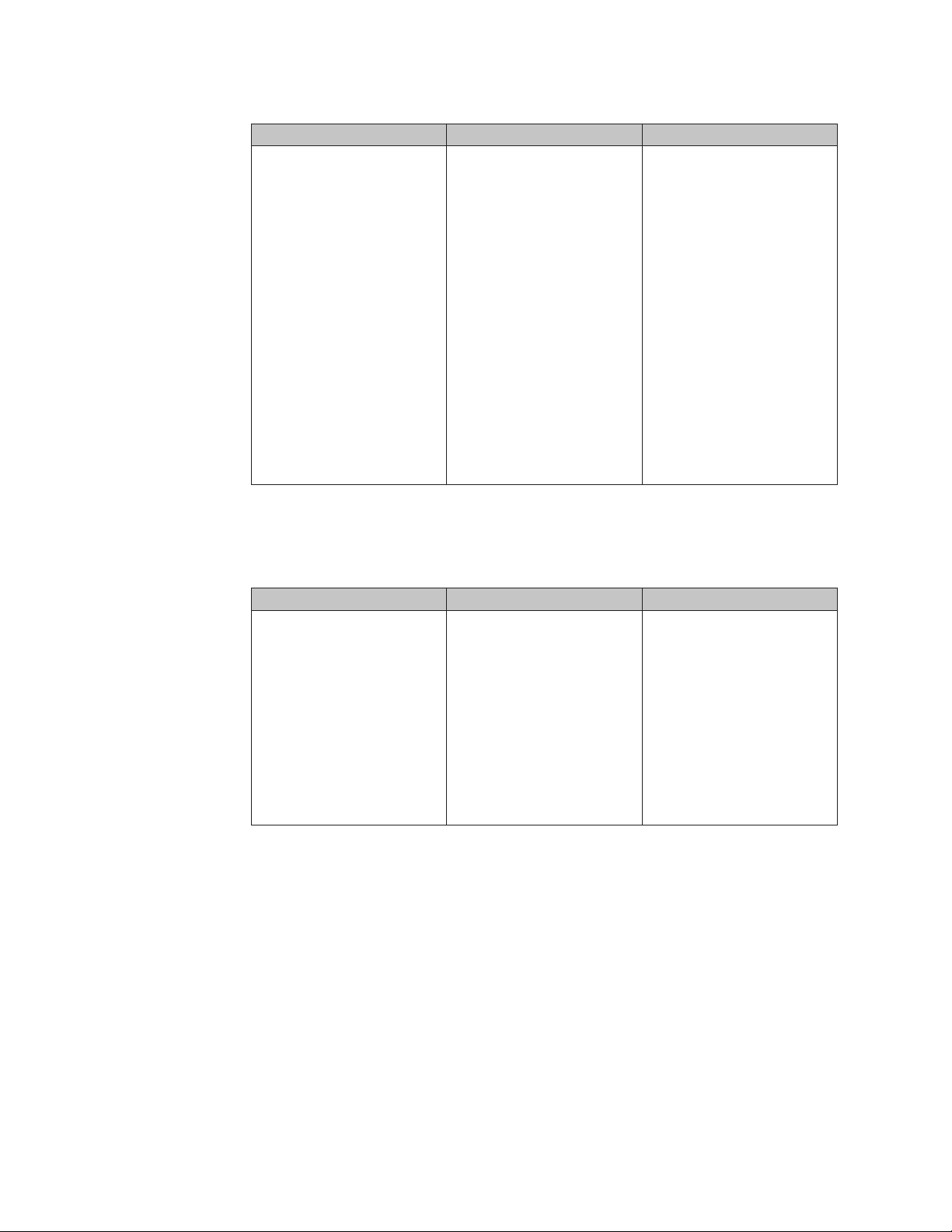
Table 2. Characteristics of a Portable-Sysprep Image
Description Advantages Disadvantages
v Semi-modular (supports
the installation of separate
application modules and
driver modules to append
the base image)
v Setup is run once on a
source computer
v Sysprep cleans out user
information and some
hardware-specific
information from the
registry
v Performs a limited
hardware query at the
target computer (Windows
Plug-n-Play function)
v User information can be
predefined
v Initial setup at the target
computer is typically 10
minutes or less for a base
image, plus the time it
takes to install all
applications
v Some portability (such as
video, audio, network, and
so on)
v Supports ThinkPad and
ThinkCentre computers
and other computers
v Base operating system
module can include some
large core applications
(such as office suites),
which speeds installation
time
v Image is used only for
identical or similar
hardware, and in most
cases is
manufacturer-unique.
The following table summarizes the characteristics associated with a
Hardware-Specific Image:
Table 3. Characteristics of a Hardware-Specific Image
Description Advantages Disadvantages
v Setup is run once at a
source computer
v Applications and drivers
are part of the base image
v Sysprep can be run to
clean out user information
v Initial setup at the target
machine is typically 10
minutes or less
v Images can be developed
for, deployed to, and
installed on ThinkPad,
ThinkCentre and other
computers, but each image
must be unique to a
specific hardware and
software configuration
v One image per hardware
platform
v Image is for use on
identical computers only
v Unique image must be
created for each set of
applications, or
applications must be
added manually after
installation
v No portability
10 ImageUltra Builder Version 3.1: User Guide
Page 25

Chapter 2. An overview of the image process
This chapter will help you understand the various processes and components
associated with the ImageUltra Builder program and how they relate to each other.
For step-by-step instructions on how to complete any of the processes described in
this chapter, refer to the ImageUltra Builder help system.
The ImageUltra Builder program stores individual image components as modules
in the ImageUltra Builder repository. A module is a packaged, compressed,
self-contained unit that often can be combined with other modules in the
repository to make one or more images. Each application is a module, each device
driver is a module, each operating system is a module, and so on.
Note: A module created from a Hardware-Specific Image cannot be combined with
any other modules to enhance its function. A module created from a
Portable-Sysprep image already contains device drivers and applications, but
can be combined with other application modules and device-driver modules
to enhance its function.
Modules fall into the following basic categories:
v Operating-system modules: There are three types of operating system modules:
– Base operating-system modules: These modules contain all of the components
that are part of the core operating system. Base-operating system modules can
be imported from the service partition or Hidden Protected Area (HPA) of a
source ThinkPad or ThinkCentre computer or can be created from any of the
following:
- Hardware-Specific Images
- Portable-Sysprep Images
- The I386 folder of a Windows installation CD
Note: The I386 base operating-system module is for use with
Ultra-Portable Images only. Whenever an I386 base operating-system
module is added to a base map, it must be accompanied by the
ImageUltra Customizations module and the appropriate primary
partitioning module (Win2000 Primary Partition, WinXP Home Primary
Partition, WinXP Pro Primary Partition or Tablet PC Partition) for the
operating system you are installing. An optional Sysprep module
may be used in conjunction with building an Ultra-Portable Image
for Windows XP and Windows 2000. If used, it needs to be placed in
the C:\SWWORK\SYSPREP folder.
If you want this I386 base operating-system module to install
unattended, you must also create an UNATTEND.TXT module and
include it in your base map. For more information about these
modules and for step-by-step instructions on preparing source files
and creating a module, see Chapter 8, “Preparing source files for
modules,” on page 135.
Base operating-system modules from Hardware-Specific Images and
Portable-Sysprep Images are typically created by and installed through an
imaging tool, such as Symantec Norton Ghost or PowerQuest DeployCenter.
Imported ImageUltra-developed base operating-system modules and base
© Lenovo 2005, 2006. Portions © IBM Corp. 2002, 2005. 11
Page 26

operating-system modules developed from the I386 folder (hereafter called
I386 base operating-system modules) go through a complete Windows
installation.
– Add-on operating system modules: These modules include items such as
operating-system hot fixes, service packs, patches, and updates that install
through a standard setup process, similar to applications.
– Partitioning modules: You use these modules to add one or more partitions
beyond the C partition, delete one or more pre-existing partitions, or create a
partition that can be used with I386 base operating-system modules. Yo u can
have multiple partitioning modules in a base map to accomplish various
results.
When you use a partitioning module to create additional partitions with data,
the module contains all of the information required to create the additional
partition and all of the data to be placed in the additional partition. These
types of partitioning modules are typically created using an imaging tool,
such as Symantec Norton Ghost or PowerQuest DeployCenter. If you just
want to add an empty data partition, you can create a simple batch file and
use it as the source file for your partitioning module.
For Hardware-Specific Images and Portable-Sysprep Images, you can set the
installation sequence to add or delete partitions before or after the new C
partition is installed. However, to add a partition after the C partition is
installed, you must have created your C partition to leave enough unused
disk space to accommodate the additional partition.
Ultra-Portable Images using imported ImageUltra-developed base
operating-system modules are typically limited to a single-partition
installation because they are designed to use all available disk space. If you
need to create one or more additional partitions, you must create a
partitioning module and set the installation sequence so the partitioning
module is installed before the base operating-system module.
Ultra-Portable Images using I386 base operating-system modules require that
you include the appropriate Primary Partition partitioning module for the
operating system you are installing. The Win2000 Primary Partition, WinXP
Pro Primary Partition, WinXP Home Primary Partition and Tablet PC Partition
modules are prebuilt partitioning modules provided as part of the ImageUltra
Builder program.
deployment and installation of operating-system modules are controlled by
The
base maps.
v Application modules: Each of these modules contains all of the components
associated with a specific application program.
– If you are building an Ultra-Portable Image or a Portable-Sysprep Image, you
can use application modules. The deployment and installation of the
applications modules are controlled by base maps.
– If you are building a Hardware-Specific Image, you cannot use application
modules in conjunction with that image. All applications must be part of the
Hardware-Specific Image.
Device-driver modules: Each of these modules contains all of the components
v
associated with a specific device driver.
– If you are building an Ultra-Portable Image or a Portable-Sysprep Image, you
can use device-driver modules. The deployment and installation of the
device-driver modules are controlled by driver maps.
12 ImageUltra Builder Version 3.1: User Guide
Page 27

– If you are building a Hardware-Specific Image, you cannot use device-driver
modules in conjunction with that image. All device drivers must be part of
the Hardware-Specific Image.
During
the deployment process, you choose which base map and which driver
map to deploy. This enables you to maintain device-driver modules and driver
maps independently of the operating-system and application content defined by
base maps.
In addition to modules, the ImageUltra Builder program enables you to create
containers in the repository. A container is a special type of module that enables
you to group other modules together under a single identifier. All modules in a
container must be of the same type. For example, you might want to group all of
the device drivers used for a specific machine type into a device-driver container.
Or, you might want to group a Windows 2000 base operating-system module with
all of its associated add-on modules into an operating-system container.
If you build an I386 base operating-system module, you might want to group the
I386 base operating-system module, the appropriate Primary Partition partitioning
module, the ImageUltra Customizations module, the Sysprep module, and the
UNATTEND.TXT module into a single operating-system container to ensure all
required components are kept together.
The use of containers is optional, but you might find containers helpful when
creating maps because you can simply insert the container module into your map
instead of inserting each individual module.
All maps and modules are stored in a repository. When the repository is viewed
through the ImageUltra Builder interface, the maps and modules are identified by
descriptive names. The actual file names are assigned by the ImageUltra Builder
program. The following is a list of file extensions used for the files in the
repository:
v .CRI: Metadata about the module. This information is used within the
ImageUltra Builder interface.
v .DMA: Driver maps
v .BMA: Base maps
v .IMZ: Compressed module source
The five basic steps to develop an image
There are five basic steps to developing an image:
1. Importing pre-existing modules
2. Building a module
3. Creating and modifying base maps and driver maps
4. Deploying Smart Images to target computers
5. Installing images on the target computer
remainder of this chapter provides details about these five basic steps.
The
Chapter 2. An overview of the image process 13
Page 28

Importing pre-existing maps and modules
The Import Wizard copies pre-existing maps and modules into your repository.
You can import maps and modules from any of the following sources:
v A service partition on a computer
v The Hidden Protected Area (HPA) on a ThinkPad or ThinkCentre computer
v A directory on a computer
v A different repository
v A set of ImageUltra Builder Distribution CDs or ThinkCentre and ThinkPad Recovery
CDs
v An ImageUltra export package
v A previous version of an ImageUltra repository
Importing maps and modules from a service partition or HPA
To import modules from a source computer, you must first install the ImageUltra
Builder program on the source computer and set up the source computer so it has
access to the your central repository. After the ImageUltra Program is installed,
open the ImageUltra Builder program, open the Repository window for your
central repository, then start and use the Import Wizard to import the desired
modules to your central repository.
The Import Wizard provides a categorized view of all application modules,
device-driver modules, filter modules, utility modules, base maps, and driver maps
that are in the source computer service partition or HPA. It enables you to select a
category and import all modules within that category, or select only those modules
or maps that you want to import.
In many cases, the operating-system modules are in a container and the entire
container must be imported. As part of the import operations, the Import Wizard
prompts you to select the folder in the repository where you want the maps and
modules to reside. You can use an existing folder in your repository, create a new
folder in your repository, or just put the imported modules in the root entry of
your repository.
The advantages of importing modules, as opposed to building your own, are as
follows:
v ImageUltra-developed modules have been tested by Lenovo and are ready for
deployment on ThinkPad and ThinkCentre computers.
v Base maps and driver maps are automatically created by the ImageUltra Builder
Import Wizard based on the modules you select to import. Yo u can use these
maps as they are, create new maps based on the maps created by the Import
Wizard and modify the maps to meet your particular needs, or discard the maps
and create your own maps.
v If base maps and driver maps already exist in the service partition of a source
computer, you can import those maps. Maps exist in a service partition only if
the source computer contains a Smart Image that was deployed by the
ImageUltra Builder program.
v ImageUltra-developed modules contain applications and signed device drivers
that conform to Microsoft certification requirements, ensuring device-driver
compatibility.
14 ImageUltra Builder Version 3.1: User Guide
Page 29

v Importing ImageUltra-developed modules from the service partition of a new
ThinkPad or ThinkCentre computer provides a streamlined path for creating
Ultra-Portable Images that can be used across the entire product line of
ThinkPad and ThinkCentre computers.
Importing maps and modules from repositories, folders, and CDs
In addition to importing from the service partition or HPA (as discussed in the
previous section), you also can use the Import Wizard from any ImageUltra
Builder console to import maps and modules from a folder, ImageUltra Builder
Distribution CD, ThinkCentre and ThinkPad Product Recovery CD, or a different
repository.
Note: You can order a set of Product Recovery CDs through your local customer
support center team. Alternatively, on most ThinkPad and ThinkCentre
personal computers, you can create your own set of Product Recovery CDs
using the Access ThinkVantage toolset.
v When importing from an ImageUltra Builder Distribution CD or a ThinkCentre and
ThinkPad Product Recovery CD, the Import Wizard provides a categorized view of
all the application modules, device-driver modules, filter modules, utility
modules, base maps, and driver maps that are available and enables you to
select all items in that category or select only those modules or maps that you
want to import. In most cases, the operating-system modules are in a container
and the entire container must be imported.
v When importing from a folder, the Import Wizard provides a categorized view
of all the operating-system modules, application modules, device-driver
modules, filter modules, utility modules, base maps, and driver maps that are
available and enables you to select all items in that category or select only those
modules or maps that you want to import.
v When importing from a different repository, you can choose to use either a
categorized view or a view of the entire repository as it is currently structured,
and select only those maps or modules that you want to import.
v You can also import from previous ImageUltra 2.x repositories. After selecting
the directory containing your 2.x repository, in the form of a Microsoft Access
Database file, choose either a categorized view or view the entire repository as it
is currently structure. Select only those maps or modules that you want to
import.
Building a module
In addition to importing modules, you can create your own modules for operating
systems, applications, and device drivers. However, there are a few limitations:
v Application modules and device-driver modules are for use in Ultra-Portable
Images and Portable-Sysprep Images only; they cannot be used in conjunction
with Hardware-Specific Images. Hardware-Specific Images must have all
required applications and device drivers installed on the source computer before
the image is created.
v Base operating-system modules can be created from Hardware-Specific Images,
Portable-Sysprep Images, or from the I386 folder of a Windows installation CD.
The base operating-system module created from an I386 folder (called an I386
base operating-system module) is for use with Ultra-Portable images only and must
be used in conjunction with the appropriate Primary Partition partitioning
module (Win 2000 Primary Partition, WinXP Home Primary Partition, WinXP Pro
Chapter 2. An overview of the image process 15
Page 30

Primary Partition or Tablet PC Primary Partition), ImageUltra Customizations
module, and the UNATTEND.TXT module.
Note: The Sysprep module can be used in conjunction with building an
Ultra-Portable Image for Windows XP and Windows 2000, and if used,
needs to be placed in the C:\SWWORK\SYSPREP folder. With ImageUltra 3.1,
however, the use of a Sysprep module in conjunction with an
Ultraportable Image is optional.
Optionally,
you can import ImageUltra-developed modules from the service
partition of a new ThinkPad or ThinkCentre personal computer. However,
imported ImageUltra-developed base operating system modules are limited to
deployment on ThinkPad or ThinkCentre personal computers only.
Building a driver module, application module, or add-on operating-system module
Preparing files for a device-driver module is different from preparing files for an
application module or an add-on operating-system module.
v Application files and add-on operating-system modules: In general, any
application or add-on operating-system component that you intend to use for a
module must have a silent-install capability for unattended installation. Before
you build a module, prepare the application or add-on operating-system
component for unattended installation so that the installation process does not
require any user interaction. In most cases, the Microsoft Software Installer (MSI)
and InstallShield programs allow for these types of automated installations.
The ImageUltra Builder program does make allowances for applications and
add-on operating-system components that do not allow for an unattended
installation. These types of application programs and add-on operating-system
components can be deployed as modules, but cannot be automatically installed.
Instead, you can have the ImageUltra Builder program copy the installable files
to the target computer and put an icon on the desktop that enables the user to
launch the setup program and install the program manually.
v Device-driver files: When building a device-driver module, you must use the
standard Microsoft Plug-n-Play.INF installation method, which is usually
unattended in nature. The device driver itself must be certified by the Microsoft
Windows Hardware Qualification Lab (WHQL) and signed. Failure to use
signed, WHQL-certified device drivers will result in interruptions during the
installation process because of Windows-generated information messages, which
require user interaction to bypass.
the application, add-on operating-system component, or device driver has
After
been prepared, use the New Module Wizard to create a module entry in the
repository and to set the attributes associated with the module. Attributes vary
depending on whether the module is a device-driver module, an application
module, or an add-on operating-system module. In all cases you must define a
name that will identify the module in the repository and the location where the
prepared files are currently stored. When you have finished defining the attributes,
you can select the entry from the repository and use the build tool to build the
module.
Note: The ImageUltra Builder program does not automatically scan files for
viruses. To help ensure a virus-free environment, use a virus-checking
program on the computer used to build the modules.
16 ImageUltra Builder Version 3.1: User Guide
Page 31

For step-by-step instructions on preparing source files and creating a module, see
Chapter 8, “Preparing source files for modules,” on page 135 or refer to the
ImageUltra Builder help system.
Creating a base operating-system module
If you choose to create your own base operating-system modules instead of
importing an ImageUltra-developed base operating-system module, you can do
any of the following:
v Build a module from an existing Hardware-Specific Image (an industry-standard
image created by Symantec Norton Ghost or PowerQuest DeployCenter).
v Create a Portable-Sysprep Image and build a module from it. When you create a
base operating-system module from a Portable-Sysprep Image, the module can
use application modules and device-driver modules to enhance its portability
across a wider range of hardware.
v Create an I386 base operating-system module for use in Ultra-Portable Images.
Creating a base operating-system module from a Hardware-Specific Image
A Hardware-Specific Image is a self-contained entity (operating system,
applications, and device drivers) that is prepared using the Microsoft Sysprep tool
and created using either Symantec Norton Ghost or PowerQuest DeployCenter. It
has limited portability because the source computer and target computer must use
identical hardware with very few variations. Many large companies are using
Hardware-Specific Images that can be converted to modules and deployed using
the ImageUltra Builder program.
Building an operating-system module from an existing Hardware-Specific Image is
simple. You use the New Module Wizard to create an operating-system module
entry in the repository and to set the attributes associated with the module. When
you have finished defining the attributes, you can select the entry from the
repository and use the build tool to build the module.
For step-by-step instructions on preparing source files for a Hardware-Specific
Image and creating a module, see Chapter 8, “Preparing source files for modules,”
on page 135 or refer to the ImageUltra Builder help system.
Creating a base operating-system module from a Portable-Sysprep Image
Creating a module from a Portable-Sysprep Image is nearly identical to creating a
module from a Hardware-Specific Image. The only difference is in the way you
create the Portable-Sysprep Image on the source computer.
By altering how the image is created, you can enable the image to append other
application programs and device drivers during the deployment and installation
process. The following are the alterations required to create a Portable-Sysprep
image.
Run the ImageUltra Customization Program (provided by the ImageUltra Builder
program) on the source computer before you run the Sysprep program. The
ImageUltra Customization Program provides the hooks required for Portable
Sysprep Images to make use of applications and device drivers defined in maps.
Most other aspects of developing a Portable-Sysprep Image are the same as
developing a traditional Hardware-Specific Image including running the Sysprep
tool and creating the image files using either Symantec Norton Ghost or
Chapter 2. An overview of the image process 17
Page 32

PowerQuest DeployCenter. Once you have created the image files, you use the
New Module Wizard to create an operating-system module entry in the repository
to set the attributes associated with the module. When you have finished defining
the attributes, you can select the entry from the repository and build the module.
For step-by-step instructions on building a Portable-Sysprep Image, see “Creating a
Portable-Sysprep Image” on page 142.
Creating an I386 base operating system module
An I386 base operating-system module is the central element of an Ultra-Portable
Image; however, when an I386 base operating-system is added to a base map, it
must be accompanied by the appropriate Primary Partition partitioning module
(Win2000 Primary Partition, WinXP Home Primary Partition, Win XP Pro Primary
Partition, or Tablet PC Primary Partition), the ImageUltra Customizations module,
the UNATTEND.TXT module, and optionally the Sysprep module . This section
provides an overview on how to create and implement these modules.
Note: The Sysprep module can be used in conjunction with building an
Ultra-Portable Image for Windows XP and Windows 2000, and if used,
needs to be placed in the C:\SWWORK\SYSPREP folder. With ImageUltra 3.1,
however, the use of a Sysprep module in conjunction with an Ultraportable
Image is optional.
The I386 base operating-system module contains all of the files and subfolders
contained in the I386 folder of a Windows installation CD. These files contain the
content and installation procedures associated with installing the operation system.
You must create an I386 base operating-system module for each operating system
you want to deploy as an Ultra-Portable Image. The only operating systems that
can be deployed as Ultra-Portable Images are:
v Windows XP Professional
v Windows XP Home
v Windows 2000
v Tablet PC
To build an I386 base operating-system module, you use the New Module Wizard
to create an operating-system module entry in the repository. When you have
finished defining the attributes, you can select the entry from the repository and
use the build tool to create the module. For more information on creating an I386
base operating system module, see “Preparing source files for an I386 base
operating-system module” on page 136.
The Primary Partition partitioning module is responsible for preparing the target
hard disk to accept a Windows installation. It creates the partition, formats the
partition, and establishes the partition as a bootable partition. Four Primary
Partition partitioning modules are provided as part of the ImageUltra Builder
program:
v The Win2000 Primary Partition partitioning module
v The WinXP Home Primary Partition partitioning module
v The WinXP Pro Primary Partition partitioning module
v The Tablet PC Primary Partition partitioning module
of these are ready-to-use operating-system partitioning modules. Yo u must
All
match the appropriate Primary Partition module with the I386 base
operating-system module.
18 ImageUltra Builder Version 3.1: User Guide
Page 33

The ImageUltra Customizations module contains the ImageUltra Customization
program, which provides the hooks required for the Ultra-Portable Images to make
use of applications and device drivers defined in maps. The ImageUltra
Customizations module is a ready-to-use operating-system module provided as
part of the ImageUltra Builder program, and is for use with I386 base
operating-system modules only. The ImageUltra Customizations module provided
as part of the ImageUltra Builder program is different from similarly named
modules that can be imported from source ThinkPad or ThinkCentre computers in
that it does not contain the Sysprep function.
Note: Do not attempt to use the ImageUltra Customizations module with
Portable-Sysprep Images or an Ultra-Portable Image developed from
imported ImageUltra-developed base operating-system modules. Also, some
imported ImageUltra-developed application modules might have a
dependency on the Sysprep function and might not install correctly when
used in images containing an I386 base operating-system module and an
ImageUltra Customizations module. If an imported ImageUltra-developed
application module does not install correctly, recreate the application module
using the ImageUltra Builder program.
The UNATTEND.TXT module is required if you want the image to be installed
unattended. This module enables you to replace the default UNATTEND.TXT file
contained in the I386 folder with one you create. This file enables you to predefine
values needed during the installation process, such as the product key, user name,
and company name. In some cases, you might want to create multiple
UNATTEND.TXT modules and let the person who will deploy the image select the
appropriate UNATTEND.TXT module.
To create this module, you must first create an UNATTEND.TXT file that contains
the values you want to use. Once you have created the UNATTEND.TXT file, you
use the New Module Wizard to create an operating-system module entry in the
repository and to set the attributes associated with the module. When you have
finished defining the attributes, you can select the entry from the repository and
build the module.
Creating a partitioning module
A partitioning module is a special type of operating-system module that is used for
several functions. You can use a partitioning module to delete one or more
partitions on a target computer before installing an image and to create additional
partitions, beyond the C partition. Yo u can have multiple partitioning modules in a
base map to achieve various results. Because an Ultra-Portable Image installation is
typically limited to a single-partition, you must create a partitioning module if you
intend to install an Ultra-Portable Image and need to have more than one user
partition on the target computer hard disk.
If you are installing a multiple-partition Portable-Sysprep Image or
Hardware-Specific Image, the use of a partitioning module for the creation of the
additional partitions is optional because the Symantec Norton Ghost and
PowerQuest DeployCenter tools enable you to capture multiple-partition images
from a source computer.
The advantage of using a partitioning module to create additional partitions is that
you can use your base map to select the appropriate data partition for the image
Chapter 2. An overview of the image process 19
Page 34

being installed. For example, if you are installing an image for an accounting
department, you can have a separate data partition that contains data specifically
for the accounting department.
To create a partitioning module that contains data, you must use either Symantec
Norton Ghost or PowerQuest DeployCenter to capture the partition from a source
computer and create the installation script for that partition. The installation script
defines the additional partition size and contents. Or, if you just want to create an
empty data partition, you can write a simple batch file and use it as the source file
for your partitioning module. In either case, you use the base map to define which
partitioning module to make available for installation, the conditions under which
it is to be installed, and module-installation order. You must install partitioning
modules before Ultra-Portable base operating-system modules. If you are using an
I386 base-operating system module for your Ultra-Portable Image, you must install
optional partitioning modules before the required Primary Partition partitioning
module.
Another use of a partitioning module is to preserve one or more pre-existing data
partitions on a target computer. The Image Ultra Builder program provides one
such partitioning module, named ImageUltra 3.1 - Drive Prep - Delete C Partition
Only. When this partitioning module is correctly implemented in a map, all
partitions on the target computer are preserved, except for the C partition. The
new image is then installed in the space previously used by the old C partition.
Several other partitioning modules are also provided as part of the ImageUltra
Builder program. See “Using a partitioning module in a base map” on page 96 for
more information.
Creating or modifying base maps and driver maps
To understand the importance and use of base maps and driver maps, you need to
have some insight into the deployment and installation processes.
If you are performing a standard network deployment using a service partition as
a staging area, the following takes place:
v The deployment process begins by starting the target computer from an
ImageUltra Builder Network Deployment CD or ImageUltra Builder Network
Deployment CD. During the deployment process, the person at the target
computer is prompted to select a base map and a driver map from the
repository. The modules that are defined in the selected base map and driver
map are deployed from the repository to the service partition of the target
computer.
v During the installation process, the person at the target computer is presented a
set of menus. The menu selections define the content of the image that will be
installed on the target computer. The menu items and menu hierarchy are
defined by menu-item entries in the base map. The physical appearance and
behavior of the menus are controlled by the properties assigned to the various
menu items. Based on the menu selections, the appropriate modules are
obtained from the service partition and unpacked on the C partition. Then, the
setup process begins.
you are performing a direct-network installation, the deployment and installation
If
are combined into a single operation as follows:
v The direct-network installation begins by starting the target computer from an
ImageUltra Builder Network Deployment CD or ImageUltra Builder Network
Deployment CD.
20 ImageUltra Builder Version 3.1: User Guide
Page 35

v The person at the target computer is prompted to select a base map and a driver
map from the repository.
v When the appropriate maps are selected, a network-staging folder is created on
the network for the target computer.
v Only those modules that are required to control the installation are copied to the
network-staging folder and unpacked.
v The person at the target computer is then presented with a set of menus. The
menu selections define the content of the image that will be installed on the
target computer. The menu items and menu hierarchy are defined by menu-item
entries in the base map. The physical appearance and behavior of the menus are
controlled by the properties assigned to the various menu items.
v Based on the menu selections, the appropriate modules are copied directly from
the repository to the C partition and unpacked. (Optionally, for console-side
recovery purposes, the entire Smart Image or the just the modules required for
the image being installed can also be copied to the service partition).
v Then, the setup process begins using the unpacked modules on the C partition.
you are performing an installation from an ImageUltra Builder Distribution CD,
If
the following takes place:
v The deployment process begins by starting the target computer from the
ImageUltra Builder Distribution CD. During the deployment process, the modules
that are defined in the base map and driver map on the CD are automatically
deployed from the CD to the service partition of the target computer.
Note: The service partition is always used as the staging area when doing an
installation from an ImageUltra Builder Distribution CD.
v During the installation process, the person at the target computer is presented
with a set of menus. The menu selections define the content of the image that
will be installed on the target computer. The menu items and menu hierarchy
are defined by menu-item entries in the base map. The physical appearance and
behavior of the menus are controlled by the properties assigned to the various
menu items. Based on the menu selections, the appropriate modules are copied
from the service partition to the C partition and unpacked. Then, the setup
process begins.
are three major parts to every map:
There
v The tree structure: A map tree structure is very similar to the tree structure
found in Windows Explorer; however, instead of containing files and folders, a
map tree structure contains menu items and modules, and possibly containers.
v Settings: Each map has a Settings window that enables you to control how a
map behaves. The Settings window for a base map also enables you to control
the physical appearance of the installation menus.
v Properties: The root entry of the tree structure and each menu item in the tree
structure has a set of properties. The properties associated with the root entry
and each menu item in a base map enable you to control the flow, the text of the
menu item, and the physical appearance and behavior of submenu items. These
properties also enable you to associate filters and utilities with menu items and
set conditions that control certain behavior on a menu-item by menu-item basis.
The menu-item properties for a driver map enable you to associate filters with
each menu item and set conditions that affect how the filters are used.
maps and driver maps have different purposes and use the tree structure,
Base
menu items, settings, and properties differently. Therefore, an individual overview
Chapter 2. An overview of the image process 21
Page 36

of each is provided in this section. For more detailed conceptual information about
maps, see Chapter 6, “Map construction overview,” on page 79. For step-by-step
information on creating and working with maps, see the ImageUltra Builder help
system.
Base maps
The tree structure in a base map enables you to define multi-tiered, multi-branch
structures containing a series of menu items that control the flow and content of
the menus displayed at the target computer during the installation process.
Modules are inserted in the map under menu items in strategic locations. As each
menu item is selected at the target computer, modules associated with that menu
item are collected. When the final menu item is selected from the last menu in the
sequence, all of the accumulated modules are installed.
You use the New Map Wizard to create a base-map entry in the repository. Then,
you populate the tree structure with menu items to establish the flow and content
of your menu system. Finally, you insert modules under menu items in strategic
locations to meet your particular needs. Optionally, you can change the overall
appearance of the menu system by modifying the properties associated with the
root entry of the tree structure. You can change colors, add window shadowing,
control navigation aids, and so on. For detailed information about constructing
base maps, see Chapter 6, “Map construction overview,” on page 79 and Chapter 7,
“Creating maps,” on page 117.
Driver maps
Driver maps are for use with Ultra-Portable Images and Portable-Sysprep Images
only; driver maps are not used by Hardware-Specific Images. If you select a driver
map in conjunction with a base map that contains a Hardware-Specific Image, the
driver map is ignored during the installation of the Hardware-Specific Image.
The tree structure in a driver map enables you to define a multi-branch structure
containing device-driver modules. The use of menu items is optional. Menu items
in a driver map serve two purposes only:
v They enable a developer to annotate or label groups of device-driver modules.
v They enable a developer to assign filters to one or more device-driver modules.
Using filters is optional, but they might be useful if you create a driver map that
contains device-driver modules for multiple computer types. The filters provided
with the ImageUltra Builder program enable you to key off of the machine type,
machine type and model, hardware platform (desktop or mobile), and whether
or not a computer is a ThinkPad or ThinkCentre computer.
items in driver maps have no effect on the menus displayed at the target
Menu
computer.
Use the New Map Wizard to create a driver-map entry in the repository. Then
populate the tree structure with menu items, if desired. Finally, insert modules in
your tree structure and optionally assign filters to menu items. For detailed
information about constructing driver maps, see Chapter 6, “Map construction
overview,” on page 79.
The use of driver maps is optional if the target computer is a ThinkPad or
ThinkCentre personal computer. If you do not select a driver map during the
22 ImageUltra Builder Version 3.1: User Guide
Page 37

deployment of an Ultra-Portable Image or a Portable-Sysprep Image, the
installation process will use the device-driver modules that are present in the target
computer service partition or HPA.
It is important to note that when a driver map is used with a ThinkPad or
ThinkCentre personal computer, the driver map does not append the
factory-installed device-driver modules; it deletes all factory-installed device-driver
modules and replaces them with the device-driver modules defined in the map.
Therefore:
v If you use a driver map with an Ultra-Portable Image, the driver map must
contain all device drivers required for the target computer.
v If you use a driver map with a Portable-Sysprep Image, the driver map must
contain all device drivers required to supplement those already contained in the
base operating-system module.
you develop an Ultra-Portable Image for computers that are not ThinkPad or
If
ThinkCentre computers, you must include one or more driver maps to support all
of the hardware configurations on which this image will be installed.
Defining the deployment and installation method
As you create your base map, the New Map Wizard enables you to define the type
of network installation to use. Yo u can choose:
v Direct-network installation: This method uses the network-staging folder to
control the installation. Modules are deployed and unpacked directly to the C
partition of the target computer.
v Network deployment with local installation: This method uses the service
partition as a staging area for the complete Smart Image.
You can also elect not to predefine an installation method and instead, prompt the
person at the target computer to select an installation method at the time of
deployment.
After you have used the New Map Wizard to create the map, you can change this
setting through the map Settings window. See “Specifying base-map settings” on
page 121 or the ImageUltra Builder help system for details.
Defining service-partition behavior
As you create your base map, the New Map Wizard enables you to define how the
ImageUltra Builder program uses the service partition on the target computer after
an image has been installed. Yo u have three options:
v Delete none:
– For a standard installation (network-deployment with local installation or
installation from CD), the service-partition size and contents remain the same
as when the Smart Image was deployed.
– For a direct-network installation, based on the map settings, a service
partition is created if one does not already exist. If a service partition does
already exist, it is resized if necessary, and the files in the service partition are
replaced with ImageUltra maps and modules.
The end result for either type of installation is that the service partition contains
the complete Smart Image.
v Delete some:
– For a standard installation (network-deployment with local installation or
installation from CD), all modules not used for this specific computer image
Chapter 2. An overview of the image process 23
Page 38

are deleted. The service partition is resized to accommodate only those
modules that remain. The C partition is resized to include any free space that
was created when the service partition was resized.
– For a direct-network installation, a service partition is created if one does not
already exist. If a service partition already exists, it is resized if necessary, and
any pre-existing maps and modules in the service partition are replaced with
the ImageUltra maps and modules required to recreate the installed image;
pre-existing utility files are not affected.
The end result for either type of installation is that the service partition contains
only those files required to recreate the image, and the service partition will not
be any larger than absolutely necessary to house those files. However, the
installation time is typically longer because of the time required to resize
partitions and move data.
v Delete all:
– For a standard installation (network deployment with local installation), the
service partition, which was used as a staging area for deployment, is deleted.
The C partition is resized to recover any free space that was created when the
service partition was deleted. The end result is no console-side recovery at the
target computer.
– For a direct-network installation, the behavior depends on whether or not a
service partition existed on the target computer before the direct-network
installation was initiated. If a service partition already existed on the target
computer before the direct-network installation took place, the service
partition is deleted and the C partition is resized to recover any free space
that was created when the service partition was deleted. If a service partition
did not exist before the installation, none was created, and no action is
required; and, in most cases the time required to do the overall deployment
and installation is substantially less than any other method. In either case, the
end result is no console-side recovery at the target computer.
can change the setting anytime during the map-development process through
You
the map Settings window. See “Controlling the behavior of the service partition”
on page 96 or the ImageUltra help system for details.
Enabling the network-sync function
The network-sync function is used to check the repository for updated maps. The
check will occur twice if the target computer is connected to the network:
v At the beginning of deployment: If a down-level map is selected, the
network-sync function will locate the latest map and use it in place of the
down-level map.
v At the beginning of installation: This check is most valuable when the
installation process takes place at a later date than the deployment process. In
this case, maps that have been updated or replaced since the original
deployment process took place are used. Depending on how much the map
content has changed since the original deployment, in some cases, this check
might result in the deployment of a complete, new Smart Image.
order for a network-sync operation to locate a replacement map, two conditions
In
must be met:
v The network-sync function must be enabled in the base map.
v The network-sync settings table (accessible through the ImageUltra Builder Tools
menu) must contain an entry defining the deployed map and the replacement
map.
24 ImageUltra Builder Version 3.1: User Guide
Page 39

As you create your base map, the New Map Wizard enables you to designate
whether you want to enable the network-sync function. You can change the
network-sync settings anytime during the map development process through the
map Settings window. See “Controlling the network-sync function” on page 95 or
the ImageUltra Builder help system for details.
Defining users and administrators
The new ImageUltra Administrator tool guides administrators through the process
of managing servers and users, and users and their access to repositories. The
Administrator tool secures repositories based on predetermined access levels set by
the administrator.
To help administrators manage and work with large numbers of users, the
ImageUltra Administrator provides tasks that organize and manage users
limitations and accessibility privileges to repositories and their contents. The
Administrator tool provides the following options to manage users and their access
to repositories:
v Administer users
v Change a user
v Create a new user
v Control users’ access to repositories
v Administer repositories
v Delete the repository
v Unlock a map or module within the repository
start the tool, click Tools in the Main window menu bar; then, click
To
Administration. Follow the instructions on the screen.
Defining user information
The User Information tab in base maps enables you to define default values for
user-specific settings, or prompt for user-specific settings near the beginning of the
installation process, or both. You can define the user information settings and
prompts anytime during the base-map development. For detailed information
about using this feature, see “Defining user information in a base map” on page
93.
If you are creating an Ultra-Portable Image using an I386 base operating-system
module, you must create an UNATTEND.TXT file to define certain user
information and control the operating-system installation. The UNATTEND.TXT
file is an answer file that resides in the I386 folder and contains all of the
information required by Windows setup. Although you can use the User
Information tab in the base maps to provide some of this information, it does not
provide all of the fields required for this type of installation. For information about
creating or modifying an UNATTEND.TXT file, use the following resources:
v The Microsoft Web site at
http://www.microsoft.com. Search for the string UNATTEND.TXT.
v Your Windows 2000 installation CD. Locate the UNATTEND.DOC file.
v Your Windows XP installation CD. Open the DEPLOY.CHM file located in the
DEPLOY.CAB file.
you create your UNATTEND.TXT file, you must create an UNATTEND.TXT
After
module and include it in your base map. During the image-installation process, the
UNATTEND.TXT module replaces the UNATTEND.TXT file in the I386 folder with
Chapter 2. An overview of the image process 25
Page 40

the UNATTEND.TXT file you created. This feature enables you to create multiple
UNATTEND.TXT files that can be associated with a common I386 base
operating-system module.
Deploying Smart Images to target computers
You can deploy Smart Images to target computers using either of two methods.
Important: Before deploying a Smart Image to a real work environment, test the
Smart Image to ensure that it works as expected.
Direct deployment from distribution discs
This method copies all modules defined in the selected base map and driver map
to a set of recordable CD or DVD discs.
The first CD of the set is bootable. When started in the target computer, the
deployment program on the disc copies the modules from the discs to the service
partition, and prepares the target computer for the installation process. If a service
partition does not exist at the start of the deployment process, one is created.
You use the ImageUltra Builder Deploy Wizard to create a set of stand-alone
Distribution discs. Based on your responses, the Deploy Wizard prompts you
through the steps required to create the discs. Typical steps include the following:
v Creating a Network Deployment CD
v Selecting the base map and driver map to be used
v Selecting the location of your recordable CD or DVD drive where the CD files
are to be stored
all required questions have been answered, the Deploy Wizard uses its
After
integrated disc-recording software to create your Deployment disc set.
You can also use the Deploy Wizard to do the following:
v Create ISO images that can be stored or made available to other locations
electronically
v Record discs from previously stored ISO images
v Copy raw files to folders so discs can be created using the third-party
disc-burning software of your choice
Note: Because disc 1 must be bootable, and uses specific files from the Network
Deployment CD, make sure you follow the instructions provided by the
Deploy Wizard and the ImageUltra Builder help system for creating
Distribution discs from files in folders.
Standard network deployment - network deployment with local installation
You use the ImageUltra Builder Deploy Wizard to create either an ImageUltra
Builder Network Deployment CD or an ImageUltra Builder Network Deployment disc on
recordable CD or DVD media. Based on your responses, the Deploy Wizard
prompts you through the steps required for creating the CD or DVD. Typical
information required to create the CD or DVD include the following:
v Path to the repository
v IP address (optional)
26 ImageUltra Builder Version 3.1: User Guide
Page 41

v User name
v Password (if required)
v Language and keyboard layout
v Keywords (allows only those maps with matching keywords to be selected from
the repository)
v Location of the drive where the media is to be recorded
Providing User name and password information on the deployment media
Note:
(CD, or DVD) is optional. If you do not provide a user name and password
when you create the deployment media, the person controlling the
deployment process will be prompted for this information (if it is required
to access the network) when the deployment media is started at the target
computer. If you do provide a user name and password when you create the
deployment media, it is stored in an encrypted format on the deployment
media.
If you choose to make a CD or DVD, in most cases you will use the disc-recording
software that is integrated into the ImageUltra Deploy Wizard, and the default
network device drivers provided by the ImageUltra Builder program to create the
CD or DVD. However, in some cases, you might need to create a customized
Network Deployment disc with special network device drivers. The ImageULtra
Deploy Wizard provides accommodations to make a customized Network Deployment
disc. You can use the Deploy Wizard to create a Network Deployment CD first and
modify the device drivers on it, or make your own boot CD with customized
drivers. Then, you use your disc-recording software of choice to create the CD or
DVD using the custom Network Deployment CD as source.
Note: Because this CD or DVD is bootable, make sure you follow the instructions
in the Deploy Wizard or ImageUltra Builder help system for creating a
custom Network Deployment disc.
To add device drivers to a deployment CD, do the following:
1. Determine where the device driver files need to go on the CD. That is, the .INI
file needs to go in the \i386\INF directory, and the device driver files need to
go in the \i386\system32\drivers directory.
2. Create a Drivers directory in the repository share directory.
3. In order to separate the NIC software, you need to create a folder for each NIC
device driver. For example, repositoryfilesshare\drivers\Broadcom,
repositoryfilesshare\drivers\Intel.
4. You then need to create a directory within the NIC folder and then place the
files in it.
Below are examples of pathnames to files copied into a repository:
<repositoryfilesshare>\Drivers\Broadcom\I386\inf\b57.inf
<repositoryfilesshare>\Drivers\Broadcom\I386\system32\drivers\b57.sys
<repositoryfilesshare>\Drivers\Broadcom\I386\system32\b57.dll
<repositoryfilesshare>\Drivers\Broadcom\I386\system32\b57.cat
<repositoryfilesshare>\Drivers\Broadcom\I386\system32\b57.din
Note: Every time you create a Network Deployment CD, the process will
automatically retrieve these files and place them on the deployment CD.
Chapter 2. An overview of the image process 27
Page 42

After the deployment CD is created the new files are found in the CD directories
below, where ’X’ is the letter of the CD drive:
X:\I386\inf\b57.inf
X:\I386\system32\drivers\b57.sys
X:\I386\system32\b57.dll
X:\I386\system32\b57.cat
X:\I386\system32\b57.din
Depending on the type of removable-media drive available at the target computer,
you use either the CD or DVD to establish a network connection between the
target computer and the ImageUltra module repository. After the connection is
established, you select which base map and driver map to use. All of the modules
defined in the map are downloaded to the service partition or HPA of the target
computer, and the target computer is prepared for the installation process. If a
service partition or HPA does not exist at the start of the deployment process, one
is created.
The advantages of CD or DVD deployment are speed and the flexibility of not
having to be dependent on a network connection. The advantage of network
deployment is the assurance that the latest maps and modules will be installed if
the network-sync function is enabled.
With the exception of a direct-network installation, the division between the
deployment and installation is a single boot cycle. In many cases, deployment is
done in one location and installation takes place in another location, typically at
the end-user’s work area. When deployment is complete, you can shut down the
target computer and prepare the computer for delivery to the end-user’s work
location.
Note: Some large enterprises that use drive-duplication technology for mass
production might want to replicate the drive at the end of the deployment
process, prior to installation. In order for this drive-duplication process to
work successfully, you must install the Boot Manager on each drive after the
drive has been duplicated. You can get the Boot Manager installation tool
(BMGRINST.BAT) from the TOOLS\BMGR folder of your repository. Yo u
must run BMGRINST.BAT during a Windows PE session.
Installing images on the target computer after deployment
In a standard network installation (network-deployment with local installation) or
an installation from an ImageUltra Distribution CD, the first boot cycle following the
end of deployment starts the installation process. The following sequence of events
takes place during the installation process.
1. An installation menu is displayed on the screen of the target computer. The
content and behavior of this menu is controlled by the base map. The person
performing the installation makes selections from the menu. The installation
program collects modules associated with the selected menu items until all
required modules are accumulated.
2. The accumulated operating-system modules and application modules are
decompressed and copied to the C partition.
3. The device-driver modules defined in the driver map are decompressed and
copied to the appropriate folder in the C partition.
4. Depending on the type of image you are installing, either a complete Windows
setup or Sysprep mini-setup operation begins. If you are installing an
28 ImageUltra Builder Version 3.1: User Guide
Page 43

Ultra-Portable Image, a full Windows setup operation begins. If you are
installing a Portable-Sysprep Image or a Hardware-Specific Image, a
Sysprep-controlled mini-setup operation begins.
Note: If you add user information to your base map, any prompts that you
defined take place near the beginning of setup. If you do not add user
information to your base map, prompts for specific user information
occur in the normal progression of the setup process. Not taking
advantage of the user-information feature might necessitate that an
installer be physically present at the target computer longer.
If you are installing an Ultra-Portable Image that uses an I386 base
operating-system module, the partitioning and formatting of the drive is
controlled by the primary partitioning module. The operating-system
installation and basic user settings are controlled by the
UNATTEND.TXT module and the ImageUltra Customizations module
prepares the image for installing application modules.
5. Upon the successful completion of the operating-system setup, the setup
process begins for each application program that was deployed as a module.
The installation order is determined by a combination of the following:
v The hooks and slots defined in the Options tab of attributes associated with
the module
v The Install Order tab of the base-map Settings window
For more information about the Install Hook and Install Slot module
Note:
attributes and the base-map Settings window, see Chapter 9, “Specifying
the module-installation order,” on page 167 or the ImageUltra Builder
help system.
6. When all applications have been installed, the installation process is complete.
If you specified in the base map that the service partition is to be deleted or
resized, the operation will take place at this time.
Performing a direct-network installation
A direct-network installation combines deployment and installation into one
seamless operation. Like a standard-network deployment, a direct-network
installation uses either a Network Deployment CD or a Network Deployment Disc (CD
or DVD) to begin the operation and select the desired base map and driver map.
However, the similarities stop there:
1. As soon as the base map and driver map are selected, the person controlling
the installation is immediately presented the installation menus and defines the
image to be installed. This allows all operator intervention to be performed up
front before any modules are copied.
2. After the menu selections have been made to define the image, a temporary
network-staging folder is created on the network. Only those modules required
to control the installation are unpacked to this folder.
3. All remaining modules that make up the defined image content are unpacked
directly to the target computer C partition. Optionally, if console-side recovery
is desired, and the base-map settings are set correctly, the complete Smart
Image (or only those files required to recreate the image being installed) can be
copied to the service partition.
4. Depending on the type of image being installed, either a complete Windows
setup or a Sysprep mini-setup operation begins.
Chapter 2. An overview of the image process 29
Page 44

Note: If you add user information to your base map, any prompts that you
defined take place near the beginning of setup. If you do not add user
information to your base map, prompts for specific user information
occur in the normal progression of the setup process. Not taking
advantage of the user-information feature might necessitate that an
installer be physically present at the target computer longer.
If you are installing an Ultra-Portable Image that uses an I386 base
operating-system module, the partitioning and formatting of the drive is
controlled by the primary partitioning module. The operating-system
installation and basic user settings are controlled by the
UNATTEND.TXT module and the ImageUltra Customizations module
prepares the image for installing application modules.
5. Upon the successful completion of the operating-system setup, the setup
process begins for each application program that was deployed as a module.
The installation order is determined by a combination of the following:
v The hooks and slots defined in the Options tab of attributes associated with
the module
v The Install Order tab of the base-map Settings window
For more information about the Install Hook and Install Slot module
Note:
attributes and the base-map Settings window, see Chapter 9, “Specifying
the module-installation order,” on page 167 or the ImageUltra Builder
help system.
6. When all applications have been installed, the installation process is complete.
If you specified in the base map that the service partition is to be resized or
deleted, the operation will take place at this time.
Advanced functions
There are two optional, advanced functions that you can use to enhance the image
process: filters and utilities.
Filters
Filters automate a decision during the installation process. You typically use filters
to obtain hardware-related information from a target computer to determine if a
specific module or set of modules should be installed. The ImageUltra Builder
program provides filters that check the machine type, machine type and model
number, hardware platform (mobile or desktop), and whether or not a computer is
a ThinkPad or ThinkCentre computer. You can also develop your own filters if
needed.
Filters are Win32-based programs that run during the installation process. In most
cases filters query the BIOS of the target computer, but they can query other
devices that store identification information in a ROM or EEPROM module. For
example, you might want to check for the presence of a PCI modem before
installing a modem-related application program or you might want to check for a
specific machine type to determine which device drivers should be installed.
You can implement filters two different ways:
v Assign a filter to a menu item in either a base map or driver map by using the
Filter tab attributes for the menu item.
v Assign a filter directly to an application or device-driver module by using the
Filter-tab attributes for that specific module.
30 ImageUltra Builder Version 3.1: User Guide
Page 45

Using filters enables you to develop one map that works across many computer
types. For information about creating your own filters or information about using
the filters provided with the ImageUltra Builder program, refer to the ImageUltra
Builder help system.
Utilities
Utilities are Win32-based EXE, BAT, or COM files that run during the installation
process. For example, an installer might want to run CHKDSK to determine the
size and condition of a hard disk before any files get installed. Utilities are copied
to the service partition of the target computer during deployment, run during the
installation process, but never get copied to the active partition of the target
computer.
You can incorporate utilities in a map to run immediately before the installation
menus, immediately after the installation menus, or as a result of a selection in the
installation menus. You determine how the utilities run and the order in which
they run.
The ImageUltra Builder program does not provide any utilities. If you want to
include utilities, you will have to build your own utility modules.
To use a utility, you either assign a utility module to a base-map menu item or use
the Before/After Menu tab in the Map Settings window for base maps.
For information about creating your own utilities, see Chapter 8, “Preparing source
files for modules,” on page 135. For more information about maps, see Chapter 6,
“Map construction overview,” on page 79 and Chapter 7, “Creating maps,” on
page 117.
Chapter 2. An overview of the image process 31
Page 46

32 ImageUltra Builder Version 3.1: User Guide
Page 47

Chapter 3. Staging-area behavior and logic
As discussed in Chapter 1, “ImageUltra Builder capabilities,” on page 1, the
ImageUltra Builder program can use two different staging areas for deployment:
v The service partition
v The network-staging folder
In addition, some ThinkPad and ThinkCentre computers use a Hidden Protected
Area (HPA) to store factory images, utilities, and diagnostic programs for recovery
purposes. Although the ImageUltra Builder program does not deploy images to an
HPA, there are some relationships during the deployment phase and after
installation of which you might need to be aware. Also, the ImageUltra Builder
program does have the ability to import modules from an HPA.
This chapter provides additional details about these staging areas and how the
ImageUltra Builder program interacts with them.
Staging areas details
The information in this section provides details about the two staging areas used
by the ImageUltra Builder program
The service partition
The service partition (volume label SERVICEV001) is a hidden partition on the
hard disk that typically contains operating-system modules, application modules,
device-driver modules and a set of recovery tools. It also provides its own
operating environment, which has no dependency on the Windows operating
system being functional or present on any active partition. Because the service
partition is protected from common read and write operations, as well as most
viruses, it is a practical place to store recovery, backup, and installation files and
tools.
The service partition has three major purposes:
v As shipped from the factory on many older ThinkPad, NetVista, and
ThinkCentre models, the service partition provides a DOS-based recovery
mechanism to restore the contents of the hard disk to its factory-installed state
without requiring a Windows CD or a set of ThinkCentre or ThinkPad Product
Recovery CDs. The factory-installed service partition also provides a vehicle for
distributing modules associated with the preinstalled software that the
ImageUltra Builder program can import.
v As used by the factory-installed version of the ThinkVantage Rescue and Recovery
product, the service partition contains its own operating environment (Windows
PE) that runs independently of the Windows operating system on the C
partition, a set of tools to help diagnose problems, and a set of tools to help you
restore the contents of the hard disk to its factory-installed state or to one of
several backed-up states. The backup and restore functions are integrated into
the Rescue and Recovery product. Backup operations are from a Rescue and
Recovery utility that runs in the Windows environment only. Backup files can be
stored in a virtual partition located on the C drive, on an additional local drive,
on a CD or DVD, or on a network drive, but not in the physical service
partition. Restore or recovery operations can be run from either the Rescue and
© Lenovo 2005, 2006. Portions © IBM Corp. 2002, 2005. 33
Page 48

Recovery utility that runs in the Windows environment, or the Rescue and
Recovery Workspace that runs from the physical partition. The factory-installed
recovery image is always stored in the physical service partition. The physical
service partition also contains modules associated with the preinstalled software
that the ImageUltra program can import.
Note: The Rescue and Recovery product is a standard feature on many new
ThinkPad and ThinkCentre models. It is also available as a download for
some other ThinkPad and ThinkCentre models at http://www.lenovo.com/
think/support/
site.wss/MIGR-4Q2QAK.html, and is available as a retail product for some
computers that are not ThinkPad or ThinkCentre computers. The
factory-installed version uses a physical service partition for the operating
environment and tools as described in this section. The user-installable
versions typically use a virtual partition located on the C drive for their
operating environment and tools.
v As used by the ImageUltra Builder program, the service partition is a storage area
for deployed Smart Images and for the tools required to perform the
image-installation process.
When a Smart Image is deployed to a target computer that has a
factory-installed Windows PE-based service partition, the Smart Image replaces
the factory-installed image files (modules) with its own maps and modules. All
other components are left intact.
When a Smart Image is deployed to a target computer that has a DOS-based
service partition, the ImageUltra Builder program replaces the entire DOS-based
service partition with its own Windows PE-based service partition and tools.
If a service partition does not exist on a target computer before a Smart Image is
deployed, the ImageUltra Builder program creates a Windows PE-based service
partition for Smart Images that are deployed through the standard
network-deployment process or from ImageUltra Distribution Discs. For Smart
Images that are deployed through a direct-network installation process, the
creation of a service partition is optional.
After a Smart Image has been deployed to the service partition and the image
installed to the primary partition, the ImageUltra Builder program can deal with
the Smart Image files in the service partition in one of three ways:
– Leave the entire Smart Image intact
– Delete all modules not used for the installed image
– Delete the entire Smart Image
With the latter two options, the service partition is resized or eliminated and the
primary partition is resized to recover any unused space. For additional
information about these settings, see “Base-map settings” on page 69 and look
for the information about the Image Cleanup tab.
Access to the service partition is controlled by a boot-manager program.
The network-staging folder
The network-staging folder has one purpose; during a direct-network installation,
it provides a temporary storage area on the network to unpack the modules and
the maps that control the installation of the image. By default, a separate
network-staging folder is created for each target computer in the NETDEPL folder
located under the repository being used. The name assigned to the network
staging folder is based on the last 11 characters of the target computer MAC
address.
34 ImageUltra Builder Version 3.1: User Guide
Page 49

Note: If necessary, you can define a location outside of the repository where the
network-staging folders will be created. See “Controlling write-access to
repository during direct-network install” on page 181 for more information.
Unlike deployment to a service partition, the person at the target computer who is
controlling the direct-network deployment makes choices from the installation
menu system before any modules are sent to the target computer. Then, only those
modules required for the selected image are obtained from the repository,
unpacked dynamically, and installed on the target computer. The target computer
must remain connected to the network throughout the entire deployment and
installation process. When the installation process is complete, the network-staging
folder is automatically erased.
A direct-network deployment does not require that a service partition be present
on the target computer. The use of a service partition is optional, and if used, its
only purpose is to store maps and modules for client-side recovery. A service
partition is not used as a staging area during a direct-network installation process.
v If you do not want maps and modules copied to a service partition, you
minimize the deployment time, but you will not have client-side recovery for the
image you deployed.
v If you want only those maps and modules that are required to recreate the
installed image copied to a service partition, deployment time will be longer, but
you will have client-side recovery for the specific image that is installed on the
target computer.
v If you want the complete Smart Image copied to a service partition, deployment
time will be longer yet, but you will have client-side recovery for any of the
images that can be installed from the Smart Image.
For additional information about these settings, see “Base-map settings” on page
69, and look for the information about the Image Cleanup tab.
Chapter 3. Staging-area behavior and logic 35
Page 50

Deployment and installation overview
This section provides an overview of the various deployment and installation
processes.
Standard network-deployment process with local installation
The following illustration shows the standard network-deployment process with
local installation. Notice that the service partition is used as the staging area for all
maps and modules required for the Smart Image.
Repository
Deployment
1
Select
base map
and driver map
Smart image
on Staging area
(service partition)
2
Copy
3
Make menu
selections to
define the
image to be
installed
Installation
C partition
5
4
S
e
t
u
p
Smart Image
on service
partition
Final image
on C partition
1. The person controlling the deployment starts the process by booting the target
computer with an ImageUltra Builder Deployment Disc (CD or DVD) or an
ImageUltra Builder Deployment CD, and then selecting the required maps from
the repository.
2. The selected maps and all modules defined within the maps are obtained from
the repository and copied over the network to the service partition, which acts
as the staging area for the complete Smart Image.
Note: At this point, a message is displayed stating that the deployment phase
is complete. The person controlling the deployment can either shut down
the computer at this point and ship it to another location, or continue
with the installation phase.
3. The person controlling the installation process, starts the installation phase by
making selections from the installation menus to define the image to be
installed.
4. The modules required for the defined image are unpacked from the service
partition onto the C partition.
5. The setup process begins. When the installation phase is over, the C partition
contains the new image and the service partition contains the Smart Image,
which can be used for client-side recovery.
Note: An optional cleanup step can be defined in the base map Map Settings
window to minimize the size of the service partition and keep only those
files required for the installed image, or eliminate the service partition.
36 ImageUltra Builder Version 3.1: User Guide
Page 51
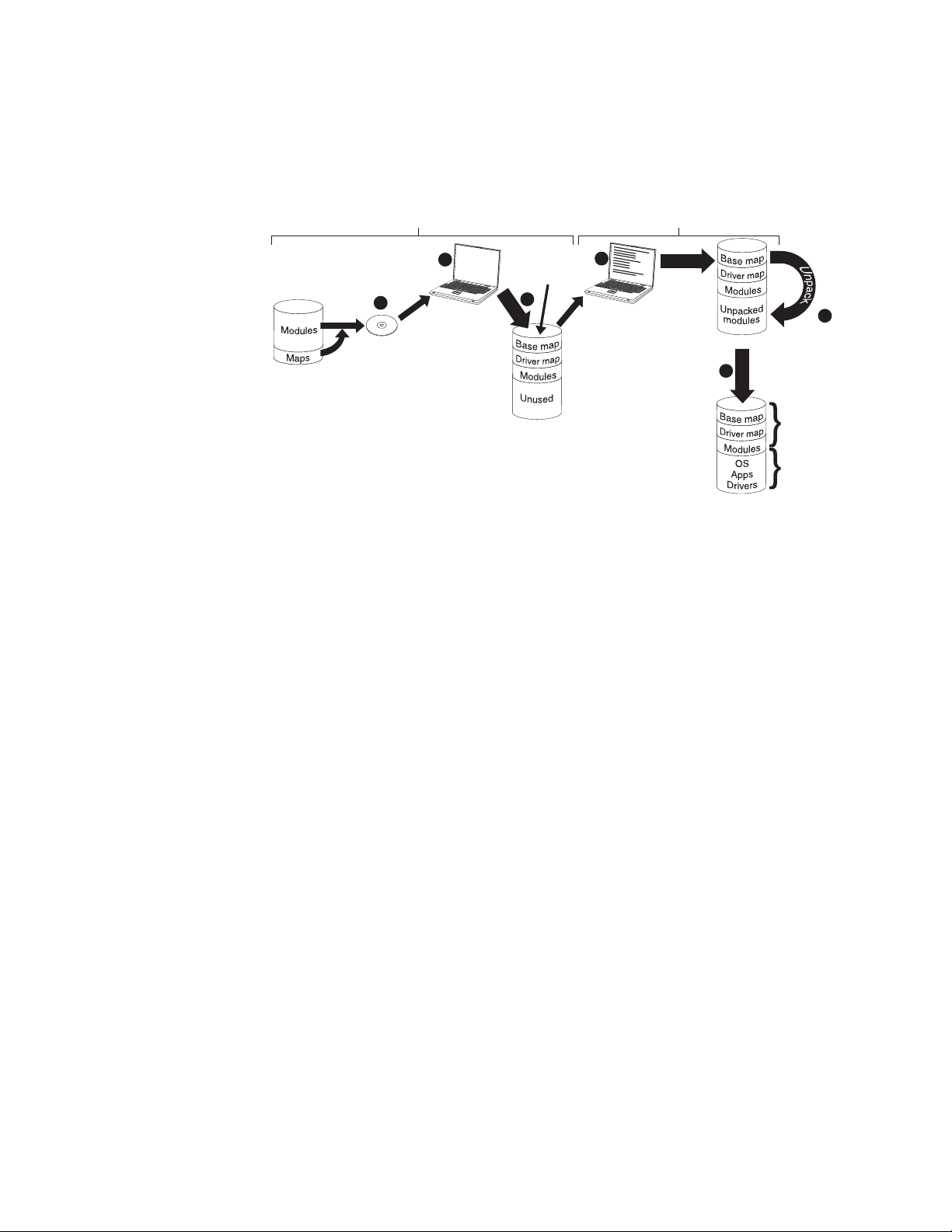
CD or DVD distribution
The following illustration shows the deployment process using an Image Ultra
Builder Distribution Disc (CD or DVD) and a local-installation process, which uses a
service partition as a staging area.
Repository
Deployment
1
Create
distribution
CD
2
Start target
computer with
distribution CD
Smart image
on Staging area
(service partition)
Copy
3
4
Make menu
selections to
define the
image to be
installed
Installation
C partition
S
e
t
6
u
p
5
Smart Image
on service
partition
Final image
on C partition
1. The first step in CD or DVD deployment is the creation of a set of ImageUltra
Builder Distribution Discs. (See the ImageUltra Builder help system for details).
2. The person controlling the deployment starts the process by booting the target
computer with an ImageUltra Builder Distribution Disc.
3. The maps and modules contained on the set of discs are copied to the service
partition, which acts as the staging area for the complete Smart Image.
Note: At this point, a message is displayed stating that the deployment phase
is complete. The person controlling the deployment can either shut down
the computer at this point and ship it to another location, or continue
with the installation phase.
4. The person controlling the installation process, starts the installation phase by
making selections from the installation menus to define the image to be
installed.
5. The modules required for the defined image are unpacked from the service
partition onto the C partition.
6. The setup process begins. When the installation phase is over, the C partition
contains the new image and the service partition contains the Smart Image,
which can be used for client-side recovery.
Note: An optional cleanup step can be defined in the base map Map Settings
window to minimize the size of the service partition and keep only those
files required for the installed image, or eliminate the service partition.
Direct-network installation
The following illustration shows a direct-network installation, which uses a
network-staging folder as a staging area.
Chapter 3. Staging-area behavior and logic 37
Page 52

(Optional)
Smart Image
or copy of
installed image
Final image
on C partition
Repository
1
Select
base map
and driver map
Unpack
Unpack
required
modules
2
(Network-staging
Copy (optional)
Staging area
folder)
Unpack
3
Setup
4
Make menu
selections to
define the
image to be
installed
1. The person controlling the direct-network installation starts the process by
booting the target computer with an ImageUltra Builder Deployment Disc (CD or
DVD) or an ImageUltra Builder Deployment CD, and then selects the required
maps from the repository.
2. A network-staging folder is created specifically for the target computer. The
selected maps and a limited number of modules (only those required to control
the installation process) are copied to the network-staging folder, which acts as
a staging area for the installation process.
3. The person controlling the direct-network installation makes selections from the
installation menus to define the image to be installed.
4. The modules required for the defined image are obtained directly from the
repository and copied over the network to target computer C partition. Then,
the setup process begins.
Note: Optionally, if a developer of the image specified that a service partition
is to be created for client-side recovery purposes, the maps and modules
also are copied to a service partition.
When setup is complete, the C partition contains the new image.
ImageUltra Builder relationships with the Hidden Protected Area (HPA)
This section provides information about the purpose of the Hidden Protected Area
(HPA) and the relationships that exist between the HPA and the ImageUltra
Builder program. Additional information about the HPA is available from the
Lenovo Web site at:
http://www.lenovo.com/think/support/site.wss/document.do?lndocid=MIGR-46023
What is a Hidden Protected Area?
Implemented in 2003 on selected models of ThinkPad and ThinkCentre computers,
the Hidden Protected Area (HPA) is a variant in the IBM disk-to-disk recovery
scheme. Like the service partition, the HPA provides its own operating
environment and contains operating-system modules, application modules,
device-driver modules, and a set of recovery tools. But, the similarities stop there.
The architecture of the HPA provides a secure environment. Protection settings
(security levels) and access to the HPA are controlled by the computer basic
input/output system (BIOS). The HPA does not rely on a boot manager, and is
therefore immune from boot-sector viruses, which could cripple other disk-to-disk
recovery methods.
Each application within the HPA is contained on its own protected service area
(PSA). There are two types of PSAs: Boot PSAs and Data PSAs. Boot PSAs contain
all of the files necessary to boot and start the application from the associated Data
38 ImageUltra Builder Version 3.1: User Guide
Page 53

PSA and to display an icon on a secure launching area called the Access IBM
Predesktop Area. Each Boot PSA is digitally signed to deter tampering and to deter
viruses. Each time a Boot PSA is used, the signature is checked. Only those PSAs
with valid signatures are permitted to boot. Data PSAs contain all of the files
associated with the application itself.
On some ThinkCentre and ThinkPad models, the HPA provides the tools to
diagnose a problem and recover from a catastrophic failure by restoring the
contents of the hard disk to a factory-installed state. Access to these tools is
provided through the IBM Predesktop Area.
Recovery impacts
Because the content of the HPA is not affected by the ImageUltra Builder
deployment or installation processes, it is very likely that you can have multiple
forms of recovery after a Smart Image has been installed on a target computer that
has an HPA. The presence or absence of the Rescue and Recovery product also has
an impact on recovery options.
Because the tools within the HPA are DOS based and the HPA is protected against
alterations, when the ImageUltra Builder program is installed on a computer that
has an HPA, the ImageUltra Builder program creates its own service partition and
installs a boot manager to bypass the IBM Predesktop Area. When F11 is pressed
during startup, instead of booting to the IBM Predesktop Area, the computer boots
to service partition and opens the ThinkVantage ImageUltra Builder workspace. All
recovery operations are performed from the ThinkVantage ImageUltra Builder
workspace.
If a user selects Restore your system --> Restore my hard drive to the original
factory state from the ThinkVantage ImageUltra Builder workspace menu, the
ImageUltra Builder installation menu system opens, which enables the user to
reinstall the Smart Image instead of the original factory-installed image.
Importing modules and maps from an HPA
The ImageUltra Builder program can import modules and maps from an HPA just
like it does from a service partition. For more information about importing
modules, see “Importing pre-existing maps and modules” on page 14.
Using drivers in an HPA
Because the contents of an HPA are preserved while a Smart Image is being
installed, the ImageUltra Builder program can use the device drivers stored in the
HPA if a driver map is not defined for the Smart Image. See “Using drivers in an
HPA” for more information.
ImageUltra Builder relationships with the Rescue and Recovery product
This section provides information about the Rescue and Recovery product and the
relationships that exist between the Rescue and Recovery product and the
ImageUltra Builder program.
What is the Rescue and Recovery product?
The Rescue and Recovery product provides a set of tools to help users diagnose,
get help, and recover from a system failure even if the Windows operating system
on the C partition cannot be started. The Rescue and Recovery product is available
as follows:
Chapter 3. Staging-area behavior and logic 39
Page 54

v As a standard, preinstalled feature on many ThinkPad and ThinkCentre
computers manufactured since 2003.
v As a retail product for some computers that are not ThinkPad or ThinkCentre
computers
v As a downloadable product for selected ThinkPad and ThinkCentre computers
from:
http://www.ibm.com/pc/support/site.wss/MIGR-4Q2QAK.html
The Rescue and Recovery tools reside in two locations:
v On the Windows side (C partition) are a set of tools that enable a user to create
backups, rescue media, and recovery media.
v In a Windows PE-based partition is the Rescue and Recovery workspace, an
environment that runs independently of the Windows operating system and is
hidden from the Windows operating system.
Because the Rescue and Recovery workspace is hidden, it is immune from most
types of virus attacks and provides a safe place from which to perform rescue
and recovery operations that might not be possible in the Windows
environment.
factory-installed version of the Rescue and Recovery product uses a service
The
partition. The user-installable versions of the Rescue and Recovery product
typically installs in and uses a virtual partition. However, if the user-installable
versions of the Rescue and Recovery products detect a pre-existing Windows
PE-based service partition with at least 500MB of free space during the installation,
it will install in and use the service partition.
Impacts
As of the publishing of this book, there are three versions of the Rescue and
Recovery program:
v Rescue and Recovery with Rapid Restore (referred to as Rescue and Recovery
version 1)
v Rescue and Recovery - Rapid Restore (referred to as Rescue and Recovery
version 2)
v Rescue and Recovery 3 (referred to as Rescue and Recovery version 3)
Because
version and the ImageUltra Builder program vary.
The following scenarios are provided to help you understand the relationship
between the ImageUltra Builder program and the various versions of the Rescue
and Recovery product.
v Scenario 1: Installing Rescue and Recovery version 3 on a computer that has a
of the variations among these versions, the relationship between each
Smart Image installed. In this scenario, if a service partition already exists, the
content of the service partition will remain mostly unchanged. The name of the
ThinkVantage ImageUltra Builder workspace will change to the Rescue and
Recovery workspace and the list of menu items might be extended to provide
more recovery options.
If a service partition does not already exist, the Rescue and Recovery version 3
program will be installed in a virtual partition.
Additionally, whether or not a service partition already exists, several additional
Rescue and Recovery tools will be installed on the C partition and added to the
Windows Start menu.
40 ImageUltra Builder Version 3.1: User Guide
Page 55

v Scenario 2: Installing Rescue and Recovery versions 1 or 2 on a computer that
has a Smart Image installed. This scenario is not supported if a service partition
already exists. If a service partition does not already exist, the Rescue and
Recovery version 1 or 2 program will be installed in a virtual partition and
several additional Rescue and Recovery tools will be installed on the C partition
and added to the Windows Start menu.
v Scenario 3: Installing a Smart Image on a target computer that has a service
partition containing the Rescue and Recovery version 1 or 2 program. In this
scenario, only the maps and modules in the service partition get replaced. No
other modifications are made to the service partition contents.
Security dependencies
The ImageUltra Builder program is able to use the device-driver modules from the
HPA during deployment if a driver map is not used. However, in order to do so,
the HPA security settings in the target computer BIOS settings must be set to either
High security or Medium security. If the security setting is set to Security
disabled, the ImageUltra Builder program does not attempt to use the
device-driver modules from the HPA; instead, it will check to see if a service
partition exists and attempt to use the device-driver modules from the service
partition.
On computers that are not HPA-enabled, there are no corresponding BIOS security
settings. If a Smart Image is deployed without a driver map, the ImageUltra
Builder program always attempts to use the device drivers from the service
partition.
Staging-area logic
Because various conditions might exist on different target computers, the
ImageUltra Builder program uses built-in logic to ensure that a common Smart
Image can be used across a wide range of computers. Varying conditions include:
v Support or the lack of support for an HPA in the BIOS
v The presence or absence of an HPA
v The presence or absence of a service partition
The following table shows how the deployment behavior changes on a ThinkPad
or ThinkCentre computer based on conditions that exist before the image is
deployed.
Notes:
1. The use of driver maps and the use of device driver modules from either the
2. You also can use the following table to determine the behavior for a
service partition or HPA is limited to Portable-Sysprep Images and
Ultra-Portable Images.
direct-network install that specifies the use of a service partition for
console-side recovery purposes.
Chapter 3. Staging-area behavior and logic 41
Page 56

Table 4. Staging-area behavior - ThinkPad and ThinkCentre computers
Conditions on a ThinkPad or ThinkCentre
target computer prior to deployment
HPA present
with security
Maps
deployed
Base map and
driver map
settings set to
HPA support
in BIOS
Medium or
High
Yes No Yes
Service
partition
present Result from deployment
v Create the service
partition.
v Deploy the Smart Image
as defined in base and
driver maps to the
service partition.
Base map and
driver map
No No No
v Create the service
partition.
v Deploy the Smart Image
as defined in the base
and driver maps to the
service partition.
Base map and
driver map
Yes Yes No
v Create the service
partition.
v Deploy the Smart Image
as defined in the base
and driver maps to the
service partition.
Base map and
driver map
Yes No No
v Delete all unnecessary
modules and files from
the service partition.
Preserve any Rapid
Restore files or Rescue
and Recovery files that
might exist.
v Resize the service
partition, if required.
v Deploy the Smart Image
as defined by the base
and driver maps to the
service partition.
Base map
only
Yes No Yes
v Create the service
partition.
v Deploy all modules
defined in the base map
to the service partition.
Note:
not used under these
conditions, setup will use
the native Windows device
drivers and some features
might not be enabled or
optimized.
If a driver map is
42 ImageUltra Builder Version 3.1: User Guide
Page 57

Table 4. Staging-area behavior - ThinkPad and ThinkCentre computers (continued)
Conditions on a ThinkPad or ThinkCentre
target computer prior to deployment
HPA present
with security
Maps
deployed
Base map
only
settings set to
HPA support
in BIOS
Medium or
High
No No No
Service
partition
present Result from deployment
v Create the service
partition.
v Deploy all modules
defined in the base map
to the service partition.
If a driver map is
Note:
not used under these
conditions, setup will use
the native Windows device
drivers and some features
might not be enabled or
optimized.
Base map
only
Yes Yes No
v Create the service
partition.
v Deploy all modules
defined in the base map
to the service partition.
v Use device-driver
modules from the HPA
and use them during
installation.
Base map
only
Yes No Yes
v Delete all unnecessary
modules and files from
the service partition.
Preserve any Rescue and
Recovery files that might
exist.
v Resize the service
partition, if required.
v Deploy the Smart Image
as defined by the base
map to the service
partition.
v Use device-driver
modules that are
currently in the service
partition.
If a driver map is
Note:
not used under these
conditions, and no device
drivers are in the existing
service partition, setup will
use the native Windows
device drivers and some
features might not be
enabled or optimized.
Chapter 3. Staging-area behavior and logic 43
Page 58

Table 4. Staging-area behavior - ThinkPad and ThinkCentre computers (continued)
Conditions on a ThinkPad or ThinkCentre
target computer prior to deployment
HPA present
with security
Maps
deployed
Base map
only
settings set to
HPA support
in BIOS
Medium or
High
Yes Yes Yes
Service
partition
present Result from deployment
v Delete all unnecessary
modules and files from
the service partition.
Preserve any Rescue and
Recovery files that might
exist.
v Resize the service
partition, if required.
v Deploy the Smart Image
as defined by the base
map to the service
partition.
v Source the device driver
modules from the HPA
and use them during
installation.
When using the ImageUltra Builder program on a computer that is not a ThinkPad
or ThinkCentre computer, the presence or absence of a pre-existing service
partition effects what takes place during deployment. A service partition on
computer that is not a ThinkPad or ThinkCentre computer is typically the result of
a previous deployment of a Smart Image using the ImageUltra Builder program or
the installation of the Rescue and Recovery retail product. If a Smart Image is
deployed to a computer that is not a ThinkPad or ThinkCentre computer, the
Rescue and Recovery product and any backup files stored locally on the primary
hard disk will be lost.
The following table shows how the deployment behavior changes on a computer
that is not a ThinkPad or ThinkCentre computer based on the conditions that exist
before an image is deployed.
Notes:
1. On computers that are not ThinkPad or ThinkCentre computers, the use of
driver maps and the sourcing of device-driver modules from an existing service
partition is limited to Portable-Sysprep Images and Ultra-Portable Images that
use an I386 base operating-system module.
2. You also can use the following table to determine the behavior for a
direct-network install that specifies the use of a service partition for
console-side recovery purposes.
Table 5. Staging area behavior - computers other than ThinkPad or ThinkCentre computers
Maps deployed Service partition present Result from deployment
Base map and driver map No
v Create a service partition.
v Deploy the Smart Image as
defined in the base and driver
maps to the service partition.
44 ImageUltra Builder Version 3.1: User Guide
Page 59

Table 5. Staging area behavior - computers other than ThinkPad or ThinkCentre
computers (continued)
Maps deployed Service partition present Result from deployment
Base map only Yes
v Delete all unnecessary modules
and files from the service
partition.
v Resize the service partition, if
required.
v Convert the services partitions
to Windows PE, if required.
v Deploy the modules defined in
the base map.
v Use the device driver modules
in the existing service partition.
If a driver map is not used
Note:
under these conditions, and no
device drivers are in the existing
service partition, setup will use
the native Windows device
drivers and some features might
not be enabled or optimized.
Chapter 3. Staging-area behavior and logic 45
Page 60

46 ImageUltra Builder Version 3.1: User Guide
Page 61

Chapter 4. Installing the ImageUltra Builder program
Before using the information in this chapter, you must have a good understanding
of the image-creation process and be familiar with some of the terminology
associated with the ImageUltra Builder program. Take the time to read Chapter 1,
“ImageUltra Builder capabilities,” on page 1 and Chapter 2, “An overview of the
image process,” on page 11.
Then, review the minimum requirements, prerequisites, considerations, and
limitations in this chapter before you install the ImageUltra Builder program.
Minimum requirements
The following information provides the minimum requirements for the ImageUltra
Builder console, server, and the target computers.
ImageUltra Builder server computers
Computers intended to be used as ImageUltra Builder servers, must meet the
following minimum requirements:
®
Operating system: Microsoft
Note: MDAC 2.7 or higher is required for ImageUltra Builder. It is included in
Microsoft
using Microsoft
®
Windows
®
Windows
®
XP Professional, but not in Windows 2000. If you are
Windows
®
®
XP Professional Edition or Windows 2000
2000, you need to download Microsoft Data
Access Components (MDAC) 2.7 or higher from Microsoft
http://www.msdn.microsoft.com/data/mdac/downloads/default.aspx
Disk Space: 200 MB of available disk space to install the ImageUltra Builder
program
Repository: The amount of disk space required for the repository depends on the
size and number of modules that will be stored in it.
Networking requirements: The server computer must be network enabled for a
direct-network installation or a standard network deployment with local
installation. There are no networking requirements if images are installed from
Distribution Discs.
ImageUltra Builder console computers
Computers intended to be used as ImageUltra Builder consoles, must meet the
following minimum requirements:
®
Operating system: Microsoft
Windows
®
XP Professional Edition or Windows 2000
®
at:
Note: MDAC 2.7 or higher is required for ImageUltra Builder. It is included in
Microsoft
using Microsoft
Access Components (MDAC) 2.7 or higher from Microsoft
®
Windows
®
®
Windows
XP Professional, but not in Windows 2000. If you are
®
2000, you need to download Microsoft Data
®
at:
http://www.msdn.microsoft.com/data/mdac/downloads/default.aspx
© Lenovo 2005, 2006. Portions © IBM Corp. 2002, 2005. 47
Page 62

Disk Space: 400 MB of available disk space to install the ImageUltra Builder
program
Repository: The amount of disk space required for the repository depends on the
size and number of modules that will be stored in it.
Removable-media drives:
v CD or DVD drive for installation
v Recordable CD or DVD drive for the creation of Network Deployment Discs or
Distribution Discs
ImageUltra Builder target computers
Prerequisites
Minimum
networking speed: 10 Mbps; Ethernet or token ring
Target computers must meet the following minimum requirements before you
deploy Smart Images to them:
Operating system: The target computer must meet the minimum requirements to
install and run the operating system being deployed.
Networking requirements: The target computer must be network enabled for a
direct-network installation or a standard network deployment with local
installation. There are no networking requirements if images are installed from
Distribution Discs.
Removable-media drives: The target computer must have a bootable,
removable-media drive (CD or DVD drive) to accommodate a Network Deployment
Disc, or Distribution Disc.
Note: USB, CD and DVD drives are not supported for use with Network
Deployment Discs, or Distribution Discs.
The following are installation prerequisites for the ImageUltra Builder Version 3.1
program to perform properly, and for you to create and distribute Smart Images
legally with the proper licensing:
v The repository must be accessible to the ImageUltra console, the source
computer for import operations, and any target computer that will have a Smart
Image deployed over the network.
v Ensure proper licensing:
– The ImageUltra Builder license agreement applies to the ImageUltra Builder
program only. Read the license carefully during the installation process. All
other licenses, warranty service, and support for non-Lenovo products, such
as Microsoft Sysprep, Symantec Norton Ghost, and PowerQuest
DeployCenter, must be acquired from the third party, not Lenovo. Lenovo
makes no representations or warranties regarding non-Lenovo products. If
you need to review the license after installation, click Help in the ImageUltra
Builder menu bar, and then click View the license.
– Lenovo requires that you obtain a per-seat license for each computer on
which a Smart Image is deployed. For information about ordering licenses,
contact your Lenovo marketing representative.
– You are solely responsible for obtaining any licenses required to distribute
operating systems, application programs, and any other licensed software.
48 ImageUltra Builder Version 3.1: User Guide
Page 63

Installation considerations
Consider the following information when installing the ImageUltra Builder
program.
The ImageUltra server installs IBM
program that is written entirely in Java and is supported on any certified Java
Virtual Machine (JVM). Running Cloudscape requires a certified JVM and at least
4MB of available memory.
The repository can be installed on the following computers:
v ImageUltra Builder server
v ImageUltra Builder console
v Shared disk of another computer (where the server or console program is
installed)
v The computer intended to be used as both the console and server computer.
Notes:
1. Additional storage is required for repositories. So make sure you have enough
storage for future growth.
2. The repository must be accessible to the ImageUltra console, the source
computer for import operations, and any target computer that will have a
Smart Image deployed over the network.
When building driver modules, use only certified Microsoft WHQL device
v
drivers. Device drivers must have an.INF file extension to install correctly.
Building modules with unsigned device drivers might cause Windows to display
information messages during installation, thereby preventing an image from
installing in an unattended manner.
v Research compatibility between operating systems and versions of Symantec
Norton Ghost and PowerQuest DeployCenter before you begin creating
Portable-Sysprep Images or Hardware-Specific Images.
v If you intend to use stand-alone Distribution Discs or Network Deployment Discs,
the ImageUltra Builder program can create CDs.
v One repository is sufficient for most environments, you can create additional
repositories using the New Repository Wizard. Before creating multiple
repositories, it is a good idea to develop a repository strategy. Consider the
following:
– When you create a new repository, make sure you assign it a unique ID that
has not been used for any other repository in your company. If you have
duplicate IDs, and import modules from a source computer that has a Smart
Image that was deployed from a different repository, there is a chance that
modules can get overwritten.
– All modules defined in a map must be in the same repository as the map.
– The driver map and base map used for deployment must be in the same
repository.
Consider using a separate server to back up your module repository.
v
v It is possible to create an image that contains modules that collide, or fail to
interact correctly.
For example, an image that contains two antivirus program modules might not
install correctly. As a result, the image might not work. One way to prevent the
failure is to read the information provided with devices, device drivers, and
applications before beginning to create modules.
®
Cloudscape
™
V10.0, a relational database
Chapter 4. Installing the ImageUltra Builder program 49
Page 64

Limitations
The following limitations apply to the functionality of the ImageUltra Builder
program:
v To deploy an Ultra-Portable Image without a driver map, the target computer
must have a service partition or Hidden Protected Area (HPA).
v Ultra-Portable Images and Portable-Sysprep Images can be based on Windows
2000 and Windows XP only. Hardware-Specific Images can be based on any
Windows operating system.
Installing the ImageUltra Builder 3.1 program
If you are upgrading from a previous version of the ImageUltra Builder program,
use the procedure in “Upgrading from previous version of ImageUltra Builder” on
page 53. If you are installing ImageUltra Builder for the first time, follow one of
the three procedures below.
Installing an ImageUltra Builder console
This is the default installation setting. To install ImageUltra Builder on a console
computer do the following:
1. Insert the ImageUltra Builder CD into the CD drive of the computer. In most
cases, the install program will start automatically. If the install program does
not start automatically, complete the following procedure:
a. Click Start.
b. Click Run.
c. Type d:\SETUP.EXE where d is the letter of your CD drive, then click OK.
The ImageUltra Builder InstallShield Wizard opens.
2. After the welcome screen has opened, click Next.
3. When the License Agreement appears, read the terms, then select the radio
button next to ‘I accept the terms in the license agreement’, or ‘I do not accept
the terms in the license agreement.’ Selecting ‘I accept the terms in the license
agreement.’ and clicking Next brings you to the Customer Information screen.
4. Type your User Name and Organization.
5. Select the appropriate radio button under ‘Install this application for: ‘, then
click Next.
6. Select ImageUltra Builder Console, and make sure that ImageUltra Builder
server is deselected.
To select ImageUltra Builder console and deselect ImageUltra Builder Server
do the following:
a. Select the drop-down menu next to ImageUltra Builder Console, then
select ‘This feature, and all subfeatures, will be installed on local hard
drive’.
b. Select the drop-down menu next to ImageUltra Builder Server, then select
‘This feature will not be available’.
7. Click Next.
8. The ‘Ready to Install the Program’ screen appears.
9. Click Install.
10. When the Installation is complete, click Finish. The ImageUltra Builder
shortcut icon has been installed on your desktop, and you can now begin
using ImageUltra Builder.
50 ImageUltra Builder Version 3.1: User Guide
Page 65

Note: If you install ImageUltra Builder on a console, you must also follow the
steps to install ImageUltra Builder on a server.
Installing an ImageUltra Builder server
If you have installed ImageUltra Builder on a console, you must now also install it
on a server. To install ImageUltra Builder on a Server, do the following:
1. Insert the ImageUltra Builder CD into the CD drive of the computer. In most
cases, the install program will start automatically. If the install program does
not start automatically, complete the following procedure:
a. Click Start.
b. Click Run.
c. Type d:\SETUP.EXE where d is the letter of your CD drive, then click OK.
The ImageUltra Builder InstallShield Wizard opens.
2. After the welcome screen has opened, click Next.
3. If you have not already installed ImageUltra Builder Console, continue with
step 4. If you have installed ImageUltra Builder console, complete the
following procedure:
a. The Program Maintenance screen appears. Select the radio button next to
Modify, then click Next.
b. Continue with step 6.
4. When the License Agreement appears, read the terms, then select the radio
button next to ‘I accept the terms in the license agreement.’, or ‘I do not accept
the terms in the license agreement.’ Selecting ‘I accept the terms in the license
agreement.’ will continue on to the next screen.
5. In the next screen, type your User Name and Organization.
6. Select ImageUltra Builder Server, and make sure that ImageUltra Builder
Console is deselected.
To select ImageUltra Builder Server and deselect ImageUltra Builder Console
do the following:
a. Select the drop-down menu next to ImageUltra Builder Server, then select
‘This feature, and all subfeatures, will be installed on local hard drive’.
b. Select the drop-down menu next to ImageUltra Builder Console, then
select ‘This feature will not be available’.
7. Click Next.
8. The ‘Secure Server Repositories’ screen appears. Select the appropriate radio
button next to Yes or No, then click Next.
Note: If you answer Yes, the Installation wizard will automatically add a
default Administrator ID and Password which will need to be changed.
For information on how to change the Administrator password, see
“Changing the default administration password” on page 52.
9. The ‘Ready to Modify the Program’ screen appears. Click Install.
10. When the installation is complete, click Finish.
Accessing the ImageUltra Builder server
To access the ImageUltra Builder server do the following:
1. Open Windows Explorer.
2. Open the Program files folder on your main drive.
3. Select the IBM folder, then select the Cloudscape_10.0 folder.
Chapter 4. Installing the ImageUltra Builder program 51
Page 66

4. Double-click StartCloudscape.cmd.
Installing an ImageUltra Builder console and server on the same computer
If you are not familiar with the ImageUltra Builder program, then you might want
to install it with both the console and server on the same computer. To install
ImageUltra Builder with both the console and server on the same computer, do the
following:
1. Insert the ImageUltra Builder CD into the CD drive of the computer. In most
cases, the install program will start automatically. If the install program does
not start automatically, complete the following procedure:
a. Click Start.
b. Click Run.
c. Type d:\SETUP.EXE where d is the letter of your CD drive, then click OK.
The ImageUltra Builder InstallShield Wizard opens.
2. After the welcome screen has opened, click Next.
3. When the License Agreement appears, read the terms, then select the radio
button next to ‘I accept the terms in the license agreement.’, or ‘I do not accept
the terms in the license agreement.’ Selecting ‘I accept the terms in the license
agreement.’ will continue on to the next screen.
4. In the next screen, type your User Name and Organization.
5. Select the appropriate radio button under ‘Install this application for:’, then
click Next.
6. Select both ImageUltra Builder Console and ImageUltra Builder Server.
To select ImageUltra Builder Console and ImageUltra Builder Server do the
following:
a. Select the drop-down menu next to ImageUltra Builder Console, then
select ‘This feature, and all subfeatures, will be installed on local hard
drive’.
b. Select the drop-down menu next to ImageUltra Builder Server, then select
‘This feature, and all subfeatures, will be installed on local hard drive’.
7. Click Next.
8. The ‘Secure Server Repositories’ screen appears. Clicking Yes will enable an
administrator ID and password. Select the appropriate radio button next to
Yes or No, then click Next.
Note: If you answered Yes, the Installation wizard will automatically add the
default Administrator ID and Password, which will need to be changed.
For information on how to change the Administrator password, see
“Changing the default administration password.”
9. The ‘Ready to Install the Program’ screen appears. Click Install.
10. When the installation is complete, click Finish.
11. An ImageUltra shortcut icon appears on your desktop.
Changing the default administration password
If you chose to make the server secure, an Administrator ID and password were
automatically generated for you. The default ID is Admin and the default
password is pwd. To change the password:
1. Open ImageUltra Builder.
2. Make sure the ImageUltra Builder Server is running.
52 ImageUltra Builder Version 3.1: User Guide
Page 67

To access the ImageUltra Builder Server:
a. Open Windows Explorer.
b. Open the Program Files folder on your main drive.
c. Select the IBM folder, then select the Cloudscape_10.0 folder.
d. Double-click StartCloudscape.cmd.
3. In ImageUltra Builder, select Tools from the top menu bar, then click
Administration from the drop down menu.
4. Select or type in the ImageUltra server name that you want to log on to.
5. Make sure that the User name is correct Admin, then type the default
password pwd.
6. Click Login, then click Administer users from the ‘What would you like to
do?’ menu.
7. Click Change a user, then click Admin, then click Change the password.
8. Type a new password that is less than 20 characters long in the ‘Type a new
password:’ box, then retype the password in the ‘Type the new password
again to confirm:’ box.
Note: Passwords are case-sensitive.
9. Click Change Password.
10. The ‘What do you want to change about Admin?’ screen will reappear. Your
password has been successfully changed.
Upgrading from previous version of ImageUltra Builder
Use the following procedure to upgrade from a previous version of the ImageUltra
Builder program:
Note: To ensure that repositories created using earlier versions of ImageUltra
Builder can run on ImageUltra Builder Version 3.1, be sure to install
Cloudscape somewhere on your computer.
1. Insert the ImageUltra Builder CD into the CD drive of the computer that will
be used as the ImageUltra Builder console. In most cases the install program
will start automatically. If the install program does not start automatically,
complete the following procedure:
a. Click Start.
b. Click Run.
c. Type d:\SETUP.EXE (where d is the letter of your CD drive).
d. Click OK.
2. Follow the instructions on the screen.
Note: No files from the previous version are overwritten by the installation
process. The new version of the ImageUltra Builder program is installed
in its own folder and the ImageUltra Builder 3.1 icon is added to the
Windows desktop.
3. When the ImageUltra Builder program installation is complete, click the
ImageUltra Builder 3.1 icon.
4. Click File, then click Migrate.
5. Click Next.
Chapter 4. Installing the ImageUltra Builder program 53
Page 68

6. In the Location field, type the path for the previous repository that you want
to migrate, including the name of the folder, or use the Browse button to find
a location.
7. In the Server field, type the full name of the server on which to create the
repository.
8. Click Next.
9. In the Description field, type a descriptive name or phrase for the repository
you want to migrate.
10. Click Next.
11. Review your new repository settings. To complete the migrate repository
process, click Finish. To revise a setting, click Back.
Things to consider when upgrading from 2.x or 3.0 base maps to 3.1 base
maps:
Upgrading base maps
Base maps created with previous versions of ImageUltra Builder must be upgraded
to be used by ImageUltra Builder 3.1. Upgrading involves opening, changing and
re-saving the base map. To do so follow these steps:
1. Open the base map by double-clicking on it.
Note: If the base map is gold, you will not be able to make any changes to it.
Create a copy of the base map, and open the newly created copy - not
the original base map.
2. Make any change to the opened base map. The change can be as simple as
changing the text on one of the menu items or as complex as changing modules
contained under a menu item.
3. From the menu select File and then Save to save the changed base map.
Once a base map is upgraded, be aware of the following:
1. The IBMWORK directory has changed to SWWORK.
2. Although application, driver, and add-on operating-system modules will work
without modification, any base operating-system modules that use the
IBMWORK directory, such as Portable Sysprep or Sysprep modules, need to be
rebuilt to use the SWWORK directory.
3. When a base map has been upgraded, all associated built-in modules, e.g, the
Customization module or any partitioning modules, should also be upgraded.
4. Using a Sysprep module in conjunction with an Ultra-Portable
operating-system install is now optional. If you do continue to use the Sysprep
module with an Ultra-Portable OS install, the Sysprep module must be rebuilt
to use the SWWORK directory.
Getting help after installation
The ImageUltra Builder program has a built-in help system to assist you with most
on-screen tasks. Yo u can access the help system using any of the following
methods:
v Click the Help button provided on the Main window tool bar.
v Click Help on the Main window menu bar, and then click View help topics.
v Press F1.
54 ImageUltra Builder Version 3.1: User Guide
Page 69

If you need additional assistance, see Chapter 10, “Getting help and support,” on
page 173.
Uninstalling ImageUltra Builder
To uninstall ImageUltra Builder do the following:
1. Open the Control Panel.
2. Double-click Add or Remove Programs.
3. Select ImageUltra Build 3.1, and click Change/Remove.
4. Click the Remove radial button.
5. Click Next.
6. Click Remove.
7. After InstallShield has uninstalled ImageUltra Builder, click Finish.
Chapter 4. Installing the ImageUltra Builder program 55
Page 70

56 ImageUltra Builder Version 3.1: User Guide
Page 71

Chapter 5. Creating a repository and working with the ImageUltra Builder interface
The ImageUltra Builder interface provides the following important functions:
v It enables you to manipulate modules within a repository, create additional
repositories, and navigate among all defined repositories.
v It provides direct access to tools used to import, build, and promote modules,
and also to deploy Smart Images.
v It enables you to develop base maps and device-driver maps.
And now, maps are displayed under Windows PE, so they provide a more
attractive, intuitive work area in which to deploy Smart Images.
This chapter explains how to create a repository, the major components of the
Image Ultra Builder interface, where the components are located, and how to
navigate within the interface.
Conventions used within the interface
The following table displays the various icons used in the ImageUltra Builder
program.
Table 6. Icons used within the interface
Icon Name Description
Save Saves changes in the active map
or module window.
Cut Cuts the currently selected object. Ctrl+X
Copy Copies the currently selected
object to the clipboard.
Paste Pastes an object from the
clipboard.
Build module Builds the currently selected
module.
Promote Promotes the currently selected
map or module to the gold state.
Keyboard
Shortcut
Ctrl+S
Ctrl+C
Ctrl+V
© Lenovo 2005, 2006. Portions © IBM Corp. 2002, 2005. 57
Page 72

Table 6. Icons used within the interface (continued)
Icon Name Description
New
Operating-system
Module
Launches the New Module
Wizard to create new operating
system modules. This icon is
available in the Repository
window toolbar only when the
Operating Systems tab is selected
in the Repository window.
New Base Map Launches the New Map Wizard
to create new base maps. This
icon is available in the Repository
window toolbar only when the
Base Maps tab is selected in the
Repository window.
New Driver Map Launches the New Map Wizard
to create new driver maps. This
icon is available in the Repository
window toolbar only when the
Driver Maps tab is selected in the
Repository window.
New Application
Module
Launches the New Module
Wizard to create new application
modules. This icon is available in
the Repository window toolbar
only when the Applications tab is
selected in the Repository
window.
New Device Driver
Module
Launches the New Module
Wizard to create new device
driver modules. This icon is
available in the Repository
window toolbar only when the
Device Drivers tab is selected in
the Repository window.
New Filter Module Launches the New Module
Wizard to create new filter
modules. This icon is available in
the Repository window toolbar
only when the Filters tab is
selected in the Repository
window.
New Utility Module Launches the New Module
Wizard to create new utility
modules. This icon is available in
the Repository window toolbar
only when the Utilities tab is
selected in the Repository
window.
New Repository Launches the New repository
Wizard to create a new
repository. This icon is available
in the Main window toolbar
when the Repository window is
active.
Keyboard
Shortcut
58 ImageUltra Builder Version 3.1: User Guide
Page 73

Table 6. Icons used within the interface (continued)
Keyboard
Icon Name Description
Insert Filter The function of this icon varies
Shortcut
based on where the icon is
selected:
v When selected from the Main
window toolbar, this icon
associates a filter with a
base-map or driver map menu
item. The icon appears on the
Main window toolbar only
when a map is open.
v When selected from the Filters
tab of an Add-on
operating-system module,
application module, or
device-driver module; this
icons assigns a filter to the
selected module.
Import Launches the Import Wizard to
import modules or maps from
source computers, CDs, folders,
and other repositories.
Export Launches the Export Wizard to
backup maps and modules to an
archive folder.
Deploy Launches the Deploy Wizard to
create a Network Deployment CD,
Network Deployment CD, or
standalone Distribution CDs.
Network Sync
Settings
Opens the Network Sync Settings
window so you can define
replacement maps for maps that
have already been deployed.
Open Repository Enables you to open a repository
Ctrl+O
or change to a different
repository.
Delete Deletes the selected map,
Del
module, menu item, or link.
Views Enables you to change the view
of the repository to use large
icons, small icons, a list, or
details.
Move up Moves a menu item up in base
Alt+Up Arrow
maps and driver maps
Move down Moves a menu item down in base
Alt+Down Arrow
maps and driver maps
Chapter 5. Creating a repository and working with the ImageUltra Builder interface 59
Page 74

Table 6. Icons used within the interface (continued)
Icon Name Description
Base map Used in the Repository window
to identify an object as a
base-map. When this icon is gold,
the base map is in the gold state.
Driver map Used in the repository Window
to identify an object as a driver
map. When this icon is gold, the
driver map is in the gold state.
Operating-system
module
Used in the Repository window,
Base Map window, and Driver
Map window to identify an
object as an operating-system
module. When this icon is gold,
the operating-system module is
in the gold state.
Application module Used in the Repository window,
Base Map window, and Driver
Map window to identify an
object as an application module.
When this icon is gold, the
application module is in the gold
state.
Device-driver module Used in the Repository window
and Driver Map window to
identify an object as a
device-driver module. When this
icon is gold, the device-driver
module is in the gold state.
Filter module Used in the Repository window,
Base Map window, and Driver
Map window to identify an
object as a filter module. When
this icon is gold, the filter module
is in the gold state. When a filter
is associated with a menu item or
other module, a miniature
version of this icon overlays the
menu-item icon or module icon.
Utility module Used in the Repository window
and Base Map window to
identify an object as a utility
module. When this icon is gold,
the utility module is in the gold
state. When a utility is associated
with a menu item or other
module, a miniature version of
this icon overlays the menu-item
icon or module icon.
Help Opens the help system. F1
Keyboard
Shortcut
60 ImageUltra Builder Version 3.1: User Guide
Page 75

Table 6. Icons used within the interface (continued)
Keyboard
Icon Name Description
Container Used in the Repository window,
Shortcut
Base Map window, and Driver
Map window to identify an
object as a container. This icon
overlays other module icons. For
example, if this icon overlays a
device-driver module icon, that
object is a device-driver container.
Menu item Used in Base Map windows and
Driver Map windows to identify
an object as a menu item.
Link Used in Base Map windows to
identify an object as a link.
Insert Menu Item Inserts a menu item in a base
map or driver map. This icon
appears in the Main window
toolbar only when a Base Map
window or Driver Map window
is open.
Insert Operating
System
Inserts an operating system
module under a selected item in
a base map. This icon appears in
the Main window toolbar only
when a Base Map window or
Driver Map window is open.
Insert Application Inserts an application module
under a selected item in a base
map. This icon appears in the
Main window toolbar only when
a Base Map window or Driver
Map window is open.
Insert Device Driver Inserts a device-driver module
under a selected item in a driver
map. This icon appears in the
Main window toolbar only when
a Base Map window or Driver
Map window is open.
Insert Utility Associates a utility module with
the selected item in a base map.
This icon appears in the Main
window toolbar only when a
Base Map window is open.
New folder Insert a new folder under the
selected item in the Repository
window.
Variable Used in the Variables tab of a
Menu Item Properties window of
a base map to identify a variable.
Chapter 5. Creating a repository and working with the ImageUltra Builder interface 61
Page 76

Table 6. Icons used within the interface (continued)
Module repository
During the ImageUltra Builder installation, the New Repository Wizard prompted
you to define a location for your repository. In most cases, a single module
repository is sufficient for storing all of your modules. The Repository window
enables you to organize, categorize, and sort large numbers of modules. However,
if you need additional repositories, you can create them after the initial installation
of the ImageUltra Builder program. When you open the ImageUltra program, the
workspace automatically associates itself with the last module repository used and
opens the appropriate Repository window. The name of the active repository is
shown on the title bar of the Repository window.
Icon Name Description
Conditions Used in a base map or driver
map to indicate that conditions
(filters or variables) are associated
with a menu item.
Hidden system menu Used in a base map to indicate a
menu that can be accessed only
by using a system-menu
keyword.
Keyboard
Shortcut
Note: If you upgraded from an earlier version of the ImageUltra Builder program,
and you attempt to use a repository created by the earlier version, you will
be prompted to upgrade the repository to the 3.1 level. Version 3.1 cannot
use a repository from a previous version until the repository is updated.
Once the repository is updated to the 3.1 level, the previous versions cannot
use the updated repository. Therefore, it is a good idea to upgrade all of
your ImageUltra Builder installations to the 3.1 level before updating the
repositories.
Creating and working with repositories
To create a new repository, do the following:
1. If you are not at the Welcome to the New Repository Wizard screen then click
on the ImageUltra icon on your desktop.
2. You will either see the Welcome to the New Repository Wizard screen or an
Image Ultra Builder screen. If the latter, choose New from the menu bar of the
main screen. The Welcome to the New Repository Wizard screen opens.
3. Click Next to continue.
4. The Create Repository window opens.
5. In the Location field, use the Browse button to select the location where you
want the new repository folder to reside or type in the location in the
Location field. Append the name of the folder you want to create at the end of
the path name in the location field.
Note: The new repository folder can reside on any disk to which the
ImageUltra Builder console has access including your computer. The
folder name will not be used as the name for the new repository. Yo u
will have the opportunity to define a name for the repository later in
this procedure.
62 ImageUltra Builder Version 3.1: User Guide
Page 77

6. In the Server field, type the full name of the server on which you want to
create the folder that will contain the repository.
Note: You also can enter the IP address of the server in the Server field.
Note: You can use your computer rather than a remote computer to contain
the server. To do so type localhost into the Server field.
7. Click Next.
Note: If you are creating a repository on your computer rather than another
drive on the network, a message appears saying ’This is not a shared
network drive. Do you want to continue.’ Click, Yes.
8. In the Username field, type your administrator username.
Note: You must be an administrator to create new repositories.
9. In the Password field, type your administrator password.
10. Click Next.
11. In the Description field, type a name that you want to use to identify the
repository.
12. Check the Archive Repository check box if you want to use this repository as
a backup or as an archive repository.
13. Click Next.
14. Select a unique Repository ID for this repository.
Note: This identifier must be different from any identifier used in an existing
repository within your company. This identifier will be used in the file
name of all modules created in this repository. Assigning unique
identifiers to each repository prevents the possibility of overwriting an
existing map or module when importing modules from a Smart Image
that was deployed from a folder, or from another repository.
15. Click Finish.
Note: You will notice in future steps that ImageUltra Builder program
provides one folder in the repository, an ImageUltra folder. The folder
contains sample maps and modules.
open a repository or change to a different repository, do the following:
To
1. From the Main window menu bar, click File.
2. Click Open Repository.... A list of recently accessed repositories is displayed.
3. Enter the server name for the server on which your repository resides, and then
click List. A list of repositories is displayed.
4. In the Username field, type your username.
5. In the Password field, type your password.
6. Select a repository.
7. Click Open.
To change to a repository that has been recently accessed, do the following:
1. From the Main window menu bar, click File.
2. Click Recent Repositories.
3. Click the desired repository.
Chapter 5. Creating a repository and working with the ImageUltra Builder interface 63
Page 78

To delete a repository use the Administration tool. The Administration tool is
available under Tools in the Main window menu bar when the repository window
is the only window open. For more information look under “Repository tools” on
page 76.
Exporting maps and modules
You can also export maps, modules, or the complete contents of a repository to an
archive repository for archiving purposes. This is very helpful if you want to clean
out unused maps and modules from your ’standard’ repository. Once you export a
map or module to an archive repository, you can erase the map or module from
your standard repository.
Note: While exported modules are in an archive repository, they can no longer be
modified, referenced, or used in any way as part of the image process.
However, if you ever need the map or module in the future, you can import
it back into your standard repository.
To export a map or module, do the following:
1. Create an archive repository by using the New Repository Wizard. On the
main menu bar select New and follow the prompts. (For details see previous
section Creating and working with repositories). Be sure to check the Archive
Repository check-box when you are at the appropriate screen. This archive
repository can be anywhere on the network where the ImageUltra Builder
console has access.
2. After you have created the archive repository, from the Main menu bar of
ImageUltra Builder select Open, and select the repository from which you
want to export the module.
3. From the Main window menu bar, click Export. The Export Wizard opens.
Click Next.
4. In the username field, type your user name.
5. In the Password field, type your password.
6. Use the List button to display the list of archive repositories on that server.
7. Select an archive repository from the list where you want the exported maps
and modules to reside, and click Next.
Note: If you want to create an additional archive repository, click the
CreateArchive button, then click List to select the repository you want
to export to.
8. A folder view of the repository is shown. If you want to work with a
categorical view, click View by categories.
9. Expand the view if necessary; then, place a check mark in the check box for
each map, module, folder, or category you want to export.
Note: If you want the folder structure to be maintained at the external folder
when you export the modules, make sure a check mark is in the Export
folder structure check box. If you want all exported maps and modules
to the root level of the external folder, remove the check mark.
10. Click Next.
11. Click Export.
12. When all selected maps and modules have been exported, click Finish.
Archived modules can be added back into a repository using the Import Wizard.
To use the Import Wizard, do the following:
64 ImageUltra Builder Version 3.1: User Guide
Page 79

1. Open the repository in which you want the imported module to reside.
2. From the Main window menu bar, click Import. The Import Wizard opens.
3. Follow the instructions on the screen.
The Repository window
The Repository window is the starting point for every operation in the ImageUltra
Builder program. Yo u use the Repository window to view the contents of the
repository, add maps and modules to the repository, open and modify maps and
modules contained within the repository, build modules, and create deployment
media.
To help you manage and work with large numbers of maps and modules, the
Repository window provides aids to help you organize, sort, categorize, and
archive maps and modules. Also included is a search feature to help you locate a
specific map or module, or to locate groups of maps and modules with common
characteristics.
Notes:
1. For more assistance, the View-->Source option has been added to the
Repository Window for ImageUltra Builder. Selecting the View-->Source menu
item causes the highlighted module’s Source Directory folder contents to
appear in a Windows Explorer window, and allows you to browse a folder’s
contents without having to open the module.
2. The Tools -->Set Password option has also been added to the Repository
Window for ImageUltra Builder, which allows you to change your password.
Repository window is divided into two panes: the Folder area and the
The
Contents area. The left pane is the Folder area. Yo u can add as many folders and
subfolders as you feel are necessary to organize your maps and modules. The right
pane is the Contents area, where you view the contents of the repository or
contents of any folder. Along the top of the Contents area are tabs that enable you
to view the contents of the repository or any selected folder in a variety of ways:
v All: all maps and modules
v Operating Systems: operating systems only, such as base operating-system
modules, add-on operating-system modules, partitioning modules,
UNATTEND.TXT modules, ImageUltra Customization module
v Applications: application modules only
v Device Drivers: device driver modules only
v Filters: filter modules only
v Utilities: utility modules only
v Base Maps: base maps only
v Driver Maps: driver maps only
By default, ImageUltra Builder program provides one folder in the repository, the
ImageUltra folder. The ImageUltra folder contains sample maps and ready-to-use
utility modules, filter modules, special-purpose application modules, and
special-purpose operating-system modules. Also included are module templates for
creating I386 base operating-system modules and UNATTEND.TXT modules. The
name of each map, module, and template provided by the ImageUltra Builder
starts with ImageUltra followed by the version number (for example, ImageUltra 3.0)
to identify the version of the ImageUltra Builder program for which these maps,
modules, or templates were originally developed or updated.
Chapter 5. Creating a repository and working with the ImageUltra Builder interface 65
Page 80

Although the Repository window looks similar to Windows Explorer and some of
the functionality is similar to Windows Explorer, it is important for you to
understand that you are working with a database, not a file system. Each entry in
the Repository window is a reference to a map or module, not the name of the
map or module itself. By using references, you can have multiple entries for the
same map or module in different folders. When you modify the map or module in
one folder, the same changes apply to all entries for that specific map or module in
all folders.
Entries and icons
Each entry in the repository has an icon associated with it. Module icons serve the
following purposes:
v They provide a visual indicator for the type of module (operating-system
module, application module, device-driver module, filter module, or utility
module).
v They distinguish a container module from a standard module.
v They indicate whether the module is in the test state or gold state. If the icon
color is gold, the module is in the gold state. When a module is in the gold
state, the module is locked and you cannot make changes to it. If the icon is any
other color but gold, the module is in the test state. When a module is in the test
state, you can make changes to the module attributes and source files as often as
is needed.
Map icons serve the following purposes:
v They provide a visual indicator for the type of map (base map or driver map).
v They indicate whether the map is in the test state or gold state. If the icon is
gold in color, the module is in the gold state.
Because
creating a module entry in the repository and building the module are
two separate operations, the ImageUltra Builder interface provides a means by
which you can tell whether or not a module has been built. When you look in the
Repository window, if the text for module entry is shown in grey, the module has
not been built; if the text for module entry is shown in black, the module has been
built.
These icon and module entry conventions also apply to all other windows used in
the ImageUltra Builder interface.
Manipulating entries
Moving and copying map and module entries in the Repository window is very
similar to using Windows Explorer; you use the right mouse button to drag and
drop the selected entry into the desired folder. Then, when you release the mouse
button, you specify if the operation is a move operation or a copy operation. If you
copy a map or module entry into a different folder, that entry is a reference to the
same map or module as the original entry. If you copy an entry into the same
folder as the original, you create a new map or module that has “Copy of” added
to the beginning of the entry. Any modification to this new map or module does
not affect the original, and any modification to the original map or module does
not affect the new map or module. Yo u can also copy multiple maps and modules
in a single operation using the same techniques as used in Windows Explorer.
Deleting a map or module entry is also similar to using Windows Explorer; you
right-click on the appropriate map or module entry, select Delete, and then confirm
the delete operation. However, because you might have multiple instances of an
66 ImageUltra Builder Version 3.1: User Guide
Page 81

entry in different folders, the actual map or module is not deleted from the
repository until the last instance of an entry is deleted. Then, when the last
instance of the entry is deleted, a prompt appears asking if you want to delete the
map or module from the repository.
You can also use keystrokes instead of a mouse to achieve the same results. For
example, to copy an entry into another folder you do the following:
1. While in the Repository window, repeatedly press the Ta b key until you are
located in the correct area of the window; then, use the Up Arrow or Down
Arrow key to select the appropriate entry.
2. Press Alt+E to open the Edit menu, use the Down Arrow key to select Copy,
and then press Enter. (Or, you can use the Ctrl+C shortcut).
3. Repeatedly press the Tab key until you are located in the same area of the
window where the folder is located; then, use the Down Arrow key to select
the folder into which you want to copy the entry.
4. Press Alt+E to open the Edit menu, use the Down Arrow key to select Paste,
and then press Enter. (Or, you can use the Ctrl+V shortcut).
Searching for specific maps and modules
If you are working with large numbers of maps and modules, you might have to
locate a specific map or module or a group of maps or modules that share a
common characteristic.
The search engine enables you to perform searches using either free-form text or
predefined search options. An advanced search feature enables you to search for
maps and modules based on usage. For example, an advanced search can produce
results that identify modules used by a specific map, all maps that use a specific
module, or all modules that are not used by any map. In addition, you can
customize the search so that it searches an entire repository or specific folders
within a repository.
To perform a basic search for a map or module, do the following:
1. From the Main window menu bar, click Tools and then click Search....
2. In the Objects to search for field, place a check mark in the check box for the
type of map or module for which you want to search.
3. In the Text to search for field, type a string that is common to all modules you
want to locate. This step is optional and is typically used to narrow down
search results.
Note: The search function supports the use of wildcard characters. The
supported wildcard characters are the percent character (%) and the
underscore (_).
4. In the Look in field, use the drop-down menu to specify whether you want to
search the entire repository or if you want to search within a specific folder
contained in the repository.
5. Click the Search now button. The search results are displayed in the right-side
of the search window.
For more advanced searches, click Search Options >> to display a list of search
criteria and advanced search options. Use this list to help specify certain map or
module characteristics that you want to include in your search. For example, the
State search criteria enables you to search for only those maps or modules that
have been promoted to the gold state.
Chapter 5. Creating a repository and working with the ImageUltra Builder interface 67
Page 82

Map windows
For detailed information about using the search engine and performing advanced
searches, see the ImageUltra Builder help system.
When you double-click either a base map or driver map in the Repository window,
a Map window opens. Map windows are divided into two panes: the Tr e e
Structure pane and the Contents pane.
The left pane is the Tr e e Structure pane, which contains a root entry and
menu-item entries. In a base map, menu-item entries control the flow and content
of the menus displayed at the target computer during the installation process. In a
driver map, menu-item entries are optional. When used in a driver map,
menu-item entries enable a developer to annotate or label groups of device drivers
or assign filters to one or more groups of device-driver modules.
The right pane is the Contents pane, which includes all of the modules associated
with the menu-item entry selected in the Tree Structure pane.
Within the Map window, you can do the following:
v Delete a menu item from the tree structure
v Insert a menu item in the tree structure
v Insert a module in the tree structure
v Move a menu item up or down in the tree structure
v Assign filter and utilities to menu items in the tree structure of a base-map
v Assign filters to menu items in the tree structure of a driver map
Map Settings window
When a Map window is open, you can view or modify the settings associated with
that map. To open the Map Settings window, do the following:
1. Open the desired map from the Repository window.
2. In the Main window menu bar, click Tools, and then click Settings.... (Or, you
can right-click anywhere in the right pane, and select Settings...).
Base Map Appearance Under Windows PE
Under Windows PE, a base map appears within an actual windowing display. A
menu item can appear in the form of one of the following familiar Windows
controls:
v Static text
v Icon text
v Edit box or Prompt
v Checkbox
v Radio button
Below are examples of these controls:
v Static text: This control signifies unselectable text. It may be defined by creating
a menu item, the text of which begins with an ampersand (&) character, and
which does not have a prompt variable associated with it. It does have a value
defined for the Icon setting in its properties, as well.
68 ImageUltra Builder Version 3.1: User Guide
Page 83

v Icon text: This control also signifies unselectable text; and, like the Static text
control, the Icon text control also has no prompt variable associated with it. It
does have a value defined for the Icon setting in its properties, as well.
v Edit box: This is a control which prompts the user for input and has a prompt
variable associated with it.
v Checkbox: This is a control which enables a user to choose multiple selections
from a list for which checkbox has been selected in its properties, and whose
text does not begin with an ampersand (&) character.
v Radio button: This control enables a user to make a single choice from a list in
which all of the choices are mutually exclusive.
The user navigates through the menu by selecting items. That is, the next menu to
appear in the interface is determined by which menu item the user selects. In
ImageUltra Builder 3.1 it is possible to create a menu that consists solely of
unselectable static text items. Also, in a multi-select menu, the user can select zero
or more check boxes. To determine which menu should appear next in these
situations, the following rules are enforced:
v For single-select lists (lists with radio buttons):
Since one, and only one, radio button must be selected before the user can
continue to the next menu, the selected radio button determines the next menu.
v For multi-select lists (lists with check boxes):
If one or more check boxes are selected, the last selected checkbox determines
the next menu. If no check box is selected, the last selected checkbox determines
the next menu to appear as well.
v For lists consisting solely of unselectable static text items:
The last static text item determines the next menu.
Menu item text is automatically flowed (i.e., word-wrapped) to fit within the client
area of the map viewer window. The text associated with a menu item may contain
certain HTML elements. The following elements are recognized:
v <B></B>
Causes the text within the elements to be boldfaced;
v <I></I>
Causes the text within the elements to be italicized;
v <U></U>
Causes the text within the elements to be underlined;
v <BR>
Causes a line break within the text;
v <NOBR>
Turns off normal word-wrapping for the text within these elements;
v ACCEL
Immediately precedes the character which represents the mnemonic for the
menu item. A mnemonic, sometimes called a keyboard accelerator, is a character
which, when typed simultaneously with the ALT key depressed, results in focus
being set to the control represented by the menu item. (If the item is a checkbox
or radio button, it is also selected).
Base-map settings
In the Map Settings window for a base map (after double-clicking on the base
map, choose Tools and then Settings), you can do the following:
Chapter 5. Creating a repository and working with the ImageUltra Builder interface 69
Page 84

v From the General tab, you can view the map name and add comments about
the map. The Comments field supports up to 1024 characters. Yo u can also
assign keywords, which are used in conjunction with deployment media
(ImageUltra Builder 3.1 Deployment CDs) to minimize the number of maps that
can be chosen during the deployment phase. If keywords are assigned to the
deployment media, only those maps that have matching keywords can be
selected during the deployment phase.
The System menu keyword: Use this field to assign a keyword to a hidden
system menu. If this keyword is typed anytime while the installation menus are
visible, a hidden system menu is displayed. The content of the hidden system
menu is defined as part of the base map. For example, you might want a set of
utilities available during the deployment process. By typing the keyword, you
could access the utilities as part of a hidden system menu anytime during
deployment. See Chapter 6, “Map construction overview,” on page 79 for details
about creating a hidden system menu.
v From the User Information tab, you can define either end-user settings to be
used during the installation or prompts for end-user settings that appear during
the installation.
v From the Before/After Menu Options tab, you can:
– Specify one or more utilities to run at the target computer before the
installation-menu system is displayed.
– Specify one or more utilities to run at the target computer immediately after
making the final selection from the last installation menu.
From the Image Cleanup tab, you can specify which action to take on the Smart
v
Image after the installation is complete:
– Delete none keeps the entire Smart Image intact in the service partition of the
target computer.
– Delete unused deletes all unused modules from the Smart Image, keeps only
those modules required to recreate the installed image in the service partition,
and resizes the service partition to accommodate those modules.
– Delete all deletes the entire Smart Image and deletes the service partition if
the service partition was used as the staging area.
From the Network tab, you can specify whether or not to perform a
v
network-sync operation and select the type of deployment/installation method
to use.
To enable the network-sync function, place a check mark in the Use Network
Sync check box. When enabled, the network-sync function looks for the latest
version of this map during deployment and during installation.
To select the type of deployment/installation, use one of the three following
radio buttons provided in the Direct-network install area:
– Yes: You select this radio button if you want to perform a direct-network
installation, where deployment and installation are done over the network.
– No: You select this radio button if you want to perform a standard network
deployment with local installation, or if you want to use CDs for deployment
and installation.
– Prompt the user when the image is deployed: You select this radio button if
you want the person at the target computer to determine which type of
deployment/installation to perform.
From the new Menu Window tab, you may change settings, such as Window
v
title, Window size and Window control, which apply to the deploy-time map
viewer window (formerly DOE). These settings only apply to base maps.
70 ImageUltra Builder Version 3.1: User Guide
Page 85

v From the Menu Appearance tab, you can control the display of menu items
within the map viewer window. These settings, which only apply to base maps,
can be defined at both the map level (global) and the menu-item (local) level.
Global values are set within the Map Appearance tab of the Map Settings dialog.
Local overrides are defined within the Menu Appearance and Background Image
tabs of the Menu Item Properties window.
If a setting is defined in the Menu Appearance tab of the Map Settings dialog,
that setting becomes the default value for all menu items within the base map
which do not themselves define that setting. If a menu item defines the setting,
then that value overrides the global setting.
– Margins: This setting specifies the size of the left and right margins for items
within a menu. Values can be specified in units of pixels or as a percentage of
the menu viewer window width.
– Colors: Colors for the following aspects (Items) of menus can be customized:
- Banner text
- Banner background
- Menu text
- Menu background
- Edit box background
Show banner:
–
Determines whether banners for menus can be displayed. By default, each
menu displays a banner along the top of the map viewer window; however, a
menu item can hide the banner for the display of its own submenu items.
– Deploy-time logo path:
The path of an image. Windows bitmap (.bmp) file, which will be displayed
right-justified within each banner. The path must exist at deploy time.
– Background Image:
This feature enables the display of a background image within menus.
– Deploy-time image path:
The path of an image. Windows bitmap (.bmp) file, which will be displayed
as a background image within the menu.
– Alignment:
This feature specifies the alignment, or position, of the background image
within the menu. Values are the following:
- Top Left
- Top Center
- Top Right
- Center Left
- Center Center
- Center Right
- Bottom Left
- Bottom Center
- Bottom right
– Attachment:
This feature determines whether the background image is fixed with regard to
the menu contents or if it scrolls with the menu contents (assuming scroll bars
are displayed). Available values for this feature are Fixed and Scroll.
Chapter 5. Creating a repository and working with the ImageUltra Builder interface 71
Page 86

– Previous menu key: Use this setting to define the key to be used to return to
a previous menu. The default setting for this key is Esc.
– Exit menu key: Use this setting to define a key that can be used to exit from
the installation-menu system and get to a command-prompt screen. The
default setting for the exit key is F3. To disable the exit-menu function, leave
this setting blank.
v From the Partition tab, you can define a custom size for the service partition. A
custom service-partition size enables you to leave room for other products that
share the service partition.
You can set a custom partition size using any of the following methods:
– A fixed size: To set a fixed size, click the A fixed size radio button; then, type
the size of the partition (in megabytes) in the space provided.
– A percentage of the drive: To set a partition size based on a percentage of the
drive, click the A percentage of the drive radio button; then, use the slider
bar to select a percentage.
– Based on size of image: To set a partition size with a fixed-size buffer, click
the Based on size of image radio button. Then, put a check mark in the Add
an additional cushion check box and type the buffer size in the space
provided. To set a maximum partition size, place a check mark in the
Partition size may not exceed check box and use the slider bar to select a
percentage of the drive.
From the Install Sequence window (choose Tools, and then Install Sequence), you
can modify the order in which modules are installed on the target computer.
Modifications are limited to defining the order of operating-system modules (for
installation during the audit boot) and modules that are installed during the
customer first boot. Customer-first-boot modules have an implied installation order
based on install slots defined by the module attributes. The Install Order tab
enables you to refine the order for modules that share a common install slot.
Within the Install Sequence window, there are three categories:
v First
v No preference
v Last
moving modules within these categories, you determine the order of which
By
modules get installed first and which modules get installed last. If order is not
important, you leave the modules in the No preference category. For additional
information about setting the installation sequence, see Chapter 9, “Specifying the
module-installation order,” on page 167.
Driver-map settings
In the Map Settings window for a driver map, you can do the following:
v From the General tab, you can view the map name and add comments about
the map. The Comments field supports up to 1024 characters. Yo u can also
assign keywords, which are used in conjunction with deployment media
(ImageUltra Builder Deployment Discs and ImageUltra Builder Deployment CDs) to
minimize the number of maps that can be chosen during the deployment phase.
If keywords are assigned to the deployment media, only those maps that have
matching keywords can be selected during the deployment phase.
v From the Network tab, you can:
– Specify whether or not to perform a network-sync operation during
deployment and installation to look for the latest version of this driver map.
72 ImageUltra Builder Version 3.1: User Guide
Page 87

– Enable or disable driver-map filter processing. When enabled, only those
device-driver modules that apply to the target-computer machine type (based
on the Model Check filter provided with the ImageUltra Builder program) are
deployed to the target computer. When disabled, all device-driver modules
defined in the map are deployed to the target computer, but only those that
are needed get installed.
Menu Item Properties window
In the Menu Items Properties window for a base map (choose View, and then
Properties), you can do the following:
v From the General tab, you can view or change the description of the root entry
or any menu-item entry. When you change the root entry description, the
base-map entry in the repository also changes everywhere that base map is
referenced. Also, from this tab you can control whether the menu item is left
justified, right justified, or centered when viewed at the target computer.
v From the Submenu Items tab, you can do the following:
– In the Title field, define a title or replace the title with an instruction
associated with the menu choice. This text will appear within the banner, if
displayed, for the child menu items of this menu item. The text may contain
HTML markup.
– In the Allow multiple selections field, create a multi-select list from the child
menu items. A multi-select list is a list in which each child menu item appears
as a checkbox control. The following settings affect the selection among these
check boxes:
- Minimum: Specifies the minimum number of check boxes which must be
selected before the user may continue to the next page.
- Maximum: Specifies a maximum number of check boxes which the user
may select.
– In the Show Banner field, you control whether a banner is displayed for the
child menu items of this menu item.
– In the Deploy-time logo path, you provide the path to the image which will
be displayed right-justified within the banner.
– In the Automatically select single item check box, define whether or not you
want the installation program to automatically make a selection when only
one menu item is present.
– In the Allow multiple selections check box, define whether or not a user can
make multiple selections from this menu. Provide an acceptable range by
listing values in both the minimum and maximum fields.
The Menu Appearance tab allows you to choose colors, margin and spacing of
v
menus.
v Background Image tab provides choices that enable you to customize how you
want to display the background image within the menu seen on the target
computer during the installation process. This tab only appears for base maps
and menu items listed within the map. The following is a listing of the fields on
the Background Image tab:
– Deploy-time image path: Enter the path of an image, Windows bitmap file,
that will display as a background image within each menu item.
– Alignment settings: This field enables you to customize the alignment or
position of the background image within the menu item. The Alignment
drop-down menu enables you to select from the following values:
- Top Left
Chapter 5. Creating a repository and working with the ImageUltra Builder interface 73
Page 88

- Top Center
- Top Right
- Center Left
- CenterCenter
- Center Right
- Bottom Left
- Bottom Center
- Bottom Right
Attachment settings: This field enables you to select the value related to how
–
the background image is positioned within the menu contents. The values are
Fixed and Scroll.
v From the Utility tab (menu items only), you can associate a utility with a menu
item, input any parameters associated with the utility to get the desired result,
and determine when the utility is to run (immediately when the menu item is
selected, or placed in a queue to be run after the installation menus are
finished).
v From the Variables tab, you can control the behavior of each individual menu
item, except for prompt variable, which is now defined using the User Input tab,
which only appears for base maps. For example, you can hard code a variable
for a menu item or you can define a prompt so the person controlling the
deployment at the target computer can provide a value that gets assigned to a
variable. See Chapter 6, “Map construction overview,” on page 79 for more
information about the use of variables.
v User Input tab: This tab contains settings for the menu item’s prompt variable. It
only appears for base maps:
– Width, specifies the width of the edit box control in units equal to the average
character width of the font in use.
– Max. characters, specifies the maximum number of characters which the user
can type within the edit box.
– Allow only, if checked, allows only the following types of characters to be
typed in the edit box:
- Alphabet, allows only alphabetic characters (a through z and A through Z)
- Digits, allows only numbers 0 through 9
- Blanks, allows only the space character
- Other, allows only those characters specified
– Prevent only, if checked, suppresses the following types of characters from
being typed in the edit box:
- Alphabet, suppresses alphabetic characters (a through z and A through Z)
- Digits, suppresses numbers 0 through 9
- Blanks, suppresses the space character
- Other, suppresses those characters specified
In the Menu Items Properties window for a driver map, you have the following
tabs:
v From the General tab, you can view or change the description of the root entry
or any menu-item entry. When you change root entry description, the
driver-map entry in the repository also changes everywhere where that driver
map is referenced.
74 ImageUltra Builder Version 3.1: User Guide
Page 89

v From the Conditions tab, you associate filters with the menu-item entry. The use
of filters is optional, but helpful in determining which modules are appropriate
for certain target computers.
v From the Exclude tab, you can select modules from your driver map that are to
be excluded from the installation process if that menu item is selected.
Menu Link Properties window
This window contains the following tab to use when defining general and specific
properties for menu links (click on a menu link icon, and choose View and then
Properties from the menu bar).
v The General tab allows you to enter a description and to justify the link left,
center or right.
Module windows
When you double-click a module entry in the repository, a module window opens
for the selected module. Within the module window, you can view or define
certain attributes, such as the language, location of the source files, associated
filters, and module-installation behavior. You also can include free-form text
comments about the module, up to 1024 characters. The attributes that you can
view or modify vary depending on the type of module you select. The five types
of module windows are as follows:
v Operating System window
v Application window
v Device Driver window
v Filter window
v Utility window
attributes define key information about an associated module that affect
The
content, behavior, and installation. The attributes must be filled in completely
before you build a module. If a module is imported from a source computer, all
required attributes are already filled in. However, it is a good idea to open the
associated module window and review the attribute values to ensure that they are
suitable for your specific implementation.
When you build a module from scratch, you use the New Module Wizard to create
the entry in the repository and fill in the attributes. You must complete the
associated attributes before you can build the module.
Modifying module attributes and map settings
By default, when you import or create a map or module, it is placed in the
repository in the test state. As long as a module is in the test state, you can modify
its attributes and source files and rebuild the module as many times as is needed.
As long as a map is in the test state, you can modify its tree structure and settings.
Once a map or module has been promoted to the gold state, it is locked and you
can no longer make changes to it.
It is imperative that you test Smart Images while the maps and modules are in the
test state. Once you are comfortable that all of the maps and modules are working
correctly, promote them to the gold state to ensure that they are not accidentally
modified or overwritten in the future.
Chapter 5. Creating a repository and working with the ImageUltra Builder interface 75
Page 90

You can determine whether a map or module is in the test state or gold state by
using either of the following methods:
Method 1: Icon identification
To determine whether a module is in the test state or gold state using the icon
identification method, do the following:
1. Open the appropriate Repository window.
2. In the left pane, navigate to the folder that contains the desired map or module
entry and open that folder.
3. In the right pane, locate the desired map or module.
v If the icon for the module is any color other than gold, the module is in the
test state.
v If the icon for the module is gold in color, the module is in the gold state.
Method 2: Properties identification
This method is useful if you have difficulty distinguishing colors. To determine
whether a module is in the test state or golden state using the
properties-identification method, do the following:
1. Open the appropriate Repository window.
2. In the left pane, navigate to the folder that contains the desired map or module
entry and open that folder.
3. In the right pane, right-click the appropriate map or module and then select
Properties. If the Gold checkbox located near the bottom of the tab is marked,
the map or module is in the gold state. If the Gold checkbox is not marked, the
map or module is in the test state.
Tools
The ImageUltra Builder program provides several tools to help with image
building and managing maps and modules.
Repository tools
The following tools are available from the Tools entry in the Main window menu
bar when the Repository window is the only window open.
Note: These tools are not available when a Driver Map window or Base Map
window is open. You must close the Driver Map window or Base Map
window to access the tools described in this section. For information about
the tools associated with base maps and driver maps, see “Map Tools” on
page 78.
v Administration
The new ImageUltra Administrator tool guides administrators through the
process of managing servers and users, and users and their access to
repositories. The Administration tool secures repositories based on
predetermined access levels set by the administrator. To start the tool, click Tools
in the Main window menu bar; then, click Administration.
v Set Password
The Set Password tool enables users to update or change their password. To
start the tool, click Tools in the Main window menu bar; then, click Set
Password.
76 ImageUltra Builder Version 3.1: User Guide
Page 91

v Build
The Build Module selection enables you to build a module from source files. A
module must be highlighted in the Repository window before this selection can
be made.
v Promote
The Promote selection enables you to promote a map or module from the test
state to the gold state. A map or module must be highlighted in the Repository
window before this selection can be made.
v Import...
The Import selection opens the Import Wizard. The Import Wizard prompts you
through the steps required to import maps and modules from a source
computer, CDs (ThinkCentre and ThinkPad Recovery CDs or ImageUltra Builder
Distribution CDs), folders, and other repositories. A Repository window must be
open before this selection can be made.
v Export...
The Export selection opens the Export Wizard. The Export Wizard prompts you
through the steps required to archive one or more maps and modules to a folder
outside of the repository. Exporting maps and modules to a folder is useful if
you want to clean out unused maps and modules from the repository. Once a
map or module has been exported, you can delete the original map or module
from the repository. If you need the map or module in the future, you can use
the Import Wizard to add the map or module back in the repository.
v Deploy...
The Deploy selection opens the Deploy Wizard. The Deploy Wizard prompts
you through the steps required to create a Network Deployment CD, Network
Deployment CD, or stand-alone Distribution CDs. The deployment CD establishes
a connection to the repository, provide an interface for selecting the desired
maps, and deploy the appropriate maps and modules to the appropriate staging
area (service partition, HPA, or network-staging folder). The standalone
Distribution CDs contain all of the required maps and modules, and deploy them
to the target computer without using a network. A Repository window must be
open before this selection can be made.
v Options...
The Options selection enables you to perform the following functions:
– Build Scripts: Controls the installation of a module, and allows you to review
a module’s build scripts after the module is built.
– Module Encryption: Allows you to set the module password to the module
name. Therefore, the password for every module will be the module name.
– Network Install: Allows you to select a directory from which a network
installation can take place.
Network-Sync Settings...
v
The Network-Sync Settings selection enables you to define replacement maps for
maps that have already been deployed. A Repository window must be open
before this selection can be made.
v Get ImageUltra Customization Program...
This selection provides instructions on how to locate and copy the ImageUltra
Customization Program (IUBCP.EXE) to a CD or shared drive. The ImageUltra
Customization Program is required when building the source for
Portable-Sysprep Images. A Repository window must be open before this
selection can be made.
v Search
Chapter 5. Creating a repository and working with the ImageUltra Builder interface 77
Page 92

The Search selection enables you to perform searches based on a number of
different criteria to locate a specific map or module or a group of maps or
modules in the current repository.
Map Tools
The following tools are available from the Tools entry in the Main window menu
bar when a map window is open.
v Settings
The Settings selection opens the Map Settings window for the Base Map
window or Driver Map window that is currently active.
v Preview
The Preview selection enables you to preview the installation menus for the Base
Map window that is currently active.
v Map Report
The Map report selection enables you to view a dynamically generated report
that contains important information about the map and the installation process
associated with the map. The Map Report prints a special line to show where
the driver map module will be installed during the installation sequence.
v Install Sequence
The Install Sequence selection enables you to define the order in which the
modules within the same install slot are installed.
v Build
The Build selection enables you to build a module from source files. A module
must be highlighted in the Map window before this selection can be made.
v Promote
The Promote selection enables you to promote a module from the test state to
the gold state. A module must be built and highlighted in the Map Window
before this selection can be made.
78 ImageUltra Builder Version 3.1: User Guide
Page 93

Chapter 6. Map construction overview
This chapter focuses on the concepts behind creating a map tree structure and
defining certain settings that affect map behavior. For step-by-step instructions on
creating a map entry, defining settings for a map, or any other process described in
this chapter, refer to the ImageUltra Builder help system.
Creating a base-map tree structure
The New Map Wizard enables you to create a new base map from scratch or to
create a new base map using an existing base map as a template. The New Map
Wizard creates the new map entry in the repository, assigns the map a file name,
and places the map in the correct location of the repository. To access the New
Map Wizard for base maps, click Insert in the Main window menu bar, and then
click Base Map....
If you create a new map based on an existing map, you simply make the necessary
changes to the tree structure and attributes. If you create a new map from scratch,
you are responsible for:
v Inserting all menu items
v Inserting all modules
v Defining all menu-item attributes
Inserting menu items in a base map
Menu items are responsible for the menu choices displayed at the target computer
during the installation process. Menu items also determine the hierarchy within the
base map, meaning that some menu items are subordinate to other menu items.
Each menu item listed in a base map directly corresponds to a choice made at the
target computer during the installation process. When a menu item is chosen
during the installation process, that action directs the installation program to
accumulate modules associated with that menu item or to display a new menu of
subordinate menu items. In some cases, both actions occur simultaneously. When
the person performing the installation makes the final selection from the final
menu, the installation program installs all of the accumulated modules. The
accumulation of menu choices during the installation process transforms the Smart
Image into a customized image for a specific target computer.
As you develop your tree structure, you might want to think of the menu items as
an outline for the installation process associated with the entire Smart Image.
Assume you want to construct a base map that gives the installer a choice of
installing Windows XP Professional or Windows 2000. The following illustration
shows a base-map tree structure with two menu items (Windows XP Professional
and Windows 2000) before modules or submenu items are added. Also shown is
the corresponding default installation screen as it would appear at the target
computer.
© Lenovo 2005, 2006. Portions © IBM Corp. 2002, 2005. 79
Page 94

Sample Base Map
Windows XP Professional
ImageUltra 3.1 - Sample Base Map
ImageUltra 3.1 - Sample Base Map
Windows 2000
Windows XP Professional
Windows 2000
< Back
Next > Cancel
Notice how the menu items in the base map directly correlate to the menu items
on the installation screen at the target computer. Optionally, you can use the
Submenu Items tab in the Menu Items Properties window to override the default
title and replace it with an instruction to clarify the action required at the target
computer. For example, you might want to replace the default title with “Select an
operating system” as shown in the following illustration.
ImageUltra 3.1 - Sample Base Map
Select an operating system
Windows XP Professional
Windows 2000
< Back
Next > Cancel
In this example, to change the default title “Sample Base Map” to “Select an
operating system,” you would take the following steps:
1. In the Repository window, double-click the appropriate base map entry. The
Base Map window opens.
2. In the left pane of the Base Map window, highlight the root entry of the tree
structure.
3. In the Main window menu bar, click View then click Properties. The Menu
Item Properties window opens.
4. In the Menu Item Properties window, click the Submenu Items tab.
5. In the Title field, type Select an operating system.
6. In the Main window toolbar, click the Save icon and then close the Menu Item
Properties window.
80 ImageUltra Builder Version 3.1: User Guide
Page 95

Now take the map one step further and give the installer language choices for the
Windows XP Professional operating system by adding more subordinate menu
items to the base map.
The following illustration shows the tree structure with two subordinate menu
items (French and English) under the Windows XP Professional menu item. Also
shown is the corresponding installation screen that the installer will see at the
target computer after selecting Windows XP Professional from the first menu.
Sample Base Map
Windows XP Professional
English
French
Windows 2000
ImageUltra 3.1 - Sample Base Map
Select a language
English
French
< Back
Next > Cancel
Notice how the menu items in the base map directly correlate to menu items on
the installation screen at the target computer, but the title contains an instruction
(Select a language) instead of the default title. To make the change shown in this
example, you would do the following:
1. In the left pane of the Base Map window, highlight the Windows XP
Professional entry in the tree structure.
2. In the Main window menu bar, click View then click Properties. The Menu
Item Properties window opens.
3. In the Menu Item Properties window, click the Submenu Items tab.
4. In the Title field, type Select a language.
5. In the Main window toolbar, click the Save icon and then close the Menu Item
Properties window.
You can continue building on this concept and add as many menu items and
branches as needed to obtain a menu structure that gives you the desired result.
You can also view a simulation of your menus anytime during the development
process using the preview tool. See “Previewing your maps” on page 106 for
details.
Inserting modules in a base map
Once you have established the hierarchy of a base map with menu items, you can
start populating the map with operating-system modules and application modules.
One rule to remember is that at least one operating-system module must be
associated with each branch that extends from the root node of a map tree. This
can be accomplished using one of two methods:
Chapter 6. Map construction overview 81
Page 96

v Branch method: At least one operating-system module must be nested
somewhere within a branch (most common implementation). This method
determines which operating system to install based on menu choices.
v Root method: If the same operating system will be used for each image defined
in your map, you can insert the operating-system at the root node (least
common implementation). This method automatically associates the operating
system with every branch in your map.
Depending
on the type of operating-system module associated with a given
branch, you might have limitations as to whether you can associate application
modules with that branch:
v If the operating-system module is a Hardware-Specific Image, you cannot
associate application modules with that branch. If you attempt to associate
application modules with that branch, the application modules will be ignored
during the installation process. Only those applications contained within the
Hardware-Specific Image itself will be installed.
v If the operating system module is an Ultra-Portable Image or Portable-Sysprep
Image, you can associate application modules with that branch.
insert modules in strategic locations in the base map. Module names never
You
appear on the installation screen at the target computer. Typically, modules are
associated with specific menu items so the installation of the modules is contingent
upon the selection of a given menu item. As the person performing the installation
progresses through the menu structure, the modules to be installed accumulate
until the final selection is made from the final menu, at which time, all of the
accumulated modules are installed.
Using the map used as an example earlier, the appropriate operating-system
modules would be inserted in the right pane for the French and English menu
items as shown in the following illustrations:
Sample base map : Base Map *
Sample base map
Windows XP Professional
English
French
Windows 2000
Name Version Type State
WINXPPRO_ENG
2.0
Operating System
In Test
82 ImageUltra Builder Version 3.1: User Guide
Page 97
Sample base map : Base Map *
Sample base map
Windows XP Professional
English
French
Windows 2000
Name Version Type State
WINXPPRO_FR
2.0
Operating System
In Test
If the operating-system modules are either Ultra-Portable Images or
Portable-Sysprep Images, you can also insert application modules in the right pane
as shown in the following illustrations.
Sample base map : Base Map *
Sample base map
Windows XP Professional
English
French
Windows 2000
Name Version Type State
ENG_Application_1
ENG_Application_2
WINXPPRO_ENG
2.0
Application
Application
Operating System
In Test
In Test
In Test
Sample base map : Base Map *
Sample base map
Windows XP Professional
English
French
Windows 2000
Name Version Type State
FR_Application_1
FR_Application_2
WINXPPRO_FR
2.0
Application
Application
Operating System
In Test
In Test
In Test
Chapter 6. Map construction overview 83
Page 98

There is one important exception to associating modules with menu items. If you
want to install one or more modules that are global in nature (that is, modules to
be installed on every target computer using this map regardless of what menu
items are selected), you can insert those modules in the right pane for the root
entry of the map as shown in the following illustration.
Sample base map : Base Map *
Sample base map
Name Version Type State
Windows XP Profe...
Windows 2000
Delete all user partitions
Global_Application_1
Global_Application_2
Menu Item
Menu Item
Operating System
Application
Application
In Test
In Test
To insert a module in a base map, you do the following:
1. In the left pane of the Base Map window, highlight the root entry or the menu
entry with which you want to associate the module.
2. In the Main window menu bar, click Insert then click the type of module you
want to insert (Operating System... or Application...). A window opens listing
all of the modules for that module type.
3. Select one or more of modules and then click OK.
Special considerations for I386 base operating-system modules
As discussed in earlier chapters, the I386 base operating-system module is the core
element of an Ultra-Portable Image that can be deployed and installed on
ThinkPad and ThinkCentre and other computers, regardless of hardware
configurations. However, whenever a map contains a I386 base operating-system
module, that map also must contain the following modules:
v An appropriate Primary NTFS Partition partitioning module for the operating
system being installed
v The ImageUltra Customization module
v The Sysprep module
Note: The Sysprep module can be used in conjunction with building an
Ultra-Portable Image for Windows XP and Windows 2000, and if used,
needs to be placed in theC:/SWWORK/SYSPREP folder. With ImageUltra 3.1,
however, the use of a Sysprep module in conjunction with an
Ultraportable Image is optional.
v An UNATTEND.TXT module for the operating system and language being
installed
84 ImageUltra Builder Version 3.1: User Guide
Page 99

These modules are designed to be used in conjunction with I386 base
operating-system modules only. Do not attempt to use these modules in
conjunction with any other type of base operating-system module.
Primary NTFS Partition partitioning module
The ImageUltra Builder program provides four variations of the Primary NTFS
Partition partitioning modules:
v WinXP Pro Primary Partition
v WinXP Home Primary Partition
v Win2000 Primary Partition
v Tablet PC Primary Partition
Primary NTFS Partition partitioning modules are responsible for creating the
primary partition, formatting the primary partition, and setting the primary
partition as bootable in preparation for the operating system installation. These
modules are provided as part of the ImageUltra Builder program and are ready to
use without modification.
Because each of these partitioning modules is unique to a specific operating
system, but has no dependency on language, insert the appropriate Primary NTFS
Partition partitioning module under the menu item used to select the operating
system. If your map is designed to install only one type of operating system
(Windows XP Home, Windows XP Professional, or Windows 2000) and all
installations are done using I386 base operating-system modules, you can insert the
appropriate Primary NTFS Partition partitioning module under the root entry.
ImageUltra Customizations module
The ImageUltra Customizations module contains the ImageUltra Customization
program, which provides the hooks required for the Ultra-Portable Images to make
use of applications and device drivers defined in maps. The ImageUltra
Customizations module is provided as part of the ImageUltra Builder program and
is ready to use without modification.
Because the ImageUltra Customizations module is operating-system independent
and language independent, you have a lot of latitude as to where you can insert
this module. If your map contains multiple operating systems and all of the
operating systems will be installed from I386 base operating-system modules, you
can insert the ImageUltra Customizations module under the root entry. If your
map also contains base operating-system modules for Portable-Sysprep Images or
Hardware-Specific Images or imported ImageUltra-developed base
operating-system modules, you must insert the ImageUltra Customizations module
under the menu item used to select the operating system that will use the I386
base operating-system module. Do not attempt to use the ImageUltra
Customizations module with Portable-Sysprep Images or an Ultra-Portable Images
developed from imported ImageUltra-developed base operating-system modules.
UNATTEND.TXT module
The UNATTEND.TXT module contains the UNATTEND.TXT file that defines the
values to be used during an unattended installation. The ImageUltra Builder
program provides two sample UNATTEND.TXT files:
v UNATTEND.W2K: For use with Windows 2000
v UNATTEND.WXP: For use with Windows XP Professional and Windows XP
Home
Chapter 6. Map construction overview 85
Page 100

These sample files require some modification before they can be built as modules.
Information about modifying these files is in Chapter 8, “Preparing source files for
modules,” on page 135.
After these files have been built as UNATTEND.TXT modules, you can insert them
in your map. Because these modules are both operating system unique and
language unique, in most cases you will probably insert the appropriate
UNATTEND.TXT module under the menu item used to select the language of the
operating system. If you are developing images for multiple customers, the
UNATTEND.TXT file typically has customer-unique information such as the
company name and the PID (ProductKey or ProductID) associated with the license.
Using a container for I386 base operating-system modules and related modules
Some developers might find it easier to package the I386 base operating-system
module, the appropriate Primary NTFS Partition partitioning module, the Sysprep
module, the ImageUltra Customizations module, and the appropriate
UNATTEND.TXT module into an operating-system container module. This
approach enables you to insert a single container module in your map instead of
having to insert individual modules. In most cases the container is both
operating-system unique and language unique, so the container is typically
inserted under the menu entry used to select the language for the operating
system.
Compatibility with imported ImageUltra-developed application modules
The ImageUltra Customizations module provided as part of the ImageUltra
Builder program is different from similarly named modules that can be imported
from source ThinkPad and ThinkCentre computers in that it does not contain the
Sysprep function. Some imported ImageUltra-developed application modules
might have a dependency on the Sysprep function and might not install correctly
when used in images containing an I386 base operating-system module and the
ImageUltra Customizations module. If an imported ImageUltra-developed
application module does not install correctly, recreate the application module using
the ImageUltra Builder program.
Using utilities in a base map
The use of utilities is optional. Utilities are Win32 applications that run before any
part of an image is installed on a target computer. For example, you might want to
run CHKDSK to determine the current condition of a target computer hard disk or
PC-Doctor to determine the overall condition of a target computer before installing
the actual image. One important difference between a utility and an application
module is that a utility resides in the service partition only and never gets installed
on any other active partition.
You can assign utilities to run in any of the following ways:
v Associate the utility with the map and have it run automatically at the
beginning of the installation procedure, before any installation menus are
displayed.
v Associate a utility with a menu item and have it run as soon as the menu item is
selected.
v Associate a utility with a menu item and have it placed in a queue to run
immediately after all of the installation menus have been completed, but before
any modules get installed.
86 ImageUltra Builder Version 3.1: User Guide
 Loading...