

Lenovo ThinkServer RD230, ThinkServer RD230 1043, ThinkServer RD230 1044, ThinkServer RD230 4010, ThinkServer RD230 4011 User Manual
Page 1
ThinkServer
UserGuide
MachineTypes:1043,1044,4010,and4011
Page 2

Note
Beforeusingthisinformationandtheproductitsupports,besuretoreadandunderstandthefollowing:
•TheImportantNoticesthatcomeswithyourproduct
•TheSafetyInformationandtheWarrantyandSupportInformationonthedocumentationDVDthatcomes
withyourproduct
•AppendixC“Notices”onpage105
FifthEdition(March2012)
©CopyrightLenovo2010,2012.
LIMITEDANDRESTRICTEDRIGHTSNOTICE:IfdataorsoftwareisdeliveredpursuantaGeneralServicesAdministration
“GSA”contract,use,reproduction,ordisclosureissubjecttorestrictionssetforthinContractNo.GS-35F-05925.
Page 3

Contents
Safetyinformation..........iii
Chapter1.Generalinformation.....1
Introduction.................1
Serverdocumentation.............1
Chapter2.Serversetuproadmap....5
Chapter3.Featuresand
technologies..............7
Whatisincludedwithyourserver........7
Features..................7
Specications................7
Softwareprograms..............9
EasyStartup...............9
EasyManage...............9
Reliability,availability,andserviceability......9
Chapter4.Locatingparts,controls,
LEDs,andconnectors........11
Frontview................11
Rearview.................11
Frontcontrolpanel.............12
Locatingservercomponents.........15
Locatingpartsonthesystemboard......15
Locatingconnectorsonthebackplane.....18
Chapter5.Installing,removing,or
replacinghardware..........19
Guidelines................19
Basicguidelines............19
Systemreliabilityguidelines........20
Handlingstatic-sensitivedevices.....20
Workinginsidetheserverwiththepoweron.21
Removingtheservercover..........21
Installing,removing,orreplacingoptionalhardware
devices.................22
Installingorremovingamemorymodule...22
Removingorinstallinginternaldrives....25
Installingorremovingtherisercard
assembly...............35
InstallingorremovingaPCIcard......38
RemovingorinstallingtheEthernetcard...40
Installing,removing,orreplacinghardware
devices.................41
Removingorinstallingthesystemboard
battery................41
RemovingorinstallingtheRAIDcontroller..43
Removingorinstallingtheheatsink
assembly...............55
Removingorinstallingthepowersupply...58
Removingorinstallingthemicroprocessor..63
Completingthepartsreplacement.......67
Installingtheservercover........67
Connectingthecables..........67
Turningontheserver..........68
Updatingtheserverconguration.....68
Turningofftheserver..........68
Connectingexternaldevices.......69
Chapter6.Conguringtheserver..71
UsingtheSetupUtilityprogram........71
StartingtheSetupUtilityprogram.....72
IntroductionoftheBIOSitems.......72
Usingpasswords............79
RAIDcontrollers..............80
UsingtheThinkServerEasyStartupprogram...80
BeforeyouusetheEasyStartupDVD....81
Setupandconguration.........81
ConguringRAID............82
Typicaloperatingsysteminstallation....82
ConguringtheonboardSATAsoftwareRAID..83
RAIDinformation............83
StartingtheIntelMatrixStorageManager
program...............83
CreatingtheRAIDvolume........83
DeletingtheRAIDvolume........84
RebuildingtheRAIDvolume.......84
ConguringtheGigabitEthernetcontroller....84
Updatingthermware............84
UsingtheEasyUpdateFirmwareUpdater
program...............84
InstallingtheThinkServerEasyManageprogram.85
Chapter7.T roubleshooting......87
Troubleshootingtables...........87
DVDdriveproblems...........87
Generalproblems............88
Harddiskdriveproblems.........88
Intermittentproblems..........88
Keyboard,mouse,orpointing-device
problems...............89
Memoryproblems...........89
Microprocessorproblems........90
Monitorproblems............91
©CopyrightLenovo2010,2012
i
Page 4

Optional-deviceproblems........92
Powerproblems............93
Serialportproblems...........94
Softwareproblems...........95
UniversalSerialBus(USB)portproblems..95
Solvingpowerproblems...........95
SolvingEthernetcontrollerproblems......96
Solvingundeterminedproblems........96
Eventlogs................97
Viewingeventlogswithoutrestartingthe
server................98
Systemeventlog..............98
DiagnosticLEDsonthefrontcontrolpanel...98
Onboarddebugdigitron...........98
AppendixA.RAIDbatterycard
assembly...............99
Specications...............99
Batterylifeanddataretentiontime.....99
AppendixB.Gettinginformation,
help,andservice..........101
Informationresources............101
Usingthedocumentation.........101
ThinkServerWebsite..........101
LenovoSupportWebsite.........101
Helpandservice..............102
Beforeyoucall.............102
Callingforservice............102
Usingotherservices..........103
Purchasingadditionalservices......103
AppendixC.Notices.........105
Trademarks................106
Importantnotes..............106
PolyvinylChloride(PVC)cableandcordnotice..106
Recyclinginformation............106
Batteryreturnprogram..........107
Requirementforbatteriescontaining
perchlorate..............108
Particulatecontamination..........109
ImportantinformationfortheEuropeanDirective
2002/96/EC................109
RestrictionofHazardousSubstancesDirective
(RoHS)..................113
ChinaRoHS..............113
Turkishstatementofcompliance......114
GermanOrdinanceforWorkglossstatement...114
Electronicemissionnotices..........114
FederalCommunicationsCommission(FCC)
Statement...............114
Index.................117
iiThinkServerUserGuide
Page 5
Safetyinformation
Note:Beforeusingtheproduct,besuretoreadandunderstandthemultilingualsafetyinstructionsonthe
documentationDVDthatcomeswiththeproduct.
Antesdeusaroproduto,leiaeentendaasinstruçõesdesegurançamultilínguesnoDVDdedocumentação
queoacompanha.
Предидаизползватетозипродукт,задължителнопрочететеивникнетевмногоезичнитеинструкции
забезопасноствDVDдискасдокументация,койтосепредоставяспродукта.
PrijeupotrebeovogproizvodaobaveznopročitajtevišejezičnesigurnosneuputekojesenalazenaDVD-us
dokumentacijomkojidobivateuzproizvod.
PředpoužitímproduktujetřebasipřečístaporozumětbezpečnostnímpokynůmuvedenýmnadiskuDVDs
dokumentací,kterýjedodávánsproduktem.
Førdubrugerproduktet,skaldusørgeforatlæseogforstådesikkerhedsforskrifter,derndespåere
sprog,pådendokumentations-dvd,derfølgermedproduktet.
LuetuotteenmukanatoimitetullaDVD-tietolevylläolevatmonikielisetturvaohjeetennentämäntuotteen
käyttöä.
Avantd'utiliserleproduit,veillezàbienlireetcomprendrelesinstructionsdesécuritémultilinguesgurant
surleDVDdedocumentationfourniavecleproduit.
Πρινχρησιμοποιήσετετοπροϊόν,βεβαιωθείτεότιέχετεδιαβάσεικαικατανοήσειτιςοδηγίεςασφάλειας,οι
οποίεςείναιδιαθέσιμεςσεδιάφορεςγλώσσεςστοDVDτεκμηρίωσηςπουσυνοδεύειτοπροϊόν.
VorVerwendungdesProduktssolltenSieunbedingtdiemehrsprachigenSicherheitsanweisungenaufder
Dokumentations-DVDlesen,dieimLieferumfangdesProduktsenthaltenist.
AtermékhasználataelőttmindenképpenolvassaelésértelmezzeatermékhezkapottdokumentációsDVD
lemezentalálható,többnyelvenelolvashatóbiztonságielőírásokat.
Primadiutilizzareilprodotto,accertarsidileggereecomprendereleinformazionisullasicurezzamultilingue
disponibilisulDVDdidocumentazionefornitoconilprodotto.
製品をご使用になる前に、製品に付属のDocumentationDVDに収録されているマルチリンガルの「安
全に正しくご使用いただくために」を読んで理解してください。
제품을사용하기전에제품과함께제공되는문서DVD의다국어안전지침을주의깊게읽어보십시오.
Voordatuhetproductgebruikt,moetuervoorzorgendatudemeertaligeveiligheidsinstructiesopde
documentatie-dvdvanhetproducthebtgelezenenbegrijpt.
©CopyrightLenovo2010,2012
iii
Page 6

Przedskorzystaniemzproduktunależyzapoznaćsięzwielojęzycznymiinstrukcjamibezpieczeństwa
znajdującymisięnapłycieDVDzdokumentacjądostarczonąwrazzproduktem.
Antesdeutilizaroproduto,leiaatentamenteasinstruçõesdesegurançamultilinguesqueconstamno
DVDdedocumentaçãofornecidocomoproduto.
Înaintedeautilizaprodusul,asiguraţi-văcăaţicititşiînţelesinstrucţiuniledesiguranţăînmaimultelimbide
peDVD-ulcudocumentaţiecareînsoţeşteprodusul.
Førdubrukerproduktet,måduleseogforstådenerspråkligesikkerhetsinformasjonenpåDVDenmed
dokumentasjonsomfølgermedproduktet.
Преждечемиспользоватьэтотпродукт,внимательноознакомьтесьсинструкциямипотехнике
безопасностинаразныхязыках,которыеможнонайтинаDVD-дискесдокументациейвкомплектес
продуктом.
在使用本产品之前,请务必先阅读和了解产品附带的文档DVD中的多语言安全说明。
Prenegotoupotrebiteproizvodobaveznopaljivoproitajteiprouiteviejezikouputstvozabezbednostna
dokumentacionomDVD-ukojistedobiliuzproizvod.
PredpouvanmproduktusipretajteviacjazynbezpenostnpokynynadiskuDVDsdokumentcioudodanoms
produktom.
Predenzačneteuporabljatiizdelek,jepomembno,daprebereteinrazumetevečjezičnavarnostnanavodila
naDVD-juzdokumentacijo,kistegaprejeliskupajzizdelkom.
Antesdeutilizarelproducto,asegúresedeleerycomprenderlasinstruccionesdeseguridadmultilingüesdel
DVDdedocumentaciónqueseproporcionaconelproducto.
Varnogamedattläsasäkerhetsinstruktionernapådokumentations-DVD-skivansomföljermedprodukten
innandubörjaranvändaprodukten.
使用本產品之前,請務必閱讀並瞭解產品隨附的文件DVD上的多國語言版本安全資訊。
Buürünükullanmadanönce,ürünlebirliktegönderilenbelgeDVD'siüzerindekiçokdiliçerengüvenlik
yönergeleriniokuyupanladýðýnýzdaneminolun.
Передвикористаннямцьогопродуктууважноознайомтесязінструкціямизтехнікибезпекинарізних
мовах,щоможназнайтинаDVD-дискуздокументацієювкомплектізпродуктом.
Important:Thecautionanddangerstatementsinthisdocumentarelabeledwithnumbers.Eachnumber
identiesanEnglish-languagecautionordangerstatementthatreferstotranslatedversionsofthecaution
ordangerstatementintheSafetyInformationdocument.Forexample,ifadangerstatementislabeled
“Statement1,”translationsforthisdangerstatementareintheSafetyInformationdocumentunder
“Statement1.”
Ensurethatyoureadandunderstandallcautionanddangerstatementsinthisdocumentbeforeyouperform
theprocedures.Readandunderstandanyadditionalsafetyinformationthatisincludedwiththeserveror
optionaldevicebeforeyouinstall,remove,orreplacethedevice.
ivThinkServerUserGuide
Page 7
Statement1
DANGER
Electricalcurrentfrompower,telephone,andcommunicationcablesishazardous.
Toavoidashockhazard:
•Donotconnectordisconnectanycablesorperforminstallation,maintenance,orrecongurationofthis
productduringanelectricalstorm.
•Connectallpowercordstoaproperlywiredandgroundedelectricaloutlet.
•Connecttoproperlywiredoutletsanyequipmentthatwillbeattachedtothisproduct.
•Whenpossible,useonehandonlytoconnectordisconnectsignalcables.
•Neverturnonanyequipmentwhenthereisevidenceofre,water,orstructuraldamage.
•Disconnecttheattachedpowercords,telecommunicationssystems,networks,andmodemsbeforeyou
openthedevicecovers,unlessinstructedotherwiseintheinstallationandcongurationprocedures.
•Connectanddisconnectcablesasdescribedinthefollowingtablewheninstalling,moving,oropening
coversonthisproductorattacheddevices.
Toconnect:Todisconnect:
1.TurneverythingOFF.
2.First,attachallcablestodevices.
3.Attachsignalcablestoconnectors.
4.Attachpowercordstooutlet.
5.TurndevicesON.
1.TurneverythingOFF.
2.First,removepowercordsfromoutlet.
3.Removesignalcablesfromconnectors.
4.Removeallcablesfromdevices.
Statement2
DANGER
Dangerofexplosionifbatteryisincorrectlyreplaced.
Whenreplacingthelithiumcoincellbattery,useonlythesameoranequivalenttypethatis
recommendedbythemanufacturer .Thebatterycontainslithiumandcanexplodeifnotproperly
used,handled,ordisposedof.
Donot:
•Throworimmerseintowater
•Heattomorethan100°C(212°F)
•Repairordisassemble
Disposeofthebatteryasrequiredbylocalordinancesorregulations.
©CopyrightLenovo2010,2012
v
Page 8
Statement3
CAUTION:
Whenlaserproducts(suchasCD-ROMs,DVDdrives,beropticdevices,ortransmitters)are
installed,notethefollowing:
•Donotremovethecovers.Removingthecoversofthelaserproductcouldresultinexposureto
hazardouslaserradiation.Therearenoserviceablepartsinsidethedevice.
•Useofcontrolsoradjustmentsorperformanceofproceduresotherthanthosespeciedherein
mightresultinhazardousradiationexposure.
DANGER
SomelaserproductscontainanembeddedClass3AorClass3Blaserdiode.Notethefollowing.
Laserradiationwhenopen.Donotstareintothebeam,donotviewdirectlywithoptical
instruments,andavoiddirectexposuretothebeam.
Statement4
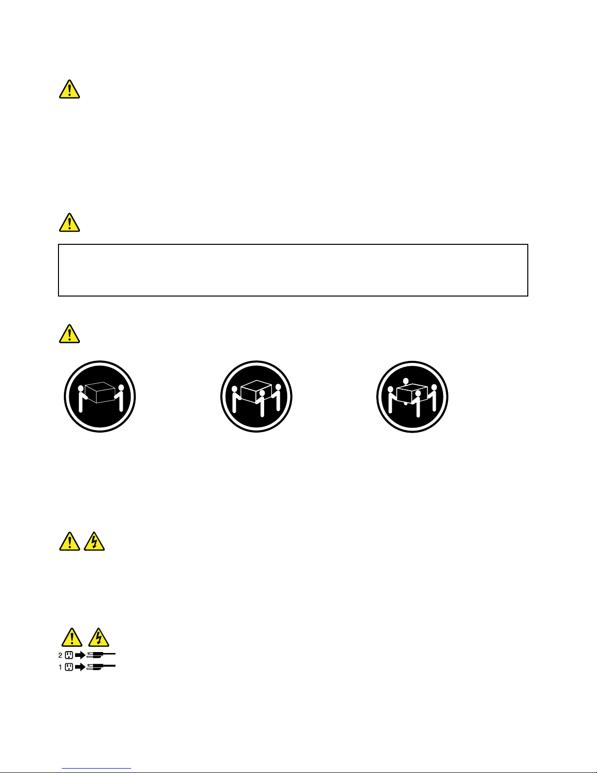
≥18kg(39.7lb)≥32kg(70.5lb)≥55kg(121.2lb)
<32kg(70.5lb)<55kg(121.2lb)<100kg(220.5lb)
CAUTION:
Usesafepracticeswhenlifting.
Statement5
CAUTION:
Thepowercontrolbuttononthedeviceandthepowerswitchonthepowersupplydonotturnoff
theelectricalcurrentsuppliedtothedevice.Thedevicealsomighthavemorethanonepower
cord.T oremoveallelectricalcurrentfromthedevice,ensurethatallpowercordsaredisconnected
fromthepowersource.
viThinkServerUserGuide
Page 9
Statement6
CAUTION:
Ifyouinstallastrain-reliefbracketoptionovertheendofthepowercordthatisconnectedtothe
device,youmustconnecttheotherendofthepowercordtoapowersourcethatiseasilyaccessible
incaseitneedstobedisconnected.
Statement7
CAUTION:
Ifthedevicehasdoors,ensurethatyouremoveorsecurethedoorsbeforemovingorliftingthe
devicetoprotectagainstpersonalinjury.Thedoorswillnotsupporttheweightofthedevice.
Statement8
CAUTION:
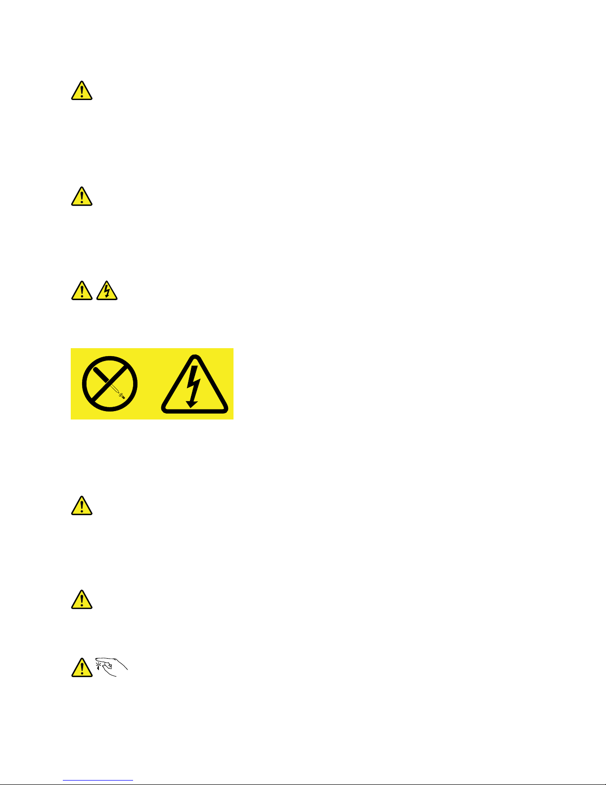
Neverremovethecoveronapowersupplyoranypartthathasthefollowinglabelattached.
Hazardousvoltage,current,andenergylevelsarepresentinsideanycomponentthathasthislabel
attached.Therearenoserviceablepartsinsidethesecomponents.Ifyoususpectaproblemwith
oneoftheseparts,contactaservicetechnician.
Statement9
CAUTION:
Disconnectthehot-swapfancablesbeforeremovingthefanfromthedevicetoprotectagainst
personalinjury.
Statement10
CAUTION:
Thefollowinglabelindicatesasharp-edgehazard.
©CopyrightLenovo2010,2012
vii
Page 10
Statement11
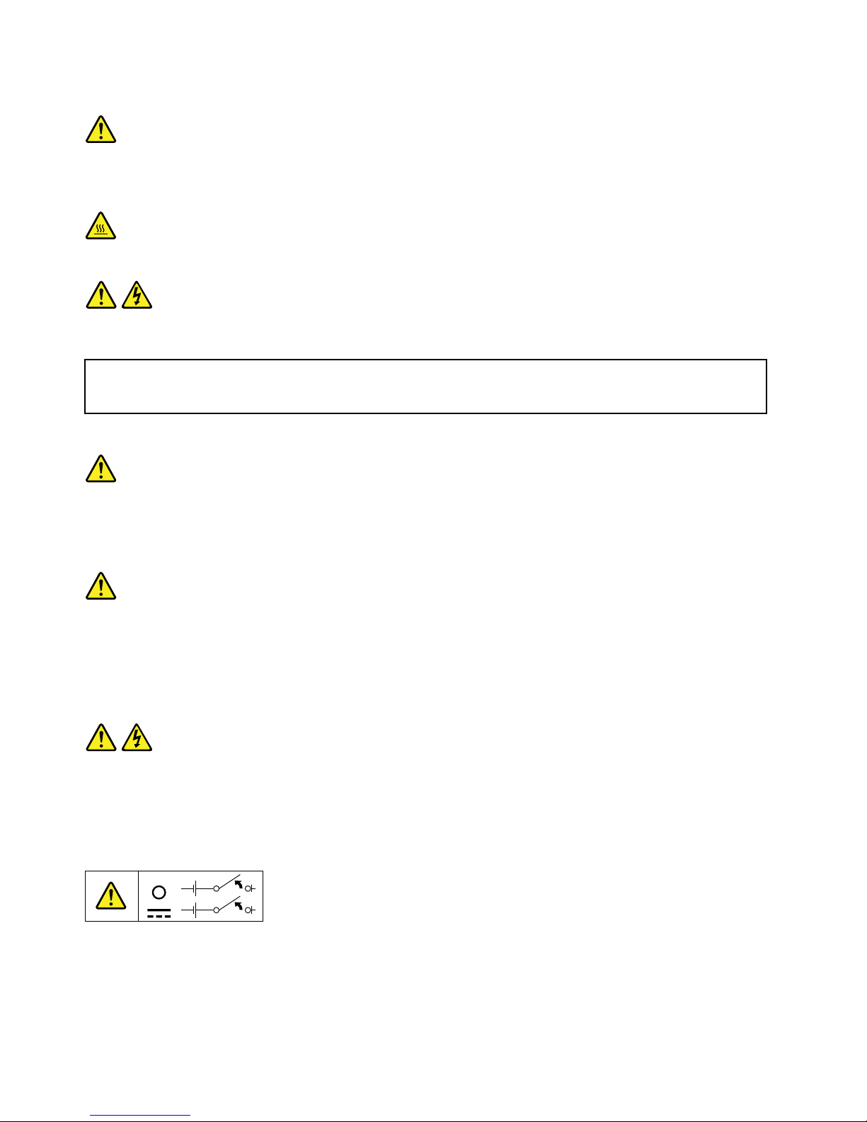
CAUTION:
Thefollowinglabelindicatesapotentialheathazard.
Statement12
DANGER
Overloadingabranchcircuitisapotentialrehazardandashockhazardundercertainconditions.To
avoidthesehazards,ensurethatyoursystemelectricalrequirementsdonotexceedbranchcurrentratings
attheinstallationsite.
Statement13
CAUTION:
Ensurethattherackissecuredproperlytoavoidtippingwhentheserverunitisextendedontherails.
Statement14
CAUTION:
SomeaccessoryoroptionboardoutputsexceedClass2orlimitedpowersourcelimits.Y ou
mustinstalltheappropriateinterconnectingcablinginaccordancewithyourlocalelectricalcode
requirements.
Statement15
CAUTION:
Thepower-controlbuttononthedevicemayputthedeviceinstandbymodeinsteadofturningoff
thedevice.Inaddition,thedevicemighthavemultipleconnectionstodcpower.T oremoveall
electricalcurrentfromthedevice,ensurethatallconnectionstodcpoweraredisconnectedat
thedcpowerinputterminals.
viiiThinkServerUserGuide
Page 11
Statement16
CAUTION:
Toreducetheriskofelectricshockorenergyhazards:
•Thisequipmentmustbeinstalledbytrainedservicepersonnelinarestricted-accesslocation,as
denedbyyourlocalelectricalcodeandthelatesteditionofIEC60950.
•Connecttheequipmenttoareliablyearthedsafetyextralowvoltage(SEL V)source.AnSELV
sourceisasecondarycircuitthatisdesignedsothatnormalandsinglefaultconditionsdonot
causethevoltagestoexceedasafelevel(60Vdirectcurrent).
•Thebranchcircuitovercurrentprotectionmustberatedinaccordancewithlocalelectricalcode
requirements.
•Use1.3mm
2
or16AmericanWireGauge(AWG)copperconductoronly,notexceeding3meters
inlength.
•T orquethewiring-terminalscrewsto1.4newton-metersor12inch-pounds.
•Provideareadilyavailable,approvedandrateddisconnectdeviceintheeldwiring.
Statement17
CAUTION:
ThisproductcontainsaClass1Mlaser.Donotviewdirectlywithopticalinstruments.
Statement18
CAUTION:
Donotplaceanyobjectontopofrack-mountedproducts.
Statement19
CAUTION:
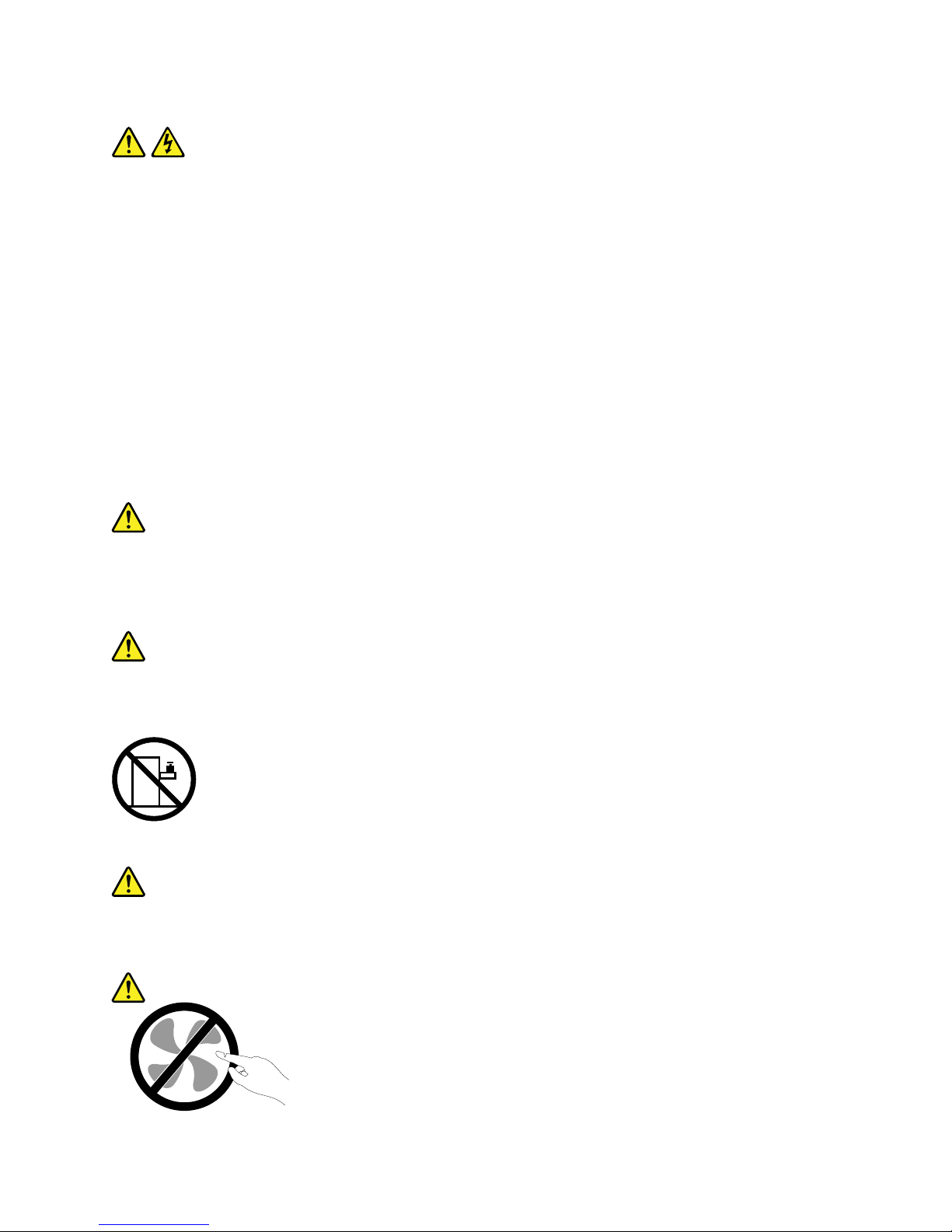
Hazardousmovingparts.Keepngersandotherbodypartsaway.
©CopyrightLenovo2010,2012
ix
Page 12

Statement20
CAUTION:
Alithiumionbatteryisprovided.T oavoidpossibleexplosion,donotburnthebattery.Replacethe
batteryonlywiththeLenovo-approvedpart.Recycleordiscardthebatteryasinstructedbylocal
regulations.
xThinkServerUserGuide
Page 13

Chapter1.Generalinformation
Thischapterprovidessomegeneralinformationaboutyourserver.
Thischaptercontainsthefollowingtopics:
•“Introduction”onpage1
•“Serverdocumentation”onpage1
Introduction
ThisUserGuideisforyourLenovo®ThinkServer®RD230server(machinetypes1043,1044,4010,and
4011).Thisdocumentcontainsthefollowinginformation:
•Settingupandcablingtheserver
•Startingandconguringtheserver
•Installingoptionsandreplacingcustomerreplaceableunits(CRUs)
•Solvingproblems
TheservercomeswiththeThinkServerEasyStartupDVDtohelpyoucongurethehardware,installdevice
drivers,andinstalltheoperatingsystem.
Theservercomeswithalimitedwarranty.Forinformationaboutthetermsofthewarrantyandgetting
serviceandassistance,seetheWarrantyandSupportInformationonthedocumentationDVDthatcomes
withyourserver.
Toobtainthemostup-to-dateinformationabouttheserverandotherLenovoproducts,goto:
http://www.lenovo.com/thinkserver
Recordinformationabouttheserverinthefollowingtable.Y ouwillneedthisinformationwhenyouregister
theserverwithLenovo.
Productname
ThinkServerRD230
Machinetype1043,1044,4010,or4011
Modelnumber
_____________________________________________
Serialnumber
_____________________________________________
Themodelnumberandserialnumberareonthelabelsonthebottomoftheserverandonthefront,visible
throughthebezel.
Serverdocumentation
Thistopicprovidesageneraldescriptionofeachdocumentforyourserverandinstructionsonhow
toobtainallthedocuments.
©CopyrightLenovo2010,2012
1
Page 14

Printeddocuments
Thefollowingdocumentsareprintedoutandincludedinyourserverpackage.
•ReadMeFirst
Thisisamultilingualdocumentyoushouldreadrst.Thisdocumentguidesyoutoreadthecomplete
warranty,support,andsafetyinformationonthedocumentationDVDthatcomeswithyourserverbefore
usingtheproduct.Thisdocumentalsoprovidesinformationabouthowtondthemostup-to-date
informationontheLenovoSupportWebsite.
•ImportantNotices
Thisdocumentincludessafetyandlegalnoticesthatyoushouldreadandunderstandbeforeusing
theserver.
•RackInstallationInstructions
Thisdocumentprovidesinstructionsonhowtoinstallyourserverintoastandardrackcabinetbyusing
therailkitshippedwiththeserver.
Note:Thisdocumentisavailableinvelanguages.AprintedEnglishversionisincludedinyourserver
package.APDFversionofFrench,German,Italian,andSpanishareprovidedonthedocumentationDVD
thatcomeswiththeserver.
DocumentationDVD
ThedocumentationDVD,whichcomeswithyourserver,containsvariousdocumentsforyourserverin
PortableDocumentFormat(PDF)andHyperT extMarkupLanguage(HTML).ThedocumentationDVDisnot
bootable.ToviewthedocumentsontheDVD,youwillneedacomputerwithaWebbrowserandtheAdobe
Readerprogram,whichisavailablefordownloadat:
http://www.adobe.com
TostartthedocumentationDVD,inserttheDVDintotheopticaldrive.TheDVDisAutoPlayenabledand
startsautomaticallyinmostenvironments.IftheDVDfailstostartorifyouareusingaLinux
®
operating
system,openthelaunch.htmlelocatedintherootdirectoryoftheDVD.
Note:LenovomaintainspagesontheWorldWideWeb,whereyoucangetthelatesttechnicalinformation
anddownloaddocumentationordevicedriversandupdates.Someinformationinthedocumentsonthe
documentationDVDmightchangewithoutnoticeaftertherstreleaseoftheDVD.Youcanalwaysobtainall
themostup-to-datedocumentationforyourserverfromtheLenovoWebsiteat:
http://www.lenovo.com/ThinkServerUserGuides
ThefollowingdocumentsareonthedocumentationDVDthatcomeswithyourserver:
•SafetyInformation
Thisisamultilingualdocumentthatincludesallthesafetystatementsforyourproductinmorethan30
languages.Besuretoreadandunderstandallthesafetystatementsbeforeusingtheproduct.
•WarrantyandSupportInformation
ThisdocumentincludestheLenovowarrantystatement,CustomerReplaceableUnits(CRUs)information,
andinformationabouthowtocontacttheLenovoCustomerSupportCenter.
•UserGuide
Thisdocumentprovidesdetailedinformationtohelpyougetfamiliarwithyourserverandhelpyouuse,
congure,andmaintainyourserver.
•RackInstallationInstructions
Thisdocumentprovidesinstructionsonhowtoinstallyourserverintoastandardrackcabinetbyusing
therailkitshippedwiththeserver.
2ThinkServerUserGuide
Page 15

•RemoteManagementUserGuide
Thisdocumentprovidesinformationaboutserverremotemanagement.ThisdocumentisinEnglishonly.
•MegaRAIDSASSoftwareUserGuide
ThisdocumentprovidesinformationaboutRedundantArrayofIndependentDisks(RAID)andhowto
usetheutilityprogramstocongure,monitor,andmaintainyourserverRAIDandrelateddevices.This
documentisinEnglishonly.
Documentonlyfortrainedservicepersonnel
ThefollowingdocumentisintendedonlyfortrainedservicepersonnelofLenovo.
HardwareMaintenanceManual
Thisdocumentprovidesdiagnosticinformation,partslisting,andreplacementproceduresforallField
ReplaceableUnits(FRUs,partsreplacedbytrainedservicepersonnel)aswellasallCRUs.Thisdocumentis
updatedfrequently,andthemostup-to-dateversionisalwaysavailableinEnglishontheLenovoWebsiteat:
http://www.lenovo.com/ThinkServerUserGuides
Chapter1.Generalinformation3
Page 16

4ThinkServerUserGuide
Page 17

Chapter2.Serversetuproadmap
Thischapterprovidesageneralroadmaptoguideyouthroughsettingupyourserver.
Theserversetupprocedurevariesdependingonthecongurationoftheserverwhenitwasdelivered.In
somecases,theserverisfullyconguredandyoujustneedtoconnecttheservertothenetworkandan
electricaloutlet,andthenyoucanturnontheserver.Inothercases,theserverneedstohavehardware
featuresinstalled,requireshardwareandrmwareconguration,andrequirestheoperatingsystemto
beinstalled.
Table1.Serversetuproadmap
TaskWheretondtheinformation
Unpack
Chapter3“Featuresandtechnologies”onpage7
Installhardware
Chapter5“Installing,removing,orreplacinghardware”onpage19
InstalltheserverintherackTheRackInstallationInstructionsmanualisprintedandalsoincludedonthe
documentationDVD.
ConnecttheEthernetcable
andpowercord
“Rearview”onpage11
Turnontheservertoverify
operation
“Turningontheserver”onpage68
ReviewtheBIOSsettings
andcustomizeasneeded
“StartingtheSetupUtilityprogram”onpage72
CongureRAID(onboard
SATARAIDortheinstalled
SASRAIDadapter)
“RAIDcontrollers”onpage80
Checkforrmwareupdates
“UsingtheEasyUpdateFirmwareUpdaterprogram”onpage84
Installoperatingsystemand
basicdrivers
“UsingtheThinkServerEasyStartupprogram”onpage80
Installanyadditionaldrivers
neededforaddedfeatures
Refertotheinstructionsthatcamewiththehardwareoption.
CongureEthernetsettings
intheoperatingsystem
Seetheoperatingsystemhelp.Thisstepisnotrequirediftheoperatingsystemwas
installedusingtheThinkServerEasyStartupprogram.
Installremotemanagement
applications
“InstallingtheThinkServerEasyManageprogram”onpage85
Installapplications
Refertothedocumentationthatcomeswiththeapplicationsthatyouwanttoinstall.
©CopyrightLenovo2010,2012
5
Page 18

6ThinkServerUserGuide
Page 19

Chapter3.Featuresandtechnologies
Whatisincludedwithyourserver
TheRD230serverpackageincludestheserver,apowercord,documentation,thedocumentationDVD,and
softwaremedia.
Features
TheRD230serveroffersthefollowingfeaturesandtechnologies:
•Microprocessor(s):TheserversupportsuptotwoIntel®Xeon®dual-core,quad-core,orhex-core
microprocessors.
•BIOS:Theserverrmwaredenesastandardinterfacebetweentheoperatingsystem,platformrmware,
andexternaldevices.
•EasyStartupDVD:TheThinkServerEasyStartupprogramguidesyouthroughthecongurationofthe
hardware,theredundantarrayofindependentdisks(RAID)controller,andtheinstallationoftheoperating
systemanddevicedrivers.
•Integratednetworksupport:
Theservercomeswithtwointegratedsingle-portGigabitEthernet
controllersandeachsupportsconnectiontoa10Mbps,100Mbps,or1000Mbpsnetwork.Formore
information,see“ConguringtheGigabitEthernetcontroller”onpage84.
•Largedata-storagecapacityandhot-swapcapability:Somehot-swapservermodelssupportfour
3.5-inchhot-swapharddiskdrives.Withthehot-swapfeature,youcanadd,remove,orreplaceharddisk
driveswithoutturningofftheserver.
•Largesystem-memorycapacity:Theserversupportsupto64GBofsystemmemory.Thememory
modulesupportserrorcorrectingcode(ECC)foruptoeightindustry-standardsingle-rankordual-rank,
1333MHz,DDR3(third-generationdouble-data-rate)registeredsynchronousdynamicrandomaccess
memory(SDRAM)dualinlinememorymodules(DIMMs).
•High-performancegraphicscontroller:Theservercomeswithanonboardhigh-performancegraphics
controllerthatsupportshighresolutionsandincludesmanyperformance-enhancingfeaturesforthe
operating-systemenvironment.
•Redundantconnection:
Thetwoonboardnetworkinterfacecontrollers(NIC)provideafailovercapability
toaredundantEthernetconnection.IfaproblemoccurswiththeprimaryEthernetconnection,all
Ethernettrafcthatisassociatedwiththeprimaryconnectionisautomaticallyswitchedtotheredundant
NIC.Iftheapplicabledevicedriversareinstalled,thisswitchingoccurswithoutdatalossandwithout
userintervention.
•IntelligentPlatformManagementInterface(IPMI)2.0:Thecommand-lineinterfaceprovidesdirect
accesstoservermanagementfunctionsthroughtheIPMI2.0protocol.Usethecommand-lineinterface
toissuecommandstocontroltheserverpower,viewsysteminformation,andidentifytheserver.Y oucan
alsosaveoneormorecommandsasatextleandruntheleasascript.
•RAIDsupport:TheserversupportstheonboardSATAsoftwareRAIDandanadd-onSASRAIDcard
(ThinkServer8708ELPSASRAIDAdapter,ThinkServer8708EM2RAIDAdapter,orThinkServerRAID
700Adapter),whicharerequiredforyoutousethehot-swapSATAorSASharddiskdrivesandto
createtheRAIDcongurations.
Specications
Thefollowinginformationisasummaryofthefeaturesandspecicationsoftheserver.Dependingonthe
servermodel,somefeaturesmightnotbeavailable,orsomespecicationsmightnotapply.
©CopyrightLenovo2010,2012
7
Page 20

Table2.Featuresandspecications
Microprocessor(s):Supportsupto
twoIntelXeondual-core,quad-core,
orhex-coremicroprocessors.Forthe
specictypeandspeedinformation
aboutthemicroprocessor,use
theSetupUtilityprogram.See
“UsingtheSetupUtilityprogram”on
page71
.Foralistofthesupported
microprocessorsforyourserver,goto
http://www.lenovo.com/thinkserver.
OntheThinkServersystemspage,
clickProducts➙Options➙
ThinkServerProcessors.
Memorymodules:
•Minimumsystemmemory:2GB
•Maximumsystemmemory:64GB
(eightmemoryslots,eachwithone
8GBRDIMMinstalled)
•Types:ECC,1333MHz,DDR3
registeredSDRAMDIMMsonly
•Slots:Eightdualinlinememory
module(DIMM)slots
•Supports2GB,4GB,and8GB
RDIMMs
Integratedgraphicscard:
•8MBvideomemory
Size:
•Height:43.6mm(1.72inches)
•Width:436mm(17.17inches)
•Depth:568mm(22.36inches)
•
Maximumweight:17kg(37.48lb)
whenfullycongured
Opticaldrive:
•SlimDVD/RW
Harddiskdriveexpansionbays
(dependingonthemodel):
Uptofour3.5-inchSATAorSAShard
diskdrives
Expansionslots:
•ThreePCIExpressslotsonthe
systemboardandthePCIExpress
x16slotisforarisercardassembly
(thereisonePCIExpressx16slot
ontherisercardassembly)
Powersupply:
Single600-watt
powersupply
Systemfans:Fivesystemfans
withautomaticenergy-savingnoise
reductiontechnology
Integratedfunctions:
•Twosingle-portGbEthernet
controllers
•SixUSB2.0connectors(twofront
andfourrear)
•TwoRJ-45Ethernetconnectors
•Oneserialport
•OneVideoGraphicsArray(VGA)
monitorconnector
Environment:
•Airtemperature:
–Serveron:10°Cto35°C(50°F
to95°F);altitude:0to914.4m
(3000ft)
–Serveron:10°Cto32°C(50°F
to89.6°F);altitude:914.4m(3
000ft)to2133.6m(7000ft)
–Serveroff:10°Cto43°C(50°F
to109.4°F);maximumaltitude:
2133.6m(7000ft)
–Shipping:-40°Cto60°C(-104°F
to140°F)
•Humidity:
–Serveron:8-90%,
non-condensing
–Serveroff:8-90%,
non-condensing
–Shippingandstorage:upto
93%,non-condensing
•Particulatecontamination:
Attention:Airborneparticulates
andreactivegasesactingalone
orincombinationwithother
environmentalfactorssuchas
humidityortemperaturemight
posearisktotheserver.
RAIDcontrollers:
•OnboardSATASoftwareRAID
•ThinkServer8708ELPSASRAID
Adapter
•ThinkServer8708EM2RAID
Adapter
•ThinkServerRAID700Adapter
Electricalinput
•Inputvoltage:
–Lowrange:
Minimum:100Vac
Maximum:127Vac
Inputfrequencyrange:50to
60Hz
–Highrange:
Minimum:200Vac
Maximum:240Vac
Inputfrequencyrange:50to
60Hz
Notes:
1.Powerconsumptionandheat
outputvarydependingonthe
numberandtypeofoptional
featuresinstalledandthe
power-managementoptional
featuresinuse.
2.Thesoundlevelsweremeasured
incontrolledacoustical
environmentsaccordingto
theproceduresspeciedbythe
AmericanNationalStandards
Institute(ANSI)S12.10and
ISO7779andarereportedin
accordancewithISO9296.
Actualsound-pressurelevelsina
givenlocationmightexceedthe
averagevaluesstatedbecause
ofroomreectionsandother
nearbynoisesources.The
noiseemissionlevelstated
isthedeclared(upperlimit)
8ThinkServerUserGuide
Page 21

Table2.Featuresandspecications(continued)
sound-powerlevel,inbels,fora
randomsampleofsystem.
3.Thereisnokeyboardconnector
ormouseconnectoronthe
server.Y oucanconnectaUSB
keyboardandUSBmouseto
theserverbyusingtheUSB
connectors.
Softwareprograms
Lenovoprovidessoftwaretohelpgetyourserverupandrunning.
EasyStartup
TheThinkServerEasyStartupprogramsimpliestheprocessofconguringRAIDandinstallingsupported
Microsoft®Windows®andLinuxoperatingsystemsanddevicedriversonyourserver.TheEasyStartup
programisprovidedwithyourserverontheThinkServerEasyStartupDVD.TheDVDisself-starting
(bootable).TheuserguidefortheEasyStartupprogramisontheDVDandcanbeaccesseddirectlyfromthe
programinterface.Foradditionalinformation,see“UsingtheThinkServerEasyStartupprogram”onpage80
.
EasyManage
TheThinkServerEasyManageAgentenablesthisservertobemanagedbythecentralizedconsoleofan
EasyManageCoreServeroverthenetwork.TheThinkServerEasyManageAgentissupportedon32-bitand
64-bitWindows,RedHat,andSUSEoperatingsystems.
Reliability,availability,andserviceability
Reliability,availability,andserviceability(hereafterreferredtoasRAS)arethreeimportantserverdesign
features.TheRASfeatureshelpyoutoensuretheintegrityofthedatastoredontheserver,theavailabilityof
theserverwhenyouneedit,andtheeasewithwhichyoucandiagnoseandcorrectproblems.
TheserverhasthefollowingRASfeatures:
•AdvancedCongurationandPowerInterface(ACPI)
•AdvancedDesktopManagementInterface(DMI)
•Automaticmemorydownsizingonerrordetection
•Automaticrestartonnon-maskableinterrupt(NMI)
•Availabilityofmicrocodelevel
•Built-in,menu-drivensetup,systemconguration,andRAIDconguration
•Built-inmonitoringforfan,temperature,andvoltage
•Coolingfanswithspeed-sensingcapability
•ECCDDR3SDRAMwithSerialPresenceDetect(SPD)
•Errorcodesandmessagestohelpyouidentifyproblems
•Generatingerrorlogsforthepower-onself-test(POST)failures
•Hot-swapSASharddiskdrives
•IntegratedEthernetcontrollers
•IntelligentPlatformManagementInterface(IPMI)2.0
Chapter3.Featuresandtechnologies9
Page 22

•Power-onself-test(POST)
•RedundantEthernetconnectionwithfailovercapability(requiresanoptionalEthernetcard)
•Standbyvoltageforsystem-managementfeaturesandmonitoring
•System-errorlight-emittingdiode(LED)onthefrontpanel
•Vitalproductdata(VPD),includingtheserialnumberinformationandreplacementpartnumbers,storedin
thenonvolatilememoryforeasierremotemaintenance
10ThinkServerUserGuide
Page 23
Chapter4.Locatingparts,controls,LEDs,andconnectors
Thischapterprovidesinformationtohelpyoulocateyourserverparts,controls,light-emittingdiodes
(LEDs),andconnectors.
Frontview
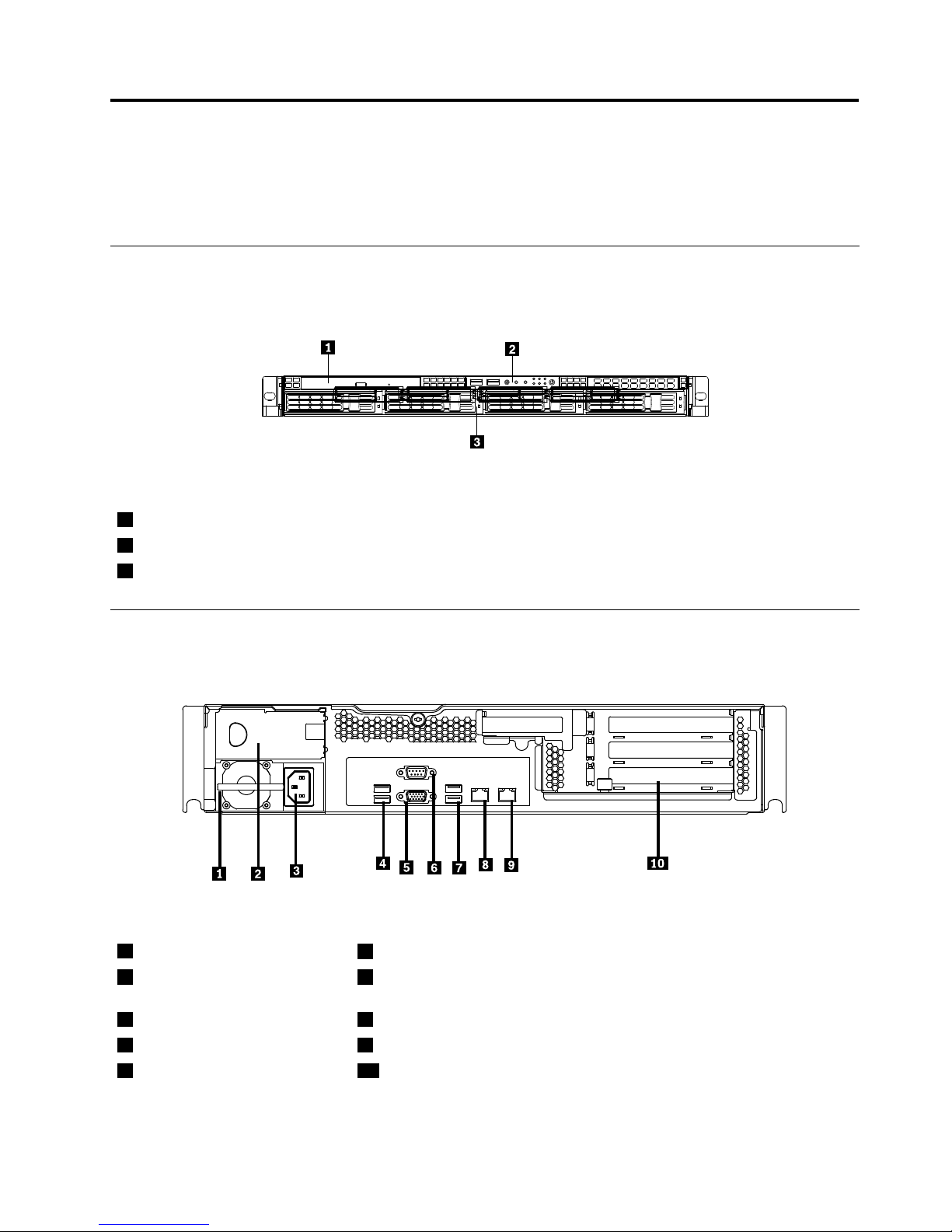
Thefollowingillustrationshowsthedrivesandpartsonthefrontoftheserver.
Figure1.Frontviewoftheserver
1Slimopticaldrive
2Frontcontrolpanel(see“Frontcontrolpanel”onpage12)
3Mountingpointfor3.5-inchharddiskdrive
Rearview
Thefollowingillustrationshowsthelocationsoftheconnectorsandpartsontherearoftheserver.
Figure2.Rearviewoftheserver
1Powersupply1
6Serialport
2Powersupply2bay(blankand
coveredbyabaybezel)
7USBconnectors(3and4)
3Powercordconnector8Ethernetconnector1
4USBconnectors(1and2)9Ethernetconnector2(sharewithMGMT)
5VGAmonitorconnector10PCIexpansionslot
©CopyrightLenovo2010,2012
11
Page 24
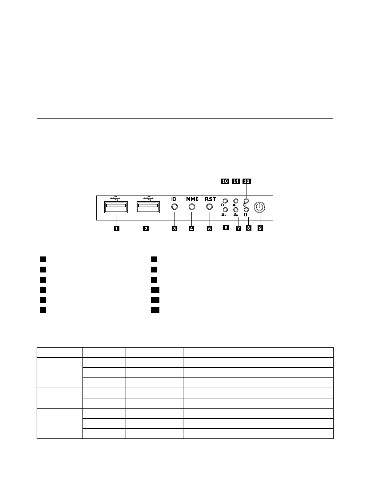
ConnectorDescription
PowercordconnectorUsedtoconnectthepowercord.
Ethernetconnector
UsedtoattachanEthernetcableforalocalareanetwork(LAN).
Serialport
Usedtoattachadevicethatusesa9-pinserialport.
USBconnectorUsedtoattachadevicethatusesaUSBconnector,suchasaUSBkeyboard
oraUSBmouse.
VGAmonitorconnectorUsedtoattachaVGAmonitororotherdevicesthatuseaVGAmonitorconnector.
Frontcontrolpanel
Thissectionprovidesinformationaboutthefrontcontrolpaneloftheserver.
Thefollowingillustrationhelpsyouidentifytheconnectors,controls,andLEDsonthefrontcontrolpanelof
yourserver.
Figure3.Frontcontrolpanellocations
1USBconnector
7Ethernet2statusLED
2USBconnector
8HarddiskdrivestatusLED
3IDbutton9PowerbuttonandLED
4NMIbutton
10SystemIDLED
5Resetbutton
11SystemstatusLED
6Ethernet1statusLED
12LED(willnotbeusedinthisserver)
ThefollowingtabledescribesthemeaningoftheLEDsonthefrontcontrolpanel.
Table3.FrontcontrolpanelLEDs
LEDStateColorDescription
OnGreen
Theserverpowerison.
Blinking
GreenTheserverpowerisunderS1.
PowerLED
OffOff
Theserverpowerisoff.
OffOff
Theharddiskdriveisnotactive. Harddiskdrive
LED
Blinking
Green
Theharddiskdriveisactive.
OnGreen
LANislinked.
Blinking
Green
LANisactive.
Ethernet1
statusLED
OffOff
LANisnotlinked.
12ThinkServerUserGuide
Page 25
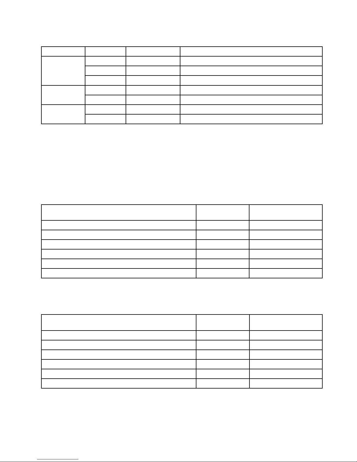
Table3.FrontcontrolpanelLEDs(continued)
LEDStateColorDescription
OnGreen
LANislinked.
Blinking
Green
LANisactive.
Ethernet2
statusLED
OffOff
LANisnotlinked.
On
Red
Failure.Overtemperatureorovervoltage. Systemstatus
LED
OffOff
Nofailure.
On
Blue
Systemisidentied.
IDLED
OffOffSystemisnotidentied.
EachharddiskdrivehastwostatusLEDsonthefront.ThegreenLED1(bottom)indicatesactivityand
theamberLED2(top)indicatestheRAIDstatus.
Notes:IftheonboardSATAandonboardSATAsoftwareRAIDarecongured,notethefollowing:
•TheSGPIOconnectorofthe4–portSATAcableinthechassisshouldbeconnectedtotheJ45connector
onthesystemboard.See“Locatingpartsonthesystemboard”onpage15
.
•ThefunctionoftheamberLED2isonlyavailableafteryouentertheoperatingsystem.
Table4.HarddiskdriveLEDs
Description
GreenLED1
(bottom)AmberLED2(top)
Harddiskdriveisnotpresent.
OffOff
Harddiskdriveispresentbutisnotactive.
OnOff
Harddiskdriveispresentandactive.Blinking
Off
Serverisintheprocessoflocatingtheharddiskdrive.On
Blinking
RAIDhasfailed.
OffOn
Harddiskdriveisrebuilding.BlinkingBlinking
Note:Forsomemodels,theharddiskdrivestatusinformationmightbedifferentfromtheinformationlistedin
theabovetable.Fortheseservermodels,refertothefollowingtwotablesfortheharddiskdriveLEDstatus.
Table5.HarddiskdriveLEDsfortheonboardSA TAandonboardSATAsoftwareRAIDcongurations(somemodels)
Description
GreenLED1
(bottom)AmberLED2(top)
Harddiskdriveisnotpresent.
OffOff
Harddiskdriveispresentbutisnotactive.
OnOff
Harddiskdriveispresentandactive.Blinking
Off
Serverisintheprocessoflocatingtheharddiskdrive.OnOff
RAIDhasfailed.
OnOff
Harddiskdriveisrebuilding.Blinking
Off
Chapter4.Locatingparts,controls,LEDs,andconnectors13
Page 26
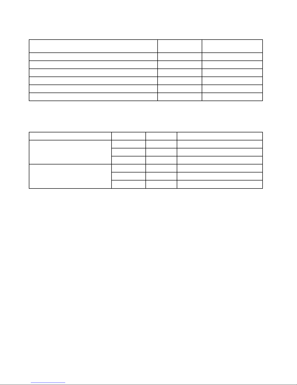
Table6.HarddiskdriveLEDsfortheadd-onSASRAIDadapterconguration(somemodels)
Description
GreenLED1
(bottom)AmberLED2(top)
Harddiskdriveisnotpresent.
OffOff
Harddiskdriveispresentbutisnotactive.
OnOff
Harddiskdriveispresentandactive.Blinking
Off
Serverisintheprocessoflocatingtheharddiskdrive.
BlinkingBlinking
RAIDhasfailed.
OffOn
Harddiskdriveisrebuilding.BlinkingBlinking
TheEthernet1andEthernet2connectorshavetwostatusLEDsthatindicatetheLANconnectionand
activityoftheconnection.
Table7.EthernetLEDs
LEDStateColorDescription
OnGreen10/100/1000Mblinked
Blinking
Green10/100/1000Mbactivity
RJ-45linkage/activity(left)
OffOff
NoLANconnection.
On
Amber1000Mblinkedandactive
OnGreen
100Mblinkedandactive
RJ-45speed(right)
OffOff
10MbmodeornoLANconnection.
14ThinkServerUserGuide
Page 27
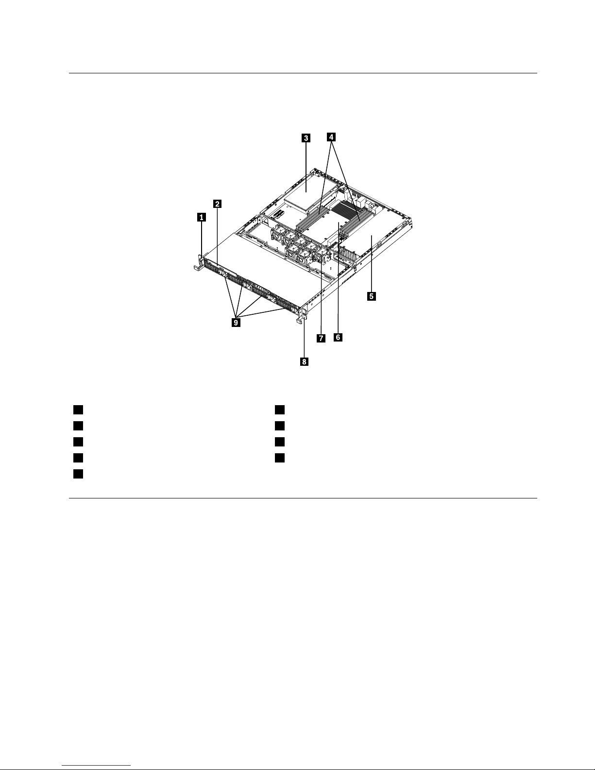
Locatingservercomponents
Thefollowingillustrationshowsthelocationsofthemajorcomponentsinyourserver.
Figure4.Servercomponentlocations
1Lefthandleofthechassis
6Heatsinkassemblyandmicroprocessor(s)underneath
2Slimopticaldrive7Systemfans
3PCIcard
8Righthandleofthechassis
4Memorymodules
9Mountingpointsforthe3.5-inchharddiskdrives
5Powersupplyassembly
Locatingpartsonthesystemboard
Thefollowingillustrationsshowthelocationsofthepartsonthesystemboard.
Chapter4.Locatingparts,controls,LEDs,andconnectors15
Page 28

Figure5.Locatingmajorpartsonthesystemboard
1Memoryslot(CPU1DIMMCHA1)13SATAconnector1
2Memoryslot(CPU1DIMMCHA0)14SATAconnector2
3Memoryslot(CPU1DIMMCHB0)15SATAconnector3
4Memoryslot(CPU1DIMMCHC0)16SATAconnector5
5Powerconnector2(forCPU0)17SATAconnector4
624-pinpowerconnectorforthesystemboard
18Systemboardbattery
7Microprocessor(CPU0)19PCIExpressx8slot(fortherisercardassembly)
8Memoryslot(CPU0DIMMCHA1)20PCIExpressx8slot(fortherisercardassembly)
9Memoryslot(CPU0DIMMCHA0)21PCIExpressx16slot(fortherisercardassembly)
10Memoryslot(CPU0DIMMCHB0)22Microprocessor(CPU1)
11Memoryslot(CPU0DIMMCHC0)23Powerconnector3(forCPU1)
12SATAconnector0
16ThinkServerUserGuide
Page 29
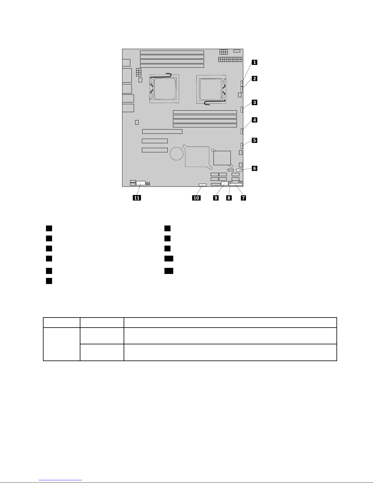
Figure6.Locatingotherconnectorsonthesystemboard
1J47(systemfan1connector)7J35(forfrontcontrolcable)
2J48(systemfan2connector)8JP1(ClearCMOSjumper)
3J50(systemfan3connector)9USB2connector
4J56(systemfan4connector)10J45connector(fortheSGPIOconnectorofthe4–portSATAcable)
5J49(systemfan5connector)11JP8(COM2connector)
6J19(frontUSBconnector)
Thefollowingtableintroducesthejumperswitchesonthesystemboard.
Table8.Jumpersettings
JumperPositionDescription
Pins1-2
Thedefaultpositionatwhichthejumperisplacedonpins1-2duringthenormal
operationofthesystem.
JP1:Clear
CMOS
Pins2-3
Ifthejumperisplacedonpins2-3,whenthejumperismovedbacktothedefault
position,thesettingsofCMOSwillbeclearedautomaticallyatthenextstartup.
Note:BeforeclearingtheCMOS,turnofftheserveranddisconnectthepowercord.Movethejumperfrom
pins1-2topins2-3.Waitmorethanveminutesandthenmovethejumperbacktothenormalposition
(pins1-2)toclearCMOS.
Chapter4.Locatingparts,controls,LEDs,andconnectors17
Page 30
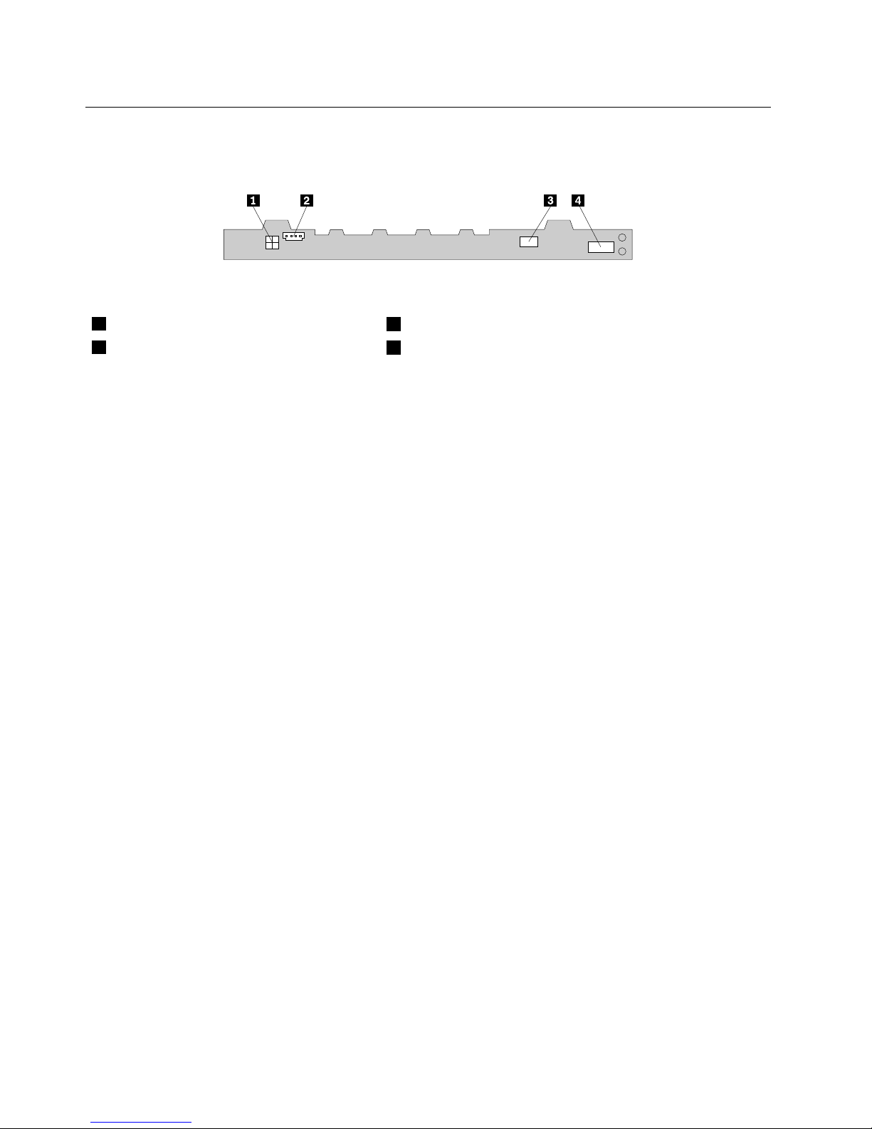
Locatingconnectorsonthebackplane
Thefollowingillustrationshowstheconnectorlocationsonthebackplane.
Figure7.Backplaneconnectorlocations
1Powerconnector2
3Opticaldrivepowerconnector
2Powerconnector1
4Mini-SASsignalcableconnector
18ThinkServerUserGuide
Page 31

Chapter5.Installing,removing,orreplacinghardware
Thischapterprovidesinstructionsonhowtoinstall,remove,orreplacehardwareforyourserver.
Thischaptercontainsthefollowingtopics:
•“Guidelines”onpage19
•“Removingtheservercover”onpage21
•“Installing,removing,orreplacingoptionalhardwaredevices”onpage22
•“Installing,removing,orreplacinghardwaredevices”onpage41
•“Completingthepartsreplacement”onpage67
Guidelines
Thissectionprovidessomeguidelinesthatyoushouldreadandunderstandbeforeusingyourserver.
Basicguidelines
Beforeyouusetheserver,besuretoreadandunderstandthefollowingguidelines:
•BesuretoreadandunderstandtheSafetyInformationandtheWarrantyandSupportInformationonthe
documentationDVDthatcomeswithyourproduct,and“Guidelines”onpage19
.Theseinformationwill
helpyouworksafely.T oobtainacopyofthepublications,goto:
http://www.lenovo.com/support
•Whenyouinstallyournewserver,taketheopportunitytodownloadandapplythemostrecentrmware
updates.Thisstepwillhelpyoutoensurethatanyknownissuesareaddressedandtheserverisreadyto
functionatoptimalperformance.Todownloadrmwareupdatesforyourserver,dothefollowing:
1.Gotohttp://www.lenovo.com/support.
2.ClickDownload&Drivers➙ThinkServerandthenfollowtheinstructionsontheWebpageto
downloadrmwareupdatesforyourserver.
•Observegoodhousekeepingintheareawhereyouareworking.Putremovedcoversandotherparts
inasafeplace.
•Ifyoumustturnontheserverwhiletheservercoverisremoved,makesurethatnooneisneartheserver
andthatnotoolsorotherobjectshavebeenleftinsidetheserver.
•Donotattempttoliftanobjectthatyouthinkistooheavyforyou.Ifyouhavetoliftaheavyobject,
observethefollowingprecautions:
–Makesurethatyoucanstandsafelywithoutslipping.
–Distributetheweightoftheobjectequallybetweenyourfeet.
–Useaslowliftingforce.Nevermovesuddenlyortwistwhenyouliftaheavyobject.
–Toavoidstrainingthemusclesinyourback,liftbystandingorbypushingupwithyourlegmuscles.
•Makesurethatyouhaveanadequatenumberofproperlygroundedelectricaloutletsfortheserver,
monitor,andotherdevices.
•Backupallimportantdatabeforeyoumakechangestodrives.
•Haveasmallat-bladescrewdriveravailable.
•ToviewtheerrorLEDsonthesystemboardandinternalcomponents,leavetheserverconnectedto
power.
©CopyrightLenovo2010,2012
19
Page 32

•Youdonothavetoturnofftheservertoinstallorreplacehot-swapfans,redundanthot-swapacpower
supplies,orhot-plugUSBdevices.However,youmustturnofftheserverbeforeperforminganystepsthat
involveinstalling,removing,orreplacingadaptercablesornon-hot-swapoptionaldevicesorcomponents.
•Aftercompletinganyinstallation,removal,orreplacementprocedure,reinstallallsafetyshields,guards,
labels,andgroundwires.
•Foralistofsupportedoptionaldevicesfortheserver,gotohttp://www.lenovo.com/thinkserver.
•Whenworkinginsidetheserver,youmightndsometaskseasierifyoulaytheserveronitsside.
Systemreliabilityguidelines
Tohelpensurepropercoolingandsystemreliability,makesurethatyoufollowtheseguidelines:
•EverydrivebayhasaninternaldriveinstalledoranElectroMagneticCompatibility(EMC)shieldinstalled.
•Iftheserverhasredundantpower,everypowersupplybayhasapowersupplyassemblyinstalled.
•Leaveadequatespacearoundtheservertomakesurethattheservercoolingsystemworkswell.
•Properlyroutethecables.Forsomeoptions,suchasPCIcards,followthecablinginstructionsthat
comewiththeoptions.
•Makesurethatyoureplaceafailingfanwithin48hours.
•Whenreplacingahot-swapdrive,installthenewhot-swapdrivewithintwominutesofremoval.
•Donotremoveanyairductorairbafeswhiletheserverisrunning.Operatingtheserverwithoutthe
airductorairbafesmightcausethemicroprocessortooverheat.
•Thesecondmicroprocessorsocketalwayscontainseitheramicroprocessorsocketcoverora
microprocessor.
Handlingstatic-sensitivedevices
Attention:
Donotopenthestatic-protectivepackagecontainingthenewpartuntilthedefectiveparthasbeenremovedfromthe
serverandyouarereadytoinstallthenewpart.Staticelectricity,althoughharmlesstoyou,canseriouslydamage
servercomponentsandparts.
Whenyouhandleserverpartsandcomponents,taketheseprecautionstoavoidstatic-electricitydamage:
•Limityourmovement.Movementcancausestaticelectricitytobuilduparoundyou.
•Wearanelectrostatic-dischargewriststrap,ifoneisavailable.
•Alwayscarefullyhandlethepartsandothercomponents(suchasPCIcards,memorymodules,system
boards,andmicroprocessors)byitsedgesoritsframe.Donottouchsolderjoints,pins,orexposed
circuitry.
•Preventothersfromtouchingthepartsandothercomputercomponents.
•Beforeyoureplaceanewpart,touchthestatic-protectivepackagecontainingthenewparttoametal
expansion-slotcoverorotherunpaintedmetalsurfaceontheserverforatleasttwoseconds.This
reducesstaticelectricityfromthepackageandyourbody.
•Removethenewpartfromthestatic-protectivepackageanddirectlyinstallitintheserverwithout
placingitonanyothersurface.Ifitishardforyoutodothisinyourspecicsituation,placethe
static-protectivepackageofthenewpartonasmooth,levelsurface,andthenplacethenewparton
thestatic-protectivepackage.
•Donotplacethepartontheservercoverorothermetalsurface.
•Takeadditionalcarewhenhandlingdevicesduringcoldweather.Heatingreducesindoorhumidity
andincreasesstaticelectricity.
20ThinkServerUserGuide
Page 33

Workinginsidetheserverwiththepoweron
Attention:
Staticelectricitythatisreleasedtointernalservercomponentswhentheserveristurnedonmightcausetheserverto
halt,whichmightresultinthelossofdata.Toavoidthispotentialproblem,alwaysuseanelectrostatic-dischargewrist
straporothergroundingsystemwhenyouworkinsidetheserverwiththepoweron.
Theserversupportshot-swapdevicesandisdesignedtooperatesafelywhileitisturnedonandthecoveris
removed.Followtheseguidelineswhenyouworkinsidetheserverwiththepoweron:
•Avoidwearingloose-ttingclothingonyourforearms.Buttonlong-sleevedshirtsbeforeworkinginside
theserver;donotwearcufflinkswhileyouareworkinginsidetheserver.
•Donotallowyournecktieorscarftohanginsidetheserver.
•Removejewelry,suchasbracelets,necklaces,rings,andloose-ttingwristwatches.
•Removeitemsfromyourshirtpocket,suchaspensandpencils.Theseitemsmightfallintotheserveras
youleanoverit.
•Avoiddroppinganymetallicobjectsintotheserver,suchaspaperclips,hairpins,andscrews.
Removingtheservercover
Attention:Donotopenyourserverorattemptanyrepairbeforereadingandunderstandingthe“Safetyinformation”
onpageiiiand“Guidelines”onpage19.
Thissectionprovidesinstructionsonhowtoremovetheservercover.
Attention:Forpropercoolingandairow,installtheservercoverbeforeturningontheserver.Operatingthe
serverformorethan30minuteswiththeservercoverremovedmightdamageservercomponents.
Toremovetheservercover,dothefollowing:
1.Removeallmediafromthedrives.Then,turnoffallattacheddevicesandtheserver.
2.Disconnectallpowercordsfromelectricaloutlets.
3.Disconnectthepowercord(s),Input/Output(I/O)cables,andallothercablesthatareconnectedto
theserver.
Chapter5.Installing,removing,orreplacinghardware21
Page 34
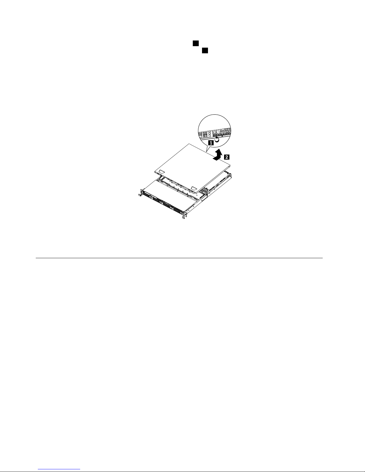
4.Loosenthethumbscrewintherearoftheservercover1.Then,slidetheservercovertotherearuntil
youcanliftituptocompletelyremoveitfromthechassis2.
Notes:
a.Thethumbscrewissecurelyinstalledandyouneedtouseatool,forexampleascrewdriver,to
loosenit.
b.Thethumbscrewisanintegratedpartoftheservercoveranditcannotberemovedfromtheserver
cover.
Figure8.Removingtheservercover
Toreinstalltheservercover,see“Installingtheservercover”onpage67.
Installing,removing,orreplacingoptionalhardwaredevices
Thissectionprovidesinstructionsonhowtoinstall,remove,orreplaceoptionalhardwaredevicesforyour
server.Youcanexpandthecapabilitiesofyourserverbyaddingmemorymodules,PCIcards,ordrives,
andmaintainyourserverbyreplacingthefailingoptionalhardwaredevices.Ifyouarereplacinganoptional
hardwaredevice,performtheremovalprocedureandthenperformtheinstallationprocedurefortheoptional
hardwaredevicethatyouwanttoreplace.
Installingorremovingamemorymodule
Thissectionprovidesinstructionsonhowtoinstallorremoveamemorymodule.Foralistofthesupported
memorymodulesforyourserver,gotohttp://www.lenovo.com/thinkserver.OntheThinkServersystems
page,clickProducts➙Options➙ThinkServerMemory.
Memorymoduleinstallationrules
YourserverhaseightmemoryslotsforinstallingorreplacingDDR3SDRAMDIMMsthatprovideuptoa
maximumof64GBofsystemmemory.
Thefollowingtablesprovideinformationaboutthememorymoduleinstallationrulesthatyoushould
considerwheninstallingamemorymodule.The“X”markindicatesthesuggestedmemoryslot(s)into
whichthememorymodule(s)shouldbeinstalledindifferentsituations.Thenumber,forexample1,2,or3,
indicatestheinstallationsequence.See“Locatingpartsonthesystemboard”onpage15
toidentifythe
variousmemoryslots.
22ThinkServerUserGuide
Page 35
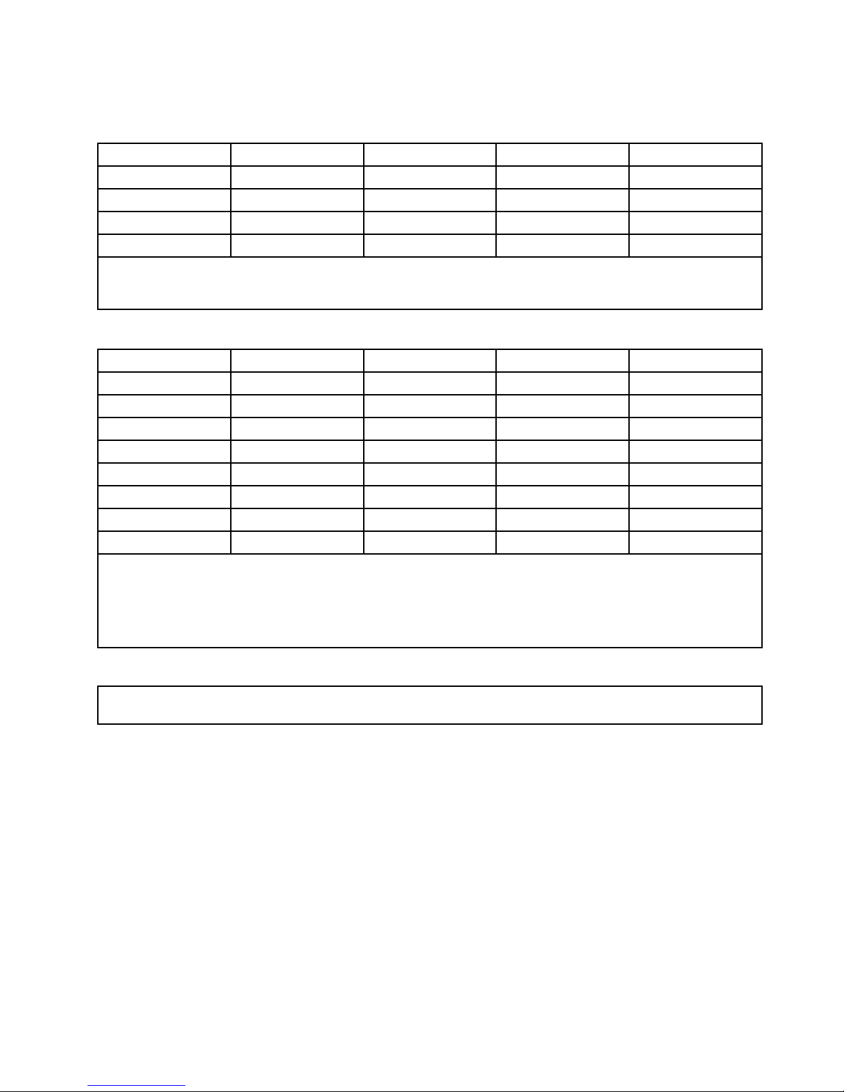
Note:Allmemorymoduletypesandcapacitiesmustbeconsistent.
Table9.DIMMinstallationruleswhenasinglemicroprocessor(CPU0)isinstalled
DIMMslotOneDIMMTwoDIMMsThreeDIMMsFourDIMMs
CPU0DIMMCHA1
X,4
CPU0DIMMCHA0
XX,1X,1X,1
CPU0DIMMCHB0
X,2X,2X,2
CPU0DIMMCHC0
X,3X,3
Note:InstallingDIMMsonchannelAandchannelBofCPU0shouldenableChannelMirroringMode.Thismode
requiresthatyouinstalltheDIMMsinpair,andtheDIMMinstallationforChannelMirroringModeisoneDIMMon
CPU0DIMMCHA0andoneDIMMonCPU0DIMMCHB0whenasinglemicroprocessor(CPU0)isinstalled.
Table10.DIMMinstallationruleswhentwomicroprocessors(CPU0andCPU1)areinstalled
DIMMslotTwoDIMMsFourDIMMsSixDIMMsEightDIMMs
CPU0DIMMCHA1
X,7
CPU0DIMMCHA0
X,1X,1X,1X,1
CPU0DIMMCHB0
X,3X,3X,3
CPU0DIMMCHC0
X,5X,5
CPU1DIMMCHA1
X,8
CPU1DIMMCHA0
X,2X,2X,2X,2
CPU1DIMMCHB0
X,4X,4X,4
CPU1DIMMCHC0
X,6X,6
Note:FortheChannelMirroringMode,itrequiresthatyouinstalltheDIMMsinpair,andtheDIMMinstallationfor
ChannelMirroringModewhentwomicroprocessors(CPU0andCPU1)areinstalledisshownbelow.Followthis
sequenceratherthanthesequencelistedaboveifyouwanttousetheChannelMirroringMode.
1.Pair1:installaDIMMonCPU0DIMMCHA0andtheninstallaDIMMonCPU0DIMMCHB0.
2.Pair2:installaDIMMonCPU1DIMMCHA0andtheninstallaDIMMonCPU1DIMMCHB0.
Installingamemorymodule
Attention:Donotopenyourserverorattemptanyrepairbeforereadingandunderstandingthe“Safetyinformation”
onpageiii
and“Guidelines”onpage19.
Thissectionprovidesinstructionsonhowtoinstallamemorymodule.
Toinstallamemorymodule,dothefollowing:
1.Removeallmediafromthedrivesandturnoffallattacheddevicesandtheserver.Then,disconnectall
powercordsfromelectricaloutletsanddisconnectallcablesthatareconnectedtotheserver.
2.Removetheservercover.See“Removingtheservercover”onpage21.
3.Locatetheappropriatememoryslotonthesystemboardintowhichyouwillinstallthememorymodule.
Tooptimizesystemperformance,followtherelatedmemorymoduleinstallationrulesandinstallthe
memorymoduleintoamemoryslotstartingwiththememorymodulefarthestfromthemicroprocessor.
See“Memorymoduleinstallationrules”onpage22
.
Chapter5.Installing,removing,orreplacinghardware23
Page 36
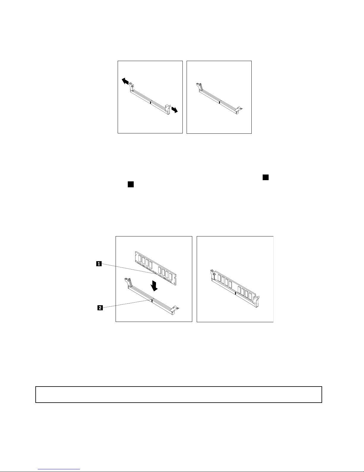
4.Opentheretainingclipsofthememoryslotintowhichyouwanttoinstallthememorymodule.
Figure9.Openingtheretainingclipsofthememoryslot
5.Touchthestatic-protectivepackagethatcontainsthenewmemorymoduletoanyunpaintedmetal
surfaceontheoutsideoftheserver.Then,removethenewmemorymodulefromthepackage.
6.Positionthenewmemorymoduleoverthememoryslot.Makesurethatthenotch1onthenewmemory
moduleisalignedwiththekey2inthememoryslot.Then,pressthenewmemorymodulestraightdown
intothememoryslotuntiltheretainingclipscloseandthenewmemorymodulesnapsintoposition.
Note:Ifthereisagapbetweenthememorymoduleandtheretainingclips,thememorymodulehas
notbeencorrectlyinstalled.Opentheretainingclips,removethememorymodule,andthenreinstallit
intotheslot.
Figure10.Installingthememorymodule
Whattodonext:
•Toworkwithanotherpieceofhardware,gototheappropriatesection.
•Tocompletetheinstallation,goto“Completingthepartsreplacement”onpage67
.
Removingamemorymodule
Attention:Donotopenyourserverorattemptanyrepairbeforereadingandunderstandingthe“Safetyinformation”
onpageiii
and“Guidelines”onpage19.
Thissectionprovidesinstructionsonhowtoremoveamemorymodule.
Toremoveamemorymodule,dothefollowing:
24ThinkServerUserGuide
Page 37
1.Removeallmediafromthedrivesandturnoffallattacheddevicesandtheserver.Then,disconnectall
powercordsfromelectricaloutletsanddisconnectallcablesthatareconnectedtotheserver.
2.Removetheservercover.See“Removingtheservercover”onpage21.
3.Locatethememoryslotwiththememorymodulethatyouwanttoremove.See“Locatingpartsonthe
systemboard”onpage15forthelocationsofthememoryslots.
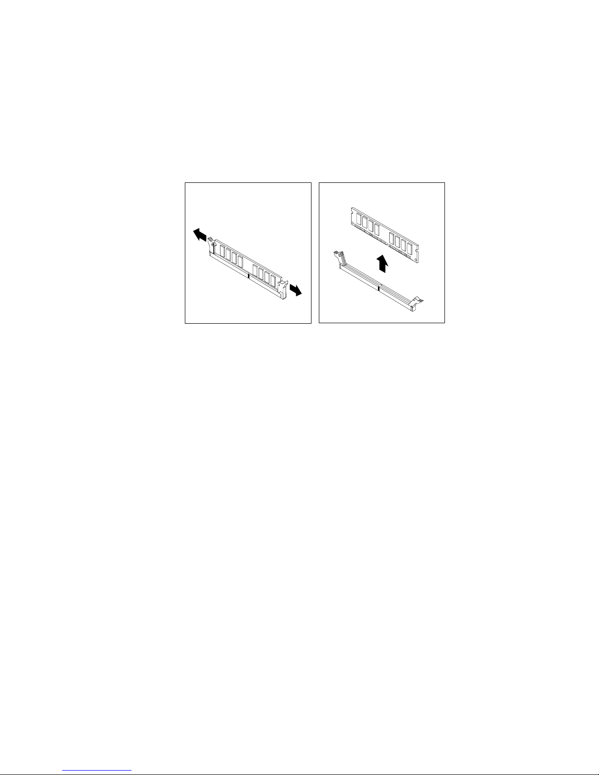
4.Carefullyopentheretainingclipsoneachendofthememoryslotandthengraspthememorymodule
straightupbyitsedges.
Figure11.Removingthememorymodule
5.Ifyouareinstructedtoreturnthefailingmemorymodule,followallpackaginginstructionsanduseany
packagingmaterialsthataresuppliedtoyouforshipping.
Whattodonext:
•Toworkwithanotherpieceofhardware,gototheappropriatesection.
•Tocompletetheremovalprocedure,goto“Completingthepartsreplacement”onpage67
.
Removingorinstallinginternaldrives
Thissectionprovidesinstructionsonhowtoremoveorinstallinternaldrivesfortheserver.
See“Specications”onpage7forinformationaboutthetypesofinternaldrivesthattheserversupportsand
otherimportantinformation,andsee“Frontview”onpage11forthelocationsofthedrivebaysintheserver.
Wheninstallinganinternaldrive,besuretoconsiderthefollowinginformation:
•Makesurethatyouhaveallthecablesandotherequipmentthatisspeciedinthedocumentationthat
comeswiththedrive.
•Selectthedrivebayinwhichyouwanttoinstallthedrive.
•Checktheinstructionsthatcomewiththedrivetoseewhetheryouhavetosetanyswitchesorjumpers
onthedrive.IfyouareinstallingaSASdevice,besuretosettheSASIDforthatdevice.
•TheEMIintegrityandcoolingoftheserverareprotectedbyhavingallbays,PCIslots,andPCIExpress
slotscoveredoroccupied.Whenyouinstalladrive,PCIcard,orPCIExpresscard,savetheEMC
shieldandllerpanelfromthebay,PCIcardslot,orPCIExpresscardslotintheeventthatyoulater
removethedevice.
•Foralistofthesupportedharddiskdrivesforyourserver,gotohttp://www.lenovo.com/thinkserver.On
theThinkServersystemspage,clickProducts➙Options➙ThinkServerHardDrives.
Chapter5.Installing,removing,orreplacinghardware25
Page 38
Removingtheopticaldrive
Attention:Donotopenyourserverorattemptanyrepairbeforereadingandunderstandingthe“Safetyinformation”
onpageiiiand“Guidelines”onpage19.
Thissectionprovidesinstructionsonhowtoremovetheopticaldrive.
Toremovetheopticaldrive,dothefollowing:
1.Removeallmediafromthedrivesandturnoffallattacheddevicesandtheserver.Then,disconnectall
powercordsfromelectricaloutletsanddisconnectallcablesthatareconnectedtotheserver.
2.Removetheservercover.See“Removingtheservercover”onpage21.
3.Disconnectthepowercablefromtheopticaldrivepowerconnectoronthebackplane.See“Locating
connectorsonthebackplane”onpage18.
4.DisconnectthesignalcablefromtheSATA5connectoronthesystemboard.See“Locatingpartson
thesystemboard”onpage15.
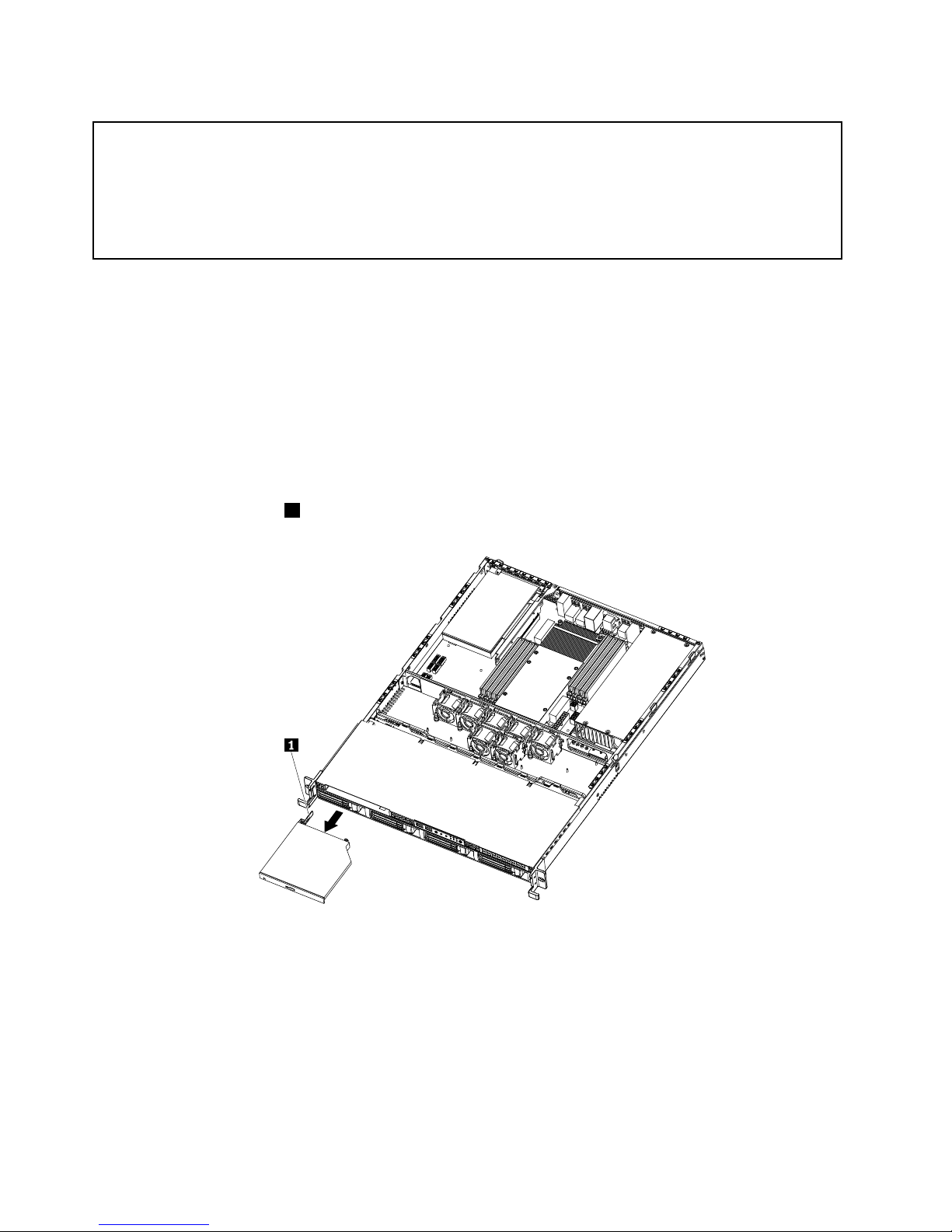
5.Presstheretentiontab1andslidetheopticaldriveoutofthefrontoftheserver.
Figure12.Removingtheopticaldrive
6.Disconnectthepowercableandthesignalcablefromtherearoftheremovedopticaldrive.
26ThinkServerUserGuide
Page 39
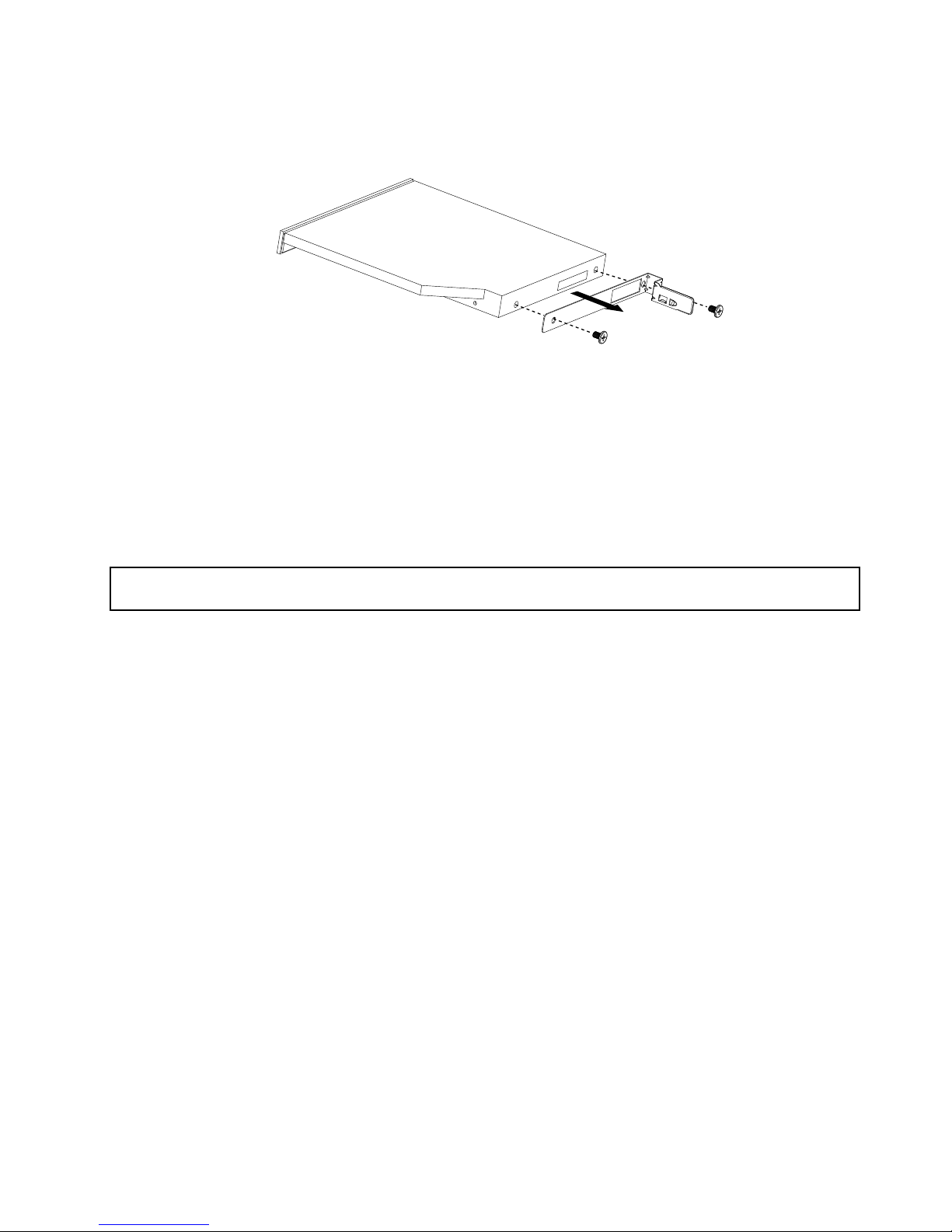
7.Removetheopticaldriveretentiontabbyremovingthetwoscrewsthatsecurethetab.Savethe
retentiontabtousewhenyouinstallanewopticaldrive.
Figure13.Removingtheopticaldriveretentiontab
8.Ifyouareinstructedtoreturntheremovedopticaldrive,followallpackaginginstructionsanduseany
packagingmaterialsthataresuppliedtoyouforshipping.
Whattodonext:
•Toworkwithanotherpieceofhardware,gototheappropriatesection.
•Tocompletetheremovalprocedure,goto“Completingthepartsreplacement”onpage67.
Installingtheopticaldrive
Attention:Donotopenyourserverorattemptanyrepairbeforereadingandunderstandingthe“Safetyinformation”
onpageiiiand“Guidelines”onpage19.
Thissectionprovidesinstructionsonhowtoinstalltheopticaldrive.
Toinstalltheopticaldrive,dothefollowing:
1.Ifyouarereplacingtheopticaldrive,makesurethat:
•Youhaveallthecablesandotherequipmentthatisspeciedinthedocumentationthatcomes
withthenewopticaldrive.
•Youhavecheckedtheinstructionsthatcomewiththenewopticaldrivetodeterminewhetheryou
mustsetanyswitchesorjumpersinthedrive.
•Youhaveremovedtheretentiontabfromtherearoftheoldopticaldriveandhaveitavailablefor
installationonthenewopticaldrive.
Note:Ifyouareinstallingadrivethatcontainsalaser,observethefollowingsafetyprecautions.
Chapter5.Installing,removing,orreplacinghardware27
Page 40
Statement3
CAUTION:
Whenlaserproducts(suchasCD-ROMs,DVDdrives,beropticdevices,ortransmitters)are
installed,notethefollowing:
•Donotremovethecovers.Removingthecoversofthelaserproductcouldresultinexposure
tohazardouslaserradiation.Therearenoserviceablepartsinsidethedevice.
•Useofcontrolsoradjustmentsorperformanceofproceduresotherthanthosespeciedherein
mightresultinhazardousradiationexposure.
DANGER
SomelaserproductscontainanembeddedClass3AorClass3Blaserdiode.Notethefollowing.
Laserradiationwhenopen.Donotstareintothebeam,donotviewdirectlywithoptical
instruments,andavoiddirectexposuretothebeam.
2.Touchthestatic-protectivepackagethatcontainsthenewopticaldrivetoanyunpaintedmetalsurface
ontheserver.Then,removetheopticaldrivefromthepackageandplaceitonastatic-protective
surface.
3.Followtheinstructionsthatcomewiththeopticaldrivetosetjumpersorswitches,ifthereareany.
28ThinkServerUserGuide
Page 41
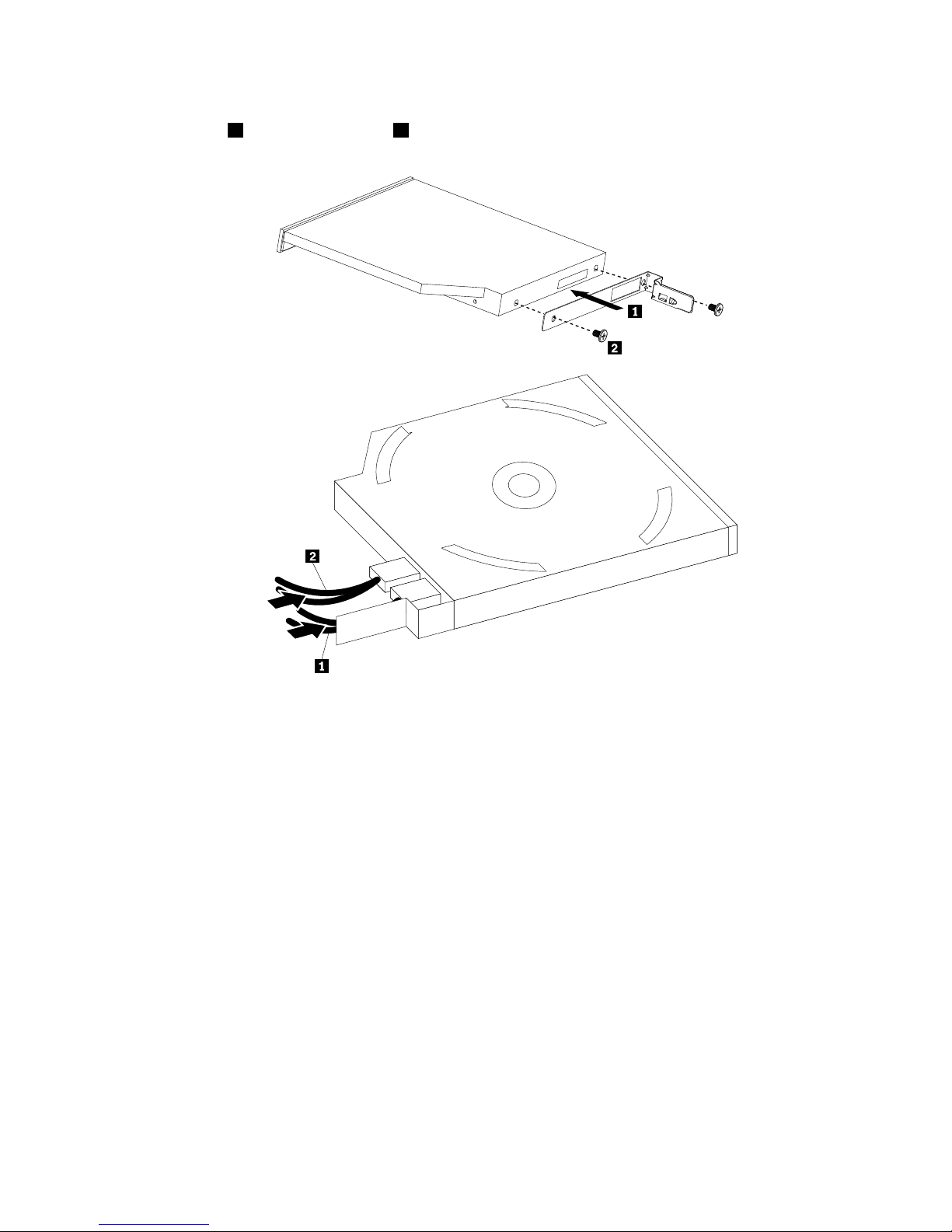
4.Installthetwoscrewstosecuretheretentiontabtotherearofthenewopticaldrive.Then,connectthe
signalcable1andthepowercable2totherearofthenewopticaldrive.
Figure14.Installingtheretentiontabandconnectingthecables
Chapter5.Installing,removing,orreplacinghardware29
Page 42
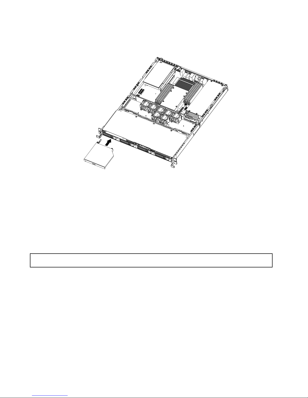
5.Routethecablesthroughthedrivebayholeinthefrontandthenslidetheopticaldriveintothedrive
bayuntilitsnapsintoposition.
Figure15.Installingtheopticaldrive
6.Connectthepowercabletotheopticaldrivepowerconnectoronthebackplane.See“Locating
connectorsonthebackplane”onpage18.
7.ConnectthesignalcabletotheSATA5connectoronthesystemboard.See“Locatingpartsonthe
systemboard”onpage15.
Whattodonext:
•Toworkwithanotherpieceofhardware,gototheappropriatesection.
•Tocompletetheinstallation,goto“Completingthepartsreplacement”onpage67
.
Removingahot-swapharddiskdrive
Attention:Donotopenyourserverorattemptanyrepairbeforereadingandunderstandingthe“Safetyinformation”
onpageiiiand“Guidelines”onpage19.
Thissectionprovidesinstructionsonhowtoremoveahot-swapharddiskdrive.Thissectionappliesonlyto
servermodelsthathavehot-swapharddiskdrivesinstalled.
Attention:Tomaintainpropersystemcooling,donotoperatetheserverformorethan10minuteswithout
eitheradriveorallerpanelinstalledineachdrivebay.
Toremoveahot-swapharddiskdrive,dothefollowing:
Note:Youdonothavetoturnofftheserverwhenremovingahot-swapharddiskdrive.
30ThinkServerUserGuide
Page 43
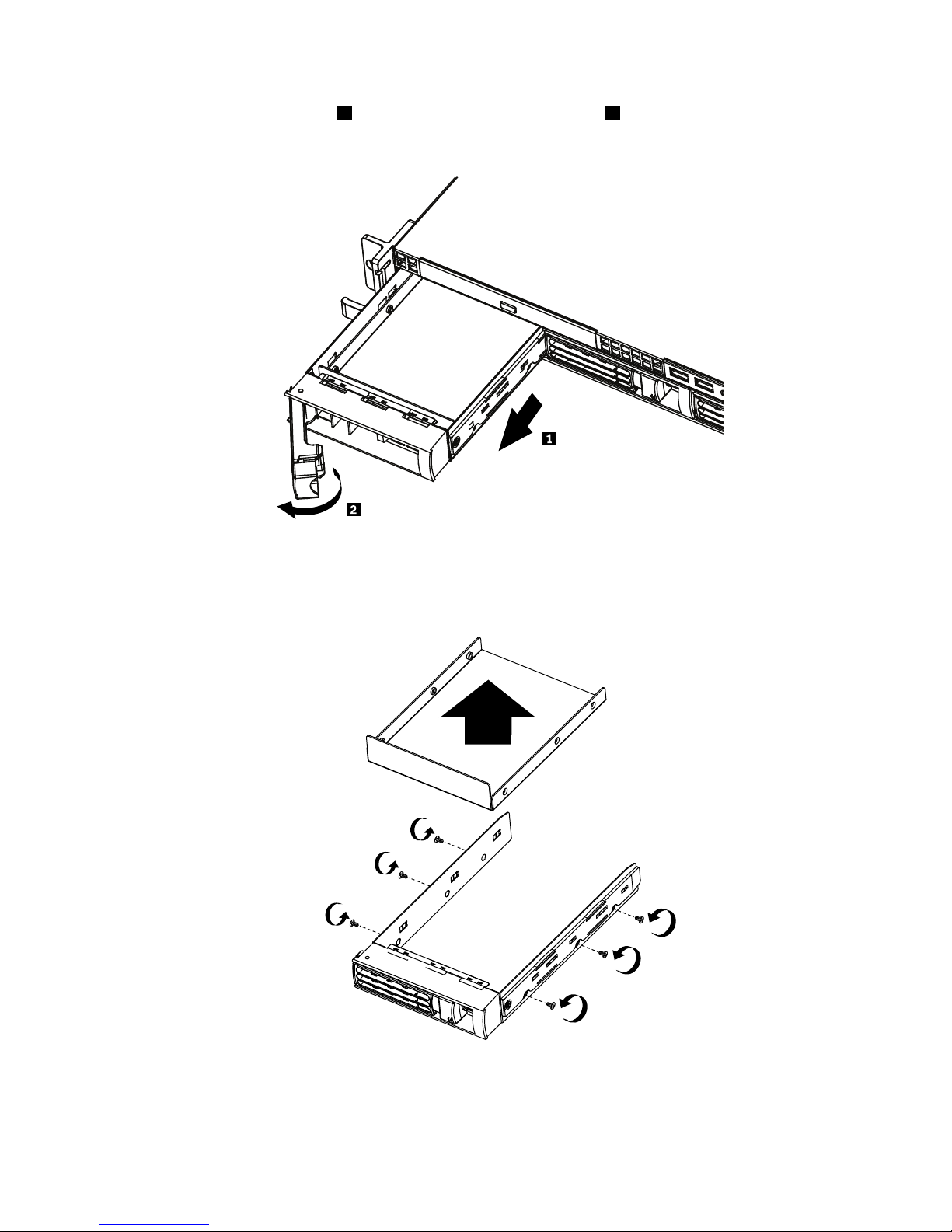
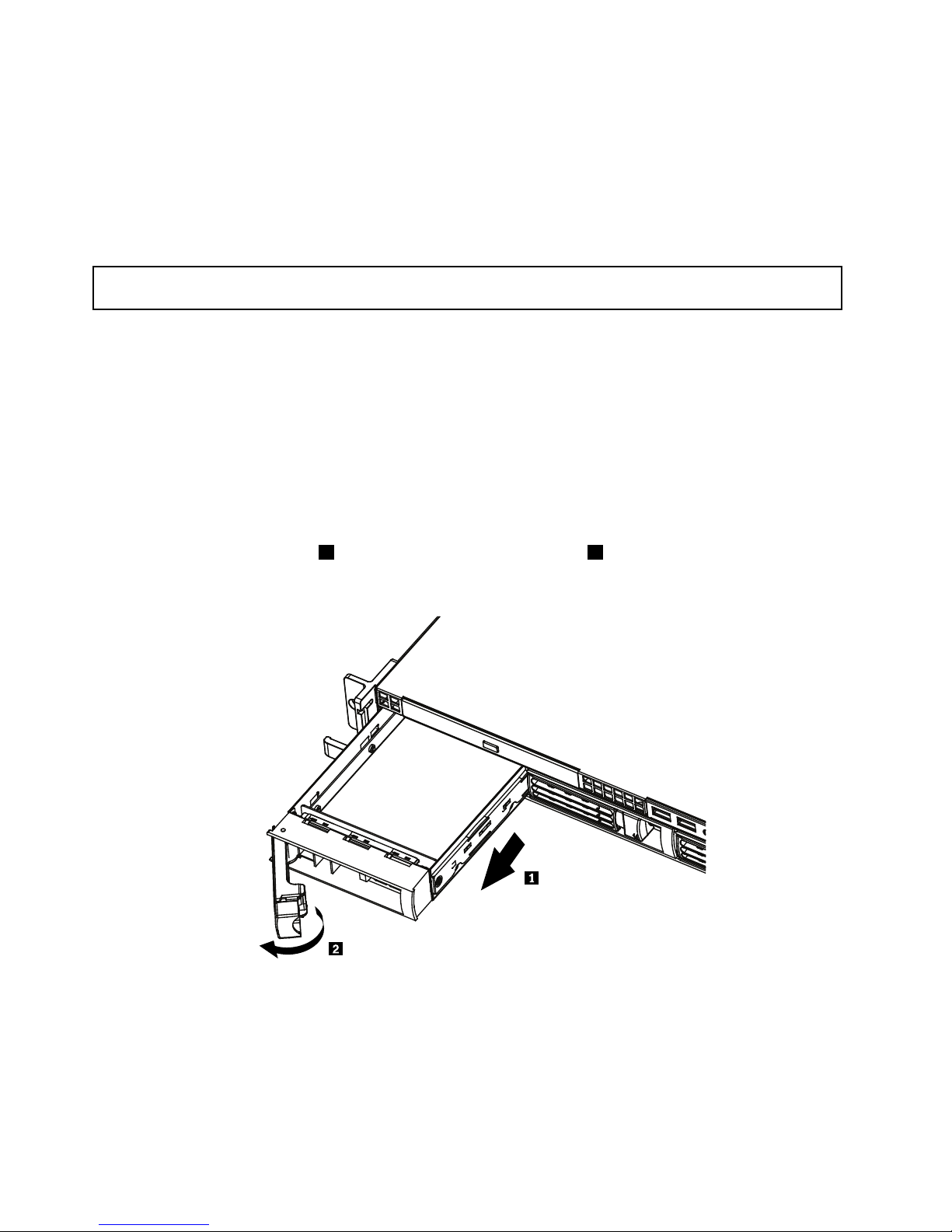
1.Rotatethedrivetrayhandle2oftheharddiskdrivetrayassembly1totheopenposition.Then,grasp
thehandleandpullthedrivetrayassemblywiththeharddiskdriveoutofthebay.
Figure16.Removingtheharddiskdrivetrayassemblywiththeharddiskdrive
2.Removethescrewsthatsecuretheharddiskdriveinthetray.Then,removetheharddiskdrive.
Figure17.Removinga3.5-inchharddiskdrive
Chapter5.Installing,removing,orreplacinghardware31
Page 44
3.Ifyouareinstructedtoreturntheremovedharddiskdrive,followallpackaginginstructionsanduseany
packagingmaterialsthataresuppliedtoyouforshipping.
Whattodonext:
•Toworkwithanotherpieceofhardware,gototheappropriatesection.
•Tocompletetheremovalprocedure,goto“Completingthepartsreplacement”onpage67.
Installingahot-swapharddiskdrive
Attention:Donotopenyourserverorattemptanyrepairbeforereadingandunderstandingthe“Safetyinformation”
onpageiiiand“Guidelines”onpage19.
Thissectionprovidesinstructionsonhowtoinstallahot-swapharddiskdrive.Thissectionappliesonlyto
servermodelsthatsupporthot-swapharddiskdrives.
Attention:Tomaintainpropersystemcooling,donotoperatetheserverformorethan10minuteswithout
eitheradriveorallerpanelinstalledineachdrivebay.
Notes:
1.Youdonothavetoturnofftheserverfortheinstallationofahot-swapharddiskdrive.
2.ThecablescomewiththeSATAharddiskdriveoptionkitwillnotbeusedinthisserver.
Toinstallahot-swapharddiskdrive,dothefollowing:
1.Rotatethedrivetrayhandle2oftheharddiskdrivetrayassembly1totheopenposition.Then,grasp
thehandleandpullthedrivetrayassemblyoutofthebay.
Figure18.Removingtheharddiskdrivetrayassembly
32ThinkServerUserGuide
Page 45
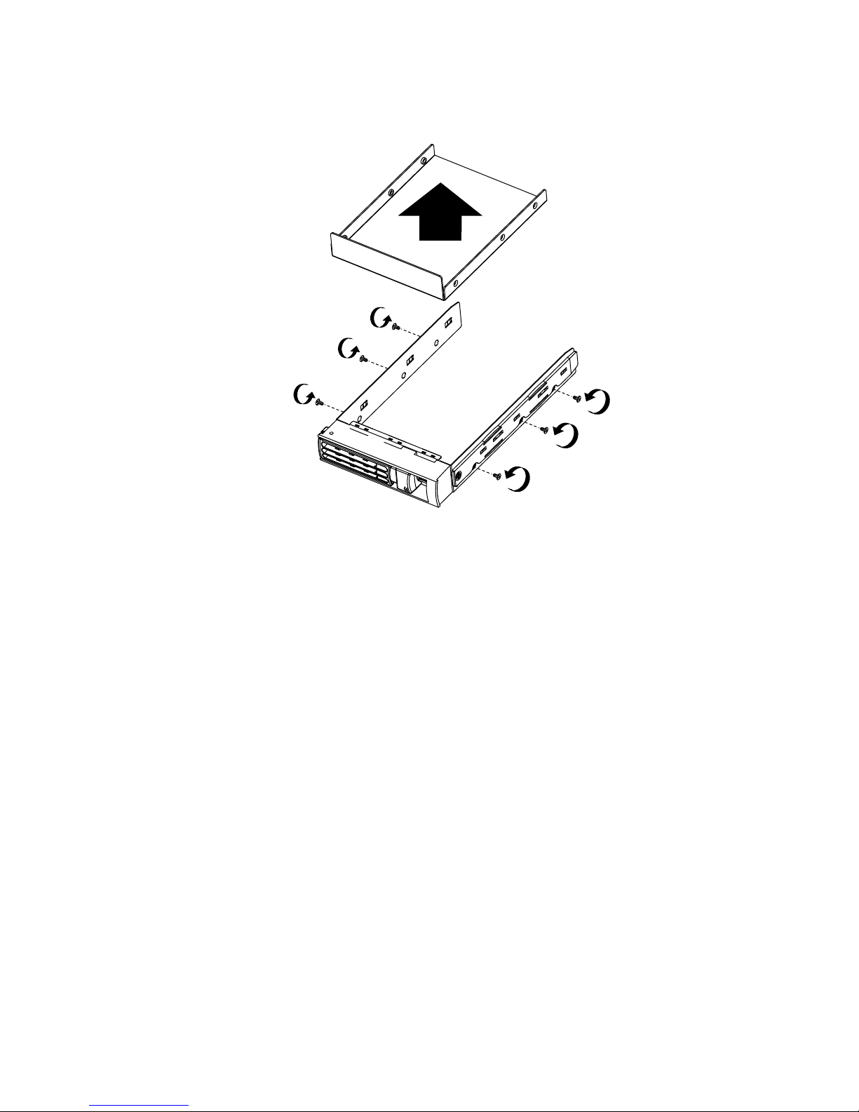
2.Removethescrewsthatsecuretheplasticllerandthenremovetheplasticller.
Figure19.Removingtheller
3.Touchthestatic-protectivepackagethatcontainsthenewharddiskdrivetoanyunpaintedmetal
surfaceontheserver.Then,removetheharddiskdrivefromthepackageandplaceitona
static-protectivesurface.
4.Makesurethatthedrivetrayhandleisintheopenposition.
Chapter5.Installing,removing,orreplacinghardware33
Page 46
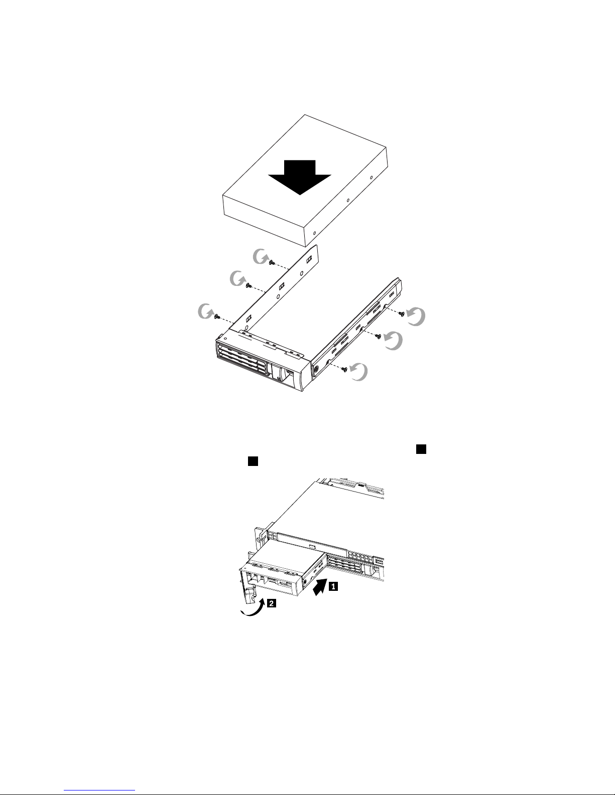
5.Alignthescrewholesinbothsidesoftheharddiskdrivewiththecorrespondingholesinthetray.Then,
installthescrewstosecuretheharddiskdriveinthetray.
Figure20.Installinga3.5-inchharddiskdrive
6.Keepthehandleontheharddiskdrivetrayassemblyfullyopen,slidethetraywiththeharddiskdrive
intothecorrespondingmountingpointofthehot-swapharddiskdrivebay1,andthenslightlypress
thehandletolockthetrayintoplace2.
7.ChecktheharddiskdrivestatusLEDstomakesurethattheharddiskdriveisoperatingcorrectly.Y ou
mighthavetorestarttheserverforthedrivetoberecognized.IftheamberharddiskdrivestatusLED
foradriveislitcontinuously,itindicatesthatthedriveisfaultyandmustbereplaced;ifthegreenhard
diskdriveactivityLEDisashing,thisindicatesthatthedriveisbeingaccessed.
Note:IftheserverisconguredforRAIDoperationusingaRAIDcontroller,youmighthaveto
recongurethediskarraysafteryoureplaceharddiskdrives.
34ThinkServerUserGuide
Page 47
Whattodonext:
•Toworkwithanotherpieceofhardware,gototheappropriatesection.
•Tocompletetheinstallation,goto“Completingthepartsreplacement”onpage67.
Installingorremovingtherisercardassembly
Thissectionprovidesinstructionsonhowtoinstallorremovetherisercardassembly.
Installingtherisercardassembly
Attention:Donotopenyourserverorattemptanyrepairbeforereadingandunderstandingthe“Safetyinformation”
onpageiiiand“Guidelines”onpage19.
Thissectionprovidesinstructionsonhowtoinstalltherisercardassembly.Therisercardassemblyhasa
PCIcardinstalledonit.
Toinstalltherisercardassembly,dothefollowing:
Note:Useanydocumentationthatcomeswiththerisercardassemblyandfollowthoseinstructionsin
additiontotheinstructionsinthissection.
1.Removeallmediafromthedrivesandturnoffallattacheddevicesandtheserver.Then,disconnectall
powercordsfromelectricaloutletsanddisconnectallcablesthatareconnectedtotheserver.
2.Removetheservercover.See“Removingtheservercover”onpage21.
3.LocatetheappropriatePCIslotonthesystemboardforinstallingtherisercardassembly.See“Locating
partsonthesystemboard”onpage15.
4.Touchthestatic-protectivepackagethatcontainstherisercardassemblytoanyunpaintedmetal
surfaceontheserver.Then,removetherisercardassemblyfromthestatic-protectivepackage.
Chapter5.Installing,removing,orreplacinghardware35
Page 48
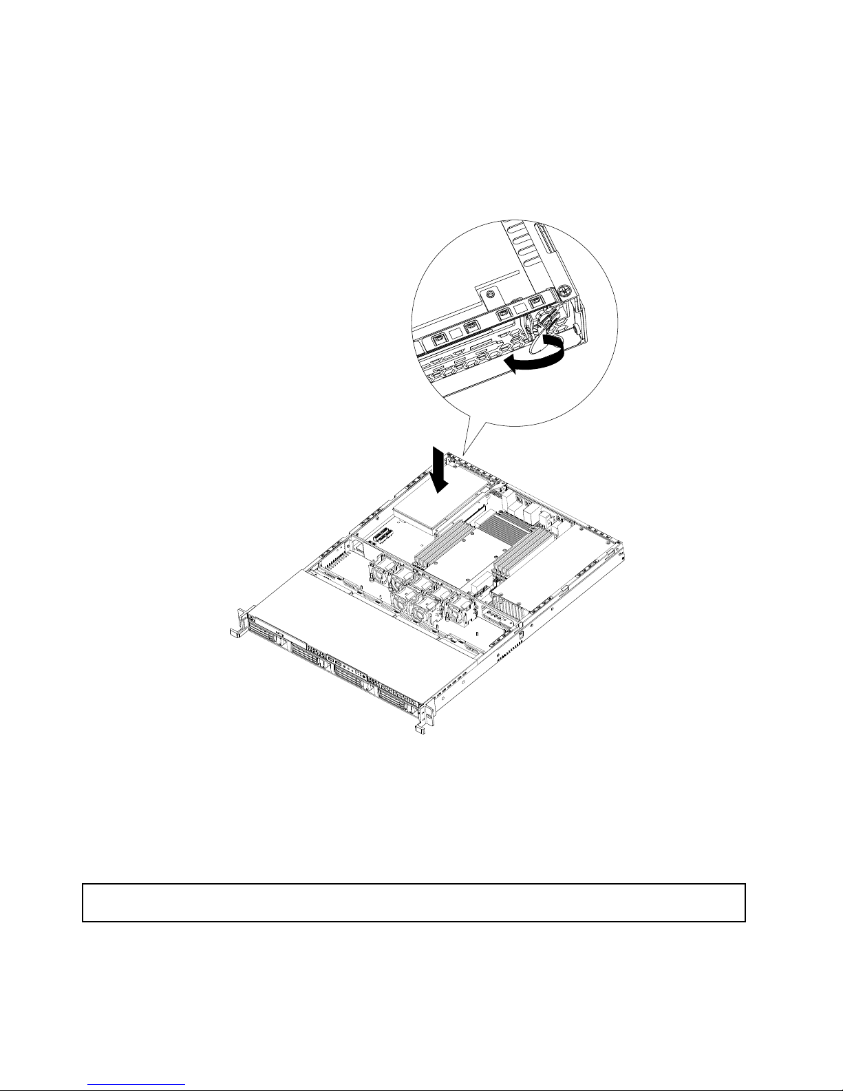
5.Presstherisercardassembly(mighthavingaPCIcardinstalled)downintotheappropriatePCIcardslot
onthesystemboard.Then,closetheretentiontabtosecurethePCIcard(installedontherisercard
assembly)andtheninstallthefasteningscrewtosecuretherisercardassemblyinplace.
Note:TherisercardassemblymighthaveaPCIcardalreadyinstalledonit.CarefullytthePCIcard
intotheserver.
Figure21.Installingtherisercardassembly
Whattodonext:
•Toworkwithanotherpieceofhardware,gototheappropriatesection.
•Tocompletetheinstallation,goto“Completingthepartsreplacement”onpage67
.
Removingtherisercardassembly
Attention:Donotopenyourserverorattemptanyrepairbeforereadingandunderstandingthe“Safetyinformation”
onpageiii
and“Guidelines”onpage19.
ThissectionprovidesinstructionsonhowtoremovetherisercardassemblywithaPCIcardinstalled.
Toremovetherisercardassembly,dothefollowing:
36ThinkServerUserGuide
Page 49
Note:Useanydocumentationthatcomeswiththerisercardassemblyandfollowthoseinstructionsin
additiontotheinstructionsinthissection.
1.Removeallmediafromthedrivesandturnoffallattacheddevicesandtheserver.Then,disconnectall
powercordsfromelectricaloutletsanddisconnectallcablesthatareconnectedtotheserver.
2.Removetheservercover.See“Removingtheservercover”onpage21.
3.DisconnectanycablesfromthePCIcardoranycablesthatimpedeaccesstotherisercardassembly.
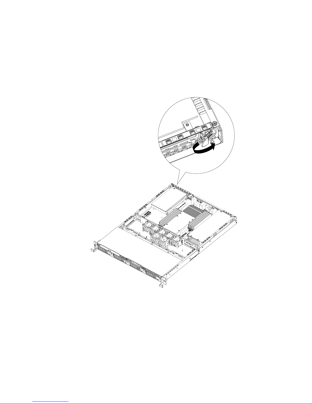
4.OpentheretentiontabthatsecuresthePCIcard,whichisinstalledontherisercardassembly.
Figure22.Openingtheretentiontab
Chapter5.Installing,removing,orreplacinghardware37
Page 50
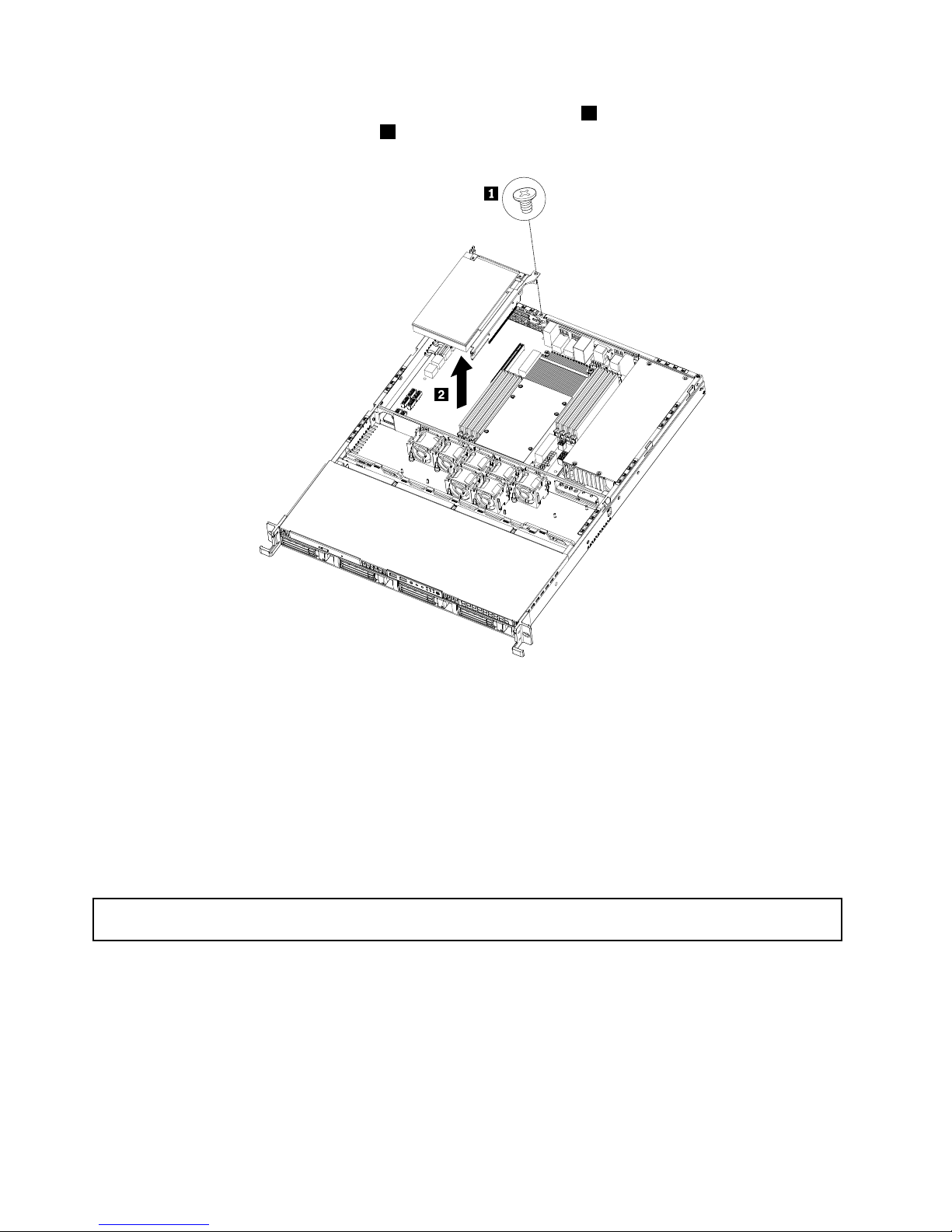
5.Removethefasteningscrewthatsecurestherisercardassembly1andlifttherisercardassembly
straightupbyitsedgestoremoveit2.
Figure23.Removingtherisercardassembly(withaPCIcardinstalled)
Whattodonext:
•Toworkwithanotherpieceofhardware,gototheappropriatesection.
•Tocompletetheremovalprocedure,goto“Completingthepartsreplacement”onpage67.
InstallingorremovingaPCIcard
ThissectionprovidesinstructionsonhowtoinstallorremoveaPCIcard.
InstallingaPCIcard
Attention:Donotopenyourserverorattemptanyrepairbeforereadingandunderstandingthe“Safetyinformation”
onpageiii
and“Guidelines”onpage19.
ThissectionprovidesinstructionsonhowtoinstallaPCIcard.
ToinstallaPCIcard,dothefollowing:
Note:UseanydocumentationthatcomeswiththePCIcardandfollowthoseinstructionsinadditionto
theinstructionsinthissection.
1.Removeallmediafromthedrivesandturnoffallattacheddevicesandtheserver.Then,disconnectall
powercordsfromelectricaloutletsanddisconnectallcablesthatareconnectedtotheserver.
38ThinkServerUserGuide
Page 51
2.Removetheservercover.See“Removingtheservercover”onpage21.
3.Removetherisercardassembly.See“Removingtherisercardassembly”onpage36.
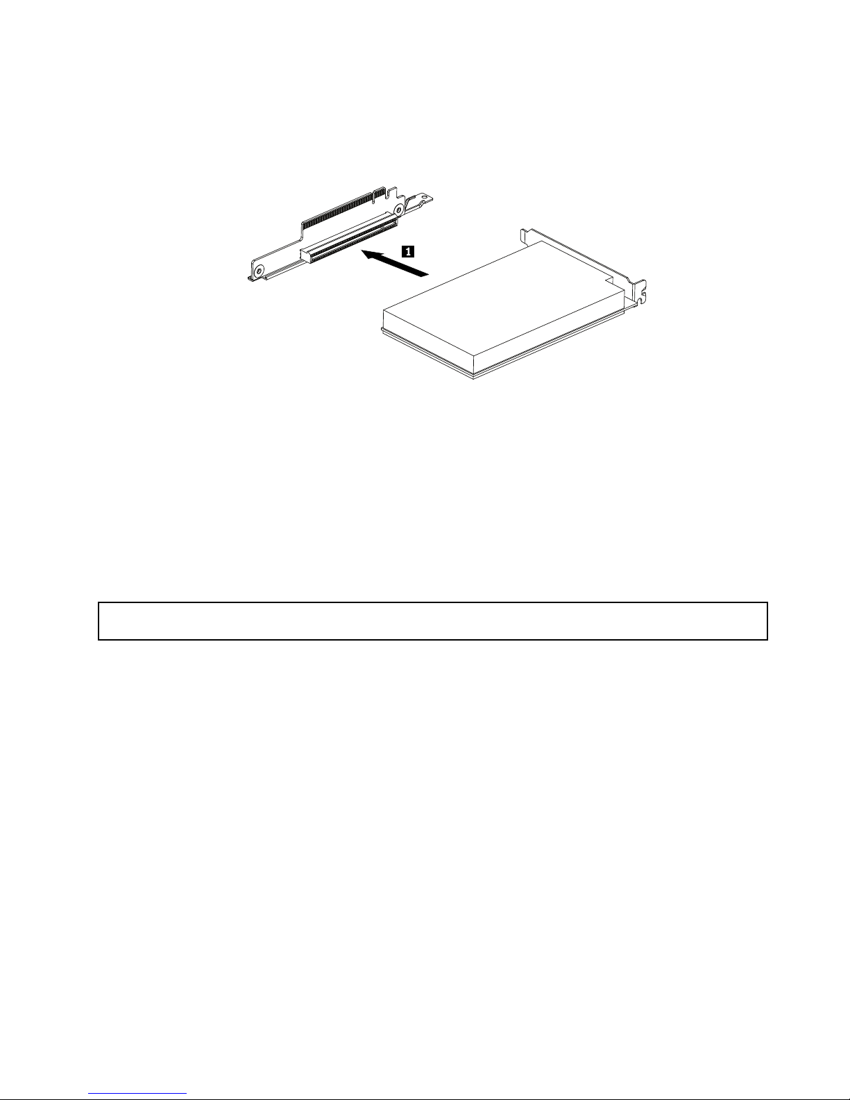
4.InstallthePCIcardintotheslotontherisercardassembly.
Figure24.InstallingaPCIcardintotheslotontherisercardassembly
5.InstalltherisercardassemblyintoanappropriatePCIcardslotonthesystemboard.See“Installing
therisercardassembly”onpage35
.
6.ConnectanycablestothePCIcard.
Whattodonext:
•Toworkwithanotherpieceofhardware,gototheappropriatesection.
•Tocompletetheinstallation,goto“Completingthepartsreplacement”onpage67.
RemovingaPCIcard
Attention:Donotopenyourserverorattemptanyrepairbeforereadingandunderstandingthe“Safetyinformation”
onpageiiiand“Guidelines”onpage19.
ThissectionprovidesinstructionsonhowtoremoveaPCIcard.
ThePCIcardisinstalledontherisercardassembly.ToremoveaPCIcard,dothefollowing:
Note:UseanydocumentationthatcomeswiththePCIcardandfollowthoseinstructionsinadditionto
theinstructionsinthissection.
1.Removeallmediafromthedrivesandturnoffallattacheddevicesandtheserver.Then,disconnectall
powercordsfromelectricaloutletsanddisconnectallcablesthatareconnectedtotheserver.
2.Removetheservercover.See“Removingtheservercover”onpage21.
3.DisconnectanycablesfromthePCIcardoranycablesthatimpedeaccesstotherisercardassembly.
4.RemovetherisercardassemblytogetherwiththeinstalledPCIcard.See“Removingtherisercard
assembly”onpage36.
Chapter5.Installing,removing,orreplacinghardware39
Page 52

5.RemovethePCIcardfromthePCIcardslotontherisercardassembly.
Figure25.RemovingthePCIcardfromtherisercardassembly
IfyouareinstructedtoreturnthePCIcard,followallpackaginginstructionsanduseanypackagingmaterials
thataresuppliedtoyouforshipping.
Whattodonext:
•Toworkwithanotherpieceofhardware,gototheappropriatesection.
•Tocompletetheremovalprocedure,goto“Completingthepartsreplacement”onpage67
.
RemovingorinstallingtheEthernetcard
ThissectionprovidesinstructionsonhowtoremoveorinstalltheEthernetcard.
RemovingtheEthernetcard
Attention:Donotopenyourserverorattemptanyrepairbeforereadingandunderstandingthe“Safetyinformation”
onpageiiiand“Guidelines”onpage19.
ThissectionprovidesinstructionsonhowtoremovetheEthernetcard.
TheEthernetcardisinstalledontherisercardassembly.T oremovetheEthernetcard,dothefollowing:
Note:UseanydocumentationthatcomeswiththeEthernetcardandfollowthoseinstructionsinadditionto
theinstructionsinthissection.
1.Removeallmediafromthedrivesandturnoffallattacheddevicesandtheserver.Then,disconnectall
powercordsfromelectricaloutletsanddisconnectallcablesthatareconnectedtotheserver.
2.Removetheservercover.See“Removingtheservercover”onpage21.
3.Disconnectanycablesthatimpedeaccesstotherisercardassembly.
4.RemovetherisercardassemblytogetherwiththeinstalledEthernetcard.See“Removingtheriser
cardassembly”onpage36
.
5.Referto“RemovingaPCIcard”onpage39andfollowthoseinstructionstoremovetheEthernetcard
fromtherisercardassembly.
6.IfyouareinstructedtoreturntheEthernetcard,followallpackaginginstructionsanduseanypackaging
materialsthataresuppliedtoyouforshipping.
Whattodonext:
•Toworkwithanotherpieceofhardware,gototheappropriatesection.
40ThinkServerUserGuide
Page 53

•Tocompletetheremovalprocedure,goto“Completingthepartsreplacement”onpage67.
InstallingtheEthernetcard
Attention:Donotopenyourserverorattemptanyrepairbeforereadingandunderstandingthe“Safetyinformation”
onpageiii
and“Guidelines”onpage19.
ThissectionprovidesinstructionsonhowtoinstalltheEthernetcardandhowtoinstalltheEthernetcard
driveronWindowsoperatingsystems.
ToinstalltheEthernetcard,dothefollowing:
1.Removeallmediafromthedrivesandturnoffallattacheddevicesandtheserver.Then,disconnectall
powercordsfromelectricaloutletsanddisconnectallcablesthatareconnectedtotheserver.
2.Removetheservercover.See“Removingtheservercover”onpage21.
3.Touchthestatic-protectivepackagethatcontainstheEthernetcardtoanyunpaintedsurfaceonthe
outsideoftheserver.Then,removetheEthernetcardfromthepackage.
4.See“InstallingaPCIcard”onpage38andfollowthoseinstructionstoinstalltheEthernetcard.
Whattodonext:
•Toworkwithanotherpieceofhardware,gototheappropriatesection.
•Tocompletetheinstallation,goto“Completingthepartsreplacement”onpage67
.
OnLinuxoperatingsystems,youdonotneedtoinstallanydevicedriverfortheEthernetcard;onWindows
operatingsystems,youneedtoinstallthedevicedriverfortheEthernetcard.Toinstallthedevicedriver
onWindowsoperatingsystems,dothefollowing:
1.Saveanyopendocumentsandexitallapplications.
2.InserttheThinkServerEasyStartupDVDthatcamewithyourserverintotheDVDdrive.
Note:YoudonotneedtousethedriverdiscthatcamewiththeEthernetcard.
3.Right-clickMyComputerandselectProperties.TheSystemPropertieswindowopens.
4.OntheHardwaretab,clicktheDeviceManagerbutton.TheDeviceManagerwindowopens.
5.ExpandtheNetworkadaptersandthenright-clickoneoftheEthernetcards(PRO/1000PTorthe
yellowquestionmark).
6.SelectUpdateDriver....TheHardwareUpdateWizardprogramopens.
7.SelectInstallthesoftwareautomatically(Recommended)andclickNexttocontinue.
8.Followtheinstructionsonthescreen.
Installing,removing,orreplacinghardwaredevices
Thissectionprovidesinstructionsonhowtoinstall,remove,orreplacehardwaredevicesforyourserver.
Youcanmaintainyourserverbyreplacingthefailinghardwaredevices.Ifyouarereplacingahardware
device,performtheremovalprocedureandthenperformtheinstallationprocedureforthehardwaredevice
thatyouwanttoreplace.
Removingorinstallingthesystemboardbattery
Thissectionprovidesinstructionsonhowtoremoveorinstallthesystemboardbattery.
Chapter5.Installing,removing,orreplacinghardware41
Page 54
Removingthesystemboardbattery
Attention:Donotopenyourserverorattemptanyrepairbeforereadingandunderstandingthe“Safetyinformation”
onpageiiiand“Guidelines”onpage19.
Thissectionprovidesinstructionsonhowtoremovethesystemboardbattery.
Toremovethesystemboardbattery,dothefollowing:
1.Removeallmediafromthedrivesandturnoffallattacheddevicesandtheserver.Then,disconnectall
powercordsfromelectricaloutletsanddisconnectallcablesthatareconnectedtotheserver.
2.Removetheservercover.See“Removingtheservercover”onpage21.
3.Locatethebatteryonthesystemboard.See“Locatingpartsonthesystemboard”onpage15.
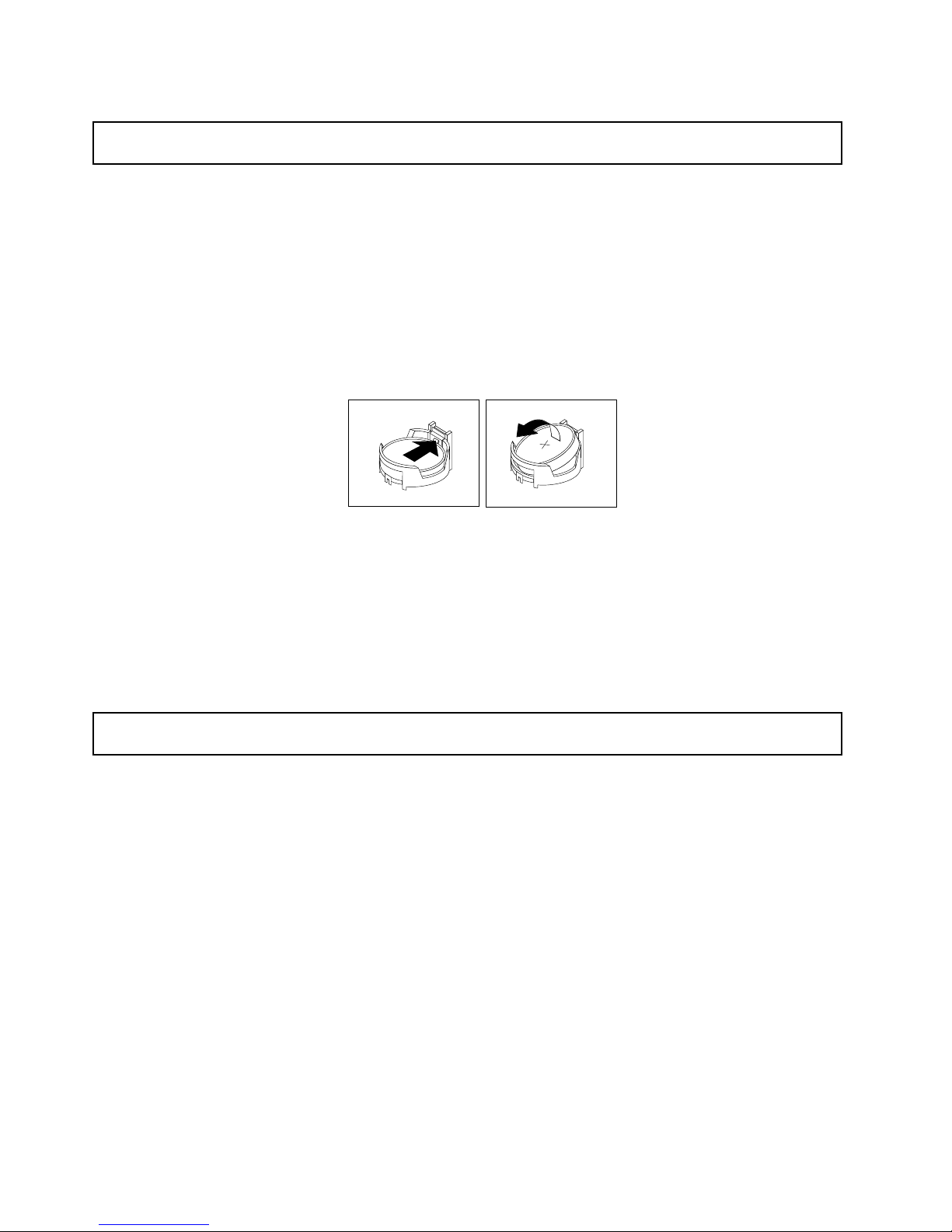
4.Removethesystemboardbattery.
Figure26.Removingthesystemboardbattery
5.Disposeofthebatteryasrequiredbylocalordinancesorregulations.
Whattodonext:
•Toinstallanewsystemboardbattery,see“Installingthesystemboardbattery”onpage42.
•Toworkwithanotherpieceofhardware,gototheappropriatesection.
Installingthesystemboardbattery
Attention:Donotopenyourserverorattemptanyrepairbeforereadingandunderstandingthe“Safetyinformation”
onpageiiiand“Guidelines”onpage19.
Thissectionprovidesinstructionsonhowtoinstallthesystemboardbattery.
Besuretoconsiderthefollowinginformationwhenyoureplacethebatteryintheserver:
•Youmustreplacethebatterywithalithiumbatteryofthesametypefromthesamemanufacturer.
•Afteryoureplacethesystemboardbattery,youmustreconguretheserverandresetthesystemdate
andtime.
•Toavoidpossibledanger,readandfollowthefollowingsafetystatement.
42ThinkServerUserGuide
Page 55
Statement2
DANGER
Dangerofexplosionifbatteryisincorrectlyreplaced.
Whenreplacingthelithiumcoincellbattery,useonlythesameoranequivalenttypethatis
recommendedbythemanufacturer .Thebatterycontainslithiumandcanexplodeifnotproperly
used,handled,ordisposedof.
Donot:
•Throworimmerseintowater
•Heattomorethan100°C(212°F)
•Repairordisassemble
Disposeofthebatteryasrequiredbylocalordinancesorregulations.
Toinstallthesystemboardbattery,dothefollowing:
Note:Followanyspecialhandlingandinstallationinstructionsthatcomewiththereplacementbattery.
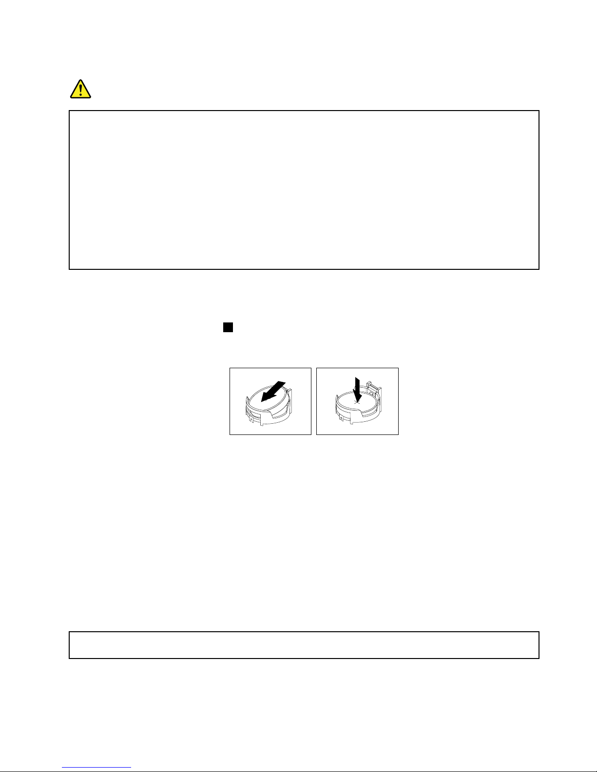
1.Holdthesystemboardbattery1andpositiononesideofthebatteryintoitssocket.Then,pressthe
othersideofthebatteryuntilitsnapsintoplace.
Figure27.Installingthesystemboardbattery
2.Makesurethatthebatteryclipholdsthebatterysecurely.
Whattodonext:
•Toworkwithanotherpieceofhardware,gototheappropriatesection.
•Tocompletetheinstallation,goto“Completingthepartsreplacement”onpage67.Y ouneedtousethe
SetupUtilityprogramandresettheconguration,suchasthesystemdateandtimeandpasswords.See
“StartingtheSetupUtilityprogram”onpage72
fordetails.
RemovingorinstallingtheRAIDcontroller
ThissectionprovidesinstructionsonhowtoremoveorinstalltheRAIDcontroller.
RemovingtheRAIDcontroller
Attention:Donotopenyourserverorattemptanyrepairbeforereadingandunderstandingthe“Safetyinformation”
onpageiiiand“Guidelines”onpage19.
ThissectionprovidesinstructionsonhowtoremovetheRAIDcontrollerinstalledinyourserver.
Chapter5.Installing,removing,orreplacinghardware43
Page 56

Notes:
1.UseanydocumentationthatcomeswiththeRAIDcontrollerandfollowthoseinstructionsinadditionto
theinstructionsinthissection.
2.Whenyoudisconnectthepowersourcefromtheserver,youlosetheabilitytoviewtheLEDsbecause
theLEDsarenotlitwhenthepowersourceisremoved.Beforeyoudisconnectthepowersource,make
anoteofwhichLEDsarelit,includingtheLEDsthatarelitonthefrontcontrolpanel.
TheRAIDcontrollerisinstalledontherisercardassembly.T oremovetheRAIDcontroller,dothefollowing:
1.Removeallmediafromthedrivesandturnoffallattacheddevicesandtheserver.Then,disconnectall
powercordsfromelectricaloutletsanddisconnectallcablesthatareconnectedtotheserver.
2.Removetheservercover.See“Removingtheservercover”onpage21.
3.Pressthetabsonbothsidesoftheconnectoronthesignalcabletowardseachotherandremovethe
cablefromtheRAIDcontroller.
4.DisconnectanyothercablesfromtheRAIDcontrolleroranycablesthatimpedeaccesstotheriser
cardassembly.
5.RemovetherisercardassemblytogetherwiththeinstalledRAIDcontroller.See“Removingtheriser
cardassembly”onpage36.
6.Referto“RemovingaPCIcard”onpage39andfollowthoseinstructionstoremovetheRAIDcontroller
fromtherisercardassembly.
Note:DependingonyourRAIDcontroller,ifnecessary,removetheRAIDbatteryfromtheRAID
controllerbyremovingthescrewsthatsecurethebatteryonthecontrolleranddisconnectinganycables.
7.IfyouareinstructedtoreturntheRAIDcontroller,followallpackaginginstructionsanduseany
packagingmaterialsthataresuppliedtoyouforshipping.
Whattodonext:
•Toworkwithanotherpieceofhardware,gototheappropriatesection.
•Tocompletetheremovalprocedure,goto“Completingthepartsreplacement”onpage67.
InstallingtheThinkServer8708ELPSASRAIDAdapter
Attention:Donotopenyourserverorattemptanyrepairbeforereadingandunderstandingthe“Safetyinformation”
onpageiii
and“Guidelines”onpage19.
ThissectionprovidesinstructionsonhowtoinstalltheThinkServer8708ELPSASRAIDAdapter(hereafter
referredtoastheRAIDcontrollerwithinthissection).
ToinstalltheRAIDcontroller,dothefollowing:
Note:UseanydocumentationthatcomeswiththeRAIDcontrollerandfollowthoseinstructionsinaddition
totheinstructionsinthissection.
1.Removeallmediafromthedrivesandturnoffallattacheddevicesandtheserver.Then,disconnectall
powercordsfromelectricaloutletsanddisconnectallcablesthatareconnectedtotheserver.
2.Removetheservercover.See“Removingtheservercover”onpage21.
3.Touchthestatic-protectivepackagethatcontainstheRAIDcontrollertoanyunpaintedsurfaceonthe
outsideoftheserver.Then,removetheRAIDcontrollerfromthepackage.
4.DependingonyourRAIDcontroller,youmightneedtoinstallaThinkServer8708ELPSASRAID
adapterbattery(hereafterreferredtoasthebatterycardassembly)ontheRAIDcontroller.Thebattery
cardassemblymountsdirectlytotheRAIDcontrollerthroughasmallboard-to-boardconnector
(daughtercard).
44ThinkServerUserGuide
Page 57

Notes:
a.ThebatterycardassemblyprotectstheintegrityofthecacheddataontheRAIDcontrollerby
providingbackuppowerupto72hoursinthecaseofacompleteacpowerfailureorabriefpower
outage.Ithasbuilt-infunctionalitytochargethebatterypackautomaticallyandtocommunicate
batterystatusinformationsuchasvoltage,temperature,andcurrenttoyourserver.Italsoprovides
aninexpensivealternativetousinganuninterruptiblepowersupply,andasecondleveloffault
tolerancewhenusedinconjunctionwithanuninterruptiblepowersupply.Formoreinformationabout
thebatterycardassembly,seeAppendixA“RAIDbatterycardassembly”onpage99
.
b.Thebatterycardassemblyoptionkitcontainsauserguide,thebatterycardassembly,andthree
Phillips-headscrews.Donotremovethebatterycardassemblyfromtheantistaticshipping
containeruntilyouarereadytoinstallit.Whenyouremovethebatterycardassemblyfromyour
server,placeitinitsoriginalcontainer.
c.ChecktheappropriatesupportWebsitesforthelatestupdatesforyourbasicinput/outputsystem
(BIOS)code,utilityprograms,devicedrivers,andothersoftwareapplications.Followtheinstructions
providedbyyourServiceProvidertodownloadandinstallupdates.
d.Itisrecommendedthatyoureplacethebatterypackonthebatterycardassemblyannuallyorafter
500rechargingcycles,whichevercomesrst.
e.Thetemperatureofthebatterycardassemblyisgenerally15-20°C(59-68°F)higherthanthe
ambienttemperatureduringfastcharge.Therefore,tocompleteafastchargecycle,theambient
temperatureshouldbelowerthan45°C(113°F).Iftheambienttemperatureexceeds45°C(113°F),
thefastchargecyclewillterminateprematurely,thuspreventingthebatterycardassemblyfrom
reachingafullychargedstate.
Attention:
•WhenattachingthebatterycardassemblytoaPCIExpressslot,centerthePhillips-headscrew
drivertoavoiddamagingthescrewheadanddonotover-tightenthescrewsasyoumightdamage
thebatterycardassembly.
•Thebatteryinthebatterycardassemblymustrechargeforatleastsixhoursduringfastcharge
undernormaloperatingconditions.
ToinstallthebatterycardassemblyontotheRAIDcontroller,dothefollowing:
Chapter5.Installing,removing,orreplacinghardware45
Page 58
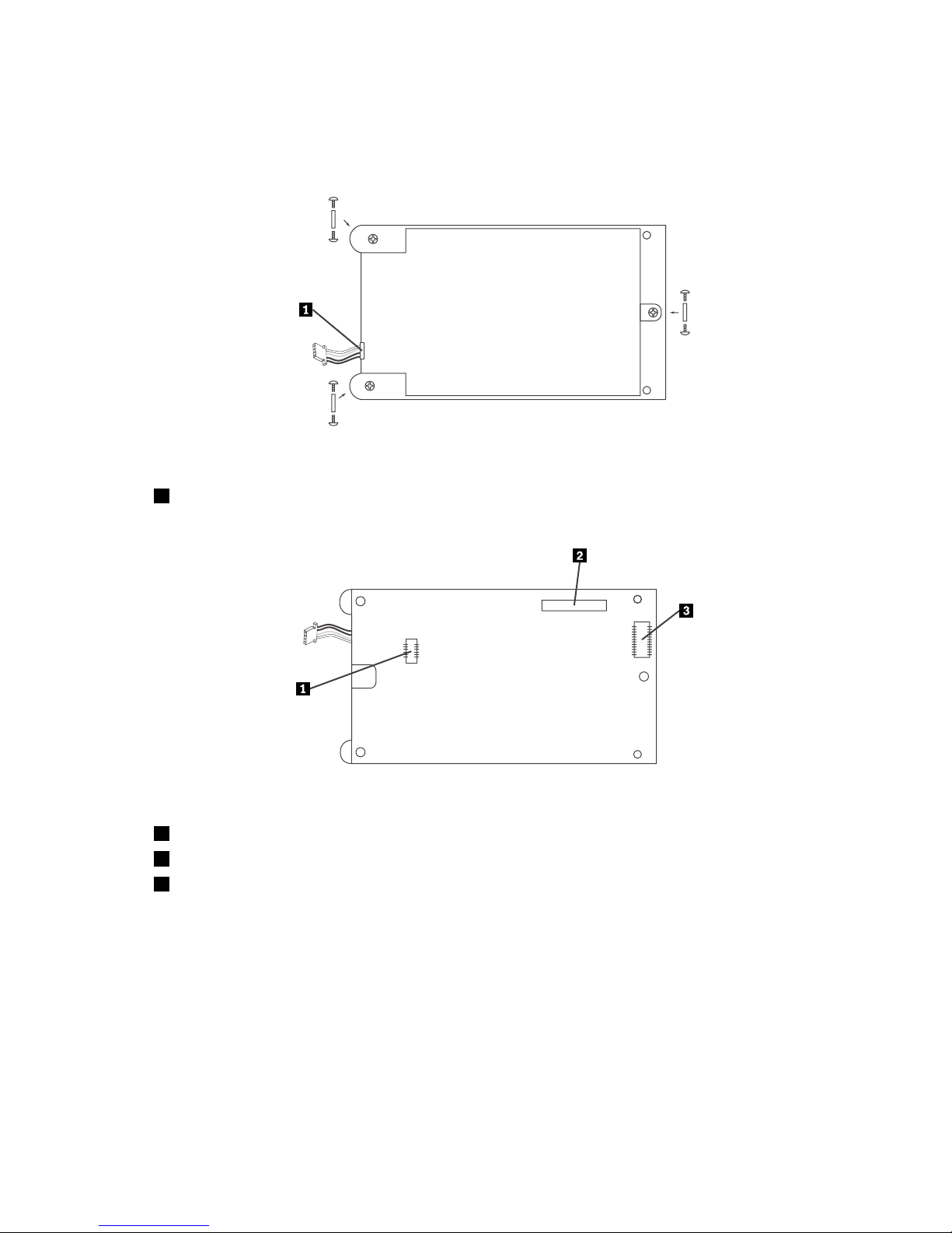
a.Notethetopviewandthebottomviewofthebatterycardassembly.Then,insertthebatterypack
harnessconnectorintothe5-pinJ3batterypackharnessconnectoronthebacksideofthebattery
cardassembly.Formoreinformation,refertothefollowingillustrations.
Figure28.Topviewofthebatterycardassembly
1Batterypackharness
Figure29.Bottomviewofthebatterycardassembly
1J3batterypackharnessconnector
2J1connector
3J2board-to-boardconnector
b.Withthefrontsideup,placetheRAIDcontrolleronaat,clean,static-freesurface.
46ThinkServerUserGuide
Page 59
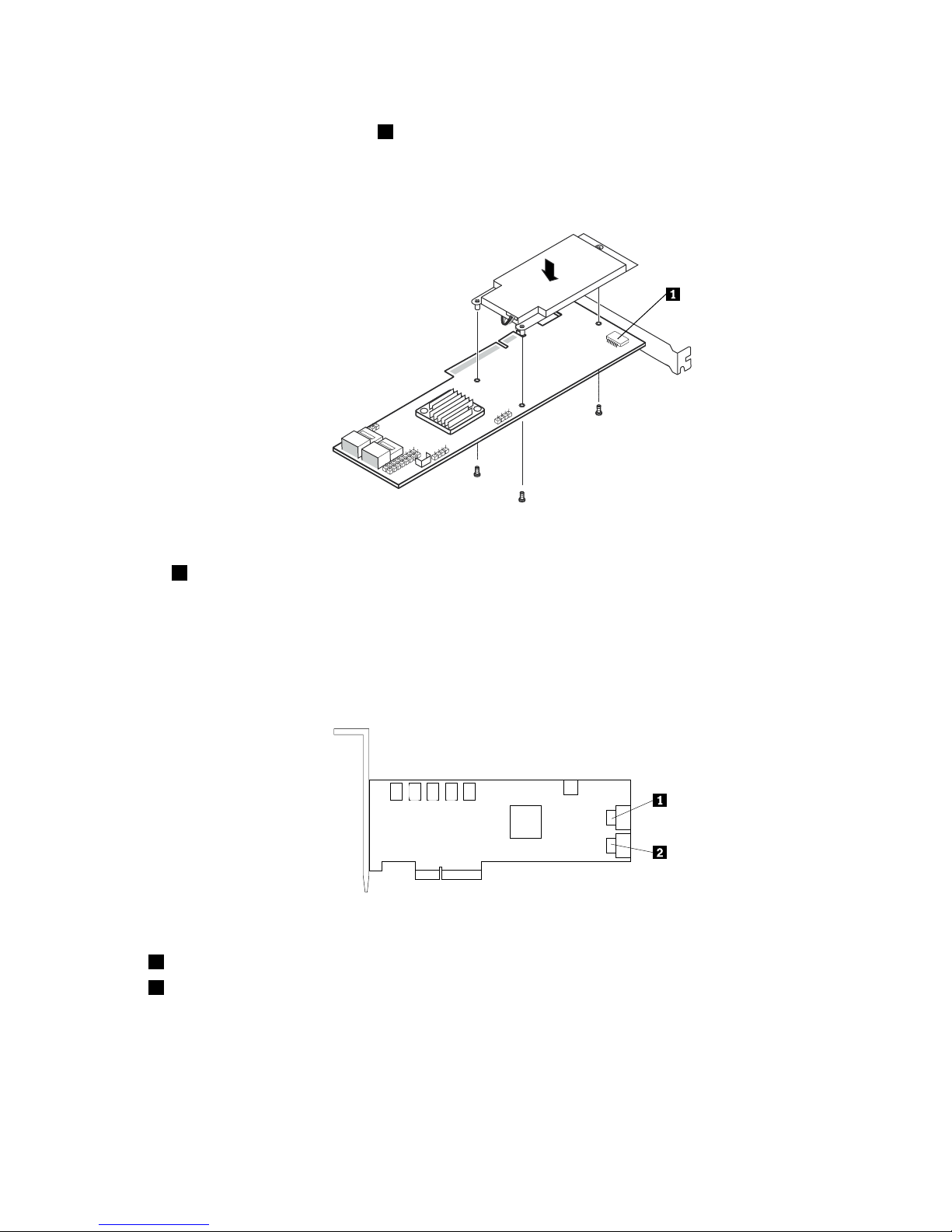
c.HoldthebatterycardassemblywiththebatterysideupandtheJ2board-to-boardconnectorlining
upwiththeJ7BBUconnector1ontheRAIDcontroller.Carefullypressthebatterycardassembly
ontotheRAIDcontrollersothatthetwoconnectorsarermlyjoined.Then,securethebattery
cardassemblytotheRAIDcontrollerwiththethreescrewsandthestandoffsthatcomewiththe
batterycardassemblyaccessorykit.
Figure30.Installingthebatterycardassembly
1J7BBUconnector
5.See“InstallingaPCIcard”onpage38andfollowthoseinstructionstoinstalltheRAIDcontroller.
6.ConnecttheminiSASsignalcabletotheRAIDcontrollerandminiSASsignalcableconnectoronthe
backplane.See“Locatingconnectorsonthebackplane”onpage18
Note:Usethe440mm(17.32inches)miniSASsignalcable.
Figure31.ConnectingtheminiSASsignalcable
1Ports0-3
2Ports4-7(reservedforuse)
Whattodonext:
•Toworkwithanotherpieceofhardware,gototheappropriatesection.
•Tocompletetheinstallation,goto“Completingthepartsreplacement”onpage67
.
Chapter5.Installing,removing,orreplacinghardware47
Page 60

InstallingtheThinkServer8708EM2RAIDAdapter
Attention:Donotopenyourserverorattemptanyrepairbeforereadingandunderstandingthe“Safetyinformation”
onpageiiiand“Guidelines”onpage19.
ThistopicprovidesinstructionsonhowtoinstalltheThinkServer8708EM2RAIDAdapter(hereafterreferred
toastheRAIDcontrollerwithinthistopic)andthebatterycardassemblyforthisRAIDcontroller.
ToinstalltheRAIDcontroller,dothefollowing:
Note:UseanydocumentationthatcomeswiththeRAIDcontrollerandfollowthoseinstructionsinaddition
totheinstructionsinthistopic.
1.Removeallmediafromthedrivesandturnoffallattacheddevicesandtheserver.Then,disconnectall
powercordsfromelectricaloutletsanddisconnectallcablesthatareconnectedtotheserver.
2.Removetheservercover.See“Removingtheservercover”onpage21.
3.Removetherisercardassembly.See“Removingtherisercardassembly”onpage36.
4.Touchthestatic-protectivepackagethatcontainstheRAIDcontrollertoanyunpaintedsurfaceonthe
outsideoftheserver.Then,removetheRAIDcontrollerfromthepackage.
5.DependingonyourRAIDcontroller,youmightneedtoinstallaThinkServer8708EM2RAIDAdapter
Battery(hereafterreferredtoasthebatterycardassembly)ontheRAIDcontroller.Thebattery
cardassemblymountsdirectlytotheRAIDcontrollerthroughasmallboard-to-boardconnector
(daughtercard).
Notes:
a.ThebatterycardassemblyprotectstheintegrityofthecacheddataontheRAIDcontrollerby
providingbackuppowerupto72hoursinthecaseofacompleteacpowerfailureorabriefpower
outage.Ithasbuilt-infunctionalitytochargethebatterypackautomaticallyandtocommunicate
batterystatusinformationsuchasvoltage,temperature,andcurrenttoyourserver.Italsoprovides
aninexpensivealternativetousinganuninterruptiblepowersupply,andasecondleveloffault
tolerancewhenusedinconjunctionwithanuninterruptiblepowersupply.Formoreinformationabout
thebatterycardassembly,seeAppendixA“RAIDbatterycardassembly”onpage99
.
b.Thebatterycardassemblyoptionkitcontainsauserguide,thebatterycardassembly,andthree
Phillips-headscrews.Donotremovethebatterycardassemblyfromtheantistaticshipping
containeruntilyouarereadytoinstallit.Whenyouremovethebatterycardassemblyfromyour
server,placeitinitsoriginalcontainer.
c.ChecktheappropriatesupportWebsitesforthelatestupdatesforyourbasicinput/outputsystem
(BIOS)code,utilityprograms,devicedrivers,andothersoftwareapplications.Followtheinstructions
providedbyyourServiceProvidertodownloadandinstallupdates.
d.Itisrecommendedthatyoureplacethebatterypackonthebatterycardassemblyannuallyorafter
500rechargingcycles,whichevercomesrst.
e.Thetemperatureofthebatterycardassemblyisgenerally15-20°C(59-68°F)higherthanthe
ambienttemperatureduringfastcharge.Therefore,tocompleteafastchargecycle,theambient
temperatureshouldbelowerthan45°C(113°F).Iftheambienttemperatureexceeds45°C(113°F),
thefastchargecyclewillterminateprematurely,thuspreventingthebatterycardassemblyfrom
reachingafullychargedstate.
Attention:
•WhenattachingthebatterycardassemblytoaPCIExpressslot,centerthePhillips-headscrew
drivertoavoiddamagingthescrewheadanddonotover-tightenthescrewsasyoumightdamage
thebatterycardassembly.
•Thebatteryinthebatterycardassemblymustrechargeforatleastsixhoursduringfastcharge
undernormaloperatingconditions.
48ThinkServerUserGuide
Page 61
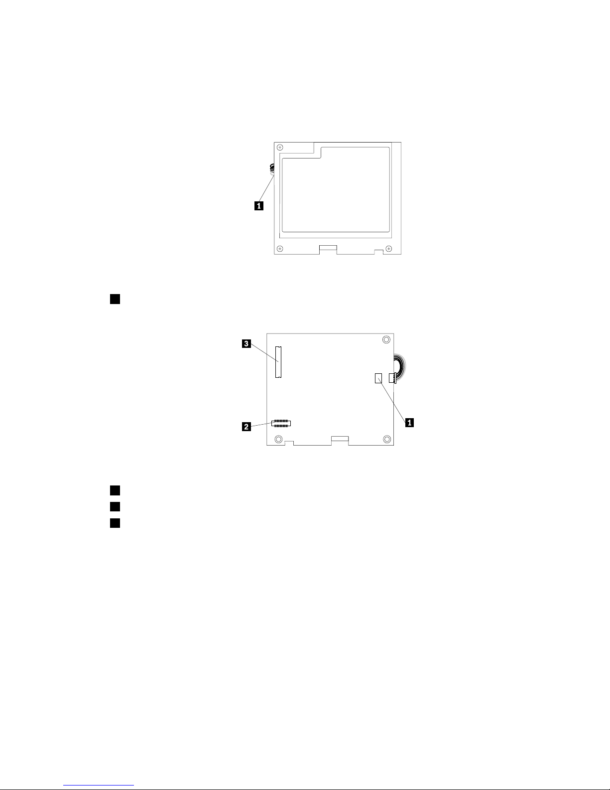
ToinstallthebatterycardassemblyontotheRAIDcontroller,dothefollowing:
a.Notethetopviewandbottomviewofthebatterycardassembly.Then,insertthebatterypack
harnessconnectorintotheJ4batterypackharnessconnectoronthebacksideofthebatterycard
assembly.Formoreinformation,refertothefollowingillustrations.
Figure32.Topviewofthebatterycardassembly
1Batterypackharness
Figure33.Bottomviewofthebatterycardassembly
1J4batterypackharnessconnector
2J5board-to-boardconnector
3J2connector
b.Withthefrontsideup,placetheRAIDcontrolleronaat,clean,static-freesurface.
Chapter5.Installing,removing,orreplacinghardware49
Page 62
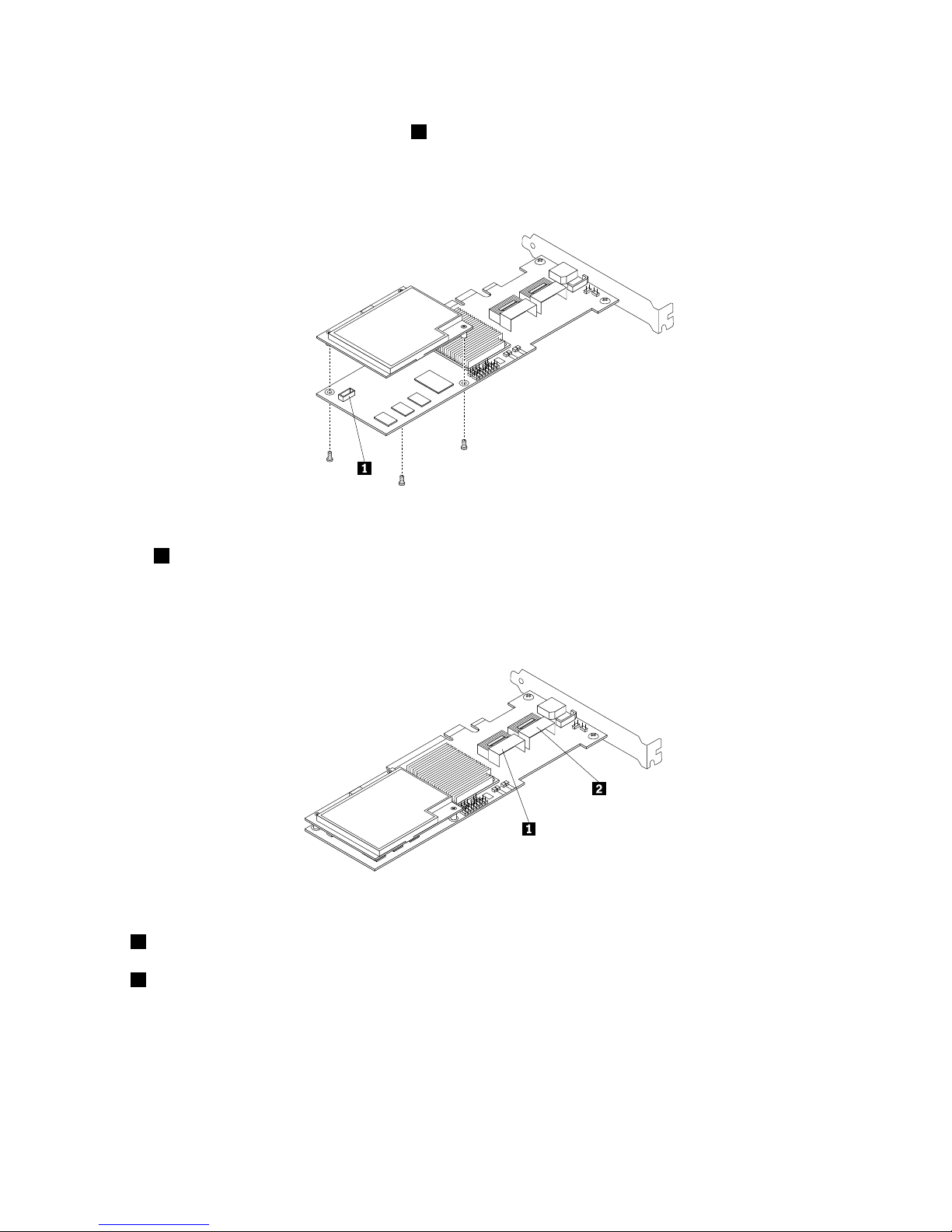
c.HoldthebatterycardassemblywiththebatterysideupandtheJ5board-to-boardconnector
liningupwiththeJ10BBUconnector1ontheRAIDcontroller.Carefullypressthebatterycard
assemblyontotheRAIDcontrollersothatthetwoconnectorsarermlyjoined.Then,securethe
batterycardassemblytotheRAIDcontrollerwiththethreescrewsandthestandoffsthatcome
withthebatterycardassemblyaccessorykit.
Figure34.InstallingthebatterycardassemblyontotheRAIDcontroller
1J10BBUconnector
6.ConnecttheminiSASsignalcabletoports0-3ontheRAIDcontroller.
Note:Usethe400mm(15.75inches)miniSASsignalcable.
Figure35.ConnectingtheminiSASsignalcabletotheRAIDcontroller
1Ports0-3
2Ports4-7(reservedforuse)
50ThinkServerUserGuide
Page 63
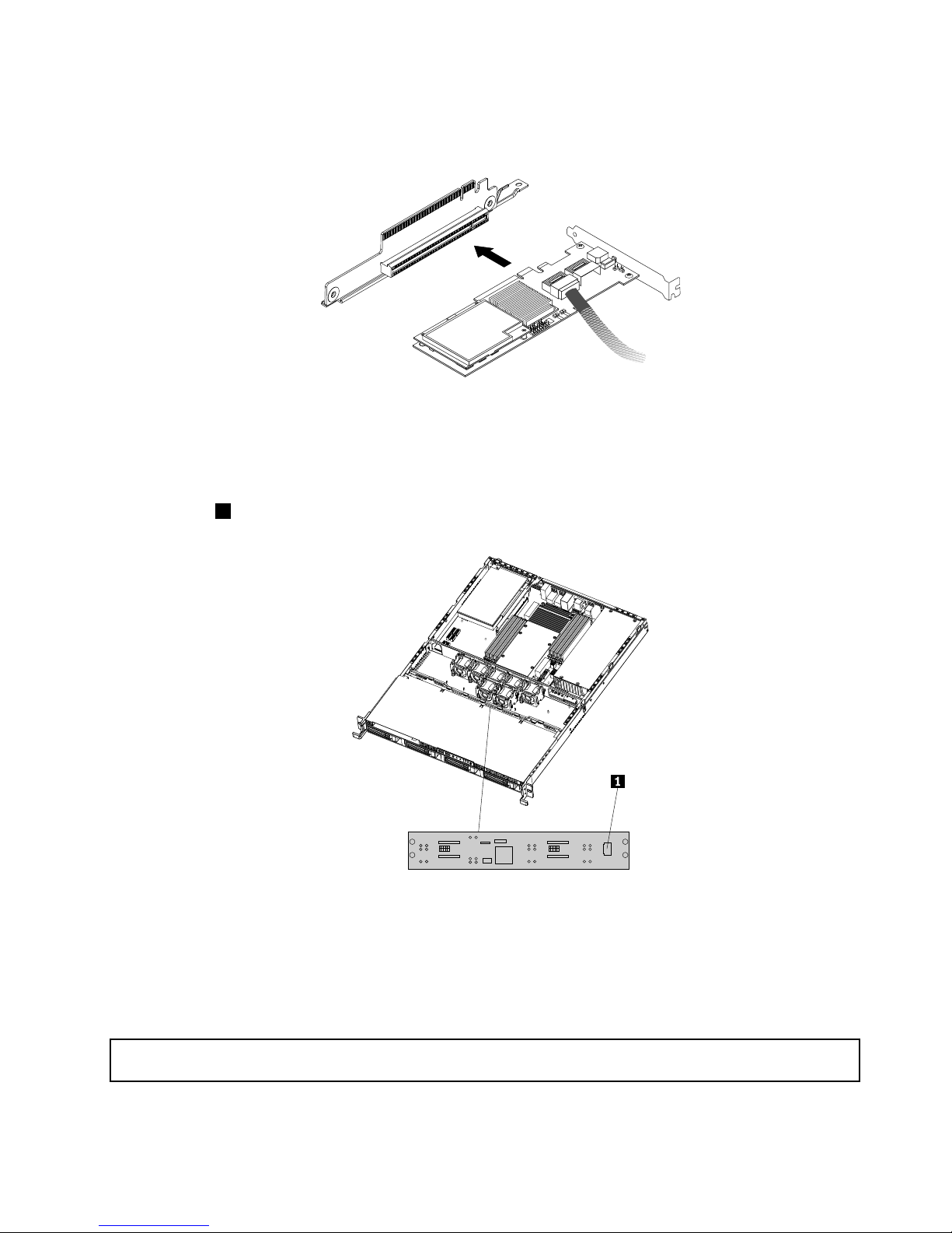
7.InstalltheRAIDcontrollerintoanappropriatePCIcardslotontherisercardassembly.Then,install
thescrewtosecuretheRAIDcontrollerinplace.
Figure36.InstallingtheRAIDcontrollerintothePCIcardslotontherisercardassembly
8.InstalltherisercardassemblywiththeRAIDcontrollerintoanappropriatePCIcardslotonthesystem
board.
9.Connecttheotherendofthe400mm(15.75inches)miniSASsignalcabletotheminiSASsignalcable
connector1onthebackplaneofyourserver.
Figure37.MiniSASsignalcableconnectoronthebackplane
Whattodonext:
•Toworkwithanotherpieceofhardware,gototheappropriatesection.
•Tocompletetheinstallation,goto“Completingthepartsreplacement”onpage67
.
InstallingtheThinkServerRAID700Adapter
Attention:Donotopenyourserverorattemptanyrepairbeforereadingandunderstandingthe“Safetyinformation”
onpageiii
and“Guidelines”onpage19.
Chapter5.Installing,removing,orreplacinghardware51
Page 64

ThistopicprovidesinstructionsonhowtoinstalltheThinkServerRAID700Adapter(hereafterreferredtoas
theRAIDcontrollerwithinthistopic)andthebatterycardassemblyforthisRAIDcontroller.
ToinstalltheRAIDcontroller,dothefollowing:
Note:UseanydocumentationthatcomeswiththeRAIDcontrollerandfollowthoseinstructionsinaddition
totheinstructionsinthistopic.
1.Removeallmediafromthedrivesandturnoffallattacheddevicesandtheserver.Then,disconnectall
powercordsfromelectricaloutletsanddisconnectallcablesthatareconnectedtotheserver.
2.Removetheservercover.See“Removingtheservercover”onpage21.
3.Removetherisercardassembly.See“Removingtherisercardassembly”onpage36.
4.Touchthestatic-protectivepackagethatcontainstheRAIDcontrollertoanyunpaintedsurfaceonthe
outsideoftheserver.Then,removetheRAIDcontrollerfromthepackage.
5.DependingonyourRAIDcontroller,youmightneedtoinstallaThinkServerRAID700AdapterBattery
(hereafterreferredtoasthebatterycardassembly)ontheRAIDcontroller.Thebatterycardassembly
mountsdirectlytotheRAIDcontrollerthroughasmallboard-to-boardconnector(daughtercard).
Notes:
a.ThebatterycardassemblyprotectstheintegrityofthecacheddataontheRAIDcontrollerby
providingbackuppowerupto72hoursinthecaseofacompleteacpowerfailureorabriefpower
outage.Ithasbuilt-infunctionalitytochargethebatterypackautomaticallyandtocommunicate
batterystatusinformationsuchasvoltage,temperature,andcurrenttoyourserver.Italsoprovides
aninexpensivealternativetousinganuninterruptiblepowersupply,andasecondleveloffault
tolerancewhenusedinconjunctionwithanuninterruptiblepowersupply.Formoreinformationabout
thebatterycardassembly,seeAppendixA“RAIDbatterycardassembly”onpage99
.
b.Thebatterycardassemblyoptionkitcontainsauserguide,thebatterycardassembly,andthree
Phillips-headscrews.Donotremovethebatterycardassemblyfromtheantistaticshipping
containeruntilyouarereadytoinstallit.Whenyouremovethebatterycardassemblyfromyour
server,placeitinitsoriginalcontainer.
c.ChecktheappropriatesupportWebsitesforthelatestupdatesforyourbasicinput/outputsystem
(BIOS)code,utilityprograms,devicedrivers,andothersoftwareapplications.Followtheinstructions
providedbyyourServiceProvidertodownloadandinstallupdates.
d.Itisrecommendedthatyoureplacethebatterypackonthebatterycardassemblyannuallyorafter
500rechargingcycles,whichevercomesrst.
e.Thetemperatureofthebatterycardassemblyisgenerally15-20°C(59-68°F)higherthanthe
ambienttemperatureduringfastcharge.Therefore,tocompleteafastchargecycle,theambient
temperatureshouldbelowerthan45°C(113°F).Iftheambienttemperatureexceeds45°C(113°F),
thefastchargecyclewillterminateprematurely,thuspreventingthebatterycardassemblyfrom
reachingafullychargedstate.
Attention:
•WhenattachingthebatterycardassemblytoaPCIExpressslot,centerthePhillips-headscrew
drivertoavoiddamagingthescrewheadanddonotover-tightenthescrewsasyoumightdamage
thebatterycardassembly.
•Thebatteryinthebatterycardassemblymustrechargeforatleastsixhoursduringfastcharge
undernormaloperatingconditions.
ToinstallthebatterycardassemblyontotheRAIDcontroller,dothefollowing:
52ThinkServerUserGuide
Page 65
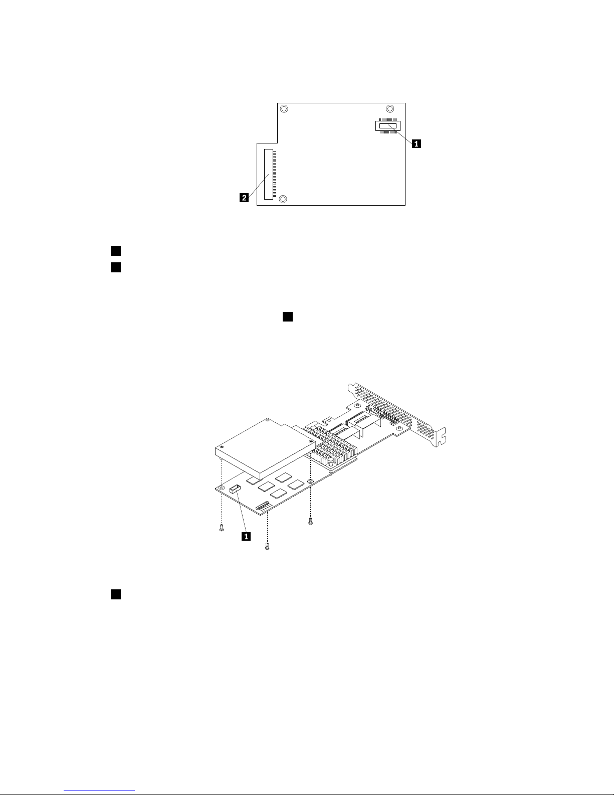
a.Notethebottomviewofthebatterycardassembly.
Figure38.Bottomviewofthebatterycardassembly
1J1board-to-boardconnector
2J2remoteconnector(reservedforuse)
b.Withthefrontsideup,placetheRAIDcontrolleronaat,clean,static-freesurface.
c.HoldthebatterycardassemblywiththebatterysideupandtheJ1board-to-boardconnector
liningupwiththeJ6B1BBUconnector
1ontheRAIDcontroller.Carefullypressthebatterycard
assemblyontotheRAIDcontrollersothatthetwoconnectorsarermlyjoined.Then,securethe
batterycardassemblytotheRAIDcontrollerwiththethreescrewsandthestandoffsthatcome
withthebatterycardassemblyaccessorykit.
Figure39.InstallingthebatterycardassemblyontotheRAIDcontroller
1J6B1BBUconnector
Chapter5.Installing,removing,orreplacinghardware53
Page 66
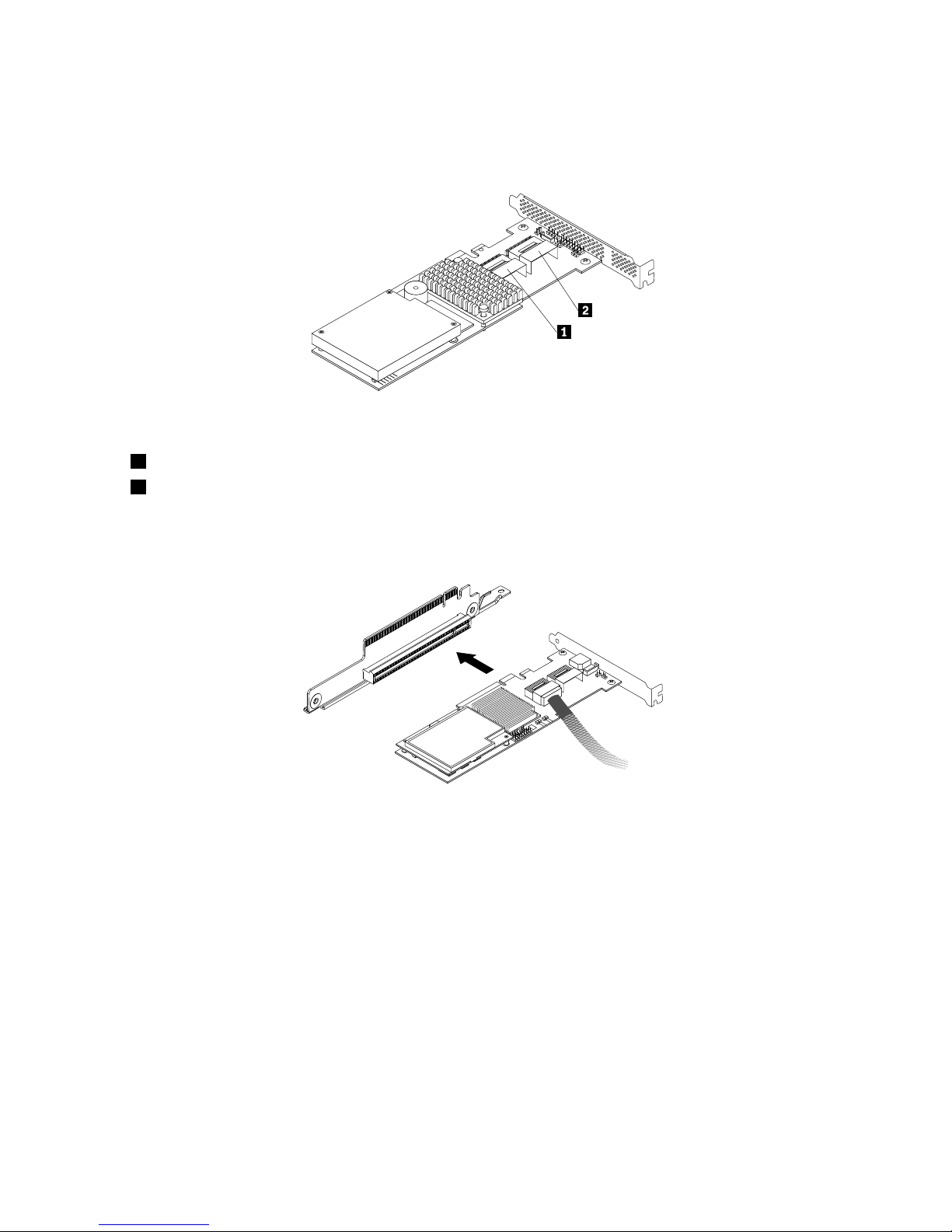
6.ConnecttheminiSASsignalcabletoports0-3ontheRAIDcontroller.
Note:Usethe400mm(15.75inches)miniSASsignalcable.
Figure40.ConnectingtheminiSASsignalcabletotheRAIDcontroller
1Ports0-3
2Ports4-7(reservedforuse)
7.InstalltheRAIDcontrollerintoanappropriatePCIcardslotontherisercardassembly.Then,install
thescrewtosecuretheRAIDcontrollerinplace.
Figure41.InstallingtheRAIDcontrollerintothePCIcardslotontherisercardassembly
8.InstalltherisercardassemblywiththeRAIDcontrollerintoanappropriatePCIcardslotonthesystem
board.
54ThinkServerUserGuide
Page 67
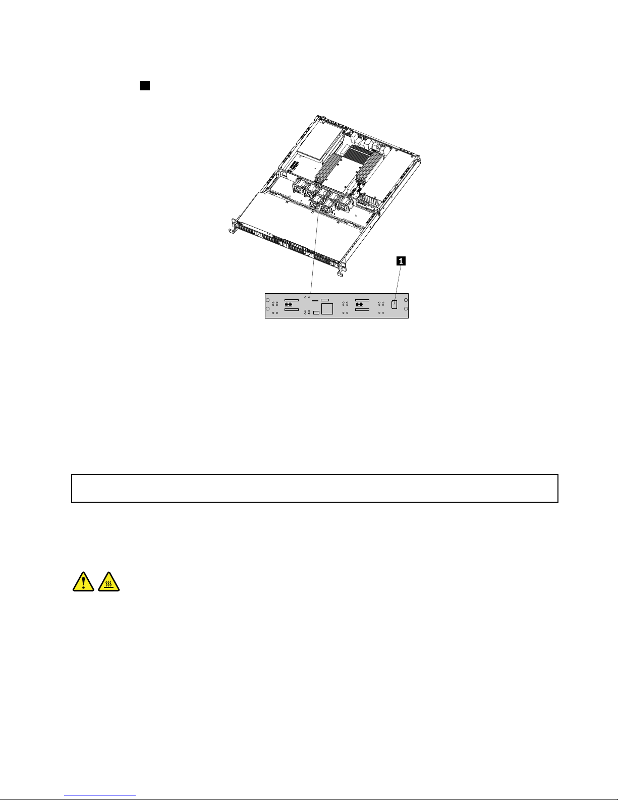
9.Connecttheotherendofthe400mm(15.75inches)miniSASsignalcabletotheminiSASsignalcable
connector1onthebackplaneofyourserver.
Figure42.MiniSASsignalcableconnectoronthebackplane
Whattodonext:
•Toworkwithanotherpieceofhardware,gototheappropriatesection.
•Tocompletetheinstallation,goto“Completingthepartsreplacement”onpage67.
Removingorinstallingtheheatsinkassembly
Thissectionprovidesinstructionsonhowtoremoveorinstalltheheatsinkassembly.
Removingtheheatsinkassembly
Attention:Donotopenyourserverorattemptanyrepairbeforereadingandunderstandingthe“Safetyinformation”
onpageiii
and“Guidelines”onpage19.
Thissectionprovidesinstructionsonhowtoremovetheheatsinkassembly.
CAUTION:
Theheatsinkassemblymightbeveryhot.T urnofftheserverandwaitthreetoveminutestoletthe
servercoolbeforeremovingtheservercover.
Toremovetheheatsinkassembly,dothefollowing:
1.Removeallmediafromthedrivesandturnoffallattacheddevicesandtheserver.Then,disconnectall
powercordsfromelectricaloutletsanddisconnectallcablesthatareconnectedtotheserver.
2.Removetheservercover.SeeRemovingtheservercover.
Chapter5.Installing,removing,orreplacinghardware55
Page 68
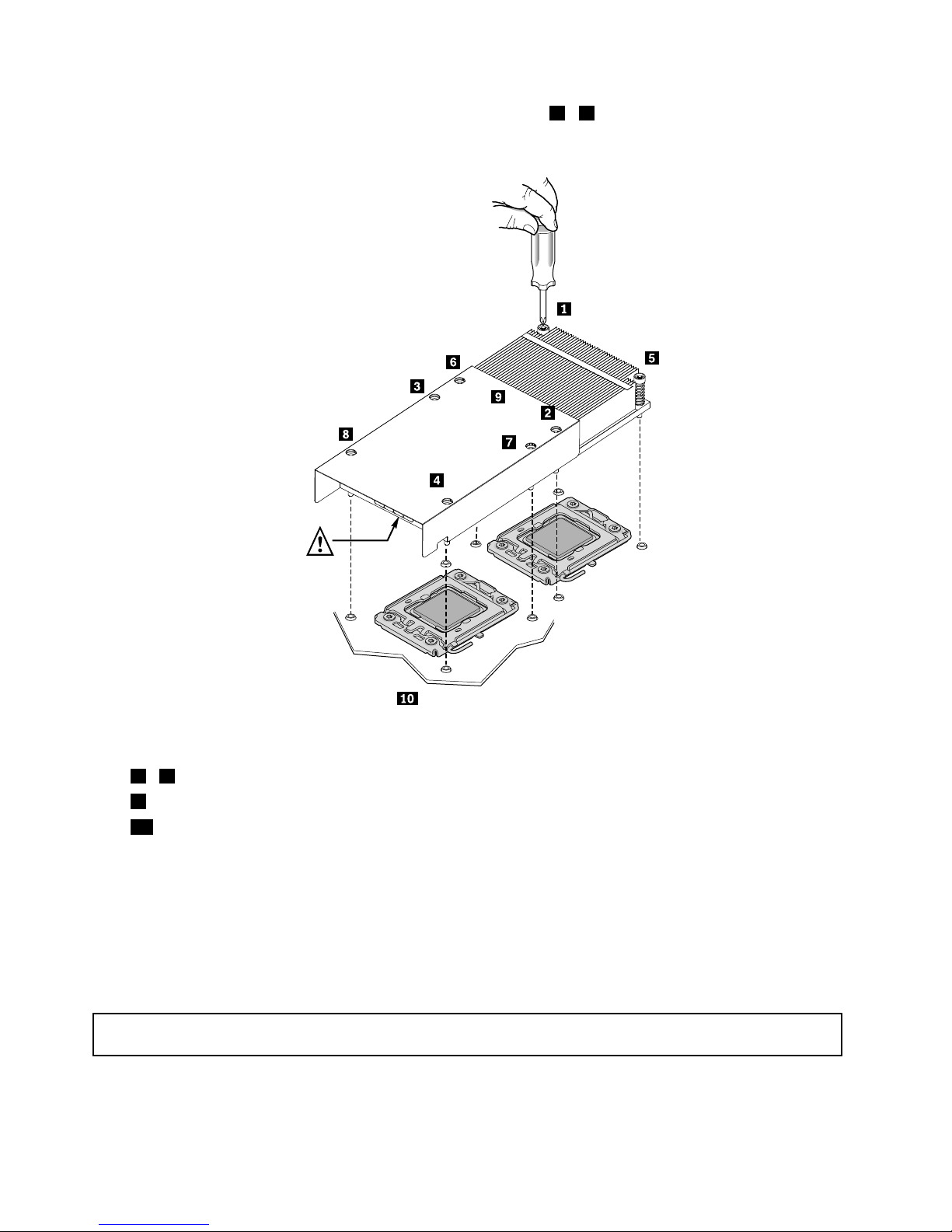
3.Removetheeightscrewsthatsecuretheheatsinkassembly1-8andgentlyliftouttheheatsink
assembly.
Figure43.Removingtheheatsinkassembly
1-8Screws
9Airow
10Indicatesthefrontofthechassis
4.Ifyouareinstructedtoreturntheheatsinkassembly,followallpackaginginstructionsanduseany
packagingmaterialsthataresuppliedtoyouforshipping.
Whattodonext:
•Toworkwithanotherpieceofhardware,gototheappropriatesection.
•Toinstalltheheatsinkassembly,see“Installingtheheatsinkassembly”onpage56.
Installingtheheatsinkassembly
Attention:Donotopenyourserverorattemptanyrepairbeforereadingandunderstandingthe“Safetyinformation”
onpageiiiand“Guidelines”onpage19.
Thissectionprovidesinstructionsonhowtoinstalltheheatsinkassembly.
56ThinkServerUserGuide
Page 69
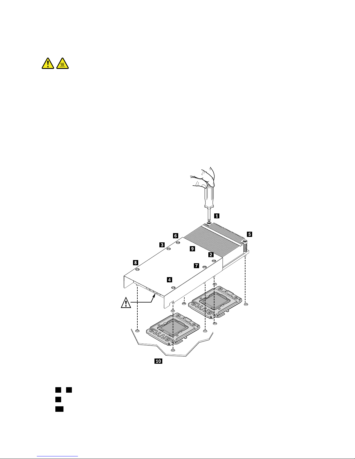
CAUTION:
Theheatsinkandmicroprocessormightbeveryhot.T urnofftheserverandwaitthreetoveminutes
tolettheservercoolbeforeremovingtheservercover.
Toinstalltheheatsinkassembly,dothefollowing:
1.Removeallmediafromthedrivesandturnoffallattacheddevicesandtheserver.Then,disconnectall
powercordsfromelectricaloutletsanddisconnectallcablesthatareconnectedtotheserver.
2.Removetheservercover.See“Removingtheservercover”onpage21.
3.Positiontheheatsinkassemblyinplacebyaligningtheretainingscrewsontheheatsinkassemblywith
thecorrespondingholesinthesystemboard.Then,tightentheeightscrewsfollowingthenumerical
sequenceasshownbelowtosecuretheheatsinkassemblyonthesystemboard.
Figure44.Installingtheheatsinkassembly
1-8Screws
9Airow
10Indicatesthefrontofthechassis
Chapter5.Installing,removing,orreplacinghardware57
Page 70
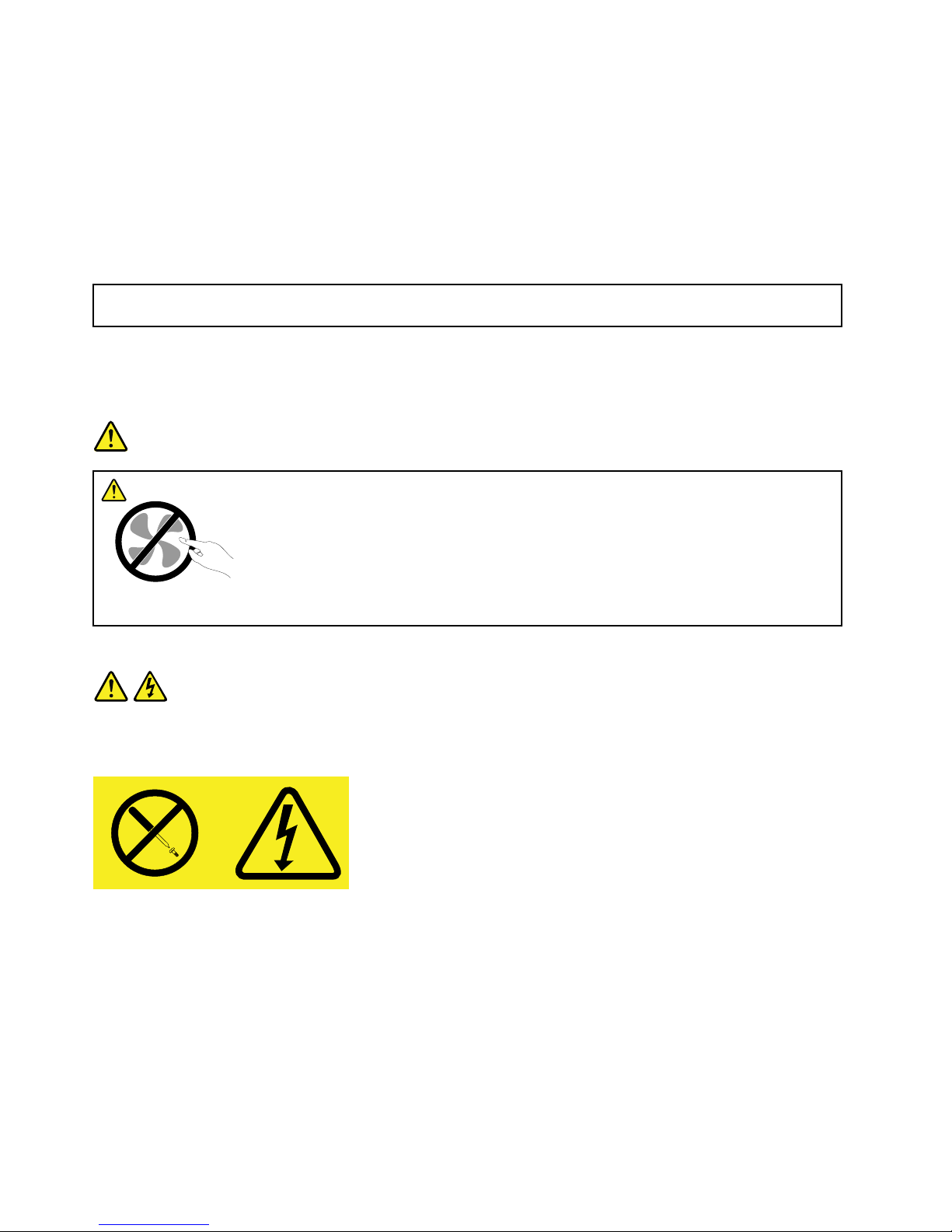
Whattodonext:
•Toworkwithanotherpieceofhardware,gototheappropriatesection.
•Tocompletetheinstallation,goto“Completingthepartsreplacement”onpage67.
Removingorinstallingthepowersupply
Thissectionprovidesinstructionsonhowtoremoveorinstallthepowersupply.
Removingthepowersupply
Attention:Donotopenyourserverorattemptanyrepairbeforereadingandunderstandingthe“Safetyinformation”
onpageiiiand“Guidelines”onpage19.
Thissectionprovidesinstructionsonhowtoremovethepowersupply.
Whenyouremoveapowersupply,observethefollowingprecautions.
DANGER
Hazardousmovingparts.Keepngersandotherbodypartsaway.
Statement8
CAUTION:
Neverremovethecoveronapowersupplyoranypartthathasthefollowinglabelattached.
Hazardousvoltage,current,andenergylevelsarepresentinsideanycomponentthathasthislabel
attached.Therearenoserviceablepartsinsidethesecomponents.Ifyoususpectaproblemwith
oneoftheseparts,contactaservicetechnician.
Toremovethepowersupply,dothefollowing:
1.Removeallmediafromthedrivesandturnoffallattacheddevicesandtheserver.Then,disconnectall
powercordsfromelectricaloutletsanddisconnectallcablesthatareconnectedtotheserver.
2.Removetheservercover.See“Removingtheservercover”onpage21.
58ThinkServerUserGuide
Page 71
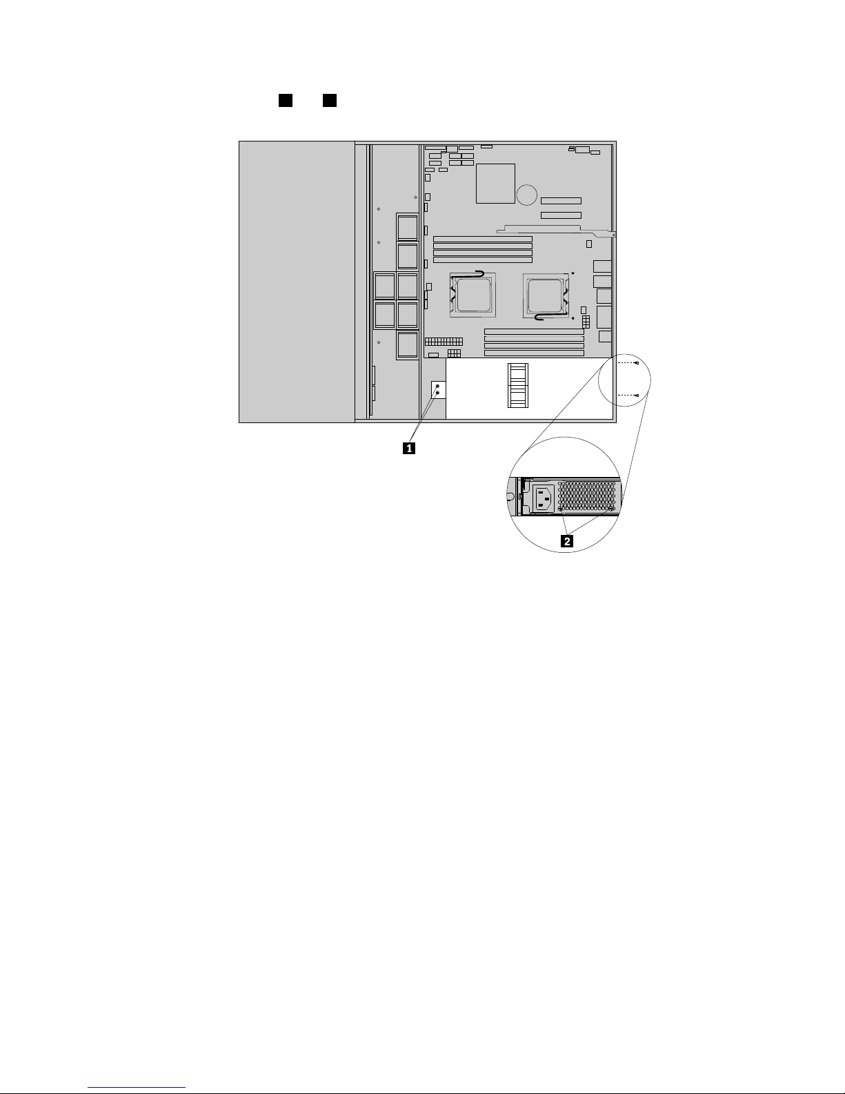
3.Removethefourscrews1and2thatsecurethepowersupply.
Figure45.Removingthescrewsthatsecurethepowersupply
Chapter5.Installing,removing,orreplacinghardware59
Page 72
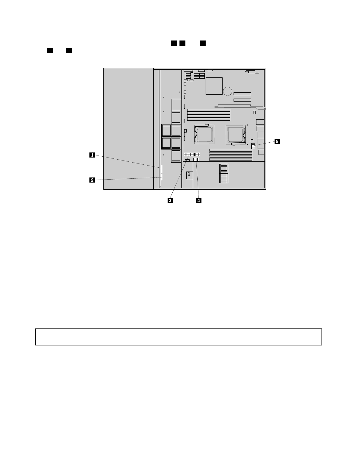
4.Disconnectthepowercablesfromconnectors3,4,and5onthesystemboard,andfromconnectors
1and2onthebackplane.
Figure46.Disconnectingthepowercables
5.Disconnectthepowercablesfromanyothercardsordevices.
Note:Thepowercablesarepartofthepowersupply.Donottrytoremoveordisconnectthepower
cablesfromthepowersupply.
6.Carefullyliftthepowersupplyoutoftheserver.
7.Ifyouareinstructedtoreturnthepowersupply,followallpackaginginstructionsanduseanypackaging
materialsthataresuppliedtoyouforshipping.
Whattodonext:
•Toinstallanewpowersupply,see“Installingthepowersupply”onpage60.
•Toworkwithanotherpieceofhardware,gototheappropriatesection.
Installingthepowersupply
Attention:Donotopenyourserverorattemptanyrepairbeforereadingandunderstandingthe“Safetyinformation”
onpageiii
and“Guidelines”onpage19.
Thissectionprovidesinstructionsonhowtoinstallthepowersupply.
Whenyouinstallapowersupply,observethefollowingprecautions.
60ThinkServerUserGuide
Page 73
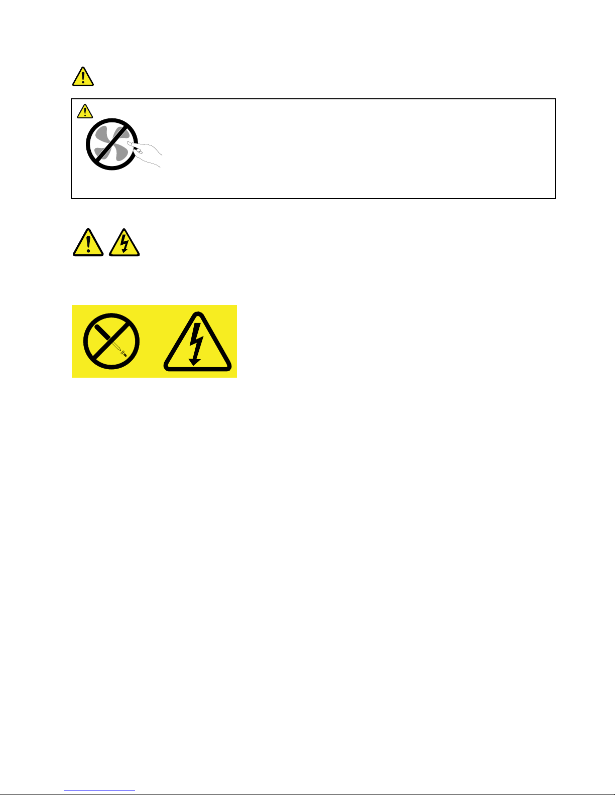
DANGER
Hazardousmovingparts.Keepngersandotherbodypartsaway.
Statement8
CAUTION:
Neverremovethecoveronapowersupplyoranypartthathasthefollowinglabelattached.
Hazardousvoltage,current,andenergylevelsarepresentinsideanycomponentthathasthislabel
attached.Therearenoserviceablepartsinsidethesecomponents.Ifyoususpectaproblemwith
oneoftheseparts,contactaservicetechnician.
Toinstallthepowersupply,dothefollowing:
1.Removeallmediafromthedrivesandturnoffallattacheddevicesandtheserver.Then,disconnectall
powercordsfromelectricaloutletsanddisconnectallcablesthatareconnectedtotheserver.
2.Removetheservercover.See“Removingtheservercover”onpage21.
Chapter5.Installing,removing,orreplacinghardware61
Page 74
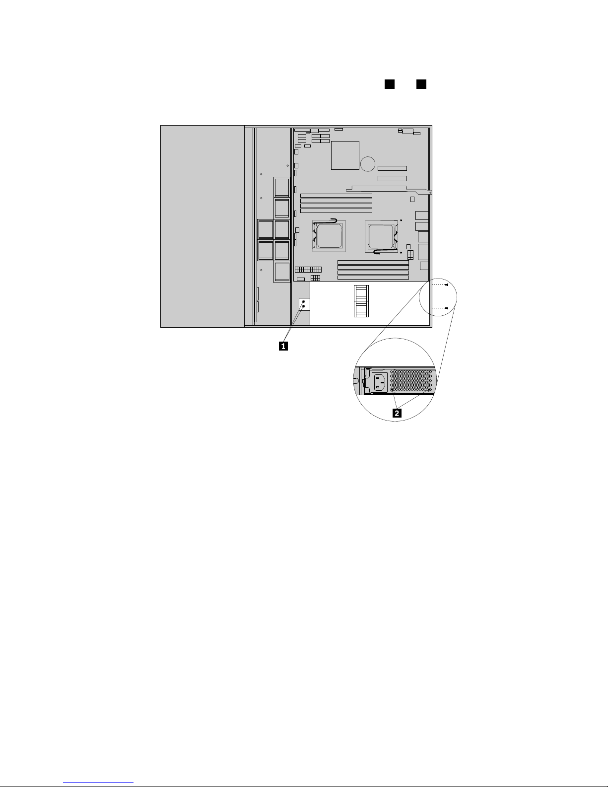
3.Carefullyplacethepowersupplyintotheserverbyaligningthescrewholesinthepowersupplywith
thecorrespondingholesinthechassis.Then,installthefourscrews1and2tosecurethepower
supplyinplace.
Figure47.Installingthescrewstosecurethepowersupply
62ThinkServerUserGuide
Page 75
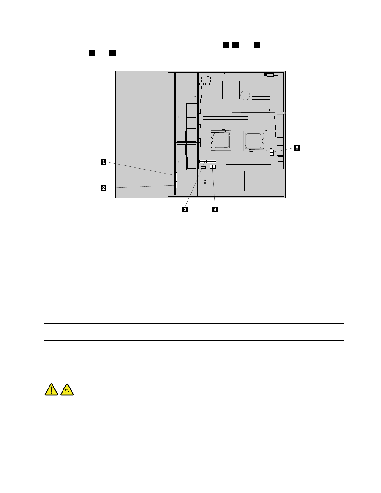
4.Connectthepowercablestothesystemboardconnectors3,4,and5,andtothebackplane
connectors1and2.
Figure48.Connectingthepowercables
5.Connectthepowercablestoanyothercardsordevices.
Whattodonext:
•Toworkwithanotherpieceofhardware,gototheappropriatesection.
•Tocompletetheinstallation,goto“Completingthepartsreplacement”onpage67.
Removingorinstallingthemicroprocessor
Thissectionprovidesinstructionsonhowtoremoveorinstallthemicroprocessor.
Removingthemicroprocessor
Attention:Donotopenyourserverorattemptanyrepairbeforereadingandunderstandingthe“Safetyinformation”
onpageiii
and“Guidelines”onpage19.
Thissectionprovidesinstructionsonhowtoremovethemicroprocessor.
CAUTION:
Theheatsinkandmicroprocessormightbeveryhot.T urnofftheserverandwaitthreetoveminutes
tolettheservercoolbeforeremovingtheservercover.
Toremovethemicroprocessor,dothefollowing:
1.Removeallmediafromthedrivesandturnoffallattacheddevicesandtheserver.Then,disconnectall
powercordsfromelectricaloutletsanddisconnectallcablesthatareconnectedtotheserver.
Chapter5.Installing,removing,orreplacinghardware63
Page 76
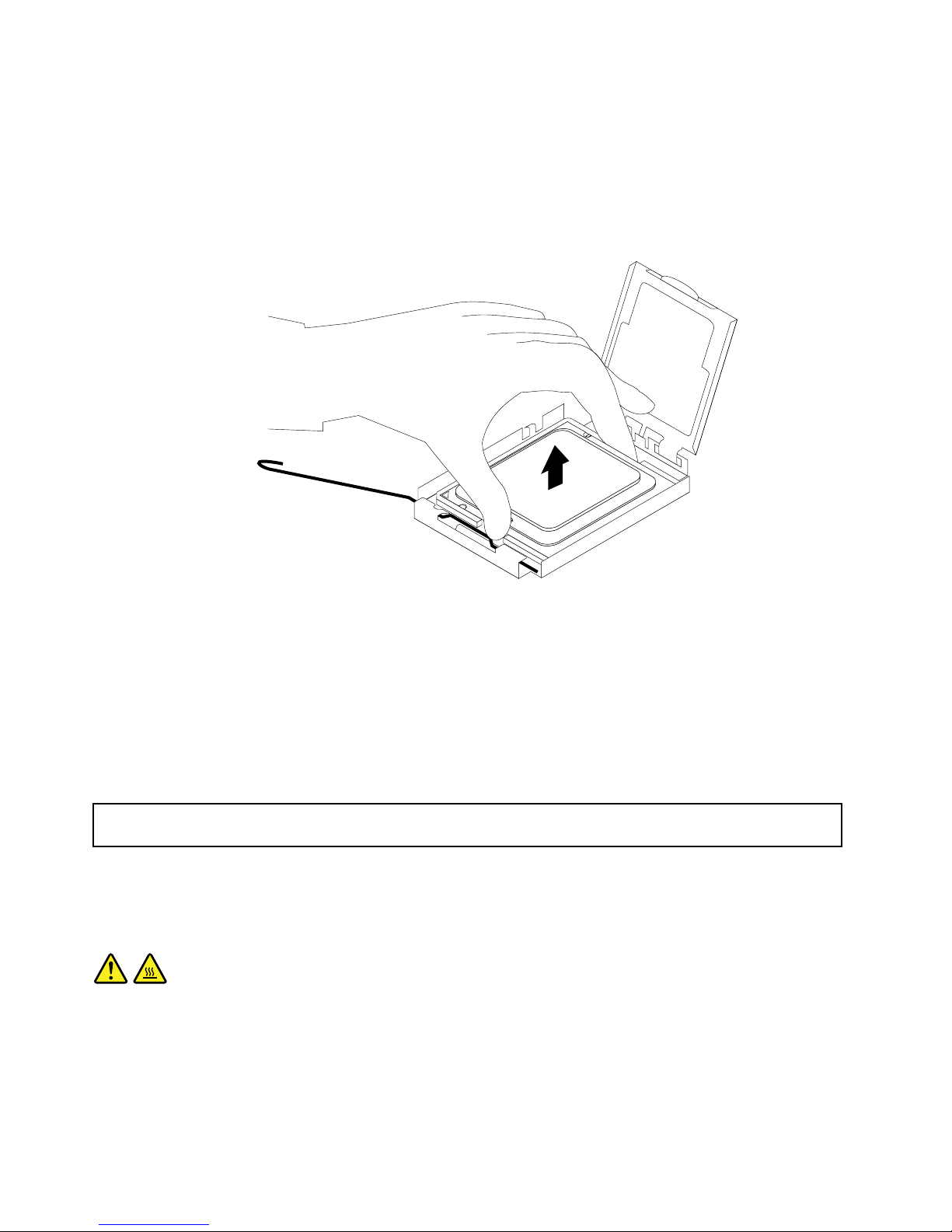
2.Removetheservercover.See“Removingtheservercover”onpage21.
3.Removetheheatsinkassembly.See“Removingtheheatsinkassembly”onpage55.
4.Liftthesmallhandleandopentheretainertoaccessthemicroprocessor.Then,carefullyliftthe
microprocessorstraightupandoutofthesocket,andplaceitonastatic-protectivesurface.
Note:Touchonlytheedgesofthemicroprocessor.
Figure49.Removingthemicroprocessor
5.Ifyouareinstructedtoreturnthemicroprocessor,followallpackaginginstructionsanduseany
packagingmaterialsthataresuppliedtoyouforshipping.
Whattodonext:
•Toworkwithanotherpieceofhardware,gototheappropriatesection.
•Tocompletetheremovalprocedure,goto“Completingthepartsreplacement”onpage67.
Installingthemicroprocessor
Attention:Donotopenyourserverorattemptanyrepairbeforereadingandunderstandingthe“Safetyinformation”
onpageiii
and“Guidelines”onpage19.
Thissectionprovidesinstructionsonhowtoinstallthemicroprocessor.
CAUTION:
Theheatsinkandmicroprocessormightbeveryhot.T urnofftheserverandwaitthreetoveminutes
tolettheservercoolbeforeremovingtheservercover.
Note:Whenyouneedtoinstallasecondmicroprocessor,rstremovethedualheatsinkandthen
removeexcessgreasefromtherstmicroprocessorandthemicroprocessorsocketarea.Makesurethe
microprocessorandsocketareaarecleanofgrease.Usethenewheatsinkthatcomeswiththesecond
64ThinkServerUserGuide
Page 77
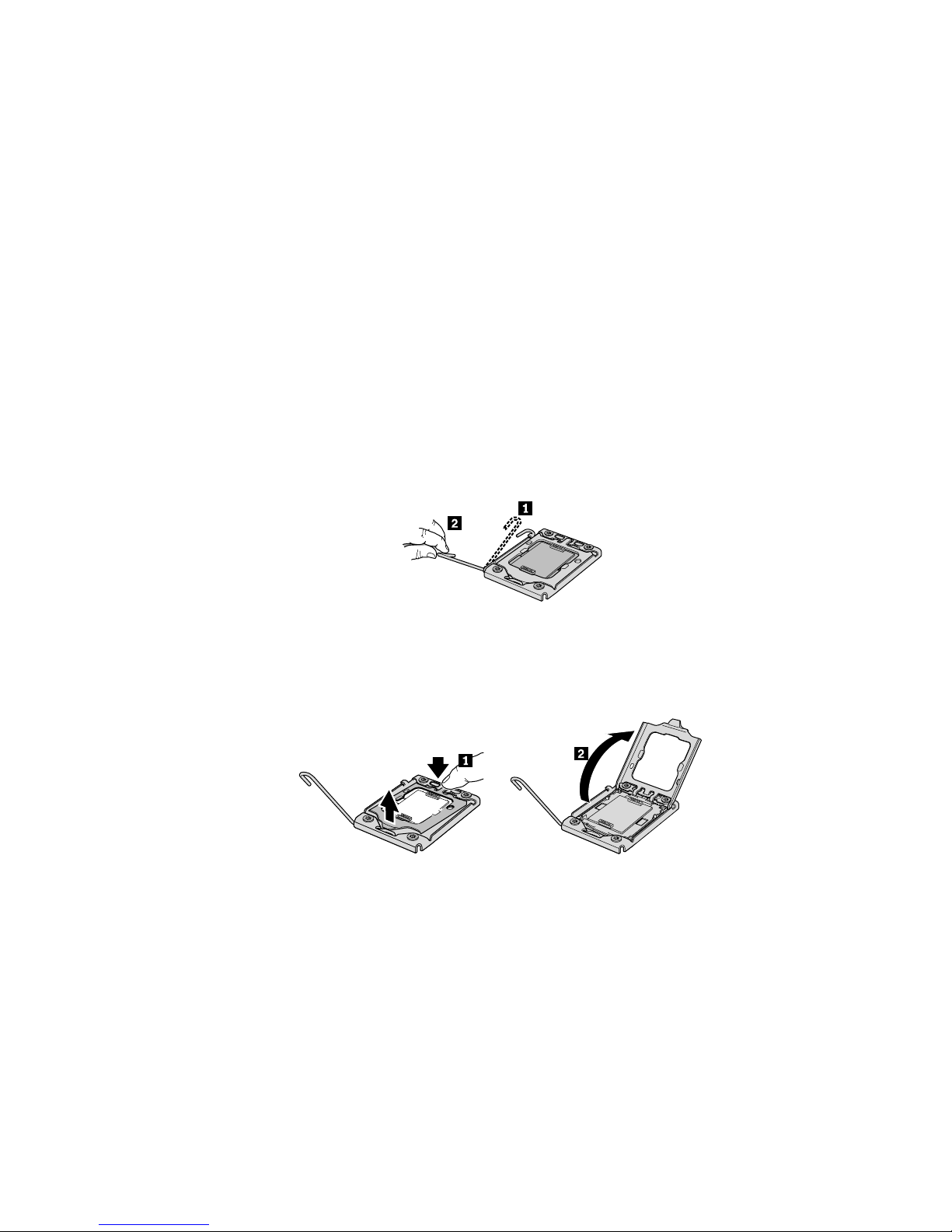
microprocessoroptionkitanddisposeoftheoldone.Thenewheatsinkhasgreasealreadyappliedforboth
therstandsecondmicroprocessors.
Foroptimalperformance,followthesemicroprocessorinstallationrules:
1.Whentwomicroprocessorsareinstalled,bothmusthavethesamecorevoltageandcorespeed.
2.Whenonlyonemicroprocessorisinstalled,itmustbeinthesocketlabeledCPU0.Theothersocket
mustbekeptempty.
3.AlwaysinstallthemicroprocessorrstintotheCPU0socket,andtheninstallanothermicroprocessor
intotheCPU1socketifyouwanttoinstalltwomicroprocessors.
Toinstallthemicroprocessor,dothefollowing:
1.Removeallmediafromthedrivesandturnoffallattacheddevicesandtheserver.Then,disconnectall
powercordsfromelectricaloutletsanddisconnectallcablesthatareconnectedtotheserver.
2.Removetheservercover.See“Removingtheservercover”onpage21.
3.Removetheheatsinkassembly.See“Removingtheheatsinkassembly”onpage55.
4.Pressdownandpushthesmallhandleoutwardonthemicroprocessorsockettoliftthehandleto
theopenposition.
Figure50.Liftingthehandle
5.Gentlypresstheretainerofthemicroprocessorsockettoopenit.
Figure51.Openingtheretainer
Chapter5.Installing,removing,orreplacinghardware65
Page 78
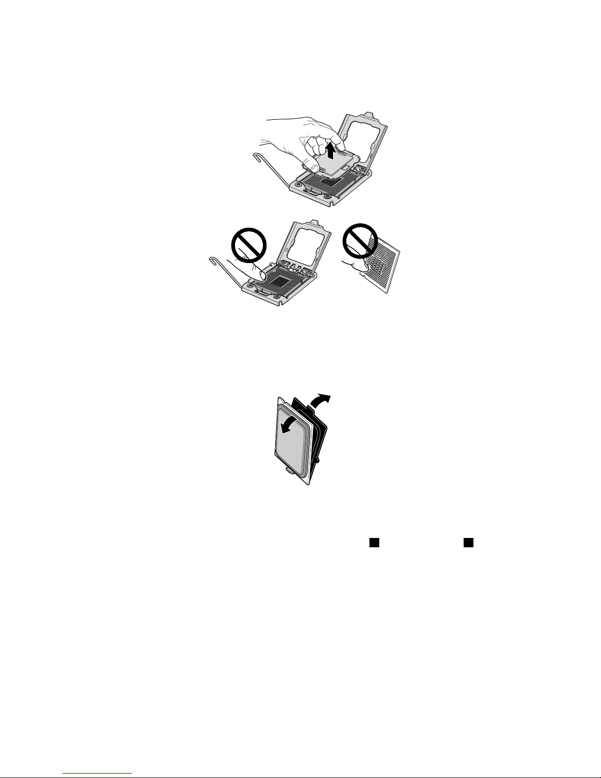
6.Removetheprotectivecoverfromthemicroprocessorsocket.T oavoiddamagingthepinsinthe
microprocessorsocket,donottouchthepinswhileremovingthecover.
Figure52.Removingthemicroprocessorsocketcover
7.Removethenewmicroprocessorfromtheprotectivecoverthatprotectsthegoldcontactsonthe
bottomofthenewmicroprocessor.
Figure53.Removingthenewmicroprocessorfromtheprotectivecover
8.Holdthenewmicroprocessorbytheedgesandalignthenotches1onitwiththetabs2inthe
microprocessorsocket.Then,installthemicroprocessorintothesocket.
66ThinkServerUserGuide
Page 79
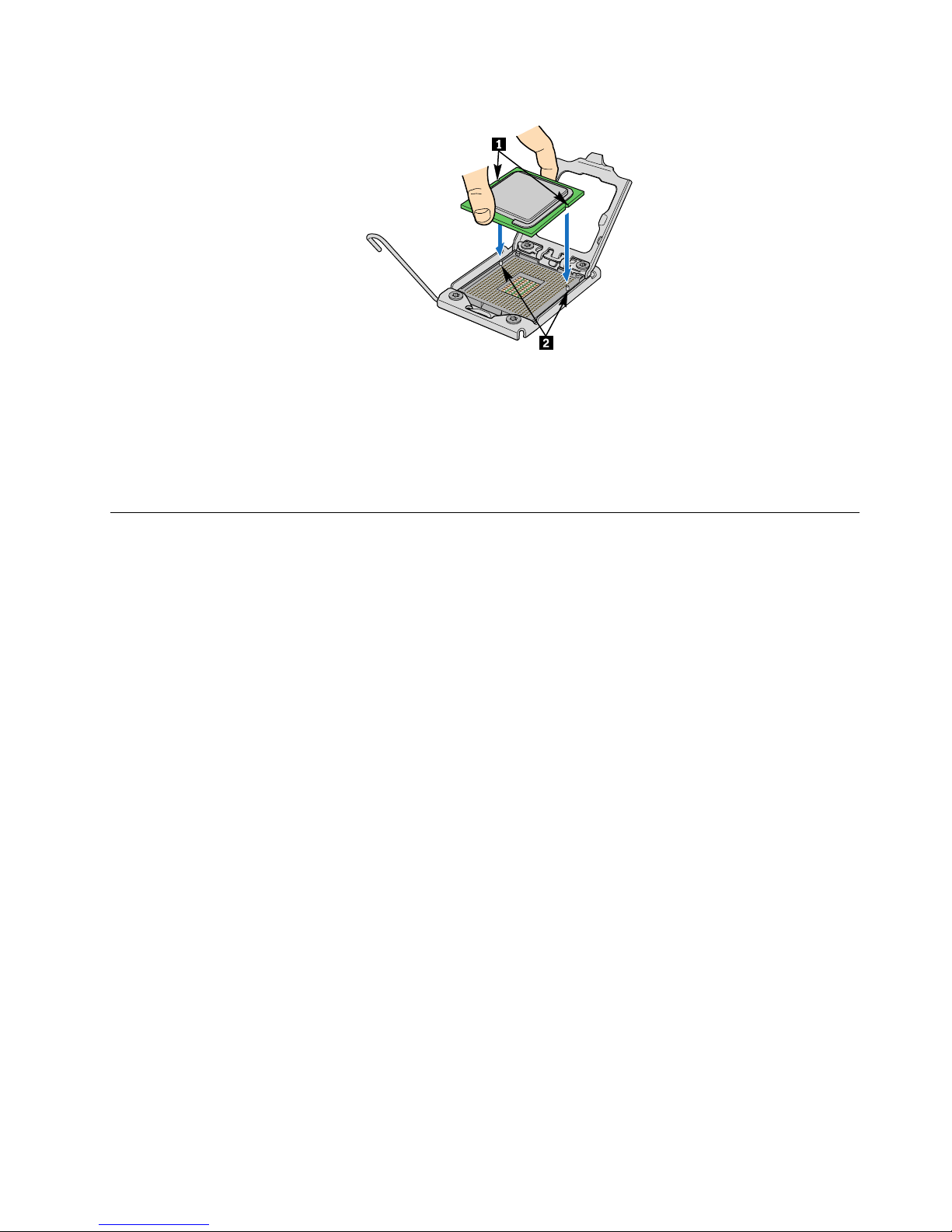
Figure54.Installingthemicroprocessor
Whattodonext:
•Toworkwithanotherpieceofhardware,gototheappropriatesection.
•Tocompletetheinstallation,goto“Completingthepartsreplacement”onpage67.
Completingthepartsreplacement
Thissectionprovidesinstructionstohelpyoucompletethepartsreplacementandturnonyourserver.
Tocompletethepartsreplacement,youmustreinstalltheservercover,reconnectallthecablesand,for
somedevices,runtheSetupUtilityprogramtodofurthersetup.
Installingtheservercover
Thissectionprovidesinstructionsonhowtoinstalltheservercover.
Attention:Forpropercoolingandairow,installtheservercoverbeforeturningontheserver.Operating
theserverforextendedperiodsoftime(morethan30minutes)withthecoverremovedmightdamage
servercomponents.
Toinstalltheservercover,dothefollowing:
1.Makesurethatallcables,add-oncards,andothercomponentsareinstalledandseatedcorrectlyand
thatyouhavenotleftloosetoolsorpartsinsidetheserver.Also,makesurethatallinternalcablesare
correctlyrouted.
2.Positiontheservercoveronthechassissothattherailguidesonthebottomoftheservercoverengage
therails.Then,slidetheservercovertothefrontoftheserveruntilitsnapsintopositionandisclosed.
Then,tightenthethumbscrewtosecuretheservercover.
Note:Althoughtheservercoverissecuredbyathumbscrew,forsafetyconsideration,besuretousea
tool,forexampleascrewdriver,totightenthethumbscrewandalwaysmakesurethatthethumbscrew
issecurelyinstalled.Also,donotover-tightenthethumbscrew.
Connectingthecables
Attention:Topreventdamagetoequipment,connectthepowercordslast.
Iftheservercablesandconnectorpanelhavecolor-codedconnectors,matchthecolorofthecableendwith
thecoloroftheconnector.Forexample,matchabluecableendwithabluepanelconnector,aredcable
Chapter5.Installing,removing,orreplacinghardware67
Page 80

endwitharedconnector,andsoon.See“Rearview”onpage11foranillustrationoftheI/Oconnectorson
therearoftheserver.
Turningontheserver
Whentheserverisconnectedtoanacpowersourcebutisnotturnedon,theoperatingsystemdoesnot
run,andallcorelogicexceptfortheserviceprocessor(theintegratedmanagementmodule)isshutdown;
however,theservercanrespondtorequeststotheserviceprocessor,suchasaremoterequesttoturnon
theserver.Thepower-onLEDashestoindicatethattheserverisconnectedtoanacpowersourcebut
isnotturnedon.
Approximatelyvesecondsaftertheserverisconnectedtoacpower,oneormorefansmightstartrunning
toprovidecoolingwhiletheserverisconnectedtopowerandthepower-onbuttonLEDashesquickly.
Approximatelyonetothreeminutesaftertheserverisconnectedtoacpower,thepower-controlbutton
becomesactive(thepower-onLEDashesslowly),andoneormorefansmightstartrunningtoprovide
coolingwhiletheserverisconnectedtopower.Then,youcanturnontheserverbypressingthepower
buttononthefrontcontrolpanel.See“Frontcontrolpanel”onpage12
.
Updatingtheserverconguration
Whenyouturnontheserverforthersttimeafteryouaddorremoveadevice,youmightreceivea
messagesayingthatthecongurationhasbeenchanged.TheSetupUtilityprogramstartsautomatically
sothatyoucansavethenewcongurationsettings.Formoreinformation,seeChapter6“Conguring
theserver”onpage71
.
Someoptionaldeviceshavedevicedriversthatyoumustinstall.Forinformationaboutinstallingdevice
drivers,seethedocumentationthatcomeswitheachdevice.
Theservercomeswithatleastonemicroprocessor.Ifmorethanonemicroprocessorisinstalled,theserver
canoperateasasymmetricmultiprocessing(SMP)server.Youmighthavetoupgradetheoperatingsystem
tosupportSMP.Formoreinformation,seetheoperating-systemdocumentation.
IftheserverhasanoptionalRAIDcontrollerandyouhaveinstalledorremovedaharddiskdrive,seethe
documentationthatcomeswiththeRAIDcontrollerforinformationaboutreconguringthediskarrays.
Turningofftheserver
Whenyouturnofftheserverandleaveitconnectedtoacpower,theservercanrespondtorequeststo
theserviceprocessor,suchasaremoterequesttoturnontheserver.Whiletheserverremainsconnected
toacpower,oneormorefansmightcontinuetorun.Toremoveallpowerfromtheserver,youmust
disconnectitfromthepowersource.
Someoperatingsystemsrequireanorderlyshutdownbeforeyouturnofftheserver.Seeyour
operating-systemdocumentationforinformationaboutshuttingdowntheoperatingsystem.
Statement5
CAUTION:
Thepowercontrolbuttononthedeviceandthepowerswitchonthepowersupplydonotturnoff
theelectricalcurrentsuppliedtothedevice.Thedevicealsomighthavemorethanonepower
cord.T oremoveallelectricalcurrentfromthedevice,ensurethatallpowercordsaredisconnected
fromthepowersource.
68ThinkServerUserGuide
Page 81

Theservercanbeturnedoffinanyofthefollowingways:
•Youcanturnofftheserverfromtheoperatingsystem,ifyouroperatingsystemsupportsthisfeature.After
anorderlyshutdownoftheoperatingsystem,theserverwillturnoffautomatically.
•Youcanpressthepowerbuttontostartanorderlyshutdownoftheoperatingsystemandturnoffthe
server,ifyouroperatingsystemsupportsthisfeature.
•Iftheoperatingsystemstopsfunctioning,youcanpressandholdthepowerbuttonformorethanfour
secondstoturnofftheserver.
•TheservercanbeturnedoffbytheShutdownonLANfeature.
•Theintegratedmanagementmodule(IMM)canturnofftheserverasanautomaticresponsetoacritical
systemfailure.
Connectingexternaldevices
Ifyouinstallasupportedoptionaladapter,youcanattachexternaldevicestotheserver.
Toattachanexternaldevice,dothefollowing:
Note:Ifyouareattachinganexternaldevice,seethedocumentationthatcomeswiththedevicefor
informationaboutcabling.
1.ReadandunderstandtheSafetyInformationonthedocumentationDVDthatcomeswithyourproduct,
and“Guidelines”onpage19.Toobtainacopyofthepublications,goto:
http://www.lenovo.com/support
2.Turnofftheserverandallattacheddevices.
3.Followtheinstructionsthatcomewiththedevicetoprepareitforinstallationandtoconnectitto
theserver.
Chapter5.Installing,removing,orreplacinghardware69
Page 82

70ThinkServerUserGuide
Page 83

Chapter6.Conguringtheserver
Thefollowingcongurationprogramscomewiththeserver:
•SetupUtilityprogram:TheSetupUtilityprogramispartoftheserverrmware.Y oucanusetheSetup
Utilityprogramtoviewyourserverconguration,changethestartupdevicesequence,setthedate
andtime,andsetpasswords.Forinformationaboutusingthisprogram,see“UsingtheSetupUtility
program”onpage71
.
•Ethernetcontrollerconguration:ForinformationaboutconguringtheEthernetcontroller,see
“ConguringtheGigabitEthernetcontroller”onpage84.
•INTELiMSTSATAsoftwareRAIDCongurationUtilityprogram:UsetheINTELiMSTSATAsoftware
RAIDCongurationUtilityprogramtoconguretheonboardSATAcontrollerwithsoftwareRAID
capabilitiesandthedevicesthatareattachedtoit.Forinformationaboutusingthisprogram,see
“ConguringtheonboardSATAsoftwareRAID”onpage83
.
•ThinkServer8708ELPSASRAID,ThinkServer8708EM2SASRAID,orThinkServerRAID700
CongurationUtilityprogram:UsetheCongurationUtilityprogramtoconguretheThinkServer
8708ELPSASRAID,ThinkServer8708EM2SASRAID,orThinkServerRAID700adapterwithRAID
capabilitiesandthedevicesthatareattachedtoit.Forinformationaboutusingthisprogram,seethe
MegaRAIDSASSoftwareUserGuideonthedocumentationDVDthatcamewithyouserver.
Thefollowingtableliststhedifferentservercongurationsandtheapplicationsthatareavailablefor
conguringandmanagingRAIDarrays.
Table11.ServercongurationsandapplicationsforconguringandmanagingRAIDarrays
Serverconguration
RAIDarrayconguration(before
operatingsystemisinstalled)
RAIDarraymanagement(after
operatingsystemisinstalled)
INTELiMSTSATAsoftwareRAIDINTELiMSTCongurationUtility
program(pressCtrl+Itostart)
INTELRAIDStorageManager
(WebConsole)
ThinkServer8708ELPSASRAID
Adapter
LSIMegaRAIDWebBIOS
CongurationUtility(pressCtrl+Hto
start)
MegaRAIDStorageManager(MSM)
ThinkServer8708EM2RAIDAdapterLSIMegaRAIDWebBIOS
CongurationUtility(pressCtrl+Hto
start)
MegaRAIDStorageManager(MSM)
ThinkServerRAID700AdapterLSIMegaRAIDWebBIOS
CongurationUtility(pressCtrl+Hto
start)
MegaRAIDStorageManager(MSM)
UsingtheSetupUtilityprogram
UsetheSetupUtilityprogramtoperformthefollowingtasks:
•Viewcongurationinformation
•ViewandchangeassignmentsfordevicesandI/Oports
•Setthedateandtime
•Setthestartupcharacteristicsoftheserverandtheorderofstartupdevices
•Setandchangesettingsforadvancedhardwarefeatures
•View,set,andchangesettingsforpower-managementfeatures
•Viewandclearerrorlogs
©CopyrightLenovo2010,2012
71
Page 84
•Resolvecongurationconicts
StartingtheSetupUtilityprogram
TostarttheSetupUtilityprogram,dothefollowing:
1.Approximatelythreeminutesaftertheserverisconnectedtoaworkingelectricaloutlet,thepower
buttonbecomesactive.TurnontheserverandthePOSTrunsautomatically.Y ouwillthenseethelogo
screen.ThePOSTisasetoftestsandproceduresthatareperformedeachtimeyouturnonyourserver.
2.PressDelassoonasyouseethelogoscreen.TheSetupUtilityprogramopens.Ifyouhavesetan
administratorpassword,youmusttypetheadministratorpasswordtoaccessthefullSetupUtility
programmenu.Ifyoudonottypethecorrectadministratorpassword,alimitedSetupUtilityprogram
menuisavailable.
Note:YoucanalsopressTABassoonasyouseethelogoscreentoreviewthePOSTprocessand
information.
3.TheSetupUtilityprogrammenulistsvariousitemsaboutthesystemcongurationsettings.Selectthe
settingstovieworchange.
WhenworkingwiththeSetupUtilityprogram,youmustusethekeyboard.Thekeysusedtoperformvarious
tasksaredisplayedatthebottomofeachscreen.
Note:Usethedefaultsettingforanyitemyouarenotfamiliarwith.Donotchangethevalueofunfamiliar
itemsoritemsthatarenotmentionedinthismanualtoavoidanyunexpectedproblems.Ifyoucannotturn
ontheserverbecauseofincorrectBIOSsettings,refertoandusethejumperstoclearCMOSandrecover
tothefactorydefaultsettings.
IntroductionoftheBIOSitems
ThefollowingtableslistallthemainmenusanditemsintheSetupUtilityprogram.Someitemsmightvary
becauseoftheBIOSupdates.
Notes:
1.Usethedefaultsettingforanyitemyouarenotfamiliarwith.Donotchangethevalueofunfamiliar
itemsoritemsthatarenotmentionedinthismanualtoavoidanyunexpectedproblems.Ifyoucannot
turnontheserverbecauseofincorrectBIOSsettings,usethejumpersonthesystemboardtoclear
CMOSandrecovertothefactorydefaultsettings.
2.AfterupdatingtheBIOS,alltheBIOSsettingsbecomethedefaultsettingsoftheupdatedBIOSversion.
YouneedtocheckandreconguretheBIOSsettingsforyourspecicneeds.
Table12.TheSetupUtilityprogrammainmenu
ItemDescription
Main
SetthebasicBIOSparameters.
Advanced
SettheadvancedBIOSparameters.
PCIPnPSetthePCIparameters.
Boot
Setthebootparameters.
SecuritySetthesecurityparameters.
ChipsetSetthechipset.
Exit
ExittheSetupUtilityprogram.
72ThinkServerUserGuide
Page 85
Table13.ItemsundertheMainmenu
ItemOptionDescription
AMIBIOSViewtheBIOSversionandcreation
dateinformation.
Processor
Viewmicroprocessorinformation.
SystemMemory
Viewmemorycapacityinformation.
SystemTimeHH:MM:SSSetsystemtime.
SystemDateMM/DD/YYYYSetsystemdate.
Table14.ItemsundertheAdvancedmenu
ItemDescription
CPUCongurationEnterthesubmenutoseealltheoptions.SeeSubmenus
undertheCPUConguration.
MassStorageControllerCongurationEnterthesubmenutoseealltheoptions.SeeSubmenus
undertheMassStorageControllerConguration.
SuperIOCongurationEnterthesubmenutoseealltheoptions.SeeSubmenus
undertheSuperIOConguration.
USBCongurationEnterthesubmenutoseealltheoptions.SeeSubmenus
undertheUSBConguration.
HardwareHealthCongurationEnterthesubmenutoseealltheoptions.SeeSubmenus
undertheHardwareHealthConguration.
IPMI2.0CongurationEnterthesubmenutoseealltheoptions.SeeSubmenus
undertheIPMI2.0Conguration.
IntelVT -dCongurationEnterthesubmenutoseealltheoptions.SeeSubmenu
undertheIntelVT -dConguration.
RemoteAccessCongurationEnterthesubmenutoseealltheoptions.SeeSubmenus
undertheRemoteAccessConguration.
SystemInformation
Viewthesysteminformation,includingthemachinetype
andmodel,serialnumber,assettag,andUUID.
Note:DonotchangeanyunfamiliaritemvalueundertheAdvancedmenu.
Table15.SubmenusundertheCPUConguration
ItemOptionDescription
C1ESupportDisabled/[Enabled]EnableordisabletheC1Efunction
ofthemicroprocessor.Thissetting
mightimpactsystemperformance.
HardwarePrefetcher
Disabled/[Enabled]
Enableordisabletheprefetch
functionofthemicroprocessor.
Thissettingmightimpactsystem
performance.
AdjacentCacheLinePrefetchDisabled/[Enabled]
Enableordisabletheadjacentcache
lineprefetch.Thissettingmight
impactsystemperformance.
MPSandACPIMADTorderingLegacyordering/[Modernordering]SelecttheMPSandACPIMADT
orderingmethod.
Chapter6.Conguringtheserver73
Page 86

Table15.SubmenusundertheCPUConguration(continued)
ItemOptionDescription
Intel®VirtualizationT echDisabled/[Enabled]
EnableordisabletheIntel
VirtualizationTech.Thistechnology
canprovideadditionalcapacityfor
hardwarecomputing.Ifyousetthis
featuretoEnabled,youhavetoturn
offtheserveranddisconnectthe
powercordfromelectricaloutlet,and
thenreconnectthepowercordand
turnontheservertomakethisfeature
takeeffect.
Execute-DisableBitCapabilityDisabled/[Enabled]
EnablingtheExecute-DisableBit
Capabilitycanpreventtheexecutive
codeofsomemalicioussoftware
fromusingthedatapage.
Intel®HTT echnology[Enabled]/Disabled
Enableordisablethehyper-thread
technology.(Whetheryourserver
supportsthisfeatureornotis
dependingonthetypeoftheinstalled
microprocessor.)
ActiveProcessorCores[All]/1/2
Enableordisablethemulti-core
processingfunction.
Intel®SpeedStep™techDisabled/[Enabled]EnableordisabletheSpeedStep
technology.
Intel®TurboModetechDisabled/[Enabled]
EnableordisabletheTurboMode
technology.
Intel®C-STATEtechDisabled/[Enabled]EnableordisabletheC-STATE
technology.
C3StateDisabled/[ACPIC2]/ACPIC3SetthemicroprocessorC3state
mode.
C6StateDisabled/[Enabled]EnableordisabletheC6stateofthe
microprocessor.
CStatepackagelimitsetting[Auto]/C1/C3/C6/C7SettheCstatepackagelimit.
C1AutoDemotionDisabled/[Enabled]EnableordisabletheC1State
Demotionofthemicroprocessor.
C3AutoDemotionDisabled/[Enabled]EnableordisabletheC3State
Demotionofthemicroprocessor.
ACPITStateDisabled/[Enabled]
Enableordisablethemicroprocessor
throttlinginACPI.
Notes:
1.Thesettingsin[]arethedefaultsettingsintheSetupUtilityprogram.
2.Theaboveoptionsmightvarydependingonthetypeoftheinstalledmicroprocessor.
74ThinkServerUserGuide
Page 87
Table16.SubmenusundertheMassStorageControllerConguration
ItemOptionDescription
SATACongurationDisabled/[Enabled]EnableordisabletheintegratedSATA
controller.
CongureSATAas[IDE]/RAID
Toselecttheharddiskdrivemode.
IfthisoptionissettoIDE,allthe
SATAconnectorswillbecongured
asstand-aloneSATAconnectors.
Notes:
1.Thesettingsin[]arethedefaultsettingsintheSetupUtilityprogram.
2.TheSA TACongurationitemmightnotapplybecauseyourservercamewithanintegratedSAScontroller.
Table17.SubmenusundertheSuperIOConguration
ItemOptionDescription
SerialPort1AddressDisabled/[3F8/IRQ4]/3E8/IRQ4/
2E8/IRQ3
SelecttheI/Obaseaddressand
interruptforserialport1.
SerialPort2AddressDisabled/[2F8/IRQ3]/3E8/IRQ4/
2E8/IRQ3
SelecttheI/Obaseaddressand
interruptforserialport2.
Note:Thesettingsin[]arethedefaultsettingsintheSetupUtilityprogram.
Table18.SubmenusundertheUSBConguration
ItemOptionDescription
LegacyUSBSupportDisabled/[Enabled]/Auto
Enableordisablethesupporton
legacyUSBdevices.
USB2.0ControllerModeFullSpeed/[HiSpeed]SelecttheUSBspeed.
HotplugUSBFDDSupportDisabled/Enabled/[Auto]
Enableordisablethesupportonthe
hot-swapUSBdiskettedrive.
Note:Thesettingsin[]arethedefaultsettingsintheSetupUtilityprogram.
ForexternalUSBdevices,theUSBMassStorageDeviceCongurationsubmenuisasbelow:
EmulationT ype
[Auto]/Floppy/ForcedFDD/Hard
Disk/CDROM
SelectthetypeoftheUSBdevice.
Table19.SubmenusundertheHardwareHealthConguration
ItemOptionDescription
ItemsandoptionswithBMCconguration:
AutoFanControlDisabled/[Enabled]
IfthisoptionissettoDisabled,the
fanrunsatthefullspeed;ifthisoption
issettoEnabled,thefanspeedis
controlledbythesystemtemperature.
PWMMinimalDutyCycle[60%DutyCycle]/45%DutyCycle
/30%DutyCycle
SelectthePWMMinimalDutyCycle
forthefan:60%-100%,45%-100%,
or30%-100%.
SensorDataRegisterMonitoringReadOnly
Thesensordatainthisoptionisfor
readonly.Thedetecteddataincludes
thetemperature,voltageandfan
speed.
ItemsandoptionswithoutBMCconguration:
Chapter6.Conguringtheserver75
Page 88

Table19.SubmenusundertheHardwareHealthConguration(continued)
ItemOptionDescription
H/WHealthFunctionDisabled/[Enabled]
Enableordisablethehardware
monitorfunction.
AutoFANControlDisabled/[Enabled]
IfthisoptionissettoDisabled,the
fanrunsatthefullspeed;ifthisoption
issettoEnabled,thefanspeedis
controlledbythesystemtemperature.
PWMMinimalDutyCycle[60%DutyCycle]/45%DutyCycle
/30%DutyCycle
SelectthePWMMinimalDutyCycle
forthefan:60%-100%,45%-100%,
or30%-100%.
FanFailureLEDIndication
Disabled/[Enabled]
Enableordisablethefanalarm
function.Ifthisoptionissetto
Enabled,amessageaboutfanfailure
willbedisplayedonthePOSTscreen
whentherotationalspeedofeachfan
islessthan800rpm.
HardwareHealthEventMonitoring
ReadOnly
Thesensordatainthisoptionisfor
readonly.Thedetecteddataincludes
thetemperatureandsystemfan
rotationalspeed.
Note:Thesettingsin[]arethedefaultsettingsintheSetupUtilityprogram.
Table20.SubmenusundertheIPMI2.0Conguration
ItemSub-itemOptionDescription
ViewBMCSystemEvent
Log
Viewthesystemeventlog.
ClearBMCSystemEvent
Log
Deletethesystemevent
log.
SetLANCongurationSettheIPaddresssource,
IPaddress,subnetmask,
andgatewayaddress.
SetPEFCongurationPEFSUPPORTDisabled/[Enabled]
EnableordisablethePEF
support.
BMCWatchDogTimer
Action
[Disabled]/ResetSystem/
PowerDown/PowerCycle
DisableorenabletheOS
baseddongle.Ifenabled,
wheneveranyproblems
arisingfromtheoperation
system,suchasthe
systemhalted,thesystem
managementfeaturewill
takeactionsofReset
System,PowerDown,or
PowerCycleattheprompt
ofthedongleTimer.
BMCAlertLEDandBeep[Off]/OnTurnonorturnofftheBMC
alertLEDandbeep.
FWkey
[0000000]
Note:Thesettingsin[]arethedefaultsettingsintheSetupUtilityprogram.
76ThinkServerUserGuide
Page 89
Table21.SubmenuundertheIntelVT-dConguration
ItemOptionDescription
IntelVT-d
Disabled/[Enabled]
Enableordisablethevirtualization
technologyforI/Odevices.
Note:Thesettingsin[]arethedefaultsettingsintheSetupUtilityprogram.
Table22.SubmenusundertheRemoteAccessConguration
ItemOptionDescription
RemoteAccess
[Disabled]/Enabled
Enableordisabletheserialport
remoteaccess.
Note:Thesettingsin[]arethedefaultsettingsintheSetupUtilityprogram.
Table23.ItemsunderthePCIPnPmenu
ItemOptionDescription
ClearNVRAM[No]/Yes
IfthisoptionissettoY es,thatmeans
tocleartheNVRAMinformationwhen
thesystemstartsup.
BootsGraphicAdapterPriority[Auto]/OnboardVGA
IfthisoptionissettoAuto,the
externalgraphicscardwillbeenabled
rstly.Ifnoexternalgraphicscard,
theintegratedgraphicscontrolleris
automaticallyenabled.Ifthisoption
issettoOnboardVGA,onlythe
integratedgraphicscardisenabled.
LAN1
[Auto]/Enabled/Disabled
TheAutooptionmeansto
automaticallyenabletheintegrated
Ethernetcontroller1.TheEnabled
optionmeanstoenabletheintegrated
Ethernetcontroller1.TheDisabled
optionmeanstodisabletheintegrated
Ethernetcontroller1.
LAN1OP-ROM[Enabled]/Disabled
Enableordisablethewake-upfrom
LAN1.
LAN2
[Auto]/Enabled/Disabled
TheAutooptionmeansto
automaticallyenabletheintegrated
Ethernetcontroller2.TheEnabled
optionmeanstoenabletheintegrated
Ethernetcontroller2.TheDisabled
optionmeanstodisabletheintegrated
Ethernetcontroller2.
LAN2OP-ROM[Enabled]/Disabled
Enableordisablethewake-upfrom
LAN2.
Note:Thesettingsin[]arethedefaultsettingsintheSetupUtilityprogram.
Chapter6.Conguringtheserver77
Page 90
Table24.ItemsundertheBootmenu
ItemSub-itemOptionDescription
QuickBoot[Disabled]/Enabled
Enableordisablethequick
bootfeature.
QuietBoot[Enabled]/Disabled
Enableordisablethe
featuretoshowOEMLogo
duringthePOST.
AddOnROM/Display
Mode
[ForceBIOS]/KeepCurrentSettheAddOnROM
DisplayMode.
BootSettingsConguration
BootupNum-Lock
[Off]/OnSettheNum-LockLED
state.
1stBootDeviceBootdevicenames BootDevicePriority
2ndBootDeviceBootdevicenames
Setthestartupdevice
sequence(supportatmost
vestartupdevices).
HardDiskDrives
1stDrive/2ndDrive...
Basedontheinstalledhard
diskdrives.
CD/DVDDrives
1stDrive...Basedontheinstalled
opticaldrives.
Note:Thesettingsin[]arethedefaultsettingsintheSetupUtilityprogram.
Table25.ItemsundertheSecuritymenu
ItemDescription
ChangeSupervisorPasswordSetorchangethesupervisorpassword.Thepassword
canbeanycombinationofupto6(1to6)alphabeticand
numericcharacters.
ChangeUserPasswordSetorchangetheuserpassword.Thepasswordcan
beanycombinationofupto6(1to6)alphabeticand
numericcharacters.
Note:Thesettingsin[]arethedefaultsettingsintheSetupUtilityprogram.
Table26.ItemsundertheChipsetmenu
ItemSub-itemOptionDescription
QPIFrequency[Auto]/4.800GT/5.866GT
/6.400GT
Standardtransferringrate
oftheQPIbus.
QPIL0sandL1Disabled/[Enabled]EnableordisabletheQPI
L0sandL1.
MemoryFrequency
[Auto]/ForceDDR-800/
ForceDDR-1066/Force
DDR-1333
Setthefrequencyofthe
memorymodule.Make
surethatthemandatory
memoryfrequencysetting
islessthanthemaximum
frequencythatthememory
modulecansupport.
CPUBridgeConguration
MemoryMode
[Independent]/Channel
Mirroring/Lockstep
Setthememorychannel
modetoimprovereliability
orefciency.
78ThinkServerUserGuide
Page 91
Table26.ItemsundertheChipsetmenu(continued)
ItemSub-itemOptionDescription
SouthBridgeCongurationRestoreonACPowerLossPowerOff/PowerOn/
[LastState]
Ifthepowerisrecovered
afteroutage,thesystem
willbeatthestatethatyou
setunderRestoreonAC
PowerLoss.
Note:Thesettingsin[]arethedefaultsettingsintheSetupUtilityprogram.
ExitingtheSetupUtilityprogram
Afteryounishviewingorchangingsettings,pressEsctoreturntotheSetupUtilityprogrammainmenu.
YoumighthavetopressEscseveraltimes.Then,youcandooneofthefollowing:
•IfyouwanttosavethenewsettingsandexittheSetupUtilityprogram,pressF10.Otherwise,your
changeswillnotbesaved.
•Ifyoudonotwanttosavethenewsettings,selectExit➙DiscardChangesandExit.
•Ifyouwanttoreturntothedefaultsettings,pressF9orselectExit➙LoadOptimalDefaults.
Usingpasswords
ByusingtheSetupUtilityprogram,youcansetapasswordtopreventunauthorizedaccesstoyourserver
anddata.Thefollowingoptionsareavailabletohelpyousetasupervisorpasswordorauserpassword:
•ChangeSupervisorPassword
•ChangeUserPassword
Youdonothavetosetapasswordtouseyourserver.However,usingapasswordimprovescomputing
security.Ifyoudecidetosetapassword,readthefollowingsections.
Passwordconsiderations
Apasswordcanbeanycombinationofupto6(1to6)alphabeticandnumericcharacters.Forsecurity
reasons,itisrecommendedtouseastrongpasswordthatcannotbeeasilycompromised.T osetastrong
password,usethefollowingguidelines:
Note:TheSetupUtilityprogrampasswordsarenotcasesensitive.
•Havesixcharactersinlength
•Containatleastonealphabeticcharacterandonenumericcharacter
•Notbeyournameoryourusername
•Notbeacommonwordoracommonname
•Besignicantlydifferentfromyourpreviouspasswords
Setting,changing,ordeletingapassword
Thissectionprovidesinstructionsonhowtoset,change,ordeleteapassword.
Toset,change,ordeleteapassword,dothefollowing:
1.StarttheSetupUtilityprogram.See“StartingtheSetupUtilityprogram”onpage72.
2.FromtheSetupUtilityprogrammainmenu,selectSecurity➙ChangeSupervisorPasswordor
ChangeUserPassword.Forinformationaboutthesupervisorpasswordanduserpassword,see
ItemsundertheSecuritymenu.
3.Followtheinstructionsonthescreentoset,change,ordeleteapassword.
Chapter6.Conguringtheserver79
Page 92

Note:Apasswordcanbeanycombinationofupto6(1to6)alphabeticandnumericcharacters.For
moreinformation,see“Passwordconsiderations”onpage79.
RAIDcontrollers
ThefollowingtableliststhevariousutilitiesavailabletocongureRAIDcontrollersbeforeanoperating
systemisinstalled.
Table27.RAIDutilities
UtilityDescriptionLocation
Wheretondmore
information
EasyStartupRAID
congurationutility
•Forusewithall
factory-supportedRAID
controllers
•Automaticallydetects
hardwareandlists
allsupportedRAID
congurations
•Conguresonedisk
arraypercontroller
usingalldrivescurrently
attachedtothecontroller
•CreatedaRAIDresponse
lethatcanbeused
tocongureRAID
controllersonsimilarly
conguredLenovo
servers.
EasyStartupDVD“UsingtheThinkServer
EasyStartupprogram”on
page80
INTELiMSTSATAsoftware
RAIDCongurationUtility
program
INTELiMSTSATAsoftware
RAID
PressCtrl+Itostart“Conguringtheonboard
SATAsoftwareRAID”on
page83
LSIMegaRAIDWebBIOS
CongurationUtility
ThinkServer8708ELPSAS
RAIDAdapter,ThinkServer
8708EM2RAIDAdapter,
orThinkServerRAID700
Adapter(9260-8i)
PressCtrl+Htostart
RefertotheMegaRAID
SASSoftwareUserGuide
onthedocumentationDVD
thatcamewithyouserver.
Andyoucanndandinstall
theMegaCLIprogramand
theMegaRAIDStorage
Managerprograminthe
ThinkServerEasyStartup
DVDthatcamewithyour
server.InserttheDVDinto
theopticaldriveandthe
lesareinthe\T oolsAnd
Utilitiesdirectory.
UsingtheThinkServerEasyStartupprogram
TheThinkServerEasyStartupDVDsimpliestheprocessofconguringyourRAIDcontrollersandinstalling
anoperatingsystem.TheprogramworksinconjunctionwithyourWindowsorLinuxoperating-system
installationdisctoautomatetheprocessofinstallingtheoperatingsystemsandassociateddevicedrivers.
IfyoudidnotreceiveanThinkServerEasyStartupDVDwithyourserver,youcandownloadanimagefrom
theLenovoSupportWebsiteathttp://www.lenovo.com/support.
80ThinkServerUserGuide
Page 93

TheEasyStartupprogramhasthefollowingfeatures:
•Self-bootingDVD
•Easy-to-use,language-selectableinterface
•Integratedhelpsystem
•Automatichardwaredetection
•RAIDcongurationutility
•Devicedriversprovidedbasedontheservermodelanddetecteddevices
•Selectablepartitionsizeandlesystem
•Supportformultipleoperatingsystems
•Installstheoperatingsystemanddevicedriversinanunattendedmodetosavetime
•CreatesareuseableresponselethatcanbeusedwithsimilarlyconguredLenovoserverstomake
futureinstallationsevenfaster.
BeforeyouusetheEasyStartupDVD
FunctionalityandsupportedoperatingsystemscanvarywithdifferentversionsoftheEasyStartupprogram.
Tolearnmoreabouttheversionyouhave,dothefollowing:
1.InserttheThinkServerEasyStartupDVDandrestarttheserver.
2.AdvancetotheHomescreen.
3.ClickCompatabilitynotes.Thecompatabilitynotesfeatureprovidesdetailedinformationaboutthe
RAIDcontrollers,operatingsystems,andservercongurationssupportedbythatversionofthe
EasyStartupprogram.
4.ClickUserGuide.TheUserGuideprovidesanoverviewofthevariousfunctionsprovidedbythat
versionoftheEasyStartupprogram.
BeforeusingtheEasyStartupprogramtoinstallanoperatingsystem,makesureanyexternalstorage
devicesandberchannelsareconguredcorrectly.
Setupandconguration
WhenyoustarttheThinkServerEasyStartupDVD,youwillbepromptedforthefollowing:
•Selectthelanguageinwhichyouwanttoviewtheprogram.
•Selectthelanguageofthekeyboardyouwillbeusingwiththeprogram.
Note:Thefollowinglanguagekeyboardsaresupported:English,French,German,Spanish,Japanese,
Turkish,Italian,andDutch.Y ourThinkServerEasyStartupDVDmightbeEnglishonly.Inthiscase,the
keyboardlayoutshouldbeEnglish.
Youwillthenseeoneormoreremindersaboutconguringstoragedevices,andthenyouwillbepresented
withtheLenovoLicenseAgreement.Readthelicenseagreementcarefully.Youmustagreewithtermsin
ordertocontinue.
Afteragreeingtothelicenseagreement,youwillbegiventhefollowingchoices:
•Continuetothemainprograminterface
•Useashortcuttoinstallanoperatingsystembasedaresponselethatyoupreviouslycreatedusingthe
EasyStartupprogram
•UseashortcuttocongureRAIDcontrollersbasedonaRAIDresponselethatyoupreviouslycreated
usingtheEasyStartupprogram
Chapter6.Conguringtheserver81
Page 94

Ifyoucontinuetothemainprograminterface,youwillhavethefollowingselectableoptions:
•Compatibilitynotes:ThisselectionprovidesinformationabouttheRAIDcontrollers,operatingsystems,
andservercongurationssupportedbythatversionoftheEasyStartupprogram.
•UserGuide:Thisselectionprovidesinformationaboutthefeaturesprovidedbythatversionofthe
EasyStartupprogram.
•Hardwarelist:ThisselectiondisplaysalistofhardwaredevicesdetectedbytheEasyStartupprogram.
•CongureRAID:ThisselectionenablesyoutoviewthecurrentRAIDcongurationforeachinstalled
RAIDcontrollerandmakechangesifneeded.
•Installoperatingsystem:Thisselectiondisplaysaseriesofchoicesandpromptstocollectinformation
requiredforinstallation,preparestheharddiskforinstallation,andtheninitiatestheinstallationprocess
usingtheuser-providedoperating-systeminstallationCDorDVD.
•About:Thisselectiondisplaysversioninformationandlegalnotices.
ConguringRAID
TheRAIDcongurationfeaturethatispartoftheEasyStartupprogramenablesyoutoviewandchangeRAID
settingsforsupportedRAIDcontrollers.Throughthisfeature,youhavetheabilitytocongureeachinstalled
controller.Theprogramautomaticallydetectsthenumberofdiscscurrentlyattachedtothecontroller,
determinesthepossibleRAIDcongurationsthatcanbecongured,andpromptsyouthroughthesteps
tocongureoneormorediskarrayswithorwithouthot-spareharddiskdrives.Asyoucongureeach
controlleryouwillbegiventheoptiontosavetheRAIDcongurationsettingstoaRAIDresponsele,which
youcanuseonothersimilarlyconguredLenovoservers.Thismethodsatisesmostusers'needs.
Typicaloperatingsysteminstallation
WhenyouselectInstalloperatingsystem,youwillbepromptedforinformationrequiredfortheinstallation.
Thepromptsvarydependingontheoperatingsystemselected.Thissectiondescribesthetasksassociated
withatypicalWindowsoperatingsysteminstallation.Eachtaskmustbecompletedinorderbeforemoving
tothenexttask.
Note:EnsurethatyourRAIDcontrolleriscorrectlyconguredbeforeyouselectanoperatingsystemtoinstall.
•Selectoperatingsystem:Thistaskenablesyoutoselecttheoperatingsystemthatyouwillbeinstalling.
•Selectdisk:Thistaskenablesyoutoselectthediskwhereyouwanttoinstalltheoperatingsystem.
Note:ThediskthatyouselectmustbesetasthebootdiskintheSetupUtilityprogram.
•Partitionsoptions:Thistaskenablesyoutochoosewhetheryouwanttorepartitiontheselecteddrive
oruseanexistingpartition.
•Partitionsettings:Thistaskenablesyoutochoosethelesystemtypeanddenethepartitionsize.
•Installationsettings:Thistaskpromptsyouforuserandsystemsettings,theoperatingsystemproduct
key,andtheadministratorpassword.
•Networksettings:Thistaskpromptsyoufordomainandworkgroupsettings,Ethernetcontrollertype,IP
addresssettings,DNSsettings,andWINSaddresssettings.
•Installapplications:Thistaskenablesyoutoruncustomcommandsorscriptsattheendofthe
installationprocessandinstalltheThinkServerEasyManageprogramtohelpyoumanageyourservers.
•InstallWindowscomponents:ThistaskenablesyoutoinstalloptionalWindowscomponentssuch
asIIS,ASP.NET,andSNMP .
•Conrmsettings:Thistaskenablesyoutoreviewalloftheinformationyouprovided.
•Saveresponsele:ThistaskgivesyoutheoptionofsavingtheinformationonadisketteorUSBdevice
asaresponseleforfutureinstallationsonsimilarlyconguredLenovoservers.
82ThinkServerUserGuide
Page 95

•Startinstallation:Thistaskstartstheactualinstallationprocess.First,thediskispreparedusingthedisk
andpartitioninformationyouspecied.Thenyouarepromptedtoinserttheoperatingsystemdisk,and
theoperatingsystemisinstalledusingtheinformationthatyouspecied.
ConguringtheonboardSA T AsoftwareRAID
ThischapterprovidesinstructionsonhowtoconguretheonboardSATAsoftwareRAIDbyusingthe
INTELiMSTCongurationUtilityprogram.
RAIDinformation
Duringsystemstartup,theSATARAIDBIOSisinitializedandtheBIOSversionoftheRAIDadapter,the
currentRAIDstatus,andthecongurationofthearraywillbedisplayedonthescreen.Thestatusofthe
arraywillbeoneofthefollowing:
1.Normal:ThisstatusindicatesthenormaloperationoftheRAIDarray.
2.Degraded:Thisstatusindicatesthatmorethanoneharddiskdriveisfaultyordisconnectedfrom
mirrorvolumeandyouhavetoreplacethefaultyharddiskdrivesandrecoverthedatathroughthe
Rebuildfunction.
3.Failed:ThisstatusindicatesthattheRAIDarrayisfailedandunabletoberestoredbyrebuilding.Y ou
havetocreatethearrayagain.
4.Rebuild:Thisstatusindicatesthatthearrayisbeingrebuilt.
StartingtheIntelMatrixStorageManagerprogram
TostarttheIntelMatrixStorageManagerprogram,dothefollowing:
1.DuringthePOST,whenyouseethemessage“PressCtrl-ItoenterCongurationUtility...”,pressCtrl+I.
TheIntelMatrixStorageManagerprogrammainmenuopens.
2.FollowtheinstructionsonthescreentoconguretheSATARAID.Whenworkingwiththisprogram,
youmustusethekeyboard.Thekeysusedtoperformvarioustasksaredisplayedatthebottom
ofeachscreen.
ThemainmenuoftheIntelMatrixStorageManagerprogramincludesthefollowingitems:
•CreateRAIDvolumeisforcreatingtheRAIDvolume.
•DeleteRAIDvolumeisfordeletingtheRAIDvolume.
•ResetDiskstoNon-RAIDisforsettingtheharddiskdrivestononRAID.
•RecoveryVolumeOptionsisarecoveryoptionwhentheRAIDmodeisRecovery.
•Exitisforexitingtheprogram.
CreatingtheRAIDvolume
ThissectionprovidesinstructionsonhowtocreatetheRAIDvolumebyusingtheIntelMatrixStorage
Managerprogram.
TocreatetheRAIDvolumebyusingtheIntelMatrixStorageManagerprogram,dothefollowing:
1.SelectCreateRAIDVolumefromtheIntelMatrixStorageManagerprogrammainmenuandpress
Enter.TheCREATEVOLUMEMENUopens.
2.FollowtheinstructionsonthescreentosetthevolumenameandRAIDlevel,selectharddiskdrives,the
stripsize(RAID1cannotbestriped),andthecapacity.
Note:Donotexceedthemaximumcapacity.
Chapter6.Conguringtheserver83
Page 96

3.Whennishallthesettings,pressEnter.Awarningmessagewillbedisplayed.PressYtoconrm
yoursettingsandcreatethevolume.
DeletingtheRAIDvolume
ThissectionprovidesinstructionsonhowtodeletetheRAIDvolumebyusingtheIntelMatrixStorage
Managerprogram.
TodeletetheRAIDvolumebyusingtheIntelMatrixStorageManagerprogram,dothefollowing:
1.SelectDeleteRAIDVolumefromtheIntelMatrixStorageManagerprogrammainmenuandpressEnter.
TheDELETEVOLUMEMENUopens.
2.FollowtheinstructionsonthescreentoselecttheRAIDvolumeandpressDel.
3.PressYwhenpromptedtodeletetheRAIDvolume.
RebuildingtheRAIDvolume
Whenthereisafailingharddiskdriveinthevolume,youneedtoreplacetheharddiskdrive.Then,the
volumewillbeautomaticallyrebuilt.Therebuildingwillbeperformedintheoperationsystem.
ConguringtheGigabitEthernetcontroller
TheEthernetcontrollersareintegratedonthesystemboard.Theyprovidesaninterfaceforconnecting
toa10Mbps,100Mbps,or1Gbpsnetworkandprovidesfull-duplex(FDX)capability,whichenables
simultaneoustransmissionandreceptionofdataonthenetwork.IftheEthernetportsintheserversupports
auto-negotiation,thecontrollersdetectthedata-transferrate(10BASE-T,100BASE-TX,or1000BASE-T)and
duplexmode(full-duplexorhalf-duplex)ofthenetworkandautomaticallyoperatesatthatrateandmode.
Youdonothavetosetanyjumpersorcongurethecontrollers.However,youmustinstalladevicedriverto
enabletheoperatingsystemtoaddressthecontrollers.
Updatingthermware
ThermwareintheserverisperiodicallyupdatedandisavailablefordownloadontheLenovoSupportWeb
site.Gotohttp://www.lenovo.com/supporttocheckforthelatestlevelofrmware,suchastheBIOS
ROMle,BMCFWandRAIDFWles.
Whenyoureplaceadeviceintheserver,youmighthavetoeitherupdatetheserverwiththelatestversionof
thermwarethatisstoredinmemoryonthedeviceorrestorethepre-existingrmwarefromadisketteor
CDimage.
•TheBIOSROMleisstoredinashonthesystemboard.
•TheEthernetrmwareisstoredinEEPROMontheEthernetcontroller.
•TheonboardSATAsoftwareRAIDrmwareisintegratedintotheBIOSROMonthesystemboard.
•TheSASRAIDcardrmwareisstoredinROMontheSASRAIDcard.
TheEthernetrmwareisdownloadableathttp://www.lenovo.com/support.
UsingtheEasyUpdateFirmwareUpdaterprogram
ThinkServerEasyUpdateFirmwareUpdaterisasoftwareapplicationthatenablesyoutomaintainyour
systemrmwareuptodateandhelpsyouavoidunnecessaryoutages.FirmwareUpdaterupdatestheserver
systemandadapterrmware.
84ThinkServerUserGuide
Page 97

Toupdateyoursystem,dothefollowing:
1.Gotohttp://www.lenovo.com/support.
2.ClickDownload&Drivers➙ThinkServerandthenfollowtheinstructionsontheWebpageto
downloadtheISOimagefortheEasyUpdateFirmwareUpdaterprogram.
3.BurntheISOimagetoadisc.
4.Settheopticaldriveastherstbootdeviceandinsertthediscintotheopticaldrive.Theserverwill
proceeddirectlytotheUserInterfaceApplication’sintroductoryscreen.
5.Readthemessagesandinstructionsdisplayedontheintroductoryscreen.Then,clickNexttoproceed
tothelistofrmwareupdatesavailableontheopticalmedia.
6.ClickApplytobegintheupdates(clickCancelifyouwanttoaborttheupdatesandexit).Allupdates
willruntocompletion,witheachupdater’snativeuserinterfacekeptvisibletotheuser.WhentheUser
InterfaceApplicationregainscontrol,youwillseetheresultsscreen.
Beforedistributingthermwareupdatetootherservers,ensurethatyourservercanrestartsuccessfully
withoutencounteringhardwareproblems.
InstallingtheThinkServerEasyManageprogram
ToinstalltheThinkServerEasyManageAgent,youmustalreadyhaveacoreserverrunningtheThinkServer
EasyManageCoreServerprogram.TheThinkServerEasyManageAgentmustbeinstalledfromthatcore
server.RefertotheThinkServerEasyManageCoreServerdocumentationaboutAgentdeploymentfor
instructionsonthevariouswaystodeploytheThinkServerEasyManageAgenttoyournewserver.
Also,theThinkServerEasyStartupprogramprovidesanoptiontoinstalltheThinkServerEasyManageAgent
aspartoftheoperatingsysteminstallationprocess.
Chapter6.Conguringtheserver85
Page 98

86ThinkServerUserGuide
Page 99
Chapter7.Troubleshooting
Thischapterdescribesthediagnostictoolsthatareavailabletohelpyousolveproblemsthatmightoccurin
theserver.
Ifyoucannotdiagnoseandcorrectaproblembyusingtheinformationinthischapter,seeAppendixB
“Gettinginformation,help,andservice”onpage101
formoreinformation.
Troubleshootingtables
Usethetroubleshootingtablestondsolutionstoproblemsthathaveidentiablesymptoms.
Ifyouhavejustaddednewsoftwareoranewoptionaldeviceandtheserverisnotworking,completethe
followingstepsbeforeyouusethetroubleshootingtables:
1.Checktheoperatorinformationpanel.
2.Removethesoftwareordevicethatyoujustadded.
3.Reinstallthenewsoftwareornewdevice.
DVDdriveproblems
•FollowthesuggestedactionsintheorderinwhichtheyarelistedintheActioncolumnuntiltheproblemis
solved.
•SeethepartslistingintheHardwareMaintenanceManualtodeterminewhichcomponentsarecustomer
replaceableunits(CRUs)andwhichcomponentsareeldreplaceableunits(FRUs).
•Ifanactionstepisprecededby“(Trainedservicetechnicianonly),”thatstepmustbeperformedonlyby
atrainedservicetechnician.
SymptomAction
TheDVDdriveisnot
recognized.
1.Makesurethat:
•TheSA TAchanneltowhichtheDVDdriveisattached(primaryorsecondary)
isenabledintheSetupUtilityprogram.
•Allcablesandjumpersareinstalledcorrectly.
•Thesignalcableandconnectorarenotdamagedandtheconnectorpins
arenotbent.
•ThecorrectdevicedriverisinstalledfortheDVDdrive.
2.Reseatthefollowingcomponents:
a.DVDdrive
b.DVDdrivecables
3.Replacethefollowingcomponentsoneatatime,intheordershown,restarting
theservereachtime:
a.DVDdrive
b.DVDdriveandcables
c.(Trainedservicetechnicianonly)Systemboard
ADVDisnotworkingcorrectly.
1.CleantheDVD.
2.ReseattheDVDdrive.
©CopyrightLenovo2010,2012
87
Page 100
SymptomAction
3.ReplacetheDVDdrive.
TheDVDdrivetrayisnot
working.
1.Makesurethattheserveristurnedon.
2.Inserttheendofastraightenedpaperclipintothemanualtray-releaseopening.
3.ReseattheDVDdrive.
4.ReplacetheDVDdrive.
Generalproblems
•FollowthesuggestedactionsintheorderinwhichtheyarelistedintheActioncolumnuntiltheproblemis
solved.
•SeethepartslistingintheHardwareMaintenanceManualtodeterminewhichcomponentsarecustomer
replaceableunits(CRUs)andwhichcomponentsareeldreplaceableunits(FRUs).
•Ifanactionstepisprecededby“(Trainedservicetechnicianonly),”thatstepmustbeperformedonlyby
atrainedservicetechnician.
SymptomAction
Acoverlockisbroken,anLED
isnotworking,orasimilar
problemhasoccurred.
IfthepartisaCRU,replaceit.IfthepartisaFRU,thepartmustbereplacedbya
trainedservicetechnician.
Harddiskdriveproblems
•FollowthesuggestedactionsintheorderinwhichtheyarelistedintheActioncolumnuntiltheproblemis
solved.
•SeethepartslistingintheHardwareMaintenanceManualtodeterminewhichcomponentsarecustomer
replaceableunits(CRUs)andwhichcomponentsareeldreplaceableunits(FRUs).
•Ifanactionstepisprecededby“(Trainedservicetechnicianonly),”thatstepmustbeperformedonlyby
atrainedservicetechnician.
SymptomAction
Notalldrivesarerecognizedby
theharddiskdrivediagnostic
tests.
Removethedrivethatisindicatedbythediagnostictests;then,runtheharddisk
drivediagnostictestsagain.Iftheremainingdrivesarerecognized,replacethe
drivethatyouremovedwithanewone.
Theserverstopsresponding
duringtheharddiskdrive
diagnostictest.
Removetheharddiskdrivethatwasbeingtestedwhentheserverstopped
responding,andrunthediagnostictestagain.Iftheharddiskdrivediagnostictest
runssuccessfully,replacethedrivethatyouremovedwithanewone.
Aharddiskdrivewasnot
detectedwhiletheoperating
systemwasbeingstarted.
Reseatallharddiskdrivesandcables;then,runtheharddiskdrivediagnostic
testsagain.
Intermittentproblems
•FollowthesuggestedactionsintheorderinwhichtheyarelistedintheActioncolumnuntiltheproblemis
solved.
•SeethepartslistingintheHardwareMaintenanceManualtodeterminewhichcomponentsarecustomer
replaceableunits(CRUs)andwhichcomponentsareeldreplaceableunits(FRUs).
•Ifanactionstepisprecededby“(Trainedservicetechnicianonly),”thatstepmustbeperformedonlyby
atrainedservicetechnician.
88ThinkServerUserGuide
 Loading...