

Lenovo ThinkServer 70D1, ThinkServer 70D2, ThinkServer 70D5, ThinkServer 70DR, ThinkServer 70DDS User Manual
...Page 1

ThinkServerRD650
UserGuideandHardwareMaintenance
Manual
MachineTypes:70D0,70D1,70D2,70D3,70D4,70D5,70DR,70DS,
70DT,and70DU
Page 2

Note:Beforeusingtheinformationandtheproductitsupports,besuretoreadandunderstandthefollowing:
•TheReadMeFirstthatcomeswithyourproduct
•“Safetyinformation”onpageiii
•AppendixA“Notices”onpage197
FirstEdition(September2014)
©CopyrightLenovo2014.
LIMITEDANDRESTRICTEDRIGHTSNOTICE:IfdataorsoftwareisdeliveredpursuantaGeneralServicesAdministration
“GSA”contract,use,reproduction,ordisclosureissubjecttorestrictionssetforthinContractNo.GS-35F-05925.
Page 3

Contents
Safetyinformation..........iii
Productsthatarenotassessed.........x
Safetyinspectionguide............x
Groundingrequirements............xi
Chapter1.Generalinformation.....1
Introduction.................1
Serverdocumentation.............2
Chapter2.Serversetuproadmap...5
Chapter3.Productoverview......7
Serverpackage...............7
Features..................7
Specifications...............12
Software.................13
BIOSandTSMupdateutilities.......13
LenovoPartnerPackforMicrosoftSystem
CenterOperationsManagement......13
LenovoThinkServerDeploymentManager..14
LenovoThinkServerDiagnostics......15
LenovoThinkServerEnergyManager....15
LenovoThinkServerPowerPlanner.....15
LenovoThinkServerSystemManager....15
LenovoThinkServerSystemManager
Premium...............15
Locations.................16
Machinetype,model,andserialnumber
label.................16
Frontviewoftheserver.........17
Frontpanel..............23
Rearviewoftheserver.........25
Servercomponents...........28
AnyRAIDadapter,RAIDcard,and
pass-throughboard...........31
Hot-swap-drivebackplane........36
Systemboardcomponents........43
Systemboardjumpers..........47
SystemfanfaultLEDs..........49
Hot-swap-drivestatusLEDs.......50
PowersupplystatusLEDs........51
Connectingcables...........51
Chapter4.Turningonandturningoff
theserver...............53
Turningontheserver............53
Turningofftheserver............53
Chapter5.Configuringtheserver..55
UsingtheSetupUtilityprogram........55
StartingtheSetupUtilityprogram.....55
ViewinginformationintheSetupUtility
program...............55
SetupUtilityprograminterface......55
Settingthesystemdateandtime.....58
Usingpasswords............58
Selectingastartupdevice........59
ConfiguringtheTPMfunction.......60
SettinganEthernetconnectorforsystem
management.............60
ExitingtheSetupUtilityprogram......60
UpdatingorrecoveringtheBIOS......61
ConfiguringRAID..............62
AboutRAID..............62
ConfiguringRAIDusingtheLenovo
ThinkServerDeploymentManagerprogram.64
ConfiguringtheadvancedSATAorSAS
hardwareRAID.............64
Updatingthefirmware............65
Chapter6.Replacinghardware....67
Guidelines................67
Precautions..............67
Handlingstatic-sensitivedevices.....68
Systemreliabilityguidelines........68
Workinginsidetheserverwiththepoweron.69
Removingorextendingtheserverfromtherack
cabinet..................69
Removingtheservercover..........69
Installing,removing,orreplacinghardware...71
Removingandreinstallingtherackhandles.71
Removingandreinstallingthecooling
shroud................72
Installingorreplacingasystemfan.....74
Removingandreinstallingthesystemfan
cage.................77
Installingorremovingamemorymodule...78
Replacingtherisercard.........85
InstallingorremovingaPCIExpresscard:
Ethernetcard,RAIDcard,andothersupported
typesofPCIExpresscards........90
ReplacingtheAnyRAIDadapterorthe
pass-throughboard...........101
Installingorremovingtheflashmodule...103
InstallingorremovingtheLenovoThinkServer
RAID110iupgradekey.........105
©CopyrightLenovo2014
i
Page 4

InstallingorremovingtheLenovoThinkServer
RAID510iupgradekey.........107
Installingorremovingthesecuredigital
module................110
InstallingorremovingtheThinkServerSystem
ManagerPremium...........112
InstallingorremovingtheThinkServerTrusted
PlatformModule............114
InstallingorremovingtheAnyFabric
adapter................116
Installingorreplacingahot-swapredundant
powersupply.............119
Installingorreplacingaheatsink......121
Installingorreplacingthemicroprocessor..123
InstallingorremovingtheThinkServerRAID
SuperCapacitorModule.........132
Installingorreplacingahot-swapdrive...134
Installinga2.5-inchsolid-statedriveintoa
3.5-inch-drivebay...........138
Installingorremovingtherearbackplane/cage
assembly...............141
Replacingthehot-swap-drivebackplane..143
Replacingthefrontpanelboard......152
Installingorremovingtheintrusionswitch..156
Installingorreplacingtheopticaldrive...159
Installingorreplacingthetapedrive....166
Replacingthecoin-cellbattery......172
Forservicetechnicianonly:replacingthe
systemboard.............174
Forservicetechnicianonly:replacingthe
powerdistributionboard.........179
Completingthepartsreplacement.......183
Reinstallingtheservercoverandreconnecting
cables................183
Updatingtheserverconfiguration.....186
Chapter7.Troubleshootingand
diagnostics.............187
Troubleshootingprocedure..........187
ViewingthestatusanddiagnosticLEDs.....187
Viewingthesystemeventlog.........188
Basictroubleshootingtables.........188
LenovoThinkServerDeploymentManager
programproblems...........188
Opticaldriveproblems..........188
Storagedriveproblems.........189
Memorymoduleproblems........190
Keyboard,mouse,andUSBdevice
problems...............191
Chapter8.Gettinginformation,help,
andservice.............193
Informationresources............193
Usingthedocumentation.........193
ThinkServerWebsite..........193
LenovoSupportWebsite.........193
Helpandservice..............194
Beforeyoucall.............194
Callingforservice............194
Usingotherservices..........195
Purchasingadditionalservices......195
AppendixA.Notices.........197
Trademarks................198
Importantnotes..............198
PolyvinylChloride(PVC)cableandcordnotice..198
Recyclinginformation............198
Batteryreturnprogram..........199
Requirementforbatteriescontaining
perchlorate..............199
RecyclinginformationforBrazil......200
Particulatecontamination..........200
ImportantWEEEinformation.........201
RestrictionofHazardousSubstancesDirective
(RoHS)..................201
EuropeanUnionRoHS..........201
GermanOrdinanceforWorkglossstatement...201
Exportclassificationnotice..........201
Electronicemissionnotices..........202
FederalCommunicationsCommission(FCC)
Statement...............202
Eurasiancompliancemark..........203
ENERGYSTARmodelinformation.......204
Index.................205
iiThinkServerRD650UserGuideandHardwareMaintenanceManual
Page 5
Safetyinformation
Note:Beforeusingtheproduct,besuretoreadandunderstandthemultilingualsafetyinstructionsonthe
documentationDVDthatcomeswiththeproduct.
Antesdeusaroproduto,leiaeentendaasinstruçõesdesegurançamultilínguesnoDVDdedocumentação
queoacompanha.
Предидаизползватетозипродукт,задължителнопрочететеивникнетевмногоезичнитеинструкции
забезопасноствDVDдискасдокументация,койтосепредоставяспродукта.
PrijeupotrebeovogproizvodaobaveznopročitajtevišejezičnesigurnosneuputekojesenalazenaDVD-us
dokumentacijomkojidobivateuzproizvod.
PředpoužitímproduktujetřebasipřečístaporozumětbezpečnostnímpokynůmuvedenýmnadiskuDVDs
dokumentací,kterýjedodávánsproduktem.
Førdubrugerproduktet,skaldusørgeforatlæseogforstådesikkerhedsforskrifter,derfindespåflere
sprog,pådendokumentations-dvd,derfølgermedproduktet.
LuetuotteenmukanatoimitetullaDVD-tietolevylläolevatmonikielisetturvaohjeetennentämäntuotteen
käyttöä.
Avantd'utiliserleproduit,veillezàbienlireetcomprendrelesinstructionsdesécuritémultilinguesfigurant
surleDVDdedocumentationfourniavecleproduit.
Πρινχρησιμοποιήσετετοπροϊόν,βεβαιωθείτεότιέχετεδιαβάσεικαικατανοήσειτιςοδηγίεςασφάλειας,οι
οποίεςείναιδιαθέσιμεςσεδιάφορεςγλώσσεςστοDVDτεκμηρίωσηςπουσυνοδεύειτοπροϊόν.
VorVerwendungdesProduktssolltenSieunbedingtdiemehrsprachigenSicherheitsanweisungenaufder
Dokumentations-DVDlesen,dieimLieferumfangdesProduktsenthaltenist.
AtermékhasználataelőttmindenképpenolvassaelésértelmezzeatermékhezkapottdokumentációsDVD
lemezentalálható,többnyelvenelolvashatóbiztonságielőírásokat.
Primadiutilizzareilprodotto,accertarsidileggereecomprendereleinformazionisullasicurezzamultilingue
disponibilisulDVDdidocumentazionefornitoconilprodotto.
製品をご使用になる前に、製品に付属のDocumentationDVDに収録されているマルチリンガルの「安
全に正しくご使用いただくために」を読んで理解してください。
제품을사용하기전에제품과함께제공되는문서DVD의다국어안전지침을주의깊게읽어보십시오.
Voordatuhetproductgebruikt,moetuervoorzorgendatudemeertaligeveiligheidsinstructiesopde
documentatie-dvdvanhetproducthebtgelezenenbegrijpt.
©CopyrightLenovo2014
iii
Page 6

Przedskorzystaniemzproduktunależyzapoznaćsięzwielojęzycznymiinstrukcjamibezpieczeństwa
znajdującymisięnapłycieDVDzdokumentacjądostarczonąwrazzproduktem.
Antesdeutilizaroproduto,leiaatentamenteasinstruçõesdesegurançamultilinguesqueconstamno
DVDdedocumentaçãofornecidocomoproduto.
Înaintedeautilizaprodusul,asiguraţi-văcăaţicititşiînţelesinstrucţiuniledesiguranţăînmaimultelimbide
peDVD-ulcudocumentaţiecareînsoţeşteprodusul.
Førdubrukerproduktet,måduleseogforstådenflerspråkligesikkerhetsinformasjonenpåDVDenmed
dokumentasjonsomfølgermedproduktet.
Преждечемиспользоватьэтотпродукт ,внимательноознакомьтесьсинструкциямипотехнике
безопасностинаразныхязыках,которыеможнонайтинаDVD-дискесдокументациейвкомплектес
продуктом.
在使用本产品之前,请务必先阅读和了解产品附带的文档DVD中的多语言安全说明。
Prenegotoupotrebiteproizvodobaveznopaljivoproitajteiprouiteviejezikouputstvozabezbednostna
dokumentacionomDVD-ukojistedobiliuzproizvod.
PredpouvanmproduktusipretajteviacjazynbezpenostnpokynynadiskuDVDsdokumentcioudodanoms
produktom.
Predenzačneteuporabljatiizdelek,jepomembno,daprebereteinrazumetevečjezičnavarnostnanavodila
naDVD-juzdokumentacijo,kistegaprejeliskupajzizdelkom.
Antesdeutilizarelproducto,asegúresedeleerycomprenderlasinstruccionesdeseguridadmultilingüesdel
DVDdedocumentaciónqueseproporcionaconelproducto.
Varnogamedattläsasäkerhetsinstruktionernapådokumentations-DVD-skivansomföljermedprodukten
innandubörjaranvändaprodukten.
使用本產品之前,請務必閱讀並瞭解產品隨附的文件DVD上的多國語言版本安全資訊。
Buürünükullanmadanönce,ürünlebirliktegönderilenbelgeDVD'siüzerindekiçokdiliçerengüvenlik
yönergeleriniokuyupanladýðýnýzdaneminolun.
Передвикористаннямцьогопродуктууважноознайомтесязінструкціямизтехнікибезпекинарізних
мовах,щоможназнайтинаDVD-дискуздокументацієювкомплектізпродуктом.
Important:Fortranslatedversionsofthecautionordangerstatement,refertotheSafety,Warranty,and
SupportInformationdocument.
Ensurethatyoureadandunderstandallcautionanddangerstatementsinthisdocumentbeforeyouperform
theprocedures.Readandunderstandanyadditionalsafetyinformationthatisincludedwiththeserveror
optionaldevicebeforeyouinstall,remove,orreplacethedevice.
ivThinkServerRD650UserGuideandHardwareMaintenanceManual
Page 7
Statement1
DANGER
Electricalcurrentfrompower,telephone,andcommunicationcablesishazardous.
Toavoidashockhazard:
•Donotconnectordisconnectanycablesorperforminstallation,maintenance,orreconfigurationofthis
productduringanelectricalstorm.
•Connectallpowercordstoaproperlywiredandgroundedelectricaloutlet.
•Ensurethatallpowercordconnectorsaresecurelyandcompletelypluggedintoreceptacles.
•Connecttoproperlywiredoutletsanyequipmentthatwillbeattachedtothisproduct.
•Whenpossible,useonehandonlytoconnectordisconnectsignalcables.
•Neverturnonanyequipmentwhenthereisevidenceoffire,water,orstructuraldamage.
•Disconnecttheattachedpowercords,telecommunicationssystems,networks,andmodemsbeforeyou
openthedevicecovers,unlessinstructedotherwiseintheinstallationandconfigurationprocedures.
•Connectanddisconnectcablesasdescribedinthefollowingtablewheninstalling,moving,oropening
coversonthisproductorattacheddevices.
Toconnect:Todisconnect:
1.TurneverythingOFF.
2.First,attachallcablestodevices.
3.Attachsignalcablestoconnectors.
4.Attachpowercordstooutlets.
5.TurndevicesON.
1.TurneverythingOFF.
2.First,removepowercordsfromoutlets.
3.Removesignalcablesfromconnectors.
4.Removeallcablesfromdevices.
Statement2
DANGER
Dangerofexplosionifbatteryisincorrectlyreplaced.
Whenreplacingthelithiumcoincellbattery,useonlythesameoranequivalenttypethatis
recommendedbythemanufacturer .Thebatterycontainslithiumandcanexplodeifnotproperly
used,handled,ordisposedof.
Donot:
•Throworimmerseintowater
•Heattomorethan100°C(212°F)
•Repairordisassemble
Disposeofthebatteryasrequiredbylocalordinancesorregulations.
©CopyrightLenovo2014
v
Page 8
Statement3
CAUTION:
Whenlaserproducts(suchasCD-ROMs,DVDdrives,fiberopticdevices,ortransmitters)are
installed,notethefollowing:
•Donotremovethecovers.Removingthecoversofthelaserproductcouldresultinexposureto
hazardouslaserradiation.Therearenoserviceablepartsinsidethedevice.
•Useofcontrolsoradjustmentsorperformanceofproceduresotherthanthosespecifiedherein
mightresultinhazardousradiationexposure.
DANGER
SomelaserproductscontainanembeddedClass3AorClass3Blaserdiode.Notethefollowing:
Laserradiationwhenopen.Donotstareintothebeam,donotviewdirectlywithoptical
instruments,andavoiddirectexposuretothebeam.
Statement4
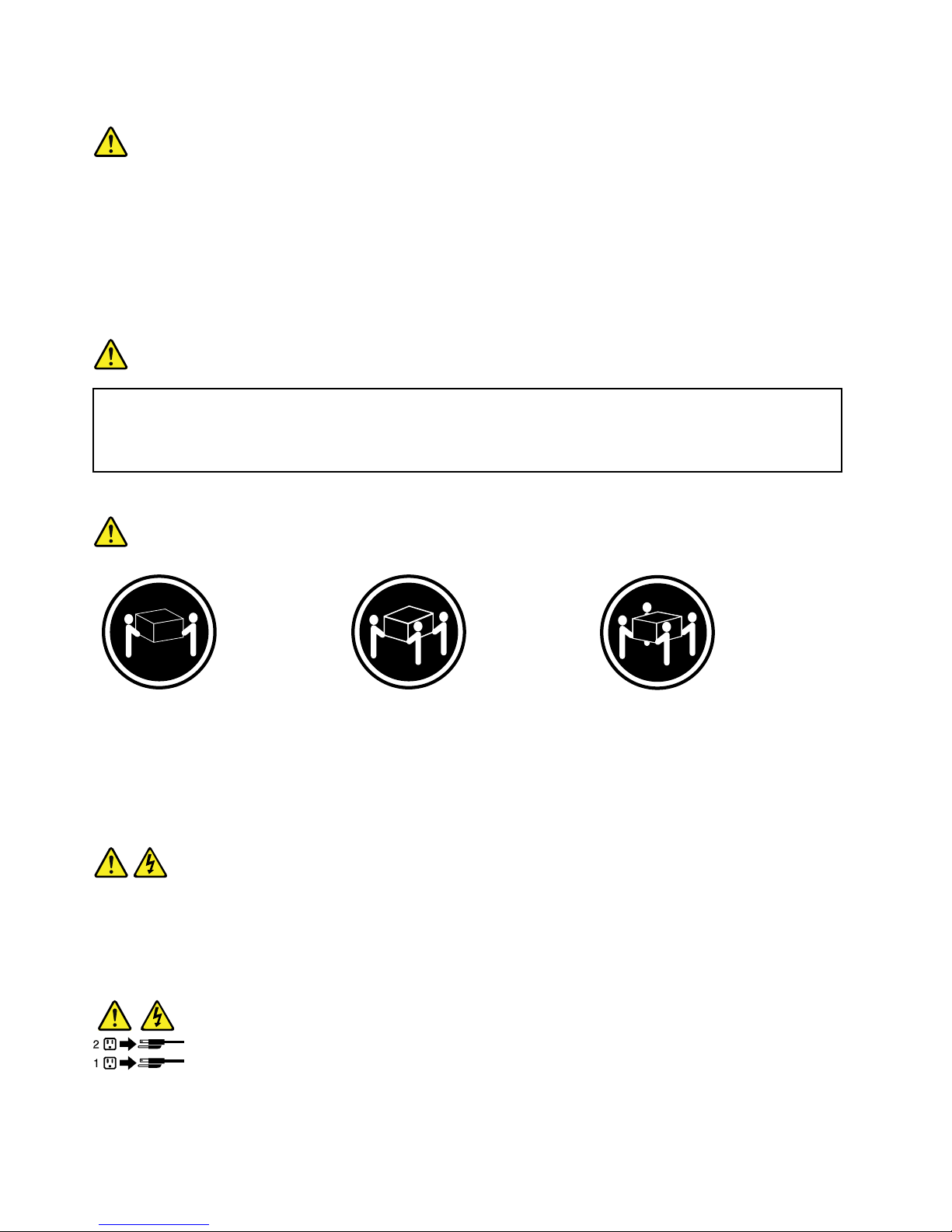
≥18kg(39.7lb)≥32kg(70.5lb)≥55kg(121.2lb)
<32kg(70.5lb)<55kg(121.2lb)<100kg(220.5lb)
CAUTION:
Usesafepracticeswhenlifting.
Statement5
CAUTION:
Thepowercontrolbuttononthedeviceandthepowerswitchonthepowersupplydonotturnoff
theelectricalcurrentsuppliedtothedevice.Thedevicealsomighthavemorethanonepower
cord.T oremoveallelectricalcurrentfromthedevice,ensurethatallpowercordsaredisconnected
fromthepowersource.
viThinkServerRD650UserGuideandHardwareMaintenanceManual
Page 9
Statement6
CAUTION:
Ifyouinstallastrain-reliefbracketoptionovertheendofthepowercordthatisconnectedtothe
device,youmustconnecttheotherendofthepowercordtoapowersourcethatiseasilyaccessible
incaseitneedstobedisconnected.
Statement7
CAUTION:
Ifthedevicehasdoors,ensurethatyouremoveorsecurethedoorsbeforemovingorliftingthe
devicetoprotectagainstpersonalinjury.Thedoorswillnotsupporttheweightofthedevice.
Statement8
CAUTION:
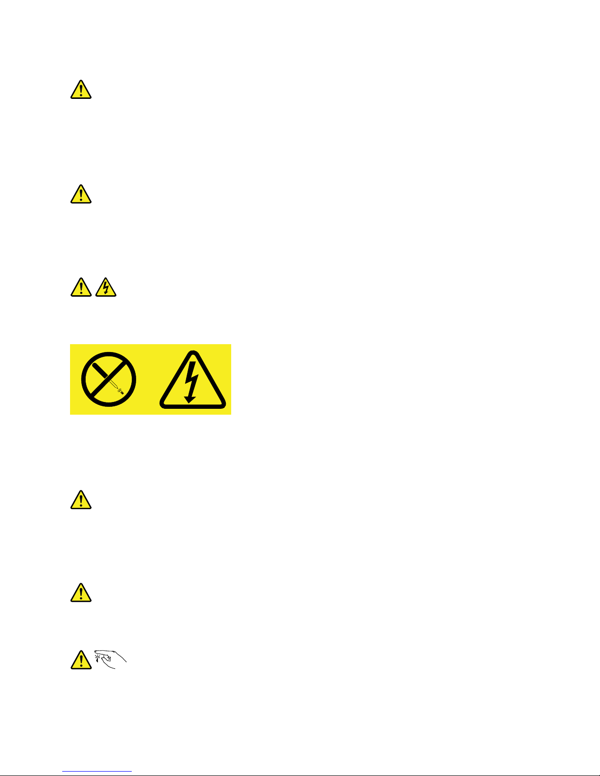
Neverremovethecoveronapowersupplyoranypartthathasthefollowinglabelattached.
Hazardousvoltage,current,andenergylevelsarepresentinsideanycomponentthathasthislabel
attached.Therearenoserviceablepartsinsidethesecomponents.Ifyoususpectaproblemwith
oneoftheseparts,contactaservicetechnician.
Statement9
CAUTION:
Disconnectthehot-swapfancablesbeforeremovingthefanfromthedevicetoprotectagainst
personalinjury.
Statement10
CAUTION:
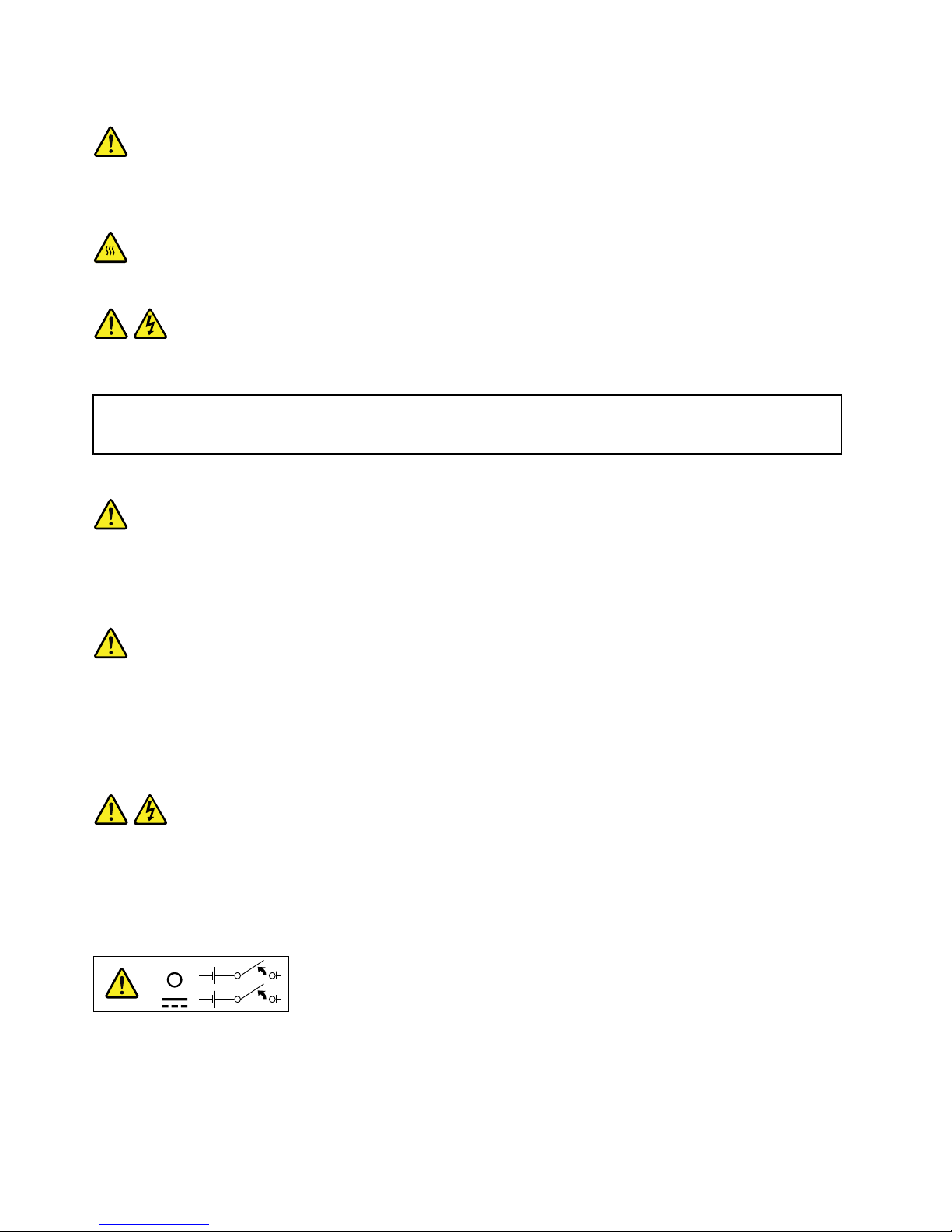
Thefollowinglabelindicatesasharp-edgehazard.
©CopyrightLenovo2014
vii
Page 10
Statement11
CAUTION:
Thefollowinglabelindicatesapotentialheathazard.
Statement12
DANGER
Overloadingabranchcircuitisapotentialfirehazardandashockhazardundercertainconditions.To
avoidthesehazards,ensurethatyoursystemelectricalrequirementsdonotexceedbranchcurrentratings
attheinstallationsite.
Statement13
CAUTION:
Ensurethattherackissecuredproperlytoavoidtippingwhentheserverunitisextendedontherails.
Statement14
CAUTION:
SomeaccessoryoroptionboardoutputsexceedClass2orlimitedpowersourcelimits.You
mustinstalltheappropriateinterconnectingcablinginaccordancewithyourlocalelectricalcode
requirements.
Statement15
CAUTION:
Thepower-controlbuttononthedevicemayputthedeviceinstandbymodeinsteadofturningoff
thedevice.Inaddition,thedevicemighthavemultipleconnectionstodcpower .Toremoveall
electricalcurrentfromthedevice,ensurethatallconnectionstodcpoweraredisconnectedat
thedcpowerinputterminals.
viiiThinkServerRD650UserGuideandHardwareMaintenanceManual
Page 11
Statement16
CAUTION:
Toreducetheriskofelectricshockorenergyhazards:
•Thisequipmentmustbeinstalledbytrainedservicepersonnelinarestricted-accesslocation,as
definedbyyourlocalelectricalcodeandthelatesteditionofIEC60950.
•Connecttheequipmenttoareliablyearthedsafetyextralowvoltage(SELV)source.AnSELV
sourceisasecondarycircuitthatisdesignedsothatnormalandsinglefaultconditionsdonot
causethevoltagestoexceedasafelevel(60Vdirectcurrent).
•Thebranchcircuitovercurrentprotectionmustberatedinaccordancewithlocalelectricalcode
requirements.
•Use1.3mm
2
or16AmericanWireGauge(AWG)copperconductoronly,notexceeding3meters
inlength.
•Torquethewiring-terminalscrewsto1.4newton-metersor12inch-pounds.
•Provideareadilyavailable,approvedandrateddisconnectdeviceinthefieldwiring.
Statement17
CAUTION:
ThisproductcontainsaClass1Mlaser.Donotviewdirectlywithopticalinstruments.
Statement18
CAUTION:
Donotplaceanyobjectontopofrack-mountedproducts.
Statement19
CAUTION:
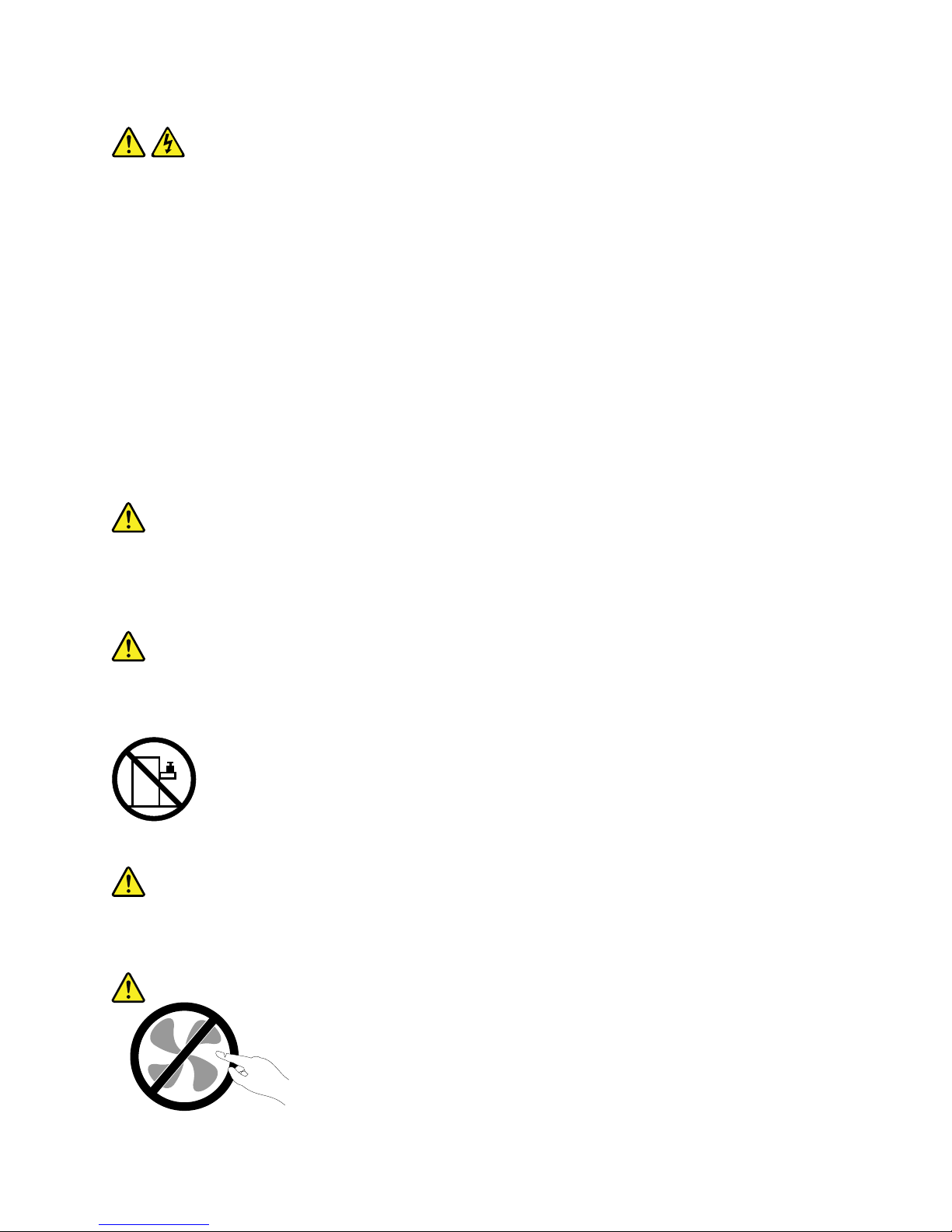
Hazardousmovingparts.Keepfingersandotherbodypartsaway.
©CopyrightLenovo2014
ix
Page 12

Statement20
CAUTION:
Alithiumionbatteryisprovided.T oavoidpossibleexplosion,donotburnthebattery.Replacethe
batteryonlywiththeLenovo-approvedpart.Recycleordiscardthebatteryasinstructedbylocal
regulations.
Productsthatarenotassessed
Typicalproductsthatarenotassessedincludebutnotlimitedtothefollowing:
•ServerandIT-rackcomponents(forexample,uninterruptiblepowersuppliesandcurrentdistribution
systems)
•DevicesinITrooms(forexample,bulkstorageunitsandnetworkproducts)
•Industriallow-voltageswitchgear
Safetyinspectionguide
Thepurposeofthisinspectionguideistoassistyouinidentifyingpotentiallyunsafeconditions.Aseach
machinewasdesignedandbuilt,requiredsafetyitemswereinstalledtoprotectusersandservicetechnicians
frominjury.Thisguideaddressesonlythoseitems.Youshouldusegoodjudgmenttoidentifypotentialsafety
hazardsduetoattachmentofnon-ThinkServerfeaturesoroptionsnotcoveredbythisinspectionguide.
Ifanyunsafeconditionsarepresent,youmustdeterminehowserioustheapparenthazardcouldbeand
whetheryoucancontinuewithoutfirstcorrectingtheproblem.
Considertheseconditionsandthesafetyhazardstheypresent:
•Electricalhazards,especiallyprimarypower(primaryvoltageontheframecancauseseriousorfatal
electricalshock)
•Explosivehazards,suchasadamagedCathodeRayTube(CRT)monitororabulgingcapacitor
•Mechanicalhazards,suchaslooseormissinghardware
Todeterminewhetherthereareanypotentiallyunsafeconditions,usethefollowingchecklistatthebeginning
ofeveryservicetask.Beginthecheckswiththepoweroff,andthepowercordsdisconnected.
Checklist:
1.Checkexteriorcoversfordamage(loose,broken,orsharpedges).
2.Powerofftheserver.Disconnectthepowercords.
3.Checkthepowercordfor:
a.Athird-wiregroundconnectoringoodcondition.Useametertomeasurethird-wireground
continuityfor0.1ohmorlessbetweentheexternalgroundpinandtheframeground.
b.Thepowercordshouldbetheauthorizedtypespecifiedforyourserver.Goto:
http://www.lenovo.com/serviceparts-lookup
c.Insulationmustnotbefrayedorworn.
4.Checkforcrackedorbulgingbatteries.
5.Removethecover.
6.Checkforanyobviousnon-ThinkServeralterations.Usegoodjudgmentastothesafetyofany
non-ThinkServeralterations.
xThinkServerRD650UserGuideandHardwareMaintenanceManual
Page 13

7.Checkinsidetheunitforanyobviousunsafeconditions,suchasmetalfilings,contamination,wateror
otherliquids,orsignsoffireorsmokedamage.
8.Checkforworn,frayed,orpinchedcables.
9.Checkthatthepower-supplycoverfasteners(screwsorrivets)havenotbeenremovedortamperedwith.
Groundingrequirements
Electricalgroundingoftheserverisrequiredforoperatorsafetyandcorrectsystemfunction.Proper
groundingoftheelectricaloutletcanbeverifiedbyacertifiedelectrician.
©CopyrightLenovo2014
xi
Page 14

xiiThinkServerRD650UserGuideandHardwareMaintenanceManual
Page 15

Chapter1.Generalinformation
Thischapterprovidessomegeneralinformationaboutyourproduct.
Thischaptercontainsthefollowingitems:
•“Introduction”onpage1
•“Serverdocumentation”onpage2
Introduction
ThisdocumentforyourLenovo
®
ThinkServer
®
productcontainsinformationabouttheserverfeatures,
specifications,componentlocations,configurationinstructions,hardwarereplacementprocedures,and
basictroubleshootinganddiagnostics.
YourservercomeswithadocumentationDVDthatcontainsvariousserverdocumentstohelpyouuseand
maintaintheserver.Meanwhile,yourservercomeswiththeLenovoThinkServerDeploymentManager
programthatprovidesaconvenientsolutionforconfiguringtheserverandinstallinganoperatingsystem.
TheLenovoLimitedWarranty(LLW)containsthewarrantytermsthatapplytotheproductyoupurchasedfrom
Lenovo.ReadtheLLWonthedocumentationDVDthatcomeswithyourserver.Aprintablegenericversion
ofthelatestLLWalsoisavailableinmorethan30languagesathttp://www.lenovo.com/warranty/llw_02.If
youcannotobtaintheLLWthroughthedocumentationDVDorLenovoWebsite,contactyourlocalLenovo
officeorresellertoobtainaprintedversionoftheLLW,freeofcharge.
Forwarrantyservice,consulttheworldwideLenovoSupporttelephonelist.Telephonenumbersaresubject
tochangewithoutnotice.Themostup-to-datetelephonelistforLenovoSupportisalwaysavailableonthe
Websiteathttp://www.lenovo.com/support/phone.Ifthetelephonenumberforyourcountryorregionisnot
listed,contactyourLenovoresellerorLenovomarketingrepresentative.
Toobtainthemostup-to-dateinformationabouttheserver,goto:
http://www.lenovo.com/thinkserver
LenovomaintainspagesontheWorldWideWeb,whereyoucangetthelatesttechnicalinformationand
downloaddocumentationordevicedriversandupdates.ToaccesstheLenovoSupportWebsite,goto:
http://www.lenovo.com/support
©CopyrightLenovo2014
1
Page 16

Recordinformationaboutyourserverinthefollowingtable.Y ouwillneedtheinformationifyoueverneed
tohaveyourserverserviced.
Forwheretofindtheproductinformationlabelonthechassis,see“Machinetype,model,andserialnumber
label”onpage16
.
Productname
______________________________________________
Machinetypeandmodel(MT-M)
______________________________________________
Serialnumber(S/N)
______________________________________________
Dateofpurchase
______________________________________________
YoucanregisteryourserverwithLenovobyfollowingtheinstructionsat:
http://www.lenovo.com/register
Whenyouregisteryourserver,informationisenteredintoadatabase,whichenablesLenovotocontact
youincaseofarecallorothersevereproblem.AfteryouregisteryourserverwithLenovo,youwillreceive
quickerservicewhenyoucallLenovoforhelp.Inaddition,somelocationsofferextendedprivilegesand
servicestoregisteredusers.
Serverdocumentation
Thistopicprovidesageneraldescriptionofeachdocumentforyourserverandinstructionsonhow
toobtainallthedocuments.
Printeddocuments
Thefollowingdocumentsareprintedoutandincludedinyourserverpackage.
•ReadMeFirst
Thisisamultilingualdocumentyoushouldreadfirst.Thisdocumentguidesyoutoreadthecomplete
warranty,support,andsafetyinformationonthedocumentationDVDthatcomeswithyourserverbefore
usingtheproduct.Thisdocumentalsoprovidesinformationabouthowtofindthemostup-to-date
informationontheLenovoSupportWebsite.
•RackInstallationInstructions
Thisdocumentprovidesinstructionsonhowtoinstallyourserverintoastandardrackcabinetbyusing
therailkitshippedwiththeserver.
Note:AprintedEnglishversionofthisdocumentisincludedinyourserverpackage.PDFversionsof
otherlanguagesareprovidedonthedocumentationDVDthatcomeswiththeserver.
2ThinkServerRD650UserGuideandHardwareMaintenanceManual
Page 17

DocumentationDVD
ThedocumentationDVD,whichcomeswithyourserver,containsvariousdocumentsforyourserverin
PortableDocumentFormat(PDF)andHyperTextMarkupLanguage(HTML).ThedocumentationDVDisnot
bootable.T oviewthedocumentsontheDVD,youwillneedacomputerwithaWebbrowserandtheAdobe
Readerprogram,whichisavailablefordownloadat:
http://www.adobe.com
TostartthedocumentationDVD,inserttheDVDintotheopticaldrive.TheDVDisAutoPlayenabledand
startsautomaticallyinmostMicrosoft
®
Windows
®
environments.IftheDVDfailstostartorifyouareusinga
Linux
®
operatingsystem,openthelaunch.htmfilelocatedintherootdirectoryoftheDVD.
Note:LenovomaintainspagesontheWorldWideWeb,whereyoucangetthelatesttechnicalinformation
anddownloaddocumentationordevicedriversandupdates.Someinformationinthedocumentsonthe
documentationDVDmightchangewithoutnoticeafterthefirstreleaseoftheDVD.Y oucanalwaysobtainall
themostup-to-datedocumentationforyourserverfromtheLenovoWebsiteat:
http://www.lenovo.com/UserManuals
ThefollowingdocumentsareonthedocumentationDVDthatcomeswithyourserver:
•Safety,Warranty,andSupportInformation
Thisisamultilingualdocumentthatincludesallthesafetystatementsforyourproductinmorethan30
languages.Besuretoreadandunderstandallthesafetystatementsbeforeusingtheproduct.This
documentalsoincludestheLenovowarrantystatement,CustomerReplaceableUnits(CRUs)information,
andinformationabouthowtocontacttheLenovoCustomerSupportCenter.
•LenovoLicenseAgreement
ThisdocumentincludesthetermsandconditionsoftheLenovoLicenseAgreement.
•UserGuideandHardwareMaintenanceManual
Thisdocumentprovidesdetailedinformationtohelpyougetfamiliarwithyourserverandhelpyouuse,
configure,andmaintainyourserver.
•RackInstallationInstructions
Thisdocumentprovidesinstructionsonhowtoinstallyourserverintoastandardrackcabinetbyusing
therailkitshippedwiththeserver.
•ThinkServerSystemManagerUserGuide
Thisdocumentprovidesinformationaboutserverremotemanagement.ThisdocumentisinEnglishonly.
YoumightfindthisdocumentonthedocumentationDVDthatcomeswithyourserver.Ifnot,downloadit
fromtheLenovoWebsiteat:
http://www.lenovo.com/UserManuals
Note:Toobtainadvancedremotemanagementfunctions,installaThinkServerSystemManagerPremium
(TSMPremium)ontheTSMPremiumconnectoronthesystemboard.See“Installingorremovingthe
ThinkServerSystemManagerPremium”onpage112
.
•MegaRAIDSASSoftwareUserGuide
ThisdocumentprovidesinformationaboutRedundantArrayofIndependentDisks(RAID)andhowto
usetheutilityprogramstoconfigure,monitor,andmaintainyourserverRAIDandrelateddevices.This
documentisinEnglishonly.
•Otherdocuments
YoumightfindotherdocumentsfortheHostBusAdapter(HBA),Ethernetcard,orotheroptionalparts
onthedocumentationDVD.
Chapter1.Generalinformation3
Page 18

4ThinkServerRD650UserGuideandHardwareMaintenanceManual
Page 19

Chapter2.Serversetuproadmap
Thischapterprovidesageneralroadmaptoguideyouthroughsettingupyourserver.
Theserversetupprocedurevariesdependingontheconfigurationoftheserverwhenitwasdelivered.In
somecases,theserverisfullyconfiguredandyoujustneedtoconnecttheservertothenetworkandanac
powersource,andthenyoucanturnontheserver.Inothercases,theserverneedstohavehardwaredevices
installed,requireshardwareandfirmwareconfiguration,andrequiresanoperatingsystemtobeinstalled.
Thegeneralprocedureforsettingupyourserveris:
1.Unpacktheserverpackage.See“Serverpackage”onpage7.
2.Installanyrequiredhardwareorserveroptions.SeetherelatedtopicsinChapter6“Replacing
hardware”onpage67.
3.Ifnecessary,installtheserverintoastandardrackcabinetbyusingtherailkitshippedwiththeserver.
SeetheRackInstallationInstructionsthatcomeswiththeserver.
4.ConnecttheEthernetcablesandpowercordstotheserver.See“Rearviewoftheserver”onpage
25tolocatetheconnectors.
5.Turnontheservertoverifyoperation.See“Turningontheserver”onpage53.
6.ReviewtheBasicInputOutputSystem(BIOS)settingsandcustomizeasneeded.See“UsingtheSetup
Utilityprogram”onpage55.
7.ConfigureRAIDandinstalltheoperatingsystemanddevicedrivers.See“LenovoThinkServer
DeploymentManager”onpage14and“ConfiguringRAID”onpage62.
8.Installanyadditionaldriversrequiredforaddedfeatures.Refertotheinstructionsthatcomewith
thehardwareoption.
9.ConfigureEthernetsettingsintheoperatingsystembyreferringtotheoperatingsystemhelp.This
stepisnotrequirediftheoperatingsystemwasinstalledusingtheLenovoThinkServerDeployment
Managerprogram.
10.Checkforfirmwareupdates.See“Updatingthefirmware”onpage65.
11.Installmanagementapplicationsandanyotherapplications.Refertothedocumentationthatcomes
withtheapplicationsthatyouwanttoinstall.
©CopyrightLenovo2014
5
Page 20

6ThinkServerRD650UserGuideandHardwareMaintenanceManual
Page 21

Chapter3.Productoverview
Thischapterprovidesinformationabouttheserverpackage,features,specifications,softwareprograms,
andcomponentlocations.
Thischaptercontainsthefollowingitems:
•“Serverpackage”onpage7
•“Features”onpage7
•“Specifications”onpage12
•“Software”onpage13
•“Locations”onpage16
Serverpackage
Theserverpackageincludesthefollowingitems:
•Server
•Railkit(availableonsomemodels)
•Cablemanagementarmorcablemanagementbar(availableonsomemodels)
•Slimopticaldrive(availableonsomemodels)
•Materialbox,includingitemssuchaspowercords,printeddocumentation,andadocumentationDVD
Features
Thistopicprovidesgeneralinformationabouttheserverfeaturesforavarietyofmodels.Dependingonyour
specificmodel,somefeaturesmightvaryorunavailable.Forinformationaboutyourspecificmodel,usethe
SetupUtilityprogram.See“ViewinginformationintheSetupUtilityprogram”onpage55
.Youalsocanrefer
totheProductSpecificationsReferencedocumentforThinkServerproductsat:
http://www.lenovo.com/psref/
Microprocessor
OneortwoIntel
®
Xeon
®
microprocessors(internalcachesizevariesbymodel)
ForalistoftheThinkServermicroprocessoroptions,goto:
http://lenovoquickpick.com/usa/home/thinkserver/rack-and-tower-server
Memory
Yourserverhas24memoryslots.Formoreinformation,see“Memorymoduleinstallationrules”onpage79.
©CopyrightLenovo2014
7
Page 22
Powersupply
•Oneortwo550-watthot-swapredundantpowersupplies(Universalinputandcompliantwith80PLUS
Platinum)
•Oneortwo750-watthot-swapredundantpowersupplies(Universalinputandcompliantwith80PLUS
Platinum)
•Oneortwo750-watthot-swapredundantpowersupplies(Highlineinputandcompliantwith80PLUS
Titanium)
•Oneortwo1100-watthot-swapredundantpowersupplies(Universalinputandcompliantwith80
PLUSPlatinum)
•Oneortwo1600-watthot-swapredundantpowersupplies(Highlineinputandcompliantwith80
PLUSPlatinum)
Note:Whenthe1600-wattpowersupplyworkswithlowlineinput,theoutputpowerchangesto1100
watt.
Systemfans
Yourserversupportsuptosixhot-swapsystemfans.Thisdesignhelpsyouavoidsignificantcooling
problemswhenasystemfanfails.Youcanreplaceasystemfanwithoutturningofftheserver.Tolocatethe
systemfans,see“Systemboardcomponents”onpage43
.
•Ifyourserverisinstalledwithonemicroprocessor,foursystemfans(fan1tofan4)areadequateto
providepropercooling.However,youmustkeepthelocationsforfan5andfan6occupiedbydummy
fanstoensureproperairflow.
•Ifyourserverisinstalledwithtwomicroprocessors,ensurethatallthesixsystemfansareinstalledto
avoidcoolingproblems.
Internaldrives
Internaldrivesaredevicesthatyourserverusestoreadandstoredata.Theinternaldrivessupported
byyourservervarybymodel.
•Internalstoragedrive
–Inthefront:
Yourserversupportsoneofthefollowingstoragedriveconfigurations:
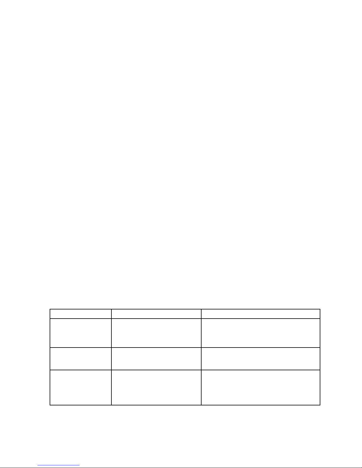
DrivebaysizeDrivebayquantityDrivetype
3.5-inch12
Hot-swap,SA TAorSAS
3.5-inchharddiskdriveor2.5-inchsolid-state
drive
2.5-inch24
Hot-swap,SA TAorSAS
Harddiskdriveorsolid-statedrive
2.5-inch/3.5-inch
mixed
6(2.5-inch)
9(3.5-inch)
Hot-swap,SA TAorSAS
Harddiskdrive(3.5-inch)
Harddiskdriveorsolid-statedrive(2.5-inch)
Note:Y oucaninstalla2.5-inchsolid-statedriveintoa3.5-inch-drivebay.Formoreinformation,see
“Installinga2.5-inchsolid-statedriveintoa3.5-inch-drivebay”onpage138.
8ThinkServerRD650UserGuideandHardwareMaintenanceManual
Page 23
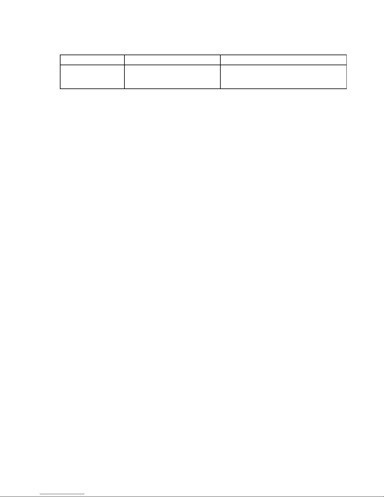
–Intherear:
DrivebaysizeDrivebayquantityDrivetype
2.5-inch2
Hot-swap,SATA
Harddiskdriveorsolid-statedrive
Notes:
–SATAistheacronymforSerialAdvancedTechnologyAttachment.
–SASstandsforSerialAttachedSCSI(SCSIistheacronymforSmallComputerSystemInterface).
–YoucaninstallSATAharddiskdrives,SASharddiskdrives,andsolid-statedrivesintothesameserver.
Thefollowingservermodelsalsoareavailable:
–Servermodelswithoutharddiskdrivesorsolid-statedrives
–Servermodelswithoutharddiskdrives,solid-statedrives,backplanes,AnyRAIDadapters,andrelated
cables
•Opticaldrive
–OneslimSATAopticaldriveinsomemodels
•Tapedrive
–Oneinternaltapedriveinsomemodels
Expansionslots
•Tworisercardassemblyslotsonthesystemboard
•ThreePCIExpress(PCIe)slotsonsystemboard
•ThreeortwoPCIeslotsontherisercard
•OneAnyFabricslotintherearoftheserver
Fordetailedinformation,see“Rearviewoftheserver”onpage25
.
Input/Output(I/O)features
•Ontherearpanel:
–OneDisplayPort®connector
–OneRJ-45Ethernetconnector
–Oneserialconnector
–TwoUSB3.0connectors
•Onthefrontpanel(availableonsomemodels):
–OneDisplayPortconnector
–TwoUSB2.0connectors
Notes:
•IfyourserverhastwoDisplayPortconnectors,theycannotbeenabledatthesametime.
•Ifyouuseavideographicsarray(VGA)monitor,itisrecommendedthatyoupurchaseacompatible
DisplayPorttoVGAadapterfromLenovo.
Tolocatetheconnectors,refertotherelatedtopicsin“Locations”onpage16
.
Chapter3.Productoverview9
Page 24

Videosubsystem
AnintegratedgraphicscontrollerintheThinkServerSystemManagerPremium(TSMPremium),whichalsois
knownastheBaseboardManagementController(BMC)chip,onthesystemboardtosupportDisplayPort
connectorsforconnectingvideodevices
•Integratedgraphicscontroller:On-boardASPEEDAST2400
•16MBofvideomemorycache
Ethernetconnectivity
ThereisoneRJ-45Ethernetconnectorontherearpanelwith10megabitspersecond(Mbps),100Mbps,or
1000Mbpsnetworkconnectivity.TheEthernetconnectorisforsystemmanagement.
YoucaninstallanEthernetcardoranAnyFabricadaptertoenablemoreEthernetconnectors.However,you
mustinstalladevicedrivertoenabletheoperatingsystemtorecognizetheEthernetconnectors.Thedevice
driversareavailablefordownloadat:
http://www.lenovo.com/drivers
Formoreinformation,see“Rearviewoftheserver”onpage25
.
Reliability,availability,andserviceability
Reliability,availability,andserviceability(hereinafterreferredtoasRAS)arethreeimportantserverdesign
features.TheRASfeatureshelpyoutoensuretheintegrityofthedatastoredontheserver,theavailabilityof
theserverwhenyouneedit,andtheeasewithwhichyoucandiagnoseandcorrectproblems.
YourserverhasthefollowingRASfeatures:
•Securityfeatures
–Administratorpasswordanduserpasswordtohelpprotectunauthorizedaccesstotheserver(see
“Usingpasswords”onpage58)
–ThinkServerT rustedPlatformModule(TPM),whichisasecuritychip,tohelpenhanceserversecurity
Note:TheTPMisavailableonlyinsomemodels.
–Remotemonitoringorcontrolbyanadministratortoprovideprotectionorhelp
–Hot-swapredundantpowersuppliestohelpavoidsignificantinterruptiontotheoperationofthe
systemwhenapowersupplyfails
–Sixhot-swapsystemfanswithredundancytohelpyoutoavoidsignificantcoolingproblemswhena
systemfanfails
–Anintrusionswitchthatinformsyouthattheservercoverisnotproperlyinstalledorclosedbycreating
aneventinthesystemeventlog(SEL)
•Basicsystemmanagementfeatures
–Abilitytostorethepower-onself-test(POST)hardwaretestresults
–BIOSSetupUtilityprogram
TheBIOSSetupUtilityprogramhelpsyouviewtheserverinformationandconfiguretheserverinthe
pre-operatingsystemenvironment.See“UsingtheSetupUtilityprogram”onpage55
.
–TSM(alsoknownasBMC)andIntelligentPlatformManagementInterface(IPMI)2.0
ThesystemboardplatformmanagementsubsystemisbasedontheintegratedTSMfeatures.The
TSMisamanagementchipthatisintegratedonthesystemboardofyourserver.WiththeTSM,no
matterwhatconditiontheserveroperatingsystemisinandnomatteriftheserverisonoroff,aslong
10ThinkServerRD650UserGuideandHardwareMaintenanceManual
Page 25

astheserverisconnectedtonetworkandanacpowersource,theinteractionwiththeTSM-controlled
serverscanbeachievedthroughsystemnetwork.Theusercanobtaintheserverhardwarehealth
informationandsystemeventlog(SEL),andisabletoconducttheoperationsincludingturningonor
offtheserver,restartingtheserver,andsoon.Thispartofservermanagementisindependentofthe
operatingsystemandiscalledout-of-bandmanagement.
ThesystemboardplatformmanagementsubsystemconsistsoftheintegratedTSM,communication
buses,sensors,theBIOS,andservermanagementfirmware.Itisresponsibleforerrorreporting,
systempowercontrol,thermalmonitoring,systemfancontrol,andothermanagementfeatures.The
TSMprovidessystemmanagementandmonitoringfeaturesbasedontheIPMI2.0specification.IPMI
helpslowertheoverallcostsofservermanagement.YoucanfindmoreinformationaboutIPMI2.0
fromtheWebsiteofIntel.TheTSMalsosupportssomenon-IPMIfeatures,suchastheDynamicHost
ConfigurationProtocol(DHCP)andthePlatformEnvironmentControlInterface(PECI),toprovide
moresystemmanagementfunctions.
Youcanfindthedefaultusername,password,andotherinformationfortheTSMintheThinkServer
SystemManagerUserGuide,whichisavailablefordownloadat:
http://www.lenovo.com/UserManuals
–Hot-swapfeature
Yourserversupportshot-swapstoragedrives(includingharddiskdrivesandsolid-statedrives),
hot-swapsystemfans,andhot-swapredundantpowersupplies.Withthehot-swapfeature,youcan
install,remove,orreplaceahot-swapdevicewithoutturningofftheserver.
–PrebootExecutionEnvironment(PXE)
TheIntelPXEtechnologyenablesyoutobootyourcomputers,loadanoperatingsystem,ordeploy
executableimagesfromaremoteserverbyusinganetworkinterface.Theoperationcanbedone
independentlyoflocaldatastoragedevices(suchasharddiskdrives)oroperatingsystems.
–RedundantArrayofIndependentDisks(RAID)
YourserversupportsadvancedSATA/SAShardwareRAIDifyourserverhasarequiredAnyRAID
adapterinstalled.Fordetailedinformation,see“ConfiguringRAID”onpage62
.
–Statuslight-emittingdiodes(LEDs)anddiagnosticLEDs
FormoreinformationabouttheLEDsforyourserver,refertotherelatedtopicsin“Locations”on
page16.
–Softwareprograms
Formoreinformationaboutthesoftwareprograms,see“Software”onpage13.
–WakeonLAN
WhentheWakeonLANfeatureisenabledonacomputerthatisconnectedtoaLAN,anetwork
administratorcanremotelyturnonorwakeupthecomputerfromamanagementconsoleusingremote
networkmanagementsoftware.Besides,manyotherfunctions,suchasdatatransferandsoftware
updates,canbeperformedremotelywithoutremoteattendanceandcanbedoneafternormalworking
hoursandonweekendstosavetimeandincreaseproductivity.
•Advancedsystemmanagementfeatures
TheadvancedsystemmanagementfeaturesareonlyavailablewhentheTSMdetectsthepresenceofa
TSMPremium.TheTSMPremiumisaremotemanagementmodule.YoucanpurchaseaTSMPremium
fromLenovoandinstallitonthesystemboardtoactivatetheadvancedsystemmanagementfeatures.
Formoreinformationaboutadvancedsystemmanagement,refertotheThinkServerSystemManager
UserGuide,whichisavailablefordownloadat:
http://www.lenovo.com/UserManuals
Chapter3.Productoverview11
Page 26
Specifications
Thistopicliststhephysicalspecificationsforyourserver.
Dimensions
Widthwithoutrackhandles:447mm(17.6inches)
Widthwithrackhandles:482mm(18.98inches)
Depthwithoutrackhandlesandpowersupplyhandles:764mm(29.37inches)
Depthwithrackhandlesandpowersupplyhandles:782.9mm(30.82inches)
Height:87mm(3.43inches)
Weight
Theproductweightvariesdependingondifferentsystemconfigurations.
Rangeofproductweightwithoutpackage:16kg(35.27lb)to32kg(70.55lb)
Rangeofproductweightwithpackage:24.7kg(54.45lb)to40.7kg(89.73lb)
Environment
ThefollowingtableprovidesinformationabouttheASHRAEclassA2,classA3,andclassA4specifications.
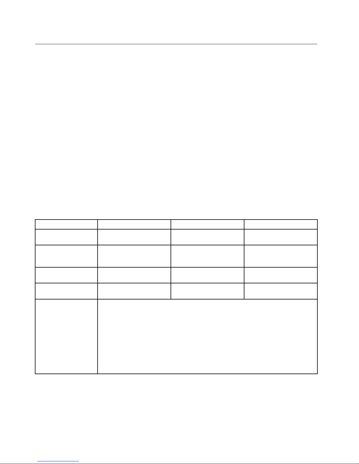
Table1.ASHRAEclassA2,classA3,andclassA4specifications
ASHRAEclassA2ASHRAEclassA3ASHRAEclassA4
Airtemperature
(operating)
10°Cto35°C(50°Fto95°F)5°Cto40°C(41°Fto104°F)5°Cto45°C(41°Fto113°F)
Airtemperature
(storage)
40°Cto60°C(-40°Fto
140°F)inoriginalshipping
package
40°Cto60°C(-40°Fto
140°F)inoriginalshipping
package
40°Cto60°C(-40°Fto
140°F)inoriginalshipping
package
Humidity(operating)
8%to80%
(non-condensing)
8%to85%
(non-condensing)
8%to90%
(non-condensing)
Humidity(storage)
8%to90%
(non-condensing)
8%to90%
(non-condensing)
8%to90%
(non-condensing)
Altitude
0to3048m(0to10000ft)inanunpressurizedenvironment
Note:Whenthealtitudeexceeds900m(2953ft),thedefinedmaximumdry-bulb
temperatureforoperationbecomesadependentvariable.
A2:Thetemperaturevaluedecreasesby1°C(33.8°F)withevery300m(984ft)of
altitudeincrease.
A3:Thetemperaturevaluedecreasesby1°C(33.8°F)withevery175m(574ft)of
altitudeincrease.
A4:Thetemperaturevaluedecreasesby1°C(33.8°F)withevery125m(410ft)of
altitudeincrease.
12ThinkServerRD650UserGuideandHardwareMaintenanceManual
Page 27

YourservercomplieswithASHRAEclassA2specifications.Dependingonthehardwareconfiguration,
someservermodelscomplywithASHRAEclassA3andclassA4specifications.TocomplywithASHRAE
classA3andclassA4specifications,theservermodelsmustmeetthefollowinghardwareconfiguration
requirementsatthesametime:
•Lenovo-qualifiedCPUexceptthefollowingtypes:
–135-wattCPU(4-core,6-core,or8-core)
–145-wattCPU(14-coreor18-core)
•Twopowersuppliesinstalledforredundancy
•Notthefull-length,full-heightPCIecardconfiguration(see“Rearviewoftheserver”onpage25
)
•TheLenovoThinkServerioMemorySX300PerformancePCIe2.0SSDbyFusionIOnotinstalled
Electricalinput
•Universalinput:
–Lowrange:
Minimum:100Vac
Maximum:127Vac
Inputfrequencyrange:50to60Hz
–Highrange:
Minimum:200Vac
Maximum:240Vac
Inputfrequencyrange:50to60Hz
Software
Thistopicprovidesinformationaboutthesoftwareprogramsthatyoucanusetosetup,use,andmaintain
theserver.
Todownloadthesoftwareprograms,gototheLenovoSupportWebsiteathttp://www.lenovo.com/support
andfollowtheinstructionsontheWebpage.
BIOSandTSMupdateutilities
TheBIOSandTSM(alsoknownasBMC)firmwarekeepsupdatingaftertheshipmentoftheserver.Lenovo
maintainspagesontheSupportWebsiteandprovidestheBIOSandTSMupdateutilitieswithinstructions
fordownloadtohelpyouupdatetheBIOSandTSMfirmwareifneeded.Formoreinformation,see“Updating
orrecoveringtheBIOS”onpage61
and“Updatingthefirmware”onpage65.
LenovoPartnerPackforMicrosoftSystemCenterOperations
Management
TheLenovoPartnerPackforMicrosoftSystemCenterOperationsManagementprogramautomatically
detectsthemanagedserversofyourThinkServerserverandprovidesdetailedsysteminformationaboutthe
managedservers.Thesysteminformationincludescomponentinventory,componentstatus,andsensor
status.Theprogramalsoenablesuserstoperformmanagementtasks,suchasrestartingorturningoffyour
ThinkServerserver,launchingaremoteconsole,andaccessingtheTSMinterface.
Fordetailedinformationaboutusingtheprogram,refertothehelpsystemoftheprogram.
Chapter3.Productoverview13
Page 28

LenovoThinkServerDeploymentManager
TheLenovoThinkServerDeploymentManagerprogram(hereinafterreferredtoasDeploymentManager)
simplifiestheprocessofconfiguringRAID,configuringBIOSsettings,andupdatingthefirmware.The
programworksinconjunctionwithyourWindowsorLinuxoperatingsysteminstallationdisctoautomatethe
processofinstallingtheoperatingsystemandassociateddevicedrivers.Theprogramispartoftheserver
firmware.Thehelpsystemfortheprogramcanbeaccesseddirectlyfromtheprograminterface.
DeploymentManagerhasthefollowingfeatures:
•Easy-to-use,language-selectableinterface
•Integratedhelpsystem
•Automatichardwaredetection
•Selectablepartitionsizeandfilesystemtype
•Abilitytoinstalltheoperatingsystemanddevicedriversinanunattendedmodetosavetime
•AbilitytocreateareusableresponsefilethatcanbeusedwithsimilarlyconfiguredLenovoserversto
makefutureinstallationsevenfaster
•ContainsRAIDconfigurationutility
•Providesdevicedriversbasedontheservermodelanddetecteddevices
•SupportsBIOSsettingsconfiguration
•Supportsfirmwareandapplicationsupdate
TouseDeploymentManager,dothefollowing:
1.Launchtheprogramthroughoneofthefollowingmethods:
•Turnontheserver.PressF10assoonasyouseethelogoscreen.Then,waitforseveralseconds.
DeploymentManageropens.
•StarttheSetupUtilityprogram.SelectBootManager➙LaunchTDM.DeploymentManageropens.
2.Readandacceptthelicenseagreement.
3.Selectthelanguageinwhichyouwanttoviewtheprogram.Then,followtheinstructionsonthe
screentousetheprogram.
BeforeinstallingaWindowsoraLinuxoperatingsystemusingDeploymentManager,itisrecommended
thatyoudothefollowing:
1.Downloadthelatestdevicedriverbundlefileforyourserver.Tofindanddownloadthebundlefile,goto
http://www.lenovo.com/driversandfollowtheinstructionsontheWebpage.
2.LaunchDeploymentManagerandclickPlatformUpdateontheleftpane.
3.SelectApplicationandthenclickNext.
4.ClickBrowsetoselectthecorrespondingbundlefileandthenclickOK.Theversioninformationis
displayed.
5.ClickFlashtoapplythebundlefileandupdatethecurrentdevicedrivers.
Note:IfyouwanttoinstallaVMwarehypervisororanyothersupportedoperatingsystemusingDeployment
Manager,thedevicedriverbundlefileisnotneeded.
TodownloadthelatestDeploymentManager,gotohttp://www.lenovo.com/driversandfollowthe
instructionsontheWebpage.
14ThinkServerRD650UserGuideandHardwareMaintenanceManual
Page 29

LenovoThinkServerDiagnostics
TheLenovoThinkServerDiagnosticsprogramenablesyoutodiagnoseserverproblems,performsome
diagnostictests,andcollectsysteminformation.Examplesofthesysteminformationincludebasic
operating-systeminformation,hardwareinformation,SEL,RAIDlog,andsoon.Dependingonthemodel,
yourservermightcomewithoneofthefollowingdiagnosticprograms:
•LenovoThinkserverDiagnosticsLinuxEdition
•LenovoThinkserverDiagnosticsStandaloneEdition
•LenovoThinkserverDiagnosticsWindowsEdition
FordetailedinformationaboutusingtheLenovoThinkServerDiagnosticsprogram,refertothehelpsystem
fortheprogram.
LenovoThinkServerEnergyManager
TheLenovoThinkServerEnergyManagerisatoolfordatacenterpowermanagement.Itmonitorsthepower
andtemperatureatthedevicelevelandthegrouplevel.Bymonitoringandanalyzingpowerandtemperature
information,EnergyManagerhelpsyoutoincreasepowerefficiencyandimprovebusinesscontinuity.
ForinformationaboutusingEnergyManager,refertothehelpsystemoftheprogram.
LenovoThinkServerPowerPlanner
TheLenovoThinkServerPowerPlannerprogramprovidesinformationaboutdatamaintenance,power
consumption,electriccurrentcalculations,andsoon.Theprogramhelpsyouconvenientlymanageservers
anddevicestoincreasethedeploymentefficiencysignificantly.
FordetailedinformationaboutusingtheLenovoThinkServerPowerPlannerprogram,refertothehelp
systemoftheprogram.
LenovoThinkServerSystemManager
TheLenovoThinkServerSystemManager(TSM)isamanagementsolutionthatprovidescomprehensive
andsecuremanagementfeatures.Thesefeaturesenableyoutomanageyourserversremotelyusing
aone-to-oneorone-to-manymethod.
TheTSMprovidesaone-to-oneweb-basedconsole.Theweb-basedconsoleisdevelopedinHTML5and
structuredinthewaythatmakesplatformmanagementintuitiveandefficient.TheTSMalsoprovidesa
securecommand-lineinterfaceforimprovedefficiencyandfunctionality.
FordetailedinformationaboutusingtheLenovoThinkServerSystemManagerprogram,refertothehelp
systemoftheprogram.
LenovoThinkServerSystemManagerPremium
LenovoThinkServerSystemManagerPremiumprovidesyouasolutionthatenablesyoutoreceiveallthe
benefitsandfeaturesprovidedbyboththeLenovoThinkServerSystemManagerprogramandtheLenovo
ThinkServerEnergyManagerprogram.ItalsoenablesyoutocontroltheserverremotelyusingLenovovirtual
keyboard,video,andmouse.
Fordetailedinformationaboutusingtheprogram,refertothehelpsystemoftheprogram.
Chapter3.Productoverview15
Page 30
Locations
Thistopicprovidesinformationtohelpyoulocateyourservercomponents.
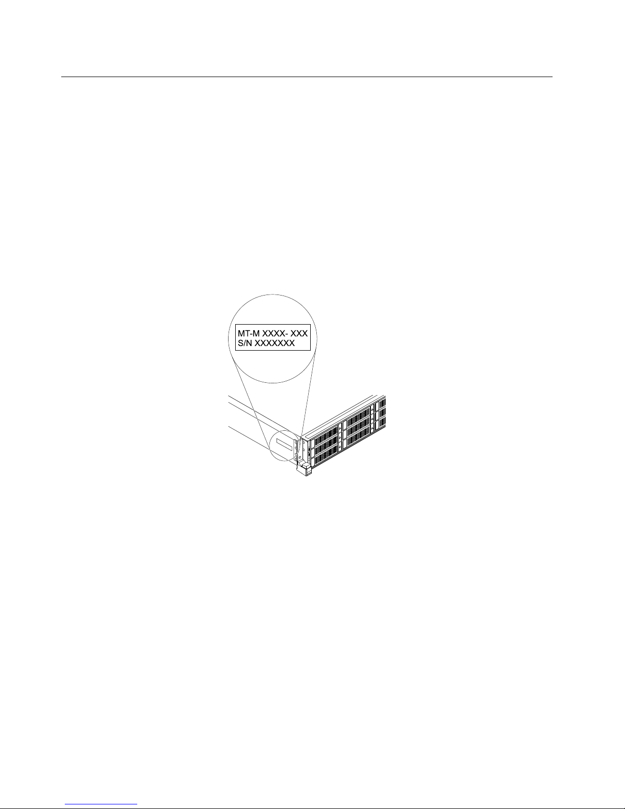
Machinetype,model,andserialnumberlabel
Thistopichelpsyoutolocatethelabelthatcontainsthemachinetype,model,andserialnumberinformation
foryourserver.
WhenyoucontactLenovoforhelp,themachinetype,model,andserialnumberinformationhelpssupport
technicianstoidentifyyourserverandprovidefasterservice.
Thefollowingillustrationsareexamplesofthemachinetype,model,andserialnumberlabelsonserver
modelswithdifferentdrivebayconfigurations.
Note:Dependingonthemodel,yourservermightlookslightlydifferentfromtheillustrationsinthistopic.
Figure1.Labelonservermodelswith3.5-inch-drivebays
16ThinkServerRD650UserGuideandHardwareMaintenanceManual
Page 31
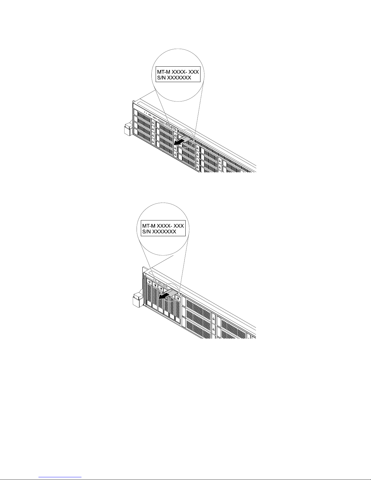
Figure2.Labelonservermodelswith2.5-inch-drivebays
Figure3.Labelonservermodelswith2.5-inch/3.5-inchmixeddrivebays
Frontviewoftheserver
Thefrontviewoftheservervariesbymodel.Theillustrationsinthistopicshowtheserverfrontviews
basedonthesupportedinternaldrives:
•“Frontviewofservermodelswith3.5-inchdrives”onpage18
•“Frontviewofservermodelswith2.5-inchdrives”onpage19
•“Frontviewofservermodelswithboth2.5-inchdrivesand3.5-inchdrives”onpage20
•“Frontviewofservermodelswithaslimopticaldrive”onpage21
•“Frontviewofservermodelswithaninternaltapedrive”onpage22
Chapter3.Productoverview17
Page 32
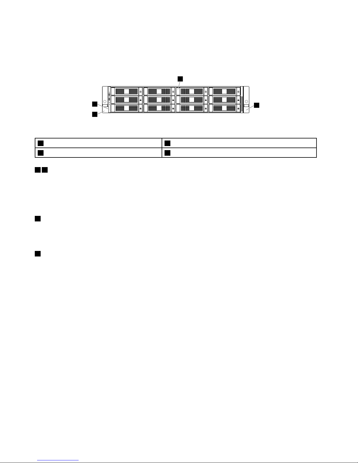
Note:Dependingonthemodel,yourservermightlookslightlydifferentfromtheillustrationsinthistopic.
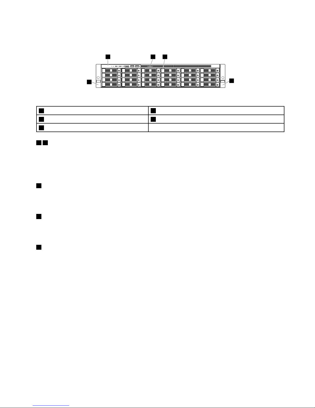
Frontviewofservermodelswith3.5-inchdrives
1
2
3
4
0
1
2
3
4
5
6
7
8
9
10
11
Figure4.Frontviewofservermodelswith3.5-inchdrives
1Rackhandle(left)
2Frontpanel
33.5-inch-drivebays(0–11)4Rackhandle(right)
14Rackhandles
Ifyourserverisinstalledinarackcabinet,youcanusetherackhandlestohelpyouslidetheserveroutof
therackcabinet.Youalsocanusetherackhandlesandscrewstosecuretheserverintherackcabinetso
thattheservercannotslideout,especiallyinvibration-proneareas.Formoreinformation,refertotheRack
InstallationInstructionsthatcomeswithyourserver.
2Frontpanel
Forinformationaboutthecontrols,connectors,andstatusLEDsonthefrontpanel,see“Frontpanel”
onpage23.
33.5-inch-drivebays(0–11)
TheEMIintegrityandcoolingoftheserverareprotectedbyhavingalldrivebayscoveredoroccupied.
Thenumberoftheinstalleddrivesinyourservervariesbymodel.Thevacantdrivebaysareoccupied
bydummytrays.
Whenyouinstalldrives,followtheorderofthedrivebaynumbers.
Iftheserversupportsuptosixdrives,anEMI-protectivepanelcoversthebays6–11asawhole.
18ThinkServerRD650UserGuideandHardwareMaintenanceManual
Page 33
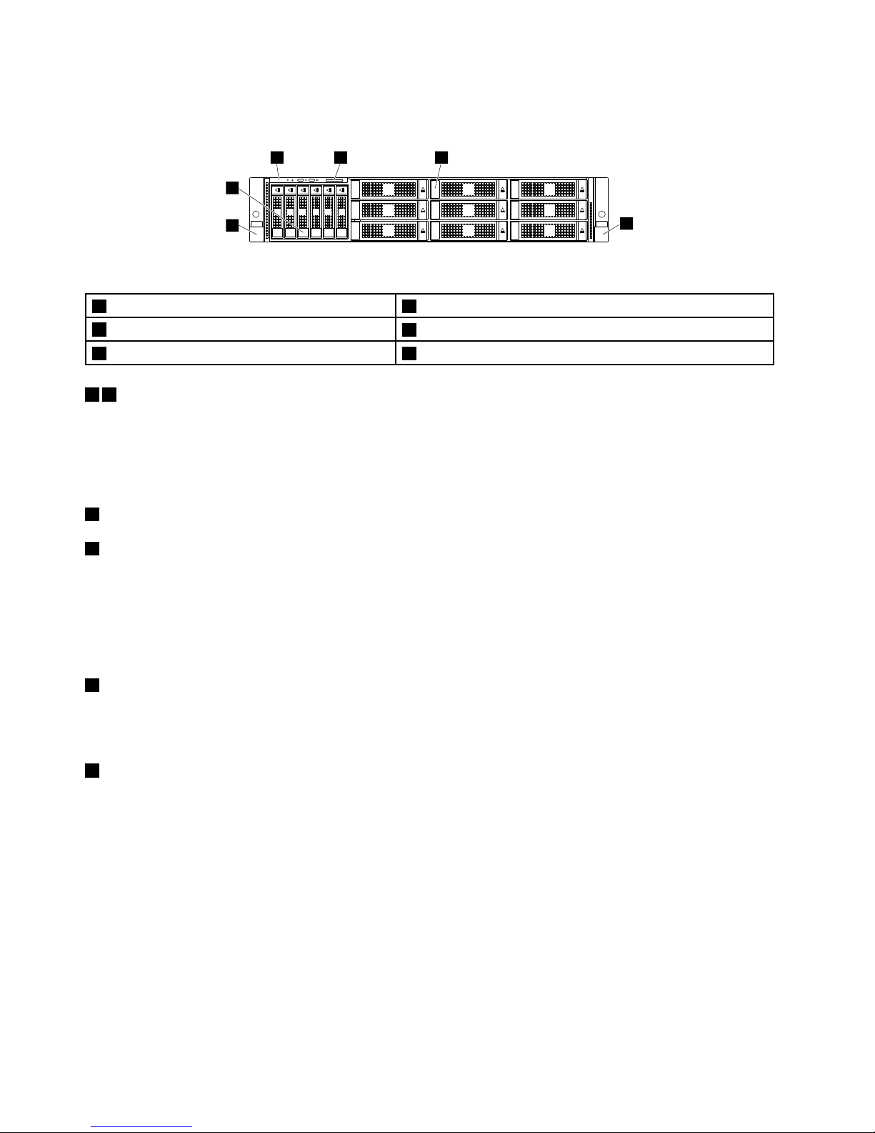
Frontviewofservermodelswith2.5-inchdrives
5
2 3 4
1
0
1
2
3
4
5
6
7
8
9
10
11
12
13
14
15
16
17
18
19
20
21
22
23
Figure5.Frontviewofservermodelswith2.5-inchdrives
1Rackhandle(left)
2Frontpanel
3Pull-outinformationcard
42.5-inch-drivebays(0–23)
5Rackhandle(right)
15Rackhandles
Ifyourserverisinstalledinarackcabinet,youcanusetherackhandlestohelpyouslidetheserveroutof
therackcabinet.Youalsocanusetherackhandlesandscrewstosecuretheserverintherackcabinetso
thattheservercannotslideout,especiallyinvibration-proneareas.Formoreinformation,refertotheRack
InstallationInstructionsthatcomeswithyourserver.
2Frontpanel
Forinformationaboutthecontrols,connectors,andstatusLEDsonthefrontpanel,see“Frontpanel”
onpage23
.
3Pull-outinformationcard
Themachinetype,model,andserialnumberlabeloftheserverisattachedonthepull-outinformationcard.
See“Machinetype,model,andserialnumberlabel”onpage16.
42.5-inch-drivebays(0–23)
TheEMIintegrityandcoolingoftheserverareprotectedbyhavingalldrivebayscoveredoroccupied.
Thenumberoftheinstalleddrivesinyourservervariesbymodel.Thevacantdrivebaysareoccupied
bydummytrays.
Whenyouinstalldrives,followtheorderofthedrivebaynumbers.
Dependingonyourservermodel,allorsomeofthedrive-baygroups,suchasbays0–7,bays8–15,and
bays16–23,mightbecoveredbyEMI-protectivepanelsasawhole.
Chapter3.Productoverview19
Page 34
Frontviewofservermodelswithboth2.5-inchdrivesand3.5-inchdrives
0 1 2 3 4 5
1
2
3 4 5
6
6
7
8
9
10
11
12
13
14
Figure6.Frontviewofservermodelswithboth2.5-inchdrivesand3.5-inchdrives
1Rackhandle(left)22.5-inch-drivebays(0–5)
3Frontpanel
4Pull-outinformationcard
53.5-inch-drivebays(6–14)6Rackhandle(right)
16Rackhandles
Ifyourserverisinstalledinarackcabinet,youcanusetherackhandlestohelpyouslidetheserveroutof
therackcabinet.Youalsocanusetherackhandlesandscrewstosecuretheserverintherackcabinetso
thattheservercannotslideout,especiallyinvibration-proneareas.Formoreinformation,refertotheRack
InstallationInstructionsthatcomeswithyourserver.
22.5-inch-drivebays(0–5)
53.5-inch-drivebays(6–14)
TheEMIintegrityandcoolingoftheserverareprotectedbyhavingalldrivebayscoveredoroccupied.
Thenumberoftheinstalleddrivesinyourservervariesbymodel.Thevacantdrivebaysareoccupied
bydummytrays.
Whenyouinstalldrives,followtheorderofthedrivebaynumbers.
3Frontpanel
Forinformationaboutthecontrols,connectors,andstatusLEDsonthefrontpanel,see“Frontpanel”
onpage23.
4Pull-outinformationcard
Themachinetype,model,andserialnumberlabeloftheserverisattachedonthepull-outinformationcard.
See“Machinetype,model,andserialnumberlabel”onpage16.
20ThinkServerRD650UserGuideandHardwareMaintenanceManual
Page 35
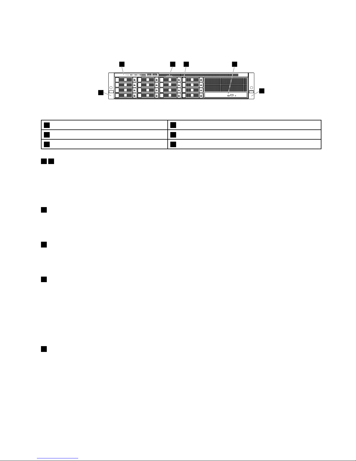
Frontviewofservermodelswithaslimopticaldrive
6
2 3 4
1
5
0
1
2
3
4
5
6
7
8
9
10
11
12
13
14
15
Figure7.Frontviewofservermodelswithaslimopticaldrive
1Rackhandle(left)
2Frontpanel
3Pull-outinformationcard
42.5-inch-drivebays(0–15)
5Slimopticaldrive(availableonsomemodels)6Rackhandle(right)
16Rackhandles
Ifyourserverisinstalledinarackcabinet,youcanusetherackhandlestohelpyouslidetheserveroutof
therackcabinet.Youalsocanusetherackhandlesandscrewstosecuretheserverintherackcabinetso
thattheservercannotslideout,especiallyinvibration-proneareas.Formoreinformation,refertotheRack
InstallationInstructionsthatcomeswithyourserver.
2Frontpanel
Forinformationaboutthecontrols,connectors,andstatusLEDsonthefrontpanel,see“Frontpanel”
onpage23
.
3Pull-outinformationcard
Themachinetype,model,andserialnumberlabeloftheserverisattachedonthepull-outinformationcard.
See“Machinetype,model,andserialnumberlabel”onpage16.
42.5-inch-drivebays(0–15)
TheEMIintegrityandcoolingoftheserverareprotectedbyhavingalldrivebayscoveredoroccupied.
Thenumberoftheinstalleddrivesinyourservervariesbymodel.Thevacantdrivebaysareoccupied
bydummytrays.
Whenyouinstalldrives,followtheorderofthedrivebaynumbers.
Iftheserversupportsuptoeightdrives,anEMI-protectivepanelcoversthebays8–15asawhole.
5Slimopticaldrive
SomeservermodelscomewithaslimSATAopticaldrive(DVD-RWorDVD-ROM).
Chapter3.Productoverview21
Page 36
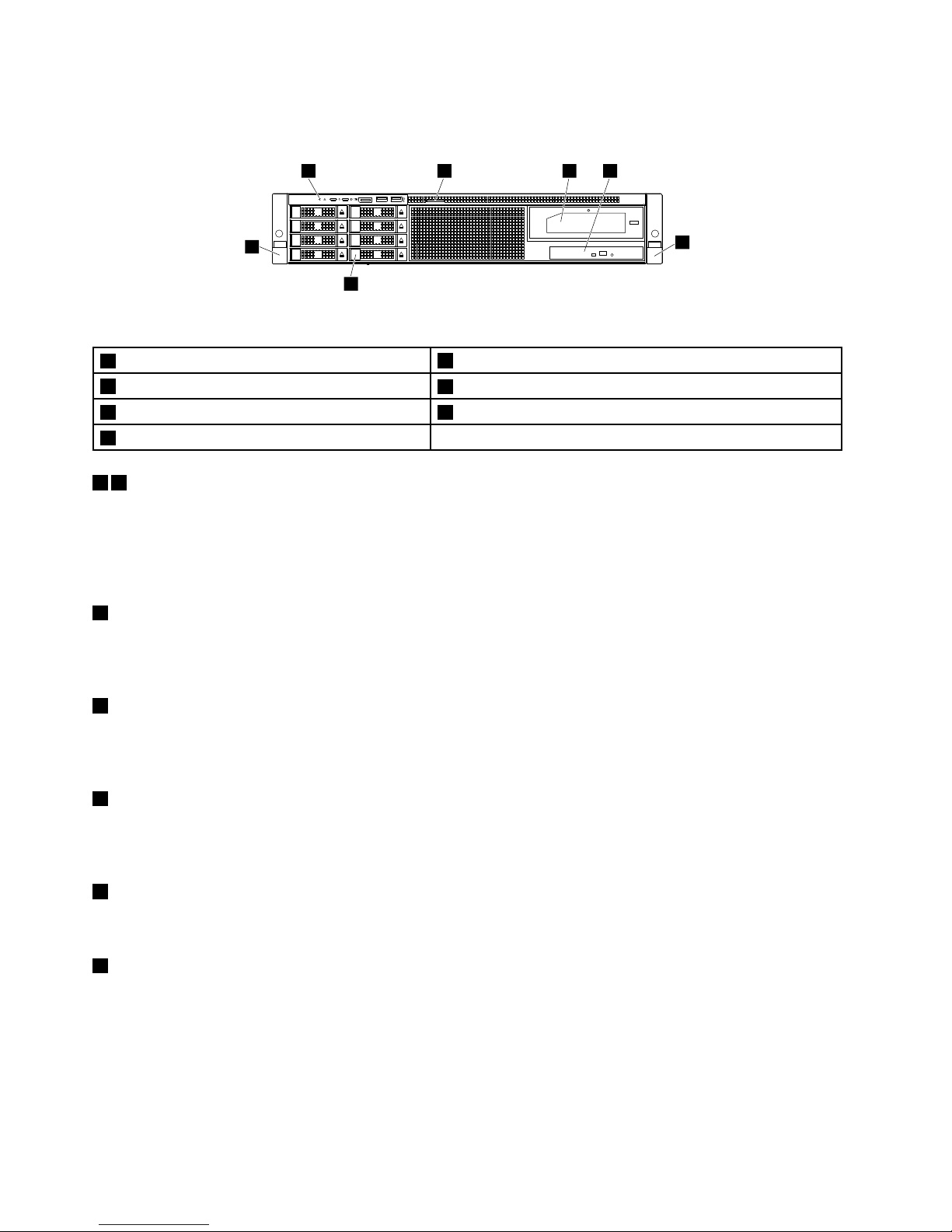
Frontviewofservermodelswithaninternaltapedrive
6
7
2 3 4
1
5
0
1
2
3
4
5
6
7
Figure8.Frontviewofservermodelswithaninternaltapedrive
1Rackhandle(left)
2Frontpanel
3Pull-outinformationcard
4Internaltapedrive(availableonsomemodels)
5Slimopticaldrive(availableonsomemodels)6Rackhandle(right)
72.5-inch-drivebays(0–7)
16Rackhandles
Ifyourserverisinstalledinarackcabinet,youcanusetherackhandlestohelpyouslidetheserveroutof
therackcabinet.Youalsocanusetherackhandlesandscrewstosecuretheserverintherackcabinetso
thattheservercannotslideout,especiallyinvibration-proneareas.Formoreinformation,refertotheRack
InstallationInstructionsthatcomeswithyourserver.
2Frontpanel
Forinformationaboutthecontrols,connectors,andstatusLEDsonthefrontpanel,see“Frontpanel”
onpage23
.
3Pull-outinformationcard
Themachinetype,model,andserialnumberlabeloftheserverisattachedonthepull-outinformationcard.
See“Machinetype,model,andserialnumberlabel”onpage16
.
4Internaltapedrive
Someservermodelscomewithaninternaltapedrive.Theinternaltapedriveenablesyoutostoredataon
tapes.
5Slimopticaldrive
SomeservermodelscomewithaslimSATAopticaldrive(DVD-RWorDVD-ROM).
72.5-inch-drivebays(0–7)
TheEMIintegrityandcoolingoftheserverareprotectedbyhavingalldrivebayscoveredoroccupied.
Thenumberoftheinstalleddrivesinyourservervariesbymodel.Thevacantdrivebaysareoccupied
bydummytrays.
Whenyouinstalldrives,followtheorderofthedrivebaynumbers.
22ThinkServerRD650UserGuideandHardwareMaintenanceManual
Page 37
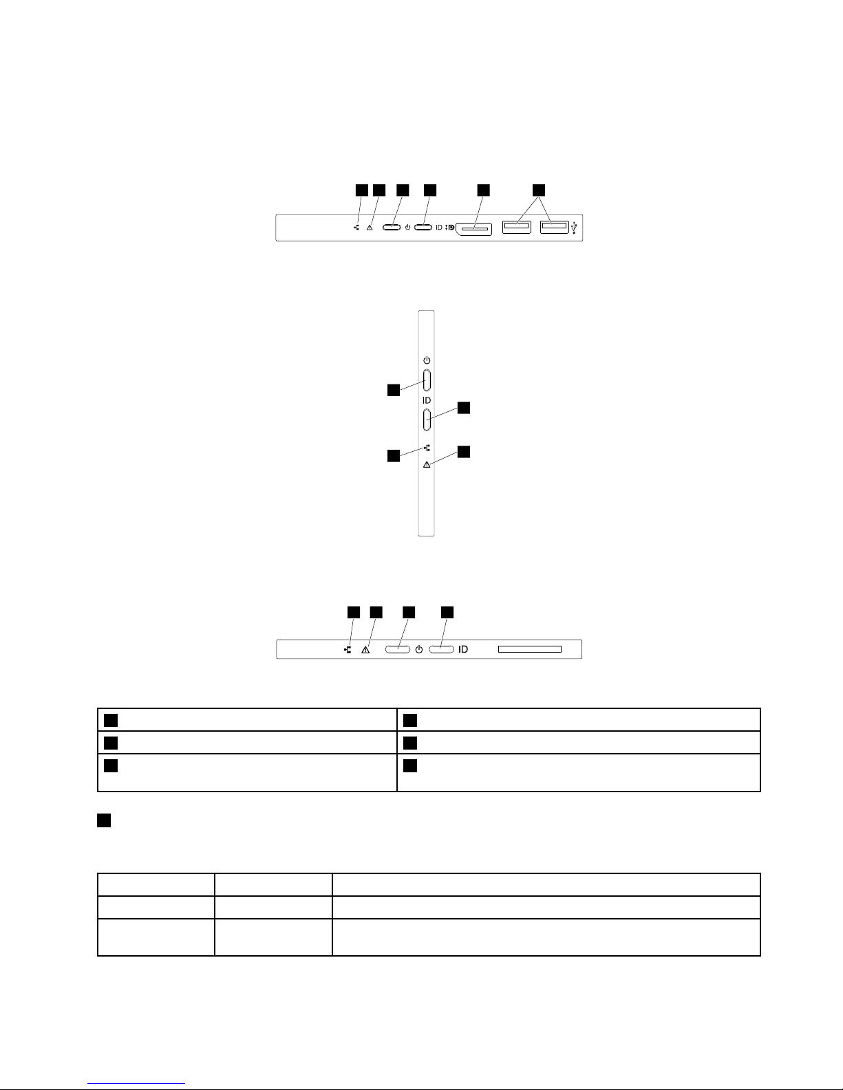
Frontpanel
Thefollowingillustrationsshowthecontrols,connectors,andLEDsonthefrontpaneloftheserver.Tolocate
thefrontpanel,see“Frontviewoftheserver”onpage17.
1 2 3 4 5 6
Figure9.Frontpanelofservermodelswith2.5-inch-drivebays
1
3
2
4
Figure10.Frontpanelofservermodelswith3.5-inch-drivebays
1 2 3 4
Figure11.Frontpanelofservermodelswith2.5-inch/3.5-inchmixeddrivebays
1NetworkstatusLED
2SystemhealthLED
3PowerbuttonwithpowerstatusLED
4SystemIDbuttonwithIDLED
5DisplayPortconnector(availableonsome
models)
6USB2.0connectors(2)(availableonsomemodels)
1NetworkstatusLED
ThenetworkstatusLEDonthefrontpanelhelpsyouidentifytheAnyFabricnetworkconnectivityandactivity.
StatusColor
Description
Blinking
Green
TheAnyFabricnetworkisconnectedandactive.
Off
None
TheserverisdisconnectedfromtheAnyFabricnetworkortheAnyFabric
networkisnotactive.
Chapter3.Productoverview23
Page 38
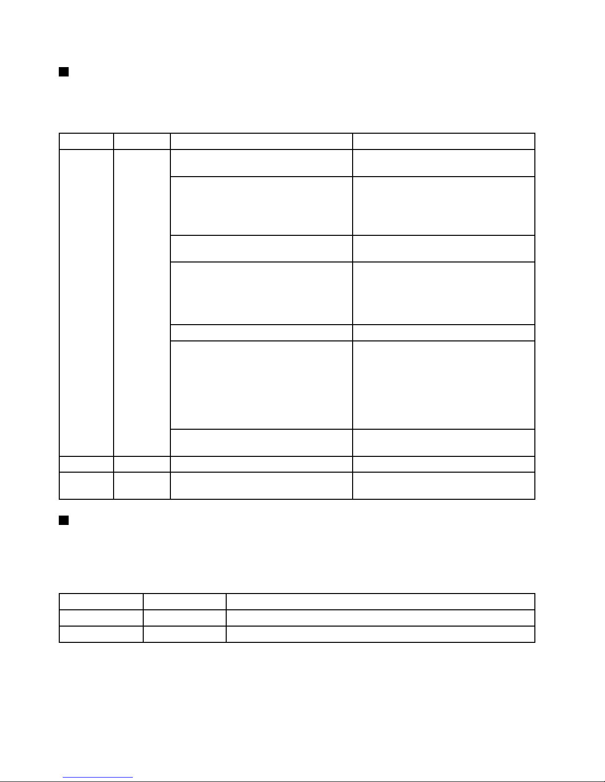
2SystemhealthLED
ThesystemhealthLEDprovidesbasicdiagnosticfunctionsforyourserver.IfthesystemhealthLEDislit,
oneormoreLEDselsewhereintheservermightalsobelittodirectyoutothesourceoftheerror.See
“SystemfanfaultLEDs”onpage49
.
StatusColor
DescriptionAction
Thetemperatureoftheserverreachedthe
non-criticaltemperaturethreshold.
ChecktheBMCforerrorsandcheckthe
systemfans.
Thevoltageoftheserverreachedthe
non-criticalvoltagethreshold.
Replacethesystemboard.
Note:Thisproceduremustbeperformed
onlybytrainedservicepersonnelofLenovo.
SeeChapter8“Gettinginformation,help,
andservice”onpage193
.
Afanhasbeendetectedtoberunningat
lowspeed.
Checkthesystemfans.
Ahot-swapfanhasbeenremoved.1.Ensurethatthesystemfansare
connectedsecurelytothesystem
board.
2.Reinstalltheremovedfanorinstalla
newfantoreplacetheremovedfan.
Thepowersupplyhasacriticalerror.
ChecktheBMCfordetailedinformation.
Thepowercordhasbeendisconnected
fromonepowersupplyoraredundant
powersupplyhasbeenremoved.
1.Ensurethatthepowersuppliesare
installedsecurelyintheserver.
2.Ensurethatthepowercordsare
connectedsecurelytothepower
supplies.
3.Installanewpowersupplytoreplace
theremovedone.
On
Amber
TheTHERMTRIP#signalisasserted
becausethesystemisoverheated.
ChecktheBMCforerrorsandthencheck
thesystemfans.
BlinkingAmberTheserverisinitialized.
Off
None
Theserverisoffortheserverisonandis
workingcorrectly.
3PowerbuttonwithpowerstatusLED
Youcanpressthepowerbuttontoturnontheserverwhenyoufinishsettinguptheserver.Youalsocan
holdthepowerbuttonforseveralsecondstoturnofftheserverifyoucannotturnofftheserverfromthe
operatingsystem.SeeChapter4“Turningonandturningofftheserver”onpage53.ThepowerstatusLED
helpsyoutodeterminethecurrentpowerstatus.
StatusColor
Description
OnGreen
Theserverison.
Off
None
Theserverisoff.
24ThinkServerRD650UserGuideandHardwareMaintenanceManual
Page 39
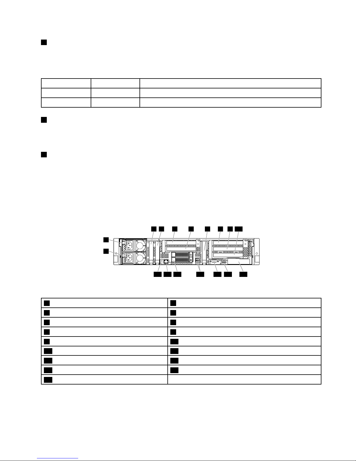
4SystemIDbuttonwithIDLED
WhenyoupresstheIDbuttononthefrontpanel,theIDLEDsonboththefrontandrearoftheserverare
littohelpyoulocatetheserveramongotherservers.Y oualsocanturnontheIDLEDsusingaremote
managementprogramforserverpresencedetection.
StatusColor
Description
On
Blue
Theserverisidentified.
Off
None
TheIDLEDisnotinuseortheserverisnotidentified.
5DisplayPortconnector
Usedtoattachahigh-performancemonitor,adirect-drivemonitor,orotherdevicesthatuseaDisplayPort
connector.
6FrontUSB2.0connectors(2)
UsedtoattachaUSB-compatibledevice,suchasaUSBkeyboard,mouse,scanner,orprinter.Ifyou
havemorethansixUSBdevices,youcanpurchaseaUSBhub,whichyoucanusetoconnectadditional
USBdevices.
Rearviewoftheserver
Thistopicprovidesinformationtohelpyoulocatetheconnectorsandcomponentsontherearofyourserver.
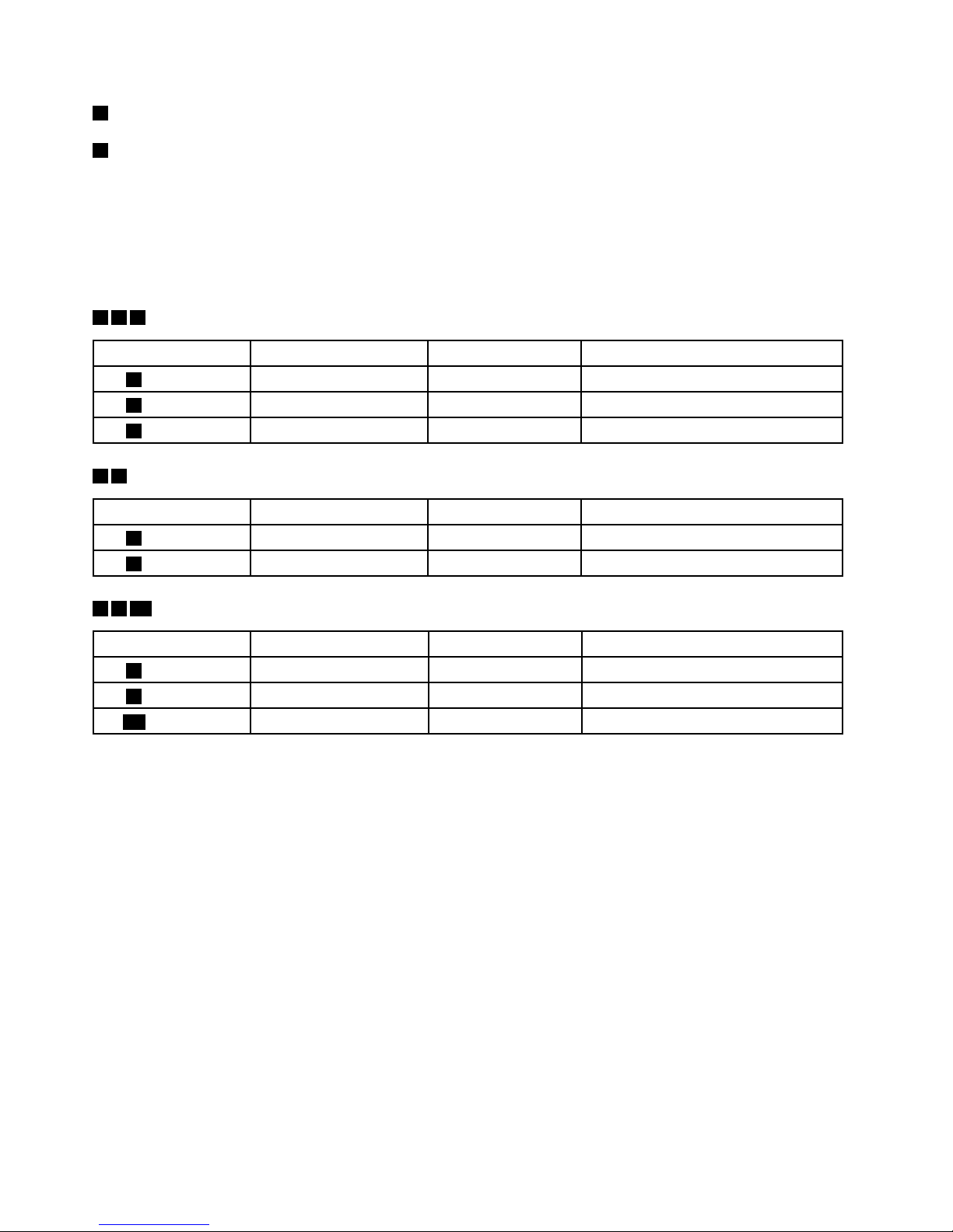
1
2
3 4 5 6 7 8 9 10
111213151617 14
Figure12.Rearviewoftheserver
1Powersupply2(availableonsomemodels)
2Powersupply1
3PCIeslot84PCIeslot7
5PCIeslot5(onrisercardassembly2)6PCIeslot6(onrisercardassembly2)
7PCIeslot48PCIeslot1(onrisercardassembly1)
9PCIeslot2(onrisercardassembly1)10PCIeslot3(onrisercardassembly1)
11AnyFabricslot12DisplayPortconnector
13Serialconnector14USB3.0connectors(2)
152.5-inch-drivebays(2)16Ethernetconnectorforsystemmanagement(RJ-45)
17SystemIDLED
Chapter3.Productoverview25
Page 40
1Powersupply2(availableonsomemodels)
2Powersupply1
Thehot-swapredundantpowersupplieshelpyouavoidsignificantinterruptiontotheoperationofthe
systemwhenapowersupplyfails.Y oucanpurchaseapowersupplyoptionfromLenovoandinstallthe
powersupplytoprovidepowerredundancywithoutturningofftheserver.
Oneachpowersupply,therearethreestatusLEDsnearthepowercordconnector.Forinformationabout
thestatusLEDs,see“PowersupplystatusLEDs”onpage51.
347PCIeslotsonthesystemboard
Slot
PhysicallinkwidthNegotiablelinkwidth
Supportedcardlengthandheight
3PCIeslot8
x16x8,x4,x2,x1
Low-profilecard
4PCIeslot7
x16x8,x4,x2,x1
Low-profilecard
7PCIeslot4
x16x8,x4,x2,x1
Low-profilecard
56PCIeslotsonrisercardassembly2
Slot
PhysicallinkwidthNegotiablelinkwidth
Supportedcardlengthandheight
5PCIeslot5
x16x8,x4,x2,x1
Half-length,full-heightcard
6PCIeslot6
x16x8,x4,x2,x1
Half-length,full-heightcard
8910PCIeslotsonrisercardassembly1
Slot
PhysicallinkwidthNegotiablelinkwidth
Supportedcardlengthandheight
8PCIeslot1
x16x8,x4,x2,x1
Half-length,full-heightcard
9PCIeslot2
x16x8,x4,x2,x1
Half-length,full-heightcard
10PCIeslot3
x16x8,x4,x2,x1
Half-length,full-heightcard
26ThinkServerRD650UserGuideandHardwareMaintenanceManual
Page 41
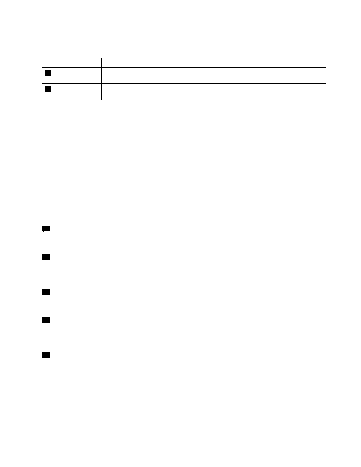
Note:Forservermodelswith2.5-inch-drivebays,youcaninstallfull-length,full-heightPCIecardsintothe
correspondingPCIeslotsontherisercardassemblies.
Slot
PhysicallinkwidthNegotiablelinkwidth
Supportedcardlengthandheight
5PCIeslot5(onriser
cardassembly2)
x16x16,x8,x4,x2,x1
Full-length,full-heightcard
8PCIeslot1(onriser
cardassembly1)
x16x16,x8,x4,x2,x1
Full-length,full-heightcard
Thefull-length,full-heightPCIecardconfigurationmustmeetthefollowingrequirements:
•Theambienttemperature(operating)rangesfrom10°C(50°F)to35°C(95°F).See“Specifications”on
page12.
•ThePCIecardtobeinstalledisnotageneral-purposecomputingongraphicsprocessingunits(GPGPU).
•Themicroprocessorhasamaximumof120-wattthermaldesignpower.
•Nointernaltapedriveisinstalled.
•Thefollowinghardwarecomponentsareinstalled:
–Heatsinkthatsupports1Uservers(“U”istheunitofmeasurementfordefiningtheverticalspaceused
byyourserver.1Uisequivalentto4.445cmor1.75inches.)
–Risercardbracketthatsupportsfull-length,full-heightPCIecard
–Coolingshroudthatsupportsfull-length,full-heightPCIecard
–Dummymemorymodulesthatareinstalledintheunoccupiedmemoryslots
11AnyFabricslot
UsedtoinstallanAnyFabricadapter(alsocalledmezzanineadapter).
12DisplayPortconnector
Usedtoattachahigh-performancemonitor,adirect-drivemonitor,orotherdevicesthatuseaDisplayPort
connector.
13Serialconnector
Usedtoattachadevicethatusesa9-pinserialconnector.
14USB3.0connectors(2)
UsedtoattachadevicethatrequiresaUSB2.0or3.0connection,suchasakeyboard,amouse,ascanner,
aprinter,orapersonaldigitalassistant(PDA).
152.5-inch-drivebays(2)
Usedtoinstalltwo2.5-inchdrives.
Chapter3.Productoverview27
Page 42
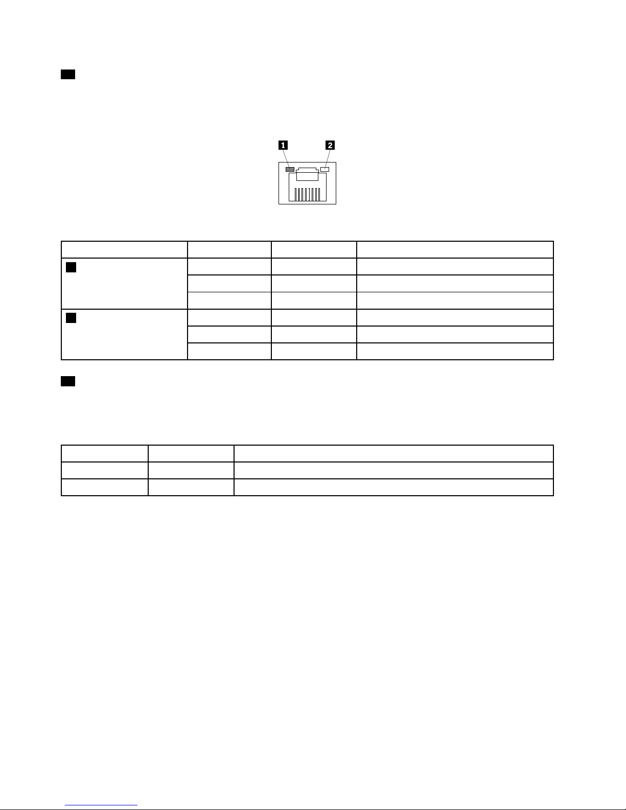
16Ethernetconnectorforsystemmanagement(RJ-45)
UsedtoattachanEthernetcableforaLAN.TheEthernetconnectorhastwostatusLEDstohelpyouidentify
theEthernetconnectivity,activity,andconnectionspeed.
Figure13.EthernetstatusLEDs
EthernetstatusLED
ColorStatus
Description
Amber
On
Theconnectionspeedis1000Mbps.
GreenOn
Theconnectionspeedis100Mbps.
1Left:dataspeed
None
Off
Theconnectionspeedis10Mbps.
GreenOn
TheserverisconnectedtoaLAN.
None
Off
TheserverisdisconnectedfromaLAN.
2Right:linkandactivity
Green
BlinkingTheLANisconnectedandactive.
17SystemIDLED
WhenyoupresstheIDbuttononthefrontpanel,theIDLEDsonboththefrontandrearoftheserverare
littohelpyoulocatetheserveramongotherservers.Y oualsocanturnontheIDLEDsusingaremote
managementprogramforserverpresencedetection.
StatusColor
Description
On
Blue
Theserverisidentified.
Off
None
TheIDLEDisnotinuseortheserverisnotidentified.
Servercomponents
Thistopicprovidesinformationtohelpyoulocatethecomponentsofyourserver.Formoreinformation
aboutmajorcomponents,seetherelatedtopicsin“Locations”onpage16.
Toremovetheservercoverandgainaccesstotheinsideoftheserver,see“Removingtheservercover”
onpage69.
28ThinkServerRD650UserGuideandHardwareMaintenanceManual
Page 43
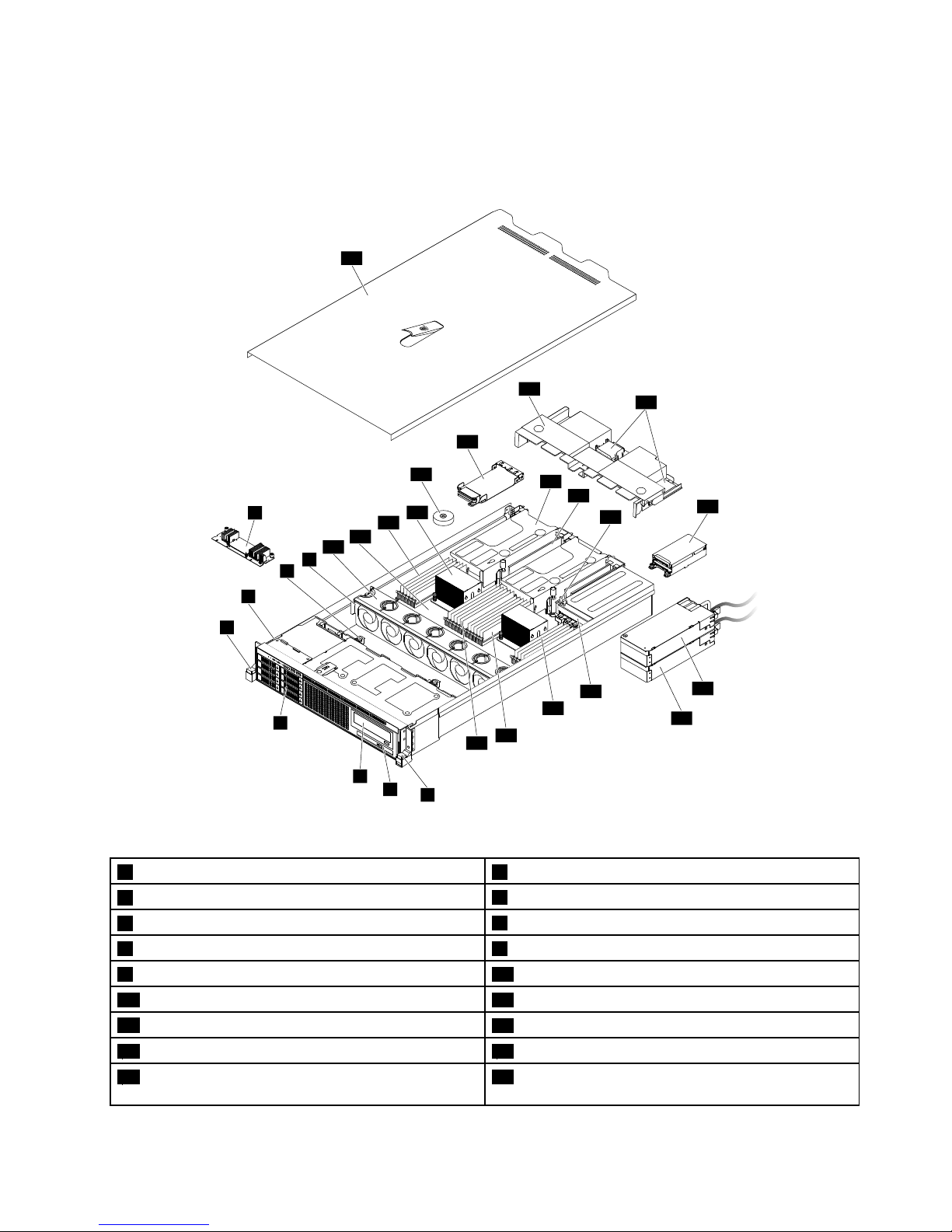
Thefollowingillustrationshowsthecomponentsofservermodelswithaninternaltapedriveandaslim
opticaldrive.
Note:Dependingonthemodel,yourservermightlookslightlydifferentfromtheillustrationinthistopic.
5
6
8
1
2
3
4
7
9
10
12
27
26
25
24
13
14
18
19
20
15
16
17
28
11
22
23
21
Figure14.Componentsofservermodelswithaninternaltapedriveandaslimopticaldrive
1Rackhandle(right)2Slimopticaldrive(availableonsomemodels)
3Internaltapedrive(availableonsomemodels)
42.5-inch-drivearea
5Rackhandle(left)
6Frontpanelboard
7AnyRAIDadapter8Frontbackplane
9Systemfancage10Systemfan
11Systemboard12CPU1DIMMs(varybymodel)
13Heatsink
14Coin-cellbattery
15AnyFabricadapter(availableonsomemodels)16Coolingshroud
17ThinkServerRAIDSuperCapacitorModule(available
onsomemodels)
18Risercardassembly
Chapter3.Productoverview29
Page 44
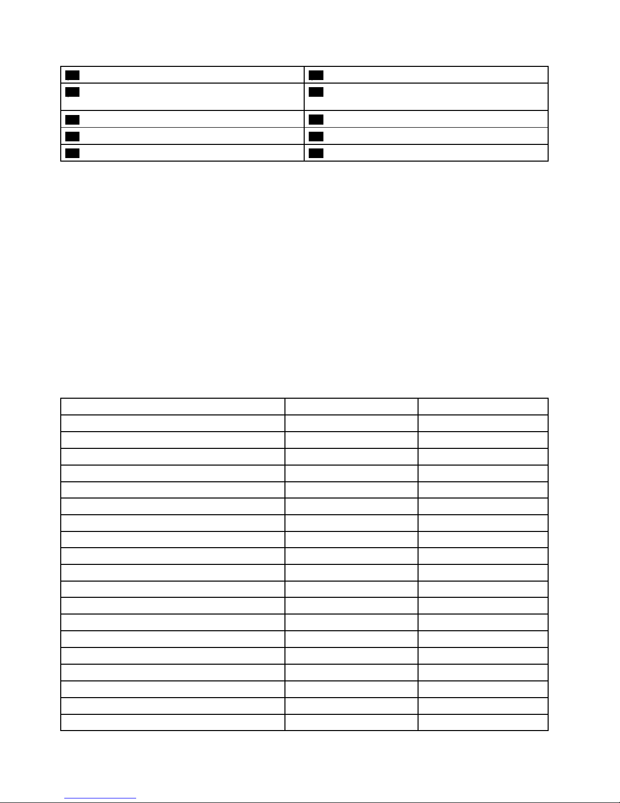
19PCIecard(availableonsomemodels)20Intrusionswitch(availableonsomemodels)
21Rearbackplane/cageassembly(availableonsome
models)
22Powersupply1
23Powersupply2(availableonsomemodels)
24Powerdistributionboard
25CPU2DIMMs(varybymodel)26CPU2DIMMs(varybymodel)
27CPU1DIMMs(varybymodel)28Servercover
CRUsarepartsthatcanbeupgradedorreplacedbythecustomer.IfaCRUisdeterminedtobedefective
duringthewarrantyperiod,areplacementCRUwillbeprovidedtothecustomer.Customersareresponsible
forinstallingtheself-serviceCRUsforthisproduct.Customersalsocaninstalloptional-serviceCRUs,which
mightrequiresometechnicalskillsortools,orrequestthatatechnicianinstalltheoptional-serviceCRU
underthetermsoftheapplicablewarrantyservicetypeforyourcountryorregion.
Non-CRUsmustbereplacedonlybytrainedservicetechnicians.
ThefollowingtableliststhemajorFRUsinyourserverandtheCRUidentificationinformation.Foracomplete
listingofFRUinformation,suchasFRUpartnumbersandsupportedservermodels,goto:
http://www.lenovo.com/serviceparts-lookup
Notes:
•BeforeservicingaLenovoproduct,ensurethatyoureadandunderstand“Safetyinformation”onpageiii
.
•UseonlypartsprovidedbyLenovo.
*Availableonsomemodels
FRUdescription
Self-serviceCRUOptional-serviceCRU
AnyFabricadapter*YesNo
AnyRAIDadapterNoYes
Coin-cellbattery
YesNo
Coolingshroud
YesNo
FrontbackplaneNoYes
FrontpanelboardYesNo
HeatsinkYesNo
Hot-swapstoragedrive*YesNo
Hot-swapredundantpowersupplyYesNo
Internaltapedrive*YesNo
Intrusionswitch*YesNo
LenovoThinkServerRAID110ipass-throughboard
NoYes
LenovoThinkServerRAID110iupgradekey*
YesNo
LenovoThinkServerRAID510iupgradekey*
YesNo
MemorymoduleYesNo
MicroprocessorNoYes
Opticaldrive*
YesNo
PCIecard*
YesNo
PowercordYesNo
30ThinkServerRD650UserGuideandHardwareMaintenanceManual
Page 45
FRUdescription
Self-serviceCRUOptional-serviceCRU
PowerdistributionboardNoNo
RearbackplaneYesNo
Rearbackplane/cageassembly*
YesNo
RisercardYesNo
Securedigital(SD)module*
NoYes
Systemboard
NoNo
Systemfan
YesNo
Systemfancage
YesNo
ThinkServerRAIDSuperCapacitorModule*
YesNo
ThinkServerSystemManagerPremium*
YesNo
ThinkServerTrustedPlatformModule*
YesNo
AnyRAIDadapter,RAIDcard,andpass-throughboard
ThistopicprovidesinformationtohelpyoulocatetheconnectorsontheAnyRAIDadapter,RAIDcard,
andpass-throughboard.
TheAnyRAIDadapterandRAIDcardprovideadvancedSATA/SAShardwareRAIDfunctions.The
pass-throughboardprovidesSATAsoftwareRAIDfunction.YoucanpurchaseasupportedAnyRAID
adapter,RAIDcard,orpass-throughboardfromLenovoandinstallitintotheserver.
ForalistofThinkServeroptions,goto:
http://lenovoquickpick.com/usa/home/thinkserver/rack-and-tower-server
Note:TheoptionkitforAnyRAIDadapter,RAIDcard,orpass-throughboardisdesignedfordifferenttypes
ofserversandmightcontainadditionalcablesthatarenotrequiredforyourserver.
Toinstall,remove,orreplacetheAnyRAIDadapterorpass-throughboard,see“ReplacingtheAnyRAID
adapterorthepass-throughboard”onpage101.
Toinstall,remove,orreplacetheRAIDcard,see“InstallingorremovingaPCIExpresscard:Ethernetcard,
RAIDcard,andothersupportedtypesofPCIExpresscards”onpage90.
YourserversupportsthefollowingAnyRAIDadapters,RAIDcard,andpass-throughboard:
AnyRAIDadapters(supportedtypevariesbyservermodel):
•LenovoThinkServerRAID510iAnyRAIDAdapter
•LenovoThinkServerRAID720iAnyRAIDAdapter
•LenovoThinkServerRAID720ixAnyRAIDAdapter
TheLenovoThinkServerRAID720ixAnyRAIDAdapterisusedinservermodelssupportingoneofthe
followinginternaldrives:
•Rear2.5-inchdrives
•Internaltapedrive
Chapter3.Productoverview31
Page 46
RAIDcard:
•LenovoThinkServer9286RAIDAdapter
TheLenovoThinkServer9286RAIDAdapterisusedtoconnectexternalstoragedevices.
Pass-throughboard:
•LenovoThinkServerRAID110ipass-throughboard
TheLenovoThinkServerRAID110ipass-throughboardisusedtoprovideSATAsoftwareRAIDfunction.
Note:Dependingontheconfiguration,theAnyRAIDadapter,RAIDcard,orpass-throughboardinstalledin
yourservermightlookslightlydifferentfromtheillustrationsinthistopic.
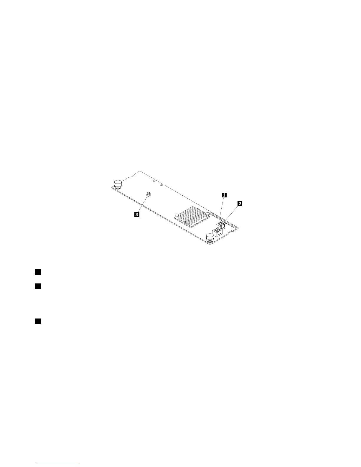
LenovoThinkServerRAID510iAnyRAIDAdapter
ThefollowingillustrationshowstheconnectorsontheLenovoThinkServerRAID510iAnyRAIDAdapter.
Figure15.LenovoThinkServerRAID510iAnyRAIDAdapter
1PCIE0connector
2PCIE1connector
UsedtoconnecttotheAnyRAIDconnector0–1onthesystemboard.See“Systemboardcomponents”
onpage43.
3RAIDupgradekeyconnector
UsedtoconnectaThinkServerRAID510iupgradekey.
32ThinkServerRD650UserGuideandHardwareMaintenanceManual
Page 47
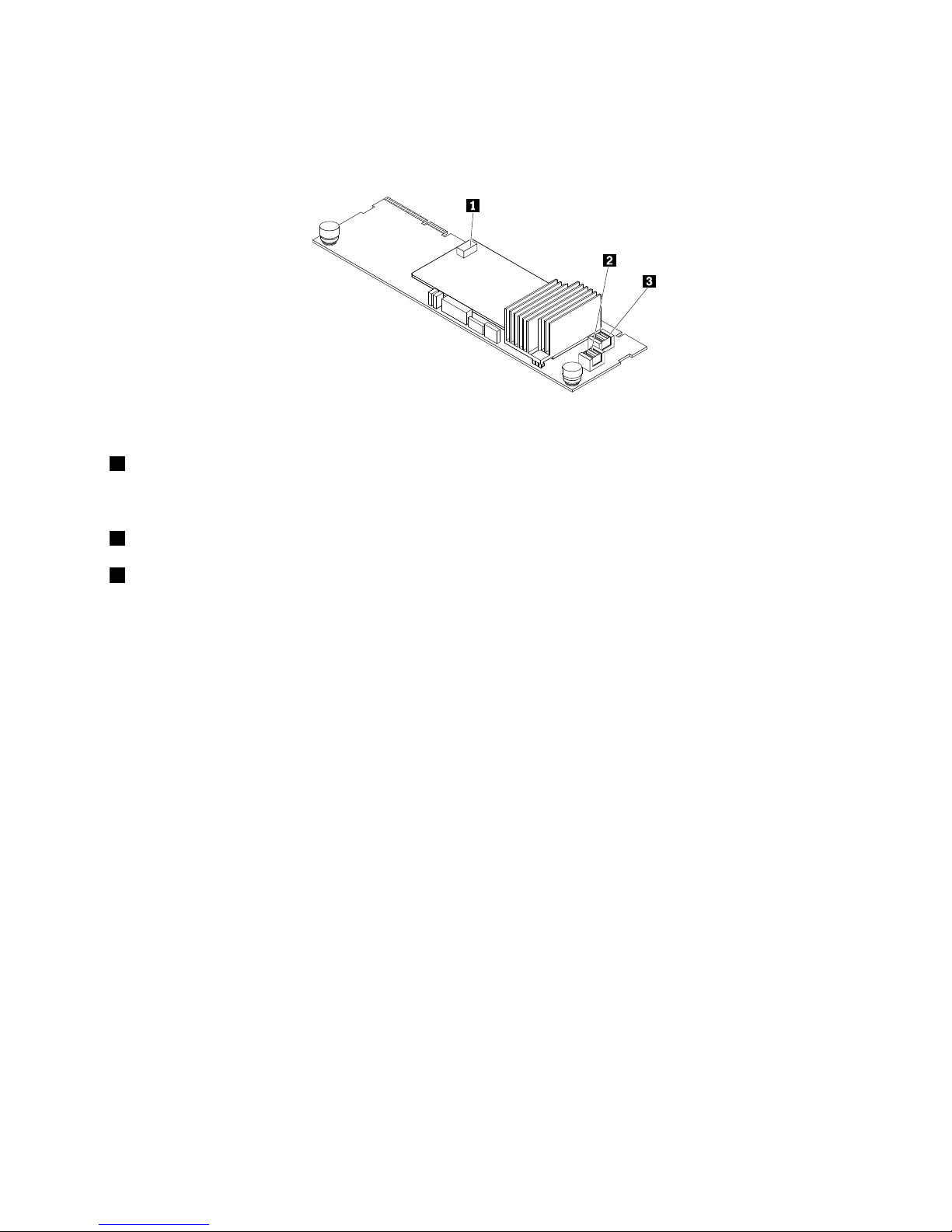
LenovoThinkServerRAID720iAnyRAIDAdapter
ThefollowingillustrationshowstheconnectorsontheLenovoThinkServerRAID720iAnyRAIDAdapter.
Figure16.ThinkServerRAID720iAnyRAIDAdapter
1ThinkServerRAIDSuperCapacitorModuleconnector(availableonsomemodels)
UsedtoconnecttotheThinkServerRAIDSuperCapacitorModule.See“Servercomponents”onpage28
.
2PCIE0connector
3PCIE1connector
UsedtoconnecttotheAnyRAIDconnector0–1onthesystemboard.See“Systemboardcomponents”
onpage43
.
Chapter3.Productoverview33
Page 48
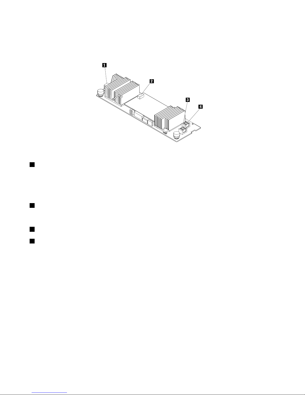
ThinkServerRAID720ixAnyRAIDAdapter
ThefollowingillustrationshowstheconnectorsontheThinkServerRAID720ixAnyRAIDAdapter.
Figure17.ThinkServerRAID720ixAnyRAIDAdapter
1SATAconnector
UsedtoconnecttheSATAsignalcablefromanyofthefollowingcomponent:
•Rearbackplaneforuptotwo2.5-inchdrives(availableonsomemodels)
•Internaltapedrive(availableonsomemodels)
2ThinkServerRAIDSuperCapacitorModuleconnector
UsedtoconnecttotheThinkServerRAIDSuperCapacitorModule.See“Servercomponents”onpage28
.
3PCIE0connector
4PCIE1connector
UsedtoconnecttotheAnyRAIDconnector0–1onthesystemboard.See“Systemboardcomponents”
onpage43.
34ThinkServerRD650UserGuideandHardwareMaintenanceManual
Page 49
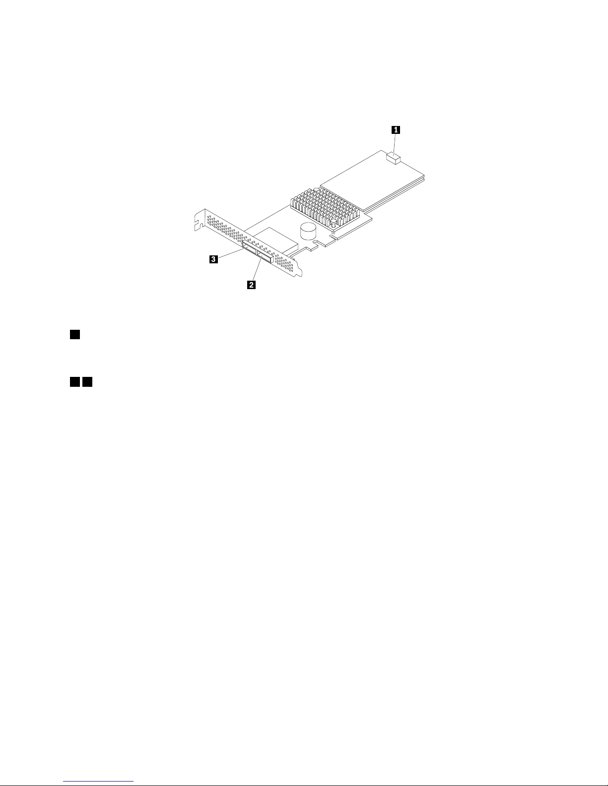
LenovoThinkServer9286RAIDAdapter
ThefollowingillustrationshowstheconnectorsontheLenovoThinkServer9286RAIDAdapter.
Figure18.LenovoThinkServer9286RAIDAdapter
1ThinkServerRAIDSuperCapacitorModuleconnector
UsedtoconnecttotheThinkServerRAIDSuperCapacitorModule.See“Servercomponents”onpage28
.
23SASconnector
Usedtoconnectexternalstoragedevices.
Chapter3.Productoverview35
Page 50
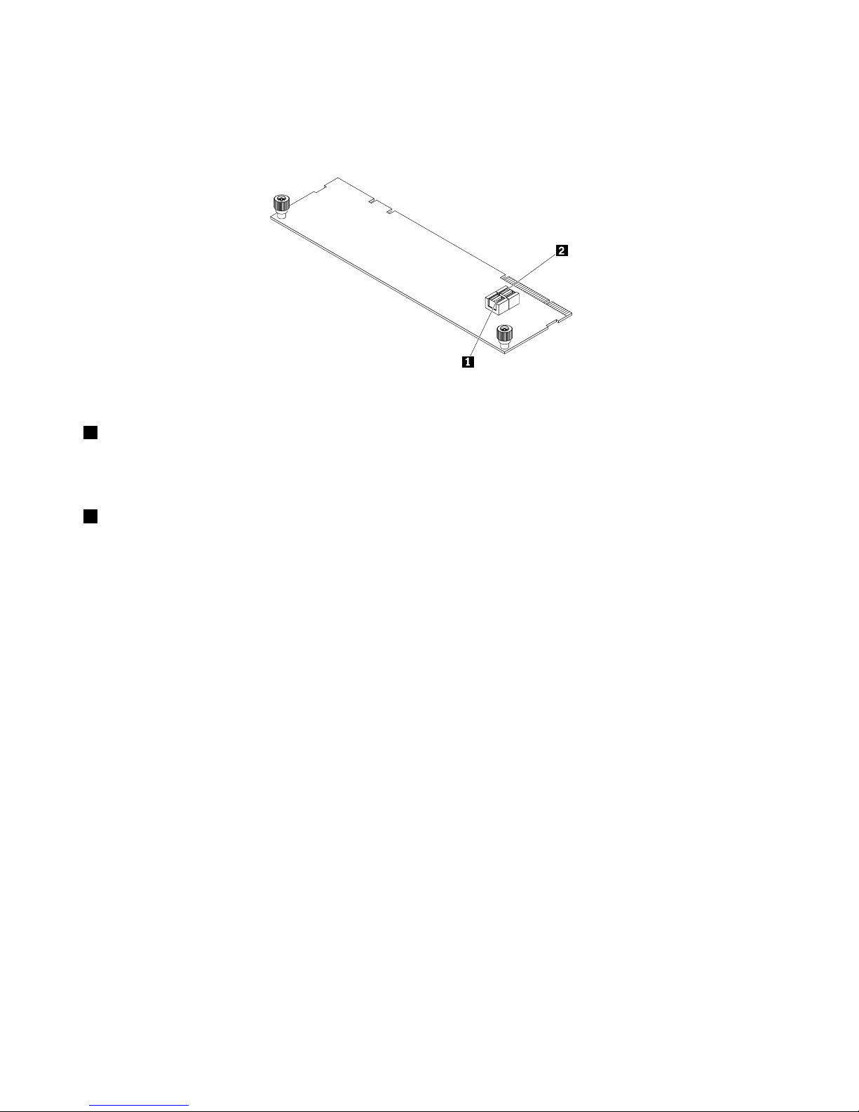
LenovoThinkServerRAID110ipass-throughboard
ThefollowingillustrationshowstheconnectorsontheLenovoThinkServerRAID110ipass-throughboard.
Figure19.LenovoThinkServerRAID110ipass-throughboard
1SATA0–3connector
UsedtoconnecttotheSATAconnector0(ports0–3)onthesystemboard.See“Systemboardcomponents”
onpage43.
2SATA4–7connector
UsedtoconnecttotheSATAconnector1(ports4–7)onthesystemboard.See“Systemboardcomponents”
onpage43.
Hot-swap-drivebackplane
Yourservercomeswithoneofthefollowingdrivebayandbackplaneconfigurations:
36ThinkServerRD650UserGuideandHardwareMaintenanceManual
Page 51

•Inthefront:
DrivebaysizeDrivebayquantityBackplanequantityDrivetype
3.5-inch121
Hot-swap,SATAorSAS
3.5-inchharddiskdriveor
2.5-inchsolid-statedrive
2.5-inch81
Hot-swap,SATAorSAS
Harddiskdriveorsolid-state
drive
2.5-inch162
Hot-swap,SATAorSAS
Harddiskdriveorsolid-state
drive
2.5-inch242
Hot-swap,SATAorSAS
Harddiskdriveorsolid-state
drive
2.5-inch/3.5-inchmixed
6(2.5-inch)
9(3.5-inch)
1(for2.5-inchdrives)
1(for3.5-inchdrives)
Hot-swap,SATAorSAS
Harddiskdrive(3.5-inch)
Harddiskdriveorsolid-state
drive(2.5-inch)
•Intherear:
DrivebaysizeDrivebayquantityBackplanequantityDrivetype
2.5-inch21
Hot-swap,SATA
Harddiskdriveorsolid-state
drive
Tolocatethebackplanes,see“Servercomponents”onpage28.
Chapter3.Productoverview37
Page 52
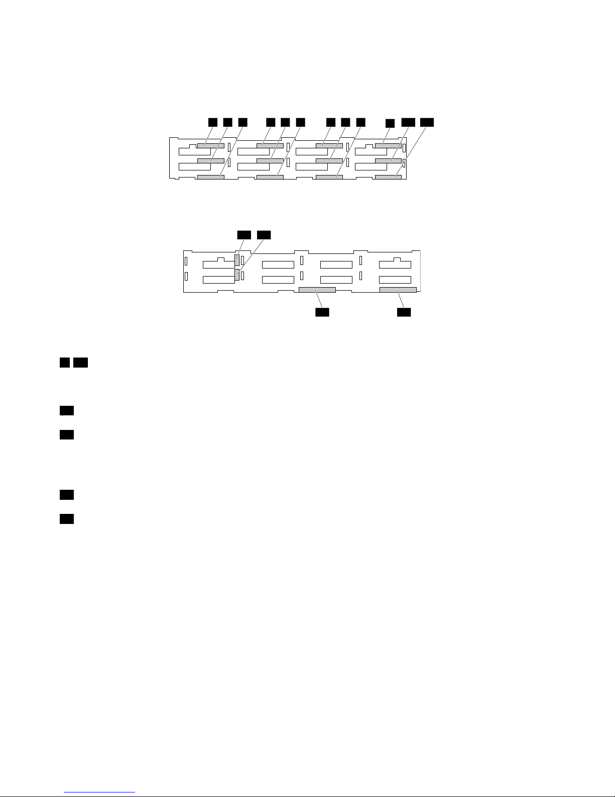
Backplaneforuptotwelve3.5-inchdrives
Thefollowingillustrationsshowtheslotsandconnectorsonthebackplaneforuptotwelve3.5-inchdrives.
0 1 2 3 4 5 6 7 8
9
10 11
Figure20.Frontviewofthebackplaneforuptotwelve3.5-inchdrives
12 13
1415
Figure21.Rearviewofthebackplaneforuptotwelve3.5-inchdrives
0–11Slot0–slot11
Usedtoconnect3.5-inchdrives.
1210-pinpowerconnector0
1310-pinpowerconnector1
Usedtoconnecttothe10-pinbackplanepowerconnectoronthesystemboardoronthepowerdistribution
boardtoprovidepowertothebackplane.
14AnyRAIDadapterslot0
15AnyRAIDadapterslot1
UsedtoconnectanAnyRAIDadapter.
38ThinkServerRD650UserGuideandHardwareMaintenanceManual
Page 53
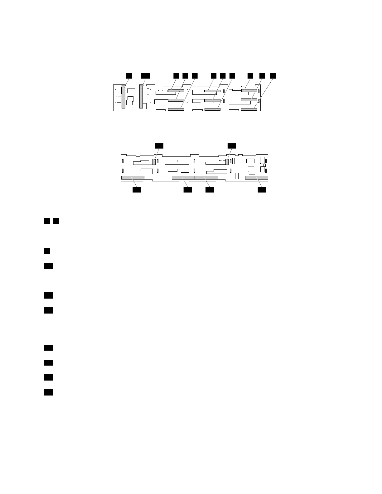
Backplaneforuptonine3.5-inchdrives
Thefollowingillustrationsshowtheslotsandconnectorsonthebackplaneforuptonine3.5-inchdrives.
0 1 2 3 4 5 6 7 8109
Figure22.Frontviewofthebackplaneforuptonine3.5-inchdrives
11 12
13141516
Figure23.Rearviewofthebackplaneforuptonine3.5-inchdrives
0–8Slot0–slot8
Usedtoconnect3.5-inchdrives.
9AnyRAIDadapterslot4
10AnyRAIDadapterslot5
Usedtoconnectaninterposercard.
1110-pinpowerconnector0
1210-pinpowerconnector1
Usedtoconnecttothe10-pinbackplanepowerconnectoronthesystemboardoronthepowerdistribution
boardtoprovidepowertothebackplane.
13AnyRAIDadapterslot0
14AnyRAIDadapterslot1
15AnyRAIDadapterslot2
16AnyRAIDadapterslot3
UsedtoconnectanAnyRAIDadapter.
Chapter3.Productoverview39
Page 54
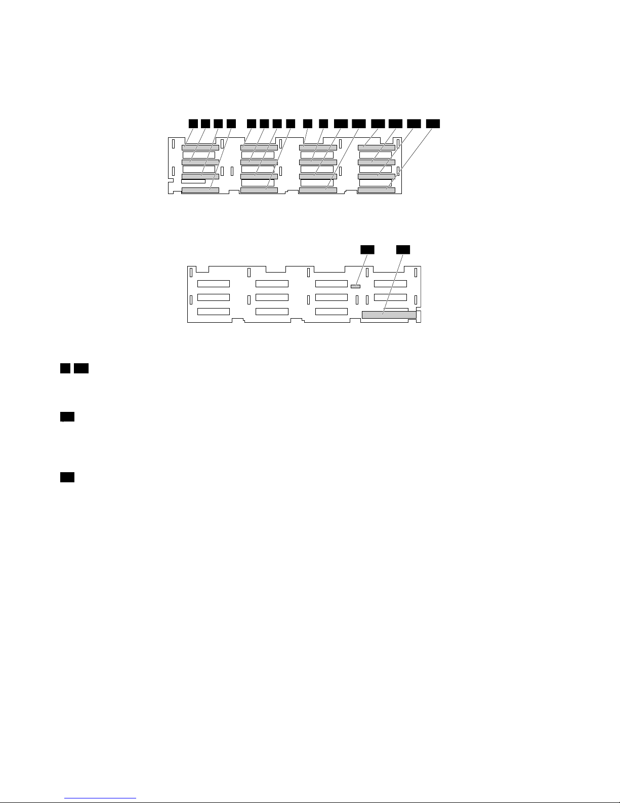
Backplaneforuptosixteen2.5-inchdrives
Thefollowingillustrationsshowtheslotsandconnectorsonthebackplaneforuptosixteen2.5-inchdrives.
0 1 2 3 4 5 6 7 8 9 1210 11 13 14 15
Figure24.Frontviewofthebackplaneforuptosixteen2.5-inchdrives
16 17
Figure25.Rearviewofthebackplaneforuptosixteen2.5-inchdrives
0–15Slot0–slot15
Usedtoconnect2.5-inchdrives.
1610-pinpowerconnector0
Usedtoconnecttothe10-pinbackplanepowerconnectoronthesystemboardoronthepowerdistribution
boardtoprovidepowertothebackplane.
17AnyRAIDadapterslot0
UsedtoconnectanAnyRAIDadapter.
40ThinkServerRD650UserGuideandHardwareMaintenanceManual
Page 55
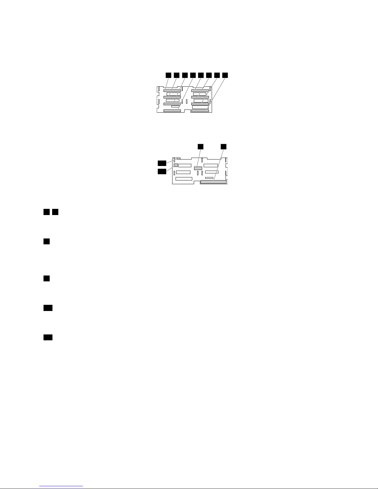
Backplaneforuptoeight2.5-inchdrives
Thefollowingillustrationsshowtheslotsandconnectorsonthebackplaneforuptoeight2.5-inchdrives.
0 1 2 3 4 5 6 7
Figure26.Frontviewofthebackplaneforuptoeight2.5-inchdrives
8 9
10
11
Figure27.Rearviewofthebackplaneforuptoeight2.5-inchdrives
0–7Slot0–slot7
Usedtoconnect2.5-inchdrives.
810-pinpowerconnector0
Usedtoconnecttothe10-pinbackplanepowerconnectoronthesystemboardoronthepowerdistribution
boardtoprovidepowertothebackplane.
9AnyRAIDadapterslot0
UsedtoconnectanAnyRAIDadapter.
104-pinpowerconnector
Usedtoconnecttoaninternaltapedriveiftheserverhasoneinstalled.
112-pinpowerconnector
Usedtoconnecttoanopticaldriveiftheserverhasoneinstalled.
Chapter3.Productoverview41
Page 56
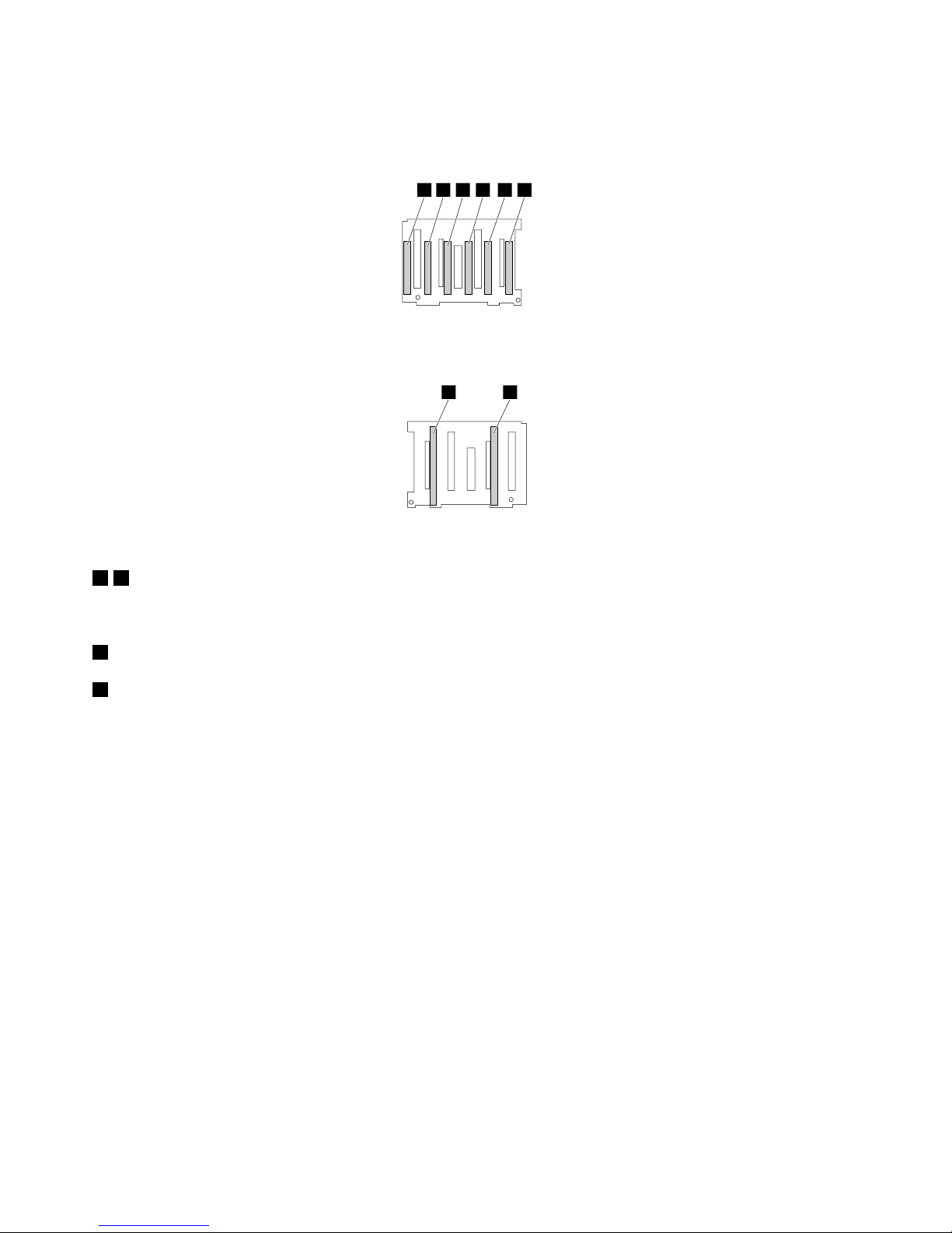
Backplaneforuptosix2.5-inchdrives
Thefollowingillustrationsshowtheslotsandconnectorsonthebackplaneforuptosix2.5-inchdrives.
0 1 2 3 4 5
Figure28.Frontviewofthebackplaneforuptosix2.5-inchdrives
6 7
Figure29.Rearviewofthebackplaneforuptosix2.5-inchdrives
0–5Slot0–slot5
Usedtoconnect2.5-inchdrives.
6AnyRAIDadapterslot1
7AnyRAIDadapterslot0
Usedtoconnectaninterposercard.
42ThinkServerRD650UserGuideandHardwareMaintenanceManual
Page 57
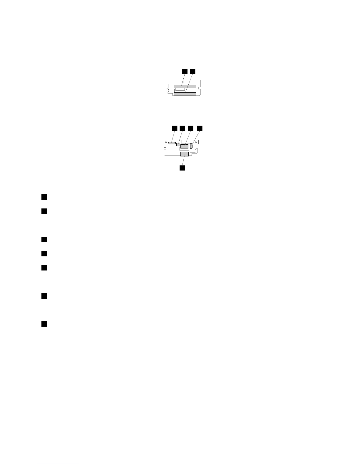
Rearbackplaneforuptotwo2.5-inchdrives
Thefollowingillustrationsshowtheslotsandconnectorsontherearbackplaneforuptotwo2.5-inchdrives.
0 1
Figure30.Frontviewoftherearbackplaneforuptotwo2.5-inchdrives
2 3 4 5
6
Figure31.Rearviewoftherearbackplaneforuptotwo2.5-inchdrives
0Slot0
1Slot1
Usedtoconnect2.5-inchdrives.
2Drivesidebandsignalsconnector
4Driveconnector0
6Driveconnector1
UsedtoconnecttotheSATAconnectorontheLenovoThinkServerRAID720ixAnyRAIDAdapter.
34-pinpowerconnector
Usedtoconnecttotherear-backplanepowerconnectoronthesystemboard.
5Rear-backplanesignalconnector
Usedtoconnecttotherear-backplanesignalconnectoronthesystemboard.
Systemboardcomponents
Thefollowingillustrationshowsthecomponentlocationsonthesystemboard.
Chapter3.Productoverview43
Page 58
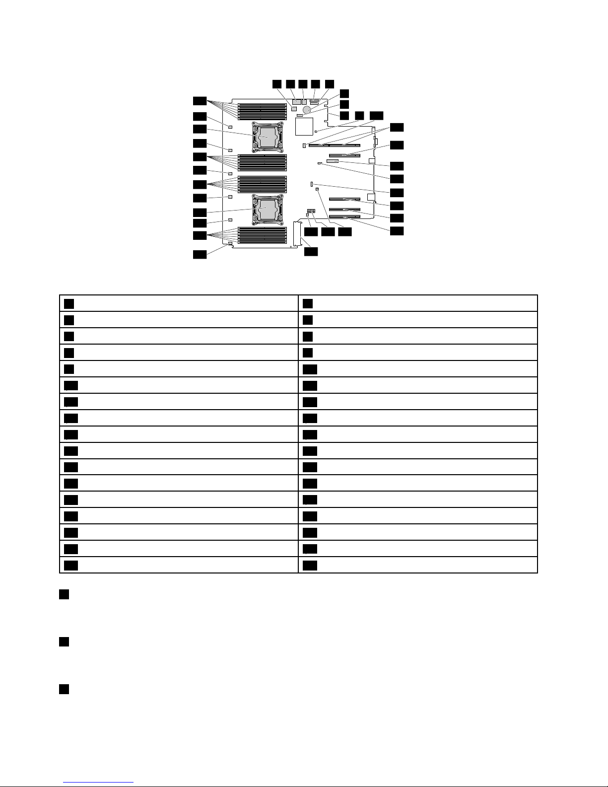
1 2 3 4 5
6
7
8 9 10
11
12
13
14
15
16
17
18
23
25
27
29
31
33
32
26
24
28
30
34
192021
22
Figure32.Systemboardcomponents
1SATAconnector1(ports4-7)
2AnyRAIDconnector0-1
3SATAconnector0(ports0-3)
4Frontpanelconnector2
5Frontpanelconnector1
6Coin-cellbattery
7SATAconnector(opticaldrive)
8AnyFabricconnector
9RAIDupgradekeyconnector
10SDmoduleconnector
11Risercardassembly1slot
12PCIeslot4
13TPMconnector
14TSMconnector
15Rear-backplanesignalconnector16Risercardassembly2slot
17PCIeslot718PCIeslot8
19Rear-backplanepowerconnector20Front-backplanepowerconnector
21Intrusionswitchconnector22Power-distribution-boardconnector
23Systemfan6connector24Microprocessor2memoryslots(6)
25Systemfan5connector
26Microprocessor2socket
27Systemfan4connector28Microprocessor2memoryslots(6)
29Systemfan3connector30Microprocessor1memoryslots(6)
31Systemfan2connector
32Microprocessor1socket
33Systemfan1connector34Microprocessor1memoryslots(6)
1SATAconnector1(ports4-7)
UsedtoconnecttotheSATA4–7connectorontheThinkServerRAID110ipass-throughboard.
2AnyRAIDconnector0-1
UsedtoconnecttothePCIeconnectorsontheAnyRAIDadapter.
3SATAconnector0(ports0-3)
UsedtoconnecttotheSATA0–3connectorontheThinkServerRAID110ipass-throughboard.
44ThinkServerRD650UserGuideandHardwareMaintenanceManual
Page 59
45Frontpanelconnector
Usedtoconnecttothefrontpanelboard.However,frontpanelconnector2(4)canbeconnectedonlyto
thefrontpanelboardthathastwoUSBconnectorsandoneDisplayPortconnector.
6Coin-cellbattery
Yourserverhasaspecialtypeofmemorythatmaintainsthedate,time,andconfigurationinformationfor
built-infeatures.Thecoin-cellbatterykeepstheinformationactivewhenyouturnofftheserver.
7SATAconnector(opticaldrive)
Usedtoconnectthesignalcableoftheslimopticaldrive.
8AnyFabricconnector
UsedtoconnecttheAnyFabricadapter.
9RAIDupgradekeyconnector
UsedtoconnectaThinkServerRAID110iupgradekey.
10SDmoduleconnector
UsedtoconnectanSDmodule.
11Risercardassembly1slot
Usedtoinstalltherisercardassembly1.
12PCIeslot4
17PCIeslot7
18PCIeslot8
UsedtoinstallasupportedPCIecard.ForinformationaboutsupportedPCIecards,see“Rearviewof
theserver”onpage25.
13TPMconnector
UsedtoconnectaTPM.TPMisasecuritychipthatisusedtoenhanceserversecurity.
14TSMPremiumconnector
UsedtoconnectaTSMPremiumtoenableadvancedremotemanagementfunctionsonyourserver.
15Rear-backplanesignalconnector
Usedtoconnectthesignalcablefromtherearbackplaneforuptotwo2.5-inchdrives(availableonsome
models).
16Risercardassembly2slot
Usedtoinstalltherisercardassembly2.
Chapter3.Productoverview45
Page 60
19Rear-backplanepowerconnector
Usedtoconnecttothe4-pinpowerconnectorontherearbackplane.
20Front-backplanepowerconnector
Usedtoconnecttothe10-pinpowerconnectoronthefrontbackplane.
21Intrusionswitchconnector
Usedtoconnecttoanintrusionswitch.
22Power-distribution-boardconnector
Usedtoconnectthepowerdistributionboard.
232527293133Systemfanconnector
Usedtoconnectasystemfan.
24283034Memoryslots
Thereare24memoryslotsonthesystemboard.Fordetailedinformation,see“Memorymoduleinstallation
rules”onpage79.
26Microprocessor2socket
32Microprocessor1socket
Iftheserverhastwomicroprocessors,eachofthemicroprocessorissecuredinthemicroprocessorsocket
onthesystemboardandaheatsinkisinstalledabovethemicroprocessortoprovidecooling.Iftheserver
hasonlyonemicroprocessor,themicroprocessorsocket2isprotectedbyamicroprocessorsocketcover.
46ThinkServerRD650UserGuideandHardwareMaintenanceManual
Page 61
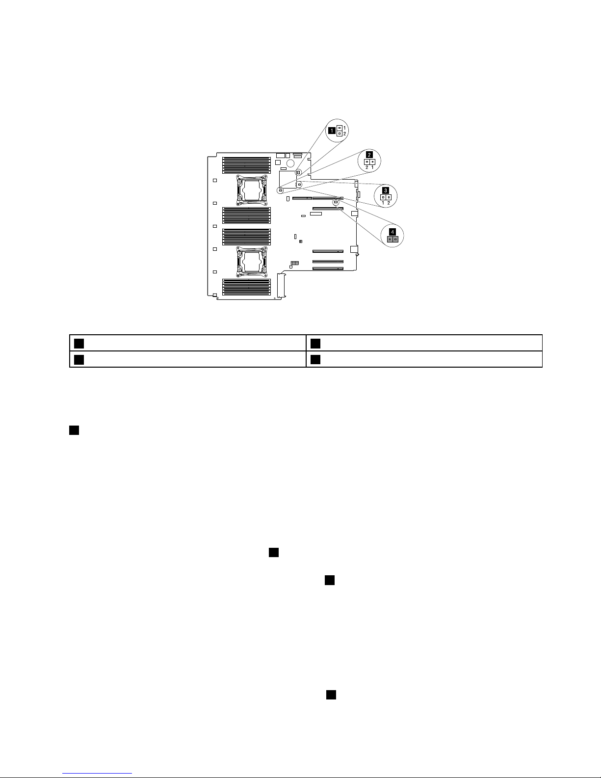
Systemboardjumpers
Thefollowingillustrationshowsthejumpersonthesystemboardofyourserver.
1
3
4
2
1
2
2 1
1 2
Figure33.Systemboardjumpers
1BIOSdefaultsettingsjumper2Clearpasswordjumper
3BIOSrecoveryjumper
4Jumpercapstorage
Attention:Tosetthejumpers,removetheservercoverandgainaccesstothesystemboardfirst.Donot
openyourserverorattemptanyrepairbeforereadingandunderstanding“Safetyinformation”onpageiii
and“Guidelines”onpage67.
1BIOSdefaultsettingsjumper
UsedtoturntheBIOSsettingsintothefactorydefaultsettings.
ToturntheBIOSsettingsintothefactory-defaultsettings,dothefollowing:
1.Removeallmediafromthedrivesandturnoffallattacheddevicesandtheserver.Then,disconnectall
powercordsfromelectricaloutletsanddisconnectallcablesthatareconnectedtotheserver.
2.Prepareyourserver.See“Removingorextendingtheserverfromtherackcabinet”onpage69.
3.Removetheservercover.See“Removingtheservercover”onpage69.
4.LocatetheBIOSdefaultsettingsjumper1onthesystemboard.Then,removeanypartsand
disconnectanycablesthatmightimpedeyouraccesstothejumper.
5.Removethejumpercapfromthejumpercapstorage4.
6.NotetheorientationofthejumpercapandtheninstallthejumpercapontheBIOSdefaultsettings
jumper.
7.Reinstallanypartsandreconnectanycables.Then,reinstalltheservercover.See“Completingthe
partsreplacement”onpage183.
8.Connecttheservertoanacpowersourceandwaitforseveralminutes.Then,turnontheserver.The
BIOSsettingsturnintothefactory-defaultsettings.
9.Repeatstep1throughstep3.
10.Movethejumpercapbacktothejumpercapstorage4.
Chapter3.Productoverview47
Page 62
11.Reinstallanypartsandreconnectanycables.Then,reinstalltheservercover.See“Completingthe
partsreplacement”onpage183
.
12.Connecttheservertoanacpowersourceandturnontheserver.
2Clearpasswordjumper
Usedtoeraseforgottenpasswords,suchastheBIOSpasswords.
Toclearpasswords,dothefollowing:
1.Removeallmediafromthedrivesandturnoffallattacheddevicesandtheserver.Then,disconnectall
powercordsfromelectricaloutletsanddisconnectallcablesthatareconnectedtotheserver.
2.Prepareyourserver.See“Removingorextendingtheserverfromtherackcabinet”onpage69.
3.Removetheservercover.See“Removingtheservercover”onpage69.
4.Locatetheclearpasswordjumper2onthesystemboard.Then,removeanypartsanddisconnectany
cablesthatmightimpedeyouraccesstothejumper.
5.Removethejumpercapfromthejumpercapstorage4.
6.Notetheorientationofthejumpercapandtheninstallthejumpercapontheclearpasswordjumper.
7.Reinstallanypartsandreconnectanycables.Then,reinstalltheservercover.See“Completingthe
partsreplacement”onpage183.
8.Connecttheservertoanacpowersourceandwaitforseveralminutes.Then,turnontheserver.The
BIOSpasswordsareerased,includingtheadministratorpasswordanduserpassword.
9.Repeatstep1throughstep3.
10.Movethejumpercapbacktothejumpercapstorage4.
11.Reinstallanypartsandreconnectanycables.Then,reinstalltheservercover.See“Completingthe
partsreplacement”onpage183
.
12.Connecttheservertoanacpowersourceandturnontheserver.
13.Tosetnewpasswords,see“Usingpasswords”onpage58.
3BIOSrecoveryjumper
UsedtorecovertheBIOSifthepowertoyourserverisinterruptedwhiletheBIOSisbeingupdatedandyour
servercannotstartcorrectly.
TorecovertheBIOS,see“RecoveringfromaBIOSupdatefailure”onpage61.
4Jumpercapstorage
Usedtostorethejumpercap.Ajumpercapisencasedonthepinsbydefault.
48ThinkServerRD650UserGuideandHardwareMaintenanceManual
Page 63
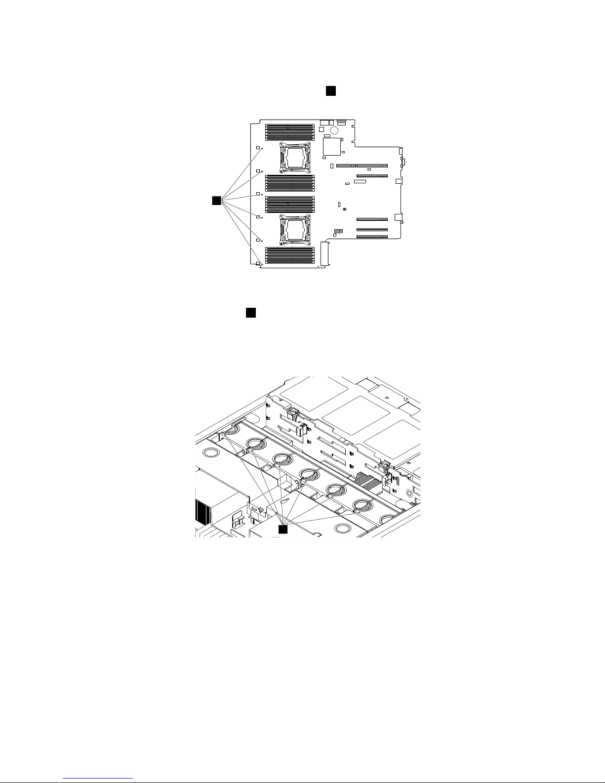
SystemfanfaultLEDs
ThefollowingillustrationshowsthesystemfanfaultLEDs1onthesystemboard.
1
Figure34.SystemfanfaultLEDs
YoucanviewthesystemfanfaultLEDs
1fromthetopofthesystemfans.WhenasystemfanfaultLEDis
lit,itindicatesthatthecorrespondingsystemfanisoperatingslowlyorhasfailed.Tosolvetheproblem,
reinstallorreplacethesystemfan.See“Installingorreplacingasystemfan”onpage74
.Ifitisasystem
boardproblem,contacttheLenovoCustomerSupportCenter.
1
Figure35.ViewingthesystemfanfaultLEDsfromthetopofthesystemfans
Chapter3.Productoverview49
Page 64
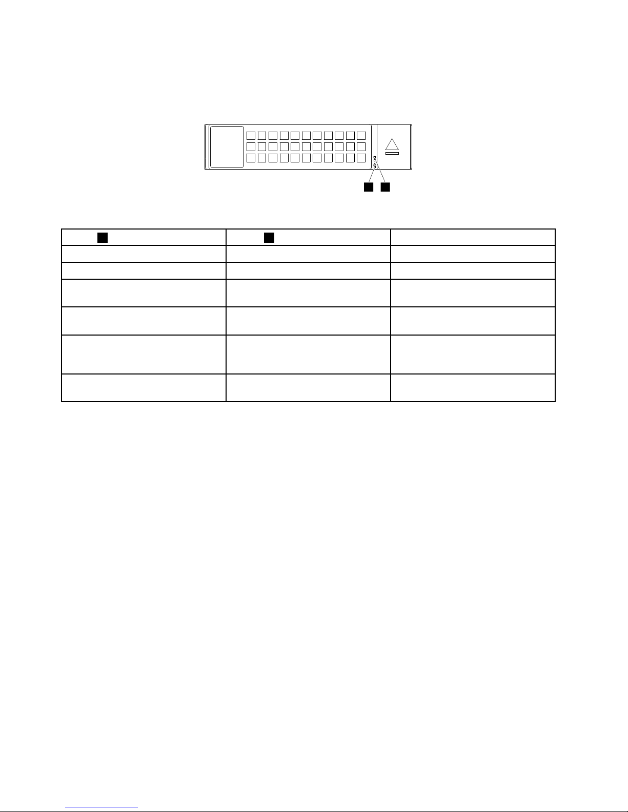
Hot-swap-drivestatusLEDs
Eachhot-swapdrivehastwostatusLEDsonthefront.
12
Figure36.Hot-swap-drivestatusLEDs
1DriveactivityLED2DrivestatusLEDDescription
OffOff
Thedrivehasfailedorisnotpresent.
On,greenOff
Thedriveispresentbutnotinuse.
Blinking,green
Off
Thedriveisactiveanddataisbeing
transferred.
On,greenBlinkingrapidly(aboutfourflashes
persecond),amber
TheRAIDcontrollerisidentifyingthe
drive.
On,greenOn,amber
TheRAIDarrayhasfailedandcannot
berecovered.Youneedtorecreatea
newarray.
Blinking,green
Blinkingslowly(aboutoneflashper
second),amber
Thedriveisbeingrebuilt.
50ThinkServerRD650UserGuideandHardwareMaintenanceManual
Page 65
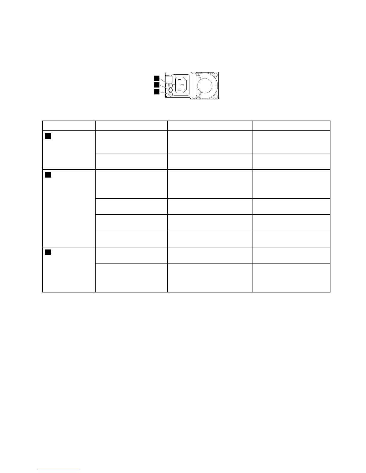
PowersupplystatusLEDs
Eachhot-swappowersupplyhasthreestatusLEDs.
1
2
3
Figure37.PowersupplystatusLEDs
LED
Status
DescriptionAction
Off
Thepowersupplyis
disconnectedfromtheac
powersource.
Noactionisneeded.
1InputstatusLED
On,green
Thepowersupplyisconnected
totheacpowersource.
Noactionisneeded.
Off
Theserverisofforthepower
supplyisnotworkingnormally.
Replacethepowersupply.
See“Installingorreplacinga
hot-swapredundantpower
supply”onpage119
.
Blinking,green(aboutone
flasheverytwoseconds)
Thepowersupplyisincold
redundancyactivemode.
Noactionisneeded.
Blinking,green(abouttwo
flasheseachsecond)
Thepowersupplyisincold
redundancysleepmode.
Noactionisneeded.
2Outputstatus
LED
On,green
Theserverisonandthepower
supplyisworkingnormally.
Noactionisneeded.
Off
Thepowersupplyisworking
normally.
Noactionisneeded. 3FaultLED
On,amber
Thepowersupplyhasfailed.
Replacethepowersupply.
See“Installingorreplacinga
hot-swapredundantpower
supply”onpage119
.
Connectingcables
Toconnectthesignalcablesfromtheinstalledhardwarecomponents,refertotherelatedinformation
inthefollowingtopics:
•“Systemboardcomponents”onpage43
•“AnyRAIDadapter,RAIDcard,andpass-throughboard”onpage31
•“Hot-swap-drivebackplane”onpage36
•“Installingthetapedrive”onpage167
Chapter3.Productoverview51
Page 66

52ThinkServerRD650UserGuideandHardwareMaintenanceManual
Page 67
Chapter4.Turningonandturningofftheserver
Thischapterprovidesinformationaboutturningonandturningofftheserver.
Turningontheserver
Theservercanbeturnedoninoneofthefollowingways:
•Afteryoufinishunpackingandsettinguptheserver,connectittoanacpowersource.Pressthepower
buttononthefrontpaneltoturnontheserver.See“Frontpanel”onpage23
.Theserverneedsabout
30secondsfortheThinkServerSystemManager(TSM,alsoknownasBMC)toinitializewheneveryou
connecttheservertoanacpowersource.Ifyoupressthepowerbuttononthefrontpanelduringthis
period,theserverwillnotstartimmediately;itwillstartaftertheTSMinitializationfinishes.
•WhentheWakeonLANfeatureisenabledontheserverthatisconnectedtoanacpowersourceanda
LAN,anetworkadministratorcanremotelyturnonorwakeuptheserverfromamanagementconsole
usingremotenetworkmanagementsoftware.
•YoualsocanusetherelatedTSMfeaturetoremotelyturnontheserverthroughthemanagementLAN.
Turningofftheserver
CAUTION:
Thepowercontrolbuttononthedeviceandthepowerbuttononthepowersupplydonotturnoff
theelectricalcurrentsuppliedtothedevice.Thedevicealsomighthavemorethanonepower
cord.T oremoveallelectricalcurrentfromthedevice,ensurethatallpowercordsaredisconnected
fromthepowersource.
Theservercanbeturnedoffinoneofthefollowingways:
•Turnofftheserverfromtheoperatingsystemifyouroperatingsystemsupportsthisfeature.Afteran
orderlyshutdownoftheoperatingsystem,theserverwillturnoffautomatically.Forinstructionsonhow
toshutdownyourspecificoperatingsystem,refertotherelateddocumentationorhelpsystemfor
theoperatingsystem.
•Pressthepowerbuttononthefrontpaneltostartanorderlyshutdownoftheoperatingsystemandturn
offtheserver,ifyouroperatingsystemsupportsthisfeature.
•Ifyourserverstopsrespondingandyoucannotturnitoff,pressandholdthepowerbuttononthe
frontpanelforfoursecondsormore.Ifyoustillcannotturnofftheserver,disconnectallpowercords
fromtheserver.
•IftheserverisconnectedtoaLAN,anetworkadministratorcanremotelyturnofftheserverfroma
managementconsoleusingremotenetworkmanagementsoftware.
•YoualsocanusetherelatedTSMfeaturetoremotelyturnofftheserverthroughthemanagementLAN.
•Theservermightbeturnedoffasanautomaticresponsetoacriticalsystemfailure.
Notes:
•Whenyouturnofftheserverandleaveitconnectedtoanacpowersource,theserveralsocanrespond
toaremoterequesttoturnontheserver.Toremoveallpowerfromtheserver,youmustdisconnect
theserverfromtheacpowersource.
©CopyrightLenovo2014
53
Page 68

•Forinformationaboutyourspecificoperatingsystem,refertotherelateddocumentationorhelpsystem
fortheoperatingsystem.
54ThinkServerRD650UserGuideandHardwareMaintenanceManual
Page 69

Chapter5.Configuringtheserver
Thischapterprovidesthefollowinginformationtohelpyouconfiguretheserver:
•“UsingtheSetupUtilityprogram”onpage55
•“ConfiguringRAID”onpage62
•“Updatingthefirmware”onpage65
UsingtheSetupUtilityprogram
TheSetupUtilityprogramispartoftheserverfirmware.Y oucanusetheSetupUtilityprogramtoviewand
changetheconfigurationsettingsofyourserver,regardlessofwhichoperatingsystemyouareusing.
However,theoperatingsystemsettingsmightoverrideanysimilarsettingsintheSetupUtilityprogram.
StartingtheSetupUtilityprogram
TostarttheSetupUtilityprogram,dothefollowing:
1.Connecttheservertoanacpowersourceandpressthepowerbuttononthefrontpaneltoturnonthe
server.See“T urningontheserver”onpage53
.
2.PresstheF1keyassoonasyouseethelogoscreen.Then,waitforseveralseconds,andtheSetup
Utilityprogramopens.Ifyouhavesetapassword,typethecorrectpasswordtoentertheSetupUtility
program.Forpasswordinformation,see“Usingpasswords”onpage58
.
ViewinginformationintheSetupUtilityprogram
TheSetupUtilityprogrammenulistsvariousitemsaboutthesystemconfiguration.Selectadesireditem
toviewinformationorchangesettings.
WhenworkingwiththeSetupUtilityprogram,youmustusethekeyboard.Thekeysusedtoperformvarious
tasksaredisplayedontherightbottompaneofeachscreen.YoualsocanpresstheF1keyforgeneralhelp
aboutthekeys.Formostitems,thecorrespondinghelpmessageisdisplayedontherighttoppaneofthe
screenwhentheitemisselected.Iftheitemhassubmenus,youcandisplaythesubmenusbypressingEnter.
SetupUtilityprograminterface
DependingontheBIOSversionofyourserver,somemenuoriteminformationmightdifferslightlyfrom
theinformationinthistopic.
Notes:
•Thedefaultsettingsalreadyareoptimizedforyou.Usethedefaultvalueforanyitemyouarenotfamiliar
with.Donotchangethevalueofunfamiliaritemstoavoidunexpectedproblems.Ifyouconsider
changingtheserverconfiguration,proceedwithextremecaution.Settingtheconfigurationincorrectly
mightcauseunexpectedresults.IfyoucannotturnontheserverbecauseofincorrectBIOSsettings,
usetheBIOSdefaultsettingsjumpertorestoretheBIOSsettingstothefactorydefaultsettings.See
“Systemboardjumpers”onpage47
.
•Ifyouhavechangedanyhardwareintheserver,youmightneedtoreflashtheBIOSandtheTSMfirmware.
©CopyrightLenovo2014
55
Page 70

TheSetupUtilityprogrammaininterfaceconsistsofthefollowingmenus:
•“SystemInformationmenu”onpage56
•“AdvancedSettingsmenu”onpage56
•“SystemSecuritymenu”onpage57
•“TSMSettingsmenu”onpage57
•“BootManagermenu”onpage57
•“Save&Exitmenu”onpage57
LenovoprovidestheBIOSupdateutilityontheLenovoSupportWebsite.YoucandownloadtheBIOS
updateutilitytoupdatetheBIOS.See“UpdatingorrecoveringtheBIOS”onpage61
.Afterupdatingthe
BIOS,alltheBIOSsettingsbecomethedefaultsettingsoftheupdatedBIOSversion.Checkandreconfigure
theBIOSsettingsforyourspecificneeds.
IfthepowertoyourserverisinterruptedwhiletheBIOSisbeingupdatedandyourservercannotstart
correctly,usetheBIOSrecoveryjumpertorecoverfromaBIOSupdatefailure.See“Systemboardjumpers”
onpage47
.
SystemInformationmenu
AfterenteringtheSetupUtilityprogram,youcanseetheSystemInformationmenu.Themenulistsbasic
informationaboutyourserver,suchastheBIOS,microprocessortype,memory,andsystemdateandtime.
TosetthesystemdateandtimeontheSystemInformationmenu,see“Settingthesystemdateand
time”onpage58.
AdvancedSettingsmenu
YoucanvieworchangevariousservercomponentsettingsontheAdvancedSettingsmenuintheSetup
Utilityprogram.TheAdvancedSettingsmenucontainsvariousconfigurationsubmenusanditems.On
eachsubmenu,pressEntertoshowselectableoptionsandselectadesiredoptionbyusingtheupand
downarrowkeysortypedesiredvaluesfromthekeyboard.Someitemsaredisplayedonthemenuonlyif
theserversupportsthecorrespondingfeatures.
Notes:
•Enabledmeansthatthefunctionisconfigured.
•Disabledmeansthatthefunctionisnotconfigured.
TheAdvancedSettingsmenucontainsthefollowingsubmenus.Formoreinformation,enterthe
correspondingsubmenuandrefertotheinstructionsonthescreen.
•ProcessorSettings:Viewinformationabouttheinstalledmicroprocessorsandsetmicroprocessor
configurationparameters.
•MemorySettings:Viewinformationabouttheinstalledmemorymodulesandsetmemoryconfiguration
parameters.
•AdvancedPowerSettings:Viewandsetpowerparameters.
•PCI/PCIESettings:ViewandsetPCIorPCIeconfigurationparameters.
•SATASettings:SetonboardSATAparameters.
•USBSettings:ViewandsetUSBconfigurationparameters,suchasenablingordisablingUSBdevices.
•SerialSettings:Viewandsetconfigurationparametersfortheserialconnector.
•WakeupSettings:Viewandconfigurethewakeuptimingandsetthepowerstateafterapowerfailure.
56ThinkServerRD650UserGuideandHardwareMaintenanceManual
Page 71

•MiscellaneousSettings:Viewandconfiguresomemiscellaneousitems,suchastheNumLockkeyon
thekeyboardandthebootstatuscode.
SystemSecuritymenu
YoucansetpasswordsandconfiguretheTPMfunctionontheSystemSecuritymenuintheSetupUtility
program.Foreachmenuitem,pressEntertoshowselectableoptionsandselectadesiredoptionbyusing
theupanddownarrowkeysortypedesiredvaluesfromthekeyboard.Someitemsaredisplayedonthe
menuonlyiftheserversupportsthecorrespondingfeatures.
Notes:
•Enabledmeansthatthefunctionisconfigured.
•Disabledmeansthatthefunctionisnotconfigured.
TheSystemSecuritymenucontainsthefollowingitems:
•AdministratorPassword:Setanadministratorpasswordtoprotectagainstunauthorizedaccessto
yourserver.See“Usingpasswords”onpage58
.
•UserPassword:Setauserpasswordtoprotectagainstunauthorizedaccesstoyourserver.See“Using
passwords”onpage58.
•SecureBoot:Setsecurebootparameters.
•TPM/TCM:ConfiguretheTPMfunctionifyourserverhasaTPMinstalledintheTPMconnectoronthe
systemboard.See“ConfiguringtheTPMfunction”onpage60
.
TSMSettingsmenu
YoucanvieworchangeeventlogandBMCsettingsontheTSMSettingsmenuintheSetupUtilityprogram.
Oneachsubmenu,pressEntertoviewtheinformationorshowselectableoptionsandselectadesired
optionbyusingtheupanddownarrowkeys.Someitemsaredisplayedonthemenuonlyiftheserver
supportsthecorrespondingfeatures.
TheTSMSettingsmenucontainsthefollowingsubmenus.Formoreinformation,enterthecorresponding
submenuandrefertotheinstructionsonthescreen.
•TSMNetworkSettings:SetBMCmanagementnetworkconfigurationparameters.
•UserAccountSettings:SetBMCuseraccountparameters.
BootManagermenu
TheBootManagermenuintheSetupUtilityprogramlistsallthebootabledevicesinstalledinyourserver
andthelisteditemsvarydependingonyourserverconfiguration.
TheBootSequencesubmenuintheBootManagermenuprovidesaninterfacetohelpyouvieworchange
theserverstartupoptions,includingthestartupsequenceandbootpriorityforvariousdevices.Changesin
thestartupoptionstakeeffectwhentheserverstarts.Thestartupsequencespecifiestheorderinwhichthe
serverchecksdevicestofindabootrecord.Theserverstartsfromthefirstbootrecordthatitfinds.For
example,youcandefineastartupsequencethatchecksadiscintheopticaldrive,thencheckstheinternal
storagedrive,andthenchecksanetworkdevice.Forinformationaboutsettingthestartupsequenceor
selectingastartupdevice,see“Selectingastartupdevice”onpage59
.
Save&Exitmenu
AfteryoufinishviewingorchangingsettingsintheSetupUtilityprogram,youcanchooseadesired
actionfromtheSave&Exitmenutosavechanges,discardchanges,orloaddefaultvalues,andexitthe
program.PressEntertoselecttheitemontheSave&Exitmenu,andthenselectY eswhenpromptedto
confirmtheaction.ForinformationaboutexitingtheSetupUtilityprogram,see“ExitingtheSetupUtility
program”onpage60.
Chapter5.Configuringtheserver57
Page 72

TheSave&Exitmenucontainsthefollowingitems:
•SaveChangesandReset:SavechangesandthencontinuewithfurtherconfigurationintheSetup
Utilityprogram.
•DiscardChangesandExit:Discardchanges,loadpreviousvalues,andthenexittheSetupUtility
program.
•LoadOptimizedDefaults:Returntotheoptimizeddefaultsettings.
•SaveasUserDefaults:Savethecurrentsettingsasuserdefaultvalues.
•RestoreUserDefaults:Restoretheuserdefaultvaluesforalltheitems.
•PureUEFIOSOptimizedDefaults:EnableordisableoptimizeddefaultsettingsforthepureUEFI
operatingsystem.
Settingthesystemdateandtime
TosetthesystemdateandtimeintheSetupUtilityprogram,dothefollowing:
1.StarttheSetupUtilityprogram.See“StartingtheSetupUtilityprogram”onpage55.
2.OntheSystemInformationmenu,selectSystemDateorSystemTime.
3.UsetheTabkeytoswitchbetweendataelementsandtypethenumbersfromthekeyboardtosetthe
systemdateandtime.
4.PressF10tosavesettingsandexittheSetupUtilityprogram.
Usingpasswords
ByusingtheSetupUtilityprogram,youcansetapasswordtopreventunauthorizedaccesstoyourserver.
Youdonothavetosetapasswordtouseyourserver.However,usingapasswordimprovescomputing
security.Ifyoudecidetosetapassword,readthefollowingtopics.
SetupUtilityprogrampasswordtypes
ThefollowingtypesofpasswordsareavailableintheSetupUtilityprogram:
•Administratorpassword
Settinganadministratorpassworddetersunauthorizedusersfromchangingconfigurationsettings.Ifyou
areresponsibleformaintainingtheconfigurationsettingsofseveralcomputers,youmightwanttoset
anadministratorpassword.Whenanadministratorpasswordisset,youarepromptedtotypeavalid
passwordeachtimeyoutrytoaccesstheSetupUtilityprogram.TheSetupUtilityprogramcannot
beaccesseduntilavalidpasswordistypedin.
•Userpassword
Whenauserpasswordisset,theservercannotbeuseduntilavalidpasswordistypedin.
Note:Ifboththeadministratorpasswordanduserpasswordareset,youcantypeeitherpasswordtouse
theserver.However,youmustuseyouradministratorpasswordtochangeanyconfigurationsettings.
Passwordconsiderations
Forsecurityreasons,itisrecommendedtouseastrongpasswordthatcannotbeeasilycompromised.
Notes:
•TheSetupUtilityprogrampasswordsarenotcasesensitive.
•TheserversupportsSetupUtilityprogrampasswordsthatconsistofthreeto32characters.
Tosetastrongpassword,usethefollowingguidelines:
58ThinkServerRD650UserGuideandHardwareMaintenanceManual
Page 73

•Haveatleasteightcharactersinlength
•Containatleastonealphabeticcharacterandonenumericcharacter
•Notbeyournameoryourusername
•Notbeacommonwordoracommonname
•Besignificantlydifferentfromyourpreviouspasswords
Besidesthealphabeticcharacters(a–z)andnumericcharacters(0–9),theserveralsosupportscharacters
typedusingspecialkeysonthekeyboardforapassword.Refertothehelpmessageonthescreenwhen
settingapasswordtodeterminethevalidspecialcharacters.
Setting,changing,ordeletingapassword
Thistopicprovidesinstructionsonhowtoset,change,ordeleteapasswordintheSetupUtilityprogram.
Toset,change,ordeleteapasswordintheSetupUtilityprogram,dothefollowing:
1.StarttheSetupUtilityprogram.See“StartingtheSetupUtilityprogram”onpage55.
2.OntheSystemSecuritymenu,selectAdministratorPasswordtosetanadministratorpasswordor
selectUserPasswordtosetauserpassword.
3.See“Passwordconsiderations”onpage58.Then,followtheinstructionsonthescreentosetor
changeapassword.
4.Ifyouwanttodeleteapassword,typeyourcurrentpassword.PressEnterwhenyouareprompted
totypeanewpassword.Then,pressEntertoconfirmthenewpassword.Thepreviouspassword
willbecleared.
Note:Forsecurityreasons,itisrecommendedthatyoualwayssetapasswordforyourserver.
5.PressF10tosavesettingsandexittheSetupUtilityprogram.
Ifyouhaveforgottenthepassword,youcanusetheclearpasswordjumperonthesystemboardtoerase
thepassword.See“Systemboardjumpers”onpage47.Then,setanewpasswordfortheserver.
Selectingastartupdevice
Ifyourserverdoesnotstartupfromadesireddevicesuchasthediscorharddiskdriveasexpected,doone
ofthefollowingtoselectthestartupdeviceyouwant.
Note:Notalldiscs,harddiskdrives,orotherremovabledevicesarebootable.
•Toselectatemporarystartupdevice,dothefollowing:
Note:Selectingastartupdeviceusingthefollowingmethoddoesnotpermanentlychangethestartup
sequence.
1.Turnonorrestartyourserver.
2.Whenyouseethelogoscreen,pressF10ifyourserverisconnectedtoanetworkandyouwantto
startuptheserverfromthenetwork.Otherwise,pressF12todisplaythebootmenu.Theboot
deviceselectionwindowopens.
3.Inthebootdeviceselectionwindow,usetheupanddownarrowkeysonthekeyboardtoswitch
betweentheselections.PressEntertoselectthedeviceofyourchoice.Then,theserverwillstart
upfromtheselecteddevice.
•Tovieworpermanentlychangetheconfiguredstartupdevicesequence,dothefollowing:
1.StarttheSetupUtilityprogram.See“StartingtheSetupUtilityprogram”onpage55.
Chapter5.Configuringtheserver59
Page 74

2.OntheBootSequencesubmenuundertheBootManagermenu,followtheinstructionsonthe
screentosetthestartupdeviceforBootOption#1toBootOption#5dependingonyourneeds.
Youalsocansetthebootpriorityforvariousdevices.See“BootManagermenu”onpage57
.
3.PressF10tosavesettingsandexittheSetupUtilityprogram.Theserverwillfollowthestartupdevice
sequenceyouhaveseteachtimeyouturnontheserver.
ConfiguringtheTPMfunction
TheTPMworksasahardwaresecuritysolutiontohelpyoutoencryptdataandprotecttheserver.The
TPMfunctionisonlyavailablewhenthereisaTPMinstalledinyourserver.See“InstallingtheTPM”on
page114.YoucanpurchaseaTPMfromLenovo.
AfterinstallingaTPM,youneedtocheckiftheTPMfunctionisenabledintheSetupUtilityprogram.
ToenabletheTPMfunctionintheSetupUtilityprogram,dothefollowing:
1.StarttheSetupUtilityprogram.See“StartingtheSetupUtilityprogram”onpage55.
2.OntheSystemSecuritymenu,selectTPMSettings➙TPMSupport.EnsurethatTPMSupportis
settoEnabled.
3.WhenTPMSupportissettoEnabled,theTPMStateitemisdisplayed.SetTPMStatetoEnabled.
4.PressF10tosavesettingsandexittheSetupUtilityprogram.Theserverwillrestarttoenablethe
TPMfunction.
SettinganEthernetconnectorforsystemmanagement
TheRJ-45Ethernetconnectorontherearoftheserverisforsystemmanagementbydefault.Youalsocan
usetheEthernetconnectorontheinstalledAnyFabricadapterforsystemmanagement.
TosettheEthernetconnectorforsystemmanagement,dothefollowing:
1.StarttheSetupUtilityprogram.See“StartingtheSetupUtilityprogram”onpage55.
2.OntheTSMSettingsmenu,selectTSMNetworkSettings➙TSMNICSelection.
3.Dooneofthefollowing:
•TosettheRJ-45Ethernetconnectorforsystemmanagement,selectDedicatedPort.
•TosettheEthernetconnectorontheinstalledAnyFabricadapterforsystemmanagement,select
SharedNICPort.
4.PressF10tosavesettingsandexittheSetupUtilityprogram.
ExitingtheSetupUtilityprogram
Afteryoufinishviewingorchangingsettings,pressEsctoreturntotheSetupUtilityprogrammaininterface.
Ifyouareonanestedsubmenu,pressEscrepeatedlyuntilyoureachthemaininterface.Then,youcando
oneofthefollowingtoexittheSetupUtilityprogram:
•IfyouwanttosavethenewsettingsandexittheSetupUtilityprogram,pressF10orselectSave&Exit➙
SaveChangesandReset.Otherwise,yourchangeswillnotbesaved.
•Ifyoudonotwanttosavethenewsettings,selectSave&Exit➙DiscardChangesandExit.
•Ifyouwanttoreturntothedefaultsettings,pressF9orselectSave&Exit➙LoadOptimizedDefaults.
FormoreinformationabouttheSave&ExitmenuintheSetupUtilityprogram,see“Save&Exitmenu”
onpage57
.
60ThinkServerRD650UserGuideandHardwareMaintenanceManual
Page 75

UpdatingorrecoveringtheBIOS
ThistopicprovidesinstructionsonhowtoupdatetheBIOSandhowtorecoverfromaPOSTandBIOS
updatefailure.
Systemprogramsarethebasiclayerofsoftwarebuiltintoyourserver.SystemprogramsincludethePOST,
theUEFIBIOS,theSetupUtilityprogram,andtheTSMfirmware.ThePOSTisasetoftestsandprocedures
thatareperformedeachtimeyouturnonyourserver.TheUEFIBIOSisalayerofsoftwarethattranslates
instructionsfromotherlayersofsoftwareintoelectricalsignalsthattheserverhardwarecanexecute.You
canusetheSetupUtilityprogramtovieworchangetheconfigurationsettingsofyourserver.See“Usingthe
SetupUtilityprogram”onpage55
.TheTSMfirmwareprovidesremotemanagementfeatures.
LenovomightmakechangesandenhancementstotheBIOSandTSMfirmware.Whenupdatesarereleased,
theyareavailablefordownloadontheLenovoWebsiteathttp://www.lenovo.com/drivers.Youcanupdate
theserverfirmwarebydownloadinganupdatepackageandfollowingtheinstructionsontheWebpage.
Updating(flashing)theBIOS
Thistopicprovidesinstructionsonhowtoupdate(flash)theBIOS.
Notes:
•UpdatetheBIOSonyourserveronlyifthenewerBIOSversionspecificallysolvesaproblemyouhave.
WedonotrecommendBIOSupdatesforserversthatdonotneedthem.Y oucanviewtheupdated
informationforthenewBIOSversionintheinstallationinstructionsfortheBIOSupdateutilityprogram.
•DowngradingtheBIOStoanearlierversionisnotrecommendedandmightnotbesupported.Anearlier
BIOSversionmightnotsupportthelatestsystemconfigurations.
•IfthepowertoyourserverisinterruptedwhilethePOSTandBIOSarebeingupdated,yourservermight
notrestartcorrectly.EnsurethatyouperformtheBIOSupdateprocedureinanenvironmentwitha
steadypowersupply.Besides,ensurethatyourservercanrestartsuccessfullywithoutencountering
hardwareproblems.
•IfyouhaveupdatedtheBIOSfirmware,alltheBIOSsettingsbecomethedefaultsettingsoftheupdated
BIOSversion.CheckandreconfiguretheBIOSsettingsforyourspecificneeds.Youcanrecordyour
specificBIOSsettingsbeforeupdatingtheBIOSforaneasierreconfigurationinthenewBIOSversion.
Toupdate(flash)theBIOS,dothefollowing:
1.Gotohttp://www.lenovo.com/driversandfollowtheinstructionsontheWebpagetolocatetheBIOS
updatepackage.
2.DownloadtheBIOSupdatepackageandtheinstallationinstructionsinaTXTfile.
3.PrinttheTXTfilethatcontainstheinstallationinstructionsandfollowtheinstructionstoupdate(flash)
theBIOS.
4.CheckandreconfiguretheBIOSsettingsforyourspecificneedsbasedonyournoteorreferto“Using
theSetupUtilityprogram”onpage55aftertheBIOSupdateprocessiscompleted.
RecoveringfromaBIOSupdatefailure
IfthepowertoyourserverisinterruptedwhiletheBIOSisbeingupdated,yourservermightnotrestart
correctly.PerformthefollowingproceduretorecoverfromtheBIOSupdatefailure.
Note:IftheoperatingsystemofyourserverisinstalledunderEFImode,reinstalltheoperatingsystem
afterrecoveringtheBIOS.
TorecoverfromaBIOSupdatefailure,dooneofthefollowing:
•Usingtheautomaticrecoveryfeature
Chapter5.Configuringtheserver61
Page 76

1.Reconnecttheservertoanacpowersource.
2.AfterthesystemhealthLEDturnsoff,pressthepowerbuttontoturnontheserver.Theserveris
turnedonandthenturnedoffautomatically.Then,therecoveryprocessstarts.Therecoveryprocess
lastsaboutfourminutes.Aftertherecoveryprocessiscompleted,theserverstartsautomatically.
3.CheckandconfiguretheBIOSsettingsforyourspecificneeds.See“UsingtheSetupUtility
program”onpage55.
•UsingtheBIOSrecoveryjumper
1.Removeallmediafromthedrivesandturnoffallattacheddevicesandtheserver.Then,disconnect
allpowercordsfromelectricaloutletsanddisconnectallcablesthatareconnectedtotheserver.
2.Prepareyourserver.See“Removingorextendingtheserverfromtherackcabinet”onpage69.
3.Removetheservercover.See“Removingtheservercover”onpage69.
4.LocatetheBIOSrecoveryjumperonthesystemboard.See“Systemboardjumpers”onpage47.
Then,removeanypartsanddisconnectanycablesthatmightimpedeyouraccesstothejumper.
5.Removethejumpercapfromthejumpercapstorage.See“Systemboardjumpers”onpage47.
6.NotetheorientationofthejumpercapandtheninstallthejumpercapontheBIOSrecoveryjumper.
7.Connecttheservertoanacpowersource.Theserverturnsonandthenturnsoffautomatically.
8.Movethejumpercapbacktothejumpercapstorage.See“Systemboardjumpers”onpage47.
9.Waitforseveralminutes.WhentheBIOSrecoveryprocessiscompleted,theserverturnson
automatically.
10.EnsurethattheSetupUtilityprogramstartsnormally.See“StartingtheSetupUtilityprogram”on
page55.Then,disconnecttheserverfromtheacpowersource.
11.Reinstallanypartsandreconnectanycables.Then,reinstalltheservercover.See“Completing
thepartsreplacement”onpage183
.
12.Connecttheservertoanacpowersourceandturnontheserver.TheBIOSsettingsrecoverto
thefactory-defaultsettings.CheckandconfiguretheBIOSsettingsforyourspecificneeds.See
“UsingtheSetupUtilityprogram”onpage55
.
Note:IfyoucannotrecovertheBIOSafterusingtheinstructionsinthistopic,theBIOSread-onlymemory
(ROM)mightbedamaged.Youmustreplacethesystemboard.ContacttheLenovoCustomerSupport
Center.
ConfiguringRAID
ThistopicprovidesinformationaboutRAIDandtheutilityprogramsthatareavailableforyoutoconfigure
RAID.
Thistopiccontainsthefollowinginformation:
•“AboutRAID”onpage62
•“ConfiguringRAIDusingtheLenovoThinkServerDeploymentManagerprogram”onpage64
•“ConfiguringtheadvancedSATAorSAShardwareRAID”onpage64
AboutRAID
RAID,anacronymforRedundantArrayofIndependentDisks,isatechnologythatprovidesincreased
storagefunctionsandreliabilitythroughredundancy.Thisisachievedbycombiningmultipleharddiskdrives
intoalogicalunit,wheredataisdistributedacrossthedrivesinoneofseveralwayscalledRAIDlevels.
62ThinkServerRD650UserGuideandHardwareMaintenanceManual
Page 77

WhenagroupofindependentphysicalharddiskdrivesaresetuptouseRAIDtechnology,theyareina
RAIDarray.Thisarraydistributesdataacrossmultipleharddiskdrives,butthearrayappearstothehost
serverasonesinglestorageunit.CreatingandusingRAIDarraysprovideshighperformance,suchasthe
expeditedI/Operformance,becauseseveraldrivescanbeaccessedsimultaneously.
RAIDdrivegroupsalsoimprovedatastoragereliabilityandfaulttolerancecomparedwithsingle-drive
storagesystems.Datalossresultingfromadrivefailurecanbepreventedbyreconstructingmissingdata
fromtheremainingdrives.
ThefollowinglistdescribessomeofthemostcommonlyusedRAIDlevels:
•RAID0:block-levelstripingwithoutparityormirroring
SimplestripesetsarenormallyreferredtoasRAID0.RAID0usesstripingtoprovidehighdata
throughput,especiallyforlargefilesinanenvironmentthatdoesnotrequirefaulttolerance.RAID0hasno
redundancyanditprovidesimprovedperformanceandadditionalstoragewithoutfaulttolerance.Any
drivefailuredestroysthearrayandthelikelihoodoffailureincreaseswithmoredrivesinthearray.RAID
0doesnotimplementerrorchecking,soanyerrorisuncorrectable.Moredrivesinthearraymeans
higherbandwidth,butgreaterriskofdataloss.
RAID0requiresaminimumnumberoftwoharddiskdrives.
•RAID1:mirroringwithoutparityorstriping
RAID1usesmirroringsothatdatawrittentoonedriveissimultaneouslywrittentoanotherdrive.Thisis
goodforsmalldatabasesorotherapplicationsthatrequiresmallcapacitybutcompletedataredundancy.
RAID1providesfaulttolerancefromdiskerrorsorfailuresandcontinuestooperateaslongasatleast
onedriveinthemirroredsetisfunctioning.Withappropriateoperatingsystemsupport,therecanbe
increasedreadperformanceandonlyaminimalwriteperformancereduction.
RAID1requiresaminimumnumberoftwoharddiskdrives.
•RAID5:block-levelstripingwithdistributedparity
RAID5usesdiskstripingandparitydataacrossalldrives(distributedparity)toprovidehighdata
throughput,especiallyforsmallrandomaccess.RAID5distributesparityalongwiththedataandrequires
alldrivesbutonetobepresenttooperate;drivefailurerequiresreplacement,butthearrayisnot
destroyedbyasingledrivefailure.Upondrivefailure,anysubsequentreadoperationscanbecalculated
fromthedistributedparitysothatthedrivefailureismaskedfromtheenduser.Thearraywillhavedata
lossintheeventofaseconddrivefailureandisvulnerableuntilthedatathatwasonthefailingdriveis
rebuiltontoareplacementdrive.Asingledrivefailureinthesetwillresultinreducedperformanceof
theentiresetuntilthefailingdrivehasbeenreplacedandrebuilt.
RAID5requiresaminimumnumberofthreeharddiskdrives.
•RAID6:block-levelstripingwithdistributedparity
RAID6usesdistributedparity,withtwoindependentparityblocksperstripe,anddiskstriping.ARAID6
virtualdrivecansurvivethelossofanytwodriveswithoutlosingdata.ARAID6drivegroupissimilar
toaRAID5drivegroup.Blocksofdataandparityinformationarewrittenacrossalldrives.Theparity
informationisusedtorecoverthedataifoneortwodrivesfailinthedrivegroup.
RAID6requiresaminimumnumberofthreeharddiskdrives.
•RAID10:acombinationofRAID0andRAID1
RAID10consistsofstripeddataacrossmirroredspans.ARAID10drivegroupisaspanneddrive
groupthatcreatesastripedsetfromaseriesofmirroreddrives.RAID10allowsamaximumofeight
spans.YoumustuseanevennumberofdrivesineachRAIDvirtualdriveinthespan.TheRAID1
virtualdrivesmusthavethesamestripesize.RAID10provideshighdatathroughputandcompletedata
redundancybutusesalargernumberofspans.
RAID10requiresaminimumnumberoffourharddiskdrivesandalsorequiresanevennumberofdrives,
forexample,sixharddiskdrivesoreightharddiskdrives.
Chapter5.Configuringtheserver63
Page 78

•RAID50:acombinationofRAID0andRAID5
RAID50usesdistributedparityanddiskstriping.ARAID50drivegroupisaspanneddrivegroupin
whichdataisstripedacrossmultipleRAID5drivegroups.RAID50worksbestwithdatathatrequires
highreliability,highrequestrates,highdatatransfers,andmedium-to-largecapacity.
Note:HavingvirtualdrivesofdifferentRAIDlevels,suchasRAID0andRAID5,inthesamedrivegroupis
notallowed.Forexample,ifanexistingRAID5virtualdriveiscreatedoutofpartialspaceinanarray,the
nextvirtualdriveinthearrayhastobeRAID5only.
RAID50requiresaminimumnumberofsixharddiskdrives.
•RAID60:acombinationofRAID0andRAID6
RAID60usesdistributedparity,withtwoindependentparityblocksperstripeineachRAIDset,anddisk
striping.ARAID60virtualdrivecansurvivethelossoftwodrivesineachoftheRAID6setswithout
losingdata.RAID60worksbestwithdatathatrequireshighreliability,highrequestrates,highdata
transfers,andmedium-to-largecapacity.
RAID60requiresaminimumnumberofsixharddiskdrives.
FordetailedinformationaboutRAID,referto“IntroductiontoRAID”intheMegaRAIDSASSoftwareUser
GuideonthedocumentationDVDthatcomeswithyourserver.
ConfiguringRAIDusingtheLenovoThinkServerDeploymentManager
program
DeploymentManagersimplifiestheprocessofconfiguringsupportedRAID.Thehelpsystemfortheprogram
canbeaccesseddirectlyfromtheprograminterface.
DeploymentManagerhasthefollowingfeaturesforRAIDconfiguration:
•ForusewithallsupportedRAIDcontrollers
•AutomaticallydetectshardwareandlistsallsupportedRAIDconfigurations
•Configuresoneormorediskarrayspercontrollerdependingonthenumberofdrivesattachedtothe
controllerandtheRAIDlevelselected
•Supportshot-sparedrives
•CreatesaRAIDresponsefilethatcanbeusedtoconfigureRAIDcontrollersonsimilarlyconfigured
Lenovoservers
See“LenovoThinkServerDeploymentManager”onpage14
andviewthehelpsystemfromthemain
interfaceoftheprogram.
ConfiguringtheadvancedSAT AorSAShardwareRAID
YourservercomeswithanAnyRAIDadaptertoprovideadvancedSATAorSAShardwareRAIDfunctions.
Note:Dependingontheoperatingsystem,thetotaldrivecapacityoftheprimaryRAIDmightbelimitedto
2TB.
YoucanusethefollowingprogramsortoolstoconfiguretheadvancedSATAorSAShardwareRAID.
•MegaRAIDHumanInterfaceInfrastructure(HII)configurationutility
ThisutilityenablesyoutoconfigureRAIDindependentlyoftheoperatingsystem.TodisplaytheHII
configurationutilityinterface,starttheserverandpresstheF1keyassoonasyouseethelogoscreento
entertheSetupUtilityprogram.Then,selectBootManager➙AdaptersandUEFIDrivers.
•MegaRAIDStorageManagerprogram
64ThinkServerRD650UserGuideandHardwareMaintenanceManual
Page 79

Thisprogramprovidesgraphicaluserinterface(GUI)foryoutocreateandmanagestorageconfigurations
inanoperatingsystemenvironment.
•StorageCommandLineTool(StorCLI)
Thisisacommand-linemanagementtoolthatisusedtoconfigureRAIDinanoperatingsystem
environment.
TodownloadtheMegaRAIDStorageManagerprogramandStorCLI,gotohttp://www.lenovo.com/drivers
andfollowtheinstructionsontheWebpage.
FormoreinformationabouthowtoconfigureandmanagetheadvancedSATAorSAShardwareRAID,refer
totheMegaRAIDSASSoftwareUserGuideonthedocumentationDVDthatcomeswithyourserver.This
documentalsoisavailableontheLenovoWebsiteat:
http://www.lenovo.com/UserManuals
Updatingthefirmware
Whenyoureplaceadeviceintheserver,youmighthavetoeitherupdatetheserverwiththelatestversionof
thefirmwarethatisstoredinmemoryonthedeviceorreflashtheBIOS,theTSMfirmware,andtheFRU/SDR.
Toupdatethefirmware,dooneofthefollowing:
•Gotohttp://www.lenovo.com/driversandfollowtheinstructionsontheWebpagetocheckforthelatest
leveloffirmware,suchastheBIOSupdatesanddevicedrivers.
•UsetheLenovoThinkServerDeploymentManagerprogram.See“LenovoThinkServerDeployment
Manager”onpage14.
Chapter5.Configuringtheserver65
Page 80

66ThinkServerRD650UserGuideandHardwareMaintenanceManual
Page 81

Chapter6.Replacinghardware
Thischapterprovidesinstructionsonhowtoinstall,remove,orreplacehardwareforyourserver.
Thischaptercontainsthefollowingitems:
•“Guidelines”onpage67
•“Removingtheservercover”onpage69
•“Installing,removing,orreplacinghardware”onpage71
•“Completingthepartsreplacement”onpage183
ForalistofThinkServeroptions,goto:
http://lenovoquickpick.com/usa/home/thinkserver/rack-and-tower-server
Guidelines
Thistopicprovidessomeguidelinesthatyoushouldreadandunderstandbeforeusingyourserver.
Precautions
Beforeusingtheserver,ensurethatyoureadandunderstandthefollowingprecautions:
•Beforeusingtheproduct,ensurethatyoureadandunderstandthemultilingualsafetyinstructionsandthe
LenovoLimitedWarranty(LLW)onthedocumentationDVDthatcomeswiththeproduct.Readingand
understandingthesafetyinstructionsreducestheriskofpersonalinjuryanddamagetoyourproduct.
•Whenyouinstallyournewserver,taketheopportunitytodownloadandapplythemostrecentfirmware
updates.Thisstepwillhelptoensurethatanyknownissuesareaddressedandthatyourserveris
readytofunctionatmaximumlevelsofperformance.Todownloadfirmwareupdatesforyourserver,go
tohttp://www.lenovo.com/driversandfollowtheinstructionsontheWebpage.See“Updatingthe
firmware”onpage65
formoreinformation.
•Beforeyouinstalloptionalhardwaredevices,ensurethattheserverisworkingcorrectly.Iftheserver
isnotworkingcorrectly,seeChapter7“T roubleshootinganddiagnostics”onpage187
todobasic
troubleshooting.Iftheproblemcannotbesolved,seeChapter8“Gettinginformation,help,andservice”
onpage193.
•Observegoodhousekeepingintheareawhereyouareworking.Putremovedcoversandotherparts
inasafeplace.
•Ifyoumustturnontheserverwhiletheservercoverisremoved,ensurethatnooneisneartheserver
andthatnotoolsorotherobjectshavebeenleftinsidetheserver.
•Donotattempttoliftanobjectthatyouthinkistooheavyforyou.Ifyouhavetoliftaheavyobject,
observethefollowingprecautions:
–Ensurethatyoucanstandsafelywithoutslipping.
–Distributetheweightoftheobjectequallybetweenyourfeet.
–Useaslowliftingforce.Nevermovesuddenlyortwistwhenyouliftaheavyobject.
–Toavoidstrainingthemusclesinyourback,liftbystandingorbypushingupwithyourlegmuscles.
•Ensurethatyouhaveanadequatenumberofproperlygroundedelectricaloutletsfortheserver,monitor,
andotherdevices.
•Backupallimportantdatabeforeyoumakechangestodrives.
•Haveasmallflat-bladescrewdriveravailable.
©CopyrightLenovo2014
67
Page 82

•Youdonothavetoturnofftheservertoinstallorreplaceahot-swapredundantpowersupply,hot-swap
harddiskdrives,hot-swapsolid-statedrives,orhot-plugUSBdevices.However,youmustturnoffthe
serverbeforeperforminganystepsthatinvolveinstalling,removing,orreplacingadaptercablesor
non-hot-swapdevicesorcomponents.
•ToviewtheLEDsonthesystemboardandinternalcomponents,leavetheserverconnectedtopower.
•Whenyouarefinishedworkingontheserver,reinstallallsafetyshields,guards,labels,andgroundwires.
Handlingstatic-sensitivedevices
Attention:Donotopenthestatic-protectivepackagethatcontainsthenewpartuntilthedefectiveparthasbeen
removedfromtheserverandyouarereadytoinstallthenewpart.Staticelectricity,althoughharmlesstoyou,
canseriouslydamageservercomponentsandparts.
Whenyouhandleserverpartsandcomponents,taketheseprecautionstoavoidstatic-electricitydamage:
•Limityourmovement.Movementcancausestaticelectricitytobuilduparoundyou.
•Theuseofagroundingsystemisrecommended.Forexample,itisrecommendedtowearanelectrostatic
discharge(ESD)wriststrap,ifoneisavailable.EnsurethatyouworkinanESD-safearea.
•Alwayscarefullyhandlethepartsandothercomponents(suchasPCIcards,memorymodules,system
boards,andmicroprocessors)byedgesorframe.Donottouchsolderjoints,pins,orexposedcircuitry.
•Donotleavethedevicewhereotherscanhandleandpossiblydamagethedevice.
•Beforeyoureplaceanewpart,touchthestatic-protectivepackagecontainingthenewparttoan
unpaintedmetalpartoftheserverforatleasttwoseconds.Thisreducesstaticelectricityfromthe
packageandyourbody.
•Removethenewpartfromthestatic-protectivepackageanddirectlyinstallitintheserverwithout
placingitonanyothersurface.Ifitishardforyoutodothisinyourspecificsituation,placethe
static-protectivepackageofthenewpartonasmooth,levelsurface,andthenplacethenewparton
thestatic-protectivepackage.
•Donotplacethepartontheservercoverorothermetalsurface.
•Takeadditionalcarewhenhandlingdevicesduringcoldweather.Heatingreducesindoorhumidity
andincreasesstaticelectricity.
Systemreliabilityguidelines
Tohelpensurepropercoolingandsystemreliability,strictlyfollowtheseguidelines:
•Eachofthedrivebayshasadriveoradummytrayinstalled;orthereisanelectromagneticinterface(EMI)
protectivepanelorEMIshieldinstalledtoprotectthedrivecage.
•Iftheserversupportshot-swapredundantpowersupplies,eachofthepowersupplybayhasaredundant
powersupplyinstalled,oronebayhasaredundantpowersupplyinstalledwhiletheotherbayiscovered
byashield.
•Leaveadequatespacearoundtheservertoensurethattheservercoolingsystemworkswell.Leave
approximately50mm(2inches)ofopenspacearoundthefrontandrearoftheserver.Donotplace
objectsinfrontofthefans.Forpropercoolingandairflow,installtheservercoverbeforeyouturnonthe
server.Operatingtheserverwiththeservercoverremovedmightdamageservercomponents.
•Properlyroutethecables.Forsomeoptions,suchasPCIcards,followthecablinginstructionsthatcome
withtheoptionsinadditiontotheinstructionsinthismanual.
•Whenreplacingahot-swapdrive,installthenewhot-swapdriveassoonaspossible.
•Ifyourserverhasairductsorairbaffles,donotremovethemwhiletheserverisrunning.Operatingthe
serverwithouttheairductsorairbafflesmightcausethemicroprocessor(s)tooverheat.
68ThinkServerRD650UserGuideandHardwareMaintenanceManual
Page 83

•Forserversthatsupportuptotwomicroprocessors,ensurethatthesecondmicroprocessorsocket
alwayscontainsamicroprocessororisprotectedbyamicroprocessorsocketcover.
Workinginsidetheserverwiththepoweron
Attention:Staticelectricitythatisreleasedtointernalservercomponentswhentheserveristurnedonmightcause
theservertohalt,whichmightresultinthelossofdata.Toavoidthispotentialproblem,alwaysuseanESDwriststrap
orothergroundingsystemwhenyouworkinsidetheserverwiththepoweron.
Theserversupportshot-swapdevicesandisdesignedtooperatesafelywhileitisturnedonandthecoveris
removed.Followtheseguidelineswhenyouworkinsidetheserverwiththepoweron:
•Avoidwearingloose-fittingclothingonyourforearms.Buttonlong-sleevedshirtsbeforeworkinginside
theserver;donotwearcufflinkswhileyouareworkinginsidetheserver.
•Donotallowyournecktieorscarftohanginsidetheserver.
•Removejewelry,suchasbracelets,necklaces,rings,andloose-fittingwristwatches.
•Removeitemsfromyourshirtpocket,suchaspensandpencils.Theseitemsmightfallintotheserveras
youleanoverit.
•Avoiddroppinganymetallicobjectsintotheserver,suchaspaperclips,hairpins,andscrews.
Removingorextendingtheserverfromtherackcabinet
Iftheserverisinstalledinarackcabinet,removeorextendtheserverfromtherackcabinetbeforeinstalling
orreplacinghardware.Dependingontherailtype,dooneofthefollowing:
•Iftheserverisinstalledinarackcabinetusingstaticrails,removetheserverfromtherackcabinetand
placeitonaflat,clean,andstatic-protectivesurface.SeetheRackInstallationInstructionsthatcomes
withtheserver.
•Iftheserverisinstalledinarackcabinetusingsliderails,presstherackhandlestoextendtheserverfrom
therackcabinet.However,iftheworkingenvironment,cablingconfiguration,ortheserverlocationin
therackcabinetcreatesawkwardconditions,removetheserverfromtherackcabinet.SeetheRack
InstallationInstructionsthatcomeswiththeserver.
Removingtheservercover
Attention:Donotopenyourserverorattemptanyrepairbeforereadingandunderstanding“Safetyinformation”
onpageiiiand“Guidelines”onpage67.
Beforeyoubegin,printalltherelatedinstructionsorensurethatyoucanviewthePDFversiononanother
computerforreference.
Note:Dependingonthemodel,yourservermightlookdifferentfromtheillustrationsinthistopic.
Toremovetheservercover,dothefollowing:
1.Removeallmediafromthedrives.Then,turnoffallattacheddevicesandtheserver.
2.Disconnectallpowercordsfromelectricaloutlets.
3.Disconnectthepowercords,Input/Output(I/O)cables,andallothercablesthatareconnectedto
theserver.
4.Prepareyourserver.See“Removingorextendingtheserverfromtherackcabinet”onpage69.
Chapter6.Replacinghardware69
Page 84
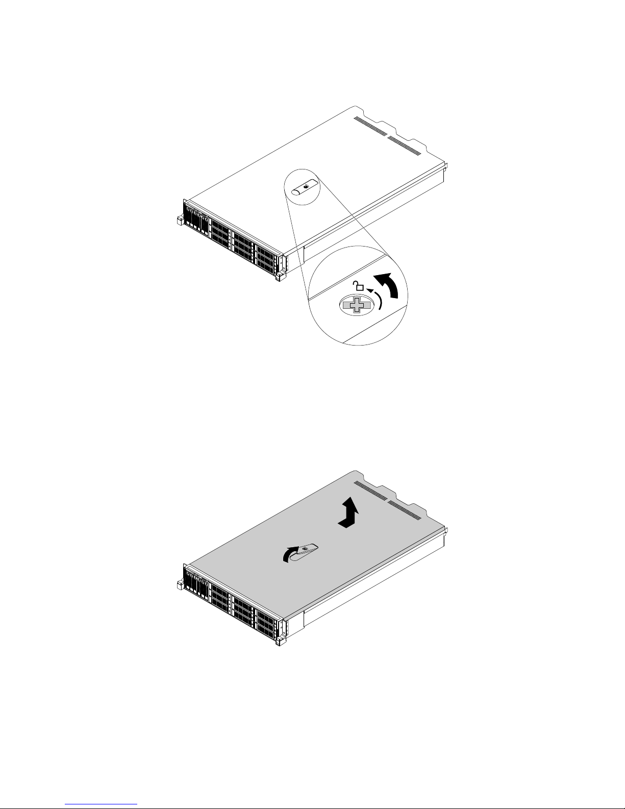
5.Useascrewdrivertounscrewthecoverlocktotheopenpositionasshown.
Figure38.Unscrewingthecoverlock
6.Fullyopenthecoverlatchasshownandslidetheservercovertotherearuntilitisdisengagedfromthe
chassis.Then,lifttheservercoveroffthechassisandsetitaside.
Note:Itisrecommendedthatyouwaitseveralminutestolettheservercoolbeforeremovingthe
servercover.
Figure39.Removingtheservercover
Attention:Forpropercoolingandairflow,installtheservercoverbeforeturningontheserver.Operatingthe
serverwiththeservercoverremovedmightdamageservercomponents.
Toreinstalltheservercover,see“Reinstallingtheservercoverandreconnectingcables”onpage183
.
70ThinkServerRD650UserGuideandHardwareMaintenanceManual
Page 85
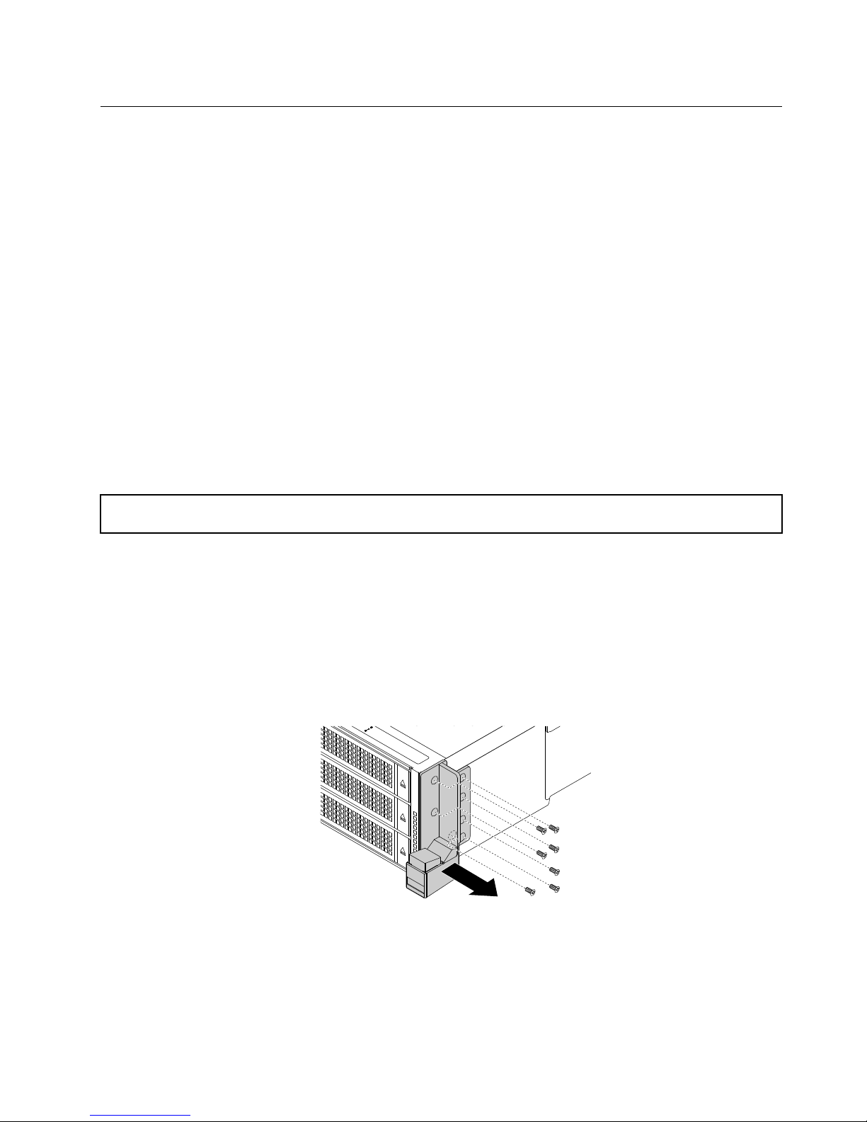
Installing,removing,orreplacinghardware
Thistopicprovidesinstructionsonhowtoinstall,remove,orreplacehardwareforyourserver.Youcan
expandthecapabilitiesofyourserverbyaddingnewhardwaredevices,suchasmemorymodules,PCIe
cards,orotherserveroptions,andmaintainyourserverbyreplacingthefailinghardwaredevices.
Ifyouarehandlingaserveroption,refertotheappropriateinstallationandorremovalinstructionsinthis
topicalongwiththeinstructionsthatcomewiththeoption.
Notes:
•UseonlypartsprovidedbyLenovo.
•Dependingonthemodel,yourservermightlookslightlydifferentfromtheillustrationsinthistopic.
TheEMIintegrityandcoolingoftheserverareprotectedbyhavingalldrivebaysandPCIcardslotscovered
oroccupied.WhenyouinstallaninternaldriveoraPCIcard,savetheEMIshieldordummytrayfromthe
drivebayorsavethePCIcardslotbracketintheeventthatyoulaterremovethedevice.
Attention:AnunoccupieddrivebayorPCIecardslotwithoutacover,shield,dummytray,filler,orany
otherprotectionmightimpacttheEMIintegrityandcoolingoftheserver,whichmightresultinoverheating
orcomponentdamage.
Removingandreinstallingtherackhandles
Attention:Donotopenyourserverorattemptanyrepairbeforereadingandunderstanding“Safetyinformation”
onpageiiiand“Guidelines”onpage67.
Beforeyoubegin,printalltherelatedinstructionsorensurethatyoucanviewthePDFversiononanother
computerforreference.
Note:Dependingonthemodel,yourservermightlookdifferentfromtheillustrationsinthistopic.
Toremoveandreinstalltherackhandles,dothefollowing:
1.Oneachsideoftheserver,removethescrewsthatsecuretherackhandleandthenremovetherack
handlefromthechassis.
Figure40.Removingtherackhandles
Chapter6.Replacinghardware71
Page 86
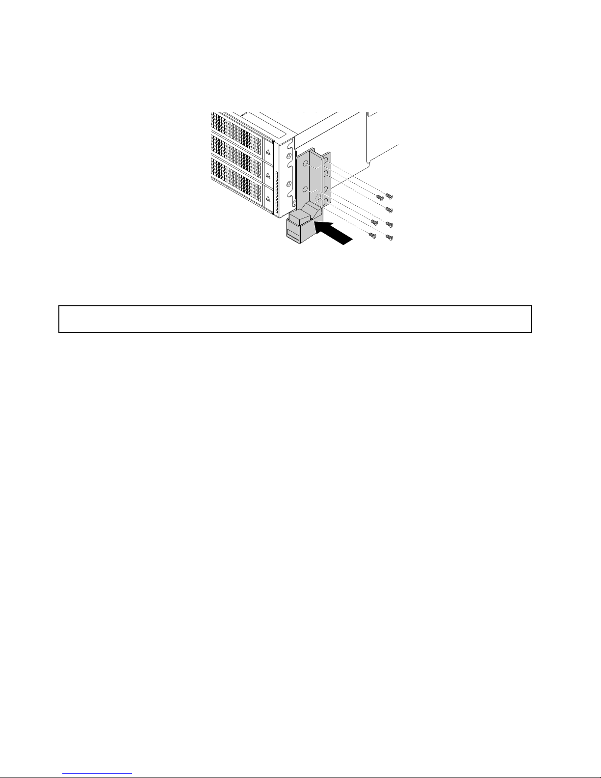
2.Toreinstalltherackhandles,alignthescrewholesintherackhandlewiththecorrespondingholesinthe
chassis.Installthescrewstosecuretherackhandleoneachsideoftheserver.
Figure41.Installingtherackhandles
Removingandreinstallingthecoolingshroud
Attention:Donotopenyourserverorattemptanyrepairbeforereadingandunderstanding“Safetyinformation”
onpageiii
and“Guidelines”onpage67.
Toaccesssomeoftheservercomponentsonthesystemboard,removethecoolingshroudfirst.Toensure
propercoolingandairflow,reinstallthecoolingshroudbeforeturningontheserver.
Beforeyoubegin,printalltherelatedinstructionsorensurethatyoucanviewthePDFversiononanother
computerforreference.
Toremoveandreinstallthecoolingshroud,dothefollowing:
1.Removeallmediafromthedrivesandturnoffallattacheddevicesandtheserver.Then,disconnectall
powercordsfromelectricaloutletsanddisconnectallcablesthatareconnectedtotheserver.
2.Prepareyourserver.See“Removingorextendingtheserverfromtherackcabinet”onpage69.
3.Removetheservercover.See“Removingtheservercover”onpage69.
4.RemovetheThinkServerRAIDSuperCapacitorModuleifoneisinstalledonthecoolingshroud.See
“RemovingtheThinkServerRAIDSuperCapacitorModule”onpage133.
72ThinkServerRD650UserGuideandHardwareMaintenanceManual
Page 87
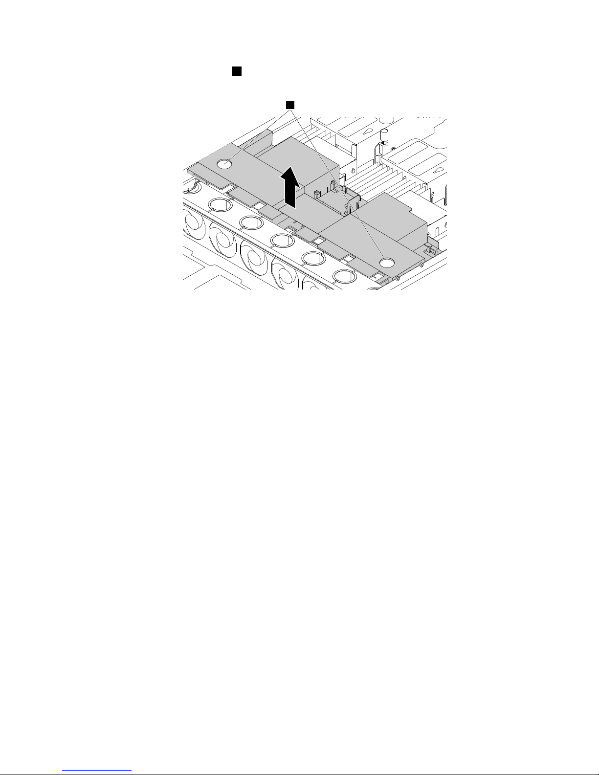
5.Insertyourfingersintotheholes1inthecoolingshroudandliftitoutoftheserver.
1
Figure42.Removingthecoolingshroud
Chapter6.Replacinghardware73
Page 88
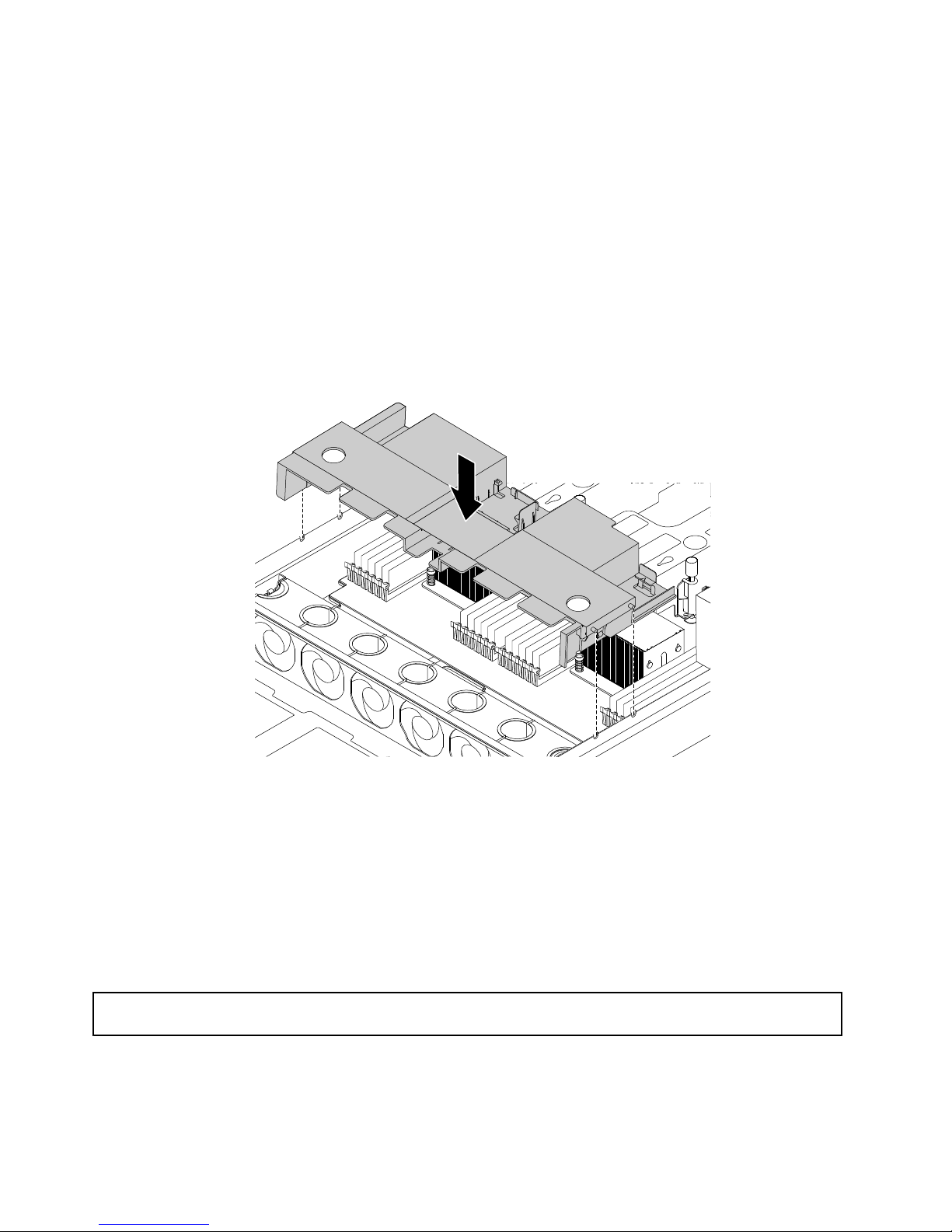
6.Toreinstallthecoolingshroud,dothefollowing:
a.Ensurethat:
•Allcomponentshavebeenreassembledcorrectly.
•Notoolsorloosescrewsareleftinsideyourserver.
•Allcablesinsidetheserverhavebeenproperlyroutedandtheywillnotinterferewithinstalling
thecoolingshroud.
b.Notetheorientationofthecoolingshroud.Alignthetabsonbothsidesofthecoolingshroudwith
thecorrespondingholesorgapsinbothsidesofthechassis.
c.Lowerthecoolingshroudintothechassisuntilitsnapsintoposition.
Note:Ifnecessary,gentlypressthecoolingshroudonbothsidessothatthetabsonthecoolingshroud
completelyengagewithbothsidesofthechassis.
Figure43.Installingthecoolingshroud
Attention:Forpropercoolingandairflow,reinstallthecoolingshroudbeforeturningontheserver.Operating
theserverwiththecoolingshroudremovedmightdamageservercomponents.
Whattodonext:
•Toworkwithanotherpieceofhardware,gototheappropriatesection.
•Tocompletethereplacement,goto“Completingthepartsreplacement”onpage183.
Installingorreplacingasystemfan
Attention:Donotopenyourserverorattemptanyrepairbeforereadingandunderstanding“Safetyinformation”
onpageiiiand“Guidelines”onpage67.
Yourserversupportsuptosixhot-swapsystemfans.Thisdesignhelpsyouavoidsignificantcooling
problemswhenasystemfanfails.Youcanreplaceasystemfanwithoutturningofftheserver.Tolocatethe
systemfans,see“Systemboardcomponents”onpage43.
74ThinkServerRD650UserGuideandHardwareMaintenanceManual
Page 89
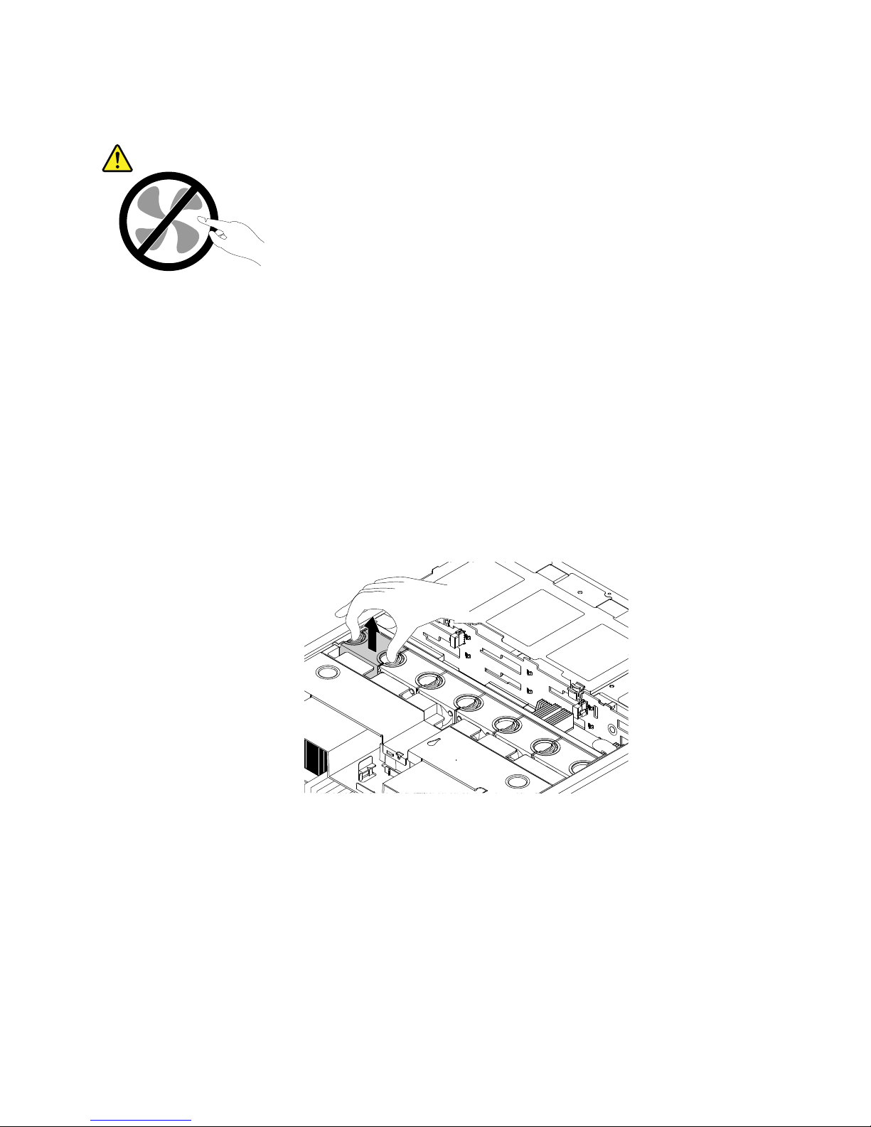
CAUTION:
Hazardousmovingparts.Keepfingersandotherbodypartsaway.
Beforeyoubegin,printalltherelatedinstructionsorensurethatyoucanviewthePDFversiononanother
computerforreference.
Note:Dependingonthemodel,yourservermightlookslightlydifferentfromtheillustrationsinthistopic.
Toinstallorreplaceasystemfan,dothefollowing:
1.Removetheservercover.
Note:Thesystemfansarehot-swapandyoucanreplaceafailingsystemfanwithoutturningoff
theserver.
2.Dooneofthefollowing:
•Ifyouareinstallingasystemfan,graspthetopofthedummyfanwithyourindexfingerandthumb
andthenliftthedummyfanoutoftheserver.
Figure44.Removingthedummyfan
•Ifyouarereplacingasystemfan,dothefollowing:
a.ViewthesystemfanfaultLEDtolocatethefailingsystemfan.See“SystemfanfaultLEDs”on
page49.
Chapter6.Replacinghardware75
Page 90
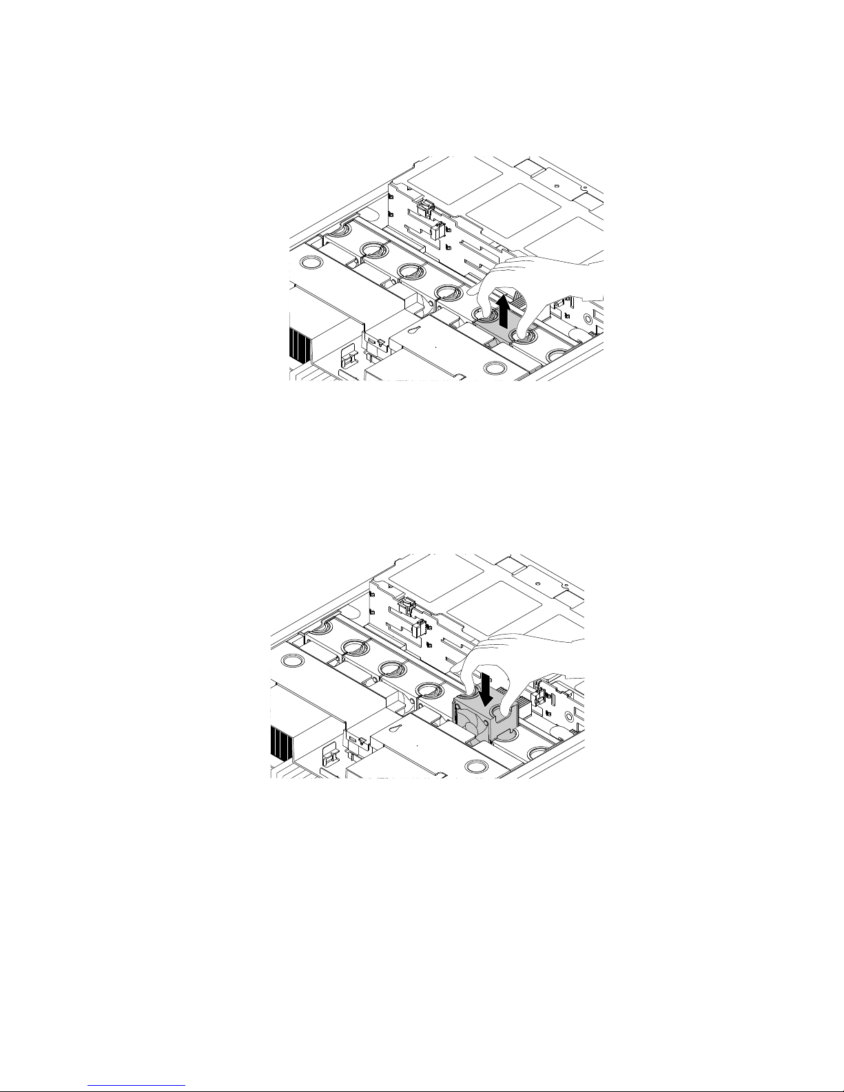
b.Graspthetopofthesystemfanwithyourindexfingerandthumbandthenliftthesystemfan
outoftheserver.
Figure45.Removingthesystemfan
3.Touchthestatic-protectivepackagethatcontainsthenewsystemfantoanyunpaintedsurfaceonthe
outsideoftheserver.Then,removethenewsystemfanfromthepackage.
4.Positionthenewsystemfanabovethesystemfancagesothatthesystemfanconnectoronthebottom
ofthenewsystemfanisfacingtherearofthechassis.Then,pressthenewsystemfanstraightdown
untilitisseatedintoplace.
Figure46.Installingthesystemfan
5.Ifyouareinstructedtoreturntheoldsystemfan,followallpackaginginstructionsanduseany
packagingmaterialsthataresuppliedtoyouforshipping.
Whattodonext:
•Toworkwithanotherpieceofhardware,gototheappropriatesection.
•Tocompletethereplacement,goto“Completingthepartsreplacement”onpage183
.
76ThinkServerRD650UserGuideandHardwareMaintenanceManual
Page 91
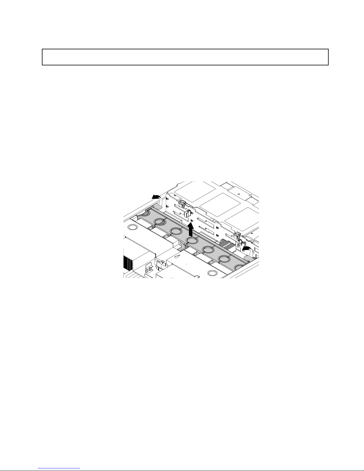
Removingandreinstallingthesystemfancage
Attention:Donotopenyourserverorattemptanyrepairbeforereadingandunderstanding“Safetyinformation”
onpageiiiand“Guidelines”onpage67.
Beforeyoubegin,printalltherelatedinstructionsorensurethatyoucanviewthePDFversiononanother
computerforreference.
Note:Y oucanremoveandreinstallthesystemfancagewithoutremovingthesystemfans.
Toremoveandreinstallthesystemfancage,dothefollowing:
1.Removeallmediafromthedrivesandturnoffallattacheddevicesandtheserver.Then,disconnectall
powercordsfromelectricaloutletsanddisconnectallcablesthatareconnectedtotheserver.
2.Prepareyourserver.See“Removingorextendingtheserverfromtherackcabinet”onpage69.
3.Removetheservercover.See“Removingtheservercover”onpage69.
4.Pivotthetabstotherearoftheserver.Then,removethesystemfancagewiththeinstalledsystemfans
asawholebyliftingthecagestraightupandoutofthechassis.
Figure47.Removingthesystemfancage
Chapter6.Replacinghardware77
Page 92
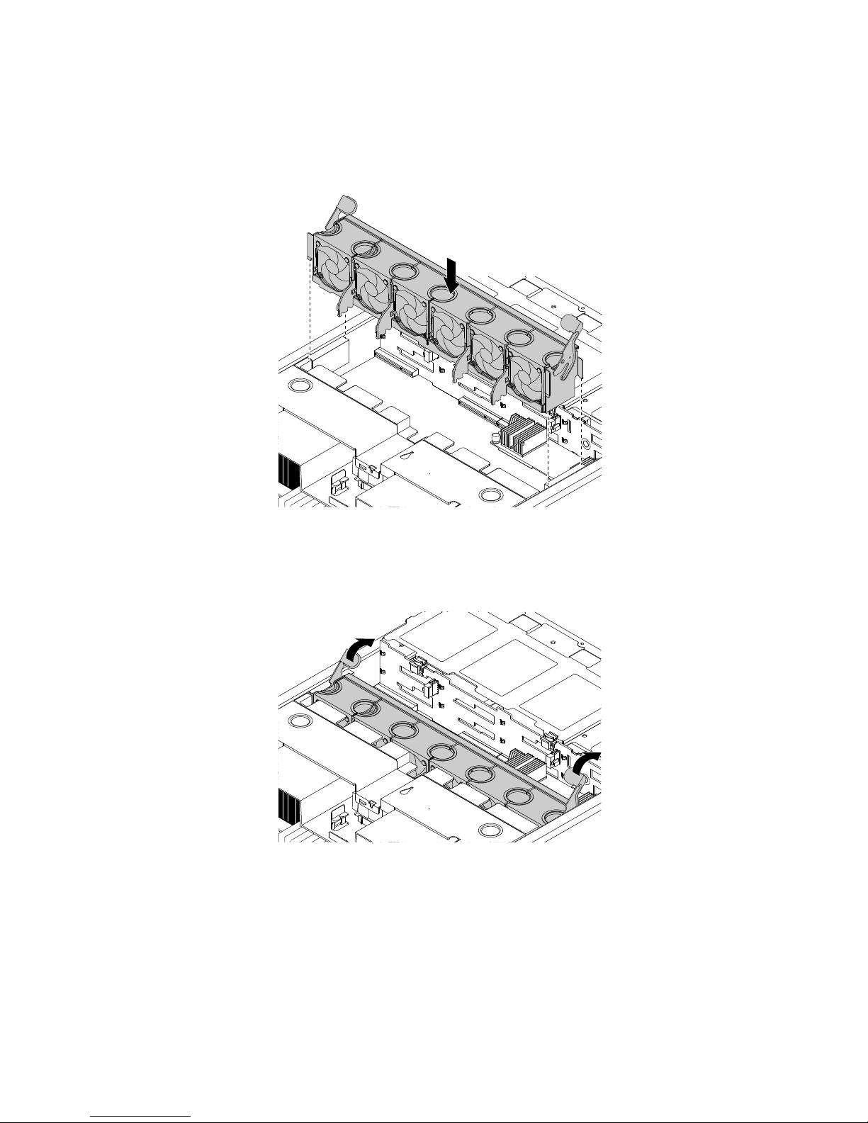
5.Notetheorientationofthesystemfancage.Aligntheleftandrightsidesofthesystemfancagewith
thecorrespondingmountingpostsinthechassis.Then,pressthesystemfancagewiththeinstalled
systemfansstraightdownintothechassis.Ensurethatthesystemfansarecorrectlyconnectedto
thesystemfanconnectorsonthesystemboard.
Figure48.Installingthesystemfancage
6.Pivotthetabsofthesystemfancagetothefrontoftheservertosecurethesystemfancage.
Figure49.Securingthesystemfancage
Whattodonext:
•Toworkwithanotherpieceofhardware,gototheappropriatesection.
•Tocompletethereplacement,goto“Completingthepartsreplacement”onpage183
.
Installingorremovingamemorymodule
Thistopicprovidesinstructionsonhowtoinstallorremoveamemorymodule.
78ThinkServerRD650UserGuideandHardwareMaintenanceManual
Page 93

Note:ThememorymodulesareextremelysensitivetoESD.Ensurethatyoureadandunderstand“Handling
static-sensitivedevices”onpage68firstandcarefullyperformtheoperation.
Memorymoduleinstallationrules
Yourserverhas24memoryslotsandithasthefollowingfeatures:
•Eachslotsupports4GB,8GB,and16GBdoubledatarate4registereddualinlinememorymodules
(DDR4RDIMMs)withErrorCheckingandCorrecting(ECC)technology.
•Eachslotsupports32GBdoubledatarate4loadreductiondualinlinememorymodules(DDR4
LRDIMMs)withErrorCheckingandCorrecting(ECC)technology.
•Yourserversupportsupto12memorymoduleswhenonemicroprocessorisinstalled.Supportsupto24
memorymoduleswhentwomicroprocessorsareinstalled.
•Theminimumsystemmemoryis4GB(onlyonemicroprocessorinstalledandonlyone4GBRDIMM
installedintheCPU1DIMMA1slot).
•Themaximumsystemmemoryis768GB(twomicroprocessorsinstalledandone32GBLRDIMM
installedineachofthe24memoryslots).
Formoreinformationaboutthememorymodulesinyourspecificservermodel,usetheSetupUtility
program.See“ViewinginformationintheSetupUtilityprogram”onpage55
.
ForalistofthesupportedThinkServermemorymoduleoptions,goto:
http://lenovoquickpick.com/usa/home/thinkserver/rack-and-tower-server
Beforeinstallingamemorymodule,ensurethatyouobservethefollowingguidelines:
•Allmemorymodulestobeinstalledmustbethesametype.Yourserversupportsthefollowingtypes
ofmemorymodules:
–DDR4RDIMMwithECCtechnology
–DDR4LRDIMMwithECCtechnology
•Whenyouinstallmemorymoduleswithdifferentranksinonechannel,startfromthefarthestmemoryslot
inthechannel.Installthememorymodulethathasthemostranksfirst.
•Whenyouinstallmemorymoduleswithdifferentfrequenciesintothememoryslotsforthesame
microprocessor,allthememorymodulesrunatthelowestfrequency.
•Itisrecommendedthatyouinstallthehigh-frequencymemorymodulesintothememoryslotsforthe
samemicroprocessortoensurehighperformance.
Chapter6.Replacinghardware79
Page 94
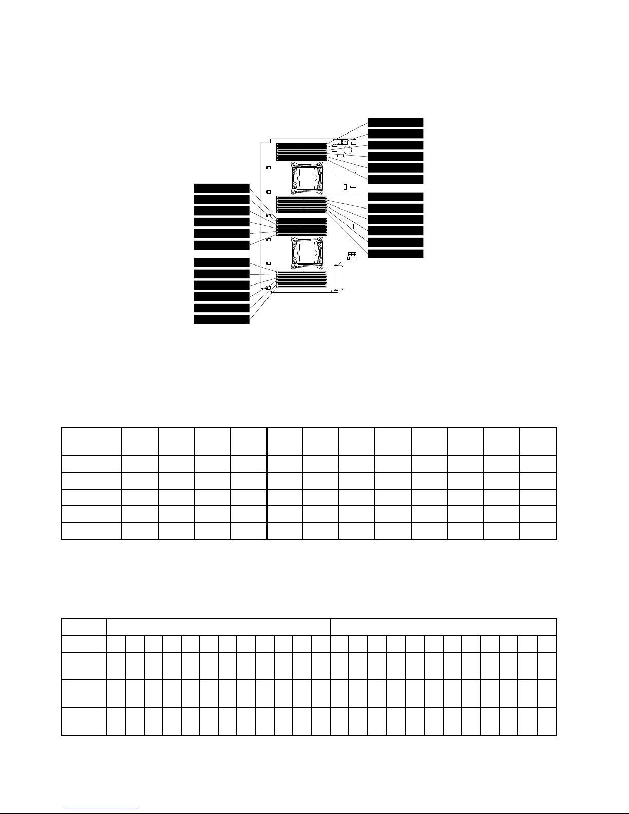
Thefollowingillustrationhelpsyoutolocatethememoryslotsonthesystemboard.Thefollowingillustration
showsthesystemboardwithtwoinstalledmicroprocessors(alsoknownasCPU).
CPU1 DIMMC1
CPU1 DIMMC2
CPU1 DIMMC3
CPU1 DIMMD1
CPU1 DIMMD2
CPU1 DIMMD3
CPU1 DIMMB3
CPU1 DIMMB2
CPU1 DIMMB1
CPU1 DIMMA3
CPU1 DIMMA2
CPU1 DIMMA1
CPU2 DIMMC1
CPU2 DIMMC2
CPU2 DIMMC3
CPU2 DIMMD1
CPU2 DIMMD2
CPU2 DIMMD3
CPU2 DIMMB3
CPU2 DIMMB2
CPU2 DIMMB1
CPU2 DIMMA3
CPU2 DIMMA2
CPU2 DIMMA1
Figure50.Memoryslotsonthesystemboard
Thefollowingtableprovidesinformationaboutthememorymoduleinstallationrulesforserversthathave
onlyonemicroprocessor(CPU1)installed.The“X”markindicatesthememoryslotsintowhichthememory
modulesshouldbeinstalledindifferentsituations.
Table2.Memorymoduleinstallationrulesforserverswithonemicroprocessor
CPU1
DIMM
A1A2A3B1B2B3
C1C2C3
D1D2D3
1DIMMX
2DIMMsXX
4DIMMsXXXX
8DIMMsXXXXXXXX
12DIMMsXXXXXXXXXXXX
Thefollowingtableprovidesinformationaboutthememorymoduleinstallationrulesforserversthathave
twomicroprocessors(CPU1andCPU2)installed.The“X”markindicatesthememoryslotsintowhichthe
memorymodulesshouldbeinstalledindifferentsituations.
Table3.Memorymoduleinstallationrulesforserverswithtwomicroprocessors
CPU1DIMMCPU2DIMM
A1A2A3B1B2B3
C1C2C3
D1D2D3A1A2A3B1B2B3
C1C2C3
D1D2D3
2
DIMMs
XX
4
DIMMs
XXXX
8
DIMMs
XXXXXXXX
80ThinkServerRD650UserGuideandHardwareMaintenanceManual
Page 95
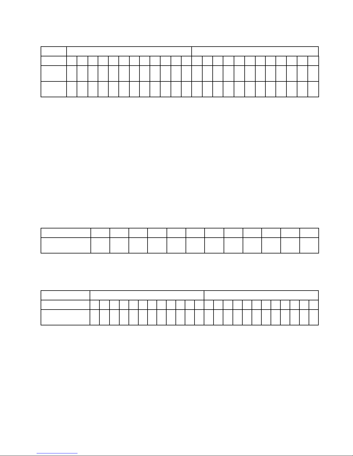
Table3.Memorymoduleinstallationrulesforserverswithtwomicroprocessors(continued)
CPU1DIMMCPU2DIMM
A1A2A3B1B2B3
C1C2C3
D1D2D3A1A2A3B1B2B3
C1C2C3
D1D2D3
16
DIMMs
XXXXXXXXXXXXXXXX
24
DIMMs
XXXXXXXXXXXXXXXXXXXXXXXX
Thefollowingsectionexplainsthememorymoduleinstallationrulesinindependentmode,mirroringmode,
sparingmode,andlockstepmode.
Memorymoduleinstallationorderinindependentmode
Inindependentmode,theRASfeaturesarenotavailable.FormoreinformationabouttheRASfeatures,
refertotherelatedsectionin“Features”onpage7.
Notes:
•Allmemorymodulestobeinstalledmustbethesametype.
•Whenyouinstallmemorymoduleswithdifferentcapacity,installthememorymodulethathasthe
highestcapacityfirst.
Thefollowingtableexplainsthememorymoduleinstallationorderforserversthathaveonlyone
microprocessor(CPU1)installed.
Table4.Memorymoduleinstallationorderinindependentmodeforserverswithonemicroprocessor
CPU1DIMM
A1A2A3B1B2B3
C1C2C3
D1D2D3
DIMMinstallation
order
1
5
926103
7
114812
Thefollowingtableexplainsthememorymoduleinstallationorderforserversthathavetwomicroprocessors
(CPU1andCPU2)installed.
Table5.Memorymoduleinstallationorderinindependentmodeforserverswithtwomicroprocessors
CPU1DIMMCPU2DIMM
A1A2A3B1B2B3
C1C2C3
D1D2D3A1A2A3B1B2B3
C1C2C3
D1D2D3
DIMMinstallation
order
191731119
5
1321
7
152321018412206142281624
Memorymoduleinstallationorderinmirroringmode
Inmirroringmode,theservermaintainstwoidenticalcopiesofalldatainmemoryandtheRASfeaturesare
available.FormoreinformationabouttheRASfeatures,refertotherelatedsectionin“Features”onpage7
.
Notes:
•Allmemorymodulestobeinstalledmustbethesametypewiththesamecapacity,frequency,voltage,
andnumberofranks.
•Allmemorymodulesmustbeinstalledinpairs.
Chapter6.Replacinghardware81
Page 96
Thefollowingtableexplainsthememorymoduleinstallationorderforserversthathaveonlyone
microprocessor(CPU1)installed.
Table6.Memorymoduleinstallationorderinmirroringmodeforserverswithonemicroprocessor
CPU1DIMM
A1A2A3B1B2B3
C1C2C3
D1D2D3
DIMMinstallation
order
13
5
13
5
246246
Thefollowingtableexplainsthememorymoduleinstallationorderforserversthathavetwomicroprocessors
(CPU1andCPU2)installed.
Table7.Memorymoduleinstallationorderinmirroringmodeforserverswithtwomicroprocessors
CPU1DIMMCPU2DIMM
A1A2A3B1B2B3
C1C2C3
D1D2D3A1A2A3B1B2B3
C1C2C3
D1D2D3
DIMMinstallation
order
1
5
91
5
93
7
113
7
112610261048124812
Memorymoduleinstallationorderinsparingmode
Thesparingmodeprovidesmemoryredundancy.Inthismode,theRASfeaturesareavailable.Formore
informationabouttheRASfeatures,refertotherelatedsectionin“Features”onpage7.
Note:Allmemorymodulestobeinstalledmustbethesametypewiththesamecapacity,frequency,
voltage,andnumberofranks.
Yourserversupportsranksparingmode.Inranksparingmode,onerankofamemorymoduleworksasthe
sparerankfortheotherranksonthesamechannel.Thesparerankisnotavailableassystemmemory.To
enableranksparingmode,ensurethat:
•Atleastthreeranksareavailableinonechannel.
•Atleasttwomemorymodulesareinstalledinonechannel.
Thefollowingtableexplainsthememorymoduleinstallationorderforserversthathaveonlyone
microprocessor(CPU1)installed.
Table8.Memorymoduleinstallationorderinsparingmodeforserverswithonemicroprocessor
CPU1DIMM
A1A2A3B1B2B3
C1C2C3
D1D2D3
DIMMinstallation
order
11
5
22633
7
448
Thefollowingtableexplainsthememorymoduleinstallationorderforserversthathavetwomicroprocessors
(CPU1andCPU2)installed.
Table9.Memorymoduleinstallationorderinsparingmodeforserverswithtwomicroprocessors
CPU1DIMMCPU2DIMM
A1A2A3B1B2B3
C1C2C3
D1D2D3A1A2A3B1B2B3
C1C2C3
D1D2D3
DIMMinstallation
order
1193311
55
13
77
152210441266148816
82ThinkServerRD650UserGuideandHardwareMaintenanceManual
Page 97
Memorymoduleinstallationorderinlockstepmode
Inlockstepmode,theRASfeaturesareavailable.FormoreinformationabouttheRASfeatures,refertothe
relatedsectionin“Features”onpage7.
Notes:
•Allmemorymodulestobeinstalledmustbethesametypewiththesamecapacity,frequency,voltage,
andnumberofranks.
•Allmemorymodulesmustbeinstalledinpairs.
Thefollowingtableexplainsthememorymoduleinstallationorderforserversthathaveonlyone
microprocessor(CPU1)installed.
Table10.Memorymoduleinstallationorderinlockstepmodeforserverswithonemicroprocessor
CPU1DIMM
A1A2A3B1B2B3
C1C2C3
D1D2D3
DIMMinstallation
order
13
5
13
5
246246
Thefollowingtableexplainsthememorymoduleinstallationorderforserversthathavetwomicroprocessors
(CPU1andCPU2)installed.
Table11.Memorymoduleinstallationorderinlockstepmodeforserverswithtwomicroprocessors
CPU1DIMMCPU2DIMM
A1A2A3B1B2B3
C1C2C3
D1D2D3A1A2A3B1B2B3
C1C2C3
D1D2D3
DIMMinstallation
order
1193311
55
13
77
152210441266148816
Installingamemorymodule
Attention:Donotopenyourserverorattemptanyrepairbeforereadingandunderstanding“Safetyinformation”
onpageiii
and“Guidelines”onpage67.
Beforeyoubegin,printalltherelatedinstructionsorensurethatyoucanviewthePDFversiononanother
computerforreference.
Notes:
•Ensurethatyouconsiderandfollowthememorymoduleinstallationruleswhenperformingtheoperation.
See“Memorymoduleinstallationrules”onpage79.
•Useanydocumentationthatcomeswiththememorymoduleandfollowthoseinstructionsinadditionto
theinstructionsinthistopic.
Toinstallamemorymodule,dothefollowing:
1.Removeallmediafromthedrivesandturnoffallattacheddevicesandtheserver.Then,disconnectall
powercordsfromelectricaloutletsanddisconnectallcablesthatareconnectedtotheserver.
2.Prepareyourserver.See“Removingorextendingtheserverfromtherackcabinet”onpage69.
3.Removetheservercover.See“Removingtheservercover”onpage69.
4.Removethecoolingshroud.See“Removingandreinstallingthecoolingshroud”onpage72.
5.Locatethememoryslotsonthesystemboardandreadthememorymoduleinstallationrules.See
“Memorymoduleinstallationrules”onpage79.Removethememorydummyifnecessary.
Chapter6.Replacinghardware83
Page 98
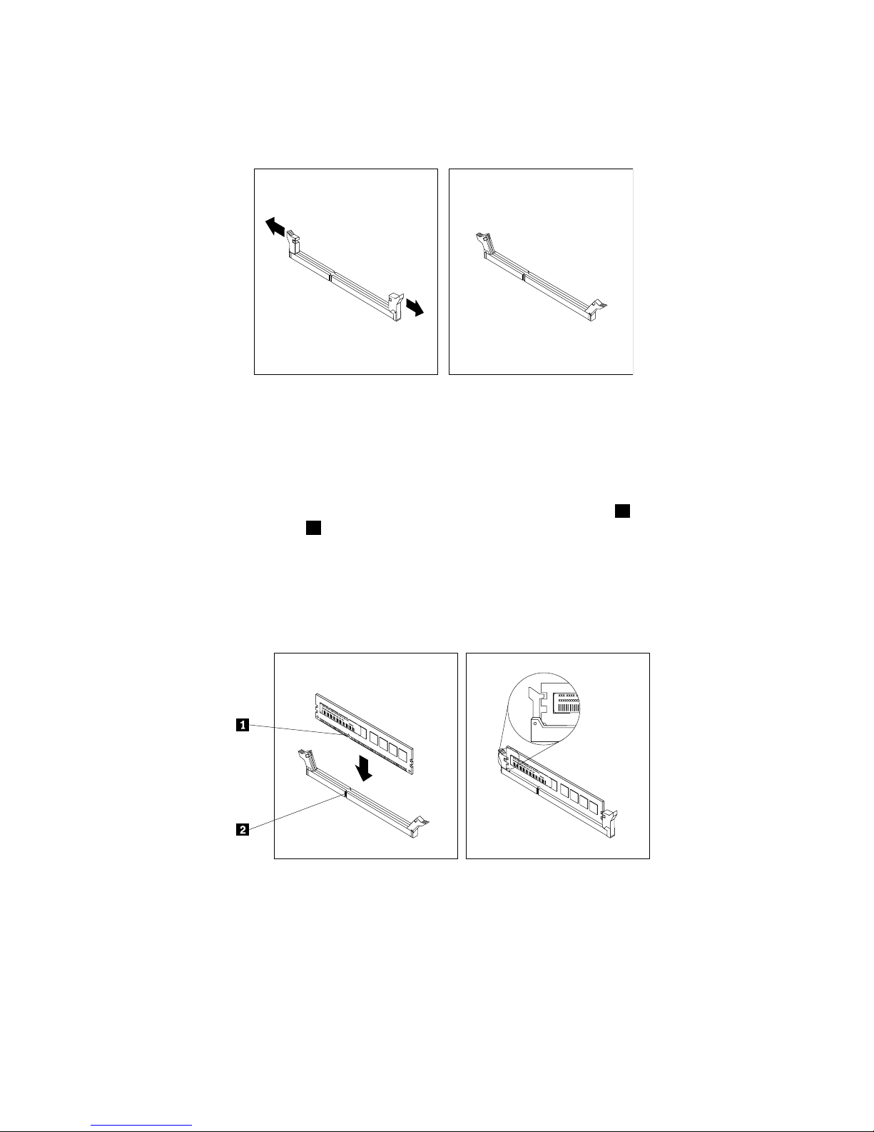
6.Disconnectanycablesthatmightimpedeyouraccesstothememoryslots.
7.Opentheretainingclipsoftheappropriatememoryslot.
Figure51.Openingtheretainingclipsofthememoryslot
8.Touchthestatic-protectivepackagethatcontainsthenewmemorymoduletoanyunpaintedsurfaceon
theoutsideoftheserver.Then,takethenewmemorymoduleoutofthepackage.
Note:Carefullyhandlethememorymodulebyitsedges.
9.Positionthenewmemorymoduleoverthememoryslot.Ensurethatthenotch1onthenewmemory
moduleisalignedwiththekey2inthememoryslot.Then,pressthenewmemorymodulestraightdown
intothememoryslotuntiltheretainingclipscloseandthenewmemorymodulesnapsintoposition.
Note:Ifthereisagapbetweenthememorymoduleandtheretainingclips,thememorymodulehas
notbeencorrectlyinstalled.Opentheretainingclips,removethememorymodule,andthenreinstallit
intothememoryslotuntiltheretainingclipsarecompletelyclosed.
Figure52.Installingamemorymodule
10.Reconnectanycablesthatyouhavedisconnected.
Whattodonext:
•Toworkwithanotherpieceofhardware,gototheappropriatesection.
•Tocompletetheinstallation,goto“Completingthepartsreplacement”onpage183
.
84ThinkServerRD650UserGuideandHardwareMaintenanceManual
Page 99
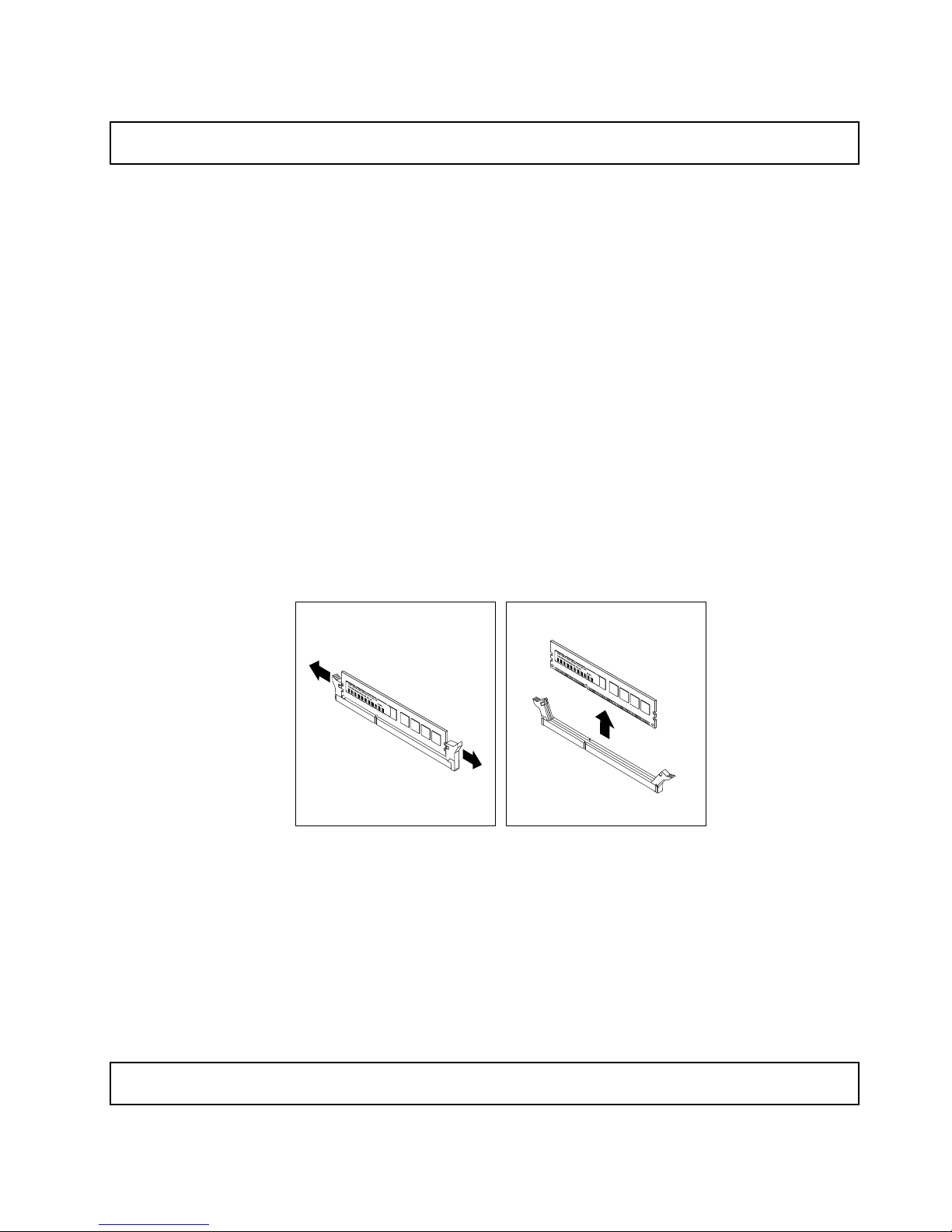
Removingamemorymodule
Attention:Donotopenyourserverorattemptanyrepairbeforereadingandunderstanding“Safetyinformation”
onpageiiiand“Guidelines”onpage67.
Beforeyoubegin,printalltherelatedinstructionsorensurethatyoucanviewthePDFversiononanother
computerforreference.
Note:Ensurethatyouconsiderandfollowthememorymoduleinstallationruleswhenperformingthe
operation.See“Memorymoduleinstallationrules”onpage79
.
Toremoveamemorymodule,dothefollowing:
1.Removeallmediafromthedrivesandturnoffallattacheddevicesandtheserver.Then,disconnectall
powercordsfromelectricaloutletsanddisconnectallcablesthatareconnectedtotheserver.
2.Prepareyourserver.See“Removingorextendingtheserverfromtherackcabinet”onpage69.
3.Removetheservercover.See“Removingtheservercover”onpage69.
4.Removethecoolingshroud.See“Removingandreinstallingthecoolingshroud”onpage72.
5.Locatethememoryslotsonthesystemboardandreadthememorymoduleinstallationrules.See
“Memorymoduleinstallationrules”onpage79.
6.Disconnectanycablesthatmightimpedeyouraccesstothememoryslots.
7.Locatethememorymodulethatyouwanttoremoveandopentheretainingclipsonbothendsofthe
memoryslot.Then,graspthememorymodulebyitsedgesandcarefullypullitstraightuptoremoveit
fromthememoryslot.
Figure53.Removingamemorymodule
8.Ifyouareinstructedtoreturntheoldmemorymodule,followallpackaginginstructionsanduseany
packagingmaterialsthataresuppliedtoyouforshipping.
Whattodonext:
•Toworkwithanotherpieceofhardware,gototheappropriatesection.
•Tocompletetheremovalprocedure,goto“Completingthepartsreplacement”onpage183.
Replacingtherisercard
Attention:Donotopenyourserverorattemptanyrepairbeforereadingandunderstanding“Safetyinformation”
onpageiiiand“Guidelines”onpage67.
Chapter6.Replacinghardware85
Page 100
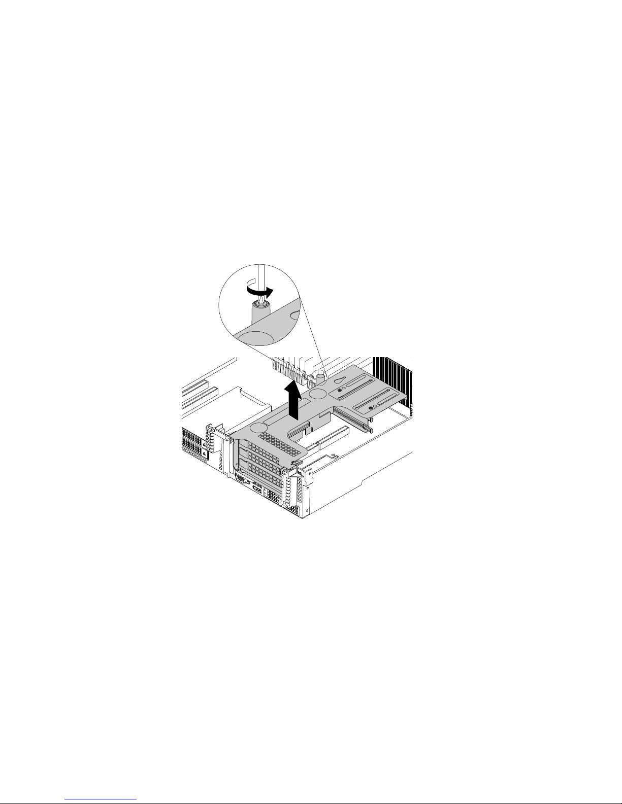
Beforeyoubegin,printalltherelatedinstructionsorensurethatyoucanviewthePDFversiononanother
computerforreference.
Note:Thefollowingprocedureisbasedonthescenariothattherisercardisinstalledontherisercard
bracket1.Theprocedureissimilarforrisercardinstalledontherisercardbracket2.
Toreplacetherisercard,dothefollowing:
1.Removeallmediafromthedrivesandturnoffallattacheddevicesandtheserver.Then,disconnectall
powercordsfromelectricaloutletsanddisconnectallcablesthatareconnectedtotheserver.
2.Prepareyourserver.See“Removingorextendingtheserverfromtherackcabinet”onpage69.
3.Removetheservercover.See“Removingtheservercover”onpage69.
4.Loosenthescrewthatsecurestherisercardassembly.Then,grasptheassemblybyitsedgesand
carefullyliftitstraightupandoffthechassis.
Figure54.Removingtherisercardassemblyfromthechassis
5.IfthereisanyPCIecardinstalledontherisercard,recordthecableconnectionsfirst.Then,disconnect
allcablesfromthecardsandcompletelyremovetherisercardassemblyoutofthechassis.
6.RemovethePCIecardsthatareinstalledontherisercard.See“RemovingaPCIecardfromtheriser
cardassembly”onpage98.
86ThinkServerRD650UserGuideandHardwareMaintenanceManual
 Loading...