

Lenovo ThinkServer 0390, ThinkServer 0387, ThinkServer 0391, ThinkServer 0392, ThinkServer 0393 User Manual
...Page 1
ThinkServer
UserGuide
MachineTypes:0387,0388,0389,0390,0391,0392,0393,and0441
Page 2

Note:
Beforeusingtheinformationandtheproductitsupports,besuretoreadandunderstandthefollowing:
•TheReadMeFirstthatcomeswithyourproduct
•“Safetyinformation”onpageiii
•AppendixA“Notices”onpage179
FirstEdition(June2011)
©CopyrightLenovo2011.
LIMITEDANDRESTRICTEDRIGHTSNOTICE:IfdataorsoftwareisdeliveredpursuantaGeneralServicesAdministration
“GSA”contract,use,reproduction,ordisclosureissubjecttorestrictionssetforthinContractNo.GS-35F-05925.
Page 3

Contents
Safetyinformation..........iii
Chapter1.Generalinformation.....1
Introduction.................1
Serverdocumentation.............2
Chapter2.Serversetuproadmap...5
Chapter3.Productoverview......7
Serverpackage...............7
Features..................7
Specications...............12
Software.................12
ThinkServerEasyStartup.........12
ThinkServerEasyUpdateFirmwareUpdater.13
BIOSandBMCrmwareupdateutility...13
RAIDcongurationutilities........13
PC-DoctorforDOS...........13
Locations.................13
Machinetype,model,andserialnumber
label.................13
Frontviewoftheserver.........15
Frontpanel..............17
DITmodule..............18
Rearviewoftheserver.........19
Serverlocks..............22
Servercomponents...........25
Hot-swapharddiskdrivestatusLEDs...32
RAIDcard...............33
Hot-swapharddiskdrivebackplane....34
Systemboardcomponents........42
Systemboardjumpers..........46
SystemboardLEDs...........50
Chapter4.T urningonandturningoff
theserver...............53
Turningontheserver............53
Turningofftheserver............53
Chapter5.Conguringtheserver..55
UsingtheSetupUtilityprogram........55
StartingtheSetupUtilityprogram.....55
ViewinginformationintheSetupUtility
program...............55
SetupUtilityprograminterface......56
Settingthesystemdateandtime.....64
Usingpasswords............65
ConguringtheTPMfunction.......66
Selectingastartupdevice........66
ExitingtheSetupUtilityprogram......67
UpdatingorrecoveringtheBIOS......67
UsingtheThinkServerEasyStartupprogram...69
FeaturesoftheThinkServerEasyStartup
program...............70
StartingtheThinkServerEasyStartup
program...............70
ConguringRAID..............71
AboutRAID..............72
RAIDforyourserver...........73
ConguringRAIDusingtheThinkServer
EasyStartupprogram..........74
ConguringtheonboardSATAsoftware
RAID.................75
ConguringtheadvancedSATAorSAS
hardwareRAID.............80
ConguringtheEthernetcontrollers......81
Updatingthermware............81
UsingtheFirmwareUpdaterprogram....81
Chapter6.Installing,removing,or
replacinghardware..........83
Guidelines................83
Precautions..............83
Handlingstatic-sensitivedevices.....84
Systemreliabilityguidelines........84
Workinginsidetheserverwiththepoweron.85
Removingtheservercover..........85
Removingandreinstallingthefrontbezel....87
Installing,removing,orreplacinghardware...89
Installingorremovingamemorymodule...89
InstallingorremovingaPCIcard......93
InstallingorremovingtheEthernetcard...96
InstallingorremovingtheRAIDcard....98
InstallingorremovingtheThinkServer9240-8i
RAID5UpgradeKey..........100
InstallingorremovingtheThinkServerSATA
SoftwareRAID5Key..........102
InstallingorremovingtheThinkServeriKVM
RemoteManagementModule.......105
InstallingorremovingtheTPMmodule...109
InstallingorremovingtheDITmodule....111
Installingorreplacinganopticaldrive....115
Installingorreplacingahot-swapharddisk
drive.................119
Removingorinstallinganon-hot-swaphard
diskdrive...............123
©CopyrightLenovo2011
i
Page 4

Replacingthehot-swapharddiskdrive
backplane...............133
Replacingthenon-hot-swappowersupply
assembly...............137
Replacingahot-swapredundantpower
supplymodule.............140
Replacingthepowerdistributionboardand
cageassembly.............143
Replacingthefrontpanelboardassembly..147
Replacingthefrontsystemfan......149
Replacingtherearsystemfan.......152
Replacingtheheatsinkandfanassembly..154
Replacingthemicroprocessor.......157
Replacingthesystemboardbattery....161
Completingthepartsreplacement.......162
Reinstallingtheservercoverandreconnecting
cables................162
Updatingtheserverconguration.....164
Chapter7.T roubleshootingand
diagnostics.............167
Troubleshootingprocedure..........167
ViewingthestatusanddiagnosticLEDs.....167
Usingthediagnosticprogram.........168
Viewingthesystemeventlog.........168
Basictroubleshootingtables.........168
ThinkServerEasyStartupprogram
problems...............168
Opticaldriveproblems..........169
Harddiskdriveproblems.........170
Memorymoduleproblems........172
Keyboard,mouse,orUSBdeviceproblems..172
Chapter8.Gettinginformation,help,
andservice.............175
Informationresources............175
Usingthedocumentation.........175
ThinkServerWebsite
(http://www.lenovo.com/thinkserver)....175
LenovoSupportWebsite.........175
Helpandservice..............176
Beforeyoucall.............176
Callingforservice............176
Usingotherservices..........177
Purchasingadditionalservices......177
AppendixA.Notices.........179
Trademarks................180
Importantnotes..............180
PolyvinylChloride(PVC)cableandcordnotice..180
Recyclinginformation............180
Batteryreturnprogram..........181
Requirementforbatteriescontaining
perchlorate..............182
Particulatecontamination..........182
ImportantinformationfortheEuropeanDirective
2002/96/EC................183
RestrictionofHazardousSubstancesDirective
(RoHS)..................186
ChinaRoHS..............187
Turkishstatementofcompliance......187
GermanOrdinanceforWorkglossstatement...188
Electronicemissionnotices..........188
FederalCommunicationsCommission(FCC)
Statement...............188
Index.................191
iiThinkServerUserGuide
Page 5
Safetyinformation
Note:Beforeusingtheproduct,besuretoreadandunderstandthemultilingualsafetyinstructionsonthe
documentationDVDthatcomeswiththeproduct.
Antesdeusaroproduto,leiaeentendaasinstruçõesdesegurançamultilínguesnoDVDdedocumentação
queoacompanha.
Предидаизползватетозипродукт,задължителнопрочететеивникнетевмногоезичнитеинструкции
забезопасноствDVDдискасдокументация,койтосепредоставяспродукта.
PrijeupotrebeovogproizvodaobaveznopročitajtevišejezičnesigurnosneuputekojesenalazenaDVD-us
dokumentacijomkojidobivateuzproizvod.
PředpoužitímproduktujetřebasipřečístaporozumětbezpečnostnímpokynůmuvedenýmnadiskuDVDs
dokumentací,kterýjedodávánsproduktem.
Førdubrugerproduktet,skaldusørgeforatlæseogforstådesikkerhedsforskrifter,derndespåere
sprog,pådendokumentations-dvd,derfølgermedproduktet.
LuetuotteenmukanatoimitetullaDVD-tietolevylläolevatmonikielisetturvaohjeetennentämäntuotteen
käyttöä.
Avantd'utiliserleproduit,veillezàbienlireetcomprendrelesinstructionsdesécuritémultilinguesgurant
surleDVDdedocumentationfourniavecleproduit.
Πρινχρησιμοποιήσετετοπροϊόν,βεβαιωθείτεότιέχετεδιαβάσεικαικατανοήσειτιςοδηγίεςασφάλειας,οι
οποίεςείναιδιαθέσιμεςσεδιάφορεςγλώσσεςστοDVDτεκμηρίωσηςπουσυνοδεύειτοπροϊόν.
VorVerwendungdesProduktssolltenSieunbedingtdiemehrsprachigenSicherheitsanweisungenaufder
Dokumentations-DVDlesen,dieimLieferumfangdesProduktsenthaltenist.
AtermékhasználataelőttmindenképpenolvassaelésértelmezzeatermékhezkapottdokumentációsDVD
lemezentalálható,többnyelvenelolvashatóbiztonságielőírásokat.
Primadiutilizzareilprodotto,accertarsidileggereecomprendereleinformazionisullasicurezzamultilingue
disponibilisulDVDdidocumentazionefornitoconilprodotto.
製品をご使用になる前に、製品に付属のDocumentationDVDに収録されているマルチリンガルの「安
全に正しくご使用いただくために」を読んで理解してください。
제품을사용하기전에제품과함께제공되는문서DVD의다국어안전지침을주의깊게읽어보십시오.
Voordatuhetproductgebruikt,moetuervoorzorgendatudemeertaligeveiligheidsinstructiesopde
documentatie-dvdvanhetproducthebtgelezenenbegrijpt.
©CopyrightLenovo2011
iii
Page 6

Przedskorzystaniemzproduktunależyzapoznaćsięzwielojęzycznymiinstrukcjamibezpieczeństwa
znajdującymisięnapłycieDVDzdokumentacjądostarczonąwrazzproduktem.
Antesdeutilizaroproduto,leiaatentamenteasinstruçõesdesegurançamultilinguesqueconstamno
DVDdedocumentaçãofornecidocomoproduto.
Înaintedeautilizaprodusul,asiguraţi-văcăaţicititşiînţelesinstrucţiuniledesiguranţăînmaimultelimbide
peDVD-ulcudocumentaţiecareînsoţeşteprodusul.
Førdubrukerproduktet,måduleseogforstådenerspråkligesikkerhetsinformasjonenpåDVDenmed
dokumentasjonsomfølgermedproduktet.
Преждечемиспользоватьэтотпродукт,внимательноознакомьтесьсинструкциямипотехнике
безопасностинаразныхязыках,которыеможнонайтинаDVD-дискесдокументациейвкомплектес
продуктом.
在使用本产品之前,请务必先阅读和了解产品附带的文档DVD中的多语言安全说明。
Prenegotoupotrebiteproizvodobaveznopaljivoproitajteiprouiteviejezikouputstvozabezbednostna
dokumentacionomDVD-ukojistedobiliuzproizvod.
PredpouvanmproduktusipretajteviacjazynbezpenostnpokynynadiskuDVDsdokumentcioudodanoms
produktom.
Predenzačneteuporabljatiizdelek,jepomembno,daprebereteinrazumetevečjezičnavarnostnanavodila
naDVD-juzdokumentacijo,kistegaprejeliskupajzizdelkom.
Antesdeutilizarelproducto,asegúresedeleerycomprenderlasinstruccionesdeseguridadmultilingüesdel
DVDdedocumentaciónqueseproporcionaconelproducto.
Varnogamedattläsasäkerhetsinstruktionernapådokumentations-DVD-skivansomföljermedprodukten
innandubörjaranvändaprodukten.
使用本產品之前,請務必閱讀並瞭解產品隨附的文件DVD上的多國語言版本安全資訊。
Buürünükullanmadanönce,ürünlebirliktegönderilenbelgeDVD'siüzerindekiçokdiliçerengüvenlik
yönergeleriniokuyupanladýðýnýzdaneminolun.
Передвикористаннямцьогопродуктууважноознайомтесязінструкціямизтехнікибезпекинарізних
мовах,щоможназнайтинаDVD-дискуздокументацієювкомплектізпродуктом.
Important:Eachcautionanddangerstatementinthistopicislabeledwithanumber.Thisnumberis
usedtocrossreferenceanEnglish-languagecautionordangerstatementwithtranslatedversionsofthe
cautionordangerstatementintheSafetyInformationdocument.Forexample,ifadangerstatementis
labeled“Statement1,”translationsforthisdangerstatementareintheSafetyInformationdocumentunder
“Statement1.”
Besuretoreadandunderstandallcautionanddangerstatementsinthisdocumentbeforeyouperformthe
procedures.Readandunderstandanyadditionalsafetyinformationthatcomeswiththeserveroroptional
devicebeforeyouinstall,remove,orreplacethedevice.
ivThinkServerUserGuide
Page 7

Statement1
DANGER
Electricalcurrentfrompower,telephone,andcommunicationcablesishazardous.
Toavoidashockhazard:
•Donotconnectordisconnectanycablesorperforminstallation,maintenance,orrecongurationofthis
productduringanelectricalstorm.
•Connectallpowercordstoaproperlywiredandgroundedelectricaloutlet.
•Connecttoproperlywiredoutletsanyequipmentthatwillbeattachedtothisproduct.
•Whenpossible,useonehandonlytoconnectordisconnectsignalcables.
•Neverturnonanyequipmentwhenthereisevidenceofre,water ,orstructuraldamage.
•Disconnecttheattachedpowercords,telecommunicationssystems,networks,andmodemsbeforeyou
openthedevicecovers,unlessinstructedotherwiseintheinstallationandcongurationprocedures.
•Connectanddisconnectcablesasdescribedinthefollowingtablewheninstalling,moving,oropening
coversonthisproductorattacheddevices.
Toconnect:Todisconnect:
1.TurneverythingOFF .
2.First,attachallcablestodevices.
3.Attachsignalcablestoconnectors.
4.Attachpowercordstooutlet.
5.TurndevicesON.
1.TurneverythingOFF .
2.First,removepowercordsfromoutlet.
3.Removesignalcablesfromconnectors.
4.Removeallcablesfromdevices.
Statement2
DANGER
Dangerofexplosionifbatteryisincorrectlyreplaced.
Whenreplacingthelithiumcoincellbattery,useonlythesameoranequivalenttypethatis
recommendedbythemanufacturer.Thebatterycontainslithiumandcanexplodeifnotproperly
used,handled,ordisposedof.
Donot:
•Throworimmerseintowater
•Heattomorethan100°C(212°F)
•Repairordisassemble
Disposeofthebatteryasrequiredbylocalordinancesorregulations.
©CopyrightLenovo2011
v
Page 8
Statement3
CAUTION:
Whenlaserproducts(suchasCD-ROMs,DVDdrives,beropticdevices,ortransmitters)are
installed,notethefollowing:
•Donotremovethecovers.Removingthecoversofthelaserproductcouldresultinexposureto
hazardouslaserradiation.Therearenoserviceablepartsinsidethedevice.
•Useofcontrolsoradjustmentsorperformanceofproceduresotherthanthosespeciedherein
mightresultinhazardousradiationexposure.
DANGER
SomelaserproductscontainanembeddedClass3AorClass3Blaserdiode.Notethefollowing.
Laserradiationwhenopen.Donotstareintothebeam,donotviewdirectlywithoptical
instruments,andavoiddirectexposuretothebeam.
Statement4
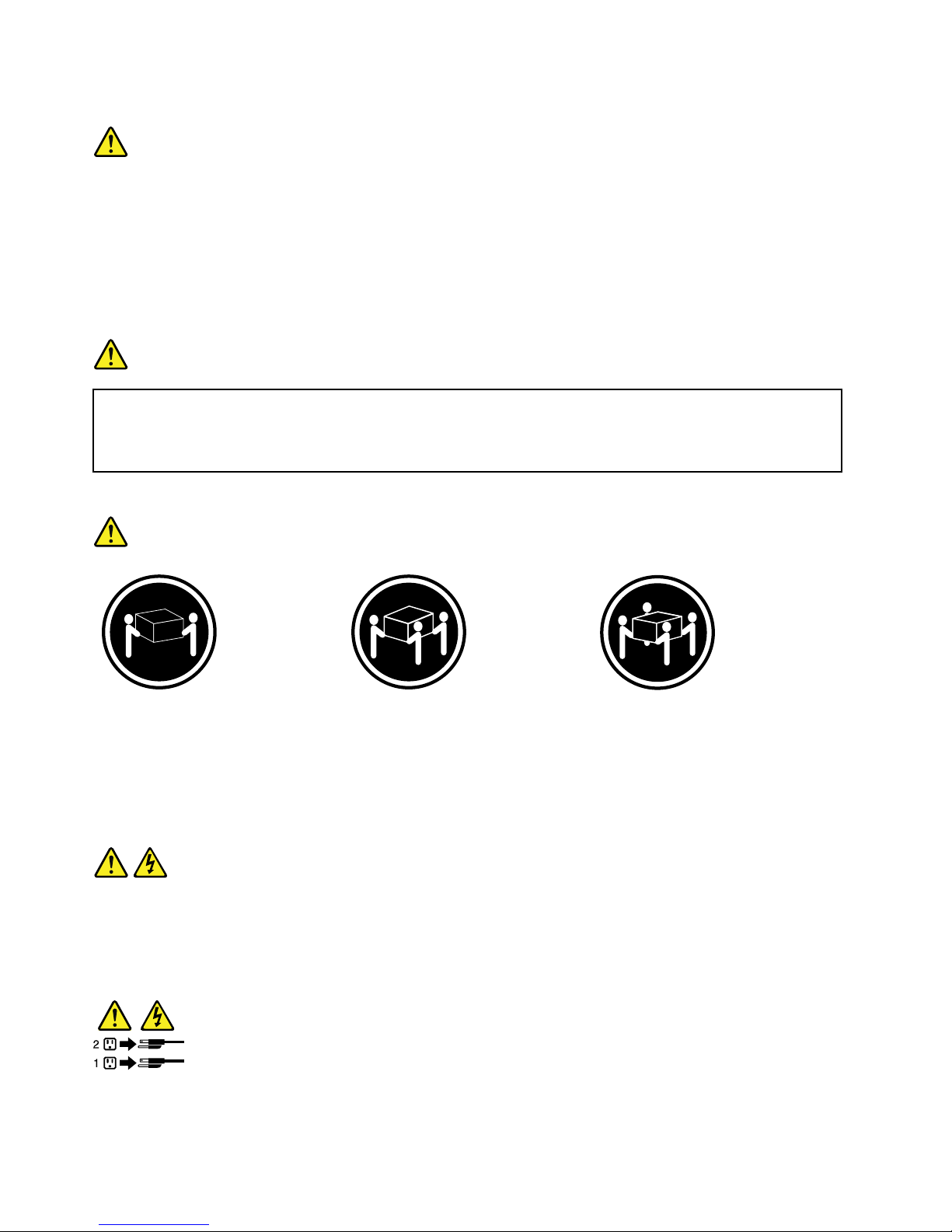
≥18kg(39.7lb)≥32kg(70.5lb)≥55kg(121.2lb)
<32kg(70.5lb)<55kg(121.2lb)<100kg(220.5lb)
CAUTION:
Usesafepracticeswhenlifting.
Statement5
CAUTION:
Thepowercontrolbuttononthedeviceandthepowerswitchonthepowersupplydonotturnoff
theelectricalcurrentsuppliedtothedevice.Thedevicealsomighthavemorethanonepower
cord.Toremoveallelectricalcurrentfromthedevice,ensurethatallpowercordsaredisconnected
fromthepowersource.
viThinkServerUserGuide
Page 9
Statement6
CAUTION:
Ifyouinstallastrain-reliefbracketoptionovertheendofthepowercordthatisconnectedtothe
device,youmustconnecttheotherendofthepowercordtoaneasilyaccessiblepowersource.
Statement7
CAUTION:
Ifthedevicehasdoors,besuretoremoveorsecurethedoorsbeforemovingorliftingthedeviceto
avoidpersonalinjury.Thedoorswillnotsupporttheweightofthedevice.
Statement8
CAUTION:
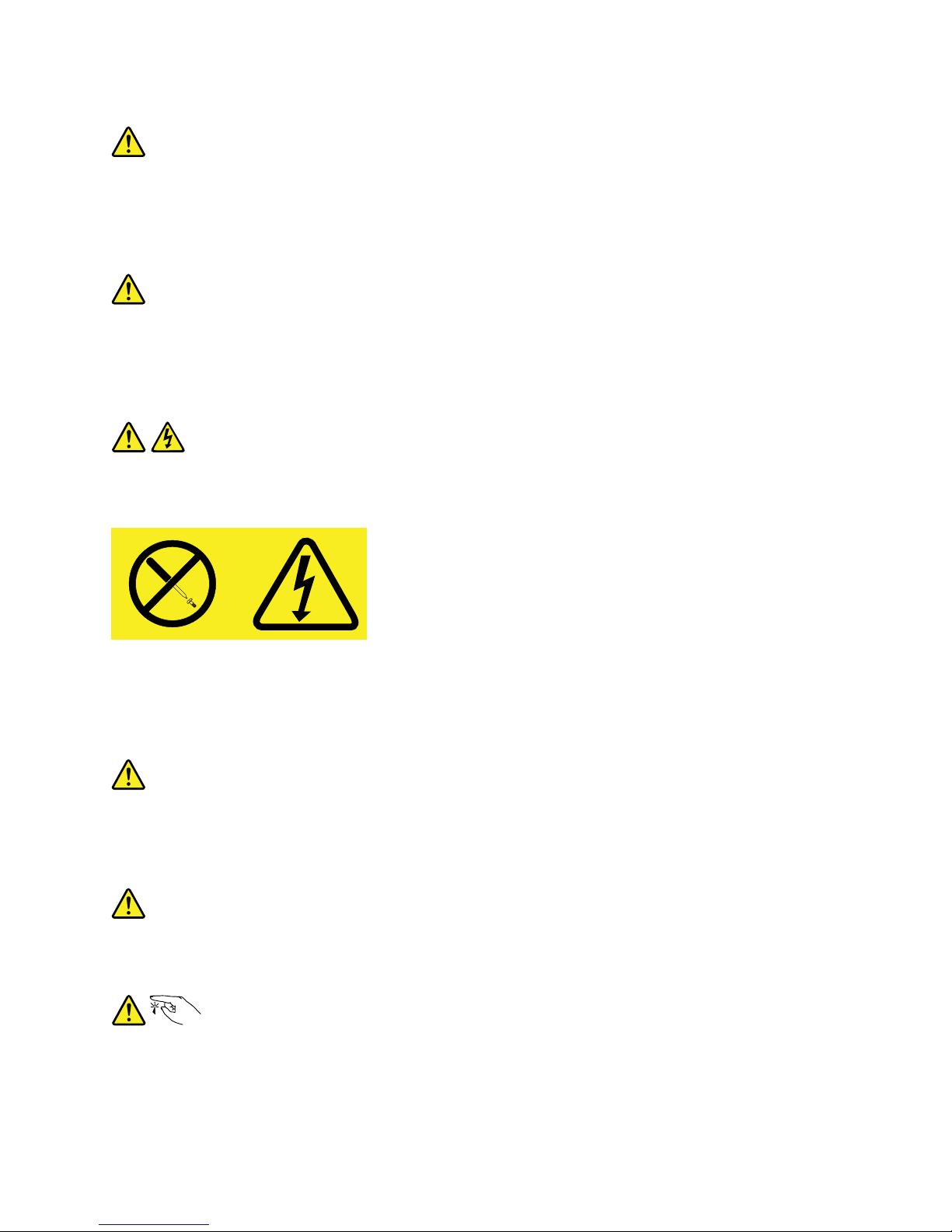
Neverremovethecoveronapowersupplyoranypartthathasthefollowinglabelattached.
Hazardousvoltage,current,andenergylevelsarepresentinsideanycomponentthathasthislabel
attached.Therearenoserviceablepartsinsidethesecomponents.Ifyoususpectaproblemwith
oneoftheseparts,contactaservicetechnician.
Statement9
CAUTION:
Toavoidpersonalinjury,disconnectthehot-swapfancablesbeforeremovingthefanfromthedevice.
Statement10
CAUTION:
Thefollowinglabelindicatessharpedges,corners,orjointsnearby.
©CopyrightLenovo2011
vii
Page 10
Statement11
CAUTION:
Thefollowinglabelindicatesahotsurfacenearby.
Statement12
DANGER
Overloadingabranchcircuitispotentiallyarehazardandashockhazardundercertainconditions.Toavoid
thesehazards,ensurethatyoursystemelectricalrequirementsdonotexceedbranchcircuitprotection
requirements.Refertotheinformationthatisprovidedwithyourdeviceforelectricalspecications.
Statement13
CAUTION:
Makesurethattherackissecuredproperlytoavoidtippingwhentheserverunitisextended.
Statement14
CAUTION:
SomeaccessoryoroptionboardoutputsexceedClass2orlimitedpowersourcelimitsandmustbe
installedwithappropriateinterconnectingcablinginaccordancewiththenationalelectriccode.
Statement15
CAUTION:
Thepower-controlbuttononthedevicedoesnotturnofftheelectricalcurrentsuppliedtothe
device.Thedevicealsomighthavemorethanoneconnectiontodcpower.T oremoveallelectrical
currentfromthedevice,ensurethatallconnectionstodcpoweraredisconnectedatthedcpower
inputterminals.
viiiThinkServerUserGuide
Page 11
Statement16
CAUTION:
Toreducetheriskofelectricshockorenergyhazards:
•Thisequipmentmustbeinstalledbytrainedservicepersonnelinarestricted-accesslocation,as
denedbytheNECandthelatesteditionofIEC60950,TheStandardforSafetyofInformation
TechnologyEquipment.
•Connecttheequipmenttoareliablygroundedsafetyextralowvoltage(SELV)source.AnSELV
sourceisasecondarycircuitthatisdesignedsothatnormalandsinglefaultconditionsdonot
causethevoltagestoexceedasafelevel(60Vdirectcurrent).
•Thebranchcircuitovercurrentprotectionmustberatedinaccordancewithlocalbuildingcodes.
•Use16AmericanWireGauge(AWG)or1.3mm
2
copperconductoronly,notexceeding3meters
inlength.
•T orquethewiring-terminalscrewsto12inch-pounds(1.4newton-meters).
•Incorporateareadilyavailableapprovedandrateddisconnectdeviceintheeldwiring.
Statement17
CAUTION:
ThisproductcontainsaClass1Mlaser.Donotviewdirectlywithopticalinstruments.
Statement18
CAUTION:
Donotplaceanyobjectontopofrack-mounteddevices.
Statement19
CAUTION:
Hazardousmovingparts.Keepngersandotherbodypartsaway.
©CopyrightLenovo2011
ix
Page 12

Statement20
CAUTION:
Thebatteryisalithiumionbattery.T oavoidpossibleexplosion,donotburnthebattery.Exchangeit
onlywiththeLenovo-approvedpart.Recycleordiscardthebatteryasinstructedbylocalregulations.
xThinkServerUserGuide
Page 13

Chapter1.Generalinformation
Thischapterprovidessomegeneralinformationaboutyourproduct.
Thischaptercontainsthefollowingitems:
•“Introduction”onpage1
•“Serverdocumentation”onpage2
Introduction
ThisuserguideforyourLenovo
®
ThinkServer
®
productcontainsinformationabouttheserverfeatures,
specications,componentlocations,congurationinstructions,hardwarereplacementprocedures,and
basictroubleshootinganddiagnostics.
YourservercomeswithadocumentationDVDthatcontainsvariousserverdocumentstohelpyouuseand
maintaintheserver.Meanwhile,yourservercomeswithaThinkServerEasyStartupDVDthatprovidesa
convenientsolutionforconguringtheserverandinstallinganoperatingsystem.
TheLenovoLimitedWarranty(LLW)containsthewarrantytermsthatapplytotheproductyoupurchasedfrom
Lenovo.ReadtheLLWonthedocumentationDVDthatcomeswithyourserver.Aprintablegenericversion
ofthelatestLLWisalsoavailableinmorethan30languagesathttp://www.lenovo.com/warranty/llw_01.If
youcannotobtaintheLLWthroughthedocumentationDVDorLenovoWebsite,contactyourlocalLenovo
ofceorresellertoobtainaprintedversionoftheLLW,freeofcharge.
Forwarrantyservice,consulttheworldwideLenovoSupporttelephonelist.Telephonenumbersaresubject
tochangewithoutnotice.Themostup-to-datetelephonelistforLenovoSupportisalwaysavailableonthe
Websiteathttp://www.lenovo.com/support/phone.Ifthetelephonenumberforyourcountryorregionisnot
listed,contactyourLenovoresellerorLenovomarketingrepresentative.
Toobtainthemostup-to-dateinformationabouttheserver,goto:
http://www.lenovo.com/thinkserver
LenovomaintainspagesontheWorldWideWebwhereyoucangetthelatesttechnicalinformationand
downloaddocumentationordevicedriversandupdates.ToaccesstheLenovoSupportWebsite,goto:
http://www.lenovo.com/support
©CopyrightLenovo2011
1
Page 14

Recordinformationaboutyourserverinthefollowingtable.Y ouwillneedtheinformationifyoueverneed
tohaveyourserverserviced.
Forwheretondtheproductinformationlabelonthechassis,see“Machinetype,model,andserialnumber
label”onpage13.
Productname
______________________________________________
Machinetypeandmodel(MT-M)
______________________________________________
Serialnumber(S/N)
______________________________________________
Dateofpurchase
______________________________________________
Youcanregisteryourserverbyfollowingtheinstructionsat:
http://www.lenovo.com/register
Youwillreceivethefollowingbenetsafterregisteringyourserver:
•Fasterservicewhenyoucallforhelp
•Automaticnoticationoffreesoftwareandspecialpromotionaloffers
Serverdocumentation
Thistopicprovidesgeneraldescriptionsofthevariousdocumentationforyourserverandinstructionson
howtoobtainallthedocumentation.
Printeddocuments
Thefollowingdocumentsareprintedoutandcontainedinyourserverpackage.
•ReadMeFirst
Thisisamultilingualdocumentyoushouldreadrst.Thisdocumentguidesyoutoreadthecomplete
warranty,support,andsafetyinformationonthedocumentationDVDthatcomeswithyourserverbefore
usingtheproduct.Thisdocumentalsoprovidesinformationabouthowtondthemostup-to-date
informationontheLenovoSupportWebsite.
•ImportantNotices
Thisdocumentincludessafetyandlegalnoticesthatyoushouldreadandunderstandbeforeusing
theserver.
DocumentationDVD
ThedocumentationDVD,whichcomeswithyourserver,containsvariousdocumentsforyourserverin
PortableDocumentFormat(PDF).Toviewthedocumentation,youneedtohavetheAdobeReaderprogram
installed.YoucandownloadthedesiredlanguageversionofthelatestAdobeReaderprogramfromthe
AdobeWebsiteat:
http://www.adobe.com
Note:LenovomaintainspagesontheWorldWideWebwhereyoucangetthelatesttechnicalinformation
anddownloaddocumentationordevicedriversandupdates.Someinformationinthedocumentsonthe
2ThinkServerUserGuide
Page 15

documentationDVDmightchangewithoutnoticeaftertherstreleaseoftheDVD.Youcanalwaysobtainall
themostup-to-datedocumentationforyourserverfromtheLenovoWebsiteat:
http://www.lenovo.com/ThinkServerUserGuides
ThefollowingdocumentsareonthedocumentationDVDthatcomeswithyourserver:
•SafetyInformation
Thisisamultilingualdocumentthatincludesallthesafetystatementsforyourproductinmorethan30
languages.Besuretoreadandunderstandallthesafetystatementsbeforeusingtheproduct.
•WarrantyandSupportInformation
ThisdocumentincludestheLenovowarrantystatement,CustomerReplaceableUnits(CRUs)information,
andinformationabouthowtocontactLenovoSupport.
•UserGuide
Thisdocumentprovidesdetailedinformationtohelpyougetfamiliarwithyourserverandhelpyouuse,
congure,andmaintainyourserver.
•RemoteManagementModuleUserGuide
ThisdocumentprovidesinformationtohelpyouusetheintegratedKeyboard,Video,andMouse(iKVM)
functionforserverremotemanagement.ThisdocumentisinEnglishonly.
Note:AThinkServeriKVMRemoteManagementModule(hereinafterreferredtoastheiKVMkey)is
requiredandthisoptionshouldbeinstalledontheiKVMkeyconnectoronthesystemboardtoenable
theiKVMfunction.
•MegaRAIDSASSoftwareUserGuide
ThisdocumentprovidesinformationaboutRedundantArrayofIndependentDisks(RAID)andhowto
usetheutilityprogramstocongure,monitor,andmaintainyourserverRAIDandrelateddevices.This
documentisinEnglishonly.
Note:RefertothisdocumentforhardwareRAIDinformationifyouhavearequiredRAIDcardinstalledin
theserver.See“InstallingorremovingtheRAIDcard”onpage98
.Forinformationabouttheonboard
SATAsoftwareRAID,see“ConguringtheonboardSATAsoftwareRAID”onpage75
.
Documentfortrainedservicepersonnelonly
ThefollowingdocumentisintendedfortrainedservicepersonnelofLenovoandisonlyavailableinEnglish
ontheLenovoWebsiteat:
http://www.lenovo.com/ThinkServerUserGuides
HardwareMaintenanceManual
Thisdocumentprovidesdiagnosticinformation,partslisting,andreplacementproceduresforalleld
replaceableunits(FRUs,partsreplacedbytrainedservicepersonnel)aswellasallCRUs.
Chapter1.Generalinformation3
Page 16

4ThinkServerUserGuide
Page 17

Chapter2.Serversetuproadmap
Thischapterprovidesageneralroadmaptoguideyouthroughsettingupyourserver.
Theserversetupprocedurevariesdependingonthecongurationoftheserverwhenitwasdelivered.In
somecases,theserverisfullyconguredandyoujustneedtoconnecttheservertothenetworkandan
acpowersource,andthenyoucanturnontheserver.Inothercases,theserverneedstohavehardware
featuresinstalled,requireshardwareandrmwareconguration,andrequiresanoperatingsystemto
beinstalled.
Thegeneralprocedureforsettingupyourserveris:
1.Unpacktheserverpackage.See“Serverpackage”onpage7.
2.Installanyrequiredhardwareorserveroption.SeetherelatedtopicinChapter6“Installing,removing,
orreplacinghardware”onpage83
.
3.ConnecttheEthernetcableandpowercord(s)totheserver.See“Rearviewoftheserver”onpage
19tolocatetheconnectors.
4.T urnontheservertoverifyoperation.See“Turningontheserver”onpage53.
5.ReviewtheUniedExtensibleFirmwareInterface(UEFI)settingsandcustomizeasneeded.See“Using
theSetupUtilityprogram”onpage55
.
6.CongureRAIDandinstalltheoperatingsystemandbasicdrivers.See“UsingtheThinkServer
EasyStartupprogram”onpage69and“ConguringRAID”onpage71.
7.Installanyadditionaldriversneededforaddedfeatures.Refertotheinstructionsthatcomewiththe
hardwareoption.
8.CongureEthernetsettingsintheoperatingsystembyreferringtotheoperatingsystemhelp.Thisstep
isnotrequirediftheoperatingsystemwasinstalledusingtheThinkServerEasyStartupprogram.
9.Checkforrmwareanddriverupdates.See“Updatingthermware”onpage81.
10.Installotherapplications.Refertothedocumentationthatcomeswiththeapplicationsthatyouwantto
install.
©CopyrightLenovo2011
5
Page 18

6ThinkServerUserGuide
Page 19
Chapter3.Productoverview
Thischapterprovidesinformationabouttheserverpackage,features,specications,softwareprograms,
andcomponentlocations.
Thischaptercontainsthefollowingitems:
•“Serverpackage”onpage7
•“Features”onpage7
•“Specications”onpage12
•“Software”onpage12
•“Locations”onpage13
Serverpackage
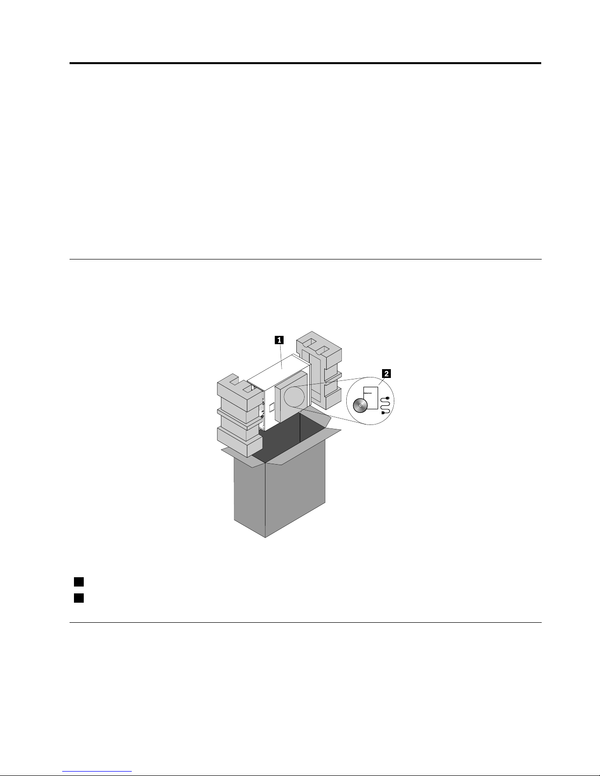
Theserverpackageincludestheserver,powercord(s),printeddocumentation,documentationDVD,and
softwaremedia.
Figure1.Serverpackage
1Server
2Materialbox,includingpowercord(s),printeddocumentation,documentationDVD,andsoftwaremedia
Features
Thistopicprovidesgeneralinformationabouttheserverfeaturesforavarietyofmodels.Dependingonyour
specicmodel,somefeaturesmightvaryornotbeavailable.Forinformationaboutyourspecicmodel,use
theSetupUtilityprogram.See“ViewinginformationintheSetupUtilityprogram”onpage55.
©CopyrightLenovo2011
7
Page 20

Microprocessor
Yourservercomeswithoneofthefollowingmicroprocessors(internalcachesizevariesbymodel):
•Intel
®
Xeon
®
quad-coremicroprocessor
•IntelXeondual-coremicroprocessor
•IntelCore™i3microprocessor
ForalistoftheThinkServermicroprocessoroptions,gotohttp://www.lenovo.com/thinkserver.Clickthe
ProductstabandthenclickOptions➙ThinkServerProcessorstoviewtheinformation.
Memory
Yourserversupportsuptofourdoubledatarate3unbuffereddualinlinememorymodules(DDR3UDIMMs)
withErrorCheckingandCorrecting(ECC)technology.
•Supports2GBand4GB1333MHzDDR3UDIMMs
•Single-rankordual-rank
•Minimumsystemmemory:2GB(onlyone2GBmemorymoduleinstalledintheDIMMA2slot)
•Maximumsystemmemory:16GB(one4GBmemorymoduleinstalledineachofthefourmemoryslots)
Formoreinformation,see“Systemboardcomponents”onpage42and“Memorymoduleinstallation
rules”onpage90.
Powersupply
Yourservercomeswithoneofthefollowingpowersupplycongurations:
•Onescrew-secured,non-hot-swap400-wattpowersupply(80PlusBronzeCompliantanduniversalinput)
•Oneortwohot-swap450-wattredundantpowersupplymodules(80PlusGoldCompliantanduniversal
input)
Fans
Youservercomeswiththefollowingfanstoprovidepropersystemcoolingandairow:
•Oneheatsinkandfanassembly
•Oneortwofrontsystemfansdependingonthemodel
•Onerearsystemfan
8ThinkServerUserGuide
Page 21

Internaldrives
Internaldrivesaredevicesthatyourserverusestoreadandstoredata.Theinternaldrivessupported
byyourservervarybymodel.
•Harddiskdrive
–Fivetoeight3.5-inchhot-swapSerialAdvancedTechnologyAttachment(SATA)orSerialAttached
SCSI(SAS)harddiskdrives(SCSIistheacronymforSmallComputerSystemInterface)
–Uptoeight2.5-inchhot-swapSASharddiskdrives
–Uptofour3.5-inchhot-swapSATAorSASharddiskdrives
–Uptofour3.5-inchnon-hot-swapSATAharddiskdrives
Note:ForservermodelswithmorethanfourharddiskdrivesormodelsthatuseSASharddiskdrives,
theremustbearequiredRAIDcardinstalled.See“RAIDcard”onpage33
.
•Opticaldrive
–Uptotwo5.25-inchSATAopticaldrives(DVD-ROMorDVDBurner/CD-RWRambo8)
–Theloweropticaldrivebayisinstalledwitha5.25-inchSATAopticaldrive(DVD-ROMorDVDBurner/
CD-RWRambo8).TheupperopticaldrivebayisforaRemovableDiskTechnology(RDX)Universal
SerialBus(USB)drivebundle.
Forthelocationinformationabouttheinternaldrivesordrivebays,see“Servercomponents”onpage
25
.ForinformationabouttheRDXUSBdrivebundleandinstructionsonhowtoinstallit,refertothe
documentationthatcomeswiththeRDXUSBdrivebundle.Inyourserver,theP6powerconnectorofthe
powersupplyisfortheRDXUSBdrivebundle.YoucanpurchasethisoptiondirectlyfromLenovo.The
optionnameisLenovoRemovableDiskT echnology(RDX)USBDriveBundle.TheRDXtechnologycombines
thecharacteristicsoftapebackupwithdiskstoragetohelpyouprotectandarchivedata.
Expansionslots
Theserverhasfourexpansionslotsonthesystemboard.Fordetailedinformation,see“Systemboard
components”onpage42.
Input/Output(I/O)features
•OneVideoGraphicsArray(VGA)DB-15connectorontherearpanel
•SixUSB2.0connectors(twoonthefrontpanelandfourontherearpanel)
•TwoRJ-45Ethernetconnectorsontherearpanel
•Twoserialconnectors(onefully-functionalserialconnectorontherearpanelandoneinternalserial
connectoronthesystemboardforoptionaluse)
Forthelocationinformationabouttheconnectors,refertotherelatedtopicin“Locations”onpage13
.
Videosubsystem
AnintegratedgraphicscontrollerintheBaseboardManagementController(BMC)chiponthesystemboard
tosupportaVGADB-15connectorontherearpanelforconnectingvideodevices
Ethernetconnectivity
TheservercomeswithanintegratedIntelGigabitEthernetcontrolleraswellasanEthernetphysicallayer
(PHY)oftheOpenSystemsInterconnectionmodel(OSImodel).Theyprovidetheserverwiththeability
tosupporttwoEthernetconnectorsontherearpanelwith10Mbps,100Mbps,or1000Mbpsnetwork
connectivity.Formoreinformation,see“Rearviewoftheserver”onpage19
.
Chapter3.Productoverview9
Page 22

Reliability,availability,andserviceability
Reliability,availability,andserviceability(hereinafterreferredtoasRAS)arethreeimportantserverdesign
features.TheRASfeatureshelpyoutoensuretheintegrityofthedatastoredontheserver,theavailabilityof
theserverwhenyouneedit,andtheeasewithwhichyoucandiagnoseandcorrectproblems.
YourserverhasthefollowingRASfeatures:
•Securityfeatures
–Serverlocks(see“Serverlocks”onpage22)
–Administratorpasswordanduserpasswordtohelpprotectunauthorizedaccesstotheserver(see
“Usingpasswords”onpage65)
–TrustedPlatformModule(TPM)connectoronthesystemboardforaTPMmodule,whichisasecurity
chip,tohelpprotectyourserverandstrengthenserversecurity
Note:TheTPMmoduleisonlyavailableinsomemodels.
–Remotemonitoringorcontrolbyanadministratortoprovideprotectionorhelp
–Hot-swapredundantpowersupplymodulestohelpyouavoidsignicantinterruptiontotheoperation
ofthesystemwhenapowersupplymodulefails(availableinsomemodels)
•Basicsystemmanagementfeatures
–Abilitytostorethepower-onself-test(POST)hardwaretestresults
–BIOSSetupUtilityprogram
TheBIOSSetupUtilityprogramhelpsyouviewtheserverinformationandconguretheserverinthe
pre-operatingsystemenvironment.See“UsingtheSetupUtilityprogram”onpage55
.
–BMCandIntelligentPlatformManagementInterface(IPMI)2.0
ThesystemboardplatformmanagementsubsystemisbasedontheintegratedBMCfeatures.The
BMCisamanagementchipthatisintegratedonthesystemboardofyourserver.WiththeBMCchip,
nomatterwhatconditiontheserveroperatingsystemisinandnomatteriftheserverisonoroff,aslong
astheserverisconnectedtonetworkandanacpowersource,theinteractionwiththeBMCcontrolled
serverscanbeachievedthroughsystemnetwork.Theusercanobtaintheserverhardwarehealth
informationandsystemeventlog(SEL),andisabletoconducttheoperationsincludingturningonor
offtheserver,restartingtheserver,lockingthepowerswitchonthefrontpanel,andsoon.Thispartof
theservermanagementisindependentoftheoperatingsystemandiscalledout-of-bandmanagement.
ThesystemboardplatformmanagementsubsystemconsistsoftheintegratedBMC,communication
buses,sensors,BasicInputOutputSystem(BIOS),andservermanagementrmware.Itisresponsible
forerrormanagementandreporting,systempowercontrol,thermalmonitoring,systemfancontrol,
andothermanagementfeatures.TheBMCprovidessystemmanagementandmonitoringfeatures
basedontheIPMI2.0specication.IPMIhelpslowertheoverallcostsofservermanagement.Youcan
ndmoreinformationaboutIPMI2.0fromtheWebsiteofIntel.TheBMCalsosupportssomenon-IPMI
features,suchastheDynamicHostCongurationProtocol(DHCP)andthePlatformEnvironment
ControlInterface(PECI),toprovidemoresystemmanagementfunctions.
RefertotheRemoteManagementModuleUserGuideonthedocumentationDVDthatcomeswithyour
serverformoreinformation.
–Hot-swapfeature
Somemodelssupporthot-swapharddiskdrivesandorhot-swapredundantpowersupplymodules.
Withthehot-swapfeature,youcaninstall,remove,orreplaceharddiskdrivesorafailingpowersupply
modulewithoutturningofftheserver.
10ThinkServerUserGuide
Page 23

–PrebootExecutionEnvironment(PXE)
TheIntelPXEtechnologyenablesyoutobootyourcomputers,loadanoperatingsystem,ordeploy
executableimagesfromaremoteserverbyusinganetworkinterface.Theoperationcanbedone
independentlyoflocaldatastoragedevices(suchasharddiskdrives)orinstalledoperatingsystems.
–RedundantArrayofIndependentDisks(RAID)
YourserversupportsonboardSATAsoftwareRAIDandadvancedSATA/SAShardwareRAID
congurationsifyouhavearequiredRAIDcardinstalled.Fordetailedinformation,see“Conguring
RAID”onpage71.
–Statuslight-emittingdiodes(LEDs)anddiagnosticLEDs
FormoreinformationabouttheLEDsforyourserver,refertotherelatedtopicsin“Locations”on
page13.
–ThinkServerEasyStartupprogramandThinkServerEasyUpdateFirmwareUpdaterprogram
Formoreinformationaboutthesoftwareprograms,see“Software”onpage12.
–WakeonLAN
WhentheWakeonLANfeatureisenabledonacomputerthatisconnectedtoalocalareanetwork
(LAN),anetworkadministratorcanremotelyturnonorwakeupthecomputerfromamanagement
consoleusingremotenetworkmanagementsoftware.Besides,manyotherfunctions,suchasdata
transferandsoftwareupdates,canbeperformedremotelywithoutremoteattendanceandcanbedone
afternormalworkinghoursandonweekendstosavetimeandincreaseproductivity.
•Advancedsystemmanagementfeatures
TheBMCrmwaresupportsthefollowingadvancedsystemmanagementfeatures:
Note:TheadvancedsystemmanagementfeaturesareonlyavailablewhentheBMCdetectsthepresence
ofanintegratedkeyboard,video,andmouse(iKVM)key.TheiKVMkeyisaremotemanagementmodule.
YoucanpurchaseaniKVMkeyfromLenovoandinstallitontheiKVMkeyconnectoronthesystemboard
ofyourservertoenabletheiKVMfunctionandactivatetheadvancedsystemmanagementfeatures.
–iKVMredirection
TheBMCrmwaresupportsiKVMredirectionoverLAN.Thisfeatureisavailableremotelyfromthe
embeddedWebserver.Theremotemanagementmodulecandigitizeandcompressthecollected
keyboard,video,andmousesignalsfromthehostsystemandthensendthemtotheremoteconsole.
Meanwhile,itiseasilyaccessiblebyremoteKVMandcontrollablethroughLANorInternet.Fordetailed
information,refertotheRemoteManagementModuleUserGuideonthedocumentationDVDthat
comeswithyourserver.
–Mediaredirection
TheembeddedWebserverprovidesaJavaJNLPtoenabletheremotemediaredirection.Thisisused
inconjunctionwiththeremoteKVMfeatureorasastandaloneapplet.
Themediaredirectionfeatureisintendedtoenablesystemadministratorsoruserstomountaremote
opticaldrive,oppydrive,orUSBashdiskasaUSBdevicetotheserver.Oncemounted,theremote
devicefunctionsasalocaldevicetotheserver,enablingsystemadministratorsoruserstobootthe
serverandinstallsoftware(includingoperatingsystems),copyles,updatetheBIOSfromthisdevice.
–WebServicesforManagement(WS-MAN)
TheBMCrmwaresupportstheWS-MANspecication.
–LocalDirectoryAuthenticationProtocol(LDAP)
TheBMCrmwaresupportstheLDAPforuserauthentication.
Note:TheIPMIusers,passwords,andsessionsarenotsupportedoverLDAP.
Chapter3.Productoverview11
Page 24

–EmbeddedWebserver
TheBMCprovidesanembeddedWebserverforout-of-bandmanagement.Theuserauthenticationis
handledbyIPMIusernamesandpasswords.Formoreinformation,refertotheRemoteManagement
ModuleUserGuideonthedocumentationDVDthatcomeswithyourserver.
Specications
Thistopicliststhephysicalspecicationsforyourserver.
Dimensions
Width:195mm(7.68inches)
Height:430mm(16.93inches)withoutfootstands;445mm(17.52inches)withfootstands
Depth:595mm(23.43inches)includingthefrontbezel
Weight
Theproductweightvariesdependingondifferentsystemcongurations.
Rangeofproductweightwithoutpackage:19kg(41.89lb)to28kg(61.73lb)
Rangeofproductpackageweight:2.8kg(6.17lb)to3.5kg(7.72lb)
Environment
•Airtemperature:
Operating:10°Cto35°C(50°Fto95°F)
Storage:-40°Cto70°C(-40°Fto158°F)inoriginalshippingpackage
•Altitude:0to3048m(0to10000ft)
•Humidity:
Operating:8%to80%(non-condensing)
Storage:8%to90%(non-condensing)
Electricalinput
Universalinput:
Minimum:90Vac
Maximum:264Vac
Inputfrequencyrange:47to63Hz
Software
Thistopicprovidesinformationaboutthesoftwareprogramsthatyoucanusetohelpyousetup,use,
andmaintaintheserver.
ThinkServerEasyStartup
TheThinkServerEasyStartupprogramsimpliestheprocessofconguringRAIDandinstallingsupported
Microsoft
®
Windows
®
andLinuxoperatingsystemsanddevicedriversonyourserver.Thisprogramis
providedwithyourserveronaself-starting(bootable)ThinkServerEasyStartupDVD.Theuserguidefor
theprogramisalsoontheDVDandcanbeaccesseddirectlyfromtheprograminterface.Fordetailed
information,see“UsingtheThinkServerEasyStartupprogram”onpage69
.
12ThinkServerUserGuide
Page 25

ThinkServerEasyUpdateFirmwareUpdater
TheThinkServerEasyUpdateFirmwareUpdaterprogram(hereinafterreferredtoasFirmwareUpdater)
enablesyoutomaintainyourserverrmwareup-to-dateandhelpsyouavoidunnecessaryserveroutages.
TheFirmwareUpdaterprogramisprovidedontheLenovoSupportWebsite.Formoreinformationabout
downloadingandusingtheFirmwareUpdaterprogram,see“Updatingthermware”onpage81
.
BIOSandBMCrmwareupdateutility
TheBIOSandBMCrmwarekeepsupdatingaftertheshipmentoftheserver.Lenovomaintainspages
ontheSupportWebsiteandprovidestheBIOSandBMCrmwareupdateutilitywithinstructionsfor
downloadtohelpyouupdatetheBIOSandBMCrmwareifneeded.Formoreinformation,see“Updatingor
recoveringtheBIOS”onpage67
andor“Updatingthermware”onpage81.
RAIDcongurationutilities
YourserversupportsonboardSATAsoftwareRAIDandadvancedSATA/SAShardwareRAIDcongurations
ifyouhavearequiredRAIDcardinstalled.Fordetailedinformation,see“ConguringRAID”onpage71.
PC-DoctorforDOS
ThePC-DoctorforDOSisadiagnostictoolthatyoucanusetotestandgatherinformationaboutyoursystem
inordertoensureyoursystemisworkingcorrectlyandresolveanyhardwareissues.Youcandownloadthe
latestversionofthisdiagnosticprogramfromhttp://www.lenovo.com/supportandcreateaself-starting
DOS-baseddiagnosticutilitythatyoucanusetodetectfailinghardwarecomponentsindependentlyofthe
operatingsystem.Formoreinformation,see“Usingthediagnosticprogram”onpage168
.
Locations
Thistopicprovidesinformationtohelpyoulocateyourservercomponents.
Machinetype,model,andserialnumberlabel
Thistopichelpsyoulocatethetwolabelsthatcontainthemachinetype,model,andserialnumber
informationforyourserver.Thetwolabelsarethesame.Oneisonthefrontbezelandtheotherison
thechassis.
Themachinetype,model,andserialnumberidentifyyourserver.WhenyoucontactLenovoforhelp,the
informationhelpssupporttechnicianstoidentifyyourserverandprovidefasterservice.
Chapter3.Productoverview13
Page 26
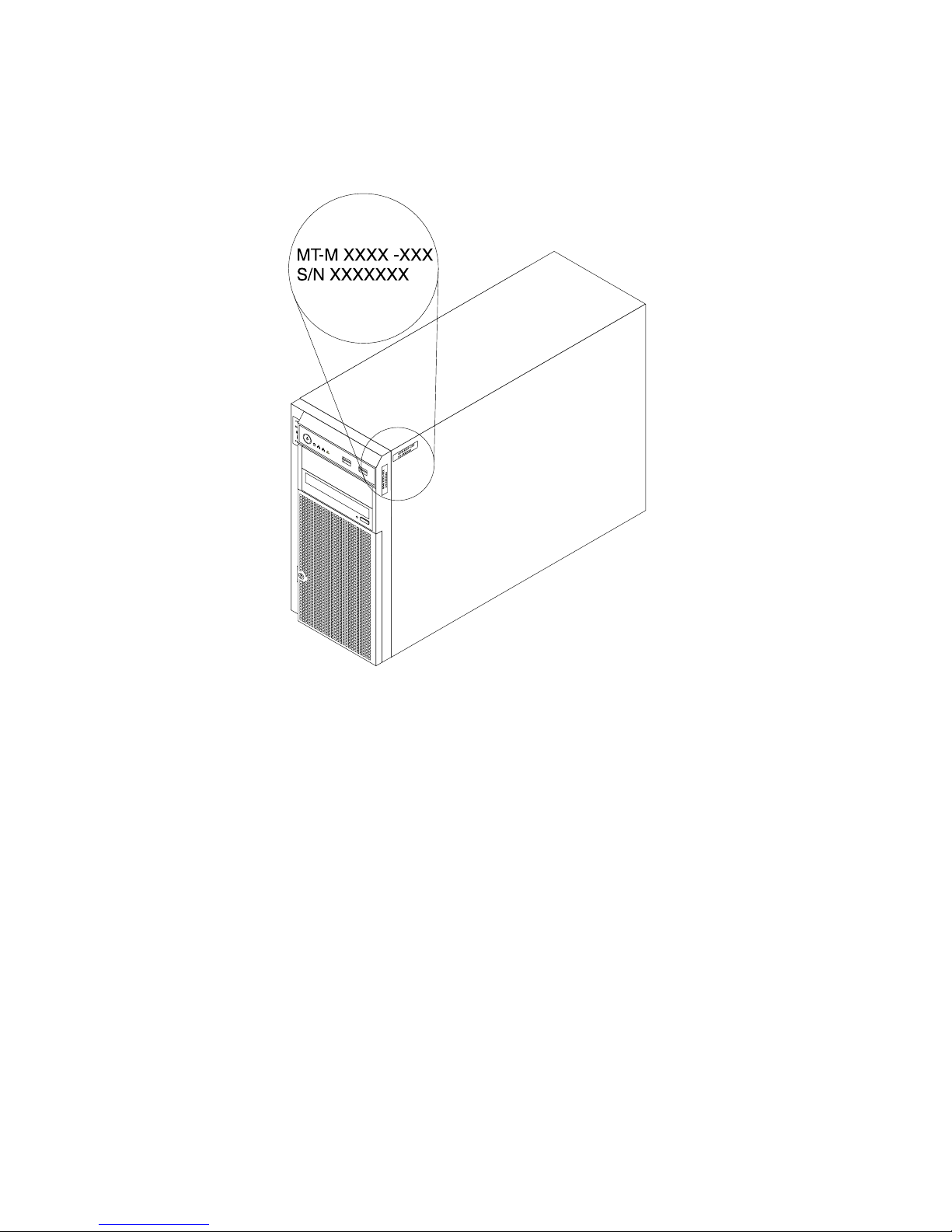
Thefollowingillustrationisasampleofthemachinetype,model,andserialnumberlabelsontheserver.
Note:Dependingonthemodeltype,yourservermightlookslightlydifferentfromtheillustrationinthistopic.
Figure2.Machinetype,model,andserialnumberlabels
14ThinkServerUserGuide
Page 27
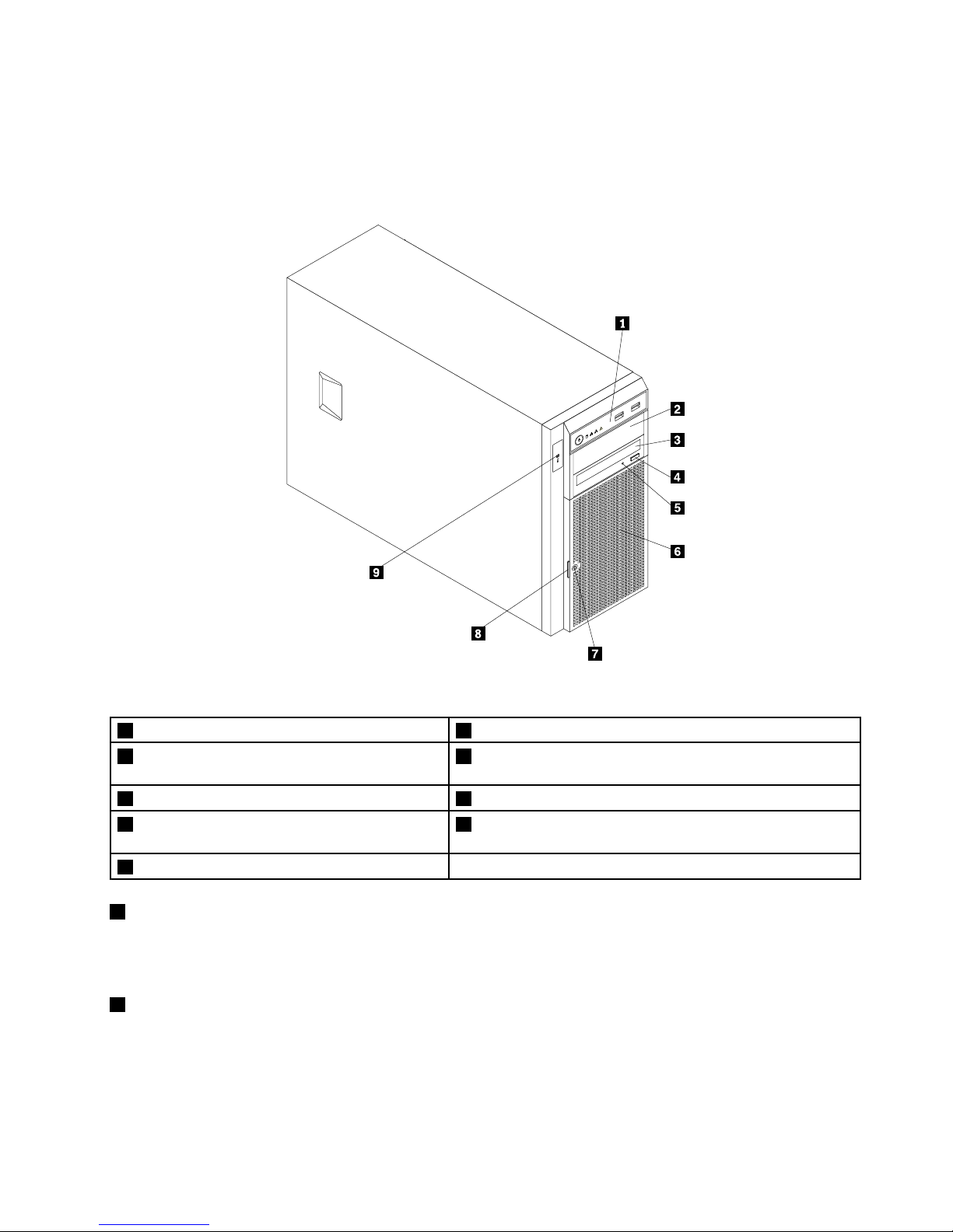
Frontviewoftheserver
Thistopicprovidesinformationtohelpyoulocatethepartsonthefrontoftheserver.
Thefollowingillustrationshowsthefrontviewoftheserver.
CPU
MEM
PSU
1
2
Figure3.Frontviewoftheserver
1Frontpanel6Frontdoor
2Opticaldrivebay2(withanopticaldriveinstalled
insomemodels)
7Frontdoorlock
3Opticaldrivebay1(withanopticaldriveinstalled)
8Frontdoorhandle
4Opticaldriveeject/closebutton9DoctorInsideTechnology(DIT)panel(availableinsome
models)
5OpticaldrivestatusLED
1Frontpanel
Fordetailedinformationaboutthecontrol,connectors,andstatusLEDsonthefrontpanel,see“Front
panel”onpage17.
2Opticaldrivebay2
The5.25-inchopticaldrivebay2isforasecondaryopticaldriveoraRDXUSBdrivebundle(serveroption).
Somemodelshaveasecondaryopticaldriveinstalled.
Chapter3.Productoverview15
Page 28
3Opticaldrivebay1
Yourservercomeswithanopticaldriveinstalledinthe5.25-inchopticaldrivebay1.
4Opticaldriveeject/closebutton
Pressthisbuttontoejectorclosetheopticaldrivewhentheserverpowerison.
5OpticaldrivestatusLED
TheopticaldrivestatusLEDisblinkingingreenwhentheopticaldriveisworkingorinthePOSTprocess.
6Frontdoor
7Frontdoorlock
Youcanlockthefrontdoortoprotecttheharddiskdrivecagesfromunauthorizedaccess.
8Frontdoorhandle
Thefrontdoorhandlehelpsyoutoopenthefrontdoor.
9DITpanel
TheDITpanelisonlyavailableinmodelsthatcomewithaDITmodule.Formoreinformation,see“DIT
module”onpage18.
16ThinkServerUserGuide
Page 29
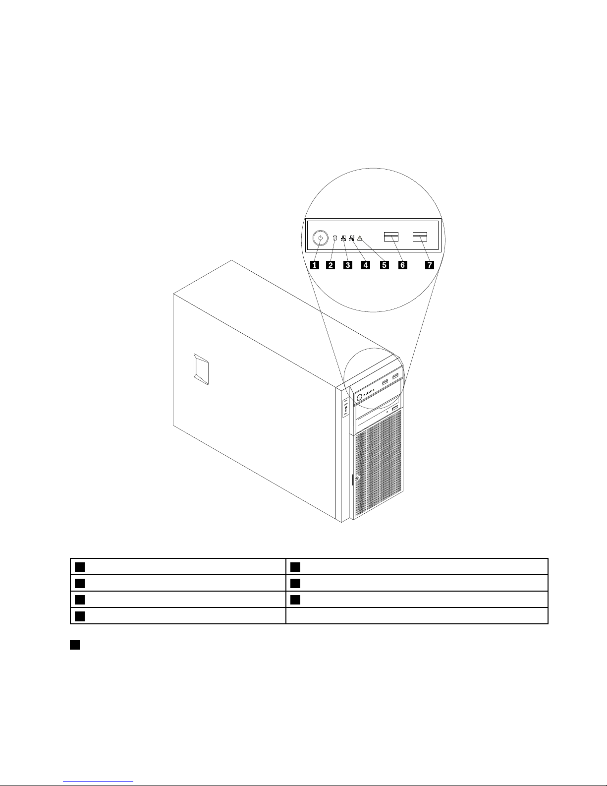
Frontpanel
Thistopicprovidesinformationtohelpyoulocatethecontrol,connectors,andLEDsonthefrontpanelof
theserver.
Thefollowingillustrationshowsthecontrol,connectors,andLEDsonthefrontpaneloftheserver.
Dependingonthemodel,yourservermightlookslightlydifferentfromthefollowingillustration.
Figure4.Frontpanel
1PowerswitchwithpowerstatusLED
5SystemstatusLED
2HarddiskdrivestatusLED
6FrontUSBconnector1
3NetworkInterfaceController(NIC)1statusLED7FrontUSBconnector2
4NIC2statusLED
1PowerswitchwithpowerstatusLED
Youcanpressthepowerswitchtoturnontheserverwhenyounishsettinguptheserver.Youcanalso
holdthepowerswitchforseveralsecondstoturnofftheserverifyoucannotturnofftheserverfromthe
operatingsystem.SeeChapter4“Turningonandturningofftheserver”onpage53
.ThepowerstatusLED
helpsyoutodeterminethecurrentpowerstatus.
Chapter3.Productoverview17
Page 30
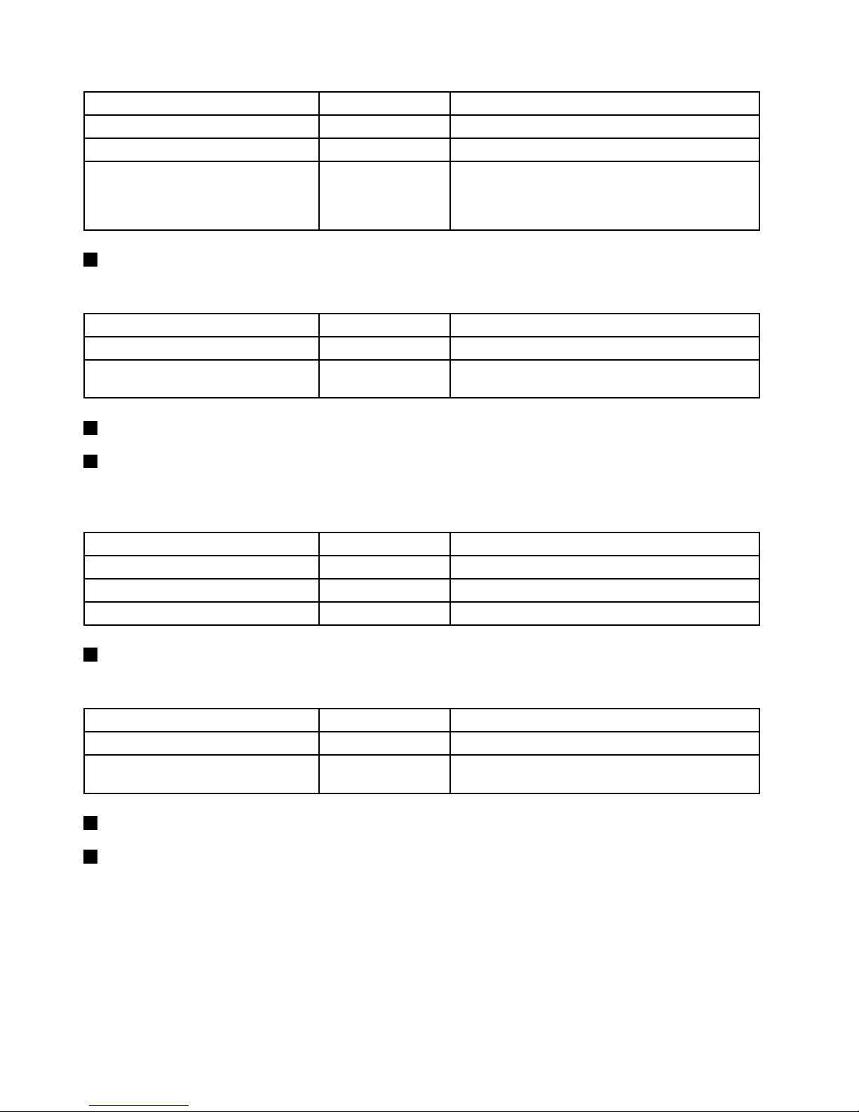
PowerstatusLED
Color
Description
OnGreen
Theserverison.
Off
None
Theserverisoff.
Blinking
GreenTheserverisinACPIS1mode,whichisalsoknown
asPowerOnSuspend(POS)mode.Inthismode,the
microprocessorisnotworkingwhileotherhardware
devicesarestillworking.
2HarddiskdrivestatusLED
TheharddiskdrivestatusLEDhelpsyoutodeterminethestatusoftheharddiskdriveactivity.
HarddiskdrivestatusLED
Color
Description
Off
NoneTheharddiskdriveisnotinuse.
Blinking
Green
Theharddiskdriveisactiveanddataisbeing
transferred.
3NIC1statusLED
4NIC2statusLED
ThetwoNICstatusLEDsindicatetheLANstatusfortheEthernetconnector1andEthernetconnector2
ontherearpaneloftheserver.
NICstatusLEDColor
Description
OnGreen
TheserverisconnectedtoaLAN.
Off
None
TheserverisdisconnectedfromaLAN.
Blinking
Green
TheLANisconnectedandactive.
5SystemstatusLED
ThesystemstatusLEDhelpsyoutodetermineifthereareanysystemerrors.
SystemstatusLEDColor
Description
On
AmberAsystemerrorhasoccurred.
Off
None
Theserverisoffortheserverisonandisworking
correctly.
6FrontUSBconnector1
7FrontUSBconnector2
UsedtoattachadevicethatrequiresaUSBconnector,suchasaUSBkeyboard,aUSBmouse,aUSB
scanner,oraUSBprinter.IfyouhavemorethansixUSBdevices,youcanpurchaseaUSBhub,which
youcanusetoconnectadditionalUSBdevices.
DITmodule
ThistopicprovidesinformationabouttheDITmoduleandthediagnosticLEDsonthepaneloftheDIT
module.
18ThinkServerUserGuide
Page 31
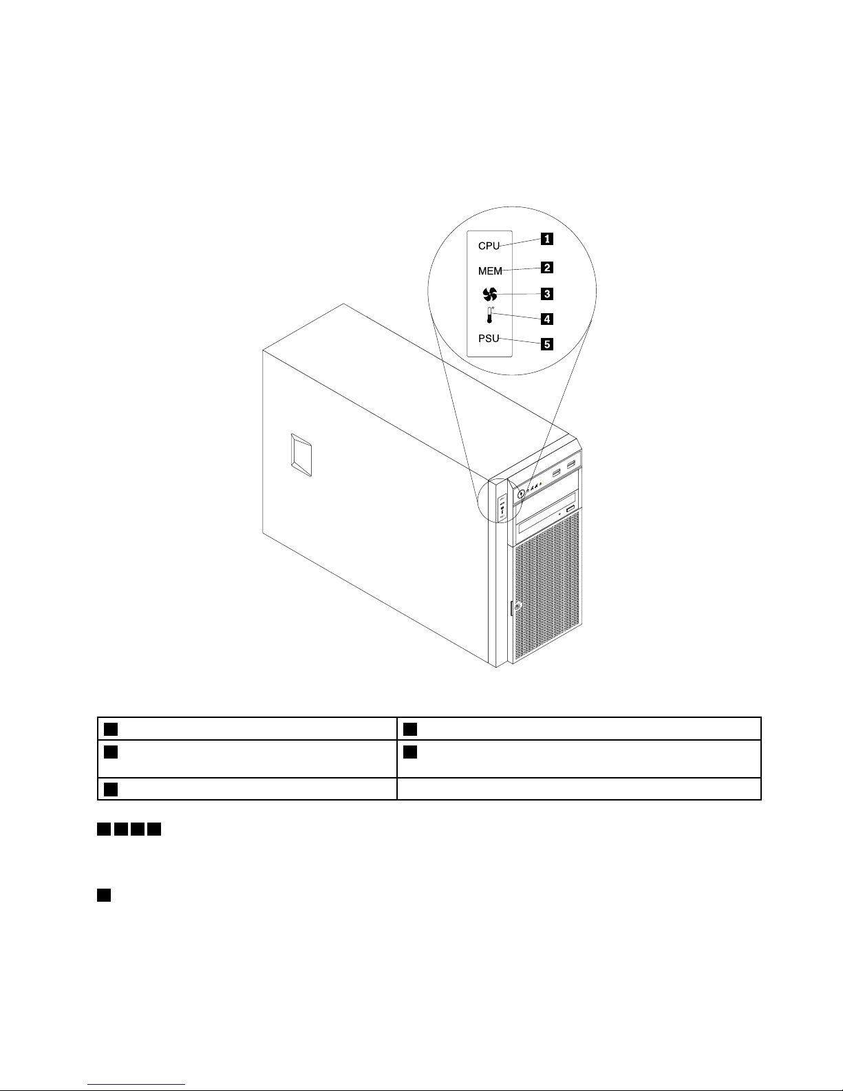
Note:TheDITmoduleisonlyavailableinsomemodels.
ThefollowingillustrationshowsthelocationoftheDITmoduleandthediagnosticLEDsontheDITpanelin
thefrontoftheserver.Dependingonthemodel,yourservermightlookslightlydifferentfromthefollowing
illustration.
Figure5.DITpanel
1MicroprocessorerrorLED4AmbienttemperatureoverlimitLED
2MemorymoduleerrorLED
5PowersupplyerrorLED(onlyavailableonmodelswith
redundantpowersupplymodules)
3FanerrorLED
1235ErrorLEDs
WhenoneoftheseerrorLEDsislit(orange),itindicatesthattheassociatedcomponenthasfailed.
4AmbienttemperatureoverlimitLED
WhenthisLEDislit(orange),itindicatesthattheambienttemperatureisover38°C(100.4°F).
Rearviewoftheserver
Thistopicprovidesinformationtohelpyoulocatetheconnectorsandcomponentsontherearofyourserver.
Chapter3.Productoverview19
Page 32
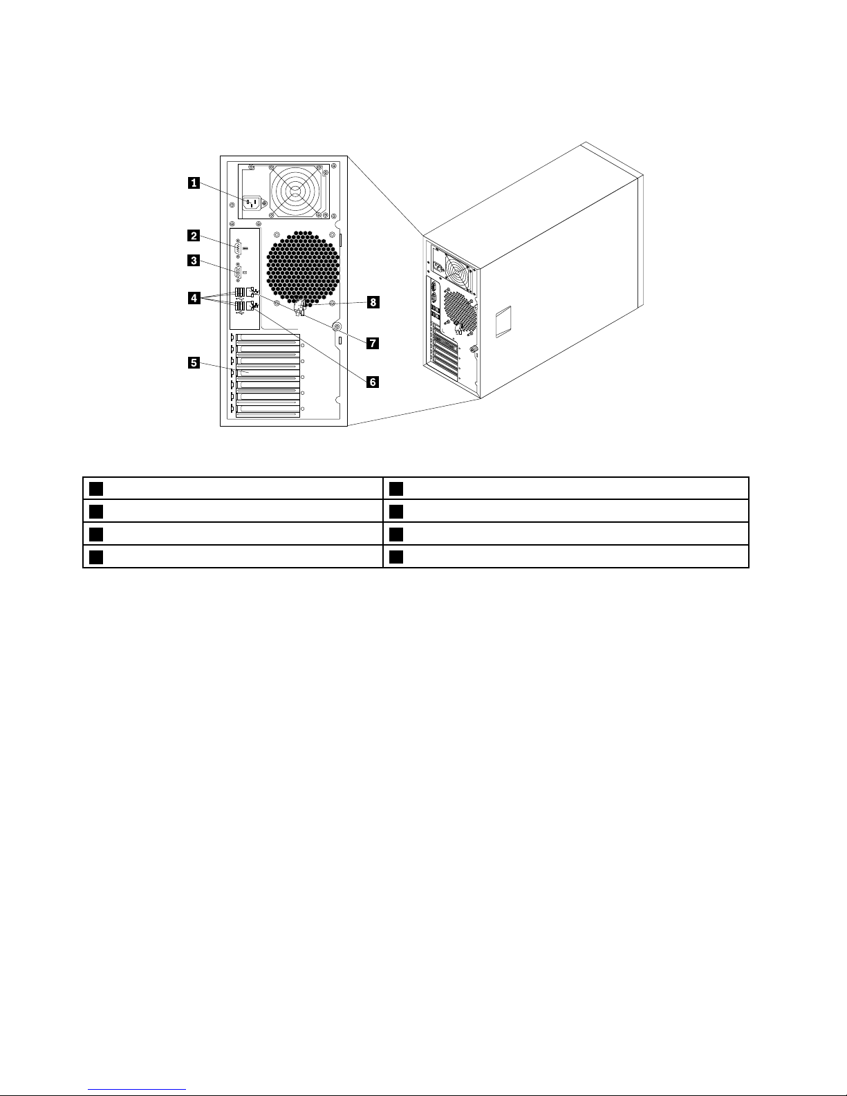
Thefollowingillustrationshowstherearviewoftheserverwithascrew-secured,non-hot-swappowersupply.
Figure6.Rearviewoftheserverwithanon-hot-swappowersupply
1Powercordconnector5Expansioncardarea
2Serialport6Ethernetconnector1(RJ-45)
3VGADB-15connector7Ethernetconnector2(RJ-45)(forsystemmanagement)
4FourUSBconnectors
8Frontdoorkey
20ThinkServerUserGuide
Page 33
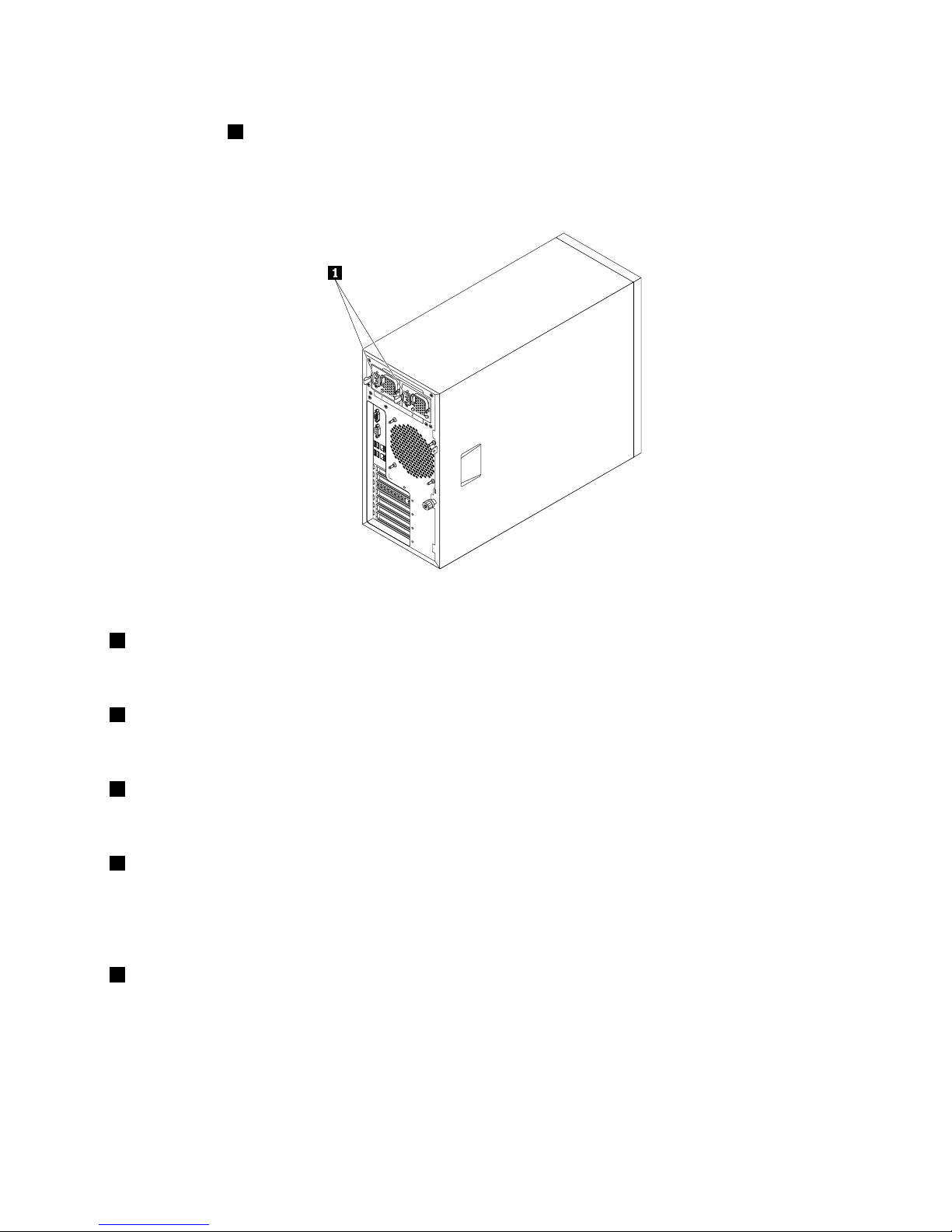
Forservermodelsthathavehot-swapredundantpowersupplymodule(s),theremightbeoneortwopower
cordconnectors1ontherearoftheserver.Foreachhot-swapredundantpowersupplymodule,there
mightbeoneortwostatusLEDsonthepowersupplymodulenearthepowercordconnector.Whenthe
greenLEDislit,itindicatesthatthehot-swapredundantpowersupplymoduleisworkingproperly.When
theredLEDislit,itindicatesthatthehot-swapredundantpowersupplymodulehasfailed.
Figure7.Rearviewoftheserverwithhot-swapredundantpowersupplymodules
1Powercordconnector(s)
Usedtoconnectthepowercord(s).
2Serialport
Usedtoattachadevicethatusesa9-pinserialport.
3VGADB-15connector
Usedtoattachavideodevice,suchasaVGAmonitororotherdevicesthatuseaVGADB-15connector.
4USBconnectors
UsedtoattachadevicethatrequiresaUSBconnector,suchasaUSBkeyboard,aUSBmouse,aUSB
scanner,oraUSBprinter.IfyouhavemorethansixUSBdevices,youcanpurchaseaUSBhub,which
youcanusetoconnectadditionalUSBdevices.
5Expansioncardarea
YouserverhasfourexpansionslotsonthesystemboardforyoutoinstallappropriatePCIcards.For
detailedinformation,see“Systemboardcomponents”onpage42
.
Chapter3.Productoverview21
Page 34
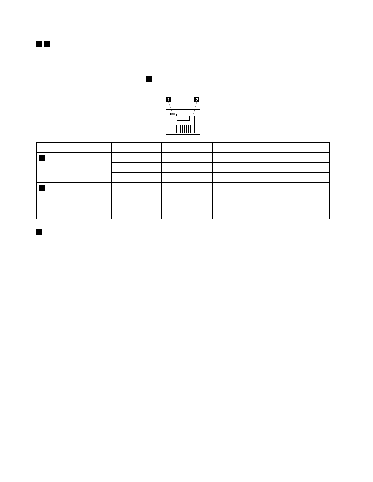
67Ethernetconnectors
UsedtoattachanEthernetcableforaLAN.EachEthernetconnectorhastwostatusLEDstohelpyou
identifytheEthernetconnectivity,activity,andconnectionspeed.
Note:TheEthernetconnector2(callout7)markedwith“MGMT”isforsystemmanagement.Ifyouwantto
useremotemanagementfunctions,youneedtoconnectanEthernetcabletotheEthernetconnector2.
EthernetstatusLED
ColorStatus
Description
GreenOn
TheserverisconnectedtoaLAN.
None
Off
TheserverisdisconnectedfromaLAN.
1Left
Green
BlinkingTheLANisconnectedandactive.
Amber
On
Theconnectionspeedis1000Mbps
(megabitspersecond).
GreenOn
Theconnectionspeedis100Mbps.
2Right
None
Off
Theconnectionspeedis10Mbps.
8Frontdoorkey
Usedtoopenorlockthefrontdoor.
Note:Carefullysavethefrontdoorkeytoavoidloss.
Serverlocks
Lockingtheservercoverhelpspreventunauthorizedaccesstotheinsideofyourserverandlockingthefront
doorhelpspreventunauthorizedaccesstotheinstalledharddiskdrives.
Note:Dependingonthemodel,yourservermightlookslightlydifferentfromtheillustrationsinthistopic.
22ThinkServerUserGuide
Page 35
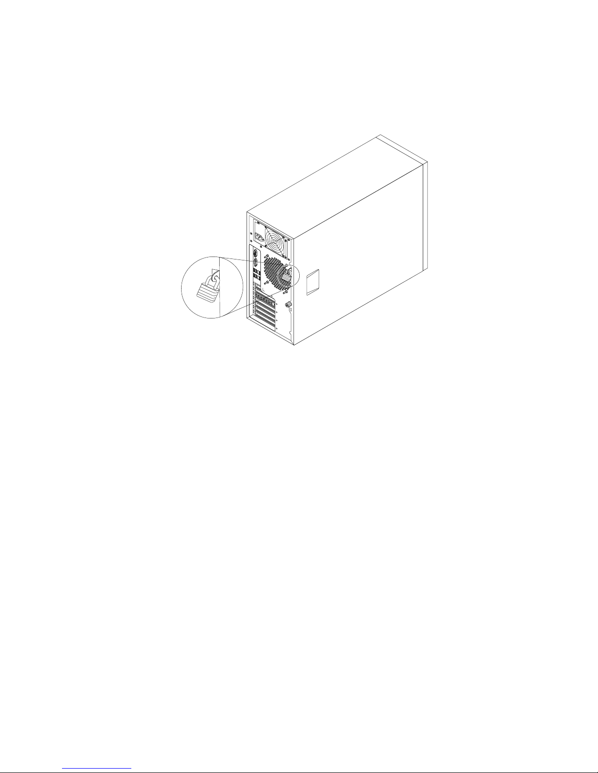
Padlock
Yourservercomeswithapadlockloopsothattheservercovercannotberemovedwhenapadlock
isinstalled.
Figure8.Padlock
Chapter3.Productoverview23
Page 36
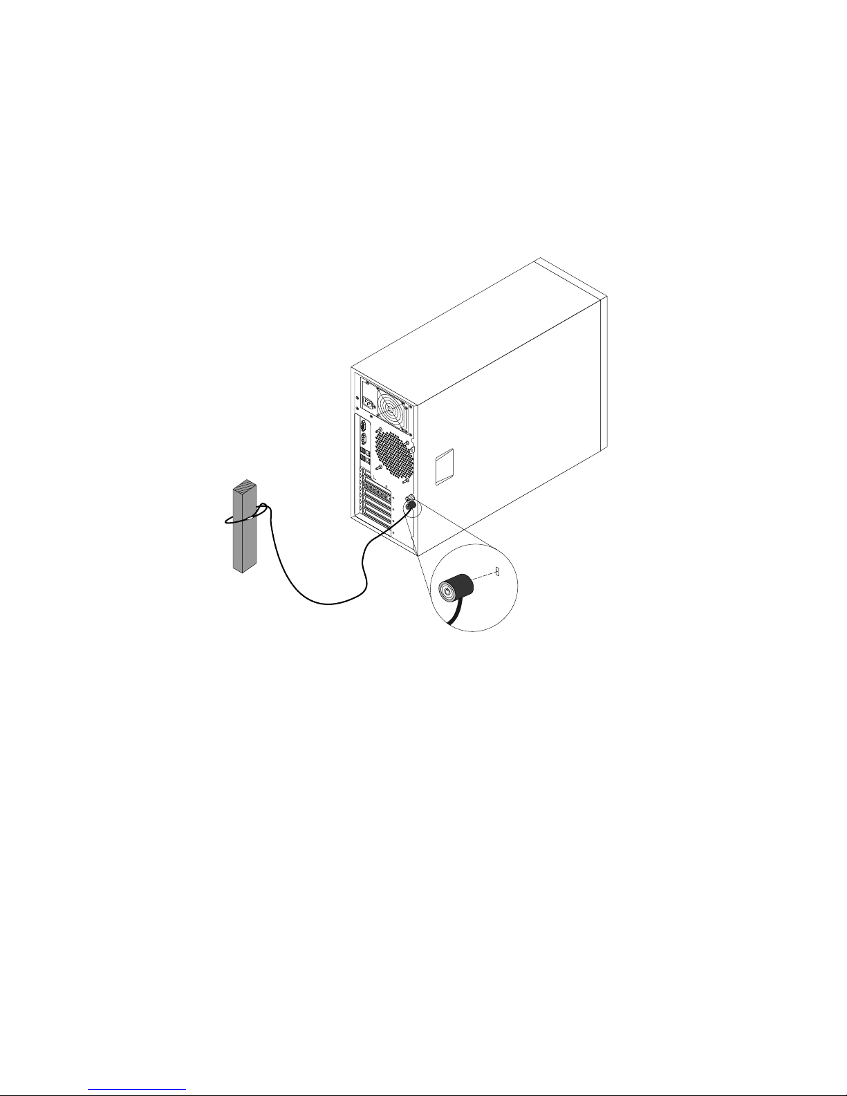
Integratedcablelock
Anintegratedcablelock,sometimesreferredtoastheKensingtonlock,canbeusedtosecureyourserverto
anon-permanentxture.Thecablelockattachestotheintegratedcablelockslotattherearofyourserver
andisoperatedwithakey.Thecablelockalsolockstheservercover.Thisisthesametypeoflockused
withmanynotebookcomputers.YoucanorderanintegratedcablelockdirectlyfromLenovobysearching
forKensingtonat:
http://www.lenovo.com/support
Figure9.Integratedcablelock
24ThinkServerUserGuide
Page 37
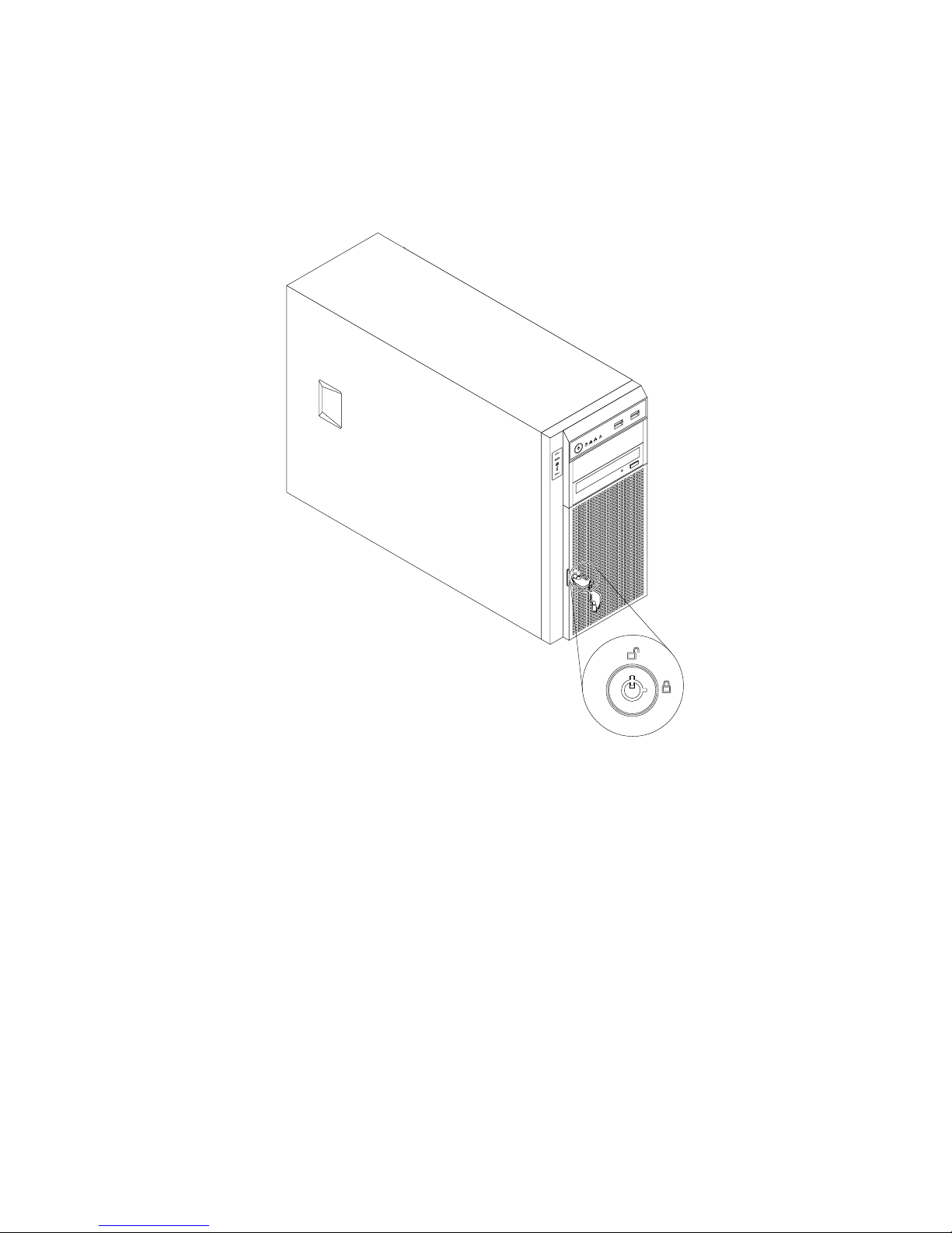
Frontdoorlock
Youcanremovethekeyattachedontheserveranduseittoopenorlockthefrontdooroftheserver.
Thefrontdoorhelpsprotecttheharddiskdrivecagestopreventunauthorizedaccesstotheinstalled
harddiskdrives.
Figure10.Frontdoorlock
Servercomponents
Thistopicprovidesinformationtohelpyoulocatethecomponentsofyourserver.
Toremovetheservercoverandgainaccesstotheinsideoftheserver,see“Removingtheservercover”
onpage85.
Thechassiscongurationvariesbymodel.Thefollowingillustrationsshowthefourmainchassis
congurationsbasedonthesupportedharddiskdrives.
Chapter3.Productoverview25
Page 38
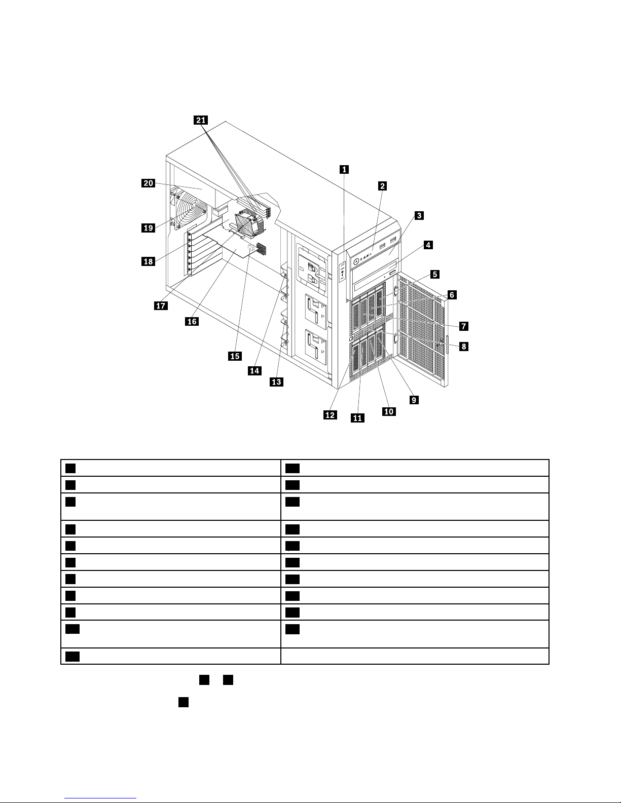
Thefollowingillustrationshowsthecomponentsoftheserverwithvetoeight3.5-inchhot-swaphard
diskdrives.
Figure11.Componentsoftheserverwithvetoeight3.5-inchhot-swapharddiskdrives
1DITmodule(availableinsomemodels)
12Harddiskdrivebay0
2Frontpanel
13Frontsystemfan1
3Opticaldrivebay2(withanopticaldriveinstalled
insomemodels)
14Frontsystemfan2
4Opticaldrivebay1(withanopticaldriveinstalled)15Systemboardbattery
5Harddiskdrivebay716Expansioncard
6Harddiskdrivebay6
17Heatsinkandfanassembly
7Harddiskdrivebay5
18Systemboard
8Harddiskdrivebay4
19Rearsystemfan
9Harddiskdrivebay320Powersupply
10Harddiskdrivebay2
21Fourmemoryslots(installedmemorymodulesvaryby
model)
11Harddiskdrivebay1
•Formoreinformationabout1to4,see“Frontviewoftheserver”onpage15.
Note:TheDITmodule1isonlyavailableinsomemodelsandtheDITpanelalsovariesbymodel.
See“DITmodule”onpage18
.
26ThinkServerUserGuide
Page 39

•Thereisa3.5-inchhot-swapharddiskdriveoradummyharddiskdrivetrayinstalledineachhard
diskdrivebay(5to12).
Note:Thenumberoftheinstalledharddiskdrivesvariesbymodel.Forthevacantdrivebay,thereisa
dummyharddiskdrivetraytocovertheplace.
•Forinformationaboutthesupportedexpansioncard,see“Systemboardcomponents”onpage42.
•Dependingonthemodel,yourservermightcomewithascrew-secured,non-hot-swappowersupply
orhot-swapredundantpowersupplymodule(s).
•Formoreinformationaboutthememorymodules,see“Memorymoduleinstallationrules”onpage90.
Chapter3.Productoverview27
Page 40
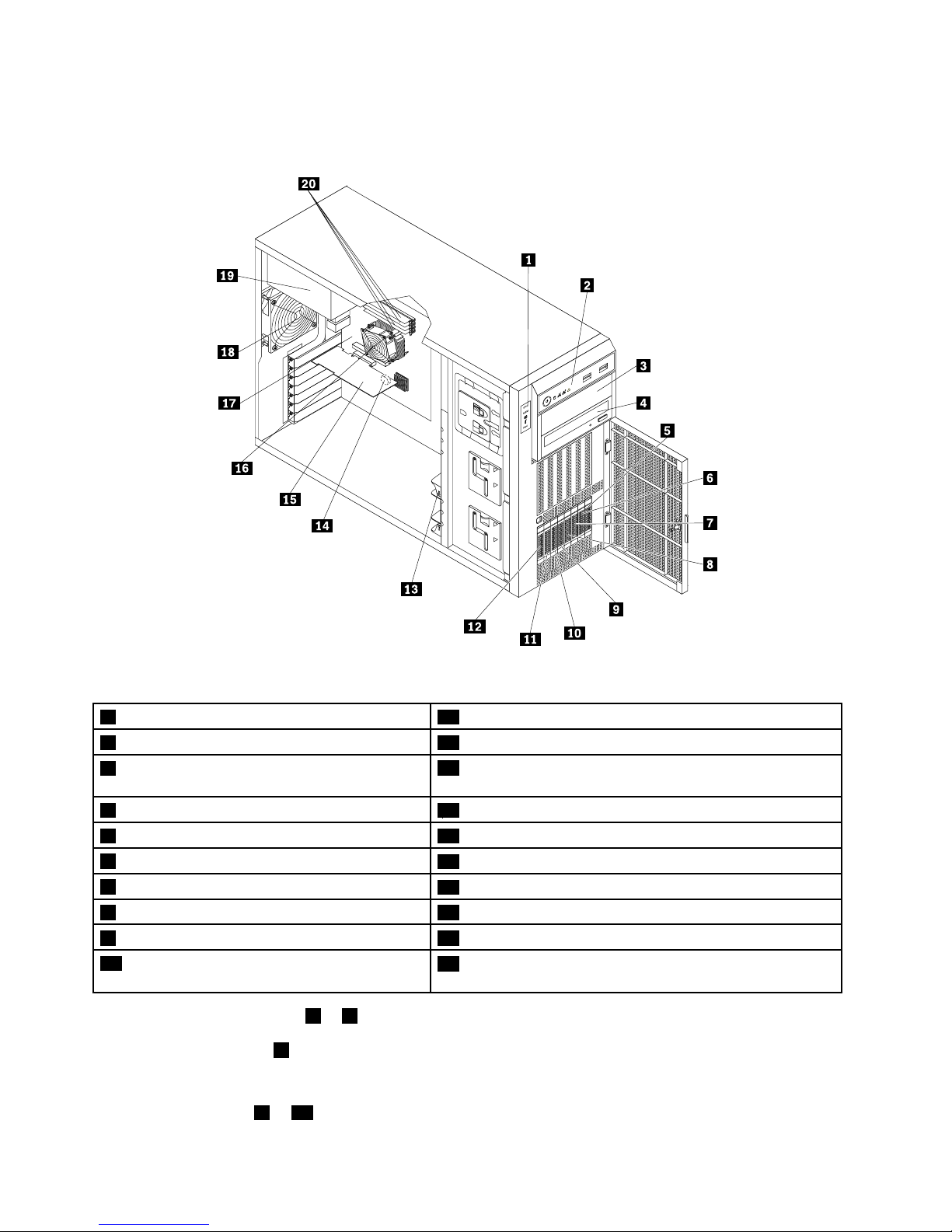
Thefollowingillustrationshowsthecomponentsoftheserverwithuptoeight2.5-inchhot-swapSAS
harddiskdrives.
Figure12.Componentsoftheserverwithuptoeight2.5-inchhot-swapSASharddiskdrives
1DITmodule(availableinsomemodels)
11Harddiskdrivebay1
2Frontpanel12Harddiskdrivebay0
3Opticaldrivebay2(withanopticaldriveinstalled
insomemodels)
13Frontsystemfan1
4Opticaldrivebay1(withanopticaldriveinstalled)14Systemboardbattery
5Harddiskdrivebay715Expansioncard
6Harddiskdrivebay6
16Heatsinkandfanassembly
7Harddiskdrivebay5
17Systemboard
8Harddiskdrivebay4
18Rearsystemfan
9Harddiskdrivebay319Powersupply
10Harddiskdrivebay2
20Fourmemoryslots(installedmemorymodulesvaryby
model)
•Formoreinformationabout1to4,see“Frontviewoftheserver”onpage15.
Note:TheDITmodule1isonlyavailableinsomemodelsandtheDITpanelalsovariesbymodel.
See“DITmodule”onpage18.
•Thereisa2.5-inchhot-swapSASharddiskdriveoradummyharddiskdrivetrayinstalledineach
harddiskdrivebay(5to12).
28ThinkServerUserGuide
Page 41
Note:Thenumberoftheinstalledharddiskdrivesvariesbymodel.Forthevacantdrivebay,thereisa
dummyharddiskdrivetraytocovertheplace.
•Forinformationaboutthesupportedexpansioncard,see“Systemboardcomponents”onpage42.
•Dependingonthemodel,yourservermightcomewithascrew-secured,non-hot-swappowersupply
orhot-swapredundantpowersupplymodule(s).
•Formoreinformationaboutthememorymodules,see“Memorymoduleinstallationrules”onpage90.
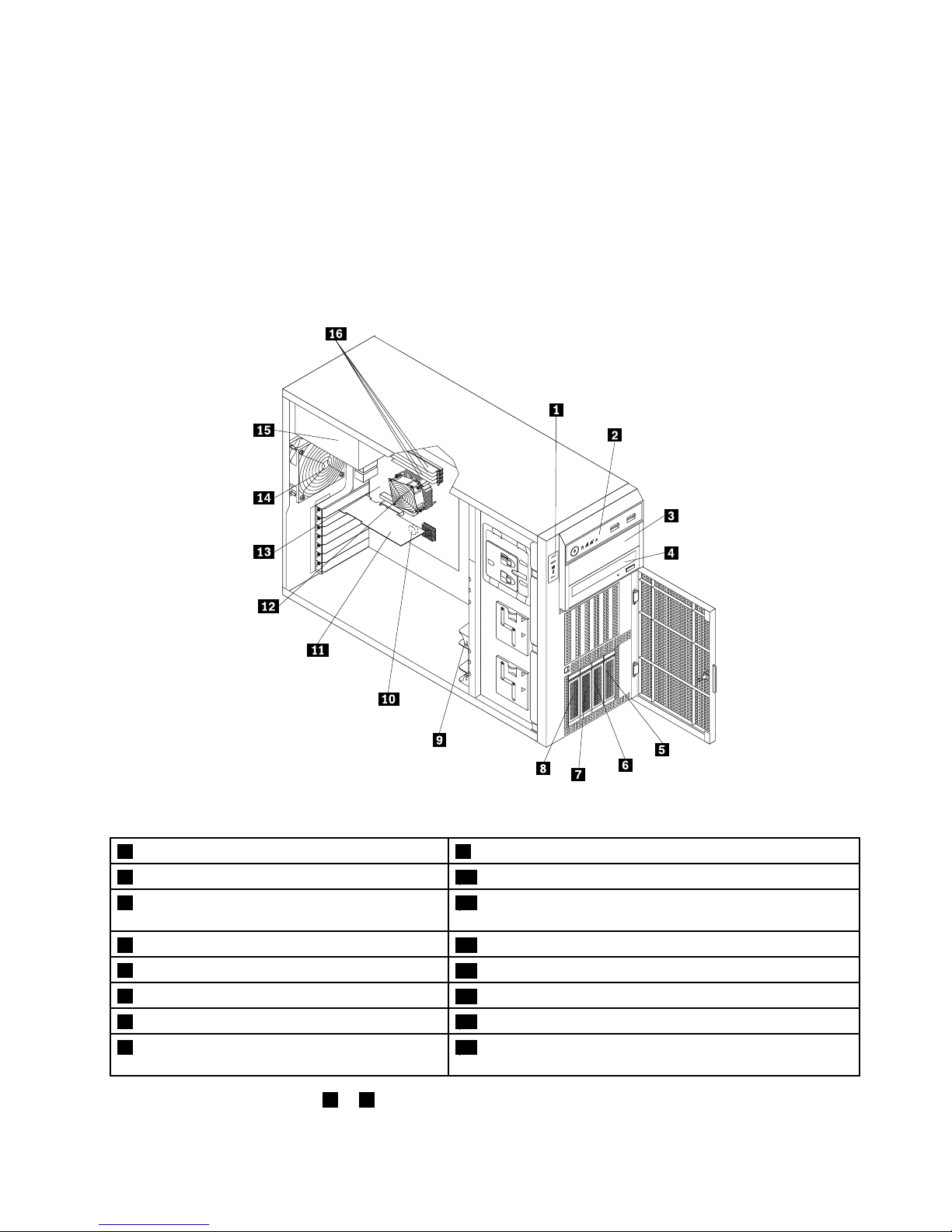
Thefollowingillustrationshowsthecomponentsoftheserverwithuptofour3.5-inchhot-swapharddisk
drives.
Figure13.Componentsoftheserverwithuptofour3.5-inchhot-swapharddiskdrives
1DITmodule(availableinsomemodels)
9Frontsystemfan1
2Frontpanel
10Systemboardbattery
3Opticaldrivebay2(withanopticaldriveinstalled
insomemodels)
11Expansioncard(variesbymodel)
4Opticaldrivebay1(withanopticaldriveinstalled)
12Heatsinkandfanassembly
5Harddiskdrivebay3
13Systemboard
6Harddiskdrivebay2
14Rearsystemfan
7Harddiskdrivebay115Powersupply
8Harddiskdrivebay0
16Fourmemoryslots(installedmemorymodulesvaryby
model)
•Formoreinformationabout1to4,see“Frontviewoftheserver”onpage15.
Chapter3.Productoverview29
Page 42

Note:TheDITmodule1isonlyavailableinsomemodelsandtheDITpanelalsovariesbymodel.
See“DITmodule”onpage18.
•Thereisa3.5-inchhot-swapharddiskdriveoradummyharddiskdrivetrayinstalledineachhard
diskdrivebay(5to8).
Note:Thenumberoftheinstalledharddiskdrivesvariesbymodel.Forthevacantdrivebay,thereisa
dummyharddiskdrivetraytocovertheplace.
•Forinformationaboutthesupportedexpansioncard,see“Systemboardcomponents”onpage42.
•Dependingonthemodel,yourservermightcomewithascrew-secured,non-hot-swappowersupply
orhot-swapredundantpowersupplymodule(s).
•Formoreinformationaboutthememorymodules,see“Memorymoduleinstallationrules”onpage90.
30ThinkServerUserGuide
Page 43
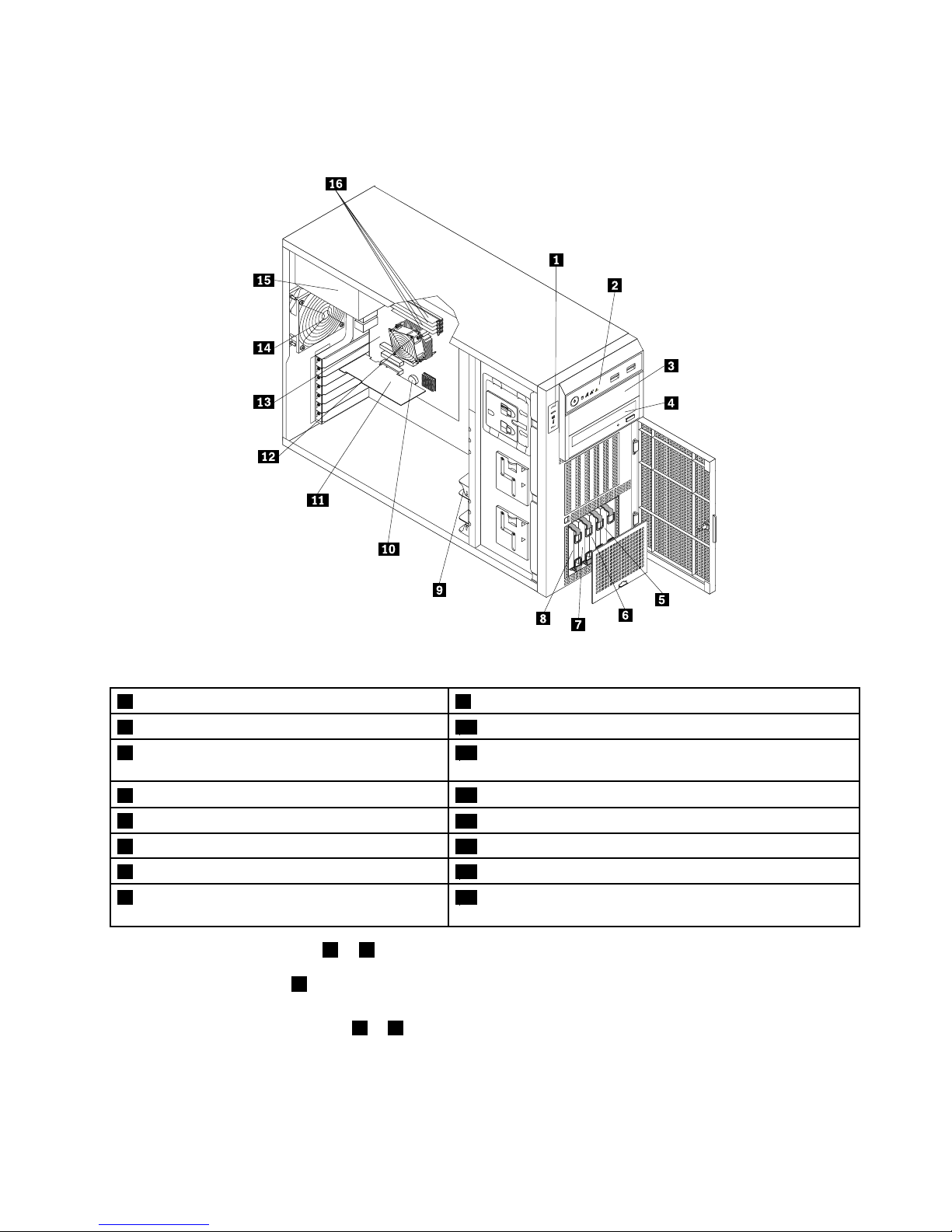
Thefollowingillustrationshowsthecomponentsoftheserverwithuptofour3.5-inchnon-hot-swaphard
diskdrives.
Figure14.Componentsoftheserverwithuptofour3.5-inchnon-hot-swapharddiskdrives
1DITmodule(availableinsomemodels)
9Frontsystemfan1
2Frontpanel
10Systemboardbattery
3Opticaldrivebay2(withanopticaldriveinstalled
insomemodels)
11Expansioncard(variesbymodel)
4Opticaldrivebay1(withanopticaldriveinstalled)
12Heatsinkandfanassembly
5Harddiskdrivebay3
13Systemboard
6Harddiskdrivebay2
14Rearsystemfan
7Harddiskdrivebay115Powersupply
8Harddiskdrivebay0
16Fourmemoryslots(installedmemorymodulesvaryby
model)
•Formoreinformationabout1to4,see“Frontviewoftheserver”onpage15.
Note:TheDITmodule1isonlyavailableinsomemodelsandtheDITpanelalsovariesbymodel.
See“DITmodule”onpage18.
•Eachoftheharddiskdrivebay(5to8)isusedforinstallinga3.5-inchnon-hot-swapharddiskdrives.
Note:Thenumberoftheinstalledharddiskdrivesvariesbymodel.
•Forinformationaboutthesupportedexpansioncard,see“Systemboardcomponents”onpage42.
Chapter3.Productoverview31
Page 44

•Dependingonthemodel,yourservermightcomewithascrew-secured,non-hot-swappowersupply
orhot-swapredundantpowersupplymodule(s).
•Formoreinformationaboutthememorymodules,see“Memorymoduleinstallationrules”onpage90.
Hot-swapharddiskdrivestatusLEDs
Thistopicappliesonlytoservermodelswithhot-swapharddiskdrives.
Note:Dependingonthemodel,yourservermightlookslightlydifferentfromtheillustrationsinthistopic.
Eachhot-swapharddiskdrivehastwostatusLEDsonthefront.Unlockandopenthefrontdoortogain
accesstotheharddiskdrivesandviewthestatusLEDs.
Figure15.3.5-inchhot-swapharddiskdrivestatusLEDs
32ThinkServerUserGuide
Page 45
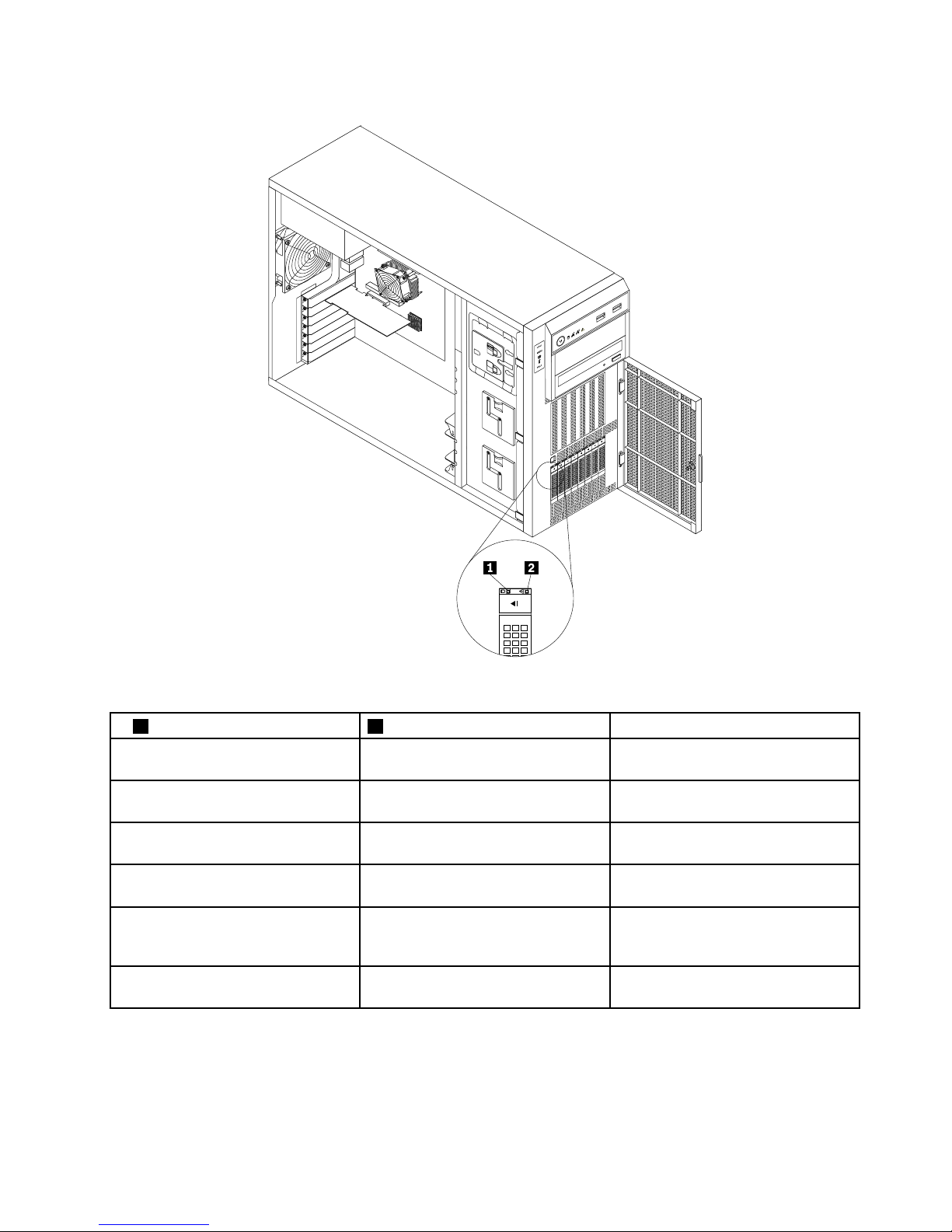
Figure16.2.5-inchhot-swapharddiskdrivestatusLEDs
1HarddiskdriveactivityLED2HarddiskdriveRAIDstatusLEDDescription
OffOff
Theharddiskdrivehasfailedoris
notpresent.
On,greenOff
Theharddiskdriveispresentbutnot
inuse.
Blinking,green
Off
Theharddiskdriveisactiveanddata
isbeingtransferred.
On,greenBlinkingrapidly(aboutfourashes
persecond),amber
TheRAIDcontrollerisidentifyingthe
harddiskdrive.
On,greenOn,amber
TheRAIDarrayhasfailedandcannot
recover.Youneedtorecreateanew
array.
Blinking,green
Blinkingslowly(aboutoneashper
second),amber
Theharddiskdriveisbeingrebuilt.
RAIDcard
ThistopicprovidesinformationtohelpyoulocatetheconnectorsonaRAIDcardifyouhaveoneinstalledin
thePCI-Eslot3onthesystemboard.See“Systemboardcomponents”onpage42
.
Chapter3.Productoverview33
Page 46
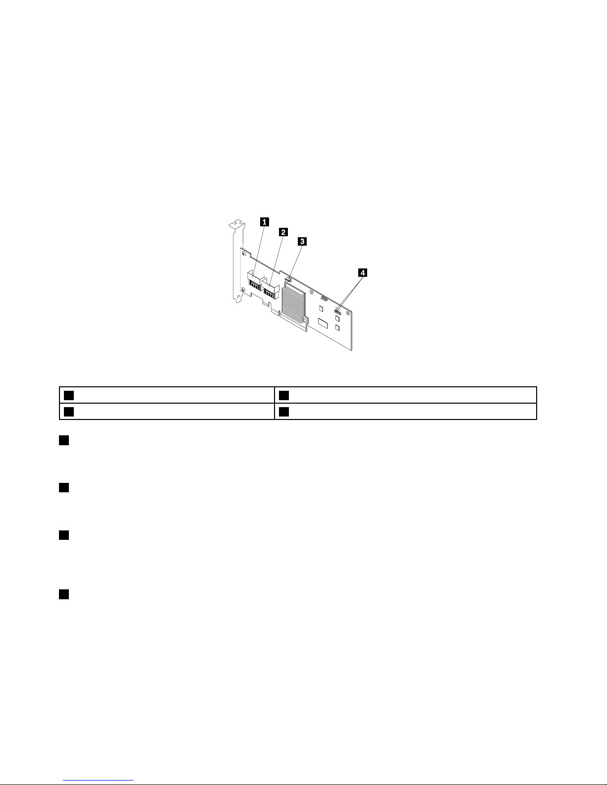
SomeservermodelscomewitharequiredRAIDcardtoprovideadvancedSATA/SAShardwareRAID
functionstotheserver.YoucanalsopurchasetheRAIDcardfromLenovoandinstallitintomodelsthat
supporttheRAIDcardtogetadvancedSATA/SAShardwareRAIDfunctions.See“Installingorremoving
theRAIDcard”onpage98
.
Note:ForservermodelswithmorethanfourharddiskdrivesormodelsthatuseSASharddiskdrives,there
mustbeaRAIDcardinstalled.
Optionname:ThinkServer9240-8iRAID0/1Adapter(hereinafterreferredtoastheRAIDcard)
ThefollowingillustrationshowstheconnectorsontheRAIDcard.
Figure17.ThinkServer9240-8iRAID0/1Adapter
1Port03RAID5keyconnector
2Port14Externalconnector
1Port0
Usedtoconnectamini-SASsignalcable.See“Connectingcables”onpage38
.
2Port1
Usedtoconnectamini-SASsignalcable.See“Connectingcables”onpage38.
3RAID5keyconnector
UsedtoconnectaThinkServer9240-8iRAID5UpgradeKey.See“InstallingorremovingtheThinkServer
9240-8iRAID5UpgradeKey”onpage100.
4Externalconnector
Usedtoconnecta2-pin200mm(7.87inches)RAIDcardtosystemboardharddiskdriveLEDcable.
See“Connectingcables”onpage38.
Hot-swapharddiskdrivebackplane
Yourserversupportsthefollowinghot-swapharddiskdriveandbackplanecongurations:
•Fivetoeight3.5-inchhot-swapSATAorSASharddiskdriveswithtwobackplanes
•Uptofour3.5-inchhot-swapSATAorSASharddiskdriveswithonebackplane
34ThinkServerUserGuide
Page 47

•Uptoeight2.5-inchhot-swapSASharddiskdriveswithonebackplane
Thefollowingillustrationshowsthelocationsofthehot-swapharddiskdrivebackplanes.Y ouneedtoopen
theservercoverandremovethefrontsystemfanstoaccessthebackplanes.See“Removingtheserver
cover”onpage85and“Replacingthefrontsystemfan”onpage149.
Notes:
1.Dependingonthemodel,yourservermightlookslightlydifferentfromtheillustrationinthistopic.
2.Thefollowingillustrationisbasedonvetoeight3.5-inchhot-swapSATAorSASharddiskdrives
withtwobackplanes
1.
Figure18.Hot-swapharddiskdrivebackplanelocations
Backplanefor3.5-inchhot-swapharddiskdrives
Thistopicprovidesinformationtohelpyoulocatetheconnectorsona3.5-inchhot-swapharddiskdrive
backplane.
Chapter3.Productoverview35
Page 48
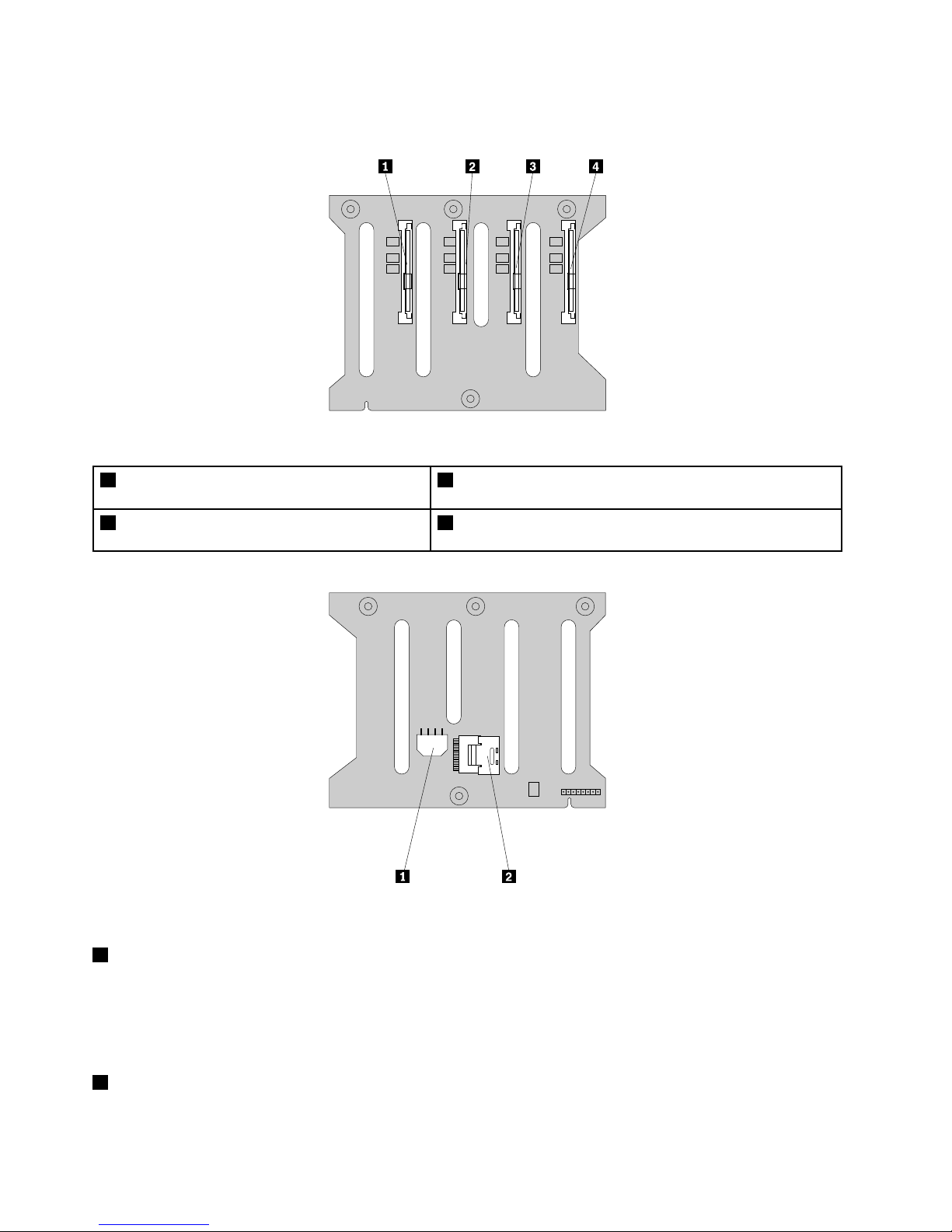
Thefollowingillustrationsshowtheconnectorsona3.5-inchhot-swapharddiskdrivebackplane.
Figure19.Frontviewofthe3.5-inchhot-swapharddiskdrivebackplane
1Slot0fora3.5-inchSATAorSAShot-swaphard
diskdrive
3Slot2fora3.5-inchSATAorSAShot-swapharddiskdrive
2Slot1fora3.5-inchSATAorSAShot-swaphard
diskdrive
4Slot3fora3.5-inchSATAorSAShot-swapharddiskdrive
Figure20.Rearviewofthe3.5-inchhot-swapharddiskdrivebackplane
18-pinpowerconnector
•For3.5-inchhot-swapharddiskdrivebackplaneonthelowerharddiskdrivecage,connecttheP5power
connectorofthepowersupplytothe8-pinpowerconnectoronthebackplane.
•For3.5-inchhot-swapharddiskdrivebackplaneontheupperharddiskdrivecage,connecttheP4power
connectorofthepowersupplytothe8-pinpowerconnectoronthebackplane.
2Mini-SASsignalcableconnector
Usedtoconnectthemini-SASconnectorononeendofthemini-SASsignalcable.
36ThinkServerUserGuide
Page 49
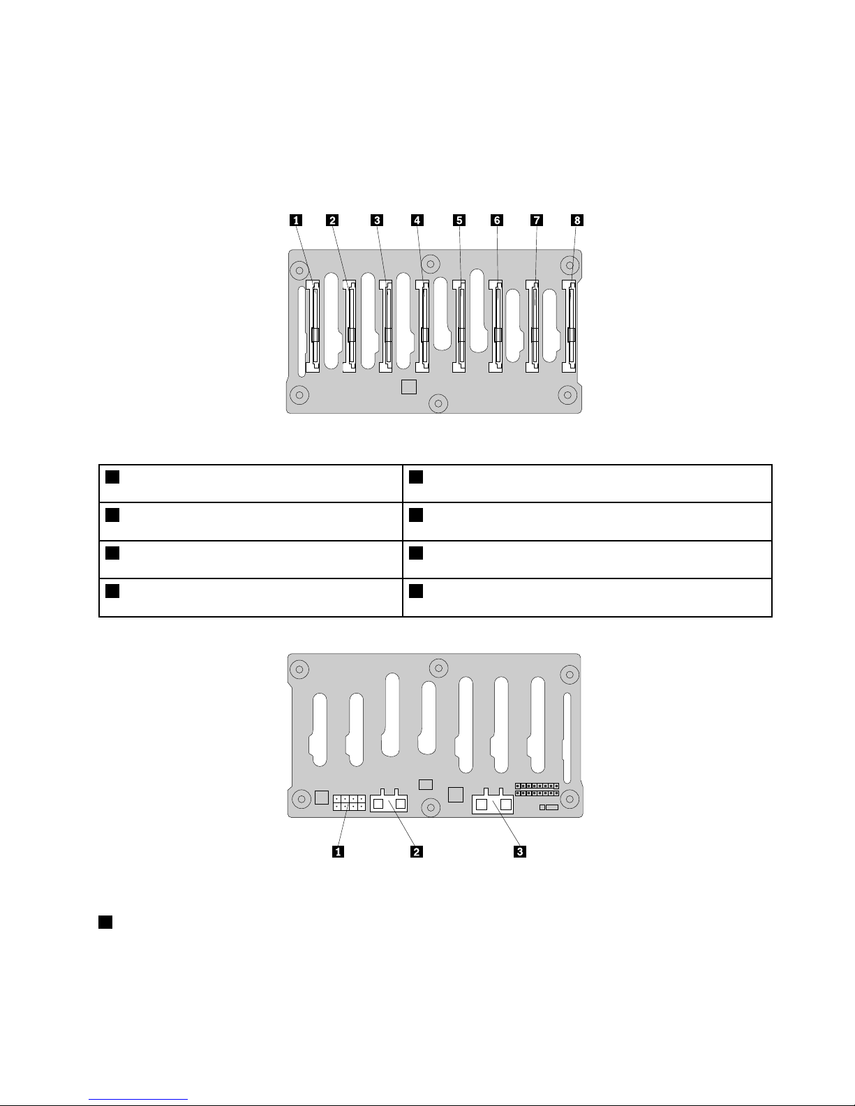
Backplanefor2.5-inchhot-swapharddiskdrives
Thistopicprovidesinformationtohelpyoulocatetheconnectorsonthe2.5-inchhot-swapharddisk
drivebackplane.
Thefollowingillustrationsshowtheconnectorsonthe2.5-inchhot-swapharddiskdrivebackplane.
Figure21.Frontviewofthe2.5-inchhot-swapharddiskdrivebackplane
1Slot0fora2.5-inchSAShot-swapharddisk
drive
5Slot4fora2.5-inchSAShot-swapharddiskdrive
2Slot1fora2.5-inchSAShot-swapharddisk
drive
6Slot5fora2.5-inchSAShot-swapharddiskdrive
3Slot2fora2.5-inchSAShot-swapharddisk
drive
7Slot6fora2.5-inchSAShot-swapharddiskdrive
4Slot3fora2.5-inchSAShot-swapharddisk
drive
8Slot7fora2.5-inchSAShot-swapharddiskdrive
Figure22.Rearviewofthe2.5-inchhot-swapharddiskdrivebackplane
18-pinpowerconnector
UsedtoconnecttheP5powerconnectorofthepowersupply.
Chapter3.Productoverview37
Page 50

2Mini-SASsignalcableconnector2
Usedtoconnectthemini-SASconnectorononeendofthemini-SASsignalcable.
3Mini-SASsignalcableconnector1
Usedtoconnectthemini-SASconnectorononeendofthemini-SASsignalcable.
Connectingcables
Thistopicprovidesinstructionsonhowtoconnectthemini-SASsignalcable(s)tothehot-swapharddisk
drivebackplane(s)andthesystemboardortherequiredRAIDcardifyouhaveoneinstalled.
Thistopicappliesonlytoservermodelsthathavehot-swapharddiskdrive(s)installedandthecable
connectionsaredifferentdependingonthefollowingcongurations:
•Servermodelswithvetoeight3.5-inchhot-swapharddiskdrivesandtwobackplanes
•Servermodelswithuptoeight2.5-inchSAShot-swapharddiskdrivesandonebackplane
•Servermodelswithuptofour3.5-inchhot-swapharddiskdrivesandonebackplane
Servermodelswithvetoeight3.5-inchhot-swapharddiskdrivesandtwobackplanes
ForservermodelswithvetoeightSASorSATAII3.5-inchhot-swapharddiskdrivesandtwobackplanes,a
requiredRAIDcardmustbeinstalledintheserver.
ThefollowingcablesthatcomewiththeRAIDcardarerequired:
Note:TheoptionpackagefortheRAIDcardisdesignedfordifferenttypesofserversandmightcontain
additionalcablesthatarenotrequiredtobeinstalledintoyourserver.
•Two700mm(27.56inches)mini-SAStomini-SASsignalcables
•One2-pin200mm(7.87inches)RAIDcardtosystemboardharddiskdriveLEDcable
38ThinkServerUserGuide
Page 51
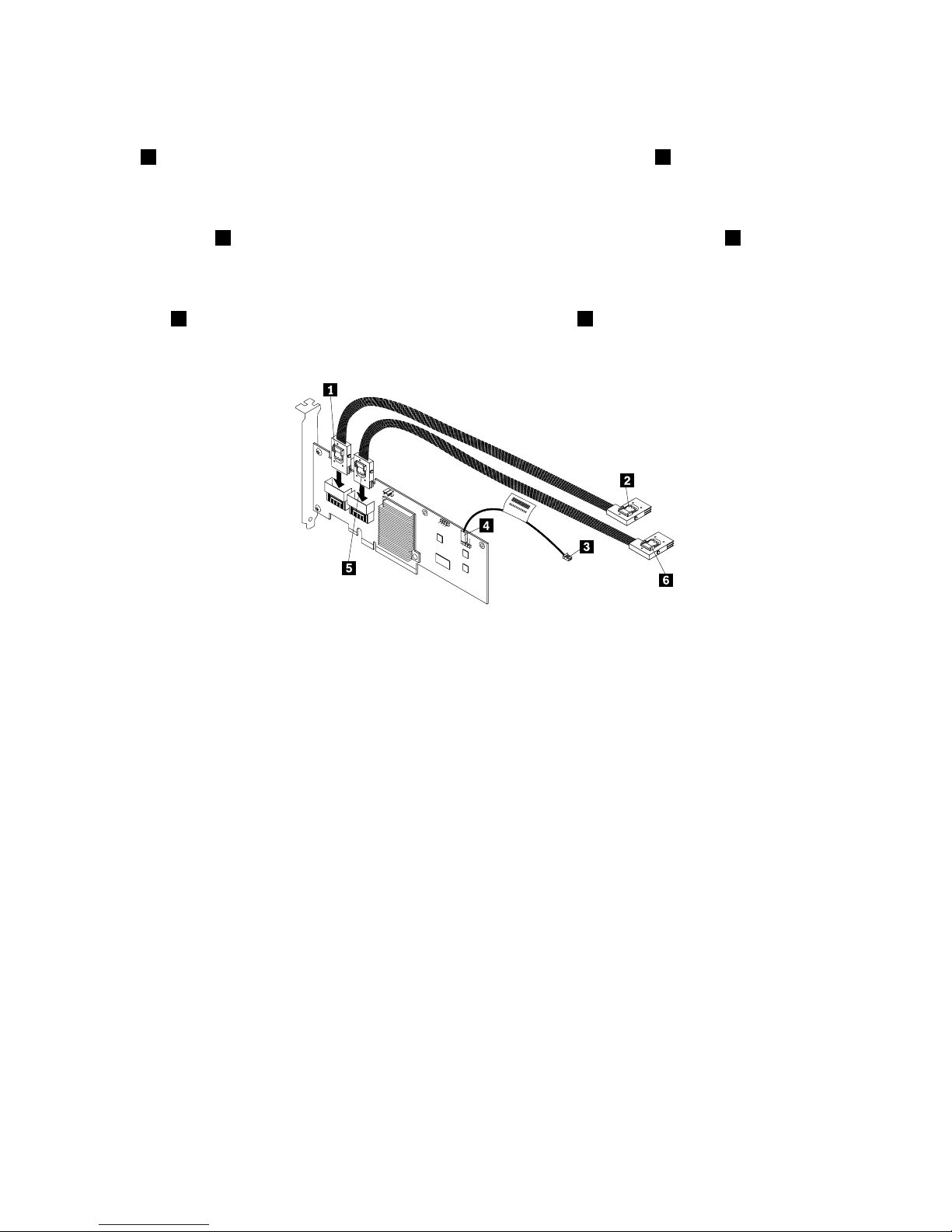
Usethefollowinginstructionstoconnectthecables:
1.Useone700mm(27.56inches)mini-SAStomini-SASsignalcable.Connectthemini-SASconnector
1totheport0ontheRAIDcard.Then,connectthemini-SASconnector2tothemini-SASsignal
cableconnectoronthe3.5-inchhot-swapharddiskdrivebackplaneinstalledonthelowerharddisk
drivecage.
2.Usetheother700mm(27.56inches)mini-SAStomini-SASsignalcable.Connectthemini-SAS
connector
5totheport1ontheRAIDcard.Then,connectthemini-SASconnector6tothemini-SAS
signalcableconnectoronthe3.5-inchhot-swapharddiskdrivebackplaneinstalledontheupper
harddiskdrivecage.
3.Usethe2-pin200mm(7.87inches)RAIDcardtosystemboardharddiskdriveLEDcable.Connectthe
end4totheexternalconnectorontheRAIDcardandtheend3totheharddiskdriveLEDconnector
onthesystemboard.
Figure23.ConnectingcablesforservermodelswithtwobackplanesandaRAIDcard
ForconnectorlocationinformationabouttheRAIDcard,hot-swapharddiskdrivebackplane,andthe
systemboard,refertotherelatedtopicsin“Locations”onpage13.
Forinformationaboutconnectingtheappropriatepowerconnectorofthepowersupplytothebackplane,
see“Hot-swapharddiskdrivebackplane”onpage34
.
Servermodelswithuptoeight2.5-inchSAShot-swapharddiskdrivesandonebackplane
Forservermodelswithuptoeight2.5-inchSAShot-swapharddiskdrivesandonebackplane,arequired
RAIDcardmustbeinstalledintheserver.
ThefollowingcablesthatcomewiththeRAIDcardarerequired:
Note:TheoptionpackagefortheRAIDcardisdesignedfordifferenttypesofserversandmightcontain
additionalcablesthatarenotrequiredtobeinstalledintoyourserver.
•Oneortwo700mm(27.56inches)mini-SAStomini-SASsignalcablesdependingonthenumberof
theharddiskdrivesinstalled
•One2-pin200mm(7.87inches)RAIDcardtosystemboardharddiskdriveLEDcable
Chapter3.Productoverview39
Page 52
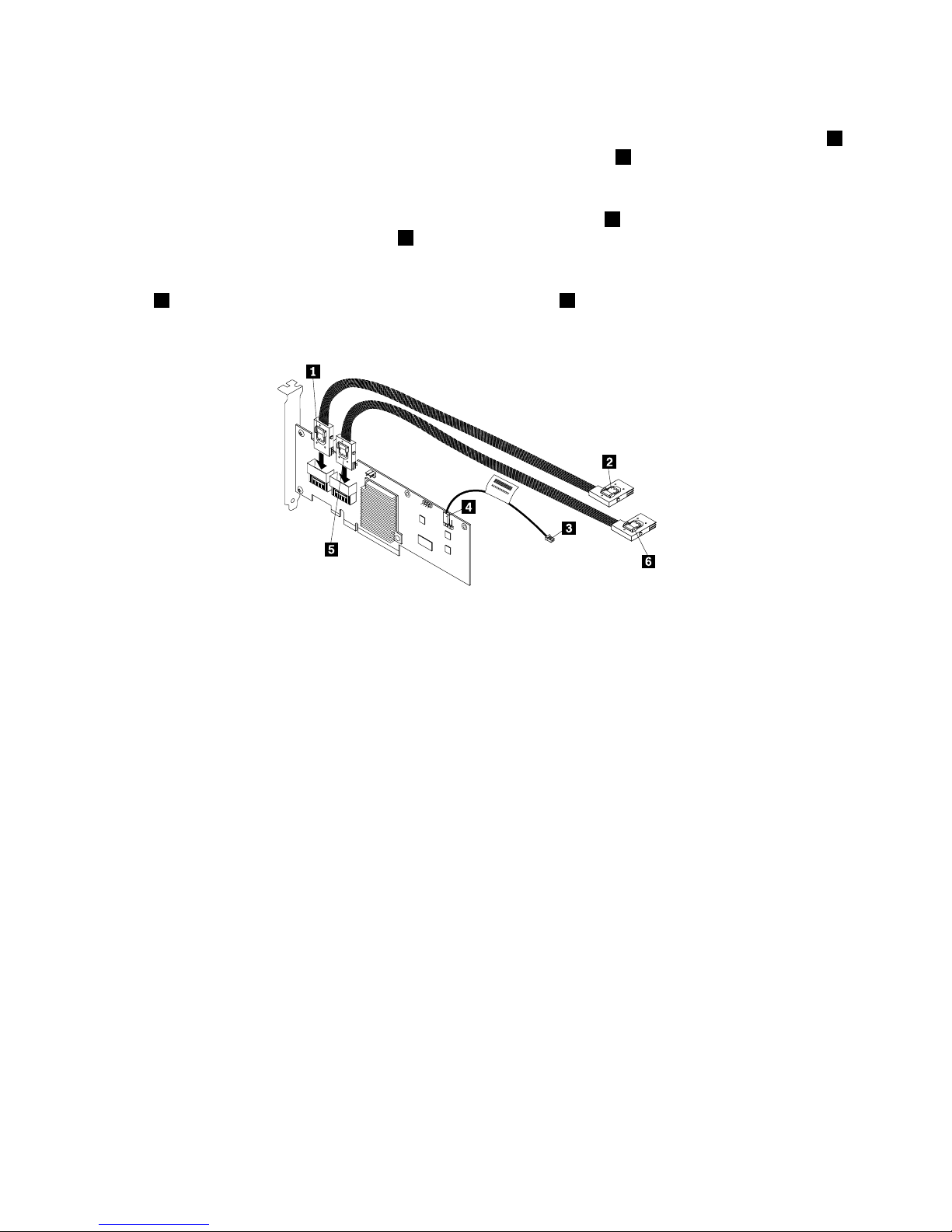
Usethefollowinginstructionstoconnectthecables:
1.Useone700mm(27.56inches)mini-SAStomini-SASsignalcable.Connectthemini-SASconnector1
totheport0ontheRAIDcard.Then,connectthemini-SASconnector2tothemini-SASsignalcable
connector1onthe2.5-inchhot-swapharddiskdrivebackplane.
2.Ifyouhavemorethanfour2.5-inchharddiskdrivesinstalled,usetheother700mm(27.56inches)
mini-SAStomini-SASsignalcable.Connectthemini-SASconnector5totheport1ontheRAIDcard.
Then,connectthemini-SASconnector
6tothemini-SASsignalcableconnector2onthe2.5-inch
hot-swapharddiskdrivebackplane.
3.Usethe2-pin200mm(7.87inches)RAIDcardtosystemboardharddiskdriveLEDcable.Connectthe
end4totheexternalconnectorontheRAIDcardandtheend3totheharddiskdriveLEDconnector
onthesystemboard.
Figure24.Connectingcablesforservermodelswithone2.5-inchhot-swapharddiskdrivebackplaneandaRAIDcard
ForconnectorlocationinformationabouttheRAIDcard,hot-swapharddiskdrivebackplane,andthe
systemboard,refertotherelatedtopicsin“Locations”onpage13.
Forinformationaboutconnectingtheappropriatepowerconnectorofthepowersupplytothebackplane,
see“Hot-swapharddiskdrivebackplane”onpage34.
Servermodelswithuptofour3.5-inchhot-swapharddiskdrivesandonebackplane
Forservermodelswithuptofour3.5-inchSATAhot-swapharddiskdrivesandonebackplane,youcaneither
connecttheSATAharddiskdrive(s)totheSATAconnectorsonthesystemboardorarequiredRAIDcardif
youhaveoneinstalledintheserver.Forservermodelswithuptofour3.5-inchSAShot-swapharddisk
drivesandonebackplane,connecttheSASharddiskdrive(s)totherequiredRAIDcardinstalledintheserver.
Note:SATAIIistheonlytypeofSATAsupportedbytheRAIDcard.
Usethefollowinginstructionstoconnectthecables:
40ThinkServerUserGuide
Page 53
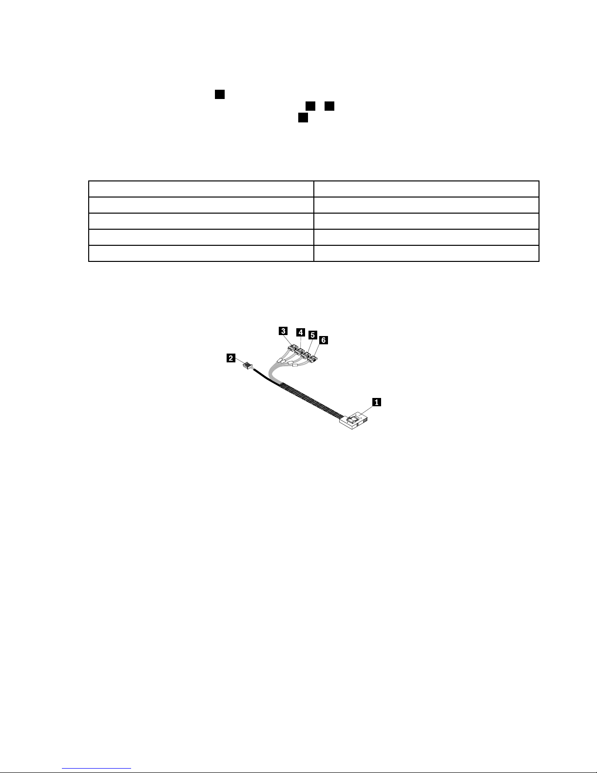
IfyouareconnectingtheSATAharddiskdrivestothesystemboard,usethe450mm(17.72inches)
mini-SASsignalcablewithfourSATAportsandoneSerialGeneralPurposeInput/Output(SGPIO)port.
Connectthemini-SASconnector1tothemini-SASsignalcableconnectoronthe3.5-inchhot-swaphard
diskdrivebackplaneandconnectthefourSATAports
3–6totheSATAconnector0toSATAconnector3
onthesystemboard.Then,connecttheSGPIOport2totheSATASGPIOconnectoronthesystemboard.
Notes:
1.ThenumberonthelabelforeachofthefourSATAsignalcablesindicatesthesequencewhenyouare
connectingthecablestothecorrespondingSATAconnectors(0-3)onthesystemboard.
SATAsignalcablelabelSystemboardSATAconnector
P0
SATAconnector0
P1
SATAconnector1
P2
SATAconnector2
P3
SATAconnector3
2.IfyouconnecttheSATAharddiskdrivestothesystemboard,youcancongureRAIDusingthe
congurationutilityfortheonboardSATAsoftwareRAID.See“ConguringtheonboardSATAsoftware
RAID”onpage75.
Figure25.Mini-SASsignalcablewithfourSAT AportsandoneSGPIOport
TheRAIDcardprovidesadvancedSATA/SASRAIDcongurations.IfyouareusingSAShot-swapharddisk
drives,youmusthavetheRAIDcardforconnectingtheSASharddiskdrives.Toconnecttheharddisk
drivestotheinstalledRAIDcard,thefollowingcablesthatcomewiththeRAIDcardarerequired:
Note:TheoptionpackagefortheRAIDcardisdesignedfordifferenttypesofserversandmightcontain
additionalcablesthatarenotrequiredtobeinstalledintoyourserver.
•One700mm(27.56inches)mini-SAStomini-SASsignalcable
•One2-pin200mm(7.87inches)RAIDcardtosystemboardharddiskdriveLEDcable
Chapter3.Productoverview41
Page 54
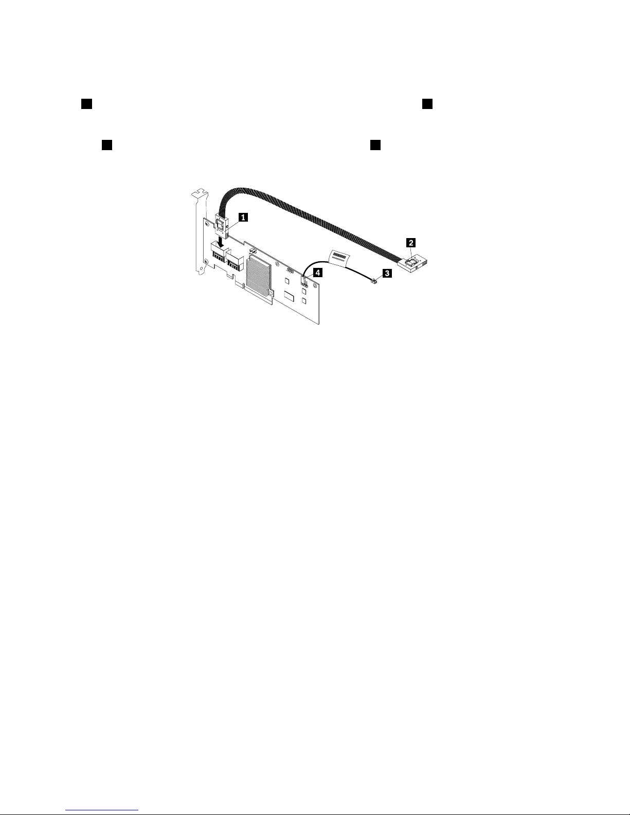
Toconnectthecables,dothefollowing:
1.Usethe700mm(27.56inches)mini-SAStomini-SASsignalcable.Connectthemini-SASconnector
1totheport0ontheRAIDcard.Then,connectthemini-SASconnector2tothemini-SASsignal
cableconnectoronthe3.5-inchhot-swapharddiskdrivebackplane.
2.Usethe2-pin200mm(7.87inches)RAIDcardtosystemboardharddiskdriveLEDcable.Connectthe
end4totheexternalconnectorontheRAIDcardandtheend3totheharddiskdriveLEDconnector
onthesystemboard.
Figure26.Connectingcablesforservermodelswithone3.5-inchhot-swapharddiskdrivebackplaneandaRAIDcard
ForconnectorlocationinformationabouttheRAIDcard,hot-swapharddiskdrivebackplane,andthe
systemboard,refertotherelatedtopicsin“Locations”onpage13.
Forinformationaboutconnectingtheappropriatepowerconnectorofthepowersupplytothebackplane,
see“Hot-swapharddiskdrivebackplane”onpage34.
Systemboardcomponents
Yourserversystemboardisasix-layermicro-ATXboardbasedontheIntelBromolowplatform.The
followingillustrationshowsthecomponentlocationsonthesystemboard.
42ThinkServerUserGuide
Page 55
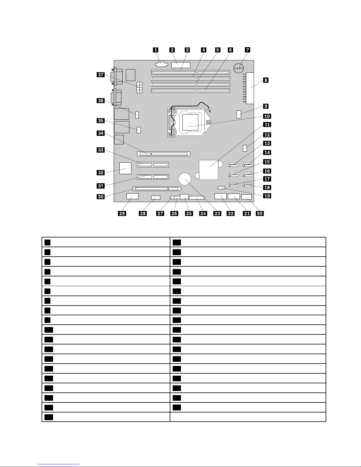
Figure27.Systemboardcomponents
1PowerManagementBus(PMBus)connector20InternalUSB2.0TypeAconnector
2TPMconnector
21Internaldual-portUSB2.0connector2
3Memoryslot4(DIMMB2)22Internaldual-portUSB2.0connector1
4Memoryslot3(DIMMB1)23Systemboardbattery
5Memoryslot2(DIMMA2)
24Frontpanelconnector
6Memoryslot1(DIMMA1)25Systemboardjumperblocks
7iButtonsocket
26SATASGPIOconnector
8Mainpowerconnector27HarddiskdriveLEDconnector
95-pinsystemfan2connector
28DITmoduleconnector
10Microprocessor29Internalserialconnector
11IntelC202chip30PCIcardslot(PCIslot1)
124-pinsystemfan1connector
31PCIExpressx4cardslot(PCI-Eslot2)
13SATAconnector132BMCchip
14SATAconnector033PCIExpressx8cardslot(PCI-Eslot3)
15SATAconnector334PCIExpressx8cardslot(PCI-Eslot4)
16SATAconnector2
35Microprocessorfanconnector
17SATAconnector536Systemfan3connector
18SATAconnector4
37Microprocessorpowerconnector
19iKVMkeyconnector
Chapter3.Productoverview43
Page 56
1PMBusconnector
TheBMCcanreadthepowersupplystatusregisteredthroughPMBus.Youdonotneedtoconnect
anydevicetothePMBusconnector.Thisconnectoriskeptforpowermanagementinmodelswith
redundantpowersupplymodules.ThefunctionofthePMBusconnectorisnotavailableformodelswitha
screw-securednon-hot-swappowersupply.
2TPMconnector
UsedtoconnectaTPMmodule,whichisasecuritychip,toprotectyourserverandstrengthenserver
security.See“InstallingorremovingtheTPMmodule”onpage109.
3–6Memoryslots
Yourserversystemboardprovidesfourmemoryslotstosupportuptofourmemorymodules.Formore
information,see“Memorymoduleinstallationrules”onpage90
.
7iButtonsocket
YourserversupportsonboardSATAsoftwareRAIDlevels0,1,and10.However,youcanactivateonboard
SATAsoftwareRAID5byinstallingaThinkServerSATASoftwareRAID5activationkeyintheiButtonsocket.
Formoreinformation,see“InstallingorremovingtheThinkServerSATASoftwareRAID5Key”onpage102.
8Mainpowerconnector
Usedtoconnectthe24-pinP1powerconnectorofthepowersupplytoprovidemainpowertoyourserver.
95-pinsystemfan2connector
Usedtoconnectthecableoftheupperfrontsystemfan(frontsystemfan2)ifyourservermodelhas
twofrontsystemfans.
10Microprocessor
Amicroprocessorincorporatesmostorallofthefunctionsofacomputer'scentralprocessingunit(CPU)on
asingleintegratedcircuit.Themicroprocessorforyourserverissecuredinthemicroprocessorsocketon
thesystemboardandaheatsinkandfanassemblyisinstalledabovethemicroprocessortoprovidecooling.
Formoreinformationaboutyourmicroprocessortype,see“Features”onpage7
.
11IntelC202chip
TheIntelC202chiponthesystemboardservesasaplatformcontrollerhub(PCH),whichprovidesthedata
bufferingandinterfacearbitrationrequiredtoensurethatsysteminterfacesoperateefcientlyandprovides
thebandwidthnecessarytoenablethesystemtoobtainpeakperformance.Thechipsupportsandprovides
manyfeatures,includingtheonboardSATAsoftwareRAID.
124-pinsystemfan1connector
Usedtoconnectthecableofthelowerfrontsystemfan(frontsystemfan1).
13–18SATAconnectors
UsedtoconnectSATAsignalcablesfortheSATAharddiskdrivesorSATAopticaldrives.
44ThinkServerUserGuide
Page 57
19iKVMkeyconnector
UsedtoconnectaniKVMkeyoption,whichisakindofremotemanagementmodule,toenabletheiKVM
functiononyourserver.See“InstallingorremovingtheThinkServeriKVMRemoteManagementModule”on
page105.
20InternalUSB2.0TypeAconnector
UsedtoconnectadevicethatusesaUSB2.0TypeAconnector.
21Internaldual-portUSB2.0connector2
UsedtoconnecttheUSBcableoftheRDXUSBdrivebundle(serveroption).
22Internaldual-portUSB2.0connector1
UsedtoconnectthefrontpanelUSBcable.
23Systemboardbattery
Yourserverhasaspecialtypeofmemorythatmaintainsthedate,time,andcongurationinformationfor
built-infeatures.Thesystemboardbatterykeepstheinformationactivewhenyouturnofftheserver.
24Frontpanelconnector
Usedtoconnectthefrontpanelcable.
25Systemboardjumperblocks
Usedtocongurethesystemboardandyourserver.See“Systemboardjumpers”onpage46.
26SATASGPIOconnector
UsedtoconnecttheSGPIOportofthemini-SASsignalcablewithfourSATAportsandoneSGPIOportto
enabletheRAIDstatusLEDsforhot-swapharddiskdrives.
27HarddiskdriveLEDconnector
Usedtoconnecta2-pin200mm(7.87inches)RAIDcardtosystemboardharddiskdriveLEDcable.
See“Connectingcables”onpage38.
28DITmoduleconnector
UsedtoconnectthecableoftheDITmoduleifyourserverhasoneinstalled.
29Internalserialconnector
Usedtoprovideanoptionalserialconnectorsolutionwitharequiredcable.
30PCIcardslot(PCIslot1)
Usedtoinstallastandard32-bit33MHzPCIcardwith167mm(6.57inches)inlength.
Chapter3.Productoverview45
Page 58
31PCIExpressx4cardslot(PCI-Eslot2)
ThisisaPCIExpressx4laneinphysicalPCI2.0x8slotthatsupportsaPCIExpressx4cardwith167mm
(6.57inches)inlength,suchasanEthernetcard.
32BMCchip
WiththeintegratedBMCchip,nomatterwhatconditiontheserveroperatingsystemisinandnomatterif
theserverisonoroff,aslongastheserverisconnectedtonetworkandanacpowersource,theinteraction
withtheBMCcontrolledserverscanbeachievedthroughsystemnetwork.Theusercanobtaintheserver
hardwarehealthinformationandSEL,andisabletoconducttheoperationsincludingturningonorofthe
server,restartingtheserver,lockingthepowerswitchonthefrontpanelandsoon.Thispartoftheserver
managementisindependentoftheoperatingsystemandiscalledout-of-bandmanagement.
33PCIExpressx8cardslot(PCI-Eslot3)
ThisisaPCIExpressx8laneinphysicalPCI2.0x8slotthatsupportsaPCIExpressx8cardwith167mm
(6.57inches)inlength,suchasanEthernetcardoraRAIDcard.
34PCIExpressx8cardslot(PCI-Eslot4)
ThisisaPCIExpressx8laneinphysicalPCI2.0x16slotthatsupportsaPCIExpressx8cardwith312mm
(12.28inches)inlength,suchasagraphicscard.
35Microprocessorfanconnector
Usedtoconnecttheheatsinkandfanassemblycable.
36Systemfan3connector
Usedtoconnecttherearsystemfancable.
37Microprocessorpowerconnector
Usedtoconnectthe8-pinP2powerconnectorofthepowersupplytoprovidepowertoyourmicroprocessor.
Systemboardjumpers
Thistopicprovidesinformationaboutthejumpersonthesystemboard.
Ajumperisashortlengthofconductorusedtosetuporadjustprintedcircuitboards,suchasthesystem
boardofacomputer.Ajumperisusuallyencasedinanon-conductiveblockofplasticforconvenientuse
andavoidinganypossibledamagetoalivecircuit.Jumperpinsarrangedingroupsonthesystemboardare
calledjumperblocks.Whentwoormorejumperpinsarecappedwithajumper,anelectricalconnectionis
madebetweenthemandtheequipmentisthusinstructedtoactivatecertainsettingsaccordingly.
46ThinkServerUserGuide
Page 59
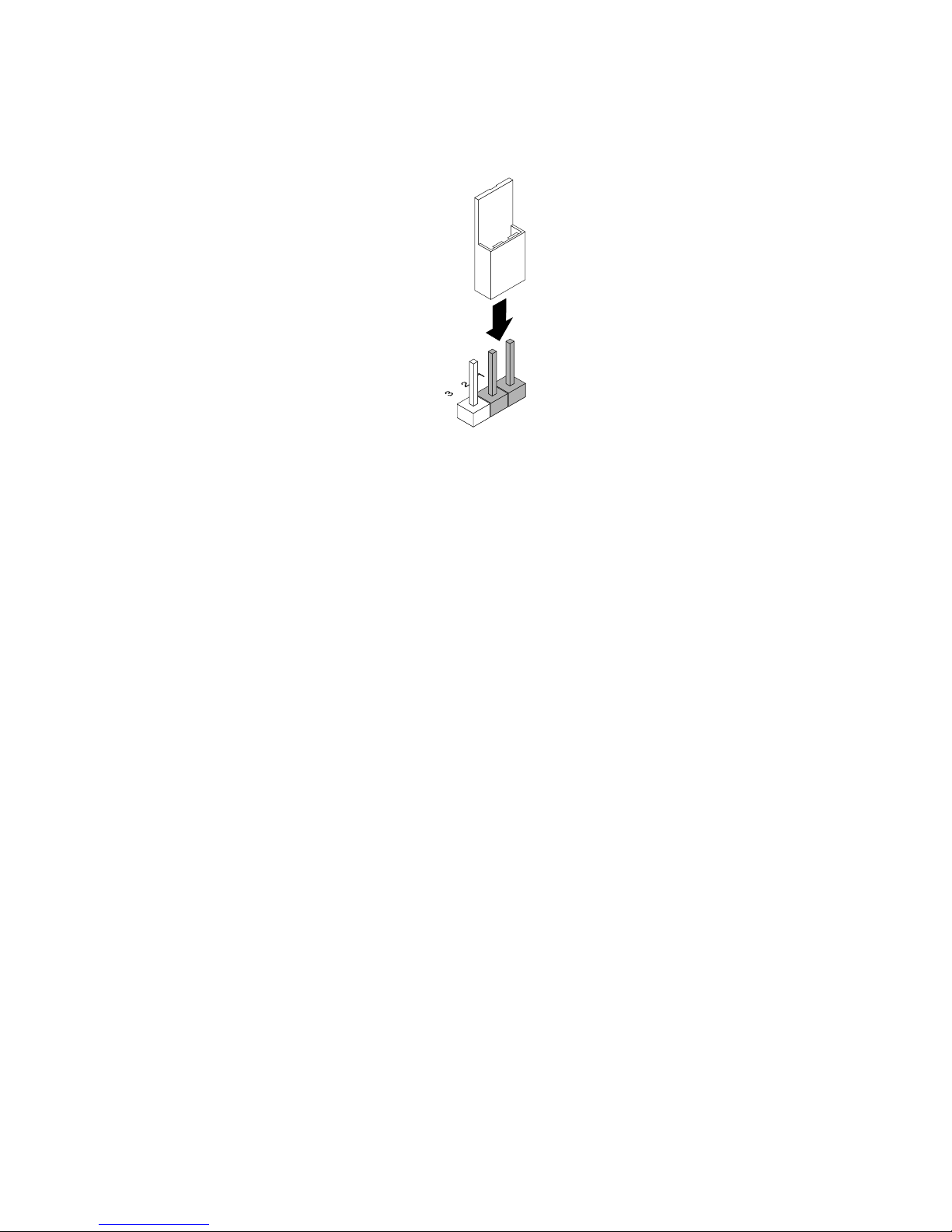
Thefollowingillustrationshowsajumperinthedefaultsettingposition(pin1andpin2).Thisisthecorrect
positionfornormaloperation.
Figure28.Defaultjumpersetting
Chapter3.Productoverview47
Page 60
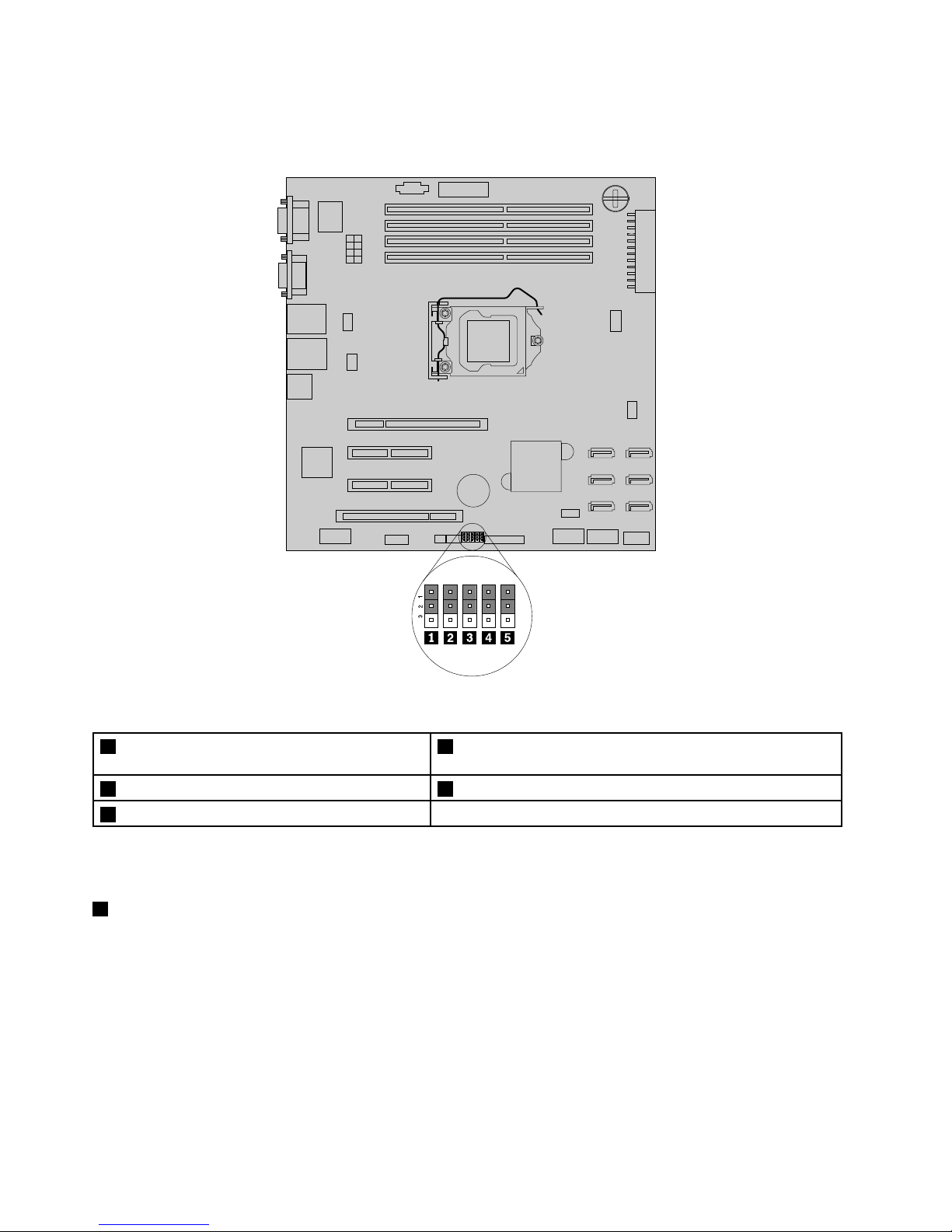
Thefollowingillustrationshowsthestatusofthejumpersonthesystemboardofyourserver.Youcan
congure,recover,enable,ordisablesomespecicfeaturesofthesystemboardbysettingthejumpers.
Figure29.Systemboardjumpers
1ClearCMOS(ComplementaryMetalOxide
Semiconductor)/Recoveryjumper
4Clearpasswordjumper
2BMCsettingjumper5Manufacturingjumper(reservedforthemanufacturer)
3BIOSrecoveryjumper
Attention:Tosetthejumpers,youneedtoopentheservercover.Donotopenyourserverorattemptany
repairbeforereadingandunderstandingthe“Safetyinformation”onpageiiiand“Guidelines”onpage83.
1ClearCMOS/Recoveryjumper
UsedtoclearCMOSandrecoveryourservertothefactorydefaultsettings.
Note:AfterclearingCMOS,allyourBIOSpasswordsareerasedandtheBIOSrecoverstothefactory
defaultsettings.
ToclearCMOS,dothefollowing:
1.Removeallmediafromthedrivesandturnoffallattacheddevicesandtheserver.Then,disconnectall
powercordsfromelectricaloutletsanddisconnectallcablesthatareconnectedtotheserver.
2.Removetheservercover.See“Removingtheservercover”onpage85.
48ThinkServerUserGuide
Page 61
3.Laytheserveronitssideforeasieroperation.
4.LocatetheClearCMOS/Recoveryjumperonthesystemboardandthenmovethejumperfromthe
defaultnormalposition(pin1andpin2)totheshort-circuitedposition(pin2andpin3).
5.Waitmorethan10secondsandthenmovetheClearCMOS/Recoveryjumperbacktothenormal
position(pin1andpin2).
6.Reinstalltheservercoverandconnectthepowercord(s).See“Completingthepartsreplacement”on
page162.
7.Waitabout30seconds.Then,turnontheserver.TheBIOSpasswordsareerasedandtheBIOS
recoverstothefactorydefaultsettings.
2BMCsettingjumper
WhentheBMCsettingjumperisinthedefaultnormalposition(pin1andpin2),theserverneedsabout30
secondsfortheBMCtoinitializewheneveryouconnecttheservertoanacpowersource.Ifyoupressthe
powerswitchonthefrontpanelduringthisperiod,theserverwillnotstartimmediately;itwillstartafter
theBMCinitializationnishes.
IfyoumovetheBMCsettingjumpertopin2andpin3,theserverwillbedirectlyturnedonwhenyoupressthe
powerswitchwithoutwaitingfortheBMCready.TheBMCfunctionmightnotbeavailableinthissituation.
3BIOSrecoveryjumper
SetthejumperandboottheserverfromaBIOSrecoveryimageinordertorecoveryourBIOSsettings.
TorecovertheBIOS,see“RecoveringfromaBIOSupdatefailure”onpage68
.
4Clearpasswordjumper
Usedtoeraseforgottenpasswords,suchasanadministratorpasswordandauserpassword.
Toclearpasswords,dothefollowing:
1.Removeallmediafromthedrivesandturnoffallattacheddevicesandtheserver.Then,disconnectall
powercordsfromelectricaloutletsanddisconnectallcablesthatareconnectedtotheserver.
2.Removetheservercover.See“Removingtheservercover”onpage85.
3.Laytheserveronitssideforeasieroperation.
4.LocatetheClearpasswordjumperonthesystemboardandthenmovethejumperfromthedefault
normalposition(pin1andpin2)totheshort-circuitedposition(pin2andpin3).
5.Waitmorethan10secondsandthenmovetheClearpasswordjumperbacktothenormalposition
(pin1andpin2).
6.Reinstalltheservercoverandconnectthepowercord(s).See“Completingthepartsreplacement”on
page162.
7.Waitabout30seconds.Then,turnontheserver.TheBIOSpasswordsareerased,includingthe
administratorpasswordanduserpassword.
8.T osetnewpasswords,see“Usingpasswords”onpage65.
5Manufacturingjumper
Reservedforthemanufacturer.
Chapter3.Productoverview49
Page 62
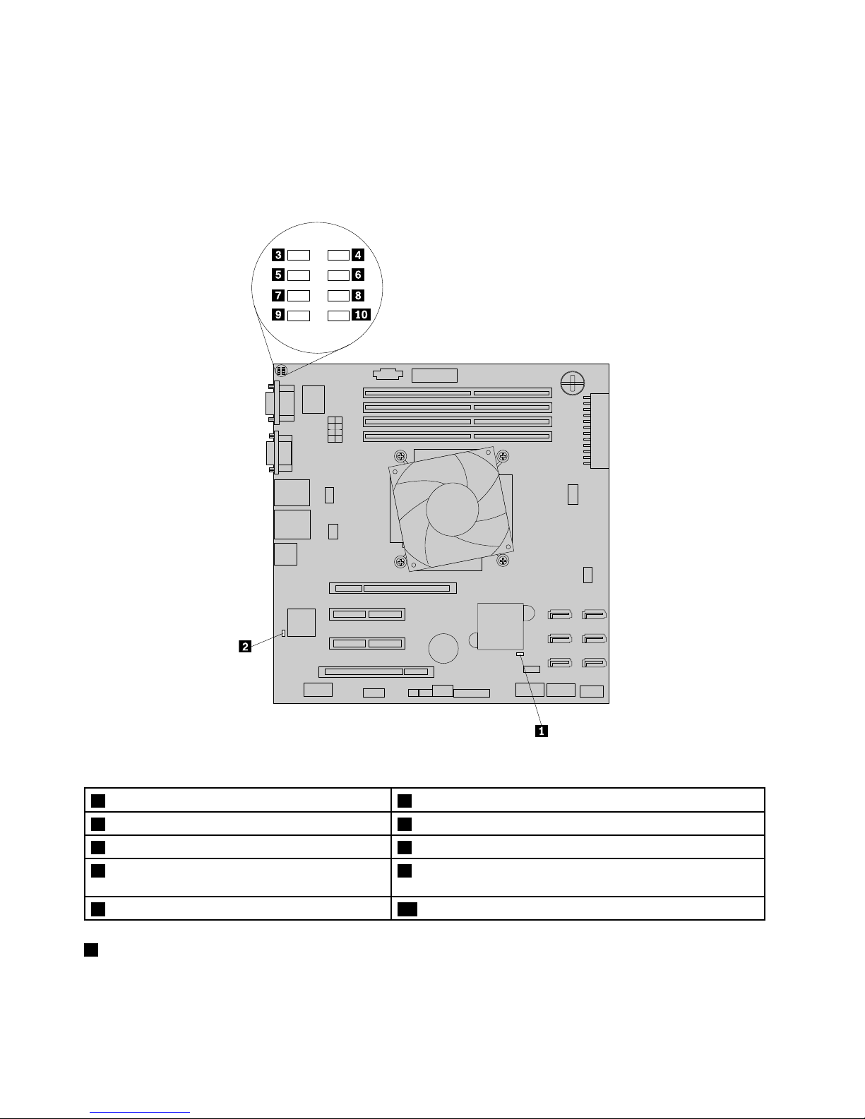
SystemboardLEDs
ThistopichelpsyoulocatetheLEDsonthesystemboard.
ThefollowingillustrationshowstheBMCstatusLED,systemboardhardwarefaultLED,andthePOSTcode
diagnosticLEDsonthesystemboard.
Figure30.SystemboardLEDs
1SystemboardhardwarefaultLED6POSTcodediagnosticLED#1
2BMCstatusLED7POSTcodediagnosticLED#6
3POSTcodediagnosticLED#48POSTcodediagnosticLED#2
4POSTcodediagnosticLED#0-LeastSignicant
Bit(LSB)
9POSTcodediagnosticLED#7-MostSignicantBit(MSB)
5POSTcodediagnosticLED#510POSTcodediagnosticLED#3
1SystemboardhardwarefaultLED
WhenthisLEDislit,itindicatesthatthesystemboardhardwarehasfailed.
50ThinkServerUserGuide
Page 63
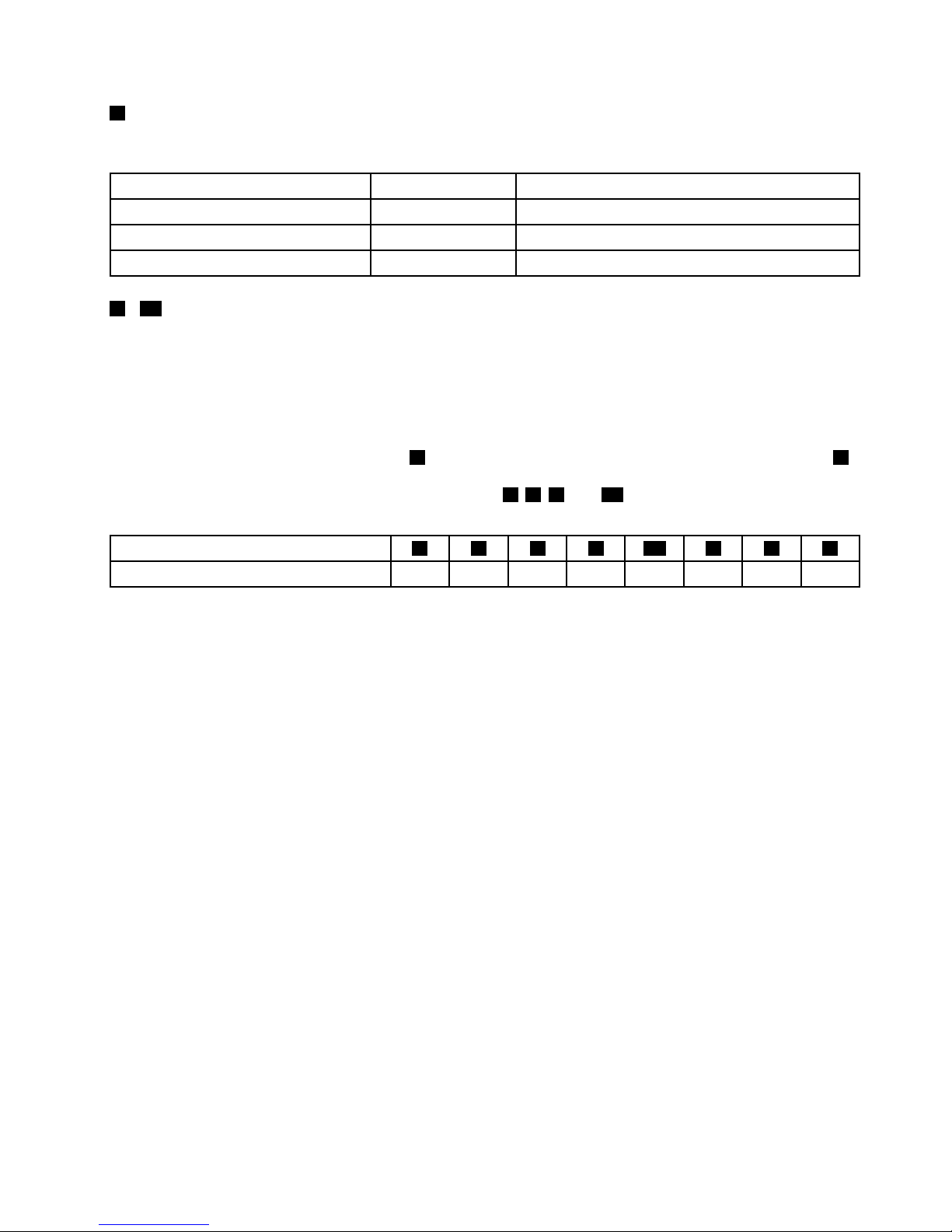
2BMCstatusLED
ThisLEDindicatestheBMCstatusofyourserver.
BMCstatusLEDColor
Description
OnGreenTheBMCisnotready.
Off
None
TheBMChasnopowerorfails.
Blinking
GreenTheBMCisworking.
3-10POSTcodediagnosticLEDs
Duringthesystembootprocess,theBIOSexecutesseveralplatformcongurationprocesses,eachof
whichisassignedaspecichexPOSTcodenumber.Wheneachcongurationroutineisstarted,theBIOS
displaysthePOSTcodenumberthroughthePOSTcodediagnosticLEDsonthesystemboard.Toassistin
troubleshootingasystemhangduringthePOSTprocess,thediagnosticLEDscanbeusedtoidentifythe
lastPOSTprocessexecuted.
ThePOSTcodediagnosticLED#0(callout4)istheLSBandthePOSTcodediagnosticLED#7(callout9)
istheMSB.IfaPOSTcodediagnosticLEDislit,itindicates1inthebinarynumeralsystem;otherwise,it
indicates0.Forexample,ifPOSTcodediagnosticLEDs
5,6,9,and10arelit,youcanreadthenumber
asthefollowing:
POSTcodediagnosticLED
975310864
Binarysymbol10101010
The“10101010”indicatesacorrespondingPOSTcode.FordetailedinformationaboutthePOSTcode,refer
totheHardwareMaintenanceManual.See“Serverdocumentation”onpage2forinformationaboutthe
HardwareMaintenanceManual.
Note:ThePOSTcodediagnosticLEDsandPOSTerrorcodeinformationareintendedfortrainedservice
personnelofLenovo.
Chapter3.Productoverview51
Page 64

52ThinkServerUserGuide
Page 65

Chapter4.T urningonandturningofftheserver
Thischapterprovidesinformationaboutturningonandturningofftheserver.
Turningontheserver
Theservercanbeturnedoninoneofthefollowingways:
•Afteryounishunpackingandsettinguptheserver,connectittoanacpowersource.Pressthepower
switchonthefrontpaneltoturnontheserver.See“Frontpanel”onpage17.Theserverneedsabout
30secondsfortheBMCtoinitializewheneveryouconnecttheservertoanacpowersource.Ifyou
pressthepowerswitchonthefrontpanelduringthisperiod,theserverwillnotstartimmediately;itwill
startaftertheBMCinitializationnishes.
•WhentheWakeonLANfeatureisenabledontheserverthatisconnectedtoanacpowersourceanda
LAN,anetworkadministratorcanremotelyturnonorwakeuptheserverfromamanagementconsole
usingremotenetworkmanagementsoftware.
•YoucanalsousetherelatedBMCfeaturetoremotelyturnontheserverthroughthemanagementLAN.
Turningofftheserver
CAUTION:
Thepowercontrolbuttononthedeviceandthepowerswitchonthepowersupplydonotturnoff
theelectricalcurrentsuppliedtothedevice.Thedevicealsomighthavemorethanonepower
cord.Toremoveallelectricalcurrentfromthedevice,ensurethatallpowercordsaredisconnected
fromthepowersource.
Theservercanbeturnedoffinoneofthefollowingways:
•Turnofftheserverfromtheoperatingsystemifyouroperatingsystemsupportsthisfeature.Afteran
orderlyshutdownoftheoperatingsystem,theserverwillturnoffautomatically.Forinstructionsonhow
toshutdownyourspecicoperatingsystem,refertotherelateddocumentationorhelpsystemfor
theoperatingsystem.
•Pressthepowerswitchonthefrontpaneltostartanorderlyshutdownoftheoperatingsystemandturn
offtheserver,ifyouroperatingsystemsupportsthisfeature.
•Ifyourserverstopsrespondingandyoucannotturnitoff,pressandholdthepowerswitchonthe
frontpanelforfoursecondsormore.Ifyoustillcannotturnofftheserver,disconnectallpowercords
fromtheserver.
•IftheserverisconnectedtoaLAN,anetworkadministratorcanremotelyturnofftheserverfroma
managementconsoleusingremotenetworkmanagementsoftware.
•YoucanalsousetherelatedBMCfeaturetoremotelyturnofftheserverthroughthemanagementLAN.
•Theservermightbeturnedoffasanautomaticresponsetoacriticalsystemfailure.
Notes:
1.Whenyouturnofftheserverandleaveitconnectedtoanacpowersource,theservercanalsorespond
toaremoterequesttoturnontheserver.Toremoveallpowerfromtheserver,youmustdisconnect
theserverfromtheacpowersource.
©CopyrightLenovo2011
53
Page 66

2.Forinformationaboutyourspecicoperatingsystem,refertotherelateddocumentationorhelpsystem
fortheoperatingsystem.
54ThinkServerUserGuide
Page 67

Chapter5.Conguringtheserver
Thischapterprovidesthefollowinginformationtohelpyouconguretheserver:
•“UsingtheSetupUtilityprogram”onpage55
•“UsingtheThinkServerEasyStartupprogram”onpage69
•“ConguringRAID”onpage71
•“ConguringtheEthernetcontrollers”onpage81
•“Updatingthermware”onpage81
UsingtheSetupUtilityprogram
ThistopicprovidesinformationaboutusingtheSetupUtilityprogram.
TheSetupUtilityprogramispartoftheserverrmware.YoucanusetheSetupUtilityprogramtoviewand
changethecongurationsettingsofyourserver,regardlessofwhichoperatingsystemyouareusing.
However,theoperatingsystemsettingsmightoverrideanysimilarsettingsintheSetupUtilityprogram.
StartingtheSetupUtilityprogram
ThistopicprovidesinstructionsonhowtostarttheSetupUtilityprogram.
TostarttheSetupUtilityprogram,dothefollowing:
1.Connecttheservertoanacpowersourceandpressthepowerswitchonthefrontpaneltoturnonthe
server.See“Turningontheserver”onpage53
.
2.PresstheF1keyassoonasyouseethelogoscreen.Then,waitforseveralseconds,andtheSetup
Utilityprogramopens.Ifyouhavesetapassword,youneedtotypethecorrectpasswordtoenterthe
SetupUtilityprogram.Forpasswordinformation,see“Usingpasswords”onpage65.
ViewinginformationintheSetupUtilityprogram
TheSetupUtilityprogrammenulistsvariousitemsaboutthesystemconguration.Selectadesireditem
toviewinformationorchangesettings.
WhenworkingwiththeSetupUtilityprogram,youmustusethekeyboard.Thekeysusedtoperformvarious
tasksaredisplayedontherightbottompaneofeachscreen.YoucanalsopresstheF1keyforgeneralhelp
aboutthekeys.Formostitems,thecorrespondinghelpmessageisdisplayedontherighttoppaneofthe
screenwhentheitemisselected.Iftheitemhassubmenus,youcandisplaythesubmenusbypressingEnter.
YoucanviewthefollowinginformationaboutyourspecicservermodelfromtheSetupUtilityprogram:
•TheMainmenulistsinformationabouttheBIOSversion,microprocessortypeandcorefrequency,
memorysize,andsystemdateandtime.
•OntheAdvancedmenu:
–SelectProcessorCongurationtoviewtheinformationabouttheinstalledmicroprocessorand
itssupportedtechnologies.
–SelectMemoryCongurationtoviewtheinformationabouttheinstalledmemorymodules.
–SelectSA TAConguration.Then,selectthedesiredSATAportfromSA TAPort0toSAT APort5toview
theinformationabouttheinstalledSATAdevices,suchasaSATAharddiskdriveoranopticaldrive.
©CopyrightLenovo2011
55
Page 68

•OntheServerManagementmenu,selectSystemInformationtoviewtheinformationaboutyour
system,includingtheBMCinformation.
SetupUtilityprograminterface
ThistopicprovidesinformationaboutthemenusanditemsintheSetupUtilityprogram.
DependingontheversionofyoursystemBIOS,somemenuoriteminformationmightdifferslightlyfromthe
informationinthistopic.Theinformationinthistopicisbasedonthe0.9bversionoftheBIOS.
Notes:
1.Thedefaultsettingsarealreadyoptimizedforyou.Usethedefaultvalueforanyitemyouarenotfamiliar
with.Donotchangethevalueofunfamiliaritemsoritemsthatarenotmentionedinthistopictoavoid
unexpectedproblems.Ifyouconsiderchangingtheserverconguration,proceedwithextremecaution.
Settingthecongurationincorrectlymightcauseunexpectedresults.Ifyoucannotturnontheserver
becauseofincorrectBIOSsettings,usetheClearCMOS/RecoveryjumpertorecovertheBIOStothe
factorydefaultsettingsorusetheBIOSrecoveryjumpertoboottheserverfromaBIOSrecoveryimage
andrecovertheBIOStotheversionintheimage.See“Systemboardjumpers”onpage46
.
2.LenovoprovidestheBIOSupdateutilityontheLenovoSupportWebsite.Y oucandownloadtheBIOS
imageandfollowtheinstructionsontheWebsitetoupdatetheBIOS.See“Updatingorrecoveringthe
BIOS”onpage67.AfterupdatingtheBIOS,alltheBIOSsettingsbecomethedefaultsettingsofthe
updatedBIOSversion.YouneedtocheckandreconguretheBIOSsettingsforyourspecicneeds.
3.Ifyouhavechangedanyhardwareintheserver,youmightneedtoreashtheBIOS,theBMCrmware,
andtheFRU/SDR.
ThefollowingmenusarelistedontheBIOSSetupUtilityscreen:
•Main:See“Mainmenu”onpage56
.
•Advanced:See“Advancedmenu”onpage57.
•Security:See“Securitymenu”onpage60.
•ServerManagement:See“ServerManagementmenu”onpage61.
•BootOptions:See“BootOptionsmenu”onpage62
.
•BootManager:See“BootManagermenu”onpage64.
•Exit:“Exitmenu”onpage64.
Mainmenu
AfterenteringtheSetupUtilityprogram,youcanseetheMainmenu,whichlistssomebasicinformation
aboutthesystemBIOSversionandbuilddate,themicroprocessor,memory,andthesystemdateandtime.
56ThinkServerUserGuide
Page 69
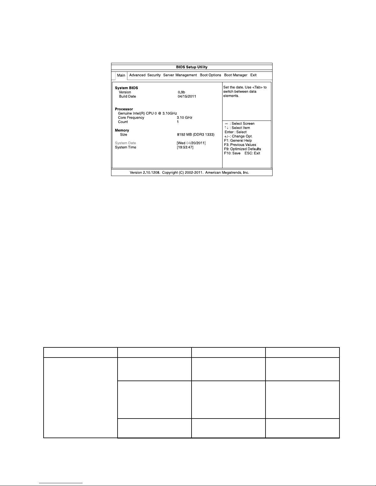
ThefollowingillustrationshowsanexampleoftheMainmenuintheSetupUtilityprogram.
Figure31.AnexampleoftheMainmenuintheSetupUtilityprogram
TosetthesystemdateandtimeontheMainmenu,see“Settingthesystemdateandtime”onpage64
.
Advancedmenu
ThistopicprovidesinformationaboutthevariouscongurationmenusanditemsontheAdvancedmenu
intheSetupUtilityprogram.
YoucanvieworchangevariousservercomponentsettingsontheAdvancedmenu.Thefollowingtable
showsthecontentsoftheAdvancedmenu.Oneachsubmenu,presstheEnterkeytoshowselectable
optionsandselectadesiredoptionbyusingupanddownarrowkeysortypedesiredvaluesfromthe
keyboarddirectly.Someitemsaredisplayedonthemenuonlyiftheserversupportsthecorresponding
features.
Notes:
•Enabledmeansthatthefunctioniscongured.
•Disabledmeansthatthefunctionisnotcongured.
•DefaultvaluesareinboldfaceintheSelectionscolumn.
Advancedmenuitems
Menuitem
SubmenuitemSelectionsComments
IntelHyper- Threading
Technology
•Disabled
•Enabled
Enableordisablethe
IntelHyper- Threading
Technology.
ActiveProcessorCores
•All
•1
•2
•3
Settheactive
microprocessorcores.
IntelVirtualization
Technology
•Disabled
•Enabled
EnableordisabletheIntel
VirtualizationTechnology.
ProcessorConguration
(setthemicroprocessor
congurationparameters)
Chapter5.Conguringtheserver57
Page 70

Menuitem
SubmenuitemSelectionsComments
IntelEISTTechnology
•Disabled
•Enabled
EnableordisabletheIntel
EISTTechnology.
P-StateCoordination
•HW_ALL
•SW_ALL
•SW_ANY
ChangetheP-State
Coordinationtype.
IntelT urboBoost
Technology
•Disabled
•Enabled
EnableordisabletheIntel
TurboBoostTechnology.
C1ESupport
•Disabled
•Enabled
EnableordisabletheC1E
Support.
CPUC3Report
•Disabled
•ACPIC2
•ACPIC3
EnableordisabletheCPU
C3report.
CPUC6Report
•Disabled
•Enabled
EnableordisabletheCPU
C6report.
PackageCStateLimit•C0
•C1
•C6
•C7
•NoLimit
SetthePackageCstate
limit.
HardwarePrefetcher
•Disabled
•Enabled
Enableordisablethe
hardwareprefetcher
function.
AdjacentCacheLine
Prefetch
•Disabled
•Enabled
Enableordisablethe
adjacentcacheline
prefetcherfunction.
MemoryConguration
(setmemoryconguration
parametersandview
informationaboutthe
installedmemorymodules)
MemoryReset•No
•Yes
Setthememorymodule
resetoptions.Ifamemory
moduleencountersany
errors,setthisoptionto
Yestotrytore-initializethe
memorymodule.
IntelVT-dTechnology•Disabled
•Enabled
EnableordisabletheIntel
VT-dtechnology.
IntelTXTTechnology•Disabled
•Enabled
Enableordisablethe
IntelTrustedExecution
Technology(TXT).
SerialPort1
•Disabled
•Enabled
Enableordisabletheserial
port1(COM1).
SerialPort2
•Disabled
•Enabled
Enableordisabletheserial
port2(COM2).
PoweronbyRTCAlarm
•Disabled
•Enabled
Enableordisablepowering
onbyRTCalarm.
ChipsetConguration
(setchipsetconguration
parameters)
RestoreonACPowerLoss•Stayoff
•LastState
Selectthesystemresume
statusafteracpowerloss.
58ThinkServerUserGuide
Page 71

Menuitem
SubmenuitemSelectionsComments
•Poweron
Ifthepowerisinterrupted
whentheserverison,after
thepowerresumes:
•IfyouhaveselectedStay
off,theserverwillstayin
theoffstate.
•IfyouhaveselectedLast
State,theserverwill
resumetothelaststate.
•Ifyouhaveselected
Poweron,theserverwill
restartautomatically.
SATAMode
•IDEMode
•AHCIMode
•RAIDMode
SelectSATAcontroller
operationmode.Ifyou
wanttocongureRAID,
chooseRAIDModeforthe
SATAcontroller.
SATAPort0
Viewtheinformationabout
theSATAdeviceconnected
totheSATAconnector0on
thesystemboard.
SATAPort1
Viewtheinformationabout
theSATAdeviceconnected
totheSATAconnector1on
thesystemboard.
SATAPort2
Viewtheinformationabout
theSATAdeviceconnected
totheSATAconnector2on
thesystemboard.
SATAPort3
Viewtheinformationabout
theSATAdeviceconnected
totheSATAconnector3on
thesystemboard.
SATAPort4
Viewtheinformationabout
theSATAdeviceconnected
totheSATAconnector4on
thesystemboard.
SATAConguration
(setSATAconguration
parameters)
SATAPort5
Viewtheinformationabout
theSATAdeviceconnected
totheSATAconnector5on
thesystemboard.
OnboardGraphics
Controller
•Disabled
•Enabled
Enableordisable
theonboardgraphics
controller.
PrimaryGraphics•Onboard
•Add-On
Chooseamodeforprimary
graphics.TheAdd-On
optionrequiresagraphics
cardinstalled.
OnboardLAN1I/OROM
•Disabled
•Enabled
Enableordisablethe
onboardLAN1I/OROM.
PCIConguration(setPCI
congurationparameters)
Chapter5.Conguringtheserver59
Page 72

Menuitem
SubmenuitemSelectionsComments
OnboardLAN2I/OROM
•Disabled
•Enabled
Enableordisablethe
onboardLAN2I/OROM.
PCIROMPriority•LegacyROM
•EFICompatibleROM
Chooseamodeforthe
PCIROMpriority.Incase
ofmultipleOptionROMs
(LegacyROMandEFI
CompatibleROM),the
selectionspecieswhich
PCIOptionROMtolaunch.
USBController
•Disabled
•Enabled
EnableordisabletheUSB
controller.
LegacyUSBSupport
•Enabled
•Disabled
•Auto
Enableordisablethe
supportonlegacyUSB
devices.
Port60/64Emulation
•Disabled
•Enabled
Enableordisablethe
port60h/64hemulation.
Thisfunctionisforthe
operatingsystemthatdoes
notsupportlegacyUSB
devices.
USBConguration
(setUSBconguration
parameters)
TANDBERGRDX3040
•Auto
•Floppy
•ForcedFDD
•HardDisk
•CD-ROM
Massstoragedevice
emulationtype.Auto
meanstoenumerate
devicesaccordingtotheir
mediaformat.Optical
devicesareemulatedas
“CD-ROM”;driveswith
nomediaareemulated
accordingtothedrivetype.
ConsoleRedirection
Conguration(setconsole
redirectionconguration
parameters)
ConsoleRedirection
•Disabled
•SerialPort1
•SerialPort2
Thesettingspecieshow
thehostcomputerandthe
remotecomputer(whichthe
userisusing)willexchange
data.Bothcomputers
shouldhavethesameor
compatiblesettings.
Securitymenu
ThistopicprovidesinformationaboutthesecurityrelatedsettingsontheSecuritymenuintheSetup
Utilityprogram.
Youcansetpasswords,theTPMfeature,andothersecurityfeaturesontheSecuritymenu.Thefollowing
tableshowsthecontentsoftheSecuritymenu.Foreachmenuitem,presstheEnterkeytoshowselectable
optionsandselectadesiredoptionbyusingupanddownarrowkeysortypedesiredvaluesfromthe
keyboarddirectly.Someitemsaredisplayedonthemenuonlyiftheserversupportsthecorresponding
features.
Notes:
•Enabledmeansthatthefunctioniscongured.
•Disabledmeansthatthefunctionisnotcongured.
•DefaultvaluesareinboldfaceintheSelectionscolumn.
60ThinkServerUserGuide
Page 73

Securitymenuitems
Menuitem
SelectionsComments
SetAdministratorPasswordSetanadministratorpassword
toprotectagainstunauthorized
accesstoyourserver.See“Using
passwords”onpage65
.
SetUserPasswordSetauserpasswordtoprotect
againstunauthorizedaccesstoyour
server.See“Usingpasswords”on
page65
.Thisitemisonlyavailable
afteryouhavesetanadministrator
password.
Power/ResetButtonLockout
•Disabled
•Enabled
IfthisitemissettoEnabled,the
powerswitchonthefrontpanelwill
belockedandtheservercanonlybe
turnedonremotely.
BIOSWriteProtect
•Disabled
•Enabled
Ifyouwanttoupdateorashthe
BIOS,makesurethatthisitemis
settoDisabled.Ifthisitemissetto
Enabled,theBIOSwillbeprotected
fromupdatingorashing.
TPMSupport
•Disabled
•Enabled
EnableordisabletheTPMsupport.
TousetheTPMfeature,youneedto
haveaTPMmoduleinstalledinthe
TPMconnectoronthesystemboard.
TPMState
•Disabled
•Enabled
ThisitemisdisplayedwhentheTPM
SupportissettoEnabled.Setthe
TPMStatetoenableordisablethe
TPMfunction.Theserverwillrestart
inordertochangethestateofTPM.
ServerManagementmenu
ThistopicprovidesinformationaboutthefeaturesavailableontheServerManagementmenuinthe
SetupUtilityprogram.
YoucanviewsysteminformationandvieworchangeeventlogsettingsontheServerManagementmenu.
ThefollowingtableshowsthecontentsoftheServerManagementmenu.Oneachsubmenu,pressthe
Enterkeytoviewtheinformationorshowselectableoptionsandselectadesiredoptionbyusingupand
downarrowkeys.Someitemsaredisplayedonthemenuonlyiftheserversupportsthecorresponding
features.
Note:DefaultvaluesareinboldfaceintheSelectionscolumn.
Chapter5.Conguringtheserver61
Page 74
ServerManagementmenuitems
Menuitem
SubmenuitemSelectionsComments
SystemInformation
Viewtheinformationabout
yoursystem,includingthe
BMCversioninformation.
ClearallEventLogs
•Enabled
•Disabled
IfthisitemissettoEnabled,
theSELwillbecleared.
BMCLANConguration
CongurationSource•Static
•Dynamic
•DoNothing
SelecttocongureLAN
channel1parameters
staticallyordynamically
(DHCP).TheDoNothing
optionmeansthatBMC
networkparameterswill
notbemodiedduringthe
BIOSphase.
BootOptionsmenu
ThistopicprovidesinformationaboutthemenusanditemsontheBootOptionsmenuintheSetupUtility
program.
TheBootOptionsmenuprovidesaninterfacetohelpyouvieworchangetheserverstartupoptions,
includingthestartupsequenceandbootpriorityforvariousdevices.Changesinthestartupoptionstake
effectwhenyoustarttheserver.
Thestartupsequencespeciestheorderinwhichtheserverchecksdevicestondabootrecord.The
serverstartsfromtherstbootrecordthatitnds.Forexample,youcandeneastartupsequencethat
checksforadiscintheopticaldrive,thencheckstheharddiskdrive,andthenchecksanetworkdevice.
Forinformationaboutsettingthestartupsequenceorselectingastartupdevice,see“Selectingastartup
device”onpage66
.
Thefollowinglist,showingtheorderinwhichdeviceswillbestartedup,isalwaysdisplayed.Evendevices
thatarenotattachedtoorinstalledinyourserverarelisted.Foreachdevicethatisattachedtoorinstalledin
theserver,informationaboutitispresentedonthescreenafterthecolon.
1.UEFIDevice:
2.HardDiskDrive:
3.OpticalDiskDrive:
4.RemovableDevice:
5.NetworkDevice:
ThefollowingtableshowsthecontentsoftheBootOptionsmenu.Oneachsubmenu,presstheEnterkey
toshowselectableoptionsandselectadesiredoptionbyusingupanddownarrowkeys.Someitemsare
displayedonthemenuonlyiftheserversupportsthecorrespondingfeatures.
Notes:
•Enabledmeansthatthefunctioniscongured.
•Disabledmeansthatthefunctionisnotcongured.
•DefaultvaluesareinboldfaceintheSelectionscolumn.
BootOptionsmenuitems
62ThinkServerUserGuide
Page 75

Menuitem
SelectionsComments
BootOption#1
•UEFIDevice
•HardDiskDrive
•OpticalDiskDrive
•RemovableDevice
•NetworkDevice
Settherststartupdevice.
BootOption#2
•UEFIDevice
•HardDiskDrive
•OpticalDiskDrive
•RemovableDevice
•NetworkDevice
Setthesecondstartupdevice.
BootOption#3
•UEFIDevice
•HardDiskDrive
•OpticalDiskDrive
•RemovableDevice
•NetworkDevice
Setthethirdstartupdevice.
BootOption#4
•UEFIDevice
•HardDiskDrive
•OpticalDiskDrive
•RemovableDevice
•NetworkDevice
Setthefourthstartupdevice.
BootOption#5
•UEFIDevice
•HardDiskDrive
•OpticalDiskDrive
•RemovableDevice
•NetworkDevice
Setthefthstartupdevice.
UEFIBootDevicePriorityVariesdependingontheavailable
UEFIdevices.
Specifythestartuppriorityforallthe
availableUEFIdevices.
HardDiskDrivePriorityVariesdependingontheavailable
harddiskdrives.
Specifythestartuppriorityforallthe
availableharddiskdrives.
OpticalDiskDrivePriority
Variesdependingontheavailable
opticaldrives.
Specifythestartuppriorityforallthe
availableopticaldrives.
RemovableDevicePriorityVariesdependingontheavailable
removabledevices.
Specifythestartuppriorityforallthe
availableremovabledevices.
NetworkDevicePriorityVariesdependingontheavailable
networkdevices.
Specifythestartuppriorityforallthe
availablenetworkdevices.
QuietBoot
•Disabled
•Enabled
Enableordisablethequietboot
featuretodeterminewhetherthelogo
screenwillbedisplayedornotwhen
startingtheserver.
Chapter5.Conguringtheserver63
Page 76
Menuitem
SelectionsComments
BootupNum-Lock
•On
•Off
TurntheNum-Lockkeyonoroff.
POSTErrorPause
•Disabled
•Enabled
EnableordisablethePOSTerror
pausefeature.Whenthisfeature
issettoEnabled,thesystemwill
stoponthePOSTscreenifanyerror
occursduringthePOST.
BootManagermenu
ThistopicprovidesinformationabouttheBootManagermenuintheSetupUtilityprogram.
TheBootManagermenulistsallthebootabledevicesinstalledonyourserversystemboardandtheitems
listedvarydependingonyourservercongurationandinstalledoptiondevices.Ifyouselectadesired
devicelistedonthismenu,theserverwillstartfromthedeviceyouselect.
YoucanpressF12whenturningontheserverandselectatemporarystartupdevicedirectlyfromtheboot
deviceselectionwindow.See“Selectingastartupdevice”onpage66.
Exitmenu
ThistopicprovidesinformationabouttheExitmenuintheSetupUtilityprogram.
AfteryounishviewingorchangingsettingsintheSetupUtilityprogram,youcanchooseonedesiredaction
fromtheExitmenutosavechanges,discardchanges,loaddefaultvalues,andexittheprogram.The
followingtablelistseachitemontheExitmenuwithdescriptions.PressEntertoselecttheitemandthen
selectYeswhenpromptedtoconrmtheaction.ForinformationaboutexitingtheSetupUtilityprogram,
see“ExitingtheSetupUtilityprogram”onpage67
.
Exitmenuitems
Item
Comments
SaveChangesandExitSaveyoursettingsandexittheSetupUtilityprogram.
DiscardChangesandExitDiscardyoursettingsandexittheSetupUtilityprogram.
SaveChangesSaveyoursettings.
DiscardChanges
Discardyoursettingsandloadpreviousvalues.
LoadDefaultValues
Returntotheoptimizeddefaultsettings.
SaveasUserDefaultValuesSavethechangessofarasuserdefaultvalues.
LoadUserDefaultValues
Restoretheuserdefaultvaluesforalltheitems.
Settingthesystemdateandtime
ThistopicprovidesinstructionsonhowtosetthesystemdateandtimeintheSetupUtilityprogram.
TosetthesystemdateandtimeintheSetupUtilityprogram,dothefollowing:
1.StarttheSetupUtilityprogram.See“StartingtheSetupUtilityprogram”onpage55.
2.OntheMainmenu,selectSystemDateorSystemTime.
3.UsetheTabkeytoswitchbetweendataelementsandtypethenumbersfromthekeyboardtosetthe
systemdateandtime.
4.PressF10tosavesettingsandexittheSetupUtilityprogram.
64ThinkServerUserGuide
Page 77

Usingpasswords
ByusingtheSetupUtilityprogram,youcansetapasswordtopreventunauthorizedaccesstoyourserver.
Youdonothavetosetapasswordtouseyourserver.However,usingapasswordimprovescomputing
security.Ifyoudecidetosetapassword,readthefollowingtopics.
SetupUtilityprogrampasswordtype
ThefollowingtypesofpasswordsareavailableintheSetupUtilityprogram:
•Administratorpassword
Settinganadministratorpassworddetersunauthorizedusersfromchangingcongurationsettings.Ifyou
areresponsibleformaintainingthecongurationsettingsofseveralcomputers,youmightwanttoset
anadministratorpassword.Whenanadministratorpasswordisset,youarepromptedtotypeavalid
passwordeachtimeyoutrytoaccesstheSetupUtilityprogram.TheSetupUtilityprogramcannot
beaccesseduntilavalidpasswordistypedin.
•Userpassword(onlyavailablewhenyouhavesetanadministratorpassword)
Whenauserpasswordisset,theservercannotbeuseduntilavalidpasswordistypedin.
Note:Ifboththeadministratorpasswordanduserpasswordareset,youcantypeeitherpassword.
However,youmustuseyouradministratorpasswordtochangeanycongurationsettings.
Passwordconsiderations
Forsecurityreasons,itisrecommendedtouseastrongpasswordthatcannotbeeasilycompromised.
Notes:
1.TheSetupUtilityprogrampasswordsarenotcasesensitive.
2.TheserversupportsSetupUtilityprogrampasswordsthatconsistofupto20characters.
Tosetastrongpassword,usethefollowingguidelines:
•Haveatleasteightcharactersinlength
•Containatleastonealphabeticcharacterandonenumericcharacter
•Notbeyournameoryourusername
•Notbeacommonwordoracommonname
•Besignicantlydifferentfromyourpreviouspasswords
Besidesthealphabeticcharacters(a-z)andnumericcharacters(0-9),theserveralsosupportscharacters
typedusingspecialkeysonthekeyboardforapassword.Refertothehelpmessageonthescreenwhen
settingapasswordtodeterminethevalidspecialcharacters.
Setting,changing,ordeletingapassword
Thistopicprovidesinstructionsonhowtoset,change,ordeleteapasswordintheSetupUtilityprogram.
Toset,change,ordeleteapasswordintheSetupUtilityprogram,dothefollowing:
1.StarttheSetupUtilityprogram.See“StartingtheSetupUtilityprogram”onpage55.
2.OntheSecuritymenu,selectSetAdministratorPasswordtosetanadministratorpasswordorselect
SetUserPasswordtosetauserpassword.
Note:TheSetUserPasswordoptionisonlyavailablewhenyouhavealreadysetanadministrator
password.
Chapter5.Conguringtheserver65
Page 78

3.See“Passwordconsiderations”onpage65.Then,followtheinstructionsonthescreentosetor
changeapassword.
4.Ifyouwanttodeleteapassword,typeyourcurrentpassword.PressEnterwhenyouareprompted
totypeanewpassword.Then,pressEntertoconrmthenewpassword.Thepreviouspassword
willbecleared.
Note:Ifyoudeleteanadministratorpassword,theuserpasswordwillalsobedeleted.Forsecurity
reasons,itisrecommendedthatyoualwayssetapasswordforyourserver.
5.PressF10tosavesettingsandexittheSetupUtilityprogram.
Ifyouhaveforgottenthepassword,youcanusetheClearpasswordjumperonthesystemboardtoerase
thepassword.See“Systemboardjumpers”onpage46.Then,setanewpasswordfortheserver.
ConguringtheTPMfunction
TheTPMfunctionprovidesahardwaresecuritysolutiontoencryptdataandprotecttheserver.TheTPM
functionisonlyavailablewhenthereisaTPMmoduleinstalledinyourserver.See“InstallingtheTPM
module”onpage109
.YoucanpurchaseaTPMmodulefromLenovo.
AfterinstallingaTPMmodule,youneedtocheckiftheTPMfunctionisenabledintheSetupUtilityprogram.
ToenabletheTPMfunctionintheSetupUtilityprogram,dothefollowing:
1.StarttheSetupUtilityprogram.See“StartingtheSetupUtilityprogram”onpage55.
2.OntheSecuritymenu,selectTPMSupport.MakesurethattheTPMSupportissettoEnabled.
3.WhentheTPMSupportissettoEnabled,theTPMStateitemisdisplayed.SettheTPMStateto
Enabled.
4.PressF10tosavesettingsandexittheSetupUtilityprogram.Theserverwillrestartinordertoenable
theTPMfunction.
Selectingastartupdevice
Ifyourserverdoesnotstartupfromadesireddevicesuchasthediscorharddiskdriveasexpected,doone
ofthefollowingtoselectthestartupdeviceyouwant:
Note:Notalldiscs,harddiskdrives,orotherremovabledevicesarebootable.
•Toselectatemporarystartupdevice,dothefollowing:
Note:Selectingastartupdeviceusingthefollowingmethoddoesnotpermanentlychangethestartup
sequence.
1.T urnonorrestartyourserver.
2.Whenyouseethelogoscreen,pressF12todisplaythebootmenu.Thebootdeviceselection
windowopens.Ifyourserverisconnectedtoanetworkandyouwanttostartuptheserverfromthe
network,pressF10.
3.Inthebootdeviceselectionwindow,usetheupanddownarrowkeysonthekeyboardtoswitch
betweentheselections.PressEntertoselectthedeviceofyourchoice.Then,theserverwillstart
upfromtheselecteddevice.
•Tovieworpermanentlychangetheconguredstartupdevicesequence,dothefollowing:
1.StarttheSetupUtilityprogram.See“StartingtheSetupUtilityprogram”onpage55.
2.OntheBootOptionsmenu,followtheinstructionsonthescreentosetthestartupdeviceforBoot
Option#1toBootOption#5dependingonyourneeds.Youcanalsosetthebootpriorityforvarious
devices.See“BootOptionsmenu”onpage62.
66ThinkServerUserGuide
Page 79

3.PressF10tosavesettingsandexittheSetupUtilityprogram.Theserverwillfollowthestartupdevice
sequenceyouhaveseteachtimeyouturnontheserver.
ExitingtheSetupUtilityprogram
Afteryounishviewingorchangingsettings,pressEsctoreturntotheSetupUtilityprogrammaininterface.
Ifyouareonanestedsubmenu,pressEscrepeatedlyuntilyoureachthemaininterface.Then,youcan
dooneofthefollowing:
•IfyouwanttosavethenewsettingsandexittheSetupUtilityprogram,pressF10.Otherwise,your
changeswillnotbesaved.
•Ifyoudonotwanttosavethenewsettings,selectExit➙DiscardChangesandExit.
•Ifyouwanttoreturntothedefaultsettings,pressF9orselectExit➙LoadDefaultValues.
FormoreinformationabouttheExitmenuintheSetupUtilityprogram,see“Exitmenu”onpage64.
UpdatingorrecoveringtheBIOS
ThistopicprovidesinstructionsonhowtoupdatetheBIOSandhowtorecoverfromaPOSTandBIOS
updatefailure.
Systemprogramsarethebasiclayerofsoftwarebuiltintoyourserver.SystemprogramsincludethePOST,
theUEFIBIOS,theSetupUtilityprogram,andtheBMCrmware.ThePOSTisasetoftestsandprocedures
thatareperformedeachtimeyouturnonyourserver.TheUEFIBIOSisalayerofsoftwarethattranslates
instructionsfromotherlayersofsoftwareintoelectricalsignalsthattheserverhardwarecanexecute.Y ou
canusetheSetupUtilityprogramtovieworchangethecongurationsettingsofyourserver.See“Using
theSetupUtilityprogram”onpage55
.TheBMCrmwareworkstogetherwithaniKVMkeytoprovide
advancedservermanagementfeatures.
Yourserversystemboardhasamodulecalledelectricallyerasableprogrammableread-onlymemory
(EEPROM,alsoreferredtoasashmemory).YoucaneasilyupdatethePOST,theBIOSandBMC
rmware,andtheSetupUtilityprogrambystartingyourserverwithasystem-program-updatediscora
bootableUSBkey.
LenovomightmakechangesandenhancementstotheBIOSandBMCrmware.Whenupdatesarereleased,
theyareavailablefordownloadontheLenovoSupportWebsiteathttp://www.lenovo.com/support.
InstructionsforusingtheupdatesareavailableinaTXTlethatisincludedwiththeupdateles.You
candownloadaself-startingdiscimage(knownasanISOimage)fortheupdateprogramandcreatea
system-program-updatediscorcopyalllesintheBIOSupdatepackagetoabootableUSBkeyandstart
theserverfromtheUSBkey.
YoucanalsousetheFirmwareUpdaterprogramtohelpyoukeeptheserverrmwareup-to-date.See
“Updatingthermware”onpage81
.
DownloadingtheBIOSupdateutilityprogram
BeforeupdatingorrecoveringyourBIOS,youneedtodownloadaBIOSupdateutilityprogramfromthe
LenovoSupportWebsite.
TodownloadtheBIOSupdateutilityprogram,dothefollowing:
Note:LenovomaintainstheSupportWebsitebymakingchangesandimprovementsperiodically.The
actualproceduremightvaryslightlyfromwhatisdescribedinthistopic.
1.GototheLenovoSupportWebsiteat:
http://www.lenovo.com/support
Chapter5.Conguringtheserver67
Page 80

2.ClickDownload&Drivers➙ThinkServer.
3.Findtheproductnameandclickthemachinetypeofyourserver.Tondthemachinetypeinformation
onthechassis,see“Machinetype,model,andserialnumberlabel”onpage13.
4.LocatetheBIOSupdateutilityontheWebpageandthenclicktheversionnumberoftheBIOSupdate
utilityprogram.FollowtheinstructionsontheWebpagetodownloadtheISOimageorupdatepackage
andtheinstallationinstructionsinaTXTle.
5.IfyouwilluseanISOimagetoupdatetheBIOS,useanyCDorDVDburningsoftwaretocreatea
bootablediscwiththeISOimage.IfyouwilluseanupdatepackagetoupdatetheBIOS,extractthe
packagetoalocaldriveandcopyallthelestoabootableUSBkey.
6.PrinttheTXTlethatcontainstheinstallationinstructions.Youwillneedtheinstructionswhen
performingtheBIOSupdateorrecoveryprocedure.
Updating(ashing)theBIOS
Thistopicprovidesinstructionsonhowtoupdate(ash)theBIOS.
Notes:
1.UpdatetheBIOSonyourserveronlyifthenewerBIOSversionspecicallysolvesaproblemyou
have.WedonotrecommendBIOSupdatesforserversthatdonotneedit.Youcanviewtheupdated
informationforthenewBIOSversionintheinstallationinstructionsfortheBIOSupdateutilityprogram.
See“DownloadingtheBIOSupdateutilityprogram”onpage67
.
2.DowngradingtheBIOStoanearlierversionisnotrecommendedandmightnotbesupported.Anearlier
BIOSversionmightnotcontainthesupportforthelatestsystemcongurations.
3.IfthepowertoyourserverisinterruptedwhilethePOSTandBIOSisbeingupdated,yourserver
mightnotrestartcorrectly.MakesurethatyouperformtheBIOSupdateprocedureinanenvironment
withasteadypowersupply.Besides,makesurethatyourservercanrestartsuccessfullywithout
encounteringhardwareproblems.
4.IfyouhaveupdatedtheBIOSrmware,alltheBIOSsettingsbecomethedefaultsettingsoftheupdated
BIOSversion.Y ouneedtocheckandreconguretheBIOSsettingsforyourspecicneeds.You
cannotedownyourspecicBIOSsettingsbeforeupdatingtheBIOSforaneasierrecongurationin
thenewBIOSversion.
Toupdate(ash)theBIOS,dothefollowing:
1.DownloadaBIOSupdateutilityprogramanditsinstallationinstructionsfromtheLenovoSupport
Website.Then,makeabootablediscorabootableUSBkeyandprinttheTXTlethatcontainsthe
installationinstructions.See“DownloadingtheBIOSupdateutilityprogram”onpage67.
2.T urnontheserverandpresstheF1keyassoonasyouseethelogoscreentostarttheSetupUtility
program.See“StartingtheSetupUtilityprogram”onpage55.
3.OntheSecuritymenu,checktheBIOSWriteProtectsetting.Toupdate(ash)theBIOS,theBIOS
WriteProtectitemmustbesettoDisabled.
4.PressF10tosavesettingsandexittheSetupUtilityprogram.Then,followtheinstallationinstructionsto
update(ash)theBIOSusingadiscorUSBkey.
5.Thesystemwillrestartautomaticallyaftertheupdateprocessiscompleted.Checkandrecongure
theBIOSsettingsforyourspecicneedsbasedonyournoteorreferto“UsingtheSetupUtility
program”onpage55.
RecoveringfromaBIOSupdatefailure
IfthepowertoyourserverisinterruptedwhiletheBIOSisbeingupdated,yourservermightnotrestart
correctly.Ifthishappens,performthefollowingproceduretorecoverfromtheBIOSupdatefailure.
TorecoverfromaBIOSupdatefailure,dothefollowing:
68ThinkServerUserGuide
Page 81

1.DownloadaBIOSupdateutilityprogramanditsinstallationinstructionsfromtheLenovoSupport
Website.Then,makeabootablediscorabootableUSBkeyandprinttheTXTlethatcontainsthe
installationinstructions.See“DownloadingtheBIOSupdateutilityprogram”onpage67.
2.Removeallmediafromthedrivesandturnoffallattacheddevicesandtheserver.Then,disconnectall
powercordsfromelectricaloutletsanddisconnectallcablesthatareconnectedtotheserver.
3.Removetheservercover.See“Removingtheservercover”onpage85.
4.LocatetheBIOSrecoveryjumperonthesystemboard.See“Systemboardjumpers”onpage46.
5.RemoveanypartsordisconnectanycablesthatmightimpedeyouraccesstotheBIOSrecoveryjumper.
6.MovetheBIOSrecoveryjumperfromthenormalposition(pin1andpin2)totherecoveryposition
(pin2andpin3).
7.Reinstallanypartsorreconnectanycablesandreinstalltheservercover.See“Completingtheparts
replacement”onpage162.
8.ConnecttheservertoanacpowersourceandthenfollowtheinstallationinstructionsfortheBIOS
updateutilityprogramtostarttheserverfromtherecoveryimage.Therecoverywindowopens.
9.PressEntertostarttherecoveryprocess.Aftertherecoveryprocessiscompleted,yourserverwill
automaticallyturnoff.
10.Repeatstep2throughstep5.
11.MovetheBIOSrecoveryjumperbacktothenormalposition(pin1andpin2).
12.Reinstallanypartsorreconnectanycablesandreinstalltheservercover.See“Completingtheparts
replacement”onpage162.
13.Connecttheservertoanacpowersourceandturnontheserver.TheBIOSsettingsbecomethedefault
settingsoftheupdatedBIOSversion.YouneedtocheckandconguretheBIOSsettingsforyour
specicneeds.See“UsingtheSetupUtilityprogram”onpage55
.
UsingtheThinkServerEasyStartupprogram
ThistopicguidesyoutousetheThinkServerEasyStartupprogramtosetupandcongureyourserver.
TheThinkServerEasyStartupprogramsimpliestheprocessofconguringRAIDandinstallingsupported
WindowsandLinuxoperatingsystemsanddevicedriversonyourserver.Theprogramworksinconjunction
withyourWindowsorLinuxoperatingsysteminstallationdisctoautomatetheprocessofinstallingthe
operatingsystemandassociateddevicedrivers.Thisprogramisprovidedwithyourserveronaself-starting
(bootable)ThinkServerEasyStartupDVD.TheuserguidefortheprogramisalsoontheDVDandcanbe
accesseddirectlyfromtheprograminterface.
IfyoudonothaveaThinkServerEasyStartupDVDavailable,youcanalsodownloadanISOimagefromthe
LenovoSupportWebsiteandmakeadiscbyyourself.
TodownloadtheThinkServerEasyStartupprogramimageandburnitintoadisc,dothefollowing:
Note:LenovomaintainstheSupportWebsitebymakingchangesandimprovementsperiodically.The
actualproceduremightvaryslightlyfromwhatisdescribedinthistopic.
1.GototheLenovoSupportWebsiteat:
http://www.lenovo.com/support
2.ClickDownload&Drivers➙ThinkServer.
3.Findtheproductnameandclickthemachinetypeofyourserver.Tondthemachinetypeinformation
onthechassis,see“Machinetype,model,andserialnumberlabel”onpage13.
4.ClickEasySuitetoquicklylocatetheThinkServerEasyStartupprogramontheWebpage.
Chapter5.Conguringtheserver69
Page 82

5.ClicktheversionnumberoftheThinkServerEasyStartupprogramandthenfollowtheinstructionson
theWebpagetodownloadtheISOimageandinstallationinstructionsinaTXTle.
Note:TheWebpagefordownloadingtheThinkServerEasyStartupprogramalsocontainsdetailed
informationabouttheprogram,includinglimitationsandlistsofhintsandtips.
6.UseanyDVDburningsoftwaretocreateabootablediscwiththeISOimage.
7.PrinttheTXTlethatcontainstheinstallationinstructionsandfollowtheinstructionstostartthe
ThinkServerEasyStartupprogram.
FeaturesoftheThinkServerEasyStartupprogram
ThistopicliststhefeaturesoftheThinkServerEasyStartupprogram.
TheThinkServerEasyStartupprogramhasthefollowingfeatures:
•Containedinaself-starting(bootable)DVD
•Easy-to-use,language-selectableinterface
•Integratedhelpsystemanduserguide
•Automatichardwaredetection
•RAIDcongurationutility
•Devicedriversprovidedbasedontheservermodelanddetecteddevices
•Selectablepartitionsizeandlesystemtype
•Supportformultipleoperatingsystems
•Abilitytoinstalltheoperatingsystemanddevicedriversinanunattendedmodetosavetime
•AbilitytocreateareuseableresponselethatcanbeusedwithsimilarlyconguredLenovoserversto
makefutureinstallationsevenfaster
StartingtheThinkServerEasyStartupprogram
ThistopicprovidesinstructionsonhowtostarttheThinkServerEasyStartupprogram.Afteryoustartthe
programandenterthemaininterface,clickUserGuidefordetailedinformationabouthowtousethis
programtohelpyouconguretheserverandinstallanoperatingsystem.
TostarttheThinkServerEasyStartupprogram,dothefollowing:
1.InserttheThinkServerEasyStartupDVDintotheopticaldrive,settheopticaldriveastherststartup
device,andstartyourserverfromtheDVDintheopticaldrive.See“Selectingastartupdevice”on
page66
.
2.Waitfortheprogramtoload.Then,youwillbepromptedforthefollowingselections:
•Thelanguageinwhichyouwanttoviewtheprogram
•Thelanguageofthekeyboardlayoutyouwillbeusingwiththeprogram
Note:ThesupportedlanguagesandkeyboardlayoutsfortheThinkServerEasyStartupprogramare
German,English,Spanish,French,Italian,Dutch,Turkish,andJapanese.YourThinkServerEasyStartup
DVDmightbeEnglishonly.Inthiscase,thekeyboardlayoutshouldbeEnglish.
3.Afterselectingthelanguageandkeyboardlayout,clickOK.Then,youwillseeoneormorereminders
ormessagesaboutconguringstoragedevices.ClickNextuntilyouarepresentedwiththeLenovo
LicenseAgreement.ReadtheLenovoLicenseAgreementcarefully.Inordertocontinue,youmustagree
withtermsbyclickingAgree.Then,theDateandtimewindowopens.
4.SetthecurrentdateandtimeandclickOK.TheStartoptionwindowopens.
5.TheStartoptionwindowprovidesthefollowingselections:
70ThinkServerUserGuide
Page 83

•Continuetothemaininterface.
•Installtheoperatingsystemusingapre-existingresponsele.
•CongureRAIDusingapre-existingresponsele.
Readtheexplanationsonthescreenandselectadesiredoption.Then,followtheinstructionsonthe
screen.IfthisisthersttimeyouareusingtheThinkServerEasyStartupprogram,selecttheoptionto
continuetothemaininterfaceandviewthecompatibilitynotesanduserguide.
Notes:
1.FunctionalityandsupportedoperatingsystemsvarydependingontheversionoftheThinkServer
EasyStartupprogram.Fromthemaininterfaceoftheprogram,clickCompatibilitynotestoview
theinformationabouttheRAIDcontrollers,operatingsystems,andservercongurationssupported
bythespecicversionoftheprogramandclickUserGuidetoviewthevariousfunctionsandlearn
howtousetheprogram.
2.BeforeusingtheThinkServerEasyStartupprogramtoinstallanoperatingsystem,makesureany
externalstoragedevicesandberchannelsareconguredcorrectly.
TheThinkServerEasyStartupprogrammaininterfaceprovidesthefollowingmenusontheleftpaneof
thescreen:
•Home
Thismenuisthewelcomepagethatcontainssomegeneraldescriptionsabouttheprogramandthe
Lenovocopyrightandtrademarkstatements.
•Compatibilitynotes
ThismenuprovidesinformationabouttheRAIDcontrollers,operatingsystems,andservercongurations
supportedbytheversionoftheprogramyouareusing.
•UserGuide
Thismenuprovidesinformationaboutthefeaturesoftheprogramandinstructionsonhowtousethe
program.
•Hardwarelist
Thismenudisplaysalistofhardwaredevicesdetectedbytheprogram.
•CongureRAID
ThismenuguidesyoutocongureRAIDorviewthecurrentRAIDcongurationandmakechanges
ifneeded.
•Installoperatingsystem
Thismenudisplaysaseriesofchoicesandpromptstocollectinformationrequiredforoperatingsystem
installation,preparestheharddiskdriveforinstallation,andtheninitiatestheinstallationprocessusing
youroperatingsysteminstallationdisc.
•About
Thismenuprovidestheversioninformationandlegalnotices.
ConguringRAID
ThistopicprovidesinformationaboutRAIDandtheutilityprogramsthatareavailableforyoutocongure
RAID.
Thistopiccontainsthefollowingitems:
•“AboutRAID”onpage72
•“RAIDforyourserver”onpage73
Chapter5.Conguringtheserver71
Page 84

•“ConguringRAIDusingtheThinkServerEasyStartupprogram”onpage74
•“ConguringtheonboardSATAsoftwareRAID”onpage75
•“ConguringtheadvancedSATAorSAShardwareRAID”onpage80
AboutRAID
RAID,anacronymforRedundantArrayofIndependentDisks,isatechnologythatprovidesincreased
storagefunctionsandreliabilitythroughredundancy.Thisisachievedbycombiningmultipleharddiskdrives
intoalogicalunit,wheredataisdistributedacrossthedrivesinoneofseveralwayscalledRAIDlevels.
WhenagroupofindependentphysicalharddiskdrivesaresetuptouseRAIDtechnology,theyareina
RAIDarray.Thisarraydistributesdataacrossmultipleharddiskdrives,butthearrayappearstothehost
serverasonesinglestorageunit.CreatingandusingRAIDarraysprovideshighperformance,suchasthe
expeditedI/Operformance,becauseseveraldrivescanbeaccessedsimultaneously.
RAIDdrivegroupsalsoimprovedatastoragereliabilityandfaulttolerancecomparedtosingle-drivestorage
systems.Datalossresultingfromadrivefailurecanbepreventedbyreconstructingmissingdatafromthe
remainingdrives.
ThefollowinglistdescribessomeofthemostcommonlyusedRAIDlevels:
•RAID0:block-levelstripingwithoutparityormirroring
SimplestripesetsarenormallyreferredtoasRAID0.RAID0usesstripingtoprovidehighdata
throughput,especiallyforlargelesinanenvironmentthatdoesnotrequirefaulttolerance.RAID0hasno
redundancyanditprovidesimprovedperformanceandadditionalstoragewithoutfaulttolerance.Any
drivefailuredestroysthearrayandthelikelihoodoffailureincreaseswithmoredrivesinthearray.RAID
0doesnotimplementerrorchecking,soanyerrorisuncorrectable.Moredrivesinthearraymeans
higherbandwidth,butgreaterriskofdataloss.
RAID0requiresaminimumnumberoftwoharddiskdrives.
•RAID1:mirroringwithoutparityorstriping
RAID1usesmirroringsothatdatawrittentoonedriveissimultaneouslywrittentoanotherdrive.Thisis
goodforsmalldatabasesorotherapplicationsthatrequiresmallcapacitybutcompletedataredundancy.
RAID1providesfaulttolerancefromdiskerrorsorfailuresandcontinuestooperateaslongasatleast
onedriveinthemirroredsetisfunctioning.Withappropriateoperatingsystemsupport,therecanbe
increasedreadperformanceandonlyaminimalwriteperformancereduction.
RAID1requiresaminimumnumberoftwoharddiskdrives.
•RAID5:block-levelstripingwithdistributedparity
RAID5usesdiskstripingandparitydataacrossalldrives(distributedparity)toprovidehighdata
throughput,especiallyforsmallrandomaccess.RAID5distributesparityalongwiththedataandrequires
alldrivesbutonetobepresenttooperate;drivefailurerequiresreplacement,butthearrayisnot
destroyedbyasingledrivefailure.Upondrivefailure,anysubsequentreadoperationscanbecalculated
fromthedistributedparitysothatthedrivefailureismaskedfromtheenduser.Thearraywillhavedata
lossintheeventofaseconddrivefailureandisvulnerableuntilthedatathatwasonthefailingdriveis
rebuiltontoareplacementdrive.Asingledrivefailureinthesetwillresultinreducedperformanceof
theentiresetuntilthefailingdrivehasbeenreplacedandrebuilt.
RAID5requiresaminimumnumberofthreeharddiskdrives.
72ThinkServerUserGuide
Page 85

•RAID10:acombinationofRAID0andRAID1
RAID10consistsofstripeddataacrossmirroredspans.ARAID10drivegroupisaspanneddrive
groupthatcreatesastripedsetfromaseriesofmirroreddrives.RAID10allowsamaximumofeight
spans.YoumustuseanevennumberofdrivesineachRAIDvirtualdriveinthespan.TheRAID1
virtualdrivesmusthavethesamestripesize.RAID10provideshighdatathroughputandcompletedata
redundancybutusesalargernumberofspans.
RAID10requiresaminimumnumberoffourharddiskdrivesandalsorequiresanevennumberofdrives,
forexample,sixharddiskdrivesoreightharddiskdrives.
•RAID50:acombinationofRAID0andRAID5
RAID50usesdistributedparityanddiskstriping.ARAID50drivegroupisaspanneddrivegroupin
whichdataisstripedacrossmultipleRAID5drivegroups.RAID50worksbestwithdatathatrequires
highreliability,highrequestrates,highdatatransfers,andmedium-to-largecapacity.
Note:HavingvirtualdrivesofdifferentRAIDlevels,suchasRAID0andRAID5,inthesamedrivegroupis
notallowed.Forexample,ifanexistingRAID5virtualdriveiscreatedoutofpartialspaceinanarray,the
nextvirtualdriveinthearrayhastobeRAID5only.
RAID50requiresaminimumnumberofsixharddiskdrives.
FordetailedinformationaboutRAID,referto“IntroductiontoRAID”intheMegaRAIDSASSoftwareUser
GuideonthedocumentationDVDthatcomeswithyourserver.
RAIDforyourserver
ThistopicprovidesinformationabouttheRAIDsupportedbyyourserver.
YourserversupportsthefollowingtwotypesofRAIDcongurations:
•OnboardSATAsoftwareRAIDcongurationusingtheLSISoftwareRAIDCongurationUtility
program;andRAIDmanagementusingtheMegaRAIDStorageManagerprogram
TheonboardSATAsoftwareRAIDcontrollerisintegratedintheIntelC202chiponthesystemboard.Ifyour
serverhasSATAharddiskdrivesthatareconnectedtothesystemboard,youcanusetheLSISoftware
RAIDCongurationUtilityprogramtocongureRAID.YourserversupportsonboardSATAsoftwareRAID
levels0,1,and10.YoucanalsoactivateRAIDlevel5byinstallingaThinkServerSATASoftwareRAID5
activationkey.See“InstallingorremovingtheThinkServerSATASoftwareRAID5Key”onpage102
.
YoucaninstallandusetheMegaRAIDStorageManagerprogramtomanagetheRAIDarrayandRAID
controllerinanoperatingsystemenvironment.
Fordetailedinformation,see“ConguringtheonboardSATAsoftwareRAID”onpage75
.
Chapter5.Conguringtheserver73
Page 86

•AdvancedSAT A/SAShardwareRAIDcongurationusingtheWebBIOSCongurationUtility
program;andRAIDmanagementusingtheMegaRAIDStorageManagerprogramandtheMegaCLI
CongurationUtilityprogram(requiresaRAIDcard)
SomeservermodelscomewitharequiredRAIDcardtoprovideadvancedSATA/SAShardwareRAID
functionstotheserver.Y oucanalsopurchasetheRAIDcardfromLenovoandinstallitintoservermodels
thatsupporttheRAIDcardtogetadvancedSATA/SAShardwareRAIDfunctions.See“RAIDcard”on
page33
and“InstallingorremovingtheRAIDcard”onpage98formoreinformation.
Note:ForservermodelswithmorethanfourharddiskdrivesormodelsthatuseSASharddiskdrives,
theremustbeaRAIDcardinstalled.
TheRAIDcardprovidestheWebBIOSCongurationUtilityprogramtohelpyoucongureRAID
independentlyoftheoperatingsystem.YoucanalsoinstalltheMegaRAIDStorageManagerprogramand
theMegaCLICongurationUtilityprogramtohelpyoumanagetheRAIDarrayandRAIDcontrollerin
anoperatingsystemenvironment.ThesupportedRAIDlevelsareRAID0,1,and10.ToactivateRAID
5and50levels,youneedtoinstallaRAID5keyontheRAIDcard.See“Installingorremovingthe
ThinkServer9240-8iRAID5UpgradeKey”onpage100
.
Fordetailedinformation,see“ConguringtheadvancedSATAorSAShardwareRAID”onpage80.
Note:TheThinkServerEasyStartupprogramsimpliestheprocessofconguringsupportedRAIDand
installingsupportedoperatingsystemsanddevicedrivers.
BeforeconguringRAIDforyourserver,observethefollowingprecautions:
1.UseharddiskdrivesthathavethesamecapacitywithinasingleRAIDarray.
2.Useharddiskdrivesthatareofthesametype(SATAorSAS)withinasingleRAIDarray.
3.Dependingontheoperatingsystem,theprimaryRAIDmightbelimitedto2TBtotaldrivecapacity.
ConguringRAIDusingtheThinkServerEasyStartupprogram
TheThinkServerEasyStartupprogramsimpliestheprocessofconguringsupportedRAIDandinstalling
supportedWindowsandLinuxoperatingsystemsanddevicedriversonyourserver.Theuserguideforthe
programcanbeaccesseddirectlyfromtheprograminterface.
TheThinkServerEasyStartupprogramhasthefollowingfeaturesforRAIDconguration:
•ForusewithallsupportedRAIDcontrollers
•AutomaticallydetectshardwareandlistsallsupportedRAIDcongurations
•Conguresoneormorediskarrayspercontrollerdependingonthenumberofdrivesattachedtothe
controllerandtheRAIDlevelselected
•Supportshot-sparedrives
•CreatesaRAIDresponselethatcanbeusedtocongureRAIDcontrollersonsimilarlycongured
Lenovoservers
See“UsingtheThinkServerEasyStartupprogram”onpage69
andviewtheuserguidefromthemain
interfaceoftheprogram.
SomeRAIDmanagementsoftwareisalsoprovidedontheThinkServerEasyStartupDVDtohelpyoumanage
RAIDarraysandRAIDcontrollersinanoperatingsystemenvironment.Afteryouentertheoperatingsystem,
inserttheThinkServerEasyStartupDVDintotheopticaldrive.Theinstallationpackagesfortheprogramsare
locatedintheUtilitiesandOthersfolderintherootdirectoryoftheDVD.TheThinkServerEasyStartupDVDis
designedfordifferenttypesofserversandtheUtilitiesandOthersfoldermightcontainadditionalinstallation
packagesthatarenotrequiredtobeinstalledintoyourserver.Formoreinformation,see“Installingand
usingtheMegaRAIDStorageManagerprogram”onpage80
and“ConguringtheadvancedSATAorSAS
hardwareRAID”onpage80
.
74ThinkServerUserGuide
Page 87

ConguringtheonboardSATAsoftwareRAID
TheonboardSATAsoftwareRAIDcontrollerisintegratedintheIntelC202chiponthesystemboard.Ifyour
serverhasSATAharddiskdrivesthatareconnectedtothesystemboard,youcanusetheLSISoftware
RAIDCongurationUtilityprogramtocongureRAIDindependentlyoftheoperatingsystem.Yourserver
supportsonboardSATAsoftwareRAIDlevels0,1,and10.YoucanalsoactivateRAID5byinstalling
aThinkServerSATASoftwareRAID5activationkey.See“InstallingorremovingtheThinkServerSATA
SoftwareRAID5Key”onpage102
.
YoucaninstallandusetheMegaRAIDStorageManagerprogramtomanagetheRAIDarrayandRAID
controllerinanoperatingsystemenvironment.
StartingtheLSISoftwareRAIDCongurationUtilityprogram
ThistopicprovidesinstructionsonhowtostarttheLSISoftwareRAIDCongurationUtilityprogram.
TostarttheLSISoftwareRAIDCongurationUtilityprogram,dothefollowing:
1.StarttheSetupUtilityprogram.See“StartingtheSetupUtilityprogram”onpage55.
2.OntheAdvancedmenu,selectSATAConguration➙SATAMode.
3.SelectRAIDMode.Then,pressF10tosavesettingsandexittheSetupUtilityprogram.
4.Whenyouseethemessage“PressCtrl-MorEntertorunLSISoftwareRAIDSetupUtility,”immediately
pressCtrl+MorEntertostarttheLSISoftwareRAIDCongurationUtilityprogram.
LSISoftwareRAIDCongurationUtilityprograminterface
ThistopicprovidesinformationaboutthemenusanditemsintheLSISoftwareRAIDCongurationUtility
program.Dependingontheversionoftheprogram,somemenuoriteminformationmightdifferslightlyfrom
theinformationinthistopic.
WhenworkingwiththeLSISoftwareRAIDCongurationUtilityprogram,youmustusethekeyboard.
Thekeysusedtoperformvarioustasksaredisplayedonthebottomofeachscreen.Useupanddown
arrowkeystonavigatebetweenitems.Formostitems,thecorrespondinghelpmessageisdisplayed
onthebottomofthescreenwhentheitemisselected.Iftheitemhassubmenus,youcandisplaythe
submenusbypressingEnter.
Chapter5.Conguringtheserver75
Page 88
AfterenteringtheLSISoftwareRAIDCongurationUtilityprogram,youcanseetheManagementMenuon
thescreen.TheManagementMenucontainsthefollowingmenuitems:
•Congure
ThismenucontainsitemstohelpyoucreateaRAIDarray,viewthecurrentRAIDconguration,addanew
array,deleteanexistingarray,orselectabootvirtualdrive.
•Initialize
Thismenuhelpsyouinitializevirtualdrive(s).
Note:Initializingavirtualdriveerasesalldataonthevirtualdrive.Backupanydatayouwanttokeepand
ensuretheoperatingsystemisnotinstalledonthevirtualdrivebeforetheinitialization.
•Objects
ThismenuhelpsyoucongureparametersfortheRAIDadapterorcontroller,thevirtualdrive(s),andthe
physicaldrive(s).
•Rebuild
Thismenuhelpsyourebuildaphysicaldriveinanarrayintheeventofaphysicaldrivefailure.Youcan
choosetorebuildthedataonthefailingdriveifthedriveisstilloperational.Ifthedriveisnotoperational,
itmustbereplacedandthedataonthefailingdrivemustberebuiltonanewdrivetorestorethesystem
tofaulttolerance.Ifhot-sparedrivesareavailable,thefailingdrivemightberebuiltautomaticallywithout
anyuserintervention.
•CheckConsistency
Thismenuhelpsyoudoconsistencycheckforthevirtualdrive(s).Theconsistencycheckveriesthe
correctnessofthedataonvirtualdrive(s)thatuseRAID1,5,and10.
ThefollowingtableshowsthevariousmenusanditemsintheLSISoftwareRAIDCongurationUtility
program.Oneachmenu,presstheEnterkeytoshowselectableoptionsandselectadesiredoptionby
usingupanddownarrowkeysortypedesiredvaluesfromthekeyboarddirectly.
Menuitem
SubmenuitemComments
EasyCongurationCreatephysicalarrays.Anarraywill
automaticallybecomeavirtualdrive.
NewCongurationCleartheexistingcongurationand
startanewconguration.
View/AddConguration
Viewtheexistingcongurationoradda
newconguration.
ClearCongurationCleartheexistingconguration.
Congure
SelectBootDriveSelectabootvirtualdrive.
Initialize
Variesbyconguration.
Initializevirtualdrives.
Adapter
Setadapterrelatedparameters,such
asrebuildrate,consistencycheckrate,
auto-rebuild,andsoon.
VirtualDrive
Setvirtualdriveparameters.
Objects
PhysicalDrive
Setphysicaldriveparameters,suchas
creatingahot-sparedriveforthevirtual
drive,makingafailingdriveasonline,
changingadrivestate,andviewingthe
specicationsofaphysicaldrive.
Rebuild
Variesbyconguration.
Rebuildphysicaldrive(s).
CheckConsistency
Variesbyconguration.
Checkconsistencyofvirtualdrive(s).
76ThinkServerUserGuide
Page 89

Creating,adding,ordeletingaRAIDarray
Thistopicprovidesinstructionsonhowtocreate,add,ordeleteaRAIDarrayusingtheLSISoftwareRAID
CongurationUtilityprogram.
Note:BeforeyoucreateaRAIDarrayusingtheLSISoftwareRAIDCongurationUtilityprogram,makesure
thattheservermeetstherequiredhardwareconguration.Forexample,theserverneedstohavethe
requirednumberofSATAharddiskdrivesinstalledandconnectedtothesystemboard.See“AboutRAID”
onpage72
forinformationabouttherequirednumberofharddiskdrivesforeachRAIDlevel.Ifyouwantto
createaRAID5arrayusingtheLSISoftwareRAIDCongurationUtilityprogram,theserveralsoneedsto
haveaThinkServerSATASoftwareRAID5Keyinstalledonthesystemboard.See“Installingorremovingthe
ThinkServerSATASoftwareRAID5Key”onpage102
.
Tocreate,add,ordeleteaRAIDarrayusingtheLSISoftwareRAIDCongurationUtilityprogram,dothe
following:
1.StarttheLSISoftwareRAIDCongurationUtilityprogram.See“StartingtheLSISoftwareRAID
CongurationUtilityprogram”onpage75.
2.Onthemaininterfaceoftheprogram,dooneofthefollowingdependingonyourneeds:
•IfyouwanttocreateaRAIDarray,selectEasyCongurationandthenfollowtheinstructionson
thescreen.
•IfyouwanttoaddasecondaryRAIDconguration,selectView/AddCongurationandthenfollow
theinstructionsonthescreentoviewthecurrentcongurationandaddanewconguration.
•IfyouwanttodeletetheexistingRAIDconguration,exittheprogramandbackupallyourdataon
theharddiskdrives.Afterbackingupallyourdata,entertheprogrammaininterfaceandselectClear
Conguration.SelectYeswhenpromptedandfollowtheinstructionsonthescreen.
Attention:DeletingtheexistingRAIDcongurationerasesalldataonthevirtualdrive.Makesurethat
youbackupalldatabeforedeletingtheRAIDarray.Iftheoperatingsystemisinstalledonthevirtual
driveyouwanttodelete,youneedtoreinstalltheoperatingsystemaftercompletingtheoperation.
•IfyouwanttodeletetheexistingRAIDcongurationandmakeanewconguration,exittheprogram
andbackupallyourdataontheharddiskdrives.Afterbackingupallyourdata,entertheprogram
maininterfaceandselectNewConguration.SelectYeswhenpromptedtoproceedandthen
followtheinstructionsonthescreen.
Attention:DeletingtheexistingRAIDcongurationerasesalldataonthevirtualdrive.Makesurethat
youbackupalldatabeforedeletingtheRAIDarray.Iftheoperatingsystemisinstalledonthevirtual
driveyouwanttodelete,youneedtoreinstalltheoperatingsystemaftercompletingtheoperation.
Initializingavirtualdrive
ThistopicprovidesinstructionsonhowtoinitializeavirtualdriveusingtheLSISoftwareRAIDConguration
Utilityprogramaftercompletingthecongurationprocess.
Virtualdriveinitializationistheprocessofwritingzerostothedataeldsofavirtualdriveand,infault-tolerant
RAIDlevels,generatingthecorrespondingparitytoputthevirtualdriveinareadystate.Initializationerases
alldataonthevirtualdrive.Drivegroupswillworkwithoutbeinginitialized,buttheycanfailaconsistency
checkbecausetheparityeldshavenotbeengenerated.
Notes:
1.Makesurethatyoubackupanydatayouwanttokeepbeforeinitializingavirtualdrive.
2.Makesurethattheoperatingsystemisnotinstalledonthevirtualdriveyouareinitializing.Otherwise,
youneedtoreinstalltheoperatingsystemaftercompletingtheoperation.
ToinitializeavirtualdriveusingtheLSISoftwareRAIDCongurationUtilityprogram,dothefollowing:
Chapter5.Conguringtheserver77
Page 90

1.StarttheLSISoftwareRAIDCongurationUtilityprogram.See“StartingtheLSISoftwareRAID
CongurationUtilityprogram”onpage75.
2.Onthemaininterfaceoftheprogram,selectInitializeandfollowtheinstructionsonthescreen.
Settingahot-sparedrive
Thistopicprovidesinstructionsonhowtosetaphysicaldriveasahot-sparedriveusingtheLSISoftware
RAIDCongurationUtilityprogram.
Ahot-sparedriveisanextra,unuseddrivethatispartofthedisksubsystem.Itisusuallyinstandby
modeandreadyforserviceifadrivefails.Settinghot-sparedrivesenablesyoutoreplacefailingdrives
withoutperformingasystemshutdownoperation.Foradetailedintroductiontohot-sparedrives,referto
“IntroductiontoRAID”intheMegaRAIDSASSoftwareUserGuideonthedocumentationDVDthatcomes
withyourserver.
Tosetaphysicaldriveasahot-sparedriveusingtheLSISoftwareRAIDCongurationUtilityprogram,
dothefollowing:
1.StarttheLSISoftwareRAIDCongurationUtilityprogram.See“StartingtheLSISoftwareRAID
CongurationUtilityprogram”onpage75.
2.Dooneofthefollowing:
•IfyouwanttocreateoraddanewRAIDarray,youcansetahot-sparedriveduringtheconguration
processbyfollowingtheinstructionsonthescreen.
•Ifyouwanttosetahot-sparedriverightaftertheconguration,selectObjects➙PhysicalDrive
fromtheprogrammaininterface.Then,selectthephysicaldrivethatyouwanttosetasahot-spare
driveandpressEnter.Asubmenuisdisplayed.SelectMakeHotSparefromthesubmenuandthen
selectYeswhenpromptedtosetthephysicaldriveasahot-sparedrive.
Rebuildingaphysicaldrive
ThistopicprovidesinstructionsonhowtorebuildaphysicaldriveusingtheLSISoftwareRAIDConguration
Utilityprogramwhenaphysicaldriveinanarrayfails.
WhenadriveinaRAIDdrivegroupfails,youcanrebuildthedrivebyrecreatingthedatathatwasstoredon
thedrivebeforeitfails.Ifthedriveisnotoperational,itmustbereplacedandthedataonthefailingdrive
mustberebuiltonanewdrivetorestorethesystemtofaulttolerance.Ifhot-sparedrivesareavailable,the
failingdrivemightberebuiltautomaticallywithoutanyuserintervention.
TheRAIDcontrollerrecreatesthedatausingthedatastoredonotherdrivesinthedrivegroup.Rebuilding
canbedoneonlyindrivegroupswithdataredundancy,suchasRAID1,5,and10drivegroups.Fora
detailedintroductiontodiskrebuild,referto“IntroductiontoRAID”intheMegaRAIDSASSoftwareUser
GuideonthedocumentationDVDthatcomeswithyourserver.
TorebuildaphysicaldriveusingtheLSISoftwareRAIDCongurationUtilityprogramwhenaphysical
driveinanarrayfails,dothefollowing:
1.StarttheLSISoftwareRAIDCongurationUtilityprogram.See“StartingtheLSISoftwareRAID
CongurationUtilityprogram”onpage75.
2.Onthemaininterfaceoftheprogram,selectRebuildandfollowtheinstructionsonthescreen.
Note:Runningaconsistencycheckimmediatelyaftertherebuildcompletestoensuredataintegrityforthe
virtualdrives.See“Runningaconsistencycheck”onpage79.
Therebuildrateisthepercentageofthecomputingcyclesdedicatedtorebuildingfailingdrives.Arebuild
rateof100percentmeansthatthesystemgivesprioritytorebuildingthefailingdrives.Therebuildratecan
78ThinkServerUserGuide
Page 91

beconguredbetween0percentand100percent.At0percent,therebuildisdoneonlyifthesystemisnot
doinganythingelse.At100percent,therebuildhasahigherprioritythananyothersystemactivity.
ToconguretherebuildrateusingtheLSISoftwareRAIDCongurationUtilityprogram,dothefollowing:
Note:Usingarebuildrateof0or100percentisnotrecommended.Thedefaultvalueis30percent.
1.StarttheLSISoftwareRAIDCongurationUtilityprogram.See“StartingtheLSISoftwareRAID
CongurationUtilityprogram”onpage75
.
2.Onthemaininterfaceoftheprogram,selectObjects➙Adapter➙RebuildRate.
Note:UseupanddownarrowkeystonavigatebetweenitemsandpressEntertoselectanoption.
3.Settherebuildratebytypingadesiredvaluefromthekeyboarddirectly.
Runningaconsistencycheck
ThistopicprovidesinstructionsonhowtorunaconsistencycheckforvirtualdrivesusingtheLSISoftware
RAIDCongurationUtilityprogram.
AconsistencycheckisanoperationthatveriesthatallstripesonavirtualdrivewitharedundantRAID
levelareconsistent.Theconsistencycheckoperationveriescorrectnessofthedataonvirtualdrivesthat
useRAID1,5,and10(RAID0doesnotprovidedataredundancy).Forexample,inasystemwithparity,
checkingconsistencymeanscomputingthedataononedriveandcomparingtheresultstothecontentsof
theparitydrive.
Youshouldrunaconsistencycheckonfault-tolerantvirtualdrivesperiodically.Itisrecommendedthatyou
runaconsistencycheckatleastonceamonth.Youmustrunaconsistencycheckifyoususpectthatthe
virtualdrivedatamightbecorrupted.Besuretobackupthedatabeforerunningaconsistencycheckifyou
suspectthedatamightbecorrupted.
TorunaconsistencycheckusingtheLSISoftwareRAIDCongurationUtilityprogram,dothefollowing:
1.StarttheLSISoftwareRAIDCongurationUtilityprogram.See“StartingtheLSISoftwareRAID
CongurationUtilityprogram”onpage75
.
2.Onthemaininterfaceoftheprogram,selectCheckConsistencyandfollowtheinstructionsonthe
screen.
Theconsistencycheckrateistherateatwhichconsistencycheckoperationsarerunonasystem.The
consistencycheckratecanbeconguredbetween0percentand100percent.At0percent,theconsistency
checkisdoneonlyifthesystemisnotdoinganythingelse.At100percent,theconsistencycheckhasa
higherprioritythananyothersystemactivity.
ToconguretheconsistencycheckrateusingtheLSISoftwareRAIDCongurationUtilityprogram,do
thefollowing:
Note:Usingaconsistencycheckrateof0or100percentisnotrecommended.Thedefaultvalueis30
percent.
1.StarttheLSISoftwareRAIDCongurationUtilityprogram.See“StartingtheLSISoftwareRAID
CongurationUtilityprogram”onpage75.
2.Onthemaininterfaceoftheprogram,selectObjects➙Adapter➙ChkConstRate.
Note:UseupanddownarrowkeystonavigatebetweenitemsandpressEntertoselectanoption.
3.Settheconsistencycheckratebytypingadesiredvaluefromthekeyboarddirectly.
Chapter5.Conguringtheserver79
Page 92

InstallingandusingtheMegaRAIDStorageManagerprogram
YoucaninstallandusetheMegaRAIDStorageManagerprogramtomanagetheRAIDarrayandRAID
controllerinanoperatingsystemenvironmentafterconguringRAID.
TheinstallationpackagefortheMegaRAIDStorageManagerprogramisontheThinkServerEasyStartup
DVD.Afteryouentertheoperatingsystem,inserttheThinkServerEasyStartupDVDintotheopticaldrive.
TheinstallationpackagefortheMegaRAIDStorageManagerprogramislocatedintheUtilitiesandOthers
folderintherootdirectoryoftheDVD.
ToinstallandusetheMegaRAIDStorageManagerprogram,refertothefollowingchaptersintheMegaRAID
SASSoftwareUserGuideonthedocumentationDVDthatcomeswithyourserver:
Note:SomeinformationinthesechaptersmightbeintendedfortheadvancedSATA/SAShardwareRAID
congurationsandmightnotapplytotheonboardSATAsoftwarecongurations.
•“MegaRAIDStorageManagerOverviewandInstallation”
•“MegaRAIDStorageManagerWindowandMenus”
•“MonitoringSystemEventsandStorageDevices”
•“MaintainingandManagingStorageCongurations”
TheMegaRAIDSASSoftwareUserGuideisalsoavailableontheLenovoWebsiteat:
http://www.lenovo.com/ThinkServerUserGuides
ConguringtheadvancedSATAorSAShardwareRAID
SomeservermodelscomewitharequiredRAIDcardtoprovideadvancedSATA/SAShardwareRAID
functionstotheserver.YoucanalsopurchasetheRAIDcardfromLenovoandinstallitintoservermodels
thatsupporttheRAIDcardtogetadvancedSATA/SAShardwareRAIDfunctions.See“RAIDcard”onpage
33
and“InstallingorremovingtheRAIDcard”onpage98formoreinformation.
Note:ForservermodelswithmorethanfourharddiskdrivesormodelsthatuseSASharddiskdrives,there
mustbeaRAIDcardinstalled.
TheRAIDcardprovidestheWebBIOSCongurationUtilityprogramtohelpyoucongureRAID
independentlyoftheoperatingsystem.YoucanalsoinstalltheMegaRAIDStorageManagerprogramand
theMegaCLICongurationUtilityprogramtohelpyoumanagetheRAIDarrayandRAIDcontrollerinan
operatingsystemenvironment.ThesupportedRAIDlevelsareRAID0,1,and10.ToactivateRAID5and
50levels,youneedtoinstallaRAID5keyontheRAIDcard.See“InstallingorremovingtheThinkServer
9240-8iRAID5UpgradeKey”onpage100.
TheinstallationpackagesfortheMegaRAIDStorageManagerprogramandtheMegaCLIConguration
UtilityprogramareontheThinkServerEasyStartupDVD.Afteryouentertheoperatingsystem,insertthe
ThinkServerEasyStartupDVDintotheopticaldrive.Theinstallationpackagesfortheprogramsarelocatedin
theUtilitiesandOthersfolderintherootdirectoryoftheDVD.
Note:TheThinkServerEasyStartupDVDisdesignedfordifferenttypesofserversandtheUtilitiesandOthers
foldermightcontainadditionalinstallationpackagesthatarenotrequiredtobeinstalledintoyourserver.
ForinstructionsonhowtocongureandmanagetheadvancedSATAorSAShardwareRAID,referto
theMegaRAIDSASSoftwareUserGuideonthedocumentationDVDthatcomeswithyourserver.This
documentisalsoavailableontheLenovoWebsiteat:
http://www.lenovo.com/ThinkServerUserGuides
80ThinkServerUserGuide
Page 93

ConguringtheEthernetcontrollers
TheEthernetcontrollersareintegratedonthesystemboard.Theyprovideaninterfaceforconnectingto
a10Mbps,100Mbps,or1000Mbpsnetworkandprovidefull-duplex(FDX)capability,whichenables
simultaneoustransmissionandreceptionofdataonthenetwork.
YoudonothavetosetanyjumpersorconguretheEthernetcontrollers.However,youmustinstalladevice
drivertoenabletheoperatingsystemtoaddressthecontrollers.
TheThinkServerEasyStartupprogramsimpliestheprocessofconguringRAIDandinstallingsupported
operatingsystemsanddevicedriversonyourserver.See“UsingtheThinkServerEasyStartupprogram”
onpage69
.
ThedevicedriversforonboardEthernetcontrollersarealsoavailablefordownloadat
http://www.lenovo.com/support.Todownloadthedrivers,clickDownload&Drivers➙ThinkServer
andthenfollowtheinstructionsontheWebpage.
Updatingthermware
ThermwareintheserverisperiodicallyupdatedandisavailablefordownloadontheLenovoSupport
Website.
Gotohttp://www.lenovo.com/support,clickDownload&Drivers➙ThinkServerandthenfollowthe
instructionsontheWebpagetocheckforthelatestlevelofrmware,suchastheBIOSandBMCupdates
anddevicedrivers.
Whenyoureplaceadeviceintheserver,youmighthavetoeitherupdatetheserverwiththelatestversion
ofthermwarethatisstoredinmemoryonthedeviceorreashtheBIOS,theBMCrmware,andthe
FRU/SDRfromadiscimage.
UsingtheFirmwareUpdaterprogram
TheFirmwareUpdaterprogramenablesyoutomaintainyoursystemrmwareup-to-dateandhelpsyou
avoidunnecessaryoutages.
ToupdateyoursystemrmwareusingtheFirmwareUpdaterprogram,dothefollowing:
Note:LenovomaintainstheSupportWebsitebymakingchangesandimprovementsperiodically.The
actualproceduremightvaryslightlyfromwhatisdescribedinthistopic.
1.GototheLenovoSupportWebsiteat:
http://www.lenovo.com/support
2.ClickDownload&Drivers➙ThinkServer.
3.Findtheproductnameandclickthemachinetypeofyourserver.Tondthemachinetypeinformation
onthechassis,see“Machinetype,model,andserialnumberlabel”onpage13
.
4.ClickEasySuitetoquicklylocatetheFirmwareUpdaterprogramontheWebpage.
5.ClicktheversionnumberoftheFirmwareUpdaterprogramandthenfollowtheinstructionsonthe
WebpagetodownloadtheISOimageandinstallationinstructionsinaTXTle.TheWebpagefor
downloadingtheFirmwareUpdaterprogramalsocontainsinformationabouttheprogramlimitations.
6.UseanyCDorDVDburningsoftwaretocreateabootablediscwiththeISOimage.
7.PrinttheTXTlethatcontainstheinstallationinstructionsandfollowtheinstructionstousetheFirmware
Updaterprogramtoupdateyoursystemrmware.
Chapter5.Conguringtheserver81
Page 94

Notes:
1.Beforedistributingthermwareupdatestoaserver,ensurethatyourservercanrestartsuccessfully
withoutencounteringhardwareproblems.
2.IfyouhaveupdatedtheBIOSrmware,alltheBIOSsettingsbecomethedefaultsettingsoftheupdated
BIOSversion.Y ouneedtocheckandreconguretheBIOSsettingsforyourspecicneeds.
82ThinkServerUserGuide
Page 95

Chapter6.Installing,removing,orreplacinghardware
Thischapterprovidesinstructionsonhowtoinstall,remove,orreplacehardwareforyourserver.
Thischaptercontainsthefollowingitems:
•“Guidelines”onpage83
•“Removingtheservercover”onpage85
•“Removingandreinstallingthefrontbezel”onpage87
•“Installing,removing,orreplacinghardware”onpage89
•“Completingthepartsreplacement”onpage162
ForalistoftheThinkServeroptions,gotohttp://www.lenovo.com/thinkserver.ClicktheProductstaband
thenclickOptionstoviewthesupportedserveroptioninformation.
Guidelines
Thistopicprovidessomeguidelinesthatyoushouldreadandunderstandbeforeusingyourserver.
Precautions
Beforeyouusetheserver,besuretoreadandunderstandthefollowingprecautions:
•Beforeusingtheproduct,besuretoreadandunderstandthemultilingualsafetyinstructionsandthe
LenovoLimitedWarranty(LLW)onthedocumentationDVDthatcomeswiththeproduct.Readingand
understandingthesafetyinstructionsreducestheriskofpersonalinjuryanddamagetoyourproduct.
•Whenyouinstallyournewserver,taketheopportunitytodownloadandapplythemostrecentrmware
updates.Thisstepwillhelptoensurethatanyknownissuesareaddressedandthatyourserveris
readytofunctionatmaximumlevelsofperformance.Todownloadrmwareupdatesforyourserver,
dothefollowing:
1.Gotohttp://www.lenovo.com/support.
2.ClickDownload&Drivers➙ThinkServerandthenfollowtheinstructionsontheWebpageto
downloadrmwareupdatesforyourserver.
See“Updatingthermware”onpage81formoreinformation.
•Beforeyouinstalloptionalhardwaredevices,makesurethattheserverisworkingcorrectly.Ifthe
serverisnotworkingcorrectly,seeChapter7“Troubleshootinganddiagnostics”onpage167todo
basictroubleshooting.Iftheproblemcannotbesolved,seeChapter8“Gettinginformation,help,and
service”onpage175.
•Observegoodhousekeepingintheareawhereyouareworking.Putremovedcoversandotherparts
inasafeplace.
•Ifyoumustturnontheserverwhiletheservercoverisremoved,makesurethatnooneisneartheserver
andthatnotoolsorotherobjectshavebeenleftinsidetheserver.
•Donotattempttoliftanobjectthatyouthinkistooheavyforyou.Ifyouhavetoliftaheavyobject,
observethefollowingprecautions:
–Makesurethatyoucanstandsafelywithoutslipping.
–Distributetheweightoftheobjectequallybetweenyourfeet.
–Useaslowliftingforce.Nevermovesuddenlyortwistwhenyouliftaheavyobject.
–Toavoidstrainingthemusclesinyourback,liftbystandingorbypushingupwithyourlegmuscles.
©CopyrightLenovo2011
83
Page 96

•Makesurethatyouhaveanadequatenumberofproperlygroundedelectricaloutletsfortheserver,
monitor,andotherdevices.
•Backupallimportantdatabeforeyoumakechangestodrives.
•Haveasmallat-bladescrewdriveravailable.
•Youdonothavetoturnofftheservertoinstallorreplaceahot-swapredundantpowersupplymodule,
hot-swapharddiskdrives,orhot-plugUSBdevices.However,youmustturnofftheserverbefore
performinganystepsthatinvolveinstalling,removing,orreplacingadaptercablesornon-hot-swap
devicesorcomponents.
•ToviewtheLEDsonthesystemboardandinternalcomponents,leavetheserverconnectedtopower.
•Whenyouarenishedworkingontheserver,reinstallallsafetyshields,guards,labels,andgroundwires.
•Whenworkinginsidetheserver,youmightndsometaskseasierifyoulaytheserveronitsside.
Handlingstatic-sensitivedevices
Attention:Donotopenthestatic-protectivepackagethatcontainsthenewpartuntilthedefectiveparthasbeen
removedfromtheserverandyouarereadytoinstallthenewpart.Staticelectricity,althoughharmlesstoyou,
canseriouslydamageservercomponentsandparts.
Whenyouhandleserverpartsandcomponents,taketheseprecautionstoavoidstatic-electricitydamage:
•Limityourmovement.Movementcancausestaticelectricitytobuilduparoundyou.
•Theuseofagroundingsystemisrecommended.Forexample,wearanelectrostaticdischarge(ESD)
wriststrap,ifoneisavailable.MakesurethatyouworkinanESD-safearea.
•Alwayscarefullyhandlethepartsandothercomponents(suchasPCIcards,memorymodules,system
boards,andmicroprocessors)byitsedgesoritsframe.Donottouchsolderjoints,pins,orexposed
circuitry.
•Donotleavethedevicewhereotherscanhandleanddamageit.
•Beforeyoureplaceanewpart,touchthestatic-protectivepackagecontainingthenewparttoan
unpaintedmetalpartoftheserverforatleasttwoseconds.Thisreducesstaticelectricityfromthe
packageandyourbody.
•Removethenewpartfromthestatic-protectivepackageanddirectlyinstallitintheserverwithout
placingitonanyothersurface.Ifitishardforyoutodothisinyourspecicsituation,placethe
static-protectivepackageofthenewpartonasmooth,levelsurface,andthenplacethenewparton
thestatic-protectivepackage.
•Donotplacethepartontheservercoverorothermetalsurface.
•Takeadditionalcarewhenhandlingdevicesduringcoldweather.Heatingreducesindoorhumidity
andincreasesstaticelectricity.
Systemreliabilityguidelines
Tohelpensurepropercoolingandsystemreliability,makesurethatyoufollowtheseguidelines:
•Eachofthedrivebayshasadriveoradummytrayinstalled;orthereisanelectromagneticinterface(EMI)
protectivepanelorEMIshieldinstalledtoprotectthedrivecage.
•Iftheserverhasredundantpower,eachofthepowersupplymodulebayhasaredundantpowersupply
moduleinstalled,oronebayhasamodulewhiletheotherbayiscoveredbyashield.
•Leaveadequatespacearoundtheservertomakesurethattheservercoolingsystemworkswell.Leave
approximately50mm(2inches)ofopenspacearoundthefrontandrearoftheserver.Donotplace
objectsinfrontofthefans.Forpropercoolingandairow,installtheservercoverbeforeyouturnon
theserver.Operatingtheserverforextendedperiodsoftime(morethan30minutes)withtheserver
coverremovedmightdamageservercomponents.
84ThinkServerUserGuide
Page 97
•Properlyroutethecables.Forsomeoptions,suchasPCIcards,followthecablinginstructionsthatcome
withtheoptionsinadditiontotheinstructionsinthismanual.
•Makesurethatyoureplaceafailingfanwithin48hours.
•Whenreplacingahot-swapdrive,installthenewhot-swapdrivewithintwominutesofremoval.
Workinginsidetheserverwiththepoweron
Attention:Staticelectricitythatisreleasedtointernalservercomponentswhentheserveristurnedonmightcause
theservertohalt,whichmightresultinthelossofdata.T oavoidthispotentialproblem,alwaysuseanESDwriststrap
orothergroundingsystemwhenyouworkinsidetheserverwiththepoweron.
Theserversupportshot-swapdevicesandisdesignedtooperatesafelywhileitisturnedonandthecoveris
removed.Followtheseguidelineswhenyouworkinsidetheserverwiththepoweron:
•Avoidwearingloose-ttingclothingonyourforearms.Buttonlong-sleevedshirtsbeforeworkinginside
theserver;donotwearcufflinkswhileyouareworkinginsidetheserver.
•Donotallowyournecktieorscarftohanginsidetheserver.
•Removejewelry,suchasbracelets,necklaces,rings,andloose-ttingwristwatches.
•Removeitemsfromyourshirtpocket,suchaspensandpencils.Theseitemsmightfallintotheserveras
youleanoverit.
•Avoiddroppinganymetallicobjectsintotheserver,suchaspaperclips,hairpins,andscrews.
Removingtheservercover
Attention:Donotopenyourserverorattemptanyrepairbeforereadingandunderstandingthe“Safetyinformation”
onpageiiiand“Guidelines”onpage83.
Thistopicprovidesinstructionsonhowtoremovetheservercover.
Beforeyoubegin,printalltherelatedinstructionsorensurethatyoucanviewthePDFversiononanother
computerforreference.
Note:Dependingonthemodel,yourservermightlookslightlydifferentfromtheillustrationsinthistopic.
Toremovetheservercover,dothefollowing:
1.Removeallmediafromthedrives.Then,turnoffallattacheddevicesandtheserver.
2.Disconnectallpowercordsfromelectricaloutlets.
3.Disconnectthepowercord(s),Input/Output(I/O)cables,andallothercablesthatareconnectedto
theserver.
4.Removeanylockingdevicethatsecurestheservercover,suchasapadlockoranintegratedcable
lock.See“Serverlocks”onpage22.
Chapter6.Installing,removing,orreplacinghardware85
Page 98
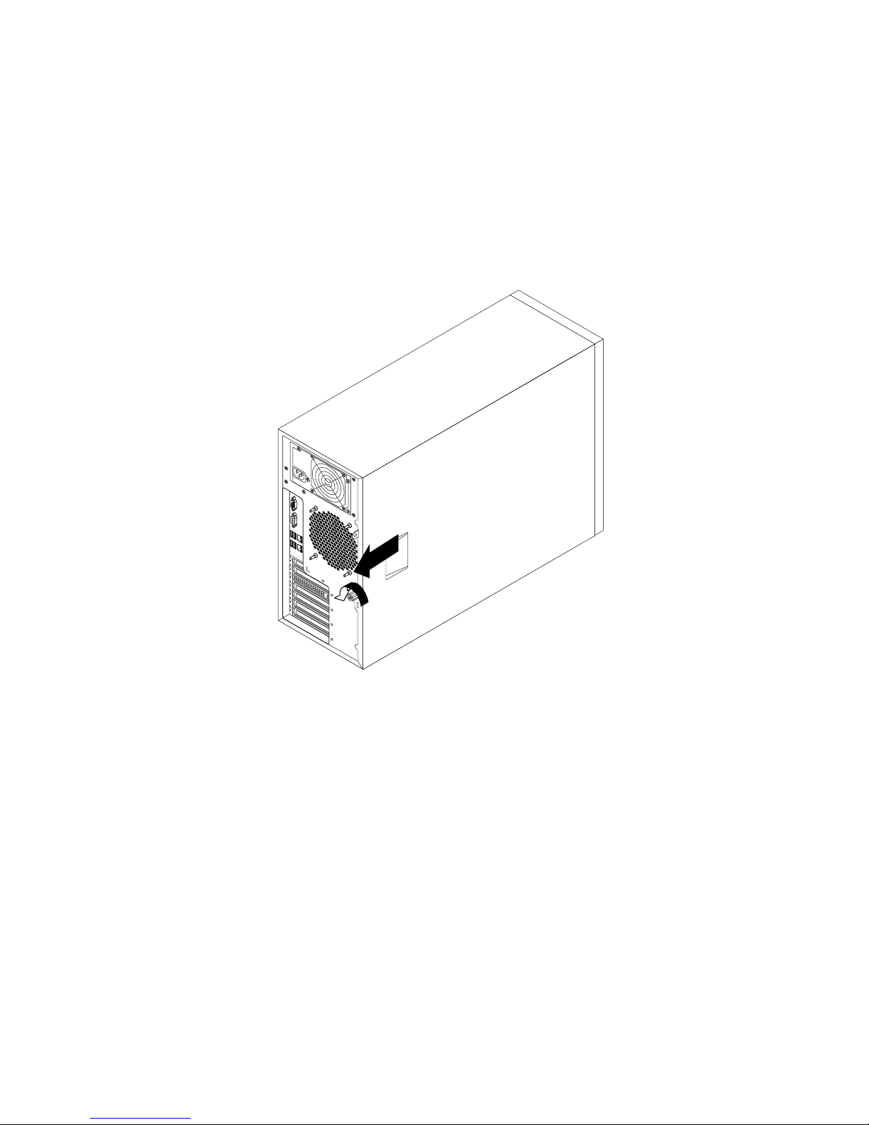
5.Loosenthethumbscrewthatsecurestheservercoverandthenslidetheservercovertotherearuntilit
isstopped.
Notes:
a.Theservercoverissecurelyinstalledandyouneedtouseatool,suchasascrewdriver,toloosen
thethumbscrewthatsecurestheservercover.Thethumbscrewisanintegratedpartoftheserver
coveranddonottrytoremovethethumbscrewfromtheservercover.
b.Itisrecommendedthatyouwaitthreetoveminutestolettheservercoolbeforeremovingthe
servercover.
Figure32.Slidingtheservercovertotherear
86ThinkServerUserGuide
Page 99
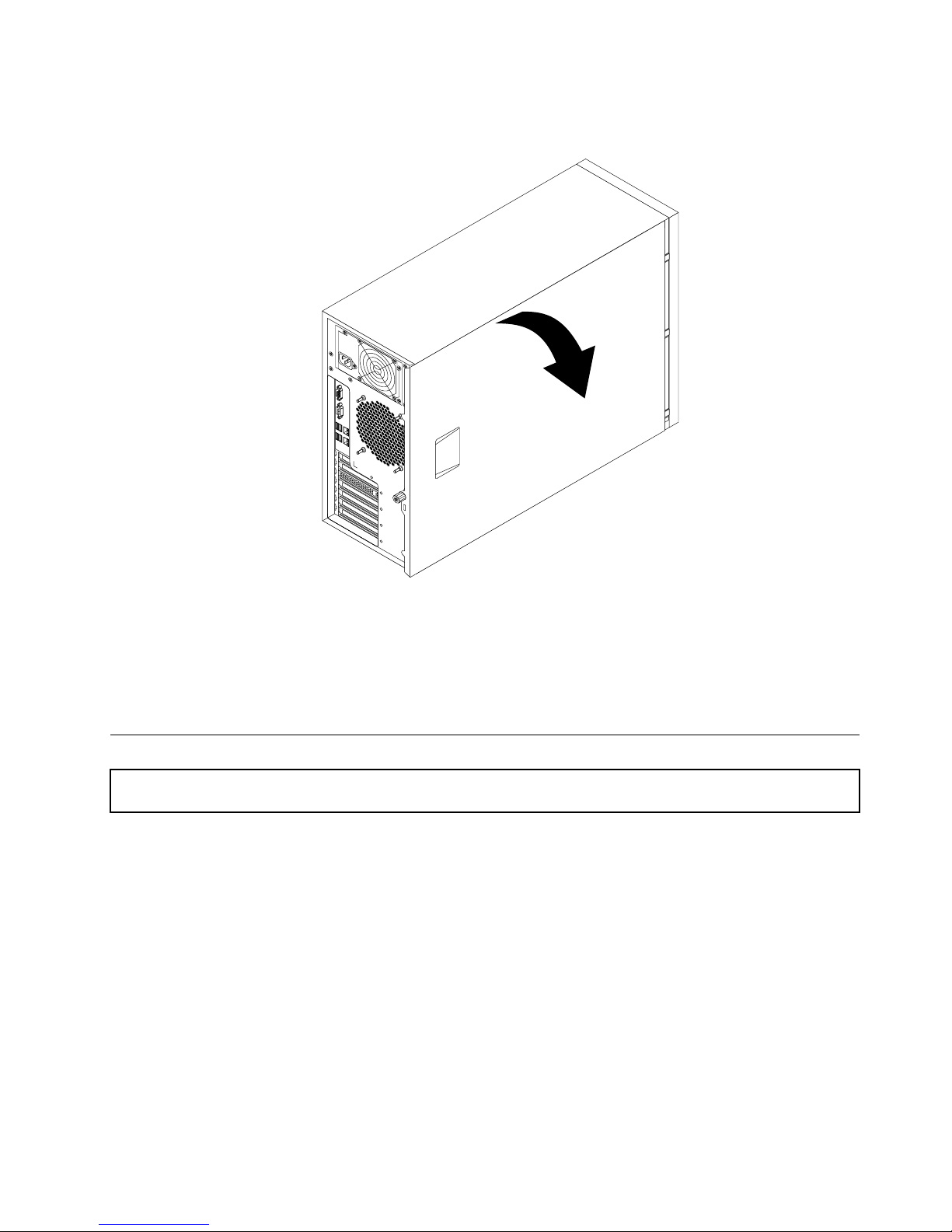
6.Pivottheservercoveroutwardtocompletelyremoveit.
Figure33.Removingtheservercover
Attention:Forpropercoolingandairow,installtheservercoverbeforeturningontheserver.Operatingthe
serverformorethan30minuteswiththeservercoverremovedmightdamageservercomponents.
Toreinstalltheservercover,see“Reinstallingtheservercoverandreconnectingcables”onpage162.
Removingandreinstallingthefrontbezel
Attention:Donotopenyourserverorattemptanyrepairbeforereadingandunderstandingthe“Safetyinformation”
onpageiiiand“Guidelines”onpage83.
Thistopicprovidesinstructionsonhowtoremoveandreinstallthefrontbezel.
Beforeyoubegin,printalltherelatedinstructionsorensurethatyoucanviewthePDFversiononanother
computerforreference.
Note:Dependingonthemodel,yourservermightlookslightlydifferentfromtheillustrationsinthistopic.
Toremoveandreinstallthefrontbezel,dothefollowing:
1.Removeallmediafromthedrivesandturnoffallattacheddevicesandtheserver.Then,disconnectall
powercordsfromelectricaloutletsanddisconnectallcablesthatareconnectedtotheserver.
2.Removetheservercover.See“Removingtheservercover”onpage85.
Chapter6.Installing,removing,orreplacinghardware87
Page 100
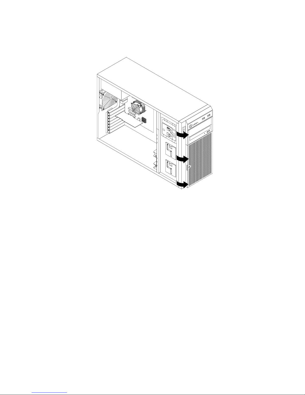
3.Removethefrontbezelbyreleasingthethreeplastictabsontheleftsideandpivotingthefrontbezel
outward.
Figure34.Removingthefrontbezel
88ThinkServerUserGuide
 Loading...