

Page 1

HardwareMaintenanceManual
ThinkPadX131eChromebook
Page 2

Note:Beforeusingthisinformationandtheproductitsupports,besuretoreadthegeneralinformation
underAppendixA“Notices”onpage61.
ThirdEdition(December2013)
©CopyrightLenovo2013.
LIMITEDANDRESTRICTEDRIGHTSNOTICE:IfdataorsoftwareisdeliveredpursuantaGeneralServicesAdministration
“GSA”contract,use,reproduction,ordisclosureissubjecttorestrictionssetforthinContractNo.GS-35F-05925.
Page 3

Contents
Aboutthismanual...........iii
Chapter1.Safetyinformation.....1
Generalsafety...............1
Electricalsafety..............1
Safetyinspectionguide...........3
Handlingdevicesthataresensitivetoelectrostatic
discharge.................3
Groundingrequirements...........4
Safetynotices...............4
Chapter2.Generalcheckout.....7
Whattodofirst..............7
Powersystemcheckout...........8
Checkingtheacpoweradapter......8
Checkingoperationalcharging......9
Checkingthebatterypack........9
Chapter3.Importantservice
information..............11
Powermanagement............11
Symptom-to-FRUindex...........11
LCD-relatedsymptoms.........12
Intermittentproblems..........12
Undeterminedproblems.........12
OverviewoftheChromebookUSBrepairshim..13
Creatingtherepairshim.........13
Settingthewrite-protectswitch......14
Usingtherepairshim..........15
Factorytestitems............16
StrategiesforreplacingFRUs.........17
StrategyforreplacingFRUsforGAV......17
FRUidentificationforGAVproducts....17
Chapter4.Statusindicators.....19
Chapter5.Specialkeys........21
Chapter6.Locations.........23
Locatingcomputercontrols,connectors,and
indicators.................23
Frontview...............23
Rearview...............24
Bottomview..............24
LocatingFRUsandCRUs..........24
MajorFRUsandCRUs..........26
LCDFRUsandCRUs..........28
Miscellaneouskitsandotherparts.....29
Chapter7.Removingorreplacinga
FRU..................31
Generalguidelines.............31
Screwnotices...............32
Hardwareidentity.............32
PrerequisiteforreplacingaFRU........33
1010Batterypack.............33
1020Bottomslotcover...........34
1030Memorymodules...........35
1040PCIExpressMiniCardforwirelessLAN..36
1050mSA T Asolid-statedrive.........37
1060PCIExpressMiniCardforwirelessWAN..38
1070Harddiskdriveorsolid-statedrive
assembly.................39
1080Harddiskdrivebracket.........40
1090Keyboard..............41
1110Keyboardbezelassembly........44
1120Microphone.............46
1130Speakerassembly...........47
1140I/Oboard..............48
1150CRTboardassembly(withcable).....49
1160Systemboardassemblyandthermalfan
assembly.................49
1170DC-incableandbasecoverassembly...52
2010LCDunit...............53
2020LCDbezelassembly..........55
2030LCDpanel,LCDcable,andhinges....56
2040Cameraandcameracable........57
2050AntennakitandLCDrearcoverassembly..58
AppendixA.Notices..........61
Electronicemissionnotices..........62
Trademarks................62
AppendixB.Abbreviationtable....63
©CopyrightLenovo2013
i
Page 4

iiHardwareMaintenanceManual
Page 5

Aboutthismanual
ThismanualcontainsserviceandreferenceinformationforthefollowingThinkPad
ThinkPadX131eChromebook
Machinetype(MT)6283
TM
®
products.
Usethismanualalongwiththeadvanceddiagnosticteststotroubleshootproblems.
Important:ThismanualisintendedonlyfortrainedservicetechnicianswhoarefamiliarwithThinkPad
products.Usethismanualalongwiththeadvanceddiagnosticteststotroubleshootproblemseffectively.
BeforeservicingaThinkPadproduct,besuretoreadalltheinformationunderandChapter3“Important
serviceinformation”onpage11.
©CopyrightLenovo2013
iii
Page 6

ivHardwareMaintenanceManual
Page 7

Chapter1.Safetyinformation
Thischapterpresentsfollowingsafetyinformationthatyouneedtobefamiliarwithbeforeyouservicea
ThinkPadnotebookcomputer.
•“Generalsafety”onpage1
•“Electricalsafety”onpage1
•“Safetyinspectionguide”onpage3
•“Handlingdevicesthataresensitivetoelectrostaticdischarge”onpage3
•“Groundingrequirements”onpage4
•“Safetynotices”onpage4
Generalsafety
Followtheserulestoensuregeneralsafety:
•Observegoodhousekeepingintheareaofthemachinesduringandaftermaintenance.
•Whenliftinganyheavyobject:
1.Ensurethatyoucanstandsafelywithoutslipping.
2.Distributetheweightoftheobjectequallybetweenyourfeet.
3.Useaslowliftingforce.Nevermovesuddenlyortwistwhenyouattempttolift.
4.Liftbystandingorbypushingupwithyourlegmuscles;thisactionremovesthestrainfromthe
musclesinyourback.Donotattempttoliftanyobjectthatweighsmorethan16kg(35lb)orthatyou
thinkistooheavyforyou.
•Donotperformanyactionthatcauseshazardstothecustomer,orthatmakestheequipmentunsafe.
•Beforeyoustartthemachine,ensurethatotherservicetechniciansandthecustomer'spersonnelare
notinahazardousposition.
•Placeremovedcoversandotherpartsinasafeplace,awayfromallpersonnel,whileyouareservicing
themachine.
•Keepyourtoolcaseawayfromwalkareassothatotherpeoplewillnottripoverit.
•Donotwearlooseclothingthatcanbetrappedinthemovingpartsofamachine.Ensurethatyoursleeves
arefastenedorrolledupaboveyourelbows.Ifyourhairislong,fastenit.
•Inserttheendsofyournecktieorscarfinsideclothingorfastenitwithanonconductiveclip,about8
centimeters(3inches)fromtheend.
•Donotwearjewelry,chains,metal-frameeyeglasses,ormetalfastenersforyourclothing,becausemetal
objectsaregoodelectricalconductors.
•Wearsafetyglasseswhenyouarehammering,drilling,soldering,cuttingwire,attachingsprings,using
solvents,orworkinginanyotherconditionsthatmightbehazardoustoyoureyes.
•Afterservice,reinstallallsafetyshields,guards,labels,andgroundwires.Replaceanysafetydevice
thatiswornordefective.
•Reinstallallcoverscorrectlybeforereturningthemachinetothecustomer.
•Fanlouversonthemachinehelptopreventoverheatingofinternalcomponents.Donotobstructfan
louversorcoverthemwithlabelsorstickers.
Electricalsafety
Observethefollowingruleswhenworkingonelectricalequipment.
©CopyrightLenovo2013
1
Page 8

Important:
•Useonlyapprovedtoolsandtestequipment.Somehandtoolshavehandlescoveredwithasoftmaterial
thatdoesnotinsulateyouwhenworkingwithliveelectricalcurrents.
•Manycustomershave,neartheirequipment,rubberfloormatsthatcontainsmallconductivefibersto
decreaseelectrostaticdischarges.Donotusethistypeofmattoprotectyourselffromelectricalshock.
•Findtheroomemergencypower-off(EPO)switch,disconnectingswitch,orelectricaloutlet.Ifanelectrical
accidentoccurs,youcanthenoperatetheswitchorunplugthepowercordquickly.
•Donotworkaloneunderhazardousconditionsornearequipmentthathashazardousvoltages.
•Disconnectallpowerbefore:
–Performingamechanicalinspection
–Workingnearpowersupplies
–Removingorinstallingmainunits
•Beforeyoustarttoworkonthemachine,unplugthepowercord.Ifyoucannotunplugit,askthecustomer
topoweroffthewallboxthatsuppliespowertothemachine,andtolockthewallboxintheoffposition.
•Ifyouneedtoworkonamachinethathasexposedelectricalcircuits,observethefollowingprecautions:
–Ensurethatanotherperson,familiarwiththepower-offcontrols,isnearyou.Thatpersonmustbe
theretoswitchoffthepower,ifnecessary.
–Useonlyonehandwhenworkingwithpowered-onelectricalequipment;keeptheotherhandinyour
pocketorbehindyourback.
CAUTION:
Anelectricalshockcanoccuronlywhenthereisacompletecircuit.Byobservingtheabove
rule,youmaypreventacurrentfrompassingthroughyourbody.
–Whenusingtesters,setthecontrolscorrectlyandusetheapprovedprobeleadsandaccessoriesfor
thattester.
–Standonsuitablerubbermats(obtainedlocally,ifnecessary)toinsulateyoufromgroundssuchas
metalfloorstripsandmachineframes.
Observethespecialsafetyprecautionswhenyouworkwithveryhighvoltages.Instructionsforthese
precautionsareinthesafetysectionsofmaintenanceinformation.Useextremecarewhenmeasuring
highvoltages.
•Regularlyinspectandmaintainyourelectricalhandtoolsforsafeoperationalcondition.
•Donotusewornorbrokentoolsandtesters.
•Neverassumethatpowerhasbeendisconnectedfromacircuit.First,checkthatithasbeenpoweredoff.
•Alwayslookcarefullyforpossiblehazardsinyourworkarea.Examplesofthesehazardsaremoistfloors,
nongroundedpowerextensioncables,powersurges,andmissingsafetygrounds.
•Donottouchliveelectricalcircuitswiththereflectivesurfaceofaplasticdentalmirror.Thesurfaceis
conductive;suchtouchingcancausepersonalinjuryandmachinedamage.
•Donotservicethefollowingpartswiththepoweron:
–Powersupplyunits
–Pumps
–Blowersandthermalfanassembly
–Motorgenerators
–Unitssimilartothoselistedabove
Thispracticeensurescorrectgroundingoftheunits.
•Ifanelectricalaccidentoccurs:
–Usecaution;donotbecomeavictimyourself.
–Switchoffpower.
–Sendanotherpersontogetmedicalaid.
2HardwareMaintenanceManual
Page 9

Safetyinspectionguide
Thepurposeofthisinspectionguideistoassistyouinidentifyingpotentiallyunsafeconditions.Aseach
machinewasdesignedandbuilt,requiredsafetyitemswereinstalledtoprotectusersandservicetechnicians
frominjury.Thisguideaddressesonlythoseitems.Y oushouldusegoodjudgmenttoidentifypotential
safetyhazardsduetoattachmentofnon- ThinkPadfeaturesoroptionsnotcoveredbythisinspectionguide.
Ifanyunsafeconditionsarepresent,youmustdeterminehowserioustheapparenthazardcouldbeand
whetheryoucancontinuewithoutfirstcorrectingtheproblem.
Considertheseconditionsandthesafetyhazardstheypresent:
•Electricalhazards,especiallyprimarypower(primaryvoltageontheframecancauseseriousorfatal
electricalshock)
•Explosivehazards,suchasadamagedCRTfaceorabulgingcapacitor
•Mechanicalhazards,suchaslooseormissinghardware
Todeterminewhetherthereareanypotentiallyunsafeconditions,usethefollowingchecklistatthebeginning
ofeveryservicetask.Beginthecheckswiththepoweroff,andthepowercorddisconnected.
Checklist:
1.Checkexteriorcoversfordamage(loose,broken,orsharpedges).
2.T urnoffthecomputer.Disconnectthepowercord.
3.Checkthepowercordfor:
a.Athird-wiregroundconnectoringoodcondition.Useametertomeasurethird-wireground
continuityfor0.1ohmorlessbetweentheexternalgroundpinandtheframeground.
b.ThepowercordshouldbetheauthorizedtypespecifiedforyourcomputerontheWebpage
http://www.lenovo.com/serviceparts-lookup.
c.Insulationmustnotbefrayedorworn.
4.Checkforcrackedorbulgingbatteries.
5.Removethecover.
6.Checkforanyobviousnon- ThinkPadalterations.Usegoodjudgmentastothesafetyofany
non-ThinkPadalterations.
7.Checkinsidetheunitforanyobviousunsafeconditions,suchasmetalfilings,contamination,wateror
otherliquids,orsignsoffireorsmokedamage.
8.Checkforworn,frayed,orpinchedcables.
9.Checkthatthepower-supplycoverfasteners(screwsorrivets)havenotbeenremovedortamperedwith.
Handlingdevicesthataresensitivetoelectrostaticdischarge
Anycomputerpartcontainingtransistorsorintegratedcircuits(ICs)shouldbeconsideredsensitiveto
electrostaticdischarge(ESD).ESDdamagecanoccurwhenthereisadifferenceinchargebetweenobjects.
ProtectagainstESDdamagebyequalizingthechargesothatthemachine,thepart,theworkmat,andthe
personhandlingthepartareallatthesamecharge.
Notes:
1.Useproduct-specificESDprocedureswhentheyexceedtherequirementsnotedhere.
2.EnsurethattheESDprotectivedevicesyouusehavebeencertified(ISO9000)asfullyeffective.
Chapter1.Safetyinformation3
Page 10
WhenhandlingESD-sensitiveparts:
•Keepthepartsinprotectivepackagesuntiltheyareinsertedintotheproduct.
•Avoidcontactwithotherpeople.
•Wearagroundedwriststrapagainstyourskintoeliminatestaticonyourbody.
•Preventthepartfromtouchingyourclothing.Mostclothingisinsulativeandretainsachargeeven
whenyouarewearingawriststrap.
•Useagroundedworkmattoprovideastatic-freeworksurface.Thematisespeciallyusefulwhen
handlingESD-sensitivedevices.
•Selectagroundingsystem,suchasthoselistedbelow,toprovideprotectionthatmeetsthespecific
servicerequirement.
Note:TheuseofagroundingsystemtoguardagainstESDdamageisdesirablebutnotnecessary.
–AttachtheESDgroundcliptoanyframeground,groundbraid,orgreen-wireground.
–Whenworkingonadouble-insulatedorbattery-operatedsystem,useanESDcommongroundor
referencepoint.Y oucanusecoaxorconnector-outsideshellsonthesesystems.
–Usetheroundgroundprongoftheacplugonac-operatedcomputers.
Groundingrequirements
Electricalgroundingofthecomputerisrequiredforoperatorsafetyandcorrectsystemfunction.Proper
groundingoftheelectricaloutletcanbeverifiedbyacertifiedelectrician.
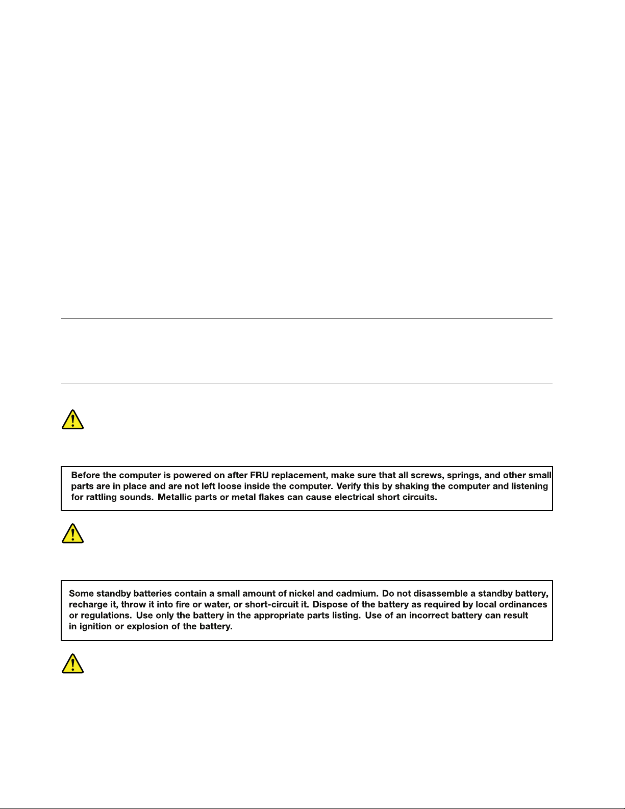
Safetynotices
DANGER
DANGER
DANGER
4HardwareMaintenanceManual
Page 11
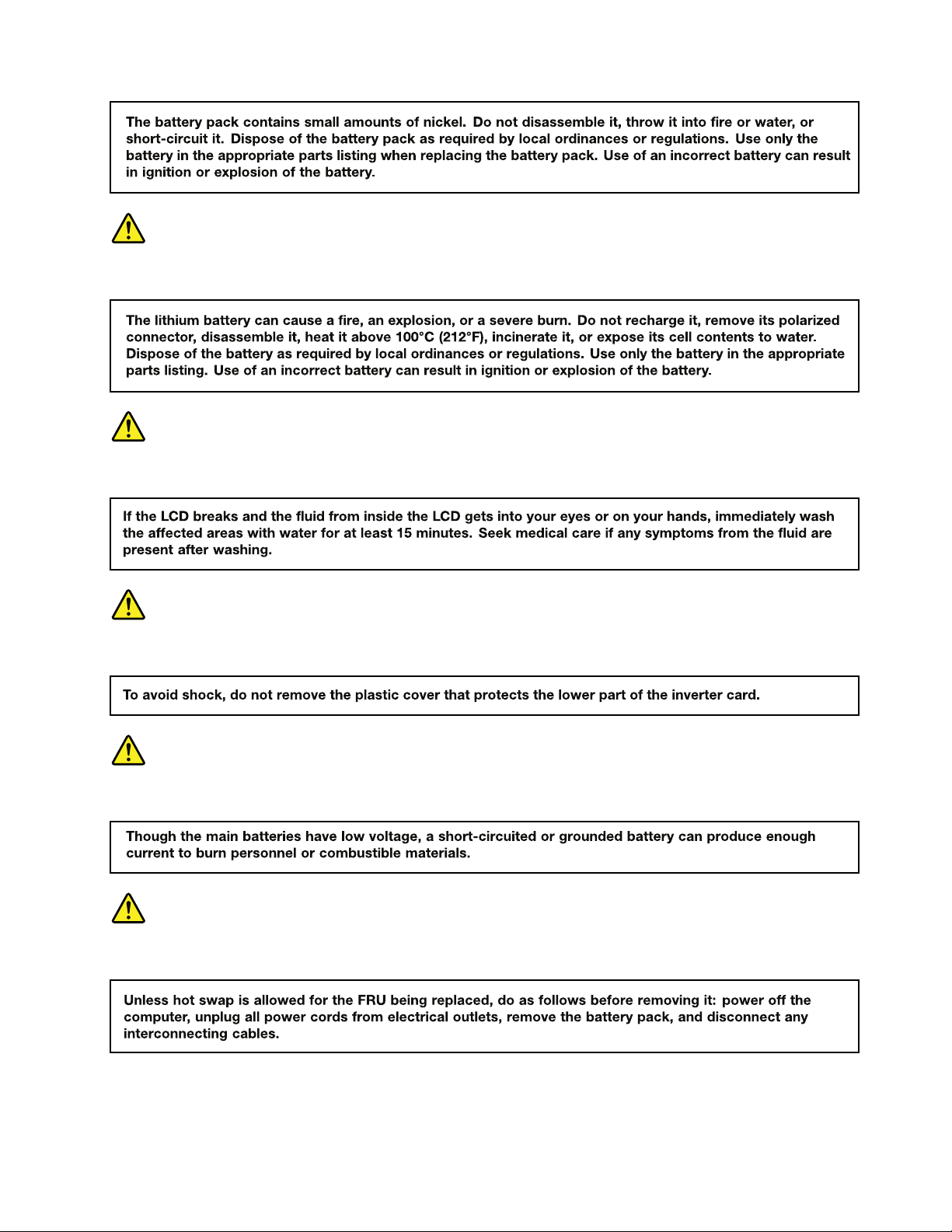
DANGER
DANGER
DANGER
DANGER
DANGER
Chapter1.Safetyinformation5
Page 12

6HardwareMaintenanceManual
Page 13

Chapter2.Generalcheckout
Thischapterpresentsfollowinginformation:
•“Whattodofirst”onpage7
•“Powersystemcheckout”onpage8
Besuretoreadthefollowingimportantnotes.
Important:
•Onlycertifiedtrainedpersonnelshouldservicethecomputer.PersonnelrepairingtheLenovo
ChromebookcomputermusthavecompletedthecertificationcoursenumberRTPW1170or
CTPi217.
•BeforereplacinganyFieldReplaceableUnit(FRU),readtheentirepageonremovingandreplacing
FRUs.
•WhenyoureplaceFRUs,itisrecommendedtousenewnylon-coatedscrews.
•Beextremelycarefulduringsuchwriteoperationsascopying,saving,orformatting.Thesequence
ofthedrivesinthecomputerthatyouareservicingmighthavebeenaltered.Ifyouselectanincorrect
drive,dataorprogramsmightbeoverwritten.
•ReplaceaFRUonlywithanotherFRUofthecorrectmodel.WhenyoureplaceaFRU,ensurethatthe
modelofthemachineandtheFRUpartnumberarecorrectbyreferringtotheFRUpartslistontheWeb
pagehttp://www.lenovo.com/serviceparts-lookup.
•AFRUshouldnotbereplacedbecauseofasingle,unreproduciblefailure.Singlefailurescanoccur
foravarietyofreasonsthathavenothingtodowithahardwaredefect,suchascosmicradiation,
electrostaticdischarge,orsoftwareerrors.ConsiderreplacingaFRUonlywhenaproblemrecurs.Ifyou
suspectthataFRUisdefective,cleartheerrorlogandrunthetestagain.Iftheerrordoesnotrecur,do
notreplacetheFRU.
•BecarefulnottoreplaceanondefectiveFRU.
Whattodofirst
WhenyoureturnaFRU,youmustincludethefollowinginformationinthepartsexchangeformorparts
returnformthatyouattachtoit:
1.Nameandphonenumberofservicetechnician
2.Dateofservice
3.Dateonwhichthemachinefailed
4.Dateofpurchase
5.Failuresymptoms,errorcodesappearingonthedisplay,andbeepsymptoms
6.ProcedureindexandpagenumberinwhichthefailingFRUwasdetected
7.FailingFRUnameandpartnumber
8.Machinetype,modelnumber,andserialnumber
9.Customer'snameandaddress
Note:Duringthewarrantyperiod,thecustomermayberesponsibleforrepaircostsifthecomputerdamage
wascausedbymisuse,accident,modification,unsuitablephysicaloroperatingenvironment,orimproper
maintenancebythecustomer.Followingisalistofsomecommonitemsthatarenotcoveredunderwarranty
andsomesymptomsthatmightindicatethatthesystemwassubjecttostressbeyondnormaluse.
Beforecheckingproblemswiththecomputer,determinewhetherthedamageiscoveredunderthewarranty
byreferringtothefollowinglist:
Thefollowingarenotcoveredunderwarranty:
©CopyrightLenovo2013
7
Page 14
•LCDpanelcrackedfromtheapplicationofexcessiveforceorfrombeingdropped
1
2
3
(20V)
•Scratched(cosmetic)parts
•Distortion,deformation,ordiscolorationofthecosmeticparts
•Plasticparts,latches,pins,orconnectorsthathavebeencrackedorbrokenbyexcessiveforce
•Damagecausedbyliquidspilledintothesystem
•DamagecausedbytheimproperinsertionofaPCCardortheinstallationofanincompatiblecard
•Fusesblownbyattachmentofanonsupporteddevice
•Forgottencomputerpassword(makingthecomputerunusable)
•Stickykeyscausedbyspillingaliquidontothekeyboard
•Useofanincorrectacpoweradapteronlaptopproducts
Thefollowingsymptommightindicatedamagecausedbynonwarrantedactivities:
•Missingpartsmightbeasymptomofunauthorizedserviceormodification.
•Checkforobviousdamagetoaharddiskdrive.Ifthespindleofaharddiskdrivebecomesnoisy,thehard
diskdrivemighthavebeendroppedorsubjecttoexcessiveforce.
Powersystemcheckout
Toverifyasymptom,dothefollowing:
1.T urnoffthecomputer.
2.Removethebatterypack.
3.Connecttheacadapter.
4.Checkthatpowerissuppliedwhenyouturnonthecomputer.
5.T urnoffthecomputer.
6.Disconnecttheacadapterandinstallthechargedbatterypack.
7.Checkthatthebatterypacksuppliespowerwhenyouturnonthecomputer.
Ifyoususpectapowerproblem,seetheappropriateoneofthefollowingpowersupplycheckouts:
•“Checkingtheacpoweradapter”onpage8
•“Checkingoperationalcharging”onpage9
•“Checkingthebatterypack”onpage9
Checkingtheacpoweradapter
Youareherebecausethecomputerfailsonlywhentheacpoweradapterisused.
•Ifthepower-onindicatordoesnotturnon,checkthepowercordoftheacpoweradapterforcorrect
continuityandinstallation.
•Ifthecomputerdoesnotchargeduringoperation,goto“Checkingoperationalcharging”onpage9
Tochecktheacadapter,dothefollowing:
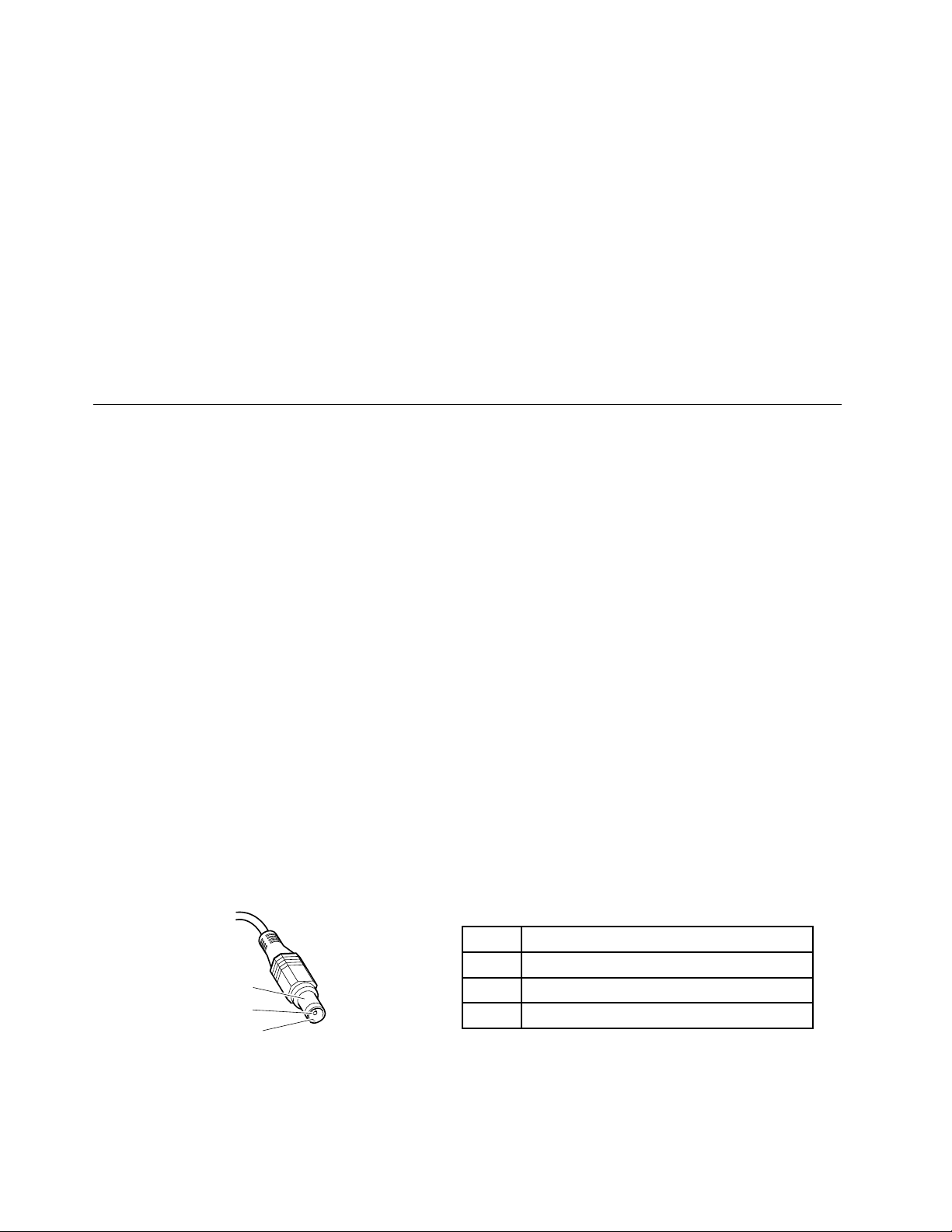
1.Unplugtheacadaptercablefromthecomputer.
2.Measuretheoutputvoltageattheplugoftheacadaptercable.Seethefollowingfigure:
Pin
1+20
20
3
Voltage(Vdc)
Ground
Note:Outputvoltageacrosspin2oftheacpoweradaptermightdifferfromtheoneyouareservicing.
3.Ifthevoltageisnotcorrect,replacetheacadapter.
4.Ifthevoltageisacceptable,replacethesystemboard.
8HardwareMaintenanceManual
Page 15

Note:Noisefromtheacadapterdoesnotalwaysindicateadefect.
1(+)
2(+)
3
4
5
6(-)
7(-)
Checkingoperationalcharging
Tocheckwhetherthebatterypackchargesproperlyduringoperation,dothefollowing:
Note:Beforeyoubegin,installadischargedbatterypackorabatterypackthathaslessthan50%ofthe
totalpowerremaininginthecomputer.
1.Ifthebatterystatusindicatororicondoesnotturnon,removethebatterypackandletitreturn
toroomtemperature.
2.Reinstallthebatterypack.
3.Ifthebatterystatusindicatorstilldoesnotturnon,replacethebatterypack.
4.Ifthebatteryindicatorstilldoesnotturnon,replacethesystemboard.Otherwise,referto“Checking
thebatterypack”onpage9
tochecktheoriginalbatterypack.
Checkingthebatterypack
Thebatterystatusindicatorislocatedinthelower-rightcornerofthescreen.T oviewthepercentageof
batterypowerremaining,clickthebatterystatusicon.
Note:Ifthebatterypackbecomeshot,itmaynotbeabletocharge.Removeitfromthecomputerandleave
itatroomtemperatureforawhile.Afteritcoolsdown,reinstallandrechargeit.
Tocheckthebatterypack,dothefollowing:
1.T urnoffthecomputeranddisconnecttheacpoweradapter.
2.Removethebatterypackandmeasurethevoltagebetweenbatteryterminals1(+)and7(-).Seethe
followingtable:
Terminal
1+0to+12.6
7
Voltage(Vdc)
Ground(-)
3.Measuretheresistancebetweenbatteryterminals5and7.Theresistanceshouldbe4to30KΩ.Ifthe
resistanceisnotcorrect,replacethebatterypack.
4.Dependingonthevoltagethatyoumeasure,dooneofthefollowing:
•Ifthevoltageislessthan+11.0Vdc,rechargethebatterypack.Ifthevoltageisstilllessthan+11.0V
dcafterrecharging,replacethebatterypack.
•Ifthevoltageismorethan+11.0Vdc,dischargethebatterypackuntilthevoltagebecomesless
than+11.0Vdc,andthenrechargethebatterypack.Ifthevoltagestillislessthan+11Vdcafter
recharging,replacethebatterypack.
Note:Rechargingwilltakeatleastthreehours,evenifthebatterystatusindicatordoesnotturnon.
5.Replacethesystemboardifthenewbatterypackisnotcharged.
Chapter2.Generalcheckout9
Page 16

10HardwareMaintenanceManual
Page 17

Chapter3.Importantserviceinformation
Thischapterpresentsthefollowingimportantservice:
•“Powermanagement”onpage11
•“Symptom-to-FRUindex”onpage11
•“OverviewoftheChromebookUSBrepairshim”onpage13
•“StrategyforreplacingFRUsforGAV”onpage17
•“StrategiesforreplacingFRUs”onpage17
Important:
•AdvisecustomerstocontacttheLenovo
TelephonenumbersforLenovoSupportareavailableat:
http://www.lenovo.com/support/phone
•SystemdisassemblyandreassemblyvideosthatshowtheFRUremovalorreplacementproceduresfor
theLenovoauthorizedservicetechniciansareavailableat:
http://www.lenovoservicetraining.com/ion/
®
CustomerSupportCenteriftheyneedanyassistance.
Powermanagement
Toreducepowerconsumption,putthecomputerintosleepmodeifyoudonotuseit.
Whenthecomputerenterssleepmode,thefollowingeventsoccur:
•TheLCDispoweredoff.
•Themicroprocessorstops.
Toentersleepmode,closethelidifyouareloggedin.Toresumefromsleepmode,openthecomputer
lidandpressanykey.
Note:Ifyouarenotloggedin,closingthelidwillshutdownthecomputer.
Incertaincircumstances,thecomputergoesintosleepmodeautomatically:
•Afteraperiodofinactivity
•Whenthebatteryindicatorblinksorange,indicatingthatthebatterypowerislow
Note:Thecomputerdoesnotacceptanyinputimmediatelyafteritenterssleepmode.Waitafewseconds
beforetakinganyactiontoreenteroperationmode.
Also,ineitherofthefollowingevents,thecomputerautomaticallyreturnsfromsleepmodeandresumes
operation:
Symptom-to-FRUindex
Thissectioncontainsfollowinginformation:
•“LCD-relatedsymptoms”onpage12
•“Intermittentproblems”onpage12
•“Undeterminedproblems”onpage12
Thesymptom-to-FRUindexinthissectionlistssomesymptomsandtheirpossiblecauses.Themostlikely
causeislistedfirst,inboldfacetype.
©CopyrightLenovo2013
11
Page 18

Note:DotheFRUreplacementorotheractionsinthesequenceshowninthecolumnheaded“FRUor
action,insequence. ”IfreplacingaFRUdoesnotsolvetheproblem,puttheoriginalpartbackinthe
computer.DonotreplaceanondefectiveFRU.
ThisindexcanalsohelpyoudeterminewhatFRUsneedtobereplacednextduringregularservicing.
LCD-relatedsymptoms
Important:TheTFTLCDforthenotebookcomputercontainsmanythin-filmtransistors(TFT s).The
presenceofasmallnumberofdotsthataremissing,discolored,oralwayslightedischaracteristicofTFT
LCDtechnology,butexcessivepixelproblemscancauseviewingconcerns.IftheLCDyouareservicinghas
twoorlessvisibledefectivepixels,itshouldnotbeconsideredfaulty.However,iftheLCDhasthreeormore
visibledefectivepixels,itwillbedeemedasdefectivebyLenovoanditshouldbereplaced.
Notes:
•ThispolicyappliestoallThinkPadnotebookcomputerspurchasedon1January,2008orlater.
•LenovowillnotprovidewarrantyreplacementiftheLCDiswithinspecificationsbecausewecannot
guaranteethatanyreplacementLCDwillhavezeropixeldefects
•OnepixelconsistsofR,G,Bsub-pixels.
Table1.LCD-relatedsymptoms
Symptomorerror
Nobeep,power-onindicatoron,andablankLCDduring
POST.
•LCDbacklightnotworking
•LCDtoodark
•LCDbrightnesscannotbeadjusted.
•LCDcontrastcannotbeadjusted.
•LCDscreenunreadable
•Charactersmissingpixels
•Screenabnormal
•Wrongcolordisplayed
HorizontalorverticallinesdisplayedonLCDLCDassembly
FRUoraction,insequence
Systemboard
1.ReseattheLCDconnectors.
2.LCDassembly
3.Systemboard
1.Seeimportantnotefor“LCD-relatedsymptoms.”
2.ReseatallLCDconnectors.
3.LCDassembly
4.Systemboard
Intermittentproblems
Intermittentsystemhangproblemscanbeduetoavarietyofcausesthathavenothingtodowithahardware
defect,suchascosmicradiation,electrostaticdischarge,orsoftwareerrors.FRUreplacementshouldbe
consideredonlywhenaproblemrecurs.
Undeterminedproblems
Ifwrongdevicesareinstalled,orifthesystemsimplyisnotoperating,followtheseprocedurestoisolatethe
failingFRU(donotisolateFRUsthathavenodefects).
Verifythatallattacheddevicesaresupportedbythecomputer.
Verifythatthepowersupplybeingusedatthetimeofthefailureisoperatingcorrectly.(See“Powersystem
checkout”onpage8
)
1.T urnoffthecomputer.
2.VisuallycheckeachFRUfordamage.ReplaceanydamagedFRU.
3.Removeordisconnectallofthefollowingdevices:
12HardwareMaintenanceManual
Page 19

a.Non- ThinkPaddevices
b.Printer,mouse,andotherexternaldevices
c.Batterypack
d.Harddiskdriveorsolid-statedrive
e.Externaldrive
f.Memorymoduleinstalledinslotb(“1030Memorymodules”onpage35)
g.PCCards
4.T urnonthecomputer.
5.Determinewhethertheproblemhasbeensolved.
6.Iftheproblemdoesnotrecur,reconnecttheremoveddevicesoneatatimeuntilyoufindthefailingFRU.
7.Iftheproblemremains,replacethefollowingFRUsoneatatime(donotreplaceanondefectiveFRU):
a.Systemboard
b.LCDassembly
OverviewoftheChromebookUSBrepairshim
ThissectionprovidesinformationabouttherecoverysolutionontheChromeOS
usingtheChromebookUSBrepairshim(hereafterreferredtoastherepairshim).
TherepairshimisabootabledevicethatisrequiredtoservicetheChromebookcomputer.Therepair
shimisusedforthefollowingpurposes:
•Diagnoseproblemsandrestorethesystemtothefactorydefaultsettings
•Refreshthesystemwiththelatestfirmwareandsoftware
TM
operatingsystemby
TherepairshimisnotnecessarywhenaCustomerReplaceableUnit(CRU)isreplaced.Ifanon-CRUis
broken,orthereisastrongsuspicionthataparticularnon-CRUisdefective,itcanbereplacedbeforeusing
therepairshim.Otherwise,therepairshimmustbeusedbeforeanynon-CRUisreplaced.
ThefollowingisthelistofCRUsforaChromebookcomputer:
•acpoweradapter
•Batterypack
•Bottomslotcover
•Keyboard
•Memorymodule
•T rackpointcap
ForCRUdefinition,see“LocatingFRUsandCRUs”onpage24
.
Creatingtherepairshim
LenovoservicetechniciansneedtodownloadtherepairshimimagefromtheLenovoSupportWebsiteto
createarepairshim.ALenovoservicecredentialisrequiredtodownloadtheimage.
Notes:
•T ocreatetherepairshim,aUSBdevicewithatleast4gigabyte(GB)ofstorageisrequired.Therequired
USBstoragecapacitydependsonthesizeoftherecoveryimage.
•Y oumightalsoneedarecoverytooltocreatetherepairshim.Topreventpotentialperformancerisksor
unexpectedfailure,itisrecommendedthatyouusetheWin32DiskImagertocreatetherepairshim.
•Ensurethatyoucreatetherepairshimusingthelatestversionoftherepairshimimage.Ifyouusean
earlierversion,itmightcausetherepairprocesstofail.
Chapter3.Importantserviceinformation13
Page 20

Tocreatetherepairshim,dothefollowing:
Attention:CreatingtherepairshimwilldeletealldatastoredontheUSBdevice.T oavoiddataloss,makea
backupcopyofallthedatathatyouwanttokeep.
1.DownloadthelatestversionoftherepairshimimagefromtheLenovoSupportWebsiteat:
http://www.lenovo.com/support
2.Extractthedownloadedfilethatcontainstherepairshimimage.
3.Downloadtherecoverytool.TheWin32DiskImagerrecoverytoolisavailableat:
http://sourceforge.net/projects/win32diskimager/
4.Runtherecoverytoolandfollowtheinstructionsonthescreentocreatetherecoveryshim.
5.AfteryourecovertheChromebookcomputer,formattheUSBdevice.IfyoudonotformattheUSB
device,youwillnotbeabletousethestoragespace.Also,theUSBdevicemightnotberecognizable
bytheWindowsoperatingsystem.
Settingthewrite-protectswitch
Bydefault,theon-boardRead-OnlyMemories(ROMs)aresetaswrite-protected.Beforerefreshingthe
Chromebookfirmware,settheROMsasunprotectedbyflippingthewrite-protectswitchonthesystem
board.
Toflipthewrite-protectswitch,dothefollowing:
1.Disconnecttheacpoweradapterandallcablesfromthecomputer,andthenremovethebatterypack.
See“1010Batterypack”onpage33.
2.Removethebottomslotcover.See“1020Bottomslotcover”onpage34.
3.Dependingonthemodeltype,dothefollowing:
•Formodelswithaharddiskdriveorsolid-statedriveinstalled,removetheharddiskdriveor
solid-statedrive.See“1070Harddiskdriveorsolid-statedriveassembly”onpage39.
•Formodelswithanemptyharddiskdrivebracketinstalled,removetheharddiskdrivebracket.
See“1080Harddiskdrivebracket”onpage40.
4.Removethekeyboard.See“1090Keyboard”onpage41.
5.Removethekeyboardbezelassembly.See“1110Keyboardbezelassembly”onpage44.
6.Locatethewrite-protectswitchonthesystemboardasshowninthefollowingillustration.T oturnoffthe
write-protectfunction,flipthewrite-protectswitchtotheleftasshownbythearrow
write-protectfunction,flipthewrite-protectswitchtotherightasshownbythearrowb.
a.T oturnonthe
14HardwareMaintenanceManual
Page 21
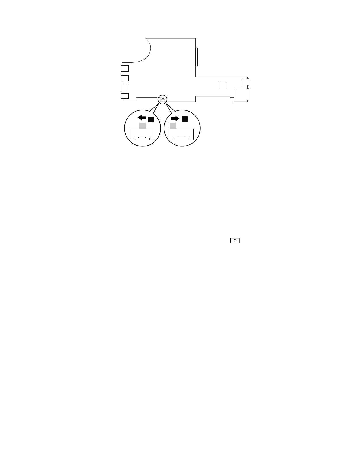
a
b
7.Afteryouhaveflippedthewrite-protectswitch,reassemblethecomputer.Reinstallthebatterybackand
reconnecttheacpoweradapterandallcables.
Usingtherepairshim
Thissectionprovidesinstructionsonhowtousetherepairshimyouhavecreated.
Tousetherepairshim,dothefollowing:
1.T urnoffthewrite-protectfunction.See“Settingthewrite-protectswitch”onpage14.
2.Disconnecttheacpoweradapter,andthenremovethebatterypack.Waitforaboutfiveseconds.Then
reinstallthebatterypack,andreattachtheacpoweradapter.
3.Waitforaboutfiveseconds.PressandholdEscandtherefreshkey(),andthenpressthepower
buttontostartthecomputerandenterrecoverymode.
4.Whentherecoveryscreenisdisplayed,pressandholdCtrl+D,andthenpressEnter.Thesystem
automaticallyrestartsandentersdevelopermode.
5.T urnoffthecomputer.Thenrepeatstep2andstep3tostartthecomputerandenterrecoverymode.
6.Whentherecoveryscreenisdisplayed,connecttherepairshimtotheUSBconnectorontheright-side
ofthecomputer.Therepairshimwillupdatethefirmwareandimageautomatically.Whentheupdate
processfinishes,thecomputerwillrestartandenterthefactory-test-imageenvironment.
Notes:
•DonotconnecttherepairshimtotheUSBconnectorsontheleft-sideofthecomputer.
•Theupdateprocessisautomatic,andtakeslessthan10minutes.Statusinformationwillbe
displayedonthecomputerscreenduringtheprocess.
7.Removetherepairshimandputitinasafeplace.Followtheinstructionsonthescreentostartthe
factorytextitems.Forinformationaboutthefactorytestitems,see“Factorytestitems”onpage16.
8.Ifthefactorytestitemsrevealedadefectivecomponent,turnoffthecomputer,disconnecttheacpower
adapter,andthenreplacethedefectivecomponent.Formoreinformationaboutthereplacement
procedure,seeChapter7“RemovingorreplacingaFRU”onpage31.
9.T urnonthewrite-protectfunction.See“Settingthewrite-protectswitch”onpage14.
10.T urnonthecomputer,anditwillenterthefactory-test-imageenvironmentagain.Itisrecommendedthat
yourunStressT estandFactoryFlowT esttoensurethatnewcomponentsfunctioncorrectly.
Chapter3.Importantserviceinformation15
Page 22

Note:Itisnotnecessarytoturnoffthewrite-protectfunctionagainifadditionalcomponentsneed
tobereplaced.
11.RuntheGoogleRequiredT est(GRT)andtheHardwareIdentity(HWID)T est.Ifthetestsfinish
successfully,thesystemwillautomaticallyrestartandentertheChromeOSoperatingsystem.
Notes:
•Ifthesystemboardisreplaced,youarerequiredtoenterthe16-charactermachinetypeandmodel
(MTM)andserialnumber(SN)string.Thestringconsistsofthe4-digitmachinetype,3-digitmodel
number,7-digitSN,andisprecededbythecharacters“1S”.Y oucanfindtheMTMandSNlabel
attachedinthebatterycompartment.ForthelocationoftheMTMandSNlabel,see“Applying
labelstothebasecover”onpage53
IftheMTMandSNarealreadydisplayed,andmatchthenumbersshownonthelabelinthebattery
compartment,pressEsctoleavethevaluesastheyare.
•Ifanytestismarkedasfailed,thefinalprocesswillnotcomplete.Thefinalprocesscanbeforced
tocompletebypressingF .Donotforcethefinalprocesstocompletewhenacomponentfails
thetest.Forcethefinalprocesstocompleteonlywhenthetesthastobebypassed,becauseit
cannotbeperformed.
•Aftertherepairprocessfinishes,thesystemisinacleanout-of-boxstate.Ifapplicable,customers
needtoreenrollthesystemforenterpriseenrollment.
•IftheGRTtestfails,refertothecommonmistakesthatleadtoGRTfailurein“Factorytestitems”
onpage16
.
.
Factorytestitems
Afterthesystementersthefactory-test-imageenvironment,factorytestitemswillrun.Thefactorytest
processcontainsthefollowingthreetypesoftests:
•StressT est:TheStressT estisdesignedtotesthowthesystemfunctionsunderstressbyrunning
themaximumworkloadapplications.TheStressT estincludesthetestofthememorymodule,
microprocessor,andgraphicscard.Thetesttakesabout15minutestofinishandcanbecancelledduring
theprocess.Ifthetestiscancelled,itwillbemarkedasfailed.
•FactoryFlowTest:TheFactoryFlowTestisdesignedtotesttheindividualcomponenttoverifyits
function,suchastheTPM,display,audio,camera,keyboard,andsoon.Itisrecommendedtorunall
theFactoryFlowTestitems.SometestitemsmightrequireanHDMImonitororaSDcard.IftheHDMI
monitororSDcardisnotavailable,thetestscanbebypassed,butwiththeoveralltestmarkedasfailed.
•GRT:GRTtestchecksthesystemstatusandhelpsresetthesystembacktothefactorydefaultsettings.
Ifanythingiswrong,thetestcannotbefinalized.Thefollowingitemsaresomecommonmistakesthat
leadtoGRTtestfailure:
–HWIDmismatch:EachChromebookcomputerhasaknownhardwareconfiguration.Each
configurationisassignedaHWID.HWIDmismatchcanbecausedbyusingunauthorizedparts,or
missingparts.FormoreinformationaboutHWID,see“Hardwareidentity”onpage32
Ifthewrite-protectfunctionisnotturnedoffbeforeusingtherepairshim,itwillalsocauseHWID
mismatch.Forinstructionsonhowtoturnoffthewrite-protectfunction,see“Settingthewrite-protect
switch”onpage14
–VPD(VitalProductData)incorrect:Confirmthatthe16-characterMTMandserialnumberstring
isenteredcorrectly.Forexample,iftheMTMis6283-ABC,andtheserialnumberisLR12345,the
correctstringshouldbe“1S6283ABCLR12345”.
–Write-protectswitchisoff:Systemcannotbefinalizeduntilthewrite-protectswitchisturnedbackon.
.
.
16HardwareMaintenanceManual
Page 23

StrategiesforreplacingFRUs
UsethefollowingstrategiestopreventunnecessaryexpenseforreplacingandservicingFRUs:
•IfyouareinstructedtoreplaceaFRUbutthereplacementdoesnotcorrecttheproblem,reinstallthe
originalFRUbeforeyoucontinue.
•Somecomputershavebothaprocessorboardandasystemboard.Ifyouareinstructedtoreplaceeither
theprocessorboardorthesystemboard,andreplacingoneofthemdoesnotcorrecttheproblem,
reinstallthatboard,andthenreplacetheotherone.
•IfanadapteroradeviceconsistsofmorethanoneFRU,anyoftheFRUsmightbethecauseoftheerror.
Beforereplacingtheadapterordevice,removetheFRUs,onebyone,toseeifthesymptomschange.
ReplaceonlytheFRUthatchangedthesymptoms.
StrategyforreplacingFRUsforGAV
GeneralAnnounceVariant(GAV)
Thisisastandardmodel(fixedconfiguration).GAVsareannouncedandofferedtoallcustomers.TheMTM
portionofthemachinelabelisa4-digitMTand3-digitmodel,wheremodel=a“fixedpartnumber”,for
example:1829-F1U.Also,eSupportwilllisttheseproductsunderthesamefixedmodelnumber.
FRUidentificationforGAVproducts
UseLenovoeSupporttoidentifymajorFRUs,FRUpartnumbers,andFRUdescriptionsforGAVproducts
atanMT-serialnumberlevel.ExamplesofmajorFRUsareharddiskdrive,systemboard,liquidcrystal
display(LCD),andmemorymodule.
ToidentifythemajorFRUsforaproduct,dothefollowing:
1.Goto:
http://www.lenovo.com/support
2.ClickWarranty&Services.
3.ClickCheckWarrantyStatus.
4.OntheWarrantyStatusLookuppage,clickPartsLookup.
5.T ypeyourmachinetypeandserialnumber,andthenclickSubmit.
eSupportalsocanbeusedtoviewthegeneralFRUlistforaproduct.
TogetthegeneralFRUlistforaproduct,dothefollowing:
1.Goto:
http://www.lenovo.com/support
2.ClickParts&Accessories.
3.Followtheinstructionsonthescreentoselectproduct.
4.ClickProductsandPartsDetail.
5.OnthePRODUCTANDPARTSDETAILpage,clickthePartsDetailtabtoviewtheFRUlist.
Note:TheFRUlistisagenerallistofcomponentsanddoesnotcontainspecificmodelinformation.
Chapter3.Importantserviceinformation17
Page 24

18HardwareMaintenanceManual
Page 25

Chapter4.Statusindicators
1
2
3
4
Thischapterpresentsthesystemstatusindicatorsthatshowthestatusofthecomputer.
Table2.Statusindicators
IndicatorMeaning
1
23
4
©CopyrightLenovo2013
acpowerstatus
indicator
Systemstatus
indicator
Wirelessstatus
indicator
•Green:Theacpoweradapterisconnected.
•Off:Theacpoweradapterisnotconnected.
TheilluminateddotintheThinkPadlogoontheouterlidofthecomputerandonthe
palmrestworksasasystemstatusindicator:itshowswhetherthecomputerisin
sleep,ornormalmode.
•Red:Thecomputerison.
•Fastblinkingred:Thecomputerisenteringsleepmode.
•Slowblinkingred:Thecomputerisinsleepmode.
•Off:Thecomputerisoff.
•Green:Thewirelessfeatures,suchaswirelessLAN,Bluetooth,andwirelessWAN,
areenabled.
•Off:Thewirelessfeaturesaredisabled.
19
Page 26

20HardwareMaintenanceManual
Page 27

Chapter5.Specialkeys
Thefollowingtabledescribesthefunctionsofsomespecialkeystohelpyouusethekeyboardmore
effectively.
Specialkeys
Function
Goesbacktothepreviouspage.
Goesforwardtothenextpage.
Refreshesthecurrentpage.
Opensthecurrentpageinfull-screenmode.
Switchestothenextwindow.
Adjuststhescreenbrightnesstoalowerlevel.
Adjuststhescreenbrightnesstoahigherlevel.
Mutesthespeaker.
Decreasesthevolume.
Increasesthevolume.
Locksthecomputer.
SearchesapplicationsandtheWeb.
YoualsocanusetheSearchkeytoenableCapsLockfunctionbycustomizing
it.AfteryouhaveenabledtheCapsLockfunction,youcantypeallalphabetic
characters(A-Z)inuppercase.
TocustomizetheSearchkey,clickthestatusareainthelower-rightcornerofthe
screen,thengotoSettings➙Device➙Keyboardsettings.CustomizetheSearch
keyasdesired.
Bydefault,thiskeyissettoprovidethefunctionofaCtrlkey.However,youcan
customizeitasdesired.
Tocustomizethiskey,clickthestatusareainthelower-rightcornerofthescreen,
andthengotoSettings➙Device➙Keyboardsettings.
Openshelpinformationforthekeyboard.
©CopyrightLenovo2013
21
Page 28

22HardwareMaintenanceManual
Page 29

Chapter6.Locations
1
8
9
10
11
13
12
2
3
4
5
6
7
Thischapterintroducesthelocationsofthecomputerhardwarecomponents.
Locatingcomputercontrols,connectors,andindicators
Thistopicintroducesthelocationsofthecomputercontrols,connectors,andindicators.
Frontview
1Camera
2Securitykeyhole
3acpowerconnector
4USB2.0connector
5HDMIconnector12Microphone
6Mediacardreaderslot13Powerbutton
7Systemstatusindicator
7:Formoreinformation,seeChapter4“Statusindicators”onpage19.
©CopyrightLenovo2013
8T ouchpad
9T rackPointbuttons
10T rackPointpointingstick
11UltraNav
®
pointingdevice
23
Page 30

Rearview
1
2
7
6
5
4
3
1Systemstatusindicator5USB3.0connectors
2Wirelessstatusindicator6Fanlouver
3Comboaudioconnector7Videographicsarray(VGA)connector
4RJ45Ethernetconnector
12:Formoreinformation,seeChapter4“Statusindicators”onpage19.
Bottomview
1Batterypack3Bottomslotcover
2Batterypacklatches
LocatingFRUsandCRUs
4Speaker
Thistopicintroducesthefollowingserviceparts:
•“MajorFRUsandCRUs”onpage26
•“LCDFRUsandCRUs”onpage28
Notes:
•EachFRUisavailableforalltypesormodels,unlessotherwisespecified.
24HardwareMaintenanceManual
Page 31

•CRUstatementforcustomers:
Youcanresolvesomeproblemswithyourproductwithareplacementpartyoucaninstallyourself,
calleda“CustomerReplaceableUnit”or“CRU.”SomeCRUsaredesignatedasself-serviceCRUsand
othersaredesignatedasoptional-serviceCRUs.Installationofself-serviceCRUsisyourresponsibility.
Foroptional-serviceCRUs,youcaneitherinstalltheCRUyourselforyoucanrequestthataService
ProviderinstallstheCRUaccordingtothewarrantyserviceforyourproduct.Ifyouintendoninstalling
theCRU,LenovowillshiptheCRUtoyou.CRUinformationandreplacementinstructionsareshipped
withyourproductandareavailablefromLenovoatanytimeuponrequest.Y oucanfindalistofCRUs
foryourproductinthisHardwareMaintenanceManual.Anelectronicversionofthismanualcanbe
foundathttp://www.lenovo.com/support.ClickUserGuides&Manualsandthenfollowtheon-screen
instructionstofindthemanualforyourproduct.Y oumightberequiredtoreturnthedefectivepart
thatisreplacedbytheCRU.Whenreturnisrequired:(1)returninstructions,aprepaidshippinglabel,
andacontainerwillbeincludedwiththereplacementCRU;and(2)youmightbechargedforthe
replacementCRUifLenovodoesnotreceivethedefectiveCRUwithinthirty(30)daysofyourreceiptof
thereplacementCRU.SeeyourLenovoLimitedWarrantydocumentationforfulldetails.
ThinkPadcomputerscontainthefollowingtypesofCRUs:
–Self-serviceCRUs:TheseCRUsunplugorareheldbynomorethantwoscrews.Examplesofthese
typesofCRUsincludetheacpoweradapter,powercord,andbattery.Otherself-serviceCRUs
dependingonproductdesignmightincludethememorymodule,wirelesscard,keyboard,andpalm
restwithfingerprintreaderandtouchpad.
–Optional-serviceCRUs:TheseCRUsareisolatedpartswithinthecomputerthatareconcealedbyan
accesspanelthatistypicallysecuredbymorethantwoscrews.Oncetheaccesspanelisremoved,
thespecificCRUisvisible.
Chapter6.Locations25
Page 32

1
2
3
4
5
6
7
9
8
20
19
18
15
17
14
12
11
10
13
16
MajorFRUsandCRUs
Table3.MajorFRUsandCRUs
No.FRUdescription
1
2
LCDunit(See“LCDFRUsandCRUs”onpage28.)
KeyboardbezelassemblyNoNo
Self-serviceCRUOptional-service
CRU
NoNo
26HardwareMaintenanceManual
Page 33

Table3.MajorFRUsandCRUs(continued)
No.FRUdescription
3
4
5
6
7
8
9
10
11
12
13
14
15
16
17
18
19
20
I/Oboard
BatteryYesNo
BasecoverassemblyNoNo
DC-incableassembly
Harddiskdriveorsolidstatedrive(onsomemodels)
Harddiskdrivebracket(onsomemodels)
BottomslotcoverYesNo
PCIExpressMiniCardforwirelessLAN
PCIExpressMiniCardforwirelessWAN(onsomemodels)
mSATAsolid-statedrive(onsomemodels)
MemorymoduleYesNo
Speakerassembly
CRTboardassembly
Systemboard
Thermalfanassembly
MicrophoneNoNo
KeyboardYesNo
TrackPointcapYesNo
Self-serviceCRUOptional-service
CRU
NoNo
NoNo
NoNo
NoNo
NoNo
NoNo
NoNo
NoNo
NoNo
NoNo
NoNo
Chapter6.Locations27
Page 34

LCDFRUsandCRUs
Table4.LCDFRUsandCRUs
No.FRUdescription
Self-serviceCRUOptional-service
CRU
1
2
3
4
5
6
LCDscrewcaps
LCDbezelassembly
Camera
AntennakitNoNo
HingesNoNo
LCDrearcoverassembly
NoNo
NoNo
NoNo
NoNo
28HardwareMaintenanceManual
Page 35

Table4.LCDFRUsandCRUs(continued)
No.FRUdescription
7
8
9
Cameracable
LCDcable
LCDpanel
Miscellaneouskitsandotherparts
Table5.Miscellaneouskits
Self-serviceCRUOptional-service
CRU
NoNo
NoNo
NoNo
FRUdescriptions
LCDcovermiscellaneouskit
•LCDbracket
•LCDgasket
•LCDcoverfoil
•LCDfoilsheet
•ScrewM2xL5
•ScrewM1.7xL3
•CCDlensmylar
•Magnet
•Bezelrubber
•Antennarubber
Basecoverassemblymiscellaneouskit
•Basegasket
•Basefoil
•Batterylatch-Right
•Batterylatch-Left
•Batterylatchspring
•Batteryknob
•ScrewM2.5xL6
•ScrewM2.0xL3
•ScrewM2.0xL5
•ScrewM2.0xL8
Bottomslotcovermiscellaneouskit
•Bottomslotcoversponge
•Bottomslotcovergasket
•Bottomslotcoveracidtap
•Footrubber-leftandright
•CapturescrewM2xL4
•Mylarsheet
•Thermalmesh
Bracketextenderhalfminicard
Screwkit
Self-serviceCRUOptionalservice
NoNo
NoNo
NoNo
NoNo
NoNo
Chapter6.Locations29
Page 36

Table6.Otherparts
Descriptions
acpoweradapterYesNo
PowercordYesNo
Self-serviceCRUOptionalservice
30HardwareMaintenanceManual
Page 37

Chapter7.RemovingorreplacingaFRU
ThischapterprovidesinstructionsonhowtoremoveorreplaceaFRU.
CRUstatementforcustomers:
Youcanresolvesomeproblemswithyourproductwithareplacementpartyoucaninstallyourself,called
a“CustomerReplaceableUnit”or“CRU.”SomeCRUsaredesignatedasself-serviceCRUsandothers
aredesignatedasoptional-serviceCRUs.Installationofself-serviceCRUsisyourresponsibility.For
optional-serviceCRUs,youcaneitherinstalltheCRUyourselforyoucanrequestthataServiceProvider
installstheCRUaccordingtothewarrantyserviceforyourproduct.IfyouintendoninstallingtheCRU,
LenovowillshiptheCRUtoyou.CRUinformationandreplacementinstructionsareshippedwithyour
productandareavailablefromLenovoatanytimeuponrequest.Y oucanfindalistofCRUsforyour
productinthisHardwareMaintenanceManual.Anelectronicversionofthismanualcanbefoundat
http://www.lenovo.com/support.ClickUserGuides&Manualsandthenfollowtheon-screeninstructions
tofindthemanualforyourproduct.Y oumightberequiredtoreturnthedefectivepartthatisreplacedby
theCRU.Whenreturnisrequired:(1)returninstructions,aprepaidshippinglabel,andacontainerwillbe
includedwiththereplacementCRU;and(2)youmightbechargedforthereplacementCRUifLenovodoes
notreceivethedefectiveCRUwithinthirty(30)daysofyourreceiptofthereplacementCRU.Seeyour
LenovoLimitedWarrantydocumentationforfulldetails.
Generalguidelines
WhenremovingorreplacingaFRU,besuretoobservethefollowinggeneralguidelines:
1.Donottrytoserviceanycomputerunlessyouhavebeentrainedandcertified.Anuntrainedpersonruns
theriskofdamagingparts.
2.BeginbyremovinganyFRUsthathavetoberemovedbeforereplacingthefailingFRU.Anysuch
FRUsarelistedatthebeginningofeachFRUreplacementprocedure.Removethemintheorderin
whichtheyarelisted.
3.FollowthecorrectsequenceinthestepsforremovingtheFRU,asgiveninthedrawingsbythe
numbersinsquarecallouts.
4.Whenturningascrew,turnitinthedirectionasgivenbythearrowinthedrawing.
5.WhenremovingtheFRU,moveitinthedirectionasgivenbythearrowinthedrawing.
6.T oputthenewFRUinplace,reversetheremovalprocedureandfollowanynotesthatpertainto
replacement.
7.WhenreplacingaFRU,usethecorrectscrew(s)asshowninthereplacementprocedure.
DANGER
BeforeremovinganyFRU,turnoffthecomputer ,unplugallpowercordsfromelectricaloutlets,
removethebatterypack,andthendisconnectanyinterconnectingcables.
Attention:
•AfterreplacingaFRU,donotturnonthecomputeruntilyouhavemadesurethatallscrews,springs,and
othersmallpartsareinplaceandnonearelooseinsidethecomputer.Verifythisbyshakingthecomputer
gentlyandlisteningforrattlingsounds.Metallicpartsormetalflakescancauseelectricalshortcircuits.
•Thesystemboardissensitiveto,andcanbedamagedby,electrostaticdischarge.Beforetouchingit,
establishpersonalgroundingbytouchingagroundpointwithonehandorbyusinganelectrostatic
discharge(ESD)strap.
©CopyrightLenovo2013
31
Page 38

Screwnotices
Loosescrewscancauseareliabilityproblem.IntheThinkPadnotebookcomputer,thisproblemisaddressed
withspecialnylon-coatedscrewsthathavethefollowingcharacteristics:
•Theymaintaintightconnections.
•Theydonoteasilycomeloose,evenwithshockorvibration.
•Theyarehardertotighten.
Dothefollowingwhenyouservicethismachine:
•Keepthescrewkitinyourtoolbag.Forthepartnumberofthescrewkit,goto
http://www.lenovo.com/serviceparts-lookup.
•Itisrecommendedtousenewscrews.
•Itisrecommendedtouseeachscrewonlyonce.
•Useatorquescrewdriverifyouhaveone.
Tightenscrewsasfollows:
•Plastictoplastic
Turnanadditional90degreesafterthescrewheadtouchesthesurfaceoftheplasticpart:
•Logiccardtoplastic
Turnanadditional180degreesafterthescrewheadtouchesthesurfaceofthelogiccard:
•T orquedriver
Ifyouhaveatorquedriver,refertotheT orquecolumninthescrewinformationtableforeachstep.
–Ensurethatyouusethecorrectscrew.Itisrecommendedtousenewscrewsforreplacements.
–Ifyouhaveatorquescrewdriver,tightenallscrewsfirmlytothetorquespecifiedinthescrew
informationtableforeachstep.
–Ensurethattorquescrewdriversarecalibratedcorrectlyfollowingcountryspecifications.
Hardwareidentity
Asetofvalidhardwareidentities(HWIDs)areprovidedbyGoogle.Googlelogstheexacthardware
combinationintoaChromebookcomputerandcreatesaHWID.TheHWIDisusedtoensurethatallparts
arevalidduringtherepairoftheChromebookcomputer.TheHWIDisusedforthefollowingpurposes:
•Auto-updatenewpatchesandsoftwareforthelifetimeofthecomputer
•Recoverthecomputertothefactorydefaultsettings
32HardwareMaintenanceManual
Page 39

Ifunauthorizedpartsareinstalled,youmightnotgetthecorrectauto-updatesforyourcomputer,oryou
mightnotrecoveryourcomputersuccessfullytothefactorydefaultsettings.Forexample,ifyouinstalla
differentmodelofthewirelessLANcard,whichisnottherequiredconfiguration,theHWIDwillnotmatch.
HWIDischeckedbyusingtherepairshim.Forinformationabouttherepairshim,see“Overviewofthe
ChromebookUSBrepairshim”onpage13
.
PrerequisiteforreplacingaFRU
Usetherepairshimbeforereplacinganynon-CRUs.ThefollowingisthelistofCRUsforaChromebook
computer:
•acpoweradapter
•Batterypack
•Bottomslotcover
•Keyboard
•Memorymodule
•T rackpointcap
ForCRUdefinition,see“LocatingFRUsandCRUs”onpage24
Forinformationabouthowtousetherepairshim,see“OverviewoftheChromebookUSBrepairshim”
onpage13.
.
1010Batterypack
Note:Y oucanreplacethebatterypackonlyifitisphysicallydamagedoracustomerisreportinga
possiblesafetyissue.
Removalstepsofbatterypack
DANGER
Useonlytheauthorizedbatteryspecifiedforyourcomputer.Anyotherbatterycouldigniteor
explode.
Chapter7.RemovingorreplacingaFRU33
Page 40

1
2
2
Wheninstalling:Ensurethatthebatterylatch2isinthelockedposition.
1
1020Bottomslotcover
Foraccess,removethisFRU:
•“1010Batterypack”onpage33
Removalstepsofbottomslotcover
Note:Loosenthescrews1,butdonotremovethem.
34HardwareMaintenanceManual
Page 41

1030Memorymodules
1
1
2
a
b
Foraccess,removetheseFRUsinorder:
•“1010Batterypack”onpage33
•“1020Bottomslotcover”onpage34
Removalstepsofmemorymodules
Wheninstalling:
Note:Ifonlyonememorymoduleistobeinstalledonthecomputeryouareservicing,installeditinSLOT
a,notinSLOTb.
Insertthenotchedendofthememorymoduleintotheslot.Pressthememorymodulefirmly,andpivotit
untilitsnapsintoplace.Ensurethatitisfirmlyinstalledintheslotanddoesnotmoveeasily.
Chapter7.RemovingorreplacingaFRU35
Page 42

1040PCIExpressMiniCardforwirelessLAN
1
1
2
3
Foraccess,removetheseFRUsinorder:
•“1010Batterypack”onpage33
•“1020Bottomslotcover”onpage34
RemovalstepsofPCIExpressMiniCardforwirelessLAN
Instep1,unplugtheconnectorsbyusingtheremovaltoolantennaRFconnector.Iftheremovaltoolisnot
available,picktheconnectorswithyourfingersandgentlyunplugthem.
StepScrew(quantity)Color
2
36HardwareMaintenanceManual
M2×3mm,wafer-head,nylon-coated(1)
Torque
Black0.181Nm
(1.85kgf-cm)
Page 43

Wheninstalling:Plugtheblackcableintothemainconnector,andthegraycableintotheauxiliary
1
connector.
1050mSAT Asolid-statedrive
Foraccess,removetheseFRUsinorder:
•“1010Batterypack”onpage33
•“1020Bottomslotcover”onpage34
RemovalstepsofmSATAsolid-statedrive
ThecomputercomeswitheitheraPCIExpressMiniCardforwirelessWANoranmSATAsolid-statedrive.If
thecomputerisequippedwithanmSATAsolid-statedrive,itisinstalledinthewirelessWANcardslot.
Attention:
•Donotdropthedriveorapplyanyphysicalshocktoit.Thedriveissensitivetophysicalshock.Improper
handlingcancausedamageandpermanentlossofdata.
•Beforeremovingthedrive,havetheusermakeabackupcopyofalltheinformationonitifpossible.
•Neverremovethedrivewhilethesystemisoperatingorisinsuspendmode.
•IfthemSATAsolid-statedriveisreplaced,arecoveryimageisrequired.Instructionsonrecoveringa
ChromeOSoperatingsystemareavailableathttp://support.google.com/chromeos.
StepScrew(quantity)Color
1
M2×3mm,wafer-head,nylon-coated(1)
Torque
Black0.181Nm
(1.85kgf-cm)
Chapter7.RemovingorreplacingaFRU37
Page 44

2
1060PCIExpressMiniCardforwirelessWAN
2
1
Foraccess,removetheseFRUsinorder:
•“1010Batterypack”onpage33
•“1020Bottomslotcover”onpage34
RemovalstepsofPCIExpressMiniCardforwirelessWAN
Instep1,unplugtheconnectorsbyusingtheremovaltoolantennaRFconnectororpicktheconnectors
withyourfingersandgentlyunplugtheminthedirectionofthearrows.
StepScrew(quantity)Color
2
M2×3mm,wafer-head,nylon-coated(1)
38HardwareMaintenanceManual
Torque
Black0.181Nm
(1.85kgf-cm)
Page 45

3
Wheninstalling:Plugtheredcableintothemainconnector,andthebluecableintotheauxiliaryconnector.
1
1
2
1070Harddiskdriveorsolid-statedriveassembly
Foraccess,removetheseFRUsinorder:
•“1010Batterypack”onpage33
•“1020Bottomslotcover”onpage34
Attention:
•Donotdropthedriveorapplyanyphysicalshocktoit.Thedriveissensitivetophysicalshock.Improper
handlingcancausedamageandpermanentlossofdata.
•Beforeremovingthedrive,havetheusermakeabackupcopyofalltheinformationonitifpossible.
•Neverremovethedrivewhilethecomputerisoperatingorinsuspendmode.
Removalstepsofharddiskdriveorsolid-statedrive
StepScrew(quantity)Color
1
M2×5mm,wafer-head,nylon-coated(2)
Black0.181Nm
Chapter7.RemovingorreplacingaFRU39
Torque
(1.85kgf-cm)
Page 46

3
Wheninstalling:Ensurethattheharddiskdriveorsolid-statedriveassemblyisattachedfirmly.
1
1
2
Removalstepsoftheharddiskdriveorsolid-statedrivebracket
StepScrew(quantity)Color
1
M3×3.5mm,wafer-head,nylon-coated(2)Silver
Torque
0.392Nm
(4kgf-cm)
1080Harddiskdrivebracket
Foraccess,removetheseFRUsinorder:
•“1010Batterypack”onpage33
•“1020Bottomslotcover”onpage34
Dependingonthemodeltype,yourcomputermightnothavetheharddiskdriveorsolid-statedrive.Instead,
itwillhaveanemptyharddiskdrivebracketinstalled.
40HardwareMaintenanceManual
Page 47

Removalstepsofharddiskdrivebracket
1
1
2
1
1
StepScrew(quantity)Color
1
M2×5mm,wafer-head,nylon-coated(2)
Wheninstalling:Ensurethattheharddiskdrivebracketisattachedfirmly.
1090Keyboard
Foraccess,removetheseFRUsinorder:
•“1010Batterypack”onpage33
•“1020Bottomslotcover”onpage34
Removalstepsofkeyboard
Torque
Black0.181Nm
(1.85kgf-cm)
Wheninstalling:Ensurethatthescrewshavebeenfastenedtosecurethekeyboard.
Chapter7.RemovingorreplacingaFRU41
Page 48

StepScrew(quantity)Color
2
2
3
4
4
4
4
1
M2×8mm,wafer-head,nylon-coated(2)
Torque
Black0.181Nm
(1.85kgf-cm)
42HardwareMaintenanceManual
Page 49

5
7
6
8
9
Installationstepsofkeyboard
Toinstallthekeyboard,dothefollowing:
1.Attachtheconnectors.
2.Attachthekeyboardandensurethatthehooksonthefrontedgeofthekeyboardareundertheframe.
3.Whenthefrontedgeofthekeyboardishousedfirmly,gentlypressthekeyswithyourfingersandslide
thekeyboardtowardyouuntilthekeyboardisinplace.
Chapter7.RemovingorreplacingaFRU43
Page 50

4.Securethekeyboardbytighteningthescrewsfromthebottomsideofthecomputer.
1
1
2
2
1110Keyboardbezelassembly
Foraccess,removetheseFRUsinorder:
Note:Dependingonyourmodeltype,yourcomputermightnothavealltheFRUsthatarelisted.
•“1010Batterypack”onpage33
•“1020Bottomslotcover”onpage34
•“1070Harddiskdriveorsolid-statedriveassembly”onpage39
•“1080Harddiskdrivebracket”onpage40
•“1090Keyboard”onpage41
Removalstepsofkeyboardbezelassembly
44HardwareMaintenanceManual
Page 51

StepScrew(quantity)Color
3
3
3
6
4
5
1
2
M2.5×8mm,wafer-head,nylon-coated(2)
M2×8mm,wafer-head,nylon-coated(2)
Torque
Black0.392Nm
(4kgf-cm)
Black0.181Nm
(1.85kgf-cm)
Wheninstalling:Ensurethattheconnectorsareattachedfirmly.
StepScrew(quantity)Color
3
M2×5mm,wafer-head,nylon-coated(3)
Black0.181Nm
Torque
(1.85kgf-cm)
Instep7,releasethekeyboardbezelassemblyfromtheframeasshowninthefollowingillustrationusinga
plasticprytool,andremovethekeyboardbezelassemblyinthedirectionshownbythearrow
8.
Chapter7.RemovingorreplacingaFRU45
Page 52

7
7
7
8
7
7
7
7
7
Wheninstalling:Ensurethatalltheprojectionsofthekeyboardbezelassemblyareattachedfirmlytothe
1
guideholesofthebasecover.
1120Microphone
Foraccess,removetheseFRUsinorder:
•“1010Batterypack”onpage33
•“1020Bottomslotcover”onpage34
•“1090Keyboard”onpage41
•“1110Keyboardbezelassembly”onpage44
Removalstepsofmicrophone
46HardwareMaintenanceManual
Page 53

2
1130Speakerassembly
3
3
1
2
2
2
2
Foraccess,removetheseFRUsinorder:
•“1010Batterypack”onpage33
•“1020Bottomslotcover”onpage34
•“1090Keyboard”onpage41
•“1110Keyboardbezelassembly”onpage44
Removalstepsofspeakerassembly
Chapter7.RemovingorreplacingaFRU47
Page 54

StepScrew(quantity)Color
2
1
3
4
Torque
2
M2×5.5mm,shoulderscrew,nylon-coated(4)
Black0.181Nm
(1.85kgf-cm)
Wheninstalling:Attachthespeakerassemblyandroutethecableasshowninthefollowingillustration,and
ensurethatthespeakerconnectorisattachedfirmly.
1140I/Oboard
Foraccess,removetheseFRUsinorder:
•“1010Batterypack”onpage33
•“1020Bottomslotcover”onpage34
•“1090Keyboard”onpage41
•“1110Keyboardbezelassembly”onpage44
RemovalstepsofI/Oboard
StepScrew(quantity)Color
3
48HardwareMaintenanceManual
M2×3mm,wafer-head,nylon-coated(1)
Torque
Black0.181Nm
(1.85kgf-cm)
Page 55

Wheninstalling:Ensurethattheconnectorisattachedfirmly.
2
1
4
3
3
1150CRTboardassembly(withcable)
Foraccess,removetheseFRUsinorder:
•“1010Batterypack”onpage33
•“1020Bottomslotcover”onpage34
•“1090Keyboard”onpage41
•“1110Keyboardbezelassembly”onpage44
RemovalstepsofCRTboardassembly
StepScrew(quantity)Color
3
M2×3mm,wafer-head,nylon-coated(2)
Black0.181Nm
Torque
(1.85kgf-cm)
Wheninstalling:Ensurethattheconnectorisattachedfirmlytothesystemboard.
1160Systemboardassemblyandthermalfanassembly
Importantnoticesforhandlingthesystemboard:
Somecomponentsmountedonasystemboardareverysensitive.Improperhandlingofasystemboardcancause
damagetothosecomponents,andmightcauseasystemmalfunction.Whenhandlingthesystemboard,bearthe
followinginmind:
•Thesystemboardhasanaccelerometer,whichcanbebrokenbyapplyingseveralthousandsofG-forces.
Note:Droppingasystemboardfromaheightofaslittleassixinchessothatitfallsflatonahardbenchcansubject
theaccelerometertoasmuchas6,000G'sofshock.
•Becarefulnotdropasystemboardorapplyanyexcessiveforcetoit.
•Ifasystemboardisdropped,besuretodocumentthedropinanyrejectreport,andreplacethesystemboard.
Chapter7.RemovingorreplacingaFRU49
Page 56

•Avoidroughhandlingofanykind.
7
4
1
3
2
6
5
•AvoidbendingasystemboardandhardpushingtopreventcrackingateachBGA(BallGridArray)chipset.
•Ateverypointintheprocess,besurenottodroporstackthesystemboard.
•Ifyouputasystemboarddown,besuretoputitonlyonapaddedsurfacesuchasanESDmatorconductive
corrugatedmaterial.
Foraccess,removetheseFRUsinorder:
Note:Dependingonyourmodeltype,yourcomputermightnothavealltheFRUsthatarelisted.
•“1010Batterypack”onpage33
•“1020Bottomslotcover”onpage34
•“1040PCIExpressMiniCardforwirelessLAN”onpage36
•“1050mSA T Asolid-statedrive”onpage37
•“1060PCIExpressMiniCardforwirelessWAN”onpage38
•“1070Harddiskdriveorsolid-statedriveassembly”onpage39
•“1080Harddiskdrivebracket”onpage40
•“1090Keyboard”onpage41
•“1110Keyboardbezelassembly”onpage44
Removalstepsofsystemboard
Wheninstalling:Ensurethattheconnectorsareattachedfirmlytothesystemboard.
50HardwareMaintenanceManual
Page 57

8
8
StepScrew(quantity)Color
9
10
11
8
M2×3mm,wafer-head,nylon-coated(2)
Black0.181Nm
Wheninstalling:Ensurethattheconnectorisattachedfirmly.
Removalstepsofthermalfanassembly
Loosenthescrews12inascendingalphabeticorderasillustrated,butdonotremovethem.
Torque
(1.85kgf-cm)
Chapter7.RemovingorreplacingaFRU51
Page 58

13
12a
12c
12b
12d
14
Wheninstalling:Ensurethattheconnectorsareattachedfirmly.
1
2
1170DC-incableandbasecoverassembly
Foraccess,removetheseFRUsinorder:
Note:Dependingonyourmodeltype,yourcomputermightnothavealltheFRUsthatarelisted.
•“1010Batterypack”onpage33
•“1020Bottomslotcover”onpage34
•“1040PCIExpressMiniCardforwirelessLAN”onpage36
•“1050mSA T Asolid-statedrive”onpage37
•“1060PCIExpressMiniCardforwirelessWAN”onpage38
•“1070Harddiskdriveorsolid-statedriveassembly”onpage39
•“1080Harddiskdrivebracket”onpage40
•“1090Keyboard”onpage41
•“1110Keyboardbezelassembly”onpage44
•“1160Systemboardassemblyandthermalfanassembly”onpage49
•“2010LCDunit”onpage53
RemovalstepsofDC-incable
52HardwareMaintenanceManual
Page 59

Applyinglabelstothebasecover
1
32
5
4
6
ThenewbasecoverFRUisshippedwithakitcontaininglabelsofseveralkinds,includingbutnotlimitedto
thosedescribedinthistopic.
Thefollowingillustrationshowsthecorrectlocationofeachlabel.
Whenyoureplacethebasecover,applythefollowinglabels:
1GEOlabel
2Ratinglabel
3FCClabel6Certifiedlabel
4Dummylabel
5S/Nbarcodelabel
Note:IfthebasecoverhastwoFCClabels,applybothtothenewbasecover.
2010LCDunit
Foraccess,removetheseFRUsinorder:
Note:Dependingonyourmodeltype,yourcomputermightnothavealltheFRUsthatarelisted.
•“1010Batterypack”onpage33
•“1020Bottomslotcover”onpage34
•“1040PCIExpressMiniCardforwirelessLAN”onpage36
•“1050mSA T Asolid-statedrive”onpage37
•“1060PCIExpressMiniCardforwirelessWAN”onpage38
•“1070Harddiskdriveorsolid-statedriveassembly”onpage39
•“1080Harddiskdrivebracket”onpage40
•“1090Keyboard”onpage41
•“1110Keyboardbezelassembly”onpage44
•“1160Systemboardassemblyandthermalfanassembly”onpage49
Chapter7.RemovingorreplacingaFRU53
Page 60

RemovalstepsofLCDunit
1
1
1
1
1
1
1
1
1
1
2
2
2
2
Instep1,releasetheantennacablesfromthecableguides.
Wheninstalling:
•Ensurethatthecablesareattachedtothecableguidesfirmly.
•Whenyouroutethecables,ensurethattheyarenotsubjecttoanytension.Tensioncouldcausethe
cablestobedamagedbythecableguides,orawiretobebroken.
StepScrew(quantity)Color
2
54HardwareMaintenanceManual
M2.5×6mm,wafer-head,nylon-coated(4)
Torque
Black0.392Nm
(4kgf-cm)
Page 61

3
3
2020LCDbezelassembly
1
1
1
1
Foraccess,removetheseFRUsinorder:
Note:Dependingonyourmodeltype,yourcomputermightnothavealltheFRUsthatarelisted.
•“1010Batterypack”onpage33
•“1020Bottomslotcover”onpage34
•“1040PCIExpressMiniCardforwirelessLAN”onpage36
•“1050mSA T Asolid-statedrive”onpage37
•“1060PCIExpressMiniCardforwirelessWAN”onpage38
•“1070Harddiskdriveorsolid-statedriveassembly”onpage39
•“1080Harddiskdrivebracket”onpage40
•“1090Keyboard”onpage41
•“1110Keyboardbezelassembly”onpage44
•“1160Systemboardassemblyandthermalfanassembly”onpage49
•“2010LCDunit”onpage53
RemovalstepsofLCDbezelassembly
Chapter7.RemovingorreplacingaFRU55
Page 62

StepScrewcapScrew(quantity)Color
2
2
2
2
2
2
2
2
2
2
1
1
1
1
2
1
M2×5mm,wafer-head,nylon-coated(4)
Black0.181Nm
Torque
(1.85kgf-cm)
Wheninstalling:Ensurethatallthelatchesareattachedfirmly.Thensecurethebezelwiththescrews.
2030LCDpanel,LCDcable,andhinges
Foraccess,removetheseFRUsinorder:
Note:Dependingonyourmodeltype,yourcomputermightnothavealltheFRUsthatarelisted.
•“1010Batterypack”onpage33
•“1020Bottomslotcover”onpage34
•“1040PCIExpressMiniCardforwirelessLAN”onpage36
•“1050mSA T Asolid-statedrive”onpage37
•“1060PCIExpressMiniCardforwirelessWAN”onpage38
•“1070Harddiskdriveorsolid-statedriveassembly”onpage39
•“1080Harddiskdrivebracket”onpage40
•“1090Keyboard”onpage41
•“1110Keyboardbezelassembly”onpage44
•“1160Systemboardassemblyandthermalfanassembly”onpage49
•“2010LCDunit”onpage53
•“2020LCDbezelassembly”onpage55
RemovalstepsofLCDpanelandLCDcable
56HardwareMaintenanceManual
Page 63

StepScrew(quantity)Color
3
4
1
1
2
2
1
M1.7×3mm,wafer-head,nylon-coated(4)Silver
Wheninstalling:Ensurethattheconnectorsareattachedfirmly.
Removalstepsofhinges
Torque
0.181Nm
(1.85kgf-cm)
StepScrew(quantity)Color
1
M2×5mm,wafer-head,nylon-coated(2)
Black0.181Nm
Torque
(1.85kgf-cm)
2040Cameraandcameracable
Foraccess,removetheseFRUsinorder:
Note:Dependingonyourmodeltype,yourcomputermightnothavealltheFRUsthatarelisted.
•“1010Batterypack”onpage33
•“1020Bottomslotcover”onpage34
•“1040PCIExpressMiniCardforwirelessLAN”onpage36
•“1050mSA T Asolid-statedrive”onpage37
•“1060PCIExpressMiniCardforwirelessWAN”onpage38
•“1070Harddiskdriveorsolid-statedriveassembly”onpage39
•“1080Harddiskdrivebracket”onpage40
•“1090Keyboard”onpage41
•“1110Keyboardbezelassembly”onpage44
•“1160Systemboardassemblyandthermalfanassembly”onpage49
•“2010LCDunit”onpage53
Chapter7.RemovingorreplacingaFRU57
Page 64

•“2020LCDbezelassembly”onpage55
2
1
4
4
4
4
3
3
•“2030LCDpanel,LCDcable,andhinges”onpage56
Removalstepsofcameraandcameracable
2050AntennakitandLCDrearcoverassembly
Foraccess,removetheseFRUsinorder:
Note:Dependingonyourmodeltype,yourcomputermightnothavealltheFRUsthatarelisted.
•“1010Batterypack”onpage33
58HardwareMaintenanceManual
Page 65

•“1020Bottomslotcover”onpage34
1
1
1
2
2
2
2
1
3
3
4
4
4
4
5
5
•“1040PCIExpressMiniCardforwirelessLAN”onpage36
•“1050mSA T Asolid-statedrive”onpage37
•“1060PCIExpressMiniCardforwirelessWAN”onpage38
•“1070Harddiskdriveorsolid-statedriveassembly”onpage39
•“1080Harddiskdrivebracket”onpage40
•“1090Keyboard”onpage41
•“1110Keyboardbezelassembly”onpage44
•“1160Systemboardassemblyandthermalfanassembly”onpage49
•“2010LCDunit”onpage53
•“2020LCDbezelassembly”onpage55
•“2030LCDpanel,LCDcable,andhinges”onpage56
RemovalstepsofantennakitandLCDrearcoverassembly
ReleasetheantennacablesfromthecableguidesontheLCDrearcoverassembly.
Cablerouting:Whenyouinstalltheantennakit,routethecablesasshowninthefollowingillustration.As
youroutethecables,ensurethattheyarenotsubjecttoanytension.Tensioncouldcausethecablestobe
damagedbythecableguides,orawiretobebroken.
Chapter7.RemovingorreplacingaFRU59
Page 66

ba
c d
aWirelessLANAUXantenna(black)
bWirelessWANAUXantenna(blue,onsomemodels)
cWirelessWANMAINantenna(red,onsomemodels)
dWirelessLANMAINantenna(gray)
60HardwareMaintenanceManual
Page 67

AppendixA.Notices
Lenovomaynotoffertheproducts,services,orfeaturesdiscussedinthisdocumentinallcountries.Consult
yourlocalLenovorepresentativeforinformationontheproductsandservicescurrentlyavailableinyour
area.AnyreferencetoaLenovoproduct,program,orserviceisnotintendedtostateorimplythatonlythat
Lenovoproduct,program,orservicemaybeused.Anyfunctionallyequivalentproduct,program,orservice
thatdoesnotinfringeanyLenovointellectualpropertyrightmaybeusedinstead.However,itistheuser's
responsibilitytoevaluateandverifytheoperationofanyotherproduct,program,orservice.
Lenovomayhavepatentsorpendingpatentapplicationscoveringsubjectmatterdescribedinthis
document.Thefurnishingofthisdocumentdoesnotgiveyouanylicensetothesepatents.Youcansend
licenseinquiries,inwriting,to:
Lenovo(UnitedStates),Inc.
1009ThinkPlace-BuildingOne
Morrisville,NC27560
U.S.A.
Attention:LenovoDirectorofLicensing
LENOVOPROVIDESTHISPUBLICATION“ASIS”WITHOUTWARRANTYOFANYKIND,EITHEREXPRESS
ORIMPLIED,INCLUDING,BUTNOTLIMITEDTO,THEIMPLIEDWARRANTIESOFNON-INFRINGEMENT,
MERCHANTABILITYORFITNESSFORAPARTICULARPURPOSE.Somejurisdictionsdonotallow
disclaimerofexpressorimpliedwarrantiesincertaintransactions,therefore,thisstatementmaynotapply
toyou.
Thisinformationcouldincludetechnicalinaccuraciesortypographicalerrors.Changesareperiodically
madetotheinformationherein;thesechangeswillbeincorporatedinneweditionsofthepublication.
Lenovomaymakeimprovementsand/orchangesintheproduct(s)and/ortheprogram(s)describedinthis
publicationatanytimewithoutnotice.
Theproductsdescribedinthisdocumentarenotintendedforuseinimplantationorotherlifesupport
applicationswheremalfunctionmayresultininjuryordeathtopersons.Theinformationcontainedinthis
documentdoesnotaffectorchangeLenovoproductspecificationsorwarranties.Nothinginthisdocument
shalloperateasanexpressorimpliedlicenseorindemnityundertheintellectualpropertyrightsofLenovo
orthirdparties.Allinformationcontainedinthisdocumentwasobtainedinspecificenvironmentsandis
presentedasanillustration.Theresultobtainedinotheroperatingenvironmentsmayvary.
Lenovomayuseordistributeanyoftheinformationyousupplyinanywayitbelievesappropriatewithout
incurringanyobligationtoyou.
Anyreferencesinthispublicationtonon-LenovoWebsitesareprovidedforconvenienceonlyanddonotin
anymannerserveasanendorsementofthoseWebsites.ThematerialsatthoseWebsitesarenotpartof
thematerialsforthisLenovoproduct,anduseofthoseWebsitesisatyourownrisk.
Anyperformancedatacontainedhereinwasdeterminedinacontrolledenvironment.Therefore,theresult
obtainedinotheroperatingenvironmentsmayvarysignificantly.Somemeasurementsmayhavebeen
madeondevelopment-levelsystemsandthereisnoguaranteethatthesemeasurementswillbethesame
ongenerallyavailablesystems.Furthermore,somemeasurementsmayhavebeenestimatedthrough
extrapolation.Actualresultsmayvary.Usersofthisdocumentshouldverifytheapplicabledatafortheir
specificenvironment.
©CopyrightLenovo2013
61
Page 68

Electronicemissionnotices
ForelectronicemissioninformationonClassBdigitaldevices,refertothecorrespondinginformationin
theUserGuide.
Trademarks
ThefollowingtermsaretrademarksofLenovointheUnitedStates,othercountriesorboth:
Lenovo
ThinkPad
TrackPoint
UltraNav
ChromebookandChromeOSaretrademarksofGoogleInc.
IntelisatrademarkofIntelCorporationintheUnitedStatesand/orothercountries.
Othercompany,product,orservicenamesmaybethetrademarksorservicemarksofothers.
62HardwareMaintenanceManual
Page 69

AppendixB.Abbreviationtable
Thefollowingtablelistsallabbreviationsusedinthismanual.
AbbreviationTerm
BGABallGridArray
CMOSComplementaryMetalOxideSemiconductor
CRCCyclicredundancycheck
CRTCathoderaytube
CRUCustomerReplaceableUnit
EAIA
EEPROMElectricallyErasableProgrammableRead-OnlyMemory
EFI
ESD
EnhancedAssetInformationArea
ExtensibleFirmwareInterface
Electrostaticdischarge
FPC
FRUFieldReplaceableUnit
GRTGoogleRequiredTest
HWIDHardwareIdentity
IC
LCDLiquidCrystalDisplay
MTMMachinetypeandmodel
POST
RFID
ROMRead-OnlyMemory
VPDVitalProductData
Flexibleprintedcircuits
Integratedcircuits
Power-onself-test
Radio-frequencyidentification
©CopyrightLenovo2013
63
Page 70

64HardwareMaintenanceManual
Page 71

Page 72

PartNumber:0C10473_02
Printedin
(1P)P/N:0C10473_02
*1P0C10473_02*
 Loading...