

Page 1

ThinkStation
HardwareInstallationandReplacementGuide
MachineTypes:4105,4157,and4217
Page 2

Note:Beforeusingthisinformationandtheproductitsupports,besuretoreadandunderstandthe
ThinkStationSafetyandWarrantyGuideforthisproductandAppendixB“Notices”onpage53.
SecondEdition(September2011)
©CopyrightLenovo2009,2011.
LIMITEDANDRESTRICTEDRIGHTSNOTICE:IfdataorsoftwareisdeliveredpursuantaGeneralServicesAdministration
“GSA”contract,use,reproduction,ordisclosureissubjecttorestrictionssetforthinContractNo.GS-35F-05925.
Page 3

Contents
Figures................iii
Chapter1.Importantsafety
information...............1
Chapter2.Overview...........3
Additionalinformationresources........3
Handlingstatic-sensitivedevices........3
Locations..................4
Locatingcontrolsandconnectorsonthefront
ofyourcomputer.............4
Locatingconnectorsontherearofyour
computer................5
Locatinginternalcomponents........7
Identifyingpartsonthesystemboard.....8
Chapter3.Installingoptionsand
replacinghardware..........11
Installingexternaloptions..........11
Installinginternaloptions..........11
Removingthecomputercover.......11
Removingthefrontbezel.........12
Accessingsystemboardcomponents....13
Installingamemorymodule........13
Installinganadaptercard.........14
Installinginternaldrives.........16
Replacingthebattery............23
Replacingthepowersupplyassembly.....24
Replacinganadaptercard..........27
Replacingtheheatsinkandfanassembly....31
Replacingaharddiskdrive..........33
Replacingtheharddiskdrivefanassembly...34
Replacinganopticaldrive..........36
Replacingthediskettedriveorcardreader...37
Replacingthefrontpanelconnectorassembly..39
Replacingamemorymodule.........40
Replacingthefrontandrearfanassemblies...41
Replacingtheinternalspeaker........42
Replacingthekeyboard...........44
Replacingthemouse............44
Chapter4.Completingtheparts
replacement..............47
Obtainingdevicedrivers...........47
Chapter5.Securityfeatures.....49
Lockingdevices..............49
Passwordprotection............50
Erasingalostorforgottenpassword(clearing
CMOS)..................50
AppendixA.Systemmemoryspeed.51
AppendixB.Notices..........53
Televisionoutputnotice...........54
Trademarks................54
Index..................55
©CopyrightLenovo2009,2011
i
Page 4

iiThinkStationHardwareInstallationandReplacementGuide
Page 5

Figures
1.Frontcontrolsandconnectors.......4
2.Rearconnectorlocations.........5
3.Componentlocations...........7
4.Systemboardpartslocations.......8
5.Removingthecomputercover......12
6.Removingthefrontbezel........13
7.Openingtheretainingclips.......14
8.Installingthememorymodule......14
9.Installinganadaptercard........15
10.Drivebaylocations...........17
11.Installingtheretainerbracket.......18
12.Installinganopticaldrive........18
13.Connectingthedrive..........19
14.Installingtheretainerbracket.......19
15.Installinganewdiskettedriveorcard
reader................20
16.Installinga3.5-inchharddiskdriveintothe
bracket...............21
17.Installinga2.5-inchharddiskdriveintothe
bracket...............21
18.Installingtheharddiskdriveandbracketinto
thedrivebay.............22
19.Connectinga3.5-inchSA T Aharddisk
drive................22
20.Connectinga2.5-inchSA T Aharddisk
drive................23
21.Connectinga3.5-inchSASharddisk
drive................23
22.Removingtheoldbattery........24
23.Installingthenewbattery........24
24.Powersupplycableconnectors......25
25.Removingthepowersupplyretaining
screws...............26
26.Removingthepowersupply.......27
27.Installinganewadaptercard.......30
28.Removingtheheatsinkandfan
assembly..............32
29.Removingaharddiskdrive.......34
30.Removingtheharddiskdrivefan
assembly..............35
31.Installingtheharddiskdrivefan
assembly..............36
32.Removingtheopticaldrive........37
33.Retainerbracketforopticaldrive.....37
34.Removingthediskettedriveorcard
reader................38
35.Installingadiskettedriveorcardreader..39
36.Removingthefrontpanelconnector
assembly..............40
37.Removingamemorymodule.......41
38.Installingthememorymodule......41
39.Removingtherearfanassembly.....42
40.Removingtheinternalspeaker......43
41.Keyboardconnector..........44
42.Mouseconnector...........45
43.Lockingdevices............49
©CopyrightLenovo2009,2011
iii
Page 6

ivThinkStationHardwareInstallationandReplacementGuide
Page 7

Chapter1.Importantsafetyinformation
CAUTION:
Beforeusingthismanual,itisimportantthatyoureadandunderstandalltherelatedsafety
informationforthisproduct.RefertotheThinkStationSafetyandWarrantyGuidethatyoureceived
withthisproductforthelatestsafetyinformation.Readingandunderstandingthesafetyinformation
reducestheriskofpersonalinjuryandordamagetoyourproduct.
IfyounolongerhaveacopyoftheThinkStationSafetyandWarrantyGuide,youcanobtainaPortable
DocumentFormat(PDF)versionfromtheLenovo
http://support.lenovo.com
®
SupportWebsiteat:
©CopyrightLenovo2009,2011
1
Page 8

2ThinkStationHardwareInstallationandReplacementGuide
Page 9

Chapter2.Overview
ThisguideprovidesinformationaboutinstallingandorreplacingCustomerReplaceableUnits(CRUs).
However,thisguidedoesnotincludeproceduresforallparts.Itisexpectedthatcables,switches,andcertain
mechanicalpartsbereplacedbytrainedservicepersonnelwithouttheneedforstep-by-stepprocedures.
Note:UseonlypartsprovidedbyLenovo.
Thisguidecontainsinstructionsforinstallingorreplacingthefollowingparts:
•Battery
•Powersupply
•Adaptercard
•Heatsinkandfanassembly
•Harddiskdrive
•Harddiskdrivefanassembly
•Opticaldrive
•Diskettedriveorcardreader
•Frontpanelconnectorassembly
•Memorymodule
•Frontandrearfanassemblies
•Internalspeaker
•Keyboard
•Mouse
Additionalinformationresources
IfyouhaveInternetaccess,themostup-to-dateinformationforyourcomputerisavailableat:
http://support.lenovo.com
Youcannd:
•CRUremovalandinstallationinformation
•CRUremovalandinstallationvideos
•Downloadsanddrivers
•Linkstootherusefulsourcesofinformation
•Partsinformation
•Publications
•Supportphonelist
•T roubleshootinginformation
Handlingstatic-sensitivedevices
Donotopenthestatic-protectivepackagecontainingthenewpartuntilthedefectiveparthasbeenremoved
fromthecomputerandyouarereadytoinstallthenewpart.Staticelectricity,althoughharmlesstoyou,can
seriouslydamagecomputercomponentsandparts.
©CopyrightLenovo2009,2011
3
Page 10
Whenyouhandlepartsandothercomputercomponents,taketheseprecautionstoavoidstatic-electricity
damage:
•Limityourmovement.Movementcancausestaticelectricitytobuilduparoundyou.
•Alwayshandlepartsandothercomputercomponentscarefully.Handleadaptercards,memorymodules,
systemboards,andmicroprocessorsbytheedges.Nevertouchanyexposedcircuitry.
•Preventothersfromtouchingthepartsandothercomputercomponents.
•Beforeyoureplaceanewpart,touchthestatic-protectivepackagecontainingtheparttoametal
expansion-slotcoverorotherunpaintedmetalsurfaceonthecomputerforatleasttwoseconds.This
reducesstaticelectricityinthepackageandyourbody.
•Whenpossible,removethenewpartfromthestatic-protectivepackaging,andinstallitdirectlyinthe
computerwithoutsettingthepartdown.Whenthisisnotpossible,placethestatic-protectivepackage
thatthepartcameinonasmooth,levelsurfaceandplacethepartonit.
•Donotplacethepartonthecomputercoverorothermetalsurface.
Locations
Thissectioncontainsillustrationstohelplocatethevariousconnectors,controls,andcomponentsofthe
computer.
Locatingcontrolsandconnectorsonthefrontofyourcomputer
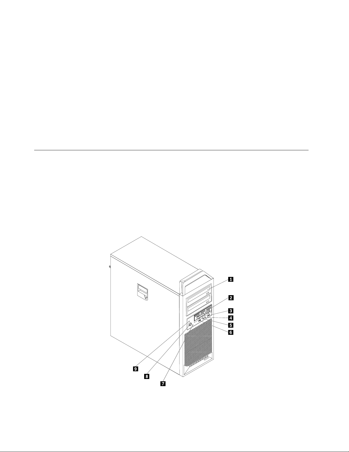
Figure1“Frontcontrolsandconnectors”onpage4showsthelocationoftheconnectorsonthefront
ofyourcomputer.
Note:Notallcomputermodelshavethefollowingcontrolsandconnectors.
Figure1.Frontcontrolsandconnectors
4ThinkStationHardwareInstallationandReplacementGuide
Page 11

1Opticaldrive(somemodels)6USBconnector
23.5-inchdiskettedriveorcardreader(some
7Harddiskdriveactivitylight
models)
3USBconnector
4Microphoneconnector9Power-onindicator
5Headphoneconnector
8Powerbutton
Locatingconnectorsontherearofyourcomputer
Figure2“Rearconnectorlocations”onpage5showsthelocationoftheconnectorsontherearofyour
computer.Someconnectorsontherearofyourcomputerarecolor-codedtohelpyoudeterminewhereto
connectthecablesonyourcomputer.
Figure2.Rearconnectorlocations
1Powercordconnector9Microphoneconnector
2Serialport
3Ethernetconnector11Audioline-outsidespeakerconnector
4Serialport(somemodels)12USBconnectors(8)
5Audioline-outsubwoofer/centerspeaker
10Audioline-outrearspeakerconnector
13OpticalSPDIFinconnector
connector
6Audioline-inconnector
7Videoconnector(somemodels)15eSA T Aconnector
8Audioline-outfrontspeakerconnector
14OpticalSPDIFoutconnector
Chapter2.Overview5
Page 12

ConnectorDescription
USBconnectorUsedtoattachadevicethatrequiresaUniversalSerialBus(USB)connector,
suchasaUSBkeyboard,aUSBmouse,aUSBscanner,oraUSBprinter.Ifyou
havemorethan10USBdevices,youcanpurchaseaUSBhub,whichyoucan
usetoconnectadditionalUSBdevices.
Ethernetconnector
Serialport
MicrophoneconnectorUsedtoattachamicrophonetoyourcomputerwhenyouwanttorecordsoundor
Audioline-inconnector
Audioline-outconnector(front
speakerconnector)
Audioline-outconnector
(subwoofer/centerspeaker
connector)
Audioline-outconnector(rear
speakerconnector)
Audioline-outconnector(side
speakerconnector)
OpticalSPDIFoutconnectorUsedtosend5.1digitalaudiosignalsfromacomputertoanexternaldevice(such
OpticalSPDIFinconnectorUsedtoreceive5.1digitalaudiosignalsfromexternalequipment(suchasa
eSATAconnectorUsethisexternalSerialAdvancedT echnologyAttachment(eSAT A)connector
UsedtoattachanEthernetcableforalocalareanetwork(LAN).
Note:TooperatethecomputerwithinFCCClassBlimits,useaCategory5
Ethernetcable.
Usedtoattachanexternalmodem,aserialprinter,orotherdevicesthatusea
9-pinserialport.
ifyouusespeech-recognitionsoftware.
Usedtoreceiveaudiosignalsfromanexternalaudiodevice,suchasastereo
system.Whenyouattachanexternalaudiodevicetoyourcomputer,connect
thecabletotheaudioline-outconnectorofthedeviceandtheaudioline-in
connectorofthecomputer.
Usedtosendaudiosignalsfromthecomputertoexternaldevices,such
aspoweredstereospeakers(speakerswithbuilt-inampliers),multimedia
keyboards,ortheaudioline-inconnectoronastereosystemorotherexternal
recordingdevices.
Whenusedwith5.1or7.1surroundspeakers,thisconnectorshouldbeattached
tothefrontleftandrightspeakers.
Whenusedwith5.1or7.1surroundspeakers,thisconnectorshouldbeattached
tothecenterspeakersandsubwoofer.
Whenusedwith5.1or7.1surroundspeakers,thisconnectorshouldbeattached
totherearleftandrightspeakers.
Whenusedwith7.1surroundspeakers,thisconnectorshouldbeattachedtothe
sideleftandrightspeakers.
asanamplierorareceiver)throughaTOSLINK(T oshibaLink)opticalcable.
receiverorothermultimediadevice)throughaTOSLINKopticalcable.
toattachanexternalharddiskdrive.
6ThinkStationHardwareInstallationandReplacementGuide
Page 13
Locatinginternalcomponents
Toremovethecomputercover,see“Removingthecomputercover”onpage11.
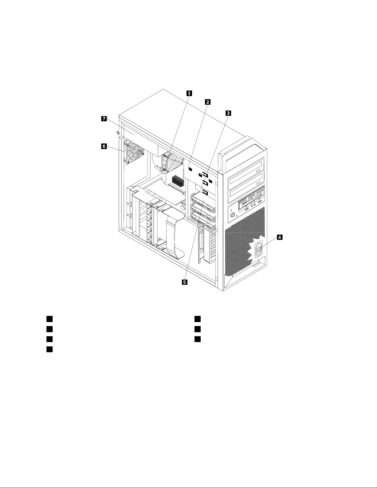
Figure3“Componentlocations”onpage7
showsthelocationofthecomponentsinyourcomputer.
Figure3.Componentlocations
1Microprocessor,heatsink,andheatsinkfanassembly
2Opticaldrive
33.5-inchdiskettedriveorcardreader7Powersupplyassembly
4Internalspeaker
5Harddiskdrive
6Rearfanassembly
Chapter2.Overview7
Page 14
Identifyingpartsonthesystemboard
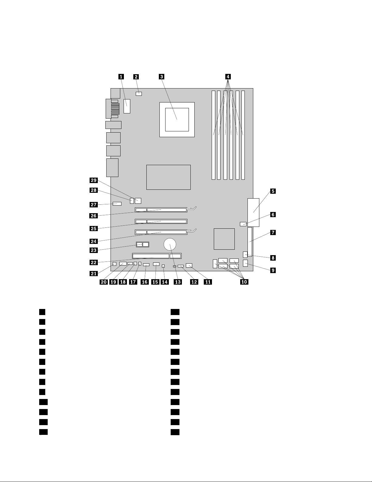
Figure4“Systemboardpartslocations”onpage8showsthelocationofthepartsonthesystemboard.
Figure4.Systemboardpartslocations
1Microprocessor12Vpowerconnector16Frontpanelconnector
2Microprocessorfanconnector
3Microprocessor18Thermalsensorconnector
4Memoryslots(6)19PS/2connector
524-pinsystempowerconnector20Frontaudioconnector
6Harddiskdrivefanassemblyconnector
7Diskettedriveconnector
8Cardreaderconnector23PCIExpressx1adaptercardslot
9FrontUSBconnector24PCIExpressx16graphicsadaptercardslot
10SA T Aconnectors(5)25PCIExpressx4adaptercardslot
11Adaptercardfanconnector
12SAS(SerialAttachedSCSI)LEDconnector27SecondCOMportconnector
13Battery
17Coverpresenceswitchconnector
21Internalspeakerconnector
22PCIadaptercardslot
26PCIExpressx16graphicsadaptercardslot
28Rearfanassemblyconnector
8ThinkStationHardwareInstallationandReplacementGuide
Page 15

14ClearCMOS/Recoveryjumper
15AuxiliaryLEDconnector
29Auxiliary12Vpowerconnector
Chapter2.Overview9
Page 16

10ThinkStationHardwareInstallationandReplacementGuide
Page 17
Chapter3.Installingoptionsandreplacinghardware
Thischapterisanintroductiontothefeaturesandoptionsthatareavailableforyourcomputer.Youcan
expandthecapabilitiesofyourcomputerbyaddingmemorymodules,adaptercards,ordrives.When
installinganoption,usetheseinstructionsalongwiththeinstructionsthatcomewiththeoption.
Attention:Donotopenyourcomputerorattemptanyrepairbeforereadingandunderstandingthe“Importantsafety
information”intheThinkStationSafetyandWarrantyGuidethatcamewithyourcomputer.T oobtainacopyofthe
ThinkStationSafetyandWarrantyGuide,goto:
http://support.lenovo.com
Note:UseonlypartsprovidedbyLenovo.
Installingexternaloptions
Externalspeakers,aprinter,orascannercanbeconnectedtoyourcomputer.Forsomeexternaloptions,
youmustinstalladditionalsoftwareinadditiontomakingthephysicalconnection.Whenaddinganexternal
option,see“Locatingconnectorsontherearofyourcomputer”onpage5
connectorsonthefrontofyourcomputer”onpage4toidentifytherequiredconnector,andthenusethe
instructionsthatareincludedwiththeoptiontohelpyoumaketheconnectionandinstallanysoftware
ordevicedriversthatarerequiredfortheoption.
Installinginternaloptions
and“Locatingcontrolsand
Important:Read“Handlingstatic-sensitivedevices”onpage3beforeremovingthecomputercover.
Removingthecomputercover
CAUTION:
Turnoffthecomputerandwaitthreetoveminutestoletthecomputercoolbeforeremovingthe
computercover.
Toremovethecomputercover:
1.Removeanymediafromthedrivesandshutdownyouroperatingsystem.Turnoffallattacheddevices.
Turnoffthecomputer.
2.Unplugallpowercordsfromelectricaloutlets.
3.Disconnectthecablesattachedtothecomputer.Thisincludespowercords,input/output(I/O)cables,
andanyothercablesthatareconnectedtothecomputer.See“Locatingcontrolsandconnectorsonthe
frontofyourcomputer”onpage4and“Locatingconnectorsontherearofyourcomputer”onpage5.
4.Removeanylockingdevices,suchasacablelockorpadlockthatsecuresthecomputercover.Open
thekeylockifitisinthelockedposition.SeeChapter5“Securityfeatures”onpage49.
©CopyrightLenovo2009,2011
11
Page 18
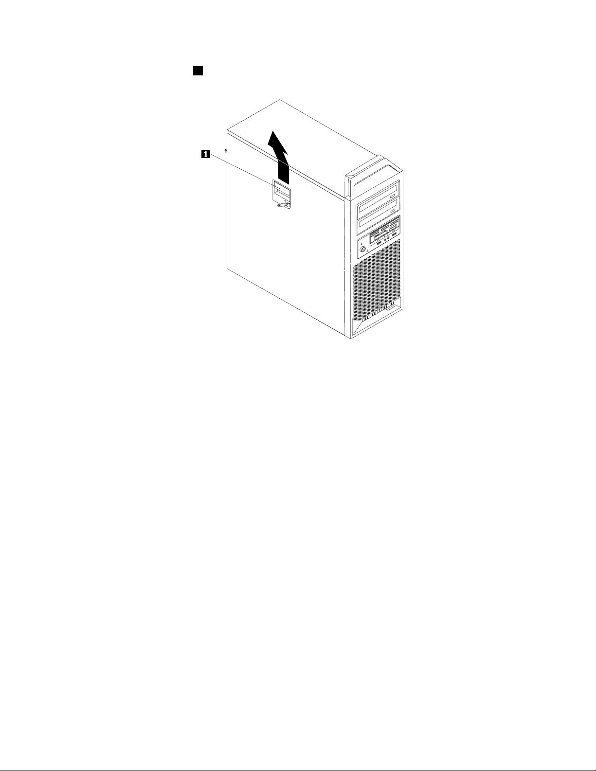
5.Disengagethecoverlatch1andremovethecover.Placethecoveronaatsurface.
Figure5.Removingthecomputercover
Removingthefrontbezel
Toremovethefrontbezel:
1.Removethecomputercover.See“Removingthecomputercover”onpage11.
12ThinkStationHardwareInstallationandReplacementGuide
Page 19
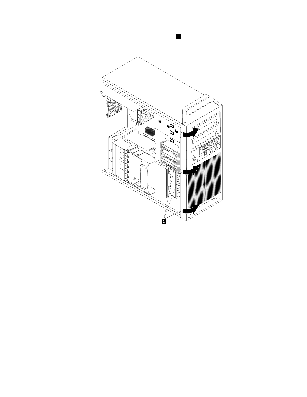
2.Removethefrontbezelbyreleasingthethreeplastictabs1ontheleftsideandpivotingthebezel
outward.
Figure6.Removingthefrontbezel
3.Laythefrontbezelonaatsurface.
4.Toreinstallthebezel,aligntheplastictabsontherightsideofthebezelwiththecorrespondingholesin
thechassis,thenpivotthebezelinwarduntilitsnapsintopositionontheleftside.
Accessingsystemboardcomponents
Toaccessthesystemboardcomponents:
1.Removethecomputercover.See“Removingthecomputercover”onpage11.
2.Unlatchandopentheadaptercardretainer.
3.Onsomemodels,youmightneedtoremovetheadaptercardstogaineasyaccesstosomeinternal
components.See“Replacinganadaptercard”onpage27.
Installingamemorymodule
YourcomputerhassixslotsforinstallingDDR3ECCUDIMMs(doubledatarate3errorcorrectioncode
unbuffereddualinlinememorymodules)thatprovideuptoamaximumof24GBofsystemmemory.
Wheninstallingmemorymodules,usethefollowingguidelines:
•Use1.8V ,240-pinDDR3ECCUDIMMs.
Chapter3.Installingoptionsandreplacinghardware13
Page 20
•Use1GB,2GBor4GBmemorymodulesinanycombinationuptoamaximumof24GB.
•Installmemorymodulesintothebluecolormemoryslotsrst.
Note:OnlyDDR3ECCUDIMMscanbeused.
Toinstallamemorymodule:
1.Removethecomputercover.See“Removingthecomputercover”onpage11.
Note:Forthisprocedure,ithelpstolaythecomputeronitsside.
2.Locatethememoryslots.See“Identifyingpartsonthesystemboard”onpage8.
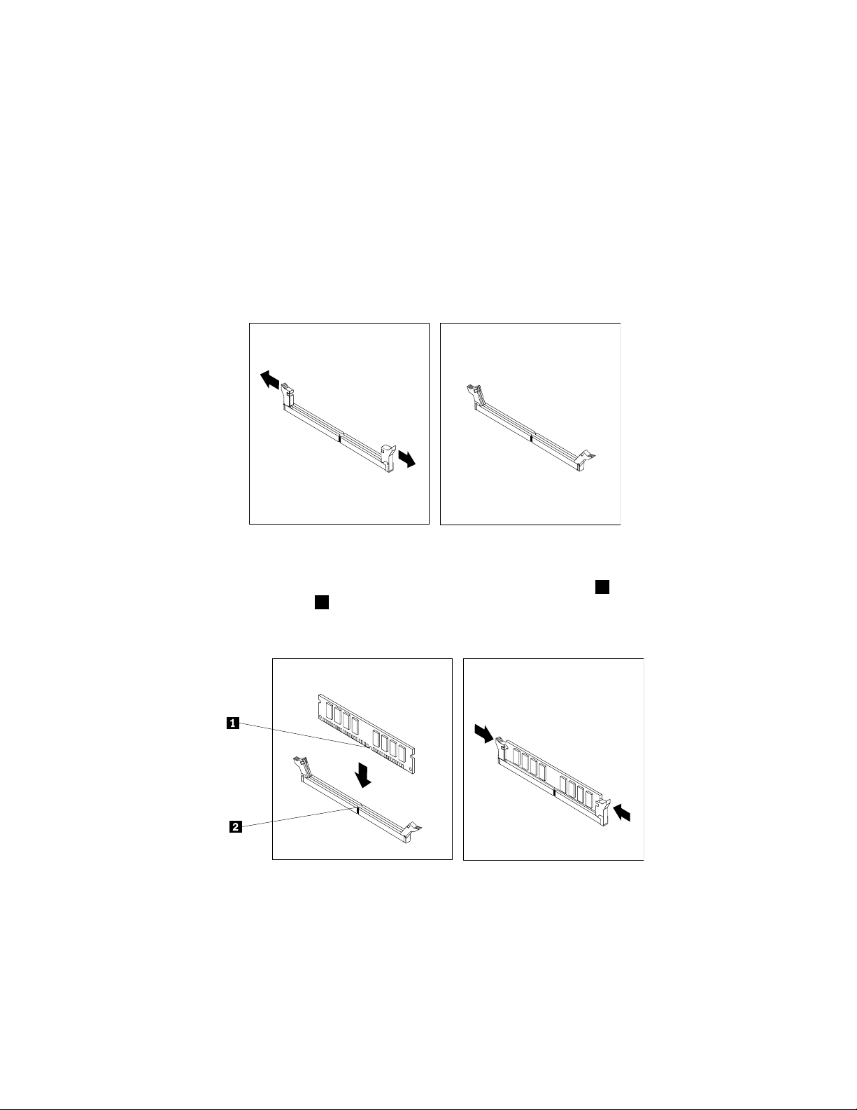
3.Opentheretainingclipsasshown.
Figure7.Openingtheretainingclips
4.Positionthenewmemorymoduleoverthememoryslot.Makesurethenotch1onthememorymodule
alignscorrectlywiththeslotkey
theslotuntiltheretainingclipsclose.
Figure8.Installingthememorymodule
5.GotoChapter4“Completingthepartsreplacement”onpage47.
2onthesystemboard.Pushthememorymodulestraightdowninto
Installinganadaptercard
Thissectionprovidesinformationandinstructionsforinstallinganadaptercard.
14ThinkStationHardwareInstallationandReplacementGuide
Page 21

Yourcomputerhasthefollowingveexpansionslotsforadaptercards:
•OnePCIadaptercardslot
•OnePCIExpressx1adaptercardslot
•OnePCIExpressx4adaptercardslot
•T woPCIExpressx16graphicsadaptercardslots
Toinstallanadaptercard:
1.Removethecomputercover.See“Removingthecomputercover”onpage11.
2.Unlatchandopenthecardretainer.
3.Removethemetalcoverfortheappropriateadaptercardslot.
4.Removetheadaptercardfromitsstatic-protectivepackage.
5.Installtheadaptercardintotheappropriateadaptercardslotonthesystemboard.See“Identifying
partsonthesystemboard”onpage8.
Figure9.Installinganadaptercard
Note:Ifyouareinstallingafulllengthadaptercard,extheadaptercardguidetowardthefrontofthe
chassisandthenaligntheendoftheadaptercardwiththeguides.Pushinwardandinstalltheadapter
cardintheslot.
Chapter3.Installingoptionsandreplacinghardware15
Page 22

6.Connectanyadaptercardcablestothesystemboard.
7.Latchtheadaptercardretainer.
Whattodonext:
•T oworkwithanotheroption,gototheappropriatesection.
•T ocompletetheinstallation,gotoChapter4“Completingthepartsreplacement”onpage47.
Installinginternaldrives
Thissectionprovidesinformationandinstructionsforinstallingtheinternaldrives.
Internaldrivesaredevicesthatyourcomputerusestoreadandstoredata.Youcanadddrivestoyour
computertoincreasestoragecapacityandtoenableyourcomputertoreadothertypesofmedia.Someof
thetypesofdrivesthatareavailableforyourcomputerare:
•SerialAttachedSCSI(SAS)harddiskdrives
•SerialATA(SA T A)harddiskdrives
•SA T Aopticaldrives,suchasCDdrivesorDVDdrives
•Removablemediadrives
Internaldrivesareinstalledinbays.Inthisbook,thebaysarereferredtoasbay1,bay2,andsoon.
Whenyouinstallaninternaldrive,itisimportanttonotethetypeandsizeofthedrivethatyoucaninstallin
eachbay.Also,itisimportanttocorrectlyconnecttheinternaldrivecablestotheinstalleddrive.
16ThinkStationHardwareInstallationandReplacementGuide
Page 23

Drivespecications
Yourcomputercomeswiththefollowingfactory-installeddrives:
•Anopticaldriveinbay1
•Ablankbayforexpansionoroptionalopticaldriveinbay2
•A3.5-inchdiskettedriveoracardreaderinbay3(somemodels)
•Uptothreeharddiskdrivesinbay4(variesbymodel)
Anybaythatdoesnothaveadriveinstalledhasastaticshieldandbaypanelinstalled.
Figure10“Drivebaylocations”onpage17
showsthelocationofthedrivebays.
Figure10.Drivebaylocations
Thefollowinglistdescribesthetypesandsizeofdrivesthatyoucaninstallineachbay:
1Bay1-Maximumheight:43mm(1.7inches)Opticaldrives,suchasCDdriveorDVDdrive
(preinstalledinsomemodels)
2Bay2-Maximumheight:43mm(1.7inches)OptionaldrivessuchasCDdriveorDVDdrive
(preinstalledinsomemodels)
3Bay3-Maximumheight:26.1mm(1inch)3.5-inchdiskettedriveorcardreader(preinstalled
insomemodels)
4Bay4
Uptothreeharddiskdrives(preinstalledinsome
models)
Chapter3.Installingoptionsandreplacinghardware17
Page 24

Installingadriveinbay1orbay2
Toinstallanopticaldriveinbay1orbay2:
1.Removethecomputercover.See“Removingthecomputercover”onpage11.
2.Removethefrontbezel.See“Removingthefrontbezel”onpage12.
Note:Thereisadriveretainerbracketontheinsideofthefrontbezelwherethedriveistobelocated.If
thereisnodriveinstalled,therearedriveretainerbracketsforeachdrive.Removethedriveretainer
bracketanduseittoinstallthedrive.
3.Removetheplasticdrivecoverfromthebezel.
4.Removethemetalstaticshieldfromthedrivebayusingyourngerstopullitoutward.
5.Installtheretainerbracketontheleftsideofthedrivetobeinstalled.
Figure11.Installingtheretainerbracket
6.Slidethedriveintothebayuntilitlocksintoposition.
Figure12.Installinganopticaldrive
18ThinkStationHardwareInstallationandReplacementGuide
Page 25

7.Toreinstallthefrontbezel,aligntheplastictabsontherightsideofthebezelwiththecorresponding
holesinthechassis,thenpivotthefrontbezelinwarduntilitsnapsintopositionontheleftside.
8.LocateanavailableSATAconnectoronthesystemboard.See“Identifyingpartsonthesystemboard”
onpage8.
9.Usingthesignalcablethatcamewiththenewdrive,connectoneendofthesignalcabletothedrive
andtheotherendtotheavailableSATAconnectoronthesystemboard.
10.Locateoneoftheextrave-wirepowercablesandconnectittothedrive.
Figure13.Connectingthedrive
Whattodonext:
•T oworkwithanotheroption,gototheappropriatesection.
•T ocompletetheinstallation,gotoChapter4“Completingthepartsreplacement”onpage47.
Installingadiskettedriveorcardreaderinbay3
Toinstalladiskettedriveorcardreaderinbay3:
1.Removethecomputercover.See“Removingthecomputercover”onpage11.
2.Removethefrontbezel.See“Removingthefrontbezel”onpage12.
3.Removetheplasticpanelinthebezelbysqueezingtheplastictabsthatsecurethepanelontheinside
ofthebezel.
Note:Ontheinsideofthefrontbezelwherethedriveistobelocatedthereisadriveretainerbracketfor
eachdrive.Removethedriveretainerbracketanduseittoinstallthedrive.
4.Installtheretainerbracketonthediskettedriveorcardreader.
Figure14.Installingtheretainerbracket
Chapter3.Installingoptionsandreplacinghardware19
Page 26

5.Slidethediskettedriveorcardreaderintothedrivebayuntilitsnapsintoposition.See“Locating
internalcomponents”onpage7.
Figure15.Installinganewdiskettedriveorcardreader
6.Connectthediskettedrivecabletothediskettedriveconnectoronthesystemboardandthenconnect
thepowercabletothediskettedrive.Ifyouareinstallingacardreader,connectittothecardreader
connectoronthesystemboard.See“Identifyingpartsonthesystemboard”onpage8.
7.Replacethefrontbezel.
Whattodonext:
•T oworkwithanotheroption,gototheappropriatesection.
•T ocompletetheinstallation,gotoChapter4“Completingthepartsreplacement”onpage47.
Installingaharddiskdriveinbay4
Thissectionprovidesinstructionsonhowtoinstallaharddiskdriveinbay4.
Notes:
•Y oucaninstallacombinationofSAT AandSASharddiskdriveswithinthesamecomputer.However,
SATAandSASharddiskdrivescannotbeinstalledwithinthesameRAIDarray.Alldrivesshouldbe
connectedtotheSAScontrollercard.
•MakesurethatyouhaveaSASadaptercardinstalledinyourcomputerbeforeyouinstallaSAShard
diskdrive.
20ThinkStationHardwareInstallationandReplacementGuide
Page 27

Toinstallanewharddiskdrive:
1.Removethecomputercover.See“Removingthecomputercover”onpage11.
2.Locateoneoftheemptyharddiskdriveslotsinbay4.See“Locatinginternalcomponents”onpage7.
Eachemptyharddiskdriveslothasasparebracket.
3.Pullthehandletoremoveasparebracket.
4.Toinstallthenewharddiskdriveintothebracket,exthebracket,andthenalignpin1,pin2,pin
3,andpin4onthebracketwiththeholesintheharddiskdrive.Donottouchthecircuitboard5
onthebottomoftheharddiskdrive.
Figure16.Installinga3.5-inchharddiskdriveintothebracket
Note:Ifyouareinstallinga2.5-inchharddiskdriveintothebracket,exthebracket,andthenalignpin
1,pin2,pin3,andpin4onthebracketwiththeholesintheharddiskdriveadapter5.
Figure17.Installinga2.5-inchharddiskdriveintothebracket
5.Installtheharddiskdriveandbracketintothedrivebay.
Chapter3.Installingoptionsandreplacinghardware21
Page 28

Figure18.Installingtheharddiskdriveandbracketintothedrivebay
6.Usingthesignalcablethatcamewiththenewdrive,connectoneendofthesignalcabletothedrive.
Locateoneoftheextrave-wirepowercablesandconnectittothedrive.
Note:ThesignalcablewillbedifferentdependingonwhetheryouareinstallingaSAT Aharddisk
driveoraSASharddiskdrive.
Figure19.Connectinga3.5-inchSATAharddiskdrive
22ThinkStationHardwareInstallationandReplacementGuide
Page 29

Figure20.Connectinga2.5-inchSATAharddiskdrive
Figure21.Connectinga3.5-inchSASharddiskdrive
7.IfyouareinstallingaSAT Aharddiskdrive,connecttheotherendofthesignalcabletooneofthe
availableSATAconnectorsonthesystemboard.IfyouareinstallingaSASharddiskdrive,connect
thesignalcabletooneoftheSASconnectorsontheSASadaptercard.See“Identifyingpartson
thesystemboard”onpage8.
Whattodonext:
•T oworkwithanotheroption,gototheappropriatesection.
•T ocompletetheinstallation,gotoChapter4“Completingthepartsreplacement”onpage47.
Replacingthebattery
Yourcomputerhasaspecialtypeofmemorythatmaintainsthedate,time,andsettingsforbuilt-infeatures,
suchasserial-portassignments(conguration).Abatterykeepsthisinformationactivewhenyouturn
offthecomputer.
Thebatterynormallyrequiresnochargingormaintenancethroughoutitslife;however,nobatterylasts
forever.Ifthebatteryfails,thedate,time,andcongurationinformation(includingpasswords)arelost.An
errormessageisdisplayedwhenyouturnonthecomputer.
Chapter3.Installingoptionsandreplacinghardware23
Page 30

Refertothe"Lithiumbatterynotice"intheThinkStationSafetyandWarrantyGuideforinformationabout
replacinganddisposingofthebattery.
Toreplacethebattery:
1.Turnoffthecomputeranddisconnectthepowercordfromtheelectricaloutletandfromthecomputer.
2.Openthecomputercover.See“Removingthecomputercover”onpage11.
3.Accessthesystemboard.See“Accessingsystemboardcomponents”onpage13.
4.Locatethebattery.See“Identifyingpartsonthesystemboard”onpage8.
5.Removetheoldbattery.
Figure22.Removingtheoldbattery
6.Installthenewbattery.
Figure23.Installingthenewbattery
7.Reinstallanyadaptercardthatwasremoved.Replacethecomputercoverandconnectthecables.
SeeChapter4“Completingthepartsreplacement”onpage47.
Note:Whenthecomputeristurnedonforthersttimeafterreplacingthebattery,anerrormessage
mightbedisplayed.Thisisnormalafterreplacingthebattery.
8.Turnonthecomputerandallattacheddevices.
9.UsetheSetupUtilityprogramtosetthedateandtimeandanypasswords.See"UsingtheSetup
Utility"intheThinkStationUserGuide.
Replacingthepowersupplyassembly
Attention:Donotopenyourcomputerorattemptanyrepairbeforereadingandunderstandingthe“Importantsafety
information”intheThinkStationSafetyandWarrantyGuidethatcamewithyourcomputer.T oobtainacopyofthe
ThinkStationSafetyandWarrantyGuide,goto:
http://support.lenovo.com
Toreplacethepowersupplyassembly:
24ThinkStationHardwareInstallationandReplacementGuide
Page 31

1.Removethecomputercoverandthenlaythecomputeronitsside.See“Removingthecomputer
cover”onpage11.
2.Locatethepowersupplyassembly.See“Locatinginternalcomponents”onpage7.
3.Disconnectthepowersupplycables
1 , and 3 fromthesystemboardconnectors.Disconnectthe
2 ,
powersupplycablesfromalladaptercards(somemodels)andfromalldrives.
Figure24.Powersupplycableconnectors
4.Removethepowersupplycablesfromanycableclipsandties.
Chapter3.Installingoptionsandreplacinghardware25
Page 32

5.Removethevescrewsattherearofthechassisthatsecurethepowersupplyassembly.
Figure25.Removingthepowersupplyretainingscrews
6.Depressthepowersupplyassemblylatch1.Slidethepowersupplyassemblytowardthefrontof
thecomputerandremoveitfromthechassis.
26ThinkStationHardwareInstallationandReplacementGuide
Page 33

Figure26.Removingthepowersupply
7.Ensurethatthenewpowersupplyisthecorrectreplacement.Somepowersuppliesautomatically
sensethevoltage,somepowersuppliesarevoltagespecic,andsomepowersupplieshavea
voltage-selectionswitch.Ifthereisavoltage-selectionswitch,useaballpointpentoslidetheswitch,if
necessary.
Note:Formodelsthathaveavoltage-selectionswitch:
•Ifthevoltagesupplyrangeis100–127VAC,settheswitchto115V.
•Ifthevoltagesupplyrangeis200–240VAC,settheswitchto230V.
8.Installthenewpowersupplyintothechassissothatthescrewholesinthepowersupplyalignwith
thoseinthechassis.
Note:UseonlythescrewsprovidedbyLenovo.
9.Installandtightenthevescrewsattherearofthechassistosecurethepowersupplyassembly.
10.Reconnectallpowersupplycablestothedrives,adaptercards,andthesystemboard.Makesureto
reconnectthepowercabletothegraphicscardsthatrequireanadditionalcable.
11.GotoChapter4“Completingthepartsreplacement”onpage47.
Replacinganadaptercard
Attention:Donotopenyourcomputerorattemptanyrepairbeforereadingandunderstandingthe“Importantsafety
information”intheThinkStationSafetyandWarrantyGuidethatcamewithyourcomputer.T oobtainacopyofthe
ThinkStationSafetyandWarrantyGuide,goto:
http://support.lenovo.com
Chapter3.Installingoptionsandreplacinghardware27
Page 34

Toreplaceanadaptercard:
1.Removethecomputercover.See“Removingthecomputercover”onpage11.
2.Unlatchandopentheadaptercardretainer.
3.Takenoteofthelocationofallcableconnectionsontheadaptercard.Itwillbenecessarytoreconnect
themproperlywheninstallinganewadaptercard.
4.Disconnectallcablesconnectedtotheadaptercard.See“Identifyingpartsonthesystemboard”
onpage8.
5.Releasetheadaptercardsupportretaininglatch1ifnecessary.Graspthefailingadaptercardand
pulltheadaptercardoutoftheslot.
Notes:
a.Theadaptercardtstightlyintothecardslot.Ifnecessary,alternatemovingeachsideoftheadapter
cardasmallamountuntilitisremovedfromtheadaptercardslot.
b.Somefulllengthadaptercardsaresecuredbytheadaptercardguide.Flextheadaptercardguide
towardsthefrontofthechassisandthengraspthefailingadaptercardtopullitoutoftheslot.
28ThinkStationHardwareInstallationandReplacementGuide
Page 35

6.Removethenewadaptercardfromitsstatic-protectivepackage.
7.Installthenewadaptercardintotheappropriateadaptercardslotonthesystemboard.See“Installing
anadaptercard”onpage14.
Chapter3.Installingoptionsandreplacinghardware29
Page 36

30ThinkStationHardwareInstallationandReplacementGuide
Page 37

Figure27.Installinganewadaptercard
8.Connectanyadaptercardcablestothesystemboard.
9.Latchtheadaptercardretainer.
10.GotoChapter4,Chapter4“Completingthepartsreplacement”onpage47.
Whattodonext:
•T oworkwithanotheroption,gototheappropriatesection.
•T ocompletetheinstallation,gotoChapter4“Completingthepartsreplacement”onpage47.
Replacingtheheatsinkandfanassembly
Attention:Donotopenyourcomputerorattemptanyrepairbeforereadingandunderstandingthe“Importantsafety
information”intheThinkStationSafetyandWarrantyGuidethatcamewithyourcomputer.T oobtainacopyofthe
ThinkStationSafetyandWarrantyGuide,goto:
http://support.lenovo.com
CAUTION:
Theheatsinkandfanassemblymightbeveryhot.Turnoffthecomputerandwaitthreetove
minutestoletthecomputercoolbeforeremovingthecomputercover.
Thissectionprovidesinstructionsonhowtoreplacetheheatsinkandfanassembly.
Chapter3.Installingoptionsandreplacinghardware31
Page 38

Toreplacetheheatsinkandfanassembly:
1.Removethecomputercover.See“Removingthecomputercover”onpage11.
2.Laythecomputeronitssideforeasieraccesstotheheatsinkandfanassembly.
3.Removetheheatsinkandfanassemblycablefromthesystemboard.Notethecablelocation.See
“Identifyingpartsonthesystemboard”onpage10.
4.Followthissequencetoremovethefourscrewsthatsecuretheheatsinkandfanassemblytothe
systemboard:
a.Partiallyremovescrew
1 ,thenfullyremovescrew 2 , andthenfullyremovescrew 1 .
b.Partiallyremovescrew3 ,thenfullyremovescrew 4 ,andthenfullyremovescrew 3 .
Note:Thefourscrewscanberemovedfromthesystemboard,buttheycannotberemovedfromthe
heatsinkandfanassembly.
Figure28.Removingtheheatsinkandfanassembly
5.Carefullylifttheheatsinkandfanassemblyoffthesystemboard.
Notes:
a.Y oumighthavetogentlytwisttheheatsinkandfanassemblytofreeitfromthemicroprocessor.
b.Donottouchthethermalgreasewhilehandlingtheheatsinkandfanassembly.
6.Removetheplasticcoverfromthebottomofthenewheatsinkandfanassemblytoexposethethermal
grease(thiscoverprotectsthethermalgreasefromcontamination).
Notes:
32ThinkStationHardwareInstallationandReplacementGuide
Page 39

a.Donotremovetheplasticcoveruntilyouarereadytoinstalltheheatsinkandfanassemblyon
themicroprocessor.
b.Donottouchthethermalgreaseontheheatsinkandfanassembly.
c.Donotputtheheatsinkandfanassemblyanywhereexceptonthemicroprocessoraftertheplastic
coverhasbeenremovedandthethermalgreaseexposed.
7.Positionthenewheatsinkandfanassemblyonthemicroprocessorsothatthefourscrewsarealigned
withtheholesonthesystemboard.
8.Followthissequencetoinstallthefourscrewstosecuretheheatsinkandfanassembly:
a.Partiallytightenscrew1,thenfullytightenscrew2,andthenfullytightenscrew1.
b.Partiallytightenscrew3,thenfullytightenscrew4,andthenfullytightenscrew3.
9.Connecttheheatsinkandfanassemblycabletothesystemboard.
10.GotoChapter4“Completingthepartsreplacement”onpage47.
Replacingaharddiskdrive
Attention:Donotopenyourcomputerorattemptanyrepairbeforereadingandunderstandingthe“Importantsafety
information”intheThinkStationSafetyandWarrantyGuidethatcamewithyourcomputer.T oobtainacopyofthe
ThinkStationSafetyandWarrantyGuide,goto:
http://support.lenovo.com
Thissectionprovidesinstructionsonhowtoreplacetheharddiskdrive.
Attention:YoucaninstallacombinationofSA T AandSASharddiskdriveswithinthesamecomputer.
However,SATAandSASharddiskdrivescannotbeinstalledwithinthesameRAIDarray.Alldrivesshould
beconnectedtotheSAScontrollercard.
Toreplaceaharddiskdrive:
1.Removethecomputercover.See“Removingthecomputercover”onpage11.
2.Locatetheharddiskdrive.See“Locatinginternalcomponents”onpage7.
3.Disconnectthesignalandpowercablesfromtheharddiskdrive.
Chapter3.Installingoptionsandreplacinghardware33
Page 40

4.Pullthehandleoftheharddiskdrivebrackettoremovetheharddiskdrive.
Figure29.Removingaharddiskdrive
5.Removethefailingharddiskdrivefromthebracketbyexingthebracket.
6.Installthenewharddiskdriveintothebracket.See“Installingaharddiskdriveinbay4”onpage20.
7.Installtheharddiskdriveandbracketintothedrivebay.
8.Connectthesignalandpowercablestothenewharddiskdrive.See“Installingaharddiskdrive
inbay4”onpage20.
9.GotoChapter4“Completingthepartsreplacement”onpage47.
Replacingtheharddiskdrivefanassembly
Attention:Donotopenyourcomputerorattemptanyrepairbeforereadingandunderstandingthe“Importantsafety
information”intheThinkStationSafetyandWarrantyGuidethatcamewithyourcomputer.T oobtainacopyofthe
ThinkStationSafetyandWarrantyGuide,goto:
http://support.lenovo.com
Yourcomputermighthaveaharddiskdrivefanassemblyinstalled.Toreplacetheharddiskdrivefan
assembly:
1.Removethecomputercover.See“Removingthecomputercover”onpage11.
2.Locatetheharddiskdrivefanassembly.Theharddiskdrivefanassemblyisattachedtothesideof
theharddiskdrivebay.
34ThinkStationHardwareInstallationandReplacementGuide
Page 41

3.Disconnecttheharddiskdrivefanassemblycablefromthesystemboard.See“Identifyingpartsonthe
systemboard”onpage10.
4.Pressthetwolatchesontheharddiskdrivefanassemblybracketandthenslidethefanassembly
bracketfreefromthechassis.
Figure30.Removingtheharddiskdrivefanassembly
5.Connectthenewharddiskdrivefanassemblycabletotheharddiskdrivefanassemblyconnector
onthesystemboard.
Chapter3.Installingoptionsandreplacinghardware35
Page 42

6.Installthenewharddiskdrivefanassemblybracketintothechassisbyaligningthefourlatches1on
thebracketwiththecorrespondingholesinthechassisandpushingthebracketinwarduntilitsnaps
intoposition.
Figure31.Installingtheharddiskdrivefanassembly
7.GotoChapter4“Completingthepartsreplacement”onpage47.
Replacinganopticaldrive
Attention:Donotopenyourcomputerorattemptanyrepairbeforereadingandunderstandingthe“Importantsafety
information”intheThinkStationSafetyandWarrantyGuidethatcamewithyourcomputer.T oobtainacopyofthe
ThinkStationSafetyandWarrantyGuide,goto:
http://support.lenovo.com
Thissectionprovidesinstructionsonhowtoreplacetheopticaldrive.
1.Removethecomputercover.See“Removingthecomputercover”onpage11.
2.Removethefrontbezel.See“Removingthefrontbezel”onpage12.
3.Locatetheopticaldrive.See“Locatinginternalcomponents”onpage7.
4.Notethelocationoftheopticaldrivecables.Disconnectthesignalandpowercablesfromtherearof
theopticaldrive.
36ThinkStationHardwareInstallationandReplacementGuide
Page 43

5.Pressthedrivelatch1andslidetheopticaldriveoutthefrontofthechassis.
Figure32.Removingtheopticaldrive
6.Removetheretainerbracketfromthedrivebeingreplacedandinstallitonthenewdrive.
Figure33.Retainerbracketforopticaldrive
7.Slidethenewopticaldriveintotheopticaldrivebayfromthefrontuntilitsnapsintoposition.
8.Reconnectthesignalandpowercablestothenewdrive.
9.GotoChapter4“Completingthepartsreplacement”onpage47.
Replacingthediskettedriveorcardreader
Attention:Donotopenyourcomputerorattemptanyrepairbeforereadingandunderstandingthe“Importantsafety
information”intheThinkStationSafetyandWarrantyGuidethatcamewithyourcomputer.T oobtainacopyofthe
ThinkStationSafetyandWarrantyGuide,goto:
http://support.lenovo.com
Chapter3.Installingoptionsandreplacinghardware37
Page 44

Thissectionprovidesinstructionsonhowtoreplacethediskettedriveorcardreader.
1.Removethecomputercover.See“Removingthecomputercover”onpage11.
2.Removethefrontbezel.See“Removingthefrontbezel”onpage12.
3.Locatethediskettedriveorcardreader.See“Locatinginternalcomponents”onpage7.
4.Disconnectthesignalandpowercablesfromtherearofthediskettedrive.Ifyouarereplacinga
cardreader,disconnectthecardreadercablefromthesystemboard.See“Identifyingpartsonthe
systemboard”onpage8.
5.Pressthedrivelatch1andslidethediskettedriveorcardreaderoutthefrontofthechassis.
Figure34.Removingthediskettedriveorcardreader
38ThinkStationHardwareInstallationandReplacementGuide
Page 45

6.Slidethenewdiskettedriveorcardreaderintothedrivebayuntilitsnapsintoposition.
Figure35.Installingadiskettedriveorcardreader
7.Connectthesignalcableandpowercabletothenewdiskettedrive.Ifyouareinstallingacardreader,
connectthecardreadercabletothecardreaderconnectoronthesystemboard.See“Identifying
partsonthesystemboard”onpage8.
8.GotoChapter4“Completingthepartsreplacement”onpage47.
Replacingthefrontpanelconnectorassembly
Attention:Donotopenyourcomputerorattemptanyrepairbeforereadingandunderstandingthe“Importantsafety
information”intheThinkStationSafetyandWarrantyGuidethatcamewithyourcomputer.T oobtainacopyofthe
ThinkStationSafetyandWarrantyGuide,goto:
http://support.lenovo.com
Thissectionprovidesinstructionsonhowtoreplacethefrontpanelconnectorassembly.
Toreplacethefrontpanelconnectorassembly:
1.Removethecomputercover.See“Removingthecomputercover”onpage11.
2.Removethefrontbezel.See“Removingthefrontbezel”onpage12.
3.Locatethefrontpanelconnectorassembly.
4.Disconnectthefrontaudio,frontUSB,andauxiliaryLEDcablesfromthesystemboardandnotethe
routesofthecables.See“Identifyingpartsonthesystemboard”onpage8.
Chapter3.Installingoptionsandreplacinghardware39
Page 46

5.Removethescrewthatsecuresthefrontpanelconnectorassemblytothechassis.Rotatetheassembly
tocompletelyreleaseitfromthechassis.
Figure36.Removingthefrontpanelconnectorassembly
6.Installthenewfrontpanelconnectorassemblyintothechassisandsecureitwiththescrew.
7.Reconnectallthecablestothesystemboard.See“Identifyingpartsonthesystemboard”onpage8.
8.GotoChapter4“Completingthepartsreplacement”onpage47.
Replacingamemorymodule
Attention:Donotopenyourcomputerorattemptanyrepairbeforereadingandunderstandingthe“Importantsafety
information”intheThinkStationSafetyandWarrantyGuidethatcamewithyourcomputer.T oobtainacopyofthe
ThinkStationSafetyandWarrantyGuide,goto:
http://support.lenovo.com
Thissectionprovidesinstructionsonhowtoreplaceamemorymodule.
Note:Y ourcomputerhassupportforsixmemorymodules.
1.Removethecomputercover.See“Removingthecomputercover”onpage11.
2.Locatethememorymoduleslots.See“Identifyingpartsonthesystemboard”onpage8.
40ThinkStationHardwareInstallationandReplacementGuide
Page 47

3.Removethememorymodulebeingreplacedbyopeningtheretainingclips.
Figure37.Removingamemorymodule
4.Positionthereplacementmemorymoduleoverthememoryslot.Makesurethenotch1onthememory
modulealignscorrectlywiththeslotkey2onthesystemboard.Pushthememorymodulestraight
downintotheslotuntiltheretainingclipsclose.See“Installingamemorymodule”onpage13.
Figure38.Installingthememorymodule
5.GotoChapter4Chapter4“Completingthepartsreplacement”onpage47.
Replacingthefrontandrearfanassemblies
Attention:Donotopenyourcomputerorattemptanyrepairbeforereadingandunderstandingthe“Importantsafety
information”intheThinkStationSafetyandWarrantyGuidethatcamewithyourcomputer.T oobtainacopyofthe
ThinkStationSafetyandWarrantyGuide,goto:
http://support.lenovo.com
Thissectionprovidesinstructionsonhowtoreplacethefrontandrearfanassemblies.
Toreplacetherearfanassembly:
1.Removethecomputercover.See“Removingthecomputercover”onpage11.
2.Locatethefanassemblythatyouwanttoreplace.Yourcomputerhasonefrontfanassemblyandone
rearfanassembly.See“Locatinginternalcomponents”onpage7.
Chapter3.Installingoptionsandreplacinghardware41
Page 48

3.Removethefrontbezelifyouarereplacingthefrontfanassembly.See“Removingthefrontbezel”
onpage12.
4.Disconnectthefanassemblycablefromthesystemboard.See“Identifyingpartsonthesystemboard”
onpage8.
5.Thefanassemblyisattachedtothechassisbyfourrubbermounts.Carefullyremovethefourrubber
mountsbybreakingthemorcuttingthemwithscissorsandthenremovethefanassemblyoutof
thechassis.
Figure39.Removingtherearfanassembly
6.Installthenewfanassemblybyaligningthefourrubbermountsofthefanassemblywiththeholeson
thechassisandpushtherubbermountsthroughtheholes.
7.Pullonthetipsoftherubbermountsuntilthefanassemblyisinplace.
8.Dependingonwhichfanassemblyyouarereplacing,reconnectthefanassemblycabletotheadapter
cardfanassemblyconnectorortherearfanassemblyconnectoronthesystemboard.See“Identifying
partsonthesystemboard”onpage8
.
9.Ifyouareinstallingtheharddiskdrivefanassembly,reinstallthefrontbezel.
10.GotoChapter4“Completingthepartsreplacement”onpage47.
Replacingtheinternalspeaker
Attention:Donotopenyourcomputerorattemptanyrepairbeforereadingandunderstandingthe“Importantsafety
information”intheThinkStationSafetyandWarrantyGuidethatcamewithyourcomputer.T oobtainacopyofthe
ThinkStationSafetyandWarrantyGuide,goto:
http://support.lenovo.com
Thissectionprovidesinstructionsonhowtoreplacetheinternalspeaker.
Toreplacetheinternalspeaker:
1.Removethecomputercover.See“Removingthecomputercover”onpage11.
42ThinkStationHardwareInstallationandReplacementGuide
Page 49

2.Removethefrontbezel.See“Removingthefrontbezel”onpage12.
3.Locatetheinternalspeakerconnectoronthesystemboard.See“Locatinginternalcomponents”
onpage9.
4.Notethelocationoftheinternalspeakercableconnection.Notetherouteoftheinternalspeaker
cable.Disconnecttheinternalspeakercablefromthesystemboard.See“Identifyingpartsonthe
systemboard”onpage10.
5.Useabluntinstrument(suchas,thetopofaballpointpen)todisengageoneoftheinternalspeaker
lockingtabs2andslidethatsideofthespeaker1upwardenoughtokeepthelockingtabdisengaged.
Thendisengagetheotherinternalspeakerlockingtabandslidetheinternalspeakerupwarduntil
thespeakerisreleased.
Figure40.Removingtheinternalspeaker
6.Removethespeakerandspeakercablefromthecomputer.
7.Routethenewspeakercableandthenpositionthenewinternalspeakertabs3intothemetalspeaker
slotsandthenpushtheinternalspeakerdownwarduntilthespeakerlockingtabssnapintoposition.
8.Connectthespeakercabletothesystemboard.See“Identifyingpartsonthesystemboard”onpage10.
9.GotoChapter4“Completingthepartsreplacement”onpage47.
Chapter3.Installingoptionsandreplacinghardware43
Page 50

Replacingthekeyboard
Attention:Donotopenyourcomputerorattemptanyrepairbeforereadingandunderstandingthe“Importantsafety
information”intheThinkStationSafetyandWarrantyGuidethatcamewithyourcomputer.T oobtainacopyofthe
ThinkStationSafetyandWarrantyGuide,goto:
http://support.lenovo.com
Thissectionprovidesinstructionsonhowtoreplaceakeyboard.
1.Removeanymediafromthedrives,shutdownyouroperatingsystem,andthenturnoffallattached
devicesandthecomputer.
2.Unplugallpowercordsfromelectricaloutlets.
3.Locatethekeyboardconnector.See“Locatingcontrolsandconnectorsonthefrontofyourcomputer”
onpage4or“Locatingconnectorsontherearofyourcomputer”onpage5.
Figure41.Keyboardconnector
4.Disconnectthefailingkeyboardcablefromthecomputer.
5.ConnectthenewkeyboardcabletooneoftheUSBconnectors.
6.GotoChapter4“Completingthepartsreplacement”onpage47.
Replacingthemouse
Attention:Donotopenyourcomputerorattemptanyrepairbeforereadingandunderstandingthe“Importantsafety
information”intheThinkStationSafetyandWarrantyGuidethatcamewithyourcomputer.T oobtainacopyofthe
ThinkStationSafetyandWarrantyGuide,goto:
http://support.lenovo.com
Thissectionprovidesinstructionsonhowtoreplaceamouse.
1.Removeallmedia(diskettes,discs,ortapes)fromthedrives,shutdownyouroperatingsystem,and
turnoffallattacheddevicesandthecomputer.
2.Unplugallpowercordsfromelectricaloutlets.
3.Locatetheconnectorforthemouse.See“Locatingcontrolsandconnectorsonthefrontofyour
computer”onpage4
or“Locatingconnectorsontherearofyourcomputer”onpage5.
44ThinkStationHardwareInstallationandReplacementGuide
Page 51

Figure42.Mouseconnector
4.Disconnectthefailingmousecablefromthecomputer.
5.ConnectthenewmousecabletooneoftheUSBconnectors.
6.GotoChapter4“Completingthepartsreplacement”onpage47.
Chapter3.Installingoptionsandreplacinghardware45
Page 52

46ThinkStationHardwareInstallationandReplacementGuide
Page 53

Chapter4.Completingthepartsreplacement
Aftercompletingallpartsreplacements,replacethecomputercoverandreconnectcables,including
telephonelinesandpowercords.Dependingonthepartsreplaced,youmightneedtoconrmtheupdated
informationintheSetupUtilityprogram.Referto"UsingtheSetupUtility"intheThinkStationUserGuide
forthisproduct.
Tocompletethepartsreplacement:
1.Ensurethatallcomponentshavebeenreassembledcorrectlyandthatnotoolsorloosescrewsare
leftinsideyourcomputer.See“Locatinginternalcomponents”onpage7forthelocationofvarious
components.
2.Makesurethatthecablesareroutedcorrectly.
Important:Correctlyrouteallpowersupplycables.Keepcablesclearofthehingesandsidesof
thecomputerchassis.
3.Replacethecomputercover.
a.Alignthecoverwiththechassis.
b.Closethecover.
c.Engagethecoverlatch.
d.Checktobesurethecoverislatched.
4.Ifacoverlockisinstalled,lockthecover.
5.Reconnecttheexternalcablesandpowercordstothecomputer.See“Locatingconnectorsontherear
ofyourcomputer”onpage5.
6.Toupdateyourconguration,see“UsingtheSetupUtility”intheThinkStationUserGuide.
Note:Inmostareasoftheworld,LenovorequiresthereturnofthedefectiveCRU.Informationaboutthiswill
comewiththeCRUorwillcomeafewdaysaftertheCRUarrives.
Obtainingdevicedrivers
Youcanobtaindevicedriversforoperatingsystemsthatarenotpreinstalledat:
http://support.lenovo.com
Installationinstructionsareprovidedinreadmeleswiththedevice-driverles.
©CopyrightLenovo2009,2011
47
Page 54

48ThinkStationHardwareInstallationandReplacementGuide
Page 55

Chapter5.Securityfeatures
Tohelppreventhardwaretheftandunauthorizedaccesstoyourcomputer,severalsecuritylockoptionsare
available.Inadditiontoaphysicallock,unauthorizeduseofyourcomputercanbepreventedbyasoftware
lockthatlocksthekeyboarduntilacorrectpasswordistypedin.
Makesurethatanysecuritycablesthatyouinstalldonotinterferewithothercomputercables.
Lockingdevices
Thissectiondescribesthedifferentkindsoflockingdevicesforthisproduct.
Figure43.Lockingdevices
Akeylock
therearofthemachine.Forsecurity,storethekeysinasecureplacewhenyouarenotusingthem.
Anoptionalpadlockwitha5mm(0.2inch)shacklecanbeusedtosecuretheproductcoverusingthe
padlockhasp
©CopyrightLenovo2009,2011
1comeswiththisproductbuiltintothesidecover.Thekeys3forthesidecoverareattachedto
2.
49
Page 56

Anoptionalintegratedcablelock4(sometimesreferredtoastheKensingtonlock)canbeusedtosecure
yourcomputertoadesk,table,orothernon-permanentxture.Thecablelockattachestoasecurityslotat
therearofyourcomputerandisoperatedwithakey.Thecablelockalsolocksthebuttonsusedtoopen
thecomputercover.Thisisthesametypeoflockusedwithmanynotebookcomputers.Y oucanordera
securitycabledirectlyfromLenovobysearchingonKensingtonat:
http://support.lenovo.com
Passwordprotection
Todeterunauthorizeduseofyourcomputer,youcanusetheSetupUtilityprogramtosetapassword.When
youturnonyourcomputer,youarepromptedtotypethepasswordtounlockthekeyboardfornormaluse.
Whattodonext:
•T oworkwithanotheroption,gototheappropriatesection.
•T ocompletetheinstallation,gotoChapter4“Completingthepartsreplacement”onpage47.
Erasingalostorforgottenpassword(clearingCMOS)
Thissectioncontainsinstructionsonerasingsomelostorforgottenpasswords,suchasauserpassword.
Toeraseaforgottenpassword:
1.Openthecomputercover.See“Removingthecomputercover”onpage11.
2.Accessthesystemboard.See“Accessingsystemboardcomponents”onpage13.
3.LocatetheClearCMOS/Recoveryjumperonthesystemboard.See“Identifyingpartsonthesystem
board”onpage8.
4.Movethejumperfromthestandardposition(pin1andpin2)tothemaintenanceorcongureposition
(pin2andpin3).
5.Reinstalltheadaptercardifremoved.
6.Replacethecomputercoverandconnectthepowercord.SeeChapter4“Completingtheparts
replacement”onpage47.
7.Restartthecomputer,leaveitonforapproximately10seconds.T urnoffthecomputerbyholdingthe
powerswitchforapproximatelyveseconds.Thecomputerwillturnoff.
8.Repeatsteps1throughstep3.
9.MovetheClearCMOS/Recoveryjumperbacktothestandardposition(pin1andpin2).
10.Reinstalltheadaptercardifremoved.
11.Replacethecomputercoverandconnectthepowercord.SeeChapter4“Completingtheparts
replacement”onpage47
.
50ThinkStationHardwareInstallationandReplacementGuide
Page 57

AppendixA.Systemmemoryspeed
TheIntelXeonmicroprocessorfamiliescompatiblewiththisThinkStationcomputerfeatureanintegrated
memorycontroller,whichprovidesthemicroprocessorwithdirectaccesstothesystemmemory.Because
ofthisdesign,thesystemmemoryspeedwillbedeterminedbyanumberoffactors,includingthe
microprocessormodelandthetype,speed,size(capacity),andnumberofDIMMsinstalled.Refertothe
followingtablefortheinformationonthesupportedsystemmemoryspeedforyourowncomputermodel.
Table1.DIMMtypeandspeed:PC3-10600U
DIMMsize(capacity)
1GB,2GB,4GB
NumberofDIMMs
installedperCPUbank
1to3
4to6
MicroprocessormodelMemoryfrequency
IntelXeonE5502,E5503,
E5504,E5506,E5507
IntelXeonE5520,E5530,
E5540,E5620,E5603,
E5606,E5607,E5630,
E5640,E5647,W3503,
W3505,W3520,W3530,
W3540,W3550,W3565,
W3670
IntelXeonE5645,E5649,
X5550,X5560,X5570,
X5650,X5660,X5667,
X5670,X5672,X5675,
X5677,X5680,X5687,
X5690,W3570,W3580,
W3680,W3690,W5580,
W5590
IntelXeonE5502,E5503,
E5504,E5506,E5507
IntelXeonE5520,E5530,
E5540,E5620,E5603,
E5606,E5607,E5630,
E5640,E5647,X5550,
X5560,X5570,W3503,
W3505,W3520,W3530,
W3540,W3550,W3565,
W3570,W3580,W3670,
W5580,W5590
IntelXeonE5645,E5649,
X5650,X5660,X5667,
X5670,X5672,X5675,
X5677,X5680,X5687,
X5690,W3680,W3690
800MHz
1066MHz
1333MHz
800MHz
1066MHz
1333MHz
©CopyrightLenovo2009,2011
51
Page 58

Table2.DIMMtypeandspeed:PC3-8500U
DIMMsize(capacity)
1GB,2GB,4GB
NumberofDIMMs
installedperCPUbank
1to6
MicroprocessormodelMemoryfrequency
IntelXeonE5502,E5503,
E5504,E5506,E5507
IntelXeonE5520,E5530,
E5540,E5620,E5603,
E5606,E5607,E5630,
E5640,E5645,E5647,
E5649,X5550,X5560,
X5570,X5650,X5660,
X5667,X5670,X5672,
X5675,X5677,X5680,
X5687,X5690,W3503,
W3505,W3520,W3530,
W3540,W3550,W3565,
W3570,W3580,W3670,
W3680,W3690,W5580,
W5590
800MHz
1066MHz
52ThinkStationHardwareInstallationandReplacementGuide
Page 59

AppendixB.Notices
Lenovomaynotoffertheproducts,services,orfeaturesdiscussedinthisdocumentinallcountries.Consult
yourlocalLenovorepresentativeforinformationontheproductsandservicescurrentlyavailableinyour
area.AnyreferencetoaLenovoproduct,program,orserviceisnotintendedtostateorimplythatonlythat
Lenovoproduct,program,orservicemaybeused.Anyfunctionallyequivalentproduct,program,orservice
thatdoesnotinfringeanyLenovointellectualpropertyrightmaybeusedinstead.However,itistheuser's
responsibilitytoevaluateandverifytheoperationofanyotherproduct,program,orservice.
Lenovomayhavepatentsorpendingpatentapplicationscoveringsubjectmatterdescribedinthis
document.Thefurnishingofthisdocumentdoesnotgiveyouanylicensetothesepatents.Y oucansend
licenseinquiries,inwriting,to:
Lenovo(UnitedStates),Inc.
1009ThinkPlace-BuildingOne
Morrisville,NC27560
U.S.A.
Attention:LenovoDirectorofLicensing
LENOVOPROVIDESTHISPUBLICATION“ASIS”WITHOUTWARRANTYOFANYKIND,EITHEREXPRESS
ORIMPLIED,INCLUDING,BUTNOTLIMITEDTO,THEIMPLIEDWARRANTIESOFNON-INFRINGEMENT,
MERCHANTABILITYORFITNESSFORAPARTICULARPURPOSE.Somejurisdictionsdonotallow
disclaimerofexpressorimpliedwarrantiesincertaintransactions,therefore,thisstatementmaynotapply
toyou.
Thisinformationcouldincludetechnicalinaccuraciesortypographicalerrors.Changesareperiodically
madetotheinformationherein;thesechangeswillbeincorporatedinneweditionsofthepublication.
Lenovomaymakeimprovementsand/orchangesintheproduct(s)and/ortheprogram(s)describedinthis
publicationatanytimewithoutnotice.
Theproductsdescribedinthisdocumentarenotintendedforuseinimplantationorotherlifesupport
applicationswheremalfunctionmayresultininjuryordeathtopersons.Theinformationcontainedinthis
documentdoesnotaffectorchangeLenovoproductspecicationsorwarranties.Nothinginthisdocument
shalloperateasanexpressorimpliedlicenseorindemnityundertheintellectualpropertyrightsofLenovo
orthirdparties.Allinformationcontainedinthisdocumentwasobtainedinspecicenvironmentsandis
presentedasanillustration.Theresultobtainedinotheroperatingenvironmentsmayvary.
Lenovomayuseordistributeanyoftheinformationyousupplyinanywayitbelievesappropriatewithout
incurringanyobligationtoyou.
Anyreferencesinthispublicationtonon-LenovoWebsitesareprovidedforconvenienceonlyanddonotin
anymannerserveasanendorsementofthoseWebsites.ThematerialsatthoseWebsitesarenotpartof
thematerialsforthisLenovoproduct,anduseofthoseWebsitesisatyourownrisk.
Anyperformancedatacontainedhereinwasdeterminedinacontrolledenvironment.Therefore,theresult
obtainedinotheroperatingenvironmentsmayvarysignicantly.Somemeasurementsmayhavebeen
madeondevelopment-levelsystemsandthereisnoguaranteethatthesemeasurementswillbethesame
ongenerallyavailablesystems.Furthermore,somemeasurementsmayhavebeenestimatedthrough
extrapolation.Actualresultsmayvary.Usersofthisdocumentshouldverifytheapplicabledatafortheir
specicenvironment.
©CopyrightLenovo2009,2011
53
Page 60

Televisionoutputnotice
Thefollowingnoticeappliestomodelsthathavethefactory-installedtelevision-outputfeature.
ThisproductincorporatescopyrightprotectiontechnologythatisprotectedbymethodclaimsofcertainU.S.
patentsandotherintellectualpropertyrightsownedbyMacrovisionCorporationandotherrightsowners.
UseofthiscopyrightprotectiontechnologymustbeauthorizedbyMacrovisionCorporation,andisintended
forhomeandotherlimitedviewingusesonlyunlessotherwiseauthorizedbyMacrovisionCorporation.
Reverseengineeringordisassemblyisprohibited.
Trademarks
ThefollowingtermsaretrademarksofLenovointheUnitedStates,othercountries,orboth:
Lenovo
TheLenovologo
ThinkStation
Othercompany,product,orservicenamesmaybetrademarksorservicemarksofothers.
54ThinkStationHardwareInstallationandReplacementGuide
Page 61

Index
A
adaptercards27
installing27
adaptercards,replacing14
audioline-inconnector6
audioline-outconnector6
B
battery,replacing23
bay4drive,installing19
C
cablelock,security49
cardreader,replacing37
CMOS,clearing50
components,accessingsystemboard13
components,internal7
computercover
removing11
connectordescription6
connectors
front4
rear5
CRU
completingtheinstallation47
D
devicedrivers47
devices,handlingstatic-sensitive3
diskettedrive,replacing37
drivers,device47
drives
bays17
internal16
specications17
E
eSAT Aconnector6
Ethernetconnector6
externaloptions,installing11
heatsinkandfanassembly,replacing31
I
importantsafetyinformation1
informationresources3
installing
bay4drive19
internaloptions11
installingoptions
adaptercards27
internaldrives16
memory13
securityfeatures49
internaloptions,installing11
internalspeaker,replacing42
K
keyboard,replacing44
L
locatingcomponents7
M
memoryspeed51
Microphoneconnector6
mouse,replacing44
N
notice,televisionoutput54
notices53
O
opticaldrive,replacing36
OpticalSPDIFinconnector6
OpticalSPDIFoutconnector6
options,installinginternaldrives16
outputnotice,television54
overview3
F
frontconnectors4
frontpanelconnectorassembly,replacing39
H
harddiskdrivefanassembly,replacing34
harddiskdrive,replacing33
©CopyrightLenovo2009,2011
P
partsreplacement,completing47
password
erasing50
lostorforgotten50
passwordprotection50
powersupply,replacing24
protection,password50
55
Page 62

R
rearconnectors5
rearfanassembly,replacing41
removingthecomputercover11
replacing
adaptercards14
battery23
harddiskdrive33
heatsinkandfanassembly31
internalspeaker42
resources,information3
S
safetyinformation1
security
cablelock49
features,installing49
serialport6
speed,memory51
static-sensitivedevices,handling3
systemboard
components,accessing13
identifyingparts8
location8
T
televisionoutputnotice54
trademarks54
U
USBconnector6
56ThinkStationHardwareInstallationandReplacementGuide
Page 63

Page 64

PartNumber:53Y4246
(1P)P/N:53Y4246
*53Y4246*
 Loading...