

Lenovo P70-A Service Manual

Index
Index .......................................................................................................................................... 1
1. Safety precautions .................................................................................................................. 2
2. Repair Tools ........................................................................................................................... 2
3. Wiring diagram ..................................................................................................................... 2
4. Power Voltage ........................................................................................................................ 3
5 Troubleshooting guide ............................................................................................................ 6
5.1 Power part ........................................................................................................................ 6
5.2 Not updating..................................................................................................................... 7
5.3 Display Trouble ................................................................................................................ 8
5.3.1 Backlight ................................................................................................................... 8
5.3.2 Display ...................................................................................................................... 9
5.4 Audio Trouble ................................................................................................................ 11
5.5 Function Trouble ............................................................................................................ 11
6. Block Diagram of The main board ...................................................................................... 12
页 1
4
4
3
KEY1
3
1 2
ADKEY_IN
PMIC_PWRON
2
PMIC_PWRON
ADKEY_IN
GND
ADKEY_IN
3
2
10ohm
K5
2
4
2
4
3
3
1
TS04BW0
1
1
GND
GND
R40
K6
2
TS04BW0
1
2
1
GND
4
4
3
3
GND
R48
K7
2
TS04BW0
1
10Kohm
2
1
GND
4
4
3
3
GND
1
A A
B B
C C
D D
4
4
3
1
2
3
4
5
EAR2
2
GND
GND
NC/T\POINT\R
HP_L
1
6
4
L
G
HP_R
3L5D2
HP_L
HP_R
R
3
2
CN8
1
A A
B B
HYX-ST35253
1
C C
D D

Attention: This service manual is only for service personnel to take reference with. Before
servicing please read the following points carefully.
1. Safety precautions
1.1 Be sure to switch off the power supply before replacing or welding any components or
inserting/plugging in connection wire.
1.2 Antistatic measures must be taken (throughout the entire production process!):
a)Do not touch here and there by hand at will;
b)Be sure to use antistatic electric iron;
c)It’s necessary for the welder to wear antistatic gloves.
1.3 Please refer to the part list before replacing components that have special safety requirements.
Do not replace with different components with different specs and type at will.
2. Repair Tools
Multimeter、Oscilloscope、DC power、 PC(Should be installed FLASH program)
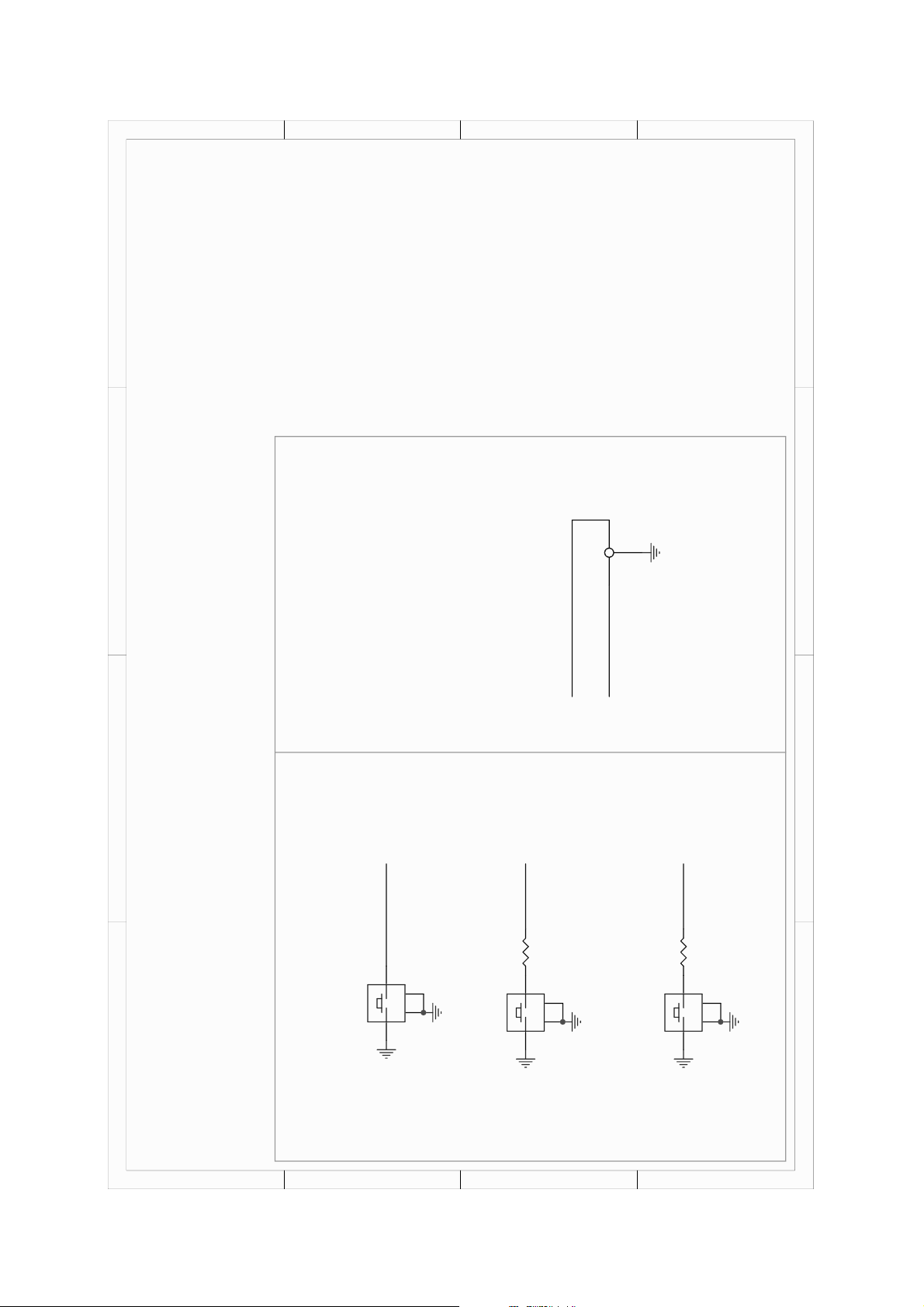
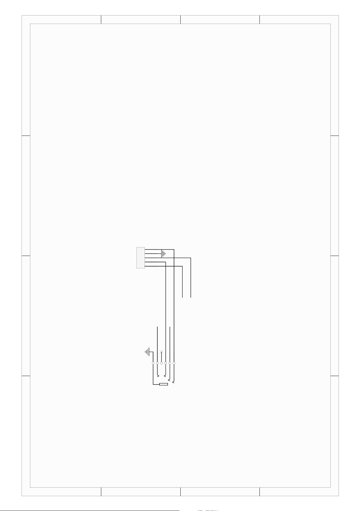
3. Wiring diagram
页 2

4. Power Voltage
4.1 U301 Output
Name Min. Typ. Max.
VPROC_PMU
VCORE_PMU
VM_PMU
VSRAM_PMU
VRF18_PMU
VIO18_PMU
VRF28_1_PMU
VRF28_2_PMU
VTCXO_1_PMU
VTCXO_2_PMU
VCAMA_PMU
VUSB_PMU
--
--
-- 1.35 --
--
1.8 1.825 1.85
1.75 1.8 1.85
2.7 2.85 3
2.7 2.85 3
2.7 2.8 2.9
2.7 2.8 2.9
2.65 2.8 2.95
3.1 3.3 3.5
1.15
1.05
1.15
--
--
--
VMC_PMU
VMCH_PMU
3.1 3.3 3.5
3.1 3.3 3.5
页 3
VGP1_PMU
3.1 3.3 3.5
VGP2_PMU
VGP3_PMU
VGP4_PMU
VSIM1_PMU
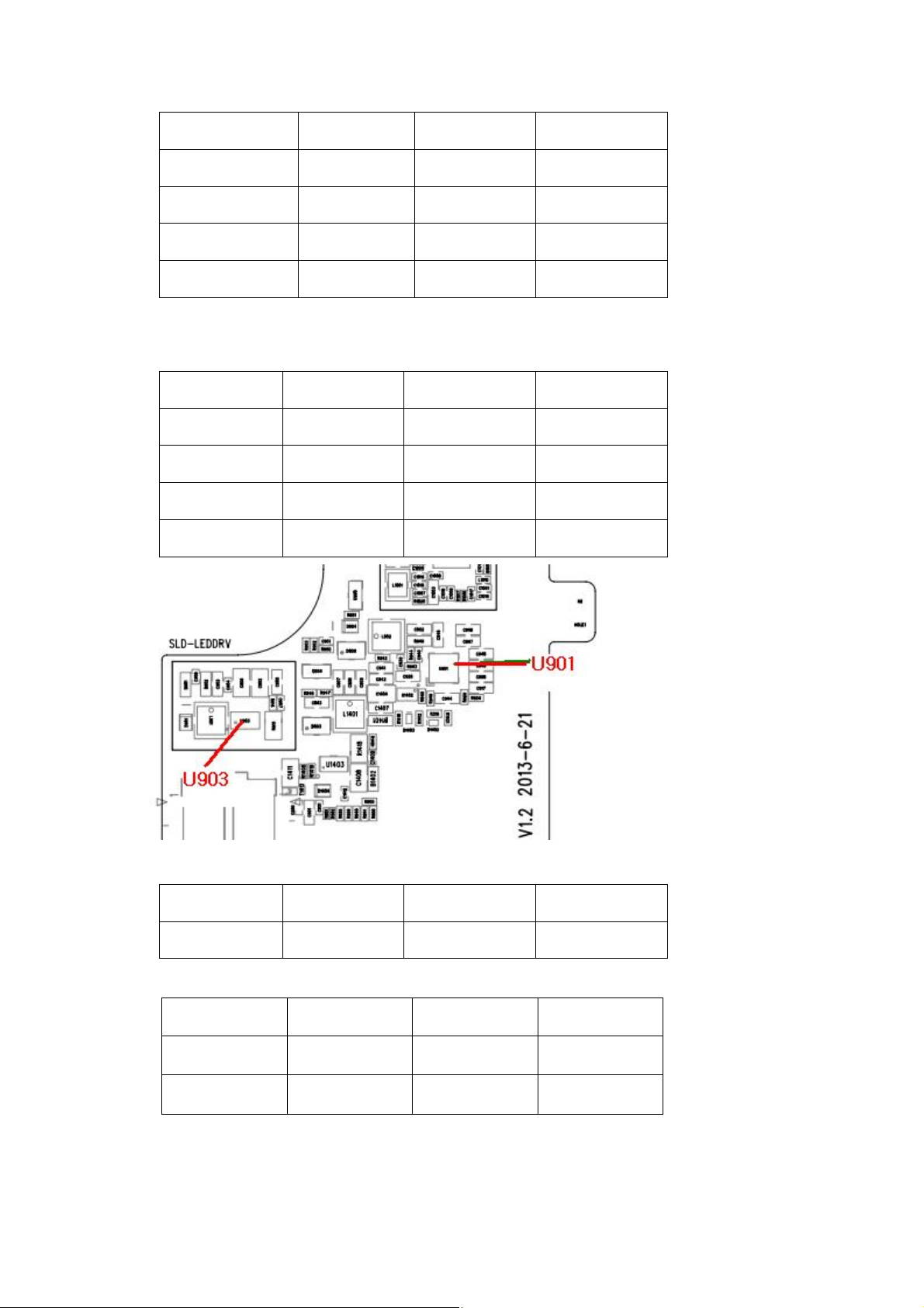
4.2 U901 Output
Name Min. Typ. Max.
AVDD 9.8 10 10.2
VCOM 2.6 3.6 4.6
VGL -8.1 -7.8 -7.5
VGH 18.6 18.9 19.2
1.7 1.8 1.9
2.65 2.8 2.95
1.7 1.8 1.9
3.1 3.3 3.5
4.3 U903 Output
Name Min. Typ. Max.
LED+ 8.4 -- 10.2
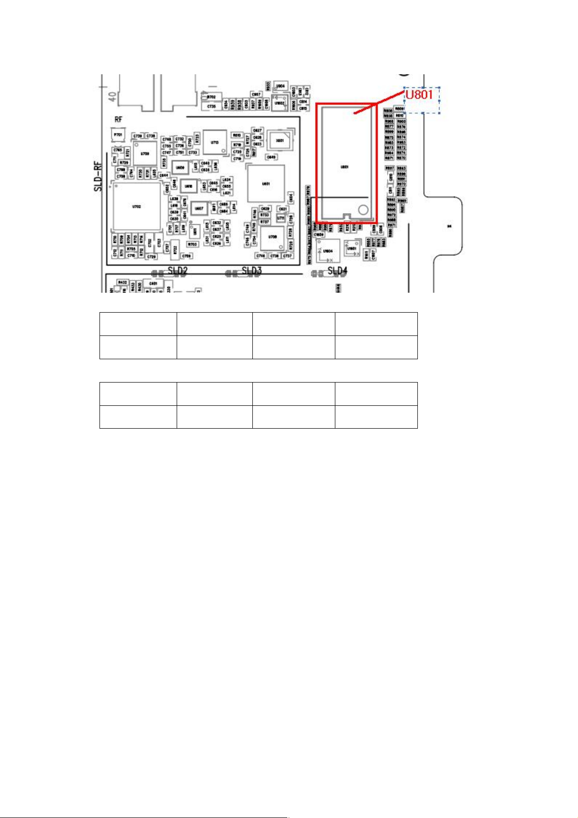
4.4 U801 Intput
Name Min. Typ. Max.
VDD 3 3.3 3.6
IOVCC 1.62 1.8 1.98
页 4
4.5 U1404 Output
Name Min. Typ. Max.
OUT 0 -- 2.8
4.6 U304 Intput
Name Min. Typ. Max.
VBUS 4.7 5 5.3
页 5
 Loading...