

Page 1

LenovoStorageN4610
UserGuideandHardwareMaintenance
Manual
MachineTypes:70G0and70G1
Page 2

Note:Beforeusingtheinformationandtheproductitsupports,besuretoreadandunderstandthefollowing:
•TheReadMeFirstthatcomeswithyourproduct
•“Safetyinformation”onpageiii
•AppendixA“Notices”onpage149
FirstEdition(February2015)
©CopyrightLenovo2015.
LIMITEDANDRESTRICTEDRIGHTSNOTICE:IfdataorsoftwareisdeliveredpursuantaGeneralServicesAdministration
“GSA”contract,use,reproduction,ordisclosureissubjecttorestrictionssetforthinContractNo.GS-35F-05925.
Page 3

Contents
Safetyinformation..........iii
Productsthatarenotassessed.........x
Safetyinspectionguide............x
Groundingrequirements............xi
Chapter1.Generalinformation.....1
Introduction.................1
Documentation...............2
Chapter2.Storageproductsetup
roadmap................5
Chapter3.Productoverview......7
Storageproductpackage...........7
Features..................7
Specifications...............11
Software.................13
BIOSandTSMupdateutilities.......13
LenovoThinkServerDeploymentManager..13
LenovoThinkServerSystemManager....14
LenovoThinkServerSystemManager
Premium...............14
Locations.................14
Machinetype,model,andserialnumber
label.................14
Frontviewofthestorageproduct.....15
Frontpanel..............16
Rearviewofthestorageproduct......18
Storageproductcomponents.......20
AnyRAIDadapterandHostBusAdapter...23
Hot-swap-drivebackplane........24
Systemboardcomponents........26
Systemboardjumpers..........29
SystemfanfaultLEDs..........31
Hot-swap-drivestatusLEDs.......32
PowersupplystatusLEDs........33
Connectingcables...........33
Chapter4.Turningonandturningoff
thestorageproduct..........35
Turningonthestorageproduct........35
Turningoffthestorageproduct........35
Chapter5.Configuringthestorage
product................37
UsingtheSetupUtilityprogram........37
StartingtheSetupUtilityprogram.....37
ViewinginformationintheSetupUtility
program...............37
SetupUtilityprograminterface......37
Settingthesystemdateandtime.....40
Usingpasswords............40
Selectingastartupdevice........41
SettinganEthernetconnectorforsystem
management.............42
ExitingtheSetupUtilityprogram......42
UpdatingorrecoveringtheBIOS......42
ConfiguringRAID..............44
AboutRAID..............44
ConfiguringRAIDusingtheLenovo
ThinkServerDeploymentManagerprogram.46
ConfiguringtheadvancedSATAorSAS
hardwareRAID.............46
Updatingthefirmware............46
Chapter6.Replacinghardware....49
Guidelines................49
Precautions..............49
Handlingstatic-sensitivedevices.....50
Systemreliabilityguidelines........50
Workinginsidethestorageproductwiththe
poweron...............51
Removingorextendingthestorageproductfrom
therackcabinet..............51
Removingthecover............51
Installing,removing,orreplacinghardware...53
Removingandreinstallingtherackhandles.53
Removingandreinstallingthecooling
shroud................54
Installingorreplacingasystemfan.....56
Removingandreinstallingthesystemfan
cage.................59
Installingorremovingamemorymodule...60
Replacingtherisercard.........68
InstallingorremovingaPCIExpresscard:
Ethernetcard,HostBusAdapter,andother
supportedtypesofPCIExpresscards...72
ReplacingtheAnyRAIDadapter......83
Installingorremovingtheflashmodule...85
InstallingorremovingtheThinkServerSystem
ManagerPremiummodule........88
InstallingorremovingtheAnyFabricadapter.90
Installingorreplacingahot-swapredundant
powersupply.............93
Installingorreplacingaheatsink......95
Installingorreplacingthemicroprocessor..97
©CopyrightLenovo2015
i
Page 4

InstallingorremovingtheThinkServerRAID
SuperCapacitorModule.........106
Installingorreplacingahot-swapdrive...108
Installinga2.5-inchsolid-statedriveintoa
3.5-inch-drivebay...........111
Installingorremovingtherearbackplane/cage
assembly...............114
Replacingthehot-swap-drivebackplane..116
Replacingthefrontpanelboard......120
Installngorremovingtheintrusionswitch..122
Replacingthecoin-cellbattery......125
Forservicetechnicianonly:replacingthe
systemboard.............127
Forservicetechnicianonly:replacingthe
powerdistributionboard.........131
Completingthepartsreplacement.......135
Reinstallingthecoverandreconnecting
cables................135
Updatingthestorageproductconfiguration..138
Chapter7.Troubleshootingand
diagnostics.............139
Troubleshootingprocedure..........139
ViewingthestatusanddiagnosticLEDs.....139
Viewingthesystemeventlog.........139
Basictroubleshootingtables.........140
LenovoThinkServerDeploymentManager
programproblems...........140
Storagedriveproblems.........140
Memorymoduleproblems........141
Keyboard,mouse,andUSBdevice
problems...............142
Informationresources............145
Usingthedocumentation.........145
LenovoStorageWebsite.........145
LenovoSupportWebsite.........145
Helpandservice..............146
Beforeyoucall.............146
Callingforservice............146
Usingotherservices..........147
Purchasingadditionalservices......147
AppendixA.Notices.........149
Trademarks................150
Importantnotes..............150
PolyvinylChloride(PVC)cableandcordnotice..150
Recyclinginformation............150
Batteryreturnprogram..........151
Requirementforbatteriescontaining
perchlorate..............151
RecyclinginformationforBrazil......152
Particulatecontamination..........152
ImportantWEEEinformation.........153
RestrictionofHazardousSubstancesDirective
(RoHS)..................153
EuropeanUnionRoHS..........153
GermanOrdinanceforWorkglossstatement...153
Exportclassificationnotice..........153
Electronicemissionnotices..........154
FederalCommunicationsCommission(FCC)
Statement...............154
Eurasiancompliancemark..........155
ENERGYSTARmodelinformation.......156
Chapter8.Gettinginformation,help,
andservice.............145
iiLenovoStorageN4610UserGuideandHardwareMaintenanceManual
Index.................157
Page 5
Safetyinformation
Note:Beforeusingtheproduct,besuretoreadandunderstandthemultilingualsafetyinstructionsonthe
documentationDVDthatcomeswiththeproduct.
Antesdeusaroproduto,leiaeentendaasinstruçõesdesegurançamultilínguesnoDVDdedocumentação
queoacompanha.
Предидаизползватетозипродукт,задължителнопрочететеивникнетевмногоезичнитеинструкции
забезопасноствDVDдискасдокументация,койтосепредоставяспродукта.
PrijeupotrebeovogproizvodaobaveznopročitajtevišejezičnesigurnosneuputekojesenalazenaDVD-us
dokumentacijomkojidobivateuzproizvod.
PředpoužitímproduktujetřebasipřečístaporozumětbezpečnostnímpokynůmuvedenýmnadiskuDVDs
dokumentací,kterýjedodávánsproduktem.
Førdubrugerproduktet,skaldusørgeforatlæseogforstådesikkerhedsforskrifter,derfindespåflere
sprog,pådendokumentations-dvd,derfølgermedproduktet.
LuetuotteenmukanatoimitetullaDVD-tietolevylläolevatmonikielisetturvaohjeetennentämäntuotteen
käyttöä.
Avantd'utiliserleproduit,veillezàbienlireetcomprendrelesinstructionsdesécuritémultilinguesfigurant
surleDVDdedocumentationfourniavecleproduit.
Πρινχρησιμοποιήσετετοπροϊόν,βεβαιωθείτεότιέχετεδιαβάσεικαικατανοήσειτιςοδηγίεςασφάλειας,οι
οποίεςείναιδιαθέσιμεςσεδιάφορεςγλώσσεςστοDVDτεκμηρίωσηςπουσυνοδεύειτοπροϊόν.
VorVerwendungdesProduktssolltenSieunbedingtdiemehrsprachigenSicherheitsanweisungenaufder
Dokumentations-DVDlesen,dieimLieferumfangdesProduktsenthaltenist.
AtermékhasználataelőttmindenképpenolvassaelésértelmezzeatermékhezkapottdokumentációsDVD
lemezentalálható,többnyelvenelolvashatóbiztonságielőírásokat.
Primadiutilizzareilprodotto,accertarsidileggereecomprendereleinformazionisullasicurezzamultilingue
disponibilisulDVDdidocumentazionefornitoconilprodotto.
製品をご使用になる前に、製品に付属のDocumentationDVDに収録されているマルチリンガルの「安
全に正しくご使用いただくために」を読んで理解してください。
제품을사용하기전에제품과함께제공되는문서DVD의다국어안전지침을주의깊게읽어보십시오.
Voordatuhetproductgebruikt,moetuervoorzorgendatudemeertaligeveiligheidsinstructiesopde
documentatie-dvdvanhetproducthebtgelezenenbegrijpt.
©CopyrightLenovo2015
iii
Page 6

Przedskorzystaniemzproduktunależyzapoznaćsięzwielojęzycznymiinstrukcjamibezpieczeństwa
znajdującymisięnapłycieDVDzdokumentacjądostarczonąwrazzproduktem.
Antesdeutilizaroproduto,leiaatentamenteasinstruçõesdesegurançamultilinguesqueconstamno
DVDdedocumentaçãofornecidocomoproduto.
Înaintedeautilizaprodusul,asiguraţi-văcăaţicititşiînţelesinstrucţiuniledesiguranţăînmaimultelimbide
peDVD-ulcudocumentaţiecareînsoţeşteprodusul.
Førdubrukerproduktet,måduleseogforstådenflerspråkligesikkerhetsinformasjonenpåDVDenmed
dokumentasjonsomfølgermedproduktet.
Преждечемиспользоватьэтотпродукт ,внимательноознакомьтесьсинструкциямипотехнике
безопасностинаразныхязыках,которыеможнонайтинаDVD-дискесдокументациейвкомплектес
продуктом.
在使用本产品之前,请务必先阅读和了解产品附带的文档DVD中的多语言安全说明。
Prenegotoupotrebiteproizvodobaveznopaljivoproitajteiprouiteviejezikouputstvozabezbednostna
dokumentacionomDVD-ukojistedobiliuzproizvod.
PredpouvanmproduktusipretajteviacjazynbezpenostnpokynynadiskuDVDsdokumentcioudodanoms
produktom.
Predenzačneteuporabljatiizdelek,jepomembno,daprebereteinrazumetevečjezičnavarnostnanavodila
naDVD-juzdokumentacijo,kistegaprejeliskupajzizdelkom.
Antesdeutilizarelproducto,asegúresedeleerycomprenderlasinstruccionesdeseguridadmultilingüesdel
DVDdedocumentaciónqueseproporcionaconelproducto.
Varnogamedattläsasäkerhetsinstruktionernapådokumentations-DVD-skivansomföljermedprodukten
innandubörjaranvändaprodukten.
使用本產品之前,請務必閱讀並瞭解產品隨附的文件DVD上的多國語言版本安全資訊。
Buürünükullanmadanönce,ürünlebirliktegönderilenbelgeDVD'siüzerindekiçokdiliçerengüvenlik
yönergeleriniokuyupanladýðýnýzdaneminolun.
Передвикористаннямцьогопродуктууважноознайомтесязінструкціямизтехнікибезпекинарізних
мовах,щоможназнайтинаDVD-дискуздокументацієювкомплектізпродуктом.
Important:Fortranslatedversionsofthecautionordangerstatement,refertotheSafety,Warranty,and
SupportInformationdocument.
Ensurethatyoureadandunderstandallcautionanddangerstatementsinthisdocumentbeforeyouperform
theprocedures.Readandunderstandanyadditionalsafetyinformationthatisincludedwiththestorage
oroptionaldevicebeforeyouinstall,remove,orreplacethedevice.
ivLenovoStorageN4610UserGuideandHardwareMaintenanceManual
Page 7
Statement1
DANGER
Electricalcurrentfrompower,telephone,andcommunicationcablesishazardous.
Toavoidashockhazard:
•Donotconnectordisconnectanycablesorperforminstallation,maintenance,orreconfigurationofthis
productduringanelectricalstorm.
•Connectallpowercordstoaproperlywiredandgroundedelectricaloutlet.
•Ensurethatallpowercordconnectorsaresecurelyandcompletelypluggedintoreceptacles.
•Connecttoproperlywiredoutletsanyequipmentthatwillbeattachedtothisproduct.
•Whenpossible,useonehandonlytoconnectordisconnectsignalcables.
•Neverturnonanyequipmentwhenthereisevidenceoffire,water,orstructuraldamage.
•Disconnecttheattachedpowercords,telecommunicationssystems,networks,andmodemsbeforeyou
openthedevicecovers,unlessinstructedotherwiseintheinstallationandconfigurationprocedures.
•Connectanddisconnectcablesasdescribedinthefollowingtablewheninstalling,moving,oropening
coversonthisproductorattacheddevices.
Toconnect:Todisconnect:
1.TurneverythingOFF .
2.First,attachallcablestodevices.
3.Attachsignalcablestoconnectors.
4.Attachpowercordstooutlets.
5.TurndevicesON.
1.TurneverythingOFF .
2.First,removepowercordsfromoutlets.
3.Removesignalcablesfromconnectors.
4.Removeallcablesfromdevices.
Statement2
DANGER
Dangerofexplosionifbatteryisincorrectlyreplaced.
Whenreplacingthelithiumcoincellbattery,useonlythesameoranequivalenttypethatis
recommendedbythemanufacturer .Thebatterycontainslithiumandcanexplodeifnotproperly
used,handled,ordisposedof.
Donot:
•Throworimmerseintowater
•Heattomorethan100°C(212°F)
•Repairordisassemble
Disposeofthebatteryasrequiredbylocalordinancesorregulations.
©CopyrightLenovo2015
v
Page 8
Statement3
CAUTION:
Whenlaserproducts(suchasCD-ROMs,DVDdrives,fiberopticdevices,ortransmitters)are
installed,notethefollowing:
•Donotremovethecovers.Removingthecoversofthelaserproductcouldresultinexposureto
hazardouslaserradiation.Therearenoserviceablepartsinsidethedevice.
•Useofcontrolsoradjustmentsorperformanceofproceduresotherthanthosespecifiedherein
mightresultinhazardousradiationexposure.
DANGER
SomelaserproductscontainanembeddedClass3AorClass3Blaserdiode.Notethefollowing:
Laserradiationwhenopen.Donotstareintothebeam,donotviewdirectlywithoptical
instruments,andavoiddirectexposuretothebeam.
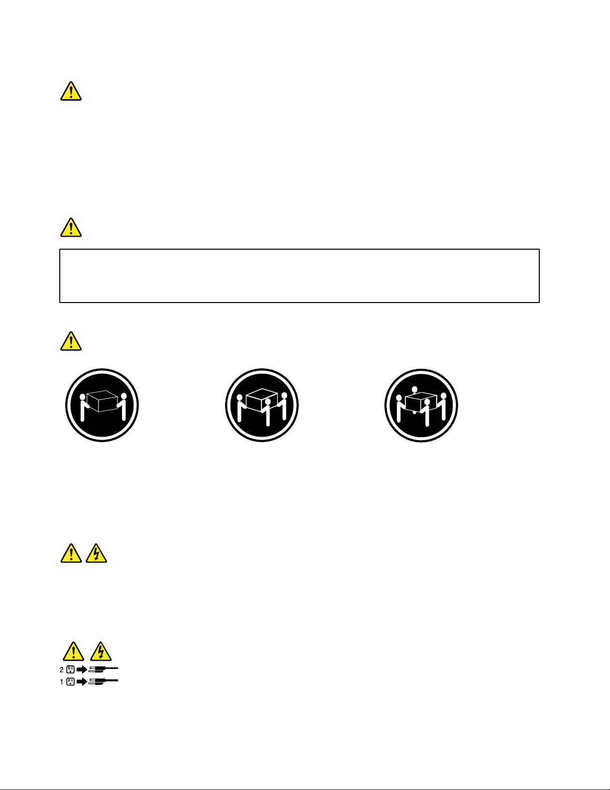
Statement4
≥18kg(39.7lb)≥32kg(70.5lb)≥55kg(121.2lb)
<32kg(70.5lb)<55kg(121.2lb)<100kg(220.5lb)
CAUTION:
Usesafepracticeswhenlifting.
Statement5
CAUTION:
Thepowercontrolbuttononthedeviceandthepowerswitchonthepowersupplydonotturnoff
theelectricalcurrentsuppliedtothedevice.Thedevicealsomighthavemorethanonepower
cord.T oremoveallelectricalcurrentfromthedevice,ensurethatallpowercordsaredisconnected
fromthepowersource.
viLenovoStorageN4610UserGuideandHardwareMaintenanceManual
Page 9
Statement6
CAUTION:
Ifyouinstallastrain-reliefbracketoptionovertheendofthepowercordthatisconnectedtothe
device,youmustconnecttheotherendofthepowercordtoapowersourcethatiseasilyaccessible
incaseitneedstobedisconnected.
Statement7
CAUTION:
Ifthedevicehasdoors,ensurethatyouremoveorsecurethedoorsbeforemovingorliftingthe
devicetoprotectagainstpersonalinjury.Thedoorswillnotsupporttheweightofthedevice.
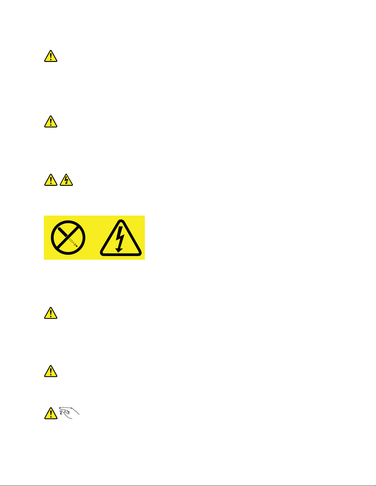
Statement8
CAUTION:
Neverremovethecoveronapowersupplyoranypartthathasthefollowinglabelattached.
Hazardousvoltage,current,andenergylevelsarepresentinsideanycomponentthathasthislabel
attached.Therearenoserviceablepartsinsidethesecomponents.Ifyoususpectaproblemwith
oneoftheseparts,contactaservicetechnician.
Statement9
CAUTION:
Disconnectthehot-swapfancablesbeforeremovingthefanfromthedevicetoprotectagainst
personalinjury.
Statement10
CAUTION:
Thefollowinglabelindicatesasharp-edgehazard.
©CopyrightLenovo2015
vii
Page 10
Statement11
CAUTION:
Thefollowinglabelindicatesapotentialheathazard.
Statement12
DANGER
Overloadingabranchcircuitisapotentialfirehazardandashockhazardundercertainconditions.To
avoidthesehazards,ensurethatyoursystemelectricalrequirementsdonotexceedbranchcurrentratings
attheinstallationsite.
Statement13
CAUTION:
Ensurethattherackissecuredproperlytoavoidtippingwhenthestorageunitisextendedontherails.
Statement14
CAUTION:
SomeaccessoryoroptionboardoutputsexceedClass2orlimitedpowersourcelimits.You
mustinstalltheappropriateinterconnectingcablinginaccordancewithyourlocalelectricalcode
requirements.
Statement15
CAUTION:
Thepower-controlbuttononthedevicemayputthedeviceinstandbymodeinsteadofturningoff
thedevice.Inaddition,thedevicemighthavemultipleconnectionstodcpower.T oremoveall
electricalcurrentfromthedevice,ensurethatallconnectionstodcpoweraredisconnectedat
thedcpowerinputterminals.
viiiLenovoStorageN4610UserGuideandHardwareMaintenanceManual
Page 11
Statement16
CAUTION:
Toreducetheriskofelectricshockorenergyhazards:
•Thisequipmentmustbeinstalledbytrainedservicepersonnelinarestricted-accesslocation,as
definedbyyourlocalelectricalcodeandthelatesteditionofIEC60950.
•Thebranchcircuitovercurrentprotectionmustberatedinaccordancewithlocalelectricalcode
requirements.
•Use1.3mm
2
or16AmericanWireGauge(AWG)copperconductoronly,notexceeding3meters
inlength.
•Torquethewiring-terminalscrewsto1.4newton-metersor12inch-pounds.
•Provideareadilyavailable,approvedandrateddisconnectdeviceinthefieldwiring.
Statement17
CAUTION:
ThisproductcontainsaClass1Mlaser.Donotviewdirectlywithopticalinstruments.
Statement18
CAUTION:
Donotplaceanyobjectontopofrack-mountedproducts.
Statement19
CAUTION:
Hazardousmovingparts.Keepfingersandotherbodypartsaway.
©CopyrightLenovo2015
ix
Page 12

Statement20
CAUTION:
Alithiumionbatteryisprovided.T oavoidpossibleexplosion,donotburnthebattery.Replacethe
batteryonlywiththeLenovo-approvedpart.Recycleordiscardthebatteryasinstructedbylocal
regulations.
Productsthatarenotassessed
Typicalproductsthatarenotassessedincludebutnotlimitedtothefollowing:
•StorageandIT-rackcomponents(forexample,uninterruptiblepowersuppliesandcurrentdistribution
systems)
•DevicesinITrooms(forexample,bulkstorageunitsandnetworkproducts)
•Industriallow-voltageswitchgear
Safetyinspectionguide
Thepurposeofthisinspectionguideistoassistyouinidentifyingpotentiallyunsafeconditions.Aseach
machinewasdesignedandbuilt,requiredsafetyitemswereinstalledtoprotectusersandservicetechnicians
frominjury.Thisguideaddressesonlythoseitems.Youshouldusegoodjudgmenttoidentifypotentialsafety
hazardsduetoattachmentofnon-LenovoStoragefeaturesoroptionsnotcoveredbythisinspectionguide.
Ifanyunsafeconditionsarepresent,youmustdeterminehowserioustheapparenthazardcouldbeand
whetheryoucancontinuewithoutfirstcorrectingtheproblem.
Considertheseconditionsandthesafetyhazardstheypresent:
•Electricalhazards,especiallyprimarypower(primaryvoltageontheframecancauseseriousorfatal
electricalshock)
•Explosivehazards,suchasadamagedCathodeRayTube(CRT)monitororabulgingcapacitor
•Mechanicalhazards,suchaslooseormissinghardware
Todeterminewhetherthereareanypotentiallyunsafeconditions,usethefollowingchecklistatthebeginning
ofeveryservicetask.Beginthecheckswiththepoweroff,andthepowercordsdisconnected.
Checklist:
1.Checkexteriorcoversfordamage(loose,broken,orsharpedges).
2.Poweroffthestorage.Disconnectthepowercords.
3.Checkthepowercordfor:
a.Athird-wiregroundconnectoringoodcondition.Useametertomeasurethird-wireground
continuityfor0.1ohmorlessbetweentheexternalgroundpinandtheframeground.
b.Thepowercordshouldbetheauthorizedtypespecifiedforyourstorage.Goto:
http://www.lenovo.com/serviceparts-lookup
c.Insulationmustnotbefrayedorworn.
4.Checkforcrackedorbulgingbatteries.
5.Removethecover.
6.Checkforanyobviousnon-LenovoStoragealterations.Usegoodjudgmentastothesafetyofany
non-LenovoStoragealterations.
xLenovoStorageN4610UserGuideandHardwareMaintenanceManual
Page 13

7.Checkinsidetheunitforanyobviousunsafeconditions,suchasmetalfilings,contamination,wateror
otherliquids,orsignsoffireorsmokedamage.
8.Checkforworn,frayed,orpinchedcables.
9.Checkthatthepower-supplycoverfasteners(screwsorrivets)havenotbeenremovedortamperedwith.
Groundingrequirements
Electricalgroundingofthestorageisrequiredforoperatorsafetyandcorrectsystemfunction.Proper
groundingoftheelectricaloutletcanbeverifiedbyacertifiedelectrician.
©CopyrightLenovo2015
xi
Page 14

xiiLenovoStorageN4610UserGuideandHardwareMaintenanceManual
Page 15

Chapter1.Generalinformation
Thischapterprovidessomegeneralinformationaboutyourproduct.
Thischaptercontainsthefollowingitems:
•“Introduction”onpage1
•“Documentation”onpage2
Introduction
ThisdocumentforyourLenovo
thestorageproductfeatures,specifications,componentlocations,configurationinstructions,hardware
replacementprocedures,andbasictroubleshootinganddiagnostics.
YourstorageproductcomeswithadocumentationDVDthatcontainsvariousstorageproductdocumentsto
helpyouuseandmaintainthestorageproduct.
TheLenovoLimitedWarranty(LLW)containsthewarrantytermsthatapplytotheproductyou
purchasedfromLenovo.ReadtheLLWonthedocumentationDVDthatcomeswithyourstorage
product.AprintablegenericversionofthelatestLLWalsoisavailableinmorethan30languagesat
http://www.lenovo.com/warranty/llw_02.IfyoucannotobtaintheLLWthroughthedocumentationDVDor
LenovoWebsite,contactyourlocalLenovoofficeorresellertoobtainaprintedversionoftheLLW,free
ofcharge.
®
network-attachedstorage(NAS)productcontainsinformationabout
Forwarrantyservice,consulttheworldwideLenovoSupporttelephonelist.T elephonenumbersaresubject
tochangewithoutnotice.Themostup-to-datetelephonelistforLenovoSupportisalwaysavailableonthe
Websiteathttp://www.lenovo.com/support/phone.Ifthetelephonenumberforyourcountryorregionisnot
listed,contactyourLenovoresellerorLenovomarketingrepresentative.
Toobtainthemostup-to-dateinformationaboutthestorageproduct,goto:
http://shop.lenovo.com/us/en/servers/network-storage/
LenovomaintainspagesontheWorldWideWeb,whereyoucangetthelatesttechnicalinformationand
downloaddocumentationordevicedriversandupdates.ToaccesstheLenovoSupportWebsite,goto:
http://www.lenovo.com/support
©CopyrightLenovo2015
1
Page 16

Recordinformationaboutyourstorageproductinthefollowingtable.Y ouwillneedtheinformationifyou
everneedtohaveyourstorageproductserviced.
Forwheretofindtheproductinformationlabelonthechassis,see“Machinetype,model,andserialnumber
label”onpage14
.
Productname
Machinetypeandmodel(MT-M)
Serialnumber(S/N)
Dateofpurchase
______________________________________________
______________________________________________
______________________________________________
______________________________________________
YoucanregisteryourstorageproductwithLenovobyfollowingtheinstructionsat:
http://www.lenovo.com/register
Whenyouregisteryourstorageproduct,informationisenteredintoadatabase,whichenablesLenovoto
contactyouincaseofarecallorothersevereproblem.AfteryouregisteryourstorageproductwithLenovo,
youwillreceivequickerservicewhenyoucallLenovoforhelp.Inaddition,somelocationsofferextended
privilegesandservicestoregisteredusers.
Documentation
Thistopicprovidesageneraldescriptionofeachdocumentforyourstorageproductandinstructionsonhow
toobtainallthedocuments.
Printeddocuments
Thefollowingdocumentsareprintedoutandincludedinyourstorageproductpackage.
•GettingStartedGuide
Thisdocumentprovidesgeneralinformationtohelpyougetfamiliarwithyourstorageproduct.
•RackInstallationInstructions(availableonsomemodels)
Thisdocumentprovidesinstructionsonhowtoinstallyourstorageproductintoastandardrackcabinet
byusingtherailkitshippedwiththestorageproduct.
Note:Dependingonthemodel,aprintedEnglishversionofthisdocumentmightbeincludedinyour
storageproductpackage.PDFversionsofotherlanguagesareprovidedonthedocumentationDVD
thatcomeswithyourstorageproduct.
2LenovoStorageN4610UserGuideandHardwareMaintenanceManual
Page 17

DocumentationDVD
ThedocumentationDVD,whichcomeswithyourstorageproduct,containsvariousdocumentsforyour
storageproductinPortableDocumentFormat(PDF)andHyperT extMarkupLanguage(HTML).The
documentationDVDisnotbootable.ToviewthedocumentsontheDVD,youwillneedacomputerwitha
WebbrowserandtheAdobeReaderprogram,whichisavailablefordownloadat:
http://www.adobe.com
TostartthedocumentationDVD,inserttheDVDintotheopticaldrive.TheDVDisAutoPlayenabledand
startsautomaticallyinmostMicrosoft
®
Linux
operatingsystem,openthelaunch.htmfilelocatedintherootdirectoryoftheDVD.
®
Windows
®
environments.IftheDVDfailstostartorifyouareusinga
Note:LenovomaintainspagesontheWorldWideWeb,whereyoucangetthelatesttechnicalinformation
anddownloaddocumentationordevicedriversandupdates.Someinformationinthedocumentsonthe
documentationDVDmightchangewithoutnoticeafterthefirstreleaseoftheDVD.Y oucanalwaysobtainall
themostup-to-datedocumentationforyourstorageproductfromtheLenovoWebsiteat:
http://www.lenovo.com/support
ThefollowingdocumentsareonthedocumentationDVDthatcomeswithyourstorageproduct:
•Safety,Warranty,andSupportInformation
Thisisamultilingualdocumentthatincludesallthesafetystatementsforyourproductinmorethan30
languages.Besuretoreadandunderstandallthesafetystatementsbeforeusingtheproduct.This
documentalsoincludestheLenovowarrantystatement,CustomerReplaceableUnits(CRUs)information,
andinformationabouthowtocontacttheLenovoCustomerSupportCenter.
•LenovoLicenseAgreement
ThisdocumentincludesthetermsandconditionsoftheLenovoLicenseAgreement.
•UserGuideandHardwareMaintenanceManual
Thisdocumentprovidesdetailedinformationtohelpyougetfamiliarwithyourstorageproductandhelp
youuse,configure,andmaintainyourstorageproduct.
•RackInstallationInstructions
Thisdocumentprovidesinstructionsonhowtoinstallyourstorageproductintoastandardrackcabinet
byusingtherailkitshippedwiththestorageproduct.
•NASAdministratorGuide
Thisdocumentprovidesinstructionsonhowtomanageyourstorageproductusingtheprogramsand
utilitiesthatcomewiththeMicrosoftWindowsStorageServer2012R2operatingsystem.
Chapter1.Generalinformation3
Page 18

4LenovoStorageN4610UserGuideandHardwareMaintenanceManual
Page 19

Chapter2.Storageproductsetuproadmap
Thischapterprovidesageneralroadmaptoguideyouthroughsettingupyourstorageproduct.
Thestorageproductsetupprocedurevariesdependingontheconfigurationofthestorageproductwhen
itwasdelivered.Insomecases,thestorageproductisfullyconfiguredandyoujustneedtoconnectthe
storageproducttothenetworkandanacpowersource,andthenyoucanturnonthestorageproduct.In
othercases,thestorageproductneedstohavehardwaredevicesinstalled,requireshardwareandfirmware
configuration,andrequiresanoperatingsystemtobeinstalled.
Thegeneralprocedureforsettingupyourstorageproductis:
1.Unpackthestorageproductpackage.See“Storageproductpackage”onpage7.
2.Installanyrequiredhardwareorstorageproductoptions.SeetherelatedtopicsinChapter6“Replacing
hardware”onpage49.
3.Ifnecessary,installthestorageproductintoastandardrackcabinetbyusingtherailkitshippedwith
thestorageproduct.SeetheRackInstallationInstructionsthatcomeswiththestorageproduct.
4.ConnecttheEthernetcablesandpowercordstothestorageproduct.See“Rearviewofthestorage
product”onpage18
5.Turnonthestorageproducttoverifyoperation.See“Turningonthestorageproduct”onpage35.
6.ReviewtheBasicInputOutputSystem(BIOS)settingsandcustomizeasneeded.See“UsingtheSetup
Utilityprogram”onpage37
7.ConfigureRAIDandinstalltheoperatingsystemanddevicedrivers.See“LenovoThinkServer
DeploymentManager”onpage13
8.Installanyadditionaldriversrequiredforaddedfeatures.Refertotheinstructionsthatcomewith
thehardwareoption.
9.ConfigureEthernetsettingsintheoperatingsystembyreferringtotheoperatingsystemhelp.This
stepisnotrequirediftheoperatingsystemwasinstalledusingtheLenovoThinkServerDeployment
Managerprogram.
10.Checkforfirmwareupdates.See“Updatingthefirmware”onpage46.
11.Installmanagementapplicationsandanyotherapplications.Refertothedocumentationthatcomes
withtheapplicationsthatyouwanttoinstall.
tolocatetheconnectors.
.
and“ConfiguringRAID”onpage44.
©CopyrightLenovo2015
5
Page 20

6LenovoStorageN4610UserGuideandHardwareMaintenanceManual
Page 21

Chapter3.Productoverview
Thischapterprovidesinformationaboutthestorageproductpackage,features,specifications,software
programs,andcomponentlocations.
Thischaptercontainsthefollowingitems:
•“Storageproductpackage”onpage7
•“Features”onpage7
•“Specifications”onpage11
•“Software”onpage13
•“Locations”onpage14
Storageproductpackage
Thestorageproductpackageincludesthefollowingitems:
•Storageproduct
•Railkit(availableonsomemodels)
•Cablemanagementarmorcablemanagementbar(availableonsomemodels)
•Materialbox,includingitemssuchaspowercords,printeddocumentation,andadocumentationDVD
Features
Thistopicprovidesgeneralinformationaboutthestorageproductfeaturesforavarietyofmodels.Depending
onyourspecificmodel,somefeaturesmightvaryorunavailable.Forinformationaboutyourspecificmodel,
usetheSetupUtilityprogram.See“ViewinginformationintheSetupUtilityprogram”onpage37
canrefertotheProductSpecificationsReferencedocumentforLenovoStorageproductsat:
http://www.lenovo.com/psref/
Microprocessor
OneortwoIntel
Foralistofstorageproductoptions,goto:
http://shop.lenovo.com/us/en/servers/network-storage/
Memory
Yourstorageproducthas24memoryslots.Formoreinformation,see“Memorymoduleinstallationrules”
onpage61.
Powersupply
•Oneortwo550-watthot-swapredundantpowersupplies(Universalinputandcompliantwith80PLUS
Platinum)
•Oneortwo750-watthot-swapredundantpowersupplies(Universalinputandcompliantwith80PLUS
Platinum)
•Oneortwo750-watthot-swapredundantpowersupplies(Highlineinputandcompliantwith80PLUS
Titanium)
®
®
Xeon
microprocessors(internalcachesizevariesbymodel)
.Youalso
©CopyrightLenovo2015
7
Page 22

Systemfans
Yourstorageproductsupportsuptosixhot-swapsystemfans.Thisdesignhelpsyouavoidsignificant
coolingproblemswhenasystemfanfails.Youcanreplaceasystemfanwithoutturningoffthestorage
product.Tolocatethesystemfans,see“Systemboardcomponents”onpage26
.
•Ifyourstorageproductisinstalledwithonemicroprocessor,foursystemfans(fan1tofan4)areadequate
toprovidepropercooling.However,youmustkeepthelocationsforfan5andfan6occupiedbydummy
fanstoensureproperairflow.
•Ifyourstorageproductisinstalledwithtwomicroprocessors,ensurethatallthesixsystemfansare
installedtoavoidcoolingproblems.
Internaldrives
Internaldrivesaredevicesthatyourstorageproductusestoreadandstoredata.Theinternaldrives
supportedbyyourstorageproductvarybymodel.
•Inthefront:
DrivebaysizeDrivebayquantityDrivetype
Hot-swap,SA TAorSAS
3.5-inch12
3.5-inchharddiskdriveor2.5-inchsolid-state
drive
Note:Youcaninstalla2.5-inchsolid-statedriveintoa3.5-inch-drivebay.Formoreinformation,see
“Installinga2.5-inchsolid-statedriveintoa3.5-inch-drivebay”onpage111.
•Intherear:
DrivebaysizeDrivebayquantityDrivetype
Hot-swap,SATA
2.5-inch2
Harddiskdriveorsolid-statedrive
Notes:
•SATAistheacronymforSerialAdvancedTechnologyAttachment.
•SASstandsforSerialAttachedSCSI(SCSIistheacronymforSmallComputerSystemInterface).
•YoucaninstallSATAharddiskdrives,SASharddiskdrives,andsolid-statedrivesintothesamestorage
product.
Expansionslots
•Tworisercardassemblyslotsonthesystemboard
•ThreePCIExpress(PCIe)slotsonsystemboard
•ThreePCIeslotsontherisercard
•OneAnyFabricslotintherearofthestorageproduct
Fordetailedinformation,see“Rearviewofthestorageproduct”onpage18.
8LenovoStorageN4610UserGuideandHardwareMaintenanceManual
Page 23

Input/Output(I/O)features
Ontherearpanel:
•OneDisplayPort®connector
•OneRJ-45Ethernetconnector
•Oneserialconnector
•TwoUSB3.0connectors
Note:Ifyouuseavideographicsarray(VGA)monitor,itisrecommendedthatyoupurchaseacompatible
DisplayPorttoVGAadapterfromLenovo.
Tolocatetheconnectors,refertotherelatedtopicsin“Locations”onpage14.
Videosubsystem
AnintegratedgraphicscontrollerisavailableinyourstorageproducttosupporttheDisplayPortconnectors
forconnectingvideodevices.TheintegratedgraphicscontrollerislocatedintheBaseboardManagement
Controller(BMC)chiponthesystemboard.
•Integratedgraphicscontroller:On-boardASPEEDAST2400
•16MBofvideomemorycache
Ethernetconnectivity
ThereisoneRJ-45Ethernetconnectorontherearpanelwith10megabitspersecond(Mbps),100Mbps,or
1000Mbpsnetworkconnectivity.TheEthernetconnectorisforsystemmanagement.
YoucaninstallanEthernetcardoranAnyFabricadaptertoenablemoreEthernetconnectors.However,you
mustinstalladevicedrivertoenabletheoperatingsystemtorecognizetheEthernetconnectors.Thedevice
driversareavailablefordownloadat:
http://www.lenovo.com/drivers
Formoreinformation,see“Rearviewofthestorageproduct”onpage18
.
Reliability,availability,andserviceability
Reliability,availability,andserviceability(hereinafterreferredtoasRAS)arethreeimportantstorageproduct
designfeatures.TheRASfeatureshelpyoutoensuretheintegrityofthedatastoredonthestorageproduct,
theavailabilityofthestorageproductwhenyouneedit,andtheeasewithwhichyoucandiagnoseand
correctproblems.
YourstorageproducthasthefollowingRASfeatures:
Chapter3.Productoverview9
Page 24

•Securityfeatures
–Administratorpasswordanduserpasswordtohelpprotectunauthorizedaccesstothestorageproduct
(see“Usingpasswords”onpage40
)
–Remotemonitoringorcontrolbyanadministratortoprovideprotectionorhelp
–Hot-swapredundantpowersuppliestohelpavoidsignificantinterruptiontotheoperationofthe
systemwhenapowersupplyfails
–Sixhot-swapsystemfanswithredundancytohelpyoutoavoidsignificantcoolingproblemswhena
systemfanfails
–Anintrusionswitchthatinformsyouthatthestorageproductcoverisnotproperlyinstalledorclosed
bycreatinganeventinthesystemeventlog(SEL)
•Basicsystemmanagementfeatures
–Abilitytostorethepower-onself-test(POST)hardwaretestresults
–BIOSSetupUtilityprogram
TheBIOSSetupUtilityprogramhelpsyouviewthestorageproductinformationandconfigurethe
storageproductinthepre-operatingsystemenvironment.See“UsingtheSetupUtilityprogram”
onpage37
.
–TSM(alsoknownasBMC)andIntelligentPlatformManagementInterface(IPMI)2.0
ThesystemboardplatformmanagementsubsystemisbasedontheintegratedTSMfeatures.The
TSMisamanagementchipthatisintegratedonthesystemboardofyourstorageproduct.Withthe
TSM,nomatterwhatconditionthestorageproductoperatingsystemisinandnomatterifthestorage
productisonoroff,aslongasthestorageproductisconnectedtonetworkandanacpowersource,
theinteractionwiththeTSM-controlledstorageproductscanbeachievedthroughsystemnetwork.
Theusercanobtainthestorageproducthardwarehealthinformationandsystemeventlog(SEL),
andisabletoconducttheoperationsincludingturningonoroffthestorageproduct,restartingthe
storageproduct,andsoon.Thispartofstorageproductmanagementisindependentoftheoperating
systemandiscalledout-of-bandmanagement.
ThesystemboardplatformmanagementsubsystemconsistsoftheintegratedTSM,communication
buses,sensors,theBIOS,andstorageproductmanagementfirmware.Itisresponsibleforerror
reporting,systempowercontrol,thermalmonitoring,systemfancontrol,andothermanagement
features.TheTSMprovidessystemmanagementandmonitoringfeaturesbasedontheIPMI2.0
specification.IPMIhelpslowertheoverallcostsofstorageproductmanagement.Y oucanfindmore
informationaboutIPMI2.0fromtheWebsiteofIntel.TheTSMalsosupportssomenon-IPMIfeatures,
suchastheDynamicHostConfigurationProtocol(DHCP)andthePlatformEnvironmentControl
Interface(PECI),toprovidemoresystemmanagementfunctions.
Youcanfindthedefaultusername,password,andotherinformationfortheTSMintheThinkServer
SystemManagerUserGuide,whichisavailablefordownloadat:
http://www.lenovo.com/support
–Hot-swapfeature
Yourstorageproductsupportshot-swapstoragedrives(includingharddiskdrivesandsolid-state
drives),hot-swapsystemfans,andhot-swapredundantpowersupplies.Withthehot-swapfeature,
youcaninstall,remove,orreplaceahot-swapdevicewithoutturningoffthestorageproduct.
–PrebootExecutionEnvironment(PXE)
TheIntelPXEtechnologyenablesyoutobootyourstorageproducts,loadanoperatingsystem,or
deployexecutableimagesfromaremotestorageproductbyusinganetworkinterface.Theoperation
canbedoneindependentlyoflocaldatastoragedevices(suchasharddiskdrives)oroperating
systems.
–RedundantArrayofIndependentDisks(RAID)
10LenovoStorageN4610UserGuideandHardwareMaintenanceManual
Page 25

YourstorageproductsupportsadvancedSATA/SAShardwareRAIDifyourstorageproducthasa
requiredAnyRAIDadapterinstalled.Fordetailedinformation,see“ConfiguringRAID”onpage44
–Statuslight-emittingdiodes(LEDs)anddiagnosticLEDs
FormoreinformationabouttheLEDsforyourstorageproduct,refertotherelatedtopicsin“Locations”
onpage14.
–Softwareprograms
Formoreinformationaboutthesoftwareprograms,see“Software”onpage13
–WakeonLAN
WhentheWakeonLANfeatureisenabledonastorageproductthatisconnectedtoaLAN,anetwork
administratorcanremotelyturnonorwakeupthestorageproductfromamanagementconsole
usingremotenetworkmanagementsoftware.Besides,manyotherfunctions,suchasdatatransfer
andsoftwareupdates,canbeperformedremotelywithoutremoteattendanceandcanbedoneafter
normalworkinghoursandonweekendstosavetimeandincreaseproductivity.
•Advancedsystemmanagementfeatures
TheadvancedsystemmanagementfeaturesareonlyavailablewhentheTSMdetectsthepresenceofa
TSMPremiummodule.TheTSMPremiummoduleisaremotemanagementmodule.Y oucanpurchasea
TSMPremiummodulefromLenovoandinstallitonthesystemboardtoactivatetheadvancedsystem
managementfeatures.
Formoreinformationaboutadvancedsystemmanagement,refertotheThinkServerSystemManager
UserGuide,whichisavailablefordownloadat:
http://www.lenovo.com/support
.
.
Specifications
Thistopicliststhephysicalspecificationsforyourstorageproduct.
Dimensions
Widthwithoutrackhandles:447mm(17.6inches)
Widthwithrackhandles:482mm(18.98inches)
Depthwithoutrackhandlesandpowersupplyhandles:764mm(29.37inches)
Depthwithrackhandlesandpowersupplyhandles:782.9mm(30.82inches)
Height:87mm(3.43inches)
Weight
Theproductweightvariesdependingondifferentsystemconfigurations.
Rangeofproductweightwithoutpackage:19.2kg(42.3lb)to31kg(68.3lb)
Rangeofproductweightwithpackage:27.9kg(61.5lb)to39.7kg(87.5lb)
Chapter3.Productoverview11
Page 26

Environment
ThefollowingtableprovidesinformationabouttheASHRAEclassA2,classA3,andclassA4specifications.
Table1.ASHRAEclassA2,classA3,andclassA4specifications
ASHRAEclassA2ASHRAEclassA3ASHRAEclassA4
Airtemperature
(operating)
Airtemperature
(storage)
Humidity(operating)
Humidity(storage)
Altitude
10°Cto35°C(50°Fto95°F)5°Cto40°C(41°Fto104°F)5°Cto45°C(41°Fto113°F)
40°Cto60°C(-40°Fto
140°F)inoriginalshipping
package
8%to80%
(non-condensing)
8%to90%
(non-condensing)
0to3048m(0to10000ft)inanunpressurizedenvironment
Note:Whenthealtitudeexceeds900m(2953ft),thedefinedmaximumdry-bulb
temperatureforoperationbecomesadependentvariable.
A2:Thetemperaturevaluedecreasesby1°C(33.8°F)withevery300m(984ft)of
altitudeincrease.
A3:Thetemperaturevaluedecreasesby1°C(33.8°F)withevery175m(574ft)of
altitudeincrease.
A4:Thetemperaturevaluedecreasesby1°C(33.8°F)withevery125m(410ft)of
altitudeincrease.
40°Cto60°C(-40°Fto
140°F)inoriginalshipping
package
8%to85%
(non-condensing)
8%to90%
(non-condensing)
40°Cto60°C(-40°Fto
140°F)inoriginalshipping
package
8%to90%
(non-condensing)
8%to90%
(non-condensing)
YourstorageproductcomplieswithASHRAEclassA2specifications.Dependingonthehardware
configuration,somestorageproductmodelscomplywithASHRAEclassA3andclassA4specifications.
TocomplywithASHRAEclassA3andclassA4specifications,thestorageproductmodelsmustmeetthe
followinghardwareconfigurationrequirementsatthesametime:
•Lenovo-qualifiedCPUexceptthefollowingtypes:
–135-wattCPU(4-core,6-core,or8-core)
–145-wattCPU(14-coreor18-core)
•Twopowersuppliesinstalledforredundancy
Electricalinput
•Universalinput:
–Lowrange:
Minimum:100Vac
Maximum:127Vac
Inputfrequencyrange:50to60Hz
–Highrange:
Minimum:200Vac
Maximum:240Vac
Inputfrequencyrange:50to60Hz
12LenovoStorageN4610UserGuideandHardwareMaintenanceManual
Page 27

Software
Thistopicprovidesinformationaboutthesoftwareprogramsthatyoucanusetosetup,use,andmaintain
thestorageproduct.
Todownloadthesoftwareprograms,gototheLenovoSupportWebsiteathttp://www.lenovo.com/support
andfollowtheinstructionsontheWebpage.
BIOSandTSMupdateutilities
TheBIOSandTSM(alsoknownasBMC)firmwarekeepsupdatingaftertheshipmentofthestorageproduct.
LenovomaintainspagesontheSupportWebsiteandprovidestheBIOSandTSMupdateutilitieswith
instructionsfordownloadtohelpyouupdatetheBIOSandTSMfirmwareifneeded.Formoreinformation,
see“UpdatingorrecoveringtheBIOS”onpage42
and“Updatingthefirmware”onpage46.
LenovoThinkServerDeploymentManager
TheLenovoThinkServerDeploymentManagerprogram(hereinafterreferredtoasDeploymentManager)
simplifiestheprocessofconfiguringRAID,configuringBIOSsettings,andupdatingthefirmware.The
programworksinconjunctionwithyourWindowsorLinuxoperatingsysteminstallationdisctoautomate
theprocessofinstallingtheoperatingsystemandassociateddevicedrivers.Theprogramispartofthe
firmware.Thehelpsystemfortheprogramcanbeaccesseddirectlyfromtheprograminterface.
DeploymentManagerhasthefollowingfeatures:
•Easy-to-use,language-selectableinterface
•Integratedhelpsystem
•Automatichardwaredetection
•Selectablepartitionsizeandfilesystemtype
•Abilitytoinstalltheoperatingsystemanddevicedriversinanunattendedmodetosavetime
•AbilitytocreateareusableresponsefilethatcanbeusedwithsimilarlyconfiguredLenovostorage
productstomakefutureinstallationsevenfaster
•ContainsRAIDconfigurationutility
•Providesdevicedriversbasedonthemodelanddetecteddevices
•SupportsBIOSsettingsconfiguration
•Supportsfirmwareandapplicationsupdate
TouseDeploymentManager,dothefollowing:
1.Launchtheprogramthroughoneofthefollowingmethods:
•Turnonthestorageproduct.PressF10assoonasyouseethescreen.Then,waitforseveral
seconds.DeploymentManageropens.
•StarttheSetupUtilityprogram.SelectBootManager➙LaunchTDM.DeploymentManageropens.
2.Readandacceptthelicenseagreement.
3.Selectthelanguageinwhichyouwanttoviewtheprogram.Then,followtheinstructionsonthe
screentousetheprogram.
BeforeinstallingtheoperatingsystemusingDeploymentManager,itisrecommendedthatyoudothe
following:
1.Downloadthelatestdevicedriverbundlefileforyourstorageproduct.Tofindanddownloadthebundle
file,gotohttp://www.lenovo.com/driversandfollowtheinstructionsontheWebpage.
Chapter3.Productoverview13
Page 28

2.LaunchDeploymentManagerandclickPlatformUpdateontheleftpane.
3.SelectApplicationandthenclickNext.
4.ClickBrowsetoselectthecorrespondingbundlefileandthenclickOK.Theversioninformationis
displayed.
5.ClickFlashtoapplythebundlefileandupdatethecurrentdevicedrivers.
TodownloadthelatestDeploymentManager,gotohttp://www.lenovo.com/driversandfollowthe
instructionsontheWebpage.
LenovoThinkServerSystemManager
TheLenovoThinkServerSystemManager(TSM)isamanagementsolutionthatprovidescomprehensiveand
securemanagementfeatures.Thesefeaturesenableyoutomanageyourstorageproductsremotelyusing
aone-to-oneorone-to-manymethod.
TheTSMprovidesaone-to-oneweb-basedconsole.Theweb-basedconsoleisdevelopedinHTML5and
structuredinthewaythatmakesplatformmanagementintuitiveandefficient.TheTSMalsoprovidesa
securecommand-lineinterfaceforimprovedefficiencyandfunctionality.
FordetailedinformationaboutusingtheLenovoThinkServerSystemManagerprogram,refertothehelp
systemoftheprogram.
LenovoThinkServerSystemManagerPremium
LenovoThinkServerSystemManagerPremiumprovidesyouasolutionthatenablesyoutoreceiveallthe
benefitsandfeaturesprovidedbytheLenovoThinkServerSystemManagerprogram.Italsoenablesyouto
controlthestorageproductremotelyusingLenovovirtualkeyboard,video,andmouse.
Fordetailedinformationaboutusingtheprogram,refertothehelpsystemoftheprogram.
Locations
Thistopicprovidesinformationtohelpyoulocateyourstorageproductcomponents.
Machinetype,model,andserialnumberlabel
Thistopichelpsyoutolocatethelabelthatcontainsthemachinetype,model,andserialnumberinformation
foryourstorageproduct.
WhenyoucontactLenovoforhelp,themachinetype,model,andserialnumberinformationhelpssupport
technicianstoidentifyyourstorageproductandprovidefasterservice.
Note:Dependingonthemodel,yourstorageproductmightlookslightlydifferentfromtheillustrationin
thistopic.
14LenovoStorageN4610UserGuideandHardwareMaintenanceManual
Page 29
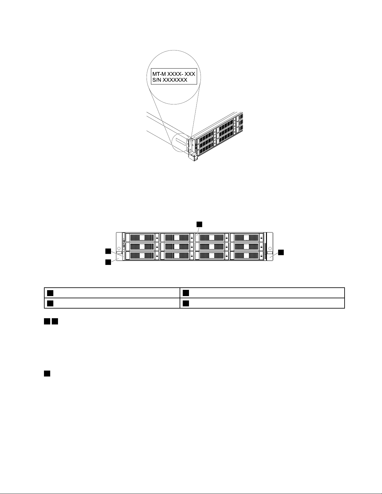
Figure1.Machinetype,model,andserialnumberlabel
1
2
3
4
0
1
2
3
4
5
6
7
8
9
10
11
Frontviewofthestorageproduct
Figure2.Frontviewofthestorageproduct
1Rackhandle(left)
33.5-inch-drivebays(0–11)4Rackhandle(right)
14Rackhandles
2Frontpanel
Ifyourstorageproductisinstalledinarackcabinet,youcanusetherackhandlestohelpyouslidethe
storageproductoutoftherackcabinet.Y oualsocanusetherackhandlesandscrewstosecurethestorage
productintherackcabinetsothatthestorageproductcannotslideout,especiallyinvibration-proneareas.
Formoreinformation,refertotheRackInstallationInstructionsthatcomeswithyourstorageproduct.
2Frontpanel
Forinformationaboutthecontrols,connectors,andstatusLEDsonthefrontpanel,see“Frontpanel”
onpage16.
Chapter3.Productoverview15
Page 30
33.5-inch-drivebays(0–11)
1
3
2
4
TheEMIintegrityandcoolingofthestorageproductareprotectedbyhavingalldrivebayscoveredor
occupied.Thenumberoftheinstalleddrivesinyourstorageproductvariesbymodel.Thevacantdrivebays
areoccupiedbydummytrays.
Whenyouinstalldrives,followtheorderofthedrivebaynumbers.
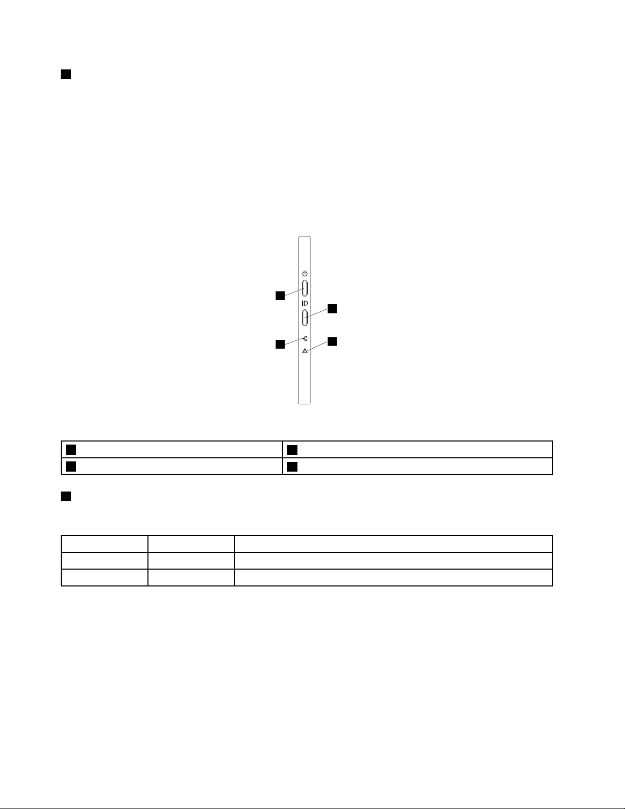
Frontpanel
Thefollowingillustrationshowsthecontrols,connectors,andLEDsonthefrontpanelofthestorageproduct.
Tolocatethefrontpanel,see“Frontviewofthestorageproduct”onpage15.
Figure3.Frontpanel
1NetworkstatusLED
3PowerbuttonwithpowerstatusLED
1NetworkstatusLED
2SystemhealthLED
4SystemIDbuttonwithIDLED
ThenetworkstatusLEDonthefrontpanelhelpsyouidentifythenetworkconnectivityandactivity.
StatusColor
Blinking
Off
Green
None
TheLANisconnectedandactive.
ThestorageproductisdisconnectedfromaLAN.
Description
16LenovoStorageN4610UserGuideandHardwareMaintenanceManual
Page 31

2SystemhealthLED
ThesystemhealthLEDprovidesbasicdiagnosticfunctionsforyourstorageproduct.Ifthesystemhealth
LEDislit,oneormoreLEDselsewhereinthestorageproductmightalsobelittodirectyoutothesourceof
theerror.See“SystemfanfaultLEDs”onpage31
.
StatusColor
Thetemperatureofthestorageproduct
reachedthenon-criticaltemperature
threshold.
Thevoltageofthestorageproductreached
thenon-criticalvoltagethreshold.
Afanhasbeendetectedtoberunningat
lowspeed.
Ahot-swapfanhasbeenremoved.1.Ensurethatthesystemfansare
On
BlinkingAmberThestorageproductisinitialized.
Off
Amber
Thepowersupplyhasacriticalerror.
Thepowercordhasbeendisconnected
fromonepowersupplyoraredundant
powersupplyhasbeenremoved.
TheTHERMTRIP#signalisasserted
becausethesystemisoverheated.
None
Thestorageproductisofforthestorage
productisonandisworkingcorrectly.
DescriptionAction
ChecktheBMCforerrorsandcheckthe
systemfans.
Replacethesystemboard.
Note:Thisproceduremustbeperformed
onlybytrainedservicepersonnelofLenovo.
SeeChapter8“Gettinginformation,help,
andservice”onpage145
Checkthesystemfans.
connectedsecurelytothesystem
board.
2.Reinstalltheremovedfanorinstalla
newfantoreplacetheremovedfan.
ChecktheBMCfordetailedinformation.
1.Ensurethatthepowersuppliesare
installedsecurelyinthestorage
product.
2.Ensurethatthepowercordsare
connectedsecurelytothepower
supplies.
3.Installanewpowersupplytoreplace
theremovedone.
ChecktheBMCforerrorsandthencheck
thesystemfans.
.
3PowerbuttonwithpowerstatusLED
Youcanpressthepowerbuttontoturnonthestorageproductwhenyoufinishsettingupthestorage
product.Y oualsocanholdthepowerbuttonforseveralsecondstoturnoffthestorageproductifyou
cannotturnoffthestorageproductfromtheoperatingsystem.SeeChapter4“Turningonandturningoffthe
storageproduct”onpage35.ThepowerstatusLEDhelpsyoutodeterminethecurrentpowerstatus.
StatusColor
OnGreen
Off
Thestorageproductison.
None
Thestorageproductisoff.
Description
Chapter3.Productoverview17
Page 32

4SystemIDbuttonwithIDLED
1
2
3 4 5 6 7 8 9 10
111213151617 14
WhenyoupresstheIDbuttononthefrontpanel,theIDLEDsonboththefrontandrearofthestorage
productarelittohelpyoulocatethestorageproductamongotherstorageproducts.Youalsocanturnon
theIDLEDsusingaremotemanagementprogramforstorageproductpresencedetection.
StatusColor
On
Off
Blue
None
Thestorageproductisidentified.
TheIDLEDisnotinuseorthestorageproductisnotidentified.
Description
Rearviewofthestorageproduct
Thistopicprovidesinformationtohelpyoulocatetheconnectorsandcomponentsontherearofyour
storageproduct.
Thefollowingillustrationshowstherearviewofthestorageproduct.
Figure4.Rearviewofthestorageproduct
1Powersupply2(availableonsomemodels)
3PCIeslot84PCIeslot7
5PCIeslot5(onrisercardassembly2)6PCIeslot6(onrisercardassembly2)
7PCIeslot48PCIeslot1(onrisercardassembly1)
9PCIeslot2(onrisercardassembly1)10PCIeslot3(onrisercardassembly1)
11AnyFabricslot12DisplayPortconnector
13Serialconnector14USB3.0connectors(2)
152.5-inch-drivebays(2)16Ethernetconnectorforsystemmanagement(RJ-45)
17SystemIDLED
2Powersupply1
1Powersupply2(availableonsomemodels)
2Powersupply1
Thehot-swapredundantpowersupplieshelpyouavoidsignificantinterruptiontotheoperationofthe
systemwhenapowersupplyfails.YoucanpurchaseapowersupplyoptionfromLenovoandinstallthe
powersupplytoprovidepowerredundancywithoutturningoffthestorageproduct.
Oneachpowersupply,therearethreestatusLEDsnearthepowercordconnector.Forinformationabout
thestatusLEDs,see“PowersupplystatusLEDs”onpage33
18LenovoStorageN4610UserGuideandHardwareMaintenanceManual
.
Page 33

347PCIecardslotsonthesystemboard
Slot
3PCIeslot8
4PCIeslot7
7PCIeslot4
56PCIecardslotsontherisercardassembly2
Slot
5PCIeslot5
6PCIeslot6
8910PCIecardslotsontherisercardassembly1
Slot
8PCIeslot1
9PCIeslot2
10PCIeslot3
11AnyFabricslot
PhysicallinkwidthNegotiablelinkwidth
x16x8,x4,x2,x1
x16x8,x4,x2,x1
x16x8,x4,x2,x1
PhysicallinkwidthNegotiablelinkwidth
x16x8,x4,x2,x1
x16x8,x4,x2,x1
PhysicallinkwidthNegotiablelinkwidth
x16x8,x4,x2,x1
x16x8,x4,x2,x1
x16x8,x4,x2,x1
UsedtoinstallanAnyFabricadapter(alsocalledmezzanineadapter).
Supportedcardlengthandheight
Low-profilecard
Low-profilecard
Low-profilecard
Supportedcardlengthandheight
Half-length,full-heightcard
Half-length,full-heightcard
Supportedcardlengthandheight
Half-length,full-heightcard
Half-length,full-heightcard
Half-length,full-heightcard
12DisplayPortconnector
Usedtoattachahigh-performancemonitor,adirect-drivemonitor,orotherdevicesthatuseaDisplayPort
connector.
13Serialconnector
Usedtoattachadevicethatusesa9-pinserialconnector.
14USB3.0connectors(2)
UsedtoattachadevicethatrequiresaUSB2.0or3.0connection,suchasakeyboard,amouse,ascanner,
aprinter,orapersonaldigitalassistant(PDA).
152.5-inch-drivebays(2)
Usedtoinstalltwo2.5-inchdrives.
Chapter3.Productoverview19
Page 34

16Ethernetconnectorforsystemmanagement(RJ-45)
UsedtoattachanEthernetcableforaLAN.TheEthernetconnectorhastwostatusLEDstohelpyouidentify
theEthernetconnectivity,activity,andconnectionspeed.
Figure5.EthernetstatusLEDs
EthernetstatusLED
1Left:dataspeed
2Right:linkandactivity
17SystemIDLED
ColorStatus
Amber
GreenOn
None
GreenOn
None
Green
On
Off
Off
BlinkingTheLANisconnectedandactive.
Theconnectionspeedis1000Mbps.
Theconnectionspeedis100Mbps.
Theconnectionspeedis10Mbps.
ThestorageproductisconnectedtoaLAN.
Thestorageproductisdisconnectedfroma
LAN.
Description
WhenyoupresstheIDbuttononthefrontpanel,theIDLEDsonboththefrontandrearofthestorage
productarelittohelpyoulocatethestorageproductamongotherstorageproducts.Youalsocanturnon
theIDLEDsusingaremotemanagementprogramforstorageproductpresencedetection.
StatusColor
On
Off
Blue
None
Thestorageproductisidentified.
TheIDLEDisnotinuseorthestorageproductisnotidentified.
Description
Storageproductcomponents
Thistopicprovidesinformationtohelpyoulocatethecomponentsofyourstorageproduct.Formore
informationaboutmajorcomponents,seetherelatedtopicsin“Locations”onpage14.
Toremovethestorageproductcoverandgainaccesstotheinsideofthestorageproduct,see“Removing
thecover”onpage51.
20LenovoStorageN4610UserGuideandHardwareMaintenanceManual
Page 35

Note:Dependingonthemodel,yourstorageproductmightlookslightlydifferentfromtheillustrationin
4
3
5
25
24
23
22
11
12
16
17
18
13
14
15
26
20
21
19
1
2
6
8
9
7
10
thistopic.
Figure6.Storageproductcomponents
1Rackhandle(right)
3Rackhandle(left)
5AnyRAIDadapter6Frontbackplane
7Systemfancage8Systemfan
9Systemboard10CPU1DIMMs(varybymodel)
11Heatsink
13AnyFabricadapter(availableonsomemodels)14Coolingshroud
15ThinkServerRAIDSuperCapacitorModule(available
23.5-inch-drivearea
4Frontpanelboard
12Coin-cellbattery
16Risercardassembly
onsomemodels)
17PCIecard(availableonsomemodels)18Intrusionswitch(availableonsomemodels)
19Rearbackplane/cageassembly
21Powersupply2(availableonsomemodels)
20Powersupply1
22Powerdistributionboard
Chapter3.Productoverview21
Page 36

23CPU2DIMMs(varybymodel)24CPU2DIMMs(varybymodel)
25CPU1DIMMs(varybymodel)26Cover
CRUsarepartsthatcanbeupgradedorreplacedbythecustomer.IfaCRUisdeterminedtobedefective
duringthewarrantyperiod,areplacementCRUwillbeprovidedtothecustomer.Customersareresponsible
forinstallingtheself-serviceCRUsforthisproduct.Customersalsocaninstalloptional-serviceCRUs,which
mightrequiresometechnicalskillsortools,orrequestthatatechnicianinstalltheoptional-serviceCRU
underthetermsoftheapplicablewarrantyservicetypeforyourcountryorregion.
Non-CRUsmustbereplacedonlybytrainedservicetechnicians.
ThefollowingtableliststhemajorFRUsinyourstorageproductandtheCRUidentificationinformation.For
acompletelistingofFRUinformation,suchasFRUpartnumbersandsupportedstorageproductmodels,
goto:
http://www.lenovo.com/serviceparts-lookup
Notes:
•BeforeservicingaLenovoproduct,ensurethatyoureadandunderstand“Safetyinformation”onpageiii
•UseonlypartsprovidedbyLenovo.
*Availableonsomemodels
FRUdescription
AnyFabricadapter*YesNo
AnyRAIDadapterNoYes
Coin-cellbattery
Coolingshroud
FrontbackplaneNoYes
FrontpanelboardYesNo
HeatsinkYesNo
Hot-swapstoragedrive*YesNo
Hot-swapredundantpowersupplyYesNo
Intrusionswitch*YesNo
MemorymoduleYesNo
MicroprocessorNoYes
PCIecard*
PowercordYesNo
PowerdistributionboardNoNo
RearbackplaneYesNo
Rearbackplane/cageassembly
RisercardYesNo
Systemboard
Systemfan
Systemfancage
Self-serviceCRUOptional-serviceCRU
YesNo
YesNo
YesNo
YesNo
NoNo
YesNo
YesNo
.
22LenovoStorageN4610UserGuideandHardwareMaintenanceManual
Page 37

FRUdescription
ThinkServerRAIDSuperCapacitorModule*
ThinkServerSystemManagerPremiummodule*
Self-serviceCRUOptional-serviceCRU
YesNo
YesNo
AnyRAIDadapterandHostBusAdapter
YourstorageproductsupportstheLenovoThinkServerRAID720ixAnyRAIDAdapter.TheAnyRAIDadapter
providesadvancedSATA/SAShardwareRAIDfunctions.YourstorageproductalsosupportstheHost
BusAdapter(HBA).YoucanuseaHostBusAdaptertoconnectyourstorageproducttoexternalstorage
devices,suchasastoragearray.
YoucanpurchaseasupportedAnyRAIDadapterandHostBusAdapterfromLenovoandinstallitintothe
storageproduct.Foralistofstorageproductoptions,goto:
http://shop.lenovo.com/us/en/servers/network-storage/
Note:Theoptionkitisdesignedfordifferenttypesofstorageproductsandmightcontainadditionalcables
thatarenotrequiredforyourstorageproduct.
Chapter3.Productoverview23
Page 38

ThefollowingillustrationshowstheconnectorsontheLenovoThinkServerRAID720ixAnyRAIDAdapter.
Note:Dependingontheconfiguration,theAnyRAIDadapterinstalledinyourstorageproductmightlook
slightlydifferentfromtheillustrationinthistopic.
Figure7.LenovoThinkServerRAID720ixAnyRAIDAdapter
1SA T Aconnector
UsedtoconnecttheSATAsignalcablefromtherearbackplaneforuptotwo2.5-inchdrives.
2ThinkServerRAIDSuperCapacitorModuleconnector
UsedtoconnecttotheThinkServerRAIDSuperCapacitorModule.See“Storageproductcomponents”
onpage20.
3PCIE0connector
4PCIE1connector
UsedtoconnecttotheAnyRAIDconnector0–1onthesystemboard.See“Systemboardcomponents”
onpage26.
Hot-swap-drivebackplane
Yourstorageproductcomeswiththefollowingdrivebayandbackplaneconfigurations:
•Inthefront:
DrivebaysizeDrivebayquantityBackplanequantityDrivetype
3.5-inch121
Hot-swap,SATAorSAS
3.5-inchharddiskdriveor
2.5-inchsolid-statedrive
24LenovoStorageN4610UserGuideandHardwareMaintenanceManual
Page 39

•Intherear:
0 1 2 3 4 5 6 7 8
9
10 11
12 13
1415
DrivebaysizeDrivebayquantityBackplanequantityDrivetype
2.5-inch21
Tolocatethebackplanes,see“Storageproductcomponents”onpage20.
Frontbackplane
Thefollowingillustrationsshowtheslotsandconnectorsonthefrontbackplane.
Figure8.Frontviewofthefrontbackplane
Hot-swap,SATA
Harddiskdriveorsolid-state
drive
Figure9.Rearviewofthefrontbackplane
0–11Slot0–slot11
Usedtoconnect3.5-inchdrives.
1210-pinpowerconnector0
1310-pinpowerconnector1
Usedtoconnecttothe10-pinbackplanepowerconnectorsonthepowerdistributionboardtoprovide
powertothebackplane.
14AnyRAIDadapterslot0
15AnyRAIDadapterslot1
UsedtoconnectanAnyRAIDadapter.
Chapter3.Productoverview25
Page 40

Rearbackplane
0 1
2 3 4 5
6
Thefollowingillustrationsshowtheslotsandconnectorsontherearbackplane.
Figure10.Frontviewoftherearbackplane
Figure11.Rearviewoftherearbackplane
0Slot0
1Slot1
Usedtoconnect2.5-inchdrives.
2Drivesidebandsignalsconnector
4Driveconnector0
6Driveconnector1
UsedtoconnecttotheSATAconnectorontheLenovoThinkServerRAID720ixAnyRAIDAdapter.
34-pinpowerconnector
Usedtoconnecttotherear-backplanepowerconnectoronthesystemboard.
5Rear-backplanesignalconnector
Usedtoconnecttotherear-backplanesignalconnectoronthesystemboard.
Systemboardcomponents
Thefollowingillustrationshowsthecomponentlocationsonthesystemboard.
26LenovoStorageN4610UserGuideandHardwareMaintenanceManual
Page 41

10
11
1213
14
15
16
17
18
23
25
27
26
24
19
20
21
22
1 2
3
4
5
6
7
8
9
Figure12.Systemboardcomponents
1AnyRAIDconnector0-12Frontpanelconnector1
3Coin-cellbattery
5Risercardassembly1slot
7TSMPremiumconnector
9Risercardassembly2slot
11PCIeslot8
13Front-backplanepowerconnector14Intrusionswitchconnector
15Power-distribution-boardconnector
17Microprocessor2memoryslots(6)18Systemfan5connector
19Microprocessor2socket
21Microprocessor2memoryslots(6)22Systemfan3connector
23Microprocessor1memoryslots(6)24Systemfan2connector
25Microprocessor1socket
27Microprocessor1memoryslots(6)
1AnyRAIDconnector0-1
4AnyFabricconnector
6PCIeslot4
8Rear-backplanesignalconnector
10PCIeslot7
12Rear-backplanepowerconnector
16Systemfan6connector
20Systemfan4connector
26Systemfan1connector
UsedtoconnecttothePCIeconnectorsontheAnyRAIDadapter.
2Frontpanelconnector1
Usedtoconnecttothefrontpanelboard.
3Coin-cellbattery
Yourstorageproducthasaspecialtypeofmemorythatmaintainsthedate,time,andconfiguration
informationforbuilt-infeatures.Thecoin-cellbatterykeepstheinformationactivewhenyouturnoffthe
storageproduct.
Chapter3.Productoverview27
Page 42

4AnyFabricconnector
UsedtoconnecttheAnyFabricadapter.
5Risercardassembly1slot
Usedtoinstalltherisercardassembly1.
6PCIeslot4
10PCIeslot7
11PCIeslot8
UsedtoinstallasupportedPCIecard.ForinformationaboutsupportedPCIecards,see“Rearviewofthe
storageproduct”onpage18.
7TSMPremiumconnector
UsedtoconnectaTSMPremiummoduletoenableadvancedremotemanagementfunctionsonyour
storageproduct.
8Rear-backplanesignalconnector
Usedtoconnectthesignalcablefromeitheroftherearbackplaneforuptotwo2.5-inchdrives.
9Risercardassembly2slot
Usedtoinstalltherisercardassembly2.
12Rear-backplanepowerconnector
Usedtoconnecttothe4-pinpowerconnectorontherearbackplane.
13Front-backplanepowerconnector
Usedtoconnecttothe10-pinpowerconnectoronthefrontbackplane.
14Intrusionswitchconnector
Usedtoconnecttoanintrusionswitch.
15Power-distribution-boardconnector
Usedtoconnectthepowerdistributionboard.
161820222426Systemfanconnector
Usedtoconnectasystemfan.
17212327Memoryslots
Thereare24memoryslotsonthesystemboard.Fordetailedinformation,see“Memorymoduleinstallation
rules”onpage61.
28LenovoStorageN4610UserGuideandHardwareMaintenanceManual
Page 43

19Microprocessor2socket
1
3
4
2
1
2
2 1
1 2
25Microprocessor1socket
Ifthestorageproducthastwomicroprocessors,eachofthemicroprocessorissecuredinthemicroprocessor
socketonthesystemboardandaheatsinkisinstalledabovethemicroprocessortoprovidecooling.Ifthe
storageproducthasonlyonemicroprocessor,themicroprocessorsocket2isprotectedbyamicroprocessor
socketcover.
Systemboardjumpers
Thefollowingillustrationshowsthejumpersonthesystemboardofyourstorageproduct.
Figure13.Systemboardjumpers
1BIOSdefaultsettingsjumper2Clearpasswordjumper
3BIOSrecoveryjumper
4Jumpercapstorage
Attention:Tosetthejumpers,removethestorageproductcoverandgainaccesstothesystemboard
first.Donotopenyourstorageproductorattemptanyrepairbeforereadingandunderstanding“Safety
information”onpageiii
1BIOSdefaultsettingsjumper
and“Guidelines”onpage49.
UsedtoturntheBIOSsettingsintothefactorydefaultsettings.
ToturntheBIOSsettingsintothefactory-defaultsettings,dothefollowing:
1.Removeallexternalmediafromthedrivesandturnoffallattacheddevicesandthestorageproduct.
Then,disconnectallpowercordsfromelectricaloutletsanddisconnectallcablesthatareconnectedto
thestorageproduct.
2.Prepareyourstorageproduct.See“Removingorextendingthestorageproductfromtherackcabinet”
onpage51
3.Removethestorageproductcover.See“Removingthecover”onpage51.
4.LocatetheBIOSdefaultsettingsjumper1onthesystemboard.Then,removeanypartsand
.
disconnectanycablesthatmightimpedeyouraccesstothejumper.
Chapter3.Productoverview29
Page 44

Note:Donotremovethememorymodulesormicroprocessors.
5.Removethejumpercapfromthejumpercapstorage4.
6.NotetheorientationofthejumpercapandtheninstallthejumpercapontheBIOSdefaultsettings
jumper.
7.Reinstallanypartsandreconnectanycables.Then,reinstallthestorageproductcover.See
“Completingthepartsreplacement”onpage135.
8.Connectthestorageproducttoanacpowersourceandwaitforseveralminutes.Then,turnonthe
storageproduct.TheBIOSsettingsturnintothefactory-defaultsettings.
9.Repeatstep1throughstep3.
10.Movethejumpercapbacktothejumpercapstorage4.
11.Reinstallanypartsandreconnectanycables.Then,reinstallthestorageproductcover.See
“Completingthepartsreplacement”onpage135.
12.Connectthestorageproducttoanacpowersourceandturnonthestorageproduct.
2Clearpasswordjumper
Usedtoeraseforgottenpasswords,suchastheBIOSpasswords.
Toclearpasswords,dothefollowing:
1.Removeallexternalmediafromthedrivesandturnoffallattacheddevicesandthestorageproduct.
Then,disconnectallpowercordsfromelectricaloutletsanddisconnectallcablesthatareconnectedto
thestorageproduct.
2.Prepareyourstorageproduct.See“Removingorextendingthestorageproductfromtherackcabinet”
onpage51
.
3.Removethestorageproductcover.See“Removingthecover”onpage51.
4.Locatetheclearpasswordjumper2onthesystemboard.Then,removeanypartsanddisconnectany
cablesthatmightimpedeyouraccesstothejumper.
Note:Donotremovethememorymodulesormicroprocessors.
5.Removethejumpercapfromthejumpercapstorage4.
6.Notetheorientationofthejumpercapandtheninstallthejumpercapontheclearpasswordjumper.
7.Reinstallanypartsandreconnectanycables.Then,reinstallthestorageproductcover.See
“Completingthepartsreplacement”onpage135.
8.Connectthestorageproducttoanacpowersourceandwaitforseveralminutes.Then,turnonthe
storageproduct.TheBIOSpasswordsareerased,includingtheadministratorpasswordanduser
password.
9.Repeatstep1throughstep3.
10.Movethejumpercapbacktothejumpercapstorage4.
11.Reinstallanypartsandreconnectanycables.Then,reinstallthestorageproductcover.See
“Completingthepartsreplacement”onpage135.
12.Connectthestorageproducttoanacpowersourceandturnonthestorageproduct.
13.Tosetnewpasswords,see“Usingpasswords”onpage40.
30LenovoStorageN4610UserGuideandHardwareMaintenanceManual
Page 45

3BIOSrecoveryjumper
1
1
UsedtorecovertheBIOSifthepowertoyourstorageproductisinterruptedwhiletheBIOSisbeingupdated
andyourstorageproductcannotstartcorrectly.
TorecovertheBIOS,see“RecoveringfromaBIOSupdatefailure”onpage43.
4Jumpercapstorage
Usedtostorethejumpercap.Ajumpercapisencasedonthepinsbydefault.
SystemfanfaultLEDs
ThefollowingillustrationshowsthesystemfanfaultLEDs1onthesystemboard.
Figure14.SystemfanfaultLEDs
YoucanviewthesystemfanfaultLEDs1fromthetopofthesystemfans.WhenasystemfanfaultLEDis
lit,itindicatesthatthecorrespondingsystemfanisoperatingslowlyorhasfailed.Tosolvetheproblem,
reinstallorreplacethesystemfan.See“Installingorreplacingasystemfan”onpage56.Ifitisasystem
boardproblem,contacttheLenovoCustomerSupportCenter.
Figure15.ViewingthesystemfanfaultLEDsfromthetopofthesystemfans
Chapter3.Productoverview31
Page 46

Hot-swap-drivestatusLEDs
Eachhot-swapdrivehastwostatusLEDsonthefront.
h
Figure16.Hot-swap-drivestatusLEDs
1DriveactivityLED2DrivestatusLEDDescription
OffOff
On,greenOff
Blinking,green
On,greenBlinkingrapidly(aboutfourflashes
On,greenOn,amber
Blinking,green
Off
persecond),amber
Blinkingslowly(aboutoneflashper
second),amber
Thedrivehasfailedorisnotpresent.
Thedriveispresentbutnotinuse.
Thedriveisactiveanddataisbeing
transferred.
TheRAIDcontrollerisidentifyingthe
drive.
TheRAIDarrayhasfailedandcannot
berecovered.Youneedtorecreatea
newarray.
Thedriveisbeingrebuilt.
32LenovoStorageN4610UserGuideandHardwareMaintenanceManual
Page 47

PowersupplystatusLEDs
1
2
3
Eachhot-swappowersupplyhasthreestatusLEDs.
Figure17.PowersupplystatusLEDs
LED
1InputstatusLED
2Outputstatus
LED
3FaultLED
Status
Off
On,green
Off
Blinking,green(aboutone
flasheverytwoseconds)
Blinking,green(abouttwo
flasheseachsecond)
On,green
Off
On,amber
DescriptionAction
Thepowersupplyis
disconnectedfromtheac
powersource.
Thepowersupplyisconnected
totheacpowersource.
Thestorageproductisoffor
thepowersupplyisnotworking
normally.
Thepowersupplyisincold
redundancyactivemode.
Thepowersupplyisincold
redundancysleepmode.
Thestorageproductisonand
thepowersupplyisworking
normally.
Thepowersupplyisworking
normally.
Thepowersupplyhasfailed.
Noactionisneeded.
Noactionisneeded.
Replacethepowersupply.
See“Installingorreplacinga
hot-swapredundantpower
supply”onpage93
Noactionisneeded.
Noactionisneeded.
Noactionisneeded.
Noactionisneeded.
Replacethepowersupply.
See“Installingorreplacinga
hot-swapredundantpower
supply”onpage93
.
.
Connectingcables
Toconnectthesignalcablesfromtheinstalledhardwarecomponents,refertotherelatedinformation
inthefollowingtopics:
•“Systemboardcomponents”onpage26
•“AnyRAIDadapterandHostBusAdapter”onpage23
•“Hot-swap-drivebackplane”onpage24
Chapter3.Productoverview33
Page 48

34LenovoStorageN4610UserGuideandHardwareMaintenanceManual
Page 49

Chapter4.Turningonandturningoffthestorageproduct
Thischapterprovidesinformationaboutturningonandturningoffthestorageproduct.
Turningonthestorageproduct
Thestorageproductcanbeturnedoninoneofthefollowingways:
•Afteryoufinishunpackingandsettingupthestorageproduct,connectittoanacpowersource.Press
thepowerbuttononthefrontpaneltoturnonthestorageproduct.See“Frontpanel”onpage16
storageproductneedsabout30secondsfortheThinkServerSystemManager(TSM,alsoknownas
BMC)toinitializewheneveryouconnectthestorageproducttoanacpowersource.Ifyoupressthe
powerbuttononthefrontpanelduringthisperiod,thestorageproductwillnotstartimmediately;itwill
startaftertheTSMinitializationfinishes.
•WhentheWakeonLANfeatureisenabledonthestorageproductthatisconnectedtoanacpower
sourceandaLAN,anetworkadministratorcanremotelyturnonorwakeupthestorageproductfroma
managementconsoleusingremotenetworkmanagementsoftware.
•YoualsocanusetherelatedTSMfeaturetoremotelyturnonthestorageproductthroughthe
managementLAN.
Turningoffthestorageproduct
CAUTION:
Thepowercontrolbuttononthedeviceandthepowerbuttononthepowersupplydonotturnoff
theelectricalcurrentsuppliedtothedevice.Thedevicealsomighthavemorethanonepower
cord.T oremoveallelectricalcurrentfromthedevice,ensurethatallpowercordsaredisconnected
fromthepowersource.
.The
Thestorageproductcanbeturnedoffinoneofthefollowingways:
•Turnoffthestorageproductfromtheoperatingsystemifyouroperatingsystemsupportsthisfeature.
Afteranorderlyshutdownoftheoperatingsystem,thestorageproductwillturnoffautomatically.For
instructionsonhowtoshutdownyourspecificoperatingsystem,refertotherelateddocumentationor
helpsystemfortheoperatingsystem.
•Pressthepowerbuttononthefrontpaneltostartanorderlyshutdownoftheoperatingsystemandturn
offthestorageproduct,ifyouroperatingsystemsupportsthisfeature.
•Ifyourstorageproductstopsrespondingandyoucannotturnitoff,pressandholdthepowerbuttonon
thefrontpanelforfoursecondsormore.Ifyoustillcannotturnoffthestorageproduct,disconnectall
powercordsfromthestorageproduct.
•IfthestorageproductisconnectedtoaLAN,anetworkadministratorcanremotelyturnoffthestorage
productfromamanagementconsoleusingremotenetworkmanagementsoftware.
•YoualsocanusetherelatedTSMfeaturetoremotelyturnoffthestorageproductthroughthe
managementLAN.
•Thestorageproductmightbeturnedoffasanautomaticresponsetoacriticalsystemfailure.
Notes:
©CopyrightLenovo2015
35
Page 50

•Whenyouturnoffthestorageproductandleaveitconnectedtoanacpowersource,thestorageproduct
alsocanrespondtoaremoterequesttoturnonthestorageproduct.Toremoveallpowerfromthe
storageproduct,youmustdisconnectthestorageproductfromtheacpowersource.
•Forinformationaboutyourspecificoperatingsystem,refertotherelateddocumentationorhelpsystem
fortheoperatingsystem.
36LenovoStorageN4610UserGuideandHardwareMaintenanceManual
Page 51

Chapter5.Configuringthestorageproduct
Thischapterprovidesthefollowinginformationtohelpyouconfigurethestorageproduct:
•“UsingtheSetupUtilityprogram”onpage37
•“ConfiguringRAID”onpage44
•“Updatingthefirmware”onpage46
UsingtheSetupUtilityprogram
TheSetupUtilityprogramispartofthestorageproductfirmware.Y oucanusetheSetupUtilityprogram
toviewandchangetheconfigurationsettingsofyourstorageproduct,regardlessofwhichoperating
systemyouareusing.However,theoperatingsystemsettingsmightoverrideanysimilarsettingsinthe
SetupUtilityprogram.
StartingtheSetupUtilityprogram
TostarttheSetupUtilityprogram,dothefollowing:
1.Connectthestorageproducttoanacpowersourceandpressthepowerbuttononthefrontpanelto
turnonthestorageproduct.See“T urningonthestorageproduct”onpage35.
2.PresstheF1keyassoonasyouseethescreen.Then,waitforseveralseconds,andtheSetupUtility
programopens.Ifyouhavesetapassword,typethecorrectpasswordtoentertheSetupUtility
program.Forpasswordinformation,see“Usingpasswords”onpage40.
ViewinginformationintheSetupUtilityprogram
TheSetupUtilityprogrammenulistsvariousitemsaboutthesystemconfiguration.Selectadesireditem
toviewinformationorchangesettings.
WhenworkingwiththeSetupUtilityprogram,youmustusethekeyboard.Thekeysusedtoperformvarious
tasksaredisplayedontherightbottompaneofeachscreen.Y oualsocanpresstheF1keyforgeneralhelp
aboutthekeys.Formostitems,thecorrespondinghelpmessageisdisplayedontherighttoppaneofthe
screenwhentheitemisselected.Iftheitemhassubmenus,youcandisplaythesubmenusbypressingEnter.
SetupUtilityprograminterface
DependingontheBIOSversionofyourstorageproduct,somemenuoriteminformationmightdifferslightly
fromtheinformationinthistopic.
Notes:
•Thedefaultsettingsalreadyareoptimizedforyou.Usethedefaultvalueforanyitemyouarenotfamiliar
with.Donotchangethevalueofunfamiliaritemstoavoidunexpectedproblems.Ifyouconsiderchanging
thestorageproductconfiguration,proceedwithextremecaution.Settingtheconfigurationincorrectly
mightcauseunexpectedresults.IfyoucannotturnonthestorageproductbecauseofincorrectBIOS
settings,usetheBIOSdefaultsettingsjumpertorestoretheBIOSsettingstothefactorydefaultsettings.
See“Systemboardjumpers”onpage29
•Ifyouhavechangedanyhardwareinthestorageproduct,youmightneedtoupgradetheBIOSand
theTSMfirmware.
.
©CopyrightLenovo2015
37
Page 52

TheSetupUtilityprogrammaininterfaceconsistsofthefollowingmenus:
•“SystemInformationmenu”onpage38
•“AdvancedSettingsmenu”onpage38
•“SystemSecuritymenu”onpage39
•“TSMSettingsmenu”onpage39
•“BootManagermenu”onpage39
•“Save&Exitmenu”onpage39
LenovoprovidestheBIOSupdateutilityontheLenovoSupportWebsite.YoucandownloadtheBIOS
updateutilitytoupdatetheBIOS.See“UpdatingorrecoveringtheBIOS”onpage42
IfthepowertoyourstorageproductisinterruptedwhiletheBIOSisbeingupdatedandyourstorageproduct
cannotstartcorrectly,theBIOSwillrecovertothepreviousversionautomatically.Therecoveryprocess
lastsabout20minutes.YoualsocanusetheBIOSrecoveryjumpertorecoverfromaBIOSupdatefailure.
See“Systemboardjumpers”onpage29.
.
SystemInformationmenu
AfterenteringtheSetupUtilityprogram,youcanseetheSystemInformationmenu.Themenulistsbasic
informationaboutyourstorageproduct,suchastheBIOS,microprocessortype,memory,andsystem
dateandtime.
TosetthesystemdateandtimeontheSystemInformationmenu,see“Settingthesystemdateand
time”onpage40
.
AdvancedSettingsmenu
YoucanvieworchangevariousstorageproductcomponentsettingsontheAdvancedSettingsmenuinthe
SetupUtilityprogram.TheAdvancedSettingsmenucontainsvariousconfigurationsubmenusanditems.
Oneachsubmenu,pressEntertoshowselectableoptionsandselectadesiredoptionbyusingtheupand
downarrowkeysortypedesiredvaluesfromthekeyboard.Someitemsaredisplayedonthemenuonlyif
thestorageproductsupportsthecorrespondingfeatures.
Notes:
•Enabledmeansthatthefunctionisconfigured.
•Disabledmeansthatthefunctionisnotconfigured.
TheAdvancedSettingsmenucontainsthefollowingsubmenus.Formoreinformation,enterthe
correspondingsubmenuandrefertotheinstructionsonthescreen.
•ProcessorSettings:Viewinformationabouttheinstalledmicroprocessorsandsetmicroprocessor
configurationparameters.
•MemorySettings:Viewinformationabouttheinstalledmemorymodulesandsetmemoryconfiguration
parameters.
•AdvancedPowerSettings:Viewandsetpowerandperformanceparameters.
•PCI/PCIESettings:ViewandsetPCIorPCIeconfigurationparameters.
•SATASettings:SetonboardSATAparameters.
•USBSettings:ViewandsetUSBconfigurationparameters,suchasenablingordisablingUSBdevices.
•SerialSettings:Viewandsetconfigurationparametersfortheserialconnector.
•WakeupSettings:Viewandconfigurethewakeuptimingandsetthepowerstateafterapowerfailure.
38LenovoStorageN4610UserGuideandHardwareMaintenanceManual
Page 53

•MiscellaneousSettings:Viewandconfiguresomemiscellaneousitems,suchastheNumLockkeyon
thekeyboardandthebootstatuscode.
SystemSecuritymenu
YoucansetpasswordsontheSystemSecuritymenuintheSetupUtilityprogram.Foreachmenuitem,
pressEntertoshowselectableoptionsandselectadesiredoptionbyusingtheupanddownarrowkeysor
typedesiredvaluesfromthekeyboard.Someitemsaredisplayedonthemenuonlyifthestorageproduct
supportsthecorrespondingfeatures.
Notes:
•Enabledmeansthatthefunctionisconfigured.
•Disabledmeansthatthefunctionisnotconfigured.
TheSystemSecuritymenucontainsthefollowingitems:
•AdministratorPassword:Setanadministratorpasswordtoprotectagainstunauthorizedaccesstoyour
storageproduct.See“Usingpasswords”onpage40
•UserPassword:Setauserpasswordtoprotectagainstunauthorizedaccesstoyourstorageproduct.
See“Usingpasswords”onpage40.
•SecureBoot:Setsecurebootparameters.
.
TSMSettingsmenu
YoucanvieworchangeeventlogandBMCsettingsontheTSMSettingsmenuintheSetupUtilityprogram.
Oneachsubmenu,pressEntertoviewtheinformationorshowselectableoptionsandselectadesired
optionbyusingtheupanddownarrowkeys.Someitemsaredisplayedonthemenuonlyifthestorage
productsupportsthecorrespondingfeatures.
TheTSMSettingsmenucontainsthefollowingsubmenus.Formoreinformation,enterthecorresponding
submenuandrefertotheinstructionsonthescreen.
•TSMNetworkSettings:SetBMCmanagementnetworkconfigurationparameters.
•UserAccountSettings:SetBMCuseraccountparameters.
BootManagermenu
TheBootManagermenuintheSetupUtilityprogramlistsallthebootabledevicesinstalledinyourstorage
productandthelisteditemsvarydependingonyourstorageproductconfiguration.
TheBootSequencesubmenuintheBootManagermenuprovidesaninterfacetohelpyouvieworchange
thestorageproductstartupoptions,includingthestartupsequenceandbootpriorityforvariousdevices.
Changesinthestartupoptionstakeeffectwhenthestorageproductrestarts.Thestartupsequencespecifies
theorderinwhichthestorageproductchecksdevicestofindabootrecord.Thestorageproductstartsfrom
thefirstbootrecordthatitfinds.Forexample,youcandefineastartupsequencethatchecksadiscinthe
opticaldrive,thencheckstheinternalstoragedrive,andthenchecksanetworkdevice.Forinformationabout
settingthestartupsequenceorselectingastartupdevice,see“Selectingastartupdevice”onpage41.
Save&Exitmenu
AfteryoufinishviewingorchangingsettingsintheSetupUtilityprogram,youcanchooseadesired
actionfromtheSave&Exitmenutosavechanges,discardchanges,orloaddefaultvalues,andexitthe
program.PressEntertoselecttheitemontheSave&Exitmenu,andthenselectYeswhenpromptedto
confirmtheaction.ForinformationaboutexitingtheSetupUtilityprogram,see“ExitingtheSetupUtility
program”onpage42
.
TheSave&Exitmenucontainsthefollowingitems:
Chapter5.Configuringthestorageproduct39
Page 54

•SaveChangesandReset:SavechangesandthencontinuewithfurtherconfigurationintheSetup
Utilityprogram.
•DiscardChangesandExit:Discardchanges,loadpreviousvalues,andthenexittheSetupUtility
program.
•LoadOptimizedDefaults:Returntotheoptimizeddefaultsettings.
•SaveasUserDefaults:Savethecurrentsettingsasuserdefaultvalues.
•RestoreUserDefaults:Restoretheuserdefaultvaluesforalltheitems.
•PureUEFIOSOptimizedDefaults:EnableordisableoptimizeddefaultsettingsforthepureUEFI
operatingsystem.
Settingthesystemdateandtime
TosetthesystemdateandtimeintheSetupUtilityprogram,dothefollowing:
1.StarttheSetupUtilityprogram.See“StartingtheSetupUtilityprogram”onpage37.
2.OntheSystemInformationmenu,selectSystemDateorSystemTime.
3.UsetheTabkeytoswitchbetweendataelementsandtypethenumbersfromthekeyboardtosetthe
systemdateandtime.
4.PressF10tosavesettingsandexittheSetupUtilityprogram.
Usingpasswords
ByusingtheSetupUtilityprogram,youcansetapasswordtopreventunauthorizedaccesstoyour
storageproduct.
Youdonothavetosetapasswordtouseyourstorageproduct.However,usingapasswordimproves
computingsecurity.Ifyoudecidetosetapassword,readthefollowingtopics.
SetupUtilityprogrampasswordtypes
ThefollowingtypesofpasswordsareavailableintheSetupUtilityprogram:
•Administratorpassword
Settinganadministratorpassworddetersunauthorizedusersfromchangingconfigurationsettings.Ifyou
areresponsibleformaintainingtheconfigurationsettingsofseveralcomputers,youmightwanttoset
anadministratorpassword.Whenanadministratorpasswordisset,youarepromptedtotypeavalid
passwordeachtimeyoutrytoaccesstheSetupUtilityprogram.TheSetupUtilityprogramcannot
beaccesseduntilavalidpasswordistypedin.
•Userpassword
Whenauserpasswordisset,youarepromptedtotypeavalidpasswordeachtimethestorageproduct
turnson.Youcannotlogintoanyoperatingsystemuntilavalidpasswordistypedin.
Note:Ifboththeadministratorpasswordanduserpasswordareset,youcantypeeitherpasswordtousethe
storageproduct.However,youmustuseyouradministratorpasswordtochangeanyconfigurationsettings.
Passwordconsiderations
Forsecurityreasons,itisrecommendedtouseastrongpasswordthatcannotbeeasilycompromised.
Notes:
•TheSetupUtilityprogrampasswordsarenotcasesensitive.
•ThestorageproductsupportsSetupUtilityprogrampasswordsthatconsistofthreeto32characters.
40LenovoStorageN4610UserGuideandHardwareMaintenanceManual
Page 55

Tosetastrongpassword,usethefollowingguidelines:
•Haveatleasteightcharactersinlength
•Containatleastonealphabeticcharacterandonenumericcharacter
•Notbeyournameoryourusername
•Notbeacommonwordoracommonname
•Besignificantlydifferentfromyourpreviouspasswords
Besidesthealphabeticcharacters(a–z)andnumericcharacters(0–9),thestorageproductalsosupports
characterstypedusingspecialkeysonthekeyboardforapassword.Refertothehelpmessageonthe
screenwhensettingapasswordtodeterminethevalidspecialcharacters.
Setting,changing,ordeletingapassword
Thistopicprovidesinstructionsonhowtoset,change,ordeleteapasswordintheSetupUtilityprogram.
Toset,change,ordeleteapasswordintheSetupUtilityprogram,dothefollowing:
1.StarttheSetupUtilityprogram.See“StartingtheSetupUtilityprogram”onpage37.
2.OntheSystemSecuritymenu,selectAdministratorPasswordtosetanadministratorpasswordor
selectUserPasswordtosetauserpassword.
3.See“Passwordconsiderations”onpage40.Then,followtheinstructionsonthescreentosetor
changeapassword.
4.Ifyouwanttodeleteapassword,typeyourcurrentpassword.PressEnterwhenyouareprompted
totypeanewpassword.Then,pressEntertoconfirmthenewpassword.Thepreviouspassword
willbecleared.
Note:Forsecurityreasons,itisrecommendedthatyoualwayssetapasswordforyourstorageproduct.
5.PressF10tosavesettingsandexittheSetupUtilityprogram.
Ifyouhaveforgottenthepassword,youcanusetheclearpasswordjumperonthesystemboardtoerase
thepassword.See“Systemboardjumpers”onpage29.Then,setanewpasswordforthestorageproduct.
Selectingastartupdevice
Ifyourstorageproductdoesnotstartupfromadesireddevicesuchasthediscorharddiskdriveas
expected,dooneofthefollowingtoselectthestartupdeviceyouwant.
Note:Notalldiscs,harddiskdrives,orotherremovabledevicesarebootable.
•Toselectatemporarystartupdevice,dothefollowing:
Note:Selectingastartupdeviceusingthefollowingmethoddoesnotpermanentlychangethestartup
sequence.
1.Turnonorrestartyourstorageproduct.
2.Whenyouseethescreen,pressF11ifyourstorageproductisconnectedtoanetworkandyou
wanttostartupthestorageproductfromthenetwork.Otherwise,pressF12todisplaytheboot
menu.Thebootdeviceselectionwindowopens.
3.Inthebootdeviceselectionwindow,usetheupanddownarrowkeysonthekeyboardtoswitch
betweentheselections.PressEntertoselectthedeviceofyourchoice.Then,thestorageproduct
willstartupfromtheselecteddevice.
•Tovieworpermanentlychangetheconfiguredstartupdevicesequence,dothefollowing:
1.StarttheSetupUtilityprogram.See“StartingtheSetupUtilityprogram”onpage37.
Chapter5.Configuringthestorageproduct41
Page 56

2.OntheBootSequencesubmenuundertheBootManagermenu,followtheinstructionsonthe
screentosetthestartupdeviceforBootOption#1toBootOption#5dependingonyourneeds.
Youalsocansetthebootpriorityforvariousdevices.See“BootManagermenu”onpage39
3.PressF10tosavesettingsandexittheSetupUtilityprogram.Thestorageproductwillfollowthe
startupdevicesequenceyouhaveseteachtimeyouturnonthestorageproduct.
.
SettinganEthernetconnectorforsystemmanagement
TheRJ-45Ethernetconnectorontherearofthestorageproductisforsystemmanagementbydefault.You
alsocanusetheEthernetconnectorontheinstalledAnyFabricadapterforsystemmanagement.
TosettheEthernetconnectorforsystemmanagement,dothefollowing:
1.StarttheSetupUtilityprogram.See“StartingtheSetupUtilityprogram”onpage37.
2.OntheTSMSettingsmenu,selectTSMNetworkSettings➙TSMNICSelection.
3.Dooneofthefollowing:
•TosettheRJ-45Ethernetconnectorforsystemmanagement,selectDedicatedPort.
•TosettheEthernetconnectorontheinstalledAnyFabricadapterforsystemmanagement,select
SharedAnyFabricPort.
4.PressF10tosavesettingsandexittheSetupUtilityprogram.
ExitingtheSetupUtilityprogram
Afteryoufinishviewingorchangingsettings,pressEsctoreturntotheSetupUtilityprogrammaininterface.
Ifyouareonanestedsubmenu,pressEscrepeatedlyuntilyoureachthemaininterface.Then,youcando
oneofthefollowingtoexittheSetupUtilityprogram:
•IfyouwanttosavethenewsettingsandexittheSetupUtilityprogram,pressF10orselectSave&Exit➙
SaveChangesandReset.Otherwise,yourchangeswillnotbesaved.
•Ifyoudonotwanttosavethenewsettings,selectSave&Exit➙DiscardChangesandExit.
•Ifyouwanttoreturntothedefaultsettings,pressF9orselectSave&Exit➙LoadOptimizedDefaults.
FormoreinformationabouttheSave&ExitmenuintheSetupUtilityprogram,see“Save&Exitmenu”
onpage39.
UpdatingorrecoveringtheBIOS
ThistopicprovidesinstructionsonhowtoupdatetheBIOSandhowtorecoverfromaPOSTandBIOS
updatefailure.
LenovomightmakechangesandenhancementstotheBIOSandTSMfirmware.Whenupdatesare
released,theyareavailablefordownloadontheLenovoWebsiteathttp://www.lenovo.com/drivers.Y oucan
updatethestorageproductfirmwarebydownloadinganupdatepackageandfollowingtheinstructions
ontheWebpage.
Updating(flashing)theBIOS
Thistopicprovidesinstructionsonhowtoupdate(flash)theBIOS.
Notes:
•UpdatetheBIOSonyourstorageproductonlyifthenewerBIOSversionspecificallysolvesaproblem
youhave.WedonotrecommendBIOSupdatesforstorageproductsthatdonotneedthem.Youcan
viewtheupdatedinformationforthenewBIOSversionintheinstallationinstructionsfortheBIOS
updateutilityprogram.
42LenovoStorageN4610UserGuideandHardwareMaintenanceManual
Page 57

•DowngradingtheBIOStoanearlierversionisnotrecommendedandmightnotbesupported.Anearlier
BIOSversionmightnotsupportthelatestsystemconfigurations.
•IfthepowertoyourstorageproductisinterruptedwhilethePOSTandBIOSarebeingupdated,your
storageproductmightnotrestartcorrectly.EnsurethatyouperformtheBIOSupdateprocedurein
anenvironmentwithasteadypowersupply.Besides,ensurethatyourstorageproductcanrestart
successfullywithoutencounteringhardwareproblems.
•AfterupdatingtheBIOSfirmware,allofyourpreviousBIOSsettingswillbeautomaticallyrestored.Check
andreconfiguretheBIOSsettingsforyourspecificneeds.
Toupdate(flash)theBIOS,dothefollowing:
1.Gotohttp://www.lenovo.com/driversandfollowtheinstructionsontheWebpagetolocatetheBIOS
updatepackage.
2.DownloadtheBIOSupdatepackageandtheinstallationinstructionsinaTXTfile.
3.PrinttheTXTfilethatcontainstheinstallationinstructionsandfollowtheinstructionstoupdate(flash)
theBIOS.
4.CheckandreconfiguretheBIOSsettingsforyourspecificneedsbasedonyournoteorreferto“Using
theSetupUtilityprogram”onpage37aftertheBIOSupdateprocessiscompleted.
RecoveringfromaBIOSupdatefailure
IfthepowertoyourstorageproductisinterruptedwhiletheBIOSisbeingupdated,yourstorageproduct
mightnotrestartcorrectly.PerformthefollowingproceduretorecoverfromtheBIOSupdatefailure.
Note:IftheoperatingsystemofyourstorageproductisinstalledunderEFImode,reinstalltheoperating
systemafterrecoveringtheBIOS.
TorecoverfromaBIOSupdatefailure,dooneofthefollowing:
•Usingtheautomaticrecoveryfeature
1.Reconnectthestorageproducttoanacpowersource.
2.AfterthesystemhealthLEDturnsoff,pressthepowerbuttontoturnonthestorageproduct.The
storageproductisturnedonandthenturnedoffautomatically.Then,therecoveryprocessstarts.
Therecoveryprocesslastsabout20minutes.Aftertherecoveryprocessiscompleted,thestorage
productstartsautomatically.
3.CheckandconfiguretheBIOSsettingsforyourspecificneeds.See“UsingtheSetupUtility
program”onpage37.
•UsingtheBIOSrecoveryjumper
1.Removeallexternalmediafromthedrivesandturnoffallattacheddevicesandthestorageproduct.
Then,disconnectallpowercordsfromelectricaloutletsanddisconnectallcablesthatareconnected
tothestorageproduct.
2.Prepareyourstorageproduct.See“Removingorextendingthestorageproductfromtherack
cabinet”onpage51
3.Removethestorageproductcover.See“Removingthecover”onpage51.
4.LocatetheBIOSrecoveryjumperonthesystemboard.See“Systemboardjumpers”onpage29.
Then,removeanypartsanddisconnectanycablesthatmightimpedeyouraccesstothejumper.
.
Note:Donotremovethememorymodulesormicroprocessors.
5.Removethejumpercapfromthejumpercapstorage.See“Systemboardjumpers”onpage29.
6.NotetheorientationofthejumpercapandtheninstallthejumpercapontheBIOSrecoveryjumper.
Chapter5.Configuringthestorageproduct43
Page 58

7.Connectthestorageproducttoanacpowersource.Thestorageproductturnsonandthenturns
offautomatically.
8.Movethejumpercapbacktothejumpercapstorage.See“Systemboardjumpers”onpage29.
9.Waitforseveralminutes.WhentheBIOSrecoveryprocessiscompleted,thestorageproductturns
onautomatically.
10.EnsurethattheSetupUtilityprogramstartsnormally.See“StartingtheSetupUtilityprogram”on
page37
11.Reinstallanypartsandreconnectanycables.Then,reinstallthestorageproductcover.See
“Completingthepartsreplacement”onpage135.
12.Connectthestorageproducttoanacpowersourceandturnonthestorageproduct.Checkand
configuretheBIOSsettingsforyourspecificneeds.See“UsingtheSetupUtilityprogram”onpage37.
Note:IfyoucannotrecovertheBIOSafterusingtheinstructionsinthistopic,theBIOSread-onlymemory
(ROM)mightbedamaged.Youmustreplacethesystemboard.ContacttheLenovoCustomerSupport
Center.
.Then,disconnectthestorageproductfromtheacpowersource.
ConfiguringRAID
ThistopicprovidesinformationaboutRAIDandtheutilityprogramsthatareavailableforyoutoconfigure
RAID.
Thistopiccontainsthefollowinginformation:
•“AboutRAID”onpage44
•“ConfiguringRAIDusingtheLenovoThinkServerDeploymentManagerprogram”onpage46
•“ConfiguringtheadvancedSATAorSAShardwareRAID”onpage46
AboutRAID
RAID,anacronymforRedundantArrayofIndependentDisks,isatechnologythatprovidesincreased
storagefunctionsandreliabilitythroughredundancy.Thisisachievedbycombiningmultipleharddiskdrives
intoalogicalunit,wheredataisdistributedacrossthedrivesinoneofseveralwayscalledRAIDlevels.
WhenagroupofindependentphysicalharddiskdrivesaresetuptouseRAIDtechnology,theyareina
RAIDarray.Thisarraydistributesdataacrossmultipleharddiskdrives,butthearrayappearstothehost
storageproductasonesinglestorageunit.CreatingandusingRAIDarraysprovideshighperformance,such
astheexpeditedI/Operformance,becauseseveraldrivescanbeaccessedsimultaneously.
RAIDdrivegroupsalsoimprovedatastoragereliabilityandfaulttolerancecomparedwithsingle-drive
storagesystems.Datalossresultingfromadrivefailurecanbepreventedbyreconstructingmissingdata
fromtheremainingdrives.
ThefollowinglistdescribessomeofthemostcommonlyusedRAIDlevels:
•RAID0:block-levelstripingwithoutparityormirroring
SimplestripesetsarenormallyreferredtoasRAID0.RAID0usesstripingtoprovidehighdata
throughput,especiallyforlargefilesinanenvironmentthatdoesnotrequirefaulttolerance.RAID0hasno
redundancyanditprovidesimprovedperformanceandadditionalstoragewithoutfaulttolerance.Any
drivefailuredestroysthearrayandthelikelihoodoffailureincreaseswithmoredrivesinthearray.RAID
0doesnotimplementerrorchecking,soanyerrorisuncorrectable.Moredrivesinthearraymeans
higherbandwidth,butgreaterriskofdataloss.
RAID0requiresaminimumnumberoftwoharddiskdrives.
44LenovoStorageN4610UserGuideandHardwareMaintenanceManual
Page 59

•RAID1:mirroringwithoutparityorstriping
RAID1usesmirroringsothatdatawrittentoonedriveissimultaneouslywrittentoanotherdrive.Thisis
goodforsmalldatabasesorotherapplicationsthatrequiresmallcapacitybutcompletedataredundancy.
RAID1providesfaulttolerancefromdiskerrorsorfailuresandcontinuestooperateaslongasatleast
onedriveinthemirroredsetisfunctioning.Withappropriateoperatingsystemsupport,therecanbe
increasedreadperformanceandonlyaminimalwriteperformancereduction.
RAID1requiresaminimumnumberoftwoharddiskdrives.
•RAID5:block-levelstripingwithdistributedparity
RAID5usesdiskstripingandparitydataacrossalldrives(distributedparity)toprovidehighdata
throughput,especiallyforsmallrandomaccess.RAID5distributesparityalongwiththedataandrequires
alldrivesbutonetobepresenttooperate;drivefailurerequiresreplacement,butthearrayisnot
destroyedbyasingledrivefailure.Upondrivefailure,anysubsequentreadoperationscanbecalculated
fromthedistributedparitysothatthedrivefailureismaskedfromtheenduser.Thearraywillhavedata
lossintheeventofaseconddrivefailureandisvulnerableuntilthedatathatwasonthefailingdriveis
rebuiltontoareplacementdrive.Asingledrivefailureinthesetwillresultinreducedperformanceof
theentiresetuntilthefailingdrivehasbeenreplacedandrebuilt.
RAID5requiresaminimumnumberofthreeharddiskdrives.
•RAID6:block-levelstripingwithdistributedparity
RAID6usesdistributedparity,withtwoindependentparityblocksperstripe,anddiskstriping.ARAID6
virtualdrivecansurvivethelossofanytwodriveswithoutlosingdata.ARAID6drivegroupissimilar
toaRAID5drivegroup.Blocksofdataandparityinformationarewrittenacrossalldrives.Theparity
informationisusedtorecoverthedataifoneortwodrivesfailinthedrivegroup.
RAID6requiresaminimumnumberofthreeharddiskdrives.
•RAID10:acombinationofRAID0andRAID1
RAID10consistsofstripeddataacrossmirroredspans.ARAID10drivegroupisaspanneddrive
groupthatcreatesastripedsetfromaseriesofmirroreddrives.RAID10allowsamaximumofeight
spans.YoumustuseanevennumberofdrivesineachRAIDvirtualdriveinthespan.TheRAID1
virtualdrivesmusthavethesamestripesize.RAID10provideshighdatathroughputandcompletedata
redundancybutusesalargernumberofspans.
RAID10requiresaminimumnumberoffourharddiskdrivesandalsorequiresanevennumberofdrives,
forexample,sixharddiskdrivesoreightharddiskdrives.
•RAID50:acombinationofRAID0andRAID5
RAID50usesdistributedparityanddiskstriping.ARAID50drivegroupisaspanneddrivegroupin
whichdataisstripedacrossmultipleRAID5drivegroups.RAID50worksbestwithdatathatrequires
highreliability,highrequestrates,highdatatransfers,andmedium-to-largecapacity.
Note:HavingvirtualdrivesofdifferentRAIDlevels,suchasRAID0andRAID5,inthesamedrivegroupis
notallowed.Forexample,ifanexistingRAID5virtualdriveiscreatedoutofpartialspaceinanarray,the
nextvirtualdriveinthearrayhastobeRAID5only.
RAID50requiresaminimumnumberofsixharddiskdrives.
•RAID60:acombinationofRAID0andRAID6
RAID60usesdistributedparity,withtwoindependentparityblocksperstripeineachRAIDset,anddisk
striping.ARAID60virtualdrivecansurvivethelossoftwodrivesineachoftheRAID6setswithout
losingdata.RAID60worksbestwithdatathatrequireshighreliability,highrequestrates,highdata
transfers,andmedium-to-largecapacity.
RAID60requiresaminimumnumberofsixharddiskdrives.
FordetailedinformationaboutRAID,referto“IntroductiontoRAID”intheMegaRAIDSASSoftwareUser
GuideonthedocumentationDVDthatcomeswithyourstorageproduct.
Chapter5.Configuringthestorageproduct45
Page 60

ConfiguringRAIDusingtheLenovoThinkServerDeploymentManager
program
DeploymentManagersimplifiestheprocessofconfiguringsupportedRAID.Thehelpsystemfortheprogram
canbeaccesseddirectlyfromtheprograminterface.
DeploymentManagerhasthefollowingfeaturesforRAIDconfiguration:
•ForusewithallsupportedRAIDcontrollers
•AutomaticallydetectshardwareandlistsallsupportedRAIDconfigurations
•Configuresoneormorediskarrayspercontrollerdependingonthenumberofdrivesattachedtothe
controllerandtheRAIDlevelselected
•Supportshot-sparedrives
•CreatesaRAIDresponsefilethatcanbeusedtoconfigureRAIDcontrollersonsimilarlyconfigured
Lenovostorageproducts
See“LenovoThinkServerDeploymentManager”onpage13andviewthehelpsystemfromthemain
interfaceoftheprogram.
ConfiguringtheadvancedSA TAorSAShardwareRAID
YourstorageproductcomeswithanAnyRAIDadaptertoprovideadvancedSATAorSAShardwareRAID
functions.
Note:Dependingontheoperatingsystem,thetotaldrivecapacityoftheprimaryRAIDmightbelimitedto
2TB.
YoucanusethefollowingprogramsortoolstoconfiguretheadvancedSATAorSAShardwareRAID.
•MegaRAIDHumanInterfaceInfrastructure(HII)configurationutility
ThisutilityenablesyoutoconfigureRAIDindependentlyoftheoperatingsystem.TodisplaytheHII
configurationutilityinterface,startthestorageproductandpresstheF1keyassoonasyouseethe
screentoentertheSetupUtilityprogram.Then,selectBootManager➙AdaptersandUEFIDrivers.
•MegaRAIDStorageManagerprogram
Thisprogramprovidesgraphicaluserinterface(GUI)foryoutocreateandmanagestorageconfigurations
inanoperatingsystemenvironment.
•StorageCommandLineTool(StorCLI)
Thisisacommand-linemanagementtoolthatisusedtoconfigureRAIDinanoperatingsystem
environment.
TodownloadtheMegaRAIDStorageManagerprogramandStorCLI,gotohttp://www.lenovo.com/drivers
andfollowtheinstructionsontheWebpage.
FormoreinformationabouthowtoconfigureandmanagetheadvancedSATAorSAShardwareRAID,refer
totheMegaRAIDSASSoftwareUserGuideonthedocumentationDVDthatcomeswithyourstorage
product.ThisdocumentalsoisavailableontheLenovoWebsiteat:
http://www.lenovo.com/support
Updatingthefirmware
Whenyoureplaceadeviceinthestorageproduct,youmighthavetoeitherupdatethestorageproduct
withthelatestversionofthefirmwarethatisstoredinmemoryonthedeviceorreflashtheBIOS,theTSM
firmware,andtheFRU/SDR.
46LenovoStorageN4610UserGuideandHardwareMaintenanceManual
Page 61

Toupdatethefirmware,dooneofthefollowing:
•Gotohttp://www.lenovo.com/driversandfollowtheinstructionsontheWebpagetocheckforthelatest
leveloffirmware,suchastheBIOSupdatesanddevicedrivers.
•UsetheLenovoThinkServerDeploymentManagerprogram.See“LenovoThinkServerDeployment
Manager”onpage13
.
Chapter5.Configuringthestorageproduct47
Page 62

48LenovoStorageN4610UserGuideandHardwareMaintenanceManual
Page 63

Chapter6.Replacinghardware
Thischapterprovidesinstructionsonhowtoinstall,remove,orreplacehardwareforyourstorageproduct.
Thischaptercontainsthefollowingitems:
•“Guidelines”onpage49
•“Removingthecover”onpage51
•“Installing,removing,orreplacinghardware”onpage53
•“Completingthepartsreplacement”onpage135
Foralistofstorageproductoptions,goto:
http://shop.lenovo.com/us/en/servers/network-storage/
Guidelines
Thistopicprovidessomeguidelinesthatyoushouldreadandunderstandbeforeusingyourstorageproduct.
Precautions
Beforeusingthestorageproduct,ensurethatyoureadandunderstandthefollowingprecautions:
•Beforeusingtheproduct,ensurethatyoureadandunderstandthemultilingualsafetyinstructionsandthe
LenovoLimitedWarranty(LLW)onthedocumentationDVDthatcomeswiththeproduct.Readingand
understandingthesafetyinstructionsreducestheriskofpersonalinjuryanddamagetoyourproduct.
•Whenyouinstallyournewstorageproduct,taketheopportunitytodownloadandapplythemostrecent
firmwareupdates.Thisstepwillhelptoensurethatanyknownissuesareaddressedandthatyour
storageproductisreadytofunctionatmaximumlevelsofperformance.T odownloadfirmwareupdates
foryourstorageproduct,gotohttp://www.lenovo.com/driversandfollowtheinstructionsontheWeb
page.See“Updatingthefirmware”onpage46
•Beforeyouinstalloptionalhardwaredevices,ensurethatthestorageproductisworkingcorrectly.Ifthe
storageproductisnotworkingcorrectly,seeChapter7“Troubleshootinganddiagnostics”onpage
todobasictroubleshooting.Iftheproblemcannotbesolved,seeChapter8“Gettinginformation,
139
help,andservice”onpage145.
•Observegoodhousekeepingintheareawhereyouareworking.Putremovedcoversandotherparts
inasafeplace.
•Ifyoumustturnonthestorageproductwhilethestorageproductcoverisremoved,ensurethatnooneis
nearthestorageproductandthatnotoolsorotherobjectshavebeenleftinsidethestorageproduct.
•Donotattempttoliftanobjectthatyouthinkistooheavyforyou.Ifyouhavetoliftaheavyobject,
observethefollowingprecautions:
formoreinformation.
–Ensurethatyoucanstandsafelywithoutslipping.
–Distributetheweightoftheobjectequallybetweenyourfeet.
–Useaslowliftingforce.Nevermovesuddenlyortwistwhenyouliftaheavyobject.
–Toavoidstrainingthemusclesinyourback,liftbystandingorbypushingupwithyourlegmuscles.
•Ensurethatyouhaveanadequatenumberofproperlygroundedelectricaloutletsforthestorageproduct,
monitor,andotherdevices.
•Backupallimportantdatabeforeyoumakechangestodrives.
•Haveasmallflat-bladescrewdriveravailable.
©CopyrightLenovo2015
49
Page 64

•Youdonothavetoturnoffthestorageproducttoinstallorreplaceahot-swapredundantpowersupply,
hot-swapharddiskdrives,hot-swapsolid-statedrives,orhot-plugUSBdevices.However,youmustturn
offthestorageproductbeforeperforminganystepsthatinvolveinstalling,removing,orreplacingadapter
cablesornon-hot-swapdevicesorcomponents.
•ToviewtheLEDsonthesystemboardandinternalcomponents,leavethestorageproductconnectedto
power.
•Whenyouarefinishedworkingonthestorageproduct,reinstallallsafetyshields,guards,labels,and
groundwires.
Handlingstatic-sensitivedevices
Attention:Donotopenthestatic-protectivepackagethatcontainsthenewpartuntilthedefectiveparthasbeen
removedfromthestorageproductandyouarereadytoinstallthenewpart.Staticelectricity,althoughharmlessto
you,canseriouslydamagestorageproductcomponentsandparts.
Whenyouhandlestorageproductpartsandcomponents,taketheseprecautionstoavoidstatic-electricity
damage:
•Limityourmovement.Movementcancausestaticelectricitytobuilduparoundyou.
•Theuseofagroundingsystemisrecommended.Forexample,itisrecommendedtowearanelectrostatic
discharge(ESD)wriststrap,ifoneisavailable.EnsurethatyouworkinanESD-safearea.
•Alwayscarefullyhandlethepartsandothercomponents(suchasPCIcards,memorymodules,system
boards,andmicroprocessors)byedgesorframe.Donottouchsolderjoints,pins,orexposedcircuitry.
•Donotleavethedevicewhereotherscanhandleandpossiblydamagethedevice.
•Beforeyoureplaceanewpart,touchthestatic-protectivepackagecontainingthenewparttoan
unpaintedmetalpartofthestorageproductforatleasttwoseconds.Thisreducesstaticelectricityfrom
thepackageandyourbody.
•Removethenewpartfromthestatic-protectivepackageanddirectlyinstallitinthestorageproduct
withoutplacingitonanyothersurface.Ifitishardforyoutodothisinyourspecificsituation,placethe
static-protectivepackageofthenewpartonasmooth,levelsurface,andthenplacethenewparton
thestatic-protectivepackage.
•Donotplacethepartonthestorageproductcoverorothermetalsurface.
•Takeadditionalcarewhenhandlingdevicesduringcoldweather.Heatingreducesindoorhumidity
andincreasesstaticelectricity.
Systemreliabilityguidelines
Tohelpensurepropercoolingandsystemreliability,strictlyfollowtheseguidelines:
•Eachofthedrivebayshasadriveoradummytrayinstalled;orthereisanelectromagneticinterface(EMI)
protectivepanelorEMIshieldinstalledtoprotectthedrivecage.
•Ifthestorageproductsupportshot-swapredundantpowersupplies,eachofthepowersupplybay
hasaredundantpowersupplyinstalled,oronebayhasaredundantpowersupplyinstalledwhilethe
otherbayiscoveredbyashield.
•Leaveadequatespacearoundthestorageproducttoensurethatthestorageproductcoolingsystem
workswell.Leaveapproximately50mm(2inches)ofopenspacearoundthefrontandrearofthestorage
product.Donotplaceobjectsinfrontofthefans.Forpropercoolingandairflow,installthestorage
productcoverbeforeyouturnonthestorageproduct.Operatingthestorageproductwiththestorage
productcoverremovedmightdamagestorageproductcomponents.
•Properlyroutethecables.Forsomeoptions,suchasPCIcards,followthecablinginstructionsthatcome
withtheoptionsinadditiontotheinstructionsinthismanual.
50LenovoStorageN4610UserGuideandHardwareMaintenanceManual
Page 65

•Whenreplacingahot-swapdrive,installthenewhot-swapdriveassoonaspossible.
•Ifyourstorageproducthasairductsorairbaffles,donotremovethemwhilethestorageproduct
isrunning.Operatingthestorageproductwithouttheairductsorairbafflesmightcausethe
microprocessor(s)tooverheat.
•Forstorageproductsthatsupportuptotwomicroprocessors,ensurethatthesecondmicroprocessor
socketalwayscontainsamicroprocessororisprotectedbyamicroprocessorsocketcover.
Workinginsidethestorageproductwiththepoweron
Attention:Staticelectricitythatisreleasedtointernalstorageproductcomponentswhenthestorageproductisturned
onmightcausethestorageproducttohalt,whichmightresultinthelossofdata.Toavoidthispotentialproblem,
alwaysuseanESDwriststraporothergroundingsystemwhenyouworkinsidethestorageproductwiththepoweron.
Thestorageproductsupportshot-swapdevicesandisdesignedtooperatesafelywhileitisturnedonand
thecoverisremoved.Followtheseguidelineswhenyouworkinsidethestorageproductwiththepoweron:
•Avoidwearingloose-fittingclothingonyourforearms.Buttonlong-sleevedshirtsbeforeworkinginside
thestorageproduct;donotwearcufflinkswhileyouareworkinginsidethestorageproduct.
•Donotallowyournecktieorscarftohanginsidethestorageproduct.
•Removejewelry,suchasbracelets,necklaces,rings,andloose-fittingwristwatches.
•Removeitemsfromyourshirtpocket,suchaspensandpencils.Theseitemsmightfallintothestorage
productasyouleanoverit.
•Avoiddroppinganymetallicobjectsintothestorageproduct,suchaspaperclips,hairpins,andscrews.
Removingorextendingthestorageproductfromtherackcabinet
Ifthestorageproductisinstalledinarackcabinet,removeorextendthestorageproductfromtherack
cabinetbeforeinstallingorreplacinghardware.Dependingontherailtype,dooneofthefollowing:
•Ifthestorageproductisinstalledinarackcabinetusingstaticrails,removethestorageproductfrom
therackcabinetandplaceitonaflat,clean,andstatic-protectivesurface.SeetheRackInstallation
Instructionsthatcomeswiththestorageproduct.
•Ifthestorageproductisinstalledinarackcabinetusingsliderails,presstherackhandlestoextendthe
storageproductfromtherackcabinet.However,iftheworkingenvironment,cablingconfiguration,orthe
storageproductlocationintherackcabinetcreatesawkwardconditions,removethestorageproduct
fromtherackcabinet.SeetheRackInstallationInstructionsthatcomeswiththestorageproduct.
Removingthecover
Attention:Donotopenyourstorageproductorattemptanyrepairbeforereadingandunderstanding“Safety
information”onpageiiiand“Guidelines”onpage49.
Beforeyoubegin,printalltherelatedinstructionsorensurethatyoucanviewthePDFversiononanother
computerforreference.
Note:Dependingonthemodel,yourstorageproductmightlookdifferentfromtheillustrationsinthistopic.
Toremovethecover,dothefollowing:
1.Removeallmediafromthedrives.Then,turnoffallattacheddevicesandthestorageproduct.
2.Disconnectallpowercordsfromelectricaloutlets.
3.Disconnectthepowercords,Input/Output(I/O)cables,andallothercablesthatareconnectedto
thestorageproduct.
Chapter6.Replacinghardware51
Page 66

4.Prepareyourstorageproduct.See“Removingorextendingthestorageproductfromtherackcabinet”
onpage51
.
5.Useascrewdrivertounscrewthecoverlocktotheopenpositionasshown.
Figure18.Unscrewingthecoverlock
6.Fullyopenthecoverlatchasshownandslidethestorageproductcovertotherearuntilitisdisengaged
fromthechassis.Then,liftthestorageproductcoveroffthechassisandsetitaside.
Note:Itisrecommendedthatyouwaitseveralminutestoletthestorageproductcoolbeforeremoving
thestorageproductcover.
Figure19.Removingthestorageproductcover
Attention:Forpropercoolingandairflow,installthecoverbeforeturningonthestorageproduct.Operating
thestorageproductwiththecoverremovedmightdamagestorageproductcomponents.
52LenovoStorageN4610UserGuideandHardwareMaintenanceManual
Page 67

Toreinstallthecover,see“Reinstallingthecoverandreconnectingcables”onpage135.
Installing,removing,orreplacinghardware
Thistopicprovidesinstructionsonhowtoinstall,remove,orreplacehardwareforyourstorageproduct.Y ou
canexpandthecapabilitiesofyourstorageproductbyaddingnewhardwaredevices,suchasmemory
modules,PCIecards,orotherstorageproductoptions,andmaintainyourstorageproductbyreplacing
thefailinghardwaredevices.
Ifyouarehandlingastorageproductoption,refertotheappropriateinstallationandorremovalinstructions
inthistopicalongwiththeinstructionsthatcomewiththeoption.
Notes:
•UseonlypartsprovidedbyLenovo.
•Dependingonthemodel,yourstorageproductmightlookslightlydifferentfromtheillustrationsinthis
topic.
TheEMIintegrityandcoolingofthestorageproductareprotectedbyhavingalldrivebaysandPCIcard
slotscoveredoroccupied.WhenyouinstallaninternaldriveoraPCIcard,savetheEMIshieldordummy
trayfromthedrivebayorsavethePCIcardslotbracketintheeventthatyoulaterremovethedevice.
Attention:AnunoccupieddrivebayorPCIecardslotwithoutacover,shield,dummytray,filler,orany
otherprotectionmightimpacttheEMIintegrityandcoolingofthestorageproduct,whichmightresult
inoverheatingorcomponentdamage.
Removingandreinstallingtherackhandles
Attention:Donotopenyourstorageproductorattemptanyrepairbeforereadingandunderstanding“Safety
information”onpageiiiand“Guidelines”onpage49.
Beforeyoubegin,printalltherelatedinstructionsorensurethatyoucanviewthePDFversiononanother
computerforreference.
Note:Dependingonthemodel,yourstorageproductmightlookdifferentfromtheillustrationsinthistopic.
Toremoveandreinstalltherackhandles,dothefollowing:
1.Oneachsideofthestorageproduct,removethescrewsthatsecuretherackhandleandthenremove
therackhandlefromthechassis.
Figure20.Removingtherackhandles
Chapter6.Replacinghardware53
Page 68

2.Toreinstalltherackhandles,alignthescrewholesintherackhandlewiththecorrespondingholesinthe
chassis.Installthescrewstosecuretherackhandleoneachsideofthestorageproduct.
Figure21.Installingtherackhandles
Removingandreinstallingthecoolingshroud
Attention:Donotopenyourstorageproductorattemptanyrepairbeforereadingandunderstanding“Safety
information”onpageiii
Toaccesssomeofthestorageproductcomponentsonthesystemboard,removethecoolingshroudfirst.
Toensurepropercoolingandairflow,reinstallthecoolingshroudbeforeturningonthestorageproduct.
and“Guidelines”onpage49.
Beforeyoubegin,printalltherelatedinstructionsorensurethatyoucanviewthePDFversiononanother
computerforreference.
Toremoveandreinstallthecoolingshroud,dothefollowing:
1.Removeallmediafromthedrivesandturnoffallattacheddevicesandthestorageproduct.Then,
disconnectallpowercordsfromelectricaloutletsanddisconnectallcablesthatareconnectedto
thestorageproduct.
2.Prepareyourstorageproduct.See“Removingorextendingthestorageproductfromtherackcabinet”
onpage51.
3.Removethestorageproductcover.See“Removingthecover”onpage51.
4.RemovetheThinkServerRAIDSuperCapacitorModuleifoneisinstalledonthecoolingshroud.See
“RemovingtheThinkServerRAIDSuperCapacitorModule”onpage107
.
54LenovoStorageN4610UserGuideandHardwareMaintenanceManual
Page 69

5.Insertyourfingersintotheholes1inthecoolingshroudandliftitoutofthestorageproduct.
1
Figure22.Removingthecoolingshroud
Chapter6.Replacinghardware55
Page 70

6.Toreinstallthecoolingshroud,dothefollowing:
a.Ensurethat:
•Allcomponentshavebeenreassembledcorrectly.
•Notoolsorloosescrewsareleftinsideyourstorageproduct.
•Allcablesinsidethestorageproducthavebeenproperlyroutedandtheywillnotinterferewith
installingthecoolingshroud.
b.Notetheorientationofthecoolingshroud.Alignthetabsonbothsidesofthecoolingshroudwith
thecorrespondingholesorgapsinbothsidesofthechassis.
c.Lowerthecoolingshroudintothechassisuntilitsnapsintoposition.
Note:Ifnecessary,gentlypressthecoolingshroudonbothsidessothatthetabsonthecoolingshroud
completelyengagewithbothsidesofthechassis.
Figure23.Installingthecoolingshroud
7.Goto“Completingthepartsreplacement”onpage135.
Attention:Forpropercoolingandairflow,reinstallthecoolingshroudbeforeturningonthestorageproduct.
Operatingthestorageproductwiththecoolingshroudremovedmightdamagestorageproductcomponents.
Installingorreplacingasystemfan
Attention:Donotopenyourstorageproductorattemptanyrepairbeforereadingandunderstanding“Safety
information”onpageiiiand“Guidelines”onpage49.
Yourstorageproductsupportsuptosixhot-swapsystemfans.Thisdesignhelpsyouavoidsignificant
coolingproblemswhenasystemfanfails.Youcanreplaceasystemfanwithoutturningoffthestorage
product.Tolocatethesystemfans,see“Systemboardcomponents”onpage26.
56LenovoStorageN4610UserGuideandHardwareMaintenanceManual
Page 71

CAUTION:
Hazardousmovingparts.Keepfingersandotherbodypartsaway.
Beforeyoubegin,printalltherelatedinstructionsorensurethatyoucanviewthePDFversiononanother
computerforreference.
Note:Dependingonthemodel,yourstorageproductmightlookslightlydifferentfromtheillustrationsin
thistopic.
Toinstallorreplaceasystemfan,dothefollowing:
1.Removethestorageproductcover.
Note:Thesystemfansarehot-swapandyoucanreplaceafailingsystemfanwithoutturningoff
thestorageproduct.
2.Dooneofthefollowing:
•Ifyouareinstallingasystemfan,graspthetopofthedummyfanwithyourindexfingerandthumb
andthenliftthedummyfanoutofthestorageproduct.
Figure24.Removingthedummyfan
•Ifyouarereplacingasystemfan,dothefollowing:
a.ViewthesystemfanfaultLEDtolocatethefailingsystemfan.See“SystemfanfaultLEDs”on
page31.
Chapter6.Replacinghardware57
Page 72

b.Graspthetopofthesystemfanwithyourindexfingerandthumbandthenliftthesystemfan
outofthestorageproduct.
Figure25.Removingthesystemfan
3.Touchthestatic-protectivepackagethatcontainsthenewsystemfantoanyunpaintedsurfaceonthe
outsideofthestorageproduct.Then,removethenewsystemfanfromthepackage.
4.Positionthenewsystemfanabovethesystemfancagesothatthesystemfanconnectoronthebottom
ofthenewsystemfanisfacingtherearofthechassis.Then,pressthenewsystemfanstraightdown
untilitisseatedintoplace.
Figure26.Installingthesystemfan
5.Ifyouareinstructedtoreturntheoldsystemfan,followallpackaginginstructionsanduseany
packagingmaterialsthataresuppliedtoyouforshipping.
Whattodonext:
•Toworkwithanotherpieceofhardware,gototheappropriatesection.
•Tocompletethereplacement,goto“Completingthepartsreplacement”onpage135
58LenovoStorageN4610UserGuideandHardwareMaintenanceManual
.
Page 73

Removingandreinstallingthesystemfancage
Attention:Donotopenyourstorageproductorattemptanyrepairbeforereadingandunderstanding“Safety
information”onpageiiiand“Guidelines”onpage49.
Beforeyoubegin,printalltherelatedinstructionsorensurethatyoucanviewthePDFversiononanother
computerforreference.
Note:Youcanremoveandreinstallthesystemfancagewithoutremovingthesystemfans.
Toremoveandreinstallthesystemfancage,dothefollowing:
1.Removeallmediafromthedrivesandturnoffallattacheddevicesandthestorageproduct.Then,
disconnectallpowercordsfromelectricaloutletsanddisconnectallcablesthatareconnectedto
thestorageproduct.
2.Prepareyourstorageproduct.See“Removingorextendingthestorageproductfromtherackcabinet”
onpage51.
3.Removethestorageproductcover.See“Removingthecover”onpage51.
4.Pivotthetabstotherearofthestorageproduct.Then,removethesystemfancagewiththeinstalled
systemfansasawholebyliftingthecagestraightupandoutofthechassis.
Figure27.Removingthesystemfancage
Chapter6.Replacinghardware59
Page 74

5.Notetheorientationofthesystemfancage.Aligntheleftandrightsidesofthesystemfancagewith
thecorrespondingmountingpostsinthechassis.Then,pressthesystemfancagewiththeinstalled
systemfansstraightdownintothechassis.Ensurethatthesystemfansarecorrectlyconnectedto
thesystemfanconnectorsonthesystemboard.
Figure28.Installingthesystemfancage
6.Pivotthetabsofthesystemfancagetothefrontofthestorageproducttosecurethesystemfancage.
Figure29.Securingthesystemfancage
Whattodonext:
•Toworkwithanotherpieceofhardware,gototheappropriatesection.
•Tocompletethereplacement,goto“Completingthepartsreplacement”onpage135
.
Installingorremovingamemorymodule
Thistopicprovidesinstructionsonhowtoinstallorremoveamemorymodule.
60LenovoStorageN4610UserGuideandHardwareMaintenanceManual
Page 75

Note:ThememorymodulesareextremelysensitivetoESD.Ensurethatyoureadandunderstand“Handling
static-sensitivedevices”onpage50firstandcarefullyperformtheoperation.
Memorymoduleinstallationrules
Yourstorageproducthas24memoryslotsandithasthefollowingfeatures:
•Eachslotsupports4GB,8GB,and16GBdoubledatarate4registereddualinlinememorymodules
(DDR4RDIMMs)withErrorCheckingandCorrecting(ECC)technology.
•Eachslotsupports32GBdoubledatarate4loadreductiondualinlinememorymodules(DDR4
LRDIMMs)withErrorCheckingandCorrecting(ECC)technology.
•Yourstorageproductsupportsupto12memorymoduleswhenonemicroprocessorisinstalled.Supports
upto24memorymoduleswhentwomicroprocessorsareinstalled.
•Theminimumsystemmemoryis4GB(onlyonemicroprocessorinstalledandonlyone4GBRDIMM
installedintheCPU1DIMMA1slot).
•Themaximumsystemmemoryis768GB(twomicroprocessorsinstalledandone32GBLRDIMM
installedineachofthe24memoryslots).
Formoreinformationaboutthememorymodulesinyourspecificstorageproductmodel,usetheSetup
Utilityprogram.See“ViewinginformationintheSetupUtilityprogram”onpage37
Foralistofstorageproductoptions,goto:
http://shop.lenovo.com/us/en/servers/network-storage/
Beforeinstallingamemorymodule,ensurethatyouobservethefollowingguidelines:
.
•Allmemorymodulestobeinstalledmustbethesametype.Yourstorageproductsupportsthefollowing
typesofmemorymodules:
–DDR4RDIMMwithECCtechnology
–DDR4LRDIMMwithECCtechnology
•Whenyouinstallmemorymoduleswithdifferentranksinonechannel,startfromthefarthestmemoryslot
inthechannel.Installthememorymodulethathasthemostranksfirst.
•Whenyouinstallmemorymoduleswithdifferentfrequenciesintothememoryslotsforthesame
microprocessor,allthememorymodulesrunatthelowestfrequency.
•Itisrecommendedthatyouinstallthehigh-frequencymemorymodulesintothememoryslotsforthe
samemicroprocessortoensurehighperformance.
Chapter6.Replacinghardware61
Page 76

Thefollowingillustrationhelpsyoutolocatethememoryslotsonthesystemboard.Thefollowingillustration
CPU1 DIMMC1
CPU1 DIMMC2
CPU1 DIMMC3
CPU1 DIMMD1
CPU1 DIMMD2
CPU1 DIMMD3
CPU1 DIMMB3
CPU1 DIMMB2
CPU1 DIMMB1
CPU1 DIMMA3
CPU1 DIMMA2
CPU1 DIMMA1
CPU2 DIMMC1
CPU2 DIMMC2
CPU2 DIMMC3
CPU2 DIMMD1
CPU2 DIMMD2
CPU2 DIMMD3
CPU2 DIMMB3
CPU2 DIMMB2
CPU2 DIMMB1
CPU2 DIMMA3
CPU2 DIMMA2
CPU2 DIMMA1
showsthesystemboardwithtwoinstalledmicroprocessors(alsoknownasCPU).
Figure30.Memoryslotsonthesystemboard
Thefollowingtableprovidesinformationaboutthememorymoduleinstallationrulesforstorageproducts
thathaveonlyonemicroprocessor(CPU1)installed.The“X”markindicatesthememoryslotsintowhichthe
memorymodulesshouldbeinstalledindifferentsituations.
Table2.Memorymoduleinstallationrulesforstorageproductswithonemicroprocessor
CPU1
DIMM
A1A2A3B1B2B3
C1C2C3
D1D2D3
1DIMMX
2DIMMsXX
4DIMMsXXXX
8DIMMsXXXXXXXX
12DIMMsXXXXXXXXXXXX
Thefollowingtableprovidesinformationaboutthememorymoduleinstallationrulesforstorageproducts
thathavetwomicroprocessors(CPU1andCPU2)installed.The“X”markindicatesthememoryslotsinto
whichthememorymodulesshouldbeinstalledindifferentsituations.
Table3.Memorymoduleinstallationrulesforstorageproductswithtwomicroprocessors
A1A2A3B1B2B3
2
DIMMs
4
DIMMs
8
DIMMs
XX
XXXX
XXXXXXXX
CPU1DIMMCPU2DIMM
C1C2C3
D1D2D3A1A2A3B1B2B3
C1C2C3
D1D2D3
62LenovoStorageN4610UserGuideandHardwareMaintenanceManual
Page 77

Table3.Memorymoduleinstallationrulesforstorageproductswithtwomicroprocessors(continued)
CPU1DIMMCPU2DIMM
A1A2A3B1B2B3
16
DIMMs
24
DIMMs
XXXXXXXXXXXXXXXX
XXXXXXXXXXXXXXXXXXXXXXXX
C1C2C3
D1D2D3A1A2A3B1B2B3
C1C2C3
Thefollowingsectionexplainsthememorymoduleinstallationrulesinindependentmode,mirroringmode,
sparingmode,andlockstepmode.
Memorymoduleinstallationorderinindependentmode
Inindependentmode,theRASfeaturesarenotavailable.FormoreinformationabouttheRASfeatures,
refertotherelatedsectionin“Features”onpage7.
Notes:
•Allmemorymodulestobeinstalledmustbethesametype.
•Whenyouinstallmemorymoduleswithdifferentcapacity,installthememorymodulethathasthe
highestcapacityfirst.
Thefollowingtableexplainsthememorymoduleinstallationorderforstorageproductsthathaveonly
onemicroprocessor(CPU1)installed.
D1D2D3
Table4.Memorymoduleinstallationorderinindependentmodeforstorageproductswithonemicroprocessor
CPU1DIMM
DIMMinstallation
order
A1A2A3B1B2B3
1
5
926103
C1C2C3
7
114812
D1D2D3
Thefollowingtableexplainsthememorymoduleinstallationorderforstorageproductsthathavetwo
microprocessors(CPU1andCPU2)installed.
Table5.Memorymoduleinstallationorderinindependentmodeforstorageproductswithtwomicroprocessors
CPU1DIMMCPU2DIMM
A1A2A3B1B2B3
DIMMinstallation
order
191731119
C1C2C3
5
1321
D1D2D3A1A2A3B1B2B3
7
152321018412206142281624
C1C2C3
D1D2D3
Memorymoduleinstallationorderinmirroringmode
Inmirroringmode,thestorageproductmaintainstwoidenticalcopiesofalldatainmemoryandtheRAS
featuresareavailable.FormoreinformationabouttheRASfeatures,refertotherelatedsectionin“Features”
onpage7
.
Notes:
•Allmemorymodulestobeinstalledmustbethesametypewiththesamecapacity,frequency,voltage,
andnumberofranks.
•Allmemorymodulesmustbeinstalledinpairs.
Chapter6.Replacinghardware63
Page 78

Thefollowingtableexplainsthememorymoduleinstallationorderforstorageproductsthathaveonly
onemicroprocessor(CPU1)installed.
Table6.Memorymoduleinstallationorderinmirroringmodeforstorageproductswithonemicroprocessor
CPU1DIMM
DIMMinstallation
order
A1A2A3B1B2B3
13
5
13
C1C2C3
5
246246
D1D2D3
Thefollowingtableexplainsthememorymoduleinstallationorderforstorageproductsthathavetwo
microprocessors(CPU1andCPU2)installed.
Table7.Memorymoduleinstallationorderinmirroringmodeforstorageproductswithtwomicroprocessors
CPU1DIMMCPU2DIMM
A1A2A3B1B2B3
DIMMinstallation
order
5
1
91
5
93
C1C2C3
7
D1D2D3A1A2A3B1B2B3
113
7
112610261048124812
C1C2C3
D1D2D3
Memorymoduleinstallationorderinsparingmode
Thesparingmodeprovidesmemoryredundancy.Inthismode,theRASfeaturesareavailable.Formore
informationabouttheRASfeatures,refertotherelatedsectionin“Features”onpage7.
Note:Allmemorymodulestobeinstalledmustbethesametypewiththesamecapacity,frequency,
voltage,andnumberofranks.
Yourstorageproductsupportsranksparingmode.Inranksparingmode,onerankofamemorymodule
worksasthesparerankfortheotherranksonthesamechannel.Thesparerankisnotavailableassystem
memory.Toenableranksparingmode,ensurethat:
•Atleastthreeranksareavailableinonechannel.
•Atleasttwomemorymodulesareinstalledinonechannel.
Thefollowingtableexplainsthememorymoduleinstallationorderforstorageproductsthathaveonly
onemicroprocessor(CPU1)installed.
Table8.Memorymoduleinstallationorderinsparingmodeforstorageproductswithonemicroprocessor
CPU1DIMM
DIMMinstallation
order
A1A2A3B1B2B3
11
5
22633
C1C2C3
7
D1D2D3
448
Thefollowingtableexplainsthememorymoduleinstallationorderforstorageproductsthathavetwo
microprocessors(CPU1andCPU2)installed.
Table9.Memorymoduleinstallationorderinsparingmodeforstorageproductswithtwomicroprocessors
CPU1DIMMCPU2DIMM
A1A2A3B1B2B3
DIMMinstallation
order
1193311
C1C2C3
55
D1D2D3A1A2A3B1B2B3
77
13
152210441266148816
C1C2C3
D1D2D3
64LenovoStorageN4610UserGuideandHardwareMaintenanceManual
Page 79

Memorymoduleinstallationorderinlockstepmode
Inlockstepmode,theRASfeaturesareavailable.FormoreinformationabouttheRASfeatures,refertothe
relatedsectionin“Features”onpage7.
Notes:
•Allmemorymodulestobeinstalledmustbethesametypewiththesamecapacity,frequency,voltage,
andnumberofranks.
•Allmemorymodulesmustbeinstalledinpairs.
Thefollowingtableexplainsthememorymoduleinstallationorderforstorageproductsthathaveonly
onemicroprocessor(CPU1)installed.
Table10.Memorymoduleinstallationorderinlockstepmodeforstorageproductswithonemicroprocessor
CPU1DIMM
DIMMinstallation
order
A1A2A3B1B2B3
13
5
13
C1C2C3
5
246246
D1D2D3
Thefollowingtableexplainsthememorymoduleinstallationorderforstorageproductsthathavetwo
microprocessors(CPU1andCPU2)installed.
Table11.Memorymoduleinstallationorderinlockstepmodeforstorageproductswithtwomicroprocessors
CPU1DIMMCPU2DIMM
A1A2A3B1B2B3
DIMMinstallation
order
1193311
C1C2C3
55
D1D2D3A1A2A3B1B2B3
77
13
152210441266148816
C1C2C3
D1D2D3
Installingamemorymodule
Attention:Donotopenyourstorageproductorattemptanyrepairbeforereadingandunderstanding“Safety
information”onpageiii
Beforeyoubegin,printalltherelatedinstructionsorensurethatyoucanviewthePDFversiononanother
computerforreference.
Notes:
•Ensurethatyouconsiderandfollowthememorymoduleinstallationruleswhenperformingtheoperation.
See“Memorymoduleinstallationrules”onpage61.
•Useanydocumentationthatcomeswiththememorymoduleandfollowthoseinstructionsinadditionto
theinstructionsinthistopic.
and“Guidelines”onpage49.
Toinstallamemorymodule,dothefollowing:
1.Removeallmediafromthedrivesandturnoffallattacheddevicesandthestorageproduct.Then,
disconnectallpowercordsfromelectricaloutletsanddisconnectallcablesthatareconnectedto
thestorageproduct.
2.Prepareyourstorageproduct.See“Removingorextendingthestorageproductfromtherackcabinet”
onpage51
.
3.Removethestorageproductcover.See“Removingthecover”onpage51.
4.Removethecoolingshroud.See“Removingandreinstallingthecoolingshroud”onpage54.
Chapter6.Replacinghardware65
Page 80

5.Locatethememoryslotsonthesystemboardandreadthememorymoduleinstallationrules.See
“Memorymoduleinstallationrules”onpage61
.Removethememorydummyifnecessary.
6.Disconnectanycablesthatmightimpedeyouraccesstothememoryslots.
7.Opentheretainingclipsoftheappropriatememoryslot.
Figure31.Openingtheretainingclipsofthememoryslot
8.Touchthestatic-protectivepackagethatcontainsthenewmemorymoduletoanyunpaintedsurfaceon
theoutsideofthestorageproduct.Then,takethenewmemorymoduleoutofthepackage.
Note:Carefullyhandlethememorymodulebyitsedges.
9.Positionthenewmemorymoduleoverthememoryslot.Ensurethatthenotch1onthenewmemory
moduleisalignedwiththekey2inthememoryslot.Then,pressthenewmemorymodulestraightdown
intothememoryslotuntiltheretainingclipscloseandthenewmemorymodulesnapsintoposition.
Note:Ifthereisagapbetweenthememorymoduleandtheretainingclips,thememorymodulehas
notbeencorrectlyinstalled.Opentheretainingclips,removethememorymodule,andthenreinstallit
intothememoryslotuntiltheretainingclipsarecompletelyclosed.
Figure32.Installingamemorymodule
10.Reconnectanycablesthatyouhavedisconnected.
Whattodonext:
•Toworkwithanotherpieceofhardware,gototheappropriatesection.
66LenovoStorageN4610UserGuideandHardwareMaintenanceManual
Page 81

•Tocompletetheinstallation,goto“Completingthepartsreplacement”onpage135.
Removingamemorymodule
Attention:Donotopenyourstorageproductorattemptanyrepairbeforereadingandunderstanding“Safety
information”onpageiii
Beforeyoubegin,printalltherelatedinstructionsorensurethatyoucanviewthePDFversiononanother
computerforreference.
Note:Ensurethatyouconsiderandfollowthememorymoduleinstallationruleswhenperformingthe
operation.See“Memorymoduleinstallationrules”onpage61
Toremoveamemorymodule,dothefollowing:
1.Removeallmediafromthedrivesandturnoffallattacheddevicesandthestorageproduct.Then,
disconnectallpowercordsfromelectricaloutletsanddisconnectallcablesthatareconnectedto
thestorageproduct.
2.Prepareyourstorageproduct.See“Removingorextendingthestorageproductfromtherackcabinet”
onpage51
.
3.Removethestorageproductcover.See“Removingthecover”onpage51.
4.Removethecoolingshroud.See“Removingandreinstallingthecoolingshroud”onpage54.
5.Locatethememoryslotsonthesystemboardandreadthememorymoduleinstallationrules.See
“Memorymoduleinstallationrules”onpage61.
6.Disconnectanycablesthatmightimpedeyouraccesstothememoryslots.
7.Locatethememorymodulethatyouwanttoremoveandopentheretainingclipsonbothendsofthe
memoryslot.Then,graspthememorymodulebyitsedgesandcarefullypullitstraightuptoremoveit
fromthememoryslot.
and“Guidelines”onpage49.
.
Figure33.Removingamemorymodule
8.Ifyouareinstructedtoreturntheoldmemorymodule,followallpackaginginstructionsanduseany
packagingmaterialsthataresuppliedtoyouforshipping.
Whattodonext:
•Toworkwithanotherpieceofhardware,gototheappropriatesection.
•Tocompletetheremovalprocedure,goto“Completingthepartsreplacement”onpage135.
Chapter6.Replacinghardware67
Page 82

Replacingtherisercard
Attention:Donotopenyourstorageproductorattemptanyrepairbeforereadingandunderstanding“Safety
information”onpageiiiand“Guidelines”onpage49.
Beforeyoubegin,printalltherelatedinstructionsorensurethatyoucanviewthePDFversiononanother
computerforreference.
Note:Thefollowingprocedureisbasedonthescenariothattherisercardisinstalledontherisercard
bracket1.Theprocedureissimilarforrisercardinstalledontherisercardbracket2.
Toreplacetherisercard,dothefollowing:
1.Removeallmediafromthedrivesandturnoffallattacheddevicesandthestorageproduct.Then,
disconnectallpowercordsfromelectricaloutletsanddisconnectallcablesthatareconnectedto
thestorageproduct.
2.Prepareyourstorageproduct.See“Removingorextendingthestorageproductfromtherackcabinet”
onpage51
3.Removethestorageproductcover.See“Removingthecover”onpage51.
4.Loosenthescrewthatsecurestherisercardassembly.Then,grasptheassemblybyitsedgesand
carefullyliftitstraightupandoffthechassis.
.
Figure34.Removingtherisercardassemblyfromthechassis
5.IfthereisanyPCIecardinstalledontherisercard,recordthecableconnectionsfirst.Then,disconnect
allcablesfromthecardsandcompletelyremovetherisercardassemblyoutofthechassis.
6.RemovethePCIecardsthatareinstalledontherisercard.See“RemovingaPCIecardfromtheriser
cardassembly”onpage80.
68LenovoStorageN4610UserGuideandHardwareMaintenanceManual
Page 83

7.Removethetwoscrewsthatsecurethefailingrisercard.Then,removethefailingrisercardfrom
thebracket.
Figure35.Removingtherisercard
8.Touchthestatic-protectivepackagethatcontainsthenewrisercardtoanyunpaintedsurfaceonthe
outsideofthestorageproduct.Then,removethenewrisercardfromthepackage.
9.Alignthescrewholesinthenewrisercardwiththecorrespondingonesinthebracket.
Figure36.Installingtherisercard
Chapter6.Replacinghardware69
Page 84

10.Installthetwoscrewstosecuretherisercardtothebracket.
Figure37.Installingthescrewstosecuretherisercard
11.ReinstallthePCIecardsonthenewrisercard.See“InstallingaPCIecardontherisercardassembly”
onpage75.
12.RefertoyournotetoreconnectanycablestothePCIecardsonthenewrisercard.Youalsocanreferto
“Connectingcables”onpage33
forinformationaboutcableconnections.
70LenovoStorageN4610UserGuideandHardwareMaintenanceManual
Page 85

13.Alignthemountingstudonthesystemboardwiththecorrespondingholeintherisercard.Aligntherear
oftherisercardassemblywiththecorrespondingrailguidesintherearofthechassis.Then,carefully
presstherisercardassemblystraightdownintothechassisuntilitisfullyseated.
Note:CarefullyfittheinstalledPCIecardsintothechassisandproperlyrouteanycablesfromthecards.
Figure38.Installingtherisercardassembly
Chapter6.Replacinghardware71
Page 86

14.Tightenthescrewtosecuretherisercardassemblytothesystemboard.
Figure39.Tighteningthescrew
15.Ifyouareinstructedtoreturntheoldrisercard,followallpackaginginstructionsanduseanypackaging
materialsthataresuppliedtoyouforshipping.
Whattodonext:
•Toworkwithanotherpieceofhardware,gototheappropriatesection.
•Tocompletethereplacement,goto“Completingthepartsreplacement”onpage135.
InstallingorremovingaPCIExpresscard:Ethernetcard,HostBus Adapter,andothersupportedtypesofPCIExpresscards
ThistopicprovidesinstructionsonhowtoinstallorremoveaPCIExpress(PCIe)card,suchasanEthernet
card,aHostBusAdapter,andanyothersupportedPCIecards.
Thistopiccontainsthefollowinginformation:
•“InstallingaPCIecard”onpage72
•“RemovingaPCIecard”onpage80
Note:ThePCIecardisextremelysensitivetoESD.Ensurethatyoureadandunderstand“Handling
static-sensitivedevices”onpage50
InstallingaPCIecard
Thistopiccontainsthefollowinginformation:
firstandcarefullyperformtheoperation.
•“Adjustingthecard-retainingbracket”onpage73
•“InstallingaPCIecardontherisercardassembly”onpage75
72LenovoStorageN4610UserGuideandHardwareMaintenanceManual
Page 87

•“InstallingaPCIecardonthesystemboard”onpage77
Adjustingthecard-retainingbracket
Attention:Donotopenyourstorageproductorattemptanyrepairbeforereadingandunderstanding“Safety
information”onpageiiiand“Guidelines”onpage49.
Note:ThistopicapplieswhenthePCIecardtobeinstalledandtherisercardbracketmeetthefollowing
requirements:
•ThelengthofthePCIecardtobeinstallediseitherofthefollowing:
–176.4mm(6.94inches)
–185mm(7.28inches)–220mm(8.66inches)
•Therisercardbracketsupportshalf-lengthPCIecardsbydefault.
Toadjustthecard-retainingbracket,dothefollowing:
1.Removethethreescrewsthatsecurethecard-retainingbracket.Then,movethecard-retainingbracket
tothedirectionasshown.
Figure40.Removingthescrewstoadjustthecard-retainingbracket
2.Dooneofthefollowing:
Chapter6.Replacinghardware73
Page 88

•IfthelengthofthePCIecardis176.4mm(6.94inches),alignthescrewholesinthecard-retaining
bracketwiththecorrespondingonesintherisercardbracket.Then,installthethreescrewstosecure
thecard-retainingbracket.
Figure41.Securingthecard-retainingbracketfor176.4mm(6.94inches)PCIecards
•IfthelengthofthePCIecardisbetween185mm(7.28inches)and220mm(8.66inches),move
thecard-retainingbrackettoanappropriateposition.Then,installthethreescrewstosecurethe
card-retainingbracket.
Figure42.Securingthecard-retainingbracketforPCIecardsbetween185mm(7.28inches)and220mm
(8.66inches)
74LenovoStorageN4610UserGuideandHardwareMaintenanceManual
Page 89

InstallingaPCIecardontherisercardassembly
Attention:Donotopenyourstorageproductorattemptanyrepairbeforereadingandunderstanding“Safety
information”onpageiiiand“Guidelines”onpage49.
Beforeyoubegin,printalltherelatedinstructionsorensurethatyoucanviewthePDFversiononanother
computerforreference.
Notes:
•Dependingonthespecifictype,thePCIecardmightlookdifferentfromtheillustrationsinthistopic.
•UseanydocumentationthatcomeswiththePCIecardandfollowthoseinstructionsinadditionto
theinstructionsinthistopic.
Thefollowingprocedureisbasedonthescenariothatyouwanttoinstallafull-height,half-lengthPCIecard
ontherisercard.Theprocedureissimilarifyouwanttoinstallafull-height,full-lengthPCIecardonthe
risercard.
ToinstallaPCIecardontherisercardassembly,dothefollowing:
1.Removeallmediafromthedrivesandturnoffallattacheddevicesandthestorageproduct.Then,
disconnectallpowercordsfromelectricaloutletsanddisconnectallcablesthatareconnectedto
thestorageproduct.
2.Prepareyourstorageproduct.See“Removingorextendingthestorageproductfromtherackcabinet”
onpage51.
3.Removethestorageproductcover.See“Removingthecover”onpage51.
4.Removetherisercardassemblyandlayitupsidedownonaflat,clean,andstatic-protectivesurface.
See“Replacingtherisercard”onpage68.
Note:APCIecardcanbeinstalledinanyPCIeslotthatsupportsit.See“Rearviewofthestorage
product”onpage18toidentifythePCIeslotsofyourstorageproduct.
5.LocateanappropriatePCIeslot.Pressthetabtopivotthecardlatchtotheopenposition.Then,remove
thePCIeslotbracketfromtherisercardassembly.Storethebracketincasethatyoulaterremovethe
PCIecardandneedthebrackettocovertheplace.
Figure43.RemovingthePCIeslotbracket
Chapter6.Replacinghardware75
Page 90

6.Touchthestatic-protectivepackagethatcontainsthePCIecardtoanyunpaintedsurfaceontheoutside
ofthestorageproduct.Then,takethePCIecardoutofthepackage.
Note:CarefullyhandlethePCIecardbyitsedges.
7.Adjustthecard-retainingbracketifnecessary.See“Adjustingthecard-retainingbracket”onpage73.
8.PositionthePCIecardnearthePCIeslot.Then,carefullypressthePCIecardstraightintotheslotuntilit
issecurelyseated.EnsurethatthePCIecardbracketissecuredbytherisercardbracket.
Figure44.InstallingthePCIecard
9.PivotthecardlatchtotheclosedpositiontosecurethePCIecardinposition.
Figure45.Pivotingthecardlatchtotheclosedposition
10.DependingonthetypeofthePCIecard,youmightneedtoconnectanyrequiredcables.Refertothe
documentationthatcomeswiththePCIecardforspecificinformation.
76LenovoStorageN4610UserGuideandHardwareMaintenanceManual
Page 91

11.Reinstalltherisercardassembly.See“Replacingtherisercard”onpage68.
Whattodonext:
•Toworkwithanotherpieceofhardware,gototheappropriatesection.
•Tocompletetheinstallation,goto“Completingthepartsreplacement”onpage135.
InstallingaPCIecardonthesystemboard
Attention:Donotopenyourstorageproductorattemptanyrepairbeforereadingandunderstanding“Safety
information”onpageiiiand“Guidelines”onpage49.
Beforeyoubegin,printalltherelatedinstructionsorensurethatyoucanviewthePDFversiononanother
computerforreference.
Notes:
•Dependingonthespecifictype,thePCIecardmightlookdifferentfromtheillustrationsinthistopic.
•UseanydocumentationthatcomeswiththePCIecardandfollowthoseinstructionsinadditionto
theinstructionsinthistopic.
ToinstallaPCIecardonthesystemboard,dothefollowing:
1.Removeallmediafromthedrivesandturnoffallattacheddevicesandthestorageproduct.Then,
disconnectallpowercordsfromelectricaloutletsanddisconnectallcablesthatareconnectedto
thestorageproduct.
2.Prepareyourstorageproduct.See“Removingorextendingthestorageproductfromtherackcabinet”
onpage51.
3.Removethestorageproductcover.See“Removingthecover”onpage51.
4.LocateanappropriatePCIeslotforinstallingthePCIecardandthenpivotthecorrespondingcardlatch
totheopenposition.
Figure46.OpeningthePCIecardlatch
Note:APCIecardcanbeinstalledinanyPCIeslotthatsupportsit.See“Rearviewofthestorage
product”onpage18
toidentifythePCIeslotsofyourstorageproduct.
Chapter6.Replacinghardware77
Page 92

5.RemovethePCIeslotbracketfromthechassis.StorethebracketincasethatyoulaterremovethePCIe
cardandneedthebrackettocovertheplace.
Figure47.RemovingthePCIeslotbracket
6.Touchthestatic-protectivepackagethatcontainsthePCIecardtoanyunpaintedsurfaceontheoutside
ofthestorageproduct.Then,takethePCIecardoutofthepackage.
Note:CarefullyhandlethePCIecardbyitsedges.
7.IfyouwanttoinstallthePCIecardintotheslotforalow-profilecard,youmightneedtoreplacethe
full-heightbracketwiththelow-profilebracket.Toreplacethebracket,dothefollowing:
Note:Dependingonthespecifictype,thePCIecardanditsbracketmightlookdifferentfromthe
followingillustrations.
a.CarefullyremovethescrewsthatsecurethePCIecardandthenremovethefull-heightbracket
fromthePCIecard.
Figure48.Removingthefull-heightbracket
78LenovoStorageN4610UserGuideandHardwareMaintenanceManual
Page 93

b.Notetheorientationandalignthescrewholesinthelow-profilebracketwiththecorrespondingholes
inthePCIecard.Then,installthescrewstosecurethebrackettothePCIecard.
Figure49.Installingthelow-profilebracket
8.PositionthePCIecardnearthePCIeslot.Then,carefullypressthePCIecardstraightintotheslotuntilit
issecurelyseatedanditsbracketalsoissecuredbythechassis.
Figure50.InstallingthePCIecard
Chapter6.Replacinghardware79
Page 94

9.PivotthecardlatchtotheclosedpositiontosecurethePCIecardinposition.
Figure51.Pivotingthecardlatchtotheclosedposition
10.DependingonthetypeofthePCIecard,youmightneedtoconnectanyrequiredcables.Refertothe
documentationthatcomeswiththePCIecardforspecificinformation.
Whattodonext:
•Toworkwithanotherpieceofhardware,gototheappropriatesection.
•Tocompletetheinstallation,goto“Completingthepartsreplacement”onpage135.Then,continuewith
thefollowingproceduretoinstallthePCIecarddriverifrequired.
RemovingaPCIecard
Thistopiccontainsthefollowinginformation:
•“RemovingaPCIecardfromtherisercardassembly”onpage80
•“RemovingaPCIecardfromthesystemboard”onpage82
RemovingaPCIecardfromtherisercardassembly
Attention:Donotopenyourstorageproductorattemptanyrepairbeforereadingandunderstanding“Safety
information”onpageiii
Beforeyoubegin,printalltherelatedinstructionsorensurethatyoucanviewthePDFversiononanother
computerforreference.
Notes:
•Dependingonthespecifictype,thePCIecardmightlookdifferentfromtheillustrationsinthistopic.
•UseanydocumentationthatcomeswiththePCIecardandfollowthoseinstructionsinadditionto
theinstructionsinthistopic.
Thefollowingprocedureisbasedonthescenariothatyouwanttoremoveafull-height,half-lengthPCIe
cardinstalledontherisercard.Theprocedureissimilarifyouwanttoremoveafull-height,full-length
PCIecardinstalledontherisercard.
ToremoveaPCIecardfromtherisercardassembly,dothefollowing:
and“Guidelines”onpage49.
80LenovoStorageN4610UserGuideandHardwareMaintenanceManual
Page 95

1.Removeallmediafromthedrivesandturnoffallattacheddevicesandthestorageproduct.Then,
disconnectallpowercordsfromelectricaloutletsanddisconnectallcablesthatareconnectedto
thestorageproduct.
2.Prepareyourstorageproduct.See“Removingorextendingthestorageproductfromtherackcabinet”
onpage51.
3.Removethestorageproductcover.See“Removingthecover”onpage51.
4.Removetherisercardassemblyandlayitupsidedownonaflat,clean,andstatic-protectivesurface.
See“Replacingtherisercard”onpage68.
5.LocatethePCIecardyouwanttoremove.Then,pressthetabtopivotthecardlatchtotheopen
position.
Figure52.Pivotingthecardlatchtotheopenposition
Chapter6.Replacinghardware81
Page 96

6.GraspthePCIecardbyitsedgesandcarefullypullitoutofthePCIeslot.
Note:ThePCIecardmightfittightlyintothePCIeslot.Ifnecessary,alternatemovingeachsideofthe
PCIecardasmallandequalamountuntilitisremovedfromtheslot.
Figure53.RemovingthePCIecard
7.InstallanewPCIecardtoreplacetheoldoneorinstallaPCIecardslotbrackettocovertheplace.
See“InstallingaPCIecardontherisercardassembly”onpage75.
8.Reinstalltherisercardassembly.See“Replacingtherisercard”onpage68.
9.IfyouareinstructedtoreturntheoldPCIecard,followallpackaginginstructionsanduseanypackaging
materialsthataresuppliedtoyouforshipping.
Whattodonext:
•Toworkwithanotherpieceofhardware,gototheappropriatesection.
•Tocompletetheremovalprocedure,goto“Completingthepartsreplacement”onpage135
.
RemovingaPCIecardfromthesystemboard
Attention:Donotopenyourstorageproductorattemptanyrepairbeforereadingandunderstanding“Safety
information”onpageiii
and“Guidelines”onpage49.
Beforeyoubegin,printalltherelatedinstructionsorensurethatyoucanviewthePDFversiononanother
computerforreference.
Notes:
•Dependingonthespecifictype,thePCIecardmightlookdifferentfromtheillustrationinthistopic.
•UseanydocumentationthatcomeswiththePCIecardandfollowthoseinstructionsinadditionto
theinstructionsinthistopic.
ToremoveaPCIecardfromthesystemboard,dothefollowing:
1.Removeallmediafromthedrivesandturnoffallattacheddevicesandthestorageproduct.Then,
disconnectallpowercordsfromelectricaloutletsanddisconnectallcablesthatareconnectedto
thestorageproduct.
82LenovoStorageN4610UserGuideandHardwareMaintenanceManual
Page 97

2.Prepareyourstorageproduct.See“Removingorextendingthestorageproductfromtherackcabinet”
onpage51
.
3.Removethestorageproductcover.See“Removingthecover”onpage51.
4.LocatethePCIecardandthenpivotthecardlatchtotheopenposition.Then,graspthePCIecardby
itsedgesandcarefullypullitoutofthePCIeslot.
Note:ThePCIecardmightfittightlyintothePCIeslot.Ifnecessary,alternatemovingeachsideofthe
PCIecardasmallandequalamountuntilitisremovedfromtheslot.
Figure54.RemovingthePCIecard
5.InstallanewPCIecardtoreplacetheoldoneorinstallaPCIecardslotbrackettocovertheplace.See
“InstallingaPCIecardonthesystemboard”onpage77
.
6.IfyouareinstructedtoreturntheoldPCIecard,followallpackaginginstructionsanduseanypackaging
materialsthataresuppliedtoyouforshipping.
Whattodonext:
•Toworkwithanotherpieceofhardware,gototheappropriatesection.
•Tocompletetheremovalprocedure,goto“Completingthepartsreplacement”onpage135.
ReplacingtheAnyRAIDadapter
Attention:Donotopenyourstorageproductorattemptanyrepairbeforereadingandunderstanding“Safety
information”onpageiiiand“Guidelines”onpage49.
Beforeyoubegin,printalltherelatedinstructionsorensurethatyoucanviewthePDFversiononanother
computerforreference.
Notes:
•UseanydocumentationthatcomeswiththenewAnyRAIDadapterandfollowthoseinstructionsin
additiontotheinstructionsinthistopic.
•Dependingonthemodel,yourAnyRAIDadapterightlookdifferentfromtheillustrationsinthistopic.
ToreplacetheAnyRAIDadapter,dothefollowing:
Attention:ReplacingtheAnyRAIDadaptermightimpactyourRAIDconfigurations.Backupyourdata
beforeyoubegintoavoidanydatalossduetoaRAIDconfigurationchange.
Chapter6.Replacinghardware83
Page 98

1.Removeallmediafromthedrivesandturnoffallattacheddevicesandthestorageproduct.Then,
disconnectallpowercordsfromelectricaloutletsanddisconnectallcablesthatareconnectedto
thestorageproduct.
2.Prepareyourstorageproduct.See“Removingorextendingthestorageproductfromtherackcabinet”
onpage51.
3.Removethestorageproductcover.See“Removingthecover”onpage51.
4.LocatetheAnyRAIDadapter.See“Storageproductcomponents”onpage20.
5.LoosenthetwoscrewsandgrasptheAnyRAIDadapterbyitsedgesandcarefullypullitout.
Note:TheAnyRAIDadaptermightfittightlyintotheslots.Ifnecessary,alternatemovingeachsideof
theAnyRAIDadapterasmallandequalamountuntilitisremovedfromtheslots.
Figure55.RemovingtheAnyRAIDadapter
6.Touchthestatic-protectivepackagethatcontainsthenewAnyRAIDadaptertoanyunpaintedsurface
ontheoutsideofthestorageproduct.Then,takethenewAnyRAIDadapteroutofthepackage.
Note:CarefullyhandletheAnyRAIDadapterbyitsedges.
84LenovoStorageN4610UserGuideandHardwareMaintenanceManual
Page 99

7.PositionthenewAnyRAIDadapternearthebackplane.Then,carefullypresstheAnyRAIDadapter
straightintotheAnyRAIDadapterslotsuntilitissecurelyseated.
Figure56.InstallingtheAnyRAIDadapter
8.TightenthetwoscrewstosecuretheAnyRAIDadapter.
Figure57.Tighteningthescrews
9.IfyouareinstructedtoreturntheoldAnyRAIDadapter,followallpackaginginstructionsanduseany
packagingmaterialsthataresuppliedtoyouforshipping.
Whattodonext:
•Toworkwithanotherpieceofhardware,gototheappropriatesection.
•Tocompletethereplacement,goto“Completingthepartsreplacement”onpage135
.
Installingorremovingtheflashmodule
ThistopicappliesonlytoAnyRAIDadaptersthatsupporttheflashmodule.
Chapter6.Replacinghardware85
Page 100

TheflashmoduleworksasthecachememoryoftheinstalledAnyRAIDadapter.Youcanpurchaseaflash
modulefromLenovo.
Foralistofstorageproductoptions,goto:
http://shop.lenovo.com/us/en/servers/network-storage/
Installingtheflashmodule
Attention:Donotopenyourstorageproductorattemptanyrepairbeforereadingandunderstanding“Safety
information”onpageiii
Beforeyoubegin,printalltherelatedinstructionsorensurethatyoucanviewthePDFversiononanother
computerforreference.
Notes:
•Useanydocumentationthatcomeswiththeflashmoduleandfollowthoseinstructionsinadditionto
theinstructionsinthistopic.
•Dependingonthespecifictype,yourAnyRAIDadapterandtheflashmodulemightlookdifferentfrom
theillustrationinthistopic.
Toinstalltheflashmodule,dothefollowing:
1.Removeallmediafromthedrivesandturnoffallattacheddevicesandthestorageproduct.Then,
disconnectallpowercordsfromelectricaloutletsanddisconnectallcablesthatareconnectedto
thestorageproduct.
2.Prepareyourstorageproduct.See“Removingorextendingthestorageproductfromtherackcabinet”
onpage51.
3.Removethestorageproductcover.See“Removingthecover”onpage51.
4.LocatetheAnyRAIDadapter.See“Storageproductcomponents”onpage20.
5.Removeanypartsanddisconnectanycablesthatmightimpedeyouroperation.
6.PositiontheflashmoduleabovetheAnyRAIDadapterandalignthetwoholesintheflashmodulewiththe
twopinsontheAnyRAIDadapter.Then,lowertheflashmodulestraightdownuntilitissecurelyseated.
and“Guidelines”onpage49.
Note:Ifnecessary,removetheAnyRAIDadapterfirstforeasieroperation.Then,reinstalltheAnyRAID
adapter.See“ReplacingtheAnyRAIDadapter”onpage83.
Figure58.Installingtheflashmodule
7.Reinstallanypartsandreconnectanycablesthatyouhaveremoved.
86LenovoStorageN4610UserGuideandHardwareMaintenanceManual
 Loading...