

Page 1

HardwareMaintenanceManual
LenovoN42–20Chromebook
Page 2

Page 3

HardwareMaintenanceManual
LenovoN42–20Chromebook
Page 4

FirstEdition(June2016)
©CopyrightLenovo2016.
Page 5

Contents
Chapter1.Safetyinformation......1
Generalsafety................1
Electricalsafety...............1
Safetyinspectionguide............2
Handlingdevicesthataresensitivetoelectrostatic
discharge..................3
Groundingrequirements............4
Safetynotices(multilingualtranslations)......4
Chapter2.Generalcheckout.....19
Whattodofirst..............19
Checkingtheacpoweradapter........20
Chapter3.IdetifyingFRUs(CRUs)..21
AllFRUs(CRUs)forLenovoN42–20
Chromebook...............21
Chapter4.RemovingaFRUorCRU.25
Generalguidelines.............25
Removetheuppercase(withkeyboard).....25
Removethebatterypack..........26
Removethespeakers............27
RemovetheUSBboard...........28
RemovetheWLAN&Bluetoothcombomodule..29
RemovetheLCDmodule..........29
RemovethesystemboardandtheDC-incable..30
DisassembletheLCDmodule.........32
RemovetheLCDbezel..........32
RemovetheLCDpanel.........33
RemovethecameraassemblyortheLCD&
cameracable.............34
Removethehinges...........35
AppendixA.Lenovopartnumbersfor
replacementFRUs..........37
AppendixB.Lenovopartnumbersfor
CRUsandmiscellaneousparts....39
AppendixC.Labellocations.....43
Trademarks................xlv
©CopyrightLenovo2016
iii
Page 6

ivHardwareMaintenanceManual
Page 7

Chapter1.Safetyinformation
Thischapterpresentsthefollowingsafetyinformationthatyouneedtobefamiliarwithbeforeyouservicea
Lenovonotebookcomputer.
Generalsafety
Followtheserulestoensuregeneralsafety:
•Observegoodhousekeepingintheareaofthemachinesduringandaftermaintenance.
•Whenliftinganyheavyobject:
1.Makesurethatyoucanstandsafelywithoutslipping.
2.Distributetheweightoftheobjectequallybetweenyourfeet.
3.Useaslowliftingforce.Nevermovesuddenlyortwistwhenyouattempttolift.
4.Liftbystandingorbypushingupwithyourlegmuscles;thisactionremovesthestrainfromthe
musclesinyourback.Donotattempttoliftanyobjectthatweighsmorethan16kg(35lb)orthat
youthinkistooheavyforyou.
•Donotperformanyactionthatcauseshazardstothecustomer,orthatmakestheequipmentunsafe.
•Beforeyoustartthemachine,makesurethatotherservicetechniciansandthecustomer'spersonnelare
notinahazardousposition.
•Placeremovedcoversandotherpartsinasafeplace,awayfromallpersonnel,whileyouareservicing
themachine.
•Keepyourtoolcaseawayfromwalkareassothatotherpeoplewillnottripoverit.
•Donotwearlooseclothingthatcanbetrappedinthemovingpartsofamachine.Makesurethatyour
sleevesarefastenedorrolledupaboveyourelbows.Ifyourhairislong,fastenit.
•Inserttheendsofyournecktieorscarfinsideclothingorfastenitwithanon-conductiveclip,about8
centimeters(3inches)fromtheend.
•Donotwearjewelry,chains,metal-frameeyeglasses,ormetalfastenersforyourclothing.
Attention:Metalobjectsaregoodelectricalconductors.
•Wearsafetyglasseswhenyouarehammering,drilling,soldering,cuttingwire,attachingsprings,using
solvents,orworkinginanyotherconditionsthatmightbehazardoustoyoureyes.
•Afterservice,reinstallallsafetyshields,guards,labels,andgroundwires.Replaceanysafetydevice
thatiswornordefective.
•Reinstallallcoverscorrectlybeforereturningthemachinetothecustomer.
•Fanlouversonthemachinehelptopreventoverheatingofinternalcomponents.Donotobstructfan
louversorcoverthemwithlabelsorstickers.
Electricalsafety
Observethefollowingruleswhenworkingonelectricalequipment.
Important:Useonlyapprovedtoolsandtestequipment.Somehandtoolshavehandlescoveredwithasoft
materialthatdoesnotinsulateyouwhenworkingwithliveelectricalcurrents.Manycustomershave,near
theirequipment,rubberfloormatsthatcontainsmallconductivefiberstodecreaseelectrostaticdischarges.
Donotusethistypeofmattoprotectyourselffromelectricalshock.
•Findtheroomemergencypower-off(EPO)switch,disconnectingswitch,orelectricaloutlet.Ifanelectrical
accidentoccurs,youcanthenoperatetheswitchorunplugthepowercordquickly.
•Donotworkaloneunderhazardousconditionsornearequipmentthathashazardousvoltages.
•Disconnectallpowerbefore:
–Performingamechanicalinspection
–Workingnearpowersupplies
©CopyrightLenovo2016
1
Page 8

–Removingorinstallingmainunits
•Beforeyoustarttoworkonthemachine,unplugthepowercord.Ifyoucannotunplugit,askthecustomer
topower-offthewallboxthatsuppliespowertothemachine,andtolockthewallboxintheoffposition.
•Ifyouneedtoworkonamachinethathasexposedelectricalcircuits,observethefollowingprecautions:
–Ensurethatanotherperson,familiarwiththepower-offcontrols,isnearyou.
Attention:Anotherpersonmustbetheretoswitchoffthepower,ifnecessary.
–Useonlyonehandwhenworkingwithpowered-onelectricalequipment;keeptheotherhandinyour
pocketorbehindyourback.
Attention:Anelectricalshockcanoccuronlywhenthereisacompletecircuit.Byobservingtheabove
rule,youmaypreventacurrentfrompassingthroughyourbody.
–Whenusingtesters,setthecontrolscorrectlyandusetheapprovedprobeleadsandaccessoriesfor
thattester.
–Standonsuitablerubbermats(obtainedlocally,ifnecessary)toinsulateyoufromgroundssuchas
metalfloorstripsandmachineframes.
Observethespecialsafetyprecautionswhenyouworkwithveryhighvoltages;Instructionsforthese
precautionsareinthesafetysectionsofmaintenanceinformation.Useextremecarewhenmeasuring
highvoltages.
•Regularlyinspectandmaintainyourelectricalhandtoolsforsafeoperationalcondition.
•Donotusewornorbrokentoolsandtesters.
•Neverassumethatpowerhasbeendisconnectedfromacircuit.First,checkthatithasbeenpoweredoff.
•Alwayslookcarefullyforpossiblehazardsinyourworkarea.Examplesofthesehazardsaremoistfloors,
non-groundedpowerextensioncables,powersurges,andmissingsafetygrounds.
•Donottouchliveelectricalcircuitswiththereflectivesurfaceofaplasticdentalmirror.Thesurfaceis
conductive;suchtouchingcancausepersonalinjuryandmachinedamage.
•Donotservicethefollowingpartswiththepoweronwhentheyareremovedfromtheirnormaloperating
placesinamachine:
–Powersupplyunits
–Pumps
–Blowersandfans
–Motorgenerators
–Similarunitsaslistedabove
Thispracticeensurescorrectgroundingoftheunits.
•Ifanelectricalaccidentoccurs:
–Usecaution;donotbecomeavictimyourself.
–Switchoffpower.
–Sendanotherpersontogetmedicalaid.
Safetyinspectionguide
Thepurposeofthisinspectionguideistoassistyouinidentifyingpotentiallyunsafeconditions.Aseach
machinewasdesignedandbuilt,requiredsafetyitemswereinstalledtoprotectusersandservicetechnicians
frominjury.Thisguideaddressesonlythoseitems.Youshouldusegoodjudgmenttoidentifypotential
safetyhazardsduetoattachmentofnon-Lenovofeaturesoroptionsnotcoveredbythisinspectionguide.
Ifanyunsafeconditionsarepresent,youmustdeterminehowserioustheapparenthazardcouldbeand
whetheryoucancontinuewithoutfirstcorrectingtheproblem.
Considertheseconditionsandthesafetyhazardstheypresent:
•Electricalhazards,especiallyprimarypower(primaryvoltageontheframecancauseseriousorfatal
electricalshock)
•Explosivehazards,suchasadamagedcathoderaytube(CRT)faceorabulgingcapacitor
•Mechanicalhazards,suchaslooseormissinghardware
2HardwareMaintenanceManual
Page 9

Todeterminewhetherthereareanypotentiallyunsafeconditions,usethefollowingchecklistatthebeginning
ofeveryservicetask.Beginthecheckswiththepoweroff,andthepowercorddisconnected.
Checklist:
1.Checkexteriorcoversfordamage(loose,broken,orsharpedges).
2.Poweroffthecomputer.Disconnectthepowercord.
3.Checkthepowercordfor:
a.Athird-wiregroundconnectoringoodcondition.Useametertomeasurethird-wireground
continuityfor0.1ohmorlessbetweentheexternalgroundpinandtheframeground.
b.Thepowercordshouldbetheauthorizedtypespecifiedforyourcomputer.Goto:
http://www.lenovo.com/serviceparts-lookup
c.Insulationmustnotbefrayedorworn.
4.Checkforcrackedorbulgingbatteries.
5.Removethecover.
6.Checkforanyobviousnon-Lenovoalterations.Usegoodjudgmentastothesafetyofanynon-Lenovo
alterations.
7.Checkinsidetheunitforanyobviousunsafeconditions,suchasmetalfilings,contamination,wateror
otherliquids,orsignsoffireorsmokedamage.
8.Checkforworn,frayed,orpinchedcables.
9.Checkthatthepower-supplycoverfasteners(screwsorrivets)havenotbeenremovedortamperedwith.
Handlingdevicesthataresensitivetoelectrostaticdischarge
Anycomputerpartcontainingtransistorsorintegratedcircuits(ICs)shouldbeconsideredsensitiveto
electrostaticdischarge(ESD).ESDdamagecanoccurwhenthereisadifferenceinchargebetweenobjects.
ProtectagainstESDdamagebyequalizingthechargesothatthemachine,thepart,theworkmat,andthe
personhandlingthepartareallatthesamecharge.
Notes:
1.Useproduct-specificESDprocedureswhentheyexceedtherequirementsnotedhere.
2.MakesurethattheESDprotectivedevicesyouusehavebeencertified(ISO9000)asfullyeffective.
WhenhandlingESD-sensitiveparts:
•Keepthepartsinprotectivepackagesuntiltheyareinsertedintotheproduct.
•Avoidcontactwithotherpeople.
•Wearagroundedwriststrapagainstyourskintoeliminatestaticonyourbody.
•Preventthepartfromtouchingyourclothing.Mostclothingisinsulativeandretainsachargeeven
whenyouarewearingawriststrap.
•Useagroundedworkmattoprovideastatic-freeworksurface.Thematisespeciallyusefulwhen
handlingESD-sensitivedevices.
•Selectagroundingsystem,suchasthoselistedbelow,toprovideprotectionthatmeetsthespecific
servicerequirement.
Note:TheuseofagroundingsystemtoguardagainstESDdamageisdesirablebutnotnecessary.
–AttachtheESDgroundcliptoanyframeground,groundbraid,orgreen-wireground.
–Whenworkingonadouble-insulatedorbattery-operatedsystem,useanESDcommongroundor
referencepoint.Youcanusecoaxorconnector-outsideshellsonthesesystems.
–Usetheroundgroundprongoftheacplugonac-operatedcomputers.
Chapter1.Safetyinformation3
Page 10
Groundingrequirements
Electricalgroundingofthecomputerisrequiredforoperatorsafetyandcorrectsystemfunction.Proper
groundingoftheelectricaloutletcanbeverifiedbyacertifiedelectrician.
Safetynotices(multilingualtranslations)
Thesafetynoticesinthissectionareprovidedinthefollowinglanguages:
•English
•Arabic
•BrazilianPortuguese
•French
•German
•Hebrew
•Japanese
•Korean
•Spanish
•T raditionalChinese
DANGER
DANGER
DANGER
DANGER
4HardwareMaintenanceManual
Page 11
DANGER
DANGER
DANGER
DANGER
Chapter1.Safetyinformation5
Page 12
6HardwareMaintenanceManual
Page 13
PERIGO
PERIGO
PERIGO
PERIGO
Chapter1.Safetyinformation7
Page 14
PERIGO
PERIGO
PERIGO
PERIGO
DANGER
DANGER
8HardwareMaintenanceManual
Page 15
DANGER
DANGER
DANGER
DANGER
DANGER
Chapter1.Safetyinformation9
Page 16
DANGER
VORSICHT
VORSICHT
VORSICHT
VORSICHT
10HardwareMaintenanceManual
Page 17
VORSICHT
VORSICHT
VORSICHT
VORSICHT
Chapter1.Safetyinformation11
Page 18

12HardwareMaintenanceManual
Page 19

Chapter1.Safetyinformation13
Page 20

14HardwareMaintenanceManual
Page 21

Chapter1.Safetyinformation15
Page 22

16HardwareMaintenanceManual
Page 23

Chapter1.Safetyinformation17
Page 24
18HardwareMaintenanceManual
Page 25

Chapter2.Generalcheckout
Thischaptercontainsthefollowingtopics:
Beforeyougotothecheckoutinstructions,ensurethatyoureadthefollowingimportantnotes.
Importantnotes:
•Onlycertifiedtrainedpersonnelshouldservicethecomputer.
•BeforereplacinganyFRU,readtheentirepageonremovingandreplacingFRUs.
•WhenyoureplaceFRUs,itisrecommendedtousenewnylon-coatedscrews.
•Beextremelycarefulduringsuchwriteoperationsascopying,saving,orformatting.Drivesinthecomputer
thatyouareservicingsequencemighthavebeenaltered.Ifyouselectanincorrectdrive,dataorprograms
mightbeoverwritten.
•ReplaceaFRUonlywithanotherFRUofthecorrectmodel.WhenyoureplaceaFRU,makesurethatthemodel
ofthemachineandtheFRUpartnumberarecorrectbyreferringtotheFRUpartslist.
•AFRUshouldnotbereplacedbecauseofasingle,unreproduciblefailure.Singlefailurescanoccurfora
varietyofreasonsthathavenothingtodowithahardwaredefect,suchascosmicradiation,electrostaticdischarge,
orsoftwareerrors.ConsiderreplacingaFRUonlywhenaproblemrecurs.IfyoususpectthataFRUisdefective,
cleartheerrorlogandrunthetestagain.Iftheerrordoesnotrecur ,donotreplacetheFRU.
•BecarefulnottoreplaceanondefectiveFRU.
Whattodofirst
WhenyoureturnaFRU,youmustincludethefollowinginformationinthepartsexchangeformorparts
returnformthatyouattachtoit:
1.Nameandphonenumberofservicetechnician
2.Dateofservice
3.Dateonwhichthemachinefailed
4.Dateofpurchase
5.Failuresymptoms,errorcodesappearingonthedisplay,andbeepsymptoms
6.ProcedureindexandpagenumberinwhichthefailingFRUwasdetected
7.FailingFRUnameandpartnumber
8.Machinetype,modelnumber,andserialnumber
9.Customer'snameandaddress
Note:Duringthewarrantyperiod,thecustomermayberesponsibleforrepaircostsifthecomputerdamage
wascausedbymisuse,accident,modification,unsuitablephysicaloroperatingenvironment,orimproper
maintenancebythecustomer.Followingisalistofsomecommonitemsthatarenotcoveredunderwarranty
andsomesymptomsthatmightindicatethatthesystemwassubjectedtostressbeyondnormaluse.
Beforecheckingproblemswiththecomputer,determinewhetherthedamageiscoveredunderthewarranty
byreferringtothefollowinglist:
Thefollowingarenotcoveredunderwarranty:
•LCDpanelcrackedfromtheapplicationofexcessiveforceorfrombeingdropped
•Scratched(cosmetic)parts
•Distortion,deformation,ordiscolorationofthecosmeticparts
•Plasticparts,latches,pins,orconnectorsthathavebeencrackedorbrokenbyexcessiveforce
•Damagecausedbyliquidspilledintothesystem
©CopyrightLenovo2016
19
Page 26

•Damagecausedbytheimproperinsertionofapersonal-computercard(PCcard)ortheinstallationof
anincompatiblecard
•Improperdiscinsertionoruseofanexternalopticaldrive
•Fusesblownbyattachmentofanon-supporteddevice
•Forgottencomputerpassword(makingthecomputerunusable)
•Stickykeyscausedbyspillingaliquidontothekeyboard
•Useofanincorrectacpoweradapteronlaptopproducts
Thefollowingsymptomsmightindicatedamagecausedbynon-warrantedactivities:
•Missingpartsmightbeasymptomofunauthorizedserviceormodification.
•Checkforobviousdamagetoaharddiskdrive.Ifthespindleofaharddiskdrivebecomesnoisy,thehard
diskdrivemighthavebeendroppedorsubjecttoexcessiveforce.
Checkingtheacpoweradapter
Ifthecomputerfailsonlywhentheacpoweradapterisused,refertotheinformationinthistopictocheck
theacpoweradapter.
Ifthepower-onindicatordoesnotturnon,checkthepowercordoftheacpoweradapterforcorrect
continuityandinstallation.
Tochecktheacpoweradapter,dothefollowing:
1.Unplugtheacpoweradaptercablefromthecomputer.
2.Measuretheoutputvoltageacrosstheplugoftheacpoweradaptercable.Thecorrectvoltagesare
showninthefollowingtable.
Pin
1+20
20
Note:Theoutputvoltageacrosspin2mightdifferfromthevoltagethatyoumeasure.
3.Dependingonthevoltagethatyoumeasure,dooneofthefollowing:
•Ifthevoltageisnotcorrect,replacetheacpoweradapter.
•Ifthevoltageisacceptable,dothefollowing:
a.Replacethesystemboard.
b.Iftheproblempersists,calltheCustomerSupportCenter.
Note:Noisefromtheacpoweradapterdoesnotalwaysindicateadefect.
Voltage(Vdc)
20HardwareMaintenanceManual
Page 27

Chapter3.IdetifyingFRUs(CRUs)
1
3
4
7
2
9
8
10
6
5
AllFRUs(CRUs)forLenovoN42–20Chromebook
TheexplodedillustrationshelpLenovoservicetechniciansidentifyFRUsorCRUsthattheymayneed
toreplacewhenservicingacustomer’scomputer.
RefertoAppendixA“LenovopartnumbersforreplacementFRUs”onpage37
LenovopartnumbersforaparticularFRUorCRU.
ifyouneedtolookup
Figure1.N42–20explodedview
©CopyrightLenovo2016
21
Page 28

Table1.FRU(CRU)categories
1
4
7
4
3
6
5
2
No.
1
2
3
4
5
6
7
8
9
10
FRU(CRU)category
LCDmodule
Uppercase(withkeyboard)
Batterypack
Speakers
Heatsink
Systemboard
WLAN&Bluetoothcombomodule
DC-incable
USBboard
Basecover
Figure2.L CDmodule—explodedview
Table2.FRUcategoriesfortheLCDmodule
No.
1
2
3
FRU(CRU)category
LCDbezel
LCDbracket
LCDpanel
22HardwareMaintenanceManual
Page 29

Table2.FRUcategoriesfortheLCDmodule(continued)
4
5
6
7
Hinges
LCDcable
Cameraassembly
LCDbasecover
Chapter3.IdetifyingFRUs(CRUs)23
Page 30

24HardwareMaintenanceManual
Page 31

Chapter4.RemovingaFRUorCRU
Generalguidelines
WhenremovingorreplacingaFRU,ensurethatyouobservethefollowinggeneralguidelines:
1.Donottrytoserviceanycomputerunlessyouhavebeentrainedandcertified.Anuntrainedpersonruns
theriskofdamagingparts.
2.BeginbyremovinganyFRUsthathavetoberemovedbeforereplacingthefailingFRU.Anysuch
FRUsarelistedatthebeginningofeachFRUreplacementprocedure.Removethemintheorderin
whichtheyarelisted.
3.FollowthecorrectsequenceinthestepsforremovingaFRU,asshownintheillustrationsbythe
numbersinsquarecallouts.
4.WhenremovingaFRU,moveitinthedirectionasshownbythearrowintheillustration.
5.T oinstallanewFRUinplace,performtheremovalprocedureinreverseandfollowanynotesthat
pertaintoreplacement.
6.WhenreplacingaFRU,carefullyretainandreuseallscrews.Ifscrewsaremissing,lookuptheLenovo
partsnumbersinAppendixB“LenovopartnumbersforCRUsandmiscellaneousparts”onpage39for
replacementscrewsandorderthemthroughtheLenovoCRMsystem.
7.Whenreplacingthebasecover,reapplyalllabelsthatcomewiththereplacementbasecover.Ifsome
originallabelsarenotincludedwiththereplacementbasecover,pealthemofffromtheoriginalbase
coverandpastethemonthereplacementbasecover.RefertoAppendixC“Labellocations”onpage
43forthelayoutoflabelsonthebacksideofthebasecover.
DANGER
BeforeremovinganyFRUorCRU,shutdownthecomputerandunplugallpowercordsfrom
electricaloutlets.
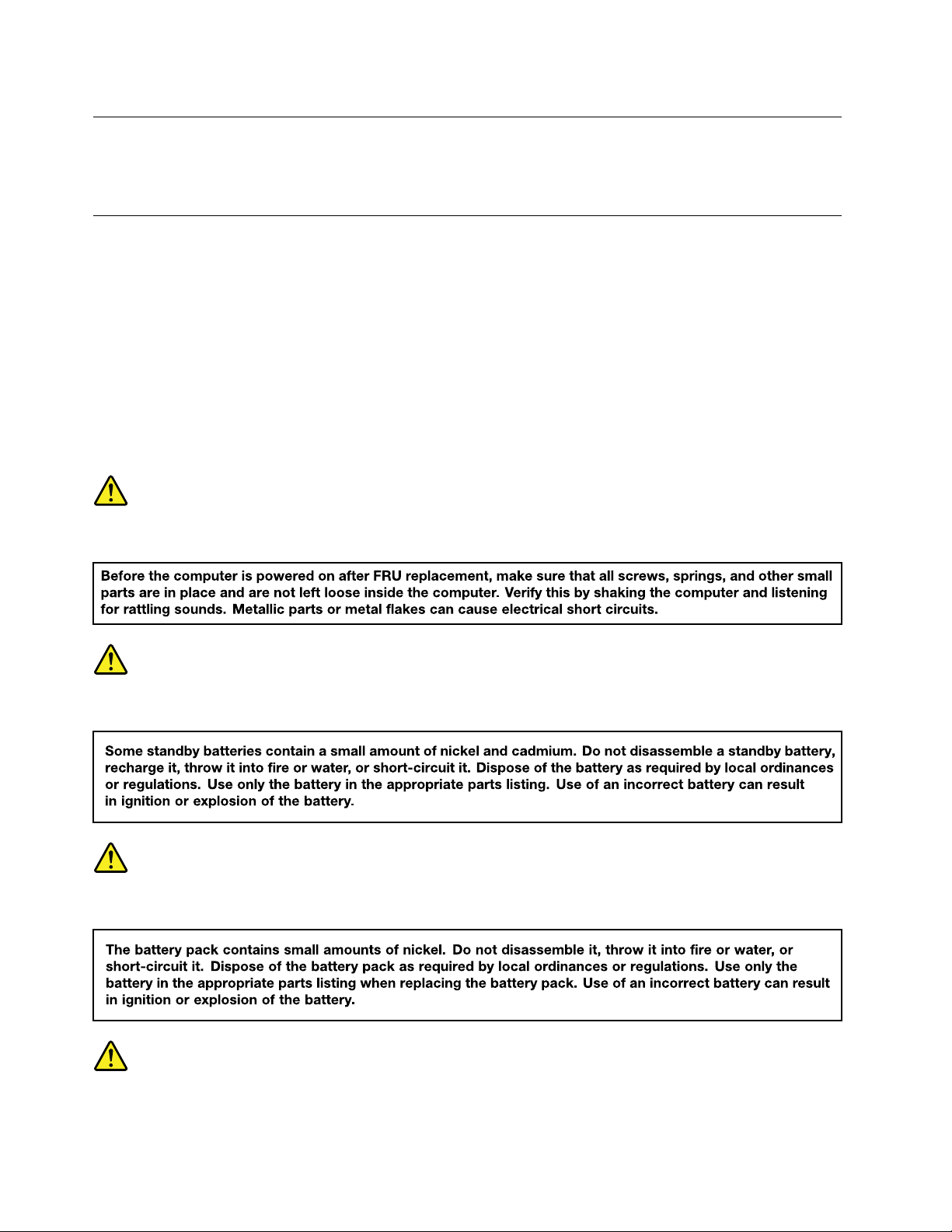
Attention:AfterreplacingaFRU,donotturnonthecomputeruntilyouhaveensuredthatallscrews,springs,
andothersmallpartsareinplaceandnonearelooseinsidethecomputer.Verifythisbyshakingthecomputer
gentlyandlisteningforrattlingsounds.Metallicpartsormetalflakescancauseelectricalshortcircuits.
Attention:ThesystemboardissensitivetoandcanbedamagedbyESD.Beforetouchingit,establish
personalgroundingbytouchingagroundpointwithonehandorbyusinganESDstrap(P/N6405959).
Removetheuppercase(withkeyboard)
Step1.Prythefourrubbersoutoftheirrecesses.
Figure3.Pryrubbersoutofrecesses
Step2.Removethescrews.
©CopyrightLenovo2016
25
Page 32

Figure4.Remove10screws
Table3.Screwspecifications
Screw
location
onbase
cover
Number
10
Specifications
M2.5×6.0mm,flat-head,nylon-coated
Torque
2.5+/-0.2kgf*cm
Step3.TurnovertheChromebookandopentheLCDcoverto180degrees.
Step4.Useaprybartoslidethroughthegroovesbetweentheuppercaseandthebasecover;slowlylift
theuppercaseuntilthekeyboardsocketandthetouchpadsocketappear.
Attention:Donotpulluptheuppercasebeforedetachingthekeyboardandtouchpadcables.
Otherwisethecablesmaybedamaged.
Figure5.Lifttheuppercase
Step5.Openthekeyboardandtouchpadsockets,detachthecables,andpulluptheuppercase.
RefertoTable12“PartnumbersforFRUs(CRUs)”onpage37tolookuptheLenovopartnumbersforthe
followingreplacementparts:
Uppercase
Footrubberpack
Removethebatterypack
MakesurethefollowingFRUs(orCRUs)havebeenremoved.
“Removetheuppercase(withkeyboard)”onpage25
26HardwareMaintenanceManual
Page 33

Step1.Unplugthebatterycablefromthesystemboardandtakethecableoutofthecableguiders.
Attention:Useyourfingernailtopulltheconnectortounplugit.Donotpullthecableitself.
Step2.Removethescrewsandtakeoutthebatterypack.
Figure6.Removescrewsandtakeoutthebatterypack
Table4.Screwspecifications
Screw
location
Batterypack
tobase
cover
Number
3
Specifications
M2×3mm,flat-head,nylon-coated
Torque
1.85+/-
0.15kgf*cm
RefertoTable12“PartnumbersforFRUs(CRUs)”onpage37tolookuptheLenovopartnumbersofthe
followingreplacementparts:
Batterypack
Removethespeakers
MakesurethefollowingFRUs(CRUs)havebeenremoved.
“Removetheuppercase(withkeyboard)”onpage25
“Removethebatterypack”onpage26
Step1.Unplugthespeakers’cablefromthesystemboard.
Figure7.Unplugthespeakers’cablefromthesystemboard
Chapter4.RemovingaFRUorCRU27
Page 34

Step2.Carefullyremovethespeakersoffthepiles.
a
b
RefertoTable12“PartnumbersforFRUs(CRUs)”onpage37tolookuptheLenovopartnumbersof
replacementspeakers.
RemovetheUSBboard
MakesurethefollowingFRUs(CRUs)havebeenremoved:
“Removetheuppercase(withkeyboard)”onpage25
“Removethebatterypack”onpage26
“Removethespeakers”onpage27
Step1.OpenthetwosocketsandthenremovethecablethatconnectstheUSBboardtothesystemboard.
Figure8.Removethecable
Step2.RemoveonescrewandthenremovetheUSBboard.
Table5.Screwspecifications
Screw
location
USBboard
tobase
cover
Number
1
Specifications
M2×3mm,flat-head,nylon-coated
Torque
1.85+/-
0.15kgf-cm
RefertoTable12“PartnumbersforFRUs(CRUs)”onpage37tolookuptheLenovopartnumbersof
replacementUSBboard.
28HardwareMaintenanceManual
Page 35

RemovetheWLAN&Bluetoothcombomodule
a
a
c
MakesurethefollowingFRUs(CRUs)havebeenremovedandthebatteryconnectorhasbeendetached.
“Removetheuppercase(withkeyboard)”onpage25
Step1.DisconnectthewhiteandblackcablesfromtheWLAN&Bluetoothcombomodule.
Figure9.Disconnectantennacables
Step2.Removethescrew.
Table6.Screwspecifications—removingtheWLAN&Bluetoothcombomodule
Screw
location
WLAN&Bluetooth
combocard
tobase
cover
Number
1
SpecificationsColor
M2×3mm,flat-head,nylon-coated
Black
Torque
1.85+/-
0.15kgf-cm
Step3.PullouttheWLAN&Bluetoothcombomoduleinthedirectionshownbythearrow3.
Figure10.PullouttheWLAN&Bluetoothcombomodule
RefertoTable12“PartnumbersforFRUs(CRUs)”onpage37tolookuptheLenovopartnumbersof
replacementWLAN&Bluetoothcombomodules.
RemovetheLCDmodule
MakesurethefollowingFRUs(CRUs)havebeenremovedandthebatteryconnectorhasbeendetached.
“Removetheuppercase(withkeyboard)”onpage25
“RemovetheWLAN&Bluetoothcombomodule”onpage29
Chapter4.RemovingaFRUorCRU29
Page 36

Step1.UnplugtheLCDcable.
c c
c
c
Figure11.Remove4screws
Step2.Removethescrews.
Step3.LiftuptheLCDmoduletodetachitfromthebasecover.
Table7.Screwspecifications—removingtheLCDmodule
Screw
location
LCDto
base
cover
Number
4
Specifications
M2.5×54mm,flat-head,nylon-coated
Torque
2.5+/-0.2kgf*cm
TheLCDmoduleisnotaFRU.Instead,itcontainsFRUsasitscomponents.Referto“DisassembletheLCD
module”onpage32ifyouneedtoreplaceaFRUcontainedintheLCDmodule.
RemovethesystemboardandtheDC-incable
“Removetheuppercase(withkeyboard)”onpage25
“Removethebatterypack”onpage26
“Removethespeakers”onpage27
“RemovetheUSBboard”onpage28
“RemovetheWLAN&Bluetoothcombomodule”onpage29
“RemovetheLCDmodule”onpage29
Step1.UnplugtheDC-incable.
30HardwareMaintenanceManual
Page 37

a
Figure12.UnplugtheDC-incable
d
d
d
d
d
d
d
Step2.Removethescrewsandtakeoutthesystemboard.
Table8.Screwspecifications—removingtheLCDmodule
Screw
location
Screw
used
for
system
7
board
to
base
cover
Figure13.Removethesystemboard
Step3.RemovetheDC-incable.
SpecificationsColor
M2×3mm,flat-head,nylon-coated
Torque
Black
1.85+/-
0.15kgf-cm
Chapter4.RemovingaFRUorCRU31
Page 38

Figure14.RemovetheDC-incable
RefertoTable12“PartnumbersforFRUs(CRUs)”onpage37tolookuptheLenovopartnumbersofthe
followingreplacementparts:
Systemboard
DC-incable
Basecover
DisassembletheLCDmodule
TheLCDmoduleasawholeisnotaFRU.Instead,itcontainsFRUsasitscomponents.Beforedisassembling
theLCDmodule,makesureithasbeendetachedfromthebasecover.Referto“RemovetheLCDmodule”
onpage29forinstructions.
RemovetheLCDbezel
Step1.PrythetworubbersofftheLCDbezel1.
Figure15.Prythetworubbers
Step2.Removethetwoscrews2.
Figure16.Remove2screws
Table9.Screwspecifications—removingtheLCDbezel
Screwlocation
LCDbezelto
LCDbasecover
Number
2
SpecificationsColor
M2.5×4.0mm,flat-head,nylon-coated
Torque
Black
2.5+/-
0.2kgf*cm
32HardwareMaintenanceManual
Page 39

Step3.InsertyourfingernailsunderoneinnersideoftheLCDbezelandtheLCDpanelandthencarefully
pulltheLCDbezeloutwards.RepeatthisactionalongtheinneredgesoftheLCDbezeluntilall
hooksthatsecuretheLCDbezelaredetached
Figure17.RemovetheLCDbezel
3.
Attention:DonotpulltheLCDbezelfromtheoutersideoftheLCDbezel,otherwisethehooks
maybedamaged.
Step4.RemovetheLCDbezel.
RefertoTable13“PartnumbersforLCDFRUs”onpage38tolookuptheLenovopartnumbersforthe
replacementLCDbezel.
RemovetheLCDpanel
MakesurethefollowingFRUs(orCRUs)havebeenremoved.
“RemovetheLCDbezel”onpage32
Step1.Removethefourscrews1;withthebottomedgeasanaxis,liftupthetopedgeoftheLCD
panel
Attention:DonotremovetheLCDpanelatthisstep.TheLCDpanelisconnectedbyacableat
thebackside.DetachthecablebeforeremovingtheLCDpanel.
2.
Chapter4.RemovingaFRUorCRU33
Page 40

a
a
a
a
Figure18.Remove4screwsandliftuptheLCDpanel
c
Table10.Screwspecifications—removingtheLCDpanel
Screw
location
LCD
panel
tobase
cover
Number
4
Specifications
M2×3mm,flat-head,nylon-coated
Torque
1.8+/-0.15kgf*cm
Step2.CheckthebacksideoftheLCDpanelfortheLCDconnectorandthenunplugtheLCDcable3.
Figure19.DisconnecttheL CDcablefromthebackoftheLCDpanel
Step3.RemovetheLCDpanel.
RefertoT able13“PartnumbersforLCDFRUs”onpage38tolookuptheLenovopartnumbersfor
replacementLCDpanels.
RemovethecameraassemblyortheLCD&cameracable
MakesurethefollowingFRUs(orCRUs)havebeenremoved.
“RemovetheLCDbezel”onpage32
“RemovetheLCDpanel”onpage33
Step1.Disconnectthecameracable.
34HardwareMaintenanceManual
Page 41

Figure20.Unplugcameracable
Step2.Removethecamera.
RefertoT able13“PartnumbersforLCDFRUs”onpage38tolookuptheLenovopartnumbersfor
replacementpartsfor:
Cameraassembly
LCD&cameracable
Removethehinges
MakesurethefollowingFRUs(orCRUs)havebeenremoved.
“RemovetheLCDbezel”onpage32
“RemovetheLCDpanel”onpage33
Step1.Removethescrews.
Figure21.Removethescrews
Table11.Screwspecifications—removingthehingesandtheWLANantennas
Screw
location
hinges
toLCD
base
cover
Number
4
Specifications
M2.5×4mm,flat-head,nylon-coated
Torque
2.5+/-0.2kgf*cm
Step2.Removethehinges.
RefertoAppendixA“LenovopartnumbersforreplacementFRUs”onpage37tolookuptheLenovopart
numbersforthereplacementhinges.
Chapter4.RemovingaFRUorCRU35
Page 42

36HardwareMaintenanceManual
Page 43

AppendixA.LenovopartnumbersforreplacementFRUs
Whenservicingacustomer’scomputer,Lenovoservicetechniciansmayusepartnumberslistedinthe
followingtablestoorderreplacementpartsthroughLenovoCRM(customerrelationshipmanagement)
system.
Table12.PartnumbersforFRUs(CRUs)
No.
FRU(CRU)category
2
Footrubberpack
3
Uppercase(withkeyboard)
4
Batterypack
5
Speakers
6
Heatsink
7
Systemboard
PartsdescriptionLenovopartnumber
FootQ80USUP+DOWN
UpperCaseQ80USW/T ouchpad/KBUS5CB0L85364
UpperCaseQ80USW/T ouchpad/KBFRA5CB0L85351
UpperCaseQ80USW/T ouchpad/KBE_FRA5CB0M14127
TeslaSP/AL15M3PB111.1V45Wh3cellbty
TeslaSP/CL15M3PB111.1V45Wh3cellbty
TeslaLGL15L3PB111.1V45Wh3cellbty
SpeakerQ80USL+R5SB0L85356
HeatsinkQ80USW/OF AN
MBQ80VHN30504G16GUMA
MBQ80VHN30504G32GUMA
MBQ80VHN30604G16GUMA
MBQ80VHN30604G32GUMA
MBQ80VHN30502G16GUMA
MBQ80VHN30502G32GUMA
MBQ80VHN30602G16GUMA
MBQ80VHN30602G32GUMA
MBQ80VHN31602G16GUMA
MBQ80VHN31602G32GUMA
MBQ80VHN31604G16GUMA
MBQ80VHN31604G32GUMA
MBQ80VHN37102G16GUMA
MBQ80VHN37102G32GUMA
MBQ80VHN37104G16GUMA
MBQ80VHN37104G32GUMA
5F40M09669
5B10K88047
5B10K88048
5B10K88049
5H40M09667
5B20L85300
5B20L85308
5B20L85301
5B20L85297
5B20L85296
5B20L85302
5B20L85310
5B20L85303
5B20L85298
5B20L85309
5B20L85305
5B20L85304
5B20L85295
5B20L85306
5B20L85311
5B20L85307
©CopyrightLenovo2016
37
Page 44

Table12.PartnumbersforFRUs(CRUs)(continued)
8
WLAN&Bluetoothcombo
module
Intel72652x2AC+BTPCIEM.2WLANSW10H24548
9
DC-incable
DC-INCableQ80US5C10M14090
10
USBboard
USBBoardQ80USW/Cable5C50L85365
11
Lowercase
LowerCoverQ80USBLACK5CB0L85357
Note:RefertoAppendixB“LenovopartnumbersforCRUsandmiscellaneousparts”onpage39tolook
uptheLenovopartnumbersofacpoweradaptersandpowercords.
Table13.PartnumbersforL CDFRUs
No.
FRU(CRU)categorySparepartsdescription
1
LCDbezel
2
LCDpanel
3
Hinges
4
LCDcable
5
Cameraassembly
6
LCDbasecover
LCDBezelQ80USBLACK
AUOB140XTN02.EHW0AHDAGSNB5D10G95364
INN140BGA-EA3HDTAGSNB
BONT140WHM-N41HDTAGSNB
HingeQ80USL+R
LCDCableQ80US5C10L85362
CameraQ80us2MIC5C20L85359
LCDCoverQ80USBLKW/Antenna5CB0L85353
Lenovopartnumber
5B30L85352
5D10K85755
5D10K81099
5H50L85358
38HardwareMaintenanceManual
Page 45

AppendixB.LenovopartnumbersforCRUsandmiscellaneous parts
ThepowercordsandacadaptersareCRUs.
Table14.PartnumbersforFRUs(CRUs)
CRUcategory
Screwpack
acpoweradapter
Powercord
PartsdescriptionLenovopartnumber
ScrewPackQ80USSCREWKIT5S10M09666
ChiconyADLX45NCC3A20V2.25AadapRSA10L02297
AcbelADLX45NAC3A20V2.25AadapRSA10L02298
LINETEKPC323+RVV300/300+LS151米电源线
LINETEKLS15+H03VV-F+LP391米电源线
LINETEKLS15+H03VV-F+LP-381米电源线
LINETEKLS15+H03VV-F+LP-371米电源线
LINETEKLS15H03VV-FLP26A1米电源线
LINETEKLS15+H03VV-F+LP-411米电源线
LINETEKLP-30B+SPT -2+LS151米电源线
LINETEKLP-61L+H03VV-F+LS151米电源线
LINETEKPE-361+H05VV-F+LS151米电源线
LINETEKLS15+H03VV-F+PE-3361米电源线
LINETEKLS15+H05VV-F+LP-E04A1米电源线
LINETEKLS15+H03VV-F+LP-23A1米电源线
LINETEKLS15+VCTF+LP-531米电源线
LINETEKLS15+VCTF+LP-541米电源线
LINETEKLS15+H03VV-F+PE-3641米电源线
LINETEKLP-34+H03VV-F+LS151米电源线
LongwellLSG-31+RVV300/300+LS-181米电源线
LongwellLP-24+H03VV-F+LS-181米电源线
LongwellLP-40+H03VV-F+LS-181米电源线
LongwellLP-37+H03VV-F+LS-181米电源线
LongwellLP-46+H03VV-F+LS-181米电源线
LongwellLP-41+H03VV-F+LS-181米电源线
LongwellLP-30B+SPT-218AWG+LS-181米电源线
LongwellLP-61L+H03VV-F+LS-181米电源线
LongwellLP-67+BIS+LS-181米电源线
145000600
145000599
145000598
145000597
145000596
145000595
145000594
145000593
145000592
145000591
145000590
145000589
145000588
145000587
145000586
145000585
145000568
145000567
145000566
145000565
145000564
145000563
145000562
145000561
145000560
©CopyrightLenovo2016
39
Page 46

Table14.PartnumbersforFRUs(CRUs)(continued)
LongwellLP-22+H03VV-F+LS-181米电源线
LongwellLP-486+KTLH03VV-F+LS-51米电源线
LongwellLP-23A+LFC-3R+LS-181米电源线
LongwellLP-71+VCTF+LS-331米电源线
LongwellLP-54+VCTF+LS-181米电源线
LongwellLP-39+H03VV-F+LS-181米电源线
LongwellLP-34A+H03VV-F+LS-181米电源线
VOLEXGB10S3+RVV300/500+VAC5S1米电源线
VolexUS15S3+SPT-2+VAC5S1米电源线
VOLEXMP5004+H03VV-F+VAC5S1米电源线
VOLEXMP232+H03VV-F+VAC5S1米电源线
VOLEXIT10S3+HO3VV-F+VAC5S1米电源线
VOLEXMP233D+H03VV-F+VAC5S1米电源线
VOLEXM2511+KETIIEC+VAC5S1米电源线
VOLEXAU10S3+H03VV-F+VAC5S1米电源线
VOLEXTW15CS3+VCTF+VAC5S1米电源线
VOLEXVAC5S+VCTF+M7551米电源线
VOLEXVA2073+H03VV-F+VAC5S1米电源线
VOLEXCH10S3+H03VV-F+VAC5S1米电源线
VOLEXSI16S3+H03VV-F+VAC5S1米电源线
VOLEXM2511+HO3VV-F+VAC5S1米电源线
lux0036+RVV300/3000.75/3C+00021米电源线
lux0040+H03VV-F0.75/3C+00111米电源线
lux0048+H03VV-F0.75/3C+00111米电源线
lux0027+H03VV-F0.75/3C+00111米电源线
lux0034+H03VV-F0.75/3C+00111米电源线
lux0041+H03VV-F0.75/3C+00111米电源线
lux0014+SPT -260℃18/3C+00161米电源线
lux0014+H03VV-F0.75/3C+00111米电源线
lux0031+H03VV-F0.75/3C+00111米电源线
lux0046+IS6940.75/3C+00111米电源线
lux0029+H03VV-F0.75/3C+00111米电源线
lux0033+H03VV-F0.75/3C+00111米电源线
lux0038+H03VV-F0.75/3C+00111米电源线
lux0019+VCTF0.75/3C+00211米电源线
lux0018(E)+VCTF0.75/3C+00211米电源线
145000559
145000558
145000557
145000556
145000555
145000554
145000553
145000538
145000537
145000605
145000524
145000535
145000534
145000533
145000532
145000531
145000530
145000528
145000527
145000526
145000525
145500003
145500015
145500014
145500013
145500011
145500012
145500002
5L60J33143
145500000
145500004
145500009
145500008
145500006
145500007
145500005
40HardwareMaintenanceManual
Page 47

Table14.PartnumbersforFRUs(CRUs)(continued)
lux0044+H03VV-F0.75/3C+00111米电源线
lux0033+H03VV-F0.75/3C+00111米电源线
145500010
145500001
AppendixB.LenovopartnumbersforCRUsandmiscellaneousparts41
Page 48

42HardwareMaintenanceManual
Page 49
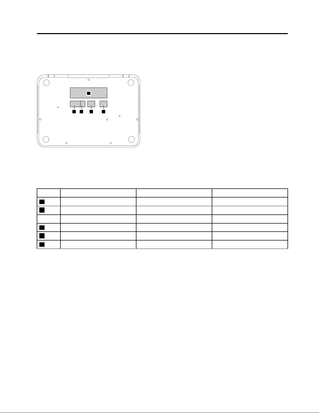
AppendixC.Labellocations
a
d ecb
Figure22.Labellayoutonthebacksideofthebasecover
Labelsattachedtothebasecoverarecountry/regionspecific.Makesuretoapplytheappropriatelabelsto
thereplacementbasecover.
Table15.Allbasecoverlabels
LabelLabeldescription
a
b
c
d
e
Labeldimensions
Ratinglabelandrating(print)label
MalaysiaSIRIMlabel
KoreaKCClabel
Appliedcountry/region
all109mmx24mm
Malaysia15mmx10mm
Korea35mmx12mm
IndonesiaWLANlabelIndonesia32mmx10mm
IndonesiaratinglabelIndonesia32mmx10mm
IsraellabelIsrael32mmx10mm
©CopyrightLenovo2016
43
Page 50

44HardwareMaintenanceManual
Page 51

Trademarks
Lenovoandthe“lenovo”logoaretrademarksofLenovointheUnitedStates,othercountriesorboth:
Othercompany,product,orservicenamesmaybetrademarksorservicemarksofothers.
Page 52

Page 53

Page 54

 Loading...