

Page 1

LenovoStorageN3310
UserGuideandHardwareMaintenance
Manual
MachineTypes:70FXand70FY
Page 2

Note:Beforeusingtheinformationandtheproductitsupports,besuretoreadandunderstandthefollowing:
•TheReadMeFirstthatcomeswithyourproduct
•“Safetyinformation”onpageiii
•AppendixA“Notices”onpage125
FirstEdition(March2015)
©CopyrightLenovo2015.
LIMITEDANDRESTRICTEDRIGHTSNOTICE:IfdataorsoftwareisdeliveredpursuantaGeneralServicesAdministration
“GSA”contract,use,reproduction,ordisclosureissubjecttorestrictionssetforthinContractNo.GS-35F-05925.
Page 3

Contents
Safetyinformation..........iii
Productsthatarenotassessed.........x
Safetyinspectionguide............x
Groundingrequirements............xi
Chapter1.Generalinformation.....1
Introduction.................1
Documentation...............2
Chapter2.Storageproductsetup
roadmap................5
Chapter3.Productoverview......7
Storageproductpackage...........7
Features..................7
Specifications...............11
Software.................12
BIOSandTSMupdateutilities.......12
LenovoThinkServerDeploymentManager..12
LenovoThinkServerSystemManager....13
LenovoThinkServerSystemManager
Premium...............13
Locations.................13
Machinetype,model,andserialnumber
label.................13
Frontviewofthestorageproduct.....14
Frontpanel..............15
Rearviewofthestorageproduct......17
Storageproductcomponents.......19
ThinkServerRAID710Adapter......21
Hot-swap-drivebackplane........22
Systemboardcomponents........23
Systemboardjumpers..........25
Hot-swap-drivestatusLEDs.......27
PowersupplystatusLEDs........28
Connectingthecables..........28
Chapter4.Turningonandturningoff
thestorageproduct..........29
Turningonthestorageproduct........29
Turningoffthestorageproduct........29
Chapter5.Configuringthestorage
product................31
UsingtheSetupUtilityprogram........31
StartingtheSetupUtilityprogram.....31
ViewinginformationintheSetupUtility
program...............31
SetupUtilityprograminterface......31
Settingthesystemdateandtime.....34
Usingpasswords............34
Selectingastartupdevice........35
SettinganEthernetconnectorforsystem
management.............36
ExitingtheSetupUtilityprogram......36
UpdatingorrecoveringtheBIOS......36
ConfiguringRAID..............38
AboutRAID..............38
ConfiguringRAIDusingtheLenovo
ThinkServerDeploymentManagerprogram.39
ConfiguringtheadvancedSATAorSAS
hardwareRAID.............40
Updatingthefirmware............40
Chapter6.Replacinghardware....41
Guidelines................41
Precautions..............41
Handlingstatic-sensitivedevices.....42
Systemreliabilityguidelines........42
Workinginsidethestorageproductwiththe
poweron...............43
Removingorextendingthestorageproductfrom
therackcabinet..............43
Removingthecover............43
Installing,removing,orreplacinghardware...44
Removingandreinstallingtherackhandles.45
Removingandreinstallingthecooling
shroud................46
Installingorremovingamemorymodule...48
InstallingorremovingtheThinkServerSystem
ManagerPremiummodule........55
InstallingorremovingtheRAID110iupgrade
key.................57
InstallingorremovingtheThinkServerRAID
SuperCapacitorModule.........59
InstallingorremovingaPCIecard.....62
Installingorremovingtheopticalmodule..67
Installingorremovingtheintrusionswitch..70
Installingorreplacingaheatsink......72
Installingorreplacingthemicroprocessor..74
Installingorreplacingahot-swapredundant
powersupply.............83
Installingorreplacingahot-swapharddisk
drive.................86
Installingorreplacinga2.5-inchsolid-state
driveintoa3.5-inch-drivebay.......89
Installingorreplacingtheopticaldrive...95
©CopyrightLenovo2015
i
Page 4

Replacingthehot-swaphard-disk-drive
backplane...............98
Replacingasystemfan.........99
Replacingthefrontpanelboard......101
Replacingtherisercardassembly.....103
Replacingthecoin-cellbattery......105
Forservicetechnicianonly:replacingthe
systemboard.............107
Completingthepartsreplacement.......112
Reinstallingthestorageproductcoverand
reconnectingcables...........112
Updatingthestorageproductconfiguration..113
Chapter7.Troubleshootingand
diagnostics.............115
Troubleshootingprocedure..........115
ViewingthestatusanddiagnosticLEDs.....115
Viewingthesystemeventlog.........115
Basictroubleshootingtables.........116
LenovoThinkServerDeploymentManager
programproblems...........116
Opticaldriveproblems..........116
Storagedriveproblems.........117
Memorymoduleproblems........118
Keyboard,mouse,andUSBdevice
problems...............119
Chapter8.Gettinginformation,help,
andservice.............121
Informationresources............121
Usingthedocumentation.........121
LenovoStorageWebsite.........121
LenovoSupportWebsite.........121
Helpandservice..............122
Beforeyoucall.............122
Callingforservice............122
Usingotherservices..........123
Purchasingadditionalservices......123
AppendixA.Notices.........125
Trademarks................126
Importantnotes..............126
PolyvinylChloride(PVC)cableandcordnotice..126
Recyclinginformation............126
Batteryreturnprogram..........127
Requirementforbatteriescontaining
perchlorate..............127
Particulatecontamination..........128
ImportantWEEEinformation.........128
EuropeanUnionRoHS...........129
GermanOrdinanceforWorkglossstatement...129
Exportclassificationnotice..........129
Electronicemissionnotices..........129
FederalCommunicationsCommission(FCC)
Statement...............129
Eurasiancompliancemark..........131
Brazilregulatorynotice...........131
RecyclinginformationforBrazil........131
ENERGYSTARmodelinformation.......132
Index.................133
iiLenovoStorageN3310UserGuideandHardwareMaintenanceManual
Page 5
Safetyinformation
Note:Beforeusingtheproduct,besuretoreadandunderstandthemultilingualsafetyinstructionsonthe
documentationDVDthatcomeswiththeproduct.
Antesdeusaroproduto,leiaeentendaasinstruçõesdesegurançamultilínguesnoDVDdedocumentação
queoacompanha.
Предидаизползватетозипродукт,задължителнопрочететеивникнетевмногоезичнитеинструкции
забезопасноствDVDдискасдокументация,койтосепредоставяспродукта.
PrijeupotrebeovogproizvodaobaveznopročitajtevišejezičnesigurnosneuputekojesenalazenaDVD-us
dokumentacijomkojidobivateuzproizvod.
PředpoužitímproduktujetřebasipřečístaporozumětbezpečnostnímpokynůmuvedenýmnadiskuDVDs
dokumentací,kterýjedodávánsproduktem.
Førdubrugerproduktet,skaldusørgeforatlæseogforstådesikkerhedsforskrifter,derfindespåflere
sprog,pådendokumentations-dvd,derfølgermedproduktet.
LuetuotteenmukanatoimitetullaDVD-tietolevylläolevatmonikielisetturvaohjeetennentämäntuotteen
käyttöä.
Avantd'utiliserleproduit,veillezàbienlireetcomprendrelesinstructionsdesécuritémultilinguesfigurant
surleDVDdedocumentationfourniavecleproduit.
Πρινχρησιμοποιήσετετοπροϊόν,βεβαιωθείτεότιέχετεδιαβάσεικαικατανοήσειτιςοδηγίεςασφάλειας,οι
οποίεςείναιδιαθέσιμεςσεδιάφορεςγλώσσεςστοDVDτεκμηρίωσηςπουσυνοδεύειτοπροϊόν.
VorVerwendungdesProduktssolltenSieunbedingtdiemehrsprachigenSicherheitsanweisungenaufder
Dokumentations-DVDlesen,dieimLieferumfangdesProduktsenthaltenist.
AtermékhasználataelőttmindenképpenolvassaelésértelmezzeatermékhezkapottdokumentációsDVD
lemezentalálható,többnyelvenelolvashatóbiztonságielőírásokat.
Primadiutilizzareilprodotto,accertarsidileggereecomprendereleinformazionisullasicurezzamultilingue
disponibilisulDVDdidocumentazionefornitoconilprodotto.
製品をご使用になる前に、製品に付属のDocumentationDVDに収録されているマルチリンガルの「安
全に正しくご使用いただくために」を読んで理解してください。
제품을사용하기전에제품과함께제공되는문서DVD의다국어안전지침을주의깊게읽어보십시오.
Voordatuhetproductgebruikt,moetuervoorzorgendatudemeertaligeveiligheidsinstructiesopde
documentatie-dvdvanhetproducthebtgelezenenbegrijpt.
©CopyrightLenovo2015
iii
Page 6

Przedskorzystaniemzproduktunależyzapoznaćsięzwielojęzycznymiinstrukcjamibezpieczeństwa
znajdującymisięnapłycieDVDzdokumentacjądostarczonąwrazzproduktem.
Antesdeutilizaroproduto,leiaatentamenteasinstruçõesdesegurançamultilinguesqueconstamno
DVDdedocumentaçãofornecidocomoproduto.
Înaintedeautilizaprodusul,asiguraţi-văcăaţicititşiînţelesinstrucţiuniledesiguranţăînmaimultelimbide
peDVD-ulcudocumentaţiecareînsoţeşteprodusul.
Førdubrukerproduktet,måduleseogforstådenflerspråkligesikkerhetsinformasjonenpåDVDenmed
dokumentasjonsomfølgermedproduktet.
Преждечемиспользоватьэтотпродукт ,внимательноознакомьтесьсинструкциямипотехнике
безопасностинаразныхязыках,которыеможнонайтинаDVD-дискесдокументациейвкомплектес
продуктом.
在使用本产品之前,请务必先阅读和了解产品附带的文档DVD中的多语言安全说明。
Prenegotoupotrebiteproizvodobaveznopaljivoproitajteiprouiteviejezikouputstvozabezbednostna
dokumentacionomDVD-ukojistedobiliuzproizvod.
PredpouvanmproduktusipretajteviacjazynbezpenostnpokynynadiskuDVDsdokumentcioudodanoms
produktom.
Predenzačneteuporabljatiizdelek,jepomembno,daprebereteinrazumetevečjezičnavarnostnanavodila
naDVD-juzdokumentacijo,kistegaprejeliskupajzizdelkom.
Antesdeutilizarelproducto,asegúresedeleerycomprenderlasinstruccionesdeseguridadmultilingüesdel
DVDdedocumentaciónqueseproporcionaconelproducto.
Varnogamedattläsasäkerhetsinstruktionernapådokumentations-DVD-skivansomföljermedprodukten
innandubörjaranvändaprodukten.
使用本產品之前,請務必閱讀並瞭解產品隨附的文件DVD上的多國語言版本安全資訊。
Buürünükullanmadanönce,ürünlebirliktegönderilenbelgeDVD'siüzerindekiçokdiliçerengüvenlik
yönergeleriniokuyupanladýðýnýzdaneminolun.
Передвикористаннямцьогопродуктууважноознайомтесязінструкціямизтехнікибезпекинарізних
мовах,щоможназнайтинаDVD-дискуздокументацієювкомплектізпродуктом.
Important:Fortranslatedversionsofthecautionordangerstatement,refertotheSafety,Warranty,and
SupportInformationdocument.
Ensurethatyoureadandunderstandallcautionanddangerstatementsinthisdocumentbeforeyouperform
theprocedures.Readandunderstandanyadditionalsafetyinformationthatisincludedwiththestorage
productoroptionaldevicebeforeyouinstall,remove,orreplacethedevice.
ivLenovoStorageN3310UserGuideandHardwareMaintenanceManual
Page 7
Statement1
DANGER
Electricalcurrentfrompower,telephone,andcommunicationcablesishazardous.
Toavoidashockhazard:
•Donotconnectordisconnectanycablesorperforminstallation,maintenance,orreconfigurationofthis
productduringanelectricalstorm.
•Connectallpowercordstoaproperlywiredandgroundedelectricaloutlet.
•Ensurethatallpowercordconnectorsaresecurelyandcompletelypluggedintoreceptacles.
•Connecttoproperlywiredoutletsanyequipmentthatwillbeattachedtothisproduct.
•Whenpossible,useonehandonlytoconnectordisconnectsignalcables.
•Neverturnonanyequipmentwhenthereisevidenceoffire,water,orstructuraldamage.
•Disconnecttheattachedpowercords,telecommunicationssystems,networks,andmodemsbeforeyou
openthedevicecovers,unlessinstructedotherwiseintheinstallationandconfigurationprocedures.
•Connectanddisconnectcablesasdescribedinthefollowingtablewheninstalling,moving,oropening
coversonthisproductorattacheddevices.
Toconnect:Todisconnect:
1.TurneverythingOFF .
2.First,attachallcablestodevices.
3.Attachsignalcablestoconnectors.
4.Attachpowercordstooutlets.
5.TurndevicesON.
1.TurneverythingOFF .
2.First,removepowercordsfromoutlets.
3.Removesignalcablesfromconnectors.
4.Removeallcablesfromdevices.
Statement2
DANGER
Dangerofexplosionifbatteryisincorrectlyreplaced.
Whenreplacingthelithiumcoincellbattery,useonlythesameoranequivalenttypethatis
recommendedbythemanufacturer .Thebatterycontainslithiumandcanexplodeifnotproperly
used,handled,ordisposedof.
Donot:
•Throworimmerseintowater
•Heattomorethan100°C(212°F)
•Repairordisassemble
Disposeofthebatteryasrequiredbylocalordinancesorregulations.
©CopyrightLenovo2015
v
Page 8

Statement3
CAUTION:
Whenlaserproducts(suchasCD-ROMs,DVDdrives,fiberopticdevices,ortransmitters)are
installed,notethefollowing:
•Donotremovethecovers.Removingthecoversofthelaserproductcouldresultinexposureto
hazardouslaserradiation.Therearenoserviceablepartsinsidethedevice.
•Useofcontrolsoradjustmentsorperformanceofproceduresotherthanthosespecifiedherein
mightresultinhazardousradiationexposure.
DANGER
SomelaserproductscontainanembeddedClass3AorClass3Blaserdiode.Notethefollowing:
Laserradiationwhenopen.Donotstareintothebeam,donotviewdirectlywithoptical
instruments,andavoiddirectexposuretothebeam.
Statement4
≥18kg(39.7lb)≥32kg(70.5lb)≥55kg(121.2lb)
<32kg(70.5lb)<55kg(121.2lb)<100kg(220.5lb)
CAUTION:
Usesafepracticeswhenlifting.
Statement5
CAUTION:
Thepowercontrolbuttononthedeviceandthepowerswitchonthepowersupplydonotturnoff
theelectricalcurrentsuppliedtothedevice.Thedevicealsomighthavemorethanonepower
cord.T oremoveallelectricalcurrentfromthedevice,ensurethatallpowercordsaredisconnected
fromthepowersource.
viLenovoStorageN3310UserGuideandHardwareMaintenanceManual
Page 9
Statement6
CAUTION:
Ifyouinstallastrain-reliefbracketoptionovertheendofthepowercordthatisconnectedtothe
device,youmustconnecttheotherendofthepowercordtoapowersourcethatiseasilyaccessible
incaseitneedstobedisconnected.
Statement7
CAUTION:
Ifthedevicehasdoors,ensurethatyouremoveorsecurethedoorsbeforemovingorliftingthe
devicetoprotectagainstpersonalinjury.Thedoorswillnotsupporttheweightofthedevice.
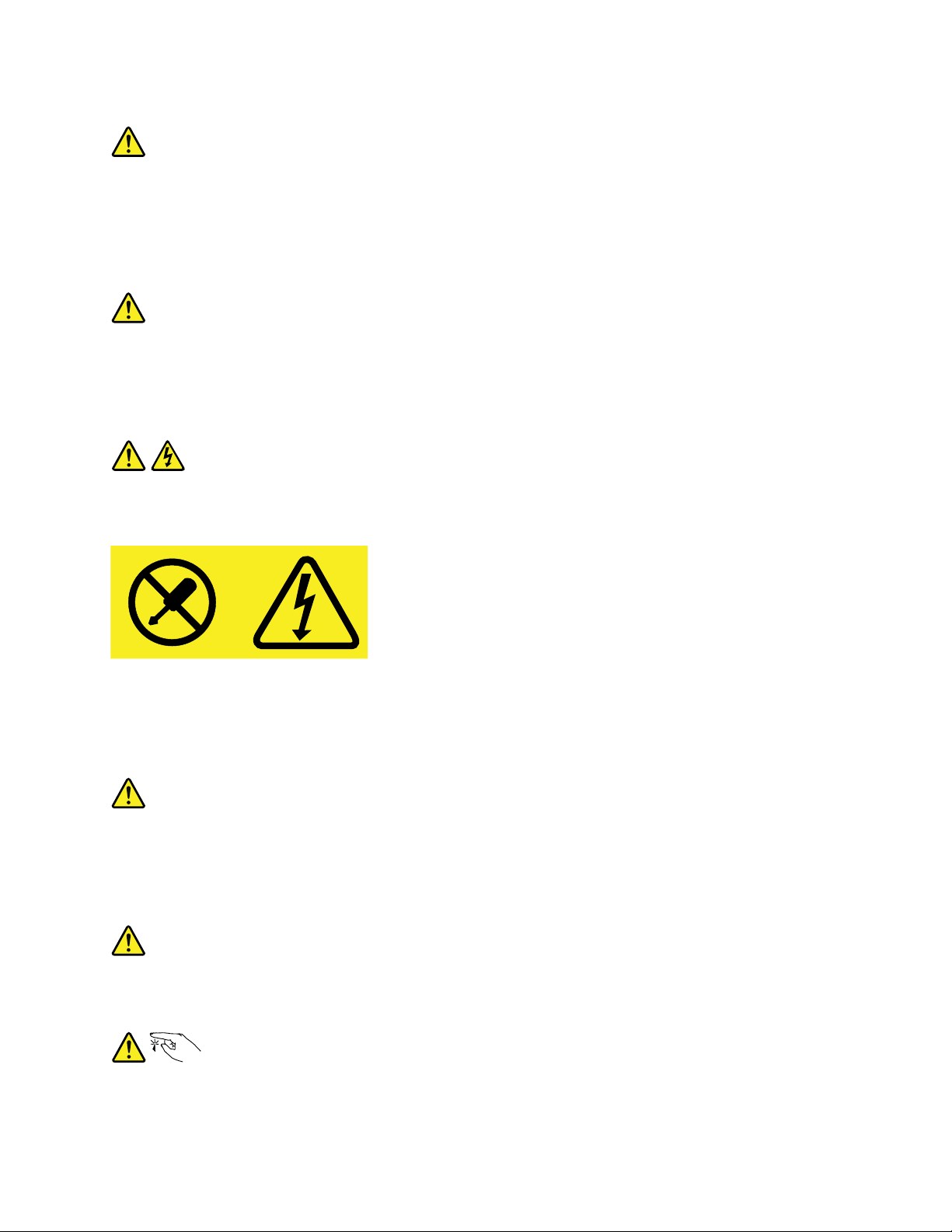
Statement8
CAUTION:
Neverremovethecoveronapowersupplyoranypartthathasthefollowinglabelattached.
Hazardousvoltage,current,andenergylevelsarepresentinsideanycomponentthathasthislabel
attached.Therearenoserviceablepartsinsidethesecomponents.Ifyoususpectaproblemwith
oneoftheseparts,contactaservicetechnician.
Statement9
CAUTION:
Disconnectthehot-swapfancablesbeforeremovingthefanfromthedevicetoprotectagainst
personalinjury.
Statement10
CAUTION:
Thefollowinglabelindicatesasharp-edgehazard.
©CopyrightLenovo2015
vii
Page 10
Statement11
CAUTION:
Thefollowinglabelindicatesapotentialheathazard.
Statement12
DANGER
Overloadingabranchcircuitisapotentialfirehazardandashockhazardundercertainconditions.T o
avoidthesehazards,ensurethatyoursystemelectricalrequirementsdonotexceedbranchcurrentratings
attheinstallationsite.
Statement13
CAUTION:
Ensurethattherackissecuredproperlytoavoidtippingwhenthestorageunitisextendedontherails.
Statement14
CAUTION:
SomeaccessoryoroptionboardoutputsexceedClass2orlimitedpowersourcelimits.You
mustinstalltheappropriateinterconnectingcablinginaccordancewithyourlocalelectricalcode
requirements.
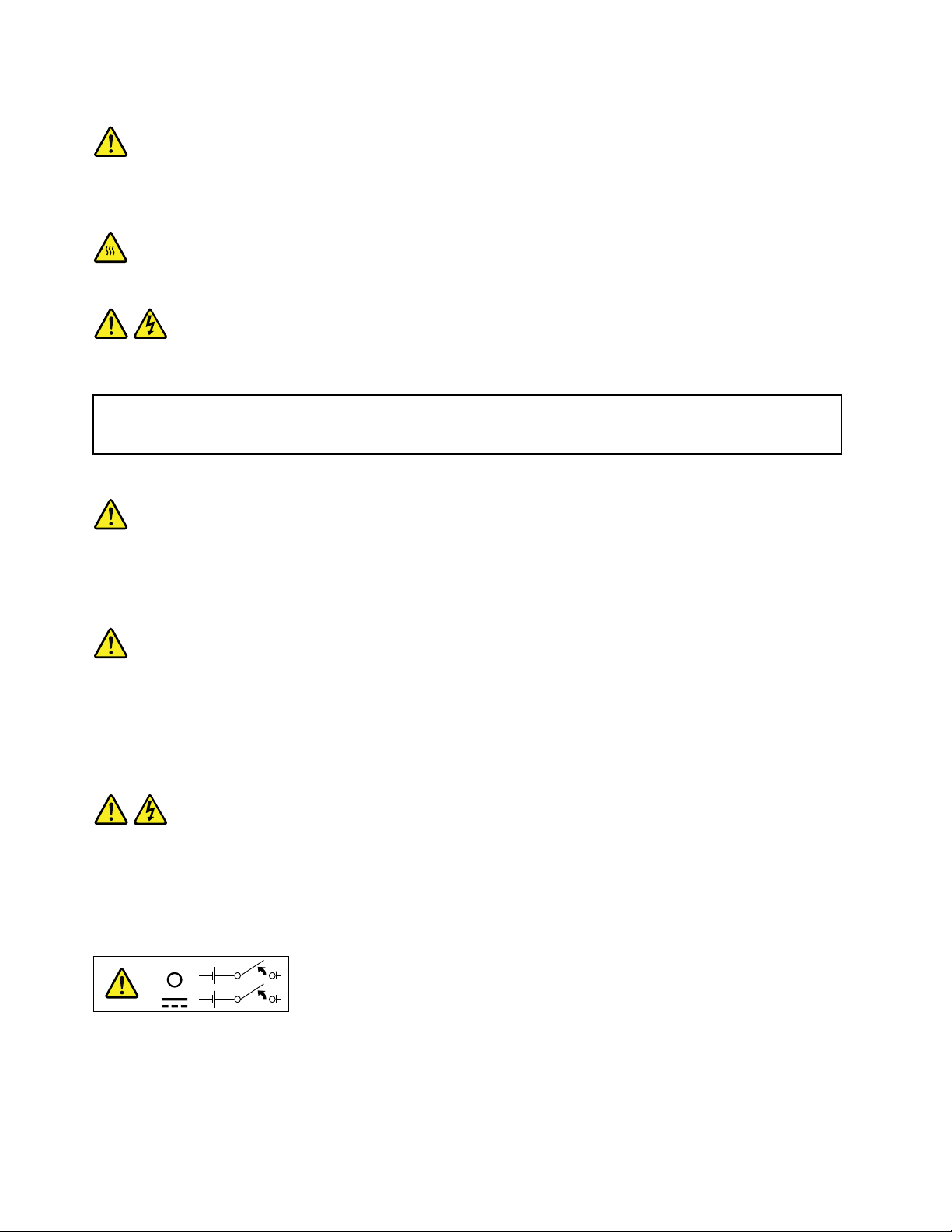
Statement15
CAUTION:
Thepower-controlbuttononthedevicemayputthedeviceinstandbymodeinsteadofturningoff
thedevice.Inaddition,thedevicemighthavemultipleconnectionstodcpower.T oremoveall
electricalcurrentfromthedevice,ensurethatallconnectionstodcpoweraredisconnectedat
thedcpowerinputterminals.
viiiLenovoStorageN3310UserGuideandHardwareMaintenanceManual
Page 11

Statement16
CAUTION:
Toreducetheriskofelectricshockorenergyhazards:
•Thisequipmentmustbeinstalledbytrainedservicepersonnelinarestricted-accesslocation,as
definedbyyourlocalelectricalcodeandthelatesteditionofIEC60950.
•Thebranchcircuitovercurrentprotectionmustberatedinaccordancewithlocalelectricalcode
requirements.
•Use1.3mm
2
or16AmericanWireGauge(AWG)copperconductoronly,notexceeding3meters
inlength.
•Torquethewiring-terminalscrewsto1.4newton-metersor12inch-pounds.
•Provideareadilyavailable,approvedandrateddisconnectdeviceinthefieldwiring.
Statement17
CAUTION:
ThisproductcontainsaClass1Mlaser.Donotviewdirectlywithopticalinstruments.
Statement18
CAUTION:
Donotplaceanyobjectontopofrack-mountedproducts.
Statement19
CAUTION:
Hazardousmovingparts.Keepfingersandotherbodypartsaway.
©CopyrightLenovo2015
ix
Page 12

Statement20
CAUTION:
Alithiumionbatteryisprovided.T oavoidpossibleexplosion,donotburnthebattery.Replacethe
batteryonlywiththeLenovo-approvedpart.Recycleordiscardthebatteryasinstructedbylocal
regulations.
Productsthatarenotassessed
Typicalproductsthatarenotassessedincludebutnotlimitedtothefollowing:
•StorageandIT-rackcomponents(forexample,uninterruptiblepowersuppliesandcurrentdistribution
systems)
•DevicesinITrooms(forexample,bulkstorageunitsandnetworkproducts)
•Industriallow-voltageswitchgear
Safetyinspectionguide
Thepurposeofthisinspectionguideistoassistyouinidentifyingpotentiallyunsafeconditions.Aseach
machinewasdesignedandbuilt,requiredsafetyitemswereinstalledtoprotectusersandservicetechnicians
frominjury.Thisguideaddressesonlythoseitems.Youshouldusegoodjudgmenttoidentifypotentialsafety
hazardsduetoattachmentofnon-LenovoStoragefeaturesoroptionsnotcoveredbythisinspectionguide.
Ifanyunsafeconditionsarepresent,youmustdeterminehowserioustheapparenthazardcouldbeand
whetheryoucancontinuewithoutfirstcorrectingtheproblem.
Considertheseconditionsandthesafetyhazardstheypresent:
•Electricalhazards,especiallyprimarypower(primaryvoltageontheframecancauseseriousorfatal
electricalshock)
•Explosivehazards,suchasadamagedCathodeRayTube(CRT)monitororabulgingcapacitor
•Mechanicalhazards,suchaslooseormissinghardware
Todeterminewhetherthereareanypotentiallyunsafeconditions,usethefollowingchecklistatthebeginning
ofeveryservicetask.Beginthecheckswiththepoweroff,andthepowercordsdisconnected.
Checklist:
1.Checkexteriorcoversfordamage(loose,broken,orsharpedges).
2.Poweroffthestorage.Disconnectthepowercords.
3.Checkthepowercordfor:
a.Athird-wiregroundconnectoringoodcondition.Useametertomeasurethird-wireground
continuityfor0.1ohmorlessbetweentheexternalgroundpinandtheframeground.
b.Thepowercordshouldbetheauthorizedtypespecifiedforyourstorage.Goto:
http://www.lenovo.com/serviceparts-lookup
c.Insulationmustnotbefrayedorworn.
4.Checkforcrackedorbulgingbatteries.
5.Removethecover.
6.Checkforanyobviousnon-LenovoStoragealterations.Usegoodjudgmentastothesafetyofany
non-LenovoStoragealterations.
xLenovoStorageN3310UserGuideandHardwareMaintenanceManual
Page 13

7.Checkinsidetheunitforanyobviousunsafeconditions,suchasmetalfilings,contamination,wateror
otherliquids,orsignsoffireorsmokedamage.
8.Checkforworn,frayed,orpinchedcables.
9.Checkthatthepower-supplycoverfasteners(screwsorrivets)havenotbeenremovedortamperedwith.
Groundingrequirements
Electricalgroundingofthestorageisrequiredforoperatorsafetyandcorrectsystemfunction.Proper
groundingoftheelectricaloutletcanbeverifiedbyacertifiedelectrician.
©CopyrightLenovo2015
xi
Page 14

xiiLenovoStorageN3310UserGuideandHardwareMaintenanceManual
Page 15

Chapter1.Generalinformation
Thischapterprovidessomegeneralinformationaboutyourproduct.
Thischaptercontainsthefollowingitems:
•“Introduction”onpage1
•“Documentation”onpage2
Introduction
ThisdocumentforyourLenovo
thestorageproductfeatures,specifications,componentlocations,configurationinstructions,hardware
replacementprocedures,andbasictroubleshootinganddiagnostics.
YourstorageproductcomeswithadocumentationDVDthatcontainsvariousstorageproductdocumentsto
helpyouuseandmaintainthestorageproduct.
TheLenovoLimitedWarranty(LLW)containsthewarrantytermsthatapplytotheproductyou
purchasedfromLenovo.ReadtheLLWonthedocumentationDVDthatcomeswithyourstorage
product.AprintablegenericversionofthelatestLLWalsoisavailableinmorethan30languagesat
http://www.lenovo.com/warranty/llw_02.IfyoucannotobtaintheLLWthroughthedocumentationDVDor
LenovoWebsite,contactyourlocalLenovoofficeorresellertoobtainaprintedversionoftheLLW,free
ofcharge.
®
network-attachedstorage(NAS)productcontainsinformationabout
Forwarrantyservice,consulttheworldwideLenovoSupporttelephonelist.T elephonenumbersaresubject
tochangewithoutnotice.Themostup-to-datetelephonelistforLenovoSupportisalwaysavailableonthe
Websiteathttp://www.lenovo.com/support/phone.Ifthetelephonenumberforyourcountryorregionisnot
listed,contactyourLenovoresellerorLenovomarketingrepresentative.
Toobtainthemostup-to-dateinformationaboutthestorageproduct,goto:
http://shop.lenovo.com/us/en/servers/network-storage/
LenovomaintainspagesontheWorldWideWeb,whereyoucangetthelatesttechnicalinformationand
downloaddocumentationordevicedriversandupdates.ToaccesstheLenovoSupportWebsite,goto:
http://www.lenovo.com/support
©CopyrightLenovo2015
1
Page 16

Recordinformationaboutyourstorageproductinthefollowingtable.Y ouwillneedtheinformationifyou
everneedtohaveyourstorageproductserviced.
Forwheretofindtheproductinformationlabelonthechassis,see“Machinetype,model,andserialnumber
label”onpage13
.
Productname
Machinetypeandmodel(MT-M)
Serialnumber(S/N)
Dateofpurchase
______________________________________________
______________________________________________
______________________________________________
______________________________________________
YoucanregisteryourstorageproductwithLenovobyfollowingtheinstructionsat:
http://www.lenovo.com/register
Whenyouregisteryourstorageproduct,informationisenteredintoadatabase,whichenablesLenovoto
contactyouincaseofarecallorothersevereproblem.AfteryouregisteryourstorageproductwithLenovo,
youwillreceivequickerservicewhenyoucallLenovoforhelp.Inaddition,somelocationsofferextended
privilegesandservicestoregisteredusers.
Documentation
Thistopicprovidesageneraldescriptionofeachdocumentforyourstorageproductandinstructionsonhow
toobtainallthedocuments.
Printeddocuments
Thefollowingdocumentsareprintedoutandincludedinyourstorageproductpackage.
•GettingStartedGuide
Thisdocumentprovidesgeneralinformationtohelpyougetfamiliarwithyourstorageproduct.
•RackInstallationInstructions(availableonsomemodels)
Thisdocumentprovidesinstructionsonhowtoinstallyourstorageproductintoastandardrackcabinet
byusingtherailkitshippedwiththestorageproduct.
Note:Dependingonthemodel,aprintedEnglishversionofthisdocumentmightbeincludedinyour
storageproductpackage.PDFversionsofotherlanguagesareprovidedonthedocumentationDVD
thatcomeswithyourstorageproduct.
2LenovoStorageN3310UserGuideandHardwareMaintenanceManual
Page 17

DocumentationDVD
ThedocumentationDVD,whichcomeswithyourstorageproduct,containsvariousdocumentsforyour
storageproductinPortableDocumentFormat(PDF)andHyperT extMarkupLanguage(HTML).The
documentationDVDisnotbootable.ToviewthedocumentsontheDVD,youwillneedacomputerwitha
WebbrowserandtheAdobeReaderprogram,whichisavailablefordownloadat:
http://www.adobe.com
TostartthedocumentationDVD,inserttheDVDintotheopticaldrive.TheDVDisAutoPlayenabledand
startsautomaticallyinmostMicrosoft
®
Linux
operatingsystem,openthelaunch.htmfilelocatedintherootdirectoryoftheDVD.
®
Windows
®
environments.IftheDVDfailstostartorifyouareusinga
Note:LenovomaintainspagesontheWorldWideWeb,whereyoucangetthelatesttechnicalinformation
anddownloaddocumentationordevicedriversandupdates.Someinformationinthedocumentsonthe
documentationDVDmightchangewithoutnoticeafterthefirstreleaseoftheDVD.Y oucanalwaysobtainall
themostup-to-datedocumentationforyourstorageproductfromtheLenovoWebsiteat:
http://www.lenovo.com/support
ThefollowingdocumentsareonthedocumentationDVDthatcomeswithyourstorageproduct:
•Safety,Warranty,andSupportInformation
Thisisamultilingualdocumentthatincludesallthesafetystatementsforyourproductinmorethan30
languages.Besuretoreadandunderstandallthesafetystatementsbeforeusingtheproduct.This
documentalsoincludestheLenovowarrantystatement,CustomerReplaceableUnits(CRUs)information,
andinformationabouthowtocontacttheLenovoCustomerSupportCenter.
•LenovoLicenseAgreement
ThisdocumentincludesthetermsandconditionsoftheLenovoLicenseAgreement.
•UserGuideandHardwareMaintenanceManual
Thisdocumentprovidesdetailedinformationtohelpyougetfamiliarwithyourstorageproductandhelp
youuse,configure,andmaintainyourstorageproduct.
•RackInstallationInstructions
Thisdocumentprovidesinstructionsonhowtoinstallyourstorageproductintoastandardrackcabinet
byusingtherailkitshippedwiththestorageproduct.
•NASAdministratorGuide
Thisdocumentprovidesinstructionsonhowtomanageyourstorageproductusingtheprogramsand
utilitiesthatcomewiththeMicrosoftWindowsStorageServer2012R2operatingsystem.
Chapter1.Generalinformation3
Page 18

4LenovoStorageN3310UserGuideandHardwareMaintenanceManual
Page 19

Chapter2.Storageproductsetuproadmap
Thischapterprovidesageneralroadmaptoguideyouthroughsettingupyourstorageproduct.
Thestorageproductsetupprocedurevariesdependingontheconfigurationofthestorageproductwhen
itwasdelivered.Insomecases,thestorageproductisfullyconfiguredandyoujustneedtoconnectthe
storageproducttothenetworkandanacpowersource,andthenyoucanturnonthestorageproduct.In
othercases,thestorageproductneedstohavehardwarefeaturesinstalled,requireshardwareandfirmware
configuration,andrequiresanoperatingsystemtobeinstalled.
Thegeneralprocedureforsettingupyourstorageproductis:
1.Unpackthestorageproductpackage.See“Storageproductpackage”onpage7.
2.Installanyrequiredhardwareorstorageproductoption.SeetherelatedtopicsinChapter6“Replacing
hardware”onpage41.
3.Ifnecessary,installthestorageproductintoastandardrackcabinetbyusingtherailkitshippedwith
thestorageproduct.SeetheRackInstallationInstructionsthatcomeswiththestorageproduct.
4.ConnecttheEthernetcableandpowercordstothestorageproduct.See“Rearviewofthestorage
product”onpage17
5.Turnonthestorageproducttoverifyoperation.See“Turningonthestorageproduct”onpage29.
6.ReviewtheUnifiedExtensibleFirmwareInterface(UEFI)settingsandcustomizeasneeded.See“Using
theSetupUtilityprogram”onpage31
7.ConfigureRAIDandinstalltheoperatingsystemandbasicdrivers.See“LenovoThinkServer
DeploymentManager”onpage12
8.Installanyadditionaldriversneededforaddedfeatures.Refertotheinstructionsthatcomewiththe
hardwareoption.
9.ConfigureEthernetsettingsintheoperatingsystembyreferringtotheoperatingsystemhelp.This
stepisnotrequirediftheoperatingsystemwasinstalledusingtheLenovoThinkServerDeployment
Managerprogram.
10.Checkforfirmwareupdates.See“Updatingthefirmware”onpage40.
11.Installmanagementapplicationsandanyotherapplications.Refertothedocumentationthatcomes
withtheapplicationsthatyouwanttoinstall.
tolocatetheconnectors.
.
and“ConfiguringRAID”onpage38.
©CopyrightLenovo2015
5
Page 20

6LenovoStorageN3310UserGuideandHardwareMaintenanceManual
Page 21

Chapter3.Productoverview
Thischapterprovidesinformationaboutthestorageproductpackage,features,specifications,software
programs,andcomponentlocations.
Thischaptercontainsthefollowingitems:
•“Storageproductpackage”onpage7
•“Features”onpage7
•“Specifications”onpage11
•“Software”onpage12
•“Locations”onpage13
Storageproductpackage
Thestorageproductpackageincludesthefollowingitems:
•Storageproduct
•Railkit(availableonsomemodels)
•Cablemanagementarmorcablemanagementbar(availableonsomemodels)
•Slimopticaldrive(availableonsomemodels)
•Materialbox,includingitemssuchaspowercords,printeddocumentation,andadocumentationDVD
Features
Thistopicprovidesgeneralinformationaboutthestorageproductfeaturesforvariousmodels.Depending
onyourspecificmodel,somefeaturesmightvaryornotapply.Forinformationaboutyourspecificmodel,
usetheSetupUtilityprogram.See“ViewinginformationintheSetupUtilityprogram”onpage31
canrefertotheProductSpecificationsReferencedocumentforLenovoStorageproductsat:
http://www.lenovo.com/psref/
Microprocessor
OneortwoIntel
Memory
Yourstorageproducthas16memoryslots.Formoreinformation,see“Memorymoduleinstallationrules”
onpage48.
®
®
Xeon
microprocessors(internalcachesizevariesbymodel)
.Youalso
©CopyrightLenovo2015
7
Page 22

Powersupply
Yourstorageproductcomeswithoneortwopowersupplies.Whentwopowersuppliesarebothinstalled,
theyprovideredundantandhot-swapfeatures.Dependingonthestorageproductmodel,thepower
suppliesforyourstorageproductcanbeanyofthefollowingtypes:
•450-watt,90–264Vac,universalinputandcompliantwith80PLUSGold
•550-watt,90–264Vac,universalinputandcompliantwith80PLUSPlatinum
•750-watt,90–264Vac,universalinputandcompliantwith80PLUSPlatinum
•750-watt,180–264Vac,universalinputandcompliantwith80PLUSTitanium
Systemfans
Yourstorageproductsupportsuptosixsystemfans.Thisdesignhelpsyouavoidsignificantcooling
problemswhenasystemfanfails.
Internaldrives
Internaldrivesaredevicesthatyourstorageproductusestoreadandstoredata.Theinternaldrives
supportedbyyourstorageproductvarybymodel.
•Internalstoragedrive
Yourstorageproductsupportsuptofour3.5-inchhot-swapSerialAdvancedTechnologyAttachment
(SATA)harddiskdrives,SerialAttachedSCSI(SAS)harddiskdrives(SCSIistheacronymforSmall
ComputerSystemInterface),orsolid-statedrives.
Note:Youcaninstalla2.5-inchsolid-statedriveintoa3.5-inch-drivebay.Formoreinformation,see
“Installinga2.5-inchsolid-statedriveintoa3.5-inchhard-disk-drivebay”onpage90
.
•Opticaldrive
–OneslimSATAopticaldriveinsomemodels
Tolocatetheinternaldrivesordrivebays,see“Storageproductcomponents”onpage19.
Expansionslots
•OnePCIExpress(PCIe)slotonthesystemboard
•OnePCIeslotoneachrisercard
•Tworisercardassemblyslotsonthesystemboard
Fordetailedinformation,see“Rearviewofthestorageproduct”onpage17.
8LenovoStorageN3310UserGuideandHardwareMaintenanceManual
Page 23

Input/Output(I/O)features
•Ontherearpanel:
–Onevideographicsarray(VGA)DB-15connector
–Oneserialconnector
–ThreeRJ-45Ethernetconnectors(Ethernetconnector0isforsystemmanagement)
–TwoUSB3.0connectors
•Onthefrontpanel:
–OneDisplayPortconnector
–TwoUSB2.0connectors
Tolocatetheconnectors,refertotherelatedtopicsin“Locations”onpage13.
Videosubsystem
AnintegratedgraphicscontrollerisavailableinyourstorageproducttosupportDisplayPortconnectors
forconnectingvideodevices.TheintegratedgraphicscontrollerislocatedintheBaseboardManagement
Controller(BMC)chiponthesystemboard.
•Integratedgraphicscontroller:on-boardASPEEDAST2400
•16MBofvideomemorycache
Ethernetconnectivity
TherearethreeRJ-45Ethernetconnectorsontherearpanelwith10megabitspersecond(Mbps),100Mbps,
or1000Mbpsnetworkconnectivity.Ethernetconnector0isforsystemmanagementbydefault.However,
youalsocansetEthernetconnector1or2forsystemmanagementuseintheSetupUtilityprogram.
Formoreinformation,see“Rearviewofthestorageproduct”onpage17.
Reliability,availability,andserviceability
Reliability,availability,andserviceability(hereinafterreferredtoasRAS)arethreeimportantstorageproduct
designfeatures.TheRASfeatureshelpyouensuretheintegrityofthedatastoredonthestorageproduct,
theavailabilityofthestorageproductwhenyouneedit,andtheeasewithwhichyoucandiagnoseand
correctproblems.
YourstorageproducthasthefollowingRASfeatures:
•Securityfeatures
–Administratorpasswordanduserpasswordtohelpprotectunauthorizedaccesstothestorageproduct
(see“Usingpasswords”onpage34
)
–Remotemonitoringorcontrolbyanadministratortoprovideprotectionorhelp
–Hot-swapredundantpowersuppliestohelpavoidsignificantinterruptiontotheoperationofthe
systemwhenapowersupplyfails
–Anintrusionswitchthatinformsyouthatthestorageproductcoverisnotproperlyinstalledorclosed
bycreatinganeventinthesystemeventlog(SEL)
•Basicsystemmanagementfeatures
–Abilitytostorethepower-onself-test(POST)hardwaretestresults
–BIOSSetupUtilityprogram
Chapter3.Productoverview9
Page 24

TheBIOSSetupUtilityprogramhelpsyouviewthestorageproductinformationandconfigurethe
storageproductinthepre-operatingsystemenvironment.See“UsingtheSetupUtilityprogram”
onpage31
.
–TSM(alsoknownasBMC)andIntelligentPlatformManagementInterface(IPMI)2.0
ThesystemboardplatformmanagementsubsystemisbasedontheintegratedTSMfeatures.The
TSMisamanagementchipthatisintegratedonthesystemboardofyourstorageproduct.Withthe
TSM,nomatterwhatconditionthestorageproductoperatingsystemisinandnomatterifthestorage
productisonoroff,aslongasthestorageproductisconnectedtonetworkandanacpowersource,
theinteractionwiththeTSM-controlledstorageproductscanbeachievedthroughsystemnetwork.
Theusercanobtainthestorageproducthardwarehealthinformationandsystemeventlog(SEL),
andisabletoconducttheoperationsincludingturningonoroffthestorageproduct,restartingthe
storageproduct,andsoon.Thispartofstorageproductmanagementisindependentoftheoperating
systemandiscalledout-of-bandmanagement.
ThesystemboardplatformmanagementsubsystemconsistsoftheintegratedTSM,communication
buses,sensors,theBIOS,andstorageproductmanagementfirmware.Itisresponsibleforerror
reporting,systempowercontrol,thermalmonitoring,systemfancontrol,andothermanagement
features.TheTSMprovidessystemmanagementandmonitoringfeaturesbasedontheIPMI2.0
specification.IPMIhelpslowertheoverallcostsofstorageproductmanagement.Y oucanfindmore
informationaboutIPMI2.0fromtheWebsiteofIntel.TheTSMalsosupportssomenon-IPMIfeatures,
suchastheDynamicHostConfigurationProtocol(DHCP)andthePlatformEnvironmentControl
Interface(PECI),toprovidemoresystemmanagementfunctions.
Youcanfindthedefaultusername,password,andotherinformationfortheTSMintheThinkServer
SystemManagerUserGuide,whichisavailablefordownloadat:
http://www.lenovo.com/support
–Hot-swapfeature
Yourstorageproductsupportshot-swapstoragedrives(includingharddiskdrivesandsolid-state
drives),andhot-swapredundantpowersupplies.Withthehot-swapfeature,youcaninstall,remove,
orreplaceahot-swapdevicewithoutturningoffthestorageproduct.
–PrebootExecutionEnvironment(PXE)
TheIntelPXEtechnologyenablesyoutobootyourcomputers,loadanoperatingsystem,ordeploy
executableimagesfromaremotestorageproductbyusinganetworkinterface.Theoperationcanbe
doneindependentlyoflocaldatastoragedevices(suchasharddiskdrives)oroperatingsystems.
–RedundantArrayofIndependentDisks(RAID)
YourstorageproductsupportsonboardSATAsoftwareRAID.IfarequiredRAIDcardisinstalled,
yourstorageproductalsosupportsadvancedSATA/SAShardwareRAIDconfigurations.Fordetailed
information,see“ConfiguringRAID”onpage38
.
–Statuslight-emittingdiodes(LEDs)anddiagnosticLEDs
FormoreinformationabouttheLEDsforyourstorageproduct,refertotherelatedtopicsin“Locations”
onpage13.
–Softwareprograms
Formoreinformationaboutthesoftwareprograms,see“Software”onpage12.
–WakeonLAN
WakeonLANisanEthernetcomputernetworkingstandardthatallowsacomputerorastorage
producttobeturnedonorwokenupbyanetworkmessage.Themessageisusuallysentbyaprogram
runningonanothercomputeronthesamelocalareanetwork.
•Advancedsystemmanagementfeatures
TheadvancedsystemmanagementfeaturesareonlyavailablewhentheTSMdetectsthepresenceofa
TSMPremiummodule.TheTSMPremiummoduleisaremotemanagementmodule.Y oucanpurchasea
10LenovoStorageN3310UserGuideandHardwareMaintenanceManual
Page 25

TSMPremiummodulefromLenovoandinstallitonthesystemboardtoactivatetheadvancedsystem
managementfeatures.
Formoreinformationaboutadvancedsystemmanagement,refertotheThinkServerSystemManager
UserGuide,whichisavailablefordownloadat:
http://www.lenovo.com/support
Specifications
Thistopicliststhephysicalspecificationsforyourstorageproduct.
Dimensions
Widthwithoutrackhandles:447mm(17.59inches)
Widthwithrackhandles:482mm(18.98inches)
Depthwithoutrackhandles:781.6mm(30.77inches)
Depthwithrackhandles:802.5mm(31.59inches)
Height:43mm(1.69inches)
Weight
Theproductweightvariesdependingondifferentsystemconfigurations.
Rangeofproductweightwithoutpackage:13.6kg(29.98lb)to18kg(39.68lb)
Rangeofproductweightwithpackage:19.9kg(43.87lb)to24.3kg(53.57lb)
Environment
•Airtemperature:
Operating:10°Cto35°C(50°Fto95°F)
Storage:-40°Cto70°C(-40°Fto158°F)inoriginalshippingpackage
•Altitude:0to3048m(0to10000ft)inanunpressurizedenvironment
Note:Whenthealtitudeexceeds950m(3117ft),thedefinedmaximumdry-bulbtemperaturefor
operationbecomesadependentvariable.Thistemperaturevaluedecreasesby1°C(33.8°F)withevery
300m(984ft)ofaltitudeincrease.
•Humidity:
Operating:20%to80%(non-condensing)
Storagewithoutpackage:8%to90%(non-condensing)
Storagewithpackage:8%to90%(non-condensing)
Electricalinput
•Universalinput:
–Lowrange:
Minimum:100Vac
Maximum:127Vac
Inputfrequencyrange:50to60Hz
–Highrange:
Minimum:200Vac
Chapter3.Productoverview11
Page 26

Maximum:240Vac
Inputfrequencyrange:50to60Hz
Software
Thistopicprovidesinformationaboutthesoftwareprogramsthatyoucanusetosetup,use,andmaintain
thestorageproduct.
Todownloadthesoftwareprograms,gototheLenovoSupportWebsiteathttp://www.lenovo.com/support
andfollowtheinstructionsontheWebpage.
BIOSandTSMupdateutilities
TheBIOSandTSM(alsoknownasBMC)firmwarekeepsupdatingaftertheshipmentofthestorageproduct.
LenovomaintainspagesontheSupportWebsiteandprovidestheBIOSandTSMupdateutilitieswith
instructionsfordownloadtohelpyouupdatetheBIOSandTSMfirmwareifneeded.Formoreinformation,
see“UpdatingorrecoveringtheBIOS”onpage36
and“Updatingthefirmware”onpage40.
LenovoThinkServerDeploymentManager
TheLenovoThinkServerDeploymentManagerprogram(hereinafterreferredtoasDeploymentManager)
simplifiestheprocessofconfiguringRAID,configuringBIOSsettings,andupdatingthefirmware.The
programworksinconjunctionwithyourWindowsorLinuxoperatingsysteminstallationdisctoautomatethe
processofinstallingtheoperatingsystemandassociateddevicedrivers.Theprogramispartoftheserver
firmware.Thehelpsystemfortheprogramcanbeaccesseddirectlyfromtheprograminterface.
DeploymentManagerhasthefollowingfeatures:
•Easy-to-use,language-selectableinterface
•Integratedhelpsystem
•Automatichardwaredetection
•Selectablepartitionsizeandfilesystemtype
•Abilitytoinstalltheoperatingsystemanddevicedriversinanunattendedmodetosavetime
•AbilitytocreateareusableresponsefilethatcanbeusedwithsimilarlyconfiguredLenovostorage
productstomakefutureinstallationsevenfaster
•ContainsRAIDconfigurationutility
•Providesdevicedriversbasedonthestorageproductmodelanddetecteddevices
•SupportsBIOSsettingsconfiguration
•Supportsfirmwareandapplicationsupdate
TouseDeploymentManager,dothefollowing:
1.Launchtheprogramthroughoneofthefollowingmethods:
•Turnonthestorageproduct.PressF10assoonasyouseethelogoscreen.Then,waitforseveral
seconds.DeploymentManageropens.
•StarttheSetupUtilityprogram.SelectBootManager➙LaunchTDM.DeploymentManageropens.
2.Readandacceptthelicenseagreement.
3.Selectthelanguageinwhichyouwanttoviewtheprogram.Then,followtheinstructionsonthe
screentousetheprogram.
12LenovoStorageN3310UserGuideandHardwareMaintenanceManual
Page 27

BeforeinstallingaWindowsoraLinuxoperatingsystemusingDeploymentManager,itisrecommended
thatyoudothefollowing:
1.Downloadthelatestdevicedriverbundlefileforyourstorageproduct.Tofindanddownloadthebundle
file,gotohttp://www.lenovo.com/driversandfollowtheinstructionsontheWebpage.
2.LaunchDeploymentManagerandclickPlatformUpdateontheleftpane.
3.SelectApplicationandthenclickNext.
4.ClickBrowsetoselectthecorrespondingbundlefileandthenclickOK.Theversioninformationis
displayed.
5.ClickFlashtoapplythebundlefileandupdatethecurrentdevicedrivers.
Note:IfyouwanttoinstallaVMwarehypervisorusingDeploymentManager,thedevicedriverbundle
fileisnotneeded.
TodownloadthelatestDeploymentManager,gotohttp://www.lenovo.com/driversandfollowthe
instructionsontheWebpage.
LenovoThinkServerSystemManager
TheLenovoThinkServerSystemManager(TSM)isamanagementsolutionthatprovidescomprehensiveand
securemanagementfeatures.Thesefeaturesenableyoutomanageyourstorageproductsremotelyusing
aone-to-oneorone-to-manymethod.
TheTSMprovidesaone-to-oneweb-basedconsole.Theweb-basedconsoleisdevelopedinHTML5and
structuredinthewaythatmakesplatformmanagementintuitiveandefficient.TheTSMalsoprovidesa
securecommand-lineinterfacetomanageyourstorageproductsusingaone-to-manymethodforimproved
efficiencyandfunctionality.
FordetailedinformationaboutusingtheLenovoThinkServerSystemManager,refertotheintegrated
helpscreensanduserguides.
LenovoThinkServerSystemManagerPremium
LenovoThinkServerSystemManagerPremiumprovidesyouasolutionthatenablesyoutoreceiveallthe
benefitsandfeaturesprovidedbyboththeLenovoThinkServerSystemManagerprogramandtheLenovo
ThinkServerEnergyManagerprogram.Italsoenablesyoutocontrolthestorageproductremotelyusing
Lenovovirtualkeyboard,video,andmouse.
FordetailedinformationaboutusingtheLenovoThinkServerSystemManagerPremiumfeaturesandtools,
refertotheintegratedhelpscreensanduserguides.
Locations
Thistopicprovidesinformationtohelpyoulocateyourstorageproductcomponents.
Machinetype,model,andserialnumberlabel
WhenyoucontactLenovoforhelp,themachinetype,model,andserialnumberinformationhelpssupport
technicianstoidentifyyourstorageproductandprovidefasterservice.
Chapter3.Productoverview13
Page 28
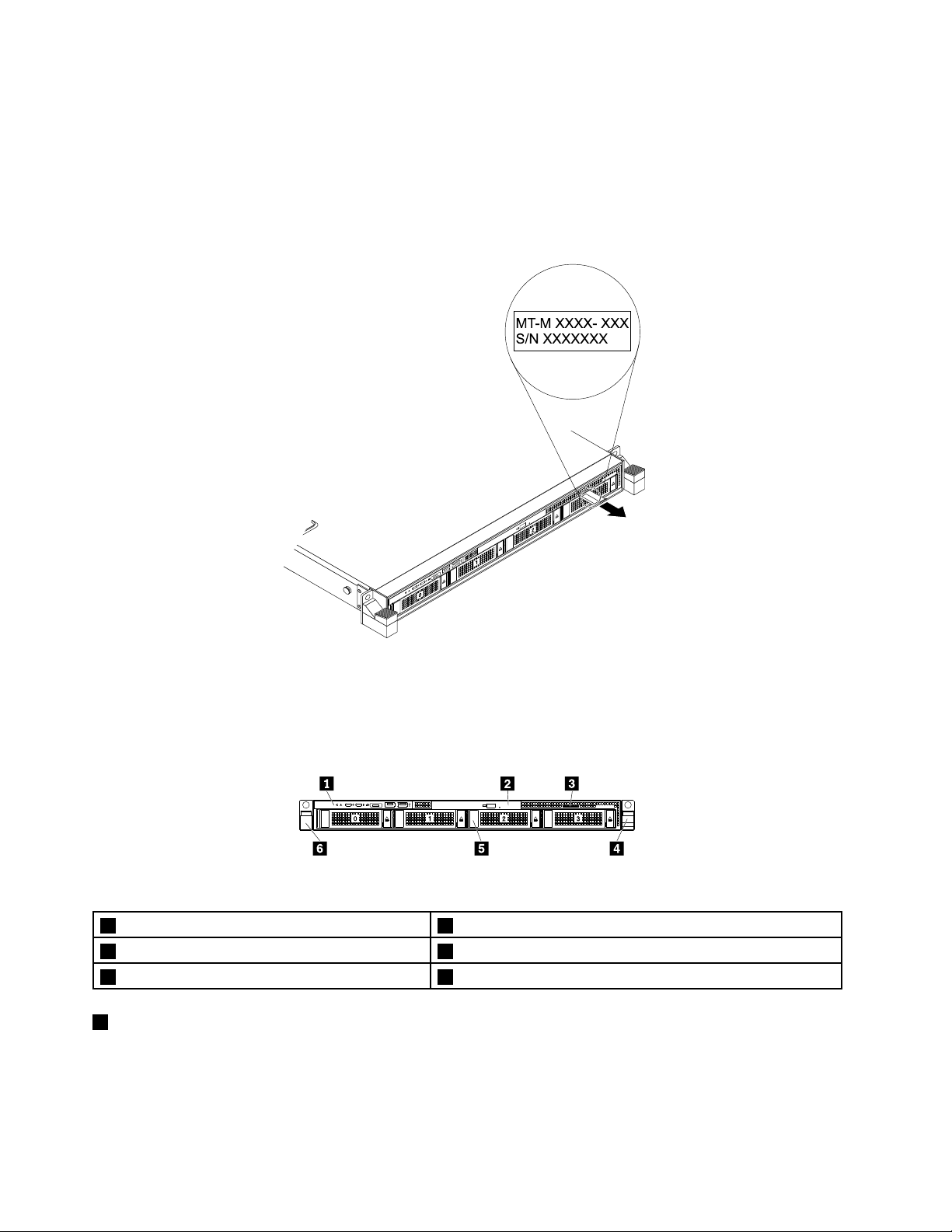
Themachinetype,model,andserialnumberlabelisattachedonthepull-outinformationcard,whichis
MT-M XXXX- XXX
S/N XXXXXXX
asmallplastictabandcanbeslidoutofthefrontofthechassis.Thefollowingillustrationsaresamples
ofthemachinetype,model,andserialnumberlabelsonstorageproductmodelswithdifferentharddisk
driveconfigurations.
Note:Dependingonthemodel,yourstorageproductmightlookslightlydifferentfromtheillustrationsin
thistopic.
Figure1.Labelonstorageproductmodelswith3.5-inch-drivebays
Frontviewofthestorageproduct
Figure2.Frontviewofthestorageproduct
1Frontpanel
3Pull-outinformationcard
53.5-inch-drivebays(0-3)6Rackhandle(left)
1Frontpanel
Fordetailedinformationaboutthecontrols,connectors,andstatusLEDsonthefrontpanel,see“Front
panel”onpage15
.
2Slimopticaldrive(availableonsomemodels)
4Rackhandle(right)
14LenovoStorageN3310UserGuideandHardwareMaintenanceManual
Page 29
2Slimopticaldrive
SomestorageproductmodelscomewithaslimSATAopticaldrive.
3Pull-outinformationcard
Themachinetype,model,andserialnumberlabelofthestorageproductisattachedonthepull-out
informationcard.See“Machinetype,model,andserialnumberlabel”onpage13.
4Rackhandle(right)
6Rackhandle(left)
Ifyourstorageproductisinstalledinarackcabinet,youcanusetherackhandlestohelpyouslidethe
storageproductoutoftherackcabinet.Y oualsocanusetherackhandlesandscrewstosecurethestorage
productintherackcabinetsothatthestorageproductcannotslideout,especiallyinvibration-proneareas.
Formoreinformation,refertotheRackInstallationInstructionsthatcomeswithyourstorageproduct.
53.5-inch-drivebays(0-3)
TheEMIintegrityandcoolingofthestorageproductareprotectedbyhavingalldrivebayscoveredor
occupied.Thenumberoftheinstalledharddiskdrivesinyourstorageproductvariesbymodel.Thevacant
hard-disk-drivebaysareoccupiedbydummyhard-disk-drivetrays.
Whenyouinstalldrives,followtheorderofthedrivebaynumbers.
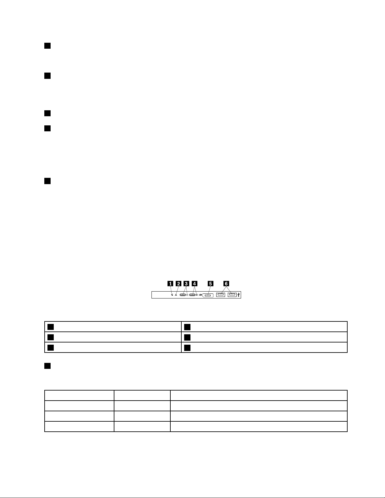
Frontpanel
Thefollowingillustrationshowsthecontrols,connectors,andLEDsonthefrontpanelofthestorage
product.Thefrontpanelvariesbymodel.
Figure3.Frontpanel
1NetworkstatusLED
3PowerbuttonwithpowerstatusLED
5DisplayPortconnector
1NetworkstatusLED
ThenetworkstatusLEDonthefrontpanelhelpsyouidentifythenetworkconnectivityandactivity.
NetworkstatusLED
OnGreen
Off
Blinking
Color
None
Green
2SystemhealthLED
4SystemIDbuttonwithIDLED
6USB2.0connectors(2)
Description
ThestorageproductisconnectedtoaLAN.
ThestorageproductisdisconnectedfromaLAN.
TheLANisconnectedandactive.
Chapter3.Productoverview15
Page 30
2SystemhealthLED
ThesystemhealthLEDhelpsyoutodetermineifthereareanysystemerrors.
•Off:Thestorageproductisofforthestorageproductisonandworkingcorrectly.
•Amber:Thestorageproducthaspotentialsystemerrors.Checktheinformationinthefollowingtablefor
potentialsystemerrorsandcorrespondingsolutions.
•Blinking:TSMinitializationisinprogress.
Potentialsystemerror(systemhealthLED:amber)Solution
Thetemperatureofthestorageproductreachedthe
non-criticaltemperaturethreshold.
Thevoltageofthestorageproductreachedthenon-critical
voltagethreshold.
Afanisrunningatlowspeed.
Asystemfanhasbeenremoved.1.Ensurethatthesystemfansareconnectedsecurely
Thepowersupplyhasacriticalerror.
Apowercordhasbeendisconnectedoraredundant
powersupplyhasbeenremoved.
Thesystemisoverheated.
ChecktheBMCforerrorsandcheckthesystemfans.
Replacethesystemboard.
Note:ThisactionmustbeperformedonlybyLenovo
servicepersonnel.SeeChapter8“Gettinginformation,
help,andservice”onpage121
Checkthesystemfans.
tothesystemboard.
2.Reinstalltheremovedfanorinstallanewfanto
replacetheremovedfan.
ChecktheBMCfordetailedinformation.
1.Ensurethatthepowersuppliesareinstalledsecurely.
2.Ensurethatthepowercordsareconnectedsecurely
tothepowersupplies.
3.Installanewpowersupplytoreplacetheremoved
one.
ChecktheBMCforerrorsandthencheckthesystem
fans.
.
3PowerbuttonwithpowerstatusLED
Youcanpressthepowerswitchtoturnonthestorageproductwhenyoufinishsettingupthestorage
product.Youalsocanholdthepowerswitchforseveralsecondstoturnoffthestorageproductifyoucannot
turnitofffromtheoperatingsystem.SeeChapter4“Turningonandturningoffthestorageproduct”on
page29
.ThepowerstatusLEDhelpsyoutodeterminethecurrentpowerstatus.
StatusColor
OnGreen
Off
None
Thestorageproductison.
Thestorageproductisoff.
Description
16LenovoStorageN3310UserGuideandHardwareMaintenanceManual
Page 31

4SystemIDbuttonwithIDLED
WhenyoupressthesystemIDbutton,theIDLEDsonboththefrontandrearofthestorageproductarelitto
helpyoulocatethestorageproductamongotherstorageproducts.YoualsocanturnontheIDLEDsusinga
remotemanagementprogramforstorageproductpresencedetection.
StatusColor
On
Off
5DisplayPortconnector
Blue
NoneTheIDLEDisnotinuseorthesystemisnot
Thesystemisidentified.
identified.
Description
Usedtoattachahigh-performancemonitor,adirect-drivemonitor,orotherdevicesthatuseaDisplayPort
connector.
6USB2.0connectors(2)
UsedtoattachaUSB-compatibledevice,suchasaUSBkeyboard,mouse,scanner,orprinter.Ifyouhave
morethanfourUSBdevices,youcanpurchaseaUSBhub,whichyoucanusetoconnectadditional
USBdevices.
Rearviewofthestorageproduct
Thistopicprovidesinformationtohelpyoulocatetheconnectorsandcomponentsontherearofyour
storageproduct.
Thefollowingillustrationshowstheconnectorsandcomponentsontherearofyourstorageproduct.The
rearviewofthestorageproductvariesbymodel.
Figure4.Rearviewofthestorageproduct
1Powersupply1
3PCIeslot24PCIeslot1
5SystemIDLED6USB3.0connectors(2)
7Ethernetconnector2(RJ-45)8Ethernetconnector1(RJ-45)
9Serialconnector10Ethernetconnectorforsystemmanagement(RJ-45)
11VGAconnector(DB-15)
2Powersupply2(availableonsomemodels)
Chapter3.Productoverview17
Page 32

1Powersupply1
2Powersupply2(availableonsomemodels)
Thehot-swapredundantpowersupplieshelpyouavoidsignificantinterruptiontotheoperationofthe
systemwhenapowersupplyfails.YoucanpurchaseapowersupplyoptionfromLenovoandinstallthe
powersupplytoprovidepowerredundancywithoutturningoffthestorageproduct.
Oneachpowersupply,therearethreestatusLEDsnearthepowercordconnector.Forinformationabout
thestatusLEDs,see“PowersupplystatusLEDs”onpage28.
3PCIeslot2
ItisrecommendedthatyouattachaRAIDcardtothelow-profilePCIeslot.
PhysicallinkwidthNegotiablelinkwidth
x16x16,x8,x4,x2,x1
4PCIeslot1
Supportedcardlengthandheight
Low-profilecard
UsedtoattachanEthernetcardoranyothersupportedPCIecard.
PhysicallinkwidthNegotiablelinkwidth
x16x16,x8,x4,x2,x1
5SystemIDLED
Supportedcardlengthandheight
Half-length,full-heightcard
WhenyoupresstheIDbuttononthefrontpanel,theIDLEDsonboththefrontandrearofthestorage
productarelittohelpyoulocatethestorageproductamongotherstorageproducts.Youalsocanturnon
theIDLEDsusingaremotemanagementprogramforstorageproductpresencedetection.
StatusColor
On
Off
6USB3.0connectors(2)
Blue
NoneTheIDLEDisnotinuseorthesystemisnot
Thesystemisidentified.
identified.
Description
UsedtoattachaUSB-compatibledevice,suchasaUSBkeyboard,mouse,scanner,orprinter.Ifyouhave
morethanfourUSBdevices,youcanpurchaseaUSBhub,whichyoucanusetoconnectadditional
USBdevices.
7810Ethernetconnectors(RJ-45)
UsedtoattachanEthernetcableforaLAN.EachEthernetconnectorhastwostatusLEDstohelpyou
identifytheEthernetconnectivity,activity,andconnectionspeed.
Note:Ethernetconnector0(callout
10)markedwith“MGMT”isforsystemmanagementbydefault.
18LenovoStorageN3310UserGuideandHardwareMaintenanceManual
Page 33

EthernetstatusLED
1Left
2Right
9Serialconnector
ColorStatus
Amber
GreenOn
None
GreenOn
None
Green
On
Off
Off
BlinkingTheLANisconnectedandactive.
Theconnectionspeedis1000Mbps.
Theconnectionspeedis100Mbps.
Theconnectionspeedis10Mbps.
ThestorageproductisconnectedtoaLAN.
Thestorageproductisdisconnectedfroma
LAN.
Description
Usedtoattachadevicethatusesa9-pinserialconnector.
11VGAconnector(DB-15)
UsedtoattachaVGA-compatiblevideodevice,suchasaVGAmonitor.
Storageproductcomponents
Thistopicprovidesinformationtohelpyoulocatethecomponentsofyourstorageproduct.Formore
informationaboutmajorcomponents,seetherelatedtopicsin“Locations”onpage13.
Toremovethestorageproductcoverandthecoolingshroudandgainaccesstotheinsideofthestorage
product,see“Removingthecover”onpage43and“Removingandreinstallingthecoolingshroud”
onpage46.
Thechassisconfigurationvariesbymodel.
Note:Dependingonthemodel,yourstorageproductmightlookslightlydifferentfromtheillustrationsin
thistopic.
Chapter3.Productoverview19
Page 34

Figure5.Storageproductcomponents
1Oneortwohot-swapredundantpowersupplies2DIMMs(varybymodel)
3Systemboard4Coolingshroud
5Backplanefor3.5-inchdrives
7Rackhandle(right)
9Rackhandle(left)10Slimopticaldrive(availableonsomemodels)
11Systemfans12Heatsink(s)withmicroprocessor(s)underneath
13Risercardassembly114Risercardassembly2
6ThinkServerRAIDSuperCapacitorModule(availableon
somemodels)
83.5-inch-drivearea
CRUsarepartsthatcanbeupgradedorreplacedbythecustomer.IfaCRUisdeterminedtobedefective
duringthewarrantyperiod,areplacementCRUwillbeprovidedtothecustomer.Customersareresponsible
forinstallingtheself-serviceCRUsforthisproduct.Customersalsocaninstalloptional-serviceCRUs,which
mightrequiresometechnicalskillsortools,orrequestthatatechnicianinstalltheoptional-serviceCRU
underthetermsoftheapplicablewarrantyservicetypeforyourcountryorregion.
Non-CRUsmustbereplacedonlybytrainedservicetechnicians.
ThefollowingtableliststhemajorFRUsinyourstorageproductandtheCRUidentificationinformation.For
acompletelistingofFRUinformation,suchasFRUpartnumbersandsupportedstorageproductmodels,
goto:
http://www.lenovo.com/serviceparts-lookup
Notes:
•BeforeservicingaLenovoproduct,ensurethatyoureadandunderstand“Safetyinformation”onpageiii.
•UseonlypartsprovidedbyLenovo.
*Availableonsomemodels
20LenovoStorageN3310UserGuideandHardwareMaintenanceManual
Page 35

FRUdescription
Coin-cellbattery
Coolingshroud
FrontbackplaneNoYes
FrontpanelboardYesNo
HeatsinkYesNo
Hot-swapstoragedrive*YesNo
Hot-swapredundantpowersupplyYesNo
Intrusionswitch*YesNo
MemorymoduleYesNo
MicroprocessorNoYes
PCIecard
PowercordYesNo
RackhandlesYesNo
RisercardYesNo
Slimopticaldrive*
Systemboard
Systemfan
ThinkServeropticalmodule*
ThinkServerRAID110iupgradekey*
ThinkServerRAIDSuperCapacitorModule*
ThinkServerRAIDSuperCapacitorModuleholder*
ThinkServerSystemManagerPremiummodule*
Self-serviceCRUOptional-serviceCRU
YesNo
YesNo
YesNo
YesNo
NoNo
YesNo
YesNo
YesNo
YesNo
YesNo
YesNo
ThinkServerRAID710Adapter
SomestorageproductmodelscomewithaRAIDcardtoprovideadvancedSATA/SAShardwareRAID
functionstothestorageproduct.ThistopicprovidesinformationtohelpyoulocatetheconnectorsonaRAID
card.IfyourstorageproducthasaRAIDcardinstalled,theRAIDcardisseatedontherisercardassembly2.
Note:TheoptionkitfortheRAIDcardisdesignedfordifferenttypesofstorageproductsandmightcontain
additionalcablesthatarenotrequiredforyourstorageproduct.
Chapter3.Productoverview21
Page 36

ThefollowingillustrationshowstheconnectorsontheThinkServerRAID710Adapter.
Figure6.ThinkServerRAID710Adapter
1Port1
Usedtoconnectamini-SASsignalcabletothemini-SASports0-3onthebackplane.
2ThinkServerRAIDSuperCapacitorModuleconnector
UsedtoconnectthecableofaThinkServerRAIDSuperCapacitorModule.
ToinstallorremovetheRAIDcard,referto“InstallingorremovingaPCIecard”onpage62.
Hot-swap-drivebackplane
Thefollowingillustrationsshowtheslotsandconnectorsonthebackplanefor3.5-inchdrives.
Figure7.Frontviewofthebackplanefor3.5-inchdrives
Figure8.Rearviewofthebackplanefor3.5-inchdrives
0-3Slot0-slot3
Usedtoconnect3.5-inchdrives.
410-pinpowerconnector
Usedtoconnecttothebackplanepowerconnectoronthesystemboardtoprovidepowertothebackplane.
5Opticaldrivepowerconnector
22LenovoStorageN3310UserGuideandHardwareMaintenanceManual
Page 37

Usedtoconnectthepowercablefortheslimopticaldrive.
6Mini-SASports0-3
Usedtoconnectthemini-SASconnectorononeendofamini-SAStomini-SASsignalcabletosupportthe
harddiskdrive0toharddiskdrive3.
Systemboardcomponents
Thefollowingillustrationshowsthecomponentlocationsonthesystemboard.
Figure9.Systemboardcomponents
1SATAconnector(opticaldrive)2Coin-cellbattery
3SATAconnector0(ports0–3)
5Frontpanelconnector26Risercardassembly1slot
7TSMPremiummoduleconnector8PCIeslot
9Risercardassembly2slot10RAIDupgradekeyconnector
11Powersupplyconnector212Powersupplyconnector1
13Intrusionswitchconnector14Backplanepowerconnector2
15Backplanepowerconnector1
17Microprocessor2memoryslots(4)18Systemfan5connector
19Microprocessor2socket
21Microprocessor2memoryslots(4)22Microprocessor1memoryslots(4)
23Systemfan3connector24Systemfan2connector
4Frontpanelconnector1
16Systemfan6connector
20Systemfan4connector
Chapter3.Productoverview23
Page 38

25Microprocessor1socket
27Microprocessor1memoryslots(4)
1SA TAconnector(opticaldrive)
26Systemfan1connector
Usedtoconnectthesignalcableoftheslimopticaldrive.
2Coin-cellbattery
Yourstorageproducthasaspecialtypeofmemorythatmaintainsthedate,time,andconfiguration
informationforbuilt-infeatures.Thecoin-cellbatterykeepstheinformationactivewhenyouturnoffthe
storageproduct.
3SA TAconnector0(ports0–3)
UsedtoconnecttotheMini-SASports0-3onthebackplane.
45Frontpanelconnector
Usedtoconnecttothefrontpanelboard.
6Risercardassembly1slot
Usedtoinstalltherisercardassembly1.
7TSMPremiummoduleconnector
UsedtoconnectaTSMPremiummoduletoenableadvancedremotemanagementfunctionsonyour
storageproduct.
8PCIeslot
UsedtoinstallasupportedPCIecard.ForinformationaboutsupportedPCIecards,see“Rearviewofthe
storageproduct”onpage17
9Risercardassembly2slot
.
Usedtoinstalltherisercardassembly2.
10RAIDupgradekeyconnector
UsedtoconnectaThinkServerRAID110iupgradekey.
11Powersupplyconnector2
Usedtoconnectthepowersupply2.
12Powersupplyconnector1
Usedtoconnectthepowersupply1.
13Intrusionswitchconnector
Usedtoconnecttoanintrusionswitch.
24LenovoStorageN3310UserGuideandHardwareMaintenanceManual
Page 39

1415Backplanepowerconnector
Usedtoconnecttothe10-pinpowerconnectoronthebackplane.
161820232426Systemfanconnector
Usedtoconnectasystemfan.
17212227Memoryslots
Thereare16memoryslotsonthesystemboard.Fordetailedinformation,see“Memorymoduleinstallation
rules”onpage48.
19Microprocessor2socket
25Microprocessor1socket
Ifthestorageproducthastwomicroprocessors,eachofthemicroprocessorissecuredinthemicroprocessor
socketonthesystemboardandaheatsinkisinstalledabovethemicroprocessortoprovidecooling.Ifthe
storageproducthasonlyonemicroprocessor,themicroprocessorsocket2isprotectedbyamicroprocessor
socketcover.
Systemboardjumpers
Thefollowingillustrationshowsthejumpersonthesystemboardofyourstorageproduct.
Figure10.Systemboardjumpers
1Jumpercapstorage
3BIOSdefaultsettingsjumper4Clearpasswordjumper
2BIOSrecoveryjumper
Attention:Tosetthejumpers,removethestorageproductcoverandgainaccesstothesystemboard
first.Donotopenyourstorageproductorattemptanyrepairbeforereadingandunderstanding“Safety
information”onpageiiiand“Guidelines”onpage41.
Chapter3.Productoverview25
Page 40

1Jumpercapstorage
Usedtostorethejumpercap.Ajumpercapisencasedonthepinsbydefault.
2BIOSrecoveryjumper
UsedtorecovertheBIOSifthepowertoyourstorageproductisinterruptedwhiletheBIOSisbeingupdated
andyourstorageproductcannotstartcorrectly.
TorecovertheBIOS,see“RecoveringfromaBIOSupdatefailure”onpage37
3BIOSdefaultsettingsjumper
.
UsedtoturntheBIOSsettingsintothefactory-defaultsettings.
ToturntheBIOSsettingsintothefactory-defaultsettings,dothefollowing:
1.Removeallexternalmediafromthedrivesandturnoffallattacheddevicesandthestorageproduct.
Then,disconnectallpowercordsfromelectricaloutletsanddisconnectallcablesthatareconnectedto
thestorageproduct.
2.Prepareyourstorageproduct.See“Removingorextendingthestorageproductfromtherackcabinet”
onpage43
.
3.Removethestorageproductcover.See“Removingthecover”onpage43.
4.LocatetheBIOSdefaultsettingsjumper3onthesystemboard.Then,removeanypartsand
disconnectanycablesthatmightimpedeyouraccesstothejumper.
Note:Donotremovethememorymodulesormicroprocessors.
5.Removethejumpercapfromthejumpercapstorage1.
6.NotetheorientationofthejumpercapandtheninstallthejumpercapontheBIOSdefaultsettings
jumper.
7.Reinstallanypartsandreconnectanycables.Then,reinstallthestorageproductcover.See
“Completingthepartsreplacement”onpage112.
8.Connectthestorageproducttoanacpowersourceandwaitforseveralminutes.Then,turnonthe
storageproduct.TheBIOSsettingsturnintothefactory-defaultsettings.
9.Repeatstep1throughstep3.
10.Movethejumpercapbacktothejumpercapstorage1.
11.Reinstallanypartsandreconnectanycables.Then,reinstallthestorageproductcover.See
“Completingthepartsreplacement”onpage112.
12.Connectthestorageproducttoanacpowersourceandturnonthestorageproduct.
4Clearpasswordjumper
Usedtoeraseforgottenpasswords,suchastheBIOSpasswords.
Toclearpasswords,dothefollowing:
1.Removeallexternalmediafromthedrivesandturnoffallattacheddevicesandthestorageproduct.
Then,disconnectallpowercordsfromelectricaloutletsanddisconnectallcablesthatareconnectedto
thestorageproduct.
2.Prepareyourstorageproduct.See“Removingorextendingthestorageproductfromtherackcabinet”
onpage43.
3.Removethestorageproductcover.See“Removingthecover”onpage43.
26LenovoStorageN3310UserGuideandHardwareMaintenanceManual
Page 41

4.Locatetheclearpasswordjumper4onthesystemboard.Then,removeanypartsanddisconnectany
cablesthatmightimpedeyouraccesstothejumper.
Note:Donotremovethememorymodulesormicroprocessors.
5.Removethejumpercapfromthejumpercapstorage1.
6.Notetheorientationofthejumpercapandtheninstallthejumpercapontheclearpasswordjumper.
7.Reinstallanypartsandreconnectanycables.Then,reinstallthestorageproductcover.See
“Completingthepartsreplacement”onpage112.
8.Connectthestorageproducttoanacpowersourceandwaitforseveralminutes.Then,turnonthe
storageproduct.TheBIOSpasswordsareerased,includingtheadministratorpasswordanduser
password.
9.Repeatstep1throughstep3.
10.Movethejumpercapbacktothejumpercapstorage1.
11.Reinstallanypartsandreconnectanycables.Then,reinstallthestorageproductcover.See
“Completingthepartsreplacement”onpage112.
12.Connectthestorageproducttoanacpowersourceandturnonthestorageproduct.
13.Tosetnewpasswords,see“Usingpasswords”onpage34.
Hot-swap-drivestatusLEDs
Eachhot-swapdrivehastwostatusLEDsonthefront.
Figure11.Hot-swap-drivestatusLEDs
1DriveactivityLED2DrivestatusLEDDescription
OffOff
On,greenOff
Blinking,green
On,greenBlinkingrapidly(aboutfourflashes
On,greenOn,amber
Blinking,green
Off
persecond),amber
Blinkingslowly(aboutoneflashper
second),amber
Thedrivehasfailedorisnotpresent.
Thedriveispresentbutnotinuse.
Thedriveisactiveanddataisbeing
transferred.
TheRAIDcontrollerisidentifyingthe
drive.
TheRAIDarrayhasfailedandcannot
berecovered.Youneedtorecreatea
newarray.
Thedriveisbeingrebuilt.
Chapter3.Productoverview27
Page 42

PowersupplystatusLEDs
1
2
3
Eachhot-swappowersupplyhasthreestatusLEDs.
Figure12.PowersupplystatusLEDs
LED
1InputstatusLED
2Outputstatus
LED
3FaultLED
Status
Off
On,green
Off
Blinking,green(aboutone
flasheverytwoseconds)
Blinking,green(abouttwo
flasheseachsecond)
On,green
Off
On,amber
DescriptionAction
Thepowersupplyis
disconnectedfromtheac
powersource.
Thepowersupplyisconnected
totheacpowersource.
Thestorageproductisoffor
thepowersupplyisnotworking
normally.
Thepowersupplyisincold
redundancyactivemode.
Thepowersupplyisincold
redundancysleepmode.
Thestorageproductisonand
thepowersupplyisworking
normally.
Thepowersupplyisworking
normally.
Thepowersupplyhasfailed.
Noactionisneeded.
Noactionisneeded.
Replacethepowersupply.
See“Installingorreplacinga
hot-swapredundantpower
supply”onpage83
Noactionisneeded.
Noactionisneeded.
Noactionisneeded.
Noactionisneeded.
Replacethepowersupply.
See“Installingorreplacinga
hot-swapredundantpower
supply”onpage83
.
.
Connectingthecables
Toconnectthesignalcablesfromtheinstalledhardwarecomponents,refertotherelatedinformation
inthefollowingtopics:
•“Hot-swap-drivebackplane”onpage22
•“ThinkServerRAID710Adapter”onpage21
•“Systemboardcomponents”onpage23
28LenovoStorageN3310UserGuideandHardwareMaintenanceManual
Page 43

Chapter4.Turningonandturningoffthestorageproduct
Thischapterprovidesinformationaboutturningonandturningoffthestorageproduct.
Turningonthestorageproduct
Thestorageproductcanbeturnedoninoneofthefollowingways:
•Afteryoufinishunpackingandsettingupthestorageproduct,connectittoanacpowersource.Press
thepowerbuttononthefrontpaneltoturnonthestorageproduct.See“Frontpanel”onpage15
storageproductneedsabout30secondsfortheThinkServerSystemManager(TSM,alsoknownas
BMC)toinitializewheneveryouconnectthestorageproducttoanacpowersource.Ifyoupressthe
powerbuttononthefrontpanelduringthisperiod,thestorageproductwillnotstartimmediately;itwill
startaftertheTSMinitializationfinishes.
•WhentheWakeonLANfeatureisenabledonthestorageproductthatisconnectedtoanacpower
sourceandaLAN,anetworkadministratorcanremotelyturnonorwakeupthestorageproductfroma
managementconsoleusingremotenetworkmanagementsoftware.
•YoualsocanusetherelatedTSMfeaturetoremotelyturnonthestorageproductthroughthe
managementLAN.
Turningoffthestorageproduct
CAUTION:
Thepowercontrolbuttononthedeviceandthepowerswitchonthepowersupplydonotturnoff
theelectricalcurrentsuppliedtothedevice.Thedevicealsomighthavemorethanonepower
cord.T oremoveallelectricalcurrentfromthedevice,ensurethatallpowercordsaredisconnected
fromthepowersource.
.The
Thestorageproductcanbeturnedoffinoneofthefollowingways:
•Turnoffthestorageproductfromtheoperatingsystemifyouroperatingsystemsupportsthisfeature.
Afteranorderlyshutdownoftheoperatingsystem,thestorageproductwillturnoffautomatically.For
instructionsonhowtoshutdownyourspecificoperatingsystem,refertotherelateddocumentationor
helpsystemfortheoperatingsystem.
•Pressthepowerswitchonthefrontpaneltostartanorderlyshutdownoftheoperatingsystemandturn
offthestorageproduct,ifyouroperatingsystemsupportsthisfeature.
•Ifyourstorageproductstopsrespondingandyoucannotturnitoff,pressandholdthepowerswitchon
thefrontpanelforfoursecondsormore.Ifyoustillcannotturnoffthestorageproduct,disconnectall
powercordsfromthestorageproduct.
•IfthestorageproductisconnectedtoaLAN,anetworkadministratorcanremotelyturnoffthestorage
productfromamanagementconsoleusingremotenetworkmanagementsoftware.
•YoualsocanusetherelatedTSMfeaturetoremotelyturnoffthestorageproductthroughthe
managementLAN.
•Thestorageproductmightbeturnedoffasanautomaticresponsetoacriticalsystemfailure.
Notes:
©CopyrightLenovo2015
29
Page 44

•Whenyouturnoffthestorageproductandleaveitconnectedtoanacpowersource,thestorageproduct
alsocanrespondtoaremoterequesttoturnonthestorageproduct.Toremoveallpowerfromthe
storageproduct,youmustdisconnectthestorageproductfromtheacpowersource.
•Forinformationaboutyourspecificoperatingsystem,refertotherelateddocumentationorhelpsystem
fortheoperatingsystem.
30LenovoStorageN3310UserGuideandHardwareMaintenanceManual
Page 45

Chapter5.Configuringthestorageproduct
Thischapterprovidesthefollowinginformationtohelpyouconfigurethestorageproduct:
•“UsingtheSetupUtilityprogram”onpage31
•“ConfiguringRAID”onpage38
•“Updatingthefirmware”onpage40
UsingtheSetupUtilityprogram
ThistopicprovidesinformationaboutusingtheSetupUtilityprogram.
TheSetupUtilityprogramispartofthestorageproductfirmware.Y oucanusetheSetupUtilityprogram
toviewandchangetheconfigurationsettingsofyourstorageproduct,regardlessofwhichoperating
systemyouareusing.However,theoperatingsystemsettingsmightoverrideanysimilarsettingsinthe
SetupUtilityprogram.
StartingtheSetupUtilityprogram
ThistopicprovidesinstructionsonhowtostarttheSetupUtilityprogram.
TostarttheSetupUtilityprogram,dothefollowing:
1.Connectthestorageproducttoanacpowersourceandpressthepowerswitchonthefrontpanelto
turnonthestorageproduct.See“T urningonthestorageproduct”onpage29.
2.PresstheF1keyassoonasyouseethescreen.Then,waitforseveralseconds,andtheSetupUtility
programopens.Ifyouhavesetapassword,typethecorrectpasswordtoentertheSetupUtility
program.Forpasswordinformation,see“Usingpasswords”onpage34
.
ViewinginformationintheSetupUtilityprogram
TheSetupUtilityprogrammenulistsvariousitemsaboutthesystemconfiguration.Selectadesireditem
toviewinformationorchangesettings.
WhenworkingwiththeSetupUtilityprogram,youmustusethekeyboard.Thekeysusedtoperformvarious
tasksaredisplayedontherightbottompaneofeachscreen.Y oualsocanpresstheF1keyforgeneralhelp
aboutthekeys.Formostitems,thecorrespondinghelpmessageisdisplayedontherighttoppaneofthe
screenwhentheitemisselected.Iftheitemhassubmenus,youcandisplaythesubmenusbypressingEnter.
SetupUtilityprograminterface
DependingontheBIOSversionofyourstorageproduct,somemenuoriteminformationmightdifferslightly
fromtheinformationinthistopic.
Notes:
•Thedefaultsettingsalreadyareoptimizedforyou.Usethedefaultvalueforanyitemyouarenotfamiliar
with.Donotchangethevalueofunfamiliaritemstoavoidunexpectedproblems.Ifyouconsiderchanging
thestorageproductconfiguration,proceedwithextremecaution.Settingtheconfigurationincorrectly
mightcauseunexpectedresults.IfyoucannotturnonthestorageproductbecauseofincorrectBIOS
settings,usetheBIOSdefaultsettingsjumpertorestoretheBIOSsettingstothefactorydefaultsettings.
See“Systemboardjumpers”onpage25
.
©CopyrightLenovo2015
31
Page 46

•Ifyouhavechangedanyhardwareinthestorageproduct,youmightneedtoupgradetheBIOSand
theTSMfirmware.
TheSetupUtilityprogrammaininterfaceconsistsofthefollowingmenus:
•“SystemInformationmenu”onpage32
•“AdvancedSettingsmenu”onpage32
•“SystemSecuritymenu”onpage33
•“TSMSettingsmenu”onpage33
•“BootManagermenu”onpage33
•“Save&Exitmenu”onpage33
LenovoprovidestheBIOSupdateutilityontheLenovoSupportWebsite.YoucandownloadtheBIOS
updateutilitytoupdatetheBIOS.See“UpdatingorrecoveringtheBIOS”onpage36
IfthepowertoyourstorageproductisinterruptedwhiletheBIOSisbeingupdatedandyourstorageproduct
cannotstartcorrectly,theBIOSwillrecovertothepreviousversionautomatically.Therecoveryprocess
lastsabout20minutes.YoualsocanusetheBIOSrecoveryjumpertorecoverfromaBIOSupdatefailure.
See“Systemboardjumpers”onpage25.
.
SystemInformationmenu
AfterenteringtheSetupUtilityprogram,youcanseetheSystemInformationmenu,whichlistsbasic
informationabouttheBIOS,microprocessortype,memory,systemdateandtime,andsoon.
TosetthesystemdateandtimeontheSystemInformationmenu,see“Settingthesystemdateand
time”onpage34.
AdvancedSettingsmenu
YoucanvieworchangevariousstorageproductcomponentsettingsontheAdvancedSettingsmenuinthe
SetupUtilityprogram.TheAdvancedSettingsmenucontainsvariousconfigurationsubmenusanditems.
Oneachsubmenu,pressEntertoshowselectableoptionsandselectadesiredoptionbyusingtheupand
downarrowkeysortypedesiredvaluesfromthekeyboard.Someitemsaredisplayedonthemenuonlyif
thestorageproductsupportsthecorrespondingfeatures.
Notes:
•Enabledmeansthatthefunctionisconfigured.
•Disabledmeansthatthefunctionisnotconfigured.
TheAdvancedSettingsmenucontainsthefollowingsubmenus.Formoreinformation,enterthe
correspondingsubmenuandrefertotheinstructionsonthescreen.
•ProcessorSettings:Viewinformationabouttheinstalledmicroprocessorsandsetmicroprocessor
configurationparameters.
•MemorySettings:Viewinformationabouttheinstalledmemorymodulesandsetmemoryconfiguration
parameters.
•AdvancedPowerSettings:Viewandsetpowerandperformanceparameters.
•PCI/PCIESettings:ViewandsetPCIorPCIeconfigurationparameters.
•SATASettings:SetonboardSATAparameters.
•USBSettings:ViewandsetUSBconfigurationparameters,suchasenablingordisablingUSBdevices.
•SerialSettings:Viewandsetconfigurationparametersfortheserialconnector.
32LenovoStorageN3310UserGuideandHardwareMaintenanceManual
Page 47

•WakeupSettings:Viewandconfigurethewakeuptimingandsetthepowerstateafterapowerfailure.
•MiscellaneousSettings:Viewandconfiguresomemiscellaneousitems,suchastheNumLockkeyon
thekeyboardandthebootstatuscode.
SystemSecuritymenu
YoucansetpasswordsandconfiguretheTPMfunctionontheSystemSecuritymenuintheSetupUtility
program.Foreachmenuitem,pressEntertoshowselectableoptionsandselectadesiredoptionbyusing
theupanddownarrowkeysortypedesiredvaluesfromthekeyboard.Someitemsaredisplayedonthe
menuonlyifthestorageproductsupportsthecorrespondingfeatures.
Notes:
•Enabledmeansthatthefunctionisconfigured.
•Disabledmeansthatthefunctionisnotconfigured.
TheSystemSecuritymenucontainsthefollowingitems:
•AdministratorPassword:Setanadministratorpasswordtoprotectagainstunauthorizedaccesstoyour
storageproduct.See“Usingpasswords”onpage34
•UserPassword:Setauserpasswordtoprotectagainstunauthorizedaccesstoyourstorageproduct.
See“Usingpasswords”onpage34.
•SecureBoot:Setsecurebootparameters.
.
TSMSettingsmenu
YoucanvieworchangeeventlogandBMCsettingsontheTSMSettingsmenuintheSetupUtilityprogram.
Oneachsubmenu,pressEntertoviewtheinformationorshowselectableoptionsandselectadesired
optionbyusingtheupanddownarrowkeys.Someitemsaredisplayedonthemenuonlyifthestorage
productsupportsthecorrespondingfeatures.
TheTSMSettingsmenucontainsthefollowingsubmenus.Formoreinformation,enterthecorresponding
submenuandrefertotheinstructionsonthescreen.
•TSMNetworkSettings:SetBMCmanagementnetworkconfigurationparameters.
•UserAccountSettings:SetBMCuseraccountparameters.
BootManagermenu
TheBootManagermenuintheSetupUtilityprogramlistsallthebootabledevicesinstalledinyourstorage
productandthelisteditemsvarydependingonyourstorageproductconfiguration.
TheBootSequencesubmenuintheBootManagermenuprovidesaninterfacetohelpyouvieworchange
thestorageproductstartupoptions,includingthestartupsequenceandbootpriorityforvariousdevices.
Changesinthestartupoptionstakeeffectwhenthestorageproductrestarts.Thestartupsequencespecifies
theorderinwhichthestorageproductchecksdevicestofindabootrecord.Thestorageproductstartsfrom
thefirstbootrecordthatitfinds.Forexample,youcandefineastartupsequencethatchecksadiscinthe
opticaldrive,thencheckstheinternalstoragedrive,andthenchecksanetworkdevice.Forinformationabout
settingthestartupsequenceorselectingastartupdevice,see“Selectingastartupdevice”onpage35
Save&Exitmenu
AfteryoufinishviewingorchangingsettingsintheSetupUtilityprogram,youcanchooseadesired
actionfromtheSave&Exitmenutosavechanges,discardchanges,orloaddefaultvalues,andexitthe
program.PressEntertoselecttheitemontheSave&Exitmenu,andthenselectYeswhenpromptedto
confirmtheaction.ForinformationaboutexitingtheSetupUtilityprogram,see“ExitingtheSetupUtility
program”onpage36.
.
Chapter5.Configuringthestorageproduct33
Page 48

TheSave&Exitmenucontainsthefollowingitems:
•SaveChangesandReset:SavechangesandthencontinuewithfurtherconfigurationintheSetup
Utilityprogram.
•DiscardChangesandExit:Discardchanges,loadpreviousvalues,andthenexittheSetupUtility
program.
•LoadOptimizedDefaults:Returntotheoptimizeddefaultsettings.
•SaveasUserDefaults:Savethecurrentsettingsasuserdefaultvalues.
•RestoreUserDefaults:Restoretheuserdefaultvaluesforalltheitems.
•PureUEFIOSOptimizedDefaults:EnableordisableoptimizeddefaultsettingsforthepureUEFI
operatingsystem.
Settingthesystemdateandtime
TosetthesystemdateandtimeintheSetupUtilityprogram,dothefollowing:
1.StarttheSetupUtilityprogram.See“StartingtheSetupUtilityprogram”onpage31.
2.OntheSystemInformationmenu,selectSystemDateorSystemTime.
3.UsetheTabkeytoswitchbetweendataelementsandtypethenumbersfromthekeyboardtosetthe
systemdateandtime.
4.PressF10tosavesettingsandexittheSetupUtilityprogram.
Usingpasswords
ByusingtheSetupUtilityprogram,youcansetapasswordtopreventunauthorizedaccesstoyour
storageproduct.
Youdonothavetosetapasswordtouseyourstorageproduct.However,usingapasswordimproves
computingsecurity.Ifyoudecidetosetapassword,readthefollowingtopics.
SetupUtilityprogrampasswordtypes
ThefollowingtypesofpasswordsareavailableintheSetupUtilityprogram:
•Administratorpassword
Settinganadministratorpassworddetersunauthorizedusersfromchangingconfigurationsettings.Ifyou
areresponsibleformaintainingtheconfigurationsettingsofseveralcomputers,youmightwanttoset
anadministratorpassword.Whenanadministratorpasswordisset,youarepromptedtotypeavalid
passwordeachtimeyoutrytoaccesstheSetupUtilityprogram.TheSetupUtilityprogramcannot
beaccesseduntilavalidpasswordistypedin.
•Userpassword
Whenauserpasswordisset,youarepromptedtotypeavalidpasswordeachtimethestorageproduct
turnson.Youcannotlogintoanyoperatingsystemuntilavalidpasswordistypedin.
Note:Ifboththeadministratorpasswordanduserpasswordareset,youcantypeeitherpasswordtousethe
storageproduct.However,youmustuseyouradministratorpasswordtochangeanyconfigurationsettings.
Passwordconsiderations
Forsecurityreasons,itisrecommendedtouseastrongpasswordthatcannotbeeasilycompromised.
Notes:
•TheSetupUtilityprogrampasswordsarenotcasesensitive.
•ThestorageproductsupportsSetupUtilityprogrampasswordsthatconsistofthreeto32characters.
34LenovoStorageN3310UserGuideandHardwareMaintenanceManual
Page 49

Tosetastrongpassword,usethefollowingguidelines:
•Haveatleasteightcharactersinlength
•Containatleastonealphabeticcharacterandonenumericcharacter
•Notbeyournameoryourusername
•Notbeacommonwordoracommonname
•Besignificantlydifferentfromyourpreviouspasswords
Besidesthealphabeticcharacters(a-z)andnumericcharacters(0-9),thestorageproductalsosupports
characterstypedusingspecialkeysonthekeyboardforapassword.Refertothehelpmessageonthe
screenwhensettingapasswordtodeterminethevalidspecialcharacters.
Setting,changing,ordeletingapassword
Toset,change,ordeleteapasswordintheSetupUtilityprogram,dothefollowing:
1.StarttheSetupUtilityprogram.See“StartingtheSetupUtilityprogram”onpage31.
2.OntheSystemSecuritymenu,selectAdministratorPasswordtosetanadministratorpasswordor
selectUserPasswordtosetauserpassword.
3.See“Passwordconsiderations”onpage34.Then,followtheinstructionsonthescreentosetor
changeapassword.
4.Ifyouwanttodeleteapassword,typeyourcurrentpassword.PressEnterwhenyouareprompted
totypeanewpassword.Then,pressEntertoconfirmthenewpassword.Thepreviouspassword
willbecleared.
Note:Forsecurityreasons,itisrecommendedthatyoualwayssetapasswordforyourstorageproduct.
5.PressF10tosavesettingsandexittheSetupUtilityprogram.
Ifyouhaveforgottenthepassword,youcanusetheclearpasswordjumperonthesystemboardtoerase
thepassword.See“Systemboardjumpers”onpage25.Then,setanewpasswordforthestorageproduct.
Selectingastartupdevice
Ifyourstorageproductdoesnotstartupfromadesireddevicesuchasthediscorstoragedriveas
expected,dooneofthefollowingtoselectthestartupdeviceyouwant.
Note:Notalldiscs,storagedrives,orotherremovabledevicesarebootable.
•Toselectatemporarystartupdevice,dothefollowing:
Note:Selectingastartupdeviceusingthefollowingmethoddoesnotpermanentlychangethestartup
sequence.
1.Turnonorrestartyourstorageproduct.
2.Whenyouseethelogoscreen,pressF11ifyourstorageproductisconnectedtoanetworkandyou
wanttostartupthestorageproductfromthenetwork.Otherwise,pressF12todisplaytheboot
menu.Thebootdeviceselectionwindowopens.
3.Inthebootdeviceselectionwindow,usetheupanddownarrowkeysonthekeyboardtoswitch
betweentheselections.PressEntertoselectthedeviceofyourchoice.Then,thestorageproduct
willstartupfromtheselecteddevice.
•Tovieworpermanentlychangetheconfiguredstartupdevicesequence,dothefollowing:
1.StarttheSetupUtilityprogram.See“StartingtheSetupUtilityprogram”onpage31.
Chapter5.Configuringthestorageproduct35
Page 50

2.OntheBootSequencesubmenuundertheBootManagermenu,followtheinstructionsonthe
screentosetthestartupdeviceforBootOption#1toBootOption#5dependingonyourneeds.
Youalsocansetthebootpriorityforvariousdevices.See“BootManagermenu”onpage33
3.PressF10tosavesettingsandexittheSetupUtilityprogram.Thestorageproductwillfollowthe
startupdevicesequenceyouhaveseteachtimeyouturnonthestorageproduct.
.
SettinganEthernetconnectorforsystemmanagement
TherearethreeRJ-45Ethernetconnectorsontherearofthestorageproduct.TheEthernetconnector0isfor
systemmanagementbydefault.However,youalsocansettheEthernetconnector1forsystemmanagement
use.TolocatethethreeEthernetconnectors,see“Rearviewofthestorageproduct”onpage17.
TosettheEthernetconnectorforsystemmanagement,dothefollowing:
1.StarttheSetupUtilityprogram.See“StartingtheSetupUtilityprogram”onpage31.
2.OntheTSMSettingsmenu,selectTSMNetworkSettings➙TSMNICSelection.
3.Dooneofthefollowing:
•TosettheEthernetconnector0forsystemmanagement,selectDedicatedPort.
•TosettheEthernetconnector1forsystemmanagement,selectSharedNICPort.
4.PressF10tosavesettingsandexittheSetupUtilityprogram.
ExitingtheSetupUtilityprogram
Afteryoufinishviewingorchangingsettings,pressEsctoreturntotheSetupUtilityprogrammaininterface.
Ifyouareonanestedsubmenu,pressEscrepeatedlyuntilyoureachthemaininterface.Then,youcando
oneofthefollowingtoexittheSetupUtilityprogram:
•IfyouwanttosavethenewsettingsandexittheSetupUtilityprogram,pressF10orselectSave&Exit➙
SaveChangesandReset.Otherwise,yourchangeswillnotbesaved.
•Ifyoudonotwanttosavethenewsettings,selectSave&Exit➙DiscardChangesandExit.
•Ifyouwanttoreturntothedefaultsettings,pressF9orselectSave&Exit➙LoadOptimizedDefaults.
FormoreinformationabouttheSave&ExitmenuintheSetupUtilityprogram,see“Save&Exitmenu”
onpage33.
UpdatingorrecoveringtheBIOS
ThistopicprovidesinstructionsonhowtoupdatetheBIOSandhowtorecoverfromaPOSTandBIOS
updatefailure.
LenovomightmakechangesandenhancementstotheBIOSandTSMfirmware.Whenupdatesare
released,theyareavailablefordownloadontheLenovoWebsiteathttp://www.lenovo.com/drivers.Y oucan
updatethestorageproductfirmwarebydownloadinganupdatepackageandfollowingtheinstructions
ontheWebpage.
Updating(flashing)theBIOS
Thistopicprovidesinstructionsonhowtoupdate(flash)theBIOS.
Notes:
•UpdatetheBIOSonyourstorageproductonlyifthenewerBIOSversionspecificallysolvesaproblem
youhave.WedonotrecommendBIOSupdatesforstorageproductsthatdonotneedthem.Youcan
viewtheupdatedinformationforthenewBIOSversionintheinstallationinstructionsfortheBIOS
updateutilityprogram.
36LenovoStorageN3310UserGuideandHardwareMaintenanceManual
Page 51

•DowngradingtheBIOStoanearlierversionisnotrecommendedandmightnotbesupported.Anearlier
BIOSversionmightnotsupportthelatestsystemconfigurations.
•IfthepowertoyourstorageproductisinterruptedwhilethePOSTandBIOSarebeingupdated,your
storageproductmightnotrestartcorrectly.EnsurethatyouperformtheBIOSupdateprocedurein
anenvironmentwithasteadypowersupply.Besides,ensurethatyourstorageproductcanrestart
successfullywithoutencounteringhardwareproblems.
•AfterupdatingtheBIOSfirmware,allofyourpreviousBIOSsettingswillbeautomaticallyrestored.Check
andreconfiguretheBIOSsettingsforyourspecificneeds.
Toupdate(flash)theBIOS,dothefollowing:
1.Gotohttp://www.lenovo.com/driversandfollowtheinstructionsontheWebpagetolocatetheBIOS
updatepackage.
2.DownloadtheBIOSupdatepackageandtheTXTfilethatcontainsinstallationinstructions.
3.PrinttheTXTfileandfollowtheinstructionstoupdate(flash)theBIOS.
4.CheckandreconfiguretheBIOSsettingsforyourspecificneedsbasedonyournoteorreferto“Using
theSetupUtilityprogram”onpage31aftertheBIOSupdateprocessiscompleted.
RecoveringfromaBIOSupdatefailure
IfthepowertoyourstorageproductisinterruptedwhiletheBIOSisbeingupdated,yourstorageproduct
mightnotrestartcorrectly.Ifthishappens,performthefollowingprocedurestorecoverfromtheBIOS
updatefailure.
Note:IftheoperatingsystemofyourstorageproductisinstalledunderEFImode,youmustreinstallthe
operatingsystemafterrecoveringtheBIOS.
TorecoverfromaBIOSupdatefailure,dooneofthefollowing:
•Usingtheautomaticrecoveryfeature
1.Reconnectthestorageproducttoanacpowersource.
2.AfterthesystemhealthLEDturnsoff,pressthepowerbuttontoturnonthestorageproduct.The
storageproductwillbeturnedonandthenturnedoffautomatically.Then,therecoveryprocess
starts.Therecoveryprocesslastsabout20minutes.Aftertherecoveryprocessiscompleted,the
storageproductstartsautomatically.
3.CheckandconfiguretheBIOSsettingsforyourspecificneeds.See“UsingtheSetupUtility
program”onpage31.
•UsingtheBIOSrecoveryjumper
1.Removeallexternalmediafromthedrivesandturnoffallattacheddevicesandthestorageproduct.
Then,disconnectallpowercordsfromelectricaloutletsanddisconnectallcablesthatareconnected
tothestorageproduct.
2.Prepareyourstorageproduct.See“Removingorextendingthestorageproductfromtherack
cabinet”onpage43
3.Removethestorageproductcover.See“Removingthecover”onpage43.
4.LocatetheBIOSrecoveryjumperonthesystemboard.See“Systemboardjumpers”onpage25.
Then,removeanypartsanddisconnectanycablesthatmightimpedeyouraccesstothejumper.
.
Note:Donotremovethememorymodulesormicroprocessors.
5.Removethejumpercapfromthejumpercapstorage.See“Systemboardjumpers”onpage25.
6.NotetheorientationofthejumpercapandtheninstallthejumpercapontheBIOSrecoveryjumper.
Chapter5.Configuringthestorageproduct37
Page 52

7.Connectthestorageproducttoanacpowersource.Thestorageproductturnsonandthenturns
offautomatically.
8.Movethejumpercapbacktothejumpercapstorage.See“Systemboardjumpers”onpage25.
9.Waitforseveralminutes.WhentheBIOSrecoveryprocessiscompleted,thestorageproductturns
onautomatically.
10.EnsurethattheSetupUtilityprogramstartsnormally.See“StartingtheSetupUtilityprogram”on
page31
11.Reinstallanypartsandreconnectanycables.Then,reinstallthestorageproductcover.See
“Completingthepartsreplacement”onpage112.
12.Connectthestorageproducttoanacpowersourceandturnonthestorageproduct.Checkand
configuretheBIOSsettingsforyourspecificneeds.See“UsingtheSetupUtilityprogram”onpage31.
Note:IfyoucannotrecovertheBIOSafterusingtheinstructionsinthistopic,theBIOSread-onlymemory
(ROM)mightbedamaged.Youmustreplacethesystemboard.ContacttheLenovoCustomerSupport
Center.
.Then,disconnectthestorageproductfromtheacpowersource.
ConfiguringRAID
ThistopicprovidesinformationaboutRAIDandtheutilityprogramsthatareavailableforyoutoconfigure
RAID.
Thistopiccontainsthefollowinginformation:
•“AboutRAID”onpage38
•“ConfiguringRAIDusingtheLenovoThinkServerDeploymentManagerprogram”onpage39
•“ConfiguringtheadvancedSATAorSAShardwareRAID”onpage40
AboutRAID
RAID,anacronymforRedundantArrayofIndependentDisks,isatechnologythatprovidesincreased
storagefunctionsandreliabilitythroughredundancy.Thisisachievedbycombiningmultipleharddiskdrives
intoalogicalunit,wheredataisdistributedacrossthedrivesinoneofseveralwayscalledRAIDlevels.
WhenagroupofindependentphysicalharddiskdrivesaresetuptouseRAIDtechnology,theyareina
RAIDarray.Thisarraydistributesdataacrossmultipleharddiskdrives,butthearrayappearstothehost
storageproductasonesinglestorageunit.CreatingandusingRAIDarraysprovideshighperformance,such
astheexpeditedI/Operformance,becauseseveraldrivescanbeaccessedsimultaneously.
RAIDdrivegroupsalsoimprovedatastoragereliabilityandfaulttolerancecomparedwithsingle-drive
storagesystems.Datalossresultingfromadrivefailurecanbepreventedbyreconstructingmissingdata
fromtheremainingdrives.
ThefollowinglistdescribessomeofthemostcommonlyusedRAIDlevels:
•RAID0:block-levelstripingwithoutparityormirroring
SimplestripesetsarenormallyreferredtoasRAID0.RAID0usesstripingtoprovidehighdata
throughput,especiallyforlargefilesinanenvironmentthatdoesnotrequirefaulttolerance.RAID0hasno
redundancyanditprovidesimprovedperformanceandadditionalstoragewithoutfaulttolerance.Any
drivefailuredestroysthearrayandthelikelihoodoffailureincreaseswithmoredrivesinthearray.RAID
0doesnotimplementerrorchecking,soanyerrorisuncorrectable.Moredrivesinthearraymeans
higherbandwidth,butgreaterriskofdataloss.
RAID0requiresaminimumnumberoftwoharddiskdrives.
38LenovoStorageN3310UserGuideandHardwareMaintenanceManual
Page 53

•RAID1:mirroringwithoutparityorstriping
RAID1usesmirroringsothatdatawrittentoonedriveissimultaneouslywrittentoanotherdrive.Thisis
goodforsmalldatabasesorotherapplicationsthatrequiresmallcapacitybutcompletedataredundancy.
RAID1providesfaulttolerancefromdiskerrorsorfailuresandcontinuestooperateaslongasatleast
onedriveinthemirroredsetisfunctioning.Withappropriateoperatingsystemsupport,therecanbe
increasedreadperformanceandonlyaminimalwriteperformancereduction.
RAID1requiresaminimumnumberoftwoharddiskdrives.
•RAID5:block-levelstripingwithdistributedparity
RAID5usesdiskstripingandparitydataacrossalldrives(distributedparity)toprovidehighdata
throughput,especiallyforsmallrandomaccess.RAID5distributesparityalongwiththedataandrequires
alldrivesbutonetobepresenttooperate;drivefailurerequiresreplacement,butthearrayisnot
destroyedbyasingledrivefailure.Upondrivefailure,anysubsequentreadoperationscanbecalculated
fromthedistributedparitysothatthedrivefailureismaskedfromtheenduser.Thearraywillhavedata
lossintheeventofaseconddrivefailureandisvulnerableuntilthedatathatwasonthefailingdriveis
rebuiltontoareplacementdrive.Asingledrivefailureinthesetwillresultinreducedperformanceof
theentiresetuntilthefailingdrivehasbeenreplacedandrebuilt.
RAID5requiresaminimumnumberofthreeharddiskdrives.
•RAID6:block-levelstripingwithdistributedparity
RAID6usesdistributedparity,withtwoindependentparityblocksperstripe,anddiskstriping.ARAID6
virtualdrivecansurvivethelossofanytwodriveswithoutlosingdata.ARAID6drivegroupissimilar
toaRAID5drivegroup.Blocksofdataandparityinformationarewrittenacrossalldrives.Theparity
informationisusedtorecoverthedataifoneortwodrivesfailinthedrivegroup.
RAID6requiresaminimumnumberofthreeharddiskdrives.
•RAID10:acombinationofRAID0andRAID1
RAID10consistsofstripeddataacrossmirroredspans.ARAID10drivegroupisaspanneddrive
groupthatcreatesastripedsetfromaseriesofmirroreddrives.RAID10allowsamaximumofeight
spans.YoumustuseanevennumberofdrivesineachRAIDvirtualdriveinthespan.TheRAID1
virtualdrivesmusthavethesamestripesize.RAID10provideshighdatathroughputandcompletedata
redundancybutusesalargernumberofspans.
RAID10requiresaminimumnumberoffourharddiskdrivesandalsorequiresanevennumberofdrives,
forexample,sixharddiskdrivesoreightharddiskdrives.
FordetailedinformationaboutRAID,referto“IntroductiontoRAID”intheMegaRAIDSASSoftwareUser
GuideonthedocumentationDVDthatcomeswithyourstorageproduct.
ConfiguringRAIDusingtheLenovoThinkServerDeploymentManager
program
DeploymentManagersimplifiestheprocessofconfiguringsupportedRAID.Thehelpsystemfortheprogram
canbeaccesseddirectlyfromtheprograminterface.
DeploymentManagerhasthefollowingfeaturesforRAIDconfiguration:
•ForusewithallsupportedRAIDcontrollers
•AutomaticallydetectshardwareandlistsallsupportedRAIDconfigurations
•Configuresoneormorediskarrayspercontrollerdependingonthenumberofdrivesattachedtothe
controllerandtheRAIDlevelselected
•Supportshot-sparedrives
•CreatesaRAIDresponsefilethatcanbeusedtoconfigureRAIDcontrollersonsimilarlyconfigured
Lenovostorageproducts
Chapter5.Configuringthestorageproduct39
Page 54

See“LenovoThinkServerDeploymentManager”onpage12andviewthehelpsystemfromthemain
interfaceoftheprogram.
ConfiguringtheadvancedSA TAorSAShardwareRAID
YourstorageproductcomeswithaRAIDadaptertoprovideadvancedSATAorSAShardwareRAIDfunctions.
Note:Dependingontheoperatingsystem,thetotaldrivecapacityoftheprimaryRAIDmightbelimitedto
2TB.
YoucanusethefollowingprogramsortoolstoconfiguretheadvancedSATAorSAShardwareRAID.
•MegaRAIDHumanInterfaceInfrastructure(HII)configurationutility
ThisutilityenablesyoutoconfigureRAIDindependentlyoftheoperatingsystem.TodisplaytheHII
configurationutilityinterface,startthestorageproductandpresstheF1keyassoonasyouseethelogo
screentoentertheSetupUtilityprogram.Then,selectBootManager➙AdaptersandUEFIDrivers.
•MegaRAIDStorageManagerprogram
Thisprogramprovidesgraphicaluserinterface(GUI)foryoutocreateandmanagestorageconfigurations
inanoperatingsystemenvironment.
•StorageCommandLineTool(StorCLI)
Thisisacommand-linemanagementtoolthatisusedtoconfigureRAIDinanoperatingsystem
environment.
TodownloadtheMegaRAIDStorageManagerprogramandStorCLI,gotohttp://www.lenovo.com/drivers
andfollowtheinstructionsontheWebpage.
FormoreinformationabouthowtoconfigureandmanagetheadvancedSATAorSAShardwareRAID,refer
totheMegaRAIDSASSoftwareUserGuideonthedocumentationDVDthatcomeswithyourstorage
product.ThisdocumentalsoisavailableontheLenovoWebsiteat:
http://www.lenovo.com/support
Updatingthefirmware
Whenyoureplaceadeviceinthestorageproduct,youmighthavetoeitherupdatethestorageproduct
withthelatestversionofthefirmwarethatisstoredinmemoryonthedeviceorreflashtheBIOS,theTSM
firmware,andtheFRU/SDR.
Toupdatethefirmware,dooneofthefollowing:
•Gotohttp://www.lenovo.com/driversandfollowtheinstructionsontheWebpagetocheckforthelatest
leveloffirmware,suchastheBIOSupdatesanddevicedrivers.
•UsetheLenovoThinkServerDeploymentManagerprogram.See“LenovoThinkServerDeployment
Manager”onpage12
.
40LenovoStorageN3310UserGuideandHardwareMaintenanceManual
Page 55

Chapter6.Replacinghardware
Thischapterprovidesinstructionsonhowtoreplacehardwareforyourstorageproduct.
Thischaptercontainsthefollowingitems:
•“Guidelines”onpage41
•“Removingthecover”onpage43
•“Installing,removing,orreplacinghardware”onpage44
•“Completingthepartsreplacement”onpage112
ForalistofLenovostorageproductoptions,goto:
http://shop.lenovo.com/us/en/servers/network-storage/
Guidelines
Thistopicprovidessomeguidelinesthatyoushouldreadandunderstandbeforeusingyourstorageproduct.
Precautions
Beforeusingthestorageproduct,ensurethatyoureadandunderstandthefollowingprecautions:
•Beforeusingtheproduct,ensurethatyoureadandunderstandthemultilingualsafetyinstructionsandthe
LenovoLimitedWarranty(LLW)onthedocumentationDVDthatcomeswiththeproduct.Readingand
understandingthesafetyinstructionsreducestheriskofpersonalinjuryanddamagetoyourproduct.
•Whenyouinstallyournewstorageproduct,taketheopportunitytodownloadandapplythemostrecent
firmwareupdates.Thisstepwillhelptoensurethatanyknownissuesareaddressedandthatyour
storageproductisreadytofunctionatmaximumlevelsofperformance.T odownloadfirmwareupdates
foryourstorageproduct,gotohttp://www.lenovo.com/driversandfollowtheinstructionsontheWeb
page.See“Updatingthefirmware”onpage40
•Beforeyouinstalloptionalhardwaredevices,ensurethatthestorageproductisworkingcorrectly.Ifthe
storageproductisnotworkingcorrectly,seeChapter7“Troubleshootinganddiagnostics”onpage
todobasictroubleshooting.Iftheproblemcannotbesolved,seeChapter8“Gettinginformation,
115
help,andservice”onpage121.
•Observegoodhousekeepingintheareawhereyouareworking.Putremovedcoversandotherparts
inasafeplace.
•Ifyoumustturnonthestorageproductwhilethestorageproductcoverisremoved,ensurethatnooneis
nearthestorageproductandthatnotoolsorotherobjectshavebeenleftinsidethestorageproduct.
•Donotattempttoliftanobjectthatyouthinkistooheavyforyou.Ifyouhavetoliftaheavyobject,
observethefollowingprecautions:
formoreinformation.
–Ensurethatyoucanstandsafelywithoutslipping.
–Distributetheweightoftheobjectequallybetweenyourfeet.
–Useaslowliftingforce.Nevermovesuddenlyortwistwhenyouliftaheavyobject.
–Toavoidstrainingthemusclesinyourback,liftbystandingorbypushingupwithyourlegmuscles.
•Ensurethatyouhaveanadequatenumberofproperlygroundedelectricaloutletsforthestorageproduct,
monitor,andotherdevices.
•Backupallimportantdatabeforeyoumakechangestodrives.
•Haveasmallflat-bladescrewdriveravailable.
©CopyrightLenovo2015
41
Page 56

•Youdonothavetoturnoffthestorageproducttoinstallorreplaceahot-swapredundantpowersupply,
hot-swapharddiskdrives,hot-swapsolid-statedrives,orhot-plugUSBdevices.However,youmustturn
offthestorageproductbeforeperforminganystepsthatinvolveinstalling,removing,orreplacingadapter
cablesornon-hot-swapdevicesorcomponents.
•ToviewtheLEDsonthesystemboardandinternalcomponents,leavethestorageproductconnectedto
power.
•Whenyouarefinishedworkingonthestorageproduct,reinstallallsafetyshields,guards,labels,and
groundwires.
Handlingstatic-sensitivedevices
Attention:Donotopenthestatic-protectivepackagethatcontainsthenewpartuntilthedefectiveparthasbeen
removedfromthestorageproductandyouarereadytoinstallthenewpart.Staticelectricity,althoughharmlessto
you,canseriouslydamagestorageproductcomponentsandparts.
Whenyouhandlestorageproductpartsandcomponents,taketheseprecautionstoavoidstatic-electricity
damage:
•Limityourmovement.Movementcancausestaticelectricitytobuilduparoundyou.
•Theuseofagroundingsystemisrecommended.Forexample,itisrecommendedtowearanelectrostatic
discharge(ESD)wriststrap,ifoneisavailable.EnsurethatyouworkinanESD-safearea.
•Alwayscarefullyhandlethepartsandothercomponents(suchasPCIcards,memorymodules,system
boards,andmicroprocessors)byedgesorframe.Donottouchsolderjoints,pins,orexposedcircuitry.
•Donotleavethedevicewhereotherscanhandleandpossiblydamagethedevice.
•Beforeyoureplaceanewpart,touchthestatic-protectivepackagecontainingthenewparttoan
unpaintedmetalpartofthestorageproductforatleasttwoseconds.Thisreducesstaticelectricityfrom
thepackageandyourbody.
•Removethenewpartfromthestatic-protectivepackageanddirectlyinstallitinthestorageproduct
withoutplacingitonanyothersurface.Ifitishardforyoutodothisinyourspecificsituation,placethe
static-protectivepackageofthenewpartonasmooth,levelsurface,andthenplacethenewparton
thestatic-protectivepackage.
•Donotplacethepartonthestorageproductcoverorothermetalsurface.
•Takeadditionalcarewhenhandlingdevicesduringcoldweather.Heatingreducesindoorhumidity
andincreasesstaticelectricity.
Systemreliabilityguidelines
Tohelpensurepropercoolingandsystemreliability,strictlyfollowtheseguidelines:
•Eachofthedrivebayshasadriveoradummytrayinstalled;orthereisanelectromagneticinterface(EMI)
protectivepanelorEMIshieldinstalledtoprotectthedrivecage.
•Ifthestorageproductsupportshot-swapredundantpowersupplies,eachofthepowersupplybay
hasaredundantpowersupplyinstalled,oronebayhasaredundantpowersupplyinstalledwhilethe
otherbayiscoveredbyashield.
•Leaveadequatespacearoundthestorageproducttoensurethatthestorageproductcoolingsystem
workswell.Leaveapproximately50mm(2inches)ofopenspacearoundthefrontandrearofthestorage
product.Donotplaceobjectsinfrontofthefans.Forpropercoolingandairflow,installthestorage
productcoverbeforeyouturnonthestorageproduct.Operatingthestorageproductwiththestorage
productcoverremovedmightdamagestorageproductcomponents.
•Properlyroutethecables.Forsomeoptions,suchasPCIcards,followthecablinginstructionsthatcome
withtheoptionsinadditiontotheinstructionsinthismanual.
42LenovoStorageN3310UserGuideandHardwareMaintenanceManual
Page 57

•Whenreplacingahot-swapdrive,installthenewhot-swapdriveassoonaspossible.
•Ifyourstorageproducthasairductsorairbaffles,donotremovethemwhilethestorageproduct
isrunning.Operatingthestorageproductwithouttheairductsorairbafflesmightcausethe
microprocessor(s)tooverheat.
•Forstorageproductsthatsupportuptotwomicroprocessors,ensurethatthesecondmicroprocessor
socketalwayscontainsamicroprocessororisprotectedbyamicroprocessorsocketcover.
Workinginsidethestorageproductwiththepoweron
Attention:Staticelectricitythatisreleasedtointernalstorageproductcomponentswhenthestorageproductisturned
onmightcausethestorageproducttohalt,whichmightresultinthelossofdata.Toavoidthispotentialproblem,
alwaysuseanESDwriststraporothergroundingsystemwhenyouworkinsidethestorageproductwiththepoweron.
Thestorageproductsupportshot-swapdevicesandisdesignedtooperatesafelywhileitisturnedonand
thecoverisremoved.Followtheseguidelineswhenyouworkinsidethestorageproductwiththepoweron:
•Avoidwearingloose-fittingclothingonyourforearms.Buttonlong-sleevedshirtsbeforeworkinginside
thestorageproduct;donotwearcufflinkswhileyouareworkinginsidethestorageproduct.
•Donotallowyournecktieorscarftohanginsidethestorageproduct.
•Removejewelry,suchasbracelets,necklaces,rings,andloose-fittingwristwatches.
•Removeitemsfromyourshirtpocket,suchaspensandpencils.Theseitemsmightfallintothestorage
productasyouleanoverit.
•Avoiddroppinganymetallicobjectsintothestorageproduct,suchaspaperclips,hairpins,andscrews.
Removingorextendingthestorageproductfromtherackcabinet
Ifthestorageproductisinstalledinarackcabinet,removeorextendthestorageproductfromtherack
cabinetbeforeinstallingorreplacinghardware.Dependingontherailtype,dooneofthefollowing:
•Ifthestorageproductisinstalledinarackcabinetusingstaticrails,removethestorageproductfrom
therackcabinetandplaceitonaflat,clean,andstatic-protectivesurface.SeetheRackInstallation
Instructionsthatcomeswiththestorageproduct.
•Ifthestorageproductisinstalledinarackcabinetusingsliderails,presstherackhandlestoextendthe
storageproductfromtherackcabinet.However,iftheworkingenvironment,cablingconfiguration,orthe
storageproductlocationintherackcabinetcreatesawkwardconditions,removethestorageproduct
fromtherackcabinet.SeetheRackInstallationInstructionsthatcomeswiththestorageproduct.
Removingthecover
Attention:Donotopenyourstorageproductorattemptanyrepairbeforereadingandunderstanding“Safety
information”onpageiiiand“Guidelines”onpage41.
Beforeyoubegin,printalltherelatedinstructionsorensurethatyoucanviewthePDFversiononanother
computerforreference.
Note:Dependingonthemodel,yourstorageproductmightlookslightlydifferentfromtheillustrationsin
thistopic.
Toremovethecover,dothefollowing:
1.Removeallexternalmediafromthedrivesandturnoffallattacheddevicesandthestorageproduct.
Then,disconnectallpowercordsfromelectricaloutlets.
Chapter6.Replacinghardware43
Page 58

2.Disconnectallpowercordsfromelectricaloutlets.
3.Disconnectthepowercords,Input/Output(I/O)cables,andallothercablesthatareconnectedto
thestorageproduct.
4.Prepareyourstorageproduct.See“Removingorextendingthestorageproductfromtherackcabinet”
onpage43
5.Dothefollowingtoremovethestorageproductcover:
a.Useascrewdrivertounscrewthecoverlocktotheopenpositionasshown.
b.Fullyopenthecoverlatch.
c.Slidethestorageproductcovertotherearuntilitisdisengagedfromthechassis.Then,liftthe
storageproductcoveroffthechassisandsetitaside.
Note:Itisrecommendedthatyouwaitseveralminutestoletthestorageproductcoolbeforeremoving
thestorageproductcover.
.
Figure13.Removingthestorageproductcover
Attention:Forpropercoolingandairflow,installthestorageproductcoverbeforeturningonthestorage
product.Operatingthestorageproductformorethan30minuteswiththestorageproductcoverremoved
mightdamagestorageproductcomponents.
Toreinstallthestorageproductcover,see“Reinstallingthestorageproductcoverandreconnecting
cables”onpage112.
Installing,removing,orreplacinghardware
Thistopicprovidesinstructionsonhowtoinstall,remove,orreplacehardwareforyourstorageproduct.Y ou
canexpandthecapabilitiesofyourstorageproductbyaddingnewhardwaredevices,suchasmemory
modulesorotherstorageproductoptions,andmaintainyourstorageproductbyreplacingthefailing
hardwaredevices.
44LenovoStorageN3310UserGuideandHardwareMaintenanceManual
Page 59

Ifyouarehandlingastorageproductoption,refertotheappropriateinstallationorremovalinstructionsin
thistopicalongwiththeinstructionsthatcomewiththeoption.
Notes:
•UseonlypartsprovidedbyLenovo.
•Dependingonthemodel,yourstorageproductmightlookslightlydifferentfromtheillustrationsinthis
topic.
TheEMIintegrityandcoolingofthestorageproductareprotectedbyhavingalldrivebaysandPCIecard
slotscoveredoroccupied.WhenyouinstallaninternaldriveoraPCIecard,savetheEMIshieldordummy
trayfromthedrivebayorsavethePCIecardslotbracketincasethatyoulaterremovethedevice.
Attention:AnunoccupieddrivebayorPCIecardslotwithoutacover,shield,dummytray,filler,orany
otherprotectionmightimpacttheEMIintegrityandcoolingofthestorageproduct,whichmightresult
inoverheatingorcomponentdamage.
Removingandreinstallingtherackhandles
Attention:Donotopenyourstorageproductorattemptanyrepairbeforereadingandunderstanding“Safety
information”onpageiiiand“Guidelines”onpage41.
Beforeyoubegin,printalltherelatedinstructionsorensurethatyoucanviewthePDFversiononanother
computerforreference.
Toremoveandreinstalltherackhandles,dothefollowing:
1.Oneachsideofthestorageproduct,removethefivescrewsthatsecuretherackhandleandthen
removetherackhandlefromthechassis.
Figure14.Removingtherackhandles
Chapter6.Replacinghardware45
Page 60

2.Toreinstalltherackhandles,alignthefivescrewholesintherackhandlewiththecorrespondingholes
inthechassis.Installthefivescrewstosecuretherackhandleoneachsideofthestorageproduct.
Figure15.Installingtherackhandles
Removingandreinstallingthecoolingshroud
Toaccesssomestorageproductcomponentsonthesystemboard,removethecoolingshroud.Toensure
propercoolingandairflow,reinstallthecoolingshroudbeforeturningonthestorageproduct.
Removingthecoolingshroud
Attention:Donotopenyourstorageproductorattemptanyrepairbeforereadingandunderstanding“Safety
information”onpageiiiand“Guidelines”onpage41.
Beforeyoubegin,printalltherelatedinstructionsorensurethatyoucanviewthePDFversiononanother
computerforreference.
Note:Dependingonthemodel,yourstorageproductmightlookslightlydifferentfromtheillustrationsin
thistopic.
Toremovethecoolingshroud,dothefollowing:
1.Removeallexternalmediafromthedrivesandturnoffallattacheddevicesandthestorageproduct.
Then,disconnectallpowercordsfromelectricaloutletsanddisconnectallcablesthatareconnectedto
thestorageproduct.
2.Prepareyourstorageproduct.See“Removingorextendingthestorageproductfromtherackcabinet”
onpage43.
3.Removethestorageproductcover.See“Removingthecover”onpage43.
46LenovoStorageN3310UserGuideandHardwareMaintenanceManual
Page 61

4.Insertafingerintoeachofthetwoholes1inthecoolingshroudandthenliftthecoolingshroud
outofthestorageproduct.
Attention:Forpropercoolingandairflow,reinstallthecoolingshroudbeforeturningonthestorage
product.Operatingthestorageproductformorethan30minuteswiththecoolingshroudremoved
mightdamagestorageproductcomponents.
Figure16.Removingthecoolingshroud
Reinstallingthecoolingshroud
Attention:Donotopenyourstorageproductorattemptanyrepairbeforereadingandunderstanding“Safety
information”onpageiiiand“Guidelines”onpage41.
Beforeyoubegin,printalltherelatedinstructionsorensurethatyoucanviewthePDFversiononanother
computerforreference.
Note:Dependingonthemodel,yourstorageproductmightlookslightlydifferentfromtheillustrationsin
thistopic.
Toreinstallthecoolingshroud,dothefollowing:
1.Ensurethatallcomponentshavebeenreassembledcorrectlyandthatnotoolsorloosescrewsareleft
insideyourstorageproduct.
2.Ensurethatallinternalcablesareroutedcorrectlyandsecuredbyanycableclipsortiesinthestorage
product.Keepcablesclearofthehingesandsidesofthestorageproductchassistoavoidinterference
withreinstallingthecoolingshroud.
Chapter6.Replacinghardware47
Page 62

3.Notetheorientationofthecoolingshroudandthenplaceitabovethestorageproductsothatthetabs
onbothsidesofthecoolingshroudarealignedwiththecorrespondingholesorgapsinbothsidesof
thechassis.Then,lowerthecoolingshroudintothechassisuntilitsnapsintoposition.
Note:Ifnecessary,gentlypressthecoolingshroudonbothsidessothatthetabsonthecoolingshroud
completelyengagewithbothsidesofthechassis.
Figure17.Reinstallingthecoolingshroud
4.Reinstallthestorageproductcoverandreconnectcablestothestorageproduct.Formoreinformation,
referto“Reinstallingthestorageproductcoverandreconnectingcables”onpage112
.
Installingorremovingamemorymodule
Note:ThememorymodulesareextremelysensitivetoESD.Ensurethatyoureadandunderstand“Handling
static-sensitivedevices”onpage42firstandcarefullyperformtheoperation.
Memorymoduleinstallationrules
Yourstorageproducthas16memoryslots.Thefollowinglistdescribesthememorymoduleinstallationrules.
•Eachslotsupports4GB,8GB,and16GBdoubledatarate4registereddualinlinememorymodules
(DDR4RDIMMs)withErrorCheckingandCorrecting(ECC)technology.
•Eachslotsupports32GBdoubledatarate4loadreductiondualinlinememorymodules(DDR4
LRDIMMs)withECCtechnology.
•Yourstorageproductsupportsuptoeightmemorymoduleswhenonemicroprocessorisinstalled.Your
storageproductsupportsupto16memorymoduleswhentwomicroprocessorsareinstalled.
•Theminimumsystemmemoryis4GB(onlyonemicroprocessorinstalledandonlyone4GBRDIMM
installedintheCPU1DIMMA1slot).
•Themaximumsystemmemoryis512GB(twomicroprocessorsinstalledandone32GBLRDIMM
installedineachofthe16memoryslots).
Formoreinformationaboutthememorymodulesinyourspecificstorageproductmodel,usetheSetup
Utilityprogram.See“ViewinginformationintheSetupUtilityprogram”onpage31
48LenovoStorageN3310UserGuideandHardwareMaintenanceManual
.
Page 63

Foralistofstorageproductoptions,goto:
CPU2 DIMMB2
CPU2 DIMMB1
CPU2 DIMMA2
CPU2 DIMMA1
CPU1 DIMMB2
CPU1 DIMMB1
CPU1 DIMMA2
CPU1 DIMMA1
CPU2 DIMMC1
CPU2 DIMMC2
CPU2 DIMMD1
CPU2 DIMMD2
CPU1 DIMMC1
CPU1 DIMMC2
CPU1 DIMMD1
CPU1 DIMMD2
http://shop.lenovo.com/us/en/servers/network-storage/
Beforeinstallingamemorymodule,ensurethatyouobservethefollowingguidelines:
•Allmemorymodulestobeinstalledmustbethesametype.Yourstorageproductsupportsthefollowing
typesofmemorymodules:
–DDR4RDIMMwithECCtechnology
–DDR4LRDIMMwithECCtechnology
•Whenyouinstallmemorymoduleswithdifferentranksinonechannel,startfromthefarthestmemoryslot
inthechannel.Installthememorymodulethathasthemostranksfirst.
•Whenyouinstallmemorymoduleswithdifferentfrequenciesintothememoryslotsforthesame
microprocessor,allthememorymodulesrunatthelowestfrequency.
•Itisrecommendedthatyouinstallthehigh-frequencymemorymodulesintothememoryslotsforthe
samemicroprocessortoensurehighperformance.
Thefollowingillustrationhelpsyoutolocatethememoryslotsonthesystemboard.Thefollowingillustration
showsthesystemboardwithtwoinstalledmicroprocessors(alsoknownasCPU).
Figure18.Memoryslotsonthesystemboard
Thefollowingtableprovidesinformationaboutthememorymoduleinstallationrulesforstorageproducts
thathaveonlyonemicroprocessor(CPU1)installed.The“X”markindicatesthememoryslotsintowhichthe
memorymodulesshouldbeinstalledindifferentsituations.
Chapter6.Replacinghardware49
Page 64

Table1.Memorymoduleinstallationrulesforstorageproductswithonemicroprocessor
CPU1DIMM
1DIMMX
2DIMMsXX
4DIMMsXXXX
8DIMMsXXXXXXXX
A1A2B1B2
C1C2
D1D2
Thefollowingtableprovidesinformationaboutthememorymoduleinstallationrulesforstorageproducts
thathavetwomicroprocessors(CPU1andCPU2)installed.The“X”markindicatesthememoryslotsinto
whichthememorymodulesshouldbeinstalledindifferentsituations.
Table2.Memorymoduleinstallationrulesforstorageproductswithtwomicroprocessors
CPU1DIMMCPU2DIMM
A1A2B1B2
2DIMMsXX
4DIMMsXXXX
8DIMMsXXXXXXXX
16DIMMsXXXXXXXXXXXXXXXX
C1C2
D1D2A1A2B1B2
C1C2
D1D2
Thefollowingsectionexplainsthememorymoduleinstallationrulesinindependentmode,mirroringmode,
sparingmode,andlockstepmode.
Memorymoduleinstallationorderinindependentmode
Inindependentmode,theRASfeaturesarenotavailable.FormoreinformationabouttheRASfeatures,
refertotherelatedsectionin“Features”onpage7.
Notes:
•Allmemorymodulestobeinstalledmustbethesametype.
•Whenyouinstallmemorymoduleswithdifferentcapacity,installthememorymodulethathasthe
highestcapacityfirst.
Thefollowingtableexplainsthememorymoduleinstallationorderforstorageproductsthathaveonly
onemicroprocessor(CPU1)installed.
Table3.Memorymoduleinstallationorderinindependentmodeforstorageproductswithonemicroprocessor
CPU1DIMM
DIMMinstallationorder1
A1A2B1B2
5
263
C1C2
7
D1D2
48
Thefollowingtableexplainsthememorymoduleinstallationorderforstorageproductsthathavetwo
microprocessors(CPU1andCPU2)installed.
Table4.Memorymoduleinstallationorderinindependentmodeforstorageproductswithtwomicroprocessors
CPU1DIMMCPU2DIMM
A1A2B1B2
DIMMinstallationorder19311
C1C2
5
D1D2A1A2B1B2
7
13
15210412614816
C1C2
D1D2
50LenovoStorageN3310UserGuideandHardwareMaintenanceManual
Page 65

Memorymoduleinstallationorderinmirroringmode
Inmirroringmode,thestorageproductmaintainstwoidenticalcopiesofalldatainmemoryandtheRAS
featuresareavailable.FormoreinformationabouttheRASfeatures,refertotherelatedsectionin“Features”
onpage7
.
Notes:
•Allmemorymodulestobeinstalledmustbethesametypewiththesamecapacity,frequency,voltage,
andnumberofranks.
•Allmemorymodulesmustbeinstalledinpairs.
Thefollowingtableexplainsthememorymoduleinstallationorderforstorageproductsthathaveonly
onemicroprocessor(CPU1)installed.
Table5.Memorymoduleinstallationorderinmirroringmodeforstorageproductswithonemicroprocessor
CPU1DIMM
DIMMinstallationorder13132424
A1A2B1B2
C1C2
D1D2
Thefollowingtableexplainsthememorymoduleinstallationorderforstorageproductsthathavetwo
microprocessors(CPU1andCPU2)installed.
Table6.Memorymoduleinstallationorderinmirroringmodeforstorageproductswithtwomicroprocessors
CPU1DIMMCPU2DIMM
DIMMinstallationorder1
A1A2B1B2
5
1
C1C2
5
3
D1D2A1A2B1B2
7
7
3
26264848
C1C2
D1D2
Memorymoduleinstallationorderinsparingmode
Thesparingmodeprovidesmemoryredundancy.Inthismode,theRASfeaturesareavailable.Formore
informationabouttheRASfeatures,refertotherelatedsectionin“Features”onpage7.
Note:Allmemorymodulestobeinstalledmustbethesametypewiththesamecapacity,frequency,
voltage,andnumberofranks.
Yourstorageproductsupportsranksparingmode.Inranksparingmode,onerankofamemorymodule
worksasthesparerankfortheotherranksonthesamechannel.Thesparerankisnotavailableassystem
memory.Toenableranksparingmode,ensurethat:
•Atleastthreeranksareavailableinonechannel.
•Atleasttwomemorymodulesareinstalledinonechannel.
Thefollowingtableexplainsthememorymoduleinstallationorderforstorageproductsthathaveonly
onemicroprocessor(CPU1)installed.
Table7.Memorymoduleinstallationorderinsparingmodeforstorageproductswithonemicroprocessor
CPU1DIMM
DIMMinstallationorder11223344
A1A2B1B2
C1C2
Chapter6.Replacinghardware51
D1D2
Page 66

Thefollowingtableexplainsthememorymoduleinstallationorderforstorageproductsthathavetwo
microprocessors(CPU1andCPU2)installed.
Table8.Memorymoduleinstallationorderinsparingmodeforstorageproductswithtwomicroprocessors
CPU1DIMMCPU2DIMM
A1A2B1B2
DIMMinstallationorder1133
C1C2
5577
D1D2A1A2B1B2
22446688
C1C2
Memorymoduleinstallationorderinlockstepmode
Inlockstepmode,theRASfeaturesareavailable.FormoreinformationabouttheRASfeatures,refertothe
relatedsectionin“Features”onpage7.
Notes:
•Allmemorymodulestobeinstalledmustbethesametypewiththesamecapacity,frequency,voltage,
andnumberofranks.
•Allmemorymodulesmustbeinstalledinpairs.
Thefollowingtableexplainsthememorymoduleinstallationorderforstorageproductsthathaveonly
onemicroprocessor(CPU1)installed.
Table9.Memorymoduleinstallationorderinlockstepmodeforstorageproductswithonemicroprocessor
D1D2
CPU1DIMM
DIMMinstallationorder13132424
A1A2B1B2
C1C2
D1D2
Thefollowingtableexplainsthememorymoduleinstallationorderforstorageproductsthathavetwo
microprocessors(CPU1andCPU2)installed.
Table10.Memorymoduleinstallationorderinlockstepmodeforstorageproductswithtwomicroprocessors
CPU1DIMMCPU2DIMM
DIMMinstallationorder1
A1A2B1B2
5
1
C1C2
5
3
D1D2A1A2B1B2
7
7
3
26264848
C1C2
D1D2
Installingamemorymodule
Attention:Donotopenyourstorageproductorattemptanyrepairbeforereadingandunderstanding“Safety
information”onpageiiiand“Guidelines”onpage41.
Beforeyoubegin,printalltherelatedinstructionsorensurethatyoucanviewthePDFversiononanother
computerforreference.
Notes:
•Tooptimizesystemperformance,ensurethatyouconsiderandfollowthememorymoduleinstallation
ruleswhenperformingtheoperation.See“Memorymoduleinstallationrules”onpage48
•Useanydocumentationthatcomeswiththememorymoduleandfollowthoseinstructionsinadditionto
theinstructionsinthistopic.
.
Toinstallamemorymodule,dothefollowing:
52LenovoStorageN3310UserGuideandHardwareMaintenanceManual
Page 67

1.Removeallexternalmediafromthedrivesandturnoffallattacheddevicesandthestorageproduct.
Then,disconnectallpowercordsfromelectricaloutletsanddisconnectallcablesthatareconnectedto
thestorageproduct.
2.Prepareyourstorageproduct.See“Removingorextendingthestorageproductfromtherackcabinet”
onpage43.
3.Removethestorageproductcover.See“Removingthecover”onpage43.
4.Removethecoolingshroud.See“Removingandreinstallingthecoolingshroud”onpage46.
5.Locatethememoryslotsonthesystemboardandreadthememorymoduleinstallationrules.See
“Memorymoduleinstallationrules”onpage48.
6.Removeanypartsordisconnectanycablesthatmightpreventyouraccesstothememoryslots.
7.Opentheretainingclipsoftheappropriatememoryslot.
Figure19.Openingtheretainingclipsofthememoryslots
8.Touchthestatic-protectivepackagethatcontainsthenewmemorymoduletoanyunpaintedsurfaceon
theoutsideofthestorageproduct.Then,takethenewmemorymoduleoutofthepackage.
Note:Carefullyhandlethememorymodulebyitsedges.
Chapter6.Replacinghardware53
Page 68

9.Positionthenewmemorymoduleoverthememoryslot.Ensurethatthenotch1onthenewmemory
moduleisalignedwiththekey
2inthememoryslot.Then,pressthenewmemorymodulestraightdown
intothememoryslotuntiltheretainingclipscloseandthenewmemorymodulesnapsintoposition.
Note:Ifthereisagapbetweenthememorymoduleandtheretainingclips,thememorymodulehas
notbeeninstalledcorrectly.Opentheretainingclips,removethememorymodule,andthenreinstallit
intothememoryslotuntiltheretainingclipsarecompletelyclosed.
Figure20.Installingamemorymodule
10.Reinstallanypartsorreconnectanycablesthatyouhaveremoved.
Whattodonext:
•Toworkwithanotherpieceofhardware,gototheappropriatesection.
•Tocompletetheinstallation,goto“Completingthepartsreplacement”onpage112.
Removingamemorymodule
Attention:Donotopenyourstorageproductorattemptanyrepairbeforereadingandunderstanding“Safety
information”onpageiiiand“Guidelines”onpage41.
Beforeyoubegin,printalltherelatedinstructionsorensurethatyoucanviewthePDFversiononanother
computerforreference.
Note:T ooptimizesystemperformance,ensurethatyouconsiderandfollowthememorymoduleinstallation
ruleswhenperformingtheoperation.See“Memorymoduleinstallationrules”onpage48
Toremoveamemorymodule,dothefollowing:
1.Removeallexternalmediafromthedrivesandturnoffallattacheddevicesandthestorageproduct.
Then,disconnectallpowercordsfromelectricaloutletsanddisconnectallcablesthatareconnectedto
thestorageproduct.
2.Prepareyourstorageproduct.See“Removingorextendingthestorageproductfromtherackcabinet”
onpage43
.
3.Removethestorageproductcover.See“Removingthecover”onpage43.
4.Removethecoolingshroud.See“Removingandreinstallingthecoolingshroud”onpage46.
5.Locatethememoryslotsonthesystemboardandreadthememorymoduleinstallationrules.See
“Memorymoduleinstallationrules”onpage48.
6.Removeanypartsordisconnectanycablesthatmightpreventyouraccesstothememoryslots.
.
54LenovoStorageN3310UserGuideandHardwareMaintenanceManual
Page 69

7.Locatethememorymodulethatyouwanttoremoveandopentheretainingclipsonbothendsofthe
memoryslot.Then,graspthememorymodulebyitsedgesandcarefullypullitstraightuptoremoveit
fromthememoryslot.
Figure21.Removingamemorymodule
8.Reinstallanypartsorreconnectanycablesthatyouhaveremoved.
9.Ifyouareinstructedtoreturntheoldmemorymodule,followallpackaginginstructionsanduseany
packagingmaterialsthataresuppliedtoyouforshipping.
Whattodonext:
•Toworkwithanotherpieceofhardware,gototheappropriatesection.
•Tocompletetheremovalprocedure,goto“Completingthepartsreplacement”onpage112.
InstallingorremovingtheThinkServerSystemManagerPremiummodule
TheThinkServerSystemManagerPremium(TSMPremium)offersconvenient,remoteKVMaccessand
controlthroughtheLANorInternet.Y oucanusetheTSMPremiumtogainlocation-independentremote
accesstorespondtocriticalincidentsandtoundertakenecessarymaintenance.Therefore,workingasan
integratedsolutioninyourstorageproduct,theTSMPremiumprovidesanincreasedlevelofmanageability
overthebasicstorageproductmanagementavailable.YoucanpurchaseaTSMPremiummodulefrom
Lenovo.
Foralistofstorageproductoptions,goto:
http://shop.lenovo.com/us/en/servers/network-storage/
InstallingtheTSMPremiummodule
Attention:Donotopenyourstorageproductorattemptanyrepairbeforereadingandunderstanding“Safety
information”onpageiii
Beforeyoubegin,printalltherelatedinstructionsorensurethatyoucanviewthePDFversiononanother
computerforreference.
Notes:
and“Guidelines”onpage41.
•UseanydocumentationthatcomeswiththeTSMPremiummoduleandfollowthoseinstructionsin
additiontotheinstructionsinthistopic.
•Dependingonthemodel,yourstorageproductmightlookslightlydifferentfromtheillustrationinthistopic.
Chapter6.Replacinghardware55
Page 70

ToinstalltheTSMPremiummodule,dothefollowing:
1.Removeallexternalmediafromthedrivesandturnoffallattacheddevicesandthestorageproduct.
Then,disconnectallpowercordsfromelectricaloutletsanddisconnectallcablesthatareconnectedto
thestorageproduct.
2.Prepareyourstorageproduct.See“Removingorextendingthestorageproductfromtherackcabinet”
onpage43.
3.Removethestorageproductcover.See“Removingthecover”onpage43.
4.Removetherisercardassembly2.See“Replacingtherisercardassembly”onpage103.
5.Touchthestatic-protectivepackagethatcontainstheTSMPremiummoduletoanyunpaintedsurface
ontheoutsideofthestorageproduct.Then,taketheTSMPremiummoduleoutofthepackage.
6.LocatetheTSMPremiummoduleconnectoronthesystemboardandtheninserttheTSMPremium
moduleintotheTSMPremiummoduleconnector.
Note:EnsurethattheTSMPremiummoduleissecurelyseatedonthesystemboard.
Figure22.InstallingtheTSMPremiummodule
7.Reinstalltherisercardassembly2.See“Replacingtherisercardassembly”onpage103.
Whattodonext:
•Toworkwithanotherpieceofhardware,gototheappropriatesection.
•Tocompletetheinstallation,goto“Completingthepartsreplacement”onpage112.Forinformation
aboutstorageproductremotemanagement,downloadandreadtheThinkServerSystemManagerUser
Guideat:
http://www.lenovo.com/support
RemovingtheTSMPremiummodule
Attention:Donotopenyourstorageproductorattemptanyrepairbeforereadingandunderstanding“Safety
information”onpageiiiand“Guidelines”onpage41.
Beforeyoubegin,printalltherelatedinstructionsorensurethatyoucanviewthePDFversiononanother
computerforreference.
56LenovoStorageN3310UserGuideandHardwareMaintenanceManual
Page 71

Notes:
•UseanydocumentationthatcomeswiththeTSMPremiummoduleandfollowthoseinstructionsin
additiontotheinstructionsinthistopic.
•IfyouremovetheTSMPremiummodule,theiKVMfunctionforstorageproductremotemanagement
willbeunavailable.
•Dependingonthemodel,yourstorageproductmightlookslightlydifferentfromtheillustrationinthistopic.
ToremovetheTSMPremiummodule,dothefollowing:
1.Removeallexternalmediafromthedrivesandturnoffallattacheddevicesandthestorageproduct.
Then,disconnectallpowercordsfromelectricaloutletsanddisconnectallcablesthatareconnectedto
thestorageproduct.
2.Prepareyourstorageproduct.See“Removingorextendingthestorageproductfromtherackcabinet”
onpage43.
3.Removethestorageproductcover.See“Removingthecover”onpage43.
4.Removetherisercardassembly2.See“Replacingtherisercardassembly”onpage103.
5.LocatetheTSMPremiummoduleonthesystemboardandthenlifttheTSMPremiummodulestraight
uptoremoveitfromtheTSMPremiummoduleconnector.
Figure23.RemovingtheTSMPremiummodule
6.Reinstalltherisercardassembly2.See“Replacingtherisercardassembly”onpage103.
7.IfyouareinstructedtoreturntheoldTSMPremiummodule,followallpackaginginstructionsanduse
anypackagingmaterialsthataresuppliedtoyouforshipping.
Whattodonext:
•Toworkwithanotherpieceofhardware,gototheappropriatesection.
•Tocompletetheremovalprocedure,goto“Completingthepartsreplacement”onpage112.
InstallingorremovingtheRAID110iupgradekey
TheLenovoThinkServerRAID110iupgradekey(hereinafterreferredtoasRAID110ikey)activatesRAID5
fortheonboardSATAsoftwareRAID.Asaresult,thecapabilityofthesystemboardisexpanded.Youcan
purchaseaRAID110ikeyfromLenovoandinstallittotheRAIDupgradekeyconnectoronthesystemboard.
Foralistofstorageproductoptions,goto:
http://shop.lenovo.com/us/en/servers/network-storage/
Chapter6.Replacinghardware57
Page 72

InstallingtheRAID110ikey
Attention:Donotopenyourstorageproductorattemptanyrepairbeforereadingandunderstanding“Safety
information”onpageiiiand“Guidelines”onpage41.
Beforeyoubegin,printalltherelatedinstructionsorensurethatyoucanviewthePDFversiononanother
computerforreference.
Note:UseanydocumentationthatcomeswiththeRAID110ikeyandfollowthoseinstructionsinadditionto
theinstructionsinthistopic.
ToinstalltheRAID110ikey,dothefollowing:
1.Removeallexternalmediafromthedrivesandturnoffallattacheddevicesandthestorageproduct.
Then,disconnectallpowercordsfromelectricaloutletsanddisconnectallcablesthatareconnectedto
thestorageproduct.
2.Prepareyourstorageproduct.See“Removingorextendingthestorageproductfromtherackcabinet”
onpage43.
3.Removethestorageproductcover.See“Removingthecover”onpage43.
4.Touchthestatic-protectivepackagethatcontainstheRAID110ikeytoanyunpaintedsurfaceonthe
outsideofthestorageproduct.Then,taketheRAID110ikeyoutofthepackage.
Note:CarefullyhandletheRAID110ikeybyitsedges.
5.LocatetheRAIDupgradekeyconnectoronthesystemboardandtheninserttheRAID110ikeyintothe
RAIDupgradekeyconnectoronthesystemboard.
Figure24.InstallingtheRAID110ikey
Whattodonext:
•Toworkwithanotherpieceofhardware,gototheappropriatesection.
•Tocompletetheinstallation,goto“Completingthepartsreplacement”onpage112
RemovingtheRAID110ikey
Attention:Donotopenyourstorageproductorattemptanyrepairbeforereadingandunderstanding“Safety
information”onpageiiiand“Guidelines”onpage41.
58LenovoStorageN3310UserGuideandHardwareMaintenanceManual
.
Page 73

Beforeyoubegin,printalltherelatedinstructionsorensurethatyoucanviewthePDFversiononanother
computerforreference.
Notes:
•IfyouremovetheRAID110ikey,theonboardSATAsoftwareRAIDfunctionwillbeunavailable.
•UseanydocumentationthatcomeswiththeRAID110ikeyandfollowthoseinstructionsinadditionto
theinstructionsinthistopic.
ToremovetheRAID110ikey,dothefollowing:
1.Removeallexternalmediafromthedrivesandturnoffallattacheddevicesandthestorageproduct.
Then,disconnectallpowercordsfromelectricaloutletsanddisconnectallcablesthatareconnectedto
thestorageproduct.
2.Prepareyourstorageproduct.See“Removingorextendingthestorageproductfromtherackcabinet”
onpage43.
3.Removethestorageproductcover.See“Removingthecover”onpage43.
4.LocatetheRAIDupgradekeyconnectoronthesystemboard.Then,removetheinstalledRAID110i
keybyliftingitstraightup.
Note:CarefullyhandletheRAID110ikeybyitsedges.
Figure25.RemovingtheRAID110ikey
5.IfyouareinstructedtoreturntheoldRAID110ikey,followallpackaginginstructionsanduseany
packagingmaterialsthataresuppliedtoyouforshipping.
Whattodonext:
•Toworkwithanotherpieceofhardware,gototheappropriatesection.
•Tocompletetheremovalprocedure,goto“Completingthepartsreplacement”onpage112
.
InstallingorremovingtheThinkServerRAIDSuperCapacitorModule
TheThinkServerRAIDSuperCapacitorModuleprotectsthecachememoryontheinstalledThinkServer
RAIDAdapter.Y oucanpurchaseaThinkServerRAIDSuperCapacitorModulefromLenovo.
Chapter6.Replacinghardware59
Page 74

Foralistofstorageproductoptions,goto:
http://shop.lenovo.com/us/en/servers/network-storage/
InstallingtheThinkServerRAIDSuperCapacitorModule
Attention:Donotopenyourserverorattemptanyrepairbeforereadingandunderstanding“Safetyinformation”
onpageiii
Beforeyoubegin,printalltherelatedinstructionsorensurethatyoucanviewthePDFversiononanother
computerforreference.
Notes:
•YoucaninstalltwoThinkServerRAIDSuperCapacitorModulesinyourstorageproduct.
•UseanydocumentationthatcomeswiththeThinkServerRAIDSuperCapacitorModuleandfollowthose
instructionsinadditiontotheinstructionsinthistopic.
ToinstalltheThinkServerRAIDSuperCapacitorModule,dothefollowing:
1.Removeallexternalmediafromthedrivesandturnoffallattacheddevicesandthestorageproduct.
2.Prepareyourstorageproduct.See“Removingorextendingthestorageproductfromtherackcabinet”
3.Removethestorageproductcover.See“Removingthecover”onpage43.
4.Touchthestatic-protectivepackagethatcontainstheThinkServerRAIDSuperCapacitorModuleto
5.LocatetheplaceforinstallingtheSuperCapacitorModuleinthestorageproduct.See“Storageproduct
6.InstalltheSuperCapacitorModuleintotheholder.
and“Guidelines”onpage41.
Then,disconnectallpowercordsfromelectricaloutletsanddisconnectallcablesthatareconnectedto
thestorageproduct.
onpage43.
anyunpaintedsurfaceontheoutsideofthestorageproduct.Then,taketheThinkServerRAIDSuper
CapacitorModuleoutofthepackage.
components”onpage19
.
Figure26.InstallingtheSuperCapacitorModuleintotheholder
60LenovoStorageN3310UserGuideandHardwareMaintenanceManual
Page 75

7.NotetheorientationoftheThinkServerRAIDSuperCapacitorModule.Then,lowertheSuperCapacitor
Moduleandgentlyslideituntilitissecuredbythemountingstudsonthechassis.
Note:Dependingonyourstorageproductmodel,refertooneofthefollowingillustrationsbelow.
Figure27.InstallingtheThinkServerRAIDSuperCapacitorModule
8.ConnecttheThinkServerRAIDSuperCapacitorModuletoaRAIDcard.
Whattodonext:
•Toworkwithanotherpieceofhardware,gototheappropriatesection.
•Tocompletetheinstallation,goto“Completingthepartsreplacement”onpage112.
RemovingtheThinkServerRAIDSuperCapacitorModule
Attention:Donotopenyourstorageproductorattemptanyrepairbeforereadingandunderstanding“Safety
information”onpageiiiand“Guidelines”onpage41.
Beforeyoubegin,printalltherelatedinstructionsorensurethatyoucanviewthePDFversiononanother
computerforreference.
Note:UseanydocumentationthatcomeswiththeThinkServerRAIDSuperCapacitorModuleandfollow
thoseinstructionsinadditiontotheinstructionsinthistopic.
ToremovetheThinkServerRAIDSuperCapacitorModule,dothefollowing:
1.Removeallexternalmediafromthedrivesandturnoffallattacheddevicesandthestorageproduct.
Then,disconnectallpowercordsfromelectricaloutletsanddisconnectallcablesthatareconnectedto
thestorageproduct.
2.Prepareyourstorageproduct.See“Removingorextendingthestorageproductfromtherackcabinet”
onpage43
3.Removethestorageproductcover.See“Removingthecover”onpage43.
4.DisconnectthecableoftheThinkServerRAIDSuperCapacitorModulefromtheRAIDcard.
.
Chapter6.Replacinghardware61
Page 76

5.Gentlylifttheplastictab1thatsecurestheThinkServerRAIDSuperCapacitorModule.Then,slidethe
ThinkServerRAIDSuperCapacitorModuleasshowntocompletelyremoveitfromthechassis.
Figure28.RemovingtheThinkServerRAIDSuperCapacitorModule
6.RemovetheSuperCapacitorModulefromtheholder.
Figure29.RemovingtheSuperCapacitorModulefromtheholder
7.IfyouareinstructedtoreturntheoldThinkServerRAIDSuperCapacitorModule,followallpackaging
instructionsanduseanypackagingmaterialsthataresuppliedtoyouforshipping.
Whattodonext:
•Toworkwithanotherpieceofhardware,gototheappropriatesection.
•Tocompletetheremovalprocedure,goto“Completingthepartsreplacement”onpage112
InstallingorremovingaPCIecard
ThistopicprovidesinstructionsonhowtoinstallorremoveaPCIecard,suchasanEthernetcard,aRAID
card,oranyothersupportedPCIecards.
62LenovoStorageN3310UserGuideandHardwareMaintenanceManual
.
Page 77

Note:ThePCIecardisextremelysensitivetoESD.Ensurethatyoureadandunderstand“Handling
static-sensitivedevices”onpage42firstandcarefullyperformtheoperation.
InstallingaPCIecard
Attention:Donotopenyourstorageproductorattemptanyrepairbeforereadingandunderstanding“Safety
information”onpageiiiand“Guidelines”onpage41.
Beforeyoubegin,printalltherelatedinstructionsorensurethatyoucanviewthePDFversiononanother
computerforreference.
ToinstallaPCIecardontherisercardassembly,dothefollowing:
1.Removeallexternalmediafromthedrivesandturnoffallattacheddevicesandthestorageproduct.
Then,disconnectallpowercordsfromelectricaloutletsanddisconnectallcablesthatareconnectedto
thestorageproduct.
2.Prepareyourstorageproduct.See“Removingorextendingthestorageproductfromtherackcabinet”
onpage43.
3.Removethestorageproductcover.See“Removingthecover”onpage43.
4.RemovetherisercardassemblyonwhichyouwanttoinstallthePCIecard.See“Replacingtheriser
cardassembly”onpage103.
Chapter6.Replacinghardware63
Page 78

5.Pivotthecardlatchtotheopenposition.
Figure30.OpeningthePCIecardlatch
6.RemovethePCIeslotbracketfromtherisercardassembly.Storethebracketincasethatyoulater
removethePCIecardandneedthebrackettocovertheplace.
Figure31.RemovingaPCIeslotbracket
7.Touchthestatic-protectivepackagethatcontainsthePCIecardtoanyunpaintedsurfaceontheoutside
ofthestorageproduct.Then,takethePCIecardoutofthepackage.
Note:CarefullyhandlethePCIecardbyitsedges.
64LenovoStorageN3310UserGuideandHardwareMaintenanceManual
Page 79

8.CarefullypressthePCIecardstraightintothePCIeslotuntilitissecurelyseated.
Figure32.InstallingaPCIecard
9.PivotthecardlatchtotheclosedpositiontosecurethePCIecardinposition.
Figure33.Pivotingthecardlatchtotheclosedposition
10.DependingonthetypeofthePCIecard,youmightneedtoconnectanyrequiredcables.Refertothe
documentationthatcomeswiththePCIecardforspecificinformation.
11.ReinstalltherisercardassemblywiththePCIecardtothesystemboard.See“Replacingtheriser
cardassembly”onpage103.
Whattodonext:
•Toworkwithanotherpieceofhardware,gototheappropriatesection.
•Tocompletetheinstallation,goto“Completingthepartsreplacement”onpage112.Then,continuewith
thefollowingproceduretoinstallthePCIecarddriverifrequired.
RemovingaPCIecard
Attention:Donotopenyourstorageproductorattemptanyrepairbeforereadingandunderstanding“Safety
information”onpageiiiand“Guidelines”onpage41.
Beforeyoubegin,printalltherelatedinstructionsorensurethatyoucanviewthePDFversiononanother
computerforreference.
Chapter6.Replacinghardware65
Page 80

ToremoveaPCIecardfromtherisercardassembly,dothefollowing:
1.Removeallexternalmediafromthedrivesandturnoffallattacheddevicesandthestorageproduct.
Then,disconnectallpowercordsfromelectricaloutletsanddisconnectallcablesthatareconnectedto
thestorageproduct.
2.Prepareyourstorageproduct.See“Removingorextendingthestorageproductfromtherackcabinet”
onpage43.
3.Removethestorageproductcover.See“Removingthecover”onpage43.
4.Removetherisercardassemblyandlayitupsidedownonaflat,clean,andstatic-protectivesurface.
See“Replacingtherisercardassembly”onpage103.
5.Pivotthecardlatchtotheopenposition.
Figure34.Pivotingthecardlatchtotheopenposition
6.GraspthePCIecardbyitsedgesandcarefullypullitoutofthePCIeslotontherisercardassembly.
Note:ThePCIecardmightfittightlyintothePCIeslot.Ifnecessary,alternatemovingeachsideofthe
PCIecardasmallandequalamountuntilitiscompletelyremovedfromtheslot.
Figure35.RemovingthePCIecard
7.InstallanewPCIecardtoreplacetheoldoneorinstallaPCIecardslotbrackettocovertheplace.See
“InstallingaPCIecard”onpage63
.
8.Reinstalltherisercardassembly.See“Replacingtherisercardassembly”onpage103.
9.IfyouareinstructedtoreturntheoldPCIecard,followallpackaginginstructionsanduseanypackaging
materialsthataresuppliedtoyouforshipping.
66LenovoStorageN3310UserGuideandHardwareMaintenanceManual
Page 81

Whattodonext:
•Toworkwithanotherpieceofhardware,gototheappropriatesection.
•Tocompletetheremovalprocedure,goto“Completingthepartsreplacement”onpage112
.
Installingorremovingtheopticalmodule
Theopticalmoduleenablesyoutoconnecttwonetworkdeviceswithopticalfibercables.Theoptical
moduleisneededonlyonsomePCIecards.
Note:TheopticalmoduleisextremelysensitivetoESD.Ensurethatyoureadandunderstand“Handling
static-sensitivedevices”onpage42firstandcarefullyperformtheoperation.
Installingtheopticalmodule
Attention:Donotopenyourstorageproductorattemptanyrepairbeforereadingandunderstanding“Safety
information”onpageiiiand“Guidelines”onpage41.
Beforeyoubegin,printalltherelatedinstructionsorensurethatyoucanviewthePDFversiononanother
computerforreference.
Notes:
•TheopticalmoduleandthePCIecardmightlookdifferentfromtheillustrationinthistopic.
•Beforeyouinstalltheopticalmodule,ensurethatthePCIecardthatrequirestheopticalmoduleis
installedinthestorageproduct.See“InstallingaPCIecard”onpage63
.
Toinstalltheopticalmodule,dothefollowing:
1.LocatethetwoholesattherearofthePCIecardforinstallingtheopticalmodule.
2.Touchthestatic-protectivepackagethatcontainstheopticalmoduletoanyunpaintedsurfaceonthe
outsideofthestorageproduct.Then,taketheopticalmoduleoutofthepackage.
3.Withtheopticalmodulehandleintheopenposition,inserttheopticalmoduleintooneofthetwo
holesinthePCIecard.
Figure36.Installingtheopticalmodule
Chapter6.Replacinghardware67
Page 82

4.Pivottheopticalmodulehandletotheclosedpositiontosecuretheopticalmoduleinplace.
Figure37.Pivotingtheopticalmodulehandletotheclosedposition
Whattodonext:
•Toworkwithanotherpieceofhardware,gototheappropriatesection.
•Tocompletetheinstallation,goto“Completingthepartsreplacement”onpage112.
Removingtheopticalmodule
Attention:Donotopenyourstorageproductorattemptanyrepairbeforereadingandunderstanding“Safety
information”onpageiiiand“Guidelines”onpage41.
Beforeyoubegin,printalltherelatedinstructionsorensurethatyoucanviewthePDFversiononanother
computerforreference.
Note:TheopticalmoduleandthePCIecardmightlookdifferentfromtheillustrationinthistopic.
Toremovetheopticalmodule,dothefollowing:
1.Locatetheopticalmoduleattherearofyourstorageproduct.
68LenovoStorageN3310UserGuideandHardwareMaintenanceManual
Page 83

2.Pivottheopticalmodulehandletotheopenposition.
Figure38.Pivotingtheopticalmodulehandle
3.GentlypulltheopticalmoduleoutfromthePCIecard.
Figure39.Removingtheopticalmodule
4.Ifyouareinstructedtoreturntheoldopticalmodule,followallpackaginginstructionsanduseany
packagingmaterialsthataresuppliedtoyouforshipping.
Whattodonext:
•Toworkwithanotherpieceofhardware,gototheappropriatesection.
•Tocompletetheremovalprocedure,goto“Completingthepartsreplacement”onpage112.
Chapter6.Replacinghardware69
Page 84

Installingorremovingtheintrusionswitch
Theintrusionswitchpreventsyourstorageproductfromloggingintotheoperatingsystemwhenthestorage
productcoverisnotproperlyinstalledorclosed.Y oucanpurchaseanintrusionswitchfromLenovo.
Installingtheintrusionswitch
Attention:Donotopenyourstorageproductorattemptanyrepairbeforereadingandunderstanding“Safety
information”onpageiii
Beforeyoubegin,printalltherelatedinstructionsorensurethatyoucanviewthePDFversiononanother
computerforreference.
Note:Useanydocumentationthatcomeswiththeintrusionswitchandfollowthoseinstructionsinaddition
totheinstructionsinthistopic.
Toinstalltheintrusionswitch,dothefollowing:
1.Removeallexternalmediafromthedrivesandturnoffallattacheddevicesandthestorageproduct.
Then,disconnectallpowercordsfromelectricaloutletsanddisconnectallcablesthatareconnectedto
thestorageproduct.
2.Prepareyourstorageproduct.See“Removingorextendingthestorageproductfromtherackcabinet”
onpage43.
3.Removethestorageproductcover.See“Removingthecover”onpage43.
4.Touchthestatic-protectivepackagethatcontainstheintrusionswitchtoanyunpaintedsurfaceonthe
outsideofthestorageproduct.Then,taketheintrusionswitchoutofthepackage.
5.Pressthetab1outwardasshownandthenlowertheintrusionswitchuntilitissecuredinthesocket.
and“Guidelines”onpage41.
Figure40.Installingtheintrusionswitch
6.Connecttheintrusionswitchcabletotheintrusionswitchconnectoronthesystemboard.See“System
boardcomponents”onpage23.
70LenovoStorageN3310UserGuideandHardwareMaintenanceManual
Page 85

Whattodonext:
•Toworkwithanotherpieceofhardware,gototheappropriatesection.
•Tocompletetheinstallation,goto“Completingthepartsreplacement”onpage112
.
Removingtheintrusionswitch
Attention:Donotopenyourstorageproductorattemptanyrepairbeforereadingandunderstanding“Safety
information”onpageiii
Beforeyoubegin,printalltherelatedinstructionsorensurethatyoucanviewthePDFversiononanother
computerforreference.
Notes:
•Ifyouremovetheintrusionswitch,youwillnotgetthewarningmessagewhenloggingintoyourstorage
productwiththecoverremoved.
•Useanydocumentationthatcomeswiththeintrusionswitchandfollowthoseinstructionsinadditionto
theinstructionsinthistopic.
Toremovetheintrusionswitch,dothefollowing:
1.Removeallexternalmediafromthedrivesandturnoffallattacheddevicesandthestorageproduct.
Then,disconnectallpowercordsfromelectricaloutletsanddisconnectallcablesthatareconnectedto
thestorageproduct.
2.Prepareyourstorageproduct.See“Removingorextendingthestorageproductfromtherackcabinet”
onpage43
3.Removethestorageproductcover.See“Removingthecover”onpage43.
4.Locatetheintrusionswitchanddisconnectthecablefromthesystemboard.
5.Pressthetab1outwardandlifttheintrusionswitchoutofthesocket.
and“Guidelines”onpage41.
.
Figure41.Removingtheintrusionswitch
6.Ifyouareinstructedtoreturntheoldintrusionswitch,followallpackaginginstructionsanduseany
packagingmaterialsthataresuppliedtoyouforshipping.
Chapter6.Replacinghardware71
Page 86

Whattodonext:
•Toworkwithanotherpieceofhardware,gototheappropriatesection.
•Tocompletetheremovalprocedure,goto“Completingthepartsreplacement”onpage112
.
Installingorreplacingaheatsink
Attention:Donotopenyourstorageproductorattemptanyrepairbeforereadingandunderstanding“Safety
information”onpageiiiand“Guidelines”onpage41.
Beforeyoubegin,printalltherelatedinstructionsorensurethatyoucanviewthePDFversiononanother
computerforreference.
CAUTION:
Theheatsinkmightbeveryhot.Turnoffthestorageproductandwaitseveralminutestoletthe
storageproductcoolbeforeremovingthestorageproductcover.
Note:Useanydocumentationthatcomeswiththeheatsinkandfollowthoseinstructionsinadditionto
theinstructionsinthistopic.
Toinstallorreplaceaheatsink,dothefollowing:
1.Removeallexternalmediafromthedrivesandturnoffallattacheddevicesandthestorageproduct.
Then,disconnectallpowercordsfromelectricaloutletsanddisconnectallcablesthatareconnectedto
thestorageproduct.
2.Prepareyourstorageproduct.See“Removingorextendingthestorageproductfromtherackcabinet”
onpage43
3.Removethestorageproductcover.See“Removingthecover”onpage43.
4.Removethecoolingshroud.See“Removingandreinstallingthecoolingshroud”onpage46.
5.Locatetheheatsinkyouwanttoreplaceortheplaceforinstallingthesecondheatsink.See“Storage
productcomponents”onpage19.
.
72LenovoStorageN3310UserGuideandHardwareMaintenanceManual
Page 87

6.Ifyouarereplacingaheatsink,removethefourscrewsthatsecuretheheatsinktothesystemboard.It
1 2
3
4
isrecommendedthatyoucarefullyremovethefourscrewsfromthesystemboardusingthefollowing
methodtoavoidanypossibledamagetothesystemboard.
a.Partiallyremovescrew1,thencompletelyremovescrew3,andthenreturntoscrew1and
completelyremoveit.
b.Partiallyremovescrew2,thencompletelyremovescrew4,andthenreturntoscrew2and
completelyremoveit.
Note:Thefourscrewsareintegratedpartsoftheheatsink.Donottrytoremovethefourscrews
fromtheheatsink.
Figure42.Removingtheheatsink
7.Gentlytwisttheheatsinktofreeitfromthemicroprocessorandthenlifttheheatsinkoffthesystem
board.
8.Layasidetheoldheatsink.Touchthestatic-protectivepackagethatcontainsthenewheatsinkto
anyunpaintedsurfaceontheoutsideofthestorageproduct.Then,takethenewheatsinkoutof
thepackage.
Notes:
•Ifyouarereplacingaheatsink,useacleaningpadthatmightcomewiththenewheatsinktowipe
thethermalgreasefromthetopofthemicroprocessorbeforeinstallingthenewheatsink.Disposeof
thecleaningpadafterallofthethermalgreaseisremovedfromthemicroprocessor.
•Whenhandlingthenewheatsink,donottouchthethermalgreaseonthebottomofit.
9.Removeanyprotectivecoverthatprotectsthethermalgreaseonthebottomofthenewheatsink.Then,
placethenewheatsinkonthesystemboardsothatthefourscrewsonthenewheatsinkarealigned
withthecorrespondingmountingstudsonthesystemboard.
Chapter6.Replacinghardware73
Page 88

10.Installthefourscrewstosecurethenewheatsinkonthesystemboard.Itisrecommendedthatyou
1 2
3
4
carefullyinstallthefourscrewsusingthefollowingmethodtoavoidanypossibledamagetothesystem
board.
a.Partiallytightenscrew1,thenfirmlytightenscrew3,andthenreturntoscrew1andfirmlytighten
it.Donotover-tightenthescrews.
b.Partiallytightenscrew2,thenfirmlytightenscrew4,andthenreturntoscrew2andfirmlytighten
it.Donotover-tightenthescrews.
Figure43.Installingthescrewstosecuretheheatsink
11.Ifyouareinstructedtoreturntheoldheatsink,followallpackaginginstructionsanduseanypackaging
materialsthataresuppliedtoyouforshipping.
Whattodonext:
•Toworkwithanotherpieceofhardware,gototheappropriatesection.
•Tocompletetheinstallationorreplacement,goto“Completingthepartsreplacement”onpage112
.
Installingorreplacingthemicroprocessor
Thistopicprovidesinstructionsonhowtoinstallorreplacethemicroprocessor.
Installingthesecondmicroprocessor
Attention:Donotopenyourstorageproductorattemptanyrepairbeforereadingandunderstanding“Safety
information”onpageiii
Dependingonthemodel,yourstorageproductmightcomewithoneortwomicroprocessors.Forstorage
productmodelswithonemicroprocessor,themicroprocessorisinstalledinthemicroprocessorsocket1and
themicroprocessorsocket2isprotectedbyaplasticsocketcover.Y oucanpurchaseamicroprocessor
optionkitfromLenovoandinstallthesecondmicroprocessortoexpandsystemcapabilities.
Beforeyoubegin,printalltherelatedinstructionsorensurethatyoucanviewthePDFversiononanother
computerforreference.
and“Guidelines”onpage41.
74LenovoStorageN3310UserGuideandHardwareMaintenanceManual
Page 89

CAUTION:
Theheatsinksandmicroprocessorsmightbeveryhot.Turnoffthestorageproductandwaitseveral
minutestoletthestorageproductcoolbeforeremovingthestorageproductcover.
Notes:
•Ensurethatyouinstallthecorrecttypeofmicroprocessoroptionyourstorageproductsupports.See
“Features”onpage7
.Whentwomicroprocessorsareinstalled,bothmusthavethesamecorevoltage
andcorespeed.
•Useanydocumentationthatcomeswiththemicroprocessoroptionkitandfollowthoseinstructionsin
additiontotheinstructionsinthistopic.
•Yourmicroprocessor,socket,andsocketcovermightlookslightlydifferentfromtheillustrationsinthis
topic.
Toinstallthesecondmicroprocessor,dothefollowing:
1.Removeallexternalmediafromthedrivesandturnoffallattacheddevicesandthestorageproduct.
Then,disconnectallpowercordsfromelectricaloutletsanddisconnectallcablesthatareconnectedto
thestorageproduct.
2.Prepareyourstorageproduct.See“Removingorextendingthestorageproductfromtherackcabinet”
onpage43.
3.Removethestorageproductcover.See“Removingthecover”onpage43.
4.Removethecoolingshroud.See“Removingandreinstallingthecoolingshroud”onpage46.
5.Locatethemicroprocessorsocket2onthesystemboard.See“Systemboardcomponents”onpage23.
6.Openthesmallhandle1firstbygentlypressingdownthehandlealittlebitandthenpushingthehandle
inwardtoreleaseitfromthesecuredposition.Then,opentheothersmallhandle
2inthesameway.
Note:Therearetwomarksonthemicroprocessorretainer.Openthesmallhandlemarkedwith
firstandthenopentheothersmallhandlemarkedwith.Alwaysfollowthecorrectsequencewhen
youopenthesmallhandles.
Figure44.Openingthehandles
Chapter6.Replacinghardware75
Page 90

7.Gentlypressthemicroprocessorretainertoopenit.Ensurethatthesmallhandlesandthe
microprocessorretainerareinthefullyopenposition.
Note:Donotdropanythingontothemicroprocessorsocketwhileitisexposed.Thesocketpinsmust
bekeptascleanaspossible.
Figure45.Openingthemicroprocessorretainer
8.Touchthestatic-protectivepackagethatcontainsthenewmicroprocessortoanyunpaintedsurfaceon
theoutsideofthestorageproduct.Then,removethenewmicroprocessorfromthepackage.
9.Removethenewmicroprocessorfromtheprotectivecoverthatprotectsthegoldcontactsonthe
bottomofthenewmicroprocessor.Donottouchthepinsonthemicroprocessorsocketandthegold
contactsonthebottomofthenewmicroprocessor.
Figure46.Donottouchthepins
76LenovoStorageN3310UserGuideandHardwareMaintenanceManual
Page 91

10.Notetheorientationofthenewmicroprocessor.Holdthenewmicroprocessorbyitsedgesandalign
thenotches
1onitwiththetabs2inthemicroprocessorsocket.Then,carefullylowerthenew
microprocessorstraightdownintothemicroprocessorsocket.
Note:Thesmalltriangle3ononecornerofthenewmicroprocessoristhemicroprocessororientation
indicator.Thenewmicroprocessorisinthecorrectorientationwhenthisindicatorfacesthebeveled
corner4ofthemicroprocessorsocket.
Figure47.Installingthemicroprocessor
11.Removetheplasticmicroprocessorsocketcover.Storethemicroprocessorsocketcoverincasethat
youlaterremovethemicroprocessorandneedthesocketcovertoprotectthepinsonthesocket.
Note:Donotremovethesocketcoveruntilyouinstallamicroprocessorintothesocket.Ifyouremove
themicroprocessor,installthesocketcoveroranewmicroprocessorimmediately.
Figure48.Removingthemicroprocessorsocketcover
Chapter6.Replacinghardware77
Page 92

12.Closethemicroprocessorretainer.Then,closethesmallhandle1firstandthenclosethesmallhandle
2tolocktheretainerintopositionandsecurethenewmicroprocessorinthesocket.
Note:Therearetwomarksonthemicroprocessorretainer.Openthesmallhandlemarkedwith
firstandthenopentheothersmallhandlemarkedwith.Alwaysfollowthecorrectsequencewhen
youopenthesmallhandles.
Figure49.Securingthemicroprocessorinthesocket
13.Installthenewheatsinkthatcomeswiththemicroprocessoroptionkit.See“Installingorreplacinga
heatsink”onpage72
.
Whattodonext:
•Toworkwithanotherpieceofhardware,gototheappropriatesection.
•Tocompletetheinstallation,goto“Completingthepartsreplacement”onpage112
.
Replacingthemicroprocessor
Attention:Donotopenyourstorageproductorattemptanyrepairbeforereadingandunderstanding“Safety
information”onpageiii
CAUTION:
Theheatsinkandmicroprocessormightbeveryhot.T urnoffthestorageproductandwaitseveral
minutestoletthestorageproductcoolbeforeremovingthestorageproductcover.
Beforeyoubegin,printalltherelatedinstructionsorensurethatyoucanviewthePDFversiononanother
computerforreference.
and“Guidelines”onpage41.
78LenovoStorageN3310UserGuideandHardwareMaintenanceManual
Page 93

Notes:
•Ensurethatthenewmicroprocessoristhecorrecttypeyourstorageproductsupports.See“Memory
moduleinstallationrules”onpage48
.Whentwomicroprocessorsareinstalled,bothmusthavethesame
corevoltageandcorespeed.
•Useanydocumentationthatcomeswiththemicroprocessoroptionkitandfollowthoseinstructionsin
additiontotheinstructionsinthistopic.
•Yourmicroprocessor,socket,andsocketcovermightlookslightlydifferentfromtheillustrationsinthis
topic.
Toreplacethemicroprocessor,dothefollowing:
1.Removeallexternalmediafromthedrivesandturnoffallattacheddevicesandthestorageproduct.
Then,disconnectallpowercordsfromelectricaloutletsanddisconnectallcablesthatareconnectedto
thestorageproduct.
2.Prepareyourstorageproduct.See“Removingorextendingthestorageproductfromtherackcabinet”
onpage43
.
3.Removethestorageproductcover.See“Removingthecover”onpage43.
4.Removethecoolingshroud.See“Removingandreinstallingthecoolingshroud”onpage46.
5.Removetheheatsink.See“Installingorreplacingaheatsink”onpage72.
6.Locatethemicroprocessorsocket.Openthesmallhandle1firstbygentlypressingdownthehandlea
littlebitandthenpushingthehandleinwardtoreleaseitfromthesecuredposition.Then,openthe
othersmallhandle2inthesameway.
Note:Therearetwomarksonthemicroprocessorretainer.Openthesmallhandlemarkedwith
firstandthenopentheothersmallhandlemarkedwith.Alwaysfollowthecorrectsequencewhen
youopenthesmallhandles.
Figure50.Openingthehandles
Chapter6.Replacinghardware79
Page 94

7.Gentlypressthemicroprocessorretainerasshowntoopenit.Ensurethatthesmallhandlesandthe
microprocessorretainerareinthefullyopenposition.
Figure51.Openingthemicroprocessorretainer
8.Touchonlytheedgesofthemicroprocessorandcarefullyliftitstraightupandoutofthemicroprocessor
socket.Placetheoldmicroprocessoronastatic-protectivesurface.
Notes:
a.Donottouchthegoldcontactsonthebottomofthemicroprocessor.
b.Donotdropanythingontothemicroprocessorsocketwhileitisexposed.Thesocketpinsmustbe
keptascleanaspossible.
Figure52.Removingthemicroprocessor
9.Touchthestatic-protectivepackagethatcontainsthenewmicroprocessortoanyunpaintedsurfaceon
theoutsideofthestorageproduct.Then,removethenewmicroprocessorfromthepackage.
80LenovoStorageN3310UserGuideandHardwareMaintenanceManual
Page 95

10.Removethenewmicroprocessorfromtheprotectivecoverthatprotectsthegoldcontactsonthe
bottomofthenewmicroprocessor.Donottouchthepinsonthemicroprocessorsocketandthegold
contactsonthebottomofthenewmicroprocessor.
Figure53.Donottouchthepins
11.Notetheorientationofthenewmicroprocessor.Holdthenewmicroprocessorbyitsedgesandalign
thenotches1onitwiththetabs2inthemicroprocessorsocket.Then,carefullylowerthenew
microprocessorstraightdownintothemicroprocessorsocket.
Note:Thesmalltriangle3ononecornerofthenewmicroprocessoristhemicroprocessororientation
indicator.Thenewmicroprocessorisinthecorrectorientationwhenthisindicatorfacesthebeveled
corner
4ofthemicroprocessorsocket.
Figure54.Installingthemicroprocessor
Chapter6.Replacinghardware81
Page 96

12.Closethemicroprocessorretainer.Closethesmallhandle1first.Then,closethesmallhandle2to
locktheretainerintopositionandsecurethenewmicroprocessorinthesocket.
Note:Therearetwomarksonthemicroprocessorretainer.Ensurethatyouclosethesmallhandle
markedwith
firstandthenclosethesmallhandlemarkedwith.Alwaysfollowthecorrectsequence
whenyouclosethesmallhandles.
Figure55.Securingthemicroprocessorinthesocket
13.Useacleaningpadtowipethethermalgreasefromtheremovedheatsink.Disposeofthecleaning
padafterallofthethermalgreaseisremoved.
14.Useoneofthefollowingmethodstoapplyappropriateamountofthermalgreasetothetopofthe
newlyinstalledmicroprocessorintheshapeofacrossoracircleasshown.Eithertoomuchortoo
lessapplicationofthermalgreasecancauseathermalproblemduetoimperfectcontactwiththe
components.
Notes:
•Donottouchthethermalgrease.
•Keepthethermalgreaseoffthesystemboard.
Figure56.Applyingthethermalgreasetothetopofthemicroprocessor
15.Reinstalltheheatsink.See“Installingorreplacingaheatsink”onpage72.
16.Ifyouareinstructedtoreturntheoldmicroprocessor,followallpackaginginstructionsanduseany
packagingmaterialsthataresuppliedtoyouforshipping.
Whattodonext:
•Toworkwithanotherpieceofhardware,gototheappropriatesection.
82LenovoStorageN3310UserGuideandHardwareMaintenanceManual
Page 97

•Tocompletethereplacement,goto“Completingthepartsreplacement”onpage112.
Installingorreplacingahot-swapredundantpowersupply
Dependingonthemodel,yourstorageproductmightcomewithoneortwohot-swapredundantpower
supplies.Whenthestorageproductispopulatedwithtwohot-swapredundantpowersupplies,thestorage
productcanwithstandapowerlossfromeitherpowersupply.Thishelpsyouavoidsignificantinterruption
totheoperationofthestorageproductwhenapowersupplyfails.Y oucanreplacethefailinghot-swap
redundantpowersupplywithoutturningoffthestorageproduct.
CAUTION:
Hazardousmovingparts.Keepfingersandotherbodypartsaway.
CAUTION:
Neverremovethecoveronapowersupplyoranypartthathasthefollowinglabelattached.
Hazardousvoltage,current,andenergylevelsarepresentinsideanycomponentthathasthislabel
attached.Therearenoserviceablepartsinsidethesecomponents.Ifyoususpectaproblemwith
oneoftheseparts,contactaservicetechnician.
Notes:
•TomaintaintheEMIintegrityandcoolingofthestorageproduct,installanewpowersupplyassoonas
youremovethefailingone.Covertheotherbaywithashieldifyoujustuseonepowersupplytoprovide
power.
•Useanydocumentationthatcomeswiththenewpowersupplyandfollowthoseinstructionsinaddition
totheinstructionsinthistopic.
Installingahot-swapredundantpowersupply
Attention:Donotopenyourstorageproductorattemptanyrepairbeforereadingandunderstanding“Safety
information”onpageiii
Beforeyoubegin,printalltherelatedinstructionsorensurethatyoucanviewthePDFversiononanother
computerforreference.
Toinstallahot-swapredundantpowersupply,dothefollowing:
1.Touchthestatic-protectivepackagethatcontainsthenewhot-swapredundantpowersupplytoany
unpaintedsurfaceontheoutsideofthestorageproduct.Then,takethenewhot-swapredundantpower
supplyoutofthepackage.
and“Guidelines”onpage41.
Chapter6.Replacinghardware83
Page 98

2.Ifyouareinstallingapowersupply,locatethebayforthepowersupplyintherearofyourstorage
product.Insertyourindexfingerandthumbintotheholesinthemetalshieldthatprotectsthebayand
pulltheshieldoutofthechassis.Storetheshieldincasethatyoulaterremovethepowersupply
andneedtheshieldtocoverthebay.
Figure57.Removingtheprotectiveshieldforthepowersupplybay
3.Notetheorientationofthenewhot-swapredundantpowersupplyandthenslidethenewhot-swap
redundantpowersupplyintothechassisuntilitsnapsintoposition.
84LenovoStorageN3310UserGuideandHardwareMaintenanceManual
Page 99

Figure58.Installingahot-swapredundantpowersupply
4.Connectthepowercordtothepowerconnectoronthenewhot-swapredundantpowersupply.Then,
checkthestatusLEDnearthepowerconnector.WhentheLEDislitingreen,itindicatesthatthe
hot-swapredundantpowersupplyisworkingcorrectly.WhentheLEDislitinamber,itindicatesthatthe
hot-swapredundantpowersupplyislikelytofailorhasfailed.Y ouneedtoreinstallorreplaceit.
Replacingahot-swapredundantpowersupply
Attention:Donotopenyourstorageproductorattemptanyrepairbeforereadingandunderstanding“Safety
information”onpageiiiand“Guidelines”onpage41.
Beforeyoubegin,printalltherelatedinstructionsorensurethatyoucanviewthePDFversiononanother
computerforreference.
Note:Useanydocumentationthatcomeswiththehot-swapredundantpowersupplyandfollowthose
instructionsinadditiontotheinstructionsinthistopic.
Toreplaceahot-swapredundantpowersupply,dothefollowing:
1.Locatethefailinghot-swapredundantpowersupplyintherearofyourstorageproduct.Then,
disconnectthepowercordfromthefailinghot-swapredundantpowersupply.
Chapter6.Replacinghardware85
Page 100

2.Pressthetab1inwardandcarefullypullthehandle2toslidethehot-swapredundantpowersupply
outofthechassis.
Note:Donotusetoomuchforce.Y oucanfirstcarefullyslidethehot-swapredundantpowersupplya
littlebitouttoreleaseitfromthesecuredposition.Then,completelyslideitoutofthechassis.
Figure59.Removingahot-swapredundantpowersupply
3.Installanewhot-swapredundantpowersupply.See“Installingahot-swapredundantpowersupply”
onpage83.
4.Ifyouareinstructedtoreturntheoldhot-swapredundantpowersupply,followallpackaginginstructions
anduseanypackagingmaterialsthataresuppliedtoyouforshipping.
Installingorreplacingahot-swapharddiskdrive
Attention:Donotopenyourstorageproductorattemptanyrepairbeforereadingandunderstanding“Safety
information”onpageiiiand“Guidelines”onpage41.
Youcaninstallorreplaceahot-swapharddiskdrivewithoutturningoffthestorageproduct,whichhelpsyou
avoidsignificantinterruptiontotheoperationofthesystem.
Foralistofstorageproductoptions,goto:
http://shop.lenovo.com/us/en/servers/network-storage/
TheEMIintegrityandcoolingofthestorageproductareprotectedbyhavingalldrivebayscoveredor
occupied.Thenumberoftheinstalledharddiskdrivesinyourstorageproductvariesdependingonthe
storageproductmodel.Thevacantbaysareoccupiedbydummyhard-disk-drivetrays.Whenyouinstalla
hot-swapharddiskdrive,savetheremoveddummyhard-disk-drivetrayfromthedrivebayincasethatyou
laterremovethehot-swapharddiskdriveandneedthedummytraytocovertheplace.
Attention:AnunoccupieddrivebaywithoutanyotherprotectionmightimpacttheEMIintegrityandcooling
ofthestorageproduct,whichmightresultinoverheatingorcomponentdamage.TomaintaintheEMI
86LenovoStorageN3310UserGuideandHardwareMaintenanceManual
 Loading...