

Page 1

HardwareMaintenanceManual
ZhaoYangK49
Page 2

Note:Beforeusingthisinformationandtheproductitsupports,besuretoreadthegeneralinformation
underAppendixA“Notices”onpage91
.
FourthEdition(May2013)
©CopyrightLenovo2012,2013.
LIMITEDANDRESTRICTEDRIGHTSNOTICE:IfdataorsoftwareisdeliveredpursuantaGeneralServicesAdministration
“GSA”contract,use,reproduction,ordisclosureissubjecttorestrictionssetforthinContractNo.GS-35F-05925.
Page 3

Contents
Aboutthismanual...........iii
Chapter1.Safetyinformation......1
Generalsafety................1
Electricalsafety...............2
Safetyinspectionguide............3
Handlingdevicesthataresensitivetoelectrostatic
discharge..................3
Groundingrequirements............4
Safetynotices(multilingualtranslations)......4
Lasercompliancestatement(multilingual
translations)................19
Chapter2.Importantservice
information..............27
StrategyforreplacingFRUs.........27
Strategyforreplacingaharddiskdrive...28
Importantnoticeforreplacingasystem
board................28
ImportantinformationaboutreplacingRoHS
compliantFRUs..............28
Chapter3.Generalcheckout.....29
Whattodorst..............29
Powersystemcheckout...........30
Checkingtheacpoweradapter......30
Checkingoperationalcharging......31
Checkingthebatterypack........31
Chapter4.Relatedservice
information..............33
Recoveringthecomputersettings.......33
Passwords................33
Power-onpassword...........34
Supervisorpassword..........34
Powermanagement............34
Screenblankmode...........34
Sleepmode..............34
Hibernationmode...........35
Chapter5.ZhaoY angK49.......37
Specications...............37
Statusindicators..............38
Fnkeycombinations............39
Chapter6.FRUreplacement
notices................41
Screwnotices...............41
Chapter7.Removingandreplacinga
FRU..................43
Generalguidelines.............43
1010Batterypack.............44
1020Bottomslotcover...........44
1030Opticaldriveorblankbezel.......45
1040Memorymodules...........46
1050Harddiskdriveassembly........47
1060PCIExpressMiniCardforwirelessLAN..49
1070mSA T Asolid-statedrive(onsomemodels).51
1080Thermalmodule............52
1090CPU................54
1100Keyboard..............55
1110Keyboardbezel............58
1120Fingerprintboard...........60
1130Functionboardandmicrophone.....61
1140Powerboard.............63
1150Backupbattery............63
1160Speakerassembly...........64
1170Systemboardassembly.........66
1180LCDunit...............67
1190DC-inbracket,DC-incable,USBbracket,
USBcable,andbasecover..........69
2010LCDfrontbezel............71
2020Integratedcamera...........73
2030LCDpanelandLCDcable........73
2040Hinges...............75
2050AntennaassemblyandLCDcover.....76
Chapter8.Locations.........79
Frontview................79
Right-sideview..............80
Bottomandleft-sideview..........81
Chapter9.Partslist..........83
Overall..................84
LCDFRUs................86
Keyboard.................88
Miscellaneousparts............88
acpoweradapters.............88
Powercords...............88
AppendixA.Notices..........91
Electronicemissionsnotices.........92
Trademarks................92
©CopyrightLenovo2012,2013
i
Page 4

iiHardwareMaintenanceManual
Page 5

Aboutthismanual
ThismanualprovidesserviceandreferenceinformationforthefollowingLenovo
Machine
ZhaoYangK4920164
Machinetype(MT)
®
products.
Usethismanualtotroubleshootproblems.
Themanualisdividedintothefollowingsections:
•Thecommonsectionsprovidegeneralinformation,guidelines,andsafetyinformationrequiredfor
servicingcomputers.
•Theproduct-specicsectionincludesservice,reference,andproduct-specicpartsinformation.
Important:
•ThismanualisintendedonlyfortrainedservicetechnicianswhoarefamiliarwithLenovoproducts.Use
thismanualtotroubleshootproblemseffectively.
•BeforeservicingaLenovoproduct,besuretoreadalltheinformationunderChapter1“Safety
information”onpage1
andChapter2“Importantserviceinformation”onpage27.
©CopyrightLenovo2012,2013
iii
Page 6

ivHardwareMaintenanceManual
Page 7

Chapter1.Safetyinformation
Thischapterpresentsfollowingsafetyinformationthatyouneedtobefamiliarwithbeforeyouservicea
LenovoNotebook.
•“Generalsafety”onpage1
•“Electricalsafety”onpage2
•“Safetyinspectionguide”onpage3
•“Handlingdevicesthataresensitivetoelectrostaticdischarge”onpage3
•“Groundingrequirements”onpage4
•“Safetynotices(multilingualtranslations)”onpage4
•“Lasercompliancestatement(multilingualtranslations)”onpage19
Generalsafety
Followtheserulestoensuregeneralsafety:
•Observegoodhousekeepingintheareaofthemachinesduringandaftermaintenance.
•Whenliftinganyheavyobject:
1.Makesurethatyoucanstandsafelywithoutslipping.
2.Distributetheweightoftheobjectequallybetweenyourfeet.
3.Useaslowliftingforce.Nevermovesuddenlyortwistwhenyouattempttolift.
4.Liftbystandingorbypushingupwithyourlegmuscles;thisactionremovesthestrainfromthe
musclesinyourback.Donotattempttoliftanyobjectthatweighsmorethan16kg(35lb)orthatyou
thinkistooheavyforyou.
•Donotperformanyactionthatcauseshazardstothecustomer,orthatmakestheequipmentunsafe.
•Beforeyoustartthemachine,makesurethatotherservicetechniciansandthecustomer'spersonnelare
notinahazardousposition.
•Placeremovedcoversandotherpartsinasafeplace,awayfromallpersonnel,whileyouareservicing
themachine.
•Keepyourtoolcaseawayfromwalkareassothatotherpeoplewillnottripoverit.
•Donotwearlooseclothingthatcanbetrappedinthemovingpartsofamachine.Makesurethatyour
sleevesarefastenedorrolledupaboveyourelbows.Ifyourhairislong,fastenit.
•Inserttheendsofyournecktieorscarfinsideclothingorfastenitwithanonconductiveclip,about8
centimeters(3inches)fromtheend.
•Donotwearjewelry,chains,metal-frameeyeglasses,ormetalfastenersforyourclothing,becausemetal
objectsaregoodelectricalconductors.
•Wearsafetyglasseswhenyouarehammering,drilling,soldering,cuttingwire,attachingsprings,using
solvents,orworkinginanyotherconditionsthatmightbehazardoustoyoureyes.
•Afterservice,reinstallallsafetyshields,guards,labels,andgroundwires.Replaceanysafetydevice
thatiswornordefective.
•Reinstallallcoverscorrectlybeforereturningthemachinetothecustomer.
•Fanlouversonthemachinehelptopreventoverheatingofinternalcomponents.Donotobstructfan
louversorcoverthemwithlabelsorstickers.
©CopyrightLenovo2012,2013
1
Page 8

Electricalsafety
Observethefollowingruleswhenworkingonelectricalequipment.
Important:
Useonlyapprovedtoolsandtestequipment.Somehandtoolshavehandlescoveredwithasoftmaterial
thatdoesnotinsulateyouwhenworkingwithliveelectricalcurrents.
Manycustomershave,neartheirequipment,rubberoormatsthatcontainsmallconductivebersto
decreaseelectrostaticdischarges.Donotusethistypeofmattoprotectyourselffromelectricalshock.
•Findtheroomemergencypower-off(EPO)switch,disconnectingswitch,orelectricaloutlet.Ifanelectrical
accidentoccurs,youcanthenoperatetheswitchorunplugthepowercordquickly.
•Donotworkaloneunderhazardousconditionsornearequipmentthathashazardousvoltages.
•Disconnectallpowerbefore:
–Performingamechanicalinspection
–Workingnearpowersupplies
–Removingorinstallingmainunits
•Beforeyoustarttoworkonthemachine,unplugthepowercord.Ifyoucannotunplugit,askthecustomer
topower-offthewallboxthatsuppliespowertothemachine,andtolockthewallboxintheoffposition.
•Ifyouneedtoworkonamachinethathasexposedelectricalcircuits,observethefollowingprecautions:
–Ensurethatanotherperson,familiarwiththepower-offcontrols,isnearyou.
Attention:Anotherpersonmustbetheretoswitchoffthepower,ifnecessary.
–Useonlyonehandwhenworkingwithpowered-onelectricalequipment;keeptheotherhandinyour
pocketorbehindyourback.
Attention:Anelectricalshockcanoccuronlywhenthereisacompletecircuit.Byobservingtheabove
rule,youmaypreventacurrentfrompassingthroughyourbody.
–Whenusingtesters,setthecontrolscorrectlyandusetheapprovedprobeleadsandaccessoriesfor
thattester.
–Standonsuitablerubbermats(obtainedlocally,ifnecessary)toinsulateyoufromgroundssuchas
metaloorstripsandmachineframes.
Observethespecialsafetyprecautionswhenyouworkwithveryhighvoltages;Instructionsforthese
precautionsareinthesafetysectionsofmaintenanceinformation.Useextremecarewhenmeasuring
highvoltages.
•Regularlyinspectandmaintainyourelectricalhandtoolsforsafeoperationalcondition.
•Donotusewornorbrokentoolsandtesters.
•Neverassumethatpowerhasbeendisconnectedfromacircuit.First,checkthatithasbeenpoweredoff.
•Alwayslookcarefullyforpossiblehazardsinyourworkarea.Examplesofthesehazardsaremoistoors,
nongroundedpowerextensioncables,powersurges,andmissingsafetygrounds.
•Donottouchliveelectricalcircuitswiththereectivesurfaceofaplasticdentalmirror.Thesurfaceis
conductive;suchtouchingcancausepersonalinjuryandmachinedamage.
•Donotservicethefollowingpartswiththepoweronwhentheyareremovedfromtheirnormaloperating
placesinamachine:
–Powersupplyunits
–Pumps
–Blowersandfans
–Motorgenerators
–Similarunitstolistedabove
Thispracticeensurescorrectgroundingoftheunits.
•Ifanelectricalaccidentoccurs:
2HardwareMaintenanceManual
Page 9

–Usecaution;donotbecomeavictimyourself.
–Switchoffpower.
–Sendanotherpersontogetmedicalaid.
Safetyinspectionguide
Thepurposeofthisinspectionguideistoassistyouinidentifyingpotentiallyunsafeconditions.Aseach
machinewasdesignedandbuilt,requiredsafetyitemswereinstalledtoprotectusersandservicetechnicians
frominjury.Thisguideaddressesonlythoseitems.Y oushouldusegoodjudgmenttoidentifypotential
safetyhazardsduetoattachmentofnon-Lenovofeaturesoroptionsnotcoveredbythisinspectionguide.
Ifanyunsafeconditionsarepresent,youmustdeterminehowserioustheapparenthazardcouldbeand
whetheryoucancontinuewithoutrstcorrectingtheproblem.
Considertheseconditionsandthesafetyhazardstheypresent:
•Electricalhazards,especiallyprimarypower(primaryvoltageontheframecancauseseriousorfatal
electricalshock)
•Explosivehazards,suchasadamagedCRTfaceorabulgingcapacitor
•Mechanicalhazards,suchaslooseormissinghardware
Todeterminewhetherthereareanypotentiallyunsafeconditions,usethefollowingchecklistatthebeginning
ofeveryservicetask.Beginthecheckswiththepoweroff,andthepowercorddisconnected.
Checklist:
1.Checkexteriorcoversfordamage(loose,broken,orsharpedges).
2.Poweroffthecomputer.Disconnectthepowercord.
3.Checkthepowercordfor:
a.Athird-wiregroundconnectoringoodcondition.Useametertomeasurethird-wireground
continuityfor0.1ohmorlessbetweentheexternalgroundpinandtheframeground.
b.Thepowercordshouldbethetypespeciedinthepartslist.
c.Insulationmustnotbefrayedorworn.
4.Checkforcrackedorbulgingbatteries.
5.Removethecover.
6.Checkforanyobviousnon-Lenovoalterations.Usegoodjudgmentastothesafetyofanynon-Lenovo
alterations.
7.Checkinsidetheunitforanyobviousunsafeconditions,suchasmetallings,contamination,wateror
otherliquids,orsignsofreorsmokedamage.
8.Checkforworn,frayed,orpinchedcables.
9.Checkthatthepower-supplycoverfasteners(screwsorrivets)havenotbeenremovedortamperedwith.
Handlingdevicesthataresensitivetoelectrostaticdischarge
Anycomputerpartcontainingtransistorsorintegratedcircuits(ICs)shouldbeconsideredsensitiveto
electrostaticdischarge(ESD.)ESDdamagecanoccurwhenthereisadifferenceinchargebetweenobjects.
ProtectagainstESDdamagebyequalizingthechargesothatthemachine,thepart,theworkmat,andthe
personhandlingthepartareallatthesamecharge.
Notes:
1.Useproduct-specicESDprocedureswhentheyexceedtherequirementsnotedhere.
Chapter1.Safetyinformation3
Page 10
2.MakesurethattheESDprotectivedevicesyouusehavebeencertied(ISO9000)asfullyeffective.
WhenhandlingESD-sensitiveparts:
•Keepthepartsinprotectivepackagesuntiltheyareinsertedintotheproduct.
•Avoidcontactwithotherpeople.
•Wearagroundedwriststrapagainstyourskintoeliminatestaticonyourbody.
•Preventthepartfromtouchingyourclothing.Mostclothingisinsulativeandretainsachargeevenwhen
youarewearingawriststrap.
•Useagroundedworkmattoprovideastatic-freeworksurface.Thematisespeciallyusefulwhen
handlingESD-sensitivedevices.
•Selectagroundingsystem,suchasthoselistedbelow,toprovideprotectionthatmeetsthespecic
servicerequirement.
Note:TheuseofagroundingsystemtoguardagainstESDdamageisdesirablebutnotnecessary.
–AttachtheESDgroundcliptoanyframeground,groundbraid,orgreen-wireground.
–Whenworkingonadouble-insulatedorbattery-operatedsystem,useanESDcommongroundor
referencepoint.Y oucanusecoaxorconnector-outsideshellsonthesesystems.
–Usetheroundgroundprongoftheacplugonac-operatedcomputers.
Groundingrequirements
Electricalgroundingofthecomputerisrequiredforoperatorsafetyandcorrectsystemfunction.Proper
groundingoftheelectricaloutletcanbeveriedbyacertiedelectrician.
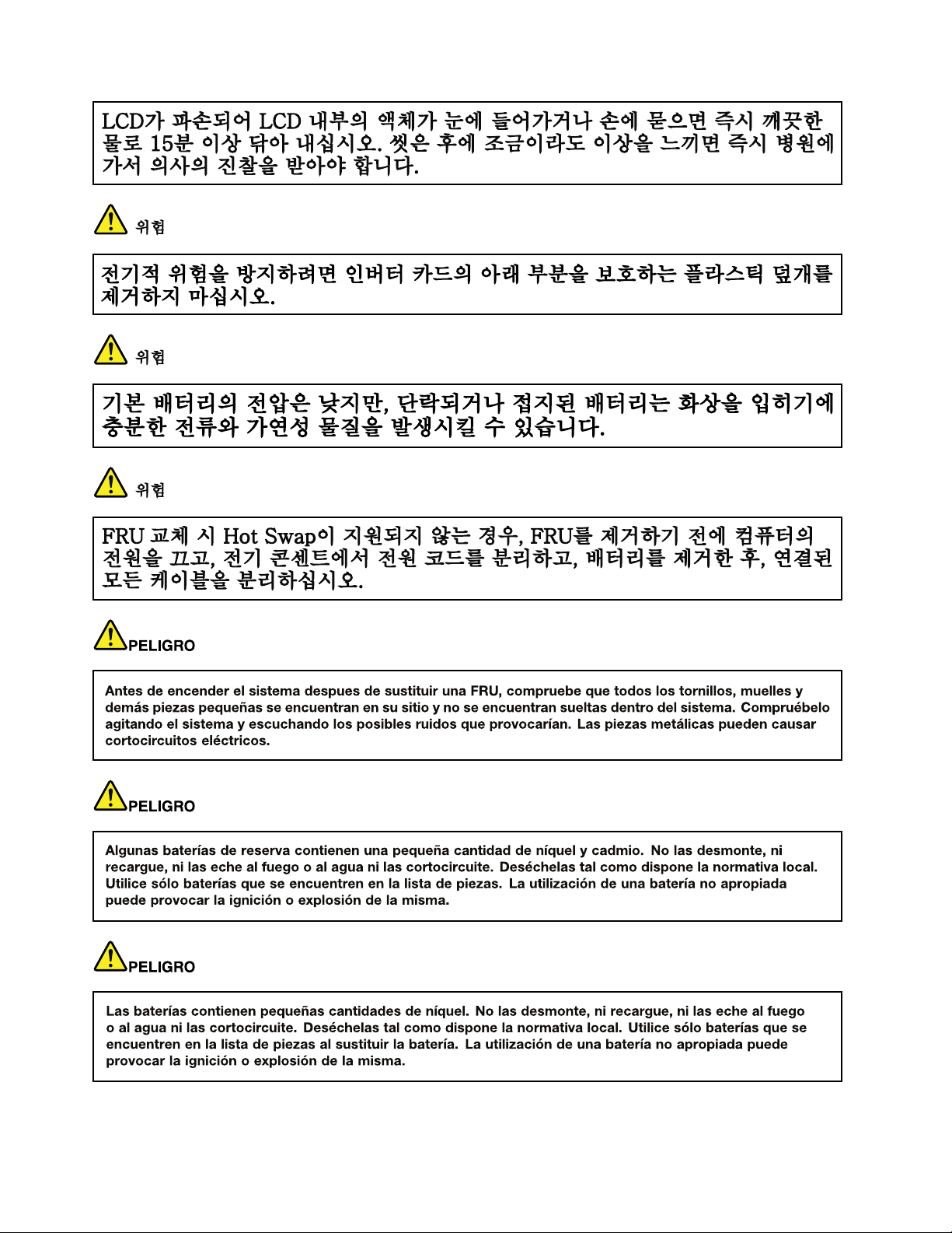
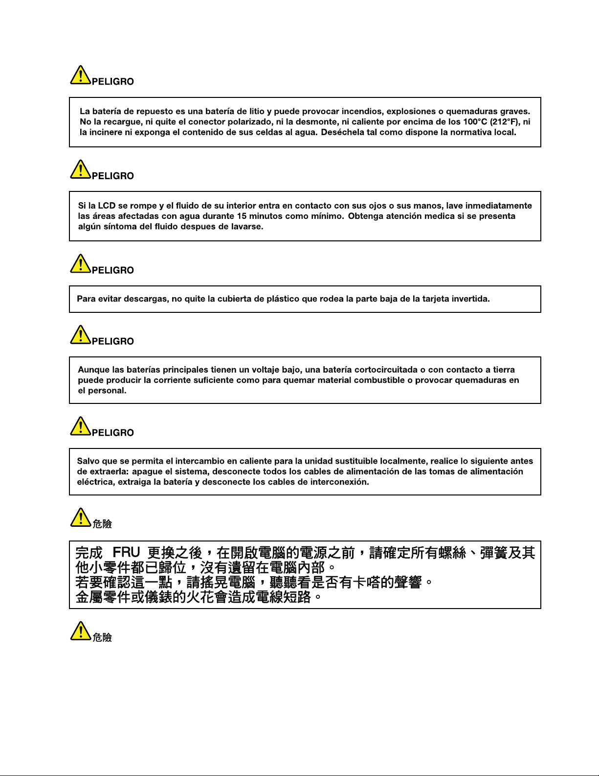
Safetynotices(multilingualtranslations)
Thesafetynoticesinthissectionareprovidedinthefollowinglanguages:
•English
•Arabic
•BrazilianPortuguese
•French
•German
•Hebrew
•Japanese
•Korean
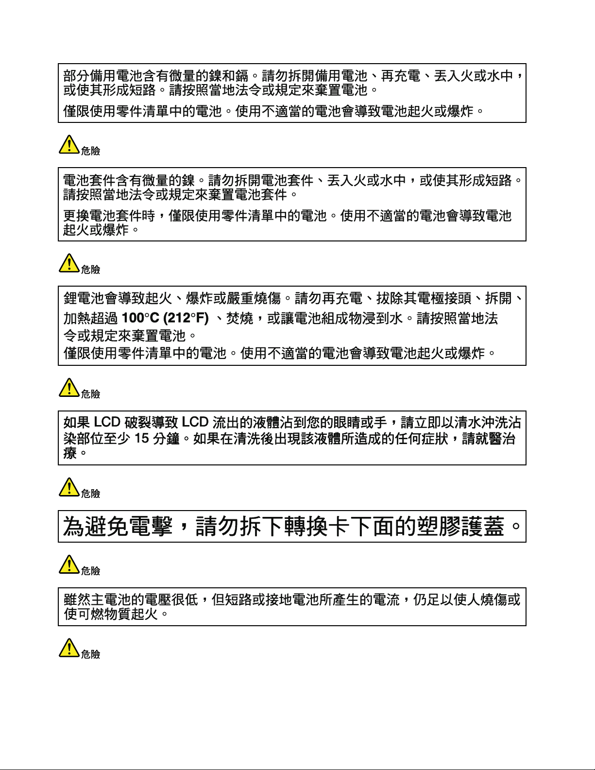
•Spanish
•T raditionalChinese
DANGER
DANGER
4HardwareMaintenanceManual
Page 11
DANGER
DANGER
DANGER
DANGER
DANGER
Chapter1.Safetyinformation5
Page 12
DANGER
6HardwareMaintenanceManual
Page 13
Chapter1.Safetyinformation7
Page 14
PERIGO
PERIGO
PERIGO
PERIGO
PERIGO
PERIGO
8HardwareMaintenanceManual
Page 15
PERIGO
PERIGO
DANGER
DANGER
DANGER
Chapter1.Safetyinformation9
Page 16
DANGER
DANGER
DANGER
DANGER
DANGER
VORSICHT
10HardwareMaintenanceManual
Page 17
VORSICHT
VORSICHT
VORSICHT
VORSICHT
Chapter1.Safetyinformation11
Page 18
VORSICHT
VORSICHT
VORSICHT
12HardwareMaintenanceManual
Page 19
Chapter1.Safetyinformation13
Page 20
14HardwareMaintenanceManual
Page 21
Chapter1.Safetyinformation15
Page 22
16HardwareMaintenanceManual
Page 23
Chapter1.Safetyinformation17
Page 24
18HardwareMaintenanceManual
Page 25
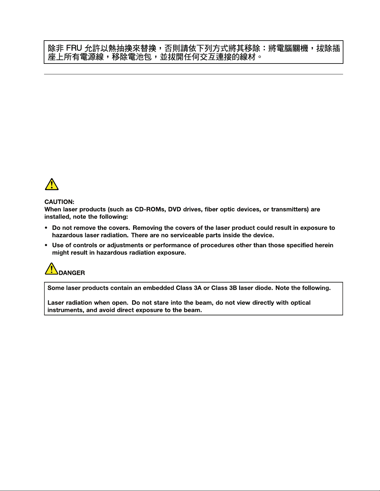
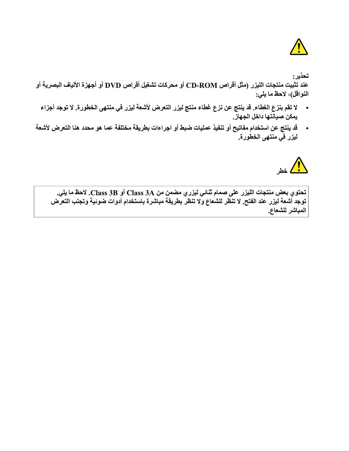
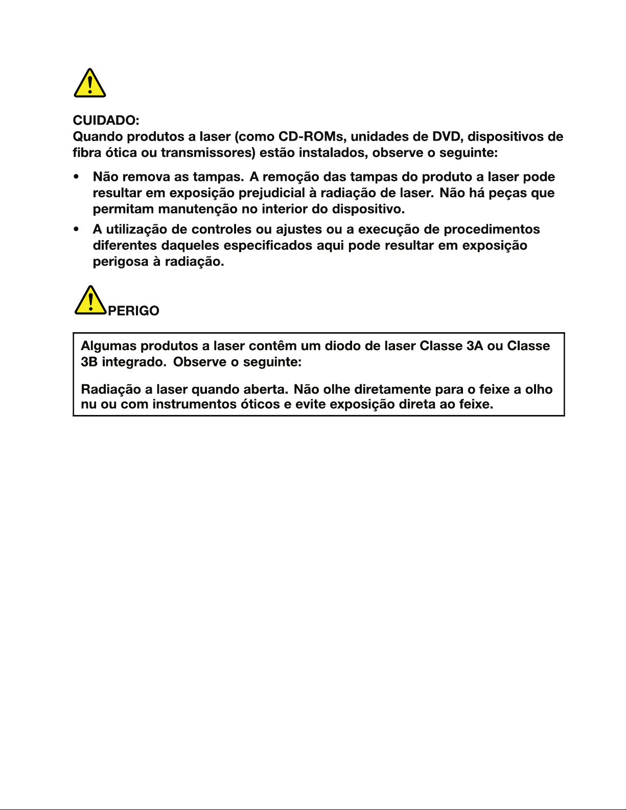
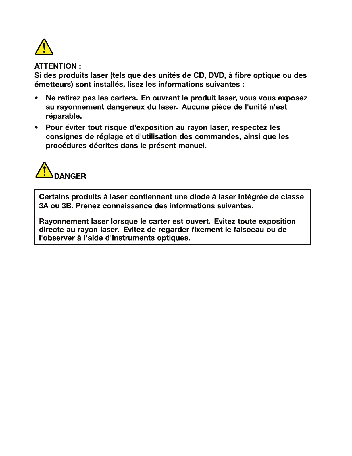
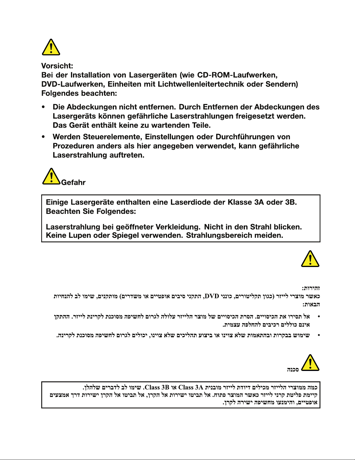
Lasercompliancestatement(multilingualtranslations)
Thelasercompliancestatementsinthissectionareprovidedinthefollowinglanguages:
•English
•Arabic
•BrazilianPortuguese
•French
•German
•Hebrew
•Japanese
•Korean
•Spanish
•T raditionalChinese
Chapter1.Safetyinformation19
Page 26
20HardwareMaintenanceManual
Page 27
Chapter1.Safetyinformation21
Page 28
22HardwareMaintenanceManual
Page 29
Chapter1.Safetyinformation23
Page 30
24HardwareMaintenanceManual
Page 31

Chapter1.Safetyinformation25
Page 32

26HardwareMaintenanceManual
Page 33

Chapter2.Importantserviceinformation
Thischapterpresentsthefollowingimportantserviceinformationthatappliestoallmachinetypessupported
bythismanual:
•“StrategyforreplacingFRUs”onpage27
–“Strategyforreplacingaharddiskdrive”onpage28
–“Importantnoticeforreplacingasystemboard”onpage28
•“ImportantinformationaboutreplacingRoHScompliantFRUs”onpage28
Important:BIOSanddevicedriverxesarecustomer-installable.TheBIOSanddevicedriversareavailable
athttp://www.lenovo.com/support.
StrategyforreplacingFRUs
Beforereplacingparts:
Makesurethatallsoftwarexes,drivers,andBIOSdownloadsareinstalledbeforereplacinganyFRUs
listedinthismanual.
Afterasystemboardisreplaced,ensurethatthelatestBIOSisinstalledtothesystemboardbefore
completingtheserviceaction.
Todownloadsoftwarexes,drivers,andBIOS,dothefollowing:
1.Gotohttp://www.lenovo.com/support.
2.ClickDownloadDrivers&Software.TheWebsiteoffersthreeoptionstobeginyoursearch:
•Searchbyproductnumber
•Searchthroughtheproductauto-detectfunction
•Searchbyproductcategory
3.Followthedirectionsonthescreenandinstallthenecessarysoftware.
4.Restartthecomputer.
Notes:Ifyouneedtoimprovethecomputerperformance,youalsocoulddownloadandinstallthelatest
BIOSutilityfromtheSupportWebsite.
•DonottrytoupdatetheBIOSsettingsforanycomputerunlessyouhavebeentrainedandcertied.An
untrainedpersonrunstheriskofdamagingthecomputer.
•Beforeinstallingthelatestutility,makesurethatthebatteryisfullychargedandanacpoweradapteris
connected.
•Donotturnofforputyourcomputerintosleeporhibernationuntiltheupdatehasbeencompleted.
Otherwise,thesystemboardmightbedamaged.
UsethefollowingstrategytopreventunnecessaryexpenseforreplacingandservicingFRUs:
•IfyouareinstructedtoreplaceaFRUbutthereplacementdoesnotcorrecttheproblem,reinstall
theoriginalFRUbeforeyoucontinue.
•Somecomputershavebothaprocessorboardandasystemboard.Ifyouareinstructedtoreplaceeither
theprocessorboardorthesystemboard,andreplacingoneofthemdoesnotcorrecttheproblem,
reinstallthatboard,andthenreplacetheotherone.
©CopyrightLenovo2012,2013
27
Page 34

•IfanadapteroradeviceconsistsofmorethanoneFRU,anyoftheFRUsmaybethecauseoftheerror.
Beforereplacingtheadapterordevice,removetheFRUs,onebyone,toseeifthesymptomschange.
ReplaceonlytheFRUthatchangedthesymptoms.
Strategyforreplacingaharddiskdrive
Alwaystrytorunalow-levelformatbeforereplacingaharddiskdrive(HDD).Thiswillcauseallcustomerdata
ontheharddisktobelost.Besurethatthecustomerhasacurrentbackupofthedatabeforedoingthistask.
Attention:Thedrivestartupsequenceinthecomputeryouareservicingmayhavebeenchanged.Be
extremelycarefulduringwriteoperationssuchascopying,saving,orformatting.Ifyouselectanincorrect
drive,dataorprogramscanbeoverwritten.
Importantnoticeforreplacingasystemboard
Somecomponentsmountedonasystemboardareverysensitive.Improperhandlingofasystemboardcan
causedamagetothosecomponents,andmaycauseasystemmalfunction.
Attention:Whenhandlingasystemboard:
•Donotdropasystemboardorapplyanyexcessiveforcetoit.
•Avoidroughhandlingofanykind.
•AvoidbendingasystemboardandhardpushingtopreventcrackingateachBGA(BallGridArray)chipset.
ImportantinformationaboutreplacingRoHScompliantFRUs
RoHS,TheRestrictionofHazardousSubstancesinElectricalandElectronicEquipmentDirective
(2002/95/EC)isaEuropeanUnionlegalrequirementaffectingtheglobalelectronicsindustry.RoHS
requirementsmustbeimplementedonLenovoproductsplacedonthemarketafterJune2006.Products
onthemarketbeforeJune2006arenotrequiredtohaveRoHScompliantparts.IftheoriginalFRUparts
arenon-compliant,thereplacementpartsalsocanbenon-compliant.Thatis,iftheoriginalFRUpartsare
RoHScompliant,thereplacementpartalsomustbeRoHScompliant.
Note:RoHSandnon-RoHSFRUpartnumberswiththesametandfunctionareidentiedbytheunique
FRUpartnumbers.
LenovoplanstotransittoRoHScompliancebeforetheimplementationdateandexpectsitssupplierstobe
readytomeetLenovo’srequirementsandscheduleintheEuropeanUnion.Productssoldbetween2005
and2006mightcontainsomeRoHScompliantFRUs.Thefollowingstatementpertainstotheproducts
withRoHScompliantFRUs.
RoHScompliantFRUshaveuniqueFRUpartnumbers.BeforeoraftertheRoHSimplementationdate,the
failedRoHScompliantpartsmustbereplacedwithcompliantpartsandonlythefollowingFRUscanbe
used:identiedascompliantintheHardwareMaintenanceManualordirectsubstitutionscanbeused.
•CompliantFRUsidentiedinHardwareMaintenanceManual
•DirectsubstitutionswithdifferentFRUpartnumbersautomaticallyshippedbythedistributioncenterat
thetimeoforder
ForproductsshippedafterJune2006
Currentororiginalpart
MustbeRoHSMustbeRoHS
28HardwareMaintenanceManual
ReplacementFRU
Page 35

Chapter3.Generalcheckout
Thischapterpresentsfollowinginformation:
•“Whattodorst”onpage29
•“Powersystemcheckout”onpage30
Beforeyougotothecheckoutguide,besuretoreadthefollowingimportantnotes.
Importantnotes:
•Onlycertiedtrainedpersonnelshouldservicethecomputer.
•BeforereplacinganyFRU,readtheentirepageonremovingandreplacingFRUs.
•WhenyoureplaceFRUs,itisrecommendedtousenewnylon-coatedscrews.
•Beextremelycarefulduringsuchwriteoperationsascopying,saving,orformatting.Drivesinthecomputer
thatyouareservicingsequencemighthavebeenaltered.Ifyouselectanincorrectdrive,dataorprograms
mightbeoverwritten.
•ReplaceaFRUonlywithanotherFRUofthecorrectmodel.WhenyoureplaceaFRU,makesurethatthemodel
ofthemachineandtheFRUpartnumberarecorrectbyreferringtotheFRUpartslist.
•AFRUshouldnotbereplacedbecauseofasingle,unreproduciblefailure.Singlefailurescanoccurfora
varietyofreasonsthathavenothingtodowithahardwaredefect,suchascosmicradiation,electrostaticdischarge,
orsoftwareerrors.ConsiderreplacingaFRUonlywhenaproblemrecurs.IfyoususpectthataFRUisdefective,
cleartheerrorlogandrunthetestagain.Iftheerrordoesnotrecur,donotreplacetheFRU.
•BecarefulnottoreplaceanondefectiveFRU.
Whattodorst
WhenyoudoreturnaFRU,youmustincludethefollowinginformationinthepartsexchangeformor
partsreturnformthatyouattachtoit:
1.Nameandphonenumberofservicetechnician
2.Dateofservice
3.Dateonwhichthemachinefailed
4.Dateofpurchase
5.ProcedureindexandpagenumberinwhichthefailingFRUwasdetected
6.FailingFRUnameandpartnumber
7.Machinetype,modelnumber,andserialnumber
8.Customer'snameandaddress
Note:Duringthewarrantyperiod,thecustomermayberesponsibleforrepaircostsifthecomputerdamage
wascausedbymisuse,accident,modication,unsuitablephysicaloroperatingenvironment,orimproper
maintenancebythecustomer.Followingisalistofsomecommonitemsthatarenotcoveredunderwarranty
andsomesymptomsthatmightindicatethatthesystemwassubjectedtostressbeyondnormaluse.
Beforecheckingproblemswiththecomputer,determinewhetherthedamageiscoveredunderthewarranty
byreferringtothefollowinglist:
Thefollowingarenotcoveredunderwarranty:
•LCDpanelcrackedfromtheapplicationofexcessiveforceorfrombeingdropped
•Scratched(cosmetic)parts
•Distortion,deformation,ordiscolorationofthecosmeticparts
•Plasticparts,latches,pins,orconnectorsthathavebeencrackedorbrokenbyexcessiveforce
•Damagecausedbyliquidspilledintothesystem
•DamagecausedbytheimproperinsertionofaPCCardortheinstallationofanincompatiblecard
•Improperdiscinsertionoruseofanopticaldrive
©CopyrightLenovo2012,2013
29
Page 36

•Diskettedrivedamagecausedbypressureonthediskettedrivecover,foreignmaterialinthedrive,
2
1
ortheinsertionofadiskettewithmultiplelabels
•Damagedorbentdisketteejectbutton
•Fusesblownbyattachmentofanonsupporteddevice
•Forgottencomputerpassword(makingthecomputerunusable)
•Stickykeyscausedbyspillingaliquidontothekeyboard
•Useofanincorrectacpoweradapteronlaptopproducts
Thefollowingsymptomsmightindicatedamagecausedbynonwarrantedactivities:
•Missingpartsmightbeasymptomofunauthorizedserviceormodication.
•Ifthespindleofaharddiskdrivebecomesnoisy,itmayhavebeensubjectedtoexcessiveforce,
ordropped.
Powersystemcheckout
Toverifyasymptom,dothefollowing:
1.T urnoffthecomputer.
2.Removethebatterypack.
3.Connecttheacpoweradapter.
4.Checkthatpowerissuppliedwhenyouturnonthecomputer.
5.T urnoffthecomputer.
6.Disconnecttheacpoweradapterandinstallthechargedbatterypack.
7.Checkthatthebatterypacksuppliespowerwhenyouturnonthecomputer.
Ifyoususpectapowerproblem,seetheappropriateoneofthefollowingpowersupplycheckouts:
•“Checkingtheacpoweradapter”onpage30
•“Checkingoperationalcharging”onpage31
•“Checkingthebatterypack”onpage31
Checkingtheacpoweradapter
Youareherebecausethecomputerfailsonlywhentheacpoweradapterisused.
•Ifthepower-onindicatordoesnotturnon,checkthepowercordoftheacpoweradapterforcorrect
continuityandinstallation.
•Ifthecomputerdoesnotchargeduringoperation,goto“Checkingoperationalcharging”onpage31
Tochecktheacpoweradapter,dothefollowing:
1.Unplugtheacpoweradaptercablefromthecomputer.
2.Measuretheoutputvoltageattheplugoftheacpoweradaptercable.Seethefollowinggure:
Pin
1+20
20
Note:Outputvoltageacrosspin2oftheacpoweradaptermaydifferfromtheoneyouareservicing.
3.Ifthevoltageisnotcorrect,replacetheacpoweradapter.
4.Ifthevoltageisacceptable,dothefollowing:
Voltage(Vdc)
•Replacethesystemboard.
30HardwareMaintenanceManual
Page 37

•Iftheproblempersists,gotoChapter5“ZhaoY angK49”onpage37.
1(+)
2(+)
3
4
5
6(-)
7(-)
Note:Noisefromtheacpoweradapterdoesnotalwaysindicateadefect.
Checkingoperationalcharging
Tocheckwhetherthebatterychargesproperlyduringoperation,useadischargedbatterypackorabattery
packthathaslessthan50%ofthetotalpowerremainingwheninstalledinthecomputer.
Performoperationalcharging.Ifthebatterystatusindicatororicondoesnotturnon,removethebattery
packandletitreturntoroomtemperature.Reinstallthebatterypack.Ifthechargeindicatororiconstilldoes
notturnon,replacethebatterypack.
Ifthechargeindicatorstilldoesnotturnon,replacethesystemboard.Thenreinstallthebatterypack.Ifitis
stillnotcharged,gotothenextsection.
Checkingthebatterypack
ThebatterystatusiconintheWindows
TocheckfordetailedbatterystatusinformationontheWindowsoperatingsystem,dothefollowing:
•Windows7:LaunchthePowerManagerprogramandclicktheBatterytab.
•Windows8:
–PresstherecoverybuttontolaunchtheLenovoSolutionCenterprogram,andthenclickBattery.
–LaunchtheLenovoSettingsprogramfromtheStartscreen,andthenclickPower.
®
noticationareadisplaysthepercentageofbatterypowerremaining.
Tocheckthebatterypack,dothefollowing:
1.T urnoffthecomputeranddisconnecttheacpoweradapter.
2.Removethebatterypackandmeasurethevoltagebetweenbatteryterminals1(+)and7(-).
Terminal
1+0to+14
7
3.Ifthevoltageislessthan+11.0Vdc,thebatterypackhasbeendischarged.
Note:Rechargingwilltakeatleast3hours,eveniftheindicatordoesnotturnon.
Ifthevoltageisstilllessthan+11.0Vdcafterrecharging,replacethebatterypack.
4.Ifthevoltageismorethan+11.0Vdc,measuretheresistancebetweenbatteryterminals5and7.
Theresistancemustbe4to30KΩ.
Iftheresistanceisnotcorrect,replacethebatterypack.Iftheresistanceiscorrect,replacethesystem
board.
Voltage(Vdc)
Ground(-)
Chapter3.Generalcheckout31
Page 38

32HardwareMaintenanceManual
Page 39

Chapter4.Relatedserviceinformation
Thischapterpresentsthefollowinginformation:
•“Recoveringthecomputersettings”onpage33
•“Passwords”onpage33
•“Powermanagement”onpage34
Recoveringthecomputersettings
Thistopicprovidesinformationabouttherecoveryprogramsthatareavailableforyoutorecoverthe
computersettings.
•Windows7:ThefollowingrecoveryprogramsareavailableoncomputerswithaWindows7operating
system:
–OneKey
TheOneKeyRecoveryProprogramenablesyoutobackupallyourharddiskdrivecontents,including
theoperatingsystem,datales,softwareprograms,andpersonalsettings.Y oucandesignatewhere
theOneKeyRecoveryProprogramstoresthebackup.Afteryouhavebackedupthecontentsonthe
harddiskdrive,youcanrestorethecompletecontentsoftheharddiskdrive,restoreonlythedesired
les,orrestoreonlytheWindowsoperatingsystemandapplications.
–ProductRecovery
TheProductRecoveryprogramenablesyoutorestorethecomputersettingstothefactorydefault
settingsthroughrecoverymedia.
®
RecoveryPro
Attention:WhenyouusetheProductRecoveryprogramtorestorethecomputersettings,allthedata
youhavestoredontheharddiskdrivewillbedeletedandthecomputersettingswillberestoredtothe
factorydefaultsettings.Duringtherestoringprocess,youwillbegiventheoptiontosaveoneormore
lescurrentlyontheharddiskdrivetoothermediabeforethedataisdeleted.
•Windows8:ThepreinstalledWindowsrecoveryprogramenablesyoutodothefollowing:
–Refreshingthecomputerwithoutlosingpersonalles
–Restoringthecomputertothefactorydefaultsettings
Attention:WhenyouusetheWindowsrecoveryprogramtorestorethecomputersettings,allthedata
youhavestoredontheharddiskdrivewillbedeletedandthecomputerwillberestoredtothefactory
defaultsettings.T oavoiddataloss,backupyourdatainadvance.
–Conguringtheadvancedstartupoptions
Theadvancedstartupoptionsenableyoutodothefollowing:
–ChangingthestartupsettingsoftheWindowsoperatingsystem
–RestoringtheWindowsoperatingsystemfromasystemimage
–Startingupfromanexternaldevice
Formoreinformationabouttherecoverysolutions,refertothehelpinformationsystemoftheprograms.
Passwords
AsmanyastwopasswordsmightbeneededforaLenovonotebookcomputer:thepower-onpassword
andthesupervisorpassword.
©CopyrightLenovo2012,2013
33
Page 40

Ifanyofthesepasswordshasbeenset,apromptforitwillbedisplayedonthescreenwheneverthe
computeristurnedon.Thecomputerdoesnotstartuntilthepasswordisentered.
Note:Ifonlyasupervisorpasswordisset,thepasswordpromptwillnotbedisplayedwhentheoperating
systemisstarted.
Power-onpassword
Apower-onpassword(POP)protectsthesystemfrombeingpoweredonbyanunauthorizedperson.The
passwordmustbeenteredbeforeanoperatingsystemcanbebooted.
Supervisorpassword
Asupervisorpassword(SVP)protectsthesysteminformationstoredintheBIOS.Theusermustenterthe
SVPinordertogetaccesstotheBIOSandchangethesystemconguration.
Attention:IftheSVPhasbeenforgottenandcannotbemadeavailabletotheservicetechnician,thereisno
serviceproceduretoresetthepassword.Thesystemboardmustbereplacedforascheduledfee.
Powermanagement
Note:PowermanagementmodesarenotsupportedforAPMoperatingsystem.
Toreducepowerconsumption,thecomputerhasthreepowermanagementmodes:screenblank,sleep,
andhibernation.
Screenblankmode
Inthefollowingcircumstances,thecomputergoesintoscreenblankmode:
•Thetimesetonthe“Turnoffmonitor”timerontheWindows7operatingsystemexpires.
Toendscreenblankmodeandresumenormaloperation,pressanykey.
•Y ouhavepressedFn+F2.
Toendscreenblankmodeandresumenormaloperation,pressFn+F2.
Sleepmode
Whenthecomputerenterssleepmode,thefollowingeventsoccurinadditiontowhatoccursinscreen
blankmode:
•TheLCDispoweredoff.
•Theharddiskdriveispoweredoff.
•TheCPUstops.
Toentersleepmode,pressFn+F1.
Incertaincircumstances,thecomputergoesintosleepmodeautomatically:
•Ifa“suspendtime”hasbeensetonthetimer,andtheuserdoesnotdoanyoperationwiththekeyboard,
theharddiskdrive,theparallelconnector,orthediskettedrivewithinthattime.
•Ifthebatteryindicatorblinksorange,indicatingthatthebatterypowerislow.
Tocausethecomputertoreturnfromsleepmodeandresumetheoperation,dooneofthefollowing:
•PresstheFnkey.
•OpentheLCDcover.
•T urnonthepowerbutton.
34HardwareMaintenanceManual
Page 41

Also,whenthetimesetontheresumetimerelapses,thecomputerautomaticallyreturnsfromsleepmode
andresumesoperation.
Note:Thecomputerdoesnotacceptanyinputimmediatelyafteritenterssleepmode.Waitafewseconds
beforetakinganyactiontoreenteroperationmode.
Hibernationmode
Inhibernationmode,thefollowingoccurs:
•Thesystemstatus,RAM,VRAM,andsetupdataarestoredontheharddiskdrive.
•Thesystemispoweredoff.
Ifyouhavedenedoneofthefollowingactionsastheeventthatcausesthesystemtogointohibernation
mode,performthataction.
•Closingthelid.
•Pressingthepowerbutton.
Also,thecomputergoesintohibernationmodeautomaticallyineitherofthefollowingconditions:
•Ifa“hibernationtime”hasbeensetonthetimer,andiftheuserdoesnotdoanyoperationwiththe
keyboard,theharddiskdrive,theparallelconnector,orthediskettedrivewithinthattime.
•Ifthetimerconditionsaresatisedinsuspendmode.
Whenthepoweristurnedon,thecomputerreturnsfromhibernationmodeandresumesoperation.The
hibernationleinthebootrecordontheharddiskdriveisread,andsystemstatusisrestoredfromthe
harddiskdrive.
Chapter4.Relatedserviceinformation35
Page 42

36HardwareMaintenanceManual
Page 43

Chapter5.ZhaoY angK49
Thischapterpresentsthefollowingproduct-specicservicereferencesandpartsinformation:
•“Specications”onpage37
•“Statusindicators”onpage38
•“Fnkeycombinations”onpage39
Specications
ThistopicliststhephysicalfeaturesfortheZhaoYangK49models.
Processor
•T oviewtheprocessorinformationofyourcomputer,doeitherofthefollowing:
–Windows7:ClickStart,right-clickComputer.ThenclickProperties.
–Windows8:Fromthedesktop,movethecursortothetop-rightorbottom-rightcornerofthescreento
displaythecharms.ThenclickSettings➙PCinfo.
Memory
•Doubledatarate3(DDR3)synchronousdynamicrandomaccessmemory(SDRAM)
Storagedevice
•2.5-inch(7mmheightor9.5mmheight)harddiskdrive
•mSA T Asolid-statedrive
Note:IfthecomputerisequippedwithbothaharddiskdriveandanmSATAsolid-statedrive,donot
usethemSATAsolid-statedriveasabootabledevice.ThemSATAsolid-statedriveisusedfor“cache”
functiononly.
Display
•Size:14.0inches(356mm)
•Resolution:
–LCD:1366-by-768
–Externalmonitor:Maximum2048-by-1536
•Integratedcamera(onsomemodels)
Keyboard
•6-rowLenovokeyboard
•Fnkeyfunction
•Recoverybutton
•Speakermutebutton
•ActiveProtectionSystem™(APS)button
Interface
•Comboaudiojack(stereoheadphoneorheadset)
©CopyrightLenovo2012,2013
37
Page 44

•T woUSB2.0connectors
1 2
3 4
•T woUSB3.0connectors
•RJ45Ethernetconnector
•HDMIport
•Externalmonitorconnector
•4-in-1digitalmediacardreaderslot
Opticaldrive
•12.7mmRamboopticaldrive(onsomemodels)
Wirelessfeatures
•IntegratedwirelessLAN
•10/100/1000MbpsEthernetcommunication
Securityfeature
•Fingerprintreader(onsomemodels)
Statusindicators
Thischapterpresentsthesystemstatusindicatorsthatshowthestatusofthecomputer.
38HardwareMaintenanceManual
Page 45

Table1.Statusindicators
IndicatorMeaning
1
Batterystatus
indicator
2
Deviceaccess
statusindicator
3
Wirelessstatus
indicator
•Green:Thebatterychargelevelisbetween80%and100%,orthebatterydischarge
levelisbetween20%and100%.
•Slowblinkinggreen:Thebatterychargelevelisbetween20%and80%,and
chargingiscontinuing.Whenthebatterychargelevelreaches80%,thebatterystatus
indicatorstopsblinking,butthechargingmightcontinueuntilthebatteryis100%
charged.
•Slowblinkingorange:Thebatterychargelevelisbetween5%and20%,andthe
chargingiscontinuing.Whenthebatterychargelevelreaches20%,theblinking
colorchangestogreen.
•Orange:Thebatterydischargelevelisbetween5%and20%.
•Fastblinkingorange:Thebatterychargeordischargelevelis5%orless.
•Off:Thebatteryisdetachedorthecomputerispoweredoff.
Whenthisindicatorison,theharddiskdriveortheopticaldriveisreadingorwritingdata.
Attention:
•Whentheindicatorison,donotputthecomputerintosleepmodeorturnoffthe
computer.
•Whentheindicatorison,donotmovethecomputer.Suddenphysicalshockmight
causedriveerrors.
•Blue:Thewirelessnetworkfeatureison.
•Off:Wirelessnetworkdevicesaredisabledorthewirelessradioisturnedoff.
4
APSstatusindicator•On:TheActiveProtectionSystemprogramisactive.
•Off:TheActiveProtectionSystemprogramisinactive.
Fnkeycombinations
ThefollowingtableshowsthefunctionofeachcombinationofFnwithafunctionkey.
Table2.Functionkeycombinations
KeycombinationDescription
Fn+Esc
Fn+F1Enterssleepmode.
Fn+F2
Fn+F3
Fn+F4Enablesordisablesthecamera.
Fn+F5
Fn+F8Enablesordisablesthetouchpad
Fn+F9
Fn+F10
Fn+F11
Turnsonorturnsoffthekeyboardlight.
Enablesordisablesthebacklightfeatureofthecomputerscreen.
Switchesbetweenthecomputerdisplayandanexternalmonitor.
Enablesordisablesthebuilt-inwirelessfeatures.
StartsorpausesplaybackofWindowsMediaPlayer .
StopsplaybackofWindowsMediaPlayer.
Skipstotheprevioustrack.
Fn+F12
Skipstothenexttrack.
Chapter5.ZhaoYangK4939
Page 46

Table2.Functionkeycombinations(continued)
KeycombinationDescription
Fn+InsertEnablesordisablesthenumerickeypad.
Fn+Delete
Fn+PrtSc
Fn+Pause
Fn+up/downarrow
Fn+left/rightarrow
Enablesordisablesthescrolllockfunction.
Activatesthesystemrequest.
Activatesthebreakfunction.
Increasesordecreasesthedisplaybrightnesslevel.
Decreasesorincreasesthesoundvolume.
40HardwareMaintenanceManual
Page 47

Chapter6.FRUreplacementnotices
Thischapterpresentsnoticesrelatedtoremovingandreplacingparts.Readthischaptercarefullybefore
replacinganyFRU.
CRUstatementforcustomers:
Youcanresolvesomeproblemswithyourproductwithareplacementpartyoucaninstallyourself,called
a“CustomerReplaceableUnit”or“CRU.”SomeCRUsaredesignatedasself-serviceCRUsandothers
aredesignatedasoptional-serviceCRUs.Installationofself-serviceCRUsisyourresponsibility.For
optional-serviceCRUs,youcaneitherinstalltheCRUyourselforyoucanrequestthataServiceProvider
installtheCRUaccordingtothewarrantyserviceforyourproduct.IfyouintendoninstallingtheCRU,
LenovowillshiptheCRUtoyou.CRUinformationandreplacementinstructionsareshippedwithyour
productandareavailablefromLenovoatanytimeuponrequest.YoucanndalistofCRUsforyour
productinthisHardwareMaintenanceManual.Anelectronicversionofthismanualcanbefoundat
http://www.lenovo.com/UserManuals.Followtheon-screeninstructionstondthemanualforyourproduct.
YoumightberequiredtoreturnthedefectiveCRU.Whenreturnisrequired:(1)returninstructions,aprepaid
shippinglabel,andacontainerwillbeincludedwiththereplacementCRU;and(2)youmightbechargedfor
thereplacementCRUifLenovodoesnotreceivethedefectiveCRUwithinthirty(30)daysofyourreceiptof
thereplacementCRU.SeeyourLenovoLimitedWarrantydocumentationforfulldetails.
Screwnotices
Loosescrewscancauseareliabilityproblem.IntheLenovonotebookcomputer,thisproblemisaddressed
withspecialnylon-coatedscrewsthathavethefollowingcharacteristics:
•Theymaintaintightconnections.
•Theydonoteasilycomeloose,evenwithshockorvibration.
•Theyarehardertotighten.
Dothefollowingwhenyouservicethismachine:
•Keepthescrewkitinyourtoolbag.
•Itisrecommendedtousenewscrews.
•Itrecommendedtouseeachscrewonlyonce.
•Useatorquescrewdriverifyouhaveone.
Tightenscrewsasfollows:
•Plastictoplastic
Turnanadditional90degreesafterthescrewheadtouchesthesurfaceoftheplasticpart:
•Logiccardtoplastic
Turnanadditional180degreesafterthescrewheadtouchesthesurfaceofthelogiccard:
©CopyrightLenovo2012,2013
41
Page 48

•T orquedriver
Ifyouhaveatorquescrewdriver,refertotheTorquecolumninthescrewinformationtableforeachstep.
•Makesurethatyouusethecorrectscrew.Itisrecommendedtousenewscrewsforreplacements.If
youhaveatorquescrewdriver,tightenallscrewsrmlytothetorquespeciedinthescrewinformation
tableforeachstep.
•Ensuretorquescrewdriversarecalibratedcorrectlyfollowingcountryspecications.
42HardwareMaintenanceManual
Page 49

Chapter7.RemovingandreplacingaFRU
ThischapterprovidesinstructionsonhowtoremoveorreplaceaFRU.
CRUstatementforcustomers:
Youcanresolvesomeproblemswithyourproductwithareplacementpartyoucaninstallyourself,called
a“CustomerReplaceableUnit”or“CRU.”SomeCRUsaredesignatedasself-serviceCRUsandothers
aredesignatedasoptional-serviceCRUs.Installationofself-serviceCRUsisyourresponsibility.For
optional-serviceCRUs,youcaneitherinstalltheCRUyourselforyoucanrequestthataServiceProvider
installtheCRUaccordingtothewarrantyserviceforyourproduct.IfyouintendoninstallingtheCRU,
LenovowillshiptheCRUtoyou.CRUinformationandreplacementinstructionsareshippedwithyour
productandareavailablefromLenovoatanytimeuponrequest.YoucanndalistofCRUsforyour
productinthisHardwareMaintenanceManual.Anelectronicversionofthismanualcanbefoundat
http://www.lenovo.com/UserManuals.Followtheon-screeninstructionstondthemanualforyourproduct.
YoumightberequiredtoreturnthedefectiveCRU.Whenreturnisrequired:(1)returninstructions,aprepaid
shippinglabel,andacontainerwillbeincludedwiththereplacementCRU;and(2)youmightbechargedfor
thereplacementCRUifLenovodoesnotreceivethedefectiveCRUwithinthirty(30)daysofyourreceiptof
thereplacementCRU.SeeyourLenovoLimitedWarrantydocumentationforfulldetails.
Generalguidelines
ThischapterpresentsdirectionsanddrawingsforuseinremovingandreplacingaFRU.Besuretoobserve
thefollowinggeneralrules:
1.Donottrytoserviceanycomputerunlessyouhavebeentrainedandcertied.Anuntrainedpersonruns
theriskofdamagingparts.
2.BeforereplacinganyFRU,reviewChapter6“FRUreplacementnotices”onpage41.
3.BeginbyremovinganyFRUsthathavetoberemovedbeforereplacingthefailingFRU.SuchFRUsare
listedineachFRUreplacementsection.Removethemintheorderinwhichtheyarelisted.
4.FollowthecorrectsequenceinthestepsforremovingaFRU,asgiveninthedrawingsbythenumbers
insquarecallouts.
5.Whenturningascrew,turnitinthedirectionasgivenbythearrowinthedrawing.
6.WhenremovingaFRU,moveitinthedirectionasgivenbythearrowinthedrawing.
7.T oputthenewFRUinplace,reversetheremovalprocedureandfollowanynotesthatpertainto
replacement.
8.WhenreplacingaFRU,usethecorrectscrew(s)asshownintheprocedures.
DANGER
BeforeremovinganyFRU,turnoffthecomputer,unplugallpowercordsfromelectricaloutlets,
removethebatterypack,andthendisconnectanyinterconnectingcables.
Attention:AfterreplacingaFRU,donotturnonthecomputeruntilyouhavemadesurethatallscrews,
springs,andothersmallpartsareinplaceandnonearelooseinsidethecomputer.Verifythisbyshaking
thecomputergentlyandlisteningforrattlingsounds.Metallicpartsormetalakescancauseelectrical
shortcircuits.
Attention:Thesystemboardissensitiveto,andcanbedamagedby,electrostaticdischarge.Before
touchingit,establishpersonalgroundingbytouchingagroundpointwithonehandorbyusingan
electrostaticdischarge(ESD)strap(P/N6405959).
©CopyrightLenovo2012,2013
43
Page 50

1010Batterypack
2
1
2
Removalstepsofbatterypack
DANGER
Useonlytheauthorizedbatteryspeciedforyourcomputer.Anyotherbatterycouldigniteor
explode.
Unlockthebatterylatch1.Holdingtheotherbatterylatch(manual)intheunlockedposition2,remove
thebatterypack.
Wheninstalling:Installthebatterypackintheslot.Makesurethatthebatterylatchesareinthelocked
position.
1020Bottomslotcover
Foraccess,removethisFRU:
•“1010Batterypack”onpage44
44HardwareMaintenanceManual
Page 51

Removalstepsofbottomslotcover
2
1
3
1
2
Loosenthescrews1anddonotremovethem.Thenremovethecover2.
1030Opticaldriveorblankbezel
Foraccess,removetheseFRUsinorder:
•“1010Batterypack”onpage44
•“1020Bottomslotcover”onpage44
Removalstepsofopticaldriveorblankbezel
Removethescrew1.Theninsertascrewdriverintothescrewhole2andpushtheopticaldriveinthe
directionshownbythearrow3.
StepScrew(quantity)Color
1
M2×3mm,at-head,nylon-coated(1)
Torque
Black
1.85kgf-cm
Chapter7.RemovingandreplacingaFRU45
Page 52

Removalstepsofopticaldrivebezelandopticaldrivebracket
1
1
2
Removethescrews1andthenremovetheopticaldrivebracket.
StepScrew(quantity)Color
1
M2×3mm,at-head,nylon-coated(2)
1040Memorymodules
Foraccess,removetheseFRUsinorder:
•“1010Batterypack”onpage44
•“1020Bottomslotcover”onpage44
Torque
Black
1.85kgf-cm
46HardwareMaintenanceManual
Page 53

Removalstepsofmemorymodules
2
1 1
a
b
Releasethetwolatchesonbothedgesofthesocketatthesametimeinthedirectionshownbythearrows
1,andthenunplugthememorymoduleinthedirectionshownbythearrow2.
Wheninstalling:Insertthenotchedendofthememorymoduleintotheslot.Pressthememorymodule
rmly,andpivotituntilitsnapsintoplace.Makesurethatitisrmlyinstalledintheslotanddoesnot
moveeasily.
Note:Ifonlyonememorymoduleistobeinstalledonthecomputeryouareservicing,thememorymodule
mustbeinstalledinSLOT -0(
alowerslot),butnotinSLOT -1(bupperslot).
1050Harddiskdriveassembly
Foraccess,removetheseFRUsinorder:
•“1010Batterypack”onpage44
•“1020Bottomslotcover”onpage44
Attention:
•Donotdropthedriveorapplyanyphysicalshocktoit.Thedriveissensitivetophysicalshock.Improper
handlingcancausedamageandpermanentlossofdata.
•Beforeremovingthedrive,havetheusermakeabackupcopyofalltheinformationonitifpossible.
•Neverremovethedrivewhilethecomputerisoperatingorisinsuspendmode.
Chapter7.RemovingandreplacingaFRU47
Page 54

Removalstepsofharddiskdriveassembly
1
1
2
3
Removethescrews1.Thenpullthetabinthedirectionshownbythearrow2.
StepScrew(quantity)Color
1
M2×3mm,at-head,nylon-coated(1)
Black
Torque
1.85kgf-cm
Removetheharddiskdrivefromtheslot3.
Wheninstalling:Makesurethattheharddiskdriveconnectorisattachedrmly.
48HardwareMaintenanceManual
Page 55

Removalstepsofharddiskdrivebracket
1
1
1
1
2
Removethescrews1.
StepScrew(quantity)Color
1
M3×2.8mm,at-head,nylon-coated(4)
Removetheharddiskdrivebracketinthedirectionshownbythearrow2.
1060PCIExpressMiniCardforwirelessLAN
Foraccess,removetheseFRUsinorder:
•“1010Batterypack”onpage44
•“1020Bottomslotcover”onpage44
Torque
Black
4.0kgf-cm
Chapter7.RemovingandreplacingaFRU49
Page 56

RemovalstepsofPCIExpressMiniCardforwirelessLAN
2
1
1
3
Insteps1,unplugtheconnectorsusingtheremovaltoolantennaRFconnector(P/N:08K7159)orpickthe
connectorswithyourngersandgentlyunplugtheminthedirectionofthearrows.Thenremovethescrew2.
StepScrew(quantity)Color
2
M2×3mm,at-head,nylon-coated(1)
Black
Torque
1.85kgf-cm
Removethecardinthedirectionshownbythearrow3.
Wheninstalling:Plugtheblackcable(MAIN)intothejacklabeledM,andthewhitecable(AUX)intothejack
labeledAonthecard.
50HardwareMaintenanceManual
Page 57

1070mSA TAsolid-statedrive(onsomemodels)
1
Foraccess,removetheseFRUsinorder:
•“1010Batterypack”onpage44
•“1020Bottomslotcover”onpage44
Attention:
•Donotdropthedriveorapplyanyphysicalshocktoit.Thedriveissensitivetophysicalshock.Improper
handlingcancausedamageandpermanentlossofdata.
•Beforeremovingthedrive,havetheusermakeabackupcopyofalltheinformationonitifpossible.
•Neverremovethedrivewhilethecomputerisoperatingorisinsuspendmode.
RemovalstepsofmSATAsolid-statedrive
Removethescrew1.
StepScrew(quantity)Color
1
M2×3mm,at-head,nylon-coated(1)
Torque
Black
Chapter7.RemovingandreplacingaFRU51
1.85kgf-cm
Page 58

RemovethemSATAsolid-statedriveinthedirectionshownbythearrow2.
2
1
1080Thermalmodule
Foraccess,removetheseFRUsinorder:
•“1010Batterypack”onpage44
•“1020Bottomslotcover”onpage44
Removalstepsofthermalmodule
Detachthefanconnector1.
Wheninstalling:Makesurethattheconnectorisattachedrmly.
52HardwareMaintenanceManual
Page 59

Loosenthescrews2to8,anddonotremovethem.
5
2
4
3
7
8
6
Chapter7.RemovingandreplacingaFRU53
Page 60

Liftthefanassemblyinthedirectionshownbythearrow9.
9
a
b
Note:Becarefulnottodamagetheconnector.
Wheninstalling:Beforeyouattachthethermalmoduletothecomputer,applythermalgrease,atanamount
of0.2grams,onthepartmarkedaandbasshowninthefollowingillustration.Eithertoomuchortooless
applicationofgreasecancauseathermalproblemduetoimperfectcontactwithacomponent.
1090CPU
Foraccess,removetheseFRUsinorder:
•“1010Batterypack”onpage44
•“1020Bottomslotcover”onpage44
•“1080Thermalmodule”onpage52
Attention:TheCPUisextremelysensitive.WhenyouservicetheCPU,avoidanykindofroughhandling.
54HardwareMaintenanceManual
Page 61

RemovalstepsofCPU
22
a
b
1
Rotatetheheadofthescrewinthedirectionshownbythearrow1toreleasethelock;thenremovethe
CPU2.
Wheninstalling:PlacetheCPUabovetheCPUsocketa,andthenrotatetheheadofthescrewinthe
directionshownbythearrowbtosecuretheCPU.
1100Keyboard
Foraccess,removetheseFRUsinorder:
•“1010Batterypack”onpage44
•“1020Bottomslotcover”onpage44
Chapter7.RemovingandreplacingaFRU55
Page 62

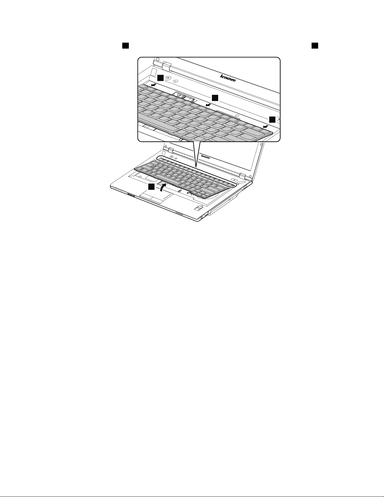
Removalstepsofkeyboard
1
1
2
2
Removethescrews1.
Wheninstalling:Makesurethatthescrewsarefastenedandthekeyboardissecured.
StepScrew(quantity)Color
1
M2×6mm,at-head,nylon-coated(2)
Black
Pushhardinthedirectionshownbythearrows2tounlatchthefrontsideofthekeyboard.
Torque
1.85kgf-cm
56HardwareMaintenanceManual
Page 63
Detachthekeyboardlightly3.Thenremovethekeyboardinthedirectionshownbythearrows4.
3
4
4
4
Chapter7.RemovingandreplacingaFRU57
Page 64

Carefullyliftthekeyboarduntilyoucanseehowit’sconnected.Holdthekeyboardabovethecomputer,and
5
6
7
thendetachthekeyboardconnector7.
Wheninstalling:Makesurethatthekeyboardconnectorisattachedrmly.
1110Keyboardbezel
Foraccess,removetheseFRUsinorder:
•“1010Batterypack”onpage44
•“1020Bottomslotcover”onpage44
•“1030Opticaldriveorblankbezel”onpage45
•“1100Keyboard”onpage55
58HardwareMaintenanceManual
Page 65

Removalstepsofkeyboardbezel
1
1
1
1
1
1
2
2
2
1
3
3
3
1
1
1
4
4
Removethescrews1,2,and3thatsecurethekeyboardbezel.
StepScrew(quantity)Color
1
2
3
M2×6mm,at-head,nylon-coated(10)
M2×3mm,at-head,nylon-coated(3)
M2×3mm,at-head,nylon-coated(3)
Black
Black
Black
Torque
1.85kgf-cm
1.85kgf-cm
1.85kgf-cm
Removethescrews4.
StepScrew(quantity)Color
4
M2×6mm,at-head,nylon-coated(2)
Torque
Black
Chapter7.RemovingandreplacingaFRU59
1.85kgf-cm
Page 66

Detachtheconnectorsinthefollowingillustration.
12
11
13
8
7
6
5
9
10
14
14
14
14
14
14
14
14
14
15
Wheninstalling:Makesurethatalltheconnectorsareattachedrmly.
Insteps
14,releasethekeyboardbezelfromtheframeusingaplasticprytoolasshowninthefollowing
illustration.
1120Fingerprintboard
Foraccess,removetheseFRUsinorder:
•“1010Batterypack”onpage44
•“1020Bottomslotcover”onpage44
60HardwareMaintenanceManual
Page 67

•“1030Opticaldriveorblankbezel”onpage45
1
2
3
3
3
•“1100Keyboard”onpage55
•“1110Keyboardbezel”onpage58
Removalstepsofngerprintboard
Removethescrew1.Thenremovethengerprintboardbracket2andngerprintboard3.
StepScrew(quantity)Color
1
M2×3mm,at-head,nylon-coated(1)
Black
Torque
1.85kgf-cm
1130Functionboardandmicrophone
Foraccess,removetheseFRUsinorder:
•“1010Batterypack”onpage44
•“1020Bottomslotcover”onpage44
•“1030Opticaldriveorblankbezel”onpage45
•“1100Keyboard”onpage55
•“1110Keyboardbezel”onpage58
Chapter7.RemovingandreplacingaFRU61
Page 68

Removalstepsoffunctionboard
2
2
1
1
1
1
1
1
1
Removethescrew1.Thenremovethefunctionboardinthedirectionshownbythearrow2.
StepScrew(quantity)Color
1
M2×3mm,at-head,nylon-coated(1)
Removalstepsofmicrophone
Peeloffthemylartapes1.
Torque
Black
1.85kgf-cm
62HardwareMaintenanceManual
Page 69

Removethemicrophoneinthedirectionshownbythearrow2.
2
2
2
1
2
2
1140Powerboard
Foraccess,removetheseFRUsinorder:
•“1010Batterypack”onpage44
•“1020Bottomslotcover”onpage44
•“1030Opticaldriveorblankbezel”onpage45
•“1100Keyboard”onpage55
•“1110Keyboardbezel”onpage58
Removalstepsofpowerboard
Removethescrew1.Thenremovethepowerboardinthedirectionshownbythearrows2..
StepScrew(quantity)Color
1
M2×3mm,at-head,nylon-coated(1)
Black
Torque
1.85kgf-cm
1150Backupbattery
Foraccess,removetheseFRUsinorder:
•“1010Batterypack”onpage44
•“1020Bottomslotcover”onpage44
•“1030Opticaldriveorblankbezel”onpage45
•“1100Keyboard”onpage55
•“1110Keyboardbezel”onpage58
Chapter7.RemovingandreplacingaFRU63
Page 70

Removalstepsofbackupbattery
DANGER
Useonlytheauthorizedbatteryspeciedforyourcomputer.Anyotherbatterycouldigniteor
explode.
Insertascrewdriverintothescrewholeandpushthebackupbatteryasshowninthefollowingillustration.
1160Speakerassembly
Foraccess,removetheseFRUsinorder:
•“1010Batterypack”onpage44
•“1020Bottomslotcover”onpage44
•“1030Opticaldriveorblankbezel”onpage45
•“1100Keyboard”onpage55
•“1110Keyboardbezel”onpage58
64HardwareMaintenanceManual
Page 71

Removalstepsofspeakerassembly
3
4
1
2
5
5
5
5
6
6
DetachLCDcable2.Thendisconnectthespeakerassemblyconnectors3and4.
Removethescrews5.Thenremovethespeakerassemblyinthedirectionshownbythearrows6.
StepScrew(quantity)Color
5
M2.5×5.7mm,at-head,nylon-coated(4)
Torque
Black
Chapter7.RemovingandreplacingaFRU65
1.85kgf-cm
Page 72

1170Systemboardassembly
4
5
2
3
1
1
1
Importantnoticesforhandlingthesystemboard:
Whenhandlingthesystemboard,bearthefollowinginmind:
•Becarefulnottodropthesystemboardonabenchtopthathasahardsurface,suchasmetal,wood,orcomposite.
•Avoidroughhandlingofanykind.
•Ateverypointintheprocess,besurenottodroporstackthesystemboard.
•Ifyouputasystemboarddown,besuretoputitonlyonapaddedsurfacesuchasanESDmatoracorrugated
conductivesurface.
Foraccess,removetheseFRUsinorder:
•“1010Batterypack”onpage44
•“1020Bottomslotcover”onpage44
•“1030Opticaldriveorblankbezel”onpage45
•“1040Memorymodules”onpage46
•“1050Harddiskdriveassembly”onpage47
•“1060PCIExpressMiniCardforwirelessLAN”onpage49
•“1070mSATAsolid-statedrive(onsomemodels)”onpage51
•“1100Keyboard”onpage55
•“1110Keyboardbezel”onpage58
•“1150Backupbattery”onpage63
•“1160Speakerassembly”onpage64
Removalstepsofsystemboardassembly
Removethescrews1.ThendetachLCDcable3andspeakerassemblyconnectors4and5.
StepScrew(quantity)Color
1
M2×3mm,at-head,nylon-coated(3)
Black
Torque
1.85kgf-cm
66HardwareMaintenanceManual
Page 73
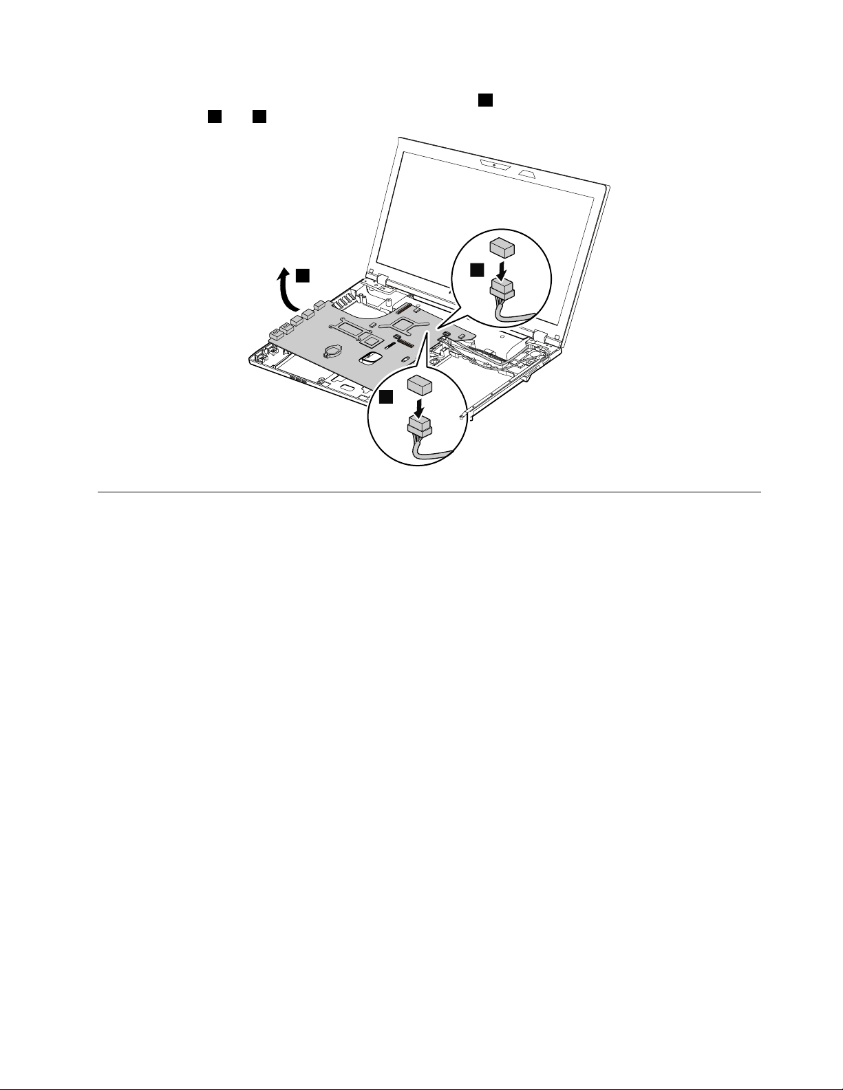
Removethesystemboardinthedirectionshownbythearrow6.ThendetachtheandDC-incableandUSB
7
8
6
cableconnectors7and8.
1180LCDunit
Foraccess,removetheseFRUsinorder:
•“1010Batterypack”onpage44
•“1020Bottomslotcover”onpage44
•“1030Opticaldriveorblankbezel”onpage45
•“1060PCIExpressMiniCardforwirelessLAN”onpage49
•“1100Keyboard”onpage55
•“1110Keyboardbezel”onpage58
•“1170Systemboardassembly”onpage66
Chapter7.RemovingandreplacingaFRU67
Page 74

RemovalstepsofLCDunit
1
1
1
1
Releasetheantennacablesfromthecableguides.Thenremovethescrews1.
StepScrew(quantity)Color
1
M2.5×6mm,at-head,nylon-coated(4)
Black
Torque
1.6kgf-cm
Wheninstalling:
•Routetheantennacablesalongthecableguides.Asyouroutethecables,makesurethattheyarenot
subjecttoanytension.Tensioncouldcausethecablestobedamagedbythecableguides,orawireto
bebroken.
•MakesurethattheLCDconnectorisattachedrmlyandmakesurethatyoudonotpinchtheantenna
cableswhenyouattachtheLCDassembly.RoutetheLCDcablealongthecableguides.
68HardwareMaintenanceManual
Page 75

RemovetheLCDunitinthedirectionshownbythearrows2.
2
2
1190DC-inbracket,DC-incable,USBbracket,USBcable,andbase cover
Foraccess,removetheseFRUsinorder:
•“1010Batterypack”onpage44
•“1020Bottomslotcover”onpage44
•“1030Opticaldriveorblankbezel”onpage45
•“1040Memorymodules”onpage46
•“1050Harddiskdriveassembly”onpage47
•“1060PCIExpressMiniCardforwirelessLAN”onpage49
•“1070mSATAsolid-statedrive(onsomemodels)”onpage51
•“1100Keyboard”onpage55
•“1110Keyboardbezel”onpage58
•“1160Speakerassembly”onpage64
•“1170Systemboardassembly”onpage66
•“1180LCDunit”onpage67
Chapter7.RemovingandreplacingaFRU69
Page 76

RemovalstepsofDC-inbracketandDC-incable
2
1
1
1
2
3
RemovetheDC-inbracketscrew1.ThenremovetheDC-inbracket2andDC-incable3.
RemovalstepsofbracketandUSBcable
RemovetheUSBbracketscrews1.ThenremovetheUSBbracket2andUSBcable3.
StepScrew(quantity)Color
1
M2×3mm,at-head,nylon-coated(2)
Black
Torque
1.85kgf-cm
Wheninstalling:MakesurethatthescrewsarefastenedtothebasecoverandtheUSBbracketissecured.
70HardwareMaintenanceManual
Page 77

Applyinglabelstothebasecover
1 2
3
5
4
Thenewbasecoverisshippedwithakitcontaininglabelsofseveralkinds.Applythoselabelslistedwhen
youreplacethebasecover.Forthelabelswhicharenotshippedwiththenewbasecover,peelthemoff
fromtheoldbasecover,andadherethemtothenewone.
Note:IfyoureplaceapartwiththeWindowsCerticateofAuthentication(COA)label1,returntheoldpart
withthelabelattachedtothecustomer.Otherwise,youcanprovidethecustomerwithaletter,statingthe
originallocationofthelabelonthecomputerandtheinformationonthelabel,suchasthepartnumber,
serialnumber,andproductkey.
Thefollowingillustrationshowsthelabellocationsonthebasecover.
2Chinalabel
3ECClabel
4RatinglabelI
5RatinglabelII
2010LCDfrontbezel
Foraccess,removetheseFRUsinorder:
•“1010Batterypack”onpage44
•“1180LCDunit”onpage67
Chapter7.RemovingandreplacingaFRU71
Page 78

RemovalstepsofLCDfrontbezel
1
1
2
2
2
2
Removethescrews1.
StepScrew(quantity)Color
1
M2×4mm,at-head,nylon-coated(2)Silver
RemovetheLCDfrontbezelinthedirectionshownbythearrows2.
Torque
1.85kgf-cm
Wheninstalling:Makesurethatallthelatchesareattachedrmly.Thensecurethebezelwiththescrews.
72HardwareMaintenanceManual
Page 79

2020Integratedcamera
1
2
Foraccess,removetheseFRUsinorder:
•“1010Batterypack”onpage44
•“1180LCDunit”onpage67
•“2010LCDfrontbezel”onpage71
Removalstepsofintegratedcamera
RemovetheintegratedcamerafromtheLCDcoverasshowninthefollowingillustration.
Note:TheintegratedcameraisstuckonthetopcenteroftheLCDcover.
Wheninstalling:SticktheintegratedcameratothetopcenteroftheLCDcoverandadjusttheplacementto
makesurethattheconnectorisattachedrmly.
2030LCDpanelandLCDcable
Foraccess,removetheseFRUsinorder:
•“1010Batterypack”onpage44
•“1180LCDunit”onpage67
•“2010LCDfrontbezel”onpage71
Chapter7.RemovingandreplacingaFRU73
Page 80

RemovalstepsofLCDpanelandLCDcable
2
1
1
1
1
3
4
Removethescrews1.ThenremovetheLCDpanelinthedirectionshownbythearrow2.
StepScrew(quantity)Color
1
M2×3.5mm,at-head,nylon-coated(4)Silver
RemovetheLCDcableasshowninthefollowingillustration.
Torque
1.85kgf-cm
Wheninstalling:Makesurethattheconnectorisattachedrmly.
74HardwareMaintenanceManual
Page 81

Removalstepsofhinges
1
1
1
1
1
1
3
3
2
2
Removethescrews1andreleasetheantennacablesfromcableguides2.Thenremovethehingesin
thedirectionshownbythearrows3.
StepScrew(quantity)Color
1
2040Hinges
Foraccess,removetheseFRUsinorder:
M2×3mm,at-head,nylon-coated(6)
•“1010Batterypack”onpage44
•“1180LCDunit”onpage67
•“2010LCDfrontbezel”onpage71
Torque
Black
Chapter7.RemovingandreplacingaFRU75
1.85kgf-cm
Page 82

Removalstepsofhinges
1
1
1
1
1
1
3
3
2
2
Removethescrews1andreleasetheantennacablesfromcableguides2.Thenremovethehingesin
thedirectionshownbythearrows3.
StepScrew(quantity)Color
1
2050AntennaassemblyandLCDcover
Foraccess,removetheseFRUsinorder:
M2×3mm,at-head,nylon-coated(6)
•“1010Batterypack”onpage44
•“1180LCDunit”onpage67
•“2010LCDfrontbezel”onpage71
•“2020Integratedcamera”onpage73
•“2030LCDpanelandLCDcable”onpage73
76HardwareMaintenanceManual
Torque
Black
1.85kgf-cm
Page 83

RemovalstepsofantennaassemblyandLCDcover
1
1
ReleasetheantennacablesfromthecableguidesontheLCDcoverassemblyandfromthehingesin
thedirectionshownbythearrows1.
Cablerouting:Routetheantennacablesalongthecableguidesandsecuretheantennaboardswith
adhesivetapes.Asyouroutethecables,makesurethattheyarenotsubjecttoanytension.T ensioncould
causethecablestobedamagedbythecableguides,orawiretobebroken.
Chapter7.RemovingandreplacingaFRU77
Page 84

78HardwareMaintenanceManual
Page 85

Chapter8.Locations
2
2
1
5
6
4
3
7
8
9
10
11
12
13
ThischapterintroducesthelocationofthehardwarecomponentsonZhaoY angK49models.
Frontview
1Integratedcamera(onsomemodels)
2Wirelessmoduleantennas
3Mutebutton10Integratedmicrophone
4APSbutton11Speakers(left)
5Speakers(right)
6Fingerprintreader(onsomemodels)
7Mediacardreaderslot
1
Figure
©CopyrightLenovo2012,2013
8Touchpad
9Systemindicators
12Powerbutton
13Recoverybutton
1
Forthedescriptionoftheindicators,see“Statusindicators”onpage38.
1.ZhaoYangK49frontview
79
Page 86

Right-sideview
1
2
3
4
1USBconnector3USB/eSATAcomboconnector
2Opticaldriveorblankbezel4Comboaudiojack
Figure2.ZhaoYangK49right-sideview
80HardwareMaintenanceManual
Page 87
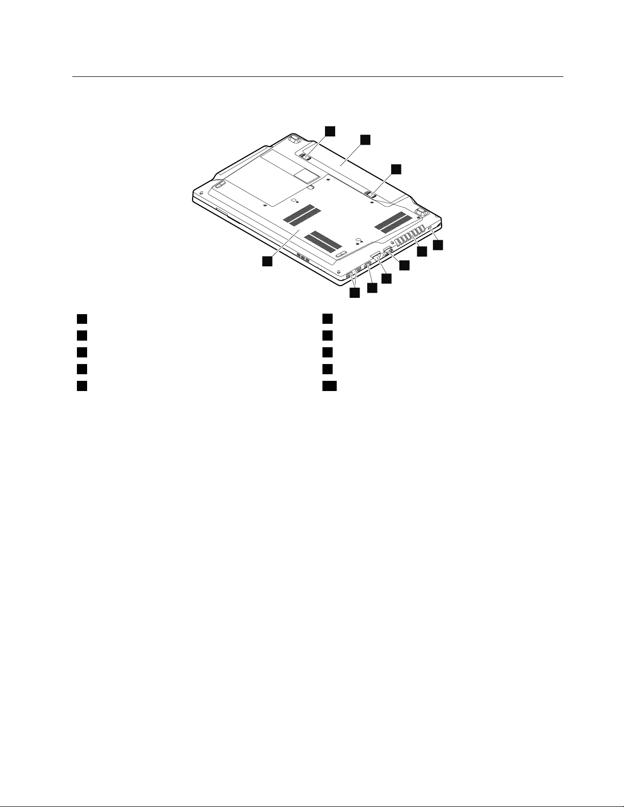
Bottomandleft-sideview
1
2
3
4
5
6
7
8
9
10
1Batterylatch(manual)
2Batterypack7RJ45Ethernetconnector
3Batterylatch(spring-loaded)
4Securitykeyhole9USB3.0connectors
5Fanlouvers10Bottomslotcover
1
Thememorymodules,harddiskdrive,andwirelesscardsarelocatedunderneaththebottomslotcover.
6Monitorconnector
8HDMIport
1
Figure3.ZhaoYangK49bottomandleft-sideview
Chapter8.Locations81
Page 88

82HardwareMaintenanceManual
Page 89

Chapter9.Partslist
Thischaptercontainsfollowinglistsoftheserviceparts.
•“Overall”onpage84
•“LCDFRUs”onpage86
•“Keyboard”onpage88
•“Miscellaneousparts”onpage88
•“acpoweradapters”onpage88
•“Powercords”onpage88
Notes:
•EachFRUisavailableforalltypesormodels,unlessotherwisespecied.
•ACRU(customerreplaceableunit)isidentiedbyasingleasterisk(*)ortwoasterisks(**)intheCRUIDcolumn.An
NintheCRUIDcolumnmeansthatthepartisnotaCRU.Asingleasterisk(*)meansthatthepartisaSelf-service
CRU;twoasterisks(**)meansthatthepartisanOptional-serviceCRU.
ExternalCRUstatementtocustomers:
Someproblemswithyourproductcanberesolvedwithareplacementpartyoucaninstallyourself,called
a“CustomerReplaceableUnit”or“CRU.”SomeCRUsaredesignatedasSelf-serviceCRUsandothersare
designatedasOptional-serviceCRUs.InstallationofSelf-serviceCRUsisyourresponsibility;youmayrequest
thatLenovoinstallsanOptional-serviceCRUaccordingtothewarrantyserviceforyourproduct.Whereyouare
installingtheCRU,LenovowillshiptheCRUtoyou.CRUinformationandreplacementinstructionsareshipped
withyourproductandareavailablefromLenovoatanytimeuponrequest.Y oumayndalistofCRUsinthe
publicationsthatshipwithyourproductorathttp://www.lenovo.com/CRUs.Y oumayberequiredtoreturnthe
defectivepartthatisreplacedbytheCRU.Whenreturnisrequired:(1)returninstructions,aprepaidshippinglabel,
andacontainerwillbeincludedwiththereplacementCRU;and(2)youmaybechargedforthereplacementCRUif
Lenovodoesnotreceivethedefectivepartwithinthirty(30)daysofyourreceiptofthereplacementCRU.Seeyour
LenovoLimitedWarrantydocumentationforfulldetails.
LenovocomputerscontainthefollowingtypesofCRUs:
–Self-serviceCRUs:TheseCRUsunplugorareheldbynomorethantwoscrews.Examplesofthesetypes
ofCRUsincludetheacpoweradapter,powercord,battery,andharddiskdrive.Otherself-serviceCRUs
dependingonproductdesignmightincludethememorymodule,wirelesscard,keyboard,andpalmrest
withngerprintreaderandtouchpad.
–Optional-serviceCRUs:TheseCRUsareisolatedpartswithinthecomputerthatareconcealedbyanaccess
panelthatistypicallysecuredbymorethantwoscrews.Oncetheaccesspanelisremoved,thespecic
CRUisvisible.
©CopyrightLenovo2012,2013
83
Page 90

Overall
1
2
a
4
3
b
5
c
d
6
8
7
e
f
9
h
10
i
11
g
j
k
12
13
14
15
16
17
18
19
20
21
Table3.Partslist—Overall
No.
FRU(Overall)
a-k
See“Miscellaneousparts”onpage88.
1
LCDunit(see“LCDFRUs”onpage86
)
2LLPPowerBoard90000350N
FRUNo.
CRU
ID
3LLPFunctionBoard90000351N
90201078N
4
LLPUpperCaseW/TP
5
LLPFingerPrintBoard90000349N
84HardwareMaintenanceManual
Page 91

Table3.Partslist—Overall(continued)
No.
FRU(Overall)
FRUNo.
6Batterypack,6cell,2.2Ah121500047
121500049
121500048
121500050
6Batterypack,6cell,2.8Ah121500052
121500053
7
LLPSpeakerL
8
LLPSpeakerR
9
LLPLowerCase
10
Opticaldrive,12.7mm,Rambo
90201084N
90201085N
90201073N
25201635
25201106
25201499
25201487
10Blankbezel101500142N
11LLPRAMDoor90201074N
12
SATAharddiskdrive,320G,5400rpm
16005211
16200068
16200097
12
SATAharddiskdrive,500G,5400rpm
16200067
16200118
16200090
16200098
12
SATAharddiskdrive,320G,7200rpm
16005030
16200194
16200092
16200099
12
SATAharddiskdrive,500G,7200rpm
16200124
16200195
16200100
12
SATAharddiskdrive,750G,5400rpm
16200119
16200121
16200192
12
SATAharddiskdrive,1TB,5400rpm
16200120
16200193
13
mSATAsolid-statedrive,16G
16200215
16200241
13
mSATAsolid-statedrive,128G
16200131
16200129
16200240
14
Intel6205NMOWMPCIENBHMCWLAN
14
Intel2230BGN+BTMPCIEHMCWlan
14
BroadcomBCM43228+BCM20702abgn&BT4.0
20002533N
20200078N
20200098
20200099
14
BroadcomBCM4313+BCM20702bgn&&BT4.0
20200100
20200101
14
CybertanBroadcomBCM43131x1BGNMOW
20200102N
CRU
ID
N
N
N
N
N
N
N
N
N
N
N
N
N
Chapter9.Partslist85
Page 92

Table3.Partslist—Overall(continued)
No.
FRU(Overall)
14
LiteonRealtek1x1BGNHMCWLANStockton
15Microprocessor1100365N
16
Memorymodule,2GB,DDRIII1600
16
Memorymodule,4GB,DDRIII1600
17
LLPMBDISN13P-NS2GW/HDMIWO/BT/3G
17
LLPMBW8DISN13P-NS12GWO/BT/3G
17
LLPMBW8PDISN13P-NS12GWO/BT/3G
18
LSSThermalModuleDIS,withFAN
19LLPMicrophone90201081N
20
Keyboard(see“Keyboard”onpage88)
—
acpoweradapter(see“acpoweradapters”onpage88
)
FRUNo.
20200016N
11200340
11200639
11200346
11200343
11200341
11200640
11200347
11200344
90000352N
90001428N
90001429N
90200874N
CRU
ID
N
N
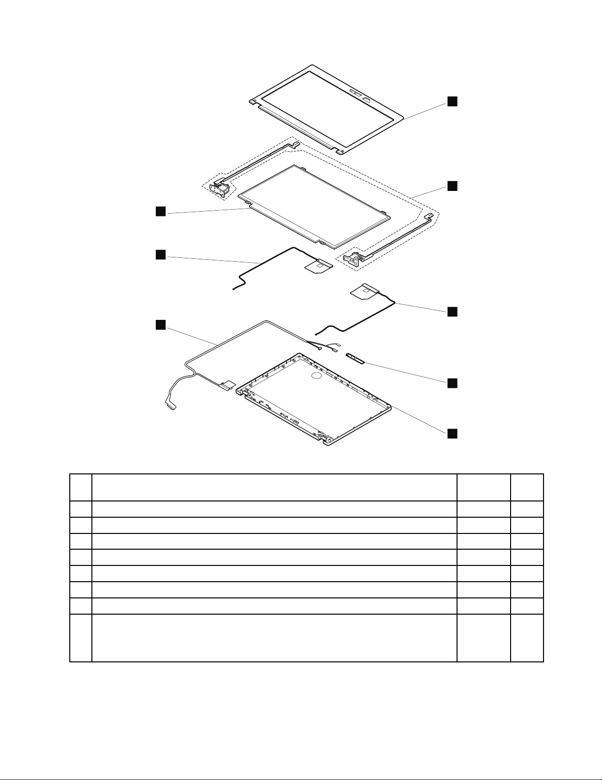
LCDFRUs
ZhaoYangK49modelsusea14-inch,high-denition(HD),light-emittingdiode(LED),liquid-crystaldisplay
(LCD).(T able4“Partslist-LCD”onpage87).
86HardwareMaintenanceManual
Page 93
1
2
3
4
5
6
8
7
Table4.Partslist-LCD
No.FRUFRUNo.
CRU
ID
1
LLPLCDBezelW/Camerahole
2LLPHingeL+R90201077N
3LLPAntennaR90201080N
4
LSSCamera1M
5
LLPLCDCoverW/Sponge
6
LLPLCDCable
7
LLPAntennaL90201079N
8
LCDmodule,14.0-inch,HD,anti-glair
90201072N
90000319N
90201071N
90201063N
18200240
N
18200238
18200237
18200239
Chapter9.Partslist87
Page 94

Keyboard
Table5.Partslist-Keyboard
Language
U.S.English
FRUNO.
(Windows7)
25203603
25203604
FRUNO.
(Windows
8)
25210002
25210003
25210004
Miscellaneousparts
Table6.Partslist-Systemmiscellaneousparts
FRUFRUNo.
(d)LSSFPBracket
(e)LLPDC-INBracket
(g)LLPUSBBracket
(i)LLPODDBracket
(j)LLPODDBezel
(k)LLPHDDBracket
LLPLCDBezelScrewPad
LLPScrewpack
CRUID
N
CRU
ID
90201001N
90201069N
90201068N
90201070N
90201075N
90201076N
90201082N
90201083N
Table7.Partslist-Cablemiscellaneousparts
FRUFRUNo.
(a)LLPPowerBoardCable
(b)LLPFunctionBoardCable
(c)LSSFPBoardCable
(f)LLPDC-INCable
(h)LLPUSBBoardCable
acpoweradapters
Table8.Partslist—acpoweradapters
FRUFRUNo.
3-pinadapter36001941
Powercords
ALenovopowercordforaspeciccountryorregionisusuallyavailableonlyinthatcountryorregion.
CRU
ID
90201064N
90201065N
90000318N
90201067N
90201066N
CRU
ID
N
36001927
36001942
88HardwareMaintenanceManual
Page 95

Table9.Partslist-3-pinpowercords
Countryorregion
China
FRUNo.
CRU
ID
145000600
N
145000568
145000538
Chapter9.Partslist89
Page 96

90HardwareMaintenanceManual
Page 97

AppendixA.Notices
Lenovomaynotoffertheproducts,services,orfeaturesdiscussedinthisdocumentinallcountries.Consult
yourlocalLenovorepresentativeforinformationontheproductsandservicescurrentlyavailableinyour
area.AnyreferencetoaLenovoproduct,program,orserviceisnotintendedtostateorimplythatonlythat
Lenovoproduct,program,orservicemaybeused.Anyfunctionallyequivalentproduct,program,orservice
thatdoesnotinfringeanyLenovointellectualpropertyrightmaybeusedinstead.However,itistheuser's
responsibilitytoevaluateandverifytheoperationofanyotherproduct,program,orservice.
Lenovomayhavepatentsorpendingpatentapplicationscoveringsubjectmatterdescribedinthis
document.Thefurnishingofthisdocumentdoesnotgiveyouanylicensetothesepatents.Youcansend
licenseinquiries,inwriting,to:
Lenovo(UnitedStates),Inc.
1009ThinkPlace-BuildingOne
Morrisville,NC27560
U.S.A.
Attention:LenovoDirectorofLicensing
LENOVOPROVIDESTHISPUBLICA TION“ASIS”WITHOUTWARRANTYOFANYKIND,EITHEREXPRESS
ORIMPLIED,INCLUDING,BUTNOTLIMITEDTO,THEIMPLIEDWARRANTIESOFNON-INFRINGEMENT,
MERCHANTABILITYORFITNESSFORAPARTICULARPURPOSE.Somejurisdictionsdonotallow
disclaimerofexpressorimpliedwarrantiesincertaintransactions,therefore,thisstatementmaynotapply
toyou.
Thisinformationcouldincludetechnicalinaccuraciesortypographicalerrors.Changesareperiodically
madetotheinformationherein;thesechangeswillbeincorporatedinneweditionsofthepublication.
Lenovomaymakeimprovementsand/orchangesintheproduct(s)and/ortheprogram(s)describedinthis
publicationatanytimewithoutnotice.
Theproductsdescribedinthisdocumentarenotintendedforuseinimplantationorotherlifesupport
applicationswheremalfunctionmayresultininjuryordeathtopersons.Theinformationcontainedinthis
documentdoesnotaffectorchangeLenovoproductspecicationsorwarranties.Nothinginthisdocument
shalloperateasanexpressorimpliedlicenseorindemnityundertheintellectualpropertyrightsofLenovo
orthirdparties.Allinformationcontainedinthisdocumentwasobtainedinspecicenvironmentsandis
presentedasanillustration.Theresultobtainedinotheroperatingenvironmentsmayvary.
Lenovomayuseordistributeanyoftheinformationyousupplyinanywayitbelievesappropriatewithout
incurringanyobligationtoyou.
Anyreferencesinthispublicationtonon-LenovoWebsitesareprovidedforconvenienceonlyanddonotin
anymannerserveasanendorsementofthoseWebsites.ThematerialsatthoseWebsitesarenotpartof
thematerialsforthisLenovoproduct,anduseofthoseWebsitesisatyourownrisk.
Anyperformancedatacontainedhereinwasdeterminedinacontrolledenvironment.Therefore,theresult
obtainedinotheroperatingenvironmentsmayvarysignicantly.Somemeasurementsmayhavebeen
madeondevelopment-levelsystemsandthereisnoguaranteethatthesemeasurementswillbethesame
ongenerallyavailablesystems.Furthermore,somemeasurementsmayhavebeenestimatedthrough
extrapolation.Actualresultsmayvary.Usersofthisdocumentshouldverifytheapplicabledatafortheir
specicenvironment.
©CopyrightLenovo2012,2013
91
Page 98

Electronicemissionsnotices
ForelectronicemissioninformationonClassBdigitaldevices,refertothecorrespondinginformationin
theUserGuide.
EUcontact:Lenovo,Einsteinova21,85101Bratislava,Slovakia
Trademarks
ThefollowingtermsaretrademarksofLenovointheUnitedStates,othercountriesorboth:
ActiveProtectionSystem
Lenovo
OneKey
WindowsisthetrademarkoftheMicrosoftgroupofcompanies.
IntelisthetrademarkofIntelCorporationoritssubsidiariesintheUnitedStates,othercountries,orboth.
Othercompany,product,orservicenamesmaybethetrademarksorservicemarksofothers.
92HardwareMaintenanceManual
Page 99

Page 100

 Loading...