

Page 1

HardwareMaintenanceManual
LenovoZhaoYangK4350andK4350A
Page 2

Note:Beforeusingthisinformationandtheproductitsupports,besuretoreadthegeneralinformation
underAppendixA“Notices”onpage73
.
FirstEdition(April2013)
©CopyrightLenovo2013.
LIMITEDANDRESTRICTEDRIGHTSNOTICE:IfdataorsoftwareisdeliveredpursuantaGeneralServicesAdministration
“GSA”contract,use,reproduction,ordisclosureissubjecttorestrictionssetforthinContractNo.GS-35F-05925.
Page 3

Contents
Aboutthismanual...........iii
Chapter1.Safetyinformation......1
Generalsafety................1
Electricalsafety...............1
Safetyinspectionguide............3
Handlingdevicesthataresensitivetoelectrostatic
discharge..................3
Groundingrequirements............4
Safetynotices(multilingualtranslations)......4
Chapter2.Generalcheckout.....21
Whattodorst..............21
Powersystemcheckout...........22
Checkingtheacpoweradapter......22
Checkingoperationalcharging......23
Checkingthebatterypack........23
Chapter3.Importantservice
information..............25
Recoveringthecomputersettings.......25
Usingpasswords..............25
Powermanagement............26
Screenblankmode...........26
Sleepmode..............26
Hibernationmode...........27
Chapter4.Statusindicators.....29
Chapter5.Fnkeycombinations...31
Chapter6.Locations.........33
Locatingcomputercontrols,connectors,and
indicators.................33
Frontview...............33
Bottomview..............34
LocatingFRUsandCRUs..........34
MajorFRUsandCRUs..........35
LCDFRUsandCRUs..........36
LookingupFRUinformation.........37
Chapter7.FRUreplacement
notices................39
ImportantnoticeforreplacingFRUs......39
Screwnotices...............40
Chapter8.Removingorreplacinga
FRU..................41
Generalguidelines.............41
1010Batterypack.............42
1020Bottomslotcover...........42
1030Memorymodules...........43
1040Harddiskdriveassembly........45
1050PCIExpressMiniCardforwirelessLAN..46
1060mSAT Asolid-statedrive.........47
1070Backupbattery............48
1080Keyboard..............49
1090Keyboardbezel............51
1110Fingerprintboardbracketandngerprint
boardwithcable..............54
1120Powerboard.............55
1130Mediacardreaderslotboard.......55
1140Systemboardassembly.........57
1150Thermalmoduleassembly........60
1160Speakers,LCDunitandbasecover....62
1170DC-inconnector............66
2010LCDfrontbezel............67
2020Cameraandmicrophoneboard......67
2030LCDpanel,LCDcable,andhinges....68
2040AntennaassemblyandLCDrearcover...70
AppendixA.Notices..........73
Trademarks................74
©CopyrightLenovo2013
i
Page 4

iiHardwareMaintenanceManual
Page 5

Aboutthismanual
ThismanualprovidesserviceandreferenceinformationforthefollowingLenovo
Machine
LenovoZhaoYangK4350andK4350A20228
MachineType(MT)
®
products.
Thismanualprovidesinformationaboutthecomputerfeatures,specications,componentlocations,
hardwarereplacementprocedures,andpartslisting.Thismanualalsoincludessafetyguidelinesand
importantnoticesforservicingthecomputer.
Important:
•ThismanualisintendedonlyfortrainedservicetechnicianswhoarefamiliarwithLenovoproducts.Use
thismanualtotroubleshootproblemseffectively.
•BeforeservicingaLenovoproduct,ensurethatyoureadalltheinformationinChapter1“Safety
information”onpage1
andChapter3“Importantserviceinformation”onpage25.
©CopyrightLenovo2013
iii
Page 6

ivHardwareMaintenanceManual
Page 7

Chapter1.Safetyinformation
Thischapterpresentsthefollowingsafetyinformationthatyouneedtobefamiliarwithbeforeyouservicea
Lenovonotebookcomputer.
•“Generalsafety”onpage1
•“Electricalsafety”onpage1
•“Safetyinspectionguide”onpage3
•“Handlingdevicesthataresensitivetoelectrostaticdischarge”onpage3
•“Groundingrequirements”onpage4
•“Safetynotices(multilingualtranslations)”onpage4
Generalsafety
Followtheserulestoensuregeneralsafety:
•Observegoodhousekeepingintheareaofthemachinesduringandaftermaintenance.
•Whenliftinganyheavyobject:
1.Makesurethatyoucanstandsafelywithoutslipping.
2.Distributetheweightoftheobjectequallybetweenyourfeet.
3.Useaslowliftingforce.Nevermovesuddenlyortwistwhenyouattempttolift.
4.Liftbystandingorbypushingupwithyourlegmuscles;thisactionremovesthestrainfromthe
musclesinyourback.Donotattempttoliftanyobjectthatweighsmorethan16kg(35lb)orthatyou
thinkistooheavyforyou.
•Donotperformanyactionthatcauseshazardstothecustomer,orthatmakestheequipmentunsafe.
•Beforeyoustartthemachine,makesurethatotherservicetechniciansandthecustomer'spersonnelare
notinahazardousposition.
•Placeremovedcoversandotherpartsinasafeplace,awayfromallpersonnel,whileyouareservicing
themachine.
•Keepyourtoolcaseawayfromwalkareassothatotherpeoplewillnottripoverit.
•Donotwearlooseclothingthatcanbetrappedinthemovingpartsofamachine.Makesurethatyour
sleevesarefastenedorrolledupaboveyourelbows.Ifyourhairislong,fastenit.
•Inserttheendsofyournecktieorscarfinsideclothingorfastenitwithanonconductiveclip,about8
centimeters(3inches)fromtheend.
•Donotwearjewelry,chains,metal-frameeyeglasses,ormetalfastenersforyourclothing,becausemetal
objectsaregoodelectricalconductors.
•Wearsafetyglasseswhenyouarehammering,drilling,soldering,cuttingwire,attachingsprings,using
solvents,orworkinginanyotherconditionsthatmightbehazardoustoyoureyes.
•Afterservice,reinstallallsafetyshields,guards,labels,andgroundwires.Replaceanysafetydevice
thatiswornordefective.
•Reinstallallcoverscorrectlybeforereturningthemachinetothecustomer.
•Fanlouversonthemachinehelptopreventoverheatingofinternalcomponents.Donotobstructfan
louversorcoverthemwithlabelsorstickers.
Electricalsafety
Observethefollowingruleswhenworkingonelectricalequipment.
©CopyrightLenovo2013
1
Page 8

Important:
Useonlyapprovedtoolsandtestequipment.Somehandtoolshavehandlescoveredwithasoftmaterial
thatdoesnotinsulateyouwhenworkingwithliveelectricalcurrents.
Manycustomershave,neartheirequipment,rubberoormatsthatcontainsmallconductivebersto
decreaseelectrostaticdischarges.Donotusethistypeofmattoprotectyourselffromelectricalshock.
•Findtheroomemergencypower-off(EPO)switch,disconnectingswitch,orelectricaloutlet.Ifanelectrical
accidentoccurs,youcanthenoperatetheswitchorunplugthepowercordquickly.
•Donotworkaloneunderhazardousconditionsornearequipmentthathashazardousvoltages.
•Disconnectallpowerbefore:
–Performingamechanicalinspection
–Workingnearpowersupplies
–Removingorinstallingmainunits
•Beforeyoustarttoworkonthemachine,unplugthepowercord.Ifyoucannotunplugit,askthecustomer
topower-offthewallboxthatsuppliespowertothemachine,andtolockthewallboxintheoffposition.
•Ifyouneedtoworkonamachinethathasexposedelectricalcircuits,observethefollowingprecautions:
–Ensurethatanotherperson,familiarwiththepower-offcontrols,isnearyou.
Attention:Anotherpersonmustbetheretoswitchoffthepower,ifnecessary.
–Useonlyonehandwhenworkingwithpowered-onelectricalequipment;keeptheotherhandinyour
pocketorbehindyourback.
Attention:Anelectricalshockcanoccuronlywhenthereisacompletecircuit.Byobservingtheabove
rule,youmaypreventacurrentfrompassingthroughyourbody.
–Whenusingtesters,setthecontrolscorrectlyandusetheapprovedprobeleadsandaccessoriesfor
thattester.
–Standonsuitablerubbermats(obtainedlocally,ifnecessary)toinsulateyoufromgroundssuchas
metaloorstripsandmachineframes.
Observethespecialsafetyprecautionswhenyouworkwithveryhighvoltages;Instructionsforthese
precautionsareinthesafetysectionsofmaintenanceinformation.Useextremecarewhenmeasuring
highvoltages.
•Regularlyinspectandmaintainyourelectricalhandtoolsforsafeoperationalcondition.
•Donotusewornorbrokentoolsandtesters.
•Neverassumethatpowerhasbeendisconnectedfromacircuit.First,checkthatithasbeenpoweredoff.
•Alwayslookcarefullyforpossiblehazardsinyourworkarea.Examplesofthesehazardsaremoistoors,
nongroundedpowerextensioncables,powersurges,andmissingsafetygrounds.
•Donottouchliveelectricalcircuitswiththereectivesurfaceofaplasticdentalmirror.Thesurfaceis
conductive;suchtouchingcancausepersonalinjuryandmachinedamage.
•Donotservicethefollowingpartswiththepoweronwhentheyareremovedfromtheirnormaloperating
placesinamachine:
–Powersupplyunits
–Pumps
–Blowersandfans
–Motorgenerators
–Similarunitstolistedabove
Thispracticeensurescorrectgroundingoftheunits.
•Ifanelectricalaccidentoccurs:
–Usecaution;donotbecomeavictimyourself.
–Switchoffpower.
–Sendanotherpersontogetmedicalaid.
2HardwareMaintenanceManual
Page 9

Safetyinspectionguide
Thepurposeofthisinspectionguideistoassistyouinidentifyingpotentiallyunsafeconditions.Aseach
machinewasdesignedandbuilt,requiredsafetyitemswereinstalledtoprotectusersandservicetechnicians
frominjury.Thisguideaddressesonlythoseitems.Y oushouldusegoodjudgmenttoidentifypotential
safetyhazardsduetoattachmentofnon-Lenovofeaturesoroptionsnotcoveredbythisinspectionguide.
Ifanyunsafeconditionsarepresent,youmustdeterminehowserioustheapparenthazardcouldbeand
whetheryoucancontinuewithoutrstcorrectingtheproblem.
Considertheseconditionsandthesafetyhazardstheypresent:
•Electricalhazards,especiallyprimarypower(primaryvoltageontheframecancauseseriousorfatal
electricalshock)
•Explosivehazards,suchasadamagedCRTfaceorabulgingcapacitor
•Mechanicalhazards,suchaslooseormissinghardware
Todeterminewhetherthereareanypotentiallyunsafeconditions,usethefollowingchecklistatthebeginning
ofeveryservicetask.Beginthecheckswiththepoweroff,andthepowercorddisconnected.
Checklist:
1.Checkexteriorcoversfordamage(loose,broken,orsharpedges).
2.Poweroffthecomputer.Disconnectthepowercord.
3.Checkthepowercordfor:
a.Athird-wiregroundconnectoringoodcondition.Useametertomeasurethird-wireground
continuityfor0.1ohmorlessbetweentheexternalgroundpinandtheframeground.
b.Thepowercordshouldbethetypespeciedinthepartslist.
c.Insulationmustnotbefrayedorworn.
4.Checkforcrackedorbulgingbatteries.
5.Removethecover.
6.Checkforanyobviousnon-Lenovoalterations.Usegoodjudgmentastothesafetyofanynon-Lenovo
alterations.
7.Checkinsidetheunitforanyobviousunsafeconditions,suchasmetallings,contamination,wateror
otherliquids,orsignsofreorsmokedamage.
8.Checkforworn,frayed,orpinchedcables.
9.Checkthatthepower-supplycoverfasteners(screwsorrivets)havenotbeenremovedortamperedwith.
Handlingdevicesthataresensitivetoelectrostaticdischarge
Anycomputerpartcontainingtransistorsorintegratedcircuits(ICs)shouldbeconsideredsensitiveto
electrostaticdischarge(ESD).ESDdamagecanoccurwhenthereisadifferenceinchargebetweenobjects.
ProtectagainstESDdamagebyequalizingthechargesothatthemachine,thepart,theworkmat,andthe
personhandlingthepartareallatthesamecharge.
Notes:
1.Useproduct-specicESDprocedureswhentheyexceedtherequirementsnotedhere.
2.MakesurethattheESDprotectivedevicesyouusehavebeencertied(ISO9000)asfullyeffective.
WhenhandlingESD-sensitiveparts:
Chapter1.Safetyinformation3
Page 10
•Keepthepartsinprotectivepackagesuntiltheyareinsertedintotheproduct.
•Avoidcontactwithotherpeople.
•Wearagroundedwriststrapagainstyourskintoeliminatestaticonyourbody.
•Preventthepartfromtouchingyourclothing.Mostclothingisinsulativeandretainsachargeevenwhen
youarewearingawriststrap.
•Useagroundedworkmattoprovideastatic-freeworksurface.Thematisespeciallyusefulwhen
handlingESD-sensitivedevices.
•Selectagroundingsystem,suchasthoselistedbelow,toprovideprotectionthatmeetsthespecic
servicerequirement.
Note:TheuseofagroundingsystemtoguardagainstESDdamageisdesirablebutnotnecessary.
–AttachtheESDgroundcliptoanyframeground,groundbraid,orgreen-wireground.
–Whenworkingonadouble-insulatedorbattery-operatedsystem,useanESDcommongroundor
referencepoint.Y oucanusecoaxorconnector-outsideshellsonthesesystems.
–Usetheroundgroundprongoftheacplugonac-operatedcomputers.
Groundingrequirements
Electricalgroundingofthecomputerisrequiredforoperatorsafetyandcorrectsystemfunction.Proper
groundingoftheelectricaloutletcanbeveriedbyacertiedelectrician.
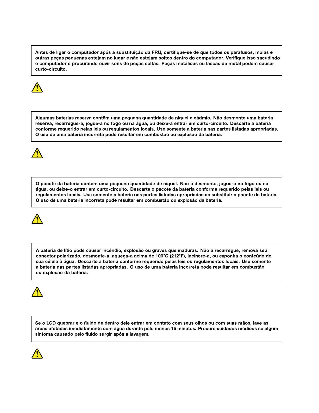
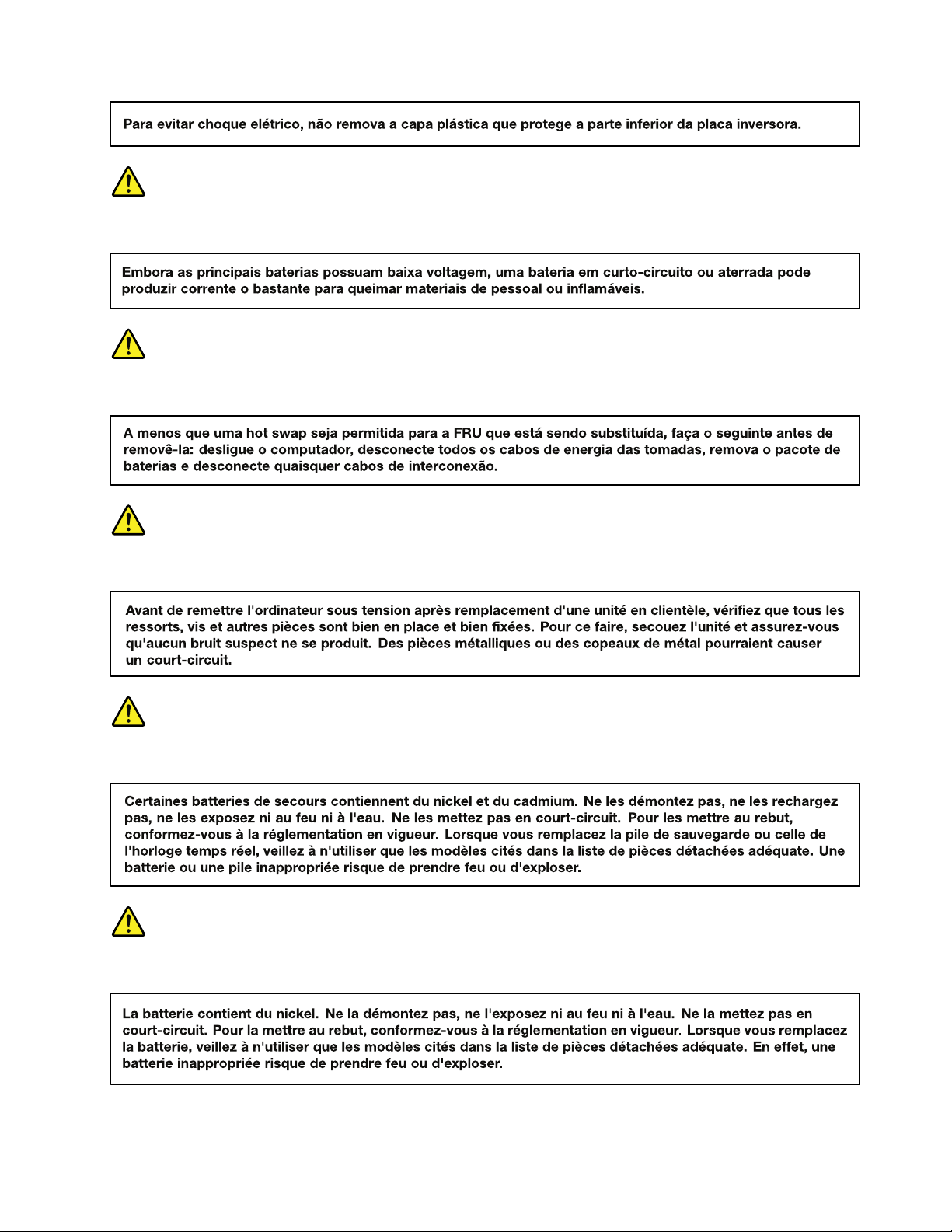
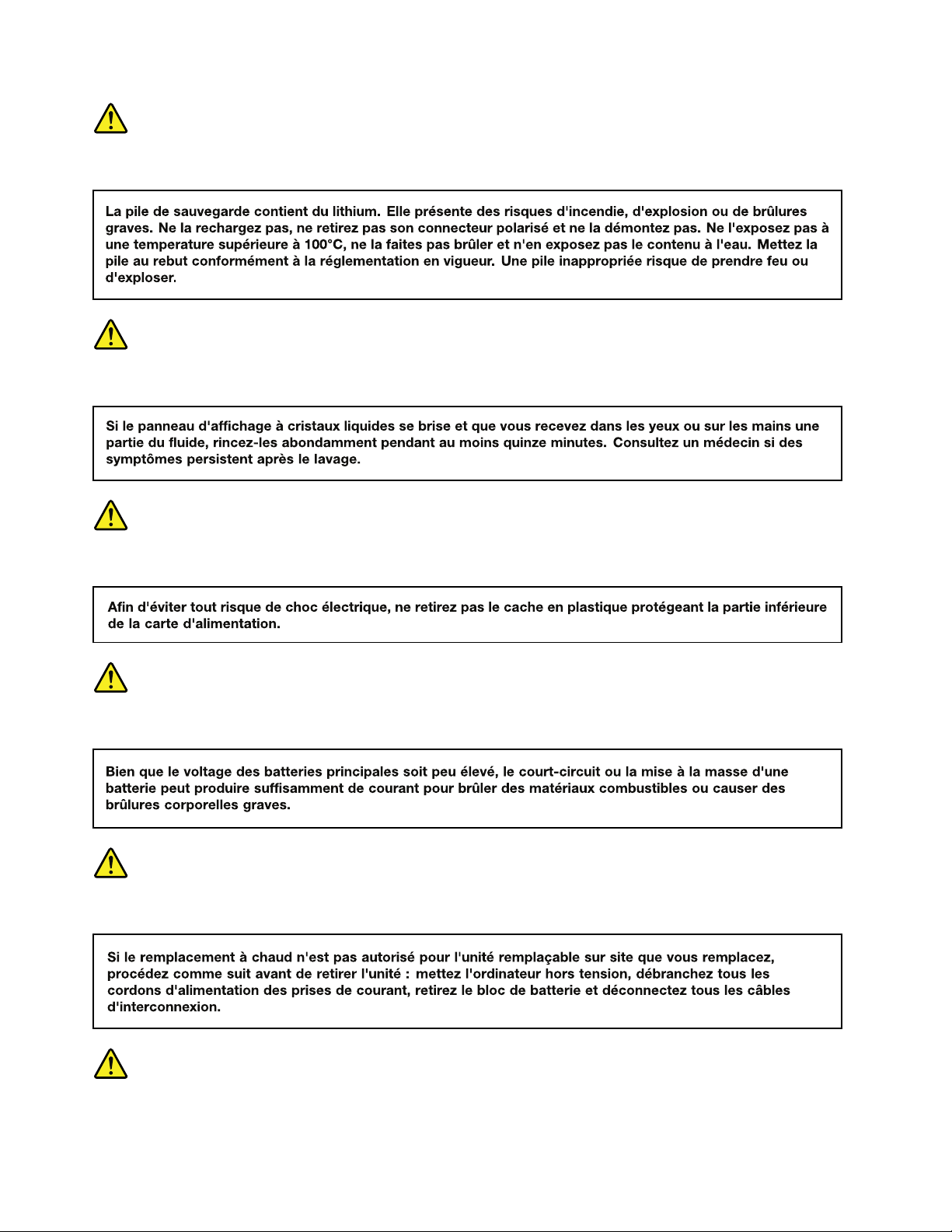
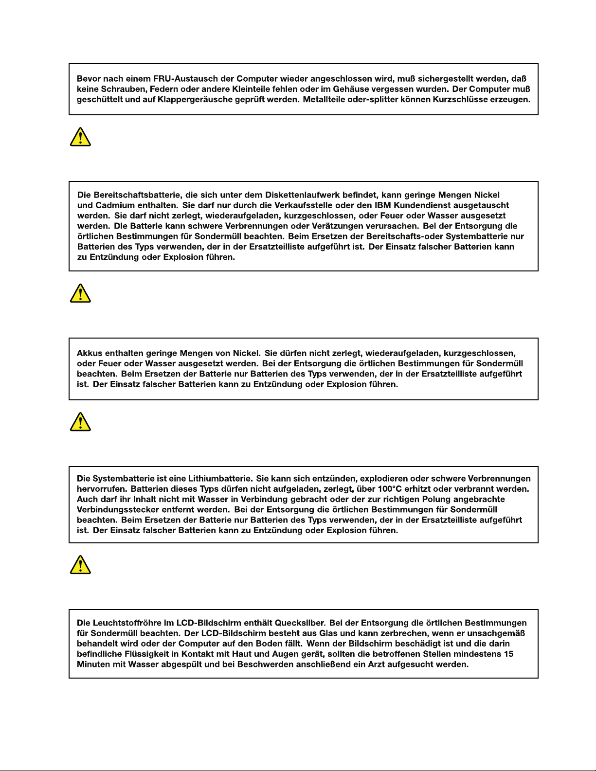
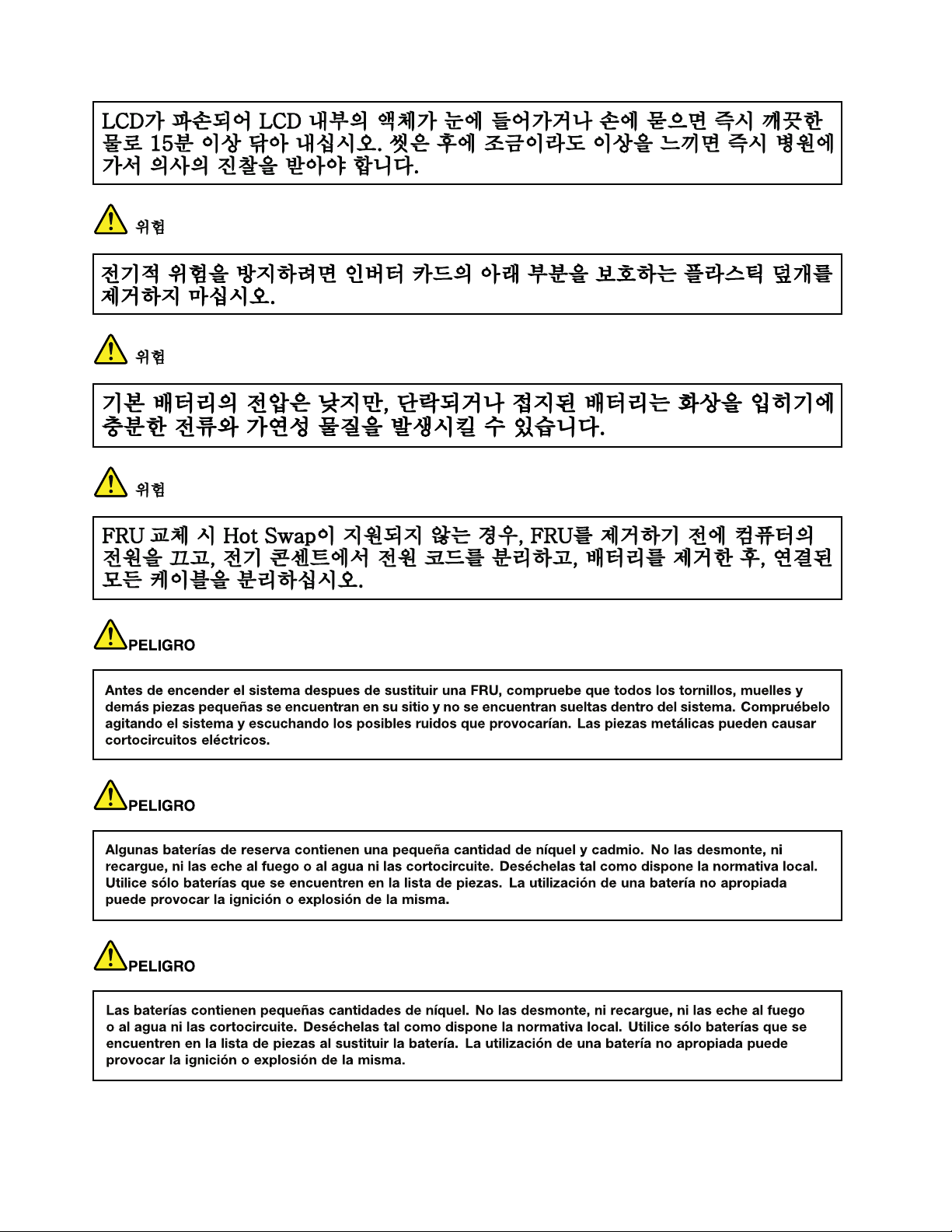
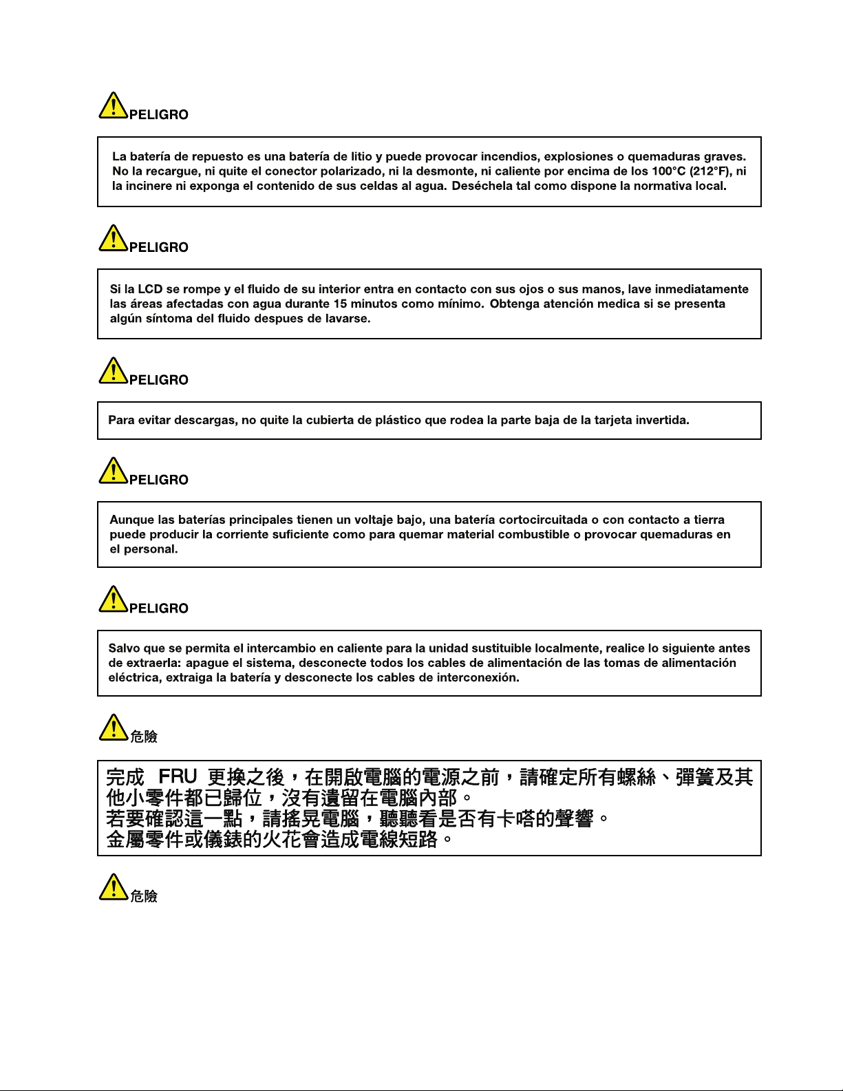
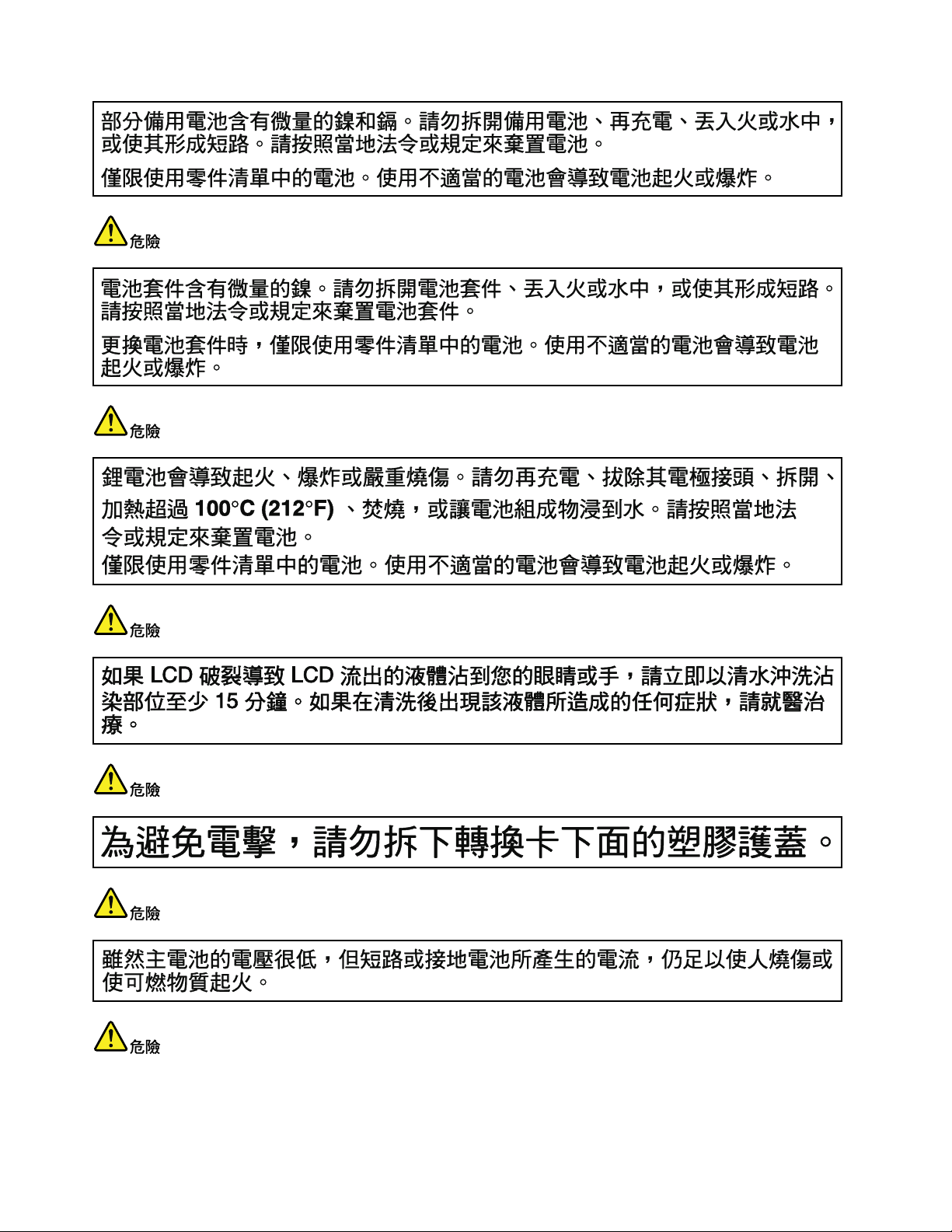
Safetynotices(multilingualtranslations)
Thesafetynoticesinthissectionareprovidedinthefollowinglanguages:
•English
•Arabic
•BrazilianPortuguese
•French
•German
•Hebrew
•Japanese
•Korean
•Spanish
•T raditionalChinese
DANGER
DANGER
4HardwareMaintenanceManual
Page 11
DANGER
DANGER
DANGER
DANGER
DANGER
Chapter1.Safetyinformation5
Page 12
DANGER
6HardwareMaintenanceManual
Page 13
Chapter1.Safetyinformation7
Page 14
PERIGO
PERIGO
PERIGO
PERIGO
PERIGO
PERIGO
8HardwareMaintenanceManual
Page 15
PERIGO
PERIGO
DANGER
DANGER
DANGER
Chapter1.Safetyinformation9
Page 16
DANGER
DANGER
DANGER
DANGER
DANGER
VORSICHT
10HardwareMaintenanceManual
Page 17
VORSICHT
VORSICHT
VORSICHT
VORSICHT
Chapter1.Safetyinformation11
Page 18
VORSICHT
VORSICHT
VORSICHT
12HardwareMaintenanceManual
Page 19
Chapter1.Safetyinformation13
Page 20
14HardwareMaintenanceManual
Page 21
Chapter1.Safetyinformation15
Page 22
16HardwareMaintenanceManual
Page 23
Chapter1.Safetyinformation17
Page 24
18HardwareMaintenanceManual
Page 25

Chapter1.Safetyinformation19
Page 26

20HardwareMaintenanceManual
Page 27

Chapter2.Generalcheckout
Thischaptercontainsthefollowingtopics:
•“Whattodorst”onpage21
•“Powersystemcheckout”onpage22
Beforeyougotothecheckoutinstructions,ensurethatyoureadthefollowingimportantnotes.
Importantnotes:
•Onlycertiedtrainedpersonnelshouldservicethecomputer.
•BeforereplacinganyFRU,readtheentirepageonremovingandreplacingFRUs.
•WhenyoureplaceFRUs,itisrecommendedtousenewnylon-coatedscrews.
•Beextremelycarefulduringsuchwriteoperationsascopying,saving,orformatting.Drivesinthecomputer
thatyouareservicingsequencemighthavebeenaltered.Ifyouselectanincorrectdrive,dataorprograms
mightbeoverwritten.
•ReplaceaFRUonlywithanotherFRUofthecorrectmodel.WhenyoureplaceaFRU,makesurethatthemodel
ofthemachineandtheFRUpartnumberarecorrectbyreferringtotheFRUpartslist.
•AFRUshouldnotbereplacedbecauseofasingle,unreproduciblefailure.Singlefailurescanoccurfora
varietyofreasonsthathavenothingtodowithahardwaredefect,suchascosmicradiation,electrostaticdischarge,
orsoftwareerrors.ConsiderreplacingaFRUonlywhenaproblemrecurs.IfyoususpectthataFRUisdefective,
cleartheerrorlogandrunthetestagain.Iftheerrordoesnotrecur,donotreplacetheFRU.
•BecarefulnottoreplaceanondefectiveFRU.
Whattodorst
WhenyoudoreturnaFRU,youmustincludethefollowinginformationinthepartsexchangeformor
partsreturnformthatyouattachtoit:
•Nameandphonenumberoftheservicetechnician
•Dateofservice
•Dateonwhichthemachinefailed
•Dateofpurchase
•ProcedureindexandnumberofthepageonwhichthefailingFRUwasdetected
•NameandpartnumberofthefailingFRU
•Machinetype,modelnumber,andserialnumber
•Nameandaddressofthecustomer
Note:Duringthewarrantyperiod,thecustomermayberesponsibleforrepaircostsifthecomputerdamage
wascausedbymisuse,accident,modication,unsuitablephysicaloroperatingenvironment,orimproper
maintenancebythecustomer.Followingisalistofsomecommonitemsthatarenotcoveredunderwarranty
andsomesymptomsthatmightindicatethatthesystemwassubjectedtostressbeyondnormaluse.
Beforecheckingproblemswiththecomputer,determinewhetherthedamageiscoveredunderthewarranty
byreferringtothefollowinglist:
Thefollowingarenotcoveredunderwarranty:
•LCDpanelcrackedfromtheapplicationofexcessiveforceorfrombeingdropped
•Scratched(cosmetic)parts
•Distortion,deformation,ordiscolorationofthecosmeticparts
•Plasticparts,latches,pins,orconnectorsthathavebeencrackedorbrokenbyexcessiveforce
•Damagecausedbytheliquidspilledintothecomputer
•DamagecausedbytheimproperinsertionofaPCcardortheinstallationofanincompatiblecard
©CopyrightLenovo2013
21
Page 28

•Improperdiscinsertionoruseofanopticaldrive
(20V)
1
3
2
•Diskettedrivedamagecausedbypressureonthediskettedrivecover,foreignmaterialinthedrive,
ortheinsertionofadiskettewithmultiplelabels
•Damagedorbentdisketteejectbutton
•Fusesblownbyattachmentofanunsupporteddevice
•Forgottencomputerpassword(makingthecomputerunusable)
•Stickykeyscausedbyspillingliquidontothekeyboard
•Useofanincorrectacpoweradapteronnotebookcomputers
Thefollowingsymptomsmightindicatedamagecausedbynonwarrantedactivities:
•Missingpartsmightbeasymptomofunauthorizedserviceormodication.
•Ifthespindleofaharddiskdrivebecomesnoisy,itmayhavebeensubjectedtoexcessiveforce,
ordropped.
Powersystemcheckout
Toverifyapowersymptom,dothefollowing:
1.T urnoffthecomputer.
2.Removethebatterypack.
3.Connecttheacpoweradapter.
4.Checkthatpowerissuppliedwhenyouturnonthecomputer.
5.T urnoffthecomputer.
6.Disconnecttheacpoweradapterandinstallthechargedbatterypack.
7.Checkthatthebatterypacksuppliespowerwhenyouturnonthecomputer.
Ifyoususpectapowerproblem,refertothefollowingtopicsforacheckout:
•“Checkingtheacpoweradapter”onpage22
•“Checkingoperationalcharging”onpage23
•“Checkingthebatterypack”onpage23
Checkingtheacpoweradapter
Ifthecomputerfailsonlywhentheacpoweradapterisused,refertotheinformationinthistopictocheck
theacpoweradapter.
•Ifthepower-onindicatordoesnotturnon,checkthepowercordoftheacpoweradapterforcorrect
continuityandinstallation.
•Ifthecomputerdoesnotchargeduringoperation,goto“Checkingoperationalcharging”onpage23
Tochecktheacpoweradapter,dothefollowing:
1.Unplugtheacpoweradaptercablefromthecomputer.
2.Measuretheoutputvoltageacrosstheplugoftheacpoweradaptercable.Thecorrectvoltagesare
showninthefollowingtable.
Pin
1+20
20
3
Voltage(Vdc)
Ground
.
Note:Theoutputvoltageacrosspin2mightdifferfromthevoltagethatyoumeasure.
3.Dependingonthevoltagethatyoumeasure,dooneofthefollowing:
•Ifthevoltageisnotcorrect,replacetheacpoweradapter.
22HardwareMaintenanceManual
Page 29

•Ifthevoltageisacceptable,dothefollowing:
1(+)
2(+)
5
4
3
6(-)
7(-)
a.Replacethesystemboard.
b.Iftheproblempersists,calltheCustomerSupportCenter.
Note:Noisefromtheacpoweradapterdoesnotalwaysindicateadefect.
Checkingoperationalcharging
Tocheckwhetherthebatterypackchargesproperlyduringoperation,dothefollowing:
Note:Beforeyoubegin,installadischargedbatterypackorabatterypackthathaslessthan50%ofthe
totalpowerremaininginthecomputer.
1.Ifthebatterystatusindicatordoesnotturnon,removethebatterypackandletitreturntoroom
temperature.
2.Reinstallthebatterypack.
3.Iftheindicatorstilldoesnotturnon,replacethebatterypack.
4.Iftheindicatorstilldoesnotturnon,replacethesystemboard.Otherwise,referto“Checkingthebattery
pack”onpage23tochecktheoriginalbatterypack.
Checkingthebatterypack
ThebatterystatusiconintheMicrosoft
®
Windows
powerremaining.
TocheckdetailedbatterystatusinformationontheWindowsoperatingsystems,dothefollowing:
®
noticationareadisplaysthepercentageofbattery
•Windows7:LaunchthePowerManagerprogramandclicktheBatterytab.
•Windows8:Dooneofthefollowing:
–ClickStart➙LenovoSolutionCenter➙System➙Battery.
–LaunchtheLenovoSettingsprogramfromtheStartscreen,andthenclickPower.
Tocheckthebatterypack,dothefollowing:
1.T urnoffthecomputeranddisconnecttheacpoweradapter.
2.Removethebatterypackandmeasurethevoltagebetweenbatteryterminals1(+)and7(-).The
correctvoltagesareshowninthefollowingtable.
Terminal
1+0to+14
7
Voltage(Vdc)
Ground(-)
3.Measuretheresistancebetweenbatteryterminals5and7.Theresistanceshouldbe4to30KΩ.Ifthe
resistanceisnotcorrect,replacethebatterypack.
4.Dependingonthevoltagethatyoumeasure,dooneofthefollowing:
•Ifthevoltageislessthan+12.0Vdc,rechargethebatterypack.Ifthevoltagestillislessthan+12.0V
dcafterrecharging,replacethebatterypack.
Chapter2.Generalcheckout23
Page 30

•Ifthevoltageismorethan+12.0Vdc,dischargethebatterypackuntilthevoltagebecomesless
than+12.0Vdcandthenrechargethebatterypack.Ifthevoltagestillislessthan+12.0Vdcafter
recharging,replacethebatterypack.
Note:Rechargingwilltakeatleastthreehours,evenifthebatterystatusindicatordoesnotturnon.
5.Replacethesystemboardifthenewbatterypackisnotcharged.
24HardwareMaintenanceManual
Page 31

Chapter3.Importantserviceinformation
Thischapterpresentsthefollowinginformation:
•“Recoveringthecomputersettings”onpage25
•“Usingpasswords”onpage25
•“Powermanagement”onpage26
Recoveringthecomputersettings
Thistopicprovidesinformationabouttherecoveryprogramsthatareavailableforyoutorecoverthe
computersettings.
•Windows7:ThefollowingrecoveryprogramsareavailableoncomputerswithaWindows7operating
system:
–OneKey
TheOneKeyRecoveryProprogramenablesyoutobackupallyourharddiskdrivecontents,including
theoperatingsystem,datales,softwareprograms,andpersonalsettings.Y oucandesignatewhere
theOneKeyRecoveryProprogramstoresthebackup.Afteryouhavebackedupthecontentsonthe
harddiskdrive,youcanrestorethecompletecontentsoftheharddiskdrive,restoreonlythedesired
les,orrestoreonlytheWindowsoperatingsystemandapplications.
–ProductRecovery
TheProductRecoveryprogramenablesyoutorestorethecomputersettingstothefactorydefault
settingsthroughrecoverymedia.
®
RecoveryPro
Attention:WhenyouusetheProductRecoveryprogramtorestorethecomputersettings,allthedata
youhavestoredontheharddiskdrivewillbedeletedandthecomputersettingswillberestoredtothe
factorydefaultsettings.Duringtherestoringprocess,youwillbegiventheoptiontosaveoneormore
lescurrentlyontheharddiskdrivetoothermediabeforethedataisdeleted.
•Windows8:ThepreinstalledWindowsrecoveryprogramenablesyoutodothefollowing:
–Refreshingthecomputerwithoutlosingpersonalles
–Restoringthecomputertothefactorydefaultsettings
Attention:WhenyouusetheWindowsrecoveryprogramtorestorethecomputersettings,allthedata
youhavestoredontheharddiskdrivewillbedeletedandthecomputerwillberestoredtothefactory
defaultsettings.Toavoiddataloss,backupyourdatainadvance.
–Conguringtheadvancedstartupoptions
Theadvancedstartupoptionsenableyoutodothefollowing:
–ChangingthestartupsettingsoftheWindowsoperatingsystem
–RestoringtheWindowsoperatingsystemfromasystemimage
–Startingupfromanexternaldevice
Formoreinformationabouttherecoverysolutions,refertothehelpinformationsystemoftheprograms.
Usingpasswords
Youcansetthefollowingtypesofpasswordstoprotectunauthorizedaccesstoyourcomputer.
©CopyrightLenovo2013
25
Page 32

Attention:Ifyouforgetthepassword,thereisnoserviceproceduretoresetthepassword.Thesystem
boardmustbereplacedforascheduledfee.
•Power-onpassword:Apower-onpasswordprotectsthecomputerfrombeingturnedonbyan
unauthorizedperson.Ifapower-onpasswordhasbeenset,theusermustenterthepasswordbefore
startingtheoperatingsystem.
•Supervisorpassword:AsupervisorpasswordprotectsthesysteminformationstoredintheBIOS
program.TheusermustenterthesupervisorpasswordtogetaccesstotheBIOSprogramandchange
systemcongurations.
Ifyouhavesetapassword,youwillbepromptedtoenterthepasswordwheneveryouturnonthecomputer.
Powermanagement
Therearethreepowermanagementmodestoreducepowerconsumption:screenblank,sleep,and
hibernation.
Screenblankmode
Inthefollowingcircumstances,thecomputerentersscreenblankmode:
•Thetimesetonthe“T urnoffmonitor”timerontheWindows7operatingsystemexpires.
Toendscreenblankmodeandresumenormaloperation,pressanykey.
•Y ouhavepressedFn+F2.
Toendscreenblankmodeandresumenormaloperation,pressFn+F2.
Sleepmode
Whenthecomputerenterssleepmode,thefollowingeventsoccurinadditiontowhatoccursinscreen
blankmode:
•TheLCDispoweredoff.
•Theharddiskdriveispoweredoff.
•Themicroprocessorstops.
Toentersleepmode,pressFn+F1.
Incertaincircumstances,thecomputerautomaticallyenterssleepmode:
•A“suspendtime”hasbeensetonthetimer,andtheuserdoesnotdoanyoperationwiththekeyboard,
theharddiskdrive,theparallelconnector,orthediskettedrivewithinthattime.
•Thebatterystatusindicatorblinksorange,indicatingthatthebatterypowerislow.
Tocausethecomputertoreturnfromsleepmodeandresumetheoperation,dooneofthefollowing:
•PresstheFnkey.
•OpentheLCDcover.
•Pressthepowerbutton.
Also,whenthetimesetontheresumetimerelapses,thecomputerautomaticallyreturnsfromsleepmode
andresumesoperation.
Note:Thecomputerdoesnotacceptanyinputimmediatelyafteritenterssleepmode.Waitafewseconds
beforetakinganyactionstoreenteroperationmode.
26HardwareMaintenanceManual
Page 33

Hibernationmode
Inhibernationmode,thefollowingoccurs:
•Thesystemstatus,RAM,VRAM,andsetupdataarestoredontheharddiskdrive.
•Thesystemispoweredoff.
Ifyouhavedenedoneofthefollowingactionsastheeventthatcausesthecomputertoenterhibernation
mode,performthataction.
•Closingthelid
•Pressingthepowerbutton
Also,thecomputerautomaticallyentershibernationmodeineitherofthefollowingcircumstances:
•A“hibernationtime”hasbeensetonthetimer,andtheuserdoesnotdoanyoperationwiththekeyboard,
theharddiskdrive,theparallelconnector,orthediskettedrivewithinthattime.
•Thetimerconditionsaresatisedinsuspendmode.
Whenthepoweristurnedon,thecomputerreturnsfromhibernationmodeandresumesoperation.The
hibernationleinthebootrecordontheharddiskdriveisread,andthesystemstatusisrestoredfromthe
harddiskdrive.
Chapter3.Importantserviceinformation27
Page 34

28HardwareMaintenanceManual
Page 35

Chapter4.Statusindicators
123
Thistopicpresentsthesystemstatusindicatorsthatshowthestatusofthecomputer.
Table1.Statusindicators
IndicatorMeaning
1
2
3
ActiveProtection
System
statusindicator
Deviceaccess
statusindicator
Batterystatus
indicator
™
(APS)
•White:TheActiveProtectionSystemprogramisenabled.
•Off:TheActiveProtectionSystemprogramisdisabled.
Green:Theharddiskdriveisreadingorwritingdata.
Attention:
•Whentheindicatorison,donotputthecomputerintosleepmodeorturnoffthe
computer.
•Whentheindicatorison,donotmovethecomputer .Suddenphysicalshockmight
causedriveerrors.
•Solidgreen:Thebatterychargelevelisbetween80%and100%,orthebattery
dischargelevelisbetween20%and100%.
•Slow-blinkinggreen:Thebatterychargelevelisbetween20%and80%,and
chargingiscontinuing.Whenthebatterychargelevelreaches80%,thebatterystatus
indicatorstopsblinking,butthechargingmightcontinueuntilthebatteryis100%
charged.
•Slow-blinkingorange:Thebatterychargelevelisbetween5%and20%,andthe
chargingiscontinuing.
•Solidorange:Thebatterydischargelevelisbetween5%and20%.
•Fast-blinkingorange:Thebatterychargeordischargelevelis5%orless.
•Off:Thebatteryisdetachedorthecomputerispoweredoff.
©CopyrightLenovo2013
29
Page 36

30HardwareMaintenanceManual
Page 37

Chapter5.Fnkeycombinations
ThefollowingtabledescribesthefunctionsofFnkeycombinations.
Table2.Functionkeycombinations
KeycombinationDescription
Fn+EscEnablesordisablesthekeyboardlight.
Fn+F1Putsthecomputerintosleepmode.Toresumenormaloperation,press
theFnkeyonly.
Fn+F2
Fn+F3
Fn+F4
Fn+F5
Fn+F6Mutesorunmutesthespeakers.
Fn+F7Mutesorunmutesthemicrophones.
Fn+F8
Fn+F9
Fn+F10
Fn+F11
Fn+F12
Fn+PgUp
Fn+PrtScHasthesamefunctionastheSysRqkeyonaconventionalkeyboard.
Fn+PgDn
Fn+Insert
Fn+up/downarrow
Fn+left/rightarrow
Enablesordisablesthebacklightfeatureofthecomputerscreen.
Switchesbetweenthecomputerdisplayandanexternalmonitor.
Note:Y oualsocanusetheWindows+Pcombinationtoswitchbetweenthe
computerdisplayandanexternalmonitor.
•Windows7:Changesthecameraandaudiosettings.
•Windows8:Turnsonorturnsoffthecamera.
Enablesordisablesthebuilt-inwirelessnetworkingfeatures.
Enablesordisablesthetouchpadfunction.
Multimediacontrol:Start/Pause
Multimediacontrol:Stop
Multimediacontrol:Skiptotheprevioustrack
Multimediacontrol:Skiptothenexttrack
HasthesamefunctionastheHomekeyonaconventionalkeyboard.
HasthesamefunctionastheEndkeyonaconventionalkeyboard.
HasthesamefunctionastheNumericLockkeyonaconventionalkeyboard.
Increasesordecreasesthedisplaybrightnesslevel.
Decreasesorincreasesthesoundvolume.
©CopyrightLenovo2013
31
Page 38

32HardwareMaintenanceManual
Page 39

Chapter6.Locations
1
2
3
3
4
5
6
7
6
8
9
10
12
13
11
Thischapterprovidesinformationaboutcomponentlocations.
Locatingcomputercontrols,connectors,andindicators
Thistopicintroducesthelocationsofthecomputercontrols,connectors,andindicators.
Frontview
Figure1.Frontview
1Camera8USB2.0connector
2Keyboardlight9Fingerprintreader
3Microphones10Touchpad
4acpowerconnector
5RJ45Ethernetconnector12Mediacardreaderslot
6USB3.0connectors13Statusindicators
7HDMIconnector
11Touchpadbuttons
Note:Forthedescriptionofeachstatusindicator,seeChapter4“Statusindicators”onpage29.
©CopyrightLenovo2013
33
Page 40

Bottomview
2
10
1
4
3
4
5
6
7
8
9
Figure2.Bottomview
1Batterylock6Fanlouvers
2Batterypack7Monitorconnector
3Batterylatch
4Speakers9Comboaudiojack
5Security-lockslot
8AlwaysOnUSBconnector
10Bottomslotcover
Note:Thememorymodules,harddiskdrive,andwirelesscardsarelocatedunderneaththebottomslot
cover.
LocatingFRUsandCRUs
Thistopicintroducesthefollowingserviceparts:
•“MajorFRUsandCRUs”onpage35
•“LCDFRUsandCRUs”onpage36
Notes:
•EachFRUisavailableforalltypesormodels,unlessotherwisespecied.
•Acustomerreplaceableunit(CRU)isidentiedbyasingleasterisk(*)ortwoasterisks(**)intheCRUIDcolumn.
Asingleasterisk(*)meansthatthepartisaSelf-serviceCRU;twoasterisks(**)meansthatthepartisan
Optional-serviceCRU.ALetter“N”intheCRUIDcolumnmeansthatthepartisnotaCRU.
•CRUstatementforcustomers:
Youcanresolvesomeproblemswithyourproductwithareplacementpartyoucaninstallyourself,calleda
“CustomerReplaceableUnit”or“CRU.”SomeCRUsaredesignatedasself-serviceCRUsandothersare
designatedasoptional-serviceCRUs.Installationofself-serviceCRUsisyourresponsibility.Foroptional-service
CRUs,youcaneitherinstalltheCRUyourselforyoucanrequestthataServiceProviderinstalltheCRUaccording
tothewarrantyserviceforyourproduct.IfyouintendoninstallingtheCRU,LenovowillshiptheCRUtoyou.CRU
informationandreplacementinstructionsareshippedwithyourproductandareavailablefromLenovoatanytime
uponrequest.YoucanndalistofCRUsforyourproductinthisHardwareMaintenanceManual.Anelectronic
versionofthismanualcanbefoundathttp://www.lenovo.com/UserManuals.Followtheon-screeninstructionsto
ndthemanualforyourproduct.Y oumightberequiredtoreturnthedefectiveCRU.Whenreturnisrequired:(1)
returninstructions,aprepaidshippinglabel,andacontainerwillbeincludedwiththereplacementCRU;and(2)you
mightbechargedforthereplacementCRUifLenovodoesnotreceivethedefectiveCRUwithinthirty(30)daysof
yourreceiptofthereplacementCRU.SeeyourLenovoLimitedWarrantydocumentationforfulldetails.
LenovocomputerscontainthefollowingtypesofCRUs:
34HardwareMaintenanceManual
Page 41

–Self-serviceCRUs:TheseCRUsunplugorareheldbynomorethantwoscrews.Examplesofthesetypes
21
22
20
19
17
18
16
15
14
1
2
4
5
6
7
8
9
10
11
12
13
3
ofCRUsincludetheacpoweradapter,powercord,battery,andharddiskdrive.Otherself-serviceCRUs
dependingonproductdesignmightincludethememorymodule,wirelesscard,keyboard,andpalmrest
withngerprintreaderandtouchpad.
–Optional-serviceCRUs:TheseCRUsareisolatedpartswithinthecomputerthatareconcealedbyanaccess
panelthatistypicallysecuredbymorethantwoscrews.Oncetheaccesspanelisremoved,thespecic
CRUisvisible.
MajorFRUsandCRUs
Chapter6.Locations35
Page 42

Table3.MajorFRUsandCRUs
No.FRUdescription
1
2
3
4
5
6
7
8
9
10
11
12
13
14
15
16
17
18
19
20
21
22
LCDunit
KeyboardbezelwithtouchpadN
FingerprintboardcableN
FingerprintboardN
FingerprintboardbracketN
Systemboard
DC-inconnectorbracket
DC-inconnector
BackupbatteryN
HarddiskdriveN
HarddiskdrivebracketN
BatterypackN
BottomslotcoverN
BasecoverN
WirelessLANcardN
MemorymoduleN
mSATAsolid-statedrive
Speakers
MediacardreaderslotboardN
ThermalmoduleassemblyN
PowerboardwithcableN
KeyboardN
CRUID
N
N
N
N
N
N
LCDFRUsandCRUs
LenovoZhaoYangK4350andK4350Amodelsusea356-mm(14.0-inch),high-denition(HD),light-emitting
diode(LED),liquidcrystaldisplay(LCD).
36HardwareMaintenanceManual
Page 43

1
2
3
4
6
7
5
Table4.LCDFRUs
No.FRUdescription
1
2
3
4
5
6
LookingupFRUinformation
7
LCDBezel
HingesN
Cameraandmicrophonesboard
LCDcover
AntennasN
LCDcable
LCDpanel
CRUID
N
N
N
N
N
FordetailedFRUinformation,includingpartnumbers,descriptions,andsubstitutionpartnumbers,goto
http://www.lenovo.com/serviceparts-lookup.
Chapter6.Locations37
Page 44

38HardwareMaintenanceManual
Page 45

Chapter7.FRUreplacementnotices
Thischapterpresentsnoticesrelatedtoremovingandreplacingparts.Readthischaptercarefullybefore
replacinganyFRU.
CRUstatementforcustomers:
Youcanresolvesomeproblemswithyourproductwithareplacementpartyoucaninstallyourself,called
a“CustomerReplaceableUnit”or“CRU.”SomeCRUsaredesignatedasself-serviceCRUsandothers
aredesignatedasoptional-serviceCRUs.Installationofself-serviceCRUsisyourresponsibility.For
optional-serviceCRUs,youcaneitherinstalltheCRUyourselforyoucanrequestthataServiceProvider
installtheCRUaccordingtothewarrantyserviceforyourproduct.IfyouintendoninstallingtheCRU,
LenovowillshiptheCRUtoyou.CRUinformationandreplacementinstructionsareshippedwithyour
productandareavailablefromLenovoatanytimeuponrequest.Y oucanndalistofCRUsforyour
productinthisHardwareMaintenanceManual.Anelectronicversionofthismanualcanbefoundat
http://www.lenovo.com/UserManuals.Followtheon-screeninstructionstondthemanualforyourproduct.
YoumightberequiredtoreturnthedefectiveCRU.Whenreturnisrequired:(1)returninstructions,aprepaid
shippinglabel,andacontainerwillbeincludedwiththereplacementCRU;and(2)youmightbechargedfor
thereplacementCRUifLenovodoesnotreceivethedefectiveCRUwithinthirty(30)daysofyourreceiptof
thereplacementCRU.SeeyourLenovoLimitedWarrantydocumentationforfulldetails.
ImportantnoticeforreplacingFRUs
EnsurethatthecomputerhasthelatestBIOSversionanddevicedriversinstalledbeforereplacinganyFRUs.
Afteryoureplaceasystemboard,ensurethatyouinstallthelatestBIOSversiononthenewsystemboard.
Note:BIOSanddevicedriversarecustomer-installable.TheBIOSanddevicedriversareavailableat
http://www.lenovo.com/support.
TodownloadthelatestBIOS,devicedrivers,andothersoftwareprograms,dothefollowing:
1.Gotohttp://www.lenovo.com/support.
2.ClickDownloadDrivers&Software.TheWebsiteoffersthreeoptionstobeginyoursearch:
•Searchbyproductnumber
•Searchthroughtheproductauto-detectfunction
•Searchbyproductcategory
3.Followtheinstructionsonthescreenandinstallthenecessarysoftware.
4.Restartthecomputer.
Notes:Y oualsocanimprovethecomputerperformancebyupdatingtheBIOSutilitytothelatestversion
fromtheLenovoSupportWebsitehttp://www.lenovo.com/support.
•Beforeinstallingthelatestutility,makesurethatthebatteryisfullychargedandanacpoweradapteris
connected.
•DonottrytoupdatetheBIOSsettingsforanycomputerunlessyouhavebeentrainedandcertied.An
untrainedpersonrunstheriskofdamagingthecomputer.
•Donotturnofforputyourcomputerintosleeporhibernationuntiltheupdatehasbeencompleted.
Otherwise,thesystemboardmightbedamaged.
WhenyouarereplacingandservicingFRUs,refertothefollowinginstructionstoavoidunnecessaryexpense:
©CopyrightLenovo2013
39
Page 46

•IfyouareinstructedtoreplaceaFRUbutthereplacementdoesnotsolvetheproblem,reinstallthe
originalFRUbeforeyoucontinue.
•Somecomputershavebothaprocessorboardandasystemboard.Ifyouareinstructedtoreplaceeither
theprocessorboardorthesystemboard,butthereplacementdoesnotsolvetheproblem,reinstallthe
originalboard,andthenreplacetheotherone.
•IfanadapteroradeviceconsistsofmorethanoneFRU,anyoftheFRUsmightbethecauseoftheerror.
Beforereplacingtheadapterordevice,removetheFRUsonebyonetoseeifthesymptomschange.Find
andreplaceonlytheFRUthatchangedthesymptoms.
Screwnotices
TheLenovonotebookcomputerusesspecialnylon-coatedscrewsthathavethefollowingcharacteristics:
•Theymaintaintightconnections.
•Theydonoteasilycomeloose,evenwithshockorvibration.
•Theyarehardertotighten.
Dothefollowingwhenyouareservicingthecomputer:
•Keepthescrewkitinyourtoolbag.
•Itisrecommendedthatyouusenewscrews.
•Itisrecommendedthatyouuseeachscrewonlyonce.
•Useatorquescrewdriverifyouhaveone.
Tightenscrewsasfollows:
•Plastictoplastic
Turnanadditionalangleof90degreesafterthescrewheadtouchesthesurfaceoftheplasticpart.
•Logiccardtoplastic
Turnanadditionalangleof180degreesafterthescrewheadtouchesthesurfaceofthelogiccard.
Notes:
•Ensurethatyouusethecorrectscrew.Itisrecommendedthatyouusenewscrewsforreplacements.If
youhaveatorquescrewdriver,rmlytightenallscrewstothetorquespeciedinthescrewinformation
tableforeachstep.
•Ensurethattorquescrewdriversarecalibratedcorrectlyfollowingcountryspecications.
40HardwareMaintenanceManual
Page 47

Chapter8.RemovingorreplacingaFRU
ThischapterprovidesinstructionsonhowtoremoveorreplaceaFRU.
CRUstatementforcustomers:
Youcanresolvesomeproblemswithyourproductwithareplacementpartyoucaninstallyourself,called
a“CustomerReplaceableUnit”or“CRU.”SomeCRUsaredesignatedasself-serviceCRUsandothers
aredesignatedasoptional-serviceCRUs.Installationofself-serviceCRUsisyourresponsibility.For
optional-serviceCRUs,youcaneitherinstalltheCRUyourselforyoucanrequestthataServiceProvider
installtheCRUaccordingtothewarrantyserviceforyourproduct.IfyouintendoninstallingtheCRU,
LenovowillshiptheCRUtoyou.CRUinformationandreplacementinstructionsareshippedwithyour
productandareavailablefromLenovoatanytimeuponrequest.Y oucanndalistofCRUsforyour
productinthisHardwareMaintenanceManual.Anelectronicversionofthismanualcanbefoundat
http://www.lenovo.com/UserManuals.Followtheon-screeninstructionstondthemanualforyourproduct.
YoumightberequiredtoreturnthedefectiveCRU.Whenreturnisrequired:(1)returninstructions,aprepaid
shippinglabel,andacontainerwillbeincludedwiththereplacementCRU;and(2)youmightbechargedfor
thereplacementCRUifLenovodoesnotreceivethedefectiveCRUwithinthirty(30)daysofyourreceiptof
thereplacementCRU.SeeyourLenovoLimitedWarrantydocumentationforfulldetails.
Generalguidelines
WhenremovingorreplacingaFRU,ensurethatyouobservethefollowinggeneralguidelines:
1.Donottrytoserviceanycomputerunlessyouhavebeentrainedandcertied.Anuntrainedpersonruns
theriskofdamagingparts.
2.BeforereplacinganyFRU,reviewChapter7“FRUreplacementnotices”onpage39.
3.BeginbyremovinganyFRUsthathavetoberemovedbeforereplacingthefailingFRU.Anysuch
FRUsarelistedatthebeginningofeachFRUreplacementprocedure.Removethemintheorderin
whichtheyarelisted.
4.FollowthecorrectsequenceinthestepsforremovingaFRU,asshownintheillustrationsbythe
numbersinsquarecallouts.
5.Whenturningascrew,turnitinthedirectionasshownbythearrowintheillustration.
6.WhenremovingaFRU,moveitinthedirectionasshownbythearrowintheillustration.
7.T oinstallanewFRUinplace,reversetheremovalprocedureandfollowanynotesthatpertainto
replacement.
8.WhenreplacingaFRU,usethecorrectscrewsasshowninthereplacementprocedure.
DANGER
BeforeremovinganyFRU,turnoffthecomputer,unplugallpowercordsfromelectricaloutlets,
removethebatterypack,andthendisconnectanyinterconnectingcables.
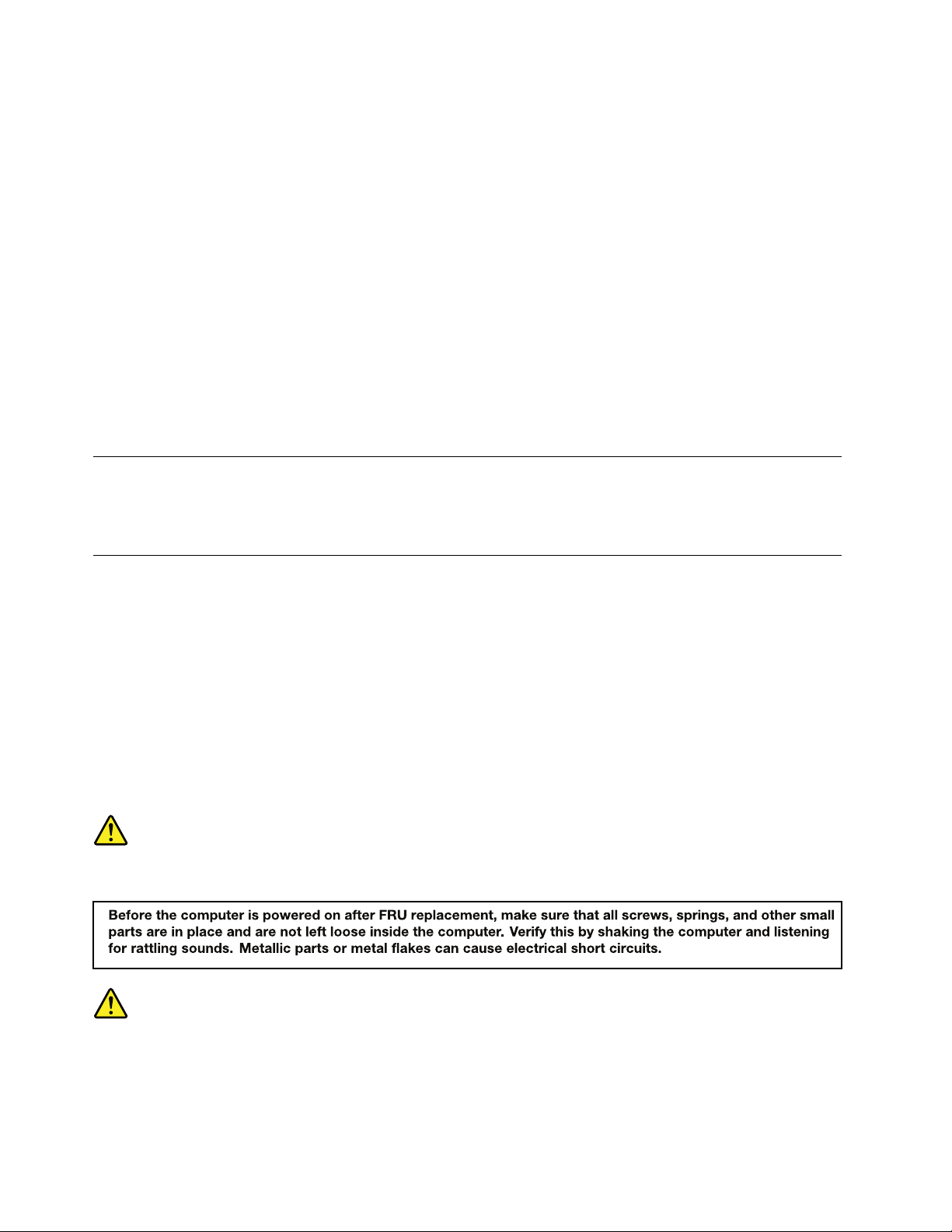
Attention:AfterreplacingaFRU,donotturnonthecomputeruntilyouhaveensuredthatallscrews,springs,
andothersmallpartsareinplaceandnonearelooseinsidethecomputer.Verifythisbyshakingthecomputer
gentlyandlisteningforrattlingsounds.Metallicpartsormetalakescancauseelectricalshortcircuits.
Attention:ThesystemboardissensitivetoandcanbedamagedbyESD.Beforetouchingit,establish
personalgroundingbytouchingagroundpointwithonehandorbyusinganESDstrap(P/N6405959).
©CopyrightLenovo2013
41
Page 48

1010Batterypack
2
1
2
Removalstepsofthebatterypack
DANGER
Useonlythebatteryspeciedinthepartslistforyourcomputer.Anyotherbatterycouldignite
orexplode.
Unlockthebatterylock1.Holdthebatterylatchintheunlockedposition,andthenremovethebattery
pack2.
Wheninstalling:Installthebatterypackintheslot.Ensurethatthebatterylatchandthebatterylockare
inthelockedpositions.
1020Bottomslotcover
Foraccess,removethisFRU:
•“1010Batterypack”onpage42
42HardwareMaintenanceManual
Page 49

Removalstepsofthebottomslotcover
2
1
Removethescrew1,andthenremovethebottomslotcover2.
StepScrew(quantity)Color
1
M2×3mm,at-head,nylon-coated(1)
1030Memorymodules
Foraccess,removetheseFRUsinorder:
•“1010Batterypack”onpage42
•“1020Bottomslotcover”onpage42
Torque
Black0.181Nm
(1.85kgf-cm)
Chapter8.RemovingorreplacingaFRU43
Page 50

Removalstepsofthememorymodules
2
1
1
a b
Releasethetwolatchesonbothedgesofthesocketatthesametime1,andthencarefullyremovethe
memorymodule2.
Wheninstalling:Insertthenotchedendofthememorymoduleintothememoryslotatanangleofabout20
degrees.Pressthememorymodulermly,andpivotitdownwarduntilitsnapsintoplace.Ensurethatthe
memorymoduleisrmlyinstalledintheslotanddoesnotmoveeasily.
Note:Ifonlyonememorymoduleistobeinstalledintothecomputeryouareservicing,thememorymodule
mustbeinstalledinSLOT -0(slot
a),butnotinSLOT -1(slotb).
44HardwareMaintenanceManual
Page 51

1040Harddiskdriveassembly
2
1
1
Foraccess,removetheseFRUsinorder:
•“1010Batterypack”onpage42
•“1020Bottomslotcover”onpage42
Importantnoticeforreplacingaharddiskdrive
Alwaystrytorunalow-levelformatbeforereplacingaharddiskdrive.Thiswillcauseallcustomerdataonthe
harddiskdrivetobelost.Ensurethatthecustomerhasacurrentbackupofthedatabeforedoingthistask.
Attention:
•Donotdropthedriveorapplyanyphysicalshocktoit.Thedriveissensitivetophysicalshock.Improper
handlingcancausedamageandpermanentlossofdata.
•Beforeremovingthedrive,havetheusermakeabackupcopyofalltheinformationonitifpossible.
•Neverremovethedrivewhilethecomputerisoperatingorinsuspendmode.
•Thedrivestartupsequenceinthecomputeryouareservicingmighthavebeenchanged.Beextremely
carefulduringwriteoperationssuchascopying,saving,orformatting.Ifyouselectanincorrectdrive,
dataorprogramscanbeoverwritten.
Removalstepsoftheharddiskdriveassembly
Removethescrews1,andthenpullthetab2.
StepScrew(quantity)Color
1
M2×3mm,at-head,nylon-coated(2)
Torque
Black0.181Nm
(1.85kgf-cm)
Chapter8.RemovingorreplacingaFRU45
Page 52

Removetheharddiskdriveassembly.
3
1
1
1
1
2
Wheninstalling:Ensurethattheharddiskdriveconnectorisattachedrmly.
Removalstepsoftheharddiskdrivebracket
Removethescrews1.
StepScrew(quantity)Color
1
M3×2.8mm,at-head,nylon-coated(4)
Black0.392Nm
Torque
(4.0kgf-cm)
Removetheharddiskdrivebracket.
1050PCIExpressMiniCardforwirelessLAN
Foraccess,removetheseFRUsinorder:
•“1010Batterypack”onpage42
•“1020Bottomslotcover”onpage42
46HardwareMaintenanceManual
Page 53

RemovalstepsofthePCIExpressMiniCardforwirelessLAN
1
1
2
3
Insteps1,unplugtheconnectorsbyusingtheremovaltoolfortheantennaRFconnectororpickupthe
connectorswithyourngersandgentlyunplugthem.Thenremovethescrew2.
StepScrew(quantity)Color
2
M2×3mm,at-head,nylon-coated(1)
Black0.181Nm
Torque
(1.85kgf-cm)
RemovethePCIExpressMiniCardforwirelessLAN.
Wheninstalling:Plugtheblackcableintothemainconnector,andthewhitecableintotheauxiliary
connector.
1060mSAT Asolid-statedrive
Foraccess,removetheseFRUsinorder:
•“1010Batterypack”onpage42
•“1020Bottomslotcover”onpage42
Chapter8.RemovingorreplacingaFRU47
Page 54

Attention:
1
1
2
•Donotdropthedriveorapplyanyphysicalshocktoit.Thedriveissensitivetophysicalshock.Improper
handlingcancausedamageandpermanentlossofdata.
•Beforeremovingthedrive,havetheusermakeabackupcopyofalltheinformationonitifpossible.
•Neverremovethedrivewhilethecomputerisoperatingorinsuspendmode.
RemovalstepsofthemSAT Asolid-statedrive
Removethescrews1.
StepScrew(quantity)Color
1
M2×3mm,at-head,nylon-coated(2)
RemovethemSATAsolid-statedrive.
1070Backupbattery
Foraccess,removetheseFRUsinorder:
•“1010Batterypack”onpage42
•“1020Bottomslotcover”onpage42
Torque
Black0.181Nm
(1.85kgf-cm)
48HardwareMaintenanceManual
Page 55

Removalstepsofthebackupbattery
1
1
1
DANGER
Useonlythebatteryspeciedinthepartslistforyourcomputer.Anyotherbatterycouldignite
orexplode.
Carefullyprythebackupbatteryoutusingascrewdriver.
1080Keyboard
Foraccess,removetheseFRUsinorder:
•“1010Batterypack”onpage42
•“1020Bottomslotcover”onpage42
Removalstepsofthekeyboard
Removethescrews1.
Wheninstalling:Ensurethatthescrewsarermlyinstalledandthekeyboardissecured.
StepScrew(quantity)Color
1
M2×6mm,at-head,nylon-coated(3)
Torque
Black0.181Nm
(1.85kgf-cm)
Chapter8.RemovingorreplacingaFRU49
Page 56

Pushhardtounlatchthekeyboard.
2
2
3
Carefullydetachthekeyboardandthenliftitupuntilyoucanseehowitisconnected.
50HardwareMaintenanceManual
Page 57

Detachthekeyboardconnector,andthenremovethekeyboard.
4
5
6
Wheninstalling:Ensurethatthekeyboardconnectorisattachedrmly.
1090Keyboardbezel
Foraccess,removetheseFRUsinorder:
•“1010Batterypack”onpage42
•“1020Bottomslotcover”onpage42
•“1080Keyboard”onpage49
Chapter8.RemovingorreplacingaFRU51
Page 58

Removalstepsofthekeyboardbezel
1
1
1
1
1
2
2
2
1
1
1
1
1
Removethescrews1and2.
StepScrew(quantity)Color
1
2
M2×6mm,at-head,nylon-coated(10)
M2×2.5mm,at-head,nylon-coated(3)
Torque
Black0.181Nm
(1.85kgf-cm)
Black0.181Nm
(1.85kgf-cm)
52HardwareMaintenanceManual
Page 59

Removethescrews3,andthendetachtheconnectors.
7
6
8
9
4
5
3
3
StepScrew(quantity)Color
3
M2×6mm,at-head,nylon-coated(2)
Wheninstalling:Ensurethatalltheconnectorsareattachedrmly.
Torque
Black0.181Nm
(1.85kgf-cm)
Chapter8.RemovingorreplacingaFRU53
Page 60

Detachthekeyboardbezelfromtheframe,andthenremovethekeyboardbezel.
10
10
10
11
10
10
10
10
10
10
2
1
1
1110Fingerprintboardbracketandngerprintboardwithcable
Foraccess,removetheseFRUsinorder:
•“1010Batterypack”onpage42
•“1020Bottomslotcover”onpage42
•“1040Harddiskdriveassembly”onpage45
•“1080Keyboard”onpage49
•“1090Keyboardbezel”onpage51
Removalstepsofthengerprintboardbracketandthengerprintboardwithcable
Removethescrews1,andthenremovethengerprintboardbracket2.
StepScrew(quantity)Color
1
M2×3mm,at-head,nylon-coated(2)
Black0.181Nm
Torque
(1.85kgf-cm)
54HardwareMaintenanceManual
Page 61

Removethengerprintboardwiththengerprintboardcable.
3
2
1
1120Powerboard
Foraccess,removetheseFRUsinorder:
•“1010Batterypack”onpage42
•“1020Bottomslotcover”onpage42
•“1040Harddiskdriveassembly”onpage45
•“1080Keyboard”onpage49
•“1090Keyboardbezel”onpage51
Removalstepsofthepowerboard
Removethescrew1,andthenremovethepowerboard.
StepScrew(quantity)Color
1
M2×3mm,at-head,nylon-coated(1)
Black0.181Nm
Torque
(1.85kgf-cm)
1130Mediacardreaderslotboard
Foraccess,removetheseFRUsinorder:
•“1010Batterypack”onpage42
•“1020Bottomslotcover”onpage42
•“1040Harddiskdriveassembly”onpage45
•“1080Keyboard”onpage49
•“1090Keyboardbezel”onpage51
•“1140Systemboardassembly”onpage57
Chapter8.RemovingorreplacingaFRU55
Page 62

Removalstepsofthemediacardreaderslotboard
1
3
2
Detachthecables.
Wheninstalling:Ensurethatthecablesareattachedrmly.
56HardwareMaintenanceManual
Page 63

Removethescrews4,andthenremovethemediacardreaderslotboard.
4
4
4
5
StepScrew(quantity)Color
4
M2×3mm,at-head,nylon-coated(3)
Black0.181Nm
Torque
(1.85kgf-cm)
1140Systemboardassembly
Foraccess,removetheseFRUsinorder:
•“1010Batterypack”onpage42
•“1020Bottomslotcover”onpage42
•“1030Memorymodules”onpage43
•“1040Harddiskdriveassembly”onpage45
•“1050PCIExpressMiniCardforwirelessLAN”onpage46
•“1060mSATAsolid-statedrive”onpage47
•“1070Backupbattery”onpage48
•“1080Keyboard”onpage49
•“1090Keyboardbezel”onpage51
Importantnoticeforreplacingthesystemboard
Whenreplacingthesystemboard,observethefollowingguidelines:
•Donotdropasystemboardonabenchtopthathasahardsurface,suchasmetal,wood,orcomposite.
•Donotapplyanyexcessiveforcetoasystemboard.
•Avoidroughhandlingofanykind.
•AvoidbendingasystemboardorhardpushingtopreventcrackingateachBallGridArray(BGA)chipset.
•Whenyouputasystemboarddown,besuretoputitonlyonapaddedsurfacesuchasanESDmat
oracorrugatedconductivesurface.
Chapter8.RemovingorreplacingaFRU57
Page 64

Locatingmajorsensitivecomponentsonthesystemboard
a
b
a
b
c
Attention:Thefollowingcomponentsmountedonasystemboardareextremelysensitive.Improper
handlingofasystemboardcancausedamagetothefollowingcomponents,andmightcauseasystem
malfunction.Whenyouservicethesystemboard,avoidanykindofroughhandling.
aGraphicschip(fordiscretegraphicsmodels)
bMicroprocessor
cPlatformControllerHub(PCH)
Formodelswithanintegratedthermalmoduleassembly
Formodelswithadiscretethermalmoduleassembly
58HardwareMaintenanceManual
Page 65

Removalstepsofthesystemboardassembly
5
4
6
3
1
2
7
7
7
Detachtheconnectors.
Wheninstalling:Ensurethatalltheconnectorsareattachedrmly.
Removethescrews
7.
StepScrew(quantity)Color
7
M2×3mm,at-head,nylon-coated(3)
Black0.181Nm
Chapter8.RemovingorreplacingaFRU59
Torque
(1.85kgf-cm)
Page 66

Liftthesystemboardassemblycarefully,andthendetachtheconnector9.
8
9
Wheninstalling:Ensurethattheconnectorisattachedrmlytothesystemboard.
1150Thermalmoduleassembly
Foraccess,removetheseFRUsinorder:
•“1010Batterypack”onpage42
•“1020Bottomslotcover”onpage42
•“1040Harddiskdriveassembly”onpage45
•“1080Keyboard”onpage49
•“1090Keyboardbezel”onpage51
•“1140Systemboardassembly”onpage57
60HardwareMaintenanceManual
Page 67

Removalstepsofthethermalmoduleassembly
1
3
5
4
2
7
6
8
Detachtheconnector1.Loosenthescrews2to7.
Wheninstalling:Ensurethattheconnectorisattachedrmlytothesystemboard.
Carefullyremovethethermalmoduleassembly.
Note:Becarefulnottodamagetheconnector.
Wheninstalling:Beforeyouattachthethermalmoduleassemblytothesystemboard,applythermal
grease,atanamountof0.2grams,onthepartmarked
aandbasshowninthefollowingillustrations.
Eithertoomuchortoolessapplicationofgreasecancauseathermalproblemduetoimperfectcontact
withacomponent.
Chapter8.RemovingorreplacingaFRU61
Page 68

Formodelswithanintegratedthermalmoduleassembly
a
a
b
Formodelswithadiscretethermalmoduleassembly
1160Speakers,LCDunitandbasecover
Foraccess,removetheseFRUsinorder:
•“1010Batterypack”onpage42
•“1020Bottomslotcover”onpage42
•“1080Keyboard”onpage49
•“1090Keyboardbezel”onpage51
62HardwareMaintenanceManual
Page 69

Removalstepsofthespeakers
1
1
1
1
1
2
Removethescrews1,andthenremovethespeakers.
StepScrew(quantity)Color
1
M2×3.1mm,at-head,nylon-coated(5)
Torque
Black0.181Nm
(1.85kgf-cm)
Chapter8.RemovingorreplacingaFRU63
Page 70

RemovalstepsoftheLCDunitandthebasecover
1
1
1
1
1
1
Releasetheantennacablesfromthecableguides.Removethescrews1.
StepScrew(quantity)Color
1
M2.5×5mm,at-head,nylon-coated(6)
Black0.392Nm
Torque
(4.0kgf-cm)
Cablerouting:Routetheantennacablesalongthecableguidesandsecuretheantennaboardswithtapes.
Attention:Whenyouroutethecables,ensurethattheyarenotsubjecttoanytension.T ensioncould
damagethecablesandwires.
64HardwareMaintenanceManual
Page 71

RemovetheLCDunitfromthebasecover.
2
2
Applyinglabelstothebasecover
Thenewbasecoverisshippedwithakitcontaininglabelsofseveralkinds.Applythelabelsasshowninthe
followingillustrationwhenyoureplacethebasecover.Forthelabelsnotshippedwiththenewbasecover,
peelthemofffromtheoldbasecover,andadherethemtothenewone.
Note:IfyoureplaceapartwiththeWindowsCerticateofAuthentication(COA)label4,returntheoldpart
withthelabelattachedtothecustomer.Otherwise,youcanprovidethecustomerwithaletter,statingthe
originallocationofthelabelonthecomputerandtheinformationonthelabel,suchasthepartnumber,
serialnumber,andproductkey.
Thefollowingillustrationshowsthelabellocationsonthebasecover.
Chapter8.RemovingorreplacingaFRU65
Page 72

1
2
3
45
1Barcodelabel
2
1
2Ratinglabel
3Systembarcodelabel
4COAlabel
5GenuineMicrosoftlabel
1170DC-inconnector
Foraccess,removetheseFRUsinorder:
•“1010Batterypack”onpage42
•“1020Bottomslotcover”onpage42
•“1040Harddiskdriveassembly”onpage45
•“1080Keyboard”onpage49
•“1090Keyboardbezel”onpage51
•“1140Systemboardassembly”onpage57
•“1160Speakers,LCDunitandbasecover”onpage62
RemovalstepsoftheDC-inconnector
RemovetheDC-inconnectorbracket,andthenremovetheDC-inconnector.
66HardwareMaintenanceManual
Page 73

2010LCDfrontbezel
1
1
2
2
2
2
Foraccess,removetheseFRUsinorder:
•“1010Batterypack”onpage42
•“1160Speakers,LCDunitandbasecover”onpage62
RemovalstepsoftheLCDfrontbezel
Removethescrews1.
StepScrew(quantity)Color
1
M2×4mm,at-head,nylon-coated(2)
Black0.181Nm
Torque
(1.85kgf-cm)
RemovetheLCDfrontbezel.
Wheninstalling:Ensurethatallthelatchesareattachedrmly.Thensecurethebezelwiththescrews.
2020Cameraandmicrophoneboard
Foraccess,removetheseFRUsinorder:
Chapter8.RemovingorreplacingaFRU67
Page 74

•“1010Batterypack”onpage42
1
2
•“1160Speakers,LCDunitandbasecover”onpage62
•“2010LCDfrontbezel”onpage67
Removalstepsofthecameraandmicrophoneboard
Detachtheconnector1andthenpeeloffthecameraandmicrophoneboard2.
Note:ThecameraandmicrophoneboardisadheredtothetopcenteroftheLCDcover.
Wheninstalling:AdherethecameraandmicrophoneboardtothetopcenteroftheLCDcoverandadjust
theplacementtoensurethattheconnectorisattachedrmly.
2030LCDpanel,LCDcable,andhinges
Foraccess,removetheseFRUsinorder:
•“1010Batterypack”onpage42
•“1160Speakers,LCDunitandbasecover”onpage62
•“2010LCDfrontbezel”onpage67
68HardwareMaintenanceManual
Page 75

RemovalstepsoftheLCDpanelandtheLCDcable
1
1
1
1
2
3
4
5
Removethescrews1,andthenremovetheLCDpanel2.
StepScrew(quantity)Color
1
M2×2.5mm,at-head,nylon-coated(4)
TurnovertheLCDpanel.ThendetachtheLCDcable.
Wheninstalling:Ensurethatthecableisattachedrmly.
Torque
Black0.181Nm
(1.85kgf-cm)
Chapter8.RemovingorreplacingaFRU69
Page 76

Removalstepsofthehinges
1
1
1
1
1
1
2
2
Removethescrews1.
StepScrew(quantity)Color
1
M2×3mm,at-head,nylon-coated(6)
Removethehinges.
2040AntennaassemblyandLCDrearcover
Torque
Black0.181Nm
(1.85kgf-cm)
Foraccess,removetheseFRUsinorder:
•“1010Batterypack”onpage42
•“1160Speakers,LCDunitandbasecover”onpage62
•“2010LCDfrontbezel”onpage67
•“2020Cameraandmicrophoneboard”onpage67
•“2030LCDpanel,LCDcable,andhinges”onpage68
70HardwareMaintenanceManual
Page 77

RemovalstepsoftheantennaassemblyandtheLCDrearcover
1
1
1
1
1
1
2
2
3
3
ReleasetheantennacablesfromthecableguidesoftheLCDrearcoverassemblyandfromthehinges.
Cablerouting:Routetheantennacablesalongthecableguidesandsecuretheantennaboardswithtapes.
Attention:Whenyouroutethecables,ensurethattheyarenotsubjecttoanytension.T ensioncould
damagethecablesandwires.
Removetheantennaassembly.
Chapter8.RemovingorreplacingaFRU71
Page 78

72HardwareMaintenanceManual
Page 79

AppendixA.Notices
Lenovomaynotoffertheproducts,services,orfeaturesdiscussedinthisdocumentinallcountries.Consult
yourlocalLenovorepresentativeforinformationontheproductsandservicescurrentlyavailableinyour
area.AnyreferencetoaLenovoproduct,program,orserviceisnotintendedtostateorimplythatonlythat
Lenovoproduct,program,orservicemaybeused.Anyfunctionallyequivalentproduct,program,orservice
thatdoesnotinfringeanyLenovointellectualpropertyrightmaybeusedinstead.However,itistheuser's
responsibilitytoevaluateandverifytheoperationofanyotherproduct,program,orservice.
Lenovomayhavepatentsorpendingpatentapplicationscoveringsubjectmatterdescribedinthis
document.Thefurnishingofthisdocumentdoesnotgiveyouanylicensetothesepatents.Y oucansend
licenseinquiries,inwriting,to:
Lenovo(UnitedStates),Inc.
1009ThinkPlace-BuildingOne
Morrisville,NC27560
U.S.A.
Attention:LenovoDirectorofLicensing
LENOVOPROVIDESTHISPUBLICATION“ASIS”WITHOUTWARRANTYOFANYKIND,EITHEREXPRESS
ORIMPLIED,INCLUDING,BUTNOTLIMITEDTO,THEIMPLIEDWARRANTIESOFNON-INFRINGEMENT,
MERCHANTABILITYORFITNESSFORAPARTICULARPURPOSE.Somejurisdictionsdonotallow
disclaimerofexpressorimpliedwarrantiesincertaintransactions,therefore,thisstatementmaynotapply
toyou.
Thisinformationcouldincludetechnicalinaccuraciesortypographicalerrors.Changesareperiodically
madetotheinformationherein;thesechangeswillbeincorporatedinneweditionsofthepublication.
Lenovomaymakeimprovementsand/orchangesintheproduct(s)and/ortheprogram(s)describedinthis
publicationatanytimewithoutnotice.
Theproductsdescribedinthisdocumentarenotintendedforuseinimplantationorotherlifesupport
applicationswheremalfunctionmayresultininjuryordeathtopersons.Theinformationcontainedinthis
documentdoesnotaffectorchangeLenovoproductspecicationsorwarranties.Nothinginthisdocument
shalloperateasanexpressorimpliedlicenseorindemnityundertheintellectualpropertyrightsofLenovo
orthirdparties.Allinformationcontainedinthisdocumentwasobtainedinspecicenvironmentsandis
presentedasanillustration.Theresultobtainedinotheroperatingenvironmentsmayvary.
Lenovomayuseordistributeanyoftheinformationyousupplyinanywayitbelievesappropriatewithout
incurringanyobligationtoyou.
Anyreferencesinthispublicationtonon-LenovoWebsitesareprovidedforconvenienceonlyanddonotin
anymannerserveasanendorsementofthoseWebsites.ThematerialsatthoseWebsitesarenotpartof
thematerialsforthisLenovoproduct,anduseofthoseWebsitesisatyourownrisk.
Anyperformancedatacontainedhereinwasdeterminedinacontrolledenvironment.Therefore,theresult
obtainedinotheroperatingenvironmentsmayvarysignicantly.Somemeasurementsmayhavebeen
madeondevelopment-levelsystemsandthereisnoguaranteethatthesemeasurementswillbethesame
ongenerallyavailablesystems.Furthermore,somemeasurementsmayhavebeenestimatedthrough
extrapolation.Actualresultsmayvary.Usersofthisdocumentshouldverifytheapplicabledatafortheir
specicenvironment.
©CopyrightLenovo2013
73
Page 80

Trademarks
ThefollowingtermsaretrademarksofLenovointheUnitedStates,othercountriesorboth:
ActiveProtectionSystem
Lenovo
Lenovologo
OneKey
MicrosoftandWindowsaretrademarksoftheMicrosoftgroupofcompanies.
Othercompany,product,orservicenamesmaybetrademarksorservicemarksofothers.
74HardwareMaintenanceManual
Page 81

Page 82

PartNumber:
PrintedinChina
(1P)P/N:
*1P*
 Loading...