

Lenovo K100 Hardware Replacement Manual
Hardware Replacement Guide
31031416 Greenland HRG_EN.indd 29 2007.8.20 4:06:04 PM

31031416 Greenland HRG_EN.indd 30 2007.8.20 4:06:04 PM
Contents
Overview ................................................................................................ 1
Chapter 1 Locations ......................................................................... 3
Locating components .......................................................................... 3
Locating connectors on the front of the computer ................................ 4
Locating connectors on the rear of the computer ................................. 5
Identifying parts on the system board ................................................... 8
Chapter 2 Replacing hardware ...................................................... 10
Removing the computer cover ........................................................... 10
Removing and replacing the front bezel ............................................... 11
Replacing the power supply ............................................................... 12
Replacing the heat sink assembly ...................................................... 13
Replacing a memory module .............................................................. 15
Replacing an adapter ......................................................................... 16
Replacing the hard disk drive ............................................................. 18
Replacing an optical drive .................................................................. 20
Replacing the system fan assembly ................................................... 21
Replacing the keyboard ..................................................................... 22
Replacing the mouse ......................................................................... 23
Replacing the External speaker .......................................................... 24
Completing the installation ................................................................. 24
Appendix. ........................................................................................... 26
31031416 Greenland HRG_EN.indd 31 2007.8.20 4:06:05 PM

31031416 Greenland HRG_EN.indd 32 2007.8.20 4:06:05 PM

1
Hardware Replacement Guide
Overview
This guide is intended to be used by customers who are replacing Customer Replaceable Units (CRUs) as well
as trained service personnel who are replacing Field Replaceable Units (FRUs). In this guide, CRUs and FRUs
will often be referred to as parts.
Note
Trained service personnel should refer to the Hardware Maintenance Manual (HMM) for parts ordering
information.
This guide does not include procedures for all parts. It is expected that cables, switches, and certain
mechanical parts can be replaced by trained service personnel without the need for step-by-step procedures.
Note
Use only parts provided by Lenovo™.
The description of the TV card in this manual is only used for the machines which have the TV card. It is invalid
for those machines which do not have TV card.
This guide contains procedures for replacing the following parts:
• Power supply
• Memory modules
• Adapter
• Hard disk drive
• Optical drive
• System fan assembly
• Keyboard
• Mouse
• External Speakers
Safety information for replacing CRUs
Do not open your computer or attempt any repair before reading the “Important safety information” in the Safety
and Warranty Guide that was included with your computer. If you no longer have this copy of the Safety and
Warranty Guide, you can obtain one online from the Support Web site at http://www.lenovo.com/support.
Additional information resources
If you have Internet access, the most up-to-date information for your computer is available from the World Wide
Web.
31031416 Greenland HRG_EN.indd 1 2007.8.20 4:05:34 PM

2
Hardware Replacement Guide
You can find the following information:
• CRU removal and installation information
• Publications
• Troubleshooting information
• Parts information
• Links to other useful sources of information
To access this information, go to http://www.lenovo.com/support.
Tools required
To replace some parts in your computer, you will need a flat-blade or Phillips screwdriver. Additional tools might
be needed for certain parts.
Handling static-sensitive devices
Static electricity, although harmless to you, can seriously damage computer components.
When you are replacing a part, do not open the static-protective package containing the new part until the
defective part has been removed from the computer and you are ready to install the new part.
When you handle parts and other computer components, take these precautions to avoid static-electricity
damage:
• Limit your movement. Movement can cause static-electricity to build up around you.
• Always handle parts and other computer components carefully. Handle adapters, memory modules, system
boards, and microprocessors by the edges. Never touch any exposed circuitry.
• Prevent others from touching the parts and other computer components.
• Before you replace a new part, touch the static-protective package containing the part to a metal expansion-
slot cover or other unpainted metal surface on the computer for at least two seconds. This reduces static
electricity in the package and your body.
• When possible, remove the new part from the static-protective packaging, and install it directly in the
computer without setting the part down. When this is not possible, place the static-protective package that
the part came in on a smooth, level surface and place the part on it.
• Do not place the part on the computer cover or other metal surface.
31031416 Greenland HRG_EN.indd 2 2007.8.20 4:05:35 PM
3
Hardware Replacement Guide
Locations
Chapter
This chapter provides illustrations to help locate the various connectors, controls and components of the
computer. To remove the computer cover, refer to “Removing the computer cover”.
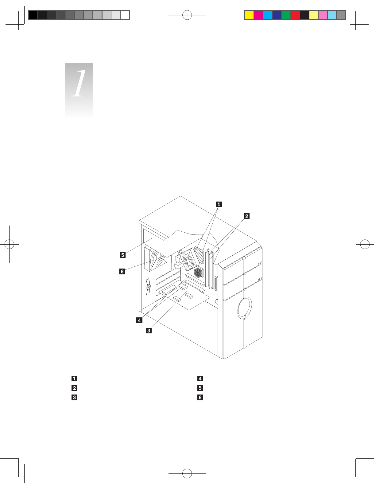
Locating components
The following illustration will help you locate the various components in your computer.
Microprocessor fan and heat sink PCIe adapter connectors
Memory modules Power supply
PCIe adapter card System fan
31031416 Greenland HRG_EN.indd 3 2007.8.20 4:05:37 PM

4
Hardware Replacement Guide
Locating connectors on the front of the computer
The following illustration shows the location of connectors on the front of the computer.
F-1
F-2
F-1 Power switch on the top
[1-1] [1-2]
[1-1] Reset [1-2] Power Switch
31031416 Greenland HRG_EN.indd 4 2007.8.20 4:05:37 PM
5
Hardware Replacement Guide
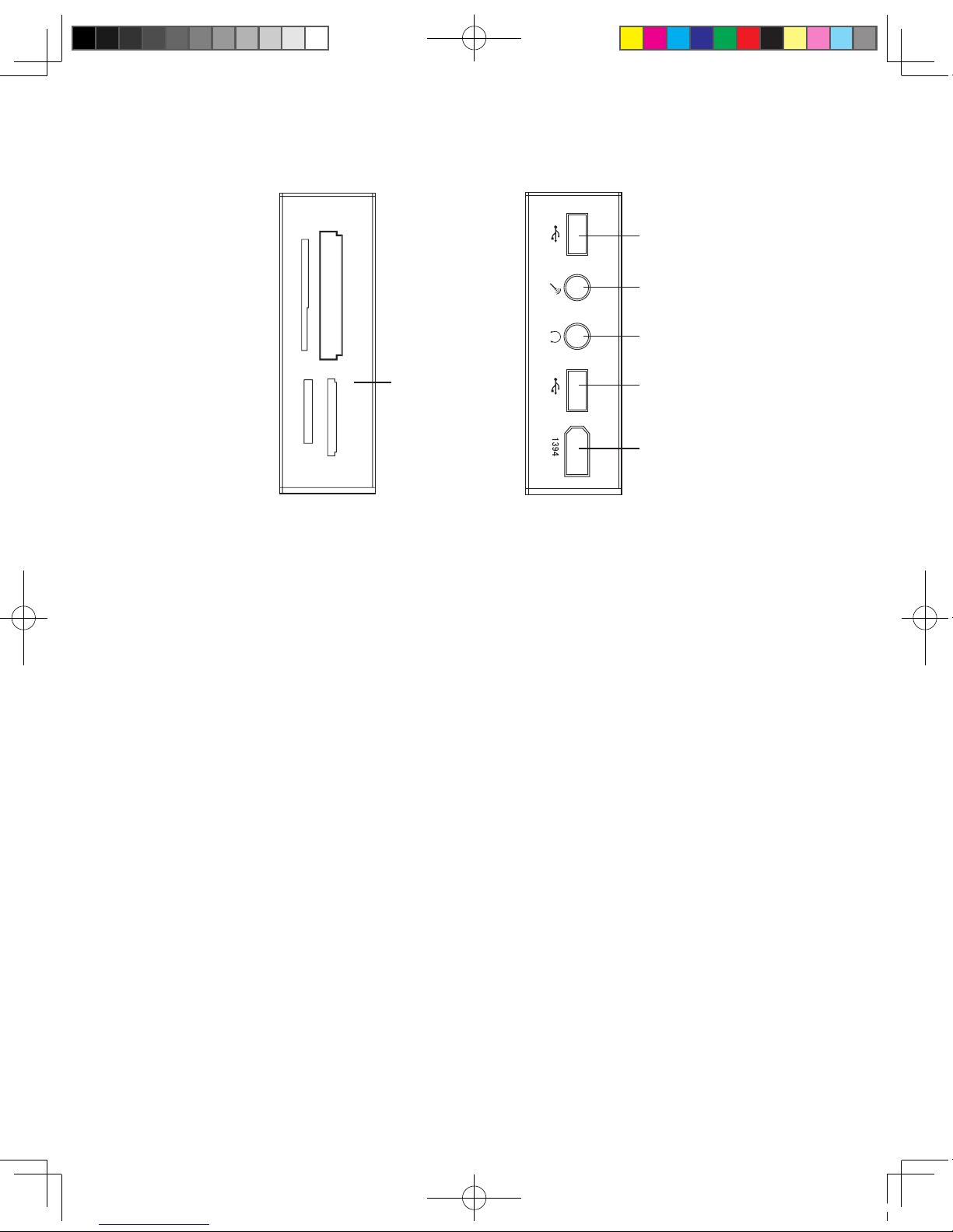
F-2 Digital connector (open the Digital Panel)
MS/MS Pro
CF/MD
SM
SD/MMC
[D-1]
[D-3]
[D-2]
[D-2]
[D-4]
[D-5]
[D-1] Card Reader [D-4] Headphone connector
[D-2] USB connector [D-5] Microphone connector
[D-3] 1394 connector (Only some models a re
equipped with this connector. )
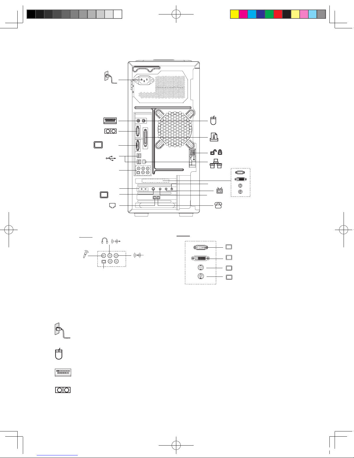
Locating connectors on the rear of the computer
The following illustration shows the location of connectors on the rear of the computer.
The following illustrations show connections located at the rear of some computer models. The locations of
connectors on your computer will be similar to, but possibly not identical to these. Following the illustrations is a
key that explains the symbol callouts used in the figures.
31031416 Greenland HRG_EN.indd 5 2007.8.20 4:05:38 PM
6
Hardware Replacement Guide
VGA-1
SPDIF
A-2
A-2
V-2
V-2
S-2
DVI
X-2
S-1
S-3
FM
ANT IN
L&R
V-2
————The external VGA Card may have some of these connectors, but not have all of them. Use the
correct connector according to the monitor you used.
Key to symbols used in the above illustrations of the rear of the chassis:
——— Power Connector: To supply power to the computer
—————PS/2 Mouse Connector: To connect a mouse having a PS/2 connector
———PS/2 Keyboard Connector: To connect a keyboard having a PS/2 connector
———Serial Connector: To connect devices requiring a serial connection (COM Connector)
31031416 Greenland HRG_EN.indd 6 2007.8.20 4:05:39 PM
 Loading...