

Page 1

HardwareMaintenanceManual
Lenovo3000JSeries
Types7387,7388,7389,7390,7391,7392,7393,7394,7395,7396,
7397,7398
Page 2

Page 3

HardwareMaintenanceManual
Lenovo3000JSeries
Types7387,7388,7389,7390,7391,7392,7393,7394,7395,7396,
7397,7398
Page 4

Note:Beforeusingthisinformationandtheproductitsupports,besuretoreadtheinformationunderAppendixA
“Notices”onpage189.
TenthEdition(September2010)
©CopyrightLenovo2006,2010.
LENOVOproducts,data,computersoftware,andserviceshavebeendevelopedexclusivelyatprivateexpenseandare
soldtogovernmentalentitiesascommercialitemsasdenedby48C.F .R.2.101withlimitedandrestrictedrightsto
use,reproductionanddisclosure.
LIMITEDANDRESTRICTEDRIGHTSNOTICE:Ifproducts,data,computersoftware,orservicesaredeliveredpursuant
aGeneralServicesAdministration“GSA”contract,use,reproduction,ordisclosureissubjecttorestrictionssetforth
inContractNo.GS-35F-05925.
Page 5

Contents
Chapter1.Aboutthismanual.....1
ImportantSafetyInformation..........1
ImportantinformationaboutreplacingRoHS
compliantFRUs...............1
Chapter2.Safetyinformation.....3
Generalsafety................3
Electricalsafety...............3
Safetyinspectionguide............5
Handlingelectrostaticdischarge-sensitive
devices..................5
Groundingrequirements............6
Safetynotices(multi-lingualtranslations).....6
Chapter3.Generalinformation....29
TheLenovoCareprogram..........29
Additionalinformationresources.......29
Specications...............29
Machinetypes7387,7388,7389,7393,7394,
and7395...............30
Machinetypes7390,7391,7392,7396,7397,
and7398...............30
Chapter4.GeneralCheckout.....33
Problemdeterminationtips..........33
Chapter5.Diagnostics........35
PC-DoctorforWindows...........35
PC-DoctorforDOS.............35
CreatingadiagnosticCDimage......35
Creatingdiagnosticdiskettes.......36
RunningdiagnosticsfromtheCDor
diskettes...............36
RunningdiagnosticsfromtheRescueand
Recoveryworkspace..........36
PC-DoctorforWindowsPE..........37
RunningdiagnosticsfromtheRescueand
Recoveryworkspace..........37
Navigatingthroughthediagnosticsprograms..37
Runningtests...............37
Testresults..............38
Fixeddiskadvancedtest(FDAT)......38
QuickandFullerase-harddrive......40
Viewingthetestlog.............40
Chapter6.UsingtheSetupUtility..41
StartingtheSetupUtilityprogram.......41
Viewingandchangingsettings........41
Usingpasswords..............41
UserPassword.............41
AdministratororSupervisorPassword...42
Selectingastartupdevice..........42
Selectingatemporarystartupdevice....42
Changingthestartupdevicesequence...43
ExitingfromtheSetupUtilityprogram.....43
Chapter7.Symptom-to-FRUIndex.45
Harddiskdrivebooterror..........45
PowerSupplyProblems...........45
Diagnosticerrorcodes...........46
Beepsymptoms..............63
POSTerrorcodes.............64
Miscellaneouserrormessages........65
Undeterminedproblems...........67
Chapter8.ReplacingFRUs(Types
7387,7388,7389,7393,7394,and
7395)..................69
Rearconnectors..............69
Removingthecovers............70
Locations.................70
Identifyingpartsonthesystemboard......71
MachineTypes7387,7388,and7389....72
MachineTypes7393,7394,and7395....73
Removingandreplacingthefrontbezel.....73
Replacingamemorymodule.........74
ReplacingaPCIadapter...........75
ReplacingtheCMOSbattery.........76
Replacingthepowersupply.........76
Replacingthesystemboard(Types7393,7394,
and7395)................77
Replacingthesystemboard(Types7387,7388,
and7389)................80
Replacingthemicroprocessor(Types7393,7394,
and7395)................82
Replacingthemicroprocessor(Types7387,7388,
and7389)................85
Replacingtheprimaryharddiskdrive......88
Replacinganopticaldrive..........89
Replacingthediskettedrive.........90
Replacingthepowerswitch/LEDassembly...91
Replacingthefrontpanelcardassembly....91
CompletingtheFRUreplacement.......92
Chapter9.ReplacingFRUs(Types
7390,7391,7392,7396,7397,and
7398)..................93
©CopyrightLenovo2006,2010
v
Page 6

Rearconnectors..............93
Removingthecover............94
Locations.................94
Identifyingpartsonthesystemboard......95
MachineTypes7390,7391,and7392....96
MachineTypes7396,7397,and7398....97
Removingandreplacingthedrivebayassembly.97
Replacingamemorymodule.........98
ReplacingaPCIadapter...........99
ReplacingtheCMOSbattery.........100
Replacingthepowersupply.........101
Replacingthesystemboard(Types7396,7397,
and7398)................102
Replacingthesystemboard(Types7390,7391,
and7392)................105
Replacingthemicroprocessor(Types7396,7397,
and7398)................108
Replacingthemicroprocessor(Types7390,7391,
and7392)................111
Replacingtheharddiskdrive.........114
Replacinganopticaldrive..........115
Replacingthediskettedrive.........116
Replacingthepowerswitch/LEDassembly...116
Replacingthefrontpanelcard........117
CompletingtheFRUreplacement.......117
Chapter10.FRUlists........119
MachineType7387.............119
MachineType7388.............127
MachineType7389.............132
MachineType7390.............136
MachineType7392.............140
MachineType7393.............144
MachineType7394.............153
MachineType7395.............157
MachineType7396.............168
MachineType7397.............176
MachineType7398.............181
Chapter11.AdditionalService
Information.............185
Securityfeatures..............185
HardwarecontrolledPasswords......185
Operatingsystempassword.......185
Vitalproductdata............185
BIOSlevels................185
Flashupdateprocedures..........185
Updating(ashing)BIOSfromadiskette...186
RecoveringfromaPOST/BIOSupdatefailure..186
Powermanagement............186
Automaticcongurationandpowerinterface
(ACPI)BIOS..............186
AutomaticPower-Onfeatures.......186
Recoveringsoftware............187
AppendixA.Notices........189
Televisionoutputnotice...........190
Trademarks................190
Index.................191
viHardwareMaintenanceManualLenovo3000JSeries
Page 7
Chapter1.Aboutthismanual
ThismanualcontainsserviceandreferenceinformationforLenovo®computerslistedonthecover.Itis
intendedonlyfortrainedservicerswhoarefamiliarwithLenovocomputerproducts.
BeforeservicingaLenovoproduct,besuretoreadtheSafetyInformation.SeeChapter2“Safety
information”onpage3
TheSymptom-to-FRUIndexandAdditionalServiceInformationchaptersarenotspecictoanymachine
typeandareapplicabletoallLenovocomputers.
ThismanualincludesacompleteFRUpartnumberlistingforeachmachinetypeandmodellistedonthe
cover.Ifyouhaveinternetaccess,FRUpartnumbersarealsoavailableat:
http:/www.lenovo.com/support
ImportantSafetyInformation
Besuretoreadallcautionanddangerstatementsinthisbookbeforeperforminganyoftheinstructions.
VeuillezliretouteslesconsignesdetypeDANGERetATTENTIONduprésentdocumentavantd'exécuter
lesinstructions.
LesenSieunbedingtalleHinweisevomTyp"ACHTUNG"oder"VORSICHT"indieserDokumentation,bevor
SieirgendwelcheVorgängedurchführen
.
LeggereleistruzioniintrodottedaATTENZIONEePERICOLOpresentinelmanualeprimadieseguireuna
qualsiasidelleistruzioni
Certique-sedelertodasasinstruçõesdecuidadoeperigonestemanualantesdeexecutarqualquer
umadasinstruções
Esimportantequeleatodaslasdeclaracionesdeprecauciónydepeligrodeestemanualantesdeseguir
lasinstrucciones.
ImportantinformationaboutreplacingRoHScompliantFRUs
RoHS,TheRestrictionofHazardousSubstancesinElectricalandElectronicEquipmentDirective
(2002/95/EC)isaEuropeanUnionlegalrequirementaffectingtheglobalelectronicsindustry.RoHS
requirementsmustbeimplementedonLenovoproductsplacedonthemarketafterJune2006.
ProductsonthemarketbeforeJune2006arenotrequiredtohaveRoHScompliantparts.So,ifthe
partsarenotcompliantoriginally,replacementpartscanalsobenoncompliant,butinallcases,ifthe
partsarecompliant,thereplacementpartsmustalsobecompliant.
©CopyrightLenovo2006,2010
1
Page 8
LenovoplanstotransitiontoRoHScompliancewellbeforetheimplementationdateandexpectsits
supplierstobereadytosupportLenovo'srequirementsandschedule.Productssoldin2005,willcontain
someRoHScompliantFRUs.ThefollowingstatementpertainstotheseproductsandanyproductLenovo
producescontainingRoHScompliantparts.
RoHScompliantLenovopartshaveuniqueFRUpartnumbers.BeforeorafterJune,2006,failedRoHS
compliantpartsmustalwaysbereplacedusingRoHScompliantFRUs,soonlytheFRUsidentiedas
compliantinthesystemHMMordirectsubstitutionsforthoseFRUscanbeused.
ProductsmarketedbeforeJune2006ProductsmarketedafterJune2006
Currentororiginalpart
Non-RoHSCanbeNon-RoHS
Non-RoHSCanbeRoHS
Non-RoHSCansubtoRoHS
RoHSMustbeRoHS
ReplacementFRU
Currentororiginalpart
MustbeRoHSMustbeRoHS
ReplacementFRU
Note:AdirectsubstitutionisapartwithadifferentFRUpartnumberthatisautomaticallyshippedbythe
distributioncenteratthetimeoforder.
RelatedWebURLsare:
•LenovoinformationforSupplierswebsite:
http://www-03.ibm.com/procurement/proweb.nsf/ContentDocsByTitle/
United+States~Information+for+suppliers
•RoHSDirective:
http://europa.eu.int/eur-lex/pri/en/oj/dat/2003/l_037/l_03720030213en00190023.pdf
•CaliforniaSenateBills20,50:
http://www.ciwmb.ca.gov/HHW/Events/AnnualConf/2004/presentation/MPaparian.pdf
2HardwareMaintenanceManualLenovo3000JSeries
Page 9

Chapter2.Safetyinformation
Thischaptercontainsthesafetyinformationthatyouneedtobefamiliarwithbeforeservicingacomputer.
Generalsafety
Followtheserulestoensuregeneralsafety:
•Observegoodhousekeepingintheareaofthemachinesduringandaftermaintenance.
•Whenliftinganyheavyobject:
1.Ensureyoucanstandsafelywithoutslipping.
2.Distributetheweightoftheobjectequallybetweenyourfeet.
3.Useaslowliftingforce.Nevermovesuddenlyortwistwhenyouattempttolift.
4.Liftbystandingorbypushingupwithyourlegmuscles;thisactionremovesthestrainfromthe
musclesinyourback.Donotattempttoliftanyobjectsthatweighmorethan16kg(35lb)orobjects
thatyouthinkaretooheavyforyou.
•Donotperformanyactionthatcauseshazardstothecustomer,orthatmakestheequipmentunsafe.
•Beforeyoustartthemachine,ensurethatotherservicerepresentativesandthecustomer'spersonnelare
notinahazardousposition.
•Placeremovedcoversandotherpartsinasafeplace,awayfromallpersonnel,whileyouareservicing
themachine.
•Keepyourtoolcaseawayfromwalkareassothatotherpeoplewillnottripoverit.
•Donotwearlooseclothingthatcanbetrappedinthemovingpartsofamachine.Ensurethatyoursleeves
arefastenedorrolledupaboveyourelbows.Ifyourhairislong,fastenit.
•Inserttheendsofyournecktieorscarfinsideclothingorfastenitwithanonconductiveclip,approximately
8centimeters(3inches)fromtheend.
•Donotwearjewelry,chains,metal-frameeyeglasses,ormetalfastenersforyourclothing.
Remember:Metalobjectsaregoodelectricalconductors.
•Wearsafetyglasseswhenyouare:hammering,drillingsoldering,cuttingwire,attachingsprings,using
solvents,orworkinginanyotherconditionsthatmightbehazardoustoyoureyes.
•Afterservice,reinstallallsafetyshields,guards,labels,andgroundwires.Replaceanysafetydevice
thatiswornordefective.
•Reinstallallcoverscorrectlybeforereturningthemachinetothecustomer.
Electricalsafety
CAUTION:
Electricalcurrentfrompower,telephone,andcommunicationcablescanbehazardous.Toavoid
personalinjuryorequipmentdamage,disconnecttheattachedpowercords,telecommunication
systems,networks,andmodemsbeforeyouopentheserver/workstationcovers,unlessinstructed
otherwiseintheinstallationandcongurationprocedures.
Observethefollowingruleswhenworkingonelectricalequipment.
©CopyrightLenovo2006,2010
3
Page 10

Important:Useonlyapprovedtoolsandtestequipment.Somehandtoolshavehandlescoveredwithasoft
materialthatdoesnotinsulateyouwhenworkingwithliveelectricalcurrents.Manycustomershave,near
theirequipment,rubberoormatsthatcontainsmallconductiveberstodecreaseelectrostaticdischarges.
Donotusethistypeofmattoprotectyourselffromelectricalshock.
•Findtheroomemergencypower-off(EPO)switch,disconnectingswitch,orelectricaloutlet.Ifanelectrical
accidentoccurs,youcanthenoperatetheswitchorunplugthepowercordquickly.
•Donotworkaloneunderhazardousconditionsornearequipmentthathashazardousvoltages.
•Disconnectallpowerbefore:
–Performingamechanicalinspection
–Workingnearpowersupplies
–Removingorinstallingmainunits
•Beforeyoustarttoworkonthemachine,unplugthepowercord.Ifyoucannotunplugit,askthecustomer
topower-offthewallboxthatsuppliespowertothemachineandtolockthewallboxintheoffposition.
•Ifyouneedtoworkonamachinethathasexposedelectricalcircuits,observethefollowingprecautions:
–Ensurethatanotherperson,familiarwiththepower-offcontrols,isnearyou.
Remember:Anotherpersonmustbetheretoswitchoffthepower,ifnecessary.
–Useonlyonehandwhenworkingwithpowered-onelectricalequipment;keeptheotherhandinyour
pocketorbehindyourback.
Remember:Theremustbeacompletecircuittocauseelectricalshock.Byobservingtheaboverule,
youmaypreventacurrentfrompassingthroughyourbody.
–Whenusingtesters,setthecontrolscorrectlyandusetheapprovedprobeleadsandaccessoriesfor
thattester.
–Standonsuitablerubbermats(obtainedlocally,ifnecessary)toinsulateyoufromgroundssuchas
metaloorstripsandmachineframes.
Observethespecialsafetyprecautionswhenyouworkwithveryhighvoltages;theseinstructionsarein
thesafetysectionsofmaintenanceinformation.Useextremecarewhenmeasuringhighvoltages.
•Regularlyinspectandmaintainyourelectricalhandtoolsforsafeoperationalcondition.
•Donotusewornorbrokentoolsandtesters.
•Neverassumethatpowerhasbeendisconnectedfromacircuit.First,checkthatithasbeenpowered-off.
•Alwayslookcarefullyforpossiblehazardsinyourworkarea.Examplesofthesehazardsaremoistoors,
nongroundedpowerextensioncables,powersurges,andmissingsafetygrounds.
•Donottouchliveelectricalcircuitswiththereectivesurfaceofaplasticdentalmirror.Thesurfaceis
conductive;suchtouchingcancausepersonalinjuryandmachinedamage.
•Donotservicethefollowingpartswiththepoweronwhentheyareremovedfromtheirnormaloperating
placesinamachine:
–Powersupplyunits
–Pumps
–Blowersandfans
–Motorgenerators
andsimilarunits.(Thispracticeensurescorrectgroundingoftheunits.)
•Ifanelectricalaccidentoccurs:
–Usecaution;donotbecomeavictimyourself.
–Switchoffpower.
–Sendanotherpersontogetmedicalaid.
4HardwareMaintenanceManualLenovo3000JSeries
Page 11

Safetyinspectionguide
Theintentofthisinspectionguideistoassistyouinidentifyingpotentiallyunsafeconditionsonthese
products.Eachmachine,asitwasdesignedandbuilt,hadrequiredsafetyitemsinstalledtoprotectusers
andservicepersonnelfrominjury.Thisguideaddressesonlythoseitems.However,goodjudgmentshould
beusedtoidentifypotentialsafetyhazardsduetoattachmentoffeaturesoroptionsnotcoveredbythis
inspectionguide.
Ifanyunsafeconditionsarepresent,youmustdeterminehowserioustheapparenthazardcouldbeand
whetheryoucancontinuewithoutrstcorrectingtheproblem.
Considertheseconditionsandthesafetyhazardstheypresent:
•Electricalhazards,especiallyprimarypower(primaryvoltageontheframecancauseseriousorfatal
electricalshock).
•Explosivehazards,suchasadamagedCRTfaceorbulgingcapacitor
•Mechanicalhazards,suchaslooseormissinghardware
Theguideconsistsofaseriesofstepspresentedinachecklist.Beginthecheckswiththepoweroff,and
thepowercorddisconnected.
Checklist:
1.Checkexteriorcoversfordamage(loose,broken,orsharpedges).
2.Power-offthecomputer.Disconnectthepowercord.
3.Checkthepowercordfor:
a.Athird-wiregroundconnectoringoodcondition.Useametertomeasurethird-wiregroundcontinuity
for0.1ohmorlessbetweentheexternalgroundpinandframeground.
b.Thepowercordshouldbetheappropriatetypeasspeciedinthepartslistings.
c.Insulationmustnotbefrayedorworn.
4.Removethecover.
5.Checkforanyobviousalterations.Usegoodjudgmentastothesafetyofanyalterations.
6.Checkinsidetheunitforanyobviousunsafeconditions,suchasmetallings,contamination,wateror
otherliquids,orsignsofreorsmokedamage.
7.Checkforworn,frayed,orpinchedcables.
8.Checkthatthepower-supplycoverfasteners(screwsorrivets)havenotbeenremovedortamperedwith.
Handlingelectrostaticdischarge-sensitivedevices
Anycomputerpartcontainingtransistorsorintegratedcircuits(ICs)shouldbeconsideredsensitiveto
electrostaticdischarge(ESD).ESDdamagecanoccurwhenthereisadifferenceinchargebetweenobjects.
ProtectagainstESDdamagebyequalizingthechargesothatthemachine,thepart,theworkmat,andthe
personhandlingthepartareallatthesamecharge.
Notes:
1.Useproduct-specicESDprocedureswhentheyexceedtherequirementsnotedhere.
2.MakesurethattheESDprotectivedevicesyouusehavebeencertied(ISO9000)asfullyeffective.
WhenhandlingESD-sensitiveparts:
•Keepthepartsinprotectivepackagesuntiltheyareinsertedintotheproduct.
•Avoidcontactwithotherpeople.
Chapter2.Safetyinformation5
Page 12
•Wearagroundedwriststrapagainstyourskintoeliminatestaticonyourbody.
•Preventthepartfromtouchingyourclothing.Mostclothingisinsulativeandretainsachargeevenwhen
youarewearingawriststrap.
•Usetheblacksideofagroundedworkmattoprovideastatic-freeworksurface.Thematisespecially
usefulwhenhandlingESD-sensitivedevices.
•Selectagroundingsystem,suchasthoselistedbelow,toprovideprotectionthatmeetsthespecic
servicerequirement.
Note:TheuseofagroundingsystemisdesirablebutnotrequiredtoprotectagainstESDdamage.
–AttachtheESDgroundcliptoanyframeground,groundbraid,orgreen-wireground.
–UseanESDcommongroundorreferencepointwhenworkingonadouble-insulatedor
battery-operatedsystem.Youcanusecoaxorconnector-outsideshellsonthesesystems.
–Usetheroundground-prongoftheacplugonac-operatedcomputers.
Groundingrequirements
Electricalgroundingofthecomputerisrequiredforoperatorsafetyandcorrectsystemfunction.Proper
groundingoftheelectricaloutletcanbeveriedbyacertiedelectrician.
Safetynotices(multi-lingualtranslations)
Thecautionanddangersafetynoticesinthissectionareprovidedinthefollowinglanguages:
•English
•Arabic
•Brazilian/Portuguese
•Chinese(simplied)
•Chinese(traditional)
•French
•German
•Hebrew
•Italian
•Korean
•Spanish
DANGER
Electricalcurrentfrompower,telephoneandcommunicationcablesishazardous.
Toavoidashockhazard:
•Donotconnectordisconnectanycablesorperforminstallation,maintenance,orreconguration
ofthisproductduringanelectricalstorm.
•Connectallpowercordstoaproperlywiredandgroundedelectricaloutlet.
•Connecttoproperlywiredoutletsanyequipmentthatwillbeattachedtothisproduct.
6HardwareMaintenanceManualLenovo3000JSeries
Page 13
•Whenpossible,useonehandonlytoconnectordisconnectsignalcables.
•Neverturnonanyequipmentwhenthereisevidenceofre,water,orstructuraldamage.
•Disconnecttheattachedpowercords,telecommunicationssystems,networks,andmodems
beforeyouopenthedevicecovers,unlessinstructedotherwiseintheinstallationandconguration
procedures.
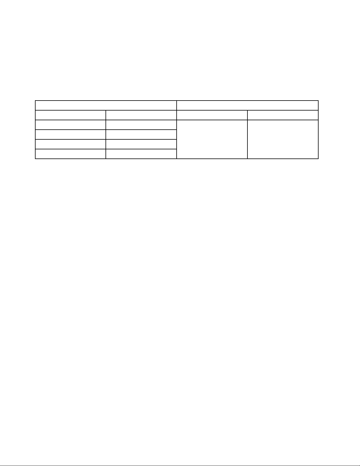
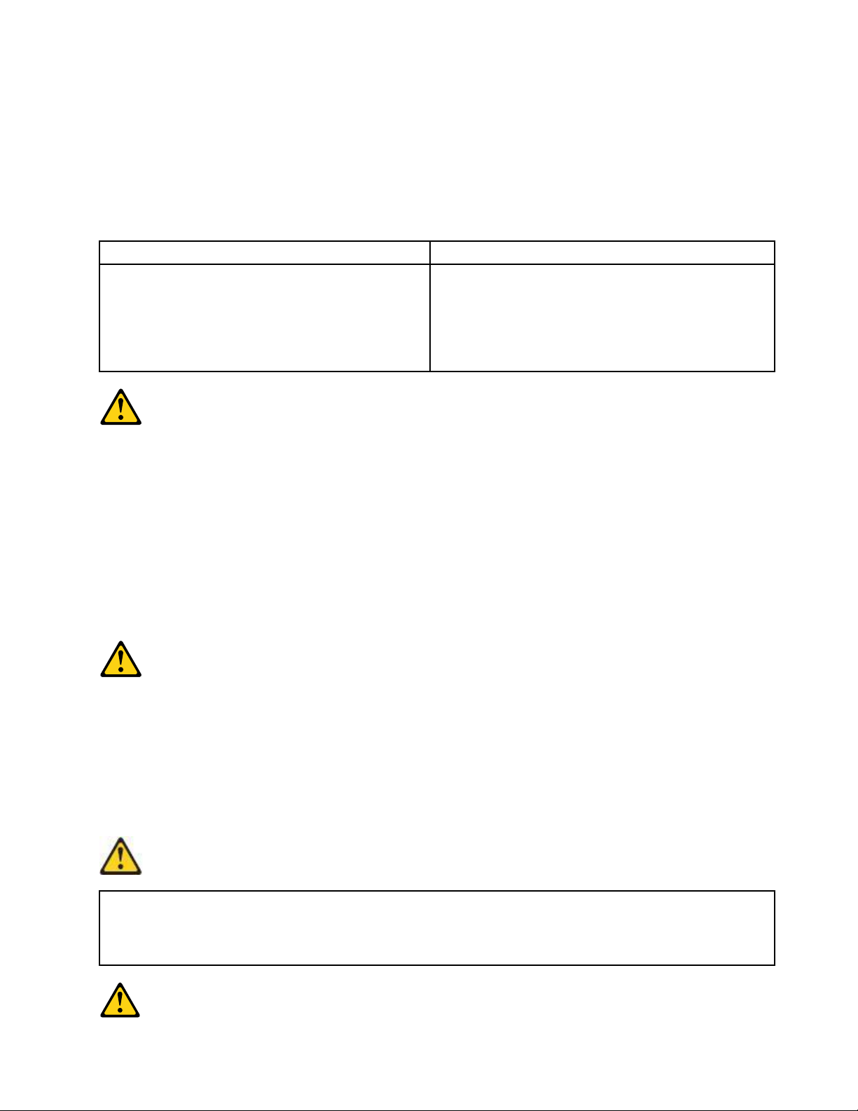
•Connectanddisconnectcablesasdescribedinthefollowingtableswheninstalling,moving,or
openingcoversonthisproductorattacheddevices.
ToConnectToDisconnect
1.TurneverythingOFF.
2.First,attachallcablestodevices.
3.Attachsignalcablestoconnectors.
4.Attachpowercordstooutlet.
5.TurndeviceON.
1.TurneverythingOFF .
2.First,removepowercordsfromoutlet.
3.Removesignalcablesfromconnectors.
4.Removeallcablesfromdevices.
CAUTION:
Whenreplacingthelithiumbattery,useonlyPartNumber45C1566oranequivalenttypebattery
recommendedbythemanufacturer.Ifyoursystemhasamodulecontainingalithiumbattery,replace
itonlywiththesamemoduletypemadebythesamemanufacturer.Thebatterycontainslithiumand
canexplodeifnotproperlyused,handled,ordisposedof.Donot:
•Throworimmerseintowater
•Heattomorethan100°C(212°F)
•Repairordisassemble
Disposeofthebatteryasrequiredbylocalordinancesorregulations.
CAUTION:
Whenlaserproducts(suchasCD-ROMs,DVD-ROMdrives,beropticdevices,ortransmitters)are
installed,notethefollowing:
•Donotremovethecovers.Removingthecoversofthelaserproductcouldresultinexposureto
hazardouslaserradiation.Therearenoserviceablepartsinsidethedevice.
•Useofcontrolsoradjustmentsorperformanceofproceduresotherthanthosespeciedherein
mightresultinhazardousradiationexposure.
DANGER
SomelaserproductscontainanembeddedClass3AorClass3Blaserdiode.Notethefollowing:
Laserradiationwhenopen.Donotstareintothebeam,donotviewdirectlywithoptical
instruments,andavoiddirectexposuretothebeam.
Chapter2.Safetyinformation7
Page 14
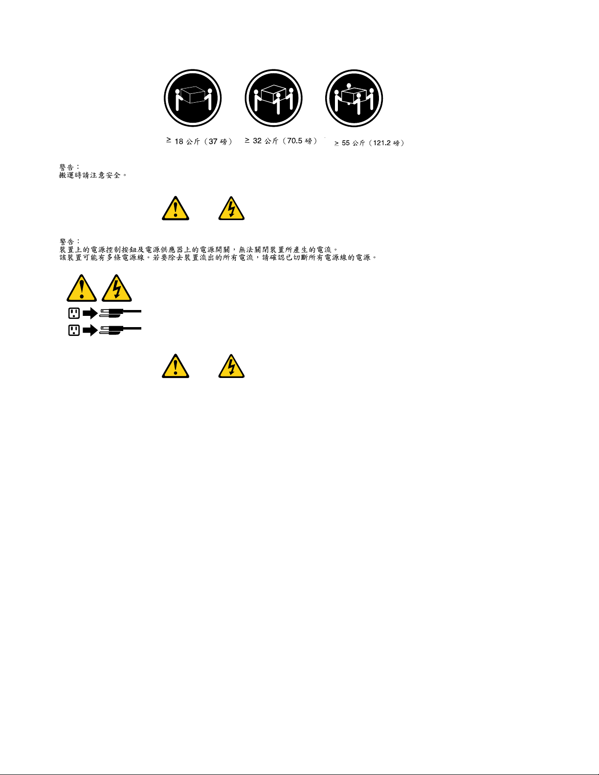
≥18kg(37lbs)≥32kg(70.5lbs)≥55kg(121.2lbs)
1
2
CAUTION:
Usesafepracticeswhenlifting.
CAUTION:
Thepowercontrolbuttononthedeviceandthepowerswitchonthepowersupplydonotturnoff
theelectricalcurrentsuppliedtothedevice.Thedevicealsomighthavemorethanonepower
cord.Toremoveallelectricalcurrentfromthedevice,ensurethatallpowercordsaredisconnected
fromthepowersource.
8HardwareMaintenanceManualLenovo3000JSeries
Page 15
Chapter2.Safetyinformation9
Page 16
≥18kg(37lbs)≥32kg(70.5lbs)≥55kg(121.2lbs)
1
2
PERIGO
10HardwareMaintenanceManualLenovo3000JSeries
Page 17
Acorrenteelétricaprovenientedecabosdealimentação,detelefoneedecomunicaçõeséperigosa.
Paraevitarriscodechoqueelétrico:
•Nãoconectenemdesconectenenhumcaboouexecuteinstalação,manutençãooureconguração
desteprodutoduranteumatempestadecomraios.
•Conectetodososcabosdealimentaçãoatomadaselétricascorretamenteinstaladaseaterradas.
•Todoequipamentoqueforconectadoaesteprodutodeveserconectadoatomadascorretamente
instaladas.
•Quandopossível,utilizeapenasumadasmãosparaconectaroudesconectarcabosdesinal.
•Nuncaliguenenhumequipamentoquandohouverevidênciadefogo,águaoudanosestruturais.
•Antesdeabrirtampasdedispositivos,desconectecabosdealimentação,sistemasdetelecomunicação,
redesemodemsconectados,amenosqueespecicadodemaneiradiferentenosprocedimentosde
instalaçãoeconguração.
•Conecteedesconecteoscabosconformedescritonatabelaapresentadaaseguiraoinstalar,moverou
abrirtampasdesteprodutooudedispositivosconectados.
ParaConectar:ParaDesconectar:
1.DESLIGUETudo.
2.Primeiramente,conectetodososcabosaos
dispositivos.
3.Conecteoscabosdesinalaosconectores.
4.Conecteoscabosdealimentaçãoàstomadas.
5.LIGUEosdispositivos.
1.DESLIGUETudo.
2.Primeiramente,removaoscabosdealimentaçãodas
tomadas.
3.Removaoscabosdesinaldosconectores.
4.Removatodososcabosdosdispositivos.
CUIDADO:
Aosubstituirabateriadelítio,utilizeapenasumabateriacomNúmerodePeça45C1566ouumtipo
debateriaequivalenterecomendadopeloSeoseusistemapossuiummódulocomumabateriade
lítio,substitua-oapenasporummódulodomesmotipoedomesmofabricante.Abateriacontémlítio
epodeexplodirsenãoforutilizada,manuseadaoudescartadademaneiracorreta.
Não:
•Jogueoucoloquenaágua
•Aqueçaamaisde100°C(212°F)
•Consertenemdesmonte
Descarteabateriaconformerequeridopelasleisouregulamentoslocais.
PRECAUCIÓN:
Quandoprodutosalaser(comounidadesdeCD-ROMs,unidadesdeDVD-ROM,dispositivosdebraótica
outransmissores)estivereminstalados,observeoseguinte:
Chapter2.Safetyinformation11
Page 18
•Nãoremovaastampas.Aremoçãodastampasdeumprodutoalaserpoderesultaremexposição
1
2
prejudicialàradiaçãodelaser.Nãoexistempeçasquepodemserconsertadasnointeriordodispositivo.
•Autilizaçãodecontrolesouajustesouaexecuçãodeprocedimentosdiferentesdosespecicadosaqui
poderesultaremexposiçãoprejudicialàradiação.
PERIGO
AlgunsprodutosalasercontêmdiododelaserintegradodaClasse3AoudaClasse3B.Observeoseguinte:
Radiaçãoalaserquandoaberto.Nãoolhediretamenteparaofeixeaolhonuoucominstrumentosópticose
eviteexposiçãodiretaaofeixe.
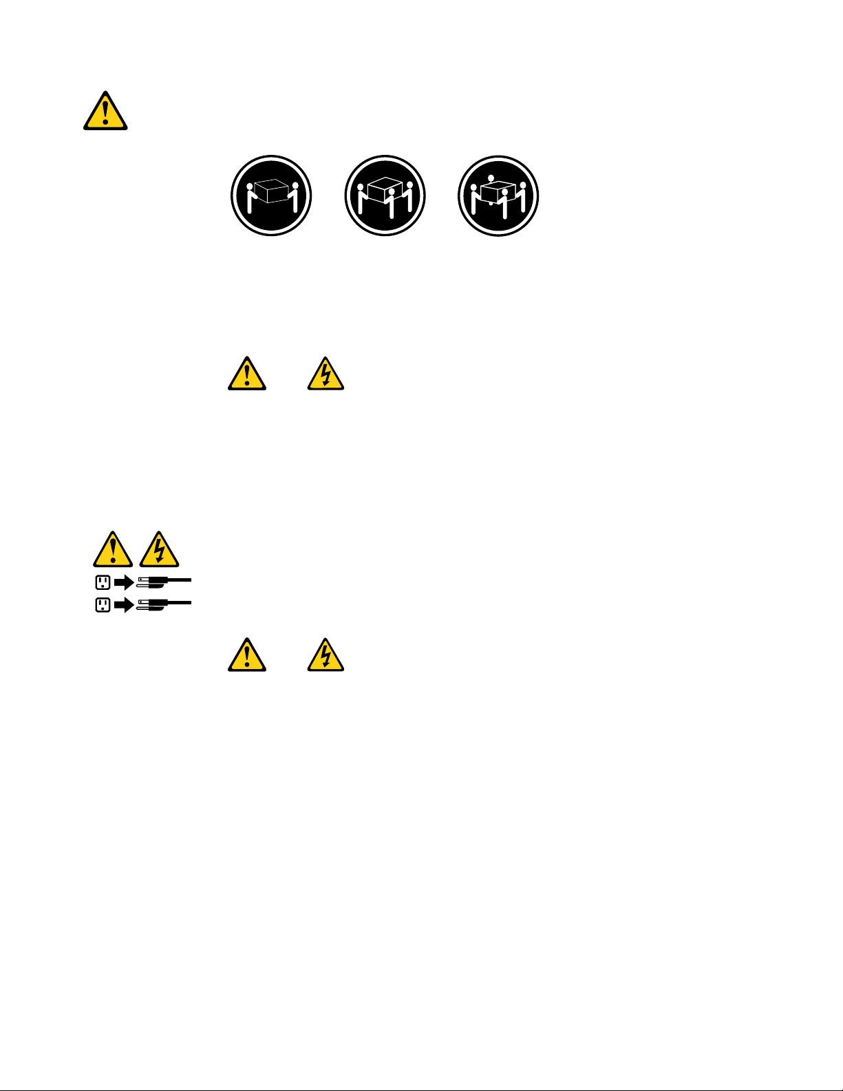
≥18kg(37lbs)≥32kg(70.5lbs)≥55kg(121.2lbs)
CUIDADO:
Utilizeprocedimentosdesegurançaparalevantarequipamentos.
CUIDADO:
Obotãodecontroledealimentaçãododispositivoeobotãoparaligar/desligardafontedealimentação
nãodesligamacorrenteelétricafornecidaaodispositivo.Odispositivotambémpodetermaisdeumcabo
dealimentação.Pararemovertodaacorrenteelétricadodispositivo,assegurequetodososcabosde
alimentaçãoestejamdesconectadosdafontedealimentação.
12HardwareMaintenanceManualLenovo3000JSeries
Page 19
Chapter2.Safetyinformation13
Page 20
1
2
14HardwareMaintenanceManualLenovo3000JSeries
Page 21
Chapter2.Safetyinformation15
Page 22
1
2
DANGER
Lecourantélectriqueprovenantdel'alimentation,dutéléphoneetdescâblesdetransmissionpeutprésenter
undanger.
Pourévitertoutrisquedechocélectrique:
•Nemanipulezaucuncâbleetn'effectuezaucuneopérationd'installation,d'entretienoudereconguration
deceproduitaucoursd'unorage.
•Brancheztouslescordonsd'alimentationsurunsocledeprisedecourantcorrectementcâbléetmisàla
terre.
•Branchezsurdessoclesdeprisedecourantcorrectementcâbléstoutéquipementconnectéàceproduit.
•Lorsquecelaestpossible,n'utilisezqu'uneseulemainpourconnecteroudéconnecterlescâbles
d'interface.
•Nemettezjamaisunéquipementsoustensionencasd'incendieoud'inondation,ouenprésencede
dommagesmatériels.
•Avantderetirerlescartersdel'unité,mettezcelle-cihorstensionetdéconnectezsescordons
d'alimentation,ainsiquelescâblesquilarelientauxréseaux,auxsystèmesdetélécommunicationetaux
modems(saufinstructioncontrairementionnéedanslesprocéduresd'installationetdeconguration).
•Lorsquevousinstallez,quevousdéplacez,ouquevousmanipulezleprésentproduitoudespériphériques
quiluisontraccordés,reportez-vousauxinstructionsci-dessouspourconnecteretdéconnecterles
différentscordons.
16HardwareMaintenanceManualLenovo3000JSeries
Page 23
ConnexionDéconnexion
1.MettezlesunitésHORSTENSION.
2.Commencezparbranchertouslescordonssurles
unités.
3.Branchezlescâblesd'interfacesurdesconnecteurs.
4.Branchezlescordonsd'alimentationsurdesprises.
5.MettezlesunitésSOUSTENSION.
1.MettezlesunitésHORSTENSION.
2.Débranchezlescordonsd'alimentationdesprises.
3.Débranchezlescâblesd'interfacedesconnecteurs.
4.Débrancheztouslescâblesdesunités.
ATTENTION:
Remplacerlapileaulithiumusagéeparunepilederéférenceidentiqueexclusivement,(référence
45C1566),ousuivrelesinstructionsdufabricantquiendénitleséquivalences.Sivotresystèmeest
dotéd'unmodulecontenantunepileaulithium,vousdevezleremplaceruniquementparunmodule
identique,produitparlemêmefabricant.Lapilecontientdulithiumetpeutexploserencasde
mauvaiseutilisation,demauvaisemanipulationoudemiseaurebutinappropriée.
Nepas:
•lajeteràl'eau,
•l'exposeràdestempératuressupérieuresà100°C,
•chercheràlaréparerouàladémonter.
Nepasmettrelapileàlapoubelle.Pourlamiseaurebut,sereporteràlaréglementationenvigueur.
ATTENTION:
Sidesproduitsàlaser(telsquedesunitésdeCD-ROM,deDVD-ROM,desunitésàbresoptiques,ou
desémetteurs)sontinstallés,prenezconnaissancedesinformationssuivantes:
•Neretirezpaslecarter.Enouvrantl'unitédeCD-ROMoudeDVD-ROM,vousvousexposezau
rayonnementdangereuxdulaser.Aucunepiècedel'unitén'estréparable.
•Pourévitertoutrisqued'expositionaurayonlaser,respectezlesconsignesderéglageet
d'utilisationdescommandes,ainsiquelesprocéduresdécritesdansleprésentmanuel.
DANGER
Certainsproduitsàlasercontiennentunediodeàlaserintégréedeclasse3Aou3B.Prenez
connaissancedesinformationssuivantes:
Rayonnementlaserlorsquelecarterestouvert.Eviteztouteexpositiondirecteaurayonlaser.Evitez
deregarderxementlefaisceauoudel'observeràl'aided'instrumentsoptiques.
Chapter2.Safetyinformation17
Page 24
≥18kg(37lbs)≥32kg(70.5lbs)≥55kg(121.2lbs)
1
2
ATTENTION:
Soulevezlamachineavecprécaution.
ATTENTION:
L'interrupteurdecontrôled'alimentationdel'unitéetl'interrupteurdublocd'alimentationnecoupent
paslecourantélectriquealimentantl'unité.Enoutre,lesystèmepeutêtreéquipédeplusieurs
cordonsd'alimentation.Pourmettrel'unitéhorstension,vousdevezdéconnectertouslescordons
delasourced'alimentation.
VORSICHT
AnNetz-,Telefon-undDatenleitungenkönnengefährlicheSpannungenanliegen.
AusSicherheitsgründen:
•BeiGewitterandiesemGerätkeineKabelanschließenoderlösen.FernerkeineInstallations-,
Wartungs-oderRekongurationsarbeitendurchführen.
•GerätnuraneineSchutzkontaktsteckdosemitordnungsgemäßgeerdetemSchutzkontakt
anschließen.
•AlleangeschlossenenGeräteebenfallsanSchutzkontaktsteckdosenmitordnungsgemäß
geerdetemSchutzkontaktanschließen.
•DieSignalkabelnachMöglichkeiteinhändiganschließenoderlösen,umeinenStromschlagdurch
BerührenvonOberächenmitunterschiedlichemelektrischemPotenzialzuvermeiden.
•Geräteniemalseinschalten,wennHinweiseaufFeuer,WasseroderGebäudeschädenvorliegen.
18HardwareMaintenanceManualLenovo3000JSeries
Page 25
•DieVerbindungzudenangeschlossenenNetzkabeln,T elekommunikationssystemen,Netzwerken
undModemsistvordemÖffnendesGehäuseszuunterbrechen,sofernindenInstallations-und
KongurationsprozedurenkeineanderslautendenAnweisungenenthaltensind.
•ZumInstallieren,TransportierenundÖffnenderAbdeckungendesComputersoderder
angeschlossenenEinheitendieKabelgemäßderfolgendenTabelleanschließenundabziehen.
ZumAnschließenderKabelgehenSiewiefolgtvorZumAbziehenderKabelgehenSiewiefolgtvor
1.SchaltenSiealleEinheitenAUS.
2.SchließenSieerstalleKabelandieEinheitenan.
3.SchließenSiedieSignalkabelandieBuchsenan.
4.SchließenSiedieNetzkabelandieSteckdosean.
5.SchaltenSiedieEinheitEIN.
1.SchaltenSiealleEinheitenAUS.
2.ZiehenSiezuerstalleNetzkabelausden
Netzsteckdosen.
3.ZiehenSiedieSignalkabelausdenBuchsen.
4.ZiehenSiealleKabelvondenEinheitenab.
CAUTION:
EineverbrauchteLithiumbatterienurdurcheineBatteriemitderTeilenummer45C1566odereine
gleichwertige,vomHerstellerempfohleneBatterieersetzen.EnthältdasSystemeinModulmiteiner
Lithiumbatterie,diesesnurdurcheinModuldesselbenTypsundvondemselbenHerstellerersetzen.
DieBatterieenthältLithiumundkannbeiunsachgemäßerVerwendung,HandhabungoderEntsorgung
explodieren.
DieBatterienicht:
•mitWasserinBerührungbringen.
•über100Cerhitzen.
•reparierenoderzerlegen.
DieörtlichenBestimmungenfürdieEntsorgungvonSondermüllbeachten.
ACHTUNG:
BeiderInstallationvonLasergeräten(wieCD-ROM-Laufwerken,DVD-aufwerken,Einheitenmit
LichtwellenleitertechnikoderSendern)Folgendesbeachten:
•DieAbdeckungennichtentfernen.DurchEntfernenderAbdeckungendesLasergerätskönnen
gefährlicheLaserstrahlungenfreigesetztwerden.DasGerätenthältkeinezuwartendenTeile.
•WerdenSteuerelemente,EinstellungenoderDurchführungenvonProzedurenandersalshier
angegebenverwendet,kanngefährlicheLaserstrahlungauftreten.
VORSICHT
EinigeLasergeräteenthalteneineLaserdiodederKlasse3Aoder3B.BeachtenSieFolgendes:
Chapter2.Safetyinformation19
Page 26
LaserstrahlungbeigeöffneterVerkleidung.NichtindenStrahlblicken.KeineLupenoderSpiegel
1
2
verwenden.Strahlungsbereichmeiden.
≥18kg(37lbs)≥32kg(70.5lbs)≥55kg(121.2lbs)
ACHTUNG:
ArbeitsschutzrichtlinienbeimAnhebenderMaschinebeachten.
ACHTUNG:
MitdemNetzschalteranderEinheitundamNetzteilwirddieStromversorgungfürdieEinheit
nichtunterbrochen.DieEinheitkannauchmitmehrerenNetzkabelnausgestattetsein.Umdie
StromversorgungfürdieEinheitvollständigzuunterbrechen,müssenallezumGerätführenden
NetzkabelvomNetzgetrenntwerden.
20HardwareMaintenanceManualLenovo3000JSeries
Page 27
Chapter2.Safetyinformation21
Page 28
1
2
PERICOLO
Lacorrenteelettricaprovenientedaicavidialimentazione,deltelefonoedicomunicazionepuòessere
pericolosa.
Perevitareilrischiodiscosseelettriche:
•Noncollegareoscollegarequalsiasicavooppureeffettuarel'installazione,lamanutenzioneola
ricongurazionedelprodottoduranteuntemporale.
•Collegaretuttiilielettriciaunapresadialimentazionecorrettamentecablataedotatadimessaa
terra.
•Collegareallepreseelettricheappropriatetutteleapparecchiaturecheverrannoutilizzateper
questoprodotto.
22HardwareMaintenanceManualLenovo3000JSeries
Page 29
•Sepossibile,utilizzaresolounamanopercollegareoscollegareicavidisegnale.
•Nonaccendereassolutamenteapparecchiatureinpresenzadiincendi,perdited'acquaodanno
strutturale.
•Scollegareicavidialimentazione,isistemiditelecomunicazione,leretieilmodemprimadi
aprireicoperchideldispositivo,salvoistruzionicontrarierelativealleprocedurediinstallazionee
congurazione.
•Collegareescollegareicavicomedescrittonellaseguentetabellaquandovengonoeffettuate
operazionidiinstallazione,spostamentooaperturadeicoperchidiquestoprodottoodelleunità
collegate.
PercollegarsiPerscollegarsi
1.SPEGNEREleapparecchiature.
2.Innanzitutto,collegaretuttiicavialleunità.
3.Collegareicavidisegnaleaiconnettori.
4.Collegareicavidialimentazioneallapresa.
5.Accenderel'unità.
1.SPEGNEREleapparecchiature.
2.Innanzitutto,rimuovereicavidialimentazionedalla
presa.
3.Rimuovereicavidisegnaledaiconnettori.
4.Rimuoveretuttiicavidalleunità.
ATTENZIONE:
Quandosisostituiscelabatteriaallitio,utilizzaresoloilNumeroparte45C1566ountipodibatteria
equivalenteconsigliatodalproduttore.Sesulsistemaèpresenteunmodulochecontieneunabatteria
allitio,sostituirlosoloconuntipodimodulodellostessotipodellastessacasadiproduzione.La
batteriacontienelitioepuòesplodereseusata,maneggiataosmaltitainmodononcorretto.
Non:
•Gettareoimmergerelabatterianell'acqua
•Riscaldarlaadunatemperaturasuperioreai100gradiC(212gradiF)
•Smontarla,ricaricarlaotentarediripararla
Lebatterieusatevannosmaltiteinaccordoallanormativainvigore(DPR915/82esuccessive
disposizioniedisposizionilocali).
ATTENZIONE:
Quandovengonoinstallatiprodottilaser(qualiCD-ROM,unitàDVD-ROM,unitàabreotticheo
trasmittenti),tenerpresentequantosegue:
•Nonrimuovereglisportelli.L'aperturadiun'unitàlaserpuòdeterminarel'esposizionearadiazioni
laserpericolose.All'internodell'unitànonvisonopartisucuieffettuarel'assistenzatecnica.
•L'utilizzodicontrolli,regolazioniol'esecuzionediprocedurenondescrittinelpresentemanuale
possonoprovocarel'esposizionearadiazionipericolose.
Chapter2.Safetyinformation23
Page 30
PERICOLO
1
2
AlcuneunitàlasercontengonoundiodolaserdiClasse3AoClasse3B.Tenerpresentequantosegue:
Aprendol'unitàvengonoemesseradiazionilaser.Nonssareilfascio,nonguardarlodirettamente
construmentiotticiedevitarel'esposizionealfascio.
≥18kg(37lbs)≥32kg(70.5lbs)≥55kg(121.2lbs)
ATTENZIONE:
Prestareattenzionenelsollevarel'apparecchiatura.
ATTENZIONE:
Ilpulsantedicontrollodell'alimentazionepresentesull'unitàel'interruttoredell'alimentatorenon
disattivanol'alimentazionecorrentefornitaall'unità.E'possibilechel'unitàdispongadipiùcavidi
alimentazione.Perdisattivarel'alimentazionedall'unità,accertarsichetuttiicavidialimentazione
sianoscollegatidallafontedialimentazione.
24HardwareMaintenanceManualLenovo3000JSeries
Page 31

Chapter2.Safetyinformation25
Page 32

1
2
PELIGRO
Lacorrienteeléctricaprocedentedecablesdealimentación,teléfonosycablesdecomunicaciónpuede
serpeligrosa.
Paraevitarelriesgodedescargaeléctrica:
•Noconectenidesconecteloscablesnirealiceningunatareadeinstalación,mantenimientoo
reconguracióndeesteproductoduranteunatormentaeléctrica.
•Conectetodosloscablesdealimentaciónatomasdecorrientedebidamentecableadasy
conectadasatierra.
•Cualquierequipoqueseconecteaesteproductotambiéndebeconectarseatomasdecorriente
debidamentecableadas.
•Siemprequeseaposible,utiliceunasolamanoparaconectarodesconectarloscablesdeseñal.
•Noenciendanuncaunequipocuandohayseñalesdefuego,aguaodañosestructurales.
26HardwareMaintenanceManualLenovo3000JSeries
Page 33

•Desconecteloscablesdealimentación,lossistemasdetelecomunicaciones,lasredesylos
módemsconectadosantesdeabrirlascubiertasdelosdispositivos,amenosqueseindiquelo
contrarioenlosprocedimientosdeinstalaciónyconguración.
•Conecteydesconecteloscables,comosedescribeenlatablasiguiente,cuandoinstale,muevao
abralascubiertasdeesteproductoodelosdispositivosconectados.
ParaconectarParadesconectar
1.APÁGUELOtodo.
2.Enprimerlugar,conectetodosloscablesalos
dispositivos.
3.Conecteloscablesdeseñalalosconectores.
4.Enchufeloscablesdealimentaciónalastomasde
corriente.
5.Enciendaeldispositivo.
1.APÁGUELOtodo.
2.Enprimerlugar,desenchufeloscablesdealimentación
delastomasdecorriente.
3.Desconecteloscablesdeseñaldelosconectores.
4.Desconectetodosloscablesdelosdispositivos.
PRECAUCIÓN:
Cuandosustituyaunabateríadelitio,utilicesolamenteunabateríanúmerodepieza45C1566uotra
detipoequivalenterecomendadaporelfabricante.Sisusistemadisponedeunmóduloquecontiene
unabateríadelitio,reemplácelosóloconelmismotipodemódulo,delmismofabricante.Labatería
contienelitioypuedeexplotarsinoseutiliza,manipulaodesechacorrectamente.
Nodebe:
•Arrojarlaalaguaosumergirlaenella
•Exponerlaatemperaturassuperioresa100°C(212°F)
•Repararlaodesmontarla
Deshágasedelabateríasegúnespeciquenlasleyesonormaslocales.
PRECAUCIÓN:
Cuandohayaproductosláser(comounidadesdeCD-ROM,unidadesdeDVD,dispositivosdebra
ópticaotransmisores)instalados,tengaencuentalosiguiente:
•Noquitelascubiertas.Siquitalascubiertasdelproductoláser,podríaquedarexpuestoaradiación
láserpeligrosa.Dentrodeldispositivonoexisteningunapiezaquerequieraserviciotécnico.
•Siusacontrolesoajustesorealizaprocedimientosquenoseanlosespecicadosaquí,podría
exponersearadiacionespeligrosas.
PELIGRO
Chapter2.Safetyinformation27
Page 34

Algunosproductoslásertienenincorporadoundiodoláserdeclase3Aoclase3B.T engaencuentalo
1
2
siguiente:
Cuandoseabre,quedaexpuestoaradiaciónláser.Nomiredirectamentealrayoláser,nisiquieracon
instrumentosópticos,yeviteexponersedirectamentealrayoláser.
≥18kg(37lbs)≥32kg(70.5lbs)≥55kg(121.2lbs)
PRECAUCIÓN:
Adopteprocedimientossegurosallevantarelequipo.
PRECAUCIÓN:
Elbotóndecontroldealimentacióndeldispositivoyelinterruptordealimentacióndelafuentede
alimentaciónnodesconectanlacorrienteeléctricasuministradaaldispositivo.Además,eldispositivo
podríatenermásdeuncabledealimentación.Parasuprimirtodalacorrienteeléctricadeldispositivo,
asegúresedequetodosloscablesdealimentaciónesténdesconectadosdelatomadecorriente.
28HardwareMaintenanceManualLenovo3000JSeries
Page 35

Chapter3.Generalinformation
Thischapterprovidesgeneralinformationthatappliestoallmachinetypessupportedbythispublication.
TheLenovoCareprogram
UsetheLenovoCareprogramforgeneralinformationabouttheuse,operation,andmaintenanceofthe
computer.TheLenovoCareprogramalsocontainsinformationtohelpsolveproblemsandgetrepair
serviceorothertechnicalassistance.TheLenovoCareprogramispreinstalledonmostLenovo3000J
Seriesproducts.
Additionalinformationresources
IfyouhaveInternetaccess,themostup-to-dateinformationforthecomputerisavailablefromtheWorld
WideWeb.
Youcanndthefollowinginformation:
•CRUremovalandinstallationinstructions
•Publications
•Troubleshootinginformation
•Partsinformation
•Downloadsanddrivers
•Linkstootherusefulsourcesofinformation
Toaccessthisinformation,pointyourbrowserto
http://www.lenovo.com/support/.
Specications
Thissectionliststhephysicalspecicationsforthecomputer.
©CopyrightLenovo2006,2010
29
Page 36

Machinetypes7387,7388,7389,7393,7394,and7395
Dimensions
Width:180mm(7.09in.)
Height:392mm(15.43in.)
Depth:445mm(17.52in.)
Weight
Minimumcongurationasshipped:9.1kg(20.06lbs)
Maximumconguration:10.2kg(22.5lbs)
Environment
•Airtemperature:
–Systemon:10°to35°C(50°to95°F)
–Systemoff:10°to60°C(50°to140°F)
–Maximumaltitude:914m(3000ft)
Note:Themaximumaltitude,914m(3000ft),isthemaximumaltitudeatwhichthespeciedairtemperatures
apply.Athigheraltitudes,themaximumairtemperaturesarelowerthanthosespecied.
•Humidity:
Systemon:10%to80%
Systemoff:10%to90%
Electricalinput
•Inputvoltage:
–Lowrange:
Minimum:100Vac
Maximum:127Vac
Inputfrequency:50-60Hz
Voltageswitchsetting:115Vac
–Highrange:
Minimum:200Vac
Maximum:240Vac
Inputfrequency:50-60Hz
Voltageswitchsetting:230Vac
–Inputkilovolt-amperes(kVA)(approximate):
Minimumcongurationasshipped:0.158kVA
Maximumconguration:0.213kVA
Machinetypes7390,7391,7392,7396,7397,and7398
Thissectionliststhephysicalspecicationsforthecomputer.
30HardwareMaintenanceManualLenovo3000JSeries
Page 37

Dimensions
Width:331mm(13.0in.)
Height:108mm(4.3in.)
Depth:405mm(15.9in.)
Weight
Minimumcongurationasshipped:8.2kg(18.0lbs)
Maximumconguration:8.3kg(18.2lbs)
Environment
•Airtemperature:
Operatingat0-3000ft(914.4m):10°to35°C(50°to95°F)
Operatingat3000ft-7000ft(2134m):10°to32°C(50°to89.6°F)
Non-operating:10°to43°C(50°to110°F)
•Humidity:
Operating:10%to80%
Non-operating:10%to90%
Transit:8%to90%
•Maximumaltitude:7000ft(2133.6m)
Electricalinput
•Inputvoltage:
–Lowrange:
Minimum:100Vac
Maximum:127Vac
Inputfrequency:50/60Hz
Voltageswitchsetting:115Vac
–Highrange:
Minimum:200Vac
Maximum:240Vac
Inputfrequency:50/60Hz
Voltageswitchsetting:230Vac
–Inputkilovolt-amperes(kVA)(approximate):
Minimumcongurationasshipped:0.09kVA
Maximumconguration:0.23kVA
Chapter3.Generalinformation31
Page 38

32HardwareMaintenanceManualLenovo3000JSeries
Page 39

Chapter4.GeneralCheckout
Attention
Thedrivesinthecomputeryouareservicingmighthavebeenrearrangedorthedrivestartupsequence
changed.Beextremelycarefulduringwriteoperationssuchascopying,saving,orformatting.Dataor
programscanbeoverwrittenifyouselectanincorrectdrive.
Generalerrormessagesappearifaproblemorconictisfoundbyanapplicationprogram,theoperating
system,orboth.Foranexplanationofthesemessages,refertotheinformationsuppliedwiththatsoftware
package.
BeforereplacinganyFRUs,ensurethatthelatestlevelofBIOSisinstalledonthesystem.Adown-levelBIOS
mightcausefalseerrorsandunnecessaryreplacementofthesystemboard.Formoreinformationonhowto
determineandobtainthelatestlevelBIOS,see“BIOSlevels”onpage185
Usethefollowingproceduretohelpdeterminethecauseoftheproblem:
1.Power-offthecomputerandallexternaldevices.
2.Checkallcablesandpowercords.
3.Setalldisplaycontrolstothemiddleposition.
4.Power-onallexternaldevices.
5.Power-onthecomputer.
•Lookfordisplayederrorcodes
•Listenforbeepcodes
•Lookforreadableinstructionsoramainmenuonthedisplay.
Ifyoudidnotreceivethecorrectresponse,proceedtostep6onpage33
Ifyoudoreceivethecorrectresponse,proceedtostep7onpage33.
6.Lookatthefollowingconditionsandfollowtheinstructions:
.
.
•IfyouhearbeepcodesduringPOST,goto“Beepsymptoms”onpage63
•IfthecomputerdisplaysaPOSTerror,goto“POSTerrorcodes”onpage64.
•Ifthecomputerhangsandnoerrorisdisplayed,continueatstep7onpage33.
7.RuntheDiagnosticprograms.SeeChapter5“Diagnostics”onpage35.
•Ifyoureceiveanerror,replacethepartthatthediagnosticprogramcallsoutorgoto“Diagnostic
errorcodes”onpage46.
•Iftheteststopsandyoucannotcontinue,replacethelastdevicetested.
.
Problemdeterminationtips
Duetothevarietyofhardwareandsoftwarecombinationsthatcanbeencountered,usethefollowing
informationtoassistyouinproblemdetermination.Ifpossible,havethisinformationavailablewhen
requestingassistancefromServiceSupportandEngineeringfunctions.
•Machinetypeandmodel
•Processororharddiskupgrades
•Failuresymptom
–Dodiagnosticsindicateafailure?
–What,when,where,single,ormultiplesystems?
–Isthefailurerepeatable?
©CopyrightLenovo2006,2010
33
Page 40

–Hasthiscongurationeverworked?
–Ifithasbeenworking,whatchangesweremadepriortoitfailing?
–Isthistheoriginalreportedfailure?
•Diagnosticsversion
–Typeandversionlevel
•Hardwareconguration
–Print(printscreen)congurationcurrentlyinuse
–BIOSlevel
•Operatingsystemsoftware
–Typeandversionlevel
Notes:Toeliminateconfusion,identicalsystemsareconsideredidenticalonlyifthey:
1.Aretheexactmachinetypeandmodels
2.HavethesameBIOSlevel
3.Havethesameadapters/attachmentsinthesamelocations
4.Havethesameaddressjumpers/terminators/cabling
5.Havethesamesoftwareversionsandlevels
6.HavethesameDiagnosticDiskettes(version)
7.Havethesamecongurationoptionssetinthesystem
8.Havethesamesetupfortheoperatingsystemcontrolles
Comparingthecongurationandsoftwareset-upbetween“workingandnon-working”systemswilloften
leadtoproblemresolution.
34HardwareMaintenanceManualLenovo3000JSeries
Page 41

Chapter5.Diagnostics
Diagnosticprogramsareusedtotesthardwarecomponentsofthecomputerandreport
operating-system-controlledsettingsthatcancausehardwarefailures.Therearetwodiagnosticprograms
preinstalledonthecomputertohelpdiagnoseproblems:
•PC-Doctorfor®Windows(usedwhendiagnosingproblemswhilerunningtheWindowsoperatingsystem)
•PC-DoctorforDOSorPC-DoctorforWindowsPE,dependinguponyourmachinetypeandmodel(used
whenyourWindowsoperatingsystemwillnotstart)
Notes:
1.YoucandownloadthelatestversionofthePC-DoctorforWindowsandPC-DoctorforDOSdiagnostic
programsfromhttp://www.lenovo.com/support/.T ypeyourmachinetypeintotheUseQuickPatheld
andclickGotondthedownloadablelesthatarespecictothecomputer.
2.LoglesarecreatedwhenyourunPC-DoctorforWindowsanddependinguponyourmachinetype
andmodel,PC-DoctorforDOSorPC-DoctorforWindowsPE.Saveandprinttheloglescreated
bybothdiagnosticprograms.TheloglecreatedbyPC-DoctorforWindowsisautomaticallysaved
inC:\PCDR\DETAILED.TXT .
PC-DoctorforWindows
PC-DoctorforWindowsisadiagnosticprogramthatworksthroughtheWindowsoperatingsystem.The
PC-DoctorforWindowsdiagnosticprogramenablesyoutoviewsymptomsandsolutionsforcomputer
problems,accesstheLenovotroubleshootingcenter,updatesystemdrivers,andreviewsysteminformation.
TorunPC-DoctorforWindows,opentheStartmenufromtheWindowsdesktop,selectAllPrograms,select
PC-DoctorforWindows,andclickPC-DoctorforWindows.Followtheinstructionsonthescreen.
Foradditionalinformationaboutrunningthediagnosticprogram,refertothePC-DoctorforWindows
helpsystem.
IfyoustillsuspectaproblemafterPC-DoctorforWindowsrunssuccessfully,runPC-DoctorforDOSor
PC-DoctorforWindowsPEtohelpyoudiagnosethecomputerproblem.
PC-DoctorforDOS
Dependinguponyourmachinetypeandmodel,youeitherhavePC-DoctorforDOSorPC-Doctorfor
WindowsPEoneachLenovocomputer.ThePC-DoctorforDOSdiagnosticprogramispartoftheRescue
andRecovery™workspaceandrunsindependentlyoftheWindowsoperatingsystem.UsePC-Doctorfor
DOS,ifyouareunabletostarttheWindowsoperatingsystemorifPC-DoctorforWindowshasnotbeen
successfulinisolatingapossibleproblem.YoucanrunPC-DoctorforDOSfromadiagnosticCDimageor
diagnosticdiskettesthathavebeencreated.YoucanalsorunPC-DoctorforDOSfromtheRescueand
Recoveryworkspace.
Note:ItisimportanttocreateadiagnosticCDimageordiagnosticdiskettesincasePC-DoctorforDOS
cannotberunfromtheRescueandRecoveryworkspace.
CreatingadiagnosticCDimage
TocreateadiagnosticCDimage,downloadaself-startingbootableCDimage(knownasan.isoimage)
ofthediagnosticprogramfromhttp://www.lenovo.com/support/.Afteryoudownloadtheimage,you
cancreatetheCDusinganyCDburningsoftware.
©CopyrightLenovo2006,2010
35
Page 42

IfthecomputerdoesnothaveaCDburneroryoudonothaveInternetaccess,see“Creatingdiagnostic
diskettes”onpage36.
Creatingdiagnosticdiskettes
Tocreatediagnosticdiskettes,downloadthePC-DoctorforDOSdiagnosticprogramfrom
http://www.lenovo.com/support/ontotwoblank,formatteddiskettes.
IfyoudonothaveInternetaccess,createthediagnosticdiskettesusingthefollowingprocedure:
Note:YouwillneedadiskettedriveonthecomputeroraUSBdiskettedrivetocompletethisprocedure.
1.Shutdowntheoperatingsystemandturnoffthecomputer.
2.IfyouareusingaUSBdiskettedrive,plugitintothecomputer.
3.RepeatedlypressandreleasetheF11keyasyouturnonthecomputer.
4.Whenyouhearbeepsorseealogoscreen,stoppressingtheF11key.TheRescueandRecovery
workspaceopens.
Note:Forsomemodels,presstheEsckeytoenterRescueandRecovery.
5.FromtheRescueandRecoveryworkspace,selectCreatediagnosticdisks.
6.Followtheinstructionsonthescreen.
7.Whenprompted,insertablank,formatteddisketteintothediskettedriveandcontinuetofollowthe
instructionsonthescreen.
8.Whentheoperationiscomplete,removethedisketteandclickQuit.
9.Insertanotherblank,formatteddisketteintothediskettedriveandcontinuetofollowtheinstructionson
thescreen.
10.Whentheoperationiscomplete,removethedisketteandclickQuit.
RunningdiagnosticsfromtheCDordiskettes
1.IfyouarerunningdiagnosticsfromdiskettesusingaUSBdiskettedrive,plugintheUSBdrive.
Note:Theopticaldriveordiskettedrivemustbeselectedinthestartupsequence.See“Changingthe
startupdevicesequence”onpage43forinstructionsonhowtoselectthestartupdevice.
2.InserttheCDordiskette.
3.Restartthecomputer.
4.Whenthediagnosticsprogramopens,followtheinstructionsonthescreen.
Note:Ifyouarerunningdiagnosticsfromadiskette,whenprompted,removetherstdisketteand
inserttheseconddiskette.
5.Selectthediagnostictestyouwanttorun.PresstheF1keyforadditionalhelp.
6.RemovetheCDordiskettewhentheprogramnishes.
RunningdiagnosticsfromtheRescueandRecoveryworkspace
IfyoudonothaveadiagnosticCDimageordiagnosticdiskette,youcanrunthePC-DoctorforDOS
diagnosticprogramfromtheRescueandRecoveryworkspace.TorundiagnosticsfromtheRescueand
Recoveryworkspace,usethefollowingprocedure:
1.Shutdowntheoperatingsystemandturnoffthecomputer.
2.RepeatedlypressandreleasetheF11keyasyouturnonthecomputer.
3.Whenyouhearbeepsorseealogoscreen,stoppressingtheF11key.TheRescueandRecovery
workspaceopens.
36HardwareMaintenanceManualLenovo3000JSeries
Page 43

Note:Forsomemodels,presstheEsckeytoenterRescueandRecovery.
4.FromtheRescueandRecoveryworkspace,selectDiagnosehardware.
5.Followthepromptsonthescreen.Thecomputerwillreboot.
6.Whenthecomputerrestarts,thediagnosticprogramopensautomatically.Selectthediagnostictestyou
wanttorun.PresstheF1keyforadditionalhelp.
PC-DoctorforWindowsPE
Dependinguponyourmachinetypeandmodel,youeitherhavePC-DoctorforDOSorPC-Doctorfor
WindowsPEoneachLenovocomputer.ThePC-DoctorforWindowsPEdiagnosticprogramispartofthe
RescueandRecoveryworkspace.UsePC-DoctorforWindowsPE,ifyouareunabletostarttheWindows
operatingsystemorifPC-DoctorforWindowshasnotbeensuccessfulinisolatingapossibleproblem.
RunningdiagnosticsfromtheRescueandRecoveryworkspace
YoucanrunthePC-DoctorforWindowsPEdiagnosticprogramfromtheRescueandRecoveryworkspace.
TorundiagnosticsfromtheRescueandRecoveryworkspace,usethefollowingprocedure:
1.Shutdowntheoperatingsystemandturnoffthecomputer.
2.RepeatedlypressandreleasetheF11keyasyouturnonthecomputer.
3.Whenyouhearbeepsorseealogoscreen,stoppressingtheF11key.TheRescueandRecovery
workspaceopens.
4.FromtheRescueandRecoveryworkspace,selectDiagnosehardware.
5.Thediagnosticprogramopensautomatically.Selectthediagnostictestyouwanttorun.PresstheF1
keyforadditionalhelp.
6.Followtheinstructionsonthescreen.
Note:RescuemediaincludesPC-DoctorforWindowsPE.Formoreinformationaboutrescuemedia,
seetheUserGuideforthecomputer.
Navigatingthroughthediagnosticsprograms
Usethecursormovementkeystonavigatewithinthemenus.
•TheEnterkeyisusedtoselectamenuitem.
•TheEsckeyisusedtobackuptothepreviousmenu.
•ForonlinehelpselectF1.
Runningtests
Therearefourwaystorunthediagnostictests.
•Usingthecursormovementkeys,highlightRunNormalTestorRunQuickT estfromtheDiagnostics
menuandthenpressEnter.Thisautomaticallyrunsapre-denedgroupoftestsfromeachtestcategory.
RunNormalTestrunsamoreextensivesetofteststhandoesRunQuickTestandtakeslongerto
complete.
•PressF5toautomaticallyrunallselectedtestsinallcategories.
•Fromwithinatestcategory,pressCtrl-Entertoautomaticallyrunonlytheselectedtestsinthatcategory.
•Usingthecursormovementkeys,highlightasingletestwithinatestcategory,andthenpressEnter.
Thisrunsonlythattest.
Chapter5.Diagnostics37
Page 44

PressEscatanytimetostopthetestingprocess.
Testresults(N/A,PASSED,FAILED,ABORTED)aredisplayedintheeldbesidethetestdescriptionandin
thetestlog.See“Viewingthetestlog”onpage40.
Toselectoneormoretests,usethefollowingprocedure.
1.Openthecorrespondingtestcategory.
2.Usingthecursormovementkeys,highlightthedesiredtest.
3.Pressthespacebar.Aselectedtestismarkedby>>.Pressingthespacebaragainde-selectsatest
andremovesthe>>.
4.Repeatsteps2and3abovetoselectalldesiredtests.
Testresults
Diagnosticstestresultsproducethefollowingerrorcodeformat:
FunctionCode
FailureTypeDeviceIDDate
ChkDigits
•FunctionCode:
RepresentsthefeatureorfunctionwithinthePC.
•FailureType:
Representsthetypeoferrorencountered.
•DeviceID:
Containsthecomponent'sunit-IDwhichcorrespondstoeitheraxeddiskdrive,removablemediadrive,
serialorparallelport,processor,specicRIMM,oradeviceonthePCIbus.
•Date:
Containsthedatewhenthediagnostictestwasrun.ThedateisretrievedfromCMOSanddisplayed
usingtheYYYYMMDDformat.
•ChkDigits:
Containsa2-digitcheck-digitvaluetoensurethefollowing:
–Diagnosticswererunonthespecieddate.
–Diagnosticswererunonthespeciedcomputer.
–Thediagnosticerrorcodeisrecordedcorrectly.
•Text:
Descriptionoftheerror.
Note:See“Diagnosticerrorcodes”onpage46forerrorcodelistings.
Text
Fixeddiskadvancedtest(FDAT)
PC-DoctorFixed-Disk
suite.ThecongurablecapabilitiesofFDATallowuserstoenableordisablespecictests,enableordisable
testingfeatures,controlthetestlogdetail,altertestingparameters,andsoon.FDA Ttestsforandreports
mostcommonlyfounderrorsonaxed-diskdriveandisabletotestupto128SCSIand4IDEdrives
(upto132totaldrives).
DriveinformationisgatheredthroughFDAT’senumerationofavailabledevicesanduserspecicconguration
parameterslocatedintheFDAT.INI.FDATusesinformationsuppliedbythesefeaturestoindicatespecically
1.Thetermsxeddiskandharddiskareusedinterchangeably.
38HardwareMaintenanceManualLenovo3000JSeries
1
AdvancedT estmodule(FDAT)isafull-featuredhighlycongurablexed-disktest
Page 45

whatdevicesareavailablefortest,whattestsareavailableforthedevice,deviceproperties,andsoon.T o
changetestingparameters,youmodifytheFDAT.INIleinPCDoctorforDOS.
FDATconsistsofthefollowingsubtestsandfeatures.
Fixed-DiskTests:
•SeekTests:-checksthephysicaloperationofthedrivehead.
–LinearSeek
–RandomSeek
–Min-MaxSeek
–ButterySeek
•VerifyTests:-checkstheintegrityofthedatapresentonthemedia.
–LinearVerify
–RandomVerify
•SurfaceScanTests:-checksthedrivemediafordefects.
–SurfaceScan(Linear)
–SurfaceScan(Aggressive)-thisisdisabledfornormalcustomeruse.
–SurfaceScan(Random)
•Self-monitoring,AnalysisandReportingTechnology(SMART)-checkstheSMARTfunctionalityfor
drivesthatsupportSMART.
–StartSMARTSelf-Test
OtherTestFeatures:
•Write-SpliceRepair-detectsandcorrectsErrorCorrectionCodeerrorsduringVerifytests.
•AutoSpinDown-agradualspindownofthedriveplatterstoavoiddamagingthemedia.
•ManufacturerLog-anin-depthmanufacturersupportedlogoferrorsonthedrive.
Multitasking:
Toallowsimultaneoustestingofmultipleharddriveswheneverpossible,theFDATmoduleiswrittenasa
setofmultitaskingfunctions.Eachdriveundertestcanrunthesametestorrunadifferenttestatthe
sametime.Eachsubtestiswrittentohandleasingletestpassandalltestvariablesarekepttrackofina
structureuniqueforeachdrive.
However,whentestingIDEdrives,FDATwillnotperformsimultaneoustestingofIDEdrivesthatareattached
tothesameIDEcable.Forexample,ifFDATistestingfourIDEdrivesonaPC,itwillperformsimultaneous
testingondrives1and3rst(masterdrives),thenperformtestson2and4(slavedrives).FDATwillalso
performsimultaneoustestingonamasterandslavethatareonseparateIDEcables,butwillnotperform
simultaneoustestsonamasterandslaveonthesameIDEcable.Thisgenerallyincreasestheamountof
timeneededtotestmultipleIDEdrives.
AnotherlimitationofFDAT’SmultitaskingcapabilityistheuseofUltraDMA(UDMA).Onlyonedriveata
timecanaccesstheUDMAchannelandtheUDMAchannelbuffermustbekepthighinordertomaintaina
speedadvantageoverotherdatatransfermodes.InordertousetheUDMAchannelduringtesting,users
mustdisablethemultitaskingfeature.
Destructiveversusnon-destructivetesting:
Chapter5.Diagnostics39
Page 46

MostofthetestsfoundinFDATarenon-destructive.ThismeansthatPC-Doctorprogramwillpreserve
anydatathatispresentonthetestedmediapriortobeginninganydestructiveoperations(suchaswrite
operations).However,userscanruncertaintestsindestructivemode(i.e.surfacescantests).Destructive
testswillspeeduptestingbecauseFDATdoesnotpreservethedataonthemediapriortothetestbeginning.
Unlikenon-destructivetests,anydatapresentonthemediapriortothetestbeginningislost.
FDATallowsforenablingordisablingdestructivetests,aswellasspecifyingarangeofdestructive
andnon-destructivesectorsonthetesteddrive.ThisisdonethroughthecongurationoftheFDAT.INI.
Ifdestructiveandnon-destructiverangessomehowoverlap,thentheoverlappedareaisconsidered
non-destructive.Forexample,ifusersspecifybothdestructiveandnon-destructiverangesasthesame,
thentheentiredriveistestedasnon-destructive.
QuickandFullerase-harddrive
Thediagnosticsprogramofferstwoharddriveformatutilities:
•QuickEraseHardDrive
•FullEraseHardDrive
TheQuickEraseHardDriveprovidesaDOSutilitythatperformsthefollowing:
•DestroystheMasterBootRecord(MBR)ontheharddrive.
•DestroysallcopiesoftheFATTableonallpartitions(boththemasterandbackup).
•Destroysthepartitiontable.
•Providesmessagesthatwarntheuserthatthisisanon-recoverableprocess.
TheFullEraseHardDriveprovidesaDOSutilitythatperformsthefollowing:
•PerformsallthestepsinQuickErase.
•ProvidesaDOSutilitythatwritesrandomdatatoallsectorsoftheharddrive.
•Providesanestimateoftimetocompletionalongwithavisualrepresentationofcompletionstatus.
•Providesmessagesthatwarntheuseraboutnon-recoverableprocess.
Important:MakesurethatalldataisbackedupbeforeusingtheQuickorFullErasefunctions.
ToselecttheQuickEraseorFullEraseHardDriveutility,usethefollowingprocedure:
1.SelecttheUTILITYoptiononthetoolbarandpressEnter.
2.SelecteithertheQUICKERASEorFULLERASEHARDDISKoptionandfollowtheinstructions.
Viewingthetestlog
Errorsreportedbythediagnostictestwillbedisplayedbytheprogramasafailedtest.
Toviewdetailsofafailureortoviewalistoftestresults,usethefollowingprocedurefromanytestcategory
screen:
1.PressF3toactivatethelogle.
2.PressF3againtosavetheletodisketteorpressF2toprintthele.
40HardwareMaintenanceManualLenovo3000JSeries
Page 47

Chapter6.UsingtheSetupUtility
TheSetupUtilityprogramisstoredintheelectricallyerasableprogrammableread-onlymemory(EEPROM)
ofthecomputer.TheSetupUtilityprogramisusedtoviewandchangethecongurationsettingsofthe
computer,regardlessofwhichoperatingsystemyouareusing.However,theoperating-systemsettings
mightoverrideanysimilarsettingsintheSetupUtilityprogram.
StartingtheSetupUtilityprogram
TostarttheSetupUtilityprogram,dothefollowing:
1.Ifthecomputerisalreadyonwhenyoustartthisprocedure,shutdowntheoperatingsystemandturn
offthecomputer.
2.PressandholdtheF1keythenturnonthecomputer.Whenyouhearmultiplebeeps,releasetheF1key.
Notes:
a.IfyouareusingaUSBkeyboardandtheSetupUtilityprogramdoesnotdisplayusingthismethod,
repeatedlypressandreleasetheF1keyratherthanleavingitpressedwhenturningonthecomputer.
b.Ifauserpasswordoranadministrator/supervisorpasswordhasbeenset,theSetupUtilityprogram
menuisnotdisplayeduntilyoutypethepassword.See“Usingpasswords”onpage41
information.
TheSetupUtilitymightstartautomaticallywhenPOSTdetectsthathardwarehasbeenremovedornew
hardwarehasbeeninstalledinthecomputer.
formore
Viewingandchangingsettings
TheSetupUtilityprogrammenulistsitemsthatidentifysystemcongurationtopics.
WhenworkingwiththeSetupUtilityprogrammenu,youmustusethekeyboard.Thekeysusedtoperform
varioustasksaredisplayedatthebottomofeachscreen.
Usingpasswords
Passwordsmightbesettoprovidesecurityforthecomputeranddata.Therearetwotypesofpasswords:a
userpasswordandanadministratororsupervisorpassword.Apasswordofeithertypedoesnothavetobe
settousethecomputer.Ifeitherpasswordisset,readthefollowingsections.
UserPassword
Theuserpasswordfeaturedetersunauthorizedpersonsfromgainingaccesstothecomputer.
Setting,changing,anddeletingauserpassword
Toset,change,ordeleteauserpassword,dothefollowing:
Note:Apasswordcanbeanycombinationofuptoeightcharacters(A-Z,a-z,and0-9).
1.StarttheSetupUtilityprogram(see“StartingtheSetupUtilityprogram”onpage41).
2.FromtheSetupUtilityprogrammenu,selectSetUserPasswordandpressEnter.
3.Thepassworddialogboxwillbedisplayed.Typethenewpassword,andpressEnter.
©CopyrightLenovo2006,2010
41
Page 48

4.Whenpromptedtoconrmthepassword,typethepasswordagain.Ifyoutypethepasswordincorrectly,
thepasswordwillbeinstalled.
Todeleteapreviouslysetuserpassword,dothefollowing:
Note:Whenpromptedforapassword,youcantypeeitheryouruseroradministrator/supervisorpassword.
1.FromtheSetupUtilityprogrammenu,selectSetUserPasswordandpressEnter.Amessagewilldisplay
thatindicatesthepasswordhasbeendisabled.
2.Pressanykeytocontinue.
AdministratororSupervisorPassword
SettinganAdministratororSupervisorPassworddetersunauthorizedpersonsfromchangingconguration
settings.
AfteranAdministratororSupervisorPasswordisset,apasswordpromptisdisplayedeachtimeyoutryto
accesstheSetupUtilityprogram.Ifthewrongpasswordistyped,anerrormessageisdisplayed.Ifthe
wrongpasswordistypedthreetimes,youmustturnthecomputeroffandstartagain.
Ifboththeuserandadministrator/supervisorpasswordsareset,eitherpasswordcanbetyped.However,to
changeanycongurationsettings,youmustusetheadministrator/supervisorpassword.
Setting,changing,anddeletinganadministrator/supervisorpassword
Toset,change,ordeleteanadministrator/supervisorpassword,dothefollowing:
Note:Apasswordcanbeanycombinationofuptoeightcharacters(A-Z,a-z,and0-9).
1.StarttheSetupUtilityprogram(see“StartingtheSetupUtilityprogram”onpage41).
2.FromtheSetupUtilityprogrammenu,selectSetAdministratorPasswordorSetSupervisorPassword
andpressEnter.
3.Thepassworddialogboxwillbedisplayed.Typethenewpassword,andpressEnter.
4.Whenpromptedtoconrmthepassword,typethepasswordagain.Ifyoutypethepasswordcorrectly,
thepasswordwillbeinstalled.
Todeleteapreviouslysetadministrator/supervisorpassword,dothefollowing:
Note:Whenpromptedforapassword,youmusttypeyouradministrator/supervisorpassword.
1.FromtheSetupUtilityprogrammenu,selectSetAdministratorPasswordorSetSupervisorPassword
andpressEnter.Amessagewilldisplaythatindicatesthepasswordhasbeendisabled.
2.Pressanykeytocontinue.
Selectingastartupdevice
Ifthecomputerdoesnotstartup(boot)fromadevicesuchastheCD-ROM,diskette,orharddiskas
expected,useoneofthefollowingprocedurestoselectastartupdevice.
Selectingatemporarystartupdevice
Usethisproceduretostartupfromanybootdevice.
Note:NotallCDs,harddisks,anddiskettesarestartable(bootable).
1.Turnoffthecomputer.
2.PressandholdtheF12keythenturnonthecomputer.WhentheStartupDeviceMenu(BootMenu)
appears,releasetheF12key.
42HardwareMaintenanceManualLenovo3000JSeries
Page 49

Note:IfyouareusingaUSBkeyboardandtheStartupDeviceMenudoesnotdisplayusingthismethod,
repeatedlypressandreleasetheF12keyratherthanleavingitpressedwhenturningonthecomputer.
3.SelectthedesiredstartupdevicefromtheStartupDeviceMenuandpressEntertobegin.
Note:SelectingastartupdevicefromtheStartupDevice(Boot)menudoesnotpermanentlychangethe
startupsequence.
Changingthestartupdevicesequence
Tovieworchangetheprimaryorautomaticpower-onstartupsequence,dothefollowing:
1.StarttheSetupUtilityprogram(see“StartingtheSetupUtilityprogram”onpage41).
2.SelectAdvancedBIOSfeatures.
3.SelectthesequenceofdevicesfortheFirstBootDevice,theSecondBootDevice,andtheThirdBoot
Device.
4.PressEsctoreturntotheSetupUtilityprogrammenu.
5.SelectSave&ExitSetup.
Ifyouhavechangedthesesettingsandwanttoreturntothedefaultsettings,press(N)whentheSaveand
Exitdialogboxisdisplayed.
ExitingfromtheSetupUtilityprogram
Whenyounishviewingorchangingsettings,pressEsctoreturntotheSetupUtilityprogrammenu(you
mighthavetopressEscseveraltimes).Ifyouwanttosavethenewsettings,selectSave&ExitSetup
beforeyouexit.Otherwise,yourchangeswillnotbesaved.
Chapter6.UsingtheSetupUtility43
Page 50

44HardwareMaintenanceManualLenovo3000JSeries
Page 51

Chapter7.Symptom-to-FRUIndex
TheSymptom-to-FRUindexlistserrorsymptomsandpossiblecauses.Themostlikelycauseislistedrst.
AlwaysbeginwithChapter4“GeneralCheckout”onpage33
decidewhichFRUstohaveavailablewhenservicingacomputer.Ifyouareunabletocorrecttheproblem
usingthisindex,goto“Undeterminedproblems”onpage67.
Notes:
•Ifyouhavebothanerrormessageandanincorrectaudioresponse,diagnosetheerrormessagerst.
•Ifyoucannotrunthediagnostictestsoryougetadiagnosticerrorcodewhenrunningatest,butdidreceivea
POSTerrormessage,diagnosethePOSTerrormessagerst.
•Ifyoudidnotreceiveanyerrormessage,lookforadescriptionofyourerrorsymptomsintherstpartofthisindex.
Harddiskdrivebooterror
Aharddiskdrivebooterror(errorcodes1962andI999030X)canhavethefollowingcauses.
ErrorFRU/Action
Thestart-updriveisnotinthebootsequencein
conguration.
Nooperatingsysteminstalledonthebootdrive.Installanoperatingsystemonthebootdrive.
Thebootsectoronthestart-updriveiscorrupted.
Thedriveisdefective.
.Thisindexcanalsobeusedtohelpyou
Checkthecongurationandensurethestart-updriveis
inthebootsequence.
Thedrivemustbeformatted,dothefollowing:
1.Attempttoback-upthedataonthefailingharddisk
drive.
2.Usingtheoperatingsystemsprograms,formatthe
harddiskdrive.
Replacetheharddiskdrive.
PowerSupplyProblems
Ifyoususpectapowerproblem,usethefollowingprocedures.
Check/VerifyFRU/Action
Checkthefollowingforproperinstallation.
•PowerCord
•On/OffSwitchconnector
•On/OffSwitchPowerSupplyconnector
•SystemBoardPowerSupplyconnectors
•Microprocessor(s)connection
Checkthepowercordforcontinuity.PowerCord
Checkthepower-onswitchforcontinuity.Power-onSwitch
©CopyrightLenovo2006,2010
Reseatconnectors
45
Page 52

Diagnosticerrorcodes
Refertothefollowingdiagnosticerrorcodeswhenusingthediagnostictests.See“Runningtests”onpage
37forthespecictypeforinformationabouttheDiagnosticprograms.
Inthefollowingindex,Xcanrepresentanynumber.
DiagnosticErrorCodeFRU/Action
000-000-XXXBIOST estPassed
000-002-XXXBIOSTimeout1.Flashthesystem.See“Flashupdateprocedures”
000-024-XXXBIOSAddressingtestfailure1.Flashthesystem.See“Flashupdateprocedures”
000-025-XXXBIOSChecksumValueerror1.Flashthesystem.See“Flashupdateprocedures”
000-026-XXXFLASHdataerror1.Flashthesystem.See“Flashupdateprocedures”
000-027-XXXBIOSConguration/Setuperror1.RunSetup
000-034-XXXBIOSBufferAllocationfailure
000-035-XXXBIOSResetConditiondetected1.Flashthesystem.See“Flashupdateprocedures”
000-036-XXXBIOSRegistererror1.Flashthesystem.See“Flashupdateprocedures”
000-038-XXXBIOSExtensionfailure1.Flashthesystem.See“Flashupdateprocedures”
000-039-XXXBIOSDMIdataerror1.Flashthesystem.See“Flashupdateprocedures”
000-195-XXXBIOSTestabortedbyuser
000-196-XXXBIOStesthalt,errorthresholdexceeded
Noaction
onpage185
2.Systemboard
onpage185
2.Systemboard
onpage185
2.Systemboard
onpage185
2.Systemboard
2.Flashthesystem.See“Flashupdateprocedures”on
page185
3.Systemboard
1.Rebootthesystem
2.Flashthesystem.See“Flashupdateprocedures”on
page185
3.Runmemorytest
4.Systemboard
onpage185
2.Systemboard
onpage185
2.Systemboard
onpage185
2.Adaptercard
3.Systemboard
onpage185
2.Systemboard
InformationonlyRe-startthetest,ifnecessary
1.PressF3toreviewthelogle
2.Re-startthetesttoresetthelogle
46HardwareMaintenanceManualLenovo3000JSeries
Page 53

DiagnosticErrorCodeFRU/Action
000-197-XXXBIOStestwarning
1.Makesurethecomponentthatiscalledout
isconnectedand/orenabled.SeeChapter6
“Diagnostics,TestandRecoveryInformation”on
page41
2.Re-runtest
3.Replacethecomponentthatiscalledoutinwarning
statement
4.Replacethecomponentundertest
000-198-XXXBIOStestaborted
1.Makesurethecomponentthatiscalledout
isconnectedand/orenabled.SeeChapter6
“Diagnostics,TestandRecoveryInformation”on
page41
2.Flashthesystemandretest.See“Flashupdate
procedures”onpage185
3.Goto“Undeterminedproblems”onpage67
000-199-XXXBIOStestfailed,causeunknown1.Goto“Undeterminedproblems”onpage67
2.Flashthesystemandre-test
3.Replacecomponentunderfunctiontest
000-250-XXXBIOSAPMfailure1.Flashthesystem.See“Flashupdateprocedures”
onpage185
2.Systemboard
000-270-XXXBIOSACPIfailure1.Flashthesystem.See“Flashupdateprocedures”
onpage185
2.Systemboard
001-000-XXXSystemTestPassed
Noaction
001-00X-XXXSystemErrorSystemboard
001-01X-XXXSystemErrorSystemboard
001-024-XXXSystemAddressingtestfailureSystemboard
001-025-XXXSystemChecksumValueerror1.Flashthesystem.See“Flashupdateprocedures”
onpage185
2.Systemboard
001-026-XXXSystemFLASHdataerror1.Flashthesystem.See“Flashupdateprocedures”
onpage185
2.Systemboard
001-027-XXXSystemConguration/Setuperror1.RunSetup
2.Flashthesystem.See“Flashupdateprocedures”on
page185
3.Systemboard
001-032-XXXSystemDeviceControllerfailureSystemboard
001-034-XXXSystemDeviceBufferAllocationfailure
1.Rebootthesystem
2.Flashthesystem.See“Flashupdateprocedures”on
page185
3.Runmemorytest
4.Systemboard
001-035-XXXSystemDeviceResetconditiondetectedSystemboard
Chapter7.Symptom-to-FRUIndex47
Page 54

DiagnosticErrorCodeFRU/Action
001-036-XXXSystemRegistererrorSystemboard
001-038-XXXSystemExtensionfailure
001-039-XXXSystemDMIdatastructureerror1.Flashthesystem.See“Flashupdateprocedures”
001-040-XXXSystemIRQfailure1.Power-off/onsystemandre-test
001-041-XXXSystemDMAfailure1.Power-off/onsystemandre-test
001-195-XXXSystemTestabortedbyuser
001-196-XXXSystemtesthalt,errorthresholdexceeded
001-197-XXXSystemtestwarning
001-198-XXXSystemtestaborted
001-199-XXXSystemtestfailed,causeunknown1.Goto“Undeterminedproblems”onpage67
001-250-XXXSystemECCerrorSystemboard
001-254-XXX001-255-XXX001-256-XXX001-257-XXX
SystemDMAerror
001-260-XXX001-264-XXXSystemIRQerrorSystemboard
001-268-XXXSystemIRQ1failure1.DeviceonIRQ1
001-269-XXXSystemIRQ2failure1.DeviceonIRQ2
001-270-XXXSystemIRQ3failure1.DeviceonIRQ3
001-271-XXXSystemIRQ4failure1.DeviceonIRQ4
1.Adaptercard
2.Systemboard
onpage185
2.Systemboard
2.Systemboard
2.Systemboard
InformationonlyRe-startthetest,ifnecessary
1.PressF3toreviewthelogle
2.Re-startthetesttoresetthelogle
1.Makesurethecomponentthatiscalledout
isconnectedand/orenabled.SeeChapter6
“Diagnostics,TestandRecoveryInformation”on
page41
2.Re-runtest
3.Replacethecomponentthatiscalledoutinwarning
statement
4.Replacethecomponentundertest
1.Ifacomponentiscalledout,makesureitis
connectedand/orenabled.SeeChapter6
“Diagnostics,TestandRecoveryInformation”on
page41
2.Flashthesystemandretest.See“Flashupdate
procedures”onpage185
3.Goto“Undeterminedproblems”onpage67
2.Flashthesystemandre-test
3.Replacecomponentunderfunctiontest
Systemboard
2.Systemboard
2.Systemboard
2.Systemboard
2.Systemboard
48HardwareMaintenanceManualLenovo3000JSeries
Page 55

DiagnosticErrorCodeFRU/Action
001-272-XXXSystemIRQ5failure1.DeviceonIRQ5
2.Systemboard
001-273-XXXSystemIRQ6(diskettedrive)failure1.DisketteCable
2.Diskettedrive
3.Systemboard
001-274-XXXSystemIRQ7failure1.DeviceonIRQ7
2.Systemboard
001-275-XXXSystemIRQ8failure1.DeviceonIRQ8
2.Systemboard
001-276-XXXSystemIRQ9failure1.DeviceonIRQ9
2.Systemboard
001-277-XXXSystemIRQ10failure1.DeviceonIRQ10
2.Systemboard
001-278-XXXSystemIRQ11failure1.DeviceonIRQ11
2.Systemboard
001-279-XXXSystemIRQ12failure1.DeviceonIRQ12
2.Systemboard
001-280-XXXSystemIRQ13failure1.DeviceonIRQ13
2.Systemboard
001-281-XXXSystemIRQ14(harddiskdrive)failure
1.Harddiskdrivecable
2.Harddiskdrive
3.Systemboard
001-282-XXXSystemIRQ15failure1.DeviceonIRQ15
2.Systemboard
001-286-XXX001-287-XXX001-288-XXXSystemTimer
Systemboard
failure
001-292-XXXSystemCMOSRAMerror1.RunSetupandre-test
2.Systemboard
001-293-XXXSystemCMOSBattery1.CMOSBattery
2.Systemboard
001-298-XXXSystemRTCdate/timeupdatefailure1.Flashthesystem.See“Flashupdateprocedures”
onpage185
2.Systemboard
001-299-XXXSystemRTCperiodicinterruptfailureSystemboard
001-300-XXXSystemRTCAlarmfailureSystemboard
001-301-XXXSystemRTCCenturybyteerror1.Flashthesystem.See“Flashupdateprocedures”
onpage185
2.Systemboard
005-000-XXXVideoT estPassedNoaction
005-00X-XXXVideoerror1.Videocard,ifinstalled
2.Systemboard
Chapter7.Symptom-to-FRUIndex49
Page 56

DiagnosticErrorCodeFRU/Action
005-010-XXX005-011-XXX005-012-XXX005-013-XXX
VideoSignalfailure
005-016-XXXVideoSimplePatterntestfailure
005-024-XXXVideoAddressingtestfailure
005-025-XXXVideoChecksumValueerror
005-027-XXXVideoConguration/Setuperror1.RunSetup
005-031-XXXVideoDeviceCablefailure
005-032-XXXVideoDeviceControllerfailure
005-036-XXXVideoRegistererror1.Videocard,ifinstalled
005-038-XXXSystemBIOSextensionfailure
005-040-XXXVideoIRQfailure
005-195-XXXVideoTestabortedbyuser
005-196-XXXVideotesthalt,errorthresholdexceeded1.PressF3toreviewthelogle
005-197-XXXVideotestwarning1.Makesurethecomponentthatiscalledout
005-198-XXXVideotestaborted1.Ifacomponentiscalledout,makesureitis
1.Videocard,ifinstalled
2.Systemboard
1.VideoRam
2.Videocard,ifinstalled
3.Systemboard
1.Videocard,ifinstalled
2.Systemboard
1.Videocard,ifinstalled
2.Systemboard
2.Videodriversupdate
3.Videocard,ifinstalled
4.Systemboard
1.Videocable
2.Monitor
3.Videocard,ifinstalled
4.Systemboard
1.Videocard,ifinstalled
2.Systemboard
2.Systemboard
1.Videocard,ifinstalled
2.Systemboard
1.Videocard,ifinstalled
2.Systemboard
InformationonlyRe-startthetest,ifnecessary
2.Re-startthetesttoresetthelogle
isconnectedand/orenabled.SeeChapter6
“Diagnostics,TestandRecoveryInformation”on
page41
2.Re-runtest
3.Replacethecomponentcalledoutinwarning
statement
4.Replacethecomponentundertest
connectedand/orenabled.SeeChapter6
“Diagnostics,TestandRecoveryInformation”on
page41
2.Flashthesystemandre-test.See“Flashupdate
procedures”onpage185
3.Goto“Undeterminedproblems”onpage67
50HardwareMaintenanceManualLenovo3000JSeries
Page 57

DiagnosticErrorCodeFRU/Action
005-199-XXXVideotestfailed,causeunknown
1.Goto“Undeterminedproblems”onpage67
2.Flashthesystemandre-test.See“Flashupdate
procedures”onpage185
3.Replacecomponentunderfunctiontest
005-2XX-XXX005-3XX-XXXVideosubsystemerror1.Videocard,ifinstalled
2.Systemboard
006-000-XXXDisketteinterfaceTestPassed
006-0XX-XXXDisketteinterfaceerror
Noaction
1.DiskettedriveCable
2.Diskettedrive
3.Systemboard
006-195-XXXDisketteinterfaceTestabortedbyuserInformationonlyRe-startthetest,ifnecessary
006-196-XXXDisketteinterfacetesthalt,errorthreshold
exceeded
006-197-XXXDisketteinterfacetestwarning
1.PressF3toreviewthelogle
2.Re-startthetesttoresetthelogle
1.Ifacomponentiscalledout,makesureitis
connectedand/orenabled
2.Re-runtest
3.Replacethecomponentthatiscalledoutinwarning
statement
4.Replacethecomponentundertest
006-198-XXXDisketteinterfacetestaborted
1.Ifacomponentiscalledout,makesureitis
connectedand/orenabled
2.Flashthesystemandre-test.See“Flashupdate
procedures”onpage185
3.Goto“Undeterminedproblems”onpage67
006-199-XXXDisketteinterfacetestfailed,cause
unknown
1.Goto“Undeterminedproblems”onpage67
2.Flashthesystemandre-test
3.Replacecomponentunderfunctiontest
006-25X-XXXDisketteinterfaceError
1.Diskettedrivecable
2.Diskettedrive
3.Systemboard
011-000-XXXSerialportInterfaceT estPassed
011-001-XXXSerialportPresence
Noaction
1.Removeexternalserialdevice,ifpresent
2.Runsetup,enableport
3.Systemboard
011-002-XXX011-003-XXXSerialportTimeout/Parity
Systemboard
error
011-013-XXX011-014-XXXSerialportControl
Systemboard
Signal/Loopbacktestfailure
011-015-XXXSerialportExternalLoopbackfailure
1.Wrapplug
2.Systemboard
Chapter7.Symptom-to-FRUIndex51
Page 58

DiagnosticErrorCodeFRU/Action
011-027-XXXSerialportConguration/Setuperror1.RunSetup,enableport
2.Flashthesystem.See“Flashupdateprocedures”on
page185
3.Systemboard
011-03X-XXX011-04X-XXXSerialportfailureSystemboard
011-195-XXXSerialportTestabortedbyuser
011-196-XXXSerialporttesthalt,errorthreshold
exceeded
011-197-XXXSerialporttestwarning
011-198-XXXSerialporttestaborted
011-199-XXXSerialporttestfailed,causeunknown1.Goto“Undeterminedproblems”onpage67
011-2XX-XXXSerialportsignalfailure
014-000-XXXParallelportInterfaceTestPassed
014-001-XXXParallelportPresence1.Removeexternalparalleldevice,ifpresent
014-002-XXX014-003-XXXParallelportTimeout/Parity
error
014-013-XXX014-014-XXXParallelportControl
Signal/Loopbacktestfailure
014-015-XXXParallelportExternalLoopbackfailure
014-027-XXXParallelportConguration/Setuperror1.RunSetup,enableport
014-03X-XXX014-04X-XXXParallelportfailure
014-195-XXXParallelportTestabortedbyuser
InformationonlyRe-startthetest,ifnecessary
1.PressF3toreviewthelogle
2.Re-startthetesttoresetthelogle
1.Makesurethecomponentthatiscalledout
isconnectedand/orenabled.SeeChapter6
“Diagnostics,TestandRecoveryInformation”on
page41
2.Re-runtest
3.Replacethecomponentthatiscalledoutinwarning
statement
4.Replacethecomponentundertest
1.Ifacomponentiscalledout,makesureitis
connectedand/orenabled.SeeChapter6
“Diagnostics,TestandRecoveryInformation”on
page41
2.Flashthesystemandre-test.See“Flashupdate
procedures”onpage185
3.Goto“Undeterminedproblems”onpage67
2.Flashthesystemandre-test.See“Flashupdate
procedures”onpage185
3.Replacecomponentunderfunctiontest
1.Externalserialdevice
2.Systemboard
Noaction
2.Runsetup,enableport
3.Systemboard
Systemboard
Systemboard
1.Wrapplug
2.Systemboard
2.Flashthesystem.See“Flashupdateprocedures”on
page185
3.Systemboard
Systemboard
InformationonlyRe-startthetest,ifnecessary
52HardwareMaintenanceManualLenovo3000JSeries
Page 59

DiagnosticErrorCodeFRU/Action
014-196-XXXParallelporttesthalt,errorthreshold
exceeded
1.PressF3toreviewthelogle
2.Re-startthetesttoresetthelogle
014-197-XXXParallelporttestwarning1.Makesurethecomponentthatiscalledout
isconnectedand/orenabled.SeeChapter6
“Diagnostics,TestandRecoveryInformation”on
page41
2.Re-runtest
3.Replacethecomponentthatiscalledoutinwarning
statement
4.Replacethecomponentundertest
014-198-XXXParallelporttestaborted1.Ifacomponentiscalledout,makesureitis
connectedand/orenabled
2.Flashthesystemandre-test.See“Flashupdate
procedures”onpage185
3.Goto“Undeterminedproblems”onpage67
014-199-XXXParallelporttestfailed,causeunknown
1.Goto“Undeterminedproblems”onpage67
2.Flashthesystemandre-test.See“Flashupdate
procedures”onpage185
3.Replacecomponentunderfunctiontest
014-2XX-XXX014-3XX-XXXParallelportfailure
1.Externalparalleldevice
2.Systemboard
015-000-XXXUSBportInterfaceT estPassed
Noaction
015-001-XXXUSBportPresence1.RemoveUSBdevice(s)andre-test
2.Systemboard
015-002-XXXUSBportTimeout1.RemoveUSBdevice(s)andre-test
2.Systemboard
015-015-XXXUSBportExternalLoopbackfailure1.RemoveUSBdevice(s)andre-test
2.Systemboard
015-027-XXXUSBportConguration/Setuperror1.Flashthesystem.See“Flashupdateprocedures”
onpage185
2.Systemboard
015-032-XXXUSBportDeviceControllerfailureSystemboard
015-034-XXXUSBportbufferallocationfailure
1.Rebootthesystem
2.Flashthesystemandre-test.See“Flashupdate
procedures”onpage185
3.Runmemorytest
4.Systemboard
015-035-XXXUSBportResetconditiondetected1.RemoveUSBdevice(s)andre-test
2.Systemboard
015-036-XXXUSBportRegistererrorSystemboard
015-040-XXXUSBportIRQfailure
1.Runsetupandcheckforconicts
2.Flashthesystem.See“Flashupdateprocedures”on
page185
3.Systemboard
Chapter7.Symptom-to-FRUIndex53
Page 60

DiagnosticErrorCodeFRU/Action
015-195-XXXUSBportT estabortedbyuser
015-196-XXXUSBporttesthalt,errorthresholdexceeded
015-197-XXXUSBporttestwarning
015-198-XXXUSBporttestaborted
015-199-XXXUSBporttestfailed,causeunknown1.Goto“Undeterminedproblems”onpage67
018-000-XXXPCICardTestPassed
018-0XX-XXXPCICardFailure
018-195-XXXPCICardTestabortedbyuser1.PCIcard
018-196-XXXPCICardtesthalt,errorthresholdexceeded
018-197-XXXPCICardtestwarning
018-198-XXXPCICardtestaborted
InformationonlyRe-startthetest,ifnecessary
1.PressF3toreviewthelogle
2.Re-startthetesttoresetthelogle
1.Makesurethecomponentthatiscalledout
isconnectedand/orenabled.SeeChapter6
“Diagnostics,TestandRecoveryInformation”on
page41
2.Re-runtest
3.Replacethecomponentthatiscalledoutinwarning
statement
4.Replacethecomponentundertest
1.Ifacomponentiscalledout,makesureitis
connectedand/orenabled.SeeChapter6
“Diagnostics,TestandRecoveryInformation”on
page41
2.Flashthesystemandre-test.See“Flashupdate
procedures”onpage185
3.Goto“Undeterminedproblems”onpage67
2.Flashthesystemandre-test.See“Flashupdate
procedures”onpage185
3.Replacecomponentunderfunctiontest
Noaction
1.Risercard,ifinstalled
2.Systemboard
2.InformationonlyRe-startthetest,ifnecessary
1.PressF3toreviewthelogle
2.Re-startthetesttoresetthelogle
1.Makesurethecomponentthatiscalledout
isconnectedand/orenabled.SeeChapter6
“Diagnostics,TestandRecoveryInformation”on
page41
2.Re-runtest
3.Replacethecomponentthatiscalledoutinwarning
statement
4.Replacethecomponentundertest
1.Ifacomponentiscalledout,makesureitis
connectedand/orenabled.SeeChapter6
“Diagnostics,TestandRecoveryInformation”on
page41
2.Flashthesystemandre-test.See“Flashupdate
procedures”onpage185
3.Goto“Undeterminedproblems”onpage67
54HardwareMaintenanceManualLenovo3000JSeries
Page 61

DiagnosticErrorCodeFRU/Action
018-199-XXXPCICardtestfailed,causeunknown1.Goto“Undeterminedproblems”onpage67
2.Flashthesystemandre-test.See“Flashupdate
procedures”onpage185
3.Replacecomponentunderfunctiontest
018-250-XXXPCICardServiceserror1.PCIcard
2.Risercard,ifinstalled
3.Systemboard
020-000-XXXPCIInterfaceT estPassed
Noaction
020-0XX-XXXPCIInterfaceerror1.PCIcard
2.Risercard,ifinstalled
3.Systemboard
020-195-XXXPCITestabortedbyuser
020-196-XXXPCItesthalt,errorthresholdexceeded
InformationonlyRe-startthetest,ifnecessary
1.PressF3toreviewthelogle
2.Re-startthetesttoresetthelogle
020-197-XXXPCItestwarning
1.Makesurethecomponentthatiscalledout
isconnectedand/orenabled.SeeChapter6
“Diagnostics,TestandRecoveryInformation”on
page41
2.Re-runtest
3.Replacethecomponentthatiscalledoutinwarning
statement
4.Replacethecomponentundertest
020-198-XXXPCItestaborted
1.Ifacomponentiscalledout,makesureitis
connectedand/orenabled.SeeChapter6
“Diagnostics,TestandRecoveryInformation”on
page41
2.Flashthesystemandre-test.See“Flashupdate
procedures”onpage185
3.Goto“Undeterminedproblems”onpage67
020-199-XXXPCItestfailed,causeunknown1.Goto“Undeterminedproblems”onpage67
2.Flashthesystemandre-test.See“Flashupdate
procedures”onpage185
3.Replacecomponentunderfunctiontest
020-262-XXXPCIsystemerror1.PCIcard
2.Risercard,ifinstalled
3.Systemboard
025-000-XXXIDEinterfaceTestPassed
025-00X-XXX025-01X-XXXIDEinterfacefailure
Noaction
1.IDEsignalcable
2.Checkpowersupplyvoltages
3.ReseatIDEsignalcable
4.IDEdevice
5.Systemboard
Chapter7.Symptom-to-FRUIndex55
Page 62

DiagnosticErrorCodeFRU/Action
025-027-XXXIDEinterfaceConguration/Setuperror
025-02X-XXX025-03X-XXX025-04X-XXXIDEInterface
failure
025-195-XXXIDEinterfaceTestabortedbyuserInformationonlyRe-startthetest,ifnecessary
025-196-XXXIDEinterfacetesthalt,errorthreshold
exceeded
025-197-XXXIDEinterfacetestwarning
025-198-XXXIDEinterfacetestaborted
025-199-XXXIDEinterfacetestfailed,causeunknown
030-000-XXXSCSIinterfaceTestPassed
030-00X-XXX030-01X-XXXSCSIinterfacefailure1.SCSIsignalcable
030-027-XXXSCSIinterfaceConguration/Setuperror1.SCSIsignalcable
1.IDEsignalcable
2.Flashthesystem.See“Flashupdateprocedures”on
page185
3.ReseatIDEsignalcable
4.IDEdevice
5.Systemboard
1.IDEsignalcable
2.Checkpowersupply
3.ReseatIDEsignalcable
4.IDEdevice
5.Systemboard
1.PressF3toreviewthelogle
2.Re-startthetesttoresetthelogle
1.Makesurethecomponentthatiscalledout
isconnectedand/orenabled.SeeChapter6
“Diagnostics,TestandRecoveryInformation”on
page41
2.Re-runtest
3.Replacethecomponentthatiscalledoutinwarning
statement
4.Replacethecomponentundertest
1.Ifacomponentiscalledout,makesureitis
connectedand/orenabled.SeeChapter6
“Diagnostics,TestandRecoveryInformation”on
page41
2.Flashthesystemandre-test.See“Flashupdate
procedures”onpage185
3.Goto“Undeterminedproblems”onpage67
1.Goto“Undeterminedproblems”onpage67
2.Flashthesystemandre-test.See“Flashupdate
procedures”onpage185
3.Replacecomponentunderfunctiontest
Noaction
2.Checkpowersupply
3.SCSIdevice
4.SCSIadaptercard,ifinstalled
5.Systemboard
2.Flashthesystem.See“Flashupdateprocedures”on
page185
3.SCSIdevice
4.SCSIadaptercard,ifinstalled
5.Systemboard
56HardwareMaintenanceManualLenovo3000JSeries
Page 63

DiagnosticErrorCodeFRU/Action
030-03X-XXX030-04X-XXXSCSIinterfaceerror1.SCSIsignalcable
2.Checkpowersupply
3.SCSIdevice
4.SCSIadaptercard,ifinstalled
5.Systemboard
030-195-XXXSCSIinterfaceTestabortedbyuser
030-196-XXXSCSIinterfacetesthalt,errorthreshold
exceeded
030-197-XXXSCSIinterfacetestwarning
InformationonlyRe-startthetest,ifnecessary
1.PressF3toreviewthelogle
2.Re-startthetesttoresetthelogle
1.Makesurethecomponentthatiscalledout
isconnectedand/orenabled.SeeChapter6
“Diagnostics,TestandRecoveryInformation”on
page41
2.Re-runtest
3.Replacethecomponentthatiscalledoutinwarning
statement
4.Replacethecomponentundertest
030-198-XXXSCSIinterfacetestaborted
1.Ifacomponentiscalledout,makesureitis
connectedand/orenabled.SeeChapter6
“Diagnostics,TestandRecoveryInformation”on
page41
2.Flashthesystemandre-test.See“Flashupdate
procedures”onpage185
3.Goto“Undeterminedproblems”onpage67
030-199-XXXSCSIinterfacetestfailed,causeunknown1.Goto“Undeterminedproblems”onpage67
2.Flashthesystemandre-test.See“Flashupdate
procedures”onpage185
3.Replacecomponentunderfunctiontest
035-000-XXXRAIDinterfaceTestPassed
035-0XX-XXXRAIDinterfaceFailure
Noaction
1.RAIDsignalcable
2.RAIDdevice
3.RAIDadaptercard,ifinstalled
4.Systemboard
035-195-XXXRAIDinterfaceTestabortedbyuserInformationonlyRe-startthetest,ifnecessary
035-196-XXXRAIDinterfacetesthalt,errorthreshold
exceeded
035-197-XXXRAIDinterfacetestwarning
1.PressF3toreviewthelogle
2.Re-startthetesttoresetthelogle
1.Makesurethecomponentthatiscalledout
isconnectedand/orenabled.SeeChapter6
“Diagnostics,TestandRecoveryInformation”on
page41
2.Re-runtest
3.Replacethecomponentthatiscalledoutinwarning
statement
4.Replacethecomponentundertest
Chapter7.Symptom-to-FRUIndex57
Page 64

DiagnosticErrorCodeFRU/Action
035-198-XXXRAIDinterfacetestaborted
035-199-XXXRAIDinterfacetestfailed,causeunknown
071-000-XXXAudioportInterfaceTestPassed
071-00X-XXX071-01X-XXX071-02X-XXXAudioport
error
071-03X-XXXAudioportfailure
071-04X-XXXAudioportfailure
071-195-XXXAudioportTestabortedbyuser
071-196-XXXAudioporttesthalt,errorthreshold
exceeded
071-197-XXXAudioporttestwarning1.Makesurethecomponentthatiscalledout
071-198-XXXAudioporttestaborted1.Ifacomponentiscalledout,makesureitis
071-199-XXXAudioporttestfailed,causeunknown
1.Ifacomponentiscalledout,makesureitis
connectedand/orenabled.SeeChapter6
“Diagnostics,TestandRecoveryInformation”on
page41
2.Flashthesystemandre-test.See“Flashupdate
procedures”onpage185
3.Goto“Undeterminedproblems”onpage67
1.See“Undeterminedproblems”onpage67
2.Flashthesystemandre-test.See“Flashupdate
procedures”onpage185
3.Replacecomponentunderfunctiontest
Noaction
1.RunSetup
2.Flashthesystem.See“Flashupdateprocedures”on
page185
3.Systemboard
1.Speakers
2.Microphone
3.Audiocard,ifinstalled
4.Systemboard
1.RunSetup
2.Audiocard,ifinstalled
3.Systemboard
InformationonlyRe-startthetest,ifnecessary
1.PressF3toreviewthelogle
2.Re-startthetesttoresetthelogle
isconnectedand/orenabled.SeeChapter6
“Diagnostics,TestandRecoveryInformation”on
page41
2.Re-runtest
3.Replacethecomponentthatiscalledoutinwarning
statement
4.Replacethecomponentundertest
connectedand/orenabled.SeeChapter6
“Diagnostics,TestandRecoveryInformation”on
page41
2.Flashthesystemandre-test.See“Flashupdate
procedures”onpage185
3.Goto“Undeterminedproblems”onpage67
1.See“Undeterminedproblems”onpage67
2.Flashthesystemandre-test.See“Flashupdate
procedures”onpage185
3.Replacecomponentunderfunctiontest
58HardwareMaintenanceManualLenovo3000JSeries
Page 65

DiagnosticErrorCodeFRU/Action
071-25X-XXXAudioportfailure
1.Speakers
2.Audiocard,ifinstalled
3.Systemboard
080-000-XXXGamePortinterfaceTestPassed
080-XXX-XXXGamePortinterfaceError
Noaction
1.Removethegameportdeviceandre-testthe
system
080-195-XXXGamePortinterfaceTestabortedbyuser
080-196-XXXGamePortinterfacetesthalt,error
thresholdexceeded
080-197-XXXGamePortinterfacetestwarning
InformationonlyRe-startthetest,ifnecessary
1.PressF3toreviewthelogle
2.Re-startthetesttoresetthelogle
1.Makesurethecomponentthatiscalledout
isconnectedand/orenabled.SeeChapter6
“Diagnostics,TestandRecoveryInformation”on
page41
2.Re-runtest
3.Replacethecomponentthatiscalledoutinwarning
statement
4.Replacethecomponentundertest
080-198-XXXGamePortinterfacetestaborted
1.Ifacomponentiscalledout,makesureitis
connectedand/orenabled.SeeChapter6
“Diagnostics,TestandRecoveryInformation”on
page41
2.Flashthesystemandre-test.See“Flashupdate
procedures”onpage185
3.Goto“Undeterminedproblems”onpage67
080-199-XXXGamePortinterfacetestfailed,cause
unknown
1.See“Undeterminedproblems”onpage67
2.Flashthesystemandre-test.See“Flashupdate
procedures”onpage185
3.Replacecomponentunderfunctiontest
086-000-XXXMousePortinterfaceTestPassed
086-001-XXXMousePortinterfacePresence
Noaction
1.Mouse
2.Systemboard
086-032-XXXMousePortinterfaceDevicecontroller
failure
086-035-XXXMousePortinterfaceReset
1.Mouse
2.Systemboard
1.Mouse
2.Systemboard
086-040-XXXMousePortinterfaceIRQfailure1.RunSetup
2.Mouse
3.Systemboard
086-195-XXXMousePortinterfaceTestabortedbyuserInformationonlyRe-startthetest,ifnecessary
086-196-XXXMousePortinterfacetesthalt,error
thresholdexceeded
1.PressF3toreviewthelogle
2.Re-startthetesttoresetthelogle
Chapter7.Symptom-to-FRUIndex59
Page 66

DiagnosticErrorCodeFRU/Action
086-197-XXXMousePortinterfacetestwarning
086-198-XXXMousePortinterfacetestaborted
086-199-XXXMousePortinterfacetestfailed,cause
unknown
089-000-XXXMicroprocessorTestPassedNoaction
089-XXX-XXXMicroprocessorfailure
089-195-XXXMicroprocessorTestabortedbyuser
089-196-XXXMicroprocessortesthalt,errorthreshold
exceeded
089-197-XXXMicroprocessortestwarning1.Makesurethecomponentthatiscalledout
089-198-XXXMicroprocessortestaborted
089-199-XXXMicroprocessortestfailed,causeunknown
170-000-XXXVoltageSensor(s)TestPassed
170-0XX-XXXVoltageSensor(s)failure
170-195-XXXVoltageSensor(s)Testabortedbyuser
1.Makesurethecomponentthatiscalledout
isconnectedand/orenabled.SeeChapter6
“Diagnostics,TestandRecoveryInformation”on
page41
2.Re-runtest
3.Replacethecomponentthatiscalledoutinwarning
statement
4.Replacethecomponentundertest
1.Ifacomponentiscalledout,makesureitis
connectedand/orenabled.SeeChapter6
“Diagnostics,TestandRecoveryInformation”on
page41
2.Flashthesystemandre-test.See“Flashupdate
procedures”onpage185
3.Goto“Undeterminedproblems”onpage67
1.See“Undeterminedproblems”onpage67
2.Flashthesystemandre-test.See“Flashupdate
procedures”onpage185
3.Replacecomponentunderfunctiontest
1.Microprocessor(s)
2.Systemboard
InformationonlyRe-startthetest,ifnecessary
1.PressF3toreviewthelogle
2.Re-startthetesttoresetthelogle
isconnectedand/orenabled.SeeChapter6
“Diagnostics,TestandRecoveryInformation”on
page41
2.Re-runtest
3.Replacethecomponentthatiscalledoutinwarning
statement
4.Replacethecomponentundertest
1.Flashthesystem.See“Flashupdateprocedures”
onpage185
2.Goto“Undeterminedproblems”onpage67
1.See“Undeterminedproblems”onpage67
2.Flashthesystemandre-test.See“Flashupdate
procedures”onpage185
3.Replacecomponentunderfunctiontest
Noaction
1.Flashsystem
2.Systemboard
InformationonlyRe-startthetest,ifnecessary
60HardwareMaintenanceManualLenovo3000JSeries
Page 67

DiagnosticErrorCodeFRU/Action
170-196-XXXVoltageSensor(s)testhalt,errorthreshold
exceeded
170-197-XXXVoltageSensor(s)testwarning
170-198-XXXVoltageSensor(s)testaborted
170-199-XXXVoltageSensor(s)testfailed,cause
unknown
170-250-XXX170-251-XXXVoltageSensor(s)Voltage
limiterror
170-254-XXXVoltageSensor(s)VoltageRegulator
Moduleerror
175-000-XXXThermalSensor(s)TestPassed
175-0XX-XXXThermalSensor(s)failure
175-195-XXXThermalSensor(s)Testabortedbyuser
175-196-XXXThermalSensor(s)testhalt,errorthreshold
exceeded
175-197-XXXThermalSensor(s)testwarning
175-198-XXXThermalSensor(s)testaborted
1.PressF3toreviewthelogle
2.Re-startthetesttoresetthelogle
1.Makesurethecomponentthatiscalledout
isconnectedand/orenabled.SeeChapter6
“Diagnostics,TestandRecoveryInformation”on
page41
2.Re-runtest
3.Replacethecomponentthatiscalledoutinwarning
statement
4.Replacethecomponentundertest
1.Ifacomponentiscalledout,makesureitis
connectedand/orenabled.SeeChapter6
“Diagnostics,TestandRecoveryInformation”on
page41
2.Flashthesystemandre-test.See“Flashupdate
procedures”onpage185
3.Goto“Undeterminedproblems”onpage67
1.See“Undeterminedproblems”onpage67
2.Flashthesystemandre-test.See“Flashupdate
procedures”onpage185
3.Replacecomponentunderfunctiontest
1.Powersupply
2.Systemboard
1.VoltageRegulatorModule(VRM)
2.Microprocessor
3.Systemboard
Noaction
1.Flashsystem
2.Systemboard
InformationonlyRe-startthetest,ifnecessary
1.PressF3toreviewthelogle
2.Re-startthetesttoresetthelogle
1.Makesurethecomponentthatiscalledout
isconnectedand/orenabled.SeeChapter6
“Diagnostics,TestandRecoveryInformation”on
page41
2.Re-runtest
3.Replacethecomponentthatiscalledoutinwarning
statement
4.Replacethecomponentundertest
1.Ifacomponentiscalledout,makesureitis
connectedand/orenabled
2.Flashthesystemandre-test.See“Flashupdate
procedures”onpage185
3.Goto“Undeterminedproblems”onpage67
Chapter7.Symptom-to-FRUIndex61
Page 68

DiagnosticErrorCodeFRU/Action
175-199-XXXThermalSensor(s)testfailed,cause
unknown
175-250-XXX175-251-XXXThermalSensor(s)limiterror1.Checkfans
185-000-XXXAssetSecurityT estPassed
185-XXX-XXXAssetSecurityfailure
185-278-XXXAssetSecurityChassisIntrusion1.AssureAssetSecurityEnabled
201-000-XXXSystemMemoryTestPassed
201-XXX-XXXSystemMemoryerror
202-000-XXXSystemCacheTestPassed
202-XXX-XXXSystemCacheerror1.Cache,ifremovable
206-000-XXXDisketteDriveTestPassedNoaction
206-XXX-XXXDisketteDriveerror
215-000-XXXCD-ROMDriveT estPassed
215-XXX-XXXCD-ROMDriveerror1.CD-ROMDriveCable
217-000-XXXHardDiskDriveT estPassedNoaction
217-25X-XXX217-26X-XXXHardDiskDrive(IDE)error1.HardDiskDriveCable
1.See“Undeterminedproblems”onpage67
2.Flashthesystemandre-test.See“Flashupdate
procedures”onpage185
3.Replacecomponentunderfunctiontest
2.CheckPowersupplyvoltages
3.Microprocessor
4.Systemboard
Noaction
1.Flashsystem
2.Systemboard
2.C2CoverSwitch
3.Systemboard
Noaction
1.Replacethememorymodulecalledoutbythetest
2.Systemboard
Noaction
2.Systemboard
3.Microprocessor
1.DisketteDriveCable
2.Checkpowersupplyvoltages
3.Diskettedrive
4.Systemboard
Noaction
2.Checkpowersupplyvoltages
3.CD-ROMdrive
4.Systemboard
2.Checkpowersupplyvoltages
3.Reseattheharddiskdrivecable
4.HardDiskdrive(IDE)
5.Systemboard
62HardwareMaintenanceManualLenovo3000JSeries
Page 69

DiagnosticErrorCodeFRU/Action
217-28X-XXX217-29X-XXXHardDiskDrive(SCSI)error1.HardDiskDriveCable
2.Checkpowersupplyvoltages
3.Reseattheharddiskdrivecable
4.HardDiskdrive(SCSI)
5.SCSIadaptercard
6.Systemboard
220-000-XXXHi-CapacityCartridgeDriveTestPassed
220-XXX-XXXHi-CapacityCartridgeDriveerror1.RemovetheHi-CapacityCartridgeDriveand
301-XXX-XXXKeyboarderror1.Keyboard
301-000-XXXKeyboardTestPassedNoaction
302-000-XXXMouseT estPassedNoaction
302-XXX-XXXMouseerror1.Mouse
303-000-XXXJoystickT estPassedNoaction
303-XXX-XXXJoystickerrorRemovetheJoystickandre-testthesystem
305-000-XXXMonitorDDCT estPassed
305-250-XXXMonitorDDCselftestfailure1.RunSetuptoenableDDC
415-000-XXXModemTestPassedNoaction
415-XXX-XXXModemerrorRemovetheModemandre-testthesystem
Noaction
re-testthesystem
2.Checkandtestmouse
3.Systemboard
2.CheckandtestKeyboard
3.Systemboard
Noaction
2.Cable
3.Monitor
4.Videocard
5.Systemboard
Beepsymptoms
Beepsymptomsaretonesoraseriesoftonesseparatedbypauses(intervalswithoutsound)duringPOST.
Thefollowingtabledescribesbeepsymptoms.
BeepSymptomFRU/Action
2shortbeepsCMOSsettingerror
Performthefollowingactionsinorder.
1.StarttheSetupUtilityprogramandpressF10to
Saveandexit.SeeChapter6“Diagnostics,T estand
RecoveryInformation”onpage41
2.StarttheSetupUtilityprogramandpressF7toload
defaultsandthenpressF10toSaveandexit.
3.PerformaBootblockrecovery.See“Recoveringfrom
aPOST/BIOSupdatefailure”onpage186.
Chapter7.Symptom-to-FRUIndex63
.
Page 70

BeepSymptomFRU/Action
1longand2shortbeepsMonitororvideoadaptercard
error
1longand3shortbeepsKeyboarderror
1longand9shortbeepsBIOSROMerror
ContinuoslongbeepsDRAMmemoryerror
Performthefollowingactionsinorder.
1.Makesurethemonitorisproperlyconnectedtothe
computer.
2.Replacethevideoadaptercard(ifpresent).
3.Replacethesystemboard.
Performthefollowingactionsinorder.
1.Makesurethekeyboardisproperlyconnectedtothe
keyboardconnector.
2.Replacethekeyboard.
3.Replacethesystemboard.
Performthefollowingactionsinorder.
1.StarttheSetupUtilityprogramandpressF7to
loaddefaultsandthenpressF10toSaveandexit.
SeeChapter6“Diagnostics,TestandRecovery
Information”onpage41.
2.PerformaBootblockrecovery.See“Recoveringfrom
aPOST/BIOSupdatefailure”onpage186
3.Replacethesystemboard.
Performthefollowingactionsinorder.
1.Makesurethememorymodule(s)areproperlyseated
intheconnector(s).
2.Replacethememorymodule(s).
3.Replacethesystemboard.
.
POSTerrorcodes
Eachtimeyoupower-onthesystem,itperformsaseriesofteststhatchecktheoperationofthesystem
andsomeoptions.ThisseriesoftestsiscalledthePower-OnSelf-T est,orPOST.POSTdoesthefollowing
operations.
•Checkssomebasicsystem-boardoperations
•Checksthememoryoperation
•Startsthevideooperation
•Veriesthatthebootdriveisworking
IfthePOSTdetectsaproblem,anerrormessageappearsonthescreen.Asingleproblemcancauseseveral
errormessagestoappear.Whenyoucorrectthecauseofthersterrormessage,theothererrormessages
probablywillnotappearonthescreenthenexttimeyouturnonthesystem.
POSTErrorMessageDescription/Action
CMOSbatteryfailedTheCMOSbatteryisnolongerfunctional.
Replacethebattery.
CMOSchecksumerror-defaultsloadedChecksumofCMOSisincorrect.
Thecomputerloadsthedefaultcongurationsettings.
ThiserrormightindicatethatCMOShasbecomecorrupt
duetoaweakCMOSbattery.
64HardwareMaintenanceManualLenovo3000JSeries
Page 71

POSTErrorMessageDescription/Action
CPUatnnnn
PressEsctoskipmemorytest
HARDDISKINSTALLFAILURECannotndorinitializetheharddiskdrivecontrolleror
Keyboarderrorornokeyboardpresent
MemoryT est:
Memorytestfail
PressTABtoshowPOSTscreen
Error:Non-SystemdiskordiskerrorReplaceandpress
anykeywhenready
nnnnistherunningspeedofthemicroprocessor.
PressingEscskipsthefullmemorytest
thedrive.
Makesuretheharddiskdriveiscorrectlyinstalled.
Ifnoharddiskdrivesareinstalled,makesurethehard
diskdriveselectioninSetupissettoNONE.
Cannotinitializethekeyboard.
Makesurethekeyboardisproperlyconnectedtothe
computerandthatnokeysareheldpressedduringPOST.
Topurposelycongurethecomputerwithoutakeyboard,
settheerrorhaltconditioninSetuptoHALTONALL,BUT
KEYBOARD.TheBIOSthenignoresthemissingkeyboard
duringPOST.
Thismessagedisplaysduringafullmemorytest,counting
downthememoryareasbeingtested.
IfPOSTdetectsanerrorduringmemorytesting,additional
informationappears.Thisinformationgivesspecics
aboutthetypeandlocationofthememoryerror.
PressingtheTABkeypermitstheusertotogglebetween
thedefaultPOSTdisplayscreenandacustomPOST
displayscreen.
TheBIOSwasunabletondasuitablebootdevice.
Makesurethebootdriveisproperlyconnectedtothe
computer.
Makesureyouhavebootablemedia.
Miscellaneouserrormessages
Message/SymptomFRU/Action
ChangingdisplaycolorsDisplay/Monitor
Computerwillnotpower-off.See“Harddiskdriveboot
error”onpage45
ComputerwillnotRPLfromserver
.
1.PowerSwitch
2.SystemBoard
3.Risercard,ifinstalled
1.Ensurethatnetworkisinstartupsequenceasrst
deviceorrstdeviceafterdiskette
2.EnsurethatnetworkadapterisenabledforRPL
3.Networkadapter(Advisenetworkadministratorofnew
MACaddress)
Chapter7.Symptom-to-FRUIndex65
Page 72

Message/SymptomFRU/Action
Computerwillnotperforma®WakeonLAN(ifapplicable)1.Checkpowersupplyandsignalcableconnections
tonetworkadapter
2.Ensurethattheoperatingsystemsettingsaresetto
enableWakeonLAN
3.EnsureWakeonLANfeatureisenabledin
Setup/Conguration(see“StartingtheSetupUtility
program”onpage41
4.EnsurenetworkadministratorisusingcorrectMAC
address
5.EnsurenointerruptorI/Oaddressconicts
6.Networkadapter(advisenetworkadministratorofnew
MACaddress)
Deadcomputer.See“Harddiskdrivebooterror”onpage
45.
Diskettedrivein-uselightremainsonordoesnotlight
whendriveisactive.
Flashingcursorwithanotherwiseblankdisplay.
IncorrectmemorysizeduringPOST
"InsertaDiskette"iconappearswithaknown-good
diagnosticsdisketteintherst3.5-inchdiskettedrive.
Intensityorcolorvariesfromlefttorightofcharacters
andcolorbars
Nopowerorfannotrunning
Non-systemdiskordiskerror-typemessagewitha
known-gooddiagnosticdiskette.
Otherdisplaysymptomsnotlistedabove(includingblank
orillegibledisplay)
Power-onindicatororharddiskdrivein-uselightnoton,
butcomputerworkscorrectly
Printerproblems1.Printer
1.PowerSupply
2.SystemBoard
1.DisketteDrive
2.SystemBoard
3.DisketteDriveCable
1.SystemBoard
2.PrimaryHardDiskDrive
3.HardDiskDriveCable
1.RuntheMemorytests
2.MemoryModule
3.SystemBoard
1.SystemBoard
2.DisketteDriveCable
3.NetworkAdapter
1.Display
2.Videoadapter(ifpresent)
3.SystemBoard
1.See“Harddiskdrivebooterror”onpage45.
1.DisketteDrive
2.SystemBoard
3.DisketteDriveCable
1.Display
2.SystemBoard
1.Powerswitch/LEDassembly
2.SystemBoard
2.SystemBoard
)
66HardwareMaintenanceManualLenovo3000JSeries
Page 73

Message/SymptomFRU/Action
Programloadsfromtheharddiskwithaknown-good
diagnosticsdisketteintherst3.5-inchdiskettedrive
RPLcomputercannotaccessprogramsfromitsownhard
disk.
RPLcomputerdoesnotRPLfromserver
Serialorparallelportdevicefailure(systemboardport)1.ExternalDeviceSelf-TestOK?
Serialorparallelportdevicefailure(adapterport)1.ExternalDeviceSelf-TestOK?
Someorallkeysonthekeyboarddonotwork
1.RunSetupandcheckStartupsequence.
2.DisketteDrive
3.DisketteDriveCable
4.SystemBoard
5.PowerSupply
1.IfnetworkadministratorisusingLCCMHybrid
RPL,checkstartupsequence:
a.Firstdevice-network
b.Seconddevice-harddisk
2.Harddiskdrive
1.Checkstartupsequence
2.CheckthenetworkadapterLEDstatus
2.ExternalDevice
3.Cable
4.SystemBoard
2.ExternalDevice
3.Cable
4.AlternateAdapter
5.SystemBoard
1.Keyboard
2.KeyboardCable
3.SystemBoard
Undeterminedproblems
IfthiscomputerhasaparallelATAharddiskdrive,makesurethattheharddiskdriveisjumperedasa
masterandtheopticaldriveisjumperedasaslave.
1.Power-offthecomputer.
2.Removeordisconnectthefollowingcomponents(ifinstalled)oneatatime.
a.Externaldevices(modem,printer,ormouse)
b.Anyadapters
c.Memorymodules
d.Extendedvideomemory
e.ExternalCache
f.ExternalCacheRAM
g.Harddiskdrive
h.Diskettedrive
3.Power-onthecomputertore-testthesystem.
4.Repeatsteps1through3untilyoundthefailingdeviceoradapter.
Ifalldevicesandadaptershavebeenremoved,andtheproblemcontinues,replacethesystemboard.
Chapter7.Symptom-to-FRUIndex67
Page 74

68HardwareMaintenanceManualLenovo3000JSeries
Page 75

Chapter8.ReplacingFRUs(Types7387,7388,7389,7393, 7394,and7395)
Important
BeforeyoureplaceanyFRU,readChapter2“Safetyinformation”onpage3.Theseprecautionsand
guidelineswillhelpyouworksafely.
FRUreplacementsaretobedonebytrainedservicetechniciansonly.
ThischapterdoesnotcontainaremoveandreplaceprocedureforallFRUs.OnlythemajorFRUsare
documented.
Note:Thecomputermightlookslightlydifferentthantheillustrationsinthischapter.
Rearconnectors
Thefollowingillustrationshowsthelocationsoftheconnectorsontherearofthecomputer.
1
2
3
4
5
6
©CopyrightLenovo2006,2010
Powerconnector
Voltageselectionswitch(some
models)
Mouseconnector
Keyboardconnector
Serialconnector
Parallelconnector
9
10
11
12
13
14
Ethernetconnector
USBconnectors
Microphoneconnector
Audiolineoutconnector
Audiolineinconnector
PCIExpressx1orPCIExpressx16adapterconnector(some
models)
69
Page 76

7
8
VGAmonitorconnector
USBconnectors
15
16
PCIExpressx1orPCIExpressx16adapterconnector(some
models)
PCIadapterconnectors
Removingthecovers
Important
ReadChapter2“Safetyinformation”onpage3and“Handlingelectrostaticdischarge-sensitivedevices”on
page5
SomeFRUreplacementsrequiretheremovalofonlytheleft-sidecover.Othersrequireremovalofboth
theleft-sideandtheright-sidecovers.
1.Shutdowntheoperatingsystem,removeanymedia(DVDs,CDs,ortapes)fromthedrives,andturnoff
2.Unplugallpowercordsfromelectricaloutlets.
3.Disconnectallcablesattachedtothecomputer.Thisincludespowercords,input/output(I/O)cables,
4.Removethetwothumbscrewsattherearoftheleft-sidecoverandslidethecovertothereartoremove.
beforeopeningthecover.
allattacheddevices.
andanyothercablesthatareconnectedtothecomputer.
5.Ifnecessary,removetheright-sidecoverinthesamemanner.
Locations
ThefollowingillustrationwillhelpyoulocatethemajorFRUsinthecomputer.
70HardwareMaintenanceManualLenovo3000JSeries
Page 77

1
2
3
4
5
Heatsinkandfan
Microprocessor
Memorymodules
Opticaldrive
Diskettedrive
6
7
8
9
10
Frontpanelcard
Harddiskdrive
Systemboard
Systemfan
Powersupply
Identifyingpartsonthesystemboard
Therearedifferentsystemboardsdependingonthemachinetype.
Chapter8.ReplacingFRUs(T ypes7387,7388,7389,7393,7394,and7395)71
Page 78

MachineTypes7387,7388,and7389
1
Microprocessorfanconnector
2
Microprocessorandheatsink
3
Memoryconnector1
4
Memoryconnector2
5
ClearCMOS/Recoveryjumper
6
Powersupplyconnector
7
Diskettedriveconnector
8
IDEconnector1
9
IDEconnector2
11
Frontpanel(powerswitch/LED)connector
12
SATAIDEconnectors(2)
13
FrontUSBconnectors(2)
14
Serial(COM2connector)
15
PCIadapterconnectors
16
Frontaudioconnector
17
PCIExpressx16graphicsadapterconnector
18
PCIExpressx1graphicsadapterconnector
19
Systemfanconnector
72HardwareMaintenanceManualLenovo3000JSeries
Page 79

10
CMOSbattery
MachineTypes7393,7394,and7395
20
12Vpowerconnector
1
Microprocessorandheatsink
2
Microprocessorfanconnector
3
Memoryconnector1
4
Memoryconnector2
5
Powerconnector
6
Diskettedriveconnector
7
IDEconnector
8
SATAIDEconnectors(2)
9
Frontpanel(powerswitch/LED)
11
FrontUSBconnectors(2)
12
Serial(COM2)connector
13
Frontaudioconnectors
14
PCIadapterconnectors(2)
15
PCIExpressx1graphicsadapterconnector
16
CMOSbattery
17
PCIExpressx16graphicsadapterconnector
18
Systemfanconnector
19
12Vpowerconnector
connector
10
ClearCMOS/Recoveryjumper
Removingandreplacingthefrontbezel
ThefrontbezelmustberemovedtoreplacesomeFRUs.
1.Removeboththeleft-sideandright-sidecovers.See“Removingthecovers”onpage70.
2.Disconnectthecableforthepowerswitch/LEDassemblyfromthesystemboard.See“Identifyingparts
onthesystemboard”onpage71
3.Removethescrewsthatsecurethebezel.Therearetwooneachside.
fortheconnectorlocation.
Chapter8.ReplacingFRUs(T ypes7387,7388,7389,7393,7394,and7395)73
Page 80

4.Therearethreeplastictabsoneachsideofthebezel.Whileapplyingpressureonthetopofthebezel,
releaseeachtabstartingwiththetabsatthetop.
Note:Thepowerswitch/LEDassemblycableisconnectedinsidethebezel.Becarefultonotdamage
thecableandconnectorswhenremovingthebezelfromthechassis.
5.Whenthetabsareallreleased,removethebezelfromthechassis.Toreplacethebezel:
6.Routethepowerswitch/LEDcablethroughtheholeinthechassisandtothesystemboard.
7.Alignthetabsinthechassisandsnapitintoposition.Installthetwoscrewsoneachsidetosecure
thebezel.
8.Reconnectthepowerswitch/LEDcabletothesystemboard.
Replacingamemorymodule
1.Removetheleft-sidecover.See“Removingthecovers”onpage70.
2.Locatethememoryconnectors.See“Identifyingpartsonthesystemboard”onpage71.
3.Opentheretainingclipsandremovethefailingmemorymodule.
74HardwareMaintenanceManualLenovo3000JSeries
Page 81

4.Makesurethenotch1onthenewmemorymoduleisalignedcorrectlywiththeconnectorkey2on
thesocket.Insertthememorymodulestraightdownintotheconnectoruntilitsnapsintopositionand
theretainingclipsareclosed.
5.Goto“CompletingtheFRUreplacement”onpage92.
ReplacingaPCIadapter
1.Removetheleft-sidecover.See“Removingthecovers”onpage70.
2.Removethescrewsecuringtheadapterbeingreplaced.
3.PulltheadapterstraightoutofthePCIconnector.
4.Removethenewadapterfromitsstatic-protectivepackage.
5.InstallthenewadapterintotheappropriatePCIconnector.
6.Installthescrewtosecurethenewadapter.
7.Goto“CompletingtheFRUreplacement”onpage92.
Chapter8.ReplacingFRUs(T ypes7387,7388,7389,7393,7394,and7395)75
Page 82

ReplacingtheCMOSbattery
IftheCMOSbatteryfails,thedate,time,andcongurationinformation(includingpasswords)arelost.An
errormessageisdisplayedwhenyouturnonthecomputer.
1.Referto“Safetynotices(multi-lingualtranslations)”onpage6forinformationaboutreplacingand
disposingofthebattery.
2.Turnoffthecomputerandallattacheddevices.
3.Removetheleft-sidecover.See“Removingthecovers”onpage70.
4.Locatethebattery.See“Identifyingpartsonthesystemboard”onpage71.
5.Ifnecessary,removeanyadaptersthatimpedeaccesstothebattery.See“ReplacingaPCIadapter”on
page75formoreinformation.
6.Removetheoldbattery.
7.Installthenewbattery.
8.Replaceanyadaptersthatwereremovedtogainaccesstothebattery.See“ReplacingaPCIadapter”
onpage75forinstructionsforreplacingadapters.
Note:Whenthecomputeristurnedonforthersttimeafterbatteryreplacement,anerrormessage
mightbedisplayed.Thisisnormalafterreplacingthebattery.
9.Goto“CompletingtheFRUreplacement”onpage92.
Replacingthepowersupply
Attention
Neverremovethecoveronapowersupplyoranypartthathasthefollowinglabelattached.
Hazardousvoltage,current,andenergylevelsarepresentinsideanycomponentthathasthislabelattached.
Therearenoservicablepartsinsidethesecomponents.
1.Removetheleft-sidecover.See“Removingthecovers”onpage70.
2.Disconnectallpowersupplycablesfromthedrives.
76HardwareMaintenanceManualLenovo3000JSeries
Page 83

3.Disconnectallpowersupplycablesfromthesystemboard.See“Identifyingpartsonthesystemboard”
onpage71.
4.Attherearofthechassis,removethefourscrewsthatsecurethepowersupply.
5.Liftthepowersupplyoutofthechassis.
6.Installthenewpowersupplyandinsertthefourscrewsthatholdthepowersupplyinplace.
7.Reconnectallpowersupplycablestothesystemboardandthedrives.See“Identifyingpartsonthe
systemboard”onpage71
8.Goto“CompletingtheFRUreplacement”onpage92.
.Makesurethecablesarecorrectlyrouted.
Replacingthesystemboard(Types7393,7394,and7395)
Note:Whenreplacingthesystemboardanewretentionmoduleforthemicroprocessorheatsinkisrequired.
Makesureyouhaveanewretentionmodulebeforebeginningthisprocedure.
1.Removebothsidecovers.See“Removingthecovers”onpage70.
2.Laythecomputerontherightsidetomakethesystemboardaccessible.
3.RemoveanyadaptercardsinstalledinthePCIconnectors.See“ReplacingaPCIadapter”onpage75.
4.Carefullytakenoteofthelocationofallcableconnectionsonthesystemboardanddisconnectall
cables.See“Identifyingpartsonthesystemboard”onpage71.
5.Removethescrewsthatsecurethesystemboardtothechassis.
6.Liftthesystemboardoutofthechassis.
7.Removethememorymodulesfromthefailingsystemboardandinstalltheminthesamelocationon
thenewsystemboard.
8.Removethefourscrews1securingtheheatsinkandfanassemblytothesystemboard.
Chapter8.ReplacingFRUs(T ypes7387,7388,7389,7393,7394,and7395)77
Page 84

9.Lifttheheatsinkandfanassemblyoffthefailingsystemboard.Laytheheatsinkonitssidesothatthe
thermalgreasedoesnotcomeincontactwithanything.
10.Liftthesmallhandle3andopentheretainer1.
11.Liftthemicroprocessor2straightupandoutofthesystemboardsocket.
78HardwareMaintenanceManualLenovo3000JSeries
Page 85

Notes:
a.Yourmicroprocessorandsocketmightlookdifferentthantheoneillustrated.
b.Notetheorientationofthenotchesonthemicroprocessor.Thisisimportantwhenreinstallingthe
microprocessoronthenewsystemboard.Thisisimportantwhenreinstallingthemicroprocessor
onthenewsystemboard.
c.Donotdropanythingontothemicroprocessorsocketwhileitisexposed.Thesocketpinsmustbe
keptascleanaspossible.
12.Onthenewsystemboard,releasetheleversecuringthemicroprocessorretainerandthenpivotthe
retaineruntilitisfullyopen.
Note:Therewillbeablackplasticcoveronthemicroprocessorretainertoprotectthesocketonthenew
systemboard.Removetheblackplasticcoverandplaceitonthemicroprocessorsocketofthefailing
systemboardwhenyoucompletethisprocedure.
13.Holdingthemicroprocessorwithyourngers,positionthemicroprocessorsothatthenotchesonthe
microprocessorarealignedwiththetabsinthemicroprocessorsocketonthenewsystemboard.
Important
Toavoiddamagingthemicroprocessorcontacts,donottiltthemicroprocessorwheninstallingitinto
thesocket.
14.Lowerthemicroprocessorstraightdownintothesystemboardsocketofthenewsystemboard.
15.Lowerthemicroprocessorretainer.
16.Locktheretainerwiththesmallhandletosecurethemicroprocessorinthesocket.
17.Thenewretentionbrackethasplasticone-wayringsonthepoststhatinsertintotherearofthenew
systemboard.Installthenewretentionbracketbyaligningthepostsonthemodulewiththeholesinthe
systemboardandpushingthepoststhroughtheholesuntiltheretentionbracketissecure.
18.Installtheheatsinkandfanassemblyonthenewsystemboard.
Chapter8.ReplacingFRUs(T ypes7387,7388,7389,7393,7394,and7395)79
Page 86

19.Installthenewsystemboardintothechassisandalignthescrewholeswiththoseinthechassis.Insert
andtightenthescrewsthatsecurethesystemboard.
20.Connectallthecablestothesystemboard.See“Identifyingpartsonthesystemboard”onpage71.
21.Goto“CompletingtheFRUreplacement”onpage92.
Replacingthesystemboard(Types7387,7388,and7389)
1.Removeonlytheleft-sidecover.See“Removingthecovers”onpage70.
2.Laythecomputerontherightsidetomakethesystemboardaccessible.
3.RemoveanyadaptercardsinstalledinthePCIconnectors.See“ReplacingaPCIadapter”onpage75.
4.Carefullytakenoteofthelocationofallcableconnectionsonthesystemboardanddisconnectall
cables.See“Identifyingpartsonthesystemboard”onpage71.
5.Removethescrewsthatsecurethesystemboardtothechassis.
6.Liftthesystemboardoutofthechassis.
7.Removetheretentionmodulefromtherearofthefailingsystemboard.
8.Removethememorymodulesfromthefailingsystemboardandinstalltheminthesamelocationon
thenewsystemboard.
9.Rotatehandle1toreleasetheheatsinkclampandthendisengagetheclampfromtheheatsinkandfan
assembly.
10.Lifttheheatsinkandfanassemblyoffthefailingsystemboard.Laytheheatsinkonitssidesothatthe
thermalgreasedoesnotcomeincontactwithanything.
11.Liftthesmallhandle1.
80HardwareMaintenanceManualLenovo3000JSeries
Page 87

12.Liftthemicroprocessor2straightupandoutofthesocket.
Notes:
a.Yourmicroprocessorandsocketmightlookdifferentthantheoneillustrated.
b.Notetheorientationofthemicroprocessorinthesocket.Lookforthesmalltriangleononecornerof
themicroprocessor.Thisisimportantwhenreinstallingthemicroprocessoronthenewsystemboard.
c.Donotdropanythingontothemicroprocessorsocketwhileitisexposed.Thesocketpinsmustbe
keptascleanaspossible.
13.Holdingthemicroprocessorwithyourngers,positionthemicroprocessorsothatthesmalltriangle1is
alignedwiththecorrespondingtriangleonthesocket.
Chapter8.ReplacingFRUs(T ypes7387,7388,7389,7393,7394,and7395)81
Page 88

14.Lowerthemicroprocessorstraightdownintothesocket.
15.Lowerandlatchthehandletosecurethemicroprocessorinthesocket.
16.Installtheretentionmodulethatwasremovedfromtherearofthefailingsystemboardonthenew
systemboard.
17.Installtheheatsinkandfanassemblyonthesystemboard.
18.Installthenewsystemboardintothechassisandalignthescrewholeswiththoseinthechassis.Insert
andtightenthescrewsthatsecurethesystemboard.
19.Connectallthecablestothesystemboard.See“Identifyingpartsonthesystemboard”onpage71.
20.Goto“CompletingtheFRUreplacement”onpage92.
Replacingthemicroprocessor(Types7393,7394,and7395)
Note:Athermalgreasesyringeisrequiredtocompletethemicroprocessorinstallation.Makesurethegrease
syringeisavailablebeforebeginningtheprocedure.TheFRUnumberforthethermalgreaseis91P8835.
1.Removetheleft-sidecover.See“Removingthecovers”onpage70.
2.Laythecomputerontherightsidetomakethesystemboardandmicroprocessoraccessible.
3.Disconnecttheheatsinkandfanassemblycablefromthesystemboard.See“Identifyingpartsonthe
systemboard”onpage71.
4.Removethefour1screwssecuringtheheatsinkandfanassemblytothesystemboard.Noticethat
thereisaretentionbracketonthebacksideofthesystemboard.
82HardwareMaintenanceManualLenovo3000JSeries
Page 89

5.Lifttheheatsinkandfanassemblyoffthefailingsystemboard.Laytheheatsinkonitssidesothatthe
thermalgreasedoesnottouchanything.
6.Liftthesmallhandle3andopentheretainer1.
Important
Touchonlythesidesofthemicroprocessor.Donottouchthegoldcontactsonthebottom.
7.Liftthemicroprocessor2straightupandoutofthesocket.
Chapter8.ReplacingFRUs(T ypes7387,7388,7389,7393,7394,and7395)83
Page 90

Notes:
a.Notetheorientationofthenotches1onthemicroprocessor.Thisisimportantwhenreinstalling
themicroprocessoronthenewsystemboard.
b.Donotdropanythingontothemicroprocessorsocketwhileitisexposed.Thesocketpinsmustbe
keptascleanaspossible.
8.Holdingthemicroprocessorwithyourngers,removetheprotectivecover2thatprotectsthegold
contactsonthenewmicroprocessor1.
9.Makesurethatthemicroprocessorretainerisfullyopen.
10.Lowerthemicroprocessorstraightdownintothesocket.
84HardwareMaintenanceManualLenovo3000JSeries
Page 91

11.Locktheretainerwiththesmallhandletosecurethemicroprocessorinthesocket.
12.Usethethermalgreasesyringetoplacevedropsofgreaseonthetopofthemicroprocessor.Eachdrop
ofgreaseshouldbe0.03ml(3tickmarksonthegreasesyringe).
13.Installtheheatsinkandfanassemblyonthesystemboard.
14.Connecttheheatsinkandfanassemblycabletothesystemboard.See“Identifyingpartsonthe
systemboard”onpage71.
15.Goto“CompletingtheFRUreplacement”onpage92.
Replacingthemicroprocessor(Types7387,7388,and7389)
1.Removetheleft-sidecover.See“Removingthecovers”onpage70.
2.Laythecomputerontherightsidetomakethesystemboardandmicroprocessoraccessible.
3.Disconnecttheheatsinkandfanassemblycablefromthesystemboard.See“Identifyingpartsonthe
systemboard”onpage71.
4.Rotatehandle1toreleasetheheatsinkclampandthendisengagetheclampfromtheplasticretention
bracket.
Chapter8.ReplacingFRUs(T ypes7387,7388,7389,7393,7394,and7395)85
Page 92

5.Lifttheheatsinkandfanassemblyoffthefailingsystemboard.Laytheheatsinkonitssidesothatthe
thermalgreasedoesnottouchanything.
6.Liftthesmallhandle1.
7.Liftthemicroprocessor2straightupandoutofthesocket.
86HardwareMaintenanceManualLenovo3000JSeries
Page 93

Notes:
a.Yourmicroprocessorandsocketmightlookdifferentthantheoneillustrated.
b.Notetheorientationofthemicroprocessorinthesocket.Lookforthesmalltriangleononecornerof
themicroprocessor.Thisisimportantwhenreinstallingthemicroprocessoronthenewsystemboard.
c.Donotdropanythingontothemicroprocessorsocketwhileitisexposed.Thesocketpinsmustbe
keptascleanaspossible.
8.Makesurethatthemicroprocessorretainerisfullyopen.
9.Holdingthemicroprocessorwithyourngers,removetheprotectivecover2thatprotectsthegold
contactsonthenewmicroprocessor
1.
10.Holdingthemicroprocessorwithyourngers,positionthemicroprocessorsothatthetriangle1is
alignedwiththecorrespondingtriangleonthesocket.
11.Lowerthemicroprocessorstraightdownintothesocket.
Chapter8.ReplacingFRUs(T ypes7387,7388,7389,7393,7394,and7395)87
Page 94

Note:Installtheblackprotectivecoverthatwasremovedfromthenewmicroprocessorontothe
defectivemicroprocessoraftertheinstallationiscomplete.
12.Lowerthesmallhandletosecurethemicroprocessorinthesocket.
13.Usethethermalgreasesyringetoplacevedropsofgreaseonthetopofthemicroprocessor.Eachdrop
ofgreaseshouldbe0.03ml(3tickmarksonthegreasesyringe).
14.Installtheheatsinkandfanassemblyonthesystemboard.
15.Connecttheheatsinkandfanassemblycabletothesystemboard.See“Identifyingpartsonthe
systemboard”onpage71
16.Goto“CompletingtheFRUreplacement”onpage92.
.
Replacingtheprimaryharddiskdrive
Important
Whenyouinstallanewharddiskdrive,youalsoneedasetofProductRecoverydiscs.ThesetofProduct
Recoverydiscswillenablethecontentsoftheharddisktoberestoredtothesamestateaswhenthe
computerwasoriginallyshippedfromthefactory.Formoreinformationonrecoveringfactory-installed
software,referto“Recoveringsoftware”intheUserGuide.
1.Removetheleft-sideandright-sidecovers.See“Removingthecovers”onpage70.
2.Disconnectthesignalandpowercablesfromtherearoftheharddiskdrive.
3.Removethetwoscrewsthatsecurethedriveoneachside.
88HardwareMaintenanceManualLenovo3000JSeries
Page 95

4.Slidethedrivetowardtherearofthechassisuntilitcanberemoved.
5.Ifthedriveyouarereplacinghasjumpersontherear,makesurethejumpersonthenewdriveareinthe
sameexactpositionasthedrivebeingreplaced.
6.Slidethenewdriveintothebayuntilthescrewsholesoneachsidearealignedandinstalltwoscrewsin
eachsideofthedrive.
7.Reconnectthesignalandpowercablestotherearoftheharddiskdrive.
8.Goto“CompletingtheFRUreplacement”onpage92.
Replacinganopticaldrive
1.Removetheleft-sideandright-sidecovers.See“Removingthecovers”onpage70.
2.Disconnectthepowercableandsignalcablefromtheopticaldrive.
3.Removethetwoscrewsthatsecurethedriveoneachside.
Chapter8.ReplacingFRUs(T ypes7387,7388,7389,7393,7394,and7395)89
Page 96

4.Slidethedrivebeingreplacedoutthefrontofthecomputer.
5.Ifthedriveyouarereplacinghasjumpersontherear,makesurethejumpersonthenewdriveareinthe
sameexactpositionasthedrivebeingreplaced.
6.Slidethenewdriveintothebayuntilthescrewsholesoneachsidearealignedandinstalltwoscrewsin
eachsideofthedrive.
7.Reconnectthepowercableandsignalcabletothenewopticaldrive.
8.Goto“CompletingtheFRUreplacement”onpage92.
Replacingthediskettedrive
1.Removetheleft-sideandright-sidecovers.See“Removingthecovers”onpage70.
2.Disconnectthesignalandpowercablesfromtherearoftheharddiskdrive.
Note:Y ouwillprobablyhavetodisconnectcablesthatareconnectedtothesystemboardandother
drivestoallowthediskettedrivetoberemovedfrominsidethechassis.
3.Removethetwoscrewsthatsecurethedriveoneachside.
90HardwareMaintenanceManualLenovo3000JSeries
Page 97

4.Slidethedrivetowardtherearofthechassisuntilitcanberemoved.
5.Slidethenewdriveintothebayuntilthescrewsholesoneachsidearealignedandinstalltwoscrewsin
eachsideofthedrive.
6.Reconnectallsignalandpowercablesthatweredisconnected.See“Identifyingpartsonthesystem
board”onpage71
7.Goto“CompletingtheFRUreplacement”onpage92.
.
Replacingthepowerswitch/LEDassembly
1.Disconnectthepowerswitch/LEDassemblycablefromthesystemboard.See“Identifyingpartsonthe
systemboard”onpage71.
2.Removethefrontbezel.See“Removingandreplacingthefrontbezel”onpage73.
3.Removethepowerswitch/LEDassemblybydisconnectingitfromtheinsideofthebezel.
4.Installthenewpowerswitch/LEDassemblyintothebezel.
5.Routethecableforthenewpowerswitch/LEDassemblythroughtheholeinthechassisandtothe
systemboard.
6.Reinstallthebezel.See“Removingandreplacingthefrontbezel”onpage73.
7.Reconnectthepowerswitch/LEDcabletothesystemboard.
8.Goto“CompletingtheFRUreplacement”onpage92.
Replacingthefrontpanelcardassembly
1.Removetheleft-sideandright-sidecovers.See“Removingthecovers”onpage70.
2.Removethefrontbezel.See“Removingandreplacingthefrontbezel”onpage73.
3.DisconnectthefrontUSBcableandthefrontaudiocablefromthesystemboard.See“Identifying
partsonthesystemboard”onpage71.
4.Removethescrewonthefrontofthechassisthatsecuresthefrontpanelassembly.
Chapter8.ReplacingFRUs(T ypes7387,7388,7389,7393,7394,and7395)91
Page 98

5.RoutethenewfrontpanelcablethroughthefrontofthechassisandInstallthescrewsecuresthe
frontpanelassembly.
6.Reinstallthebezel.See“Removingandreplacingthefrontbezel”onpage73.
7.ConnectthefrontUSBcableandthefrontaudiocabletothesystemboard.See“Identifyingpartsonthe
systemboard”onpage71.
8.Goto“CompletingtheFRUreplacement”onpage92.
CompletingtheFRUreplacement
AfterreplacingFRUs,youneedtoinstallanyremovedparts,replacethecover,andreconnectanycables,
includingtelephonelinesandpowercords.Also,dependingontheFRUthatisreplaced,youmightneedto
conrmtheupdatedinformationintheSetupUtilityprogram.
Note:Whenthepowercordisrstpluggedin,thecomputermightappeartoturnonforafewsecondsand
thenturnoff.Thisisanormalsequencetoenablethecomputertoinitialize.
1.Ensurethatallcomponentshavebeenreassembledcorrectlyandthatnotoolsorloosescrewsare
leftinsidethecomputer.
2.Replacethecoversthatwereremovedandsecurethemwiththethumbscrews.
3.Reconnecttheexternalcablesandpowercordstothecomputer.See“Rearconnectors”onpage69.
4.Ifyouhavereplacedthesystemboard,youmustupdate(ash)theBIOS.See“Flashupdateprocedures”
onpage185
5.SomeFRUreplacementsrequirethecongurationtobeupdated.SeeChapter6“Diagnostics,Test
andRecoveryInformation”onpage41.
.
92HardwareMaintenanceManualLenovo3000JSeries
Page 99

Chapter9.ReplacingFRUs(Types7390,7391,7392,7396, 7397,and7398)
Important
BeforeyoureplaceanyFRU,readChapter2“Safetyinformation”onpage3.Theseprecautionsand
guidelineswillhelpyouworksafely.
FRUreplacementsaretobedonebytrainedservicetechniciansonly.
ThischapterdoesnotcontainaremoveandreplaceprocedureforallFRUs.OnlythemajorFRUsare
documented.
Note:Thecomputermightlookslightlydifferentthantheillustrationsinthischapter.
Rearconnectors
Thefollowingillustrationshowsthelocationsoftheconnectorsontherearofthecomputer.
1
Standardmouseconnector
2
Parallelconnector
3
Ethernetconnector
4
Audiolineinconnector
5
Powercordconnector
6
Voltageselectionswitch(somemodels)
©CopyrightLenovo2006,2010
9
10
11
12
13
14
PCIExpressx1adapterorExpressx16graphics
adapterconnector(somemodels)
Audiolineoutconnector
Microphoneconnector
USBconnectors
USBconnectors
VGAmonitorconnector
93
Page 100

7
PCIadapterconnectors
8
PCIExpressx1adapterorExpressx16
graphicsadapterconnector(somemodels)
15
16
Serialconnector
Standardkeyboardconnector
Removingthecover
Important
ReadChapter2“Safetyinformation”onpage3and“Handlingelectrostaticdischarge-sensitivedevices”on
page5
Toremovethecomputercover:
1.Removeanymedia(diskettes,CDs,ortapes)fromthedrives,shutdowntheoperatingsystem,and
2.Unplugallpowercordsfromelectricaloutlets.
3.Disconnectallcablesattachedtothecomputer.Thisincludespowercords,input/output(I/O)cables,
4.Removeanylockingdevicessuchasapadlockthatsecurethecover.
5.Removethetwoscrewsattherearofthecomputercoverandslidethecovertotherear.
beforeopeningthecover.
turnoffallattacheddevices.
andanyothercablesthatareconnectedtothecomputer.
Locations
ThefollowingillustrationwillhelpyoulocatethemajorFRUsinthecomputer.
94HardwareMaintenanceManualLenovo3000JSeries
 Loading...