

Lenovo ideacentre AIO 910-27ISH Hardware Maintenance Manual [en, ar, bg, cs, da, de, el, es, et, fi, fr, he, hr, hu, it, ja, ko, nb, nl, pl, pt, ro, ru, sk, sl, sr, sv, th, tr, uk, zh]
Page 1

ideacentreAll-In-One910
HardwareMaintenanceManual
MachineTypes:F0C2[AIO910-27ISH/EnergyStar]
Page 2

Page 3

ideacentreAll-In-One910Hardware
MaintenanceManual
MachineTypes:F0C2[AIO910-27ISH/EnergyStar]
Page 4

FirstEdition(March2016)31
©CopyrightLenovo2016.
LIMITEDANDRESTRICTEDRIGHTSNOTICE:IfdataorsoftwarearedeliveredpursuantaGeneralServices
Administration“GSA”contract,use,reproduction,ordisclosureissubjecttorestrictionssetforthinContractNo.
GS-35F-05925
Page 5

Contents
Chapter1.Aboutthismanual.....1
ImportantSafetyInformation.........1
Chapter2.Safetyinformation.....3
Generalsafety...............3
Electricalsafety..............3
Safetyinspectionguide...........5
Handlingelectrostaticdischarge-sensitive
devices.................5
Groundingrequirements...........6
Safetynotices...............6
Chapter3.Generalinformation....9
Specifications...............9
Chapter4.GeneralCheckout.....11
Chapter5.UsingtheSetupUtility...13
StartingtheLenovoBIOSSetupUtilityprogram.13
Viewingandchangingsettings........13
Usingpasswords..............13
Enablingordisablingadevice........15
Selectingastartupdevice..........16
ExitingtheLenovoBIOSSetupUtilityprogram..17
Chapter6.Symptom-to-FRUIndex..19
Harddiskdrivebooterror..........19
PowerSupplyProblems...........19
POSTerrorcodes.............20
Undeterminedproblems...........20
Chapter7.Locatingconnectors,
controlsandcomponents......21
Chapter8.Replacinghardware....27
Generalinformation.............27
Replacingthekeyboardandmouse......28
Replacingtheadapter............28
Replacingtheharddiskdrive.........29
Removingtherearcover...........30
Removingthesubwooferspeakers.......31
Removingthespeakerssystem........32
ReplacingtheWi-Ficard...........33
Replacingthescalarboard..........34
Replacingthecamerawithbracket.......35
Replacingthepowerswitchboard.......36
Replacingthemicrophone..........37
Removingthebasecover..........38
Removingthehingefromthestandbasecover..40
Replacingthememorymodule........40
Replacingthesolidstatedisk.........41
Replacingtheheat-sink...........42
Replacingthesystemfan..........43
ReplacingtheCPU.............44
Replacingthemotherboard..........46
Chapter9.FRUlists..........49
Chapter10.Generalinformation...53
AdditionalServiceInformation........53
©CopyrightLenovo2016
iii
Page 6

ivideacentreAll-In-One910HardwareMaintenanceManual
Page 7
Chapter1.Aboutthismanual
ThismanualcontainsserviceandreferenceinformationforLenovoAll-In-One300computerslistedonthe
cover.ItisintendedonlyfortrainedservicerswhoarefamiliarwithLenovocomputerproducts.
BeforeservicingaLenovoproduct,besuretoreadtheSafetyInformation.
ThedescriptionoftheTV-tunercardinthismanualappliesonlytocomputerswithaTV-tunercardinstalled.
ItdoesnotapplytocomputerswithoutaTV-tunercard.
ImportantSafetyInformation
BesuretoreadallCAUTIONandDANGERsectionsinthismanualbeforefollowinganyoftheinstructions.
VeuillezliretouteslesconsignesdetypeDANGERetA TTENTIONduprésentdocumentavantd’exécuter
lesinstructions.
LesenSieunbedingtalleHinweisevomTyp“ACHTUNG”oder“VORSICHT”indieserDokumentation,bevor
SieirgendwelcheVorgängedurchführen
LeggereleistruzioniintrodottedaA TTENZIONEePERICOLOpresentinelmanualeprimadieseguireuna
qualsiasidelleistruzioni
Certifique-sedelertodasasinstruçõesdecuidadoeperigonestemanualantesdeexecutarqualquer
umadasinstruções
Esimportantequeleatodaslasdeclaracionesdeprecauciónydepeligrodeestemanualantesdeseguir
lasinstrucciones.
©CopyrightLenovo2016
1
Page 8

2ideacentreAll-In-One910HardwareMaintenanceManual
Page 9

Chapter2.Safetyinformation
Thischaptercontainsthesafetyinformationthatyouneedtobefamiliarwithbeforeservicingacomputer.
Generalsafety
Followtheserulestoensuregeneralsafety:
•Keeptheareasaroundthecomputerclearandcleanduringandaftermaintenance.
•Whenliftinganyheavyobject:
1.Ensureyoucanstandsafelywithoutslipping.
2.Distributetheweightoftheobjectequallyacrossbothfeet.
3.Liftslowly.Nevermovesuddenlyortwistwhenyouattempttolift.
4.Liftbystandingorbypushingupwithyourlegmuscles;thisactionremovesthestrainfromthe
musclesinyourback.
Donotattempttoliftanyobjectsthatweighmorethan16kg(35lb)orobjectsthatyouthinkare
tooheavyforyou.
•Donotperformanyactionthatwouldcreateahazardforthecustomer,orwouldmakethecomputer
unsafe.
•Beforeyoustartthecomputer,ensurethatotherservicerepresentativesandcustomerpersonnelarenot
inapositionthatwouldcreateahazardforthem.
•Placeremovedcoversandotherpartsinasafeplace,awayfromallpersonnel,whileyouareservicingthe
computer.
•Keepyourtoolcaseawayfromareasthatpeoplemaywalkthroughtoensureno-onetripsoverit.
•Donotwearlooseclothingthatcanbetrappedinthemovingpartsofamachine.Ensurethatyoursleeves
arefastenedorrolledupaboveyourelbows.Ifyourhairislong,tieorfastenitback.
•Inserttheendsofyournecktieorscarfinsideclothingorfastenitwithanon-conductiveclip,
approximately8centimeters(3inches)fromtheend.
•Donotwearjewelry,chains,metal-frameeyeglasses,ormetalfastenersforyourclothing.
Remember:Metalobjectsaregoodelectricalconductors.
•Wearsafetyglasseswhenyouare:hammering,drillingsoldering,cuttingwire,attachingsprings,using
solvents,orworkinginanyotherconditionsthatmightbehazardoustoyoureyes.
•Afterservice,reinstallallsafetyshields,guards,labels,andgroundwires.Replaceanysafetydevice
thatiswornordefective.
•Reattachallcoverscorrectlybeforereturningthecomputertothecustomer.
Electricalsafety
CAUTION:
Electricalcurrentfrompower,telephone,andcommunicationcablescanbehazardous.Toavoid
personalinjuryorequipmentdamage,disconnectanyattachedpowercords,telecommunication
cables,networkcables,andmodemcablesbeforeyouopenthecomputercovers,unlessinstructed
otherwiseintheinstallationandconfigurationprocedures.
©CopyrightLenovo2016
3
Page 10

Observethefollowingruleswhenworkingonelectricalequipment.
Important:Useonlyapprovedtoolsandtestequipment.Somehandtoolshavehandlescoveredwithasoft
materialthatdoesnotinsulateyouwhenworkingwithliveelectricalcurrents.Manycustomershaverubber
floormatsneartheirequipmentthatcontainsmallconductivefiberstodecreaseelectrostaticdischarge.
•Findtheroomemergencypower-off(EPO)switch,disconnectingswitch,orelectricaloutlet.Ifanelectrical
accidentoccurs,youcanthenoperatetheswitchorunplugthepowercordquickly.
•Donotworkaloneunderhazardousconditionsornearequipmentthathashazardousvoltages.
•Disconnectallpowerbefore:
–Performingamechanicalinspection
–Workingnearpowersupplies
–RemovingorinstallingFieldReplaceableUnits(FRUs)
•Beforeyoustarttoworkonthecomputer,unplugthepowercord.Ifyoucannotunplugit,askthe
customertopower-offtheelectricaloutletthatsuppliespowertothemachineandtolocktheelectrical
outletintheoffposition.
•Ifyouneedtoworkonacomputerthathasexposedelectricalcircuits,observethefollowingprecautions:
–Ensurethatanotherperson,familiarwiththepower-offcontrols,isnearyou.
Remember:Anotherpersonmustbetheretoswitchoffthepower,ifnecessary.
–Useonlyonehandwhenworkingwithpowered-onelectricalequipment;keeptheotherhandinyour
pocketorbehindyourback.
Remember:Theremustbeacompletecircuittocauseelectricalshock.Byobservingtheaboverule,
youmaypreventacurrentfrompassingthroughyourbody.
–Whenusingatester,setthecontrolscorrectlyandusetheapprovedprobeleadsandaccessoriesfor
thattester.
–Standonsuitablerubbermats(obtainedlocally,ifnecessary)toinsulateyoufromgroundssuchas
metalfloorstripsandmachineframes.
Observethespecialsafetyprecautionswhenyouworkwithveryhighvoltages;theseinstructionsarein
thesafetysectionsofthemaintenanceinformation.Useextremecarewhenmeasuringhighvoltages.
•Regularlyinspectandmaintainyourelectricalhandtoolstoensuretheyaresafetouse.
•Donotusewornorbrokentoolsandtesters.
•Neverassumethatpowerhasbeendisconnectedfromacircuit.First,checkthatithasbeenpoweredoff.
•Alwayslookcarefullyforpossiblehazardsinyourworkarea.Examplesofthesehazardsarewetfloors,
non-groundedpowerextensioncables,conditionsthatmaycauseorallowpowersurges,andmissing
safetygrounds.
•Donottouchliveelectricalcircuitswiththereflectivesurfaceofaplasticdentalmirror.Thissurfaceis
conductive,andtouchingalivecircuitcancausepersonalinjuryanddamagetothecomputer.
•Donotservicethefollowingpartswiththepoweronwhentheyareremovedfromtheirnormaloperating
positionsinacomputer:
–Powersupplyunits
–Pumps
–Blowersandfans
–Motorgenerators
andsimilarunits.(Thispracticeensurescorrectgroundingoftheunits.)
•Ifanelectricalaccidentoccurs:
–Usecaution;donotbecomeavictimyourself.
4ideacentreAll-In-One910HardwareMaintenanceManual
Page 11

–Switchoffpower.
–Sendanotherpersontogetmedicalaid.
Safetyinspectionguide
Theintentofthisinspectionguideistoassistyouinidentifyingpotentialhazardsposedbytheseproducts.
Eachcomputer,asitwasdesignedandbuilt,hadrequiredsafetyitemsinstalledtoprotectusersand
servicepersonnelfrominjury.Thisguideaddressesonlythoseitems.However,goodjudgmentshouldbe
usedtoidentifypotentialsafetyhazardsduetoattachmentoffeaturesoroptionsnotcoveredbythis
inspectionguide.
Ifanyhazardsarepresent,youmustdeterminehowserioustheapparenthazardcouldbeandwhetheryou
cancontinuewithoutfirstresolvingtheproblem.
Considerthefollowingitemsandthesafetyhazardstheypresent:
•Electricalhazards,especiallyprimarypower(primaryvoltageontheframecancauseseriousorfatal
electricalshock).
•Explosivehazards,suchasadamagedCRTfaceorbulgingcapacitor
•Mechanicalhazards,suchaslooseormissinghardware
Theguideconsistsofaseriesofstepspresentedasachecklist.Beginthecheckswiththepoweroff,and
thepowercorddisconnected.
Checklist:
1.Checkexteriorcoversfordamage(loose,broken,orsharpedges).
2.Power-offthecomputer.Disconnectthepowercord.
3.Checkthepowercordfor:
a.Athird-wiregroundconnectoringoodcondition.Useametertomeasurethird-wireground
continuityfor0.1ohmorlessbetweentheexternalgroundpinandframeground.
b.Thepowercordshouldbetheappropriatetypeasspecifiedinthepartslistings.
c.Insulationmustnotbefrayedorworn.
4.Removethecover.
5.Checkforanyobviousalterations.Usegoodjudgmentastothesafetyofanyalterations.
6.Checkinsidetheunitforanyobvioushazards,suchasmetalfilings,contamination,waterorother
liquids,orsignsoffireorsmokedamage.
7.Checkforworn,frayed,orpinchedcables.
8.Checkthatthepower-supplycoverfasteners(screwsorrivets)havenotbeenremovedortamperedwith.
Handlingelectrostaticdischarge-sensitivedevices
Anycomputerpartcontainingtransistorsorintegratedcircuits(ICs)shouldbeconsideredsensitiveto
electrostaticdischarge(ESD).ESDdamagecanoccurwhenthereisadifferenceinchargebetweenobjects.
ProtectagainstESDdamagebyequalizingthechargesothatthecomputer,thepart,theworkmat,andthe
personhandlingthepartareallatthesamecharge.
Notes:
1.Useproduct-specificESDprocedureswhentheyexceedtherequirementsnotedhere.
2.MakesurethattheESDprotectivedevicesyouusehavebeencertified(ISO9000)asfullyeffective.
WhenhandlingESD-sensitiveparts:
Chapter2.Safetyinformation5
Page 12

•Keepthepartsinprotectivepackagesuntiltheyareinsertedintotheproduct.
•Avoidcontactwithotherpeoplewhilehandlingthepart.
•Wearagroundedwriststrapagainstyourskintoeliminatestaticonyourbody.
•Preventthepartfromtouchingyourclothing.Mostclothingisinsulativeandretainsachargeeven
whenyouarewearingawriststrap.
•Usetheblacksideofagroundedworkmattoprovideastatic-freeworksurface.Thematisespecially
usefulwhenhandlingESD-sensitivedevices.
•Selectagroundingsystem,suchasthoselistedbelow,toprovideprotectionthatmeetsthespecific
servicerequirement.
Note:TheuseofagroundingsystemisdesirablebutnotrequiredtoprotectagainstESDdamage.
–AttachtheESDgroundcliptoanyframeground,groundbraid,orgreen-wireground.
–UseanESDcommongroundorreferencepointwhenworkingonadouble-insulatedor
battery-operatedsystem.Y oucanusecoaxorconnector-outsideshellsonthesesystems.
–Usetheroundground-prongoftheACplugonAC-operatedcomputers.
Groundingrequirements
Electricalgroundingofthecomputerisrequiredforoperatorsafetyandcorrectsystemfunction.Proper
groundingoftheelectricaloutletcanbeverifiedbyacertifiedelectrician.
Safetynotices
TheCAUTIONandDANGERsafetynoticesinthissectionareprovidedinthelanguageofEnglish.
DANGER
Electricalcurrentfrompower,telephoneandcommunicationcablesishazardous.
Toavoidashockhazard:
•Donotconnectordisconnectanycablesorperforminstallation,maintenance,orreconfiguration
ofthisproductduringanelectricalstorm.
•Connectallpowercordstoaproperlywiredandgroundedelectricaloutlet.
•Connectanyequipmentthatwillbeattachedtothisproducttoaproperlywiredoutlet.
•Whenpossible,useonehandonlytoconnectordisconnectsignalcables.
•Neverturnonanyequipmentwhenthereisevidenceoffire,water,orstructuraldamage.
•Disconnecttheattachedpowercords,telecommunicationscables,networkcables,andmodem
cablesbeforeyouopenthedevicecovers,unlessinstructedotherwiseintheinstallationand
configurationprocedures.
•Connectanddisconnectcablesasdescribedinthefollowingtablewheninstalling,moving,or
openingcoversonthisproductorattacheddevices.
6ideacentreAll-In-One910HardwareMaintenanceManual
Page 13
ToConnect
1.TurneverythingOFF .
2.First,attachallcablestodevices.
3.Attachsignalcablestoconnectors.
4.Attachpowercordstooutlet.
5.TurndeviceON.
ToDisconnect
1.TurneverythingOFF .
2.First,removepowercordsfromoutlets.
3.Removesignalcablesfromconnectors.
4.Removeallcablesfromdevices.
CAUTION:
Whenreplacingthelithiumbattery,useonlyPartNumber45C1566oranequivalenttypebattery
recommendedbythemanufacturer.Ifyoursystemhasamodulecontainingalithiumbattery,replace
itonlywiththesamemoduletypemadebythesamemanufacturer.Thebatterycontainslithiumand
canexplodeifnotproperlyused,handled,ordisposedof.
Donot:
•Throwintoorimmerseinwater
•Heattomorethan100°C(212°F)
•Repairordisassemble
Disposeofthebatteryasrequiredbylocalordinancesorregulations.
CAUTION:
Whenlaserproducts(suchasCD-ROMs,DVD-ROMdrives,fiberopticdevices,ortransmitters)are
installed,notethefollowing:
•Donotremovethecovers.Removingthecoversofthelaserproductcouldresultinexposureto
hazardouslaserradiation.Therearenoserviceablepartsinsidethedevice.
•Useofcontrolsoradjustmentsorperformanceofproceduresotherthanthosespecifiedherein
mightresultinhazardousradiationexposure.
DANGER
SomelaserproductscontainanembeddedClass3AorClass3Blaserdiode.Notethefollowing:
Thesediodesemitradiationwhenopen.Donotstareintothebeam,donotviewdirectlywith
opticalinstruments,andavoiddirectexposuretothebeam.
Chapter2.Safetyinformation7
Page 14
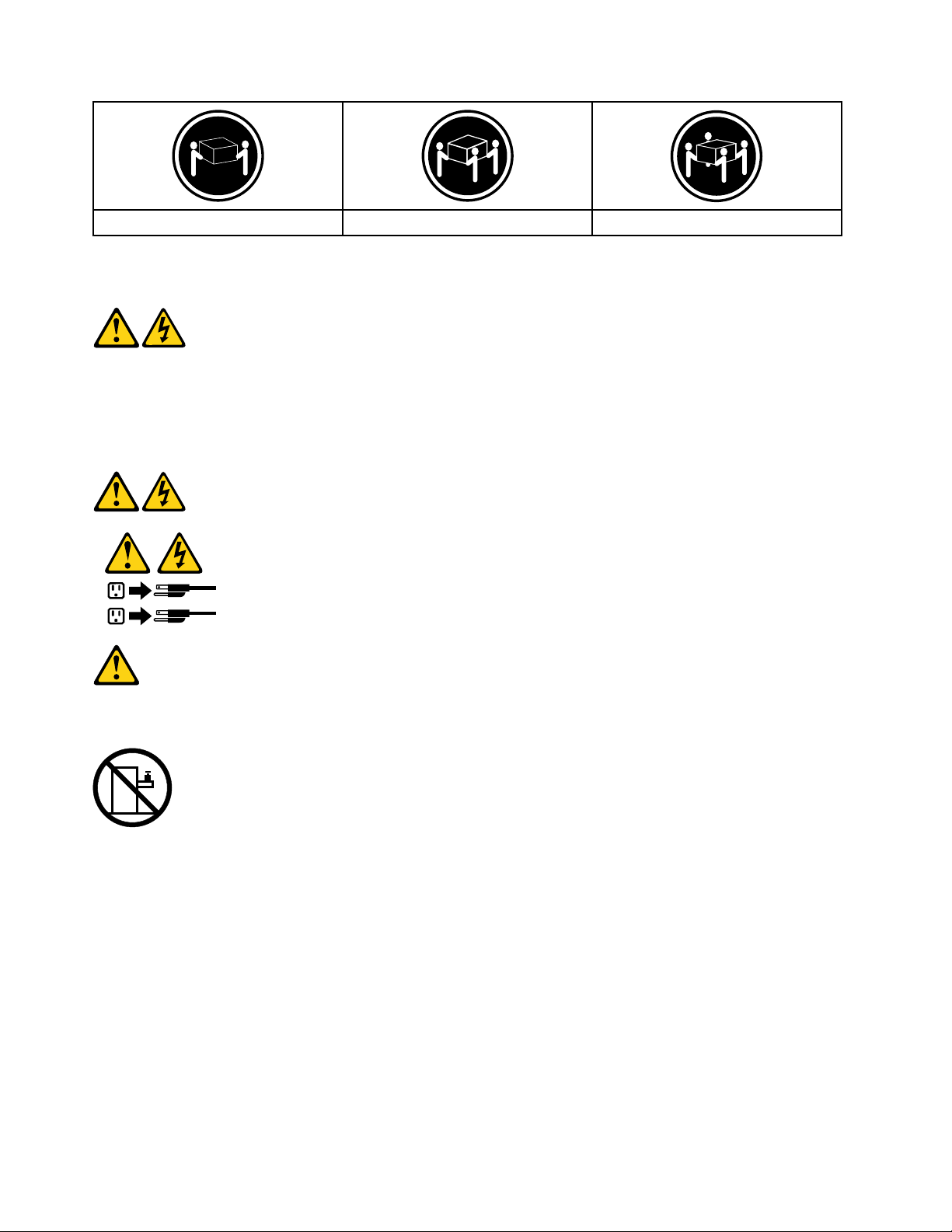
≥18kg(37lbs)≥32kg(70.5lbs)≥55kg(121.2lbs)
1
2
CAUTION:
Usesafepracticeswhenlifting.
CAUTION:
Thepowercontrolbuttononthedeviceandthepowerswitchonthepowersupplydonotturnoff
theelectricalcurrentsuppliedtothedevice.Thedevicealsomighthavemorethanonepower
cord.Toremoveallelectricalcurrentfromthedevice,ensurethatallpowercordsaredisconnected
fromthepowersource.
CAUTION:
Donotplaceanyobjectweighingmorethan82kg(180lbs.)ontopofrack-mounteddevices.
8ideacentreAll-In-One910HardwareMaintenanceManual
Page 15

Chapter3.Generalinformation
Thischapterprovidesgeneralinformationthatappliestoallcomputermodelscoveredbythismanual.
Specifications
Thissectionliststhephysicalspecificationsforyourcomputer.
Thissectionliststhephysicalspecificationsforyourcomputer.
TypeideacentreAll-In-One910
Thissectionliststhephysicalspecifications.
Environment
Airtemperature:
Operating:10°to35°C
Transit:-20°to55°C
Humidity:
Operating:35%to80%
Transit:20%to90%(40°C)
Altitude:86KPato106KPa
Electricalinput:
Inputvoltage:90V-264V(AC)
Inputfrequency:47Hz-63Hz
©CopyrightLenovo2016
9
Page 16

10ideacentreAll-In-One910HardwareMaintenanceManual
Page 17

Chapter4.GeneralCheckout
Attention:Thedrivesinthecomputeryouareservicingmighthavebeenrearrangedorthedrivestartup
sequencemayhavebeenchanged.Beextremelycarefulduringwriteoperationssuchascopying,saving,or
formatting.Dataorprogramscanbeoverwrittenifyouselectanincorrectdrive.
Generalerrormessagesappearifaproblemorconflictisfoundbyanapplication,theoperatingsystem,or
both.Foranexplanationofthesemessages,refertotheinformationsuppliedwiththatsoftwarepackage.
Usethefollowingproceduretohelpdeterminethecauseoftheproblem:
1.Power-offthecomputerandallexternaldevices.
2.Checkallcablesandpowercords.
3.Setalldisplaycontrolstothemiddleposition.
4.Power-onallexternaldevices.
5.Power-onthecomputer.
•Lookfordisplayederrorcodes.
•Lookforreadableinstructionsoramainmenuonthedisplay.
Ifyoudidnotreceivethecorrectresponse,proceedtostep6.
Ifyoudidreceivethecorrectresponse,proceedtostep7.
6.Ifoneofthefollowinghappens,followtheinstructiongiven:
•IfthecomputerdisplaysaPOSTerror,goto“POSTerrorcodes” .
•Ifthecomputerhangsandnoerrorisdisplayed,continueatstep7.
7.Iftheteststopsandyoucannotcontinue,replacethelastdevicetested.
©CopyrightLenovo2016
11
Page 18

12ideacentreAll-In-One910HardwareMaintenanceManual
Page 19

Chapter5.UsingtheSetupUtility
TheSetupUtilityprogramisusedtoviewandchangetheconfigurationsettingsofyourcomputer,regardless
ofwhichoperatingsystemyouareusing.However,theoperatingsystemsettingsmightoverrideanysimilar
settingsintheSetupUtilityprogram.
StartingtheLenovoBIOSSetupUtilityprogram
TostarttheLenovoBIOSSetupUtilityprogram,dothefollowing:
1.Ifyourcomputerisalreadyonwhenyoustartthisprocedure,shutdowntheoperatingsystemand
turnoffthecomputer.
2.PressandholdtheF1keythenturnonthecomputer.WhentheLenovoBIOSSetupUtilityprogramis
displayed,releasetheF1key.
Note:IfaPower-OnPasswordoranAdministratorPasswordhasbeenset,theSetupUtilityprogrammenu
willnotbedisplayeduntilyoutypeyourpassword.Formoreinformation,see“Usingpasswords.”
Viewingandchangingsettings
SystemconfigurationoptionsarelistedintheLenovoBIOSSetupUtilityprogrammenu.Tovieworchange
settings,see“StartingtheSetupUtilityprogram. ”
YoumustusethekeyboardwhenusingtheLenovoBIOSSetupUtilitymenu.Thekeysusedtoperform
varioustasksaredisplayedonthebottomofeachscreen.
Usingpasswords
YoucanusetheLenovoBIOSSetupUtilityprogramtosetpasswordstopreventunauthorizedpersons
fromgainingaccesstoyourcomputeranddata.See“StartingtheSetupUtilityprogram.”Thefollowing
typesofpasswordsareavailable:
•AdministratorPassword
•Power-OnPassword
Youdonothavetosetanypasswordstouseyourcomputer.However,ifyoudecidetosetpasswords,read
thefollowingsections.
Passwordconsiderations
Apasswordcanbeanycombinationoflettersandnumbersupto16characters(a-zand0-9).Forsecurity
reasons,itisagoodideatouseastrongpasswordthatcannotbeeasilycompromised.Wesuggestthat
passwordsshouldfollowtheserules:
•Forastrongpassword,use7-16charactersandamixoflettersandnumbers.
•Donotuseyournameoryourusername.
•Donotuseacommonwordoracommonname.
•Usesomethingsignificantlydifferentfromyourpreviouspassword.
Attention:AdministratorandPower-Onpasswordsarenotcasesensitive.
©CopyrightLenovo2016
13
Page 20

AdministratorPassword
SettinganAdministratorPassworddetersunauthorizedpersonsfromchangingconfigurationsettings.You
mightwanttosetanAdministratorPasswordifyouareresponsibleformaintainingthesettingsofseveral
computers.
AfteryousetanAdministratorPassword,apasswordpromptisdisplayedeverytimeyouaccesstheLenovo
BIOSSetupUtilityprogram.
IfboththeAdministratorandPower-OnPasswordareset,youcantypeeitherpassword.However,youmust
useyourAdministratorPasswordtochangeanyconfigurationsettings.
Setting,changing,ordeletinganAdministratorpassword
TosetanAdministratorPassword,dothefollowing:
Note:Apasswordcanbeanycombinationoflettersandnumbersupto16characters(a-zand0-9).For
moreinformation,see“Passwordconsiderations”onpage13.
1.StarttheLenovoBIOSSetupUtilityprogram(see“StartingtheLenovoBIOSSetupUtilityprogram”on
page13).
2.FromtheSecuritymenu,selectSetAdministratorPasswordandpresstheEnterkey.
3.Thepassworddialogboxwillbedisplayed.TypethepasswordthenpresstheEnterkey.
4.Re-typethepasswordtoconfirm,thenpresstheEnterkey.Ifyoutypedthepasswordcorrectly,
thepasswordwillbeinstalled.
TochangeanAdministratorPassword,dothefollowing:
1.StarttheLenovoBIOSSetupUtilityprogram(see“StartingtheLenovoBIOSSetupUtilityprogram”on
page13).
2.FromtheSecuritymenu,selectSetAdministratorPasswordandpresstheEnterkey.
3.Thepassworddialogboxwillbedisplayed.T ypethecurrentpasswordthenpresstheEnterkey.
4.T ypethenewpassword,thenpresstheEnterkey.Re-typethepasswordtoconfirmthenewpassword.
Ifyoutypedthenewpasswordcorrectly,thenewpasswordwillbeinstalled.ASetupNoticedconfirming
thatchangeshavebeensavedwillbedisplayed.
TodeleteapreviouslysetAdministratorPassword,dothefollowing:
1.FromtheSecuritymenu,selectSetAdministratorPasswordandpresstheEnterkey.
2.Thepassworddialogboxwillbedisplayed.T ypethecurrentpasswordandpresstheEnterkey.
3.T odeleteanAdministratorPassword,leaveeachnewpasswordlineitemblank,thenpresstheEnter
key.ASetupNoticeconfirmingthatchangeshavebeensavedwillbedisplayed.
4.ReturntotheLenovoBIOSSetupUtilityprogrammenuandselecttheExitoption.
5.SelectSavechangesandExitfromthemenu.
Power-OnPassword
WhenaPower-OnPasswordisset,youcannotstarttheLenovoBIOSSetupUtilityprogramuntilavalid
passwordistypedfromthekeyboard.
Setting,changing,ordeletingaPower-OnPassword
Note:Apasswordcanbeanycombinationoflettersandnumbersupto16characters(a-zand0-9).
14ideacentreAll-In-One910HardwareMaintenanceManual
Page 21

TosetaPower-OnPassword,dothefollowing:
1.StarttheLenovoBIOSSetupUtilityprogram(See”StartingtheLenovoBIOSSetupUtilityprogram”on
page13.)
2.FromtheSecuritymenu,selectSetPower-OnPasswordandpresstheEnterkey.
3.Thepassworddialogboxwillbedisplayed.Typethepassword,thenpresstheEnterkey.
4.Re-typethepasswordtoconfirm.Ifyoutypedthepasswordcorrectly,thepasswordwillbeinstalled.
TochangeaPower-OnPassword,dothefollowing:
1.StarttheLenovoBIOSSetupUtilityprogram(See”StartingtheLenovoBIOSSetupUtilityprogram”on
page13.)
2.FromtheSecuritymenu,selectSetPower-OnPasswordandpresstheEnterkey.
3.Thepassworddialogboxwillbedisplayed.T ypethecurrentpasswordthenpresstheEnterkey.
4.T ypethenewpassword,thenpresstheEnterkey.Re-typethepasswordtoconfirmthenewpassword.
Ifyoutypedthenewpasswordcorrectly,thenewpasswordwillbeinstalled.ASetupNoticedconfirming
thatchangeshavebeensavedwillbedisplayed.
TodeleteapreviouslysetPower-OnPassword,dothefollowing:
1.FromtheSecuritymenu,selectSetPower-OnPasswordandpresstheEnterkey.
2.Thepassworddialogboxwillbedisplayed.T ypethecurrentpasswordandpresstheEnterkey.
3.T odeletethePower-OnPassword,leaveeachnewpasswordlineitemblank,thenpressEnter.ASetup
Noticeconfirmingthatchangeshavebeensavedwillbedisplayed.
4.ReturntotheLenovoBIOSSetupUtilityprogrammenuandselecttheExitoption.
5.SelectSavechangesandExitfromthemenu.
Enablingordisablingadevice
TheDevicesoptionsisusedtoenableordisableuseraccesstothefollowingdevices:
USBFunctionsSelectwhethertoenableordisableUSB(UniversalSerial
Bus)functions.Ifthefunctionsaredisabled,noUSB
devicescanbeused.
SATAMode
OnboardAudioControllerSelectwhethertoenableordisabletheOnboard
OnboardEthernetControllerorLANBootAgentSelectwhethertoenableordisabletheOnboardEthernet
Toenableordisableadevice,dothefollowing:
1.StarttheSetupUtilityprogram(see“StartingtheSetupUtilityprogram”onpage13).
2.FromtheSetupUtilityprogrammenu,selectDevices.
3.Selectanoptionasfollows:
WhenthisfeatureissettoDisabled,alldevices
connectedtotheSATAconnectors(e.g.harddiskdrives
ortheopticaldiskdrive)aredisabledandcannotbe
accessed.
AudioController.WhenthisfeatureissettoDisabled
alldevicesconnectedtotheaudioconnectors(e.g.
headphonesoramicrophone)aredisabledandcannot
beused.
Controller,orselectwhethertoenableordisableload
onboardPXE(PrebootExecutionEnvironment).
SelectUSBSetup,presstheEnterkey,thenselectUSBFunctions.
Chapter5.UsingtheSetupUtility15
Page 22

SelectA TADeviceSetup,presstheEnterkey,thenselectSA T AMode.
SelectAudioSetup,presstheEnterkey,thenselectOnboardAudioController.
SelectNetworkSetup,presstheEnterkey,thenselectOnboardEthernetSupportorLANBoot
Agent.
4.SelectDisabledorEnabledandpresstheEnterkey.
5.ReturntotheLenovoBIOSSetupUtilityprogrammenuandselecttheExitoption.
6.SelectSavechangesandExitfromthemenu.
Notes:
a.Ifyoudonotwanttosavethesettings,selectDiscardchangesandExitfromthemenu.
b.SelectIDE/AHCIMode:DevicedriversupportisrequiredforACHI.Dependingonhowtheharddisk
imagewasinstalled,changingthissettingmaypreventthesystemfrombooting.
Selectingastartupdevice
IfyourcomputerdoesnotbootfromadevicesuchastheCD/DVD-ROMdrivediskorharddiskasexpected,
followoneoftheproceduresbelow.
Selectingatemporarystartupdevice
Usethisproceduretostartupfromanybootdevice.
Note:NotallCDs,DVDsorharddiskdrivesarebootable.
1.T urnoffyourcomputer.
2.PressandholdtheF12keythenturnonthecomputer.WhentheStartupDeviceMenuappears,
releasetheF12key.
Note:IftheStartupDeviceMenudoesnotdisplayusingthesesteps,repeatedlypressandreleasethe
F12keyratherthankeepingitpressedwhenturningonthecomputer.
3.Use↑and↓arrowstoselectthedesiredstartupdevicefromtheStartupDeviceMenuandpress
theEnterkeytobegin.
Note:SelectingastartupdevicefromtheStartupDeviceMenudoesnotpermanentlychangethe
startupsequence.
Selectingorchangingthestartupdevicesequence
Tovieworpermanentlychangetheconfiguredstartupdevicesequence,dothefollowing:
1.StarttheLenovoBIOSSetupUtilityprogram(see“StartingtheLenovoBIOSSetupUtilityprogram”on
page13).
2.FromtheLenovoBIOSSetupUtilityprogrammainmenu,selecttheStartupoption.
3.PresstheEnterkey,andselectthedevicesforthePrimaryBootSequence.Readtheinformation
displayedontherightsideofthescreen.
4.Use↑and↓arrowstoselectadevice.Usethe<+>or<->keystomoveadeviceupordown.Usethe
<×>keytoexcludethedevicefromorincludethedeviceinthebootsequence.
5.ReturntotheLenovoBIOSSetupUtilityprogrammenuandselecttheExitoption.
6.SelectSavechangesandExitfromthemenu.
Notes:
16ideacentreAll-In-One910HardwareMaintenanceManual
Page 23

a.Ifyoudonotwanttosavethesettings,selectDiscardchangesandExitfromthemenu.
b.Ifyouhavechangedthesesettingsandwanttoreturntothedefaultsettings,selectLoadOptimal
Defaultsfromthemenu.
ExitingtheLenovoBIOSSetupUtilityprogram
Afteryoufinishviewingorchangingsettings,presstheEsckeytoreturntotheLenovoBIOSSetupUtility
programmainmenu.Y oumighthavetopresstheEsckeyseveraltimes.Dooneofthefollowing:
•Ifyouwanttosavethenewsettings,selectSavechangesandExitfromthemenu.WhentheSave&
resetwindowshows,selecttheY esbutton,andthenpresstheEnterkeytoexittheLenovoBIOS
SetupUtilityprogram.
•Ifyoudonotwanttosavethesettings,selectDiscardchangesandExitfromthemenu.Whenthe
ResetWithoutSavingwindowshows,selecttheY esbutton,andthenpresstheEnterkeytoexitthe
LenovoBIOSSetupUtilityprogram.
Chapter5.UsingtheSetupUtility17
Page 24

18ideacentreAll-In-One910HardwareMaintenanceManual
Page 25

Chapter6.Symptom-to-FRUIndex
TheSymptom-to-FRUindexlistserrorsymptomsandpossiblecauses.Themostlikelycauseislistedfirst.
AlwaysbeginwithChapter4,“GeneralCheckout, ”onpage11.Thisindexcanalsobeusedtohelpyou
decidewhichFRUstohaveavailablewhenservicingacomputer.Ifyouareunabletocorrecttheproblem
usingthisindex,goto“Undeterminedproblems”onpage20.
Notes:
•Ifyouhavebothanerrormessageandanincorrectaudioresponse,diagnosetheerrormessagefirst.
•Ifyoucannotrunthediagnostictestsoryougetadiagnosticerrorcodewhenrunningatestbutdid
receiveaPOSTerrormessage,diagnosethePOSTerrormessagefirst.
•Ifyoudidnotreceiveanyerrormessagelookforadescriptionofyourerrorsymptomsinthefirstpartof
thisindex.
Harddiskdrivebooterror
Aharddiskdrivebooterrorcanbecausedbythefollowing.
Error
Thestartupdriveisnotincludedinthebootsequence
configuration.
Nooperatingsystemisinstalledonthebootdrive.Installanoperatingsystemonthebootdrive.
Thebootsectoronthestartupdriveiscorrupted.
Thedriveisdefective.
FRU/Action
Checktheconfigurationandensurethestartupdriveis
inthebootsequence.
Thedrivemustbeformatted.Dothefollowing:
1.Attempttobackupthedataonthefailingharddisk
drive.
2.Usetheoperatingsystemtoformattheharddisk
drive.
Replacetheharddiskdrive.
PowerSupplyProblems
Followtheseproceduresifyoususpectthereisapowersupplyproblem.
Check/VerifyFRU/Action
Checkthatthefollowingareproperlyinstalled:
•PowerCord
•On/OffSwitchconnector
•SystemBoardPowerSupplyconnectors
•Microprocessorconnections
Checkthepowercord.PowerCord
Checkthepower-onswitch.Power-onSwitch
Reseatconnectors
©CopyrightLenovo2016
19
Page 26

POSTerrorcodes
Eachtimeyouturnthecomputeron,itperformsaseriesofteststocheckthatthesystemisoperating
correctlyandthatcertainoptionsareset.ThisseriesoftestsiscalledthePower-OnSelf- T est,orPOST.
POSTdoesthefollowing:
•Checkssomebasicmotherboardoperations
•Checksthatthememoryisworkingcorrectly
•Startsvideooperations
•Verifiesthatthebootdriveisworking
POSTErrorMessageDescription/Action
Keyboarderror
RebootandSelectproperBootdeviceorInsertBoot
MediainselectedBootdevice
Cannotinitializethekeyboard.Makesurethekeyboard
isproperlyconnectedtothecomputerandthatnokeys
areheldpressedduringPOST.T opurposelyconfigure
thecomputerwithoutakeyboard,selectKeyboardless
operationinStartupandsettheoptiontoEnabled.The
BIOSthenignoresthemissingkeyboardduringPOST.
TheBIOSwasunabletofindasuitablebootdevice.Make
surethebootdriveisproperlyconnectedtothecomputer.
Makesureyouhavebootablemediainthebootdevice.
Undeterminedproblems
1.Power-offthecomputer.
2.Removeordisconnectthefollowingcomponents(ifconnectedorinstalled)oneatatime.
a.Externaldevices(modem,printer,ormouse)
b.Extendedvideomemory
c.ExternalCache
d.ExternalCacheRAM
e.Harddiskdrive
f.Diskdrive
3.Power-onthecomputertore-testthesystem.
4.Repeatsteps1through3untilyoufindthefailingdeviceorcomponent.
Ifalldevicesandcomponentshavebeenremovedandtheproblemcontinues,replacethesystemboard.
20ideacentreAll-In-One910HardwareMaintenanceManual
Page 27

Chapter7.Locatingconnectors,controlsandcomponents
Thissectionprovidesillustrationstohelplocatethevariousconnectors,controlsandcomponentsofthe
computer.
Fontview
Thefollowingillustrationshowsthelocationofcontrolsandcomponentsonthefrontofthecomputer.
Attention:Becarefulnottoblockanyairventsonthecomputer.Blockedairventscancauseoverheating.
1.Built-inmicrophone
2.Built-incamera4.PowerLEDindicator
©CopyrightLenovo2016
3.CameraLEDindicator
21
Page 28

Leftandrightview
Thefollowingillustrationshowsthelocationofconnectors,controlsandcomponentsontheleftandright
sideofthecomputer.
1.HDMIin/outswitch
2.HDMIin/outconnector
3.USB3.0connector(3)
4.Memorycardreader
5.Powerbutton
22ideacentreAll-In-One910HardwareMaintenanceManual
Page 29

Rearview
Thefollowingillustrationshowsthelocationofconnectorsandcomponentsontherearofthecomputer.
1.Powerconnector
2.Ethernetconnector5.Airvents
3.USB2.0connector
4.Comboaudiojack
1
1.Comboaudiojack:Usedtoconnectheadsets.
Chapter7.Locatingconnectors,controlsandcomponents23
Page 30

Hardwarecomponents
1
2
3
13
14
15
16
17
18
20
21
19
4
5
6
7
8
9
10
12
11
Thefollowingillustrationshowsthecomponentsthatmakeupyourcomputer.
1.Computerstand12.Speakers(2)
2.Camerawithbracket
3.Microphonemodule14.Memory
4.Rearcoverdeco
5.Rearcover
13.Basetopcover
15.Solidstatedisk
16.HeatSink
6.Scalarboardshield17.Systemfan
18.Motherboard
20.Harddiskdrive
7.Scalarboard
8.Wi-Ficard19.Basebottomcover
9.Subwoofer(2)
10.LEDPanel21.Harddiskdrivedoor
11.Powerswitchboard
24ideacentreAll-In-One910HardwareMaintenanceManual
Page 31

Identifyingpartsonthemotherboard
2
3
4
6 7 8
1
5
9
10
11
Themotherboard(sometimescalledtheplanarorsystemboard)isthemaincircuitboardinyourcomputer.
Itprovidesbasiccomputingfunctionsandsupportsavarietyofdevicesthatarefactory-installedorthat
youcaninstalllater.Thefollowingillustrationshowsthelocationofconnectorsandcomponentsonthe
frontofthemotherboard.
1.8-pinpowerconnector(DCIN1)7.ClearCMOSSwitch
2.Microprocessor(CPU1)8.M.2connector(SATASSD1)
3.Systemfanconnector
4.MemorySlot1(DIMM1)10.Scalar1connector
5.Batterypowerconnector
6.MEdisableswitch
9.HDMIswitch
11.Scalar2connector
Chapter7.Locatingconnectors,controlsandcomponents25
Page 32

IdentifyingpartsonthebackoftheLEDpanel
12
ThefollowingillustrationshowsthecomponentsandcontrolsonthebackofLEDpanel.
12.SA T A1connector(HDD1)
26ideacentreAll-In-One910HardwareMaintenanceManual
Page 33

Chapter8.Replacinghardware
Attention:Donotremovethecomputercoverorattemptanyrepairbeforereadingthe“Importantsafetyinformation”
intheSafetyandWarrantyGuidethatwasincludedwithyourcomputer.ToobtaincopiesoftheSafetyandWarranty
Guide,gototheSupportWebsiteat:http://consumersupport.lenovo.com.
Note:UseonlypartsprovidedbyLenovo.
Generalinformation
Pre-disassemblyinstructions
Beforestartingthedisassemblyprocedure,makesurethatyoudothefollowing:
1.T urnoffthepowertothesystemandallperipherals.
2.Unplugallpowerandsignalcablesfromthecomputer.
3.Placethesystemonaflat,stablesurface.
©CopyrightLenovo2016
27
Page 34

Replacingthekeyboardandmouse
Note:YourkeyboardwillbeconnectedtoaUSBconnectorateithersideorattherearofthecomputer.
Toreplacethekeyboard:
Step1.Removeanymedia(disks,CDs,ormemorycards)fromthedrives,shutdownthecomputer,and
turnoffallattacheddevices.
Step2.Unplugallpowercordsfromelectricaloutlets.
Step3.Locatetheconnectorforthekeyboard.Referto“Sideviewofthecomputer”and“Rearviewof
thecomputer”.
Step4.Disconnectthedefectivekeyboardcablefromthecomputerandconnectthenewkeyboardcable
tothesameconnector.
Step5.Themousecanbereplacedusingthesamemethod.
Replacingtheadapter
Attention:Turnoffthecomputerandwait3to5minutestoletitcooldownbeforeremovingthecover.
Step1.Removeanymedia(disks,CDs,ormemorycards)fromthedrives,shutdowntheoperating
system,andturnoffthecomputerandallattacheddevices.
Step2.Disconnecttheadapterfromtheconnectoronthecomputer,thenunplugtheadapterfrom
electricaloutlet.
28ideacentreAll-In-One910HardwareMaintenanceManual
Page 35

Step3.Connectthenewadapterasshown.
Replacingtheharddiskdrive
Attention:Turnoffthecomputerandwait3to5minutestoletitcooldownbeforeremovingthecover.
Toreplacetheharddiskdrive
Step1.Removeanymedia(disks,CDs,DVDsormemorycards)fromthedrives,shutdowntheoperating
system,andturnoffthecomputerandallattacheddevices.
Step2.Unplugallpowercordsfromelectricaloutlets.
Step3.Disconnectallcablesattachedtothecomputer.Thisincludespowercords,input/output(I/O)
cables,andanyothercablesthatareconnectedtothecomputer.Referto“Leftandrightview”
and“Rearview”forhelpwithlocatingthevariousconnectors.
Step4.Removeonescrewthatsecuretheharddiskdrivecovertothebasestanda,andthenremove
theHDDcoverb.
Step5.Removethe4screwsthatsecuretheharddiskdrivebrackettothebasestandc.
Step6.Disconnectthedataandpowercablefromtheharddiskdrived
Step7.Removethe4screwsthatsecuretheharddiskdrivetothebrackete.Slidetheharddiskdrive
outofthebayasshownf.
Chapter8.Replacinghardware29
Page 36

Step8.Installthenewharddiskdriveasfollows:
a.Sidetheharddiskdriveintotheharddiskdrivebayandsecurethemwith4screws.
b.Connectthedataandpowercabletothenewharddisk.
c.Securethenewharddiskdrivebaytothebasestandwiththe4screws.
Step9.Reattachtheharddiskdrivecoverandsecureitwiththescrews.
Removingtherearcover
Note:Turnoffthecomputerandwait3to5minutestoletitcooldownbeforeremovingthecover.
Toremovetherearcover
Step1.Removeanymedia(disks,CDs,DVDs,ormemorycards)fromthedrives,shutdowntheoperating
system,andturnoffthecomputerandallattacheddevices.
Step2.Unplugallpowercordsfromelectricaloutlets.
30ideacentreAll-In-One910HardwareMaintenanceManual
Page 37

Step3.Disconnectallcablesattachedtothecomputer.Thisincludespowercords,input/output(I/O)
1
2
cables,andanyothercablesthatareconnectedtothecomputer.Referto“Leftandrightview”
and“Rearview”forhelpwithlocatingthevariousconnectors.
Step4.Removethebasecover.Referto“Removingthebasecover” .
Step5.Raisethehinge1andslidethereardecooutasshown.2
Step6.Workingaroundtheedgeinananti-clockwisedirection,useyourfingerstopriseuptherearcover.
Therearcoverispinnedintoplace,useshort,sharpmovementstopriseitup.
Step7.Pressdownthehingeandslideouttherearcover.
Step8.T oreattachtherearcover:
a.Raisethehinge,lineuptherearcoverwiththeLEDpanelandslideitbackintoposition.
b.PresstheedgeofrearcovertolockthecovertotheLEDpanelwiththepins.
c.Slidethereardecobackintoposition.
Removingthesubwooferspeakers
Note:Turnoffthecomputerandwait3to5minutestoletitcooldownbeforeremovingthecover.
Toremovetherearcover
Step1.Removeanymedia(disks,CDs,DVDs,ormemorycards)fromthedrives,shutdowntheoperating
system,andturnoffthecomputerandallattacheddevices.
Step2.Unplugallpowercordsfromelectricaloutlets.
Step3.Disconnectallcablesattachedtothecomputer.Thisincludespowercords,input/output(I/O)
cables,andanyothercablesthatareconnectedtothecomputer.Referto“Leftandrightview”
and“Rearview”forhelpwithlocatingthevariousconnectors.
Chapter8.Replacinghardware31
Page 38

Step4.Removetherearcover.Referto“Removingtherearcover”.
Step5.Removethe12screwsthatsecurethesubwooferspeakerstotheLEDPanelbracket,thenliftup
thetwosubwooferspeakerstoremovethem.
Step6.T oinstallnewsubwooferspeakers:
a.Placethenewsubwooferspeakersintoposition,thensecurethemwith12screws.
b.PresstheedgeofrearcovertolockthecovertotheLEDpanelwiththepins.
c.Slidethereardecobackintoposition.
Removingthespeakerssystem
Note:Turnoffthecomputerandwait3to5minutestoletitcooldownbeforeremovingthecover.
Toremovetherearcover
Step1.Removeanymedia(disks,CDs,DVDs,ormemorycards)fromthedrives,shutdowntheoperating
system,andturnoffthecomputerandallattacheddevices.
Step2.Unplugallpowercordsfromelectricaloutlets.
Step3.Disconnectallcablesattachedtothecomputer.Thisincludespowercords,input/output(I/O)
cables,andanyothercablesthatareconnectedtothecomputer.Referto“Leftandrightview”
and“Rearview”forhelpwithlocatingthevariousconnectors.
Step4.Removetherearcover.Referto“Removingtherearcover”.
Step5.Disconnectthespeakercablefromtheconnectorsonthescalarboard,andthenliftupthetwo
speakerstoremovethem.
32ideacentreAll-In-One910HardwareMaintenanceManual
Page 39

Step6.T oinstallnewspeakersystem:
a.Placethenewspeakersintoposition.
b.Connectthenewspeakercablestotheconnectoronthescalarboard.
c.PresstheedgeofrearcovertolockthecovertotheLEDpanelwiththepins.
d.Slidethereardecobackintoposition.
ReplacingtheWi-Ficard
Note:Turnoffthecomputerandwait3to5minutestoletitcooldownbeforeremovingthecover.
Note:Itmaybehelpfultoplacethecomputerface-downonasoftflatsurfaceforthisprocedure.Lenovo
recommendsthatyouuseablanket,towel,orothersoftclothtoprotectthecomputerscreenfromscratches
orotherdamage.
ToreplacetheWi-Ficard:
Step1.Removeanymedia(disks,CDs,DVDs,ormemorycards)fromthedrives,shutdowntheoperating
system,andturnoffthecomputerandallattacheddevices.
Step2.Unplugallpowercordsfromelectricaloutlets.
Step3.Disconnectallcablesattachedtothecomputer.Thisincludespowercords,input/output(I/O)
cables,andanyothercablesthatareconnectedtothecomputer.Referto“Leftandrightview”
and“Rearview”forhelpwithlocatingthevariousconnectors.
Step4.Removetherearcover.Referto“Removingtherearcover”.
Chapter8.Replacinghardware33
Page 40

Step5.DisconnecttheantennacablesfromtheWi-Ficard.
Step6.RemovethescrewthatsecurestheWi-Ficardtothemotherboard.
Step7.LiftuptheWi-Ficardtoremoveitfromthesocket.
Step8.T oinstallthenewWi-Ficard:
a.InsertthenotchedendoftheWi-Ficardintothecardportonthescalarboard.
b.SecurenewtheWi-Ficardtothescalarboard.withthescrew.
c.ConnecttheantennacablestothenewWi-Ficard.
d.PresstheedgeofrearcovertolockthecovertotheLEDpanelwiththepins.
e.Slidethereardecobackintoposition.
Replacingthescalarboard
Note:Turnoffthecomputerandwait3to5minutestoletitcooldownbeforeremovingthecover.
Toreplacethescalarboard
Step1.Removeanymedia(disks,CDs,DVDs,ormemorycards)fromthedrives,shutdowntheoperating
system,andturnoffthecomputerandallattacheddevices.
Step2.Unplugallpowercordsfromelectricaloutlets.
Step3.Disconnectallcablesattachedtothecomputer.Thisincludespowercords,input/output(I/O)
cables,andanyothercablesthatareconnectedtothecomputer.Referto“Leftandrightview”
and“Rearview”forhelpwithlocatingthevariousconnectors.
Step4.Removetherearcover.Referto“Removingtherearcover”.
Step5.Removethe4screwsthatsecurethescalarboardtotheLEDpanelbracket.
34ideacentreAll-In-One910HardwareMaintenanceManual
Page 41

Step6.Removethescalarshieldingandsetitaside.
Step7.Disconnectallthecablesfromthescalarboard.
Step8.Removethe4screwsthatsecurethescalarboardtothemiddleframeandliftituptoremoveit.
Step9.T oinstallthenewscalarboard:
a.Lineuptheholesonthenewscalarboardwiththemountingholesonthemiddleframeand
secureitwiththe4screws.
b.Connectallthecablestothenewscalarboard.
c.Reattachthescalarshieldingtothemiddleframewiththe4screws.
Step10.ReattachtherearcovertotheLEDpanel.
Step11.PresstheedgeofrearcovertolockthecovertotheLEDpanelwiththepins.
Step12.Slidethereardecobackintoposition.
Replacingthecamerawithbracket
Note:Turnoffthecomputerandwait3to5minutestoletitcooldownbeforeremovingthecover.
Chapter8.Replacinghardware35
Page 42

Note:Itmaybehelpfultoplacethecomputerface-downonasoftflatsurfaceforthisprocedure.Lenovo
recommendsthatyouuseablanket,towel,orothersoftclothtoprotectthecomputerscreenfromscratches
orotherdamage.
Toreplacethecamera:
Step1.Removeanymedia(disks,CDs,DVDs,ormemorycards)fromthedrives,shutdowntheoperating
system,andturnoffthecomputerandallattacheddevices.
Step2.Unplugallpowercordsfromelectricaloutlets.
Step3.Disconnectallcablesattachedtothecomputer.Thisincludespowercords,input/output(I/O)
cables,andanyothercablesthatareconnectedtothecomputer.Referto“Leftandrightview”
and“Rearview”forhelpwithlocatingthevariousconnectors.
Step4.Removetherearcover.Referto“Removingtherearcover”.
Step5.Removethetwoscrewsthatsecurecamerawithbrackettothefrontbezel.
Step6.Disconnectthecameradatacablefromtheconnectoronthecamera.
Step7.T oinstallthenewcamera:
a.Connectthedatacabletothenewcamera.
b.Placethenewcamerawithbracketintoposition,securethecamerabrackettothefront
bezelwiththetwoscrews.
Step8.Reattachtherearcover.
Replacingthepowerswitchboard
Note:Turnoffthecomputerandwait3to5minutestoletitcooldownbeforeremovingthecover.
36ideacentreAll-In-One910HardwareMaintenanceManual
Page 43

Note:Itmaybehelpfultoplacethecomputerface-downonasoftflatsurfaceforthisprocedure.Lenovo
2
1
recommendsthatyouuseablanket,towel,orothersoftclothtoprotectthecomputerscreenfromscratches
orotherdamage.
Toreplacethepowerswitchboard
Step1.Removeanymedia(disks,CDs,DVDs,ormemorycards)fromthedrives,shutdowntheoperating
system,andturnoffthecomputerandallattacheddevices.
Step2.Unplugallpowercordsfromelectricaloutlets.
Step3.Disconnectallcablesattachedtothecomputer.Thisincludespowercords,input/output(I/O)
cables,andanyothercablesthatareconnectedtothecomputer.Referto“Leftandrightview”
and“Rearview”forhelpwithlocatingthevariousconnectors.
Step4.Removetherearcover.Referto“Removingtherearcover”.
Step5.Disconnectthedatacablefromthepowerswitchboard1.
Step6.Pushthelockingpinoutwardtoreleasethepowerswitchboard2,thenliftupthepowerswitch
boardtoremoveit.
Step7.T oinstallthepowerswitchboard:
a.Connectthecabletothenewpowerswitchboard.
b.Attachthenewpowerswitchboardtothechassis.
c.Securethepowerswitchboardwiththelockingpins.
Step8.Reattachtherearcover.
Replacingthemicrophone
Note:Turnoffthecomputerandwait3to5minutestoletitcooldownbeforeremovingthecover.
Chapter8.Replacinghardware37
Page 44

Note:Itmaybehelpfultoplacethecomputerface-downonasoftflatsurfaceforthisprocedure.Lenovo
recommendsthatyouuseablanket,towel,orothersoftclothtoprotectthecomputerscreenfromscratches
orotherdamage.
Toreplacethepowerswitchboard
Step1.Removeanymedia(disks,CDs,DVDs,ormemorycards)fromthedrives,shutdowntheoperating
system,andturnoffthecomputerandallattacheddevices.
Step2.Unplugallpowercordsfromelectricaloutlets.
Step3.Disconnectallcablesattachedtothecomputer.Thisincludespowercords,input/output(I/O)
cables,andanyothercablesthatareconnectedtothecomputer.Referto“Leftandrightview”
and“Rearview”forhelpwithlocatingthevariousconnectors.
Step4.Removetherearcover.Referto“Removingtherearcover”.
Step5.Disconnectthemicrophonedatacablefromtheconnectoronthemicrophone.
Step6.Pushthelockingpinoutwardtoreleasethemicrophone,thenliftupthemicrophonetoremoveit.
Step7.T oinstallthenewmicrophone:
a.Connectthecabletothenewmicrophone.
b.Placethenewmicrophonewithbracketintopositionandsecurethemicrophonewiththe
lockingpins.
Step8.Reattachtherearcover.
Removingthebasecover
Note:Turnoffthecomputerandwait3to5minutestoletitcooldownbeforeremovingthecover.
38ideacentreAll-In-One910HardwareMaintenanceManual
Page 45

Note:Itmaybehelpfultoplacethecomputerface-downonasoftflatsurfaceforthisprocedure.Lenovo
1
2
recommendsthatyouuseablanket,towel,orothersoftclothtoprotectthecomputerscreenfromscratches
orotherdamage.
Toremovethebasecover
Step1.Removeanymedia(disks,CDs,DVDs,ormemorycards)fromthedrives,shutdowntheoperating
system,andturnoffthecomputerandallattacheddevices.
Step2.Unplugallpowercordsfromelectricaloutlets.
Step3.Disconnectallcablesattachedtothecomputer.Thisincludespowercords,input/output(I/O)
cables,andanyothercablesthatareconnectedtothecomputer.Referto“Leftandrightview”
and“Rearview”forhelpwithlocatingthevariousconnectors.
Step4.Placethecomputerface-downonasoftflatsurface,thenremovethe8screwsthatsecurethe
basebottomcovertothebase.
Step5.Returnthecomputertoanuprightposition,thenliftthebasetopcoverupandslideitoutasshown.
Step6.T oreattachthebasecover:
a.Lineupthebasetopcoverwiththebase,slideitbackandsnapitintoposition.
Chapter8.Replacinghardware39
Page 46

b.Placethecomputerface-downonasoftflatsurface,thensecurethebasebottomcoverto
1 1
2
3
thebasewiththe8screws.
Removingthehingefromthestandbasecover
Note:Turnoffthecomputerandwait3to5minutestoletitcooldownbeforeremovingthecover.
Toremovethehingefromthechassis
Step1.Removeanymedia(disks,CDs,DVDs,ormemorycards)fromthedrives,shutdowntheoperating
system,andturnoffthecomputerandallattacheddevices.
Step2.Unplugallpowercordsfromelectricaloutlets.
Step3.Disconnectallcablesattachedtothecomputer.Thisincludespowercords,input/output(I/O)
cables,andanyothercablesthatareconnectedtothecomputer.Referto“Leftandrightview”
and“Rearview”forhelpwithlocatingthevariousconnectors.
Step4.Removethebasecover.Referto“Removingthebasecover” .
Step5.Removethe6screwsthatsecurethehingetothestandbasecover1,anddisconnectthetouch
andLEDpanelcablesfromtheconnectorsonthemotherboard
removeitfromthebasecover.3
2,andthenraisethehingeto
Step6.T oreattachthehingetothestandbasecover:
a.Lineupthehingewiththestandbasebottomcoverandslidethehingeintoposition.
b.ReconnectthetouchandLEDpanelcablestothemotherboard.
c.Securethehingetothebasecoverwiththe6screws.
Step7.Reattachthebasecoverandsecureitwiththescrews.
Replacingthememorymodule
Attention:Turnoffthecomputerandwait3to5minutestoletitcooldownbeforeremovingthecover.
Note:Itmaybehelpfultoplacethecomputerface-downonasoftflatsurfaceforthisprocedure.Lenovo
recommendsthatyouuseablanket,towel,orothersoftclothtoprotectthetouchscreenfromscratches
orotherdamage.
Step1.Removeanymedia(disks,CDs,DVDs,ormemorycards)fromthedrives,shutdowntheoperating
Step2.Unplugallpowercordsfromelectricaloutlets.
40ideacentreAll-In-One910HardwareMaintenanceManual
system,andturnoffthecomputerandallattacheddevices.
Page 47

Step3.Disconnectallcablesattachedtothecomputer.Thisincludespowercords,input/output(I/O)
1 1
2
cables,andanyothercablesthatareconnectedtothecomputer.Referto“Leftandrightview”
and“Rearview”forhelpwithlocatingthevariousconnectors.
Step4.Removethebasecover.Referto“Removingthebasecover” .
Step5.Pushoutthelatchesonbothsidesofthememorysockettoreleasethememorymoduleandgently
pullthememorymoduleupwardtoremoveitfromitssocket.
Step6.T oinstallthenewmemorymodule:
a.Alignthenewmemorymodulewiththememorysocket,theninsertitandpushdownonthe
topedge.Makesurethelatcheslockthememorymoduleinplace.
Step7.ReattachtheEMIcover,rearcover,hinge,footcoverandstandbase.
Replacingthesolidstatedisk
Note:Turnoffthecomputerandwait3to5minutestoletitcooldownbeforeremovingthecover.
Note:Itmaybehelpfultoplacethecomputerface-downonasoftflatsurfaceforthisprocedure.Lenovo
recommendsthatyouuseablanket,towel,orothersoftclothtoprotectthecomputerscreenfromscratches
orotherdamage.
Toreplacethesystemfan
Step1.Removeanymedia(disks,CDs,DVDs,ormemorycards)fromthedrives,shutdowntheoperating
system,andturnoffthecomputerandallattacheddevices.
Step2.Unplugallpowercordsfromelectricaloutlets.
Step3.Disconnectallcablesattachedtothecomputer.Thisincludespowercords,input/output(I/O)
cables,andanyothercablesthatareconnectedtothecomputer.Referto“Leftandrightview”
and“Rearview”forhelpwithlocatingthevariousconnectors.
Chapter8.Replacinghardware41
Page 48

Step4.Removethebasecover.Referto“Removingthebasecover” .
Step5.Removethescrewthatsecurethesolidstatedisktothebasebottomcover.
Step6.Liftupthesolidstatedisktoremoveit.
Step7.T oinstallthenewsolidstatedisk:
a.Insertthenotchedendofthenewsolidstatediskintothecardportonthemotherboard.
b.Securenewthesolidstatedisktothebasebottomcoverwiththescrew.
Step8.Reattachthebasecover.
Replacingtheheat-sink
Note:Turnoffthecomputerandwait3to5minutestoletitcooldownbeforeremovingthecover.
Note:Itmaybehelpfultoplacethecomputerface-downonasoftflatsurfaceforthisprocedure.Lenovo
recommendsthatyouuseablanket,towel,orothersoftclothtoprotectthecomputerscreenfromscratches
orotherdamage.
Toreplacetheheat-sink:
Step1.Removeanymedia(disks,CDs,DVDs,ormemorycards)fromthedrives,shutdowntheoperating
system,andturnoffthecomputerandallattacheddevices.
Step2.Unplugallpowercordsfromelectricaloutlets.
Step3.Disconnectallcablesattachedtothecomputer.Thisincludespowercords,input/output(I/O)
cables,andanyothercablesthatareconnectedtothecomputer.Referto“Leftandrightview”
and“Rearview”forhelpwithlocatingthevariousconnectors.
Step4.Removethebasecover.Referto“Removingthebasecover” .
42ideacentreAll-In-One910HardwareMaintenanceManual
Page 49

Step5.Removethescrewsthatsecuretheheat-sinktothemotherboardandbasebottomcover.
Step6.Slidethenliftuptheheat-sinktoremoveit.
Attention:Placetheheat-sinkupsidedownonaflatsurfacetopreventthermalgreasefromcontaminating
othercomponents.
Attention:UseanalcoholpadtowipethethermalgreaseofftheCPU.
Step7.T oinstallthenewheat-sink:
a.Lineupthenewheat-sinkwithmountingholesonthemotherboard,thenplaceitintoposition.
b.Followthenumbersprintedonthenewheat-sinktosecureitinorderusingthescrews.
Step8.Reattachthebasecover.
Replacingthesystemfan
Note:Turnoffthecomputerandwait3to5minutestoletitcooldownbeforeremovingthecover.
Note:Itmaybehelpfultoplacethecomputerface-downonasoftflatsurfaceforthisprocedure.Lenovo
recommendsthatyouuseablanket,towel,orothersoftclothtoprotectthecomputerscreenfromscratches
orotherdamage.
Toreplacethesystemfan
Step1.Removeanymedia(disks,CDs,DVDs,ormemorycards)fromthedrives,shutdowntheoperating
system,andturnoffthecomputerandallattacheddevices.
Step2.Unplugallpowercordsfromelectricaloutlets.
Chapter8.Replacinghardware43
Page 50

Step3.Disconnectallcablesattachedtothecomputer.Thisincludespowercords,input/output(I/O)
1
2
2
2
3
cables,andanyothercablesthatareconnectedtothecomputer.Referto“Leftandrightview”
and“Rearview”forhelpwithlocatingthevariousconnectors.
Step4.Removethebasecover.Referto“Removingthebasecover” .
Step5.Disconnectthepowercablefromthemotherboard1.
Step6.Removethethreescrewsthatsecurethesystemfantothebasebottomcover2.
Step7.Liftupthesystemfantoremoveit3.
Step8.T oinstallthenewsystemfan:
a.Placethenewsystemfanintoposition,andthensecureittothebasebottomcoverwith
threescrews.
b.Connectthesystemfanpowercabletotheconnectoronthemotherboard.
Step9.Reattachthebasecover.
ReplacingtheCPU
Note:Turnoffthecomputerandwait3to5minutestoletitcooldownbeforeremovingthecover.
Note:Itmaybehelpfultoplacethecomputerface-downonasoftflatsurfaceforthisprocedure.Lenovo
recommendsthatyouuseablanket,towel,orothersoftclothtoprotectthecomputerscreenfromscratches
orotherdamage.
ToreplacetheCPU
Step1.Removeanymedia(disks,CDs,DVDs,ormemorycards)fromthedrives,shutdowntheoperating
system,andturnoffthecomputerandallattacheddevices.
44ideacentreAll-In-One910HardwareMaintenanceManual
Page 51

Step2.Unplugallpowercordsfromelectricaloutlets.
Step3.Disconnectallcablesattachedtothecomputer.Thisincludespowercords,input/output(I/O)
cables,andanyothercablesthatareconnectedtothecomputer.Referto“Leftandrightview”
and“Rearview”forhelpwithlocatingthevariousconnectors.
Step4.Removethebasecover.Referto“Removingthebasecover” .
Step5.Removetheheat-sink.Referto“Replacingtheheatsink” .
Step6.Liftthesmallhandleandopentheretainer.
Step7.Liftthemicroprocessorstraightupandoutofthesocket.
Attention:Donottouchthegoldcontactsonthebottomofthemicroprocessor.Whenhandlingthe
microprocessor,touchonlythesides.
Note:Donotdropanythingontothemicroprocessorsocketwhileitisexposed.Thesocketpinsmust
bekeptascleanaspossible.
Chapter8.Replacinghardware45
Page 52

Step8.Holdingthesidesofthemicroprocessorwithyourfingers,removetheprotectivecover1that
protectsthegoldcontactsonthenewmicroprocessor.
2
Step9.Holdingthesidesofthemicroprocessorwithyourfingers,positionthemicroprocessorsothatthe
notchesonthemicroprocessorarealignedwiththetabsinthemicroprocessorsocket.
Important:Toavoiddamagingthemicroprocessorcontacts,keepthemicroprocessorcompletelylevel
whileinstallingitintothesocket.
Step10.Lowerthemicroprocessorstraightdownintoitssocketonthemotherboard.
Step11.T osecurethemicroprocessorinthesocket,closethemicroprocessorretainerandlockitinto
positionwiththesmallhandle.
Step12.Useathermalgreasesyringetoplace5dropsofgreaseonthetopofthemicroprocessor.Each
dropofgreaseshouldbe0.03ml(3tickmarksonthegreasesyringe).
Step13.Reattachtheheat-sinkandbasecover.
Replacingthemotherboard
Note:Turnoffthecomputerandwait3to5minutestoletitcooldownbeforeremovingthecover.
46ideacentreAll-In-One910HardwareMaintenanceManual
Page 53

Note:Itmaybehelpfultoplacethecomputerface-downonasoftflatsurfaceforthisprocedure.Lenovo
recommendsthatyouuseablanket,towel,orothersoftclothtoprotectthecomputerscreenfromscratches
orotherdamage.
Toreplacethemotherboard:
Step1.Removeanymedia(disks,CDs,DVDs,ormemorycards)fromthedrives,shutdowntheoperating
system,andturnoffthecomputerandallattacheddevices.
Step2.Unplugallpowercordsfromelectricaloutlets.
Step3.Disconnectallcablesattachedtothecomputer.Thisincludespowercords,input/output(I/O)
cables,andanyothercablesthatareconnectedtothecomputer.Referto“Leftandrightview”
and“Rearview”forhelpwithlocatingthevariousconnectors.
Step4.Removethebasecover.Referto“Removingthebasecover” .
Step5.Removethehinge.Referto“Removingthehinge” .
Step6.Removethememorymodules.Referto“Replacingamemorymodule” .
Step7.Removetheheat-sink.Referto“Replacingtheheat-sink” .
Step8.Removeallthecablesfromthemotherboard.
Step9.Removethetwoscrewsthatsecurethemotherboardtothebasebottomcoverandliftthe
motherboarduptoremoveit.
Step10.T oinstallthenewmotherboard:
a.Lineuptheholesonthenewmotherboardwiththemountingholeschassisandplacethenew
motherboardintoposition.
b.Usethescrewstosecurethenewmotherboardtothebasebottomcover.
c.Connectallthecablestothenewmotherboard.
Step11.Installthefollowingpartstothenewmotherboard:
Chapter8.Replacinghardware47
Page 54

•Heat-sink
•Memorymodule
Step12.Reattachthehingeandbasecover.
48ideacentreAll-In-One910HardwareMaintenanceManual
Page 55

Chapter9.FRUlists
Thischapterliststheinformationonthefieldreplaceableunits(FRUs)forideacentreAll-In-One910desktop
computer.
AIO910-27ISHServicePartsListing
MT:F0C2
FruP/NDescription
ADAPTERS
54Y8926AC_ADAPTER,150W,100-240V,3P
54Y8975170W,100-240Vac,3Pin
PLANARS
00UW154GTX950A2G3DUHDWINDPK
00UW155GTX950A2G3DUHDNODPK
00UW156GT940A2G3DFHDWINDPK
00UW157GT940A2G3DFHDNODPK
CABLES
01EF250C.A.POWER_A910
01EF251C.A.3D_WEBCAM_A910
01EF252C.A.DMIC_A910
01EF361C.A.SA TA_A910
CAMERA
00PC579IntelF200FW2.503DCAM
Board
01AJ778FHDscalarboardWA900
01AJ777UHDscalarboardWA900
01AJ776SWBoardWA900
KEYBOARDS
00PC217SK-8861(CH)2.4GKB-improved8
01AH6002.4GSK-8861improved8KBHBW
FAN
00PC723FAN90x15mmSysfanforS5130
HEATSINK
01EF135Heatsink35+40WAIO910
KEYBOARDS&Mouse
25216269LiteonSK-8861(EN-FR)2.4GKB-improved8
25216266LiteonSK-8861(FR)2.4GKB-improved8
25216263LiteonSK-8861(TR)2.4GKB-improved8
25216253LiteonSK-8861(TH)2.4GKB-improved8
©CopyrightLenovo2016
49
Page 56

25216252LiteonSK-8861(TW)2.4GKB-improved8
25216261LiteonSK-8861(SA)2.4GKB-improved8
25216256LiteonSK-8861(RU)2.4GKB-improved8
25216262LiteonSK-8861(DE)2.4GKB-improved8
25216265LiteonSK-8861(IT)2.4GKB-improved8
25216251LiteonSK-8861(US)2.4GKB-improved8
25216271LiteonSK-8861(US-EU)2.4GKB-improved8
25216258LiteonSK-8861(Nordic)2.4GKB-improved8
25216255LiteonSK-8861(US-IN)2.4GKB-improved8
25216267LiteonSK-8861(KR)2.4GKB-improved8
25216254LiteonSK-8861(CS-SK)2.4GKB-improved8
25216259LiteonSK-8861(LA)2.4GKB-improved8
25216257LiteonSK-8861(GB)2.4GKB-improved8
25216270LiteonSK-8861(BE-EN)2.4GKB-improved8
25216043LiteonZTM6002.4GMouse(WW)Silver
25216264LiteonSK-8861(ES)2.4GKB-improved8
25216268LiteonSK-8861(JP)2.4GKB-improved8
00XL078Fru,LINECORD,AU,1M,3P,NON-LH
00XL067Fru,LINECORD,DK,1M,3P ,NON-LH
00XL068Fru,LINECORD,DK,1M,3P ,NON-LH
00XL069Fru,LINECORD,CH,1M,3P ,NON-LH
00XL089Fru,LINECORD,CN,1M,3P ,NON-LH
00XL086Fru,LINECORD,IL,1M,3P ,NON-LH
00XL092Fru,LINECORD,TW,1M,3P ,NON-LH
00XL061Fru,LINECORD,BR,1M,3P ,NON-LH
00XL053Fru,US/CA,1M,3P ,NON-LH
00XL066Fru,LINECORD,DK,1M,3P ,NON-LH
00XL074Fru,LINECORD,IT ,1M,3P ,NON-LH
00XL057Fru,LINECORD,AR,1M,3P ,NON-LH
00XL096Fru,LINECORD,IN,1M,3P ,NON-LH
00XL082Fru,LINECORD,ZA,1M,3P ,NON-LH
00XL052Fru,US/CA,1M,3P ,NON-LH
00XL071Fru,LINECORD,CH,1M,3P ,NON-LH
00XL097Fru,LINECORD,TH,1M,3P ,NON-LH
00XL075Fru,LINECORD,GB,1M,3P ,NON-LH
00XL091Fru,LINECORD,TW,1M,3P ,NON-LH
00XL003Fru,JP ,Anti- TR,1M,2P ,NON-LH
00XL094Fru,LINECORD,IN,1M,3P ,NON-LH
00XL079Fru,LINECORD,AU,1M,3P,NON-LH
LINECORDS
50ideacentreAll-In-One910HardwareMaintenanceManual
Page 57

00XL090Fru,LINECORD,CN,1M,3P ,NON-LH
00XL059Fru,LINECORD,AR,1M,3P ,NON-LH
00XL062Fru,LINECORD,BR,1M,3P ,NON-LH
00XL073Fru,LINECORD,IT ,1M,3P ,NON-LH
00XL093Fru,LINECORD,TW,1M,3P ,NON-LH
00XL081Fru,LINECORD,ZA,1M,3P ,NON-LH
00XL077Fru,LINECORD,GB,1M,3P ,NON-LH
00XL070Fru,LINECORD,CH,1M,3P ,NON-LH
00XL085Fru,LINECORD,IL,1M,3P ,NON-LH
00XL076Fru,LINECORD,GB,1M,3P ,NON-LH
00XL065Fru,EU/KR,1M,3P ,NON-LH
00XL064Fru,EU/KR,1M,3P ,NON-LH
00XL080Fru,LINECORD,AU,1M,3P,NON-LH
00XL063Fru,EU/KR,1M,3P ,NON-LH
00XL051Fru,US/CA,1M,3P ,NON-LH
00XL084Fru,LINECORD,IL,1M,3P ,NON-LH
00XL083Fru,LINECORD,ZA,1M,3P ,NON-LH
00XL058Fru,LINECORD,AR,1M,3P ,NON-LH
00XL072Fru,LINECORD,IT ,1M,3P ,NON-LH
00XL002Fru,JP ,Anti- TR,1M,2P ,NON-LH
00XL060Fru,LINECORD,BR,1M,3P ,NON-LH
01EF195EMI_GASKET.T APE.ALFOIL_A910
01EF177Base_Top_Cover_A910
01EF178Base_Bottom_Cover_A910
01EF172MainBaseTA910
01EF183WIFI_ANTENNA_L
01EF176RearCoverDecoA910
01EF193MainBaseNTA910
01EF169FHD27.0'PanelA910touch
01EF170UHD27.0'PanelA910touch
01EF182SilveryA910withDulemic
01AH904SpeakerHarmanKardon_A910
01EF168FHD27.0'PanelA910non-touch
01AH918WooferHarmanKardon_A910
01EF181SilveryA910with3Dwebcam
01EF192EMI_SCALAR_BD_SHIELDING_A900
01EF179HDD_DOOR_A910
01EF180BRKT_HDD_A900
01EF171DCINWithCableA910
MECHANICALS
Chapter9.FRUlists51
Page 58

01EF175RearCoverA910
01EF194BRKT_PANEL_SIDE_MID_A910
03T74148G,SODIMM,DDR4,2133MHz
03T741516G,SODIMM,DDR4,2133MHz
01AH401AIO910DigitalMicrophone
00XG043EX-ODDDVDBurnerDB65
04X2185SCREW,SCREWLIST ,
04X2205ALLSCREWLIST
04X2400ALLSCREWLIST ,Cordoba
01EF185SCREWLIST,A910
01AG002II7-6700T2.8GHz/4C/8M35W
01AG044IntelI7-6700T2.8GHz/4C/8M35W
00XG111IntelCorei3-6100T3.2GHz35W
01AG047II5-6400T2.2GHz/4C/6M35W
01AG005II5-6400T2.2GHz/4C/6M35W
HARDDISKDRIVES
00FC430HDD,1TB,5400,7mm,DT2,SAT A3,STD
00JT087256G,M.2,2280,SATA6G,L TON,STD
00JT086128G,M.2,2280,SATA6G,L TON,STD
00JT064256G,M.2,2280,SATA6G,SAMSG,STD
00JT008128G,M.2,2280,SATA6G,SAMSG,STD
01EF167StandUnitswithcable,A910
00JT477Wireless,CMB,LTN,NFA435
00JT507Wireless,CMB,IN,3165acInd
00JT497Wireless,CMB,IN,3165ac
MEMORY
MICROPHONE
ODDDRIVE
SCREW
Processor
STAND
WIRELESS
52ideacentreAll-In-One910HardwareMaintenanceManual
Page 59

Chapter10.Generalinformation
Thischapterprovidesgeneralinformationthatappliestoallcomputermodelscoveredbythismanual.
AdditionalServiceInformation
Thischapterprovidesadditionalinformationthattheservicerepresentativemightfindhelpful.
Powermanagement
Powermanagementreducesthepowerconsumptionofcertaincomponentsofthecomputersuchasthe
systempowersupply,processor,harddiskdrives,andsomemonitors.
Advancedconfigurationandpowerinterface(ACPI)BIOS
AsthiscomputerhasanACPIBIOSsystem,theoperatingsystemisallowedtocontrolthepower
managementfeaturesofthecomputerandthesettingsforAdvancedPowerManagement(APM)BIOSmode
isignored.NotalloperatingsystemssupportACPIBIOSmode.
AutomaticPower-Onfeatures
TheAutomaticPower-OnfeatureswithinthePowerManagementmenuallowyoutoenableanddisable
featuresthatturnonthecomputerautomatically.
•WakeUponAlarm:Y oucanspecifyadateandtimeatwhichthecomputerwillbeturnedonautomatically.
Thiscanbeeitherasingleevent,adailyeventoraweeklyevent.
•WakeUponLAN:ThisfeatureallowsLANadaptercardtowaketheSystem.
©CopyrightLenovo2016
53
 Loading...