

Lenovo ideacentre AIO 700-24AGR, ideacentre AIO 700-24ISH, ideacentre AIO 700-27ISH Hardware Maintenance Manual [en, ar, bg, cs, da, de, el, es, et, fi, fr, he, hr, hu, it, ko, nb, nl, pl, pt, ro, ru, sk, sl, sr, sv, th, tr, uk, zh]
Page 1

ideacentreAll-In-One700Hardware
MaintenanceManual
MachineTypes:F0BE[700–24ISH/EnergyStar]/F0BG
[700–24AGR/EnergyStar]/F0BD[700-27ISH/EnergyStar]
Page 2

Page 3

ideacentreAll-In-One700
HardwareMaintenanceManual
MachineTypes:F0BE[700–24ISH/EnergyStar]/F0BG
[700–24AGR/EnergyStar]/F0BD[700-27ISH/EnergyStar]
Page 4

FirstEdition(July2015)20th
©CopyrightLenovo2015.
LIMITEDANDRESTRICTEDRIGHTSNOTICE:IfdataorsoftwarearedeliveredpursuantaGeneralServices
Administration“GSA”contract,use,reproduction,ordisclosureissubjecttorestrictionssetforthinContractNo.
GS-35F-05925
Page 5

Contents
Chapter1.Aboutthismanual.....1
ImportantSafetyInformation.........1
Chapter2.Safetyinformation.....3
Generalsafety...............3
Electricalsafety..............3
Safetyinspectionguide...........5
Handlingelectrostaticdischarge-sensitive
devices.................5
Groundingrequirements...........6
Safetynotices...............6
Chapter3.Generalinformation....9
Specifications...............9
Chapter4.GeneralCheckout.....11
Chapter5.UsingtheSetupUtility...13
StartingtheLenovoBIOSSetupUtilityprogram.13
Viewingandchangingsettings........13
Usingpasswords..............13
Enablingordisablingadevice........15
Selectingastartupdevice..........16
ExitingtheLenovoBIOSSetupUtilityprogram..17
Chapter6.Symptom-to-FRUIndex..19
Harddiskdrivebooterror..........19
PowerSupplyProblems...........19
POSTerrorcodes.............20
Undeterminedproblems...........20
Chapter8.Replacinghardware....25
Generalinformation.............25
Replacingthekeyboardandmouse......26
Replacingthepowercord..........26
Removingthestandbase..........27
Removingthefootcover...........28
Replacingthememorymodule........29
Replacingtheharddiskdrive.........30
Replacingtheopticaldrive..........31
Removingthestandholder..........33
Removingthemiddlecover.........33
Replacingtheconverterboard........35
RemovingtheEMIcover...........36
ReplacingtheWi-Ficard...........37
Replacingtheheat-sink...........38
ReplacinganIntelCPU...........39
ReplacinganAMDCPU...........41
Replacingthesystemfan..........44
Replacingthespeakersystem........45
Replacingthepowerswitchboard.......46
Replacingthemotherboard..........47
Removingthereardeco...........49
Replacingthecamera............50
ReplacingtheLCDpanelmodule.......51
Chapter9.FRUlists..........55
Chapter10.Generalinformation...71
AdditionalServiceInformation........71
Chapter7.Hardwarecomponents..21
©CopyrightLenovo2015
iii
Page 6

ivideacentreAll-In-One700HardwareMaintenanceManual
Page 7
Chapter1.Aboutthismanual
ThismanualcontainsserviceandreferenceinformationforLenovoAIO700–24ISHandAIO700–25AGR
computerslistedonthecover.ItisintendedonlyfortrainedservicerswhoarefamiliarwithLenovocomputer
products.
BeforeservicingaLenovoproduct,besuretoreadtheSafetyInformation.
ImportantSafetyInformation
BesuretoreadallCAUTIONandDANGERsectionsinthismanualbeforefollowinganyoftheinstructions.
VeuillezliretouteslesconsignesdetypeDANGERetATTENTIONduprésentdocumentavantd’exécuter
lesinstructions.
LesenSieunbedingtalleHinweisevomTyp“ACHTUNG”oder“VORSICHT”indieserDokumentation,bevor
SieirgendwelcheVorgängedurchführen
LeggereleistruzioniintrodottedaA TTENZIONEePERICOLOpresentinelmanualeprimadieseguireuna
qualsiasidelleistruzioni
Certifique-sedelertodasasinstruçõesdecuidadoeperigonestemanualantesdeexecutarqualquer
umadasinstruções
Esimportantequeleatodaslasdeclaracionesdeprecauciónydepeligrodeestemanualantesdeseguir
lasinstrucciones.
©CopyrightLenovo2015
1
Page 8

2ideacentreAll-In-One700HardwareMaintenanceManual
Page 9

Chapter2.Safetyinformation
Thischaptercontainsthesafetyinformationthatyouneedtobefamiliarwithbeforeservicingacomputer.
Generalsafety
Followtheserulestoensuregeneralsafety:
•Keeptheareasaroundthecomputerclearandcleanduringandaftermaintenance.
•Whenliftinganyheavyobject:
1.Ensureyoucanstandsafelywithoutslipping.
2.Distributetheweightoftheobjectequallyacrossbothfeet.
3.Liftslowly.Nevermovesuddenlyortwistwhenyouattempttolift.
4.Liftbystandingorbypushingupwithyourlegmuscles;thisactionremovesthestrainfromthe
musclesinyourback.
Donotattempttoliftanyobjectsthatweighmorethan16kg(35lb)orobjectsthatyouthinkare
tooheavyforyou.
•Donotperformanyactionthatwouldcreateahazardforthecustomer,orwouldmakethecomputer
unsafe.
•Beforeyoustartthecomputer,ensurethatotherservicerepresentativesandcustomerpersonnelarenot
inapositionthatwouldcreateahazardforthem.
•Placeremovedcoversandotherpartsinasafeplace,awayfromallpersonnel,whileyouareservicingthe
computer.
•Keepyourtoolcaseawayfromareasthatpeoplemaywalkthroughtoensureno-onetripsoverit.
•Donotwearlooseclothingthatcanbetrappedinthemovingpartsofamachine.Ensurethatyoursleeves
arefastenedorrolledupaboveyourelbows.Ifyourhairislong,tieorfastenitback.
•Inserttheendsofyournecktieorscarfinsideclothingorfastenitwithanon-conductiveclip,
approximately8centimeters(3inches)fromtheend.
•Donotwearjewelry,chains,metal-frameeyeglasses,ormetalfastenersforyourclothing.
Remember:Metalobjectsaregoodelectricalconductors.
•Wearsafetyglasseswhenyouare:hammering,drillingsoldering,cuttingwire,attachingsprings,using
solvents,orworkinginanyotherconditionsthatmightbehazardoustoyoureyes.
•Afterservice,reinstallallsafetyshields,guards,labels,andgroundwires.Replaceanysafetydevice
thatiswornordefective.
•Reattachallcoverscorrectlybeforereturningthecomputertothecustomer.
Electricalsafety
CAUTION:
Electricalcurrentfrompower,telephone,andcommunicationcablescanbehazardous.T oavoid
personalinjuryorequipmentdamage,disconnectanyattachedpowercords,telecommunication
cables,networkcables,andmodemcablesbeforeyouopenthecomputercovers,unlessinstructed
otherwiseintheinstallationandconfigurationprocedures.
©CopyrightLenovo2015
3
Page 10

Observethefollowingruleswhenworkingonelectricalequipment.
Important:Useonlyapprovedtoolsandtestequipment.Somehandtoolshavehandlescoveredwithasoft
materialthatdoesnotinsulateyouwhenworkingwithliveelectricalcurrents.Manycustomershaverubber
floormatsneartheirequipmentthatcontainsmallconductivefiberstodecreaseelectrostaticdischarge.
•Findtheroomemergencypower-off(EPO)switch,disconnectingswitch,orelectricaloutlet.Ifanelectrical
accidentoccurs,youcanthenoperatetheswitchorunplugthepowercordquickly.
•Donotworkaloneunderhazardousconditionsornearequipmentthathashazardousvoltages.
•Disconnectallpowerbefore:
–Performingamechanicalinspection
–Workingnearpowersupplies
–RemovingorinstallingFieldReplaceableUnits(FRUs)
•Beforeyoustarttoworkonthecomputer,unplugthepowercord.Ifyoucannotunplugit,askthe
customertopower-offtheelectricaloutletthatsuppliespowertothemachineandtolocktheelectrical
outletintheoffposition.
•Ifyouneedtoworkonacomputerthathasexposedelectricalcircuits,observethefollowingprecautions:
–Ensurethatanotherperson,familiarwiththepower-offcontrols,isnearyou.
Remember:Anotherpersonmustbetheretoswitchoffthepower,ifnecessary.
–Useonlyonehandwhenworkingwithpowered-onelectricalequipment;keeptheotherhandinyour
pocketorbehindyourback.
Remember:Theremustbeacompletecircuittocauseelectricalshock.Byobservingtheaboverule,
youmaypreventacurrentfrompassingthroughyourbody.
–Whenusingatester,setthecontrolscorrectlyandusetheapprovedprobeleadsandaccessoriesfor
thattester.
–Standonsuitablerubbermats(obtainedlocally,ifnecessary)toinsulateyoufromgroundssuchas
metalfloorstripsandmachineframes.
Observethespecialsafetyprecautionswhenyouworkwithveryhighvoltages;theseinstructionsarein
thesafetysectionsofthemaintenanceinformation.Useextremecarewhenmeasuringhighvoltages.
•Regularlyinspectandmaintainyourelectricalhandtoolstoensuretheyaresafetouse.
•Donotusewornorbrokentoolsandtesters.
•Neverassumethatpowerhasbeendisconnectedfromacircuit.First,checkthatithasbeenpoweredoff.
•Alwayslookcarefullyforpossiblehazardsinyourworkarea.Examplesofthesehazardsarewetfloors,
non-groundedpowerextensioncables,conditionsthatmaycauseorallowpowersurges,andmissing
safetygrounds.
•Donottouchliveelectricalcircuitswiththereflectivesurfaceofaplasticdentalmirror.Thissurfaceis
conductive,andtouchingalivecircuitcancausepersonalinjuryanddamagetothecomputer.
•Donotservicethefollowingpartswiththepoweronwhentheyareremovedfromtheirnormaloperating
positionsinacomputer:
–Powersupplyunits
–Pumps
–Blowersandfans
–Motorgenerators
andsimilarunits.(Thispracticeensurescorrectgroundingoftheunits.)
•Ifanelectricalaccidentoccurs:
–Usecaution;donotbecomeavictimyourself.
4ideacentreAll-In-One700HardwareMaintenanceManual
Page 11

–Switchoffpower.
–Sendanotherpersontogetmedicalaid.
Safetyinspectionguide
Theintentofthisinspectionguideistoassistyouinidentifyingpotentialhazardsposedbytheseproducts.
Eachcomputer,asitwasdesignedandbuilt,hadrequiredsafetyitemsinstalledtoprotectusersand
servicepersonnelfrominjury.Thisguideaddressesonlythoseitems.However,goodjudgmentshouldbe
usedtoidentifypotentialsafetyhazardsduetoattachmentoffeaturesoroptionsnotcoveredbythis
inspectionguide.
Ifanyhazardsarepresent,youmustdeterminehowserioustheapparenthazardcouldbeandwhetheryou
cancontinuewithoutfirstresolvingtheproblem.
Considerthefollowingitemsandthesafetyhazardstheypresent:
•Electricalhazards,especiallyprimarypower(primaryvoltageontheframecancauseseriousorfatal
electricalshock).
•Explosivehazards,suchasadamagedCRTfaceorbulgingcapacitor
•Mechanicalhazards,suchaslooseormissinghardware
Theguideconsistsofaseriesofstepspresentedasachecklist.Beginthecheckswiththepoweroff,and
thepowercorddisconnected.
Checklist:
1.Checkexteriorcoversfordamage(loose,broken,orsharpedges).
2.Power-offthecomputer.Disconnectthepowercord.
3.Checkthepowercordfor:
a.Athird-wiregroundconnectoringoodcondition.Useametertomeasurethird-wireground
continuityfor0.1ohmorlessbetweentheexternalgroundpinandframeground.
b.Thepowercordshouldbetheappropriatetypeasspecifiedinthepartslistings.
c.Insulationmustnotbefrayedorworn.
4.Removethecover.
5.Checkforanyobviousalterations.Usegoodjudgmentastothesafetyofanyalterations.
6.Checkinsidetheunitforanyobvioushazards,suchasmetalfilings,contamination,waterorother
liquids,orsignsoffireorsmokedamage.
7.Checkforworn,frayed,orpinchedcables.
8.Checkthatthepower-supplycoverfasteners(screwsorrivets)havenotbeenremovedortamperedwith.
Handlingelectrostaticdischarge-sensitivedevices
Anycomputerpartcontainingtransistorsorintegratedcircuits(ICs)shouldbeconsideredsensitiveto
electrostaticdischarge(ESD).ESDdamagecanoccurwhenthereisadifferenceinchargebetweenobjects.
ProtectagainstESDdamagebyequalizingthechargesothatthecomputer,thepart,theworkmat,andthe
personhandlingthepartareallatthesamecharge.
Notes:
1.Useproduct-specificESDprocedureswhentheyexceedtherequirementsnotedhere.
2.MakesurethattheESDprotectivedevicesyouusehavebeencertified(ISO9000)asfullyeffective.
WhenhandlingESD-sensitiveparts:
Chapter2.Safetyinformation5
Page 12

•Keepthepartsinprotectivepackagesuntiltheyareinsertedintotheproduct.
•Avoidcontactwithotherpeoplewhilehandlingthepart.
•Wearagroundedwriststrapagainstyourskintoeliminatestaticonyourbody.
•Preventthepartfromtouchingyourclothing.Mostclothingisinsulativeandretainsachargeeven
whenyouarewearingawriststrap.
•Usetheblacksideofagroundedworkmattoprovideastatic-freeworksurface.Thematisespecially
usefulwhenhandlingESD-sensitivedevices.
•Selectagroundingsystem,suchasthoselistedbelow,toprovideprotectionthatmeetsthespecific
servicerequirement.
Note:TheuseofagroundingsystemisdesirablebutnotrequiredtoprotectagainstESDdamage.
–AttachtheESDgroundcliptoanyframeground,groundbraid,orgreen-wireground.
–UseanESDcommongroundorreferencepointwhenworkingonadouble-insulatedor
battery-operatedsystem.Youcanusecoaxorconnector-outsideshellsonthesesystems.
–Usetheroundground-prongoftheACplugonAC-operatedcomputers.
Groundingrequirements
Electricalgroundingofthecomputerisrequiredforoperatorsafetyandcorrectsystemfunction.Proper
groundingoftheelectricaloutletcanbeverifiedbyacertifiedelectrician.
Safetynotices
TheCAUTIONandDANGERsafetynoticesinthissectionareprovidedinthelanguageofEnglish.
DANGER
Electricalcurrentfrompower,telephoneandcommunicationcablesishazardous.
Toavoidashockhazard:
•Donotconnectordisconnectanycablesorperforminstallation,maintenance,orreconfiguration
ofthisproductduringanelectricalstorm.
•Connectallpowercordstoaproperlywiredandgroundedelectricaloutlet.
•Connectanyequipmentthatwillbeattachedtothisproducttoaproperlywiredoutlet.
•Whenpossible,useonehandonlytoconnectordisconnectsignalcables.
•Neverturnonanyequipmentwhenthereisevidenceoffire,water,orstructuraldamage.
•Disconnecttheattachedpowercords,telecommunicationscables,networkcables,andmodem
cablesbeforeyouopenthedevicecovers,unlessinstructedotherwiseintheinstallationand
configurationprocedures.
•Connectanddisconnectcablesasdescribedinthefollowingtablewheninstalling,moving,or
openingcoversonthisproductorattacheddevices.
6ideacentreAll-In-One700HardwareMaintenanceManual
Page 13
ToConnect
1.T urneverythingOFF.
2.First,attachallcablestodevices.
3.Attachsignalcablestoconnectors.
4.Attachpowercordstooutlet.
5.T urndeviceON.
ToDisconnect
1.T urneverythingOFF.
2.First,removepowercordsfromoutlets.
3.Removesignalcablesfromconnectors.
4.Removeallcablesfromdevices.
CAUTION:
Whenreplacingthelithiumbattery,useonlyPartNumber45C1566oranequivalenttypebattery
recommendedbythemanufacturer.Ifyoursystemhasamodulecontainingalithiumbattery,replace
itonlywiththesamemoduletypemadebythesamemanufacturer.Thebatterycontainslithiumand
canexplodeifnotproperlyused,handled,ordisposedof.
Donot:
•Throwintoorimmerseinwater
•Heattomorethan100°C(212°F)
•Repairordisassemble
Disposeofthebatteryasrequiredbylocalordinancesorregulations.
CAUTION:
Whenlaserproducts(suchasCD-ROMs,DVD-ROMdrives,fiberopticdevices,ortransmitters)are
installed,notethefollowing:
•Donotremovethecovers.Removingthecoversofthelaserproductcouldresultinexposureto
hazardouslaserradiation.Therearenoserviceablepartsinsidethedevice.
•Useofcontrolsoradjustmentsorperformanceofproceduresotherthanthosespecifiedherein
mightresultinhazardousradiationexposure.
DANGER
SomelaserproductscontainanembeddedClass3AorClass3Blaserdiode.Notethefollowing:
Thesediodesemitradiationwhenopen.Donotstareintothebeam,donotviewdirectlywith
opticalinstruments,andavoiddirectexposuretothebeam.
Chapter2.Safetyinformation7
Page 14
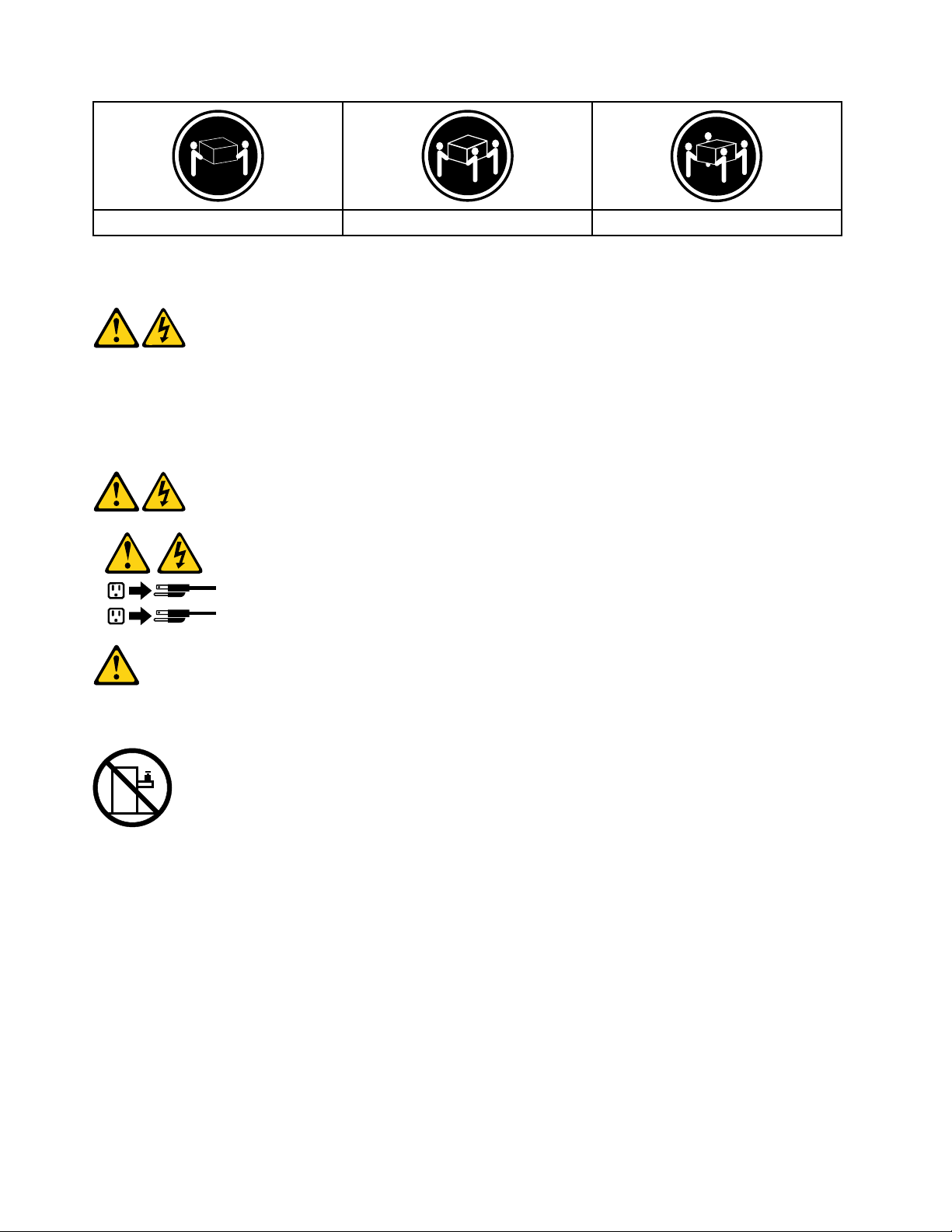
≥18kg(37lbs)≥32kg(70.5lbs)≥55kg(121.2lbs)
1
2
CAUTION:
Usesafepracticeswhenlifting.
CAUTION:
Thepowercontrolbuttononthedeviceandthepowerswitchonthepowersupplydonotturnoff
theelectricalcurrentsuppliedtothedevice.Thedevicealsomighthavemorethanonepower
cord.T oremoveallelectricalcurrentfromthedevice,ensurethatallpowercordsaredisconnected
fromthepowersource.
CAUTION:
Donotplaceanyobjectweighingmorethan82kg(180lbs.)ontopofrack-mounteddevices.
8ideacentreAll-In-One700HardwareMaintenanceManual
Page 15

Chapter3.Generalinformation
Thischapterprovidesgeneralinformationthatappliestoallcomputermodelscoveredbythismanual.
Specifications
Thissectionliststhephysicalspecificationsforyourcomputer.
Thissectionliststhephysicalspecificationsforyourcomputer.
Thissectionliststhephysicalspecifications.
Environment
Airtemperature:
Operating:10°to35°C
Transit:-20°to55°C
Humidity:
Operating:35%to80%
Transit:20%to90%(40°C)
Altitude:86KPato106KPa
Electricalinput:
Inputvoltage:90V-264V(AC)
Inputfrequency:47Hz-63Hz
©CopyrightLenovo2015
9
Page 16

10ideacentreAll-In-One700HardwareMaintenanceManual
Page 17

Chapter4.GeneralCheckout
Attention:Thedrivesinthecomputeryouareservicingmighthavebeenrearrangedorthedrivestartup
sequencemayhavebeenchanged.Beextremelycarefulduringwriteoperationssuchascopying,saving,or
formatting.Dataorprogramscanbeoverwrittenifyouselectanincorrectdrive.
Generalerrormessagesappearifaproblemorconflictisfoundbyanapplication,theoperatingsystem,or
both.Foranexplanationofthesemessages,refertotheinformationsuppliedwiththatsoftwarepackage.
Usethefollowingproceduretohelpdeterminethecauseoftheproblem:
1.Power-offthecomputerandallexternaldevices.
2.Checkallcablesandpowercords.
3.Setalldisplaycontrolstothemiddleposition.
4.Power-onallexternaldevices.
5.Power-onthecomputer.
•Lookfordisplayederrorcodes.
•Lookforreadableinstructionsoramainmenuonthedisplay.
Ifyoudidnotreceivethecorrectresponse,proceedtostep6.
Ifyoudidreceivethecorrectresponse,proceedtostep7.
6.Ifoneofthefollowinghappens,followtheinstructiongiven:
•IfthecomputerdisplaysaPOSTerror,goto“POSTerrorcodes” .
•Ifthecomputerhangsandnoerrorisdisplayed,continueatstep7.
7.Iftheteststopsandyoucannotcontinue,replacethelastdevicetested.
©CopyrightLenovo2015
11
Page 18

12ideacentreAll-In-One700HardwareMaintenanceManual
Page 19

Chapter5.UsingtheSetupUtility
TheSetupUtilityprogramisusedtoviewandchangetheconfigurationsettingsofyourcomputer,regardless
ofwhichoperatingsystemyouareusing.However,theoperatingsystemsettingsmightoverrideanysimilar
settingsintheSetupUtilityprogram.
StartingtheLenovoBIOSSetupUtilityprogram
TostarttheLenovoBIOSSetupUtilityprogram,dothefollowing:
1.Ifyourcomputerisalreadyonwhenyoustartthisprocedure,shutdowntheoperatingsystemand
turnoffthecomputer.
2.PressandholdtheF1key,andthenturnonthecomputer.WhentheLenovoBIOSSetupUtilityprogram
isdisplayed,releasetheF1key.
Note:IfaPower-OnPasswordoranAdministratorPasswordhasbeenset,theSetupUtilityprogrammenu
willnotbedisplayeduntilyoutypeyourpassword.Formoreinformation,see“Usingpasswords. ”
Viewingandchangingsettings
SystemconfigurationoptionsarelistedintheLenovoBIOSSetupUtilityprogrammenu.T ovieworchange
settings,see“StartingtheSetupUtilityprogram.”
YoumustusethekeyboardwhenusingtheLenovoBIOSSetupUtilitymenu.Thekeysusedtoperform
varioustasksaredisplayedonthebottomofeachscreen.
Usingpasswords
YoucanusetheLenovoBIOSSetupUtilityprogramtosetpasswordstopreventunauthorizedpersons
fromgainingaccesstoyourcomputeranddata.See“StartingtheSetupUtilityprogram. ”Thefollowing
typesofpasswordsareavailable:
•AdministratorPassword
•Power-OnPassword
Youdonothavetosetanypasswordstouseyourcomputer.However,ifyoudecidetosetpasswords,read
thefollowingsections.
Passwordconsiderations
Apasswordcanbeanycombinationoflettersandnumbersupto16characters(a-zand0-9).Forsecurity
reasons,itisagoodideatouseastrongpasswordthatcannotbeeasilycompromised.Wesuggestthat
passwordsshouldfollowtheserules:
•Forastrongpassword,use7-16charactersandamixoflettersandnumbers.
•Donotuseyournameoryourusername.
•Donotuseacommonwordoracommonname.
•Usesomethingsignificantlydifferentfromyourpreviouspassword.
Attention:AdministratorandPower-Onpasswordsarenotcasesensitive.
©CopyrightLenovo2015
13
Page 20

AdministratorPassword
SettinganAdministratorPassworddetersunauthorizedpersonsfromchangingconfigurationsettings.Y ou
mightwanttosetanAdministratorPasswordifyouareresponsibleformaintainingthesettingsofseveral
computers.
AfteryousetanAdministratorPassword,apasswordpromptisdisplayedeverytimeyouaccesstheLenovo
BIOSSetupUtilityprogram.
IfboththeAdministratorandPower-OnPasswordareset,youcantypeeitherpassword.However,youmust
useyourAdministratorPasswordtochangeanyconfigurationsettings.
Setting,changing,ordeletinganAdministratorpassword
TosetanAdministratorPassword,dothefollowing:
Note:Apasswordcanbeanycombinationoflettersandnumbersupto16characters(a-zand0-9).For
moreinformation,see“Passwordconsiderations”onpage13.
1.StarttheLenovoBIOSSetupUtilityprogram(see“StartingtheLenovoBIOSSetupUtilityprogram”on
page13).
2.FromtheSecuritymenu,selectSetAdministratorPasswordandpresstheEnterkey.
3.Thepassworddialogboxwillbedisplayed.T ypethepassword,andthenpresstheEnterkey.
4.Re-typethepasswordtoconfirm,andthenpresstheEnterkey.Ifyoutypedthepasswordcorrectly,
thepasswordwillbeinstalled.
TochangeanAdministratorPassword,dothefollowing:
1.StarttheLenovoBIOSSetupUtilityprogram(see“StartingtheLenovoBIOSSetupUtilityprogram”on
page13).
2.FromtheSecuritymenu,selectSetAdministratorPasswordandpresstheEnterkey.
3.Thepassworddialogboxwillbedisplayed.Typethecurrentpassword,andthenpresstheEnterkey.
4.Typethenewpassword,andthenpresstheEnterkey.Re-typethepasswordtoconfirmthenew
password.Ifyoutypedthenewpasswordcorrectly,thenewpasswordwillbeinstalled.ASetup
Noticedconfirmingthatchangeshavebeensavedwillbedisplayed.
TodeleteapreviouslysetAdministratorPassword,dothefollowing:
1.FromtheSecuritymenu,selectSetAdministratorPasswordandpresstheEnterkey.
2.Thepassworddialogboxwillbedisplayed.T ypethecurrentpasswordandpresstheEnterkey.
3.TodeleteanAdministratorPassword,leaveeachnewpasswordlineitemblank,andthenpressthe
Enterkey.ASetupNoticeconfirmingthatchangeshavebeensavedwillbedisplayed.
4.ReturntotheLenovoBIOSSetupUtilityprogrammenuandselecttheExitoption.
5.SelectSavechangesandExitfromthemenu.
Power-OnPassword
WhenaPower-OnPasswordisset,youcannotstarttheLenovoBIOSSetupUtilityprogramuntilavalid
passwordistypedfromthekeyboard.
Setting,changing,ordeletingaPower-OnPassword
Note:Apasswordcanbeanycombinationoflettersandnumbersupto16characters(a-zand0-9).
14ideacentreAll-In-One700HardwareMaintenanceManual
Page 21
TosetaPower-OnPassword,dothefollowing:
1.StarttheLenovoBIOSSetupUtilityprogram(See”StartingtheLenovoBIOSSetupUtilityprogram”on
page13.)
2.FromtheSecuritymenu,selectSetPower-OnPasswordandpresstheEnterkey.
3.Thepassworddialogboxwillbedisplayed.T ypethepassword,andthenpresstheEnterkey.
4.Re-typethepasswordtoconfirm.Ifyoutypedthepasswordcorrectly,thepasswordwillbeinstalled.
TochangeaPower-OnPassword,dothefollowing:
1.StarttheLenovoBIOSSetupUtilityprogram(See”StartingtheLenovoBIOSSetupUtilityprogram”on
page13.)
2.FromtheSecuritymenu,selectSetPower-OnPasswordandpresstheEnterkey.
3.Thepassworddialogboxwillbedisplayed.Typethecurrentpassword,andthenpresstheEnterkey.
4.Typethenewpassword,andthenpresstheEnterkey.Re-typethepasswordtoconfirmthenew
password.Ifyoutypedthenewpasswordcorrectly,thenewpasswordwillbeinstalled.ASetup
Noticedconfirmingthatchangeshavebeensavedwillbedisplayed.
TodeleteapreviouslysetPower-OnPassword,dothefollowing:
1.FromtheSecuritymenu,selectSetPower-OnPasswordandpresstheEnterkey.
2.Thepassworddialogboxwillbedisplayed.T ypethecurrentpasswordandpresstheEnterkey.
3.TodeletethePower-OnPassword,leaveeachnewpasswordlineitemblank,andthenpressEnter.A
SetupNoticeconfirmingthatchangeshavebeensavedwillbedisplayed.
4.ReturntotheLenovoBIOSSetupUtilityprogrammenuandselecttheExitoption.
5.SelectSavechangesandExitfromthemenu.
Enablingordisablingadevice
TheDevicesoptionsisusedtoenableordisableuseraccesstothefollowingdevices:
USBFunctionsSelectwhethertoenableordisableUSB(UniversalSerial
Bus)functions.Ifthefunctionsaredisabled,noUSB
devicescanbeused.
SATAMode
OnboardAudioControllerSelectwhethertoenableordisabletheOnboard
OnboardEthernetControllerorLANBootAgentSelectwhethertoenableordisabletheOnboardEthernet
Toenableordisableadevice,dothefollowing:
1.StarttheSetupUtilityprogram(see“StartingtheSetupUtilityprogram”onpage13).
2.FromtheSetupUtilityprogrammenu,selectDevices.
3.Selectanoptionasfollows:
WhenthisfeatureissettoDisabled,alldevices
connectedtotheSATAconnectors(e.g.harddiskdrives
ortheopticaldiskdrive)aredisabledandcannotbe
accessed.
AudioController.WhenthisfeatureissettoDisabled
alldevicesconnectedtotheaudioconnectors(e.g.
headphonesoramicrophone)aredisabledandcannot
beused.
Controller,orselectwhethertoenableordisableload
onboardPXE(PrebootExecutionEnvironment).
SelectUSBSetup,presstheEnterkey,andthenselectUSBFunctions.
Chapter5.UsingtheSetupUtility15
Page 22

SelectATADeviceSetup,presstheEnterkey,andthenselectSAT AMode.
SelectAudioSetup,presstheEnterkey,andthenselectOnboardAudioController.
SelectNetworkSetup,presstheEnterkey,andthenselectOnboardEthernetSupportorLAN
BootAgent.
4.SelectDisabledorEnabledandpresstheEnterkey.
5.ReturntotheLenovoBIOSSetupUtilityprogrammenuandselecttheExitoption.
6.SelectSavechangesandExitfromthemenu.
Notes:
a.Ifyoudonotwanttosavethesettings,selectDiscardchangesandExitfromthemenu.
b.SelectIDE/AHCIMode:DevicedriversupportisrequiredforACHI.Dependingonhowtheharddisk
imagewasinstalled,changingthissettingmaypreventthesystemfrombooting.
Selectingastartupdevice
IfyourcomputerdoesnotbootfromadevicesuchastheCD/DVD-ROMdrivediskorharddiskasexpected,
followoneoftheproceduresbelow.
Selectingatemporarystartupdevice
Usethisproceduretostartupfromanybootdevice.
Note:NotallCDs,DVDsorharddiskdrivesarebootable.
1.Turnoffyourcomputer.
2.PressandholdtheF12key,andthenturnonthecomputer.WhentheStartupDeviceMenuappears,
releasetheF12key.
Note:IftheStartupDeviceMenudoesnotdisplayusingthesesteps,repeatedlypressandreleasethe
F12keyratherthankeepingitpressedwhenturningonthecomputer.
3.Use↑and↓arrowstoselectthedesiredstartupdevicefromtheStartupDeviceMenuandpress
theEnterkeytobegin.
Note:SelectingastartupdevicefromtheStartupDeviceMenudoesnotpermanentlychangethe
startupsequence.
Selectingorchangingthestartupdevicesequence
Tovieworpermanentlychangetheconfiguredstartupdevicesequence,dothefollowing:
1.StarttheLenovoBIOSSetupUtilityprogram(see“StartingtheLenovoBIOSSetupUtilityprogram”on
page13).
2.FromtheLenovoBIOSSetupUtilityprogrammainmenu,selecttheStartupoption.
3.PresstheEnterkey,andselectthedevicesforthePrimaryBootSequence.Readtheinformation
displayedontherightsideofthescreen.
4.Use↑and↓arrowstoselectadevice.Usethe<+>or<->keystomoveadeviceupordown.Usethe
<×>keytoexcludethedevicefromorincludethedeviceinthebootsequence.
5.ReturntotheLenovoBIOSSetupUtilityprogrammenuandselecttheExitoption.
6.SelectSavechangesandExitfromthemenu.
Notes:
16ideacentreAll-In-One700HardwareMaintenanceManual
Page 23

a.Ifyoudonotwanttosavethesettings,selectDiscardchangesandExitfromthemenu.
b.Ifyouhavechangedthesesettingsandwanttoreturntothedefaultsettings,selectLoadOptimal
Defaultsfromthemenu.
ExitingtheLenovoBIOSSetupUtilityprogram
Afteryoufinishviewingorchangingsettings,presstheEsckeytoreturntotheLenovoBIOSSetupUtility
programmainmenu.YoumighthavetopresstheEsckeyseveraltimes.Dooneofthefollowing:
•Ifyouwanttosavethenewsettings,selectSavechangesandExitfromthemenu.WhentheSave&
resetwindowshows,selecttheY esbutton,andthenpresstheEnterkeytoexittheLenovoBIOS
SetupUtilityprogram.
•Ifyoudonotwanttosavethesettings,selectDiscardchangesandExitfromthemenu.Whenthe
ResetWithoutSavingwindowshows,selecttheYesbutton,andthenpresstheEnterkeytoexitthe
LenovoBIOSSetupUtilityprogram.
Chapter5.UsingtheSetupUtility17
Page 24

18ideacentreAll-In-One700HardwareMaintenanceManual
Page 25

Chapter6.Symptom-to-FRUIndex
TheSymptom-to-FRUindexlistserrorsymptomsandpossiblecauses.Themostlikelycauseislistedfirst.
AlwaysbeginwithChapter4,“GeneralCheckout,”onpage11.Thisindexcanalsobeusedtohelpyou
decidewhichFRUstohaveavailablewhenservicingacomputer.Ifyouareunabletocorrecttheproblem
usingthisindex,goto“Undeterminedproblems”onpage20.
Notes:
•Ifyouhavebothanerrormessageandanincorrectaudioresponse,diagnosetheerrormessagefirst.
•Ifyoucannotrunthediagnostictestsoryougetadiagnosticerrorcodewhenrunningatestbutdid
receiveaPOSTerrormessage,diagnosethePOSTerrormessagefirst.
•Ifyoudidnotreceiveanyerrormessagelookforadescriptionofyourerrorsymptomsinthefirstpartof
thisindex.
Harddiskdrivebooterror
Aharddiskdrivebooterrorcanbecausedbythefollowing.
Error
Thestartupdriveisnotincludedinthebootsequence
configuration.
Nooperatingsystemisinstalledonthebootdrive.Installanoperatingsystemonthebootdrive.
Thebootsectoronthestartupdriveiscorrupted.
Thedriveisdefective.
FRU/Action
Checktheconfigurationandensurethestartupdriveis
inthebootsequence.
Thedrivemustbeformatted.Dothefollowing:
1.Attempttobackupthedataonthefailingharddisk
drive.
2.Usetheoperatingsystemtoformattheharddisk
drive.
Replacetheharddiskdrive.
PowerSupplyProblems
Followtheseproceduresifyoususpectthereisapowersupplyproblem.
Check/VerifyFRU/Action
Checkthatthefollowingareproperlyinstalled:
•PowerCord
•On/OffSwitchconnector
•SystemBoardPowerSupplyconnectors
•Microprocessorconnections
Checkthepowercord.PowerCord
Checkthepower-onswitch.Power-onSwitch
Reseatconnectors
©CopyrightLenovo2015
19
Page 26

POSTerrorcodes
Eachtimeyouturnthecomputeron,itperformsaseriesofteststocheckthatthesystemisoperating
correctlyandthatcertainoptionsareset.ThisseriesoftestsiscalledthePower-OnSelf-Test,orPOST.
POSTdoesthefollowing:
•Checkssomebasicmotherboardoperations
•Checksthatthememoryisworkingcorrectly
•Startsvideooperations
•Verifiesthatthebootdriveisworking
POSTErrorMessageDescription/Action
Keyboarderror
RebootandSelectproperBootdeviceorInsertBoot
MediainselectedBootdevice
Cannotinitializethekeyboard.Makesurethekeyboard
isproperlyconnectedtothecomputerandthatnokeys
areheldpressedduringPOST.T opurposelyconfigure
thecomputerwithoutakeyboard,selectKeyboardless
operationinStartupandsettheoptiontoEnabled.The
BIOSthenignoresthemissingkeyboardduringPOST.
TheBIOSwasunabletofindasuitablebootdevice.Make
surethebootdriveisproperlyconnectedtothecomputer .
Makesureyouhavebootablemediainthebootdevice.
Undeterminedproblems
1.Power-offthecomputer.
2.Removeordisconnectthefollowingcomponents(ifconnectedorinstalled)oneatatime.
a.Externaldevices(modem,printer,ormouse)
b.Extendedvideomemory
c.ExternalCache
d.ExternalCacheRAM
e.Harddiskdrive
f.Diskdrive
3.Power-onthecomputertore-testthesystem.
4.Repeatsteps1through3untilyoufindthefailingdeviceorcomponent.
Ifalldevicesandcomponentshavebeenremovedandtheproblemcontinues,replacethesystemboard.
20ideacentreAll-In-One700HardwareMaintenanceManual
Page 27

Chapter7.Hardwarecomponents
6
7
8
9
10
11
12
13
14
15
16
17
18
19
20
21
22
23
24
25
26
27
28
5
1
2
3
4
Thefollowingillustrationshowsthecomponentsthatmakeupyourcomputer.
1.Systemfan
2.Chassis
3.Heatsink17.EMIcover
15.Memoryshielding
16.Middlecover
4.Harddiskdrive18.Motherboard
5.LCDPanel
6.Powersupplyunit20.Powerswitchboard
7.Speaker
8.Opticaldrivebracket22.NFCmodule
9.Opticaldrive23.Converterboard
10.Solidstatedrive
11.Footcover25.2Dwebcammodule
12.SideI/Oshielding26.3DwebcamMICmodule
13.Computerstand27.ACbracket
14.Reardeco28.Powerconnector
©CopyrightLenovo2015
19.Wi-Ficard
21.Mainframe
24.3Dwebcammodule
21
Page 28

IdentifyingpartsonthemotherboardofAIO700–24ISH(FHD)andAIO700–27ISH(FHD)
1
2
3
6
7
8
9
10 11 12 13 14 15 1 6 17
18
19
20
21
22
23
24
2526272 8
4
5
1.Systemfanconnector15.USB3.0connector
2.Powerconnector16.HDMI-inconnector
3.SAT Apowerconnector17.Speakerconnector
4.OpticaldriveSATAconnector
18.Memoryslot
5.HarddiskdriveSATAconnector19.AUDIOconnector
6.Powersupplyunitconnector
20.Cardreaderconnector
7.LVDSconnector21.USB3.0connector
9.Converterconnector23.CPUsocket
10.NFCconnector
11.Ethernetconnector25.Batteryslot
12.HDMI-outconnector
13.USB2.0connector
14.USB2.0connector
8.Touchpanelconnector
22.USB3.0connector
24.Wi-Ficardconnector
26.3DMICconnector
27.3Dwebcamconnector
28.2Dwebcamconnector
22ideacentreAll-In-One700HardwareMaintenanceManual
Page 29

IdentifyingpartsonthemotherboardofAIO700–24ISH(UHD)andAIO700–27ISH(UHD)
1
2
3
6
7
9
8
10
11 1 2 13 14 15 16 17 1 8
19
20
21
22
24
23
25
2627282 9
4
5
1.Systemfanconnector16.USB3.0connector
2.Powerconnector17.HDMI-inconnector
3.SAT Apowerconnector18.Speakerconnector
4.OpticaldriveSATAconnector
19.Memoryslot
5.HarddiskdriveSATAconnector20.AUDIOconnector
6.Powersupplyunitconnector
21.Cardreaderconnector
7.3OPEDP22.USB3.0connector
8.4OPEDP23.USB3.0connector
9.Touchpanelconnector
10.Converterconnector
11.NFCconnector
12.Ethernetconnector
13.HDMI-outconnector28.3Dwebcamconnector
14.USB2.0connector
24.CPUsocket
25.Wi-Ficardconnector
26.Battery
27.3DMICconnector
29.2Dwebcamconnector
15.USB2.0connector
Chapter7.Hardwarecomponents23
Page 30

IdentifyingpartsonthemotherboardofAIO700–24AGR
1
2
3
6
7
9
8
10
11 12 13 14 15 1 6 17 18
19
20
21
22
24
23
25
26
4
5
1.Systemfanconnector14.USB2.0connector
2.Powerconnector
3.SAT Apowerconnector16.USB3.0connector
4.OpticaldriveSATAconnector
15.USB2.0connector
17.HDMI-inconnector
5.HarddiskdriveSATAconnector18.Speakerconnector
6.Powersupplyunitconnector19.Memoryslot
7.Battery
20.AUDIOconnector
8.LVDSconnector21.Cardreaderconnector
9.Touchpanelconnector
22.USB3.0connector
10.Converterconnector23.USB3.0connector
11.NFCconnector24.CPUsocket
12.Ethernetconnector25.Wi-Ficardconnector
13.HDMI-outconnector26.2Dwebcamconnector
24ideacentreAll-In-One700HardwareMaintenanceManual
Page 31

Chapter8.Replacinghardware
Attention:Donotremovethecomputercoverorattemptanyrepairbeforereadingthe“Importantsafetyinformation”
intheSafetyandWarrantyGuidethatwasincludedwithyourcomputer.T oobtaincopiesoftheSafetyandWarranty
Guide,gototheSupportWebsiteat:http://consumersupport.lenovo.com.
Note:UseonlypartsprovidedbyLenovo.
Generalinformation
Pre-disassemblyinstructions
Beforestartingthedisassemblyprocedure,makesurethatyoudothefollowing:
1.Turnoffthepowertothesystemandallperipherals.
2.Unplugallpowerandsignalcablesfromthecomputer.
3.Placethesystemonaflat,stablesurface.
©CopyrightLenovo2015
25
Page 32

Replacingthekeyboardandmouse
Note:Y ourkeyboardwillbeconnectedtoaUSBconnectorateithersideorattherearofthecomputer.
Toreplacethekeyboardandmouse:
Step1.Removeanymedia(disks,CDs,ormemorycards)fromthedrives,shutdownthecomputer,and
turnoffallattacheddevices.
Step2.Unplugallpowercordsfromelectricaloutlets.
Step3.Locatetheconnectorforthekeyboard.Referto“Sideviewofthecomputer”and“Rearviewof
thecomputer”.
Step4.Disconnectthedefectivekeyboardcablefromthecomputerandconnectthenewkeyboardcable
tothesameconnector.
Step5.Themousecanbereplacedusingthesamemethod.
Replacingthepowercord
Attention:T urnoffthecomputerandwait3to5minutestoletitcooldownbeforeremovingthecover.
Step1.Removeanymedia(disks,CDs,ormemorycards)fromthedrives,shutdowntheoperating
system,andturnoffthecomputerandallattacheddevices.
26ideacentreAll-In-One700HardwareMaintenanceManual
Page 33

Step2.Unplugthepowercordfromelectricaloutlet1,andthendisconnectthepowercordfromthe
1
2
2
1
connectoronthecomputer
2.
Step3.Connectthenewpowercordasshown.
Removingthestandbase
Attention:T urnoffthecomputerandwait3to5minutestoletitcooldownbeforeremovingthecover.
Note:Itmaybehelpfultoplacethecomputerface-downonasoftflatsurfaceforthisprocedure.Lenovo
recommendsthatyouuseablanket,towel,orothersoftclothtoprotectthetouchscreenfromscratches
orotherdamage.
Step1.Removeanymedia(disks,CDs,ormemorycards)fromthedrives,shutdowntheoperating
system,andturnoffthecomputerandallattacheddevices.
Step2.Unplugallpowercordsfromelectricaloutlets.
Chapter8.Replacinghardware27
Page 34

Step3.Disconnectallcablesattachedtothecomputer.Thisincludespowercords,input/output(I/O)
1
2
3
cables,andanyothercablesthatareconnectedtothecomputer.Referto“Leftandrightviews”
and“Rearview”forhelpwithlocatingthevariousconnectors.
Step4.Opentherubbercover,andthentwistthehandscrewringcounter-clockwiseuntilthebasecomes
loosetoreleasethestandbasefromthestandholder.12
Step5.Slidethestandbaseoutfromtheholder,andthenputitaside.3
Step6.Referto“Installingthecomputerstand”toreinstallthestandbase.
Removingthefootcover
Attention:T urnoffthecomputerandwait3to5minutestoletitcooldownbeforeremovingthecover.
Note:Itmaybehelpfultoplacethecomputerface-downonasoftflatsurfaceforthisprocedure.Lenovo
recommendsthatyouuseablanket,towel,orothersoftclothtoprotectthetouchscreenfromscratches
orotherdamage.
Step1.Removeanymedia(disks,CDs,ormemorycards)fromthedrives,shutdowntheoperating
system,andturnoffthecomputerandallattacheddevices.
Step2.Unplugallpowercordsfromelectricaloutlets.
Step3.Disconnectallcablesattachedtothecomputer.Thisincludespowercords,input/output(I/O)
cables,andanyothercablesthatareconnectedtothecomputer.Referto“Leftandrightviews”
and“Rearview”forhelpwithlocatingthevariousconnectors.
Step4.Removethestandbase.Referto“Removingthestandbase”.
28ideacentreAll-In-One700HardwareMaintenanceManual
Page 35

Step5.Liftupthestandholder,andthenslideoutthefootcoverasshown.
1
2
Step6.T oreattachthefootcover:
a.Liftupthestandholder.
b.Lineupthefootcoverwithmountingholesonthebackofthecomputer,andthenslideit
backintoposition.
Replacingthememorymodule
Attention:T urnoffthecomputerandwait3to5minutestoletitcooldownbeforeremovingthecover.
Note:Itmaybehelpfultoplacethecomputerface-downonasoftflatsurfaceforthisprocedure.Lenovo
recommendsthatyouuseablanket,towel,orothersoftclothtoprotectthetouchscreenfromscratches
orotherdamage.
Step1.Removeanymedia(disks,CDs,ormemorycards)fromthedrives,shutdowntheoperating
system,andturnoffthecomputerandallattacheddevices.
Step2.Unplugallpowercordsfromelectricaloutlets.
Step3.Disconnectallcablesattachedtothecomputer.Thisincludespowercords,input/output(I/O)
cables,andanyothercablesthatareconnectedtothecomputer.Referto“Leftandrightviews”
and“Rearview”forhelpwithlocatingthevariousconnectors.
Step4.Removethestandbase.Referto“Removingthestandbase”.
Step5.Removethefootcover.Referto“Removingthefootcover” .
Chapter8.Replacinghardware29
Page 36

Step6.Removethememoryshielding.
Step7.Pushoutthelatchesonbothsidesofthememorysockettoreleasethememorymoduleandgently
pullthememorymoduleupwardtoremoveitfromitssocket.
Step8.T oinstallthenewmemorymodule:
a.Alignthenewmemorymodulewiththememoryslot,andtheninsertitandpushdownonthe
topedge.Makesurethelatcheslockthememorymoduleinplace.
b.Reattachthememoryshielding.
Step9.Reattachthefootcoverandstandbase.
Replacingtheharddiskdrive
Attention:T urnoffthecomputerandwait3to5minutestoletitcooldownbeforeremovingthecover.
Note:Itmaybehelpfultoplacethecomputerface-downonasoftflatsurfaceforthisprocedure.Lenovo
recommendsthatyouuseablanket,towel,orothersoftclothtoprotectthetouchscreenfromscratches
orotherdamage.
Step1.Removeanymedia(disks,CDs,ormemorycards)fromthedrives,shutdowntheoperating
system,andturnoffthecomputerandallattacheddevices.
Step2.Unplugallpowercordsfromelectricaloutlets.
Step3.Disconnectallcablesattachedtothecomputer.Thisincludespowercords,input/output(I/O)
cables,andanyothercablesthatareconnectedtothecomputer.Referto“Leftandrightviews”
and“Rearview”forhelpwithlocatingthevariousconnectors.
Step4.Removethestandbase.Referto“Removingthestandbase”.
Step5.Removethefootcover.Referto“Removingthefootcover” .
30ideacentreAll-In-One700HardwareMaintenanceManual
Page 37

Step6.Liftouttheharddiskdriveandbracketasshown.
Step7.Pushthelockpinsoutwardtoreleasetheharddiskdrivefromthebracket.
Step8.T oinstallthenewharddiskdrive:
a.Lineupthenewharddiskdrivewiththebracketandsecureitwiththepins.
b.Connectthedataandpowercablestothenewharddiskdrive.
c.Slidetheharddiskdriveandbracketbackintoposition.
Step9.Reattachthefootcoverandstandbase.
Replacingtheopticaldrive
Attention:T urnoffthecomputerandwait3to5minutestoletitcooldownbeforeremovingthecover.
Note:Itmaybehelpfultoplacethecomputerface-downonasoftflatsurfaceforthisprocedure.Lenovo
recommendsthatyouuseablanket,towel,orothersoftclothtoprotectthetouchscreenfromscratches
orotherdamage.
Step1.Removeanymedia(disks,CDs,ormemorycards)fromthedrives,shutdowntheoperating
system,andturnoffthecomputerandallattacheddevices.
Step2.Unplugallpowercordsfromelectricaloutlets.
Step3.Disconnectallcablesattachedtothecomputer.Thisincludespowercords,input/output(I/O)
cables,andanyothercablesthatareconnectedtothecomputer.Referto“Leftandrightviews”
and“Rearview”forhelpwithlocatingthevariousconnectors.
Step4.Removethestandbase.Referto“Removingthestandbase”.
Step5.Removethefootcover.Referto“Removingthefootcover” .
Chapter8.Replacinghardware31
Page 38

Step6.Locatetheopticalremovalnotch,andthenpushtheopticaldriveoutusingascrewdriver.
Step7.Pushasmallironstickorpaperclipintothesmallholeontheopticaldrivecoversothatthe
diskspringsoutasshown.
Step8.Useasmallflatheadscrewdrivertopressandpushoutthepinsthatsecurethecovertothe
disk.12
Step9.Separatethecoverfromthedefectiveopticaldrive.
Step10.Toinstallthenewopticaldrive:
32ideacentreAll-In-One700HardwareMaintenanceManual
Page 39

a.Alignthenewopticaldrivewiththecover,andthenpushthecoverbackintoposition.
1
b.Slidethenewopticaldriveintothedrivebay.
Step11.Reattachthefootcoverandstandbase.
Removingthestandholder
Note:T urnoffthecomputerandwait3to5minutestoletitcooldownbeforeremovingthecover.
Note:Itmaybehelpfultoplacethecomputerface-downonasoftflatsurfaceforthisprocedure.Lenovo
recommendsthatyouuseablanket,towel,orothersoftclothtoprotectthecomputerscreenfromscratches
orotherdamage.
Toremovethestandholder:
Step1.Removeanymedia(disks,CDs,DVDs,ormemorycards)fromthedrives,shutdowntheoperating
system,andturnoffthecomputerandallattacheddevices.
Step2.Unplugallpowercordsfromelectricaloutlets.
Step3.Disconnectallcablesattachedtothecomputer.Thisincludespowercords,input/output(I/O)
cables,andanyothercablesthatareconnectedtothecomputer.Referto“Leftandrightview”
and“Rearview”forhelpwithlocatingthevariousconnectors.
Step4.Removethestandbase.Referto“Removingthestandbase”.
Step5.Removethefootcover.Referto“Removingthefootcover” .
Step6.Removethefourscrewsthatsecurethestandholdertothechassis,andthenliftupthestand
holdertoremoveit.
Step7.T oreattachthestandholder:
a.Aligntheholesonthestandholderwithmountingholesonthechassis,placethestand
holderbackintoposition.
b.Securethestandholdertothechassiswiththefourscrews.
Step8.Lineupthefootcoverwithmountingholesonthebackofthecomputer,andthenslideitback
Step9.Reattachthestandbase.
intoposition.
Removingthemiddlecover
Note:T urnoffthecomputerandwait3to5minutestoletitcooldownbeforeremovingthecover.
Chapter8.Replacinghardware33
Page 40

Note:Itmaybehelpfultoplacethecomputerface-downonasoftflatsurfaceforthisprocedure.Lenovo
recommendsthatyouuseablanket,towel,orothersoftclothtoprotectthecomputerscreenfromscratches
orotherdamage.
Toremovethemiddlecover:
Step1.Removeanymedia(disks,CDs,DVDs,ormemorycards)fromthedrives,shutdowntheoperating
system,andturnoffthecomputerandallattacheddevices.
Step2.Unplugallpowercordsfromelectricaloutlets.
Step3.Disconnectallcablesattachedtothecomputer.Thisincludespowercords,input/output(I/O)
cables,andanyothercablesthatareconnectedtothecomputer.Referto“Leftandrightview”
and“Rearview”forhelpwithlocatingthevariousconnectors.
Step4.Removethestandbase.Referto“Removingthestandbase”.
Step5.Removethefootcover.Referto“Removingthefootcover” .
Step6.Removetheopticaldrive.Referto“Replacingtheopticaldrive”.
Step7.Removethestandholder.Referto“Removingthestandholder” .
Step8.Removethescrewsthatsecurethemiddlecovertothechassis.
Step9.Liftupthemiddlecoverasshowntoremoveit.
34ideacentreAll-In-One700HardwareMaintenanceManual
Page 41

Step10.Toreattachthemiddlecover:
a.Lineupthemiddlecoverwithchassis,andthenplacethemiddlecoverback.
b.Securethemiddlecovertothechassiswiththescrews.
Step11.Reattachthestandholder,opticaldrive,footcoverandstandbase.
Replacingtheconverterboard
Note:T urnoffthecomputerandwait3to5minutestoletitcooldownbeforeremovingthecover.
Note:Itmaybehelpfultoplacethecomputerface-downonasoftflatsurfaceforthisprocedure.Lenovo
recommendsthatyouuseablanket,towel,orothersoftclothtoprotectthecomputerscreenfromscratches
orotherdamage.
Toreplacetheconverterboard:
Step1.Removeanymedia(disks,CDs,DVDs,ormemorycards)fromthedrives,shutdowntheoperating
system,andturnoffthecomputerandallattacheddevices.
Step2.Unplugallpowercordsfromelectricaloutlets.
Step3.Disconnectallcablesattachedtothecomputer.Thisincludespowercords,input/output(I/O)
cables,andanyothercablesthatareconnectedtothecomputer.Referto“Leftandrightview”
and“Rearview”forhelpwithlocatingthevariousconnectors.
Step4.Removethestandbase.Referto“Removingthestandbase”.
Step5.Removethefootcover.Referto“Removingthefootcover” .
Step6.Removethestandholder.Referto“Removingthestandholder” .
Step7.Removethemiddlecover.Referto“Removingthemiddlecover”.
Chapter8.Replacinghardware35
Page 42

Step8.Disconnectthetwocablesfromtheconverter.
Step9.Removethetwoscrewsthatsecuretheconverterboardtothechassis,andthenremovethe
converter.
Step10.Toinstallthenewconverterboard:
a.Connectthetwocablestothenewconverterboard.
b.Alignthenewconverterboardintoposition.
c.Securethenewconverterboardwiththetwoscrews.
Step11.Reattachthemiddlecover,standholder,footcoverandstandbase.
RemovingtheEMIcover
Note:T urnoffthecomputerandwait3to5minutestoletitcooldownbeforeremovingthecover.
Note:Itmaybehelpfultoplacethecomputerface-downonasoftflatsurfaceforthisprocedure.Lenovo
recommendsthatyouuseablanket,towel,orothersoftclothtoprotectthecomputerscreenfromscratches
orotherdamage.
ToreplacetheEMIcover
Step1.Removeanymedia(disks,CDs,DVDs,ormemorycards)fromthedrives,shutdowntheoperating
system,andturnoffthecomputerandallattacheddevices.
Step2.Unplugallpowercordsfromelectricaloutlets.
Step3.Disconnectallcablesattachedtothecomputer.Thisincludespowercords,input/output(I/O)
cables,andanyothercablesthatareconnectedtothecomputer.Referto“Leftandrightview”
and“Rearview”forhelpwithlocatingthevariousconnectors.
Step4.Removethestandbase.Referto“Removingthestandbase”.
Step5.Removethefootcover.Referto“Removingthefootcover” .
Step6.Removethestandholder.Referto“Removingthestandholder” .
Step7.Removethemiddlecover.Referto“Removingthemiddlecover”.
36ideacentreAll-In-One700HardwareMaintenanceManual
Page 43

Step8.RemovetheI/Oshielding.
Step9.RemovethescrewsthatsecuretheEMIcovertothechassis,andthenliftitup.
Step10.ToreattachtheEMIcover:
a.LineuptheholesontheEMIcoverwithmountingholesonthechassis,andthenplaceEMI
coverbackintoposition.
b.SecuretheEMIcovertothechassiswiththescrews.
c.LineuptheholeontheI/OshieldingwiththemountingholeontheEMIcover.
Step11.Reattachthemiddlecover,standholder,footcoverandstandbase.
ReplacingtheWi-Ficard
Note:T urnoffthecomputerandwait3to5minutestoletitcooldownbeforeremovingthecover.
Note:Itmaybehelpfultoplacethecomputerface-downonasoftflatsurfaceforthisprocedure.Lenovo
recommendsthatyouuseablanket,towel,orothersoftclothtoprotectthecomputerscreenfromscratches
orotherdamage.
ToreplacetheWi-Ficard:
Step1.Removeanymedia(disks,CDs,DVDs,ormemorycards)fromthedrives,shutdowntheoperating
system,andturnoffthecomputerandallattacheddevices.
Step2.Unplugallpowercordsfromelectricaloutlets.
Step3.Disconnectallcablesattachedtothecomputer.Thisincludespowercords,input/output(I/O)
cables,andanyothercablesthatareconnectedtothecomputer.Referto“Leftandrightview”
and“Rearview”forhelpwithlocatingthevariousconnectors.
Step4.Removethestandbase.Referto“Removingthestandbase”.
Step5.Removethefootcover.Referto“Removingthefootcover” .
Step6.Removethestandholder.Referto“Removingthestandholder” .
Step7.Removethemiddlecover.Referto“Removingthemiddlecover”.
Step8.RemovetheEMIcover.Referto“RemovingtheEMIcover” .
Chapter8.Replacinghardware37
Page 44

Step9.DisconnecttheantennacablesfromtheWi-Ficard.1
Step10.RemovethescrewthatsecurestheWi-Ficardtothemotherboard.2
Step11.LiftuptheWi-Ficardtoremoveitfromthesocket.
Step12.ToinstallthenewWi-Ficard:
a.InsertthenotchedendoftheWi-Ficardintothecardportonthemotherboard.
b.SecurenewtheWi-Ficardtothemotherboardwiththescrew.
c.ConnecttheantennacablestothenewWi-Ficard.
Step13.ReattachtheEMIcover,middlecover,standholder,footcoverandstandbase.
Replacingtheheat-sink
Note:T urnoffthecomputerandwait3to5minutestoletitcooldownbeforeremovingthecover.
Note:Itmaybehelpfultoplacethecomputerface-downonasoftflatsurfaceforthisprocedure.Lenovo
recommendsthatyouuseablanket,towel,orothersoftclothtoprotectthecomputerscreenfromscratches
orotherdamage.
Toreplacetheheat-sink:
Step1.Removeanymedia(disks,CDs,DVDs,ormemorycards)fromthedrives,shutdowntheoperating
system,andturnoffthecomputerandallattacheddevices.
Step2.Unplugallpowercordsfromelectricaloutlets.
Step3.Disconnectallcablesattachedtothecomputer.Thisincludespowercords,input/output(I/O)
cables,andanyothercablesthatareconnectedtothecomputer.Referto“Leftandrightview”
and“Rearview”forhelpwithlocatingthevariousconnectors.
Step4.Removethestandbase.Referto“Removingthestandbase”.
Step5.Removethefootcover.Referto“Removingthefootcover” .
Step6.Removetheopticaldrive.Referto“Replacingtheopticaldrive”.
Step7.Removethestandholder.Referto“Removingthestandholder” .
38ideacentreAll-In-One700HardwareMaintenanceManual
Page 45

Step8.Removethemiddlecover.Referto“Removingthemiddlecover”.
Step9.RemovetheEMIcover.Referto“RemovingtheEMIcover” .
Step10.Removethesealingtapebetweenthesystemfanandheat-sink.
Step11.Removetheninescrewsthatsecuretheheat-sinktothemotherboardandchassis.
Step12.Slidethenliftuptheheat-sinktoremoveit.
Attention:Placetheheat-sinkupsidedownonaflatsurfacetopreventthermalgreasefromcontaminating
othercomponents.
Attention:UseanalcoholpadtowipethethermalgreaseofftheCPU.
Step13.Toinstallthenewheat-sink:
a.Lineupthenewheat-sinkwithmountingholesonthemotherboard,andthenplaceitinto
position.
b.Followthenumbersprintedonthenewheat-sinktosecureitinorderusingthescrews.
c.Usethesealingtapetosealthegapin-betweenthesystemfanandheat-sink.
Step14.ReattachtheEMIcover,middlecover,opticaldrive,standholder,footcoverandstandbase.
ReplacinganIntelCPU
Note:T urnoffthecomputerandwait3to5minutestoletitcooldownbeforeremovingthecover.
Note:Itmaybehelpfultoplacethecomputerface-downonasoftflatsurfaceforthisprocedure.Lenovo
recommendsthatyouuseablanket,towel,orothersoftclothtoprotectthecomputerscreenfromscratches
orotherdamage.
ToreplacetheCPU
Step1.Removeanymedia(disks,CDs,DVDs,ormemorycards)fromthedrives,shutdowntheoperating
system,andturnoffthecomputerandallattacheddevices.
Step2.Unplugallpowercordsfromelectricaloutlets.
Chapter8.Replacinghardware39
Page 46

Step3.Disconnectallcablesattachedtothecomputer.Thisincludespowercords,input/output(I/O)
cables,andanyothercablesthatareconnectedtothecomputer.Referto“Leftandrightview”
and“Rearview”forhelpwithlocatingthevariousconnectors.
Step4.Removethestandbase.Referto“Removingthestandbase”.
Step5.Removethefootcover.Referto“Removingthefootcover” .
Step6.Removethestandholder.Referto“Removingthestandholder” .
Step7.Removethemiddlecover.Referto“Removingthemiddlecover”.
Step8.RemovetheEMIcover.Referto“RemovingtheEMIcover” .
Step9.Removetheheat-sink.Referto“Replacingtheheatsink” .
Step10.Liftthesmallhandleandopentheretainer.
Step11.Liftthemicroprocessorstraightupandoutofthesocket.
Attention:Donottouchthegoldcontactsonthebottomofthemicroprocessor.Whenhandlingthe
microprocessor,touchonlythesides.
Note:Donotdropanythingontothemicroprocessorsocketwhileitisexposed.Thesocketpinsmust
bekeptascleanaspossible.
40ideacentreAll-In-One700HardwareMaintenanceManual
Page 47

Step12.Holdingthesidesofthemicroprocessorwithyourfingers,removetheprotectivecover1that
protectsthegoldcontactsonthenewmicroprocessor.
2
Step13.Holdingthesidesofthemicroprocessorwithyourfingers,positionthemicroprocessorsothatthe
notchesonthemicroprocessorarealignedwiththetabsinthemicroprocessorsocket.
Important:T oavoiddamagingthemicroprocessorcontacts,keepthemicroprocessorcompletelylevel
whileinstallingitintothesocket.
Step14.Lowerthemicroprocessorstraightdownintoitssocketonthemotherboard.
Step15.Tosecurethemicroprocessorinthesocket,closethemicroprocessorretainerandlockitinto
positionwiththesmallhandle.
Step16.Useathermalgreasesyringetoplace5dropsofgreaseonthetopofthemicroprocessor.Each
dropofgreaseshouldbe0.03ml(3tickmarksonthegreasesyringe).
Step17.Reattachtheheat-sink,EMIcover,middlecover,standholder,footcoverandstandbase.
ReplacinganAMDCPU
Note:T urnoffthecomputerandwait3to5minutestoletitcooldownbeforeremovingthecover.
Chapter8.Replacinghardware41
Page 48

Note:Itmaybehelpfultoplacethecomputerface-downonasoftflatsurfaceforthisprocedure.Lenovo
recommendsthatyouuseablanket,towel,orothersoftclothtoprotectthecomputerscreenfromscratches
orotherdamage.
ToreplacetheCPU
Step1.Removeanymedia(disks,CDs,DVDs,ormemorycards)fromthedrives,shutdowntheoperating
system,andturnoffthecomputerandallattacheddevices.
Step2.Unplugallpowercordsfromelectricaloutlets.
Step3.Disconnectallcablesattachedtothecomputer.Thisincludespowercords,input/output(I/O)
cables,andanyothercablesthatareconnectedtothecomputer.Referto“Leftandrightview”
and“Rearview”forhelpwithlocatingthevariousconnectors.
Step4.Removethestandbase.Referto“Removingthestandbase”.
Step5.Removethefootcover.Referto“Removingthefootcover” .
Step6.Removethestandholder.Referto“Removingthestandholder” .
Step7.Removethemiddlecover.Referto“Removingthemiddlecover”.
Step8.RemovetheEMIcover.Referto“RemovingtheEMIcover” .
Step9.Removetheheat-sink.Referto“Replacingtheheatsink” .
Step10.Liftthesmallhandleandopentheretainer.12
Step11.Liftthemicroprocessorstraightupandoutofthesocket.3
Attention:Donottouchthegoldcontactsonthebottomofthemicroprocessor.Whenhandlingthe
microprocessor,touchonlythesides.
Note:Donotdropanythingontothemicroprocessorsocketwhileitisexposed.Thesocketpinsmust
bekeptascleanaspossible.
42ideacentreAll-In-One700HardwareMaintenanceManual
Page 49

Step12.Holdingthesidesofthemicroprocessorwithyourfingers,removetheprotectivecover1that
protectsthegoldcontactsonthenewmicroprocessor.
2
Step13.Holdingthesidesofthemicroprocessorwithyourfingers,positionthemicroprocessorsothatthe
notchesonthemicroprocessorarealignedwiththetabsinthemicroprocessorsocket.
Important:T oavoiddamagingthemicroprocessorcontacts,keepthemicroprocessorcompletelylevel
whileinstallingitintothesocket.
Step14.Lowerthemicroprocessorstraightdownintoitssocketonthemotherboard.
Step15.Tosecurethemicroprocessorinthesocket,closethemicroprocessorretainerandlockitinto
positionwiththesmallhandle.
Chapter8.Replacinghardware43
Page 50

Step16.Useathermalgreasesyringetoplace5dropsofgreaseonthetopofthemicroprocessor.Each
dropofgreaseshouldbe0.03ml(3tickmarksonthegreasesyringe).
Step17.Reattachtheheat-sink,EMIcover,middlecover,standholder,footcoverandstandbase.
Replacingthesystemfan
Note:T urnoffthecomputerandwait3to5minutestoletitcooldownbeforeremovingthecover.
Note:Itmaybehelpfultoplacethecomputerface-downonasoftflatsurfaceforthisprocedure.Lenovo
recommendsthatyouuseablanket,towel,orothersoftclothtoprotectthecomputerscreenfromscratches
orotherdamage.
Toreplacethesystemfan
Step1.Removeanymedia(disks,CDs,DVDs,ormemorycards)fromthedrives,shutdowntheoperating
system,andturnoffthecomputerandallattacheddevices.
Step2.Unplugallpowercordsfromelectricaloutlets.
Step3.Disconnectallcablesattachedtothecomputer.Thisincludespowercords,input/output(I/O)
cables,andanyothercablesthatareconnectedtothecomputer.Referto“Leftandrightview”
and“Rearview”forhelpwithlocatingthevariousconnectors.
Step4.Removethestandbase.Referto“Removingthestandbase”.
Step5.Removethefootcover.Referto“Removingthefootcover” .
Step6.Removetheopticaldrive.Referto“Replacingtheopticaldrive”.
Step7.Removethestandholder.Referto“Removingthestandholder” .
Step8.Removethemiddlecover.Referto“Removingthemiddlecover”.
Step9.RemovetheEMIcover.Referto“RemovingtheEMIcover” .
Step10.Removethesealingtapebetweenthesystemfanandheat-sink.
Step11.Removethethreescrewsthatsecurethesystemfantothechassis.
Step12.Disconnectthepowercablefromthemotherboard.
Step13.Liftupthesystemfantoremoveit.
Step14.Toinstallthenewsystemfan:
a.Placethenewsystemfanintoposition,andthensecureittothechassiswiththreescrews.
44ideacentreAll-In-One700HardwareMaintenanceManual
Page 51

b.Connectthesystemfanpowercabletotheconnectoronthemotherboard.
c.Usethesealingtapetosealthegapin-betweenthesystemfanandheat-sink.
Step15.ReattachtheEMIcover,middlecover,opticaldrive,standholder,footcoverandstandbase.
Replacingthespeakersystem
Note:T urnoffthecomputerandwait3to5minutestoletitcooldownbeforeremovingthecover.
Note:Itmaybehelpfultoplacethecomputerface-downonasoftflatsurfaceforthisprocedure.Lenovo
recommendsthatyouuseablanket,towel,orothersoftclothtoprotectthecomputerscreenfromscratches
orotherdamage.
Toreplacethespeakersystem:
Step1.Removeanymedia(disks,CDs,DVDs,ormemorycards)fromthedrives,shutdowntheoperating
system,andturnoffthecomputerandallattacheddevices.
Step2.Unplugallpowercordsfromelectricaloutlets.
Step3.Disconnectallcablesattachedtothecomputer.Thisincludespowercords,input/output(I/O)
cables,andanyothercablesthatareconnectedtothecomputer.Referto“Leftandrightview”
and“Rearview”forhelpwithlocatingthevariousconnectors.
Step4.Removethestandbase.Referto“Removingthestandbase”.
Step5.Removethefootcover.Referto“Removingthefootcover” .
Step6.Removetheopticaldrive.Referto“Replacingtheopticaldrive”.
Step7.Removethestandholder.Referto“Removingthestandholder” .
Step8.Removethemiddlecover.Referto“Removingthemiddlecover”.
Step9.RemovetheEMIcover.Referto“RemovingtheEMIcover” .
Step10.Disconnectthespeakercablesfromtheconnectoronthemotherboard.
Step11.Removethefourscrewsthatsecurethespeakersystemtothechassis,andthenliftupthespeaker
systemtoremoveit.
Step12.Toinstallthenewspeakersystem:
a.Placethenewspeakersystemintoposition,andthensecureitwithfourscrews.
b.Connectthenewspeakercablestotheconnectoronthemotherboard.
Chapter8.Replacinghardware45
Page 52

Step13.ReattachtheEMIcover,middlecover,opticaldrive,standholder,footcoverandstandbase.
Replacingthepowerswitchboard
Note:T urnoffthecomputerandwait3to5minutestoletitcooldownbeforeremovingthecover.
Note:Itmaybehelpfultoplacethecomputerface-downonasoftflatsurfaceforthisprocedure.Lenovo
recommendsthatyouuseablanket,towel,orothersoftclothtoprotectthecomputerscreenfromscratches
orotherdamage.
Toreplacethepowerswitchboard
Step1.Removeanymedia(disks,CDs,DVDs,ormemorycards)fromthedrives,shutdowntheoperating
system,andturnoffthecomputerandallattacheddevices.
Step2.Unplugallpowercordsfromelectricaloutlets.
Step3.Disconnectallcablesattachedtothecomputer.Thisincludespowercords,input/output(I/O)
cables,andanyothercablesthatareconnectedtothecomputer.Referto“Leftandrightview”
and“Rearview”forhelpwithlocatingthevariousconnectors.
Step4.Removethestandbase.Referto“Removingthestandbase”.
Step5.Removethefootcover.Referto“Removingthefootcover” .
Step6.Removetheopticaldrive.Referto“Replacingtheopticaldrive”.
Step7.Removethestandholder.Referto“Removingthestandholder” .
Step8.Removethemiddlecover.Referto“Removingthemiddlecover”.
46ideacentreAll-In-One700HardwareMaintenanceManual
Page 53

Step9.Disconnectthedatacablefromthepowerswitchboard.1
Step10.Pushthelockingpinoutwardtoreleasethepowerswitchboard,andthenliftupthepowerswitch
boardtoremoveit.2
Step11.Toinstallthepowerswitchboard:
a.Lineupthenotchesonthenewpowerswitchboardwiththekeysintheslot.
b.Securethepowerswitchboardwiththelockingpin.
c.Connectthedatacabletothepowerswitchboard.
Step12.Reattachthemiddlecover,opticaldrive,standholder,footcoverandstandbase.
Replacingthemotherboard
Note:T urnoffthecomputerandwait3to5minutestoletitcooldownbeforeremovingthecover.
Note:Itmaybehelpfultoplacethecomputerface-downonasoftflatsurfaceforthisprocedure.Lenovo
recommendsthatyouuseablanket,towel,orothersoftclothtoprotectthecomputerscreenfromscratches
orotherdamage.
Chapter8.Replacinghardware47
Page 54

Toreplacethemotherboard:
Step1.Removeanymedia(disks,CDs,DVDs,ormemorycards)fromthedrives,shutdowntheoperating
system,andturnoffthecomputerandallattacheddevices.
Step2.Unplugallpowercordsfromelectricaloutlets.
Step3.Disconnectallcablesattachedtothecomputer.Thisincludespowercords,input/output(I/O)
cables,andanyothercablesthatareconnectedtothecomputer.Referto“Leftandrightview”
and“Rearview”forhelpwithlocatingthevariousconnectors.
Step4.Removethestandbase.Referto“Removingthestandbase”.
Step5.Removethefootcover.Referto“Removingthefootcover” .
Step6.Removethememorymodules.Referto“Replacingamemorymodule” .
Step7.Removetheopticaldrive.Referto“Replacingtheopticaldrive”.
Step8.Removethestandholder.Referto“Removingthestandholder” .
Step9.Removethemiddlecover.Referto“Removingthemiddlecover”.
Step10.RemovetheEMIcover.Referto“RemovingtheEMIcover”.
Step11.Removetheheat-sink.Referto“Replacingtheheat-sink” .
Step12.RemovetheCPU.Referto“ReplacingtheCPU”.
Step13.RemovetheWi-Ficard.Referto“ReplacingtheWi-Ficard” .
Step14.Unplugthefollowingcablesfromconnectorsonthemotherboard:
•Convertercable
•Systemfanpowercable
•T ouchcontrolboardcable
•OpticaldriveSATAcable(Red)
•HarddiskdriveSATAcable(Black)
•Powersupplycable
•Harddiskdrivepowercable
•Powerswitchboardcable
•Speakersystemcable
•Cameracable
•LVDScable
48ideacentreAll-In-One700HardwareMaintenanceManual
Page 55

Step15.Removethesevenscrewsthatsecurethemotherboardtothechassisandliftthemotherboard
uptoremoveit.
Step16.Toinstallthenewmotherboard:
a.Lineuptheholesonthenewmotherboardwiththemountingholeschassisandplacethenew
motherboardintoposition.
b.Usethescrewstosecurethenewmotherboardtothechassis.
c.Connectallthecablestothenewmotherboard.
Step17.Installthefollowingpartstothenewmotherboard:
•Wi-Ficard
•CPU
•Heat-sink
•Memorymodule
Step18.ReattachtheEMIcover,middlecover,opticaldrive,standholder,footcoverandstandbase.
Removingthereardeco
Note:T urnoffthecomputerandwait3to5minutestoletitcooldownbeforeremovingthecover.
Note:Itmaybehelpfultoplacethecomputerface-downonasoftflatsurfaceforthisprocedure.Lenovo
recommendsthatyouuseablanket,towel,orothersoftclothtoprotectthecomputerscreenfromscratches
orotherdamage.
Toremovethereardeco:
Step1.Removeanymedia(disks,CDs,DVDs,ormemorycards)fromthedrives,shutdowntheoperating
system,andturnoffthecomputerandallattacheddevices.
Step2.Unplugallpowercordsfromelectricaloutlets.
Step3.Disconnectallcablesattachedtothecomputer.Thisincludespowercords,input/output(I/O)
cables,andanyothercablesthatareconnectedtothecomputer.Referto“Leftandrightview”
and“Rearview”forhelpwithlocatingthevariousconnectors.
Step4.Removethestandbase.Referto“Removingthestandbase”.
Step5.Removethefootcover.Referto“Removingthefootcover” .
Chapter8.Replacinghardware49
Page 56

Step6.Removetheopticaldrive.Referto“Replacingtheopticaldrive”.
Step7.Removethestandholder.Referto“Removingthestandholder” .
Step8.Removethemiddlecover.Referto“Removingthemiddlecover”.
Step9.Removethescrewsthatsecurethereardecotothechassis,andthenslidethereardecoupward
toremoveit.
Step10.Toreattachthereardeco:
a.Lineupthereardecowiththeguidetrackonthechassis.
b.Securethereardecotothechassiswiththescrews.
Step11.Reattachthemiddlecover,standholder,opticaldrive,footcoverandstandbase.
Replacingthecamera
Note:T urnoffthecomputerandwait3to5minutestoletitcooldownbeforeremovingthecover.
Note:Itmaybehelpfultoplacethecomputerface-downonasoftflatsurfaceforthisprocedure.Lenovo
recommendsthatyouuseablanket,towel,orothersoftclothtoprotectthecomputerscreenfromscratches
orotherdamage.
Toreplacethecamera:
Step1.Removeanymedia(disks,CDs,DVDs,ormemorycards)fromthedrives,shutdowntheoperating
system,andturnoffthecomputerandallattacheddevices.
Step2.Unplugallpowercordsfromelectricaloutlets.
Step3.Disconnectallcablesattachedtothecomputer.Thisincludespowercords,input/output(I/O)
cables,andanyothercablesthatareconnectedtothecomputer.Referto“Leftandrightview”
and“Rearview”forhelpwithlocatingthevariousconnectors.
Step4.Removethestandbase.Referto“Removingthestandbase”.
Step5.Removethefootcover.Referto“Removingthefootcover” .
Step6.Removetheopticaldrive.Referto“Replacingtheopticaldrive”.
Step7.Removethestandholder.Referto“Removingthestandholder” .
50ideacentreAll-In-One700HardwareMaintenanceManual
Page 57

Step8.Removethemiddlecover.Referto“Removingthemiddlecover”.
Step9.Removethereardeco.Referto“Replacingthereardeco”.
Step10.Removethetwoscrewsthatsecurethecameratothechassis.1
Step11.Disconnectthecameradatacablefromtheconnectoronthecamera2,andthenremovethe
camera.
Step12.Toinstallthenewcamera:
a.Connectthedatacabletothenewcamera.
b.Slidethenewcameraintoposition,securethecameratothefrontbezelwiththelockingpins.
Step13.Reattachthereardeco,middlecover,opticaldrive,standholder,footcoverandstandbase.
ReplacingtheLCDpanelmodule
Note:T urnoffthecomputerandwait3to5minutestoletitcooldownbeforeremovingthecover.
Note:Itmaybehelpfultoplacethecomputerface-downonasoftflatsurfaceforthisprocedure.Lenovo
recommendsthatyouuseablanket,towel,orothersoftclothtoprotectthecomputerscreenfromscratches
orotherdamage.
ToreplacetheLCDpanelmodule:
Step1.Removeanymedia(disks,CDs,DVDs,ormemorycards)fromthedrives,shutdowntheoperating
system,andturnoffthecomputerandallattacheddevices.
Step2.Unplugallpowercordsfromelectricaloutlets.
Step3.Disconnectallcablesattachedtothecomputer.Thisincludespowercords,input/output(I/O)
cables,andanyothercablesthatareconnectedtothecomputer.Referto“Leftandrightview”
and“Rearview”forhelpwithlocatingthevariousconnectors.
Step4.Removethestandbase.Referto“Removingthestandbase”.
Step5.Removethefootcover.Referto“Removingthefootcover” .
Step6.Removetheopticaldrive.Referto“Replacingtheopticaldrive”.
Step7.Removethestandholder.Referto“Removingthestandholder” .
Chapter8.Replacinghardware51
Page 58

Step8.Removethemiddlecover.Referto“Removingthemiddlecover”.
Step9.RemovetheEMIcover.Referto“RemovingtheEMIcover” .
Step10.Removethesystemfan.Referto“Replacingthesystemfan”.
Step11.Removethespeakersystem.Referto“Replacingthespeakersystem” .
Step12.Removethereardeco.Referto“Removingthereardeco”.
Step13.Removethecamera.Referto“Replacingthecamera” .
Step14.RemovethefourteenscrewsthatsecurethechassistotheLCDpanelmodule.
Step15.DisconnecttheLVDScablefromconnectorasshown.1
Step16.Disconnectthetouchcontrolboardcablesfromconnector.2
Step17.Disconnectthepowerswitchboardcablesfromconnector.Referto“Replacingthepowerswitch
board”.3
Step18.Liftupthechassisfromthebottomanddisconnecttheconvertercablefromtheconnectoron
theLCDpanel.
Step19.LiftupthechassistoseparatethechassisfromtheLCDpanelmodule.
52ideacentreAll-In-One700HardwareMaintenanceManual
Page 59

Step20.ToinstallthenewtheLCDpanelmodule:
ThenewLCDpanelmoduleincluding:1.LCDpanel
2.L VDScable
3.T ouchcontrolboardandtouchcable.
a.LineupthechassiswithnewLCDpanelmodule,placethechassisintoposition.
b.ConnecttheconvertercabletotheconnectorontheLCDpanel.
c.ConnecttheLVDScabletotheconnectoronthemotherboard.
d.Connectthetouchcontrolboardcablestotheconnectoronthetouchcontrolboard.
e.Connectthepowerswitchboardcabletotheconnectoronthepowerswitchboard.
f.SecuretheLCDpaneltothechassiswiththefourteenscrews.
g.AttachthecameratothenewLCDmodule.
h.LineupthereardecowiththeguidetrackontheLCDmodule,andthenslidethereardeco
intoposition.
i.SecurethereardecotothenewLCDmodulewiththetwoscrews.
j.Securethereardecowiththe
k.LineupthechassisandnewLCDpanelwiththefrontbezel,andthenplaceitintoposition.
l.AttachthespeakermoduletothenewLCDmodule.
Step21.Reattachthesystemfan,EMIcover,middlecover,opticaldrive,computerstand,footcover
andstandbase.
Chapter8.Replacinghardware53
Page 60

54ideacentreAll-In-One700HardwareMaintenanceManual
Page 61

Chapter9.FRUlists
Thischapterliststheinformationonthefieldreplaceableunits(FRUs)forideacentreAIO700–24ISH,AIO
700–24AGR,andAIO700–27desktopcomputers.
Attention:BesuretoreadandunderstandallthesafetyinformationbeforereplacinganyFRUs.
Notes:FRUsthathavea1or2intheCRUcolumnareCustomerReplaceableUnits(CRUs).
•1–identifiespartsthatarefairlysimpletoreplace,requiringfewornotools.
•2–identifiespartsthatareslightlymoredifficulttoreplace.
•N-identifiespartsthatarenottobereplacedbythecustomer.
FRUsforideacentreAIO700–24ISHandAIO700–24AGR
FruP/N
00XD053
00UW022
00UW023
00UW024
00UW025
00UW020
00UW021
00XD797
00XD796
00XD034
31026357
31026082
31026140
31049512
31049516
31049521
00XD030
00XD177
31026355
00XD178
31026351
31049524
31049522
31031394
31028776
00XD171
DescriptionBasicName
WLAN,MAIN/AUX,AIO700-24
R7A3602GHDMI-IN/OUT2DNODPK
R7A3602GHDMI-IN/OUT2DWIN
UMAHDMI-IN/OUT2DNODPK
UMAHDMI-IN/OUT2DWINDPK
R9A3752GHDMI-IN/OUT2DNODPK
R9A3752GHDMI-IN/OUT2DWIN
SSDBEZEL,White,AIO700-24
SSDBEZEL,Black,AIO700-24
AC-INBracket,AIO700-24BRACKET
LWBLK1.8mULCSAPowerCord(R)CABLE
VLBLK1.8mBSPowerCord(R)CABLE
VLBLK1.8mANEPowerCord(R)CABLE
Volex1.8MC13ITYpowercordCABLE
Volex1.8MC13SWIpowercordCABLE
LX(ASAP)1.8MC13ULpowercordCABLE
SATA_HDD_ODD_PowerCABLE
LVDSCABLE,AIO700-24CABLE
LWBLK1.8mVDEPowerCord(R)CABLE
CVTER_PANEL_FHD_LG,AIO700-24ISHCABLE
LWBLK1.8mKTLPowerCord(R)CABLE
LX(ASAP)1.8MC13ANZpowercordCABLE
LX(ASAP)1.8MC13EUpowercordCABLE
LWBLK1.8mSABSPowerCord(R)CABLE
GSBLK1T11.8mCCCPowercord(R)CABLE
CVTER_MB,AIO700-24CABLE
ANTENNA
BDPLANAR
BDPLANAR
BDPLANAR
BDPLANAR
BDPLANAR
BDPLANAR
BEZEL
BEZEL
©CopyrightLenovo2015
55
Page 62

31026145
31039730
31038784
31049513
31039729
31049514
31026144
31040179
31026146
31049509
31026143
31039728
31039732
31049523
31026096
00XD168
31033216
31049511
31036980
31026350
31049515
31026349
00XD179
31039726
31049510
00XD182
00XD176
01AH303
01AJ752
5D10H22158
00PC201DT_KYB,DOK5321(US)B-SilkUSB,US
00PC202DT_KYB,DOK5321(US)W-SilkUSB,US
00KT205
00PC554SSHS,1TB,7200,DT3,SATA3,STDHDD_ASM
16200613WDXL1000BWD10EZEX-08M2NA01TBHDD
16200688
16200674
16200544
16200514
00PC555SSHS,2TB,7200,DT3,SATA3,STDHDD_ASM
VLBLK1.8mULCSAPowerCord(R)CABLE
Longwell1.8MPSEC13powercord(R)CABLE
Longwell1.8M1.8mBrazilpowercord®CABLE
Volex1.8MC13BRpowercordCABLE
Longwell1.8MDenmarkC13powercord(R)CABLE
Volex1.8MC13JPNpowercordCABLE
VLBLK1.8mVDEPowerCord(R)CABLE
LX(ASAP)1.8MCCCC13powercord(R)CABLE
VLBLK1.8mBSMIPowerCord(R)CABLE
Volex1.8MC13SApowercordCABLE
VLBLK1.8mKTLPowerCord(R)CABLE
Longwell1.8MIsraelC13powercord(R)CABLE
Longwell1.8MSEVC13powercord(R)CABLE
LX(ASAP)1.8MC13JPNpowercordCABLE
LWBLK1.8mBSPowerCord(R)CABLE
PowerBoardCable,AIO700-24CABLE
LWBLK1.8mIndiapowercord(R)CABLE
Volex1.8MC13DENpowercordCABLE
Longwell1.8mC13IRAMpowercord(R)CABLE
LWBLK1.8mANEPowerCord(R)CABLE
Volex1.8MC13LApowercordCABLE
LWBLK1.8mBSMIPowerCord(R)CABLE
CVTER_PANEL_FHD_SAMSUNG,AIO700-24ISHCABLE
Longwell1.8MItalyC13powercord(R)CABLE
Volex1.8MC13ISIpowercordCABLE
SATA_HDD_SSD_PW ,AIO700-24CABLE
PSU_ACIN,AIO700-24CABLE
CAMERAB71501080P2MICCAMERA
AIO700-24AGRFHDconverterboardCARDPOP
SDCLTM238HL02DISPLAY
SystemfanforAIO700–24AIO700–27
STGrenadaBP2ST1000DM0031TBHDDHDD_ASM
STPharaoh4KNon-MCST500DM002500GHDDHDD_ASM
WDXL500AWD5000AAKX-08U6AA0500GHDD-LHHDD_ASM
TSBMars4K2TBDT01ACA200-LHHDD_ASM
DT_KYB
DT_KYB
FAN
HDD_ASM
56ideacentreAll-In-One700HardwareMaintenanceManual
Page 63

16200689
45K0625
00KT200
00KT201
00KT202
00XD026
00XD025
25209194
25209176
25209151
25209178
25209139
25211005
25209177
25209137
25209159
25209138
25210994
25209175
25209112
25209122
25209184
25209198
25211003
25209153
25209180
25210998
25211013
25209163
25209181
25209128
25209192
25211004
25209119
25209189
25210989
25209202
25209117
25211010
25209164
STGrenadaBP2ST2000DM0012TBHDDHDD_ASM
HDD,2TB,7200,DT3,SA T A3,STDHDD_ASM
Heatsink65Ww/oBPAIO700-24ISHHEATSINK
Heatsink65+25Ww/oBPAIO700-24ISHHEATSINK
Heatsink65+40Ww/oBPAIO700-24ISHHEATSINK
STAND,LIGHTSILVERHINGE
STAND,DARKSILVERHINGE
LiteonSK-8861(FR)2.4GKB-Black8KYB_MOUSE
LiteonSK-8861(US-MY)2.4GKB-Black8KYB_MOUSE
SunrexEKB-10Y A(RU)W-SilkUSBKB-LVT8KYB_MOUSE
LiteonSK-8861(TH)2.4GKB-Black8KYB_MOUSE
SunrexEKB-10Y A(US-EU)B-SUSBKB-L VT8KYB_MOUSE
LiteonSK-8861(IL)2.4GKB-White8KYB_MOUSE
LiteonSK-8861(TW)2.4GKB-Black8KYB_MOUSE
SunrexEKB-10Y A(PT)B-SilkUSBKB-LVT8KYB_MOUSE
SunrexEKB-10Y A(SP)W-SilkUSBKB-LVT8KYB_MOUSE
SunrexEKB-10Y A(BE-EN)B-SUSBKB-L VT8KYB_MOUSE
LiteonSK-8861(GB)2.4GKB-White8KYB_MOUSE
LiteonSK-8861(US)2.4GKB-Black8KYB_MOUSE
PrimaxKB4721(US)B-SilkUSBKB-LVT8KYB_MOUSE
SunrexEKB-10Y A(AR)B-SilkUSBKB-LVT8KYB_MOUSE
LiteonSK-8861(LA)2.4GKB-Black8KYB_MOUSE
LiteonSK-8861(KR)2.4GKB-Black8KYB_MOUSE
LiteonSK-8861(SL)2.4GKB-White8KYB_MOUSE
SunrexEKB-10Y A(Nordic)W-SUSBKB-LVT8KYB_MOUSE
LiteonSK-8861(US-IN)2.4GKB-Black8KYB_MOUSE
LiteonSK-8861(SA)2.4GKB-White8KYB_MOUSE
LiteonSK-8861(PT)2.4GKB-White8KYB_MOUSE
SunrexEKB-10Y A(FR)W-SilkUSBKB-LVT8KYB_MOUSE
LiteonSK-8861(RU)2.4GKB-Black8KYB_MOUSE
SunrexEKB-10Y A(IT)B-SilkUSBKB-LVT8KYB_MOUSE
LiteonSK-8861(IT)2.4GKB-Black8KYB_MOUSE
LiteonSK-8861(IT)2.4GKB-White8KYB_MOUSE
SunrexEKB-10Y A(UK)B-SilkUSBKB-LVT8KYB_MOUSE
LiteonSK-8861(TR)2.4GKB-Black8KYB_MOUSE
LiteonSK-8861(TW)2.4GKB-White8KYB_MOUSE
LiteonSK-8861(BE-EN)2.4GKB-Black8KYB_MOUSE
SunrexEKB-10Y A(IN)B-SilkUSBKB-LVT8KYB_MOUSE
LiteonSK-8861(KR)2.4GKB-White8KYB_MOUSE
SunrexEKB-10Y A(GK)W-SilkUSBKB-LVT8KYB_MOUSE
Chapter9.FRUlists57
Page 64

25210993
25209187
25209129
25209195
25211011
25209190
25211016
25209114
25209124
25210995
25209179
25209167
25209188
25209135
25209121
25209132
25210987
25209158
25209186
25209145
25209147
25209127
25209156
25209120
25211008
25209182
25210990
25209196
25209130
25211006
25209154
25209166
25209199
25209150
25209169
25210996
25209203
25209161
25209116
25210999
LiteonSK-8861(RU)2.4GKB-White8KYB_MOUSE
LiteonSK-8861(CH)2.4GKB-Black8KYB_MOUSE
SunrexEKB-10Y A(HB)B-SilkUSBKB-LVT8KYB_MOUSE
LiteonSK-8861(GR)2.4GKB-Black8KYB_MOUSE
LiteonSK-8861(JP)2.4GKB-White8KYB_MOUSE
LiteonSK-8861(ES)2.4GKB-Black8KYB_MOUSE
LiteonSM-8861(WW)2.4GMouseWhiteKYB_MOUSE
SunrexEKB-10Y A(TW)B-SilkUSBKB-LVT8KYB_MOUSE
SunrexEKB-10Y A(GE)B-SilkUSBKB-LVT8KYB_MOUSE
LiteonSK-8861(Nordic)2.4GKB-White8KYB_MOUSE
LiteonSK-8861(CS-SK)2.4GKB-Black8KYB_MOUSE
SunrexEKB-10Y A(KR)W-SilkUSBKB-LVT8KYB_MOUSE
LiteonSK-8861(DE)2.4GKB-Black8KYB_MOUSE
SunrexEKB-10Y A(JP)B-SilkUSBKB-LVT8KYB_MOUSE
SunrexEKB-10Y A(LA)B-SilkUSBKB-LVT8KYB_MOUSE
SunrexEKB-10Y A(HG)B-SilkUSBKB-LVT8KYB_MOUSE
LiteonSK-8861(US)2.4GKB-White8KYB_MOUSE
SunrexEKB-10Y A(TR)W-SilkUSBKB-LVT8KYB_MOUSE
LiteonSK-8861(SA)2.4GKB-Black8KYB_MOUSE
SunrexEKB-10Y A(US)W-SilkUSBKB-LVT8KYB_MOUSE
SunrexEKB-10Y A(TW)W-SilkUSBKB-LVT8KYB_MOUSE
SunrexEKB-10Y A(SL)B-SilkUSBKB-LVT8KYB_MOUSE
SunrexEKB-10Y A(SW)W-SilkUSBKB-LVT8KYB_MOUSE
SunrexEKB-10Y A(Nordic)B-SUSBKB-LVT8KYB_MOUSE
LiteonSK-8861(HU)2.4GKB-White8KYB_MOUSE
LiteonSK-8861(GB)2.4GKB-Black8KYB_MOUSE
LiteonSK-8861(TH)2.4GKB-White8KYB_MOUSE
LiteonSK-8861(HU)2.4GKB-Black8KYB_MOUSE
SunrexEKB-10Y A(FR)B-SilkUSBKB-LVT8KYB_MOUSE
LiteonSK-8861(FR)2.4GKB-White8KYB_MOUSE
SunrexEKB-10Y A(LA)W-SilkUSBKB-LVT8KYB_MOUSE
SunrexEKB-10Y A(BG)W-SilkUSBKB-LVT8KYB_MOUSE
LiteonSK-8861(JP)2.4GKB-Black8KYB_MOUSE
SunrexEKB-10Y A(IN)W-SilkUSBKB-LVT8KYB_MOUSE
SunrexEKB-10Y A(EN-FR)W-SUSBKB-L VT8KYB_MOUSE
LiteonSK-8861(LA)2.4GKB-White8KYB_MOUSE
LiteonSK-8861(US-EU)2.4GKB-Black8KYB_MOUSE
SunrexEKB-10Y A(IT)W-SilkUSBKB-LVT8KYB_MOUSE
SunrexEKB-10Y A(CZ-SL)B-SUSBKB-LVT8KYB_MOUSE
LiteonSK-8861(CH)2.4GKB-White8KYB_MOUSE
58ideacentreAll-In-One700HardwareMaintenanceManual
Page 65

25209172
25209168
25209152
25209160
25209131
25209165
25209125
25209193
25209111
25209115
25211009
25209157
25210997
25209149
25211012
25209185
25210988
25211002
25209183
25209118
25209200
25209197
25209134
25209136
25209126
25211000
25209123
25203464
25209155
25209162
25201322
25209148
25201068
25211015
25209191
25209171
25210991
25209146
25211014
25211001
SunrexEKB-10Y A(US-EU)W-SUSBKB-L VT8KYB_MOUSE
SunrexEKB-10Y A(JP)W-SilkUSBKB-LVT8KYB_MOUSE
SunrexEKB-10Y A(UK)W-SilkUSBKB-LVT8KYB_MOUSE
SunrexEKB-10Y A(SL)W-SilkUSBKB-LVT8KYB_MOUSE
SunrexEKB-10Y A(GK)B-SilkUSBKB-LVT8KYB_MOUSE
SunrexEKB-10Y A(HG)W-SilkUSBKB-LVT8KYB_MOUSE
SunrexEKB-10Y A(TR)B-SilkUSBKB-LVT8KYB_MOUSE
LiteonSK-8861(IL)2.4GKB-Black8KYB_MOUSE
SunrexEKB-10Y A(US)B-SilkUSBKB-LVT8KYB_MOUSE
SunrexEKB-10Y A(TH)B-SilkUSBKB-LVT8KYB_MOUSE
LiteonSK-8861(BG)2.4GKB-White8KYB_MOUSE
SunrexEKB-10Y A(GE)W-SilkUSBKB-LVT8KYB_MOUSE
LiteonSK-8861(LA-AR)2.4GKB-White8KYB_MOUSE
SunrexEKB-10Y A(CZ-SL)W-SUSBKB-L VT8KYB_MOUSE
LiteonSK-8861(EN-FR)2.4GKB-White8KYB_MOUSE
LiteonSK-8861(LA-AR)2.4GKB-Black8KYB_MOUSE
LiteonSK-8861(US-MY)2.4GKB-White8KYB_MOUSE
LiteonSK-8861(ES)2.4GKB-White8KYB_MOUSE
LiteonSK-8861(Nordic)2.4GKB-Black8KYB_MOUSE
SunrexEKB-10Y A(RU)B-SilkUSBKB-LVT8KYB_MOUSE
LiteonSK-8861(EN-FR)2.4GKB-Black8KYB_MOUSE
LiteonSK-8861(BG)2.4GKB-Black8KYB_MOUSE
SunrexEKB-10Y A(KR)B-SilkUSBKB-LVT8KYB_MOUSE
SunrexEKB-10Y A(EN-FR)B-SUSBKB-L VT8KYB_MOUSE
SunrexEKB-10Y A(SP)B-SilkUSBKB-LVT8KYB_MOUSE
LiteonSK-8861(DE)2.4GKB-White8KYB_MOUSE
SunrexEKB-10Y A(SW)B-SilkUSBKB-LVT8KYB_MOUSE
LiteonSM-8861(WW)MouseBlackKYB_MOUSE
SunrexEKB-10Y A(AR)W-SilkUSBKB-LVT8KYB_MOUSE
SunrexEKB-10Y A(HB)W-SilkUSBKB-LVT8KYB_MOUSE
SunrexLXH-EMS-10ZAW-SilkMouseKYB_MOUSE
SunrexEKB-10Y A(TH)W-SilkUSBKB-LVT8KYB_MOUSE
LiteonLXH-SM-8825W-SilkMouseKYB_MOUSE
LiteonSK-8861(US-EU)2.4GKB-White8KYB_MOUSE
LiteonSK-8861(SL)2.4GKB-Black8KYB_MOUSE
SunrexEKB-10Y A(BE-EN)W-SUSBKB-L VT8KYB_MOUSE
LiteonSK-8861(CS-SK)2.4GKB-White8KYB_MOUSE
PrimaxKB4721(US)W-SilkUSBKB-LVT8KYB_MOUSE
LiteonSK-8861(BE-EN)2.4GKB-White8KYB_MOUSE
LiteonSK-8861(TR)2.4GKB-White8KYB_MOUSE
Chapter9.FRUlists59
Page 66

25209201
25209133
25209170
25210992
25211007
00XD800
31502869
31502867
31502864
31502865
31502870
31502863
5L60J34355
31502866
31502862
31502871
31502861
31502868
00XD050
00XD051
00XD033
00XD052
00XD047
00XD031
00XD045
00XD023
00XD027
00XD029
00XD032
00XD024
00XD028
00XD055
00XD184
00XD183
00XD054
00XD036
00XD064
00XD799
1100635
03T7117
LiteonSK-8861(PT)2.4GKB-Black8KYB_MOUSE
SunrexEKB-10Y A(BG)B-SilkUSBKB-LVT8KYB_MOUSE
SunrexEKB-10Y A(PT)W-SilkUSBKB-LVT8KYB_MOUSE
LiteonSK-8861(US-IN)2.4GKB-White8KYB_MOUSE
LiteonSK-8861(GR)2.4GKB-White8KYB_MOUSE
ODDFixerLatch,AIO700-24LATCH
LX(ASAP)1.8MC13ARGENTINApowercordLINECORD
LX(ASAP)1.8MC13BSMIpowercordLINECORD
LX(ASAP)1.8MC13ITAL YpowercordLINECORD
LX(ASAP)1.8MC13SABSpowercordLINECORD
LX(ASAP)1.8MC13KOREApowercordLINECORD
LX(ASAP)1.8MC13DANMARKpowercordLINECORD
Thailand,1.8M,3P ,LUX(ASAP)LINECORD
LX(ASAP)1.8MC13ISRAELpowercordLINECORD
LX(ASAP)1.8MC13BRAZILpowercordLINECORD
LX(ASAP)1.8MC13INDIApowercordLINECORD
LX(ASAP)1.8MC13UKpowercordLINECORD
LX(ASAP)1.8MC13SwitzerlandpowercordLINECORD
POWERBOARDMECH_ASM
SSD,BLACK,AIO700-24MECH_ASM
MBShielding,AIO700-24MECH_ASM
SSD,WHITE,AIO700-24MECH_ASM
FHD,White,2d,NT ,AIO700-24MECH_ASM
ODDBezelBlack,AIO700-24MECH_ASM
FHD,Black,2d,NT,AIO700-24MECH_ASM
SlideCoverBlack,AIO700-24MECH_ASM
HDDCAGEMECH_ASM
BackCoverWhite,AIO700-24MECH_ASM
ODDBezelWhite,AIO700-24MECH_ASM
SlideCoverWhite,AIO700-24MECH_ASM
BackCoverBlack,AIO700-24MECH_ASM
SIDEIOCVR,WHITE,AIO700-24MECH_ASM
MIDDLECVRL_SILVER,AIO700-24ISHMECH_ASM
MIDDLECVRD_SIL VER,AIO700-24ISHMECH_ASM
SIDEIOCVR,BLACK,AIO700-24MECH_ASM
CAMERA1080P2DMECH_ASM
2DCAMERABKT+GASKETAIO700-24ISHMECH_ASM
SSDHolder,AIO700-24MECH_ASM
MT16KTF1G64HZ-1G6E18GD3L-1600SMEMORYMEMORY
SODIMM,4G,DDR3L,1600MEMORY
60ideacentreAll-In-One700HardwareMaintenanceManual
Page 67

1100983
1100986
1101012
03T7118
1100985
1100956
1100957
03T7116
M471B5674QH0-YK02GBDDR3L1600SodimmMEMORY
HMT41GS6BFR8A-PB8GBDDR3L1600SodimmMEMORY
Mic_RD9QBJ?8GBD3L-1600SodimmMEMORY
SODIMM,8G,DDR3L,1600MEMORY
HMT451S6BFR8A-PB4GBDDR3L1600SodimmMEMORY
MT4KTF25664HZ-1G6E12GB1600SodimmMEMORY
MT8KTF51264HZ-1G6E14GB1600SodimmMEMORY
SODIMM,2G,DDR3L,1600MEMORY
00PC593DokingM680BW-SilkUSBMCWHTMOUSE
00PC592DokingM680BB-SilkUSBMCBLKMOUSE
00FC442SMD,DT,SA T A,9.5mm,x8,w/obezelOPT_DRIVE
00XG043EX-ODDDVDBurnerDB65OPT_DRIVE
54Y8945
54Y8946
00XD813
1101099
1101101
1101102
PWR_SUPPLY,100-240Vac,150WPWR_SUPPLY
PWR_SUPPLY,100-240Vac,180WPWR_SUPPLY
SSDShielding,AIO700-24SHIELD
AMDA10-78003.5/4M/4C/2133/FM2+65CPUSP
AMDA8-76003.1/4M/4C/65CPUSP
AMDA6-7400K3.5/1M/2C/65WCPUSP
01AG007AMDA8-86503.2GHz65W4CSP
01AG008AMDA6-85503.7GHz65W2CSP
01AG006AMDA10-87503.6GHz65W4CSP
00XD035
00KT030
00KT031
00XD022
00XD021
00JT461
00JT525
3Wspeaker,AIO700-24SPEAKERINT
120G,2.5",7mm,SATA6G,SAMSG,STDSSD_ASM
192G,2.5",7mm,SATA6G,SAMSG,STDSSD_ASM
BaseStand,LightSilverSTAND
BaseStand,DarkSilverSTAND
Wireless,CMB,CBT,43162V2WIRELESS
Wireless,CMB,LTN,NFA435AGNWIRELESS
NO.
FRU
1Footcover1
2
3
4
5
RAMShield
Standbase
Standholder
HDD1
HDDEMIShield
HDDbracket1
6RAM1
7
8
Rearcover2
ODDcable(includingHDDcable)
CRUNo.
1
1
1
1
N
Chapter9.FRUlists61
Page 68

ODDBazel
ODD
11MainboardFrameN
12
13FanN
14PowersupplyN
15PowerconnectorbracketN
16PowerconnectorN
17
18
19
20
21MicrophoneboardN
22MicrophonecableN
23Wi-FicardN
24
25
26powerswitchboard2
27*
HeatSink
CPU
Speaker
MotherboardN
CPUHolder
CMOSBattery
MaylarN
NorthbridgeheatsinkN
ThermalpasteN
CameraModule=Camera+CameraHolder
Camera
Camerarubber
CameraHolder
Microphonerubber*2N
LCDModule=LCD+LVDSCable+ConverterCableto
LCD+PowerSwitchCable+Chassis
LCD
LVDS
PowerswitchcableN
ConverterCabletoLCD
AcoverN
Glass
Chassis
PowerswitchCable
SSD*(Optional,NotExistedinSample)
SSDBazel
SSDHousing
SSDCable(includingHDDcable,forSSDconfiguration
model)
1 9
1
N
N
N
N
N
N
N
N
N
N
N
N
N
N
N
N
2
2
2
N
62ideacentreAll-In-One700HardwareMaintenanceManual
Page 69

29Keyboard1
30Mouse1
31Powercord1
32
RFAntennaFRU=RFcable+Antenna+AdhesiveN
Rfcable
AntennaN
AdhesiveN
33
I/OBracket
34RearDecoN
35InvertorboardN
N
N
Chapter9.FRUlists63
Page 70

FRUsforideacentreAIO700–27ISH
FruP/N
00XD068
00UW031
00UW030
00UW017
00UW016
00UW010
00UW011
00XD798
00XD034
00XD171
31039726
31049523
31049521
00XD173
31026357
31039728
31049512
31039732
31026350
00XD321
31049510
31039729
31049509
31026143
31026096
00XD322
31036980
31049515
31026145
31026349
31038784
31049513
00XD174
31049522
31033216
00XD172
31026355
DescriptionBasicName
WLAN,MAIN/AUX,AIO700-27ISH
GTX950A2G3DUHDWINDPK
GTX950A2G3DUHDNODPK
GTX950A2G3DFHDWINDPK
GTX950A2G3DFHDNODPK
GTX950A2G2DFHDNODPK
GTX950A2G2DFHDWINDPK
SSDBEZEL,Black,AIO700-27
AC-INBracket,AIO700-24BRACKET
CVTER_MB,AIO700-24CABLE
Longwell1.8MItalyC13powercord(R)CABLE
LX(ASAP)1.8MC13JPNpowercordCABLE
LX(ASAP)1.8MC13ULpowercordCABLE
LVDSCABLE,AIO700-27ISHCABLE
LWBLK1.8mULCSAPowerCord(R)CABLE
Longwell1.8MIsraelC13powercord(R)CABLE
Volex1.8MC13ITYpowercordCABLE
Longwell1.8MSEVC13powercord(R)CABLE
LWBLK1.8mANEPowerCord(R)CABLE
CVTER_PANEL_UHD_AUO,AIO700-27ISHCABLE
Volex1.8MC13ISIpowercordCABLE
Longwell1.8MDenmarkC13powercord(R)CABLE
Volex1.8MC13SApowercordCABLE
VLBLK1.8mKTLPowerCord(R)CABLE
LWBLK1.8mBSPowerCord(R)CABLE
EDP_40PINCABLE,AIO700-27CABLE
LW1.8mC13IRAMpowercord(R)CABLE
Volex1.8MC13LApowercordCABLE
VLBLK1.8mULCSAPowerCord(R)CABLE
LWBLK1.8mBSMIPowerCord(R)CABLE
LW1.8mBrazilpowercord(R)CABLE
Volex1.8MC13BRpowercordCABLE
CVTER_PANEL_FHD,AIO700-27ISHCABLE
LX(ASAP)1.8MC13EUpowercordCABLE
LWBLK1.8mIndiapowercord(R)CABLE
POWERBOARDCABLE,AIO700-27ISHCABLE
LWBLK1.8mVDEPowerCord(R)CABLE
ANTENNA
BDPLANAR
BDPLANAR
BDPLANAR
BDPLANAR
BDPLANAR
BDPLANAR
BEZEL
64ideacentreAll-In-One700HardwareMaintenanceManual
Page 71

31049516
31040179
00XD061
31049524
31026082
31049514
31026351
31049511
31026144
00XD318
31028776
31026140
31026146
31039730
31031394
00XD176
01AH303
Volex1.8MC13SWIpowercordCABLE
LX(ASAP)1.8MCCCC13powercord(R)CABLE
SATA_HDD_ODD_PW ,AIO700-27ISHCABLE
LX(ASAP)1.8MC13ANZpowercordCABLE
VLBLK1.8mBSPowerCord(R)CABLE
Volex1.8MC13JPNpowercordCABLE
LWBLK1.8mKTLPowerCord(R)CABLE
Volex1.8MC13DENpowercordCABLE
VLBLK1.8mVDEPowerCord(R)CABLE
DUALMICCable,AIO700-27CABLE
GSBLK1T11.8mCCCPowercord(R)CABLE
VLBLK1.8mANEPowerCord(R)CABLE
VLBLK1.8mBSMIPowerCord(R)CABLE
Longwell1.8MPSEC13powercord(R)CABLE
LWBLK1.8mSABSPowerCord(R)CABLE
PSU_ACIN,AIO700-24CABLE
CAMERAAIO700-27ISHSHSH1080P2MICCAMERA
00PC579IntelF200FW2.503DCAMCAMERA
01AJ752
01AJ754
AIO700-24AGRFHDconverterboardCARDPOP
AIO700-24ISHUHDconverterboardCARDPOP
00PC201DT_KYB,DOK5321(US)B-SilkUSB,US
00KT205
SystemfanforAIO700-24,AIO700-27
00PC555SSHS,2TB,7200,DT3,SATA3,STDHDD_ASM
16200689
16200674
STGrenadaBP2ST2000DM0012TBHDDHDD_ASM
STPharaoh4KNon-MCST500DM002500GHDDHDD_ASM
16200613WDXL1000BWD10EZEX-08M2NA01TBHDD
00PC554SSHS,1TB,7200,DT3,SATA3,STDHDD_ASM
16200688
45K0625
25209201
25209194
25209127
25209130
25209182
25209185
25209192
25209200
25209135
25209128
25203464
STGrenadaBP2ST1000DM0031TBHDDHDD_ASM
HDD,2TB,7200,DT3,SA T A3,STDHDD_ASM
LiteonSK-8861(PT)2.4GKB-Black8KYB_MOUSE
LiteonSK-8861(FR)2.4GKB-Black8KYB_MOUSE
SunrexEKB-10Y A(SL)B-SilkUSBKB-LVT8KYB_MOUSE
SunrexEKB-10Y A(FR)B-SilkUSBKB-LVT8KYB_MOUSE
LiteonSK-8861(GB)2.4GKB-Black8KYB_MOUSE
LiteonSK-8861(LA-AR)2.4GKB-Black8KYB_MOUSE
LiteonSK-8861(IT)2.4GKB-Black8KYB_MOUSE
LiteonSK-8861(EN-FR)2.4GKB-Black8KYB_MOUSE
SunrexEKB-10Y A(JP)B-SilkUSBKB-LVT8KYB_MOUSE
SunrexEKB-10Y A(IT)B-SilkUSBKB-LVT8KYB_MOUSE
LiteonSM-8861(WW)MouseBlackKYB_MOUSE
DT_KYB
FAN
HDD_ASM
Chapter9.FRUlists65
Page 72

25209132
25209123
25209195
25209203
25209116
25209179
25209181
25209199
25209180
25209111
25203466
25209118
25209115
25209190
25209131
25209121
25209126
25209196
25205773
25209136
25209188
25209184
25209175
25209117
25209137
25209186
25209119
25209187
25209177
25209122
25209138
25209120
25209134
25209193
25209176
25209139
25209191
25209183
25209197
25209129
SunrexEKB-10Y A(HG)B-SilkUSBKB-LVT8KYB_MOUSE
SunrexEKB-10Y A(SW)B-SilkUSBKB-LVT8KYB_MOUSE
LiteonSK-8861(GR)2.4GKB-Black8KYB_MOUSE
LiteonSK-8861(US-EU)2.4GKB-Black8KYB_MOUSE
SunrexEKB-10Y A(CZ-SL)B-SUSBKB-LVT8KYB_MOUSE
LiteonSK-8861(CS-SK)2.4GKB-Black8KYB_MOUSE
LiteonSK-8861(RU)2.4GKB-Black8KYB_MOUSE
LiteonSK-8861(JP)2.4GKB-Black8KYB_MOUSE
LiteonSK-8861(US-IN)2.4GKB-Black8KYB_MOUSE
SunrexEKB-10Y A(US)B-SilkUSBKB-LVT8KYB_MOUSE
LiteonSM-8861Mouse(MY)BlackKYB_MOUSE
SunrexEKB-10Y A(RU)B-SilkUSBKB-LVT8KYB_MOUSE
SunrexEKB-10Y A(TH)B-SilkUSBKB-LVT8KYB_MOUSE
LiteonSK-8861(ES)2.4GKB-Black8KYB_MOUSE
SunrexEKB-10Y A(GK)B-SilkUSBKB-LVT8KYB_MOUSE
SunrexEKB-10Y A(LA)B-SilkUSBKB-LVT8KYB_MOUSE
SunrexEKB-10Y A(SP)B-SilkUSBKB-LVT8KYB_MOUSE
LiteonSK-8861(HU)2.4GKB-Black8KYB_MOUSE
LiteonSM-8861(JP)Mouse-BlackKYB_MOUSE
SunrexEKB-10Y A(EN-FR)B-SUSBKB-L VT8KYB_MOUSE
LiteonSK-8861(DE)2.4GKB-Black8KYB_MOUSE
LiteonSK-8861(LA)2.4GKB-Black8KYB_MOUSE
LiteonSK-8861(US)2.4GKB-Black8KYB_MOUSE
SunrexEKB-10Y A(IN)B-SilkUSBKB-LVT8KYB_MOUSE
SunrexEKB-10Y A(PT)B-SilkUSBKB-LVT8KYB_MOUSE
LiteonSK-8861(SA)2.4GKB-Black8KYB_MOUSE
SunrexEKB-10Y A(UK)B-SilkUSBKB-LVT8KYB_MOUSE
LiteonSK-8861(CH)2.4GKB-Black8KYB_MOUSE
LiteonSK-8861(TW)2.4GKB-Black8KYB_MOUSE
SunrexEKB-10Y A(AR)B-SilkUSBKB-LVT8KYB_MOUSE
SunrexEKB-10Y A(BE-EN)B-SUSBKB-L VT8KYB_MOUSE
SunrexEKB-10Y A(Nordic)B-SUSBKB-LVT8KYB_MOUSE
SunrexEKB-10Y A(KR)B-SilkUSBKB-LVT8KYB_MOUSE
LiteonSK-8861(IL)2.4GKB-Black8KYB_MOUSE
LiteonSK-8861(US-MY)2.4GKB-Black8KYB_MOUSE
SunrexEKB-10Y A(US-EU)B-SUSBKB-L VT8KYB_MOUSE
LiteonSK-8861(SL)2.4GKB-Black8KYB_MOUSE
LiteonSK-8861(Nordic)2.4GKB-Black8KYB_MOUSE
LiteonSK-8861(BG)2.4GKB-Black8KYB_MOUSE
SunrexEKB-10Y A(HB)B-SilkUSBKB-LVT8KYB_MOUSE
66ideacentreAll-In-One700HardwareMaintenanceManual
Page 73

25209198
25209178
25209112
25209133
25209124
25209202
25209189
25209125
25209114
00XD800
31502861
31502866
31502862
31502867
31502864
31502868
31502865
31502869
31502871
31502863
31502870
5L60J34355
00XD320
00XD065
00XD319
00XD027
00XD037
00XD050
00XD060
00XD063
00XD066
00XD067
00XD175
00XD058
00XD069
00XD036
00XD064
00XD799
03T7414
03T7413
LiteonSK-8861(KR)2.4GKB-Black8KYB_MOUSE
LiteonSK-8861(TH)2.4GKB-Black8KYB_MOUSE
PrimaxKB4721(US)B-SilkUSBKB-LVT8KYB_MOUSE
SunrexEKB-10Y A(BG)B-SilkUSBKB-LVT8KYB_MOUSE
SunrexEKB-10Y A(GE)B-SilkUSBKB-LVT8KYB_MOUSE
LiteonSK-8861(BE-EN)2.4GKB-Black8KYB_MOUSE
LiteonSK-8861(TR)2.4GKB-Black8KYB_MOUSE
SunrexEKB-10Y A(TR)B-SilkUSBKB-LVT8KYB_MOUSE
SunrexEKB-10Y A(TW)B-SilkUSBKB-LVT8KYB_MOUSE
ODDFixerLatch,AIO700-24LATCH
LX(ASAP)1.8MC13UKpowercordLINECORD
LX(ASAP)1.8MC13ISRAELpowercordLINECORD
LX(ASAP)1.8MC13BRAZILpowercordLINECORD
LX(ASAP)1.8MC13BSMIpowercordLINECORD
LX(ASAP)1.8MC13ITAL YpowercordLINECORD
LX(ASAP)1.8MC13SwitzerlandpowercordLINECORD
LX(ASAP)1.8MC13SABSpowercordLINECORD
LX(ASAP)1.8MC13ARGENTINApowercordLINECORD
LX(ASAP)1.8MC13INDIApowercordLINECORD
LX(ASAP)1.8MC13DANMARKpowercordLINECORD
LX(ASAP)1.8MC13KOREApowercordLINECORD
Thailand,1.8M,3P ,LUX(ASAP)LINECORD
UHD,Black,3d,T,AIO700-27MECH_ASM
FHD,BLACK,2D,T,AIO700-27ISHMECH_ASM
FHD,Black,3d,T,AIO700-27MECH_ASM
HDDCAGEMECH_ASM
CAMERA1080P3DMECH_ASM
POWERBOARDMECH_ASM
BACKCOVERBLACK,AIO700-27ISHMECH_ASM
MBSHIELDING,AIO700-27ISHMECH_ASM
FHD,BLACK,2D,NT,AIO700-27ISHMECH_ASM
SSDBKTW/BEZEL,BLACK,AIO700-27ISHMECH_ASM
MIDDLECVRD_SIL VER,AIO700-27ISHMECH_ASM
SLIDECOVERBLACK,AIO700-27ISHMECH_ASM
SIDEIOCVR,BLACK,AIO700-27ISHMECH_ASM
CAMERA1080P2DMECH_ASM
2DCAMERABKT+GASKETAIO700-24ISHMECH_ASM
SSDHolder,AIO700-24MECH_ASM
8G,SODIMM,DDR4,2133MHzMEMORY
4G,SODIMM,DDR4,2133MHzMEMORY
Chapter9.FRUlists67
Page 74

03T7415
01AH400MicrophoneDualchMic12DB5B
00PC592DokingM680BB-SilkUSBMCBLKMOUSE
00FC442SMD,DT ,SATA,9.5mm,x8,w/obezelOPT_DRIVE
00XG043EX-ODDDVDBurnerDB65OPT_DRIVE
54Y8943
54Y8946
00XD813
03T7446
03T7445
01AG017IntelCorei3-61003.7G2CSP
00XD035
00KT030
00KT031
00XD059
00XD057
11202583
00JT497
00JT507
16G,SODIMM,DDR4,2133MHzMEMORY
PWR_SUPPLY,100-240Vac,200WPWR_SUPPL Y
PWR_SUPPLY,100-240Vac,180WPWR_SUPPL Y
SSDShielding,AIO700-24SHIELD
IntelCorei7-67003.4G4CSP
IntelCorei5-64002.7G4CSP
3Wspeaker,AIO700-24SPEAKERINT
120G,2.5",7mm,SATA6G,SAMSG,STDSSD_ASM
192G,2.5",7mm,SATA6G,SAMSG,STDSSD_ASM
HINGEST AND,DARKSILVER,AIO700-27ISHSTAND
BASEST AND,DARKSILVER,AIO700-27ISHST AND
FOXBCM20792MNFCI2CModuleSUBCARD
Wireless,CMB,IN,3165acWIRELESS
Wireless,CMB,IN,3165acIndWIRELESS
MICROPHONE
NO.
1Footcover1
2
3
4
5
6
7
8RAM1
9Rearcover2
10
11
12
13MainboardFrame
14
15Fan
16Powersupply
17Powerconnectorbracket
18Powerconnector
19
FRU
RAMShield
Standbase
Standholder
HDD1
HDDEMIShield
HDDbracket1
ODDcable(includingHDDcable)
ODDBazel
ODD
HeatSink
CPU
CRUNo.
1
1
1
1
1
1
68ideacentreAll-In-One700HardwareMaintenanceManual
Page 75

20
21
Speaker
Motherboard
CPUHolder
CMOSBattery
Maylar
Northbridgeheatsink
Thermalpaste
22
CameraModule=Camera+CameraHolder
Camera
Camerarubber
CameraHolder
Microphonerubber*2
23Microphoneboard
24Microphonecable
25Wi-Ficard
26
LCDModule=LCD+LVDSCable+ConverterCableto
LCD+PowerSwitchCable+Chassis
LCD
LVDS
PowerswitchCable
ConverterCabletoLCD
Acover
Glass
Chassis
27
PowerswitchCable
28powerswitchboard2
29*
30*
31*
32*
SSD*(Optional,NotExistedinSample)
SSDBazel
SSDHousing
SSDCable(includingHDDcable,forSSDconfiguration
model)
33Keyboard1
34Mouse1
35Powercord1
36
RFAntennaFRU=RFcable+Antenna+Adhesive
Rfcable
Antenna
Adhesive
37
I/OBracket
2
2
2
Chapter9.FRUlists69
Page 76

38RearDeco
39Invertorboard
70ideacentreAll-In-One700HardwareMaintenanceManual
Page 77

Chapter10.Generalinformation
Thischapterprovidesgeneralinformationthatappliestoallcomputermodelscoveredbythismanual.
AdditionalServiceInformation
Thischapterprovidesadditionalinformationthattheservicerepresentativemightfindhelpful.
Powermanagement
Powermanagementreducesthepowerconsumptionofcertaincomponentsofthecomputersuchasthe
systempowersupply,processor,harddiskdrives,andsomemonitors.
Advancedconfigurationandpowerinterface(ACPI)BIOS
AsthiscomputerhasanACPIBIOSsystem,theoperatingsystemisallowedtocontrolthepower
managementfeaturesofthecomputerandthesettingsforAdvancedPowerManagement(APM)BIOSmode
isignored.NotalloperatingsystemssupportACPIBIOSmode.
AutomaticPower-Onfeatures
TheAutomaticPower-OnfeatureswithinthePowerManagementmenuallowyoutoenableanddisable
featuresthatturnonthecomputerautomatically.
•WakeUponAlarm:Youcanspecifyadateandtimeatwhichthecomputerwillbeturnedonautomatically.
Thiscanbeeitherasingleevent,adailyeventoraweeklyevent.
•WakeUponLAN:ThisfeatureallowsLANadaptercardtowaketheSystem.
©CopyrightLenovo2015
71
 Loading...