

Lenovo Ideacentre 310S-08IAP, Ideacentre 310S-08ASR, Ideacentre 310S-08IGM Hardware Maintenance Manual [en, ar, bg, cs, da, de, el, es, et, fi, fr, he, hr, hu, it, ko, nb, nl, pl, pt, ro, ru, sh, sk, sl, sr, sv, th, tr, uk, zh]

ideacentre 310S Series
Hardware Maintenance Manual
Machine Types:90GA [310S-08IAP/Energy Star] / 90G9 [310S-08ASR/
Energy Star]/ 90HX [310S-08IGM/Energy Star]


ideacentre 310S Series Hardware
Maintenance Manual
Machine Types:90GA [310S-08IAP/Energy Star] / 90G9 [310S-
08ASR/Energy Star]/ 90HX [310S-08IGM/Energy Star]

First Edition (February 2017)4th
© Copyright Lenovo 2016.
LIMITED AND RESTRICTED RIGHTS NOTICE: If data or software are delivered pursuant a General Services
Administration “GSA” contract, use, reproduction, or disclosure is subject to restrictions set forth in Contract No. GS35F-05925

Contents
Chapter 1. About this manual . . . . . . 1
Important Safety Information. . . . . . . . . . . 1
Chapter 2. Safety information. . . . . . 3
General safety . . . . . . . . . . . . . . . . 3
Electrical safety . . . . . . . . . . . . . . . . 3
Safety inspection guide. . . . . . . . . . . . . 5
Handling electrostatic discharge-sensitive
devices . . . . . . . . . . . . . . . . . . . 5
Grounding requirements . . . . . . . . . . . . 6
Safety notices . . . . . . . . . . . . . . . . 6
Chapter 3. General information . . . . . 9
Specifications . . . . . . . . . . . . . . . . 9
Chapter 4. General Checkout . . . . . 11
Chapter 5. Using the Setup Utility. . . 13
Starting the Lenovo BIOS Setup Utility program . . 13
Viewing and changing settings . . . . . . . . . 13
Using passwords . . . . . . . . . . . . . . 13
Enabling or disabling a device . . . . . . . . . 15
Selecting a startup device . . . . . . . . . . . 16
Exiting the Lenovo BIOS Setup Utility program. . . 17
Chapter 6. Symptom-to-FRU
Index . . . . . . . . . . . . . . . . . . 19
Hard disk drive boot error . . . . . . . . . . . 19
Power Supply Problems . . . . . . . . . . . 19
Additional Service Information . . . . . . . . . 20
POST error codes . . . . . . . . . . . . . . 20
Undetermined problems . . . . . . . . . . . 20
Chapter 7. Locations . . . . . . . . . 23
Identifying internal components . . . . . . . . 23
Identifying parts on the motherboard . . . . . . 24
Chapter 8. Replacing hardware . . . . 29
General information . . . . . . . . . . . . . 29
Replacing the keyboard and mouse . . . . . . . 30
Replacing the adapter . . . . . . . . . . . . 30
Removing the computer cover . . . . . . . . . 30
Removing the front bezel . . . . . . . . . . . 31
Replacing a hard disk drive . . . . . . . . . . 31
Replacing an optical drive . . . . . . . . . . . 32
Replacing a graphics card. . . . . . . . . . . 33
Replacing a memory module. . . . . . . . . . 34
Replacing the heat-sink assembly. . . . . . . . 34
Replacing the Wi-Fi card . . . . . . . . . . . 35
Replacing the motherboard . . . . . . . . . . 36
Replacing the front I/O bracket, power button and
the card reader . . . . . . . . . . . . . . . 37
Ideacentre 310S-08IAP FRU list . . . . . . . . 41
Ideacentre 310S-08ASR FRU list . . . . . . . . 49
Ideacentre 310S-08IGM FRU list . . . . . . . . 58
Chapter 9. General information . . . . 67
Additional Service Information . . . . . . . . . 67
© Copyright Lenovo 2016 iii

iv ideacentre 310S Series Hardware Maintenance Manual
Chapter 1. About this manual
This manual contains service and reference information for ideacntre 310s series desktop computers listed
on the cover. It is intended only for trained servicers who are familiar with Lenovo computer products.
Before servicing a Lenovo product, be sure to read the Safety Information.
The description of the TV card in this manual is only used for the machines which have the TV card. It is
invalid for those machines which do not have TV card.
Important Safety Information
Be sure to read all caution and danger statements in this book before performing any of the instructions.
Veuillez lire toutes les consignes de type DANGER et ATTENTION du présent document avant d’exécuter les
instructions.
Lesen Sie unbedingt alle Hinweise vom Typ “ACHTUNG” oder “VORSICHT” in dieser Dokumentation, bevor
Sie irgendwelche Vorgänge durchführen
Leggere le istruzioni introdotte da ATTENZIONE e PERICOLO presenti nel manuale prima di eseguire una
qualsiasi delle istruzioni
Certifique-se de ler todas as instruções de cuidado e perigo neste manual antes de executar qualquer uma
das instruções
Es importante que lea todas las declaraciones de precaución y de peligro de este manual antes de seguir las
instrucciones.
© Copyright Lenovo 2016 1

2 ideacentre 310S Series Hardware Maintenance Manual

Chapter 2. Safety information
This chapter contains the safety information that you need to be familiar with before servicing a computer.
General safety
Follow these rules to ensure general safety:
• Observe good housekeeping in the area of the machines during and after maintenance.
• When lifting any heavy object:
1. Ensure you can stand safely without slipping.
2. Distribute the weight of the object equally between your feet.
3. Use a slow lifting force. Never move suddenly or twist when you attempt to lift.
4. Lift by standing or by pushing up with your leg muscles; this action removes the strain from the
muscles in your back.
Do not attempt to lift any objects that weigh more than 16 kg (35 lb) or objects that you think are too
heavy for you.
• Do not perform any action that causes hazards to the customer, or that makes the equipment unsafe.
• Before you start the machine, ensure that other service representatives and the customer’s personnel are
not in a hazardous position.
• Place removed covers and other parts in a safe place, away from all personnel, while you are servicing the
machine.
• Keep your tool case away from walk areas so that other people will not trip over it.
• Do not wear loose clothing that can be trapped in the moving parts of a machine. Ensure that your sleeves
are fastened or rolled up above your elbows. If your hair is long, fasten it.
• Insert the ends of your necktie or scarf inside clothing or fasten it with a nonconductive clip, approximately
8 centimeters (3 inches) from the end.
• Do not wear jewelry, chains, metal-frame eyeglasses, or metal fasteners for your clothing.
Remember: Metal objects are good electrical conductors.
• Wear safety glasses when you are: hammering, drilling soldering, cutting wire, attaching springs, using
solvents, or working in any other conditions that might be hazardous to your eyes.
• After service, reinstall all safety shields, guards, labels, and ground wires. Replace any safety device that
is worn or defective.
• Reinstall all covers correctly before returning the machine to the customer.
Electrical safety
CAUTION:
Electrical current from power, telephone, and communication cables can be hazardous. To avoid
personal injury or equipment damage, disconnect the attached power cords, telecommunication
systems, networks, and modems before you open the computer covers, unless instructed otherwise
in the installation and configuration procedures.
© Copyright Lenovo 2016 3

Observe the following rules when working on electrical equipment.
Important: Use only approved tools and test equipment. Some hand tools have handles covered with a soft
material that does not insulate you when working with live electrical currents. Many customers have, near
their equipment, rubber floor mats that contain small conductive fibers to decrease electrostatic discharges.
Do not use this type of mat to protect yourself from electrical shock.
• Find the room emergency power-off (EPO) switch, disconnecting switch, or electrical outlet. If an electrical
accident occurs, you can then operate the switch or unplug the power cord quickly.
• Do not work alone under hazardous conditions or near equipment that has hazardous voltages.
• Disconnect all power before:
– Performing a mechanical inspection
– Working near power supplies
– Removing or installing Field Replaceable Units (FRUs)
• Before you start to work on the machine, unplug the power cord. If you cannot unplug it, ask the customer
to power-off the wall box that supplies power to the machine and to lock the wall box in the off position.
• If you need to work on a machine that has exposed electrical circuits, observe the following precautions:
– Ensure that another person, familiar with the power-off controls, is near you.
Remember: Another person must be there to switch off the power, if necessary.
– Use only one hand when working with powered-on electrical equipment; keep the other hand in your
pocket or behind your back.
Remember: There must be a complete circuit to cause electrical shock. By observing the above rule,
you may prevent a current from passing through your body.
– When using a tester, set the controls correctly and use the approved probe leads and accessories for
that tester.
– Stand on suitable rubber mats (obtained locally, if necessary) to insulate you from grounds such as
metal floor strips and machine frames.
Observe the special safety precautions when you work with very high voltages; these instructions are in
the safety sections of maintenance information. Use extreme care when measuring high voltages.
• Regularly inspect and maintain your electrical hand tools for safe operational condition.
• Do not use worn or broken tools and testers.
• Never assume that power has been disconnected from a circuit. First, check that it has been powered-off.
• Always look carefully for possible hazards in your work area. Examples of these hazards are moist floors,
nongrounded power extension cables, power surges, and missing safety grounds.
• Do not touch live electrical circuits with the reflective surface of a plastic dental mirror. The surface is
conductive; such touching can cause personal injury and machine damage.
• Do not service the following parts with the power on when they are removed from their normal operating
places in a machine:
– Power supply units
– Pumps
– Blowers and fans
– Motor generators
and similar units. (This practice ensures correct grounding of the units.)
• If an electrical accident occurs:
– Use caution; do not become a victim yourself.
– Switch off power.
4
ideacentre 310S Series Hardware Maintenance Manual

– Send another person to get medical aid.
Safety inspection guide
The intent of this inspection guide is to assist you in identifying potentially unsafe conditions on these
products. Each machine, as it was designed and built, had required safety items installed to protect users
and service personnel from injury. This guide addresses only those items. However, good judgment should
be used to identify potential safety hazards due to attachment of features or options not covered by this
inspection guide.
If any unsafe conditions are present, you must determine how serious the apparent hazard could be and
whether you can continue without first correcting the problem.
Consider these conditions and the safety hazards they present:
• Electrical hazards, especially primary power (primary voltage on the frame can cause serious or fatal
electrical shock).
• Explosive hazards, such as a damaged CRT face or bulging capacitor
• Mechanical hazards, such as loose or missing hardware
The guide consists of a series of steps presented in a checklist. Begin the checks with the power off, and the
power cord disconnected.
Checklist:
1. Check exterior covers for damage (loose, broken, or sharp edges).
2. Power-off the computer. Disconnect the power cord.
3. Check the power cord for:
a. A third-wire ground connector in good condition. Use a meter to measure third-wire ground
continuity for 0.1 ohm or less between the external ground pin and frame ground.
b. The power cord should be the appropriate type as specified in the parts listings.
c. Insulation must not be frayed or worn.
4. Remove the cover.
5. Check for any obvious alterations. Use good judgment as to the safety of any alterations.
6. Check inside the unit for any obvious unsafe conditions, such as metal filings, contamination, water or
other liquids, or signs of fire or smoke damage.
7. Check for worn, frayed, or pinched cables.
8. Check that the power-supply cover fasteners (screws or rivets) have not been removed or tampered
with.
Handling electrostatic discharge-sensitive devices
Any computer part containing transistors or integrated circuits (ICs) should be considered sensitive to
electrostatic discharge (ESD). ESD damage can occur when there is a difference in charge between objects.
Protect against ESD damage by equalizing the charge so that the machine, the part, the work mat, and the
person handling the part are all at the same charge.
Notes:
1. Use product-specific ESD procedures when they exceed the requirements noted here.
2. Make sure that the ESD protective devices you use have been certified (ISO 9000) as fully effective.
When handling ESD-sensitive parts:
Chapter 2. Safety information 5

• Keep the parts in protective packages until they are inserted into the product.
• Avoid contact with other people while handling the part.
• Wear a grounded wrist strap against your skin to eliminate static on your body.
• Prevent the part from touching your clothing. Most clothing is insulative and retains a charge even when
you are wearing a wrist strap.
• Use the black side of a grounded work mat to provide a static-free work surface. The mat is especially
useful when handling ESD-sensitive devices.
• Select a grounding system, such as those listed below, to provide protection that meets the specific
service requirement.
Note: The use of a grounding system is desirable but not required to protect against ESD damage.
– Attach the ESD ground clip to any frame ground, ground braid, or green-wire ground.
– Use an ESD common ground or reference point when working on a double-insulated or battery-
operated system. You can use coax or connector-outside shells on these systems.
– Use the round ground-prong of the ac plug on ac-operated computers.
Grounding requirements
Electrical grounding of the computer is required for operator safety and correct system function. Proper
grounding of the electrical outlet can be verified by a certified electrician.
Safety notices
The caution and danger safety notices in this section are provided in the the language of English.
DANGER
Electrical current from power, telephone and communication cables is hazardous.
To avoid a shock hazard:
• Do not connect or disconnect any cables or perform installation, maintenance, or reconfiguration
of this product during an electrical storm.
• Connect all power cords to a properly wired and grounded electrical outlet.
• Connect to properly wired outlets any equipment that will be attached to this product.
• When possible, use one hand only to connect or disconnect signal cables.
• Never turn on any equipment when there is evidence of fire, water, or structural damage.
• Disconnect the attached power cords, telecommunications systems, networks, and modems
before you open the device covers, unless instructed otherwise in the installation and configuration
procedures.
• Connect and disconnect cables as described in the following table when installing, moving, or
opening covers on this product or attached devices.
6
ideacentre 310S Series Hardware Maintenance Manual
To Connect To Disconnect
1. Turn everything OFF.
2. First, attach all cables to devices.
3. Attach signal cables to connectors.
4. Attach power cords to outlet.
5. Turn device ON.
1. Turn everything OFF.
2. First, remove power cords from outlet.
3. Remove signal cables from connectors.
4. Remove all cables from devices.
CAUTION:
When replacing the lithium battery, use only Part Number 45C1566 or an equivalent type battery
recommended by the manufacturer. If your system has a module containing a lithium battery, replace
it only with the same module type made by the same manufacturer. The battery contains lithium and
can explode if not properly used, handled, or disposed of.
Do not:
• Throw or immerse into water
• Heat to more than 100°C (212°F)
• Repair or disassemble
Dispose of the battery as required by local ordinances or regulations.
CAUTION:
When laser products (such as CD-ROMs, DVD-ROM drives, fiber optic devices, or transmitters) are
installed, note the following:
• Do not remove the covers. Removing the covers of the laser product could result in exposure to
hazardous laser radiation. There are no serviceable parts inside the device.
• Use of controls or adjustments or performance of procedures other than those specified herein
might result in hazardous radiation exposure.
DANGER
Some laser products contain an embedded Class 3A or Class 3B laser diode. Note the following:
Laser radiation when open. Do not stare into the beam, do not view directly with optical
instruments, and avoid direct exposure to the beam.
Chapter 2. Safety information 7
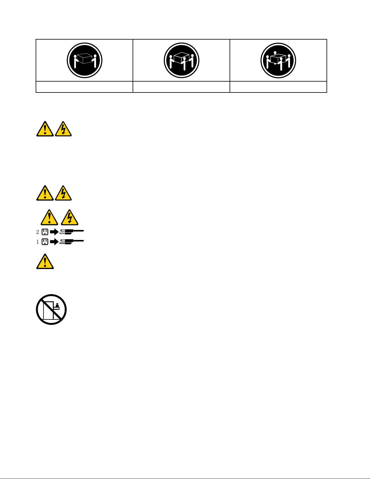
≥18 kg(37 lbs) ≥32 kg(70.5 lbs) ≥55 kg(121.2 lbs)
CAUTION:
Use safe practices when lifting.
CAUTION:
The power control button on the device and the power switch on the power supply do not turn off the
electrical current supplied to the device. The device also might have more than one power cord. To
remove all electrical current from the device, ensure that all power cords are disconnected from the
power source.
CAUTION:
Do not place any object weighing more than 82 kg (180 lbs.) on top of rack-mounted devices.
8 ideacentre 310S Series Hardware Maintenance Manual

Chapter 3. General information
This chapter provides general information that applies to all machine types supported by this publication.
Specifications
This section lists the physical specifications for your computer.
This section lists the physical specifications for your computer.
Type ideacentre 310S
This section lists the physical specifications.
Environment
Air temperature:
Operating: 10° to 35°C
Transit: -20° to 55°C
Humidity:
Operating: 35% to 80%
Transit: 20% to 90% (40°C)
Altitude: 86KPa to 106KPa
Electrical input:
Input voltage: 90V-264V(AC)
Input frequency: 47Hz-63Hz
© Copyright Lenovo 2016 9

10 ideacentre 310S Series Hardware Maintenance Manual

Chapter 4. General Checkout
Attention: The drives in the computer you are servicing might have been rearranged or the drive startup
sequence changed. Be extremely careful during write operations such as copying, saving, or formatting.
Data or programs can be overwritten if you select an incorrect drive.
General error messages appear if a problem or conflict is found by an application program, the operating
system, or both. For an explanation of these messages, refer to the information supplied with that software
package.
Use the following procedure to help determine the cause of the problem:
1. Power-off the computer and all external devices.
2. Check all cables and power cords.
3. Set all display controls to the middle position.
4. Power-on all external devices.
5. Power-on the computer.
• Look for displayed error codes
• Look for readable instructions or a main menu on the display.
If you did not receive the correct response, proceed to step 6.
If you do receive the correct response, proceed to step 7.
6. Look at the following conditions and follow the instructions:
• If the computer displays a POST error, go to “POST error codes”.
• If the computer hangs and no error is displayed, continue at step 7.
7. If the test stops and you cannot continue, replace the last device tested.
© Copyright Lenovo 2016 11

12 ideacentre 310S Series Hardware Maintenance Manual

Chapter 5. Using the Setup Utility
The Setup Utility program is used to view and change the configuration settings of your computer, regardless
of which operating system you are using. However, the operating-system settings might override any similar
settings in the Setup Utility program.
Starting the Lenovo BIOS Setup Utility program
To start the Lenovo BIOS Setup Utility program, do the following:
1. If your computer is already on when you start this procedure, shut down the operating system and turn
off the computer.
2. Press and hold the F1 key then turn on the computer. When the Lenovo BIOS Setup Utility program is
displayed, release the F1 key.
Note: If a Power-On Password or an Administrator Password has been set, the Setup Utility program menu
is not displayed until you type your password. For more information, see “Using passwords.”
Viewing and changing settings
System configuration options are listed in the Lenovo BIOS Setup Utility program menu. To view or change
settings, see “Starting the Setup Utility program.”
You must use the keyboard when using the Lenovo BIOS Setup Utility menu. The keys used to perform
various tasks are displayed on the bottom of each screen.
Using passwords
You can use the Lenovo BIOS Setup Utility program to set passwords to prevent unauthorized persons from
gaining access to your computer and data. See “Starting the Setup Utility program.” The following types of
passwords are available:
• Set Administrator Password
• Set Power-On Password
You do not have to set any passwords to use your computer. However, if you decide to set passwords, read
the following sections.
Password considerations
A password can be any combination of letters and numbers up to 16 character (a-z, and 0-9). For security
reasons, it is a good idea to use a strong password that cannot be easily compromised. We suggest that
passwords should follow these rules:
• Strong passwords contain 7-16 characters, combine letters and numbers.
• Do not use your name or your user name.
• Do not use a common word or a common name.
• Be significantly different from your previous password.
Attention: Administrator and Power-On passwords are not case sensitive
© Copyright Lenovo 2016 13

Administrator Password
Setting an Administrator Password deters unauthorized persons from changing configuration settings. You
might want to set an Administrator Password if you are responsible for maintaining the settings of several
computers.
After you set an Administrator Password, a password prompt is displayed every time you access the Lenovo
BIOS Setup Utility program.
If both the Administrator and Power-On Password are set, you can type either password. However, you must
use your Administrator Password to change any configuration settings.
Setting, changing, or deleting an Administrator password
To set an Administrator Password, do the following:
Note: A password can be any combination of letters and numbers up to 16 character (a-z, and 0-9). For
more information, see “Password considerations” on page 13.
1. Start the Lenovo BIOS Setup Utility program (see “Starting the Lenovo BIOS Setup Utility program” on
page 13).
2. From the Security menu, select Set Administrator Password and press the Enter key.
3. The password dialog box will be displayed. Type the password then press the Enter key.
4. Re-type the password to confirm, then press the Enter key. If you type the password correctly, the
password will be installed.
To change an Administrator Password, do the following:
1. Start the Lenovo BIOS Setup Utility program (see “Starting the Lenovo BIOS Setup Utility program” on
page 13).
2. From the Security menu, select Set Administrator Password and press the Enter key.
3. The password dialog box will be displayed. Type the current password then press Enter key.
4. Type the new password, then press Enter key. Re-type the password to confirm the new password, if
you type the new password correctly, the new password will be installed. A Setup Notice will display that
changes have been saved.
To delete a previously set Administrator Password, do the following :
1. From the Security menu, select Set Administrator Password and press the Enter key.
2. The password dialog box will be displayed. Type the current password and press the Enter key.
3. To delete an Administrator Password, Enter blank fields for each new password line item. A setup
notice will display that changes have been saved.
4. Return to the Lenovo BIOS Setup Utility program menu and select the Exit option.
5. Select Save changes and Exit from the menu.
Power-On Password
When a Power-On Password is set, you cannot start the Lenovo BIOS Setup Utility program until a valid
password is typed from the keyboard.
Setting, changing, or deleting a Power-On Password
14
ideacentre 310S Series Hardware Maintenance Manual

Note: A password can be any combination of letters and numbers up to 16 character (a-z, and 0-9).
To set a Power-On Password, do the following:
1. Start the Lenovo BIOS Setup Utility program (See ”Starting the Lenovo BIOS Setup Utility program” on
page 13.)
2. From the Security menu, select Set Power-On Password and press the Enter key.
3. The password dialog box will be displayed. Type the password, and press the Enter key.
4. Re-type the password to confirm, if you type the password correctly, the password will be installed.
To change a Power-On Password, do the following:
1. Start the Lenovo BIOS Setup Utility program (See ”Starting the Lenovo BIOS Setup Utility program” on
page 13.)
2. From the Security menu, select Set Power-On Password and press the Enter key.
3. The password dialog box will be displayed. Type the current password then press the Enter key.
4. Type the new password, then press the Enter key. Re-type the password to confirm the new password,
if you type the new password correctly, the new password will be installed. A setup notice will display
that changes have been saved.
To delete a previously set Power-On Password, do the following :
1. From the Security menu, select Set Power-On Password and press the Enter key.
2. The password dialog box will be displayed. Type the current password and press the Enter key.
3. To delete the Power-On Password, Enter blank fields for each new password line item. A setup notice
will display that changes have been saved.
4. Return to the Lenovo BIOS Setup Utility program menu and select the Exit option.
5. Select Save changes and Exit from the menu.
Enabling or disabling a device
The Devices options is used to enable or disable user access to the following devices:
USB Functions Select whether to enable or disable USB (Universal Serial
Bus) functions. If the functions are disabled, no USB
devices can be used.
ATA Drive Setup Select IDE or ACHI mode. Device driver support is
required for ACHI mode. Depending on how the hard disk
image was installed, changing this setting may prevent
the system from booting.
Onboard Audio Controller Select whether to enable or disable the Onboard Audio
Controller, when feature is set to Disabled all devices
connected to the audio connectors (e.g. a headphone or a
microphone) are disabled and can’t be used.
Onboard Ethernet Controller or Boot Agent Select whether to enable or disable Onboard Ethernet
Controller, or select whether to enable or disable load
onboard PXE (Preboot Execution Environment), or
SMC (Secure Managed Client). This feature will allow
the computer to boot from a server image.
To enable or disable a device, do the following:
Chapter 5. Using the Setup Utility 15

1. Start the Setup Utility program (see “Starting the Setup Utility program” on page 13).
2. From the Setup Utility program menu, select Devices.
3. Select:
USB Setup press the Enter key, and then select USB Functions.
ATA Device Setup press the Enter key. Select Configure SATA as, press the Enter key and then
select SATA mode.
Audio Setup press the Enter key, and then select Onboard Audio Controller.
Network Setup press the Enter key, then select Onboard Ethernet Support or Boot Agent.
4. Select Disabled or Enabled and press the Enter key.
5. Return to the Lenovo BIOS Setup Utility program menu and select the Exit option.
6. Select Save changes and Exit from the menu.
Note: If you do not want to save the settings, select Discard changes and Exit from the menu.
Selecting a startup device
If your computer does not boot from a device such as the CD/DVD-ROM drive disk or hard disk as expected,
follow one of the procedures below.
Selecting a temporary startup device
Use this procedure to startup from any boot device.
Note: Not all CDs, DVDs or hard disk drives are bootable.
1. Turn off your computer.
2. Press and hold the F12 key then turn on the computer. When the Startup Device Menu appears,
release the F12 key.
Note: If the Startup Device Menu does not display using these steps, repeatedly press and release the
F12 key rather than keeping it pressed when turning on the computer.
3. Use ↑ and ↓ arrows to select the desired startup device from the Startup Device Menu and press the
Enter key to begin.
Note: Selecting a startup device from the Startup Device Menu does not permanently change the
startup sequence.
Selecting or changing the startup device sequence
To view or permanently change the configured startup device sequence, do the following:
1. Start the Lenovo BIOS Setup Utility program (see “Starting the Lenovo BIOS Setup Utility program” on
page 13).
2. From the Lenovo BIOS Setup Utility program main menu, select the Startup option.
3. Press the Enter key, and select the devices for the Primary Boot Sequence. Read the information
displayed on the right side of the screen.
4. Use ↑ and ↓ arrows to select a device. Use the <+> or <-> keys to move a device up or down. Use the
<×> key to exclude the device from or include the device in the boot sequence.
5. Return to the Lenovo BIOS Setup Utility program menu and select the Exit option.
6. Select Save changes and Exit from the menu.
16
ideacentre 310S Series Hardware Maintenance Manual
 Loading...