

Lenovo HS23 Installation And User Manual

LenovoBladeCenterHS23Types7875and
1929
InstallationandUser’sGuide
MachineType:Types7875and1929

Note
Before using this information and the product it supports, read the general information in
“Notices” on page 77, the Warranty Information document, and the IBM Safety Information and the
Environmental Notices and User Guide documents on the IBM Documentation CD.
The most recent version of this document is available at http://www.ibm.com/supportportal/ .
Fourth Edition (December 2013)
© Copyright IBM Corporation 2013.
US Government Users Restricted Rights – Use, duplication or disclosure restricted by GSA ADP Schedule Contract
with IBM Corp.

Contents
Safety ............... v
Safety statements ............ vii
Chapter 1. Introduction ........ 1
Related documentation ........... 3
The IBM Documentation CD ......... 4
Hardware and software requirements ..... 4
Using the Documentation Browser ...... 4
Notices and statements in this document ..... 5
Features and specifications.......... 6
What your blade server offers ........ 8
Reliability, availability, and serviceability features .. 9
Major components of the blade server ..... 10
Chapter 2. Power, controls, and
indicators ............. 11
Blade server controls and LEDs........ 11
Turning on the blade server ........ 14
Turning off the blade server ........ 14
Blade server connectors ......... 15
Chapter 3. Installing options ..... 17
Installation guidelines ........... 17
System reliability guidelines ........ 18
Handling static-sensitive devices ...... 18
Instructions for IBM Business Partners .... 19
How to send DSA data to IBM ....... 19
Removing the blade server from the BladeCenter
unit ................. 20
Removing the blade server cover ....... 21
Installing an optional expansion unit ...... 22
Removing an optional expansion unit ..... 24
Installing a hot-swap storage drive ...... 25
Removing a hot-swap storage drive ...... 26
Installing a memory module......... 27
Removing a memory module ........ 30
Installing a microprocessor and heat sink .... 31
Thermal grease ............. 37
Installing a USB Flash key ......... 38
I/O expansion cards ........... 39
Installing a horizontal-compact-form-factor
expansion card ............ 39
Removing a horizontal-compact-form-factor
expansion card ............ 40
Installing a CIOv-form-factor expansion card .. 41
Removing a CIOv-form-factor expansion card .. 42
Installing a 10Gb interposer card ...... 43
Removing a 10Gb interposer card ...... 44
Completing the installation ......... 45
Installing the blade server cover ...... 45
Installing the blade server in a BladeCenter unit 47
Updating the blade server configuration .... 49
Input/output connectors and devices ...... 49
Chapter 4. Configuring the blade server 51
Using the Setup utility........... 52
Setup utility menu ........... 52
Using passwords ........... 56
Using the ServerGuide Setup and Installation CD . 56
ServerGuide features .......... 57
Setup and configuration overview ...... 57
Typical operating-system installation ..... 58
Installing the operating system without using
ServerGuide ............. 58
Setting the PXE boot protocol using the Setup utility 59
Updating firmware and device drivers ..... 60
Configuring UEFI compatible devices ..... 61
Configuring the Gigabit Ethernet controller.... 61
Configuring a RAID array ......... 62
Using the LSI Configuration Utility program ... 62
Using LAN over USB to interface the IMM2 ... 63
Potential conflicts with the LAN over USB
interface .............. 63
Resolving conflicts with the IMM2 LAN over
USB interface ............. 63
Configuring the LAN over USB interface
manually .............. 64
Chapter 5. Installing the operating
system............... 67
Using the ServerGuide Setup and Installation CD to
install the operating system ......... 67
Using RDM to install the operating system .... 68
Downloading installation instructions ..... 68
Chapter 6. Solving problems ..... 69
Diagnostic tools overview ......... 69
ServerGuide problems........... 70
Appendix. Getting help and technical
assistance ............. 73
Before you call ............. 73
Using the documentation .......... 74
Getting help and information from the World Wide
Web ................. 74
How to send DSA data to IBM ........ 75
Creating a personalized support web page .... 75
Software service and support ........ 75
Hardware service and support ........ 76
IBM Taiwan product service ......... 76
Notices .............. 77
Trademarks .............. 78
Important notes ............. 78
Particulate contamination.......... 79
Documentation format........... 80
Telecommunication regulatory statement .... 81
Electronic emission notices ......... 81
© Copyright IBM Corp. 2013 iii

Federal Communications Commission (FCC)
statement .............. 81
Industry Canada Class A emission compliance
statement .............. 82
Avis de conformité à la réglementation
d'Industrie Canada ........... 82
Australia and New Zealand Class A statement . 82
European Union EMC Directive conformance
statement .............. 82
Germany Class A statement ........ 83
Japan VCCI Class A statement ....... 84
Japan Electronics and Information Technology
Industries Association (JEITA) statement.... 84
Korea Communications Commission (KCC)
statement .............. 84
Russia Electromagnetic Interference (EMI) Class
A statement ............. 85
People's Republic of China Class A electronic
emission statement ........... 85
Taiwan Class A compliance statement .... 85
Index ............... 87
iv BladeCenter HS23 Types 7875 and 1929: Installation and User's Guide
Safety
Before installing this product, read the Safety Information.
Antes de instalar este produto, leia as Informações de Segurança.
Læs sikkerhedsforskrifterne, før du installerer dette produkt.
Lees voordat u dit product installeert eerst de veiligheidsvoorschriften.
Ennen kuin asennat tämän tuotteen, lue turvaohjeet kohdasta Safety Information.
Avant d'installer ce produit, lisez les consignes de sécurité.
Vor der Installation dieses Produkts die Sicherheitshinweise lesen.
Prima di installare questo prodotto, leggere le Informazioni sulla Sicurezza.
© Copyright IBM Corp. 2013 v

Les sikkerhetsinformasjonen (Safety Information) før du installerer dette produktet.
Antes de instalar este produto, leia as Informações sobre Segurança.
Antes de instalar este producto, lea la información de seguridad.
Läs säkerhetsinformationen innan du installerar den här produkten.
vi BladeCenter HS23 Types 7875 and 1929: Installation and User's Guide
Safety statements
These statements provide the caution and danger information that is used in this
documentation.
Important:
Each caution and danger statement in this documentation is labeled with a
number. This number is used to cross reference an English-language caution or
danger statement with translated versions of the caution or danger statement in
the Safety Information document.
For example, if a caution statement is labeled Statement 1, translations for that
caution statement are in the Safety Information document under Statement 1.
Be sure to read all caution and danger statements in this documentation before you
perform the procedures. Read any additional safety information that comes with
your system or optional device before you install the device.
Statement 1
DANGER
Electrical current from power, telephone, and communication cables is
hazardous.
To avoid a shock hazard:
v Do not connect or disconnect any cables or perform installation,
maintenance, or reconfiguration of this product during an electrical storm.
v Connect all power cords to a properly wired and grounded electrical outlet.
v Connect to properly wired outlets any equipment that will be attached to
this product.
v When possible, use one hand only to connect or disconnect signal cables.
v Never turn on any equipment when there is evidence of fire, water, or
structural damage.
v Disconnect the attached power cords, telecommunications systems,
networks, and modems before you open the device covers, unless
instructed otherwise in the installation and configuration procedures.
v Connect and disconnect cables as described in the following table when
installing, moving, or opening covers on this product or attached devices.
Safety vii
To Connect: To Disconnect:
1. Turn everything OFF.
2. First, attach all cables to devices.
3. Attach signal cables to connectors.
4. Attach power cords to outlet.
5. Turn device ON.
1. Turn everything OFF.
2. First, remove power cords from outlet.
3. Remove signal cables from connectors.
4. Remove all cables from devices.
Statement 2
CAUTION:
When replacing the lithium battery, use only IBM®Part Number 33F8354 or an
equivalent type battery recommended by the manufacturer. If your system has a
module containing a lithium battery, replace it only with the same module type
made by the same manufacturer. The battery contains lithium and can explode if
not properly used, handled, or disposed of.
Do not:
v Throw or immerse into water
v Heat to more than 100°C (212°F)
v Repair or disassemble
Dispose of the battery as required by local ordinances or regulations.
Statement 3
CAUTION:
When laser products (such as CD-ROMs, DVD drives, fiber optic devices, or
transmitters) are installed, note the following:
v Do not remove the covers. Removing the covers of the laser product could
result in exposure to hazardous laser radiation. There are no serviceable parts
inside the device.
v Use of controls or adjustments or performance of procedures other than those
specified herein might result in hazardous radiation exposure.
viii BladeCenter HS23 Types 7875 and 1929: Installation and User's Guide
DANGER
Some laser products contain an embedded Class 3A or Class 3B laser diode.
Note the following.
Laser radiation when open. Do not stare into the beam, do not view directly
with optical instruments, and avoid direct exposure to the beam.
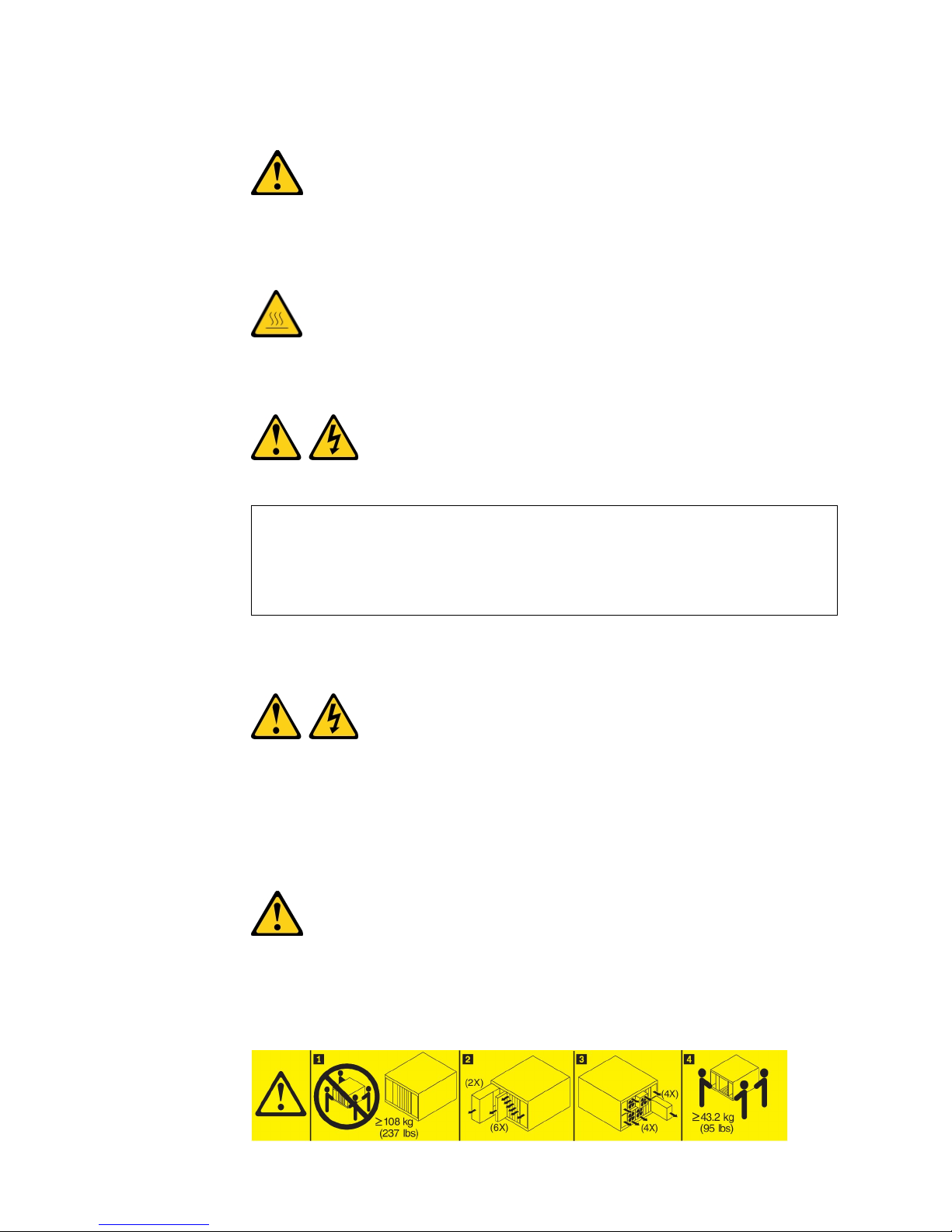
Statement 4
CAUTION:
Use safe practices when lifting.
≥ 18 kg (39.7 lb) ≥ 32 kg (70.5 lb) ≥ 55 kg (121.2 lb)
Statement 8
CAUTION:
Never remove the cover on a power supply or any part that has the following
label attached.
Hazardous voltage, current, and energy levels are present inside any component
that has this label attached. There are no serviceable parts inside these
components. If you suspect a problem with one of these parts, contact a service
technician.
Safety ix
Statement 12
CAUTION:
The following label indicates a hot surface nearby.
Statement 13
DANGER
Overloading a branch circuit is potentially a fire hazard and a shock hazard
under certain conditions. To avoid these hazards, ensure that your system
electrical requirements do not exceed branch circuit protection requirements.
Refer to the information that is provided with your device for electrical
specifications.
Statement 21
CAUTION:
Hazardous energy is present when the blade is connected to the power source.
Always replace the blade cover before installing the blade.
Statement 32
CAUTION:
To avoid personal injury, before lifting the unit, remove all the blades, power
supplies, and removable modules to reduce the weight.
x BladeCenter HS23 Types 7875 and 1929: Installation and User's Guide
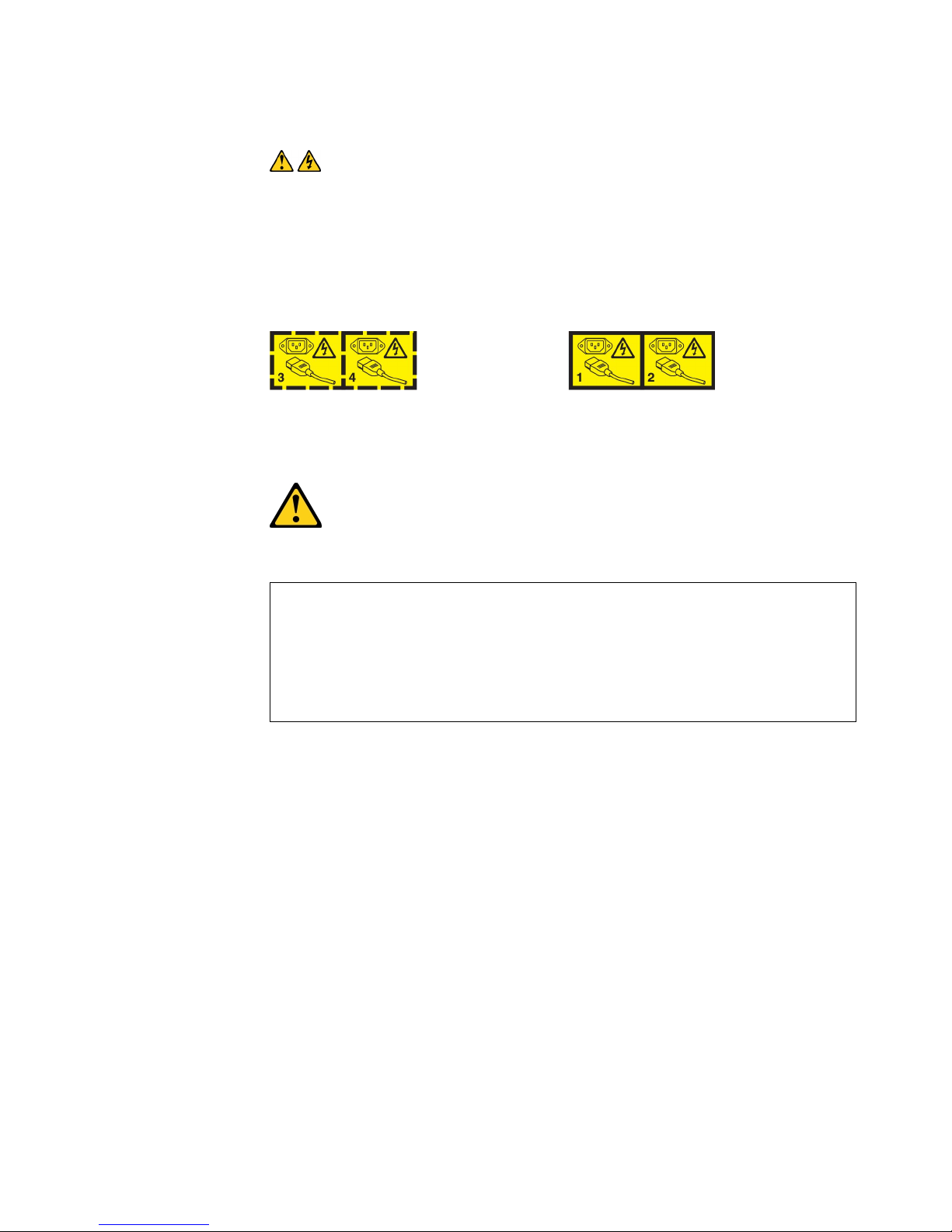
Statement 33
CAUTION:
This device does not provide a power control button. Removing power supply
modules or turning off the server blades does not turn off the electrical current
supplied to the device. The device also might have more than one power cord.
To remove all electrical current from the device, ensure that all power cords are
disconnected from the power source.
Rack Safety Information, Statement 2
DANGER
v Always lower the leveling pads on the rack cabinet.
v Always install stabilizer brackets on the rack cabinet.
v Always install servers and optional devices starting from the bottom of the
rack cabinet.
v Always install the heaviest devices in the bottom of the rack cabinet.
UL regulatory information
This device is for use only with Listed .
Safety xi

xii BladeCenter HS23 Types 7875 and 1929: Installation and User's Guide

Chapter 1. Introduction
The IBM BladeCenter HS23 Types 7875 and 1929 blade server is compatible with
IBM BladeCenter units. This high density, high performance, single-wide blade
server is ideally suited for medium and large businesses. The IBM BladeCenter
HS23 blade server supports up to two multi-core Intel Xeon microprocessors and
has sixteen memory-module slots, two hot-swappable storage-device bays, one
Horizontal-compact-form-factor (CFFh) expansion card connector, one
Vertical-combination-I/O (CIOv) connector, and one internal USB connector.
Note: Unless otherwise stated, references to the BladeCenter unit apply to all
BladeCenter unit types.
This Installation and User's Guide provides information about:
v Setting up the blade server
v Starting and configuring the blade server
v Installing hardware options
v Installing the operating system
v Performing basic troubleshooting of the blade server
Packaged with this document are software CDs that help you to configure
hardware, install device drivers, and install the operating system.
To download the latest device drivers, go to http://www.ibm.com/supportportal/
.
The blade server comes with a limited warranty. For information about the terms
of the warranty and getting service and assistance, see the Warranty Information
document for your blade server. You can obtain up-to-date information about the
blade server at http://www.ibm.com/systems/bladecenter/.
If firmware and documentation updates are available, you can download them
from the IBM website. The blade server might have features that are not described
in the documentation that comes with the blade server, and the documentation
might be updated occasionally to include information about those features, or
technical updates might be available to provide additional information that is not
included in the blade server documentation.
To check for updates, go to http://www.ibm.com/supportportal/ .
You can subscribe to information updates specific to your blade server at
http://www.ibm.com/support/mysupport/ .
Note: The illustrations in this document might differ slightly from the hardware.
The following illustration shows an IBM BladeCenter HS23 blade server.
© Copyright IBM Corp. 2013 1
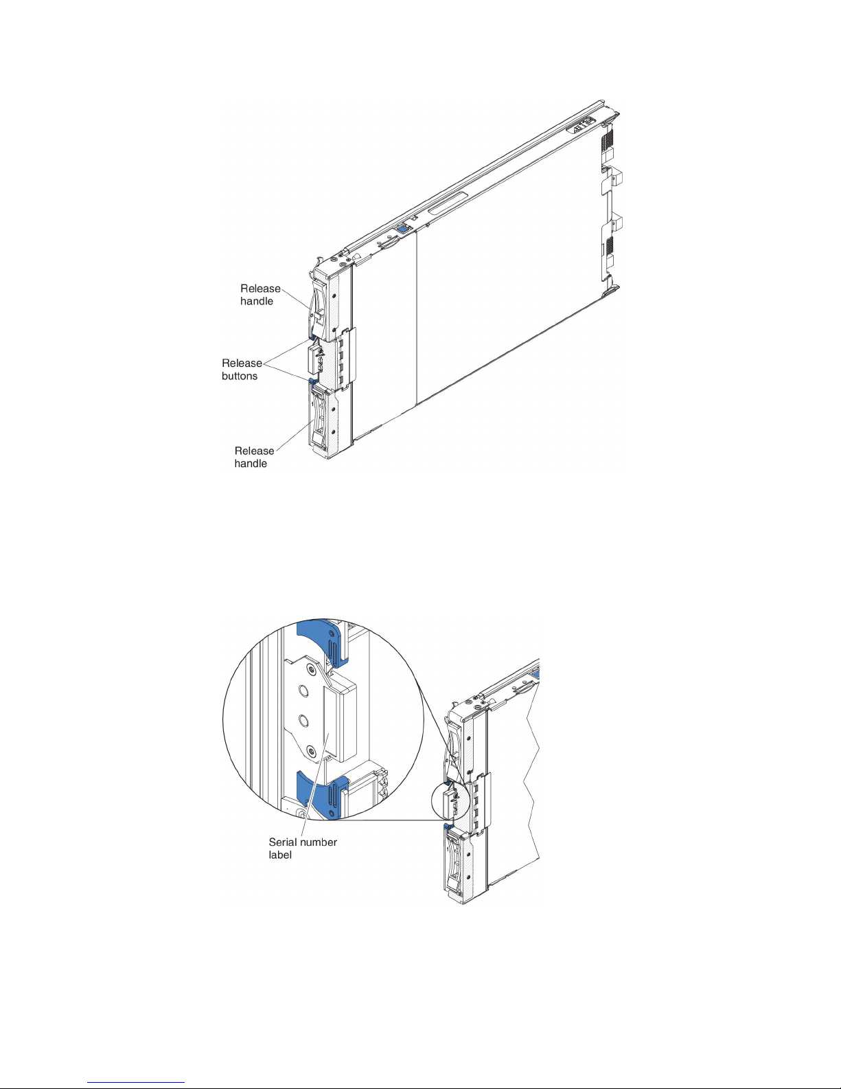
The model number and serial number are on the ID label on the side of the control
panel on the front of the blade server, and on a label on the side of the blade
server that is visible when the blade server is not in the BladeCenter unit.
Important: Do not place the label on the blade server itself or in any way block
the ventilation holes on the blade server.
A set of blank labels for your blade server comes with the BladeCenter unit. When
you install the blade server in the BladeCenter unit, write identifying information
on a label and place the label on the BladeCenter unit bezel. See the
documentation for your BladeCenter unit for recommended label placement.
2 BladeCenter HS23 Types 7875 and 1929: Installation and User's Guide

Related documentation
Use this information to identify and locate related blade server documentation.
This Installation and User's Guide contains general information about the blade
server, including how to install supported optional devices and how to configure
the blade server. The following documentation is also available:
v Safety Information
This document contains translated caution and danger statements. Each caution
and danger statement that appears in the documentation has a number that you
can use to locate the corresponding statement in your language in the Safety
Information document.
v Warranty Information
This document contains information about the terms of the warranty.
v Environmental Notices and User Guide
This document contains translated environmental notices.
v Integrated Management Module II User's Guide
This document explains how to use the functions of the IMM2 that is installed in
an IBM server. The IMM2 works with IBM UEFI firmware to provide
systems-management capability for System x®servers and blade servers.
v Advanced Management Module Messages Guide
This document provides a complete list of all non-device specific events and
recommended actions, sorted by event ID. Device specific event information is in
the documentation for the device.
v Advanced Management Module Command-Line Interface Reference Guide
This document explains how to use the advanced management module
command-line interface (CLI) to directly access the BladeCenter management
functions. The command-line interface also provides access to the text-console
command prompt on each blade server through a Serial over LAN (SOL)
connection.
v Advanced Management Module Messages Guide
This document provides a complete list of all non-device-specific events and
recommended actions, sorted by event ID. For event information that is specific
to this blade server, see the Problem Determination and Service Guide for more
information.
v Safety Labels
This document is in PDF on the IBM System x Documentation CD. This document
provides the Simplified Chinese, Mongolian, Tibetan, Uygur, and Zhuang
translated versions of the product safety labels.
In addition to the documentation in this library, be sure to review the Planning and
Installation Guide for your BladeCenter unit for information to help you prepare for
system installation and configuration.
To check for updated documentation and technical updates, go to
http://www.ibm.com/supportportal/ .
Chapter 1. Introduction 3

The IBM Documentation CD
Use the IBM Documentation CD to access the blade server documentation in PDF
format.
The IBM Documentation CD contains documentation for your blade server in
Portable Document Format (PDF) and includes the IBM Documentation Browser to
help you find information quickly.
You can run the IBM Documentation CD on any computer that meets the hardware
and software requirements.
Hardware and software requirements
Use this information to determine the minimum hardware and software
requirements for the blade server.
The IBM Documentation CD requires the following minimum hardware and
software:
v Microsoft Windows XP, Windows 2000, or Red Hat Enterprise Linux 5 Server
v 100 MHz microprocessor
v 32 MB of RAM
v Adobe Acrobat Reader 3.0 (or later) or xpdf, which comes with Linux operating
systems
Using the Documentation Browser
Use these instructions to start the Documentation Browser.
Use the Documentation Browser to browse the contents of the CD, read brief
descriptions of the documents, and view documents, using Adobe Acrobat Reader
or xpdf. The Documentation Browser automatically detects the regional settings in
use in your system and displays the documents in the language for that region (if
available). If a document is not available in the language for that region, the
English-language version is displayed.
Use one of the following procedures to start the Documentation Browser:
v If Autostart is enabled, insert the CD into the CD drive. The Documentation
Browser starts automatically.
v If Autostart is disabled or is not enabled for all users, use one of the following
procedures:
– If you are using a Windows operating system, insert the CD into the CD or
DVD drive and click Start → Run. In the Open field, type
e:\win32.bat
where e is the drive letter of the CD or DVD drive, and click OK.
– If you are using Red Hat Linux, insert the CD into the CD or DVD drive;
then, run the following command from the /mnt/cdrom directory:
sh runlinux.sh
Select your blade server from the Product menu. The Available Topics list displays
all the documents for your blade server. Some documents might be in folders. A
plus sign (+) indicates each folder or document that has additional documents
under it. Click the plus sign to display the additional documents.
4 BladeCenter HS23 Types 7875 and 1929: Installation and User's Guide

When you select a document, a description of the document is displayed under
Topic Description. To select more than one document, press and hold the Ctrl key
while you select the documents. Click View Book to view the selected document
or documents in Acrobat Reader or xpdf. If you selected more than one document,
all the selected documents are opened in Acrobat Reader or xpdf.
To search all the documents, type a word or word string in the Search field and
click Search. The documents in which the word or word string appears are listed
in order of the most occurrences. Click a document to view it, and press Crtl+F to
use the Acrobat search function, or press Alt+F to use the xpdf search function
within the document.
Click Help for detailed information about using the Documentation Browser.
Notices and statements in this document
Use this information to understand the most common documentation notices and
statements and how they are used.
The caution and danger statements in this document are also in the multilingual
Safety Information document, which is on the IBM Documentation CD. Each
statement is numbered for reference to the corresponding statement in the Safety
Information document.
The following notices and statements are used in this document:
v Note: These notices provide important tips, guidance, or advice.
v Important: These notices provide information or advice that might help you
avoid inconvenient or problem situations.
v Attention: These notices indicate possible damage to programs, devices, or data.
An attention notice is placed just before the instruction or situation in which
damage might occur.
v Caution: These statements indicate situations that can be potentially hazardous
to you. A caution statement is placed just before the description of a potentially
hazardous procedure step or situation.
v Danger: These statements indicate situations that can be potentially lethal or
extremely hazardous to you. A danger statement is placed just before the
description of a potentially lethal or extremely hazardous procedure step or
situation.
Chapter 1. Introduction 5

Features and specifications
Use this table to view specific information about the blade server, such as blade
server hardware features and the dimensions of the blade server.
Notes:
1. Power, cooling, removable-media drives, external ports, and advanced system
management are provided by the BladeCenter unit.
2. The operating system in the blade server must provide USB support for the
blade server to recognize and use USB media drives and devices. The
BladeCenter unit uses USB for internal communications with these devices.
The following table is a summary of the features and specifications of the blade
server.
6 BladeCenter HS23 Types 7875 and 1929: Installation and User's Guide

Table 1. Features and specifications
Microprocessor: Supports up to two
multi-core Intel Xeon microprocessors.
Note: Use the Setup utility to
determine the type and speed of the
microprocessors in the blade server.
Memory:
v 16 dual inline memory module
(DIMM) connectors
v Type: Very Low Profile (VLP)
double-data rate (DDR3) DRAM.
Supports 4 GB, 8 GB, and 16 GB
DIMMs with up to 256 GB of total
memory on the system board
Integrated functions:
v Horizontal-compact-form-factor
(CFFh) expansion card interface
v Vertical-combination-I/O (CIOv)
expansion card interface
v Local service processor: Integrated
Management Module II (IMM2)
with Intelligent Platform
Management Interface (IPMI)
firmware
v Integrated Renesas SH7757 IMM2
video controller
v SAS controller
v Integrated keyboard/video/mouse
(cKVM) controller through IMM2
v Light path diagnostics
v RS-485 interface for communication
with the management module
v USB 2.0 for communication with
cKVM and removable media drives
(an external USB port is not
supported)
v Serial over LAN (SOL)
v Wake on LAN (WOL)
v Redundant buses for
communication with keyboard,
mouse, and removable media
drives
Predictive Failure Analysis (PFA)
alerts:
v Microprocessors
v Memory
v Storage drives
Electrical input: 12 V dc
Environment:
v Air temperature:
– Blade server on: 10°C to 35°C
(50°F to 95°F). Altitude: 0 m to
914.4 m (0 ft to 3000 ft)
– Blade server on: 10°C to 32°C
(50°F to 89.6°F). Altitude: 914.4
m to 2133.6 m (3000 ft to 7000
ft)
– Blade server off: 10°C to 43°C
(50°F to 109.4°F). Altitude: 914.4
m to 2133.6 m (3000 ft to 7000
ft)
– Blade server shipping: -40°C to
60°C (-40°F to 140°F)
v Humidity:
– Blade server on: 8% to 80%
– Blade server off: 8% to 80%
– Blade server storage: 5% to 80%
– Blade server shipment: 5% to
100%
v E5-2697 V2 and E5-2690 V2 will
reach their maximum operating
temperature and throttle at
ambient 31°C in Blade Center H
chassis, when being fully
exercised.
Drives: Supports up to two hot-swap,
small form factor (SFF) Serial Attached
SCSI (SAS) or Serial ATA (SATA)
storage drives
Size:
v Height: 24.5 cm (9.7 inches)
v Depth: 44.6 cm (17.6 inches)
v Width: 2.9 cm (1.14 inches)
v Maximum weight: 17.81 kg (39.25 lb)
NEBS Environment
v Air temperature:
– Blade server on: 5°C to 40°C (41°F
to 104°F). Altitude: -60 m to 1800
m (-197 ft to 6000 ft)
– Blade server on: 5°C to 30°C (41°F
to 86°F). Altitude: 1800 m to 4000
m (6000 ft to 13000 ft)
– Blade server off: -5°C to 55°C
(23°F to 131°F). Altitude: -60 m to
1800 m (-197 ft to 6000 ft)
– Blade server off: -5°C to 45°C
(23°F to 113°F). Altitude: 1800 m
to 4000 m (6000 ft to 13000 ft)
– Blade server storage: -40°C to
60°C (-40°F to 140°F)
v Humidity: 8% to 85%
v Particulate contamination:
Attention: Airborne particulates
and reactive gases acting alone or in
combination with other
environmental factors such as
humidity or temperature might pose
a risk to the server. For information
about the limits for particulates and
gases, see “Particulate
contamination” on page 79.
Chapter 1. Introduction 7

What your blade server offers
Your blade server offers features, such as, the Integrated Management Module II
(IMM2), storage disk drive support, IBM Enterprise X-Architecture, microprocessor
technology, integrated network support, I/O expansion, large system-memory
capacity, light path diagnostics, PCI Express, and power throttling.
v Integrated Management Module II (IMM2)
The integrated management module II (IMM2) combines service processor
functions, video controller, the remote presence, and blue-screen capture features
in a single chip. The IMM2 provides advanced service-processor control,
monitoring, and alerting function. If an environmental condition exceeds a
threshold or if a system component fails, the IMM2 lights LEDs to help you
diagnose the problem, records the error in the IMM2 system event log, and
alerts you to the problem.
Optionally, the IMM2 also provides a virtual presence capability for remote
systems management capabilities. The IMM2 provides remote systems
management through industry-standard interfaces:
– Common Information Model (CIM)
– Intelligent Platform Management Interface (IPMI) version 2.0
– Simple Network Management Protocol (SNMP) version 3.0
– Web browser
v Hard disk drive support
The blade server supports up to two 2.5-inch hot-swap SAS SFF hard disk
drives. You can implement RAID 0 or RAID 1 for the drives.
v IBM ServerGuide Setup and Installation CD
The ServerGuide Setup and Installation CD provides programs to help you set up
the blade server and install a Windows operating system. The ServerGuide
program detects installed optional hardware devices and provides the correct
configuration programs and device drivers. For more information about the
ServerGuide Setup and Installation CD, see “Using the ServerGuide Setup and
Installation CD” on page 56.
v Microprocessor technology
The blade server supports up to two Intel Xeon microprocessors. For more
information about supported microprocessors and their part numbers, see the
Problem Determination and Service Guide.
v Integrated network support
The integrated Emulex BE3 dual-port Gigabit Ethernet controller supports
connections to a 10 Mbps, 100 Mbps, or 1000 Mbps network through an
Ethernet-compatible switch module in the chassis. The controller also supports
Wake on LAN®technology.
The blade server has connectors on the system board for optional expansion
adapters for adding network communication capabilities to the blade server.
Depending on the model, you can install up to two I/O expansion adapters for
network support. This provides the flexibility to install expansion adapters that
support a variety of network communication technologies.
v I/O expansion
The blade server has connectors on the system board for optional expansion
cards for adding more network communication capabilities to the blade server.
v Large system-memory capacity
The blade server system board supports up to 256 GB of system memory. The
memory controller provides support for up to sixteen industry-standard
8 BladeCenter HS23 Types 7875 and 1929: Installation and User's Guide

registered ECC DDR3 on Very Low Profile (VLP) form factor DIMMs installed
on the system board. For the most current list of supported DIMMs, see the
ServerProven list at http://www.ibm.com/systems/info/x86servers/
serverproven/compat/us/.
v Light path diagnostics
Light path diagnostics provides light-emitting diodes (LEDs) to help you
diagnose problems. For more information, see Light path diagnosticsthe Problem
Determination and Service Guide.
v PCI Express
PCI Express is a serial interface that is used for chip-to-chip interconnect and
expansion adapter interconnect. With the blade expansion connector you can
add optional I/O and storage devices.
v Power throttling
Each blade server is powered by two Enterprise Voltage Regulator-Down
(EVRD) 12.0 voltage regulators. By enforcing a power policy known as
power-domain oversubscription, the BladeCenter unit can share the power load
between two power modules to ensure sufficient power for each device in the
BladeCenter unit. This policy is enforced when the initial power is applied to the
BladeCenter unit or when a blade server is inserted into the BladeCenter unit.
The following settings for this policy are available:
– Redundant without performance impact
– Redundant with performance impact
– Non-redundant
You can configure and monitor the power environment by using the Advanced
Management Module. For more information about configuring and using power
throttling, see the Advanced-Management-Module documentation or
http://www.ibm.com/supportportal/ .
Reliability, availability, and serviceability features
Reliability, availability, and serviceability features help to ensure the integrity of the
data that is stored in the blade server, the availability of the blade server when you
need it, and the ease with which you can diagnose and correct problems.
Three of the most important features in server design are reliability, availability,
and serviceability (RAS). These RAS features help to ensure the integrity of the
data that is stored in the blade server, the availability of the blade server when you
need it, and the ease with which you can diagnose and correct problems.
The blade server has the following RAS features:
v Advanced Configuration and Power Interface (ACPI)
v Built-in diagnostics using DSA Preboot, which is stored in integrated USB
memory
v Built-in monitoring for temperature, voltage, and hard disk drives
v Customer support center 24 hours per day, 7 days a week
v Customer upgrade of Flash ROM-resident code and diagnostics
v Customer-upgradeable Unified Extensible Firmware Interface (UEFI) code and
diagnostics
v ECC protected DDR3 memory
v ECC protection on the L2 cache
v Error codes and messages
1. Service availability will vary by country. Response time will vary depending on the number and nature of incoming calls.
1
Chapter 1. Introduction 9
v Hot-swap SAS storage drives
v Integrated Management Module (IMM)
v Light path diagnostics
v Memory parity testing
v Microprocessor built-in self-test (BIST) during power-on self-test (POST)
v Microprocessor serial number access
v PCI PMI 2.2
v POST
v Power policy 24-hour support center
v Processor presence detect
v ROM resident diagnostics
v Service processor that communicates with the Advanced Management Module to
enable remote blade server management
v System error logging
v Vital product data (VPD) on memory
v Wake on LAN capability
v Wake on PCI (PME) capability
v Wake on USB 2.0 capability
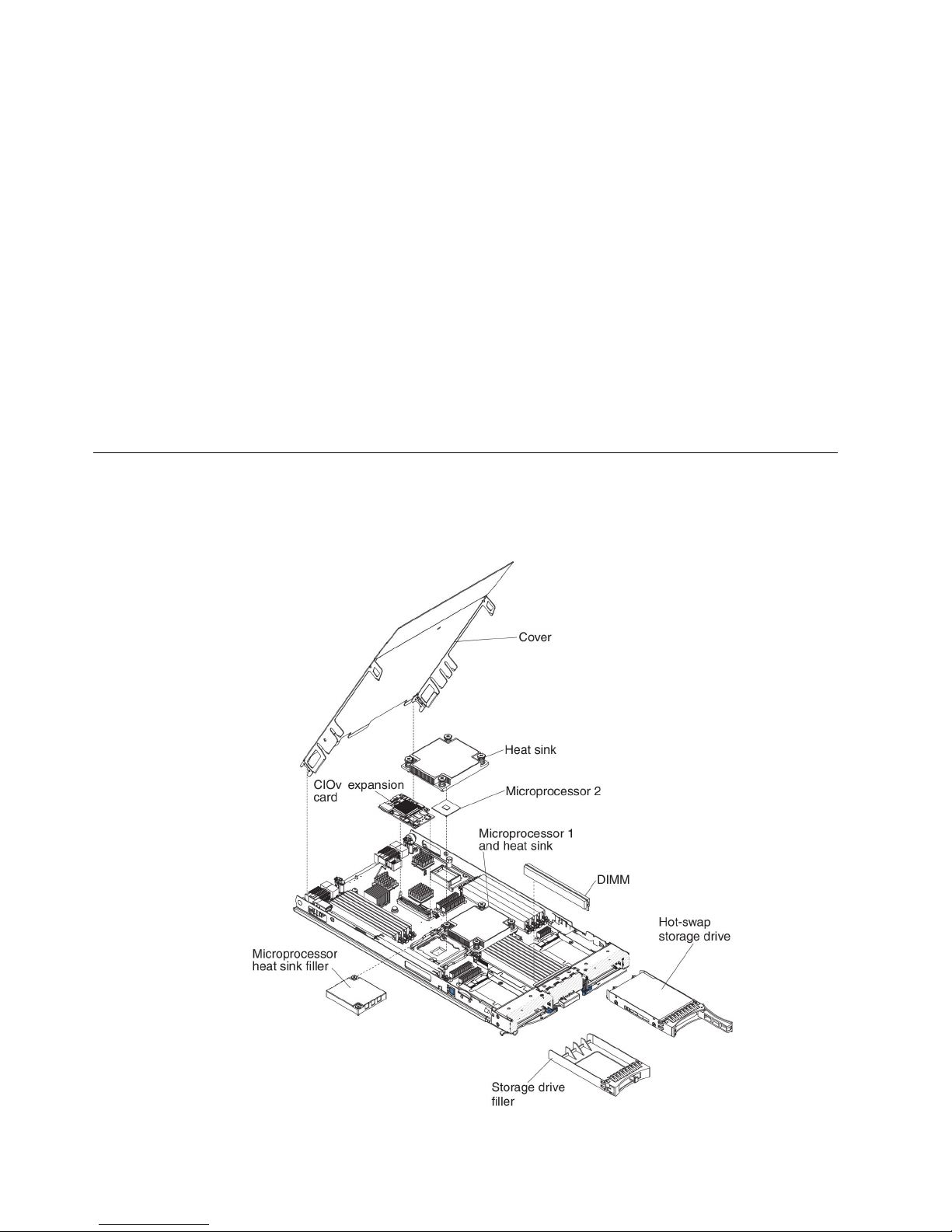
Major components of the blade server
Use this information to locate the major components on the blade server.
The following illustration shows the major components of the blade server.
10 BladeCenter HS23 Types 7875 and 1929: Installation and User's Guide
Chapter 2. Power, controls, and indicators
Use this information to view power features, turn on and turn off the blade server,
and view the functions of the controls and indicators.
Blade server controls and LEDs
Use this information for details about the controls and LEDs on the blade server.
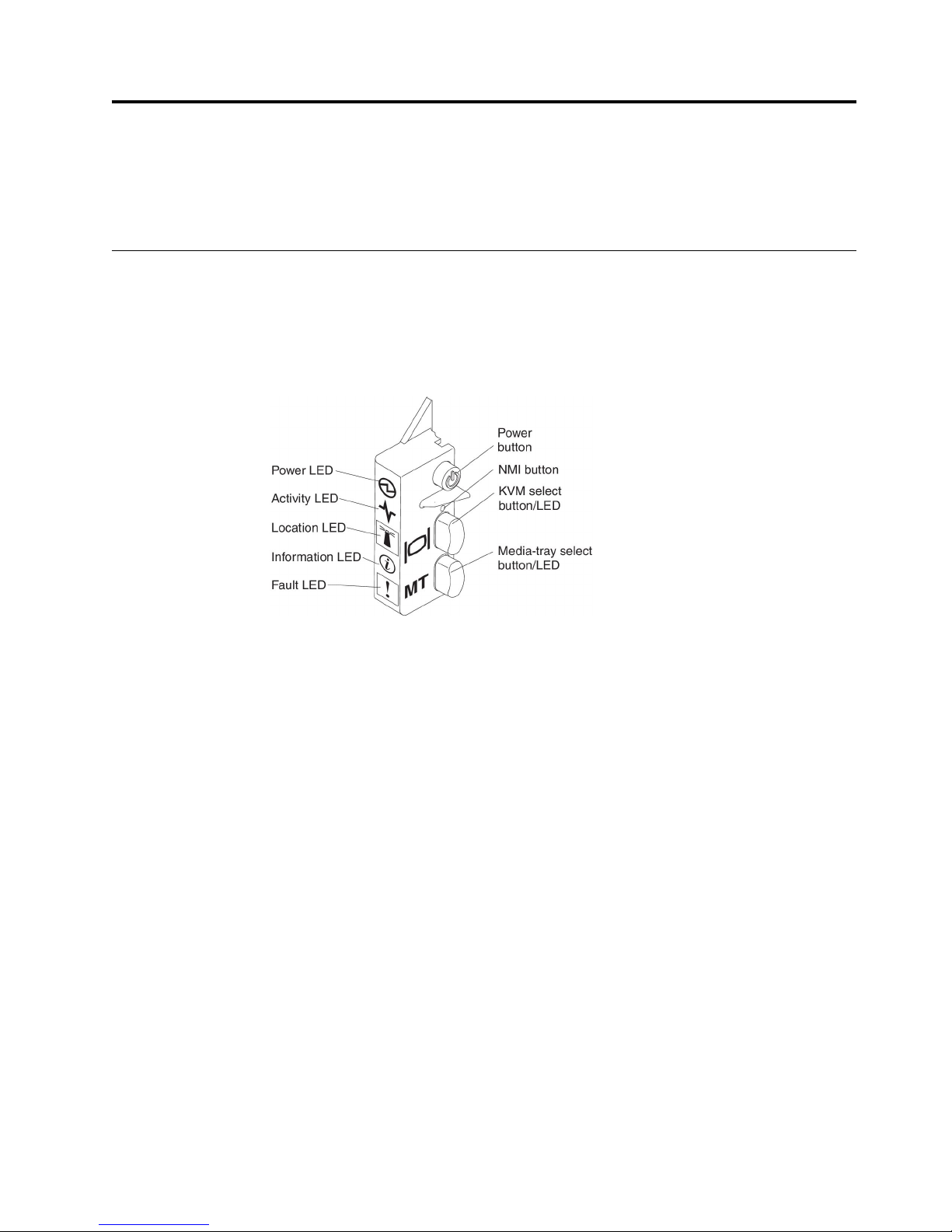
The following illustration identifies the buttons and information LEDs on the
blade-server control panel.
Power-on LED: This green LED indicates the power status of the blade server in
the following manner:
v Flashing rapidly: While the service processor in the blade server is initializing
and synchronizing with the management module, the power-on LED flashes
rapidly, and the power-control button on the blade server does not respond. This
process can take approximately two minutes after the blade server has been
installed. If the LED continues to flash rapidly, the blade server might not have
power permissions assigned to it through the Advanced Management Module
(AMM), the BladeCenter unit does not have enough power to turn on the blade
server, or the service processor (IMM2) on the blade server is not
communicating with the AMM.
v Flashing slowly: The blade server has power supplied and is ready to be turned
on.
v Lit continuously: The blade server has power and is turned on.
Activity LED: When this green LED is lit, it indicates that there is activity on the
external storage device or network.
Location LED: The system administrator can remotely turn on this blue LED to aid
in visually locating the blade server. When this LED is lit, the location LED on the
BladeCenter unit is also lit. The location LED can be turned off through the
Advanced-Management-Module Web interface. For more information about the
Advanced-Management-Module web interface, see http://www.ibm.com/systems/
management/.
© Copyright IBM Corp. 2013 11

Information LED: The Information LED is indicated by a lower case "i". When this
yellow LED is lit, it indicates that information about a system event in the blade
server has been placed in the Advanced-Management-Module event log. The
information LED can be turned off through the Advanced-Management-Module
CLI, SNMP, or web interface. For more information about the AdvancedManagement-Module web interface, see http://www.ibm.com/systems/
management/.
Fault LED: The Fault LED is indicated by an exclamation mark. When this yellow
LED is lit, it indicates that a system error has occurred in the blade server. The
blade-error LED turns off only after the error is corrected.
Power-control button: Press this button to turn on or turn off the blade server.
When the blade server is turned off, you can press and hold the power-control
button to light the LEDs of failing components in the blade server.
Note: The power-control button has effect only if local power control is enabled
for the blade server. Local power control is enabled and disabled through the
Advanced-Management-Module web interface.
NMI button (recessed): The nonmaskable interrupt (NMI) dumps the partition.
Use this recessed button only as directed by IBM Support.
Note: You can also send an NMI event to the selected blade server remotely using
the AMM. For more information, see the BladeCenter Advanced Management Module
User's Guide.
Keyboard/video/mouse (KVM) select button: Press this button to associate the
shared BladeCenter unit keyboard port, video port, and mouse port with the blade
server. The LED on this button flashes while the request is being processed and
then is lit when the ownership of the keyboard, video, and mouse has been
transferred to the blade server. It can take approximately 20 seconds to switch the
keyboard, video, and mouse control to the blade server.
Using a keyboard that is directly attached to the AMM, you can press keyboard
keys in the following sequence to switch KVM control between blade servers
instead of using the KVM select button:
NumLock NumLock blade_server_number Enter
blade_server_number is the two-digit number of the blade-server bay in which
the blade server is installed. A blade server that occupies more than one
blade-server bay is identified by the lowest bay number that it occupies.
If there is no response when you press the KVM select button, you can use the
Advanced-Management-Module web interface to determine whether local control
has been disabled on the blade server. See http://www.ibm.com/systems/
management/ for more information.
Notes:
1. The operating system in the blade server must provide USB support for the
blade server to recognize and use the keyboard and mouse, even if the
keyboard and mouse have PS/2-style connectors.
2. If you install a supported Microsoft Windows operating system on the blade
server while it is not the current owner of the keyboard, video, and mouse, a
delay of up to 1 minute occurs the first time that you switch the keyboard,
12 BladeCenter HS23 Types 7875 and 1929: Installation and User's Guide
video, and mouse to the blade server. All subsequent switching takes place in
the normal KVM switching time frame (up to 20 seconds).
Media-tray select button: Press this button to associate the shared BladeCenter
unit media tray (removable-media drives) with the blade server. The LED on the
button flashes while the request is being processed and then is lit when the
ownership of the media tray has been transferred to the blade server. It can take
approximately 20 seconds for the operating system in the blade server to recognize
the media tray.
If there is no response when you press the media-tray select button, you can use
the Advanced-Management-Module Web interface to determine whether local
control has been disabled on the blade server.
Note: The operating system in the blade server must provide USB support for the
blade server to recognize and use the removable-media drives.
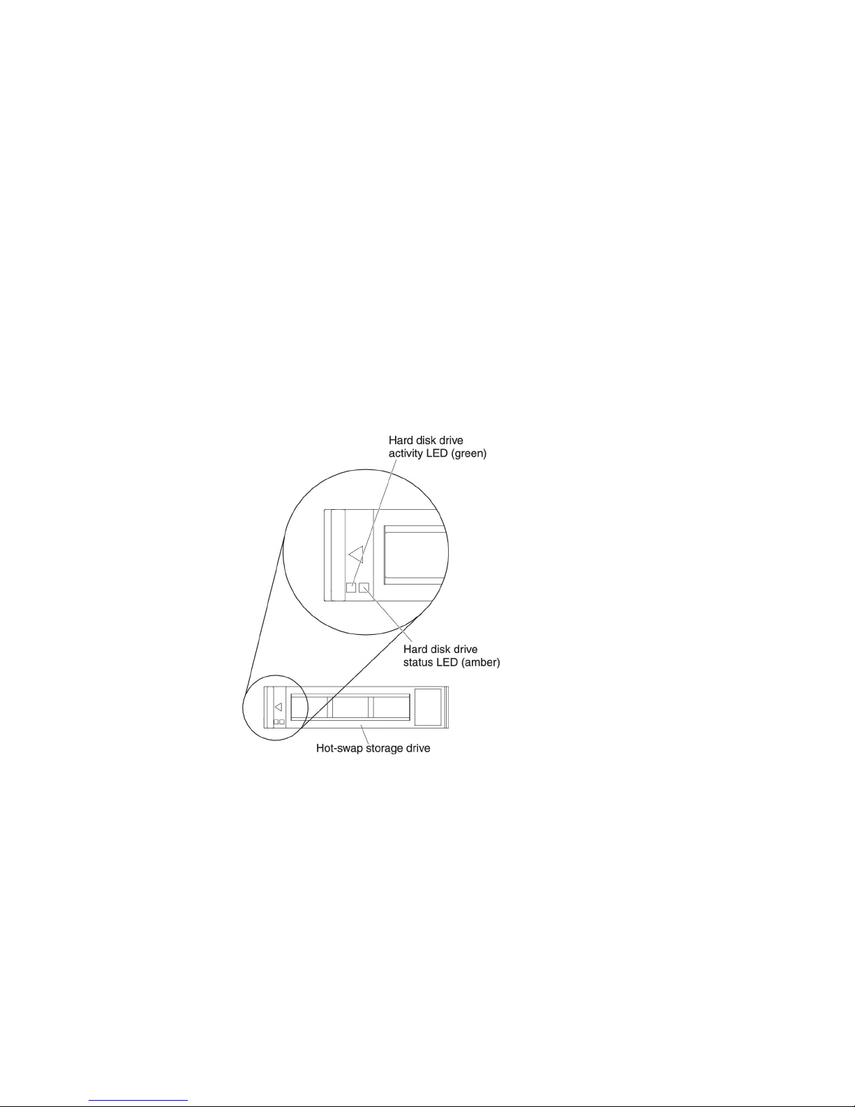
The following illustration identifies the information LEDs on the SAS hot-swap
hard disk drive.
Hard disk drive activity LED (green): When this green LED is lit, it indicates that
there is activity on the storage drive.
Hard disk drive status LED (yellow): When this yellow LED is lit, it indicates that
an error has occurred with the storage drive. The LED turns off only after the error
is corrected.
Chapter 2. Power, controls, and indicators 13

Turning on the blade server
Use this information to turn on the blade server.
After you connect the blade server to power through the BladeCenter unit, the
blade server can start in any of the following ways:
v You can press the power-control button on the front of the blade server (see
“Blade server controls and LEDs” on page 11) to start the blade server.
Notes:
1. Wait until the power-on LED on the blade server flashes slowly before you
press the power-control button. While the service processor in the blade
server is initializing and synchronizing with the management module, the
power-on LED flashes rapidly, and the power-control button on the blade
server does not respond. This process can take approximately two minutes
after the blade server has been installed.
2. While the blade server is starting, the power-on LED on the front of the
blade server is lit and does not flash. See “Blade server controls and LEDs”
on page 11 for the power-on LED states.
v If a power failure occurs, the BladeCenter unit and the blade server can be
configured to start automatically when power is restored through the Advanced
Management Module.
v You can turn on the blade server remotely by using the management module.
v If the blade server is connected to power (the power-on LED is flashing slowly),
the blade server is communicating with the management module, the operating
system supports the Wake on LAN feature, and the Wake on LAN feature has
not been disabled through the management module, the Wake on LAN feature
can turn on the blade server.
Turning off the blade server
Use this information to turn off the blade server.
When you turn off the blade server, it is still connected to power through the
BladeCenter unit. The blade server can respond to requests from the service
processor, such as a remote request to turn on the blade server. To remove all
power from the blade server, you must remove it from the BladeCenter unit. Shut
down the operating system before you turn off the blade server. See the
operating-system documentation for information about shutting down the
operating system.
The blade server can be turned off in any of the following ways:
v You can press the power-control button on the blade server (see “Blade server
controls and LEDs” on page 11). This starts an orderly shutdown of the
operating system, if this feature is supported by the operating system.
v If the operating system stops functioning, you can press and hold the
power-control button for more than 4 seconds to turn off the blade server.
v The management module can turn off the blade server through the
Advanced-Management-Module web interface. For additional information, see
IBM BladeCenter Management Module User's Guide for more information.
v The management module can turn off the blade server through the
Advanced-Management-Module web interface. For additional information, see
the IBM BladeCenter Management Module User's Guide or go to
http://www.ibm.com/systems/management/ for more information.
14 BladeCenter HS23 Types 7875 and 1929: Installation and User's Guide
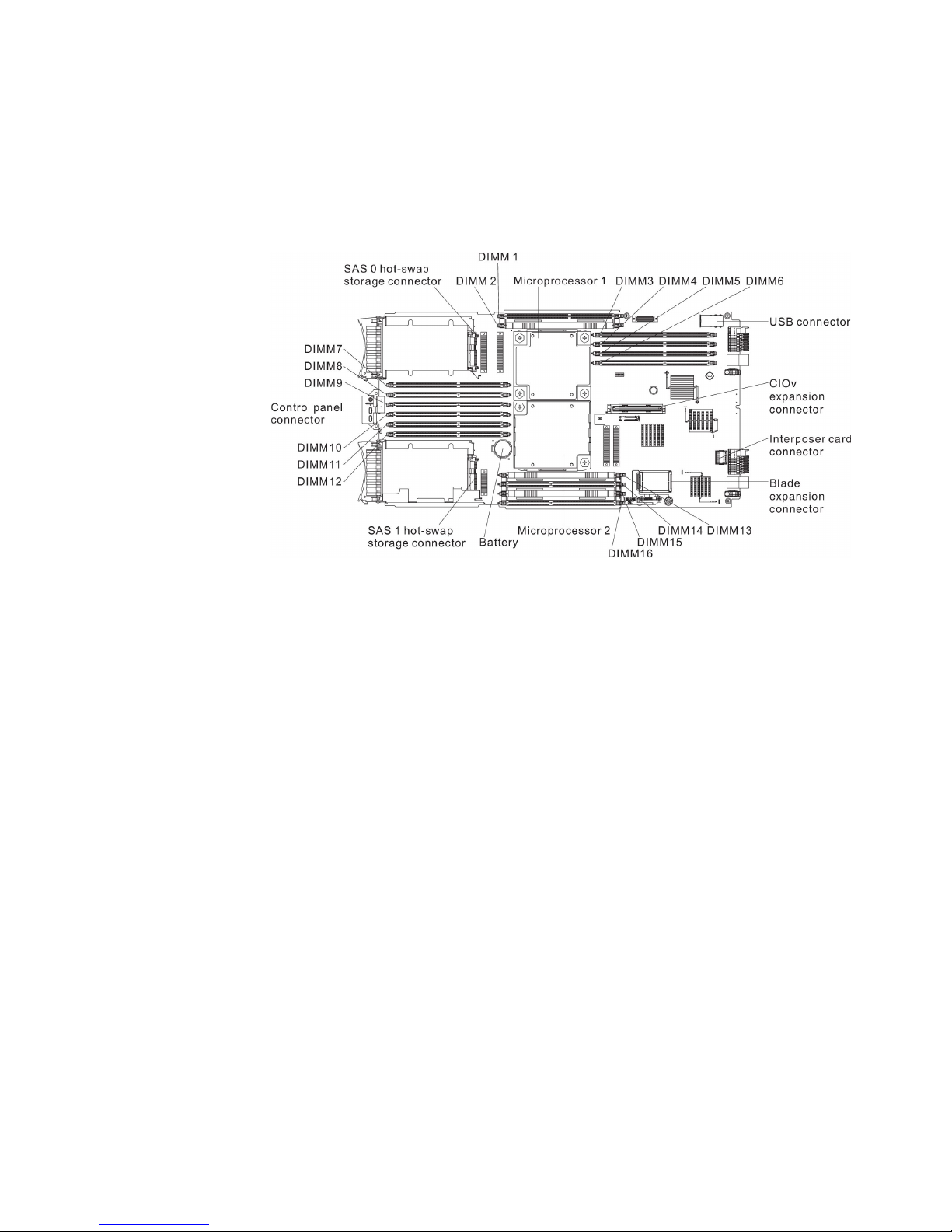
Blade server connectors
Use this information to locate blade server system-board components and
connectors for optional devices.
The following illustration shows the system-board components, including
connectors for user-installable optional devices, in the blade server.
Chapter 2. Power, controls, and indicators 15

16 BladeCenter HS23 Types 7875 and 1929: Installation and User's Guide

Chapter 3. Installing options
Use this information for instructions about installing optional hardware devices in
the blade server. Some option-removal instructions are provided in case you have
to remove one option to install another.
Installation guidelines
Use these guidelines before you install the blade server or optional devices.
Before you install optional devices, read the following information:
v Before you begin, read “Safety” on page v and “Handling static-sensitive
devices” on page 18. This information will help you work safely.
v When you install your new blade server, take the opportunity to download and
apply the most recent firmware updates. This step will help to ensure that any
known issues are addressed and that your blade server is ready to function at
maximum levels of performance.
To download firmware updates for your blade server, go to
http://www.ibm.com/supportportal/ .
v Observe good housekeeping in the area where you are working. Place removed
covers and other parts in a safe place.
v Back up all important data before you make changes to disk drives.
v Before you remove a blade server from the BladeCenter unit, you must shut
down the operating system and turn off the blade server. You do not have to
shut down the BladeCenter unit itself.
v Blue on a component indicates touch points, where you can grip the component
to remove it from or install it in the blade server, open or close a latch, and so
on.
v Orange on a component or an orange label on or near a component indicates
that the component can be hot-swapped, which means that if the server and
operating system support hot-swap capability, you can remove or install the
component while the server is running. (Orange can also indicate touch points
on hot-swap components.) See the instructions for removing or installing a
specific hot-swap component for any additional procedures that you might have
to perform before you remove or install the component.
v For a list of supported optional devices for the blade server, see
http://www.ibm.com/systems/info/x86servers/serverproven/compat/us/.
© Copyright IBM Corp. 2013 17

System reliability guidelines
Use this information to make sure that the blade server meets the proper cooling
and reliability guidelines.
To help make sure that proper cooling and system reliability requirements are met,
review the following guidelines:
v To ensure proper cooling, do not operate the BladeCenter unit without a blade
server, expansion unit, or blade filler installed in each blade-server bay. See the
documentation for your BladeCenter unit for additional information.
v Each microprocessor socket always contains either a microprocessor dust cover
and heat sink filler or a microprocessor and heat sink. If the blade server has
only one microprocessor, it must be installed in microprocessor socket 1.
v DIMMs or DIMM fillers must occupy DIMM connectors 1, 2, 13, 14, 15, and 16
for proper cooling.
v Each hot-swap SAS bay contains a SAS storage drive or filler.
v Make sure that the ventilation holes on the blade server are not blocked.
v The blade server battery must be operational. If the battery becomes defective,
replace it immediately. For instructions, see the Problem Determination and Service
Guide.
Handling static-sensitive devices
Use this information to observe the static-sensitive device requirements.
Attention: Static electricity can damage the blade server and other electronic
devices. To avoid damage, keep static-sensitive devices in their static-protective
packages until you are ready to install them.
To reduce the possibility of damage from electrostatic discharge, observe the
following precautions:
v When you work on a BladeCenter unit that has an electrostatic discharge (ESD)
connector, use a wrist strap, especially when you handle modules, optional
devices, or blade servers. To work correctly, the wrist strap must have a good
contact at both ends (touching your skin at one end and firmly connected to the
ESD connector on the front or back of the BladeCenter unit).
v Limit your movement. Movement can cause static electricity to build up around
you.
v Handle the device carefully, holding it by its edges or its frame.
v Do not touch solder joints, pins, or exposed circuitry.
v Do not leave the device where others can handle and damage it.
v While the device is still in its static-protective package, touch it to an unpainted
metal part of the BladeCenter unit or any unpainted metal surface on any other
grounded rack component in the rack in which you are installing the device for
at least 2 seconds. This drains static electricity from the package and from your
body.
v Remove the device from its package and install it directly into the blade server
without setting down the device. If it is necessary to set down the device, put it
back into its static-protective package. Do not place the device on the blade
server cover or on a metal surface.
v Take additional care when you handle devices during cold weather. Heating
reduces indoor humidity and increases static electricity.
18 BladeCenter HS23 Types 7875 and 1929: Installation and User's Guide
 Loading...