

Page 1

IdeaCentreHorizon227All-In-OnePC
HardwareMaintenanceManual
MachineTypes:F0AQ
Page 2

Page 3

IdeaCentreHorizon227All-In-OnePC
HardwareMaintenanceManual
MachineTypes:F0AQ
Page 4

SecondEdition(May2014)27th
©CopyrightLenovo2014.
LIMITEDANDRESTRICTEDRIGHTSNOTICE:IfdataorsoftwarearedeliveredpursuantaGeneralServices
Administration“GSA”contract,use,reproduction,ordisclosureissubjecttorestrictionssetforthinContractNo.
GS-35F-05925
Page 5

Contents
Chapter1.Aboutthismanual......1
ImportantSafetyInformation..........1
Chapter2.Safetyinformation......3
Generalsafety................3
Electricalsafety...............3
Safetyinspectionguide............5
Handlingelectrostaticdischarge-sensitive
devices..................5
Groundingrequirements............6
Safetynotices................6
Chapter3.Generalinformation.....9
Specifications................9
Chapter4.GeneralCheckout.....11
Chapter5.UsingtheSetupUtility...13
StartingtheLenovoBIOSSetupUtilityprogram.13
Viewingandchangingsettings........13
Usingpasswords..............13
Enablingordisablingadevice........15
Selectingastartupdevice..........16
ExitingtheLenovoBIOSSetupUtilityprogram..17
Chapter6.Symptom-to-FRUIndex..19
Harddiskdrivebooterror..........19
PowerSupplyProblems...........19
POSTerrorcodes.............20
Undeterminedproblems...........20
Chapter7.Replacinghardware....21
Generalinformation.............21
Replacingthekeyboardandmouse......22
Removingtherearcover...........22
Replacingthebattery............24
Replacingamemorymodule.........25
ReplacingtheWi-Ficard...........26
Replacingtheharddiskdrive.........27
Replacingthefanmodule..........29
Replacingtheheat-sinkmodules.......29
Replacingthespeakersystem........30
ReplacingtheI/Oboard...........31
Replacingthepowerswitchboard.......32
Replacingthemotherboard..........33
Replacingthecamera............34
ReplacingtheLEDpanelmodule.......35
Chapter8.FRUlists..........37
Chapter9.Generalinformation....43
AdditionalServiceInformation........43
©CopyrightLenovo2014
iii
Page 6

ivIdeaCentreHorizon227All-In-OnePCHardwareMaintenanceManual
Page 7
Chapter1.Aboutthismanual
ThismanualcontainsserviceandreferenceinformationforIdeaCentreHorizon227All-In-Onecomputers
listedonthecover.ItisintendedonlyfortrainedservicerswhoarefamiliarwithLenovocomputerproducts.
BeforeservicingaLenovoproduct,besuretoreadtheSafetyInformation.
ThedescriptionoftheTV-tunercardinthismanualappliesonlytocomputerswithaTV-tunercardinstalled.
ItdoesnotapplytocomputerswithoutaTV-tunercard.
ImportantSafetyInformation
BesuretoreadallCAUTIONandDANGERsectionsinthismanualbeforefollowinganyoftheinstructions.
VeuillezliretouteslesconsignesdetypeDANGERetA TTENTIONduprésentdocumentavantd’exécuter
lesinstructions.
LesenSieunbedingtalleHinweisevomT yp“ACHTUNG”oder“VORSICHT”indieserDokumentation,bevor
SieirgendwelcheVorgängedurchführen
LeggereleistruzioniintrodottedaA TTENZIONEePERICOLOpresentinelmanualeprimadieseguireuna
qualsiasidelleistruzioni
Certifique-sedelertodasasinstruçõesdecuidadoeperigonestemanualantesdeexecutarqualquer
umadasinstruções
Esimportantequeleatodaslasdeclaracionesdeprecauciónydepeligrodeestemanualantesdeseguir
lasinstrucciones.
©CopyrightLenovo2014
1
Page 8

2IdeaCentreHorizon227All-In-OnePCHardwareMaintenanceManual
Page 9

Chapter2.Safetyinformation
Thischaptercontainsthesafetyinformationthatyouneedtobefamiliarwithbeforeservicingacomputer.
Generalsafety
Followtheserulestoensuregeneralsafety:
•Keeptheareasaroundthecomputerclearandcleanduringandaftermaintenance.
•Whenliftinganyheavyobject:
1.Ensureyoucanstandsafelywithoutslipping.
2.Distributetheweightoftheobjectequallyacrossbothfeet.
3.Liftslowly.Nevermovesuddenlyortwistwhenyouattempttolift.
4.Liftbystandingorbypushingupwithyourlegmuscles;thisactionremovesthestrainfromthe
musclesinyourback.
Donotattempttoliftanyobjectsthatweighmorethan16kg(35lbs.)orobjectsthatyouthink
aretooheavyforyou.
•Donotperformanyactionthatwouldcreateahazardforthecustomer,orwouldmakethecomputer
unsafe.
•Beforeyoustartthecomputer,ensurethatotherservicerepresentativesandcustomerpersonnelarenot
inapositionthatwouldcreateahazardforthem.
•Placeremovedcoversandotherpartsinasafeplace,awayfromallpersonnel,whileyouareservicingthe
computer.
•Keepyourtoolcaseawayfromareasthatpeoplemaywalkthroughtoensureno-onetripsoverit.
•Donotwearlooseclothingthatcanbetrappedinthemovingpartsofamachine.Ensurethatyoursleeves
arefastenedorrolledupaboveyourelbows.Ifyourhairislong,tieorfastenitback.
•Inserttheendsofyournecktieorscarfinsideclothingorfastenitwithanonconductiveclip,approximately
8centimeters(3inches)fromtheend.
•Donotwearjewelry,chains,metal-frameeyeglasses,ormetalfastenersforyourclothing.
Remember:Metalobjectsaregoodelectricalconductors.
•Wearsafetyglasseswhenyouare:hammering,drillingsoldering,cuttingwire,attachingsprings,using
solvents,orworkinginanyotherconditionsthatmightbehazardoustoyoureyes.
•Afterservice,reinstallallsafetyshields,guards,labels,andgroundwires.Replaceanysafetydevice
thatiswornordefective.
•Reattachallcoverscorrectlybeforereturningthecomputertothecustomer.
Electricalsafety
CAUTION:
Electricalcurrentfrompower,telephone,andcommunicationcablescanbehazardous.T oavoid
personalinjuryorequipmentdamage,disconnectanyattachedpowercords,telecommunication
cables,networkcables,andmodemcablesbeforeyouopenthecomputercovers,unlessinstructed
otherwiseintheinstallationandconfigurationprocedures.
©CopyrightLenovo2014
3
Page 10

Observethefollowingruleswhenworkingonelectricalequipment.
Important:Useonlyapprovedtoolsandtestequipment.Somehandtoolshavehandlescoveredwithasoft
materialthatdoesnotinsulateyouwhenworkingwithliveelectricalcurrents.Manycustomershaverubber
floormatsneartheirequipmentthatcontainsmallconductivefiberstodecreaseelectrostaticdischarge.
•Findtheroomemergencypower-off(EPO)switch,disconnectingswitch,orelectricaloutlet.Ifanelectrical
accidentoccurs,youcanthenoperatetheswitchorunplugthepowercordquickly.
•Donotworkaloneunderhazardousconditionsornearequipmentthathashazardousvoltages.
•Disconnectallpowerbefore:
–Performingamechanicalinspection
–Workingnearpowersupplies
–RemovingorinstallingFieldReplaceableUnits(FRUs)
•Beforeyoustarttoworkonthecomputer,unplugthepowercord.Ifyoucannotunplugit,askthe
customertopower-offtheelectricaloutletthatsuppliespowertothemachineandtolocktheelectrical
outletintheoffposition.
•Ifyouneedtoworkonacomputerthathasexposedelectricalcircuits,observethefollowingprecautions:
–Ensurethatanotherperson,familiarwiththepower-offcontrols,isnearyou.
Remember:Anotherpersonmustbetheretoswitchoffthepower,ifnecessary.
–Useonlyonehandwhenworkingwithpowered-onelectricalequipment;keeptheotherhandinyour
pocketorbehindyourback.
Remember:Theremustbeacompletecircuittocauseelectricalshock.Byobservingtheaboverule,
youmaypreventacurrentfrompassingthroughyourbody.
–Whenusingatester,setthecontrolscorrectlyandusetheapprovedprobeleadsandaccessoriesfor
thattester.
–Standonsuitablerubbermats(obtainedlocally,ifnecessary)toinsulateyoufromgroundssuchas
metalfloorstripsandmachineframes.
Observethespecialsafetyprecautionswhenyouworkwithveryhighvoltages;theseinstructionsarein
thesafetysectionsofthemaintenanceinformation.Useextremecarewhenmeasuringhighvoltages.
•Regularlyinspectandmaintainyourelectricalhandtoolstoensuretheyaresafetouse.
•Donotusewornorbrokentoolsandtesters.
•Neverassumethatpowerhasbeendisconnectedfromacircuit.First,checkthatithasbeenpoweredoff.
•Alwayslookcarefullyforpossiblehazardsinyourworkarea.Examplesofthesehazardsarewetfloors,
non-groundedpowerextensioncables,conditionsthatmaycauseorallowpowersurges,andmissing
safetygrounds.
•Donottouchliveelectricalcircuitswiththereflectivesurfaceofaplasticdentalmirror.Thissurfaceis
conductive,andtouchingalivecircuitcancausepersonalinjuryanddamagetothecomputer.
•Donotservicethefollowingpartswiththepoweronwhentheyareremovedfromtheirnormaloperating
positionsinacomputer:
–Powersupplyunits
–Pumps
–Blowersandfans
–Motorgenerators
andsimilarunits.(Thispracticeensurescorrectgroundingoftheunits.)
•Ifanelectricalaccidentoccurs:
–Usecaution;donotbecomeavictimyourself.
4IdeaCentreHorizon227All-In-OnePCHardwareMaintenanceManual
Page 11

–Switchoffpower.
–Sendanotherpersontogetmedicalaid.
Safetyinspectionguide
Theintentofthisinspectionguideistoassistyouinidentifyingpotentialhazardsposedbytheseproducts.
Eachcomputer,asitwasdesignedandbuilt,hadrequiredsafetyitemsinstalledtoprotectusersand
servicepersonnelfrominjury.Thisguideaddressesonlythoseitems.However,goodjudgmentshouldbe
usedtoidentifypotentialsafetyhazardsduetoattachmentoffeaturesoroptionsnotcoveredbythis
inspectionguide.
Ifanyhazardsarepresent,youmustdeterminehowserioustheapparenthazardcouldbeandwhetheryou
cancontinuewithoutfirstresolvingtheproblem.
Considerthefollowingitemsandthesafetyhazardstheypresent:
•Electricalhazards,especiallyprimarypower(primaryvoltageontheframecancauseseriousorfatal
electricalshock).
•Explosivehazards,suchasadamagedCRTfaceorbulgingcapacitor
•Mechanicalhazards,suchaslooseormissinghardware
Theguideconsistsofaseriesofstepspresentedasachecklist.Beginthecheckswiththepoweroff,and
thepowercorddisconnected.
Checklist:
1.Checkexteriorcoversfordamage(loose,broken,orsharpedges).
2.Power-offthecomputer.Disconnectthepowercord.
3.Checkthepowercordfor:
a.Athird-wiregroundconnectoringoodcondition.Useametertomeasurethird-wireground
continuityfor0.1ohmorlessbetweentheexternalgroundpinandframeground.
b.Thepowercordshouldbetheappropriatetypeasspecifiedinthepartslistings.
c.Insulationmustnotbefrayedorworn.
4.Removethecover.
5.Checkforanyobviousalterations.Usegoodjudgmentastothesafetyofanyalterations.
6.Checkinsidetheunitforanyobvioushazards,suchasmetalfilings,contamination,waterorother
liquids,orsignsoffireorsmokedamage.
7.Checkforworn,frayed,orpinchedcables.
8.Checkthatthepower-supplycoverfasteners(screwsorrivets)havenotbeenremovedortamperedwith.
Handlingelectrostaticdischarge-sensitivedevices
Anycomputerpartcontainingtransistorsorintegratedcircuits(ICs)shouldbeconsideredsensitiveto
electrostaticdischarge(ESD).ESDdamagecanoccurwhenthereisadifferenceinchargebetweenobjects.
ProtectagainstESDdamagebyequalizingthechargesothatthecomputer,thepart,theworkmat,andthe
personhandlingthepartareallatthesamecharge.
Notes:
1.Useproduct-specificESDprocedureswhentheyexceedtherequirementsnotedhere.
2.MakesurethattheESDprotectivedevicesyouusehavebeencertified(ISO9000)asfullyeffective.
WhenhandlingESD-sensitiveparts:
Chapter2.Safetyinformation5
Page 12

•Keepthepartsinprotectivepackagesuntiltheyareinsertedintotheproduct.
•Avoidcontactwithotherpeoplewhilehandlingthepart.
•Wearagroundedwriststrapagainstyourskintoeliminatestaticonyourbody.
•Preventthepartfromtouchingyourclothing.Mostclothingisinsulativeandretainsachargeeven
whenyouarewearingawriststrap.
•Usetheblacksideofagroundedworkmattoprovideastatic-freeworksurface.Thematisespecially
usefulwhenhandlingESD-sensitivedevices.
•Selectagroundingsystem,suchasthoselistedbelow,toprovideprotectionthatmeetsthespecific
servicerequirement.
Note:TheuseofagroundingsystemisdesirablebutnotrequiredtoprotectagainstESDdamage.
–AttachtheESDgroundcliptoanyframeground,groundbraid,orgreen-wireground.
–UseanESDcommongroundorreferencepointwhenworkingonadouble-insulatedor
battery-operatedsystem.Y oucanusecoaxorconnector-outsideshellsonthesesystems.
–Usetheroundground-prongoftheACplugonAC-operatedcomputers.
Groundingrequirements
Electricalgroundingofthecomputerisrequiredforoperatorsafetyandcorrectsystemfunction.Proper
groundingoftheelectricaloutletcanbeverifiedbyacertifiedelectrician.
Safetynotices
TheCAUTIONandDANGERsafetynoticesinthissectionareprovidedinthelanguageofEnglish.
DANGER
Electricalcurrentfrompower,telephoneandcommunicationcablesishazardous.
Toavoidashockhazard:
•Donotconnectordisconnectanycablesorperforminstallation,maintenance,orreconfiguration
ofthisproductduringanelectricalstorm.
•Connectallpowercordstoaproperlywiredandgroundedelectricaloutlet.
•Connectanyequipmentthatwillbeattachedtothisproducttoaproperlywiredoutlet.
•Whenpossible,useonehandonlytoconnectordisconnectsignalcables.
•Neverturnonanyequipmentwhenthereisevidenceoffire,water,orstructuraldamage.
•Disconnecttheattachedpowercords,telecommunicationscables,networkcables,andmodem
cablesbeforeyouopenthedevicecovers,unlessinstructedotherwiseintheinstallationand
configurationprocedures.
•Connectanddisconnectcablesasdescribedinthefollowingtablewheninstalling,moving,or
openingcoversonthisproductorattacheddevices.
6IdeaCentreHorizon227All-In-OnePCHardwareMaintenanceManual
Page 13
ToConnect
1.T urneverythingOFF .
2.First,attachallcablestodevices.
3.Attachsignalcablestoconnectors.
4.Attachpowercordstooutlet.
5.T urndeviceON.
ToDisconnect
1.T urneverythingOFF .
2.First,removepowercordsfromoutlets.
3.Removesignalcablesfromconnectors.
4.Removeallcablesfromdevices.
CAUTION:
Whenreplacingthelithiumbattery,useonlyPartNumber45C1566oranequivalenttypebattery
recommendedbythemanufacturer.Ifyoursystemhasamodulecontainingalithiumbattery,replace
itonlywiththesamemoduletypemadebythesamemanufacturer.Thebatterycontainslithiumand
canexplodeifnotproperlyused,handled,ordisposedof.
Donot:
•Throwintoorimmerseinwater
•Heattomorethan100°C(212°F)
•Repairordisassemble
Disposeofthebatteryasrequiredbylocalordinancesorregulations.
CAUTION:
Whenlaserproducts(suchasCD-ROMs,DVD-ROMdrives,fiberopticdevices,ortransmitters)are
installed,notethefollowing:
•Donotremovethecovers.Removingthecoversofthelaserproductcouldresultinexposureto
hazardouslaserradiation.Therearenoserviceablepartsinsidethedevice.
•Useofcontrolsoradjustmentsorperformanceofproceduresotherthanthosespecifiedherein
mightresultinhazardousradiationexposure.
DANGER
SomelaserproductscontainanembeddedClass3AorClass3Blaserdiode.Notethefollowing:
Thesediodesemitradiationwhenopen.Donotstareintothebeam,donotviewdirectlywith
opticalinstruments,andavoiddirectexposuretothebeam.
Chapter2.Safetyinformation7
Page 14
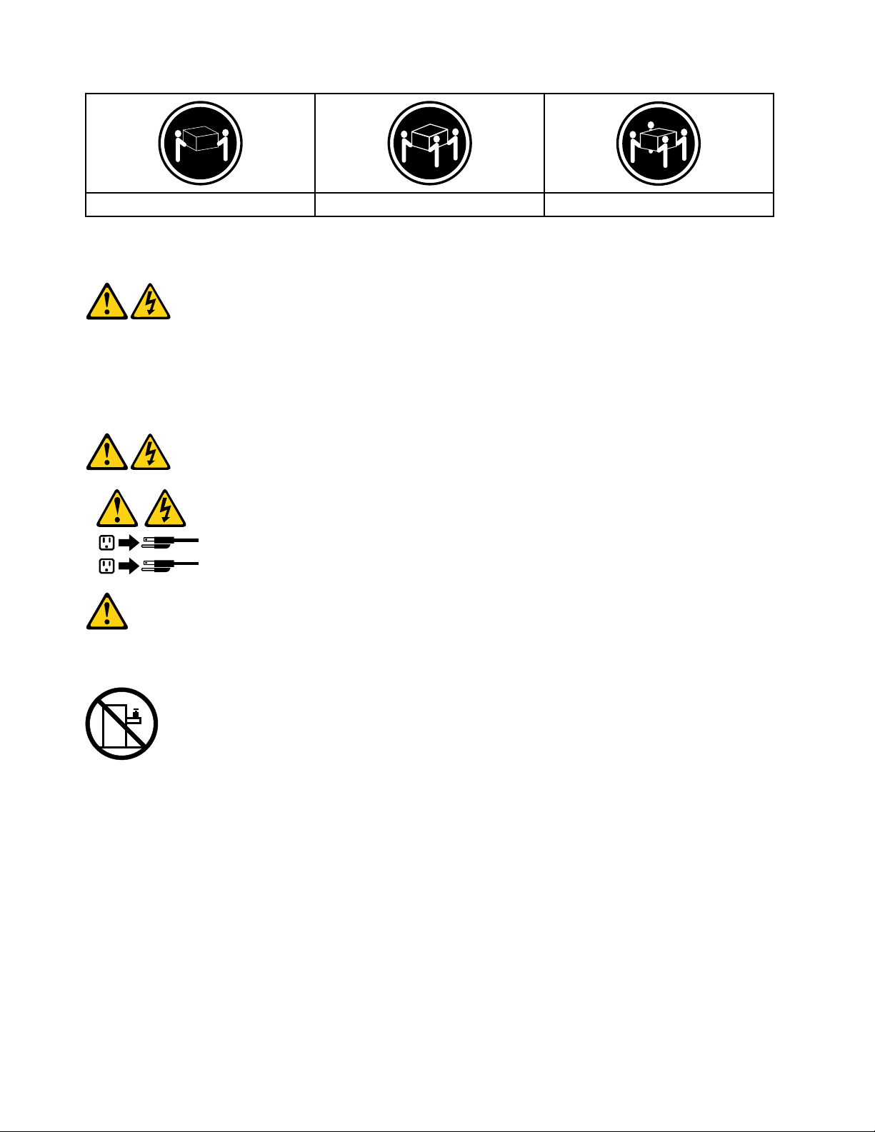
≥18kg(37lbs)≥32kg(70.5lbs)≥55kg(121.2lbs)
1
2
CAUTION:
Usesafepracticeswhenlifting.
CAUTION:
Thepowercontrolbuttononthedeviceandthepowerswitchonthepowersupplydonotturnoff
theelectricalcurrentsuppliedtothedevice.Thedevicealsomighthavemorethanonepower
cord.T oremoveallelectricalcurrentfromthedevice,ensurethatallpowercordsaredisconnected
fromthepowersource.
CAUTION:
Donotplaceanyobjectweighingmorethan82kg(180lbs.)ontopofrack-mounteddevices.
8IdeaCentreHorizon227All-In-OnePCHardwareMaintenanceManual
Page 15

Chapter3.Generalinformation
Thischapterprovidesgeneralinformationthatappliestoallcomputermodelscoveredbythismanual.
Specifications
Thissectionliststhephysicalspecificationsforyourcomputer.
Thissectionliststhephysicalspecificationsforyourcomputer .
TypeIdeaCentreHorizon227
Thissectionliststhephysicalspecifications.
Environment
Airtemperature:
Operating:10°to35°C
Transit:-20°to55°C
Humidity:
Operating:35%to80%
Transit:20%to90%(40°C)
Altitude:86KPato106KPa
Electricalinput:
Inputvoltage:90V-264V(AC)
Inputfrequency:47Hz-63Hz
©CopyrightLenovo2014
9
Page 16

10IdeaCentreHorizon227All-In-OnePCHardwareMaintenanceManual
Page 17

Chapter4.GeneralCheckout
Attention:Thedrivesinthecomputeryouareservicingmighthavebeenrearrangedorthedrivestartup
sequencemayhavebeenchanged.Beextremelycarefulduringwriteoperationssuchascopying,saving,or
formatting.Dataorprogramscanbeoverwrittenifyouselectanincorrectdrive.
Generalerrormessagesappearifaproblemorconflictisfoundbyanapplication,theoperatingsystem,or
both.Foranexplanationofthesemessages,refertotheinformationsuppliedwiththatsoftwarepackage.
Usethefollowingproceduretohelpdeterminethecauseoftheproblem:
1.Power-offthecomputerandallexternaldevices.
2.Checkallcablesandpowercords.
3.Setalldisplaycontrolstothemiddleposition.
4.Power-onallexternaldevices.
5.Power-onthecomputer.
•Lookfordisplayederrorcodes.
•Lookforreadableinstructionsoramainmenuonthedisplay.
Ifyoudidnotreceivethecorrectresponse,proceedtostep6.
Ifyoudidreceivethecorrectresponse,proceedtostep7.
6.Ifoneofthefollowinghappens,followtheinstructiongiven:
•IfthecomputerdisplaysaPOSTerror,goto“POSTerrorcodes” .
•Ifthecomputerhangsandnoerrorisdisplayed,continueatstep7.
7.Iftheteststopsandyoucannotcontinue,replacethelastdevicetested.
©CopyrightLenovo2014
11
Page 18

12IdeaCentreHorizon227All-In-OnePCHardwareMaintenanceManual
Page 19

Chapter5.UsingtheSetupUtility
TheSetupUtilityprogramisusedtoviewandchangetheconfigurationsettingsofyourcomputer,regardless
ofwhichoperatingsystemyouareusing.However,theoperatingsystemsettingsmightoverrideanysimilar
settingsintheSetupUtilityprogram.
StartingtheLenovoBIOSSetupUtilityprogram
TostarttheLenovoBIOSSetupUtilityprogram,dothefollowing:
1.Ifyourcomputerisalreadyonwhenyoustartthisprocedure,shutdowntheoperatingsystemand
turnoffthecomputer.
2.PressandholdtheF1keythenturnonthecomputer.WhentheLenovoBIOSSetupUtilityprogramis
displayed,releasetheF1key.
Note:IfaPower-OnPasswordoranAdministratorPasswordhasbeenset,theSetupUtilityprogrammenu
willnotbedisplayeduntilyoutypeyourpassword.Formoreinformation,see“Usingpasswords. ”
Viewingandchangingsettings
SystemconfigurationoptionsarelistedintheLenovoBIOSSetupUtilityprogrammenu.T ovieworchange
settings,see“StartingtheSetupUtilityprogram.”
YoumustusethekeyboardwhenusingtheLenovoBIOSSetupUtilitymenu.Thekeysusedtoperform
varioustasksaredisplayedonthebottomofeachscreen.
Usingpasswords
YoucanusetheLenovoBIOSSetupUtilityprogramtosetpasswordstopreventunauthorizedpersons
fromgainingaccesstoyourcomputeranddata.See“StartingtheSetupUtilityprogram.”Thefollowing
typesofpasswordsareavailable:
•AdministratorPassword
•Power-OnPassword
Youdonothavetosetanypasswordstouseyourcomputer.However,ifyoudecidetosetpasswords,read
thefollowingsections.
Passwordconsiderations
Apasswordcanbeanycombinationoflettersandnumbersupto16characters(a-zand0-9).Forsecurity
reasons,itisagoodideatouseastrongpasswordthatcannotbeeasilycompromised.Wesuggestthat
passwordsshouldfollowtheserules:
•Forastrongpassword,use7-16charactersandamixoflettersandnumbers.
•Donotuseyournameoryourusername.
•Donotuseacommonwordoracommonname.
•Usesomethingsignificantlydifferentfromyourpreviouspassword.
Attention:AdministratorandPower-Onpasswordsarenotcasesensitive.
©CopyrightLenovo2014
13
Page 20

AdministratorPassword
SettinganAdministratorPassworddetersunauthorizedpersonsfromchangingconfigurationsettings.Y ou
mightwanttosetanAdministratorPasswordifyouareresponsibleformaintainingthesettingsofseveral
computers.
AfteryousetanAdministratorPassword,apasswordpromptisdisplayedeverytimeyouaccesstheLenovo
BIOSSetupUtilityprogram.
IfboththeAdministratorandPower-OnPasswordareset,youcantypeeitherpassword.However,youmust
useyourAdministratorPasswordtochangeanyconfigurationsettings.
Setting,changing,ordeletinganAdministratorPassword
TosetanAdministratorPassword,dothefollowing:
Note:Apasswordcanbeanycombinationoflettersandnumbersupto16characters(a-zand0-9).For
moreinformation,see“Passwordconsiderations”onpage13.
1.StarttheLenovoBIOSSetupUtilityprogram(see“StartingtheLenovoBIOSSetupUtilityprogram”on
page13).
2.FromtheSecuritymenu,selectSetAdministratorPasswordandpresstheEnterkey.
3.Thepassworddialogboxwillbedisplayed.T ypethepasswordthenpresstheEnterkey.
4.Retypethepasswordtoconfirm,thenpresstheEnterkey.Ifyoutypedthepasswordcorrectly,the
passwordwillbeinstalled.ASetupNoticewillbedisplayedconfirmingthatyourchangeshasbeen
saved.
5.ReturntotheLenovoBIOSSetupUtilityprogrammenuandselecttheExitoption.
6.SelectSaveChangesandExitfromthemenu.
TochangeanAdministratorPassword,dothefollowing:
1.StarttheLenovoBIOSSetupUtilityprogram(see“StartingtheLenovoBIOSSetupUtilityprogram”on
page13).
2.FromtheSecuritymenu,selectSetAdministratorPasswordandpresstheEnterkey.
3.Thepassworddialogboxwillbedisplayed.TypethecurrentpasswordthenpresstheEnterkey.
4.Typethenewpassword,thenpresstheEnterkey.Retypethenewpasswordtoconfirmit.Ifyoutyped
thenewpasswordcorrectly,thenewpasswordwillbeinstalled.ASetupNoticewillbedisplayed
confirmingthatyourchangeshavebeensaved.
5.ReturntotheLenovoBIOSSetupUtilityprogrammenuandselecttheExitoption.
6.SelectSaveChangesandExitfromthemenu.
TodeleteapreviouslysetAdministratorPassword,dothefollowing:
1.StarttheLenovoBIOSSetupUtilityprogram(see“StartingtheLenovoBIOSSetupUtilityprogram”on
page13).
2.FromtheSecuritymenu,selectSetAdministratorPasswordandpresstheEnterkey.
3.Thepassworddialogboxwillbedisplayed.T ypethecurrentpasswordandpresstheEnterkey.
4.Leaveeachnewpasswordlineitemblank,thenpresstheEnterkey.ASetupNoticewillbedisplayed
confirmingthatyourchangeshavebeensaved.
5.ReturntotheLenovoBIOSSetupUtilityprogrammenuandselecttheExitoption.
6.SelectSaveChangesandExitfromthemenu.
14IdeaCentreHorizon227All-In-OnePCHardwareMaintenanceManual
Page 21

Power-OnPassword
WhenaPower-OnPasswordisset,youcannotstarttheLenovoBIOSSetupUtilityprogramuntilavalid
passwordistypedfromthekeyboard.
Setting,changing,ordeletingaPower-OnPassword
Note:Apasswordcanbeanycombinationoflettersandnumbersupto16characters(a-zand0-9).
TosetaPower-OnPassword,dothefollowing:
1.StarttheLenovoBIOSSetupUtilityprogram(see”StartingtheLenovoBIOSSetupUtilityprogram”on
page13).
2.FromtheSecuritymenu,selectSetPower-OnPasswordandpresstheEnterkey.
3.Thepassworddialogboxwillbedisplayed.T ypethepassword,thenpresstheEnterkey.
4.Retypethepasswordtoconfirm.Ifyoutypedthepasswordcorrectly,thepasswordwillbeinstalled.
5.ReturntotheLenovoBIOSSetupUtilityprogrammenuandselecttheExitoption.
6.SelectSaveChangesandExitfromthemenu.
TochangeaPower-OnPassword,dothefollowing:
1.StarttheLenovoBIOSSetupUtilityprogram(see”StartingtheLenovoBIOSSetupUtilityprogram”on
page13).
2.FromtheSecuritymenu,selectSetPower-OnPasswordandpresstheEnterkey.
3.Thepassworddialogboxwillbedisplayed.TypethecurrentpasswordthenpresstheEnterkey.
4.Typethenewpassword,thenpresstheEnterkey.Retypethenewpasswordtoconfirmit.Ifyoutyped
thenewpasswordcorrectly,thenewpasswordwillbeinstalled.ASetupNoticewillbedisplayed
confirmingthatyourchangeshavebeensaved.
5.ReturntotheLenovoBIOSSetupUtilityprogrammenuandselecttheExitoption.
6.SelectSaveChangesandExitfromthemenu.
TodeleteapreviouslysetPower-OnPassword,dothefollowing:
1.StarttheLenovoBIOSSetupUtilityprogram(see”StartingtheLenovoBIOSSetupUtilityprogram”on
page13).
2.FromtheSecuritymenu,selectSetPower-OnPasswordandpresstheEnterkey.
3.Thepassworddialogboxwillbedisplayed.T ypethecurrentpasswordandpresstheEnterkey.
4.Leaveeachnewpasswordlineitemblank,thenpressEnter.ASetupNoticewillbedisplayedconfirming
thatyourchangeshavebeensaved.
5.ReturntotheLenovoBIOSSetupUtilityprogrammenuandselecttheExitoption.
6.SelectSaveChangesandExitfromthemenu.
Enablingordisablingadevice
TheDevicesoptionsisusedtoenableordisableuseraccesstothefollowing:
USBFunctionsSelectwhethertoenableordisableUSB(UniversalSerial
Bus)functions.Ifthefunctionsaredisabled,noUSB
devicescanbeused.
Chapter5.UsingtheSetupUtility15
Page 22

SATAModeSelectDisabled/IDE/AHCImode.Devicedriversupport
isrequiredforAHCIorRAID.Dependingonhowthehard
diskdriveimagewasinstalled,changingthissettingmay
preventthesystemfrombooting.
OnboardAudioControllerSelectwhethertoenableordisabletheOnboard
AudioController.WhenthisfeatureissettoDisabled
alldevicesconnectedtotheaudioconnectors(e.g.
headphonesoramicrophone)aredisabledandcannot
beused.
Toenableordisableadevice,dothefollowing:
1.StarttheSetupUtilityprogram(see“StartingtheSetupUtilityprogram”onpage13).
2.FromtheSetupUtilityprogrammenu,selectDevices.
3.Selectanoptionasfollows:
SelectUSBSetup,presstheEnterkey,thenselectUSBFunctions.
SelectATADriversSetup,presstheEnterkey,thenselectSA T AMode.
SelectAudioSetup,presstheEnterkey,thenselectOnboardAudioController.
4.SelectDisabledorEnabledandpresstheEnterkey.
5.ReturntotheLenovoBIOSSetupUtilityprogrammenuandselecttheExitoption.
6.SelectSaveChangesandExitfromthemenu.
Notes:
a.Ifyoudonotwanttosavethesettings,selectDiscardChangesandExitfromthemenu.
Selectingastartupdevice
IfyourcomputerdoesnotbootfromadevicesuchastheCD/DVD-ROMdrivediskorharddiskasexpected,
followoneoftheproceduresbelow.
Selectingatemporarystartupdevice
Usethisproceduretostartupfromanybootdevice.
Note:NotallCDs,DVDsorharddiskdrivesarebootable.
1.Turnoffyourcomputer.
2.PressandholdtheF12keythenturnonthecomputer.WhentheStartupDeviceMenuappears,
releasetheF12key.
Note:IftheStartupDeviceMenudoesnotdisplayusingthesesteps,repeatedlypressandreleasethe
F12keyratherthankeepingitpressedwhenturningonthecomputer.
3.Use↑and↓arrowstoselectthedesiredstartupdevicefromtheStartupDeviceMenuandpress
theEnterkeytobegin.
Note:SelectingastartupdevicefromtheStartupDeviceMenudoesnotpermanentlychangethe
startupsequence.
Selectingorchangingthestartupdevicesequence
Tovieworpermanentlychangetheconfiguredstartupdevicesequence,dothefollowing:
16IdeaCentreHorizon227All-In-OnePCHardwareMaintenanceManual
Page 23

1.StarttheLenovoBIOSSetupUtilityprogram(see“StartingtheLenovoBIOSSetupUtilityprogram”on
page13).
2.FromtheLenovoBIOSSetupUtilityprogrammainmenu,selecttheStartupoption.
3.PresstheEnterkey,andselectthedevicesforthePrimaryBootSequence.Readtheinformation
displayedontherightsideofthescreen.
4.Use↑and↓arrowstoselectadevice.Usethe<+>or<->keystomoveadeviceupordown.Usethe
<×>keytoexcludethedevicefromorincludethedeviceinthebootsequence.
5.ReturntotheLenovoBIOSSetupUtilityprogrammenuandselecttheExitoption.
6.SelectSaveChangesandExitfromthemenu.
Notes:
a.Ifyoudonotwanttosavethesettings,selectDiscardChangesandExitfromthemenu.
b.Ifyouhavechangedthesesettingsandwanttoreturntothedefaultsettings,selectLoadOptimal
Defaultsfromthemenu.
ExitingtheLenovoBIOSSetupUtilityprogram
Afteryoufinishviewingorchangingsettings,presstheEsckeytoreturntotheLenovoBIOSSetupUtility
programmainmenu.Y oumighthavetopresstheEsckeyseveraltimes.Dooneofthefollowing:
•Ifyouwanttosavethenewsettings,selectSaveChangesandExitfromthemenu.WhentheSave
&resetwindowshows,selecttheYesbutton,andthenpresstheEnterkeytoexittheLenovoBIOS
SetupUtilityprogram.
•Ifyoudonotwanttosavethesettings,selectDiscardChangesandExitfromthemenu.Whenthe
ResetWithoutSavingwindowshows,selecttheY esbutton,andthenpresstheEnterkeytoexitthe
LenovoBIOSSetupUtilityprogram.
Chapter5.UsingtheSetupUtility17
Page 24

18IdeaCentreHorizon227All-In-OnePCHardwareMaintenanceManual
Page 25

Chapter6.Symptom-to-FRUIndex
TheSymptom-to-FRUindexlistserrorsymptomsandpossiblecauses.Themostlikelycauseislistedfirst.
AlwaysbeginwithChapter4,“GeneralCheckout, ”onpage11.Thisindexcanalsobeusedtohelpyou
decidewhichFRUstohaveavailablewhenservicingacomputer.Ifyouareunabletocorrecttheproblem
usingthisindex,goto“Undeterminedproblems”onpage20.
Notes:
•Ifyouhavebothanerrormessageandanincorrectaudioresponse,diagnosetheerrormessagefirst.
•Ifyoucannotrunthediagnostictestsoryougetadiagnosticerrorcodewhenrunningatestbutdid
receiveaPOSTerrormessage,diagnosethePOSTerrormessagefirst.
•Ifyoudidnotreceiveanyerrormessagelookforadescriptionofyourerrorsymptomsinthefirstpartof
thisindex.
Harddiskdrivebooterror
Aharddiskdrivebooterrorcanhavethefollowingcauses.
Error
Thestartupdriveisnotincludedinthebootsequence
configuration.
Nooperatingsystemisinstalledonthebootdrive.Installanoperatingsystemonthebootdrive.
Thebootsectoronthestartupdriveiscorrupted.
Thedriveisdefective.
FRU/Action
Checktheconfigurationandensurethestartupdriveis
inthebootsequence.
Thedrivemustbeformatted.Dothefollowing:
1.Attempttobackupthedataonthefailingharddisk
drive.
2.Usetheoperatingsystemtoformattheharddisk
drive.
Replacetheharddiskdrive.
PowerSupplyProblems
Followtheseproceduresifyoususpectthereisapowersupplyproblem.
Check/VerifyFRU/Action
Checkthatthefollowingareproperlyinstalled:
•PowerCord
•On/OffSwitchconnector
•SystemBoardPowerSupplyconnectors
•Microprocessorconnections
Checkthepowercord.PowerCord
Checkthepower-onswitch.Power-onSwitch
Reseatconnectors
©CopyrightLenovo2014
19
Page 26

POSTerrorcodes
Eachtimeyouturnthecomputeron,itperformsaseriesofteststocheckthatthesystemisoperating
correctlyandthatcertainoptionsareset.ThisseriesoftestsiscalledthePower-OnSelf- T est,orPOST.
POSTdoesthefollowing:
•Checkssomebasicmotherboardoperations
•Checksthatthememoryisworkingcorrectly
•Startsvideooperations
•Verifiesthatthebootdriveisworking
POSTErrorMessageDescription/Action
Keyboarderror
RebootandSelectproperBootdeviceorInsertBoot
MediainselectedBootdevice
Cannotinitializethekeyboard.Makesurethekeyboard
isproperlyconnectedtothecomputerandthatnokeys
areheldpressedduringPOST.Topurposelyconfigure
thecomputerwithoutakeyboard,selectKeyboardless
operationinStartupandsettheoptiontoEnabled.The
BIOSthenignoresthemissingkeyboardduringPOST.
TheBIOSwasunabletofindasuitablebootdevice.Make
surethebootdriveisproperlyconnectedtothecomputer.
Makesureyouhavebootablemediainthebootdevice.
Undeterminedproblems
1.Power-offthecomputer.
2.Removeordisconnectthefollowingcomponents(ifconnectedorinstalled)oneatatime.
a.Externaldevices(modem,printer,ormouse)
b.Extendedvideomemory
c.ExternalCache
d.ExternalCacheRAM
e.Harddiskdrive
f.Diskdrive
3.Power-onthecomputertore-testthesystem.
4.Repeatsteps1through3untilyoufindthefailingdeviceorcomponent.
Ifalldevicesandcomponentshavebeenremovedandtheproblemcontinues,replacethesystemboard.
20IdeaCentreHorizon227All-In-OnePCHardwareMaintenanceManual
Page 27

Chapter7.Replacinghardware
Attention:Donotremovethecomputercoverorattemptanyrepairbeforereadingthe“Importantsafetyinformation”
intheSafetyandWarrantyGuidethatwasincludedwithyourcomputer.ToobtaincopiesoftheSafetyandWarranty
Guide,gototheSupportWebsiteat:http://support.lenovo.com.
Note:UseonlypartsprovidedbyLenovo.
Generalinformation
Pre-disassemblyinstructions
Beforestartingthedisassemblyprocedure,makesurethatyoudothefollowing:
1.Turnoffthepowertothesystemandallperipherals.
2.Unplugallpowerandsignalcablesfromthecomputer.
3.Placethesystemonaflat,stablesurface.
©CopyrightLenovo2014
21
Page 28

Replacingthekeyboardandmouse
Toreplacethekeyboardandmouse:
Step1.Removeanymedia(disks,CDs,DVDsormemorycards)fromthedrives,shutdowntheoperating
system,andturnoffthecomputerandallattacheddevices.
Step2.Unplugallpowercordsfromelectricaloutlets.
Step3.Disconnectallcablesattachedtothecomputer.Thisincludespowercords,input/output(I/O)
cables,andanyothercablesthatareconnectedtothecomputer.Referto“Leftandrightview”
and“Rearview”forhelpwithlocatingthevariousconnectors.
Note:YourkeyboardwillbeconnectedtoaUSBconnectorononesideorattherearofthe
computer.
Step4.Disconnectthedefectivekeyboardcablefromthecomputerandconnectthenewkeyboardcable
tothesameconnector.
Note:Themousecanbereplacedusingthesamemethod.
Removingtherearcover
Note:T urnoffthecomputerandwait3to5minutestoletitcooldownbeforeremovingthebasecover.
Note:Itmaybehelpfultoplacethecomputerface-downonasoftflatsurfaceforthisprocedure.Lenovo
recommendsthatyouuseablanket,towel,orothersoftclothtoprotectthecomputerscreenfromscratches
orotherdamage.
Toremovethebasecover:
Step1.Removeanymedia(disks,CDs,DVDs,ormemorycards)fromthedrives,shutdowntheoperating
system,andturnoffthecomputerandallattacheddevices.
Step2.Unplugallpowercordsfromelectricaloutlets.
Step3.Disconnectallcablesattachedtothecomputer.Thisincludespowercords,input/output(I/O)
cables,andanyothercablesthatareconnectedtothecomputer.Referto“Leftandrightview”
and“Rearview”forhelpwithlocatingthevariousconnectors.
22IdeaCentreHorizon227All-In-OnePCHardwareMaintenanceManual
Page 29

Step4.Forthisprocedureitrequiresusingaflatheadscrewdriver.Useapieceofsoftclothestowrapthe
screwdriverheadbeforeproceeding.
Step5.Thefrontpanelandtherearcoverarepinedtogether,usethewrappedscrewdrivertopushintothe
holeasillustratedtoforcethefrontpanelseparatingfromtherearcover.Forthisprocedureitmight
requiresusingsomestrengthenswhilepushing.
1Workingalongthegapopenedin-betweenthe
frontpanelandtherearcovergentlytoseparatingthefrontpanelfromrearcover.2
Chapter7.Replacinghardware23
Page 30

Step6.Disconnectthetwoscalarcablesfromtheconnectorsonthemotherboardasshown.12
Step7.Putthefrontpanelandrearcoveraside.
Step8.T oreattachtherearcover:
a.Lineupthefrontpanelwiththerearcover,andthenreconnectthetwoscalarcablestothe
motherboard.
b.Pressdownalongtheedgeoftherearcoverandsecuretherearcovertothefrontpanelwith
themountingpins.
Replacingthebattery
Note:T urnoffthecomputerandwait3to5minutestoletitcooldownbeforeremovingthebasecover.
Toreplacethebattery:
Step1.Removeanymedia(disks,CDs,DVDs,ormemorycards)fromthedrives,shutdowntheoperating
system,andturnoffthecomputerandallattacheddevices.
Step2.Unplugallpowercordsfromelectricaloutlets.
Step3.Disconnectallcablesattachedtothecomputer.Thisincludespowercords,input/output(I/O)
cables,andanyothercablesthatareconnectedtothecomputer.Referto“Leftandrightview”
and“Rearview”forhelpwithlocatingthevariousconnectors.
Step4.Removetherearcover.Referto“Removingtherearcover” .
24IdeaCentreHorizon227All-In-OnePCHardwareMaintenanceManual
Page 31

Step5.Disconnectthepowercablefromtheconnectoronthemotherboard.1
Step6.Removethesixscrewsthatsecurethebatterytotherearcover2,thenliftupthebatterypack
asshown.
Step7.T oinstallanewbattery:
a.Lineuptheholeswithmountingholesontherearcover,thenplaceitintoposition.
b.Securethenewbatterytothechassiswiththesixscrews.
c.Connectthepowercabletotheconnectoronthemotherboard.
Step8.Reattachtherearcover.
Replacingamemorymodule
Attention:Turnoffthecomputerandwait3to5minutestoletitcooldownbeforeremovingthebasecover.
Toreplaceamemorymodule:
Step1.Removeanymedia(disks,CDs,DVDs,ormemorycards)fromthedrives,shutdowntheoperating
system,andturnoffthecomputerandallattacheddevices.
Step2.Unplugallpowercordsfromelectricaloutlets.
Step3.Disconnectallcablesattachedtothecomputer.Thisincludespowercords,input/output(I/O)
cables,andanyothercablesthatareconnectedtothecomputer.Referto“Leftandrightview”
and“Rearview”forhelpwithlocatingthevariousconnectors.
Step4.Removetherearcover.Referto“Removingtherearcover” .
Step5.Disconnectthebatterycablefromtheconnectoronmotherboard.Referto“Replacingthebattery” .
Chapter7.Replacinghardware25
Page 32

Step6.Pushoutthelatchesonbothsidesofthememorysockettoreleasethememorymodule.Gently
pullthememorymoduleupwardtoremoveitfromitssocket.
Step7.T oinstallthenewmemorymodule:
a.Alignthenewmemorymodulewiththememorysocket,theninsertitandpushdownon
thetopedge.
b.Makesurethelatcheslockthememorymoduleinplace.
c.Reconnectthebatterycabletotheconnectoronthemotherboard.
Step8.Reattachtherearcover.
ReplacingtheWi-Ficard
Note:T urnoffthecomputerandwait3to5minutestoletitcooldownbeforeremovingthebasecover.
ToreplacetheWi-Ficard:
Step1.Removeanymedia(disks,CDs,DVDs,ormemorycards)fromthedrives,shutdowntheoperating
system,andturnoffthecomputerandallattacheddevices.
Step2.Unplugallpowercordsfromelectricaloutlets.
Step3.Disconnectallcablesattachedtothecomputer.Thisincludespowercords,input/output(I/O)
cables,andanyothercablesthatareconnectedtothecomputer.Referto“Leftandrightview”
and“Rearview”forhelpwithlocatingthevariousconnectors.
Step4.Removetherearcover.Referto“Removingtherearcover” .
Step5.RemovetheEMIcover.Referto“RemovingtheEMIcover”.
Step6.Disconnectthebatterycablefromtheconnectoronmotherboard.Referto“Replacingthebattery” .
26IdeaCentreHorizon227All-In-OnePCHardwareMaintenanceManual
Page 33

Step7.RemovethescrewthatsecurestheWi-Ficardtothemotherboard.1
Step8.DisconnecttheantennacableanddatacablefromtheWi-Ficard.2
Step9.PulltheWi-Ficardupwardtoremoveitfromthecardport.3
Step10.ToinstallthenewWi-Ficard:
a.LineupthenewWi-Ficardwiththecardport,insertthecardintopositionandsecureit
withthescrew.
b.ReconnecttheantennaanddatacabletothenewWi-Ficard.
c.Reconnectthebatterycabletotheconnectoronthemotherboard.
Step11.Reattachtherearcover.
Replacingtheharddiskdrive
Attention:Turnoffthecomputerandwait3to5minutestoletitcooldownbeforeremovingthebasecover.
Toreplacetheharddiskdrive:
Step1.Removeanymedia(disks,CDs,DVDsormemorycards)fromthedrives,shutdowntheoperating
system,andturnoffthecomputerandallattacheddevices.
Step2.Unplugallpowercordsfromelectricaloutlets.
Step3.Disconnectallcablesattachedtothecomputer.Thisincludespowercords,input/output(I/O)
cables,andanyothercablesthatareconnectedtothecomputer.Referto“Leftandrightview”
and“Rearview”forhelpwithlocatingthevariousconnectors.
Step4.Removetherearcover.Referto“Removingtherearcover” .
Step5.Disconnectthebatterycablefromtheconnectoronmotherboard.Referto“Replacingthebattery” .
Chapter7.Replacinghardware27
Page 34

Step6.Disconnectthedataandpowercablesfromtheharddiskdrive.1
Step7.Removethefourscrewsthatsecuretheharddiskdrivetothechassis,thenliftuptheharddisk
drivetoremoveit.2
Step8.Removethefourscrewsthatsecuretheharddiskdrivetothebracket.
Step9.Slidetheharddiskdriveoutofthebracket.
Step10.Installthenewharddiskdriveasfollows:
a.Slidethenewharddiskdriveintothebracket.
b.Securethenewharddiskdrivetothebracketwiththefourscrews.
c.Connectthedataandpowercablestothenewharddiskdrive.
d.Securethenewharddiskdriveandbrackettothechassiswiththefourscrews.
e.Reconnectthebatterycabletotheconnectoronthemotherboard.
28IdeaCentreHorizon227All-In-OnePCHardwareMaintenanceManual
Page 35

Step11.Reattachtherearcover.
Replacingthefanmodule
Note:T urnoffthecomputerandwait3to5minutestoletitcooldownbeforeremovingthebasecover.
Toreplacethefanmodule:
Step1.Removeanymedia(disks,CDs,DVDsormemorycards)fromthedrives,shutdowntheoperating
system,andturnoffthecomputerandallattacheddevices.
Step2.Unplugallpowercordsfromelectricaloutlets.
Step3.Disconnectallcablesattachedtothecomputer.Thisincludespowercords,input/output(I/O)
cables,andanyothercablesthatareconnectedtothecomputer.Referto“Leftandrightview”
and“Rearview”forhelpwithlocatingthevariousconnectors.
Step4.Removetherearcover.Referto“Removingtherearcover” .
Step5.Disconnectthebatterycablefromtheconnectoronmotherboard.Referto“Replacingthebattery” .
Step6.Removethesixscrewsthatsecurethefanmoduletotherearcover.
Step7.Disconnectthepowercablesfromthemotherboard.
Step8.Liftupthefanmoduletoremoveit.
Step9.T oinstallthenewfanmodule:
a.Lineupthenewfanmodulewiththemountingholesontherearcoverandplaceitintoposition.
b.Securethenewfanmoduletotherearcoverwiththesixscrews.
c.Connectthenewpowercabletotheconnectorsonmotherboard.
d.Reconnectthebatterycabletotheconnectoronthemotherboard.
Step10.Reattachtherearcover.
Replacingtheheat-sinkmodules
Note:T urnoffthecomputerandwait3to5minutestoletitcooldownbeforeremovingthebasecover.
Toreplacetheheat-sinkmodules:
Chapter7.Replacinghardware29
Page 36

Step1.Removeanymedia(disks,CDs,DVDsormemorycards)fromthedrives,shutdowntheoperating
system,andturnoffthecomputerandallattacheddevices.
Step2.Unplugallpowercordsfromelectricaloutlets.
Step3.Disconnectallcablesattachedtothecomputer.Thisincludespowercords,input/output(I/O)
cables,andanyothercablesthatareconnectedtothecomputer.Referto“Leftandrightview”
and“Rearview”forhelpwithlocatingthevariousconnectors.
Step4.Removetherearcover.Referto“Removingtherearcover” .
Step5.Disconnectthebatterycablefromtheconnectoronmotherboard.Referto“Replacingthebattery” .
Step6.Removetheeightscrewsthatsecuretheheat-sinkmoduletothemotherboard.
Step7.Liftuptheheat-sinkmoduletoremoveit.
Attention:Placetheheat-sinkupsidedownonaflatsurfacetopreventthermalgreasefromcontaminating
othercomponents.
Step8.T oinstallthenewheat-sinkmodule:
a.UseanalcoholpadtowipethethermalgreaseofftheCPU.
b.Lineupthenewheat-sinkwithmountingholesonthemotherboard.
c.Securethenewheat-sinktothemotherboardwiththeeightscrews.
d.Attachthesystemfanstothenewheat-sinkandsecureitwiththescrews.
e.Reconnectthebatterycabletotheconnectoronthemotherboard.
Step9.Reattachtherearcover.
Replacingthespeakersystem
Note:T urnoffthecomputerandwait3to5minutestoletitcooldownbeforeremovingthebasecover.
Toreplacethespeakersystem:
Step1.Removeanymedia(disks,CDs,DVDs,ormemorycards)fromthedrives,shutdowntheoperating
system,andturnoffthecomputerandallattacheddevices.
Step2.Unplugallpowercordsfromelectricaloutlets.
30IdeaCentreHorizon227All-In-OnePCHardwareMaintenanceManual
Page 37

Step3.Disconnectallcablesattachedtothecomputer.Thisincludespowercords,input/output(I/O)
cables,andanyothercablesthatareconnectedtothecomputer.Referto“Leftandrightview”
and“Rearview”forhelpwithlocatingthevariousconnectors.
Step4.Removetherearcover.Referto“Removingtherearcover” .
Step5.Disconnectthebatterycablefromtheconnectoronmotherboard.Referto“Replacingthebattery” .
Step6.Disconnectthespeakercablefromtheconnectoronthemotherboard.1
Step7.Pushtherubbermountingpinsoutwardtoreleasethespeaker.2
Step8.T oinstallthenewspeakersystem:
a.Attachthenewspeakersystemtothechassis,thensecureitwithmountingrubberpins.
b.Connectthenewspeakercabletotheconnectoronthemotherboard.
c.Reconnectthebatterycabletotheconnectoronthemotherboard.
Step9.Reattachtherearcover.
ReplacingtheI/Oboard
Note:T urnoffthecomputerandwait3to5minutestoletitcooldownbeforeremovingthebasecover.
ToreplacetheI/Oboard:
Step1.Removeanymedia(disks,CDs,DVDs,ormemorycards)fromthedrives,shutdowntheoperating
system,andturnoffthecomputerandallattacheddevices.
Step2.Unplugallpowercordsfromelectricaloutlets.
Step3.Disconnectallcablesattachedtothecomputer.Thisincludespowercords,input/output(I/O)
cables,andanyothercablesthatareconnectedtothecomputer.Referto“Leftandrightview”
and“Rearview”forhelpwithlocatingthevariousconnectors.
Step4.Removetherearcover.Referto“Removingtherearcover” .
Step5.Disconnectthebatterycablefromtheconnectoronmotherboard.Referto“Replacingthebattery” .
Chapter7.Replacinghardware31
Page 38

Step6.Disconnectthepowerconnectorcablefromtheconnectoronthemotherboard.1
Step7.RemovethetwoscrewsthatsecuretheI/Oboardtotherearcover.2
Step8.SlideouttheI/OboardasshownanddisconnectthedatacablefromtheI/Oboard.3
Step9.T oinstallthenewI/Oboard:
a.ConnectthedatacabletoconnectoronthenewI/Oboard.
b.LineuptheholesonthenewI/OboardwiththemountingholesontheI/Oboardandsecure
theI/Oboardtotherearcoverwiththetwoscrews.
c.Connectthepowerconnectorcabletotheconnectoronthemotherboard.
d.Reconnectthebatterycabletotheconnectoronthemotherboard.
Step10.Reattachtherearcover.
Replacingthepowerswitchboard
Note:T urnoffthecomputerandwait3to5minutestoletitcooldownbeforeremovingthebasecover.
Toreplacethepowerswitchboard:
Step1.Removeanymedia(disks,CDs,DVDs,ormemorycards)fromthedrives,shutdowntheoperating
system,andturnoffthecomputerandallattacheddevices.
Step2.Unplugallpowercordsfromelectricaloutlets.
Step3.Disconnectallcablesattachedtothecomputer.Thisincludespowercords,input/output(I/O)
cables,andanyothercablesthatareconnectedtothecomputer.Referto“Leftandrightview”
and“Rearview”forhelpwithlocatingthevariousconnectors.
Step4.Removetherearcover.Referto“Removingtherearcover” .
Step5.Disconnectthebatterycablefromtheconnectoronmotherboard.Referto“Replacingthebattery” .
Step6.Disconnectthepowercablefromthepowerswitchboard.
32IdeaCentreHorizon227All-In-OnePCHardwareMaintenanceManual
Page 39

Step7.Removethetwoscrewsthatsecurethepowerswitchboardtotherearcover1,liftupthepower
switchboard
Step8.T oinstallthepowerswitchboard:
a.Connectthepowercabletothenewpowerswitchboard.
b.Securethepowerswitchboardtotherearcoverwiththetwoscrews.
c.Reconnectthebatterycabletotheconnectoronthemotherboard.
2anddisconnectthecablefromtheswitchboard.3
Step9.Reattachtherearcover.
Replacingthemotherboard
Note:T urnoffthecomputerandwait3to5minutestoletitcooldownbeforeremovingthebasecover.
Toreplacethemotherboard:
Step1.Removeanymedia(disks,CDs,DVDs,ormemorycards)fromthedrives,shutdowntheoperating
system,andturnoffthecomputerandallattacheddevices.
Step2.Unplugallpowercordsfromelectricaloutlets.
Step3.Disconnectallcablesattachedtothecomputer.Thisincludespowercords,input/output(I/O)
cables,andanyothercablesthatareconnectedtothecomputer.Referto“Leftandrightview”
and“Rearview”forhelpwithlocatingthevariousconnectors.
Step4.Removetherearcover.Referto“Removingtherearcover” .
Step5.Disconnectthebatterycablefromtheconnectoronmotherboard.Referto“Replacingthebattery” .
Step6.Removethememorymodules.Referto“Replacingamemorymodule” .
Step7.Removetheheat-sinkmodules.Referto“Replacingtheheat-sinkmodules” .
Step8.Removeallthecablesconnectedtothemotherboard.12345678
Chapter7.Replacinghardware33
Page 40

Step9.Removethesixscrewsthatsecurethemotherboardtotherearcoverandliftupthemotherboard
toremoveit.
Step10.Toinstallthenewmotherboard:
a.InsertthenotchedendoftheWi-Ficardintothecardportonthenewmotherboardand
secureitwiththescrew.
b.Connecttheantennacable(s)totheWi-Ficard.
c.Attachtheheat-sinkmodules,andthememorymodulestothemotherboard.
d.Aligntheholesonthenewmotherboardwiththemountingholesontherearcoverandsecure
themotherboardtotherearcoverwiththescrews.
e.Connectallthecablestothenewmotherboard.
Step11.Reattachtherearcover.
Replacingthecamera
Note:T urnoffthecomputerandwait3to5minutestoletitcooldownbeforeremovingthebasecover.
Toreplacethecamera:
Step1.Removeanymedia(disks,CDs,DVDs,ormemorycards)fromthedrives,shutdowntheoperating
system,andturnoffthecomputerandallattacheddevices.
Step2.Unplugallpowercordsfromelectricaloutlets.
Step3.Disconnectallcablesattachedtothecomputer.Thisincludespowercords,input/output(I/O)
cables,andanyothercablesthatareconnectedtothecomputer.Referto“Leftandrightview”
and“Rearview”forhelpwithlocatingthevariousconnectors.
Step4.Removetherearcover.Referto“Removingtherearcover” .
34IdeaCentreHorizon227All-In-OnePCHardwareMaintenanceManual
Page 41

Step5.Removethetwoscrewsthatsecurethecameraandbrackettothefrontbezel.Liftupthecamera
andbrackettoremoveit.
Step6.Removethecamerafrombracketbyremovingthetwoscrewsanddisconnectthedatacable
fromthecamera.
Step7.T oinstallthenewcamera:
a.Connectthedatacabletothenewcamera.
b.Securethenewcameratothebracketwiththetwoscrews.
c.Lineuptheholesinthebracketwiththemountingholesonthefrontbezelandsecurethe
newcamerawiththetwoscrews.
Step8.Reattachtherearcover.
ReplacingtheLEDpanelmodule
Note:T urnoffthecomputerandwait3to5minutestoletitcooldownbeforeremovingthebasecover.
Chapter7.Replacinghardware35
Page 42

Note:Itmaybehelpfultoplacethecomputerface-downonasoftflatsurfaceforthisprocedure.Lenovo
recommendsthatyouuseablanket,towel,orothersoftclothtoprotectthecomputerscreenfromscratches
orotherdamage.
ToreplacetheLEDpanelmodule:
Step1.Removeanymedia(disks,CDs,DVDs,ormemorycards)fromthedrives,shutdowntheoperating
system,andturnoffthecomputerandallattacheddevices.
Step2.Unplugallpowercordsfromelectricaloutlets.
Step3.Disconnectallcablesattachedtothecomputer.Thisincludespowercords,input/output(I/O)
cables,andanyothercablesthatareconnectedtothecomputer.Referto“Leftandrightview”
and“Rearview”forhelpwithlocatingthevariousconnectors.
Step4.Removetherearcover.Referto“Removingtherearcover” .
Step5.Removethecamera.Referto“Replacingthecamera”.
Step6.Removeallthecablesattachedtothefrontbezel.
Step7.T oinstallthenewtheLEDpanel:
a.ConnectallthecablestotheconnectorsontheLEDpanelmodule.
b.AttachthecameratothenewLEDpanel.
Step8.Reattachtherearcover.
36IdeaCentreHorizon227All-In-OnePCHardwareMaintenanceManual
Page 43

Chapter8.FRUlists
Thischapterliststheinformationonthefieldreplaceableunits(FRUs).
Attention:BesuretoreadandunderstandallthesafetyinformationbeforereplacinganyFRUs.
Notes:FRUsthathavea1or2intheCRUcolumnareCustomerReplaceableUnits(CRUs).
•1–identifiespartsthatarefairlysimpletoreplace,requiringfewornotools.
•2–identifiespartsthatareslightlymoredifficulttoreplace.
•N-identifiespartsthatarenottobereplacedbythecustomer.
Description
Motherboard
Description90005883N
W8SMULTi3-4010U2GMB
W8PMULTi3-4010U2GMB
W8SMi7-4510U2GMB
W8PMi5-4210U2GMB
W8SMi5-4210U2GMB
NOKMi5-4210U2GMB
W8PMi7-4510U2GMB
NOKMi7-4510U2GMB
NOKMi3-4010U2GSMB
W8SMi3-4010U2GSMB
W8PMi3-4010U2GSMB
NOKMi7-4510U2GSMB
W8SMi7-4510U2GSMB
W8PMi7-4510U2GSMB
NOKMi5-4210U2GSMB
W8SMi5-4210U2GSMB
W8PMi5-4210U2GSMB
NOKMi3-4030U2GSMB5B20G05103
W8SMi3-4030U2GSMB5B20G05100
W8PMi3-4030U2GSMB5B20G05099
LCDT ouchModule
AlphaIIFHDLCMforOfilm
AlphaIIFHDLCMforLGE
Memory
LenovoP/N
90005884N
90005885N
5B20F66810N
5B20F66811N
5B20F66812N
5B20F66813N
5B20F66814N
5B20F66815N
90005883N
90005884N
90005885N
5B20F66815N
5B20F66810N
5B20F66814N
5B20F66813N
5B20F66812N
5B20F66811N
888016973N
888016974N
CRU
ID
N
N
N
©CopyrightLenovo2014
37
Page 44

MT16KTF1G64HZ-1G6E1
M471B5173DB0-YK04GBD3L-1600S-HF
M471B1G73DB0-YK08GBD3L-1600S-HF
MT8KTF51264HZ-1G6E14GBD3L-1600S-HF
Mic_SD9QBJ4GBD3L-1600S
Mic_RD9QBJ4GBD3L-1600S-HF
HMT451S6BFR8A-PB4GBD3L-1600S-HF
HMT41GS6BFR8A-PB8GBD3L-1600S-HF
Mic_RD9QBJ8GBD3L-1600S-HF
HardDrive
HTS545050A7E380
WD5000LPVX-08V0T16200379N
ST500LM000
WD10SPCX-24HWST06G7mm1THDD
ST500L T0126G7mm5.4K500GHDD
Boards
LTNRTL8821AE1x1ac+BT4.0ComboHMC
LiteonWB3351x1BGN+BT4.0HMC
CbtRTL8723BE1x1BGN+BTHMC
FXNBCM20792MNFCModule
MSIAlphaIIpowerbuttonboardMP
MSIAlphaIIIOboardMP
MSIAlphaIIHomeboardMP
Camera
AVC1080P2MICWVWBCamAphalII
Bison1080P2MICWVWBCamAphalII
Speaker
Alpha2Wabony2.5Wspeaker25216223N
Keyboard&Mouse
LiteonSK-8861(US)2.4GKB-Metal8
LiteonSK-8861(TW)2.4GKB-Metal8
LiteonSK-8861(TH)2.4GKB-Metal8
LiteonSK-8861(CS-SK)2.4GKB-Metal8
LiteonSK-8861(US-IN)2.4GKB-Metal8
LiteonSK-8861(RU)2.4GKB-Metal8
LiteonSK-8861(GB)2.4GKB-Metal8
LiteonSK-8861(Nordic)2.4GKB-Metal8
LiteonSK-8861(LA)2.4GKB-Metal8
LiteonSK-8861(SA)2.4GKB-Metal8
LiteonSK-8861(DE)2.4GKB-Metal8
1100635N
1100942N
1100943N
1100957N
1100959N
1100967N
1100985N
1100986N
1101012N
16200067N
16200420N
16200554N
16200626N
11202485N
20200437N
20200440N
11202583N
11202641N
11202647N
11202650N
20200611N
20200612N
252160201
252160211
252160221
252160231
252160241
252160251
252160261
252160271
252160281
252160301
252160311
38IdeaCentreHorizon227All-In-OnePCHardwareMaintenanceManual
Page 45

LiteonSK-8861(TR)2.4GKB-Metal8
LiteonSK-8861(ES)2.4GKB-Metal8
LiteonSK-8861(IT)2.4GKB-Metal8
LiteonSK-8861(FR)2.4GKB-Metal8
LiteonSK-8861(KR)2.4GKB-Metal8
LiteonSK-8861(JP)2.4GKB-Metal8
LiteonSK-8861(EN-FR)2.4GKB-Metal8
LiteonSK-8861(BE-EN)2.4GKB-Metal8
LiteonSK-8861(US-EU)2.4GKB-Metal8
252160321
252160331
252160341
252160351
252160361
252160371
252160381
252160391
252160401
SK-8861(CH)2.4GKB-Metal8SD50F65816
LiteonZTM6002.4GMouse(WW)Silver
LiteonZTM6002.4GMouse(NoBTY)Silver
252160431
252160441
PowerCord
US/Canada/Barbados/Belize/Bolivia/CostaRica/Columbia/DominicanRepublic/Ecuador/El
Salvador/Guatemala/Haiti/Honduras/Jamaica/Mexico/NetherlandsAntilles/Nicaragua/
310338571
Panama/Philippines/Peru/Venezuela/(Thainland)
US/Canada/Barbados/Belize/Bolivia/CostaRica/Columbia/DominicanRepublic/Ecuador/El
Salvador/Guatemala/Haiti/Honduras/Jamaica/Mexico/NetherlandsAntilles/Nicaragua/
310338581
Panama/Philippines/Peru/Venezuela/(Thainland)
Albania/Algeria/Angola/Austria/Azerbaijan/Belarus/Belgium/Bosnia/Bulgaria/Croatia//Cambodia/Cote
d'ivoire/Czech/Estonia/Egypt/Finland/France/Georgia/Germany/
Greece/Herzegovina/Hungary/Indonesia/Iceland/Kazakhstan/Kyrgyzstan/Laos/Latvia/
310353321
Lebanon/Lithuani
India/(Bangladesh/SriLanka)
310353951
UK/HongKong/Singapore/Malaysia/Bahrain/Bangladesh/Botswana/Burma/Brunei
/Cyprus/Ghana/Ireland/Jordan/Kenya/Kuwait/Malta/Nigeria/Oman/Qatar/UnitedArab
310353961
Emirates/T rinidadandTobago/SaudiArabia/SriLanka
Australia/NewZealand
310353971
Brazil310358281
Taiwan310388851
LA(HighVoltage)Argentina,Paraguay,Uruguay
310391001
Denmark310391011
Switzerland/Liechtenstein
Italy/Chile/Libya
SouthAfrica/Macao/Namibia/Nepal/Pakistan/Swaziland/Uganda
310391031
310391041
310391051
Korea310391061
Israel310391071
UK/HongKong/Singapore/Malaysia/Bahrain/Bangladesh/Botswana/Burma/Brunei
/Cyprus/Ghana/Ireland/Jordan/Kenya/Kuwait/Malta/Nigeria/Oman/Qatar/UnitedArab
310494961
Emirates/T rinidadandTobago/SaudiArabia/SriLanka
Albania/Algeria/Angola/Austria/Azerbaijan/Belarus/Belgium/Bosnia/Bulgaria/Croatia//Cambodia/Cote
d'ivoire/Czech/Estonia/Egypt/Finland/France/Georgia/Germany/
Greece/Herzegovina/Hungary/Indonesia/Iceland/Kazakhstan/Kyrgyzstan/Laos/Latvia/
310494971
Lebanon/Lithuani
Korea310494981
1
Chapter8.FRUlists39
Page 46

Taiwan310494991
Australia/NewZealand
SouthAfrica/Macao/Namibia/Nepal/Pakistan/Swaziland/Uganda
Israel310495021
Denmark310495031
Italy/Chile/Libya
Brazil310495051
LA(HighVoltage)Argentina,Paraguay,Uruguay
Switzerland/Liechtenstein
US/Canada/Barbados/Belize/Bolivia/CostaRica/Columbia/DominicanRepublic/Ecuador/El
Salvador/Guatemala/Haiti/Honduras/Jamaica/Mexico/NetherlandsAntilles/Nicaragua/
Panama/Philippines/Peru/Venezuela/(Thainland)
Albania/Algeria/Angola/Austria/Azerbaijan/Belarus/Belgium/Bosnia/Bulgaria/Croatia//Cambodia/Cote
d'ivoire/Czech/Estonia/Egypt/Finland/France/Georgia/Germany/
Greece/Herzegovina/Hungary/Indonesia/Iceland/Kazakhstan/Kyrgyzstan/Laos/Latvia/
Lebanon/Lithuani
Australia/NewZealand
UK/HongKong/Singapore/Malaysia/Bahrain/Bangladesh/Botswana/Burma/Brunei
/Cyprus/Ghana/Ireland/Jordan/Kenya/Kuwait/Malta/Nigeria/Oman/Qatar/UnitedArab
Emirates/T rinidadandTobago/SaudiArabia/SriLanka
India/(Bangladesh/SriLanka)
Taiwan315033541
SouthAfrica/Macao/Namibia/Nepal/Pakistan/Swaziland/Uganda
LA(HighVoltage)Argentina,Paraguay,Uruguay
Brazil315033571
Korea315033581
Italy/Chile/Libya
Denmark315033601
Switzerland/Liechtenstein
Israel315033621
Japan315034231
Japan315034241
Japan315034251
ThermalModule&Fan
AVCSE42600001AlphaIIHS
SUNONEG70040S1-C030-S9AAlphaIICPUFAN
SUNONEG70040S1-C040-S9AAlphaIISYSFAN
Accessories
Joystick200026561
Striker
AlphaE-dice2nd315046211
AlphaE-dice2nd315046211
310495001
310495011
310495041
310495071
310495081
310495171
310495181
310495201
315033521
315033531
315033551
315033561
315033591
315033611
31506671N
31506672N
31506673N
200026571
40IdeaCentreHorizon227All-In-OnePCHardwareMaintenanceManual
Page 47

AlphaE-diceChinaUSAUKGermany
AlphaE-diceChinaUSAUKGermany
315047301
315047301
AlphaE-diceMX,PE,VEN,RU,TL315057561
AlphaE-diceMX,PE,VEN,RU,TL315057561
BetaE-diceUA,JO,KU,OMA,QAT,KSA,UAE
E-diceforAsiaandSouthAmerica
E-diceforAsiaandSouthAmerica
BetaE-diceUA,JO,KU,OMA,QAT,KSA,UAE
315066021
315066421
315066421
315066021
Battery
SanyoPolymer3S2P73Wh
31506605N
Mechanicals
ASM-ALPHA2_27INCH_BACK_COVER
ASM_AlphaII_bracket-AforHDD
ASM_AlphaII_BKT_CAMERA
31506851N
31506853N
31506854N
RearCoverVictoryAlphaII5CB0G15207
HingeStronkinAlphaII5H50G15206
Cables
LSAlphaIIDCINCable
LSAlphaIIFFCCable_158mm
LSAlphaIILVDSCABLE(30PIN)_310mm
LSAlphaIILVDSCABLE(40PIN)_260mm
LSAlphaIINFCModuleT oMBFFCCable
LSAlphaIIPowerButtonCable_710mm
LSAlphaIISATAHDDCable_120mm
LSAlphaIISideIOBoardCable_FPC
LSAlphaIITO_SCA_BoardCable(Coaxial)
LSAlphaIITO_SCA_BoardCable(Wire)
LSAlphaIIWEBCAMCABLE
LSAlphaIIFFCfortelecontrol
LSAlpha2WLANantennaL1610mm
LSAlpha2WLANantennaL2340mm
LSAlphaIIFHDCVTtopanelFFC_240mm
LSAlphaIIFHDCVTttoscalarboardFFC
LSAlphaIILVDSCABLE(30PIN_FHD)_280mm
31506675N
31506676N
31506677N
31506678N
31506679N
31506680N
31506681N
31506682N
31506683N
31506684N
31506687N
31506688N
31506689N
31506690N
31507030N
31507031N
31507032N
DELTAADP-120ZBBBHTcommon120Wadapter36200439N
LiteonPA-1121-04LB120wcommonadapter36200440N
N
N
Chapter8.FRUlists41
Page 48

42IdeaCentreHorizon227All-In-OnePCHardwareMaintenanceManual
Page 49

Chapter9.Generalinformation
Thischapterprovidesgeneralinformationthatappliestoallcomputermodelscoveredbythismanual.
AdditionalServiceInformation
Thischapterprovidesadditionalinformationthattheservicerepresentativemightfindhelpful.
Powermanagement
Powermanagementreducesthepowerconsumptionofcertaincomponentsofthecomputersuchasthe
systempowersupply,processor,harddiskdrives,andsomemonitors.
Advancedconfigurationandpowerinterface(ACPI)BIOS
AsthiscomputerhasanACPIBIOSsystem,theoperatingsystemisallowedtocontrolthepower
managementfeaturesofthecomputerandthesettingsforAdvancedPowerManagement(APM)BIOSmode
isignored.NotalloperatingsystemssupportACPIBIOSmode.
AutomaticPower-Onfeatures
TheAutomaticPower-OnfeatureswithinthePowerManagementmenuallowyoutoenableanddisable
featuresthatturnonthecomputerautomatically.
•WakeUponAlarm:Y oucanspecifyadateandtimeatwhichthecomputerwillbeturnedonautomatically.
Thiscanbeeitherasingleevent,adailyeventoraweeklyevent.
•WakeUponLAN:ThisfeatureallowsLANadaptercardtowaketheSystem.
©CopyrightLenovo2014
43
 Loading...