

Page 1

LenovoH515
ideaideaideaCentreidea
HardwareMaintenanceManual
MachineTypes:10125/90A4[H515]
Page 2

Page 3

LenovoH515
HardwareMaintenanceManual
MachineTypes:10125/90A4[H515]
Page 4

SecondEdition(July2013)31st
©CopyrightLenovo2013.
LIMITEDANDRESTRICTEDRIGHTSNOTICE:IfdataorsoftwarearedeliveredpursuantaGeneralServices
Administration“GSA ”contract,use,reproduction,ordisclosureissubjecttorestrictionssetforthinContractNo.
GS-35F-05925
Page 5

Contents
Chapter1.Aboutthismanual......1
ImportantSafetyInformation..........1
Chapter2.Safetyinformation......3
Generalsafety................3
Electricalsafety...............3
Safetyinspectionguide............5
Handlingelectrostaticdischarge-sensitive
devices..................5
Groundingrequirements............6
Safetynotices................6
Chapter3.Generalinformation.....9
Specications................9
Chapter4.GeneralCheckout.....11
Chapter5.UsingtheSetupUtility...13
StartingtheLenovoBIOSSetupUtilityprogram.13
Viewingandchangingsettings........13
Usingpasswords..............13
Enablingordisablingadevice........15
Selectingastartupdevice..........16
ExitingtheLenovoBIOSSetupUtilityprogram..17
Chapter6.Symptom-to-FRUIndex..19
Harddiskdrivebooterror..........19
PowerSupplyProblems...........19
POSTerrorcodes.............20
Undeterminedproblems...........20
Chapter7.Locatingconnectors,
controlsandcomponents......21
Chapter8.Replacinghardware....25
Generalinformation.............25
Replacingthekeyboardandmouse......26
Removingthecomputercover........26
Removingthefrontbezel..........28
Replacinganopticaldrive..........29
Replacingtheharddiskdrive.........30
Replacingamemorymodule.........31
Replacingthegraphiccard..........32
Replacingtheheat-sinkassembly.......34
ReplacinganIntelCPU...........35
ReplacinganAMDCPU...........37
Replacingthesystemfan..........40
ReplacingthePowersupply.........43
ReplacingtheWi-Ficard...........43
Replacingthefrontcardreadermodule.....44
Replacingthemotherboard..........45
Chapter9.FRUlists..........49
Chapter10.Generalinformation...55
AdditionalServiceInformation........55
©CopyrightLenovo2013
iii
Page 6

ivLenovoH515HardwareMaintenanceManual
Page 7
Chapter1.Aboutthismanual
ThismanualcontainsserviceandreferenceinformationforLenovoH515desktopcomputerslistedonthe
cover.ItisintendedonlyfortrainedservicerswhoarefamiliarwithLenovocomputerproducts.
BeforeservicingaLenovoproduct,besuretoreadtheSafetyInformation.
ThedescriptionoftheTVcardinthismanualisonlyusedforthemachineswhichhavetheTVcard.Itis
invalidforthosemachineswhichdonothaveTVcard.
ImportantSafetyInformation
Besuretoreadallcautionanddangerstatementsinthisbookbeforeperforminganyoftheinstructions.
VeuillezliretouteslesconsignesdetypeDANGERetATTENTIONduprésentdocumentavantd’exécuter
lesinstructions.
LesenSieunbedingtalleHinweisevomT yp“ACHTUNG”oder“VORSICHT”indieserDokumentation,bevor
SieirgendwelcheVorgängedurchführen
LeggereleistruzioniintrodottedaA TTENZIONEePERICOLOpresentinelmanualeprimadieseguireuna
qualsiasidelleistruzioni
Certique-sedelertodasasinstruçõesdecuidadoeperigonestemanualantesdeexecutarqualquer
umadasinstruções
Esimportantequeleatodaslasdeclaracionesdeprecauciónydepeligrodeestemanualantesdeseguir
lasinstrucciones.
©CopyrightLenovo2013
1
Page 8

2LenovoH515HardwareMaintenanceManual
Page 9

Chapter2.Safetyinformation
Thischaptercontainsthesafetyinformationthatyouneedtobefamiliarwithbeforeservicingacomputer.
Generalsafety
Followtheserulestoensuregeneralsafety:
•Observegoodhousekeepingintheareaofthemachinesduringandaftermaintenance.
•Whenliftinganyheavyobject:
1.Ensureyoucanstandsafelywithoutslipping.
2.Distributetheweightoftheobjectequallybetweenyourfeet.
3.Useaslowliftingforce.Nevermovesuddenlyortwistwhenyouattempttolift.
4.Liftbystandingorbypushingupwithyourlegmuscles;thisactionremovesthestrainfromthe
musclesinyourback.
Donotattempttoliftanyobjectsthatweighmorethan16kg(35lb)orobjectsthatyouthinkare
tooheavyforyou.
•Donotperformanyactionthatcauseshazardstothecustomer,orthatmakestheequipmentunsafe.
•Beforeyoustartthemachine,ensurethatotherservicerepresentativesandthecustomer’spersonnelare
notinahazardousposition.
•Placeremovedcoversandotherpartsinasafeplace,awayfromallpersonnel,whileyouareservicing
themachine.
•Keepyourtoolcaseawayfromwalkareassothatotherpeoplewillnottripoverit.
•Donotwearlooseclothingthatcanbetrappedinthemovingpartsofamachine.Ensurethatyoursleeves
arefastenedorrolledupaboveyourelbows.Ifyourhairislong,fastenit.
•Inserttheendsofyournecktieorscarfinsideclothingorfastenitwithanonconductiveclip,approximately
8centimeters(3inches)fromtheend.
•Donotwearjewelry,chains,metal-frameeyeglasses,ormetalfastenersforyourclothing.
Remember:Metalobjectsaregoodelectricalconductors.
•Wearsafetyglasseswhenyouare:hammering,drillingsoldering,cuttingwire,attachingsprings,using
solvents,orworkinginanyotherconditionsthatmightbehazardoustoyoureyes.
•Afterservice,reinstallallsafetyshields,guards,labels,andgroundwires.Replaceanysafetydevice
thatiswornordefective.
•Reinstallallcoverscorrectlybeforereturningthemachinetothecustomer.
Electricalsafety
CAUTION:
Electricalcurrentfrompower,telephone,andcommunicationcablescanbehazardous.T oavoid
personalinjuryorequipmentdamage,disconnecttheattachedpowercords,telecommunication
systems,networks,andmodemsbeforeyouopenthecomputercovers,unlessinstructedotherwise
intheinstallationandcongurationprocedures.
©CopyrightLenovo2013
3
Page 10

Observethefollowingruleswhenworkingonelectricalequipment.
Important:Useonlyapprovedtoolsandtestequipment.Somehandtoolshavehandlescoveredwithasoft
materialthatdoesnotinsulateyouwhenworkingwithliveelectricalcurrents.Manycustomershave,near
theirequipment,rubberoormatsthatcontainsmallconductiveberstodecreaseelectrostaticdischarges.
Donotusethistypeofmattoprotectyourselffromelectricalshock.
•Findtheroomemergencypower-off(EPO)switch,disconnectingswitch,orelectricaloutlet.Ifanelectrical
accidentoccurs,youcanthenoperatetheswitchorunplugthepowercordquickly.
•Donotworkaloneunderhazardousconditionsornearequipmentthathashazardousvoltages.
•Disconnectallpowerbefore:
–Performingamechanicalinspection
–Workingnearpowersupplies
–RemovingorinstallingFieldReplaceableUnits(FRUs)
•Beforeyoustarttoworkonthemachine,unplugthepowercord.Ifyoucannotunplugit,askthecustomer
topower-offthewallboxthatsuppliespowertothemachineandtolockthewallboxintheoffposition.
•Ifyouneedtoworkonamachinethathasexposedelectricalcircuits,observethefollowingprecautions:
–Ensurethatanotherperson,familiarwiththepower-offcontrols,isnearyou.
Remember:Anotherpersonmustbetheretoswitchoffthepower,ifnecessary.
–Useonlyonehandwhenworkingwithpowered-onelectricalequipment;keeptheotherhandinyour
pocketorbehindyourback.
Remember:Theremustbeacompletecircuittocauseelectricalshock.Byobservingtheaboverule,
youmaypreventacurrentfrompassingthroughyourbody.
–Whenusingatester,setthecontrolscorrectlyandusetheapprovedprobeleadsandaccessoriesfor
thattester.
–Standonsuitablerubbermats(obtainedlocally,ifnecessary)toinsulateyoufromgroundssuchas
metaloorstripsandmachineframes.
Observethespecialsafetyprecautionswhenyouworkwithveryhighvoltages;theseinstructionsarein
thesafetysectionsofmaintenanceinformation.Useextremecarewhenmeasuringhighvoltages.
•Regularlyinspectandmaintainyourelectricalhandtoolsforsafeoperationalcondition.
•Donotusewornorbrokentoolsandtesters.
•Neverassumethatpowerhasbeendisconnectedfromacircuit.First,checkthatithasbeenpowered-off.
•Alwayslookcarefullyforpossiblehazardsinyourworkarea.Examplesofthesehazardsaremoistoors,
nongroundedpowerextensioncables,powersurges,andmissingsafetygrounds.
•Donottouchliveelectricalcircuitswiththereectivesurfaceofaplasticdentalmirror.Thesurfaceis
conductive;suchtouchingcancausepersonalinjuryandmachinedamage.
•Donotservicethefollowingpartswiththepoweronwhentheyareremovedfromtheirnormaloperating
placesinamachine:
–Powersupplyunits
–Pumps
–Blowersandfans
–Motorgenerators
andsimilarunits.(Thispracticeensurescorrectgroundingoftheunits.)
•Ifanelectricalaccidentoccurs:
–Usecaution;donotbecomeavictimyourself.
–Switchoffpower.
4LenovoH515HardwareMaintenanceManual
Page 11

–Sendanotherpersontogetmedicalaid.
Safetyinspectionguide
Theintentofthisinspectionguideistoassistyouinidentifyingpotentiallyunsafeconditionsonthese
products.Eachmachine,asitwasdesignedandbuilt,hadrequiredsafetyitemsinstalledtoprotectusers
andservicepersonnelfrominjury.Thisguideaddressesonlythoseitems.However,goodjudgmentshould
beusedtoidentifypotentialsafetyhazardsduetoattachmentoffeaturesoroptionsnotcoveredbythis
inspectionguide.
Ifanyunsafeconditionsarepresent,youmustdeterminehowserioustheapparenthazardcouldbeand
whetheryoucancontinuewithoutrstcorrectingtheproblem.
Considertheseconditionsandthesafetyhazardstheypresent:
•Electricalhazards,especiallyprimarypower(primaryvoltageontheframecancauseseriousorfatal
electricalshock).
•Explosivehazards,suchasadamagedCRTfaceorbulgingcapacitor
•Mechanicalhazards,suchaslooseormissinghardware
Theguideconsistsofaseriesofstepspresentedinachecklist.Beginthecheckswiththepoweroff,and
thepowercorddisconnected.
Checklist:
1.Checkexteriorcoversfordamage(loose,broken,orsharpedges).
2.Power-offthecomputer.Disconnectthepowercord.
3.Checkthepowercordfor:
a.Athird-wiregroundconnectoringoodcondition.Useametertomeasurethird-wireground
continuityfor0.1ohmorlessbetweentheexternalgroundpinandframeground.
b.Thepowercordshouldbetheappropriatetypeasspeciedinthepartslistings.
c.Insulationmustnotbefrayedorworn.
4.Removethecover.
5.Checkforanyobviousalterations.Usegoodjudgmentastothesafetyofanyalterations.
6.Checkinsidetheunitforanyobviousunsafeconditions,suchasmetallings,contamination,wateror
otherliquids,orsignsofreorsmokedamage.
7.Checkforworn,frayed,orpinchedcables.
8.Checkthatthepower-supplycoverfasteners(screwsorrivets)havenotbeenremovedortamperedwith.
Handlingelectrostaticdischarge-sensitivedevices
Anycomputerpartcontainingtransistorsorintegratedcircuits(ICs)shouldbeconsideredsensitiveto
electrostaticdischarge(ESD).ESDdamagecanoccurwhenthereisadifferenceinchargebetweenobjects.
ProtectagainstESDdamagebyequalizingthechargesothatthemachine,thepart,theworkmat,andthe
personhandlingthepartareallatthesamecharge.
Notes:
1.Useproduct-specicESDprocedureswhentheyexceedtherequirementsnotedhere.
2.MakesurethattheESDprotectivedevicesyouusehavebeencertied(ISO9000)asfullyeffective.
WhenhandlingESD-sensitiveparts:
•Keepthepartsinprotectivepackagesuntiltheyareinsertedintotheproduct.
Chapter2.Safetyinformation5
Page 12

•Avoidcontactwithotherpeoplewhilehandlingthepart.
•Wearagroundedwriststrapagainstyourskintoeliminatestaticonyourbody.
•Preventthepartfromtouchingyourclothing.Mostclothingisinsulativeandretainsachargeevenwhen
youarewearingawriststrap.
•Usetheblacksideofagroundedworkmattoprovideastatic-freeworksurface.Thematisespecially
usefulwhenhandlingESD-sensitivedevices.
•Selectagroundingsystem,suchasthoselistedbelow,toprovideprotectionthatmeetsthespecic
servicerequirement.
Note:TheuseofagroundingsystemisdesirablebutnotrequiredtoprotectagainstESDdamage.
–AttachtheESDgroundcliptoanyframeground,groundbraid,orgreen-wireground.
–UseanESDcommongroundorreferencepointwhenworkingonadouble-insulatedor
battery-operatedsystem.Y oucanusecoaxorconnector-outsideshellsonthesesystems.
–Usetheroundground-prongoftheacplugonac-operatedcomputers.
Groundingrequirements
Electricalgroundingofthecomputerisrequiredforoperatorsafetyandcorrectsystemfunction.Proper
groundingoftheelectricaloutletcanbeveriedbyacertiedelectrician.
Safetynotices
ThecautionanddangersafetynoticesinthissectionareprovidedinthelanguageofEnglish.
DANGER
Electricalcurrentfrompower,telephoneandcommunicationcablesishazardous.
Toavoidashockhazard:
•Donotconnectordisconnectanycablesorperforminstallation,maintenance,orreconguration
ofthisproductduringanelectricalstorm.
•Connectallpowercordstoaproperlywiredandgroundedelectricaloutlet.
•Connecttoproperlywiredoutletsanyequipmentthatwillbeattachedtothisproduct.
•Whenpossible,useonehandonlytoconnectordisconnectsignalcables.
•Neverturnonanyequipmentwhenthereisevidenceofre,water,orstructuraldamage.
•Disconnecttheattachedpowercords,telecommunicationssystems,networks,andmodems
beforeyouopenthedevicecovers,unlessinstructedotherwiseintheinstallationandconguration
procedures.
•Connectanddisconnectcablesasdescribedinthefollowingtablewheninstalling,moving,or
openingcoversonthisproductorattacheddevices.
6LenovoH515HardwareMaintenanceManual
Page 13
ToConnect
1.TurneverythingOFF .
2.First,attachallcablestodevices.
3.Attachsignalcablestoconnectors.
4.Attachpowercordstooutlet.
5.TurndeviceON.
ToDisconnect
1.TurneverythingOFF .
2.First,removepowercordsfromoutlet.
3.Removesignalcablesfromconnectors.
4.Removeallcablesfromdevices.
CAUTION:
Whenreplacingthelithiumbattery,useonlyPartNumber45C1566oranequivalenttypebattery
recommendedbythemanufacturer.Ifyoursystemhasamodulecontainingalithiumbattery,replace
itonlywiththesamemoduletypemadebythesamemanufacturer.Thebatterycontainslithiumand
canexplodeifnotproperlyused,handled,ordisposedof.
Donot:
•Throworimmerseintowater
•Heattomorethan100°C(212°F)
•Repairordisassemble
Disposeofthebatteryasrequiredbylocalordinancesorregulations.
CAUTION:
Whenlaserproducts(suchasCD-ROMs,DVD-ROMdrives,beropticdevices,ortransmitters)are
installed,notethefollowing:
•Donotremovethecovers.Removingthecoversofthelaserproductcouldresultinexposureto
hazardouslaserradiation.Therearenoserviceablepartsinsidethedevice.
•Useofcontrolsoradjustmentsorperformanceofproceduresotherthanthosespeciedherein
mightresultinhazardousradiationexposure.
DANGER
SomelaserproductscontainanembeddedClass3AorClass3Blaserdiode.Notethefollowing:
Laserradiationwhenopen.Donotstareintothebeam,donotviewdirectlywithoptical
instruments,andavoiddirectexposuretothebeam.
Chapter2.Safetyinformation7
Page 14
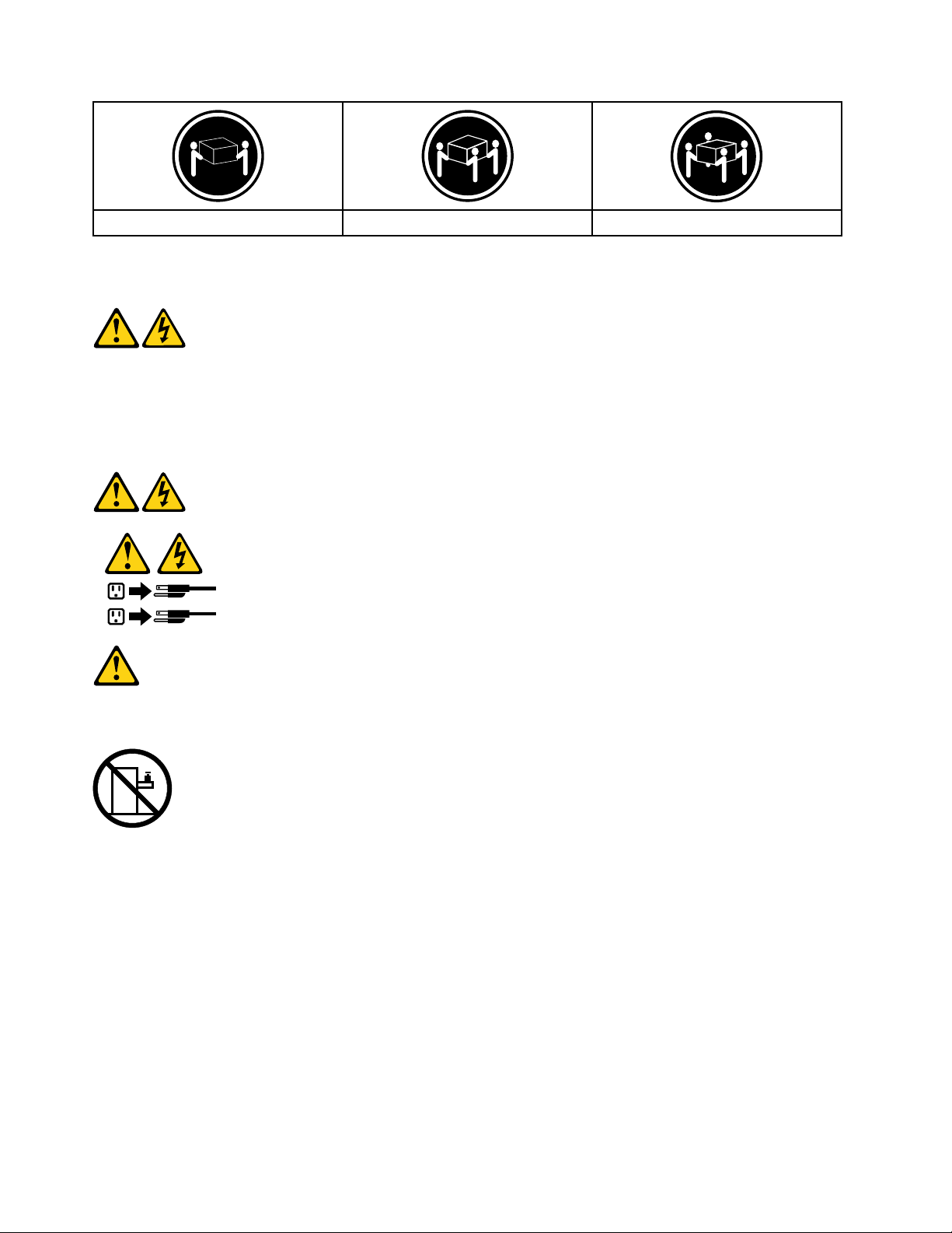
≥18kg(37lbs)≥32kg(70.5lbs)≥55kg(121.2lbs)
1
2
CAUTION:
Usesafepracticeswhenlifting.
CAUTION:
Thepowercontrolbuttononthedeviceandthepowerswitchonthepowersupplydonotturnoff
theelectricalcurrentsuppliedtothedevice.Thedevicealsomighthavemorethanonepower
cord.Toremoveallelectricalcurrentfromthedevice,ensurethatallpowercordsaredisconnected
fromthepowersource.
CAUTION:
Donotplaceanyobjectweighingmorethan82kg(180lbs.)ontopofrack-mounteddevices.
8LenovoH515HardwareMaintenanceManual
Page 15

Chapter3.Generalinformation
Thischapterprovidesgeneralinformationthatappliestoallmachinetypessupportedbythispublication.
Specications
Thissectionliststhephysicalspecicationsforyourcomputer.
Thissectionliststhephysicalspecicationsforyourcomputer.
TypeLenovoH515
Thissectionliststhephysicalspecications.
Environment
Airtemperature:
Operating:10°to35°C
Transit:-20°to55°C
Humidity:
Operating:35%to80%
Transit:20%to90%(40°C)
Altitude:86KPato106KPa
Electricalinput:
Inputvoltage:90V-264V(AC)
Inputfrequency:47Hz-63Hz
©CopyrightLenovo2013
9
Page 16

10LenovoH515HardwareMaintenanceManual
Page 17

Chapter4.GeneralCheckout
Attention:Thedrivesinthecomputeryouareservicingmighthavebeenrearrangedorthedrivestartup
sequencechanged.Beextremelycarefulduringwriteoperationssuchascopying,saving,orformatting.
Dataorprogramscanbeoverwrittenifyouselectanincorrectdrive.
Generalerrormessagesappearifaproblemorconictisfoundbyanapplicationprogram,theoperating
system,orboth.Foranexplanationofthesemessages,refertotheinformationsuppliedwiththatsoftware
package.
Usethefollowingproceduretohelpdeterminethecauseoftheproblem:
1.Power-offthecomputerandallexternaldevices.
2.Checkallcablesandpowercords.
3.Setalldisplaycontrolstothemiddleposition.
4.Power-onallexternaldevices.
5.Power-onthecomputer.
•Lookfordisplayederrorcodes
•Lookforreadableinstructionsoramainmenuonthedisplay.
Ifyoudidnotreceivethecorrectresponse,proceedtostep6.
Ifyoudoreceivethecorrectresponse,proceedtostep7.
6.Lookatthefollowingconditionsandfollowtheinstructions:
•IfthecomputerdisplaysaPOSTerror,goto“POSTerrorcodes” .
•Ifthecomputerhangsandnoerrorisdisplayed,continueatstep7.
7.Iftheteststopsandyoucannotcontinue,replacethelastdevicetested.
©CopyrightLenovo2013
11
Page 18

12LenovoH515HardwareMaintenanceManual
Page 19

Chapter5.UsingtheSetupUtility
TheSetupUtilityprogramisusedtoviewandchangethecongurationsettingsofyourcomputer,regardless
ofwhichoperatingsystemyouareusing.However,theoperating-systemsettingsmightoverrideanysimilar
settingsintheSetupUtilityprogram.
StartingtheLenovoBIOSSetupUtilityprogram
TostarttheLenovoBIOSSetupUtilityprogram,dothefollowing:
1.Ifyourcomputerisalreadyonwhenyoustartthisprocedure,shutdowntheoperatingsystemand
turnoffthecomputer.
2.PressandholdtheF1keythenturnonthecomputer.WhentheLenovoBIOSSetupUtilityprogramis
displayed,releasetheF1key.
Note:IfaPower-OnPasswordoranAdministratorPasswordhasbeenset,theSetupUtilityprogrammenu
isnotdisplayeduntilyoutypeyourpassword.Formoreinformation,see“Usingpasswords.”
Viewingandchangingsettings
SystemcongurationoptionsarelistedintheLenovoBIOSSetupUtilityprogrammenu.T ovieworchange
settings,see“StartingtheSetupUtilityprogram.”
YoumustusethekeyboardwhenusingtheLenovoBIOSSetupUtilitymenu.Thekeysusedtoperform
varioustasksaredisplayedonthebottomofeachscreen.
Usingpasswords
YoucanusetheLenovoBIOSSetupUtilityprogramtosetpasswordstopreventunauthorizedpersons
fromgainingaccesstoyourcomputeranddata.See“StartingtheSetupUtilityprogram. ”Thefollowing
typesofpasswordsareavailable:
•AdministratorPassword
•Power-OnPassword
Youdonothavetosetanypasswordstouseyourcomputer.However,ifyoudecidetosetpasswords,read
thefollowingsections.
Passwordconsiderations
Apasswordcanbeanycombinationoflettersandnumbersupto16character(a-z,and0-9).Forsecurity
reasons,itisagoodideatouseastrongpasswordthatcannotbeeasilycompromised.Wesuggestthat
passwordsshouldfollowtheserules:
•Strongpasswordscontain7-16characters,combinelettersandnumbers.
•Donotuseyournameoryourusername.
•Donotuseacommonwordoracommonname.
•Besignicantlydifferentfromyourpreviouspassword.
Attention:AdministratorandPower-Onpasswordsarenotcasesensitive
©CopyrightLenovo2013
13
Page 20

AdministratorPassword
SettinganAdministratorPassworddetersunauthorizedpersonsfromchangingcongurationsettings.Y ou
mightwanttosetanAdministratorPasswordifyouareresponsibleformaintainingthesettingsofseveral
computers.
AfteryousetanAdministratorPassword,apasswordpromptisdisplayedeverytimeyouaccesstheLenovo
BIOSSetupUtilityprogram.
IfboththeAdministratorandPower-OnPasswordareset,youcantypeeitherpassword.However,youmust
useyourAdministratorPasswordtochangeanycongurationsettings.
Setting,changing,ordeletinganAdministratorpassword
TosetanAdministratorPassword,dothefollowing:
Note:Apasswordcanbeanycombinationoflettersandnumbersupto16character(a-z,and0-9).For
moreinformation,see“Passwordconsiderations”onpage13.
1.StarttheLenovoBIOSSetupUtilityprogram(see“StartingtheLenovoBIOSSetupUtilityprogram”on
page13).
2.FromtheSecuritymenu,selectSetAdministratorPasswordandpresstheEnterkey.
3.Thepassworddialogboxwillbedisplayed.T ypethepasswordthenpresstheEnterkey.
4.Re-typethepasswordtoconrm,thenpresstheEnterkey.Ifyoutypethepasswordcorrectly,the
passwordwillbeinstalled.
TochangeanAdministratorPassword,dothefollowing:
1.StarttheLenovoBIOSSetupUtilityprogram(see“StartingtheLenovoBIOSSetupUtilityprogram”on
page13).
2.FromtheSecuritymenu,selectSetAdministratorPasswordandpresstheEnterkey.
3.Thepassworddialogboxwillbedisplayed.T ypethecurrentpasswordthenpressEnterkey.
4.T ypethenewpassword,thenpressEnterkey.Re-typethepasswordtoconrmthenewpassword,if
youtypethenewpasswordcorrectly,thenewpasswordwillbeinstalled.ASetupNoticewilldisplay
thatchangeshavebeensaved.
TodeleteapreviouslysetAdministratorPassword,dothefollowing:
1.FromtheSecuritymenu,selectSetAdministratorPasswordandpresstheEnterkey.
2.Thepassworddialogboxwillbedisplayed.T ypethecurrentpasswordandpresstheEnterkey.
3.T odeleteanAdministratorPassword,Enterblankeldsforeachnewpasswordlineitem.Asetup
noticewilldisplaythatchangeshavebeensaved.
4.ReturntotheLenovoBIOSSetupUtilityprogrammenuandselecttheExitoption.
5.SelectSavechangesandExitfromthemenu.
Power-OnPassword
WhenaPower-OnPasswordisset,youcannotstarttheLenovoBIOSSetupUtilityprogramuntilavalid
passwordistypedfromthekeyboard.
Setting,changing,ordeletingaPower-OnPassword
Note:Apasswordcanbeanycombinationoflettersandnumbersupto16character(a-z,and0-9).
14LenovoH515HardwareMaintenanceManual
Page 21

TosetaPower-OnPassword,dothefollowing:
1.StarttheLenovoBIOSSetupUtilityprogram(See”StartingtheLenovoBIOSSetupUtilityprogram”on
page13.)
2.FromtheSecuritymenu,selectSetPower-OnPasswordandpresstheEnterkey.
3.Thepassworddialogboxwillbedisplayed.T ypethepassword,andpresstheEnterkey.
4.Re-typethepasswordtoconrm,ifyoutypethepasswordcorrectly,thepasswordwillbeinstalled.
TochangeaPower-OnPassword,dothefollowing:
1.StarttheLenovoBIOSSetupUtilityprogram(See”StartingtheLenovoBIOSSetupUtilityprogram”on
page13.)
2.FromtheSecuritymenu,selectSetPower-OnPasswordandpresstheEnterkey.
3.Thepassworddialogboxwillbedisplayed.T ypethecurrentpasswordthenpresstheEnterkey.
4.T ypethenewpassword,thenpresstheEnterkey.Re-typethepasswordtoconrmthenewpassword,
ifyoutypethenewpasswordcorrectly,thenewpasswordwillbeinstalled.Asetupnoticewilldisplay
thatchangeshavebeensaved.
TodeleteapreviouslysetPower-OnPassword,dothefollowing:
1.FromtheSecuritymenu,selectSetPower-OnPasswordandpresstheEnterkey.
2.Thepassworddialogboxwillbedisplayed.T ypethecurrentpasswordandpresstheEnterkey.
3.T odeletethePower-OnPassword,Enterblankeldsforeachnewpasswordlineitem.Asetup
noticewilldisplaythatchangeshavebeensaved.
4.ReturntotheLenovoBIOSSetupUtilityprogrammenuandselecttheExitoption.
5.SelectSavechangesandExitfromthemenu.
Enablingordisablingadevice
TheDevicesoptionsisusedtoenableordisableuseraccesstothefollowingdevices:
SerialPortSetupSelectthisoptiontoenableordisableSerialPort(com).
USBFunctionsSelectwhethertoenableordisableUSB(UniversalSerial
Bus)functions.Ifitisdisabled,theUSBkeyboardand/or
USBmousemaybenotabletobeusedwithoutdevice
driversupport.
ATADriveSetupSelectIDE,ACHImodeordisableSATAcontroller.Device
driversupportisrequiredforACHImode.Dependingon
howtheharddiskimagewasinstalled,changingthis
settingmaypreventthesystemfrombooting.
VideoSetup
Tocongurevideorelatedfunctions.Thisoptionallows
youtoconguresystem'sinitiategraphicadapterfrom
eitherIGD(IntegratedGraphicsDevice)orPEG(PCI
ExpressGraphics).KeepontheIGDenabledbasedon
thesetupoptions.
Chapter5.UsingtheSetupUtility15
Page 22

OnboardAudioControllerSelectwhethertoenableordisabletheOnboardAudio
Controller,whenfeatureissettoDisabledalldevices
connectedtotheaudioconnectors(e.g.aheadphoneor
amicrophone)aredisabledandcan’tbeused.
OnboardEthernetControllerorLANBootAgentSelectwhethertoenableordisableOnboardEthernet
Controller,orselectwhethertoenableordisableload
onboardPXE(PrebootExecutionEnvironment),or
SMC(SecureManagedClient).Thisfeaturewillallow
thecomputertobootfromaserverimage.
Toenableordisableadevice,dothefollowing:
1.StarttheSetupUtilityprogram(see“StartingtheSetupUtilityprogram”onpage13).
2.FromtheSetupUtilityprogrammenu,selectDevices.
3.Select:
SerialPortSetuppresstheEnterkey,andthenselectSerialPortSetup.
USBSetuppresstheEnterkey,andthenselectUSBFunctions.
ATADeviceSetuppresstheEnterkey.SelectCongureSA T Aas,presstheEnterkeyandthen
selectSA T Amode.
VideoSetuppresstheEnterkey,andthenselectVideoSetup.
AudioSetuppresstheEnterkey,andthenselectOnboardAudioController.
NetworkSetuppresstheEnterkey,thenselectOnboardEthernetSupportorLANBootAgent.
4.SelectDisabledorEnabledandpresstheEnterkey.
5.ReturntotheLenovoBIOSSetupUtilityprogrammenuandselecttheExitoption.
6.SelectSavechangesandExitfromthemenu.
Note:Ifyoudonotwanttosavethesettings,selectDiscardchangesandExitfromthemenu.
Selectingastartupdevice
IfyourcomputerdoesnotbootfromadevicesuchastheCD/DVD-ROMdrivediskorharddiskasexpected,
followoneoftheproceduresbelow.
Selectingatemporarystartupdevice
Usethisproceduretostartupfromanybootdevice.
Note:NotallCDs,DVDsorharddiskdrivesarebootable.
1.T urnoffyourcomputer.
2.PressandholdtheF12keythenturnonthecomputer.WhentheStartupDeviceMenuappears,
releasetheF12key.
Note:IftheStartupDeviceMenudoesnotdisplayusingthesesteps,repeatedlypressandreleasethe
F12keyratherthankeepingitpressedwhenturningonthecomputer.
3.Use↑and↓arrowstoselectthedesiredstartupdevicefromtheStartupDeviceMenuandpress
theEnterkeytobegin.
Note:SelectingastartupdevicefromtheStartupDeviceMenudoesnotpermanentlychangethe
startupsequence.
Selectingorchangingthestartupdevicesequence
16LenovoH515HardwareMaintenanceManual
Page 23

Tovieworpermanentlychangetheconguredstartupdevicesequence,dothefollowing:
1.StarttheLenovoBIOSSetupUtilityprogram(see“StartingtheLenovoBIOSSetupUtilityprogram”on
page13).
2.FromtheLenovoBIOSSetupUtilityprogrammainmenu,selecttheStartupoption.
3.PresstheEnterkey,andselectthedevicesforthePrimaryBootSequence.Readtheinformation
displayedontherightsideofthescreen.
4.Use↑and↓arrowstoselectadevice.Usethe<+>or<->keystomoveadeviceupordown.Usethe
<×>keytoexcludethedevicefromorincludethedeviceinthebootsequence.
5.ReturntotheLenovoBIOSSetupUtilityprogrammenuandselecttheExitoption.
6.SelectSavechangesandExitfromthemenu.
Notes:
a.Ifyoudonotwanttosavethesettings,selectDiscardchangesandExitfromthemenu.
b.Ifyouhavechangedthesesettingsandwanttoreturntothedefaultsettings,selectLoadOptimal
Defaultsfromthemenu.
ExitingtheLenovoBIOSSetupUtilityprogram
Afteryounishviewingorchangingsettings,presstheEsckeytoreturntotheLenovoBIOSSetupUtility
programmainmenu.Y oumighthavetopresstheEsckeyseveraltimes.Dooneofthefollowing:
•Ifyouwanttosavethenewsettings,selectSavechangesandExitfromthemenu.WhentheSave&
resetwindowshows,selecttheYesbutton,andthenpresstheEnterkeytoexittheLenovoBIOS
SetupUtilityprogram.
•Ifyoudonotwanttosavethesettings,selectDiscardchangesandExitfromthemenu.Whenthe
ResetWithoutSavingwindowshows,selecttheY esbutton,andthenpresstheEnterkeytoexitthe
SetupUtilityprogram.
Chapter5.UsingtheSetupUtility17
Page 24

18LenovoH515HardwareMaintenanceManual
Page 25

Chapter6.Symptom-to-FRUIndex
TheSymptom-to-FRUindexlistserrorsymptomsandpossiblecauses.Themostlikelycauseislistedrst.
AlwaysbeginwithChapter4,“GeneralCheckout,”onpage11.Thisindexcanalsobeusedtohelpyou
decidewhichFRUstohaveavailablewhenservicingacomputer.Ifyouareunabletocorrecttheproblem
usingthisindex,goto“Undeterminedproblems”onpage20.
Notes:
•Ifyouhavebothanerrormessageandanincorrectaudioresponse,diagnosetheerrormessagerst.
•Ifyoucannotrunthediagnostictestsoryougetadiagnosticerrorcodewhenrunningatestbutdid
receiveaPOSTerrormessage,diagnosethePOSTerrormessagerst.
•Ifyoudidnotreceiveanyerrormessagelookforadescriptionofyourerrorsymptomsintherstpartof
thisindex.
Harddiskdrivebooterror
Aharddiskdrivebooterrorcanhavethefollowingcauses.
Error
Thestartupdriveisnotincludedinthebootsequence
inconguration.
Nooperatingsysteminstalledonthebootdrive.Installanoperatingsystemonthebootdrive.
Thebootsectoronthestartupdriveiscorrupted.
Thedriveisdefective.
FRU/Action
Checkthecongurationandensurethestartupdriveis
inthebootsequence.
Thedrivemustbeformatted.Dothefollowing:
1.Attempttoback-upthedataonthefailingharddisk
drive.
2.Usetheoperatingsystemtoformattheharddisk
drive.
Replacetheharddiskdrive.
PowerSupplyProblems
Followtheseproceduresifyoususpectthereisapowersupplyproblem.
Check/VerifyFRU/Action
Checkthatthefollowingareproperlyinstalled:
•PowerCord
•On/OffSwitchconnector
•SystemBoardPowerSupplyconnectors
•Microprocessor(s)connection
Checkthepowercord.PowerCord
Checkthepower-onswitch.Power-onSwitch
Reseatconnectors
©CopyrightLenovo2013
19
Page 26

POSTerrorcodes
Eachtimeyouturnthecomputeron,itperformsaseriesofteststocheckthatthesystemisoperating
correctlyandthatcertainoptionsareset.ThisseriesoftestsiscalledthePower-OnSelf- T est,orPOST.
POSTdoesthefollowing:
•Checkssomebasicsystem-boardoperations
•Checksthatthememoryisworkingcorrectly
•Startsvideooperations
•Veriesthatthebootdriveisworking
POSTErrorMessageDescription/Action
Keyboarderror
RebootandSelectproperBootdeviceorInsertBoot
MediainselectedBootdevice
Cannotinitializethekeyboard.Makesurethekeyboard
isproperlyconnectedtothecomputerandthatnokeys
areheldpressedduringPOST.Topurposelycongure
thecomputerwithoutakeyboard,selectKeyboardless
operationinStartupoptiontoEnabled.TheBIOSthen
ignoresthemissingkeyboardduringPOST.
TheBIOSwasunabletondasuitablebootdevice.Make
surethebootdriveisproperlyconnectedtothecomputer.
Makesureyouhavebootablemediainthebootdevice.
Undeterminedproblems
1.Power-offthecomputer.
2.Removeordisconnectthefollowingcomponents(ifconnectedorinstalled)oneatatime.
a.Externaldevices(modem,printer,ormouse)
b.Extendedvideomemory
c.ExternalCache
d.ExternalCacheRAM
e.Harddiskdrive
f.Diskdrive
3.Power-onthecomputertore-testthesystem.
4.Repeatsteps1through3untilyoundthefailingdeviceorcomponent.
Ifalldevicesandcomponentshavebeenremovedandtheproblemcontinues,replacethesystemboard.
20LenovoH515HardwareMaintenanceManual
Page 27

Chapter7.Locatingconnectors,controlsandcomponents
Thissectionprovidesillustrationstohelplocatethevariousconnectors,controlsandcomponentsofthe
computer.
Fontview
Thefollowingillustrationshowsthelocationofcontrolsandcomponentsonthefrontofthecomputer.
Attention:Becarefulnottoblockanyairventsonthecomputer.Blockedairventscancauseoverheating.
1.Powerbutton5.Headphoneconnector
2.Harddiskdriveindicator6.Microphoneconnector
3.Memorycardreader(selectedmodelsonly)7.OpticalDrive(selectedmodelsonly)
4.USBconnectors
Attention:TheeffectiverangeoftheBuilt-inIREmitteris10feet(3m).
©CopyrightLenovo2013
21
Page 28

Rearview
Lenovo H515
Thefollowingillustrationshowsthelocationofconnectorsandcomponentsontherearofthecomputer.
1.On-boardVGAconnector
2.HDMIconnector(selectedmodelsonly)7.Expansioncardslots(somemodelsareequippedwith
3.USB2.0connectors
4.USB3.0connectors9.Wi-Fiantenna(selectedmodelsonly)
5.Audioconnectors
6.Powerconnector
graphicscard,USB3.0orTVtunercard)
8.Ethernetconnector
10.Cableclip
22LenovoH515HardwareMaintenanceManual
Page 29

Hardwarecomponents
Thefollowingillustrationshowsthecomponentsthatmakeupyourcomputer.
1.Microprocessorfanandheat-sink
2.Memorymodules
3.PCIexpressadaptercard7.Opticaldrive
4.PCIexpressadapterconnectors
5.Powersupply
6.Systemfan
8.Harddiskdrive
Chapter7.Locatingconnectors,controlsandcomponents23
Page 30

Identifyingpartsonthemotherboard
5 64
1
2 3 7
9
1314
10
11121516
8
B
B BB BB BB BB BB BB BB BB BB BB BB BB
Themotherboard(sometimescalledtheplanarorsystemboard)isthemaincircuitboardinyourcomputer.
Itprovidesbasiccomputingfunctionsandsupportsavarietyofdevicesthatarefactory-installedorthat
youcaninstalllater.Thefollowingillustrationshowsthelocationofconnectorsandcomponentsonthe
frontofthemotherboard.
1.Systemfanheader9.LPCdebugheader
2.ClearCMOSjumper
3.Battery
4.Microprocessorandheatsink
5.Microprocessorfanheader
6.SATAconnectors(2)14.MiniPCI-Eslot
7.Memoryslots(2)15.PCIexpressX1adapterslot
8.Harddiskdrivepowerconnector16.Frontaudioconnector
10.Frontpanelconnector
11.Systemfanheader
12.PCIexpressX16adapterslot
13.FrontUSBconnectors(2)
24LenovoH515HardwareMaintenanceManual
Page 31

Chapter8.Replacinghardware
Attention:Donotremovethecomputercoverorattemptanyrepairbeforereadingthe“Importantsafetyinformation”
intheSafetyandWarrantyGuidethatwasincludedwithyourcomputer.ToobtaincopiesoftheSafetyandWarranty
Guide,gototheSupportWebsiteat:http://consumersupport.lenovo.com.
Note:UseonlypartsprovidedbyLenovo.
Generalinformation
Pre-disassemblyinstructions
Beforeproceedingwiththedisassemblyprocedure,makesurethatyoudothefollowing:
1.T urnoffthepowertothesystemandallperipherals.
2.Unplugallpowerandsignalcablesfromthecomputer.
3.Placethesystemonaat,stablesurface.
©CopyrightLenovo2013
25
Page 32

Replacingthekeyboardandmouse
Toreplacethekeyboardandmouse
Step1.Removeanymedia(disks,CDs,DVDsormemorycards)fromthedrives,shutdowntheoperating
system,andturnoffthecomputerandallattacheddevices.
Step2.Unplugallpowercordsfromelectricaloutlets.
Step3.Disconnectallcablesattachedtothecomputer.Thisincludespowercords,input/output(I/O)
cables,andanyothercablesthatareconnectedtothecomputer.Referto“Leftandrightview”
and“Rearview”forhelpwithlocatingthevariousconnectors.
Note:Y ourkeyboardwillbeconnectedtoaUSBconnectorononesideorattherearofthe
computer.
Step4.Disconnectthedefectivekeyboardcablefromthecomputerandconnectthenewkeyboardcable
tothesameconnector.
Note:Themousecanbereplacedusingthesamemethod.
Removingthecomputercover
Attention:T urnoffthecomputerandwait3to5minutestoletitcooldownbeforeremovingthecover.
Note:Itmaybehelpfultoplacethecomputerface-downonasoftatsurfaceforthisprocedure.Lenovo
recommendsthatyouuseablanket,towel,orothersoftclothtoprotectthecomputerscreenfromscratches
orotherdamage.
Toremovethecomputercover:
Step1.Removeanymedia(disks,CDs,DVDs,ormemorycards)fromthedrives,shutdowntheoperating
system,andturnoffthecomputerandallattacheddevices.
Step2.Unplugallpowercordsfromelectricaloutlets.
Step3.Disconnectallcablesattachedtothecomputer.Thisincludespowercords,input/output(I/O)
cables,andanyothercablesthatareconnectedtothecomputer.Referto“Leftandrightview”
and“Rearview”forhelpwithlocatingthevariousconnectors.
26LenovoH515HardwareMaintenanceManual
Page 33

Step4.Removethe2screwsthatsecurethecomputercoverattherearofthechassis.
Chapter8.Replacinghardware27
Page 34

Step5.Toreinstallthecomputercover:
a.Lineupthecomputercoverwiththechassisthenslideitback.
b.Securethecomputercovertothechassiswiththescrews.
Removingthefrontbezel
Attention:T urnoffthecomputerandwait3to5minutestoletitcooldownbeforeremovingthecover.
Note:Itmaybehelpfultoplacethecomputerface-downonasoftatsurfaceforthisprocedure.Lenovo
recommendsthatyouuseablanket,towel,orothersoftclothtoprotectthecomputerscreenfromscratches
orotherdamage.
Toremovethefrontbezel:
Step1.Removeanymedia(disks,CDs,DVDs,ormemorycards)fromthedrives,shutdowntheoperating
system,andturnoffthecomputerandallattacheddevices.
Step2.Unplugallpowercordsfromelectricaloutlets.
Step3.Disconnectallcablesattachedtothecomputer.Thisincludespowercords,input/output(I/O)
cables,andanyothercablesthatareconnectedtothecomputer.Referto“Leftandrightview”
and“Rearview”forhelpwithlocatingthevariousconnectors.
Step4.Removethecomputercover.Referto“Removingthecomputercover”.
28LenovoH515HardwareMaintenanceManual
Page 35

Step5.Removethefrontbezelbyreleasingthethreeplastictabsinsidethechassisandpushingthe
bezeloutwardasshown.
Step6.Toreattachthebezel:
a.Aligntheplastictabsonthebottomofthebezelwiththecorrespondingholesinthechassis,
andthensnapitintopositionatthebottomandtopofthechassis.
Step7.Reattachthecomputercover.
Replacinganopticaldrive
Note:Forthisprocedure,ithelpstolaythecomputerat.
Toreplaceanopticaldrive:
Step1.Removeanymedia(disks,CDs,DVDs,ormemorycards)fromthedrives,shutdowntheoperating
system,andturnoffthecomputerandallattacheddevices.
Step2.Unplugallpowercordsfromelectricaloutlets.
Step3.Disconnectallcablesattachedtothecomputer.Thisincludespowercords,input/output(I/O)
cables,andanyothercablesthatareconnectedtothecomputer.Referto“Leftandrightview”
and“Rearview”forhelpwithlocatingthevariousconnectors.
Step4.Removethecomputercover.Referto“Removingthecomputercover”.
Step5.Removethefrontbezel.Referto“Removingthefrontbezel”.
Chapter8.Replacinghardware29
Page 36

Step6.Disconnectthedataandpowercablesfromtherearoftheopticaldrive.
Step7.Removethe2screwsthatsecuretheopticaldiskdrivebaytothechassis.1
Step8.Slideouttheopticaldiskdrivebay,thenliftitup.2
Step9.Toinstallthenewopticaldrive:
a.Slidethenewopticaldriveintothebayfromthebackuntilitsnapsintoposition.
b.Securetheopticaldrivetothebaywiththetwoscrews.
c.Connectthedataandpowercablestothedrive.
Step10.Reattachthefrontbezel,computercover.
Replacingtheharddiskdrive
Note:Forthisprocedure,ithelpstolaythecomputerat.
Toreplacetheharddiskdrive:
Step1.Removeanymedia(disks,CDs,DVDs,ormemorycards)fromthedrives,shutdowntheoperating
system,andturnoffthecomputerandallattacheddevices.
Step2.Unplugallpowercordsfromelectricaloutlets.
Step3.Disconnectallcablesattachedtothecomputer.Thisincludespowercords,input/output(I/O)
cables,andanyothercablesthatareconnectedtothecomputer.Referto“Leftandrightview”
and“Rearview”forhelpwithlocatingthevariousconnectors.
Step4.Removethecomputercover.Referto“Removingthecomputercover”.
30LenovoH515HardwareMaintenanceManual
Page 37

Step5.Disconnectthedataandpowercablesfromtheharddiskdrive.1
2
3
1
Step6.Removethefourscrewsthatsecuretheharddiskdrivetodrivebay.2
Step7.Removetheharddiskdrivebypullingitstraightoutofthedrivebay.3
Step8.Toinstallthenewharddiskdrive:
a.Slidethenewharddiskdriveintothedrivebay.
b.Securethenewharddiskdrivetothedrivebaywiththefourscrews.
c.Connectthepoweranddatacablestotheharddiskdrive.
Step9.Reattachthecomputercover.
Replacingamemorymodule
Note:Forthisprocedure,ithelpstolaythecomputerat.
Toreplaceanopticaldrive:
Step1.Removeanymedia(disks,CDs,DVDs,ormemorycards)fromthedrives,shutdowntheoperating
system,andturnoffthecomputerandallattacheddevices.
Step2.Unplugallpowercordsfromelectricaloutlets.
Step3.Disconnectallcablesattachedtothecomputer.Thisincludespowercords,input/output(I/O)
Step4.Removethecomputercover.Referto“Removingthecomputercover”.
Step5.Locatethememorymoduleconnectors.Referto“Locatingcomponents” .
cables,andanyothercablesthatareconnectedtothecomputer.Referto“Leftandrightview”
and“Rearview”forhelpwithlocatingthevariousconnectors.
Chapter8.Replacinghardware31
Page 38

Step6.Removethememorymodulebeingreplacedbyopeningtheretainingclipsasshown.
Step7.Positionthenewmemorymoduleoverthememoryconnector.Makesurethenotch1onthe
memorymoduleiscorrectlyalignedwiththeconnectorkey2onthesystemboard.Pushthe
memorymodulestraightdownintotheconnectoruntiltheretainingclipsclose.
Step8.Reattachthecomputercover.
Replacingthegraphiccard
Toreplacethegraphiccard:
Step1.Removeanymedia(disks,CDs,DVDs,ormemorycards)fromthedrives,shutdowntheoperating
system,andturnoffthecomputerandallattacheddevices.
Step2.Unplugallpowercordsfromelectricaloutlets.
Step3.Disconnectallcablesattachedtothecomputer.Thisincludespowercords,input/output(I/O)
cables,andanyothercablesthatareconnectedtothecomputer.Referto“Leftandrightview”
and“Rearview”forhelpwithlocatingthevariousconnectors.
Step4.Removethecomputercover.Referto“Removingthecomputercover”.
32LenovoH515HardwareMaintenanceManual
Page 39

Step5.Removethescrewthatsecuresthelatchtothechassis,1opentheadapterlatch2andremove
theadapterbypullingitstraightoutoftheadapterconnector.3
Chapter8.Replacinghardware33
Page 40

Step6.Toinstallthenewgraphiccard:
a.Installthenewadapterintothesameadapterconnector.
b.Reattachthemetalbracketbackintopositionandsecurethegraphiccardtothechassis
withthescrew.
Step7.Reattachthecomputercover.
Replacingtheheat-sinkassembly
Note:Forthisprocedure,ithelpstolaythecomputerat.
Toreplacetheheat-sink:
Step1.Removeanymedia(disks,CDs,DVDs,ormemorycards)fromthedrives,shutdowntheoperating
system,andturnoffthecomputerandallattacheddevices.
Step2.Unplugallpowercordsfromelectricaloutlets.
Step3.Disconnectallcablesattachedtothecomputer.Thisincludespowercords,input/output(I/O)
cables,andanyothercablesthatareconnectedtothecomputer.Referto“Leftandrightview”
and“Rearview”forhelpwithlocatingthevariousconnectors.
Step4.Removethecomputercover.Referto“Removingthecomputercover”.
34LenovoH515HardwareMaintenanceManual
Page 41

Step5.Disconnectthemicroprocessorfancablefromthesystemboard.
Step6.Removethe4screwsthatsecuretheheat-sinkassemblytothemotherboard.
Step7.Liftuptheheat-sinktoremoveit.
Step8.Toinstallthenewheat-sinkassembly:
a.Useathermalgreasesyringetoplacevedropsofgreaseonthetopofthemicroprocessor.
Eachdropofgreaseshouldbe0.03ml(3tickmarksonthegreasesyringe).
b.Lineupthescrewsonthenewheat-sinkwithmountingholesonthemotherboardandsecure
itwiththe4screws.
c.Reconnectthemicroprocessorfanpowercabletotheconnectoronthemotherboard.
Step9.Reattachthecomputercover.
ReplacinganIntelCPU
Note:Forthisprocedure,ithelpstolaythecomputerat.
Chapter8.Replacinghardware35
Page 42

ToreplacetheCPU
Step1.Removeanymedia(disks,CDs,DVDs,ormemorycards)fromthedrives,shutdowntheoperating
system,andturnoffthecomputerandallattacheddevices.
Step2.Unplugallpowercordsfromelectricaloutlets.
Step3.Disconnectallcablesattachedtothecomputer.Thisincludespowercords,input/output(I/O)
cables,andanyothercablesthatareconnectedtothecomputer.Referto“Leftandrightview”
and“Rearview”forhelpwithlocatingthevariousconnectors.
Step4.Removethecomputercover.Referto“Removingthecomputercover”.
Step5.Replacingtheheat-sinkassembly.Referto“Replacingtheheat-sinkassembly”.
Step6.Toremovethemicroprocessor3fromthesystemboard,pressthenslidethesmallhandleout
tospringitup.
1andopentheretainer.2
Attention:Donottouchthegoldcontactsonthebottomofthemicroprocessor.Whenhandingthe
microprocessor,touchonlythesides.
Note:Donotdropanythingontothemicroprocessorsocketwhileitisexposed.Thesocketpinsmust
bekeptascleanaspossible.
36LenovoH515HardwareMaintenanceManual
Page 43

Step7.Holdingthesidesofthemicroprocessorwithyourngers,removetheprotectivecover1that
protectsthegoldcontactsonthenewmicroprocessor.2
Step8.Holdingthesidesofthemicroprocessorwithyourngers,positionthemicroprocessorsothatthe
notchesonthemicroprocessorarealignedwiththetabsinthemicroprocessorsocket.
Important:T oavoiddamagingthemicroprocessorcontacts,keepthemicroprocessorcompletelylevel
whileinstallingitintothesocket.
Step9.Lowerthemicroprocessorstraightdownintoitssocketonthemotherboard.
Step10.Tosecurethemicroprocessorinthesocket,closethemicroprocessorretainerandlockitinto
positionwiththesmallhandle.
Step11.Useathermalgreasesyringetoplace5dropsofgreaseonthetopofthemicroprocessor.Each
dropofgreaseshouldbe0.03ml(3tickmarksonthegreasesyringe).
Step12.Reattachtheheat-sinkassemblyandthecomputercover.
ReplacinganAMDCPU
Note:Forthisprocedure,ithelpstolaythecomputerat.
ToreplacetheCPU
Step1.Removeanymedia(disks,CDs,DVDs,ormemorycards)fromthedrives,shutdowntheoperating
system,andturnoffthecomputerandallattacheddevices.
Step2.Unplugallpowercordsfromelectricaloutlets.
Chapter8.Replacinghardware37
Page 44

Step3.Disconnectallcablesattachedtothecomputer.Thisincludespowercords,input/output(I/O)
cables,andanyothercablesthatareconnectedtothecomputer.Referto“Leftandrightview”
and“Rearview”forhelpwithlocatingthevariousconnectors.
Step4.Removethecomputercover.Referto“Removingthecomputercover”.
Step5.Replacingtheheat-sinkassembly.Referto“Replacingtheheat-sinkassembly”.
Step6.Liftthesmallhandleandopentheretainer.123
Attention:Donottouchthegoldcontactsonthebottomofthemicroprocessor.Whenhandingthe
microprocessor,touchonlythesides.
38LenovoH515HardwareMaintenanceManual
Page 45

Step7.Liftthemicroprocessorstraightupandoutofthesocket.
Attention:Donottouchthegoldcontactsonthebottomofthemicroprocessor.Whenhandingthe
microprocessor,touchonlythesides.
Note:Donotdropanythingontothemicroprocessorsocketwhileitisexposed.Thesocketpinsmust
bekeptascleanaspossible.
Step8.Holdingthesidesofthemicroprocessorwithyourngers,removetheprotectivecoverthat
protectsthegoldcontactsonthenewmicroprocessor.
Step9.Holdingthesidesofthemicroprocessorwithyourngers,positionthemicroprocessorsothatthe
notchesonthemicroprocessorarealignedwiththetabsinthemicroprocessorsocket.
Important:T oavoiddamagingthemicroprocessorcontacts,keepthemicroprocessorcompletelylevel
whileinstallingitintothesocket.
Chapter8.Replacinghardware39
Page 46

Step10.Lowerthemicroprocessorstraightdownintoitssocketonthemotherboard.
Step11.Tosecurethemicroprocessorinthesocket,closethemicroprocessorretainerandlockitinto
positionwiththesmallhandle.
Step12.Useathermalgreasesyringetoplace5dropsofgreaseonthetopofthemicroprocessor.Each
dropofgreaseshouldbe0.03ml(3tickmarksonthegreasesyringe).
Step13.Reattachtheheat-sinkassemblyandthecomputercover.
Replacingthesystemfan
Toreplacethesystemfan:
Step1.Removeanymedia(disks,CDs,DVDs,ormemorycards)fromthedrives,shutdowntheoperating
system,andturnoffthecomputerandallattacheddevices.
Step2.Unplugallpowercordsfromelectricaloutlets.
Step3.Disconnectallcablesattachedtothecomputer.Thisincludespowercords,input/output(I/O)
cables,andanyothercablesthatareconnectedtothecomputer.Referto“Leftandrightview”
and“Rearview”forhelpwithlocatingthevariousconnectors.
Step4.Removethecomputercover.Referto“Removingthecomputercover”.
40LenovoH515HardwareMaintenanceManual
Page 47

Step5.Disconnectthefanpowercablefromtheconnectoronthemotherboard.
Step6.Pullthesystemfanassemblyoutofthechassis.
Chapter8.Replacinghardware41
Page 48

Step7.Toinstallthenewsystemfan:
a.Installthenewsystemfanassemblybyaligningtherubbermountsofthesystemfanassembly
withtheholesonthechassisandthenpushtherubbermountsthroughtheholes.
b.Pullonthetipsoftherubbermountsuntilthefanassemblyisinplace.
c.Connectthesystemfanpowercabletotheconnectorontheboard.
Step8.Reattachthecomputercover.
42LenovoH515HardwareMaintenanceManual
Page 49

ReplacingthePowersupply
2
3
4
1
Note:Forthisprocedure,ithelpstolaythecomputerat.
ToreplacethePowersupply:
Step1.Removeanymedia(disks,CDs,DVDs,ormemorycards)fromthedrives,shutdowntheoperating
system,andturnoffthecomputerandallattacheddevices.
Step2.Unplugallpowercordsfromelectricaloutlets.
Step3.Disconnectallcablesattachedtothecomputer.Thisincludespowercords,input/output(I/O)
cables,andanyothercablesthatareconnectedtothecomputer.Referto“Leftandrightview”
and“Rearview”forhelpwithlocatingthevariousconnectors.
Step4.Removethecomputercover.Referto“Removingthecomputercover”.
Step5.Disconnectthepowercablesfromtheconnectorsonmotherboard.1
Step6.Removethe4screwsthatsecurethePowersupplytothechassis.2
Step7.SlidethenliftthePowersupplyoutofchassis.34
Step8.Installthenewpowersupply:
a.Lineuptheholesonthenewpowersupplywithmountingholesontherearofthechassisand
secureittothechassiswiththe4screws.
b.Connectthepowercablestotheconnectorsonthemotherboard.
Step9.Reattachthecomputercover.
ReplacingtheWi-Ficard
Note:Forthisprocedure,ithelpstolaythecomputerat.
ToreplacetheWi-Ficard:
Chapter8.Replacinghardware43
Page 50

Step1.Removeanymedia(disks,CDs,DVDs,ormemorycards)fromthedrives,shutdowntheoperating
system,andturnoffthecomputerandallattacheddevices.
Step2.Unplugallpowercordsfromelectricaloutlets.
Step3.Disconnectallcablesattachedtothecomputer.Thisincludespowercords,input/output(I/O)
cables,andanyothercablesthatareconnectedtothecomputer.Referto“Leftandrightview”
and“Rearview”forhelpwithlocatingthevariousconnectors.
Step4.Removethecomputercover.Referto“Removingthecomputercover”.
Step5.Disconnectthe2antennacablesfromtheWi-Ficard.
Step6.Removethe2screwsthatsecuretheWi-Ficardtothemotherboard.
Step7.PulltheWi-Ficardupwardtoremoveitfromthecard
port.
Step8.InstallthenewWi-Ficard:
a.LineupthenewWi-Ficard,theninsertitintothesamecardport.
b.SecuretheWi-Ficardtothemotherboardwiththe2screws.
c.Connectthe2antennacablestothenewWi-Ficard.
Step9.Reattachthecomputercover.
Replacingthefrontcardreadermodule
Note:Forthisprocedure,ithelpstolaythecomputerat.
Toreplacethethefrontcardreadermodule:
Step1.Removeanymedia(disks,CDs,DVDs,ormemorycards)fromthedrives,shutdowntheoperating
system,andturnoffthecomputerandallattacheddevices.
Step2.Unplugallpowercordsfromelectricaloutlets.
44LenovoH515HardwareMaintenanceManual
Page 51

Step3.Disconnectallcablesattachedtothecomputer.Thisincludespowercords,input/output(I/O)
cables,andanyothercablesthatareconnectedtothecomputer.Referto“Leftandrightview”
and“Rearview”forhelpwithlocatingthevariousconnectors.
Step4.Removethecomputercover.Referto“Removingthecomputercover”.
Step5.Removethefrontbezel.Referto“Removingthefrontbezel”.
Step6.Disconnectthedatacablesfromtheconnectorsonmotherboard.
Step7.Removethescrewthatsecuresthefrontcardreadermoduletothechassis.
Step8.Slideoutthecardreadermoduleoutofchassis.
Step9.Installthenewfrontcardreadermodule:
a.Slidethefrontcardreadermoduleinandsecureitwithscrew.
b.Connectthedatacablestothemotherboard.
Step10.Reattachthefrontbezel,computercover.
Replacingthemotherboard
Note:Forthisprocedure,ithelpstolaythecomputerat.
Toreplacethemotherboard:
Step1.Removeanymedia(disks,CDs,DVDs,ormemorycards)fromthedrives,shutdowntheoperating
system,andturnoffthecomputerandallattacheddevices.
Step2.Unplugallpowercordsfromelectricaloutlets.
Step3.Disconnectallcablesattachedtothecomputer.Thisincludespowercords,input/output(I/O)
cables,andanyothercablesthatareconnectedtothecomputer.Referto“Leftandrightview”
and“Rearview”forhelpwithlocatingthevariousconnectors.
Step4.Removethecomputercover.Referto“Removingthecomputercover”.
Step5.Removethefrontbezel.Referto“Removingthefrontbezel”.
Step6.Removethememorymodule.Referto“Replacingamemorymodule”.
Chapter8.Replacinghardware45
Page 52

Step7.Removetheheat-sinkassembly.Referto“Replacingtheheat-sinkassembly”.
Step8.RemovetheCPU.Referto“ReplacingtheCPU”.
Step9.Removethegraphiccard.Referto“Replacingthegraphiccard”.
Step10.RemovetheWi-Ficard.Referto“ReplacingtheWi-Ficard”.
Step11.Removethesystemfan.Referto“Replacingthesystemfan”.
Step12.Disconnecttheallcablesfromtheconnectorsonmotherboard.
Step13.Removethe6screwsthatsecurethemotherboardtothechassis.
Step14.Liftupthemotherboardtoremoveit.
Step15.Installthenewmotherboard:
a.Lineuptheholesonthenewmotherboardwithmountingholesonthechassisandsecure
itwithscrews.
b.Reattachthememorymodule,Wi-Ficard,heat-sinkassemblytothenewmotherboard.
c.Connecttheallcablestothenewmotherboard.
d.Reattachtheharddiskdrive,opticaldrive,graphiccardandtheTV- T unercard.
46LenovoH515HardwareMaintenanceManual
Page 53

Step16.Reattachthecomputercover.
Chapter8.Replacinghardware47
Page 54

48LenovoH515HardwareMaintenanceManual
Page 55

Chapter9.FRUlists
Thischapterliststheinformationontheeldreplaceableunits(FRUs).
Attention:BesuretoreadandunderstandallthesafetyinformationbeforereplacinganyFRUs.
Notes:FRUsthathavea1or2intheCRUcolumnareCustomerReplaceableUnits(CRUs).
•1–identiespartsthatarefairlysimpletoreplace,requiringfewornotools.
•2–identiespartsthatareslightlymoredifculttoreplace.
•N-identiespartsthatarenottobereplacedbythecustomer.
DescriptionLenovo
Systemboard
NOKEA4-5000kabinimotherboard
W8SEA4-5000kabinimotherboard
W8PEA4-5000kabinimotherboard90002572
NOKEA6-5200kabinimotherboard
W8SEA6-5200kabinimotherboard
W8PEA6-5200kabinimotherboard90002575
NOKEE2-3000kabinimotherboard
W8SEE2-3000kabinimotherboard
W8PEE2-3000kabinimotherboard90002578
EE1-2500kabiniMP@8105E/06EN_A662(R)
EE1-2500kabiniMP@8105E/06EN_A662(R)
EE1-2500kabiniMP@8105E/06EN_A662(R)
Heat-sink
TaisolCECA022836A6AMD18WCooler
AVCZEUK00T001AMD18WCooler
Memory
MT8KTF25664AZ-1G6M12GBD3-1600Memory-HF
Mic_SD9PF J2GBD3-1600Memory
Elp_RJ2108BDBG-GN-F2GBD3-1600Memory
M378B5773DH0-CK02GBD3-1600Memory-HF
M378B5273DH0-CK04GBD3-1600Memory-HF
HMT425U6AFR6C-PB2GBD3-1600Memory-HF
HMT451U6AFR8C-PB4GBD3-1600Memory-HF
M378B5773CH0-CK02GBD3-1600MEMORY
MT8JTF51264AZ-1G6J14GBD3-1600Memory-HF
Elp_RJ4208EBBG-GN-F4GBD3L-1600Memory
P/N
90002570
90002571
90002573
90002574
90002576
90002577
90002897
90002898
90002899
31501864
31501863
1100211
1100467
1100436
1100209
1100213
1100653
1100649
1100612
1100681
1100651
©CopyrightLenovo2013
49
Page 56

Mic_SD9QVG4GBD3-1600Memory
M378B5273CH0-CK04GBD3-1600MEMORY
HMT41GU6AFR8C-PB8GBD3-1600Memory-HF
Elp_RJ4208EBBG-GN-F8GBD3L-1600Memory
MT16JTF1G64AZ-1G6E18GBD3-1600Memory-HF
M378B1G73BH0-CK08GBD3-1600Memory-HF
Harddiskdrives
WDXL500AWD2500AAKX-08ERMA0250GHardDrive-LH
Pharaoh4KST250DM000250GHardDrive-LH
WDXL500AWD5000AAKX-08ERMA0500GHardDrive-LH
Pharaoh4KST500DM002500GHardDrive-LH
XL1000SWD10EZEX-08RKKA01TBHardDrive-LH
GrenadaBPST1000DM0031TBHardDrive-LH
GrenadaST1000DM0031TBHardDrive-LH
GrenadaBPST2000DM0012TBHardDrive-LH
GrenadaST2000DM0012TBHardDrive-LH
Opticaldiskdrives
Panasonic16XSW410SA T AblackDVDROM-LH
HLDS16XDH41NSATAblackDVDROM-LH
HLDS16XDH50NSATAblackDVDROM-LH
TSST16XSH-116ABSA T AblackDVDROM-LH
PLDS16XDH-16D7SHHHSATAblackDVDROM-LH
Panasonic16XSW420SA T AblackDVDROM-LH
PLDS16XDH-16ACSHSA TAblackDVDRW-LH
HLDS16XGH82NSATAblackDVDRW-LH
TSST16XSH-216BBSA T AblackDVDRW-LH
Panasonic16XSW820SA T AblackDVDRW-LH
HLDS16XGHA2NSATAblackDVDRW-LH
Graphiccards
HD8470@1G/B/DB/HGraphicsCard
HD8470@1G/B/DB/HGraphicsCard
GeforceGT620@1G/B/DB/HGraphicsCard
GeforceGT620@1G/B/DB/HGraphicsCard
GeforceGT620@512M/B/DB/HGraphicsCard
GeforceGT620@512M/B/DB/HGraphicsCard
GeforceGT635@2G/B/DB/HGraphicsCard
Powersupply
DeltaADP-65FDBE65Wadapter36200352
LiteonP A-1650-72IA65Wadapter36200353
DELTAADP-90XDBC90Wcommonadapter®
1100652
1100611
1100647
1100648
1100669
1100217
16200245
16200176
16200247
16200178
16200292
16200293
16200182
16200294
16200184
25201489
25205039
25210649
25205041
25205800
25210758
25201626
25013549
25205040
25205799
25210650
11201621
11201622
11201101
11201619
11201615
11201616
11202027
36200415
50LenovoH515HardwareMaintenanceManual
Page 57

LiteonP A-1900-72IA90wcommonadapter®
DELTAADP-120ZBBBHTcommon120Wadapter36200439
LiteonP A-1121-04LB120wcommonadapter36200440
Wi-Ficard
LTNRTL8188CE11nSBHMCWiFicard(wowl)
LTNRTL8188EE11nHMCWiFicard
CBTAR948511nHMCWiFicard
Cardreader
BitlandRTS51797in1L_Single_CR
TaisolGL827S7in1L_Single_CR
Speaker
LenovoSpeakerM0620
Touchpad
ChiconyTGR12262.4GtouchpadBLACK
Keyboard&Mouse
LiteonSK-8861(US)2.4GKB-Black8
LiteonSK-8861(US-MY)2.4GKB-Black8
LiteonSK-8861(TW)2.4GKB-Black8
LiteonSK-8861(TH)2.4GKB-Black8
LiteonSK-8861(CS-SK)2.4GKB-Black8
LiteonSK-8861(US-IN)2.4GKB-Black8
LiteonSK-8861(RU)2.4GKB-Black8
LiteonSK-8861(GB)2.4GKB-Black8
LiteonSK-8861(Nordic)2.4GKB-Black8
LiteonSK-8861(LA)2.4GKB-Black8
LiteonSK-8861(LA-AR)2.4GKB-Black8
LiteonSK-8861(SA)2.4GKB-Black8
LiteonSK-8861(CH)2.4GKB-Black8
LiteonSK-8861(DE)2.4GKB-Black8
LiteonSK-8861(TR)2.4GKB-Black8
LiteonSK-8861(ES)2.4GKB-Black8
LiteonSK-8861(SL)2.4GKB-Black8
LiteonSK-8861(IT)2.4GKB-Black8
LiteonSK-8861(IL)2.4GKB-Black8
LiteonSK-8861(FR)2.4GKB-Black8
LiteonSK-8861(GR)2.4GKB-Black8
LiteonSK-8861(HU)2.4GKB-Black8
LiteonSK-8861(BG)2.4GKB-Black8
LiteonSK-8861(KR)2.4GKB-Black8
LiteonSK-8861(JP)2.4GKB-Black8
36200416
11200352
20200218
11200354
11201223
11201222
25013742
25210789
25209175
25209176
25209177
25209178
25209179
25209180
25209181
25209182
25209183
25209184
25209185
25209186
25209187
25209188
25209189
25209190
25209191
25209192
25209193
25209194
25209195
25209196
25209197
25209198
25209199
Chapter9.FRUlists51
Page 58

LiteonSK-8861(EN-FR)2.4GKB-Black8
LiteonSK-8861(PT)2.4GKB-Black8
LiteonSK-8861(BE-EN)2.4GKB-Black8
LiteonSK-8861(DU)2.4GKB-Black8
SunrexEKB-10YA(US)B-SilkUSBKB-L VT8
PrimaxKB4721(US)B-SilkUSBKB-L VT8
ChiconyKU-1153(US)B-SilkUSBKB-L VT8
SunrexEKB-10YA(TW)B-SilkUSBKB-L VT8
SunrexEKB-10YA(TH)B-SilkUSBKB-L VT8
SunrexEKB-10YA(CZ-SL)B-SUSBKB-L VT8
SunrexEKB-10YA(IN)B-SilkUSBKB-L VT8
SunrexEKB-10YA(RU)B-SilkUSBKB-L VT8
SunrexEKB-10YA(UK)B-SilkUSBKB-L VT8
SunrexEKB-10YA(Nordic)B-SUSBKB-LVT8
SunrexEKB-10YA(LA)B-SilkUSBKB-L VT8
SunrexEKB-10YA(AR)B-SilkUSBKB-L VT8
SunrexEKB-10YA(SW)B-SilkUSBKB-L VT8
SunrexEKB-10YA(GE)B-SilkUSBKB-L VT8
SunrexEKB-10YA(TR)B-SilkUSBKB-L VT8
SunrexEKB-10YA(SP)B-SilkUSBKB-L VT8
SunrexEKB-10YA(SL)B-SilkUSBKB-L VT8
SunrexEKB-10YA(IT)B-SilkUSBKB-L VT8
SunrexEKB-10YA(HB)B-SilkUSBKB-L VT8
SunrexEKB-10YA(FR)B-SilkUSBKB-L VT8
SunrexEKB-10YA(GK)B-SilkUSBKB-L VT8
SunrexEKB-10YA(HG)B-SilkUSBKB-L VT8
SunrexEKB-10YA(BG)B-SilkUSBKB-L VT8
SunrexEKB-10YA(HR)B-SilkUSBKB-L VT8
SunrexEKB-10YA(JP)B-SilkUSBKB-L VT8
SunrexEKB-10YA(EN-FR)B-SUSBKB-L VT8
SunrexEKB-10YA(PT)B-SilkUSBKB-L VT8
SunrexEKB-10YA(BE-EN)B-SUSBKB-L VT8
SunrexEKB-10YA(DU)B-SUSBKB-LVT8
LiteonLXH-SM-8825B-SilkMouse
ChiconyLXH-MSU-1111B-SilkMouse
SunrexLXH-EMS-10ZAB-SilkMouse
LiteonSM-8861(WW)MouseBlack
LiteonSM-8861Mouse(NoBattery)Black
LiteonSM-8861Mouse(MY)Black
LiteonSM-8861(JP)wirelessmouse
25209200
25209201
25209202
25209203
25209111
25209112
25209113
25209114
25209115
25209116
25209117
25209118
25209119
25209120
25209121
25209122
25209123
25209124
25209125
25209126
25209127
25209128
25209129
25209130
25209131
25209132
25209133
25209134
25209135
25209136
25209137
25209138
25209139
25200528
25200529
25200530
25203464
25203465
25203466
25205773
52LenovoH515HardwareMaintenanceManual
Page 59

PowerCords
US,Canada,Columbia,Mexico,Philippines,ChilePeru,Venezuela,Thainland
US,Canada,Barbados,Belize,Bolivia,CostaRica,Columbia,DominicanRepublic,Ecuador,
ElSalvador ,Guatemala,Haiti,Honduras,Jamaica,Mexico,NetherlandsAntilles,Nicaragua,
Panama,Philippines,Peru,SaudiArabia,(Trinidad&Tobago),Venezuela,(Thainland)
US,Canada,Barbados,Belize,Bolivia,CostaRica,Columbia,DominicanRepublic,Ecuador,
ElSalvador ,Guatemala,Haiti,Honduras,Jamaica,Mexico,NetherlandsAntilles,Nicaragua,
Panama,Philippines,Peru,SaudiArabia,(Trinidad&Tobago),Venezuela,(Thainland)
Australia,NewZealand31035397
Australia,NewZealand31049500
Australia,NewZealand31049520
Japan31038887
Japan31049506
Japan31049519
UK,HongKong,Singapore,Malaysia,UnitedArabEmirates,SaudiArabia,
UK,HongKong,Singapore,Malaysia,Bahrain,Bangladesh,Botswana,Burma,Brunei,
Cyprus,Ghana,Ireland,Jordan,Kenya,Kuwait,Malta,Nigeria,Oman,Qatar,UnitedArab
Emirates,TrinidadandT obago,SaudiArabia,SriLanka
Czech,France,Germany,Greece,Indonesia,Netherlands,Poland,Spain,Vietnam,Turkey,
Russia,Ukraine
Albania,Algeria,Angola,Austria,Azerbaijan,Belarus,Belgium,Bosnia,Bulgaria,Croatia,,
Cambodia,Coted'ivoire,Czech,Estonia,Egypt,Finland,France,Georgia,Germany,Greece,
Herzegovina,Hungary,Indonesia,Iceland,Kazakhstan,Kyrgyzstan,Laos,Latvia,Lebanon,
Lithuania,Luxembourg,Macao,Macedonia,Mauritius,Moldova,Morocco,Netherlands,
Norway,Poland,Portugal,(Paraguay),Romania,Spain,Sweden,Serbia,Slovakia,Slovenia,
Vietnam,Tadzhikistan,Turkmenistan,Turkey,T unisia,Russia,Ukraine,Uzbekistan,Vietnam
India31035395
Italy31039104
Italy31049504
Brazil31035828
Brazil31049505
Argentina31039100
Argentina31049507
Denmark31039101
Denmark31049503
Switzerland
Switzerland
31033857
31033858
31049517
linecord+
31039655
3pin2pin
converter
31035396
31049496
31035332
31049497
31049518
31039103
31049508
Chapter9.FRUlists53
Page 60

Israel31039107
Israel31049502
Taiwan31038885
Taiwan31049499
Korea31039106
Korea31049498
SouthAfrica
SouthAfrica
Mechanical
JTLX-328A TAFrontPanelW/Button
LSLED/switchcable_680mm
MACELX-328A T AFrontPanelW/Button
JTLX-328A TBFrontPanelW/Button
GrandsunLED/switchcable_680mm
JiahaoLED/switchcable_680mm
VGACover
HDMICover
Wi-FiCover
370mmWIFICable
500mmWIFICable
Luxshare,250mmSATAcable,2latching
Grandsun,250mmSATAcable,2latching
Luxshare,420mmSA TAcable,2latching,rightangle
Grandsun,420mmSA TAcable,2latching,rightangle
Cable_U770mm_A680mm
Cable_U770mm_A680mm
Cable_U770mm_A680mm
1.8mDVIcable31501245
LX200mmHDMItoDVI-D-Scable®
SATApowercable(300mm_300mm)
SATApowercable(300mm_300mm)
31039105
31049501
90202261
31502721
90202262
90202601
31502722
31502723
31049015
31049017
31501130
31502715
31502717
31043145
31043146
31024760
31030139
31502718
31502719
31502720
31041295
31502005
31502006
54LenovoH515HardwareMaintenanceManual
Page 61

Chapter10.Generalinformation
Thischapterprovidesgeneralinformationthatappliestoallmachinetypessupportedbythispublication.
AdditionalServiceInformation
Thischapterprovidesadditionalinformationthattheservicerepresentativemightndhelpful.
Powermanagement
Powermanagementreducesthepowerconsumptionofcertaincomponentsofthecomputersuchasthe
systempowersupply,processor,harddiskdrives,andsomemonitors.
Advancedcongurationandpowerinterface(ACPI)BIOS
AsthiscomputerhasanACPIBIOSsystem,theoperatingsystemisallowedtocontrolthepower
managementfeaturesofthecomputerandthesettingsforAdvancedPowerManagement(APM)BIOSmode
isignored.NotalloperatingsystemssupportACPIBIOSmode.
AutomaticPower-Onfeatures
TheAutomaticPower-OnfeatureswithinthePowerManagementmenuallowyoutoenableanddisable
featuresthatturnonthecomputerautomatically.
•WakeUponAlarm:Youcanspecifyadateandtimeatwhichthecomputerwillbeturnedonautomatically.
Thiscanbeeitherasingleevent,adailyeventoraweeklyevent.
•WakeUponLAN:ThisfeatureallowsLANadaptercardtowaketheSystem.
©CopyrightLenovo2013
55
 Loading...