

Lenovo Flex System x280 X6 Compute Node, Flex System x480 X6 Compute Node, Flex System x880 X6 Compute Node Installation And Service Manual
Page 1

Flex System x280 X6, x480 X6, and x880 X6 Compute
Node
Types7903and4259
Installation and Service Guide
Page 2

Page 3

Flex System x280 X6, x480 X6, and x880 X6 Compute
Node
Types7903and4259
Installation and Service Guide
Page 4

Note
Before using this information and the product it supports, read the general information in “Notices” on page 777, the
Warranty Information document, and the IBM® Safety Information and the Environmental Notices and User Guide documents on
the IBM Documentation CD.
Third Edition (April 2015)
© Copyright Lenovo 2015.
Portions © Copyright IBM Corporation 2014.
LIMITED AND RESTRICTED RIGHTS NOTICE: If data or software is delivered pursuant a General Services
Administration “GSA” contract, use, reproduction, or disclosure is subject to restrictions set forth in Contract No.
GS-35F-05925.
Page 5

Contents
Safety ...............v
Guidelines for trained service technicians ....vi
Inspecting for unsafe conditions ......vi
Guidelines for servicing electrical equipment . . vii
Safety statements ............viii
Chapter 1. Introduction ........1
Related documentation ...........2
The Lenovo Documentation CD ........3
Hardware and software requirements .....3
Using the Documentation Browser ......3
Notices and statements in this document .....4
Features and specifications..........5
What your compute node offers ........7
Reliability, availability, and serviceability features. . 10
Major components of the compute node .....10
Power, controls, and indicators ........11
Compute node controls, connectors, and LEDs. . 11
Console breakout cable .........15
Turning on the compute node .......15
Turning off the compute node .......16
System-board layouts ...........17
System-board connectors .........17
System-board jumpers ..........18
System-board LEDs...........19
System-board switches..........19
Working with scalable partitions .......22
FlexNode partitioning ..........23
Single partition considerations .......23
Chapter 2. Configuring ........25
Partitioning a multi-node complex.......25
Updating firmware and device drivers .....25
Recovering a UEFI image..........27
Configuring the compute node ........28
Using the Setup utility..........29
Nx boot failure ............35
Setting the boot protocol to boot from legacy
devices using the Setup utility .......35
Using the Boot Selection Menu program ....36
Updating the Universally Unique Identifier and
DMI/SMBIOS data ...........37
Enabling Features on Demand RAID software . . 40
Configuring a RAID array ........40
Using the LSI Logic Configuration Utility . . . 40
Features on Demand ..........41
Setting up the LAN-on-motherboard (LOM)
feature ...............42
Chapter 3. Installing the operating
system...............45
Using the ServerGuide Setup and Installation CD . 46
ServerGuide features ..........47
Typical operating-system installation .....47
Installing the operating system without using
ServerGuide .............48
Using Lenovo ServerGuide Scripting Toolkit . . . 48
Chapter 4. Accessing the IMM2 ....49
Accessing the IMM2 remotely ........49
Viewing the network access tag.......49
Logging on to the web interface ......50
IMM2 action descriptions.........51
Accessing the IMM2 using the LAN over USB
interface ...............55
Potential conflicts with the LAN over USB
interface ..............56
Resolving conflicts with the IMM2 LAN over
USB interface .............56
Configuring the LAN over USB interface . . . 56
Chapter 5. Parts listing, Types 7903
and 4259 ..............59
Chapter 6. Troubleshooting ......65
Service bulletins .............65
Diagnostic tools .............65
Light path diagnostics ..........65
IMM event log ............68
Viewing event logs through the Setup utility . . 68
Viewing event logs without restarting the
compute node ............69
Lenovo Dynamic System Analysis Preboot
diagnostic program ...........70
DSA diagnostic test results ........72
Event messages.............179
IMM messages ............179
UEFI diagnostic codes .........647
DSA messages ............667
Troubleshooting by symptom ........669
Compute node start problems .......669
Connectivity problems .........670
Hard disk drive problems ........686
Intermittent Connectivity Problems .....687
Intermittent problems .........687
Memory problems ...........688
Observable problems ..........689
Optional device and replaceable component
installation problems ..........690
Performance problems .........691
Power-on problems ..........692
Software ..............693
System Scaling Issues..........694
Undetermined problems.........695
Solving undetermined problems .......696
Collecting service data ..........697
© Lenovo 2015. Portions © IBM Corp. 2014. iii
Page 6

Chapter 7. Installing, removing, and
replacing compute node components . 699
Installing an optional device ........699
Installation guidelines ..........699
System reliability guidelines .......700
Handling static-sensitive devices ......700
Returning a device or component .....700
Updating the compute node configuration. . . 700
Removing a compute node from a chassis ....701
Installing a compute node in a chassis .....702
Removing and replacing Tier 1 customer
replaceable units (CRUs) .........704
Removing the adapter-retention assembly . . . 704
Installing the adapter-retention assembly . . . 705
Removing the bezel ..........707
Installing the bezel ..........707
Removing the center partition .......708
Installing the center partition .......709
Removing the chassis bulkhead ......710
Installing the chassis bulkhead ......711
Removing the CMOS battery .......712
Installing the CMOS battery .......713
Removing the compute node cover .....715
Installing the compute node cover .....716
Removing a DIMM ..........717
Installing a DIMM...........719
Removing a fabric connector .......728
Installing a fabric connector .......729
Removing a flash DIMM ........730
Installing a flash DIMM .........730
Removing the front handle ........735
Installing the front handles ........736
Removing the hard disk drive cage and
backplane assembly ..........737
Installing the hard disk drive cage and
backplane assembly ..........738
Removing a hot-swap hard disk drive ....739
Installing a hot-swap hard disk drive ....740
Removing an I/O expansion adapter ....741
Installing an I/O expansion adapter .....742
Removing the light path diagnostics panel . . 743
Installing the light path diagnostics panel . . . 744
Removing an SMP expansion connector . . . 745
Installing an SMP expansion connector ....747
Removing a solid state drive .......750
Installing a solid state drive .......751
Removing the solid state drive cage and
backplane .............752
Installing the solid state drive cage and
backplane .............753
Removing the solid state drive mounting sleeve 755
Installing the solid state drive mounting sleeve 755
Removing the USB flash drive.......756
Installing the USB flash drive .......757
Removing and replacing FRUs (trained service
technician only) ............758
Removing a microprocessor and heat sink. . . 758
Installing a microprocessor and heat sink . . . 762
Thermal grease ............766
Removing the system-board components for
base-assembly replacement ........767
Installing the system-board components for
base-assembly replacement ........769
Appendix. Getting help and technical
assistance.............773
Before you call .............773
Using the documentation .........774
Getting help and information from the World Wide
Web................774
How to send DSA data ..........774
Creating a personalized support web page . . . 775
Software service and support ........775
Hardware service and support .......775
Taiwan product service ..........775
Notices ..............777
Trademarks ..............778
Important notes ............778
Recycling information ..........779
Particulate contamination .........779
Telecommunication regulatory statement ....780
Electronic emission notices .........780
Federal Communications Commission (FCC)
statement..............780
Industry Canada Class A emission compliance
statement..............780
Avis de conformité à la réglementation
d'Industrie Canada ..........781
Australia and New Zealand Class A statement 781
European Union EMC Directive conformance
statement..............781
Germany Class A statement .......781
Japan VCCI Class A statement.......782
Japan Electronics and Information Technology
Industries Association (JEITA) statement . . . 782
Korea Communications Commission (KCC)
statement..............783
Russia Electromagnetic Interference (EMI) Class
A statement .............783
People's Republic of China Class A electronic
emission statement ..........783
Taiwan Class A compliance statement ....783
Index ...............785
iv
Flex System x280 X6, x480 X6, and x880 X6 Compute Node Types 7903 and 4259: Installation and Service Guide
Page 7

Safety
Before installing this product, read the Safety Information.
Antes de instalar este produto, leia as Informações de Segurança.
Pred instalací tohoto produktu si prectete prírucku bezpecnostních instrukcí.
Læs sikkerhedsforskrifterne, før du installerer dette produkt.
Lees voordat u dit product installeert eerst de veiligheidsvoorschriften.
Ennen kuin asennat tämän tuotteen, lue turvaohjeet kohdasta Safety Information.
Avant d'installer ce produit, lisez les consignes de sécurité.
Vor der Installation dieses Produkts die Sicherheitshinweise lesen.
Prima di installare questo prodotto, leggere le Informazioni sulla Sicurezza.
© Lenovo 2015. Portions © IBM Corp. 2014. v
Page 8

Les sikkerhetsinformasjonen (Safety Information) før du installerer dette produktet.
Antes de instalar este produto, leia as Informações sobre Segurança.
Antes de instalar este producto, lea la información de seguridad.
Läs säkerhetsinformationen innan du installerar den här produkten.
Bu ürünü kurmadan önce güvenlik bilgilerini okuyun.
Guidelines for trained service technicians
This section contains information for trained service technicians.
Inspecting for unsafe conditions
Use this information to help you identify potential unsafe conditions in a device
that you are working on.
Each device, as it was designed and manufactured, has required safety items to
protect users and service technicians from injury. The information in this section
addresses only those items. Use good judgment to identify potential unsafe
conditions that might be caused by unsupported alterations or attachment of
unsupported features or optional devices that are not addressed in this section. If
vi Flex System x280 X6, x480 X6, and x880 X6 Compute Node Types 7903 and 4259: Installation and Service Guide
Page 9

you identify an unsafe condition, you must determine how serious the hazard is
and whether you must correct the problem before you work on the product.
Consider the following conditions and the safety hazards that they present:
v Electrical hazards, especially primary power. Primary voltage on the frame can
cause serious or fatal electrical shock.
v Explosive hazards, such as a damaged CRT face or a bulging capacitor.
v Mechanical hazards, such as loose or missing hardware.
To inspect the product for potential unsafe conditions, complete the following
steps:
1. Make sure that the power is off and the power cords are disconnected.
2. Make sure that the exterior cover is not damaged, loose, or broken, and observe
any sharp edges.
3. Check the power cords:
v Make sure that the third-wire ground connector is in good condition. Use a
meter to measure third-wire ground continuity for 0.1 ohm or less between
the external ground pin and the frame ground.
v Make sure that the power cords are the correct type.
v Make sure that the insulation is not frayed or worn.
4. Remove the cover.
5. Check for any obvious unsupported alterations. Use good judgment as to the
safety of any unsupported alterations.
6. Check inside the system for any obvious unsafe conditions, such as metal
filings, contamination, water or other liquid, or signs of fire or smoke damage.
7. Check for worn, frayed, or pinched cables.
8. Make sure that the power-supply cover fasteners (screws or rivets) have not
been removed or tampered with.
Guidelines for servicing electrical equipment
Observe these guidelines when you service electrical equipment.
v Check the area for electrical hazards such as moist floors, nongrounded power
extension cords, and missing safety grounds.
v Use only approved tools and test equipment. Some hand tools have handles that
are covered with a soft material that does not provide insulation from live
electrical current.
v Regularly inspect and maintain your electrical hand tools for safe operational
condition. Do not use worn or broken tools or testers.
v Do not touch the reflective surface of a dental mirror to a live electrical circuit.
The surface is conductive and can cause personal injury or equipment damage if
it touches a live electrical circuit.
v Some rubber floor mats contain small conductive fibers to decrease electrostatic
discharge. Do not use this type of mat to protect yourself from electrical shock.
v Do not work alone under hazardous conditions or near equipment that has
hazardous voltages.
v Locate the emergency power-off (EPO) switch, disconnecting switch, or electrical
outlet so that you can turn off the power quickly in the event of an electrical
accident.
v Disconnect all power before you perform a mechanical inspection, work near
power supplies, or remove or install main units.
Safety vii
Page 10

v Before you work on the equipment, disconnect the power cord. If you cannot
disconnect the power cord, have the customer power-off the wall box that
supplies power to the equipment and lock the wall box in the off position.
v Never assume that power has been disconnected from a circuit. Check it to
make sure that it has been disconnected.
v If you have to work on equipment that has exposed electrical circuits, observe
the following precautions:
– Make sure that another person who is familiar with the power-off controls is
near you and is available to turn off the power if necessary.
– When you work with powered-on electrical equipment, use only one hand.
Keep the other hand in your pocket or behind your back to avoid creating a
complete circuit that could cause an electrical shock.
– When you use a tester, set the controls correctly and use the approved probe
leads and accessories for that tester.
– Stand on a suitable rubber mat to insulate you from grounds such as metal
floor strips and equipment frames.
v Use extreme care when you measure high voltages.
v To ensure proper grounding of components such as power supplies, pumps,
blowers, fans, and motor generators, do not service these components outside of
their normal operating locations.
v If an electrical accident occurs, use caution, turn off the power, and send another
person to get medical aid.
Safety statements
These statements provide the caution and danger information that is used in this
documentation.
Important:
Each caution and danger statement in this documentation is labeled with a
number. This number is used to cross reference an English-language caution or
danger statement with translated versions of the caution or danger statement in
the Safety Information document.
For example, if a caution statement is labeled Statement 1, translations for that
caution statement are in the Safety Information document under Statement 1.
Be sure to read all caution and danger statements in this documentation before you
perform the procedures. Read any additional safety information that comes with
your system or optional device before you install the device.
viii Flex System x280 X6, x480 X6, and x880 X6 Compute Node Types 7903 and 4259: Installation and Service Guide
Page 11

Statement 1
DANGER
Electrical current from power, telephone, and communication cables is
hazardous.
To avoid a shock hazard:
v Do not connect or disconnect any cables or perform installation,
maintenance, or reconfiguration of this product during an electrical storm.
v Connect all power cords to a properly wired and grounded electrical outlet.
v Connect to properly wired outlets any equipment that will be attached to
this product.
v When possible, use one hand only to connect or disconnect signal cables.
v Never turn on any equipment when there is evidence of fire, water, or
structural damage.
v Disconnect the attached power cords, telecommunications systems,
networks, and modems before you open the device covers, unless
instructed otherwise in the installation and configuration procedures.
v Connect and disconnect cables as described in the following table when
installing, moving, or opening covers on this product or attached devices.
To Connect: To Disconnect:
1. Turn everything OFF.
2. First, attach all cables to devices.
3. Attach signal cables to connectors.
4. Attach power cords to outlet.
5. Turn device ON.
1. Turn everything OFF.
2. First, remove power cords from outlet.
3. Remove signal cables from connectors.
4. Remove all cables from devices.
Safety ix
Page 12

Statement 2
CAUTION:
When replacing the lithium battery, use only Part Number 33F8354 or an
equivalent type battery recommended by the manufacturer. If your system has a
module containing a lithium battery, replace it only with the same module type
made by the same manufacturer. The battery contains lithium and can explode if
not properly used, handled, or disposed of.
Do not:
v Throw or immerse into water
v Heat to more than 100°C (212°F)
v Repair or disassemble
Dispose of the battery as required by local ordinances or regulations.
Statement 12
CAUTION:
The following label indicates a hot surface nearby.
Statement 21
CAUTION:
Hazardous energy is present when the blade is connected to the power source.
Always replace the blade cover before installing the blade.
UL regulatory information
This device is for use only with Listed Flex System Enterprise Chassis.
x Flex System x280 X6, x480 X6, and x880 X6 Compute Node Types 7903 and 4259: Installation and Service Guide
Page 13

Chapter 1. Introduction
The IBM Flex System x280 X6, x480 X6, and x880 X6 Compute Node Types 7903
and 4259 is a high-availability, scalable compute node that is optimized to support
the next-generation microprocessor technology and is ideally suited for medium
and large businesses.
The Flex System x280 X6, x480 X6, and x880 X6 Compute Node Types 7903 and
4259 is supported in the Flex System Enterprise Chassis only.
The Flex System x280 X6, x480 X6, and x880 X6 Compute Node Types 7903 and
4259 is functionally identical except for the scaling capabilities of the
microprocessor family.
Table 1. Compute node scaling capabilities
Compute node Scaling capability Microprocessor family
Flex System x280 X6 One-node configurations
Flex System x480 X6 One-node and two-node
Flex System x880 X6 One-node, two-node, and
2800
only
4800
configurations
8800
four-node configurations
The scaling capabilities of the Flex System x280 X6, x480 X6, and x880 X6 Compute
Node Types 7903 and 4259 allows you to form a scalable partition. Combining the
compute nodes in a scalable partition provides for FlexNode partitioning. With
FlexNode partitioning, you can toggle between a single partition or multiple
partitions without having to modify the physical setup of the compute nodes. For
more information about scalable partitions and FlexNode partitioning, see
“Working with scalable partitions” on page 22.
This documentation provides the following information about setting up and
troubleshooting the compute node:
v Starting and configuring the compute node
v Installing the operating system
v Diagnosing problems
v Installing, removing, and replacing components
Packaged with the compute node are software CDs that help you configure
hardware, install device drivers, and install the operating system.
To download the latest firmware and device drivers, go to http://www.ibm.com/
support/fixcentral and select Flex System and Flex System x280 X6, x480 X6, and
x880 X6.
The compute node comes with a limited warranty. For information about the terms
of the warranty and getting service and assistance, see the Warranty Information
document for your compute node. This document is available on the Documentation
CD.
© Lenovo 2015. Portions © IBM Corp. 2014. 1
Page 14

You can obtain up-to-date information about the compute node at
http://www.ibm.com/systems.
The compute node might have features that are not described in the
documentation that comes with the compute node. The documentation might be
updated occasionally to include information about those features. Technical
updates might also be available to provide additional information that is not
included in the compute node documentation. To obtain the most up-to-date
documentation for this product, go to http://pic.dhe.ibm.com/infocenter/flexsys/
information/index.jsp.
You can subscribe to information updates that are specific to your compute node at
http://www.ibm.com/support/mynotifications.
The model number and serial number are on the ID label on the bezel on the front
of the compute node, and on a label on the bottom of the compute node that is
visible when the compute node is not in the Flex System chassis. If the compute
node comes with an RFID tag, the RFID tag covers the ID label on the bezel on the
front of the compute node but you can open the RFID tag to see the ID label
behind it.
Note: The illustrations in this document might differ slightly from your hardware.
ID label
RFID tag
Related documentation
Use this information to identify and locate related compute node documentation.
This Installation and Service Guide contains general information about the compute
node, including how to install supported optional devices and how to configure
the compute node. It also contains information to help you solve problems yourself
and instructions for removing and installing components, and it contains
information for service technicians. Documents that are in Portable Document
Format (PDF) are on the documentation CD that comes with your product. The
following documentation is also available.
v Safety Information
2 Flex System x280 X6, x480 X6, and x880 X6 Compute Node Types 7903 and 4259: Installation and Service Guide
Page 15

This document is in PDF. It contains translated caution and danger statements.
Each caution and danger statement that appears in the documentation has a
number that you can use to locate the corresponding statement in your language
in the Safety Information document.
v Lenovo Warranty Information
This printed document contains the warranty terms and a pointer to the Lenovo
Statement of Limited Warranty.
v Environmental Notices and User Guide
This document is in PDF. It contains translated environmental notices.
v License Agreement for Machine Code
This document is in PDF. It provides translated versions of the Lenovo License
Agreement for Machine code for your compute node.
v Licenses and Attributions Document
This document is in PDF. It provides information about the open-source notices.
In addition to the documentation in this library, be sure to review the Installation
and Service Guide for your Flex System chassis for information to help you prepare
for system installation and configuration.
To check for updated documentation, go to http://www.ibm.com/supportportal.
You can also find documentation that is related to Flex System products at
http://pic.dhe.ibm.com/infocenter/flexsys/information/index.jsp.
The Lenovo Documentation CD
The Documentation CD contains documentation for the compute node in Portable
Document Format (PDF). It includes a documentation browser to help you find
information quickly.
You can run the Documentation CD on any computer that meets the hardware and
software requirements.
Hardware and software requirements
Use this information to determine the minimum hardware and software
requirements.
The Lenovo Documentation CD requires the following minimum hardware and
software:
v Microsoft Windows
v 100 MHz microprocessor
v 32 MB of RAM
v Adobe Acrobat Reader 3.0 (or later) or xpdf, which comes with Linux operating
systems
Using the Documentation Browser
Use this information to start the Documentation Browser.
Use the Documentation Browser to browse the contents of the CD, read brief
descriptions of the documents, and view documents, using Adobe Acrobat Reader
or xpdf. The Documentation Browser automatically detects the regional settings in
Chapter 1. Introduction 3
Page 16

use in your system and displays the documents in the language for that region (if
available). If a document is not available in the language for that region, the
English-language version is displayed.
Use one of the following procedures to start the Documentation Browser:
v If Autostart is enabled, insert the CD into the CD or DVD drive. The
Documentation Browser starts automatically.
v If Autostart is disabled or is not enabled for all users, use one of the following
procedures:
– If you are using a Windows operating system, insert the CD into the CD or
DVD drive and click Start → Run.IntheOpen field, type
e:\win32.bat
where e is the drive letter of the CD or DVD drive, and click OK.
– If you are using Red Hat Linux, insert the CD into the CD or DVD drive;
then, run the following command from the /mnt/cdrom directory:
sh runlinux.sh
Select the compute node from the Product menu. The Available Topics list
displays all the documents for the compute node. Some documents might be in
folders. A plus sign (+) indicates each folder or document that has additional
documents under it. Click the plus sign to display the additional documents.
When you select a document, a description of the document is displayed under
Topic Description. To select more than one document, press and hold the Ctrl key
while you select the documents. Click View Book to view the selected document
or documents in Acrobat Reader or xpdf. If you selected more than one document,
all the selected documents are opened in Acrobat Reader or xpdf.
To search all the documents, type a word or word string in the Search field and
click Search. The documents in which the word or word string appears are listed
in order of the most occurrences. Click a document to view it. Press Ctrl+F to use
the Acrobat search function, or press Alt+F to use the xpdf search function within
the document.
Click Help for detailed information about using the Documentation Browser.
Notices and statements in this document
Use this information to understand the most common documentation notices and
statements and how they are used.
The caution and danger statements in this document are also in the multilingual
Safety Information document, which is on the Documentation CD. Each statement is
numbered for reference to the corresponding statement in the Safety Information
document.
The following notices and statements are used in this document:
v Note: These notices provide important tips, guidance, or advice.
v Important: These notices provide information or advice that might help you
avoid inconvenient or problem situations.
v Attention: These notices indicate possible damage to programs, devices, or data.
An attention notice is placed just before the instruction or situation in which
damage might occur.
4 Flex System x280 X6, x480 X6, and x880 X6 Compute Node Types 7903 and 4259: Installation and Service Guide
Page 17

v Caution: These statements indicate situations that can be potentially hazardous
to you. A caution statement is placed just before the description of a potentially
hazardous procedure step or situation.
v Danger: These statements indicate situations that can be potentially lethal or
hazardous to you. A danger statement is placed just before the description of a
potentially lethal or hazardous procedure step or situation.
Features and specifications
Use this information to view specific information about the compute node, such as
compute node hardware features and the dimensions of the compute node.
Notes:
1. Power, cooling, and chassis systems management are provided by the Flex
System chassis.
2. The operating system in the compute node must provide USB support for the
compute node to recognize and use USB media drives and devices.
The following is a summary of the features and specifications of the Flex System
x280 X6, x480 X6, and x880 X6 compute node.
Microprocessor:
Two multi-core Intel Xeon microprocessors.
Note: Use the Setup utility to determine the type and speed of the
microprocessors in the compute node.
Integrated functions:
v Renesas SH7757 (IMM2) baseboard management controller (BMC) with
integrated VGA controller
v (Models with LAN-on-motherboard (LOM) only) Two LOM fabric
connectors and one Emulex Skyhawk Quad-Port 10 Gigabit Ethernet
controller
v Support for up to two internal USB ports
v One external USB port
v One LSI 3004 SAS controller with support for RAID level-0 or RAID
level-1
v Light path diagnostics
v Automatic server restart (ASR)
v (Models without LOM) Four I/O expansion connectors
v (Models with LOM) Support for two I/O expansion connectors
v Serial over LAN (SOL)
v Wake on LAN (WOL)
v Wake on PCI (PME) capability
v Built-in monitoring for temperature, voltage, and hard disk drives
v Advanced Configuration and Power Interface (ACPI)
Upgradeable firmware:
All firmware is field upgradeable.
Memory:
v 48 dual inline memory module (DIMM) connectors
v Type: Low-profile (LP) double-data rate (DDR3) DRAM
v Supports 4 GB, 8 GB, 16 GB, 32 GB, and 64 GB DIMMs with up to 3 TB
of total memory on the system board per compute node
v Support for RDIMMs and LRDIMMs (combining is not supported)
v Vital product data (VPD)
Chapter 1. Introduction 5
Page 18

Drives:
v Support for up to two 2.5-inch hot-swap, small form factor (SFF) Serial
Attached SCSI (SAS) or Serial ATA (SATA) hard disk drives, or up to
two 2.5-inch hot-swap solid state drives (SSDs)
v Optional support for up to four 1.8-inch hot-swap SSDs
v Optional RAID controller supports up to four 1.8-inch hot-swap SSDs
and up to four non-hot-swap 1.8-inch SSDs
Flash DIMMs:
Supports a maximum of 16 DDR3 flash DIMMs in 200 GB or 400 GB
capacities.
Scalability:
Supports scaling to form two-node or four-node complexes, providing up
to eight microprocessor sockets and 192 DIMM connectors.
Predictive Failure Analysis (PFA) alerts:
v Microprocessors
v Memory
v Hard disk drives
Size:
v Height: 55.5 mm (2.19 in)
v Depth: 500 mm (19.7 in)
v Width: 435.3 mm (17.14 in)
v Maximum weight: 12.25 kg (27 lbs)
Security:
Fully compliant with NIST 800-131A. The security cryptography mode set
by the managing device (CMM or Flex System Manager management
node) determines the security mode in which the compute node operates.
Environment:
The Flex System x280 X6, x480 X6, and x880 X6 Compute Node Types 7903
and 4259 complies with ASHRAE class A3 specifications.
v Power on
– Temperature: 5°C - 40°C (41°F - 104°F) up to 950m (3,117ft)
– Humidity, non-condensing: -12°C dew point (10.4°F) and 8% - 85%
– Maximum dew point: 24°C (75°F)
– Maximum altitude: 3048 m (10,000 ft)
– Maximum rate of temperature change: 5°C/hr (41°F/hr )
v Power off2:
– Temperature: 5°C to 45°C (41°F - 113°F)
– Relative humidity: 8% - 85%
– Maximum dew point: 27°C (80.6°F)
v Storage (non-operating):
– Temperature: 1°C to 60°C (33.8°F - 140°F)
– Altitude: 3050 m (10,006 ft)
– Relative humidity: 5% - 80%
– Maximum dew point: 29°C (84.2°F)
v Shipment (non-operating)
– Temperature: -40°C to 60°C (-40°F - 140°F)
– Altitude: 10,700 m (35,105 ft)
1
:
relative humidity
5,6
3
4
7
:
6 Flex System x280 X6, x480 X6, and x880 X6 Compute Node Types 7903 and 4259: Installation and Service Guide
Page 19

– Relative humidity: 5% - 100%
– Maximum dew point: 29°C (84.2°F)
8
v Particulate contamination
Attention: Airborne particulates and reactive gases acting alone or in
combination with other environmental factors such as humidity or
temperature might pose a risk to the compute node. For information
about the limits for particulates and gases, see “Particulate
contamination” on page 779.
1. Compute Node powered on.
2. Compute Node is removed from original shipping container and is
installed but not in use, for example, during repair, maintenance, or
upgrade.
3. A3 - Derate maximum allowable temperature 1°C/175 m above 950 m.
At maximum altitude of 3,050m (10kft) maximum air temperature is
28°C (82°F)
4. 5°C/hr for data centers employing tape drives and 20°C/hr for data
centers employing disk drives.
5. The minimum humidity level for class A3 is the higher (more moisture)
of the -12 °C dew point and the 8% relative humidity. These intersect at
approximately 25°C. Below this intersection (~25C), the dew point (-12
°C) represents the minimum moisture level; above the intersection,
relative humidity (8%) is the minimum.
6. Moisture levels lower than 0.5°C DP, but not lower -10 °C DP or 8%
relative humidity, can be accepted if appropriate control measures are
implemented to limit the generation of static electricity on personnel
and equipment in the data center. All personnel and mobile furnishings
and equipment must be connected to ground via an appropriate static
control system. The following items are considered the minimum
requirements:
a. Conductive materials (conductive flooring, conductive footwear on
all personnel who go into the datacenter; all mobile furnishings and
equipment will be made of conductive or static dissipative
materials).
b. During maintenance on any hardware, a properly functioning wrist
strap must be used by any personnel who contacts IT equipment.
7. The equipment acclimation period is 1 hour per 20°C of temperature
change from the shipping environment to the operating environment.
8. Condensation is acceptable, but not rain.
9. The fully configured chassis weight is based on all nodes and I/O
modules being at their maximum design limit.
What your compute node offers
Your compute node offers features such as the integrated management module II,
hard disk drive support, systems-management support, microprocessor technology,
integrated network support, I/O expansion, large system-memory capacity, light
path diagnostics, PCI Express, and power throttling.
v Features on Demand
If a Features on Demand feature is integrated in the compute node or in an
optional device that is installed in the compute node, you can purchase an
Chapter 1. Introduction 7
Page 20

activation key to activate the feature. For information about Features on
Demand, see http://www.ibm.com/systems/x/fod/.
v Flash DIMM support
The compute node supports a maximum of 16 DDR3 flash DIMMs in 200 GB or
400 GB capacities. The flash DIMMs utilize the unpopulated DIMM slots
available in the compute node and provide high performance solid state
memory. The flash DIMMs can be used for storage or storage cache.
v Flexible network support
The compute node provides flexible network capabilities:
– Models with embedded virtual fabric: The integrated Emulex Skyhawk
Quad-Port 10 Gigabit Ethernet controller supports connections to a 10 Mbps,
100 Mbps, or 1000 Mbps network through an Ethernet-compatible switch
module in the chassis. The controller supports connections at 10 Gb. The
controller also supports Wake on LAN technology. You can install up to two
additional I/O expansion adapters for network support.
– Models without embedded virtual fabric: The compute node has connectors
on the system board for optional expansion adapters for adding network
communication capabilities to the compute node. You can install up to four
I/O expansion adapters for network support. This provides the flexibility to
install expansion adapters that support a variety of network communication
technologies.
v Hard disk drive support
The compute node supports up to two hot-swap hard disk drives, with optional
support for up to four hot-swap solid state drives (SSDs). You can implement
RAID 0 or RAID 1 for the drives. An optional RAID controller supports up to
four hot-swap SSDs and up to four non-hot-swap SSDs.
v Lenovo ServerGuide Setup and Installation CD
The ServerGuide Setup and Installation CD, which you can download from the
web, provides programs to help you set up the compute node and install a
Windows operating system. The ServerGuide program detects installed optional
hardware devices and provides the correct configuration programs and device
drivers. For more information, see “Using the ServerGuide Setup and
Installation CD” on page 46.
v Lenovo X-Architecture
Lenovo X-Architecture systems combine proven, innovative designs to make
your x86-processor-based compute node powerful, scalable, and reliable. For
more information, see http://www.ibm.com/systems/x/hardware/enterprise/.
v Integrated management module II (IMM2)
The integrated management module II (IMM2) combines systems-management
functions, video controller, the remote presence, and blue-screen capture features
in a single chip. The IMM2 provides advanced systems-management control,
monitoring, and alerting function. If an environmental condition exceeds a
threshold or if a system component fails, the IMM2 lights LEDs to help you
diagnose the problem, records the error in the IMM event log, and alerts you to
the problem.
Optionally, the IMM2 also provides a virtual presence capability for remote
systems management. The IMM2 provides remote systems management through
industry-standard interfaces:
– Common Information Model (CIM)
– Intelligent Platform Management Interface (IPMI) version 2.0
– Simple Network Management Protocol (SNMP) version 3.0
8 Flex System x280 X6, x480 X6, and x880 X6 Compute Node Types 7903 and 4259: Installation and Service Guide
Page 21

– Web browser
For more information, see Chapter 4, “Accessing the IMM2,” on page 49.
v Large system-memory capacity
The compute node supports up to 3 TB of system memory. The memory
controllers provide support for up to 48 industry-standard registered ECC DDR3
on low-profile (LP) DIMMs on the system board. For the most current list of
supported DIMMs, see http://www.ibm.com/systems/info/x86servers/
serverproven/compat/us.
v Light path diagnostics
Light path diagnostics provides light-emitting diodes (LEDs) to help you
diagnose problems. For more information, see “Light path diagnostics” on page
65.
v Microprocessor technology
The compute node supports two multi-core Intel Xeon microprocessors. For
more information about supported microprocessors, see Chapter 5, “Parts listing,
Types 7903 and 4259,” on page 59.
v PCI Express
PCI Express is a serial interface that is used for chip-to-chip interconnect and
expansion adapter interconnect. You can add optional I/O and storage devices.
v Power throttling
By enforcing a power policy known as power-domain oversubscription, the Flex
System chassis can share the power load between two or more power supply
modules to ensure sufficient power for each device in the Flex System chassis.
This policy is enforced when the initial power is applied to the Flex System
chassis or when a compute node is inserted into the Flex System chassis.
The following settings for this policy are available:
– Basic power management
– Power module redundancy
– Power module redundancy with compute node throttling allowed
You can configure and monitor the power environment by using the Chassis
Management Module. For more information, see the Flex System Chassis
Management Module: Command-Line Interface Reference Guide at
http://pic.dhe.ibm.com/infocenter/flexsys/information/topic/
com.ibm.acc.cmm.doc/dw1kt_cmm_cli_book.pdf.
v Scalable partitions
Your compute node is scalable and can be connected to multiple compute nodes
so that you can share resources between compute nodes. For more information
about scalable partitions, see “Working with scalable partitions” on page 22.
v Systems-management support
The compute node IMM2 provides a Web interface for remote
systems-management support. You can use the interface to view system status,
and control server management functions and IMM management settings.
The IMM2 communicates with the Flex System Chassis Management Module
(CMM) and Flex System Manager management software (if installed).
– CMM is a hot-swap module that provides system-management functions for
all components in an Flex System chassis. It controls a serial port for remote
connection and a 1 Gbps Ethernet remote-management connection. For more
information, see the Flex System Chassis Management Module:
Chapter 1. Introduction 9
Page 22

Command-Line Interface Reference Guide at http://pic.dhe.ibm.com/
infocenter/flexsys/information/topic/com.ibm.acc.cmm.doc/
dw1kt_cmm_cli_book.pdf.
– Flex System Manager management software is a platform-management
foundation that streamlines the way you manage physical and virtual systems
in a heterogeneous environment. By using industry standards, Flex System
Manager management software supports multiple operating systems and
virtualization technologies. For more information, see the "Flex System
Manager Software: Installation and Service Guide" at http://
pic.dhe.ibm.com/infocenter/flexsys/information/topic/
com.ibm.acc.8731.doc/product_page.html.
Reliability, availability, and serviceability features
Three of the most important features in compute node design are reliability,
availability, and serviceability (RAS). These RAS features help to ensure the
integrity of the data that is stored in the compute node, the availability of the
compute node when you need it, and the ease with which you can diagnose and
correct problems.
Many RAS-related hardware features for the compute node are listed in “Features
and specifications” on page 5. Features provided by the compute node Setup
utility, IMM2 remote chassis management, and troubleshooting tools enhance
compute node reliability, availability, and serviceability. In addition, access to a
customer support center available 24 hours per day, 7 days a week improves
compute node availability and serviceability.
1
Major components of the compute node
Use this information to locate the major components on the compute node. The
major components of the compute node include field replaceable units (FRUs),
customer replaceable units (CRUs), and optional devices.
The following illustration shows the major components of the compute node.
1. Service availability varies by country. Response time varies depending on the number and nature of incoming calls.
10 Flex System x280 X6, x480 X6, and x880 X6 Compute Node Types 7903 and 4259: Installation and Service Guide
Page 23

Heat sinks
Hard disk
drive cage and
backplane assembly
Cover
Left
air baffle
Right
air baffle
Hot-swap
hard disk
drive
Center
partition
Left
bezel
Power, controls, and indicators
Use this information to view power features, turn on and turn off the compute
node, and view the functions of the controls and indicators.
Compute node controls, connectors, and LEDs
Use this information for details about the controls, connectors, and LEDs.
SMP
filler
Right
bezel
I/O expansion
adapter
DIMM
Microprocessor
Hard disk
drive filler
panel
The following illustration identifies the buttons, connectors, and LEDs on the
control panel.
Identify
LED
Link up
LED
Check log
LED
Scaling
LED
Fault
LED
Hard disk drive
activity LED
USB
connector
Hard disk drive
status LED
0 1
KVM
connector
SMP expansion
connectors
Powe r
button/LED
Link error
LED
Hard disk drive activity LED (green)
When this green LED is lit, it indicates that the hard disk drive is powered
on. When flashing, this LED indicates that the drive is in use.
Chapter 1. Introduction 11
Page 24

Hard disk drive status LED (yellow)
When this yellow LED is lit, it indicates that an error has occurred with the
hard disk drive. The LED turns off only after the error is corrected. You
can check the CMM event log to determine the source of the condition. For
more information, see “Viewing event logs without restarting the compute
node” on page 69.
SMP expansion connectors
Use these connectors to connect the compute node to other compute nodes
to form multi-node complexes. The SMP expansion connectors come
protected by a filler that you can remove. For more information, see
“Installing an SMP expansion connector” on page 747.
Link error LED
When this yellow LED is lit, it indicates that a scalable link error occurred.
Link up LED
When this green LED is lit, it indicates that the compute node is connected
to other compute nodes through a quick path interconnect (QPI) link.
Note: When the Link error LED is lit, indicating that a scalable
partitioning error occurred, this LED is turned off.
Scaling LED
When this white LED is lit, it indicates that the compute node is part of a
scalable partition. When turned off, this LED indicates that the compute
node is operating independently.
Note: This LED is operational and can be lit when the compute node is
installed in the chassis and is connected to power, even if the compute
node is not turned on.
Fault LED
When this yellow LED is lit, it indicates that a system error has occurred in
the compute node. In addition, the fault LED on the chassis system LED
panel is lit. You can check the CMM event log to determine the source of
the condition. For more information, see “Viewing event logs without
restarting the compute node” on page 69. See also “Light path diagnostics
LEDs” on page 67 for more information about the LEDs on the compute
node.
The fault LED turns off only after the error is corrected.
Note: When the fault LED turns off, you should also clear the IMM event
log. Use the Setup utility to clear the IMM event log.
Check log LED
When this yellow LED is lit, it indicates that a condition that causes an
event to be logged in the event log has occurred. To view the IMM2 event
log see “IMM event log” on page 68
The check log LED can be turned off through the CMM led command, the
CMM web interface, or Flex System Manager management software (if
installed).
v For more information about the CMM led command, see the "Flex
System Chassis Management Module: Command-Line Interface
Reference Guide" at http://pic.dhe.ibm.com/infocenter/flexsys/
information/topic/com.ibm.acc.cmm.doc/cli_command_led.html.
12 Flex System x280 X6, x480 X6, and x880 X6 Compute Node Types 7903 and 4259: Installation and Service Guide
Page 25

v From the CMM web interface, select Compute Nodes from the Chassis
Management menu. All fields and options are described in the CMM
web interface online help. For more information, see
http://pic.dhe.ibm.com/infocenter/flexsys/information/index.jsp?topic=
%2Fcom.ibm.acc.cmm.doc%2Fcmm_product_page.html.
v For more information about Flex System Manager management software,
see the "Flex System Manager Software: Installation and Service Guide"
at http://pic.dhe.ibm.com/infocenter/flexsys/information/topic/
com.ibm.acc.8731.doc/product_page.html.
Notes:
1. Alternatively, you can use the CMM_INDICATES_ITE_ERROR_N
command to light the check log LED. See the Flex System Chassis
Management Module: Command-Line Interface Reference Guide at
http://pic.dhe.ibm.com/infocenter/flexsys/information/topic/
com.ibm.acc.cmm.doc/dw1kt_cmm_cli_book.pdf for more information.
2. You can check the CMM event log to determine the source of the
condition. For more information, see “Viewing event logs without
restarting the compute node” on page 69.
Identify LED
The system administrator can remotely light this blue LED to aid in
visually locating the compute node. When this LED is lit, the identify LED
on the Flex System chassis is also lit. The identify LED can be lit and
turned off through the CMM led command, the CMM web interface, or
Flex System Manager management software (if installed).
When this LED is lit in a scalable partition, the identify LED on all nodes
in the scalable partition are also lit.
v For more information about the CMM led command, see the "Flex
System Chassis Management Module: Command-Line Interface
Reference Guide" at http://pic.dhe.ibm.com/infocenter/flexsys/
information/topic/com.ibm.acc.cmm.doc/cli_command_led.html.
v From the CMM web interface, select Compute Nodes from the Chassis
Management menu. All fields and options are described in the CMM
web interface online help. For more information, see
http://pic.dhe.ibm.com/infocenter/flexsys/information/index.jsp?topic=
%2Fcom.ibm.acc.cmm.doc%2Fcmm_product_page.html.
v For more information about Flex System Manager management software,
see the "Flex System Manager Software: Installation and Service Guide"
at http://pic.dhe.ibm.com/infocenter/flexsys/information/topic/
com.ibm.acc.8731.doc/product_page.html.
Power button/LED
When the compute node is connected to power through the Flex System
chassis, press this button to turn on or turn off the compute node.
When you press the power-control button on any compute node in a single
partition (controlled by one operating system), all compute nodes in the
single partition will be turned on or turned off.
Note: The power button works only if local power control is enabled for
the compute node. Local power control is enabled and disabled through
the CMM power command and the CMM web interface.
v For more information about the CMM power command, see the "Flex
System Chassis Management Module: Command-Line Interface
Chapter 1. Introduction 13
Page 26

Reference Guide" at http://pic.dhe.ibm.com/infocenter/flexsys/
information/topic/com.ibm.acc.cmm.doc/cli_command_power.html.
v From the CMM web interface, select Compute Nodes from the Chassis
Management menu. For more information, see the "Flex System Chassis
Management Module: User's Guide" at http://pic.dhe.ibm.com/
infocenter/flexsys/information/topic/com.ibm.acc.cmm.doc/
cmm_user_guide.html. All fields and options are described in the CMM
web interface online help.
After the compute node is removed from the chassis, press and hold this
button to activate the system-board LEDs (light path diagnostics). See
“Compute node controls, connectors, and LEDs” on page 11 for more
information.
This button is also the power LED. This green LED indicates the power
status of the compute node:
v Flashing rapidly: The LED flashes rapidly for one of the following
reasons:
– The compute node has been installed in a chassis. When you install
the compute node, the LED flashes rapidly for up to 90 seconds while
the integrated management module II (IMM2) in the compute node is
initializing and synchronizing with the chassis management module.
– Power permissions have not been assigned to the compute node
through the Chassis Management Module.
– The Flex System chassis does not have enough power to turn on the
compute node.
– The IMM2 in the compute node is not communicating with the
Chassis Management Module.
v Flashing slowly: The compute node is connected to power through the
Flex System chassis and is ready to be turned on.
v Lit continuously: The compute node is connected to power through the
Flex System chassis and is turned on.
When the compute node is on, pressing this button causes an orderly
shutdown of the compute node so that it can be removed safely from the
chassis. This includes shutting down the operating system (if possible) and
removing power from the compute node.
If an operating system is running, you might have to press the button for
approximately 4 seconds to initiate the shutdown.
Attention: Pressing the button for 4 seconds forces the operating system to
shut down immediately. Data loss is possible.
KVM connector
Connect the console breakout cable to this connector (see “Console
breakout cable” on page 15 for more information).
Note: It is best practice to connect the console breakout cable to only one
compute node at a time in each Flex System chassis.
USB connector
Connect a USB device to this connector.
Note: It is best practice to connect a USB device to the front of only one
compute node at a time in each Flex System chassis.
14 Flex System x280 X6, x480 X6, and x880 X6 Compute Node Types 7903 and 4259: Installation and Service Guide
Page 27

Console breakout cable
Use this information for details about the console breakout cable.
Attention: Use only the console breakout cable that comes with the compute node.
Attempting to connect other console breakout cable types might damage the
console breakout cable and the compute node.
Use the console breakout cable to connect external I/O devices to the compute
node. The console breakout cable connects through the KVM connector (see
“Compute node controls, connectors, and LEDs” on page 11). The console breakout
cable has connectors for a display device (video), two USB connectors for a USB
keyboard and mouse, and a serial interface connector.
The following illustration identifies the connectors and components on the console
breakout cable.
Serial
connector
USB
ports (2)
Video
connector
(blue)
Captive
screws
to KVM
connector
Turning on the compute node
Use this information for details about turning on the compute node.
About this task
After you connect the compute node to power through the Flex System chassis, the
compute node can be started in any of the following ways:
v You can press the power button on the front of the compute node (see
“Compute node controls, connectors, and LEDs” on page 11) to start the
compute node. The power button works only if local power control is enabled
for the compute node. Local power control is enabled and disabled through the
CMM power command and the CMM web interface.
– For more information about the CMM power command, see the "Flex System
Chassis Management Module: Command-Line Interface Reference Guide" at
http://pic.dhe.ibm.com/infocenter/flexsys/information/topic/
com.ibm.acc.cmm.doc/cli_command_power.html.
– From the CMM web interface, select Compute Nodes from the Chassis
Management menu. All fields and options are described in the CMM web
interface online help. For more information, see the "Flex System Chassis
Management Module: User’s Guide" at http://pic.dhe.ibm.com/infocenter/
flexsys/information/topic/com.ibm.acc.cmm.doc/cmm_user_guide.html.
Notes:
Chapter 1. Introduction 15
Page 28

1. Wait until the power LED on the compute node flashes slowly before you
press the power button. While the IMM2 in the compute node is initializing
and synchronizing with the Chassis Management Module, the power LED
flashes rapidly, and the power button on the compute node does not
respond. This process can take approximately 90 seconds after the compute
node has been installed.
2. While the compute node is starting, the power LED on the front of the
compute node is lit and does not flash. See “Compute node controls,
connectors, and LEDs” on page 11 for the power LED states.
3. When you press the power-control button on any compute node in a single
partition (controlled by one operating system), all compute nodes in the
single partition will be turned on or turned off.
v If a power failure occurs, the Flex System chassis and the compute node can be
configured through the CMM power command and the CMM web interface to
start automatically when power is restored.
– For more information about the CMM power command, see the "Flex System
Chassis Management Module: Command-Line Interface Reference Guide" at
http://pic.dhe.ibm.com/infocenter/flexsys/information/topic/
com.ibm.acc.cmm.doc/cli_command_power.html.
– From the CMM web interface, select Compute Nodes from the Chassis
Management menu. For more information, see the "Flex System Chassis
Management Module: User’s Guide" at http://pic.dhe.ibm.com/infocenter/
flexsys/information/topic/com.ibm.acc.cmm.doc/cmm_user_guide.html. All
fields and options are described in the CMM web interface online help.
v You can turn on the compute node through the CMM power command, the
CMM web interface, or Flex System Manager management software if installed.
– For more information about the CMM power command, see the "Flex System
Chassis Management Module: Command-Line Interface Reference Guide" at
http://pic.dhe.ibm.com/infocenter/flexsys/information/topic/
com.ibm.acc.cmm.doc/cli_command_power.html.
– From the CMM web interface, select Compute Nodes from the Chassis
Management menu. All fields and options are described in the CMM web
interface online help. For more information, see the "Flex System Chassis
Management Module: User’s Guide" at http://pic.dhe.ibm.com/infocenter/
flexsys/information/topic/com.ibm.acc.cmm.doc/cmm_user_guide.html.
– For more information about Flex System Manager management software, see
the "Flex System Manager Software: Installation and Service Guide" at
http://pic.dhe.ibm.com/infocenter/flexsys/information/topic/
com.ibm.acc.8731.doc/product_page.html.
v You can turn on the compute node through the Wake on LAN feature. The
compute node must be connected to power (the power LED is flashing slowly)
and must be communicating with the Chassis Management Module. The
operating system must support the Wake on LAN feature, and the Wake on
LAN feature must be enabled through the Chassis Management Module
interface.
Turning off the compute node
Use this information for details about turning off the compute node.
About this task
When you turn off the compute node, it is still connected to power through the
Flex System chassis. The compute node can respond to requests from the IMM2,
16 Flex System x280 X6, x480 X6, and x880 X6 Compute Node Types 7903 and 4259: Installation and Service Guide
Page 29

such as a remote request to turn on the compute node. To remove all power from
the compute node, you must remove it from the Flex System chassis.
Before you turn off the compute node, shut down the operating system. See the
operating-system documentation for information about shutting down the
operating system.
The compute node can be turned off in any of the following ways:
v The compute node can turn off automatically as part of the operating system
shutdown process (if this feature is supported by the operating system). See
your operating-system documentation for more information.
v You can press the power button on the compute node (see “Compute node
controls, connectors, and LEDs” on page 11). This starts an orderly shutdown of
the operating system, if this feature is supported by the operating system.
v If the operating system stops functioning, you can press and hold the power
button for more than 4 seconds to turn off the compute node.
Attention: Pressing the power button for 4 seconds forces the operating system
to shut down immediately. Data loss is possible.
v When you press the power-control button on any compute node in a single
partition (controlled by one operating system), all compute nodes in the single
partition will be turned on or turned off.
v You can turn off the compute node through the CMM power command, the
CMM web interface, or Flex System Manager management software (if
installed).
– For more information about the CMM power command, see the "Flex System
Chassis Management Module: Command-Line Interface Reference Guide" at
http://pic.dhe.ibm.com/infocenter/flexsys/information/topic/
com.ibm.acc.cmm.doc/cli_command_power.html.
– From the CMM web interface, select Compute Nodes from the Chassis
Management menu. All fields and options are described in the CMM web
interface online help. For more information, see the "Flex System Chassis
Management Module: User’s Guide" at http://pic.dhe.ibm.com/infocenter/
flexsys/information/topic/com.ibm.acc.cmm.doc/cmm_user_guide.html.
– For more information about Flex System Manager management software, see
the "Flex System Manager Software: Installation and Service Guide" at
http://pic.dhe.ibm.com/infocenter/flexsys/information/topic/
com.ibm.acc.8731.doc/product_page.html.
System-board layouts
Use this information to locate the connectors, LEDs, jumpers, and switches on the
system board.
System-board connectors
Use this information to locate compute node system-board components and
connectors for optional devices.
The following illustration shows the system-board components, including
connectors for user-installable optional devices, in the compute node.
Chapter 1. Introduction 17
Page 30

Microprocessor
1
Microprocessor
2
CMOS
battery
DIMMs
Ligthpath
diagnostic
panel
25
30
SAS
backplane 1
SAS
backplane 2
DIMMs
DIMMs
DIMMs
1
6
19
24
31
DIMMs
36
43
48
37
42
DIMMs
DIMMsDIMMs
7
12
13
18
I/O
expansion
4
I/O
expansion
1
Internal
USBs
Fabric 1
(some
models)
I/O
expansion
2
I/O
expansion
3
Fabric 2
(some
models)
System-board jumpers
Use this information to locate the system-board jumpers.
The following illustration shows the locations of the jumpers on the system board.
Low
security
IMM TPM
Powe r
permision
The following table describes the function of each jumper on the system board.
18 Flex System x280 X6, x480 X6, and x880 X6 Compute Node Types 7903 and 4259: Installation and Service Guide
Page 31
Jumper number Description
IMM TPM (JP2461) Two-pin jumper. The default is no jumper. Place a jumper on
Low Security (J2101) Three-pin jumper block. The default position is pins 2 and 3.
Power permission (JP9601) Two-pin jumper block. The default is no jumper. Place a
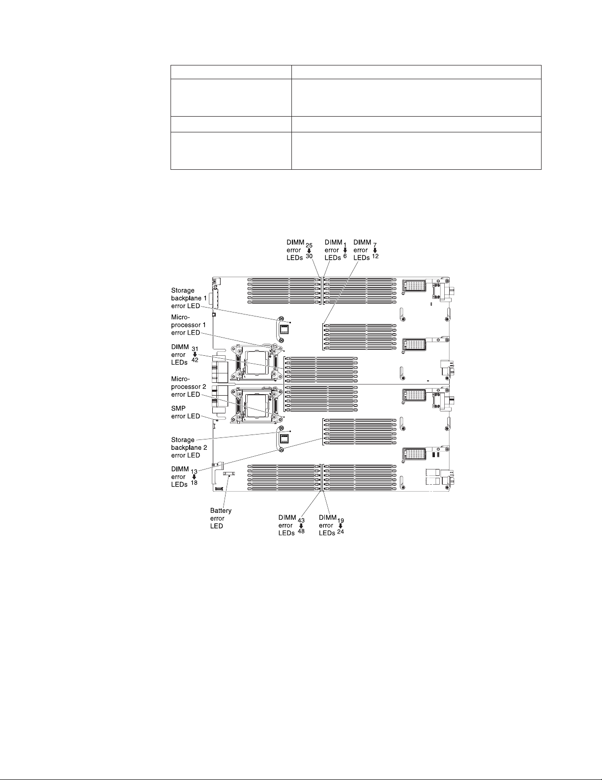
System-board LEDs
The following illustration shows the location of the LEDs on the system board.
pins 1 and 2 to indicate a physical presence to the IMM2
TPM chip.
jumper on pins 1 and 2 to force power permission from the
IMM2 to the real time management module (RTMM).
System-board switches
Use this information to locate the system-board switches.
The following illustration shows the location of the switch blocks on the system
board.
Chapter 1. Introduction 19
Page 32

On Off
8
7
65
4
3
21
On Off
8
7
65
4
3
21
SW8110
switch
SW8111
switch
The following table describes the functions of the switches.
Switch number Description Switch setting Definition
SW8110-1 Password override The default position is
off.
SW8110-2 UEFI TPM The default position is
off.
SW8110-3 Real time clock (RTC)
reset
The default position is
off.
Changing this switch
to the on position
overrides the
power-on password.
Changing this switch
to the on position
indicates a physical
presence to the TPM.
Changing this switch
to the on position
resets the RTC. A
momentary toggle is
all that is required. To
avoid excessive CMOS
battery drain, do not
leave this switch in the
on position.
20 Flex System x280 X6, x480 X6, and x880 X6 Compute Node Types 7903 and 4259: Installation and Service Guide
Page 33

Switch number Description Switch setting Definition
SW8110-4 Boot backup IMM2 The default position is
off.
When the switch is in
the default off
position, the compute
node will boot by
using the primary
IMM2 firmware. When
the switch is in the on
position, the compute
node will boot by
using a backup of the
IMM2 firmware.
SW8110-5 Boot backup UEFI The default position is
off.
Changing this switch
to the on position
forces the compute
node to boot from the
backup UEFI image.
SW8110-6 IMM force update The default position is
off.
Changing this switch
to the on position
bypasses the
operational firmware
image and performs a
IMM firmware update,
if the normal firmware
update procedure
results in an
inoperative IMM.
Note: Use this switch
only if the normal
firmware update
procedure fails and the
operational firmware
image is corrupted.
Use of this switch
disables normal
baseboard
management controller
operation.
SW8110-7 IMM SPI ROM Chip
Select
The default position is
off.
Changing this switch
to the on position
forces the compute
node to select system
SPI ROM0 or ROM1.
SW8110-8 Real time management
module (RTMM) flash
bypass
The default position is
off.
Changing this switch
to the on position
forces the compute
node to use RTMM
ROM instead of flash.
SW8111-1 Reset FPGA
Configuration Logic
The default position is
off.
Changing this switch
to the on position
forces the compute
node to reset the
FPGA configuration
logic.
Chapter 1. Introduction 21
Page 34

Switch number Description Switch setting Definition
SW8111-2 IMMv2 Reset The default position is
off.
SW8111-3 ME Flash descriptor
security override
SW8111-4 Boot Backup ME The default position is
SW8111-5,
SW8111-6
SW8111-7,
SW8111-8
Selecting dongle serial
port MUX (U9812)
Selecting dongle serial
port MUX (U9811)
The default position is
off.
off.
on, on
off, on
on, off
off, off
on, on
off, on
on, off
off, off
Changing this switch
to the on position
forces the compute
node to reset the IMM.
Changing this switch
to the on position
forces the compute
node to override
security in the flash
descriptor.
Changing this switch
to the on position
forces the compute
node to boot from the
backup ME.
LOM TX/RX
RTMM TX/RX
IMM TX/RX
SIO TX/RX
SAS TX/RX
FPGA TX/RX
IMM TX/RX
SIO RTS/CTS
Working with scalable partitions
This topic provides information about connecting multiple compute nodes together
to create scalable partitions.
A multi-node complex supports the following implementation modes:
v Single partition: The configuration functions as a single compute node that
contains up to eight microprocessors and 192 DIMMs. When the configuration is
implemented as a single-hardware partition, the lowest node bay ID in the
chassis is the primary node. The single partition uses the operating system of the
primary compute node.
The other nodes are the secondary nodes. The secondary nodes use the UEFI
settings defined for the primary node through the IMM. Each secondary
compute node retains its own UEFI settings for later use in stand-alone mode or
as a primary node.
Note: If you purchased a multi-node complex and you received each compute
node packaged individually, each compute node has a label on the top of the
bezel identifying the primary node and the secondary nodes as defined at the
factory during testing. Install the nodes in the chassis in the order indicated on
the label.
You can configure one, two, or four compute nodes into a single partition.
v Multiple partitions: The computes nodes are configured to form multiple
partitions within a multi-node complex.
– Two partitions each containing one compute node
– Two partitions each containing two compute nodes
– One partition containing four compute nodes
22 Flex System x280 X6, x480 X6, and x880 X6 Compute Node Types 7903 and 4259: Installation and Service Guide
Page 35

– One partition containing two compute nodes and two partitions each
containing one compute node
v Stand-alone mode: The compute nodes operate independently within a
multi-node complex. Each compute node uses its own UEFI settings.
To partition a multi-node complex, use the IMM2 Web interface (see “Partitioning a
multi-node complex” on page 25 for more information).
FlexNode partitioning
This topic provides information about FlexNode partitioning.
With FlexNode partitioning, you can toggle between a single partition or multiple
partitions without having to modify the physical setup of the compute nodes. To
toggle between partitions, use the IMM2 Web interface.
Single partition considerations
The following considerations apply to compute nodes in a multi-node complex that
operate as a single-hardware partition:
v The single partition uses the UEFI settings (set through the Setup utility) defined
for the primary compute node.
v If you update firmware using UpdateXpress System Packs (UXSP), when you
upgrade the firmware for the compute nodes operating as a single partition, you
only have to upgrade the primary compute node. The firmware on the
secondary compute nodes is automatically updated.
v The primary compute node has access to the hard disk drives and SSDs on the
secondary compute nodes.
v Use the UEFI multi-node drive sharing setting to combine the drives on the
primary compute node with the drives on the secondary compute nodes to form
a single RAID array. RAID arrays can be formed only using the drives in
individual compute nodes.
v The primary compute node has access to any I/O expansion adapters that are
installed in the secondary compute nodes. However, the I/O expansion adapters
in the secondary compute nodes cannot be used for a Serial Over LAN
connection.
v When you press the power-control button on any compute node in a single
partition (controlled by one operating system), all compute nodes in the single
partition will be turned on or turned off.
Chapter 1. Introduction 23
Page 36

24 Flex System x280 X6, x480 X6, and x880 X6 Compute Node Types 7903 and 4259: Installation and Service Guide
Page 37

Chapter 2. Configuring
Use this information to update the firmware and use the configuration utilities.
Partitioning a multi-node complex
Before you configure the compute nodes that are part of a multi-node complex,
you must partition the multi-node complex.
About this task
To partition a multi-node complex, complete the following steps.
Procedure
1. From the IMM2 Web interface, click Server Management > Scalable Complex.
Note: The Scalable Complex selection is only available when a compute node
that supports scalable partitions is installed in the chassis.
2. Select one or more unassigned compute nodes.
3. Click Create Partition.
What to do next
For more information, see Chapter 4, “Accessing the IMM2,” on page 49.
Updating firmware and device drivers
Lenovo periodically makes UEFI code, IMM2 firmware, diagnostic firmware
updates, and device driver updates available for the compute node. Provisioning is
the set of actions that you take to update the firmware and device drivers and
install the operating system. Several tools are available to help you update the
firmware and device drivers in the provisioning process.
Attention: Installing the wrong firmware or device-driver update might cause the
compute node to malfunction. Before you install a firmware or device-driver
update, read any readme and change history files that are provided with the
downloaded update. These files contain important information about the update
and the procedure for installing the update, including any special procedure for
updating from an early firmware or device-driver version to the latest version.
Notes:
1. If you update firmware using UpdateXpress System Packs (UXSP), when you
upgrade the firmware for the compute nodes operating as a single partition,
you only have to upgrade the primary compute node. The firmware on the
secondary compute nodes is automatically updated.
2. If you update firmware in a scalable partition using ToolsCenter Bootable
Media Creator, you only have to upgrade each primary node. The firmware on
the secondary compute nodes is automatically updated.
© Lenovo 2015. Portions © IBM Corp. 2014. 25
Page 38

3. If you are using a compute node that came with the Ethernet
LAN-on-motherboard (LOM) controller integrated on the system board, you
can find the device drivers at http://www.emulex.com/downloads/ibm/vfasoftware-kits.html.
4. Follow the instructions in the readme file that comes with the firmware update.
v Flex System Manager Update Manager
Flex System Manager Update Manager (if installed) acquires, installs, and
manages firmware and device driver updates and monitors your compute nodes
to ensure that they remain current. For more information about Flex System
Manager Update Manager, see http://pic.dhe.ibm.com/infocenter/flexsys/
information/topic/com.ibm.acc.8731.doc/updating_firmware_and_software.html.
v UpdateXpress System Packs
UpdateXpress System Packs (UXSP) contain an integration-tested bundle of
online, updateable firmware and device drivers for your compute node. The
ToolsCenter Bootable Media Creator uses UpdateXpress System Packs to update
the firmware and device drivers.
Typically, use UpdateXpress System Packs to update firmware and devices
drivers for a compute node that has previously been provisioned. For more
information about UpdateXpress System Packs, see http://www.ibm.com/
support/entry/portal/docdisplay?lndocid=SERV-XPRESS.
v ToolsCenter Bootable Media Creator
You can use ToolsCenter Bootable Media Creator to create bootable media that is
suitable for applying firmware updates and running preboot diagnostics. Using
ToolsCenter Bootable Media Creator, you can create a single bootable image on
supported media (such as CD, DVD, ISO image, USB flash drive, or set of PXE
files) that bundles multiple Flex System tools and updates from UpdateXpress
System Packs, which contain Windows and Linux
®
firmware updates.
Typically, use ToolsCenter Bootable Media Creator for the initial setup of a
compute node. For more information about the Bootable Media Creator, see
http://www.ibm.com/support/entry/portal/docdisplay?lndocid=TOOL-BOMC.
To provision a compute node with updated firmware and device drivers by
using ToolsCenter Bootable Media Creator and the Flex System Manager
management software, complete the following steps:
1. Download ToolsCenter Bootable Media Creator to a computer that is
connected over the management network to the Flex System Manager
management software that is managing the compute node.
2. Create the bootable media of firmware and device driver updates.
3. Connect to the Flex System Manager management software that is managing
the Flex System chassis in which the compute node is installed.
4. From Flex System Manager Chassis Manager, select the compute node. In the
Actions column, select Remote Control.
Note: The user ID that you use to log in to Flex System Manager
management software must have sufficient user permissions to manage the
compute node.
5. From the Remote Control session, mount the bootable media (using Remote
Media).
6. Start the compute node to boot the media and install the updates.
v Integrated management module II (IMM2)
26 Flex System x280 X6, x480 X6, and x880 X6 Compute Node Types 7903 and 4259: Installation and Service Guide
Page 39

You can use IMM2 to update some types of compute node firmware. For more
information about the IMM2, see http://www.ibm.com/support/entry/portal/
docdisplay?lndocid=MIGR-5086346.
Important: To avoid problems and to maintain system performance, always make
sure that the UEFI code, IMM2 firmware, and diagnostic firmware levels are
consistent in all compute nodes in the Flex System chassis.
For additional information about updating firmware and device drivers, see UEFI
Compliant Firmware on System x
Quick start guides, and the Firmware Update Guides at http://www.ibm.com/
support/entry/portal/docdisplay?lndocid=MIGR-5091991 (an user ID might be
required to access this content).
Recovering a UEFI image
Use this information to recover a UEFI image.
About this task
The compute node has an advanced recovery feature that automatically switches to
a backup UEFI page if the UEFI code in the compute node has become damaged,
such as from a power failure during an update. The flash memory of the compute
node consists of a primary page and a backup page. If the UEFI code in the
primary page is damaged, the integrated management module detects the error
and automatically switches to the backup page to start the compute node. If this
happens, a POST message Booted from backup UEFI image is displayed, the check
log LED is lit, and an automatic BIOS recovery (ABR) condition occurs. The
backup page version might not be the same as the primary page version.
You can then recover or restore the original primary page UEFI.
Note: Changes are made periodically to the website. The actual procedure might
vary slightly from what is described in this document.
®
and BladeCenter®Servers. and the Flex System
Procedure
To recover the UEFI code and restore the compute node operation to the primary
page, complete the following steps:
1. Update the UEFI code (see “Updating firmware and device drivers” on page
25).
2. Restart the compute node.
3. At the firmware splash screen, press F3 when prompted to restore to the
primary bank. The compute node boots from the primary bank.
Note: The prompt to press F3 displays only if the compute node boots from
the backup page due to an ABR condition.
What to do next
If the attempt to flash the primary page results in the compute node not booting
and the check log LED is not lit, you can manually restore the UEFI code. To
manually restore the UEFI code, complete the following steps.
Chapter 2. Configuring 27
Page 40

Note: If the check log LED is lit, the compute node is booting from the backup
image and moving the switch to backup changes nothing.
1. Before you begin, read “Safety” on page v and “Installation guidelines” on
page 699.
2. Turn off the compute node (see “Turning off the compute node” on page 16).
3. Remove the compute node from the Flex System chassis (see “Removing a
compute node from a chassis” on page 701).
4. Remove the cover (see “Removing the compute node cover” on page 715).
5. Locate the boot backup UEFI switch on the switch block and move the switch
to the On position (see “System-board switches” on page 19).
6. Replace the cover and reinstall the compute node in the Flex System chassis
(see “Installing the compute node cover” on page 716 and “Installing a
compute node in a chassis” on page 702).
7. Update the UEFI code (see “Updating firmware and device drivers” on page
25).
8. Turn off the compute node and remove it from the Flex System chassis (see
“Turning off the compute node” on page 16 and “Removing a compute node
from a chassis” on page 701).
9. Remove the cover of the compute node (see “Removing the compute node
cover” on page 715).
10. Locate the boot backup UEFI switch on the switch block and move the switch
to the Off position (see “System-board switches” on page 19).
11. Replace the cover and reinstall the compute node in the Flex System chassis
(see “Installing the compute node cover” on page 716 and “Installing a
compute node in a chassis” on page 702).
12. Restart the compute node (see “Turning on the compute node” on page 15).
Important: If you are unable to manually restore the UEFI code after several
attempts, replace the system-board assembly (see “Removing the system-board
components for base-assembly replacement” on page 767 and “Installing the
system-board components for base-assembly replacement” on page 769).
Configuring the compute node
Use this information to configure the compute node.
Procedure
To perform a typical initial configuration, complete the following steps:
Note: To configure a compute node, you configure the IP address of the IMM
through the CMM Web interface. For more information, see the "Flex System
Chassis Management Module: User's Guide" at http://pic.dhe.ibm.com/
infocenter/flexsys/information/topic/com.ibm.acc.cmm.doc/
cmm_user_guide.html.
1. Configure the Unified Extensible Firmware Interface (UEFI) firmware for the
compute node by using the Setup utility (see “Using the Setup utility” on page
29 or the Advanced Setup Utility (ASU) (see http://www.ibm.com/support/
entry/portal/docdisplay?lndocid=TOOL-ASU).
For more information about firmware configuration options, see
http://www.ibm.com/support/entry/portal/docdisplay?lndocid=MIGR-
5083207.
28 Flex System x280 X6, x480 X6, and x880 X6 Compute Node Types 7903 and 4259: Installation and Service Guide
Page 41

2. Set the boot protocol by using the Setup utility (see “Setting the boot protocol
to boot from legacy devices using the Setup utility” on page 35).
You can temporarily redefine the boot order by using the Boot Selection menu
program (see “Using the Boot Selection Menu program” on page 36).
3. Configure the RAID array.
You can install up to two hard disk drives in the compute node and implement
RAID level-0 (striping) or RAID level-1 (mirror) arrays in operating systems
that are listed on the ServerProven list at http://www.ibm.com/systems/info/
x86servers/serverproven/compat/us. For the compute node, you must
configure the RAID by using the LSI Configuration Utility program (see “Using
the LSI Logic Configuration Utility” on page 40).
If an optional RAID expansion adapter is installed, you can use it to control all
the hard disk drives that are installed in the compute node. See the
documentation that comes with the expansion adapter for information about
how to configure the RAID array.
Important: You must create the RAID array before you install the operating
system on the compute node.
4. Configure the integrated management module II (IMM2) using either the Setup
utility or the Advanced Settings Utility (ASU).
5. Update the compute node firmware (see “Updating firmware and device
drivers” on page 25).
Notes:
a. If you use Flex System Manager Update Manager to update the firmware,
you can optionally start the operating-system installation while the
firmware updates are installed. It is normal operation for the initial
firmware updates to take an unusual length of time.
b. If the Chassis Management Module (CMM) and the compute nodes are set
up to use DHCP and the CMM loses connectivity to the network, the CMM
attempts to acquire a new IP address when network connectivity is restored.
The compute nodes will not attempt to acquire an IP address again; they
will continue to use their original IP addresses. Therefore, if you experience
network problems on compute nodes after connectivity between the CMM
and the network is restored, you might have to reset the
system-management processor in each of the compute nodes in the chassis
(including the management node).
What to do next
After you configure the compute node, you can install the operating system and
update device drivers (see Chapter 3, “Installing the operating system,” on page 45
for more information).
Using the Setup utility
Use these instructions to start the Setup utility.
Procedure
You can access the Setup utility remotely through the CMM web interface. From
the CMM web interface, select Launch Compute Node Console. For more
information, see the "Flex System Chassis Management Module: User's Guide" at
Chapter 2. Configuring 29
Page 42

http://pic.dhe.ibm.com/infocenter/flexsys/information/topic/
com.ibm.acc.cmm.doc/cmm_user_guide.html. All fields and options are described
in the CMM web interface online help.
Note: The integrated management module II (IMM2) must have a valid IP
address.
To start the Setup utility locally, complete the following steps:
1. If the compute node is turned on, turn off the compute node (see “Turning off
the compute node” on page 16.
Attention: Use only the console breakout cable that comes with the compute
node. Attempting to connect other console breakout cable types might damage
the console breakout cable and the compute node.
2. If necessary, connect a keyboard, monitor, and mouse to the console breakout
cable and connect the console breakout cable to the compute node).
3. Turn on the compute node (see “Turning on the compute node” on page 15).
4. When the prompt Press <F1> Setup is displayed, press F1.
v If you have set an administrator password, you must type the administrator
password to access the full Setup utility menu. If you do not type the
administrator password, a limited Setup utility menu is available.
v If you have not set an administrator password, the full Setup utility menu is
available to all users.
5. The Setup utility is organized in a menu structure which enables you to view
and change the settings. The keyboard characters used to navigate the Setup
utility screen and change settings are shown at the bottom of the Setup utility
screens.
Results
The following menu items are on the Setup utility main menu. Depending on the
version of the Unified Extensible Firmware Interface (UEFI), some menu items
might differ slightly from these descriptions.
v System Information
Select this choice to view information about the compute node. When you make
changes through other choices in the Setup utility, some of those changes are
reflected in the system information; you cannot change settings directly in the
system information. This choice is on the full Setup utility menu only.
– System Summary
Select this choice to view configuration information, including the ID, speed,
and cache size of the microprocessors, machine type and model of the
compute node, the serial number, the system Universally Unique Identifier
(UID), and the amount of installed memory.
– Product Data
Select this choice to view the system-board identifier, the revision level or
issue date of the firmware, the integrated management module II and
diagnostics code, and the version and date.
This choice is on the full UEFI Setup utility menu only.
v System Settings
Select this choice to view or change the compute node component settings.
– Adapters and UEFI Drivers
30 Flex System x280 X6, x480 X6, and x880 X6 Compute Node Types 7903 and 4259: Installation and Service Guide
Page 43

Select this choice to view information about the adapters and UEFI device
drivers in the compute node.
Note: Before you configure a UEFI-compatible device, update the firmware
for your compute node. See “Updating firmware and device drivers” on page
25 for information about how to update the firmware for your compute node.
To configure a UEFI-compatible expansion adapter, complete the following
steps:
1. Select Please press ENTER to compile the list of drivers and press Enter.
2. Select the device driver that you want to configure, and press Enter.
3. When you have finished changing settings, press Esc to exit from the
program; select Save to save the settings that you have changed.
– Devices and I/O Ports
Select this choice to view or change assignments for devices and
input/output (I/O) ports. You can configure the remote console redirection
and enable or disable the integrated Ethernet controller. If you disable a
device, it cannot be configured, and the operating system cannot detect it
(disabling a device is equivalent to disconnecting the device).
You can also choose to enable or disable adapter option ROM support.
Disabling support can potentially improve the time it takes the compute node
to start.
– Driver Health
Select this choice to view the health status of the controllers as reported by
the device drivers. You can select to perform a repair action on a device
driver.
– Integrated Management Module
Select this choice to view or change the settings for the integrated
management module II (IMM2).
- Power Restore Policy
Select this choice to determine the state to which the compute node will be
restored after a power outage.
- Commands on USB Interface
Select this choice to specify whether the Ethernet over USB interface is
enabled or disabled.
Note: This option is primarily for older operating systems that have
problems with USB communications device class (CDC) Ethernet interfaces.
Disabling this option will cause the following issues:
v Online update packages will not work.
v Updates that use Bootable Media Creator (BoMC) will not work because
BoMC uses the LAN over USB interface.
v You must install the IPMI device driver to use the Advanced Settings
Utility (ASU) to change the IMM2 or UEFI configuration.
v You cannot set the IMM2 OS loader watchdog.
- Network Configuration
Select this choice to view the system-management network interface port,
IMM2 MAC address, current IMM2 IP address, and host name; define the
static IMM2 IP address, subnet mask, and gateway address; specify
whether to use the static IP address or have DHCP assign the IMM2 IP
address; save the network changes; and reset the IMM2.
Chapter 2. Configuring 31
Page 44

- Reset IMM to Defaults
Select this choice to restore the IMM2 to the manufacturing default settings.
The IMM2 controller restarts after you restore the settings.
- Reset IMM
Select this choice to restart the IMM2 controller.
– Legacy Support
Select this choice to view or set legacy support.
- Force Legacy Video on Boot
Select this choice to enable or disable force INT video support, if the
operating system does not support UEFI video output standards. The
default is Enable.
- Rehook INT
Select this choice to enable or disable devices from taking control of the
boot process. The default is Disable.
- Legacy Thunk Support
Select this choice to enable or disable UEFI to interact with PCI mass
storage devices that are non-UEFI compliant. The default is Enable.
- Infinite Boot Retry
Select this choice to enable or disable UEFI to infinitely retry the legacy
boot order.
- BBS Boot
Select this choice to enable or disable legacy boot in accordance with the
BIOS Boot Specification (BBS).
- Non-Planar PXE
Select this choice to enable or disable non-system-board PXE for legacy
mode.
– Memory
Select this choice to view or change the memory settings.
If a memory error is detected during POST or memory configuration, the
compute node automatically disables the failing pair of memory connectors
and continues operating with reduced memory. After the problem is
corrected, you must manually enable the memory connectors. Select System
Memory Details and use the arrow keys to highlight the pair of memory
connectors that you want to enable; then, set the connectors to Enable.
– Network
Select this choice to view or configure the network device options, such as
iSCSI, PXE, and network devices.
– Operating Modes
Select this choice to determine operational settings, such as operating mode
(minimal power, efficiency, or maximum performance) and memory speed.
– Power
Select this choice to view or change the power scheme settings.
– Processors
Select this choice to view or change the microprocessor settings.
– Recovery and RAS
Select this choice to view or change the system recovery and advanced RAS
parameters.
- Advanced RAS
32 Flex System x280 X6, x480 X6, and x880 X6 Compute Node Types 7903 and 4259: Installation and Service Guide
Page 45

Select this choice to enable advanced RAS options.
- Backup Bank Management
Select this choice to configure the backup bank management settings.
- Disk GPT Recovery
Select this choice to enable or disable GUID partition table (GPT) drive
recovery.
- POST Attempts
Select this choice to define the number of times to attempt POST before
invoking the recovery procedures.
- System Recovery
Select this choice to configure the recovery settings.
v POST Watchdog Timer
Select this choice to view or enable the POST watchdog timer.
v POST Watchdog Timer Value
Select this choice to view or set the POST loader watchdog timer value.
v Reboot System on NMI
Select this choice to enable or disable restarting the system whenever a
nonmaskable interrupt (NMI) occurs. The default is Disable.
v Halt On Severe Error
Select this choice to enable or disable the system starting the operating
system whenever a severe error is detected during POST. A setting of
Enable prevents the system from starting the operating system when a
severe POST error occurs, instead starting the POST Event Viewer. The
default is Disable.
– Security
Select this option to view or configure the Secure Boot feature and Trusted
Platform Module (TPM 1.2).
- Secure Boot Configuration
Select this choice to enable and disable the Secure Boot feature or set the
Secure Boot mode.
- Trusted Platform Module (TPM 1.2)
Select this choice to view or configure the TPM setup options.
– Storage
Select this choice to view and manage RAID controller configurations.
v Date and Time
Select this choice to set the date and time for the compute node. The date is set
in month/day/year format. The time is set in 24-hour format (hour:minute:second).
This choice is on the full UEFI Setup utility menu only.
v Start Options
Select this choice to view or change the startup sequence. The startup sequence
specifies the order in which the compute node checks devices to find a boot
record. The compute node starts from the first boot record that it finds. If the
compute node has Wake on LAN hardware and software and the operating
system supports Wake on LAN functions, you can specify a startup sequence for
the Wake on LAN functions. For example, you can define a startup sequence
that checks for a disc in the CD or DVD drive, then checks the hard disk drive,
and then checks a network adapter.
This choice is on the full UEFI Setup utility menu only.
Chapter 2. Configuring 33
Page 46

v Boot Manager
Select this choice to view, add, delete, or change the device boot priority, boot
from a file, select a one-time boot, or reset the boot order to the default setting.
Select Boot Modes to view or change the boot settings. You can set the boot
mode and choose UEFI operating-system support only, or legacy
operating-system support only.
Note: If you select the legacy-only boot mode (which makes boot time much
faster), you will not be able to activate any Features on Demand (FoD) keys.
v System Event Logs
Select this choice to access the System Event Manager, where you can view the
POST event log and the system-event log.
The POST event log contains the three most recent error codes and messages
that were generated during POST.
The system-event log contains POST and system management interrupt (SMI)
events and all events that are generated by the baseboard management
controller that is embedded in the integrated management module II.
Important: If the system-error LED on the front of the compute node is lit but
there are no other error indications, clear the system-event log. Also, after you
complete a repair or correct an error, clear the system-event log to turn off the
system-error LED on the front of the compute node.
– POST Event Viewer
Select this choice to enter the POST event viewer to view the UEFI diagnostic
codes.
– System Event Log
Select this choice to view the system-event log.
– Clear System Event Log
Select this choice to clear the system-event log.
v User Security
Select this choice to set, change, or clear passwords.
You can set, change, and delete a power-on password and an administrator
password through this selection.
– If you set a power-on password, you must type the power-on password to
complete the system startup and to have access to the Setup utility main
menu.
– If you set an administrator password, you must type the administrator
password to have access to the full Setup utility main menu. If you do not
type the administrator password when one is set, a limited Setup utility menu
is available.
You can use any combination of up to from 6 to 20 characters (A - Z,a-z,and0
- 9) for passwords. Keep a record of your password in a secure place.
If you forget the power-on password, you can regain access to the compute node
by using the power-on password override switch (see “System-board switches”
on page 19).
Attention: If you set an administrator password and then forget it, there is no
way to change, override, or remove it. You must replace the system board.
You can also regain access to the compute node by removing the CMOS battery
and then reinstalling it (see “Removing the CMOS battery” on page 712 and
“Installing the CMOS battery” on page 713).
34 Flex System x280 X6, x480 X6, and x880 X6 Compute Node Types 7903 and 4259: Installation and Service Guide
Page 47

Important: Removing the CMOS battery clears the settings in CMOS memory.
v Save Settings
Select this choice to save the changes that you have made in the settings.
v Restore Settings
Select this choice to cancel the changes that you have made in the settings and
restore the previous settings.
v Load Default Settings
Select this choice to cancel the changes that you have made in the settings and
restore the manufacturing settings.
v Exit Setup
Select this choice to exit from the Setup utility. If you have not saved the
changes that you have made in the settings, you are asked whether you want to
save the changes or exit without saving them.
Nx boot failure
Configuration changes, such as added devices or adapter firmware updates, and
firmware or application code problems can cause a compute node to fail the
power-on self-test (POST).
If a compute node fails POST, it responds in either of the following ways:
v The compute node restarts automatically and attempts POST again.
v The compute node hangs and you must manually restart the compute node for
the compute node to attempt POST again.
After a specified number of consecutive attempts (automatic or manual), the Nx
boot failure feature causes the compute node to revert to the default UEFI
configuration and start the Setup utility, so that you can make the necessary
corrections to the configuration and restart the compute node. If the compute node
is unable to successfully complete POST with the default configuration, there
might be a problem with the system board.
To specify the number of consecutive restart attempts that will trigger the Nx boot
failure feature in the Setup utility, click System Settings > Recovery > Post
Attempts. The available options are 3, 6, 9 and Disable.
Setting the boot protocol to boot from legacy devices using the Setup utility
This option disables UEFI ROMs from loading. The compute node will boot legacy
mode only.Use the Setup utility to configure the boot protocol to boot from a
non-UEFI legacy network device for all PXE boot attempts.
To use the Setup utility to configure the boot protocol to boot from a non-UEFI
legacy network device for all PXE boot attempts, complete the following steps:
Attention: Use only the console breakout cable that comes with the compute node.
Attempting to connect other console breakout cable types might damage the
console breakout cable and the compute node.
1. Connect a keyboard, monitor, and mouse to the console breakout cable and
connect the console breakout cable to the compute node.
2. Turn on the compute node (see “Turning on the compute node” on page 15).
Chapter 2. Configuring 35
Page 48

3. When the prompt Press <F1> Setup is displayed, press F1. If you have set an
administrator password, you must type the administrator password to access
the full Setup utility menu. If you do not type the administrator password, a
limited Setup utility menu is available.
4. From the Setup utility main menu, select Boot Manager.
5. Select Boot Modes; then select Legacy Only.
6. Press Esc twice to return to the Boot Manager menu.
7. Select Change Boot Order and move the non-UEFI legacy network device to
the top of the boot order.
8. Press Esc twice to return to the Setup utility main menu.
9. Select Save Settings and then select Exit Setup.
To use the Setup utility to configure the boot protocol to boot from a non-UEFI
legacy network device, complete the following steps:
Attention: Use only the console breakout cable that comes with the compute node.
Attempting to connect other console breakout cable types might damage the
console breakout cable and the compute node.
1. Connect a keyboard, monitor, and mouse to the console breakout cable and
connect the console breakout cable to the compute node.
2. Turn on the compute node (see “Turning on the compute node” on page 15).
3. When the prompt Press <F1> Setup is displayed, press F1. If you have set an
administrator password, you must type the administrator password to access
the full Setup utility menu. If you do not type the administrator password, a
limited Setup utility menu is available.
4. From the Setup utility main menu, select Boot Manager.
5. Select Add Boot Option; then, select Generic Boot Option.
6. Select Legacy Only.
7. Press Esc three times to return to the Setup utility main menu.
8. Select Save Settings and then, select Exit Setup.
Using the Boot Selection Menu program
The Boot Selection Menu program is a built-in, menu-driven configuration utility
program that you can use to temporarily redefine the first startup device without
changing settings in the Setup utility.
Procedure
To use the Boot Selection Menu program, complete the following steps:
1. Connect a keyboard, monitor, and mouse to the console breakout cable, and
connect the console breakout cable to the compute node.
Attention: Use only the console breakout cable that comes with the compute
node. Attempting to connect other console breakout cable types might damage
the console breakout cable and the compute node.
2. Turn on the compute node (see “Turning on the compute node” on page 15).
3. Press F12 (Select Boot Device). If a bootable USB mass storage device is
installed, a submenu item (USB Key/Disk) is displayed.
4. Use the Up Arrow and Down Arrow keys to select an item from the Boot
Selection Menu and press Enter.
36 Flex System x280 X6, x480 X6, and x880 X6 Compute Node Types 7903 and 4259: Installation and Service Guide
Page 49

Results
The next time the compute node starts, it returns to the startup sequence that is set
in the Setup utility.
Updating the Universally Unique Identifier and DMI/SMBIOS data
After the system board is replaced, you must update the Universally Unique
Identifier (UUID) and DMI/SMBIOS data in the integrated management module II
(IMM2) on the new system board.
You can use the Advanced Settings Utility (ASU) and any of the following access
methods:
v Locally (in-band)
– Through the Keyboard Controller Style (KCS) interface
– Through the LAN over USB interface
v Remotely over a LAN
You can use the ASU under any supported operating system, or you can use the
Bootable Media Creator or a Windows- or Linux-based toolkit to create bootable
media that contains the ASU. For information about the ASU and instructions for
downloading and unpacking the ASU code, see http://www.ibm.com/support/
entry/portal/docdisplay?lndocid=TOOL-ASU and the Advanced Settings Utility
User's Guide.
The following sections provide instructions for updating the UUID and
DMI/SMBIOS data, using the different methods for accessing the IMM2. The
following conventions apply to the command syntax:
v Variables are shown in italics.
v Optional parameters are enclosed in brackets ([ ]). Do not type the brackets in
the commands. If you omit an optional parameter, the default is used.
v Although the command syntax is shown in mixed case, the commands are not
case sensitive.
Locally: Keyboard Controller Style (KCS)
This access method uses the IPMI/KCS interface. The IPMI driver must be
installed; with some operating systems, the IPMI driver is installed by default. The
ASU provides the corresponding mapping layer.
Procedure
To update the UUID, in the ASU command-line interface, enter the following
command:
asu set SYSTEM_PROD_DATA.SysInfoUUID uuid
where uuid is the user-assigned hexadecimal value, up to 16 bytes, that identifies
the compute node.
To update the DMI/SMBIOS data, complete the following steps:
1. In the ASU command-line interface, enter the following command:
asu set SYSTEM_PROD_DATA.SysInfoProdName xxxxyyy
where:
xxxx is the 4-digit machine type of the compute node.
Chapter 2. Configuring 37
Page 50

yyy is the 3-digit model number of the compute node.
2. Enter the following command:
asu set SYSTEM_PROD_DATA.SysInfoSerialNum zzzzzzz
where zzzzzzz is the 7-character serial number of the compute node.
3. Enter the following command:
asu set SYSTEM_PROD_DATA.SysEncloseAssetTag
aaaaaaaaaaaaaaaaaaaaaaaaaaaaaaaaa
where aaaaaaaaaaaaaaaaaaaaaaaaaaaaaaaaa is the 33-character asset tag number of
the compute node.
Locally: LAN over USB
If you omit any optional parameter, the default value is used. If one or more
default values are used and the ASU cannot access the IMM2 by using the LAN
over USB access method, the ASU automatically uses the KCS access method.
Procedure
To update the UUID, in the ASU command-line interface, enter the following
command:
asu set SYSTEM_PROD_DATA.SysInfoUUID uuid
[--user userid][--password password]
where:
uuid is the user-assigned hexadecimal value, up to 16 bytes, that identifies the
compute node.
userid is the IMM2 account name (1 of 12 accounts). The default is USERID.
password
is the IMM2 account password (1 of 12 accounts). The default is
PASSW0RD (with a zero, not the letter O).
To update the DMI/SMBIOS data, complete the following steps:
1. In the ASU command-line interface, enter the following command:
asu set SYSTEM_PROD_DATA.SysInfoProdName xxxxyyy [--host ipaddress]
[--user userid][--password password]
where:
xxxx is the 4-digit machine type of the compute node.
yyy is the 3-digit model number of the compute node.
ipaddress
is the internal LAN/USB IP address of the IMM2. The default is
169.254.95.118.
userid is the IMM2 account name (1 of 12 accounts). The default is USERID.
password
is the IMM2 account password (1 of 12 accounts). The default is
PASSW0RD (with a zero, not the letter O).
2. Enter the following command:
38 Flex System x280 X6, x480 X6, and x880 X6 Compute Node Types 7903 and 4259: Installation and Service Guide
Page 51

asu set SYSTEM_PROD_DATA.SysInfoSerialNum zzzzzzz [--host ipaddress]
[--user userid][--password password]
where zzzzzzz is the 7-character serial number of the compute node.
3. Enter the following command:
asu set SYSTEM_PROD_DATA.SysEncloseAssetTag
aaaaaaaaaaaaaaaaaaaaaaaaaaaaaaaaa [--host ipaddress]
[--user userid][--password password]
where aaaaaaaaaaaaaaaaaaaaaaaaaaaaaaaaa is the 33-character asset tag number of
the compute node.
Remotely over a LAN
If you omit any optional parameter, the default value is used.
Procedure
To update the UUID, in the ASU command-line interface, enter the following
command:
asu set SYSTEM_PROD_DATA.SysInfoUUID uuid --host ipaddress
[--user userid][--password password]
where:
uuid is the user-assigned hexadecimal value, up to 16 bytes, that identifies the
compute node.
ipaddress
is the external LAN IP address of the IMM2.
userid is the IMM2 account name (1 of 12 accounts). The default is USERID.
password
is the IMM2 account password (1 of 12 accounts). The default is
PASSW0RD (with a zero, not the letter O).
To update the DMI/SMBIOS data, complete the following steps:
1. In the ASU command-line interface, enter the following command:
asu set SYSTEM_PROD_DATA.SysInfoProdName xxxxyyy --host ipaddress
[--user userid][--password password]
where:
xxxx is the 4-digit machine type of the compute node.
yyy is the 3-digit model number of the compute node.
ipaddress
is the external LAN IP address of the IMM2.
userid is the IMM2 account name (1 of 12 accounts). The default is USERID.
password
is the IMM2 account password (1 or 12 accounts). The default is
PASSW0RD (with a zero, not the letter O).
2. Enter the following command:
asu set SYSTEM_PROD_DATA.SysInfoSerialNum zzzzzzz --host ipaddress
[--user userid][--password password]
Chapter 2. Configuring 39
Page 52

where zzzzzzz is the 7-character serial number of the compute node.
3. Enter the following command:
asu set SYSTEM_PROD_DATA.SysEncloseAssetTag
aaaaaaaaaaaaaaaaaaaaaaaaaaaaaaaaa --host ipaddress
[--user userid][--password password]
where aaaaaaaaaaaaaaaaaaaaaaaaaaaaaaaaa is the 33-character asset tag number of
the compute node.
Enabling Features on Demand RAID software
This topic provides information about enabling Features on Demand RAID
software.
Integrated into the IMM2 is a Features on Demand RAID software upgrade key
that you can activate for enhanced RAID support. For more information and
instructions for activating the Features On Demand RAID software key, see the
Features on Demand User’s Guide at http://www.ibm.com/support/entry/portal/
docdisplay?lndocid=MIGR-5089568. For more information about Features on
Demand, go to http://www.ibm.com/systems/x/fod/.
Configuring a RAID array
Use this information to configure a RAID array.
About this task
Configuring a RAID array applies only to a compute node in which two or more
hard disk drives are installed.
Note: When you configure a RAID array, the hard disk drives must use the same
type of interface. For example, a RAID array can be configured with two SAS hard
disk drives or two SATA hard disk drives.
You can use two hard disk drives in the compute node to implement and manage
RAID level-0 (striping) or RAID level-1 (mirror) arrays in operating systems that
are listed on the ServerProven list at http://www.ibm.com/systems/info/
x86servers/serverproven/compat/us. For the compute node, you must configure
the RAID by using the LSI Configuration Utility program.
If an optional RAID expansion adapter is installed, you can use it to control all of
the hard disk drives that are installed in the compute node. See the documentation
that comes with the expansion adapter for information about how to configure the
RAID array.
Important: You must create the RAID array before you install the operating system
on the compute node.
You can use the LSI Logic Configuration Utility program to configure the hard disk
drives and the SAS controller. To start the LSI Logic Configuration Utility, see
“Using the LSI Logic Configuration Utility.”
Using the LSI Logic Configuration Utility
Use these instructions to start the LSI Logic Configuration Utility.
40 Flex System x280 X6, x480 X6, and x880 X6 Compute Node Types 7903 and 4259: Installation and Service Guide
Page 53

About this task
You can use the LSI Logic Configuration Utility to perform the following tasks:
v Set the device boot order
v Add or remove devices from the boot list
v Manage the RAID configuration
Note: The hard disk drive in the RAID configuration must use the same type of
interface and must have identical capacity and speed.
Procedure
To start the LSI Logic Configuration Utility program, complete the following steps:
1. Connect a keyboard, monitor, and mouse to the console breakout cable and
connect the console breakout cable to the compute node.
Attention: Use only the console breakout cable that comes with the compute
node. Attempting to connect other console breakout cable types might damage
the console breakout cable and the compute node.
2. Turn on the compute node (see “Turning on the compute node” on page 15).
3. When the prompt Press <F1> Setup is displayed, press F1. If you have set an
administrator password, you must type the administrator password to access
the full Setup utility menu. If you do not type the administrator password, a
limited Setup utility menu is available.
4. From the Setup utility main menu, select System Settings; then select Storage.
5. Use the arrow keys to select the controller from the list of adapters; then, press
Enter.
6. Follow the instructions on the screen to change the settings of the selected
items; then, press Enter. If you select SAS Topology or Advanced Adapter
Properties, additional screens are displayed.
Features on Demand
This topic provides information about Features on Demand.
Features on Demand provides optional software that is available for the compute
node and other Flex System resources. Features on Demand provides a convenient
way for you to activate optional software through the optional Flex System
Manager management software (see http://pic.dhe.ibm.com/infocenter/flexsys/
information/topic/com.ibm.acc.8731.doc/features_on_demand.html), the IMM2
interface (see http://www.ibm.com/support/entry/portal/
docdisplay?lndocid=MIGR-5086346), or the CMM web interface (see "Flex System
Chassis Management Module: User’s Guide" at http://pic.dhe.ibm.com/
infocenter/flexsys/information/topic/com.ibm.acc.cmm.doc/
cmm_user_guide.html). Any Features on Demand software that you ordered with
your compute node is preactivated and does not require manual activation.
Note: If the optional Flex System Manager management software is installed,
Features on Demand should be activated using the Flex System Manager
management software so that theses features are properly catalogued.
If you did not order Features on Demand software when you ordered the compute
node, you can purchase Features on Demand as you would any other optional
Chapter 2. Configuring 41
Page 54

software or hardware. Instructions for obtaining an activation key are provided
with your purchase of a Features on Demand authorization code.
For information about Features on Demand, see http://www.ibm.com/systems/x/
fod/.
Important:
1. If the compute node is configured in the Setup utility to boot in legacy mode,
you must leave UEFI option ROM initialization enabled for devices for which
Features on Demand feature keys are installed.
2. After you install an activation key for the first time, you might have to restart
the compute node for the Feature on Demand to become active. See the
documentation that comes with the software for specific activation instructions.
3. Make sure that the UEFI code, IMM2 firmware, and all other firmware in the
compute node is at the level that supports the Feature on Demand software.
Setting up the LAN-on-motherboard (LOM) feature
This topic provides information about setting up the LAN-on-motherboard (LOM)
feature.
Some models of the Flex System x280 X6, x480 X6, and x880 X6 Compute Node
Types 7903 and 4259 have one Ethernet LAN-on-motherboard (LOM) controller
integrated on the system board. The LOM provides the following features:
v Two operational mode choices:
– One-port physical NIC mode (pNIC), multichannel disabled, which is the
default.
– Virtual NIC mode (vNIC), multichannel enabled. vNIC mode enables up to 4
virtual NIC interfaces per 10 Gb physical port (8 total for the LOM).
For more information about how LOM ports are mapped to switch modules in
the chassis, see http://pic.dhe.ibm.com/infocenter/flexsys/information/topic/
com.ibm.acc.8721.doc/configuring_io_modules.html.
v Two options for vNIC linking:
– VNIC1, Virtual Fabric mode.
– VNIC2, Switch Independent mode.
You can select these options using the Setup utility (F1).
v Link auto negotiation 10 Gb/1 Gb full duplex.
v Bus-mastering support.
v Direct memory access (DMA) support.
v Interoperability with existing FC SAN infrastructures, such as switches, arrays,
SRM tools (including Emulex utilities), SAN practices, and other infrastructures.
v Unified Ethernet-to-FC SAN connectivity provided by an FCoE switch.
v 10 Gb MAC features such as MSI-X support, jumbo frames (8 KB) support,
VLAN tagging (802.1Q, PER priority pause/priority flow control), and advanced
packet filtering.
v NIC failover support.
v Support for IBM Fabric Manager (IFM).
v Preboot Execution Environment, UEFI, and Legacy PXE.
v Wake on LAN (WOL).
v SRIOV support.
42 Flex System x280 X6, x480 X6, and x880 X6 Compute Node Types 7903 and 4259: Installation and Service Guide
Page 55

v ISCSI or FCoE capabilities, which can be enabled through Features on Demand.
When enabled, the ISCSI or FCoE operations are supported on the second vNIC
of the physical port.
Separate NIC, ISCSI, and FCoE drivers are provided to support all configurations.
To obtain the device drivers, go to http://www.emulex.com/downloads/ibm/vfasoftware-kits.html.
No host operating system changes are required for you to use the LOM features.
NIC and HBA functionality (including device management, utilities, and other
functions) are transparent to the host operating system.
For more information about using the LOM feature, go to http://
www.emulex.com/support.html.
Chapter 2. Configuring 43
Page 56

44 Flex System x280 X6, x480 X6, and x880 X6 Compute Node Types 7903 and 4259: Installation and Service Guide
Page 57

Chapter 3. Installing the operating system
Use these instructions to install the operating system on the compute node.
To determine which operating systems are supported, see the following site:
http://www.ibm.com/systems/info/x86servers/serverproven/compat/us/nos/
flexmatrix.shtml
Provisioning is the set of actions that you take to install the operating system. To
install the operating system on a compute node, you can use any of the following
methods:
v LenovoServerGuide Setup and Installation CD
Use the ServerGuide Setup and Installation CD to install a supported Microsoft
Windows operating system only. To provision a compute node with an operating
system by using the ServerGuide Setup and Installation CD, complete the following
steps.
1. Download the ServerGuide Setup and Installation CD ISO image to a computer
that is connected over the management network to the Flex System Manager
management software (if installed) that is managing the compute node.
2. Connect to the Flex System Manager management software that is managing
the Flex System chassis in which the compute node is installed.
3. From Flex System Manager Chassis Manager, select the compute node. In the
Actions column, select Remote Control.
Note: The user ID that you use to log in to Flex System Manager
management software must have sufficient user permissions to manage the
compute node.
4. From the Remote Control session, mount the ServerGuide Setup and Installation
CD bootable media (using Remote Media). When the ServerGuide program
prompts you to mount the operating-system image, unmount the ServerGuide
Setup and Installation CD and mount the operating-system image.
You can also install an ISO image of the operating system from an external
or portable storage device, such as a USB device, by using Remote Media.
For more information, see http://pic.dhe.ibm.com/infocenter/flexsys/
information/topic/com.ibm.acc.8731.doc/
remote_control_installing_an_operating_system_on_an_xarchitecture_compute_node.html.
5. Start the compute node to boot the media and install the operating system.
v Lenovo ToolsCenter Bootable Media Creator
Use ToolsCenter Bootable Media Creator to create a ServerGuide Setup and
Installation CD for deploying Windows operating systems and updates from
UpdateXpress System Packs. For more information about the Bootable Media
Creator, see http://www.ibm.com/support/entry/portal/
docdisplay?lndocid=TOOL-BOMC.
To provision a compute node with an operating system by using ToolsCenter
Bootable Media Creator, complete the following steps:
1. Download ToolsCenter Bootable Media Creator to a computer that is
connected over the management network to the Flex System Manager
management software that is managing the compute node.
© Lenovo 2015. Portions © IBM Corp. 2014. 45
Page 58

2. Connect to the Flex System Manager management software (if installed) that
is managing the Flex System chassis in which the compute node is installed.
3. From Flex System Manager Chassis Manager, select the compute node. In the
Actions column, select Remote Control.
Note: The user ID that you use to log in to Flex System Manager
management software must have sufficient user permissions to manage the
compute node.
4. From the Remote Control session, mount the ServerGuide Setup and Installation
CD bootable media (using Remote Media). When the ServerGuide program
prompts you to mount the operating-system image, unmount the ServerGuide
Setup and Installation CD and mount the operating-system image.
You can also install an ISO image of the operating system from an external
or portable storage device, such as a USB device, by using Remote Media.
For more information, see http://pic.dhe.ibm.com/infocenter/flexsys/
information/topic/com.ibm.acc.8731.doc/
remote_control_installing_an_operating_system_on_an_xarchitecture_compute_node.html.
5. Start the compute node to boot the media and install the operating system.
v Flex System Manager management software
You can use Flex System Manager management software (if installed) to deploy
operating system and virtual images to multiple compute nodes that do not
already have an operating system installed. This function is limited to deploying
VMware ESXi and RHEL Kernel-based Virtual Machine (KVM) hypervisors to
X-Architecture compute nodes. For more information, see http://
pic.dhe.ibm.com/infocenter/flexsys/information/topic/com.ibm.acc.8731.doc/
provisioning_a_blade_server_from_the_frm.html.
v Lenovo ServerGuide Scripting Toolkit
The ServerGuide Scripting Toolkit is a collection of system-configuration tools
and installation scripts that you can use to deploy software to your compute
node in a repeatable, predictable manner (see “Using Lenovo ServerGuide
Scripting Toolkit” on page 48).
v Operating-system installation instructions
Download the latest operating-system installation instructions and install the
operating system.
Important: The operating system in the compute node must provide USB support
for the compute node to recognize and use the keyboard, mouse, and
removable-media drives.
Using the ServerGuide Setup and Installation CD
The ServerGuide Setup and Installation CD provides software setup tools and
installation tools that are designed for your compute node. The ServerGuide
program detects the compute node model and optional hardware devices that are
installed and uses that information during setup to configure the hardware. The
ServerGuide program simplifies operating-system installations by providing
updated device drivers and, in some cases, installing them automatically.
You can download a free image of the ServerGuide Setup and Installation CD from
http://www.ibm.com/support/entry/portal/docdisplay?lndocid=SERV-GUIDE.
46 Flex System x280 X6, x480 X6, and x880 X6 Compute Node Types 7903 and 4259: Installation and Service Guide
Page 59

In addition to the ServerGuide Setup and Installation CD, you must have your
operating-system CD to install the operating system.
ServerGuide features
This information provides an overview of the ServerGuide features.
Features and functions can vary slightly with different versions of the ServerGuide
program. To learn more about the version that you have, start the ServerGuide Setup
and Installation CD and view the online overview. Not all features are supported on
all compute node models.
The ServerGuide program has the following features:
v An easy-to-use interface
v Diskette-free setup, and configuration programs that are based on detected
hardware
v Device drivers that are provided for the compute node model and detected
hardware
v Operating-system partition size and file-system type that are selectable during
setup
The ServerGuide program performs the following tasks:
v Sets system date and time
v Detects installed optional hardware devices and provides updated device drivers
for most adapters and devices
v Provides diskette-free installation for supported Windows operating systems
v Includes an online readme file with links to tips for hardware and
operating-system installation
Typical operating-system installation
The ServerGuide program can reduce the time it takes to install an operating
system. It provides the device drivers that are required for your hardware and for
the operating system that you are installing. This section describes a typical
ServerGuide operating-system installation.
Note: Features and functions can vary slightly with different versions of the
ServerGuide program.
1. After you have completed the setup process, the operating-system installation
program starts. (You will need your operating-system CD to complete the
installation.)
2. The ServerGuide program stores information about the compute node model,
IMM2, hard disk drive controllers, and network adapters. Then, the program
checks the CD for newer device drivers. This information is stored and then
passed to the operating-system installation program.
3. The ServerGuide program presents operating-system partition options that are
based on your operating-system selection and the installed hard disk drives.
4. The ServerGuide program prompts you to insert your operating-system CD
and restart the compute node. At this point, the installation program for the
operating system takes control to complete the installation.
Chapter 3. Installing the operating system 47
Page 60

Installing the operating system without using ServerGuide
Use this information to install the operating system on the compute node without
using ServerGuide.
About this task
If you have already configured the compute node hardware and you are not using
the ServerGuide program to install your operating system, you can download
operating-system installation instructions for the compute node from
http://www.ibm.com/supportportal.
Using Lenovo ServerGuide Scripting Toolkit
The Lenovo ServerGuide Scripting Toolkit is a collection of system-configuration
tools and installation scripts that you can use to deploy software to your Flex
System compute node in a repeatable, predictable manner. When the ServerGuide
Scripting Toolkit is used with Lenovo ServerGuide, it provides a total solution for
deploying Flex System compute nodes in an unattended mode.
For more information about using the ServerGuide Scripting Toolkit, see
http://www.ibm.com/support/entry/portal/docdisplay?lndocid=TOOL-CENTER.
48 Flex System x280 X6, x480 X6, and x880 X6 Compute Node Types 7903 and 4259: Installation and Service Guide
Page 61

Chapter 4. Accessing the IMM2
Use this information to access the integrated management module II (IMM2)
remotely by using the command-line interface (IPMI shell) or serial over LAN, or
locally through the LAN over USB interface.
The IMM2 is a second generation of the functions that were formerly provided by
the baseboard management controller hardware. It combines service processor
functions, video controller, and remote presence function in a single chip.
For more information about the IMM2, see http://www.ibm.com/support/entry/
portal/docdisplay?lndocid=MIGR-5086346.
Accessing the IMM2 remotely
The integrated management module II (IMM2) provides the following remote
systems-management capabilities:
The integrated management module II (IMM2) provides the following remote
systems-management capabilities:
v Command-line interface
The command-line interface provides direct access to systems-management
functions through the IPMI 2.0 protocol. Use the command-line interface to issue
commands to control the compute node power, view system information, and
identify the compute node. You can also save one or more commands as a text
file and run the file as a script.
For more information about the command-line interface, see
http://www.ibm.com/support/entry/portal/docdisplay?lndocid=MIGR-
5086346.
v Serial over LAN
Establish a Serial over LAN (SOL) connection to manage compute nodes from a
remote location. You can remotely view and change the UEFI settings, restart the
compute node, identify the compute node, and perform other management
functions. Any standard Telnet client application can access the SOL connection.
See your operating-system documentation for information about SOL commands
that you can enter by using the command-line interface.
v Web interface
Use the secure IMM2 web interface to perform systems-management activities
within a web browser. For information about accessing the web interface, see
“Logging on to the web interface” on page 50.
Viewing the network access tag
Use this information to locate the IP address by viewing the network access tag, or
by using the Setup utility or systems-management software.
To access the web interface, you need the IP address of the IMM2. You can locate
the IP address by viewing the network access tag. The network access tag is
attached to the front of the compute node. The front of the network access tag lists
the first four IMM MAC addresses in the lower-right corner, as shown in the
following illustration.
© Lenovo 2015. Portions © IBM Corp. 2014. 49
Page 62
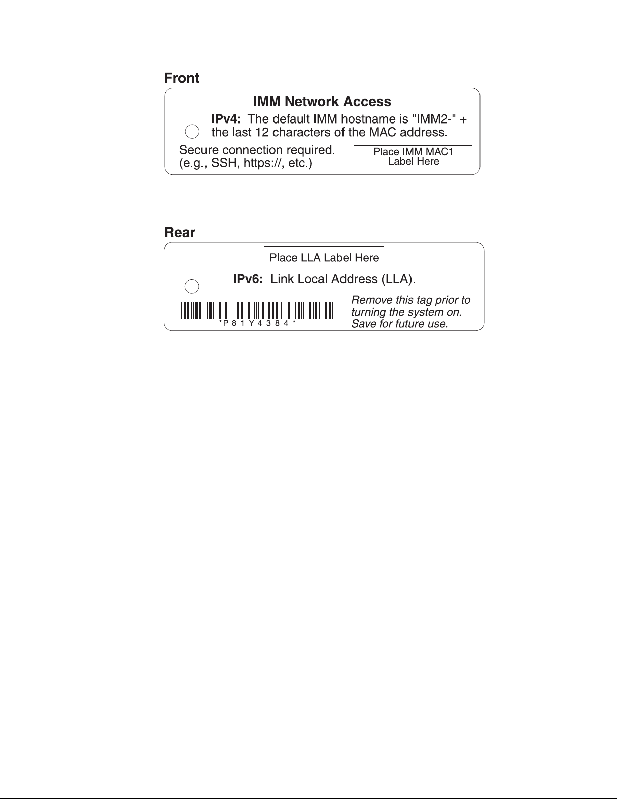
The rear of the network access tag lists the IPv6 link local address (LLA), as shown
in the following illustration.
The MAC address is also available through the Setup utility, the CMM cinstatus
command, and the CMM web interface.
v For more information about the Setup utility, see “Using the Setup utility” on
page 29.
v For more information about the CMM cinstatus command, see the "Flex System
Chassis Management Module: Command-Line Interface Reference Guide" at
http://pic.dhe.ibm.com/infocenter/flexsys/information/topic/
com.ibm.acc.cmm.doc/cli_command_cinstatus.html.
v From the CMM web interface, select Compute Nodes from the Chassis
Management menu. For more information, see the "Flex System Chassis
Management Module: User's Guide" at http://pic.dhe.ibm.com/infocenter/
flexsys/information/topic/com.ibm.acc.cmm.doc/cmm_user_guide.html. All
fields and options are described in the CMM web interface online help.
Note: If the network access tag is missing from the front of the compute node, you
can also locate the MAC address on a label located on the bottom of the compute
node.
Logging on to the web interface
Use these instruction to log in to the IMM2 web interface.
Notes:
v If you are logging on to the IMM2 for the first time after installation, the IMM2
defaults to Dynamic Host Configuration Protocol (DHCP). If a DHCP host is not
available, the IMM2 assigns a static IP address between 192.168.70.101 and
192.168.70.114, depending on the bay in which the compute node is installed.
v You can also assign IP addresses through the CMM ifconfig command. For more
information about the CMM ifconfig command, see the "Flex System Chassis
Management Module: Command-Line Interface Reference Guide" at
http://pic.dhe.ibm.com/infocenter/flexsys/information/topic/
com.ibm.acc.cmm.doc/cli_command_ifconfig.html.
50 Flex System x280 X6, x480 X6, and x880 X6 Compute Node Types 7903 and 4259: Installation and Service Guide
Page 63

v To assign IP addresses from the CMM web interface, click Mgt Module
Management > Network > Ethernet.
v If the CMM and compute nodes are set to use DHCP, and the CMM loses
connectivity to the network, the CMM attempts to acquire a new IP address
when network connectivity is restored. The compute nodes will not attempt to
acquire an IP address again and the compute node continues to use their
existing IP addresses. Therefore, if you experience network problems on
compute nodes after connectivity between the CMM and the network has been
restored, you might need to reset the system-management processor on each of
the compute nodes in the chassis (including Flex System Manager management
software, if it is installed).
v The IMM2 user name and password are provisioned through the CMM. To use
tools such as Advanced Settings Utility (ASU) for out-of-band communications,
you must define local user accounts from the IMM web interface. To define local
user accounts from the IMM web interface, click IMM Management > Users.
The local user accounts are valid only for accessing the IMM web interface on
this compute node. However, if you back up the IMM configuration, that backup
will not contain the local user accounts that were created from the IMM user
interface.
v The IMM2 logs you out of the web interface if your browser is inactive for the
number of minutes that you have specified for the timeout period. To modify
the timeout period, from the IMM web interface, click IMM Management >
User > Global Login Settings > General.
1. Open a web browser and in the Address or URL field, type the IP address or
host name of the IMM2 to which you want to connect. You can determine the
IP address or host name by viewing the network access tag (see “Viewing the
network access tag” on page 49). The IP address and host name can also be
determined by viewing the Integrated Management Module > Network
Configuration section of the Setup utility (see “Using the Setup utility” on
page 29).
2. On the Login page, type the CMM user name and CMM password. You are
then directed to the main page of the IMM2 web interface. If you are using the
IMM2 for the first time, you can obtain the user name and password from your
system administrator. All login attempts are documented in the IMM event log.
IMM2 action descriptions
This topic provides information about the IMM2 functions available from the web
interface.
Navigate to activities you perform with the IMM at the top of the IMM window.
The title bar identifies the user name that is logged in, allows you to configure
Settings for the status screen refresh rate and a custom trespass message, and Log
out of the IMM web interface. Beneath the title bar are tabs that allow you to
access various IMM2 functions, as listed in Table 2 on page 52.
For more information about the IMM2 actions, see http://www.ibm.com/support/
entry/portal/docdisplay?lndocid=MIGR-5086346.
Chapter 4. Accessing the IMM2 51
Page 64

Table 2. IMM2 actions
Tab Selection Description
System Status The System Status page allows you to view system status, active system
events, and hardware health information. It provides quick links to the
Server Power Actions, and Remote Control functions of the Server
Management tab, and allows you to view an image of the last
operating-system-failure screen capture.
Events Event Log The Event Log page displays entries that are currently stored in the IMM
event log. The log includes a text description of system events that are
reported, including information about all remote access attempts and
configuration changes. All events in the log are time stamped, using the
IMM2 date and time settings. Some events also generate alerts, if they are
configured to do so. You can sort and filter events in the event log and
export them to a text file.
Event Recipients The Event Recipients page allows you to manage who will be notified of
system events. It allows you to configure each recipient, and manage
settings that apply to all event recipients. You can also generate a test
event to verify notification feature operation.
Service and
Support
Server Management Server Firmware The Server Firmware page displays firmware levels and allows you to
Download Service
Data
Remote Control The Remote Control page allows you to control the compute node at the
Server Properties The Server Properties page provides access to various properties, status,
Server Power
Actions
Disks The Disks page displays the status of hard disk drives in the system. You
The Download Service Data page creates a compressed file of
information that can be used by Support to assist you.
update the IMM2 firmware, compute node firmware, and DSA firmware.
operating system level. It provides access to both Remote Disk and
Remote Console functionality. You can view and operate the compute
node console from your computer, and you can mount one of your
computer disk drives, such as the CD-ROM drive or the diskette drive,
on the compute node. When you have mounted a disk, you can use it to
restart the compute node and to update firmware on the compute node.
The mounted disk appears as a USB disk drive that is attached to the
compute node.
and settings for your compute node:
v The General Settings tab displays information that identifies the system
to operations and support personnel.
v The LEDs tab displays the status of all system LEDs. It also allows you
to change the state of the location LED.
v The Hardware Information tab displays compute node vital product
data (VPD). The IMM2 collects compute node information, compute
node component information, and network hardware information.
v The Environmentals tab displays voltage and temperature information
for the compute node and the components.
v The Hardware Activity tab displays a history of Field Replacable Unit
(FRU) components that have been added to or removed from the
system.
The Server Power Actions page provides full remote power control over
your compute node with power-on, power-off, and restart actions.
can click on a drive name to display active events for the hard disk
drive.
52 Flex System x280 X6, x480 X6, and x880 X6 Compute Node Types 7903 and 4259: Installation and Service Guide
Page 65

Table 2. IMM2 actions (continued)
Tab Selection Description
Server Management Processors The Processors page displays the microprocessors in the system, along
with their status and rated speed. You can click on a microprocessor
name to display events and additional hardware information for the
microprocessor.
Server Timeouts The Server Timeouts page allows you to manage compute node start
timeouts to detect and recover from compute node hang occurrences.
PXE Network Boot The PXE Network Boot page allows you to change the host compute
node startup (boot) sequence for the next restart to attempt a Preboot
Execution Environment (PXE)/Dynamic Host Configuration Protocol
(DHCP) network startup. The host startup sequence will be altered only
if the host is not under Privileged Access Protection (PAP).
Latest OS Failure
Screen
The Latest OS Failure Screen page displays a screen image, when
available, of the most recent operating system failure on the compute
node. For your IMM to capture operating system failure screens, the
operating system watchdog must be enabled.
Scalable Complex Use the Scalable Complex page to view, create, and manage scalable
complexes. A scalable complex allows compute nodes to be grouped into
a single partition or multiple partitions.
Chapter 4. Accessing the IMM2 53
Page 66

Table 2. IMM2 actions (continued)
Tab Selection Description
IMM Management IMM Properties The IMM Properties page provides access to various properties, status,
and settings for your IMM2:
v The Firmware tab provides a link to the Server Firmware section of
Server Management.
v The IMM Date and Time Settings tab allows you to view and configure
date and time settings for the IMM2.
v The Serial Port tab configures the IMM2 serial port settings. These
settings include the serial port baud rate used by the serial port
redirection function and the key sequence to switch between the serial
redirection and command-line interface (CLI) modes.
Users The Users page allows you to configure the IMM2 login profiles and
global login settings, and to view users that are currently logged in to the
IMM2. Global login settings include enabling Lightweight Directory
Access Protocol (LDAP) compute node authentication, setting the web
inactivity timeout, and customizing the account security settings.
Network The Network Protocol Properties page provides access to networking
properties, status, and settings for your IMM2:
v The Ethernet tab manages how the IMM2 communicates using
Ethernet.
v The SNMP tab configures the SNMPv1 and SNMPv3 agents.
v The DNS tab configures the DNS compute nodes that the IMM2
interacts with.
v The DDNS tab enables or disables and configures Dynamic DNS for
the IMM2.
v The SMTP tab configures SMTP compute node information used for
alerts sent via email.
v The LDAP tab configures user authentication for use with one or more
LDAP compute nodes.
v The Telnet tab manages Telnet access to the IMM2.
v The USB tab controls the USB interface used for in-band
communication between the compute node and the IMM2. These
settings do not affect the USB remote control functions (keyboard,
mouse, and mass storage).
v The Port Assignments tab allows you to change the port numbers used
by some services on the IMM2.
54 Flex System x280 X6, x480 X6, and x880 X6 Compute Node Types 7903 and 4259: Installation and Service Guide
Page 67

Table 2. IMM2 actions (continued)
Tab Selection Description
IMM Management Security The IMM Security page provides access to security properties, status, and
settings for your IMM2:
v The HTTPS Server tab allows you to enable or disable the HTTPS
compute node and manage the certificates.
v The CIM Over HTTPS tab allows you to enable or disable CIM over
HTTPS and manage the certificates.
v The LDAP Client tab allows you to enable or disable LDAP security
and manage the certificates.
v The SSH Server tab allows you to enable or disable the SSH compute
node and manage the certificates.
IMM Configuration The IMM Configuration page displays a summary of the current IMM2
configuration settings. It also provides the following functions:
v Backup the current IMM2 configuration
v Restore a saved IMM2 configuration
v Display backup and restoration status
v Reset the configuration of the IMM2 to the factory defaults.
v Access the IMM2 initial setup wizard
Note: Backups that you make from the IMM user interface will not
contain any local user accounts that were created from the IMM user
interface.
Restart IMM The Restart IMM page allows you to reset the IMM.
Reset IMM to
factory defaults...
Activation Key
Management
The Reset IMM to factory defaults... page allows you to reset the
configuration of the IMM2 to the factory defaults.
Attention: When you click Reset IMM to factory defaults..., all of the
modifications that you made to the IMM2 are lost.
The Activation Key Management page allows you to manage activation
keys for optional IMM2 or compute node Features on Demand (FoD)
features.
Accessing the IMM2 using the LAN over USB interface
Unlike a baseboard management controller, the IMM2 does not require IPMI device
drivers or USB daemons for in-band IMM2 communication. Instead, a LAN over
USB interface enables in-band communication to the IMM2; the IMM2 hardware
on the system board presents an internal Ethernet interface from the IMM2 to the
operating system. LAN over USB is also called the USB in-band interface in the
IMM2 web interface.
The following table shows the IP addresses for the IMM2 and the host.
Table 3. LAN over USB addresses
Keyboard
Controller
IMM2 IP subnet
IMM2 IP address
169.254.95.118 255.255.255.0 169.254.95.120 169.254.95.0/24 255.255.255.0 0x8C80
mask Host address Host subnet
Host subnet
mask
Chapter 4. Accessing the IMM2 55
Style (KCS)
address
Page 68

Potential conflicts with the LAN over USB interface
In some situations, the LAN over USB interface can conflict with certain network
configurations, applications, or both. For example, Open MPI attempts to use all
the available network interfaces on a server or compute node. Open MPI detects
the IMM2 LAN over USB interface and attempts to use it to communicate with
other systems in a clustered environment. The LAN over USB interface is an
internal interface, so this interface does not work for external communication with
other systems in the cluster.
Resolving conflicts with the IMM2 LAN over USB interface
Use any of the following actions to resolve LAN over USB conflicts with network
configurations and applications.
About this task
Use one of the following methods to resolve LAN over USB conflicts.
Note: For conflicts with Open MPI, configure the application so that it does not
attempt to use this interface.
v Take down the interface (run ifdown under Linux).
v Remove the device driver (run rmmod under Linux).
v Disable the LAN over USB interface from the CMM web interface.
Note: You cannot update the firmware for a compute node while the LAN over
USB interface is disabled. Before updating the firmware, you must re-enable the
interface. After updating the firmware, you can disable the interface again.
To disable the LAN over USB interface from the CMM web interface, complete
the following steps.
1. Log in to the CMM web interface.
2. From the CMM web interface homepage click Chassis Management >
Compute Nodes.
3. Click the compute node ID.
4. Click the General tab.
5. Uncheck Enable Ethernet Over USB to disable the LAN over USB interface.
Configuring the LAN over USB interface
An IMM2 must be configured to use the LAN over USB interface. The firmware
update package or Advanced Settings Utility attempts to perform the setup
automatically, if needed. If the automatic setup fails or if you prefer to set up the
LAN over USB manually, use one of the following processes.
For more information about LAN over USB configuration on different operating
systems, see http://www.ibm.com/support/entry/portal/
docdisplay?lndocid=MIGR-5083207.
Installing the LAN over USB Windows device driver
When you install a Windows operating system, there will be an unknown RNDIS
device in the Device Manager. IBM provides a Windows INF file that identifies this
device. The signed version of the INF file is included in all of the Windows
versions of the IMM2, UEFI, and DSA update packages. Complete the following
steps to install ibm_rndis_server_os.inf.
56 Flex System x280 X6, x480 X6, and x880 X6 Compute Node Types 7903 and 4259: Installation and Service Guide
Page 69

Procedure
To install the LAN over USB device driver for Windows, complete the following
steps.
Note: You only have to perform these steps if the compute node is running a
Windows operating system and the ibm_rndis_server_os.inf file has not been
previously installed. The file only has to be installed once. It is required by
Windows operating systems to detect and use the LAN over USB functionality.
1. Obtain a Windows version of the server or compute node UEFI code package
(see “Updating firmware and device drivers” on page 25 for more
information).
2. Extract the ibm_rndis_server_os.inf and device.cat files from the firmware
update package and copy them to the \WINDOWS\inf subdirectory.
Note: You can use the -x path command-line interface option to extract the
files. For more information about this option, see the readme file that comes
with the update package.
3. (Windows 2003) Install the ibm_rndis_server_os.inf file by right-clicking the
file and clicking Install. This generates a PNF file of the same name in
\WINDOWS\inf.
(Windows 2008) Click Computer Management > Device Manager and find
the RNDIS Device. Click Properties > Driver > Reinstall driver. Point the
server or compute node to the \Windows\inf directory where it can find the
ibm_rndis_server_os.inf file and install the device.
4. Click Computer Management > Device Manager. Right-click Network
adapters and select Scan for hardware changes. A small pop-up confirms that
the Ethernet device is found and installed. The New Hardware Wizard starts
automatically.
5. When you are prompted Can Windows connect to Windows Update to search
for software?, select No, not this time. Click Next to continue.
6. When you are prompted What do you want the wizard to do?, select Install
from a list or specific location (Advanced). Click Next to continue.
7. When you are prompted Please choose your search and installation
options, select Don't search. I will choose the driver to install. Click Next to
continue.
8. When you are prompted Select a hardware type, and then click Next,
select Network adapters. Click Next to continue.
9. When you are prompted with the statement Completing the Found New
Hardware Wizard, click Finish. A new local area connection appears. If the
message This connection has limited or no connectivity is displayed,
ignore this message.
10. Return to the Device Manager. IBM USB Remote NDIS Network Device or
Lenovo USB Remote NDIS Network Device appears under Network
Adapters.
11. Use the Setup utility to view or set the IP address. See Table 3 on page 55 for
information about the IP addresses.
Attention: Use only the console breakout cable that comes with the compute
node. Attempting to connect other console breakout cable types might damage
the console breakout cable and the compute node.
a. Connect a keyboard, monitor, and mouse to the console breakout cable and
connect the console breakout cable to the compute node.
Chapter 4. Accessing the IMM2 57
Page 70

b. Turn on the compute node (see “Turning on the compute node” on page
15).
c. When the prompt Press <F1> Setup is displayed, press F1. If you have set
an administrator password, you must type the administrator password to
access the full Setup utility menu. If you do not type the administrator
password, a limited Setup utility menu is available.
d. Select System Settings → Integrated Management Module → Network
Configuration.
e. Locate the IP address.
f. Exit from the Setup utility.
Installing the LAN over USB Linux device driver
Versions of Linux since RHEL5 Update 3 and SLES10 Service Pack 2 support the
LAN over USB interface by default. This interface is detected and displayed during
the installation of these operating systems.
See Table 3 on page 55 for information about the IP addresses.
Note: Older Linux distributions might not detect the LAN over USB interface and
might require manual configuration. For information about configuring LAN over
USB on specific Linux distributions, see http://www.ibm.com/support/entry/
portal/docdisplay?lndocid=MIGR-5083207.
The IMM2 LAN over USB interface requires that the usbnet and cdc_ether device
drivers be loaded. If the drivers have not been installed, use modprobe to install
them. When these drivers are installed, the IMM2 USB network interface is shown
as a network device in the operating system. To discover the name that the
operating system has assigned to the IMM2 USB network interface, type
dmesg | grep -i cdc ether
58 Flex System x280 X6, x480 X6, and x880 X6 Compute Node Types 7903 and 4259: Installation and Service Guide
Page 71

Chapter 5. Parts listing, Types 7903 and 4259
The following replaceable components are available for the Flex System x280 X6,
x480 X6, and x880 X6 Compute Node Types 7903 and 4259.
For an updated parts listing on the web, go to http://www.ibm.com/
supportportal.
Note: The illustrations in this document might differ slightly from your hardware.
1
12
2
2
11
10
7
9
6
8
7
5
3
4
Replaceable components consist of Tier 1 customer replaceable units (CRUs) and
field replaceable units (FRUs):
v Tier 1 customer replaceable unit (CRU): Replacement of Tier 1 CRUs is your
responsibility. If Lenovo installs a Tier 1 CRU at your request without a service
contract, you will be charged for the installation.
v Field replaceable unit (FRU): FRUs must be serviced only by trained service
technicians.
For information about the terms of the warranty and getting service and assistance,
see the Warranty Information document.
© Lenovo 2015. Portions © IBM Corp. 2014. 59
Page 72

Tier 1 CRU
Index Description
Top cover (when ordering this part, order the Label Kit part number
1
00AG903)
2 Air baffle kit 00AG905
3 Flex System FC3172 2-port 8 Gb FC Adapter 69Y1941
3 Flex System IB6132 2-port FDR Infiniband Adapter 00D8532
3 Flex System EN4132 2-port 10 Gb Ethernet Adapter 00D8534
3 Flex System EN2024 4-port 1 Gb Ethernet Adapter 49Y7902
3 Flex System FC3052 2-Port 8 Gb FC Adapter 95Y2378
3 Flex System FC5172 2-Port 16 Gb FC Adapter 69Y1945
3 Flex System CN4022 2-Port 10 Gb Converged Network Adapter 88Y5922
3 Flex System EN6132 2-Port 40 Gb Ethernet Adapter 90Y3485
3 Flex System CN4054R 10 Gb Virtual Fabric Adapter 00Y3309
3 Flex System FC5052 2-Port 16 Gb FC Adapter 95Y2389
3 Flex System FC5054 4-Port 16 Gb FC Adapter 95Y2394
3 Flex System FC5022 2-Port 16 Gb FC Adapter 95Y2396
3 Flex System CN4058 8-Port 10 Gb Virtual Fabric Adapter 94Y5163
4 Memory, 64 GB 8Rx44Gbit DDR-3 1333 MHz 1.35V LP LRDIMM 46W0743
4 Memory, 4 GB 1Rx42Gbit DDR-3 1600 MHz 1.35 LP RDIMM 00D5026
4 Memory, 8 GB 1Rx44Gbit DDR-3 1600 MHz 1.35 LP RDIMM 00D5038
Memory, 16 GB 2Rx44Gbit DDR-3 1600 MHz 1.35V LP RDIMM (Type
4
7903 models A2x, B2x, C2x, D2x, F2x, G2x, H2x, J2x, L2x, M2x, N2x,
Q2x, R2x) (Type 4259 models A2x, D2x, N2x)
4 Memory, 32 GB 4Rx44Gbit DDR-3 1600 MHz 1.35V LP LRDIMM 46W0678
Intel Xeon Processor E7-2850V2 12C 2.3 GHz 24 MB Cache 1600 MHz
5
105W (Type 7903 A2x) (Type 4259 A2x)
Intel Xeon Processor E7-2870V2 15C 2.3 GHz 30 MB Cache 1600 MHz
5
130W
Intel Xeon Processor E7-2880V2 15C 2.5 GHz 37.5 MB Cache 1600 MHz
5
130W (Model B2x)
Intel Xeon Processor E7-2890V2 15C 2.8 GHz 37.5 MB Cache 1600 MHz
5
155W (Model C2x)
Intel Xeon Processor E7-4809V2 6C 1.9 GHz 12MB Cache 1333 MHz
5
105W (Type 7903 D2x) (Type 4259 D2x)
Intel Xeon Processor E7-4820V2 8C 2.0 GHz 16 MB Cache 1600 MHz
5
105W (Model F2x)
Intel Xeon Processor E7-4830V2 10C 2.2 GHz 20 MB Cache 1600 MHz
5
105W (Model G2x)
Intel Xeon Processor E7-4850V2 12C 2.3 GHz 24 MB Cache 1600 MHz
5
105W (Model H2x)
Intel Xeon Processor E7-4860V2 12C 2.6 GHz 30MB Cache 1600 MHz
5
130W
Intel Xeon Processor E7-4870V2 15C 2.3 GHz 30 MB Cache 1600 MHz
5
130W (Model J2x)
part number
00AG908
46W0674
FRU part
number
00Y3968
00Y3974
00Y3980
00Y3986
44X3963
44X3968
44X3973
44X3978
44X3983
44X3988
60 Flex System x280 X6, x480 X6, and x880 X6 Compute Node Types 7903 and 4259: Installation and Service Guide
Page 73

Tier 1 CRU
Index Description
Intel Xeon Processor E7-4880V2 15C 2.5 GHz 37.5 MB Cache 1600 MHz
5
130W (Model L2x)
Intel Xeon Processor E7-4890V2 15C 2.8 GHz 37.5 MB Cache 1600 MHz
5
155W (Model M2x)
Intel Xeon Processor E7-8850V2 12C 2.3 GHz 24 MB Cache 1600 MHz
5
105W (Type 7903 N2x) (Type 4259 N2x)
Intel Xeon Processor E7-8893V2 6C 3.4 GHz 37.5 MB Cache 1600 MHz
5
155W (Model RDx)
Intel Xeon Processor E7-8870V2 15C 2.3 GHz 30 MB Cache 1600 MHz
5
130W
Intel Xeon Processor E7-8880V2 15C 2.5 GHz 37.5 MB Cache 1600 MHz
5
130W (Model Q2x)
Intel Xeon Processor E7-8890V2 15C 2.8 GHz 37.5 MB Cache 1600 MHz
5
155W ( Model R2x)
Intel Xeon Processor E7-8891V2 10C 3.2 GHz 37.5 MB Cache 1600 MHz
5
155W
Intel Xeon Processor E7-8857V2 12C 3.0 GHz 30 MB Cache 1600 MHz
5
130W
Intel Xeon Processor E7-8880LV2 12C 3.0 GHz 30 MB Cache 1600 MHz
5
130W
part number
6 Filler, 2.5 inch hard disk drive bay 00FW856
7 Bezel, front assembly kit 00AG909
8 SMP filler 00AG911
9 Center partition 00AG904
10 Hard disk drive, 500 GB 7.2K NL 6 Gbps SAS 2.5 inch G3 hot-swap 00AJ122
10 Hard disk drive, 1 TB 7.2K NL 6 Gbps SAS 2.5 inch G3 hot-swap 00AJ087
10 Hard disk drive, 300 GB 10K 6 Gbps SAS 2.5 inch G3 hot-swap 00AJ097
10 Hard disk drive, 600 GB 10K 6 Gbps SAS 2.5 inch G3 hot-swap 00AJ092
10 Hard disk drive, 900 GB 10K 6 Gbps SAS 2.5 inch G3 hot-swap 00AJ072
10 Hard disk drive, 1.2 TB 10K 6 Gbps SAS 2.5 inch G3 hot-swap 00AJ147
10 Hard disk drive, 146 GB 15K 6 Gbps SAS 2.5 inch G3 hot-swap 00AJ112
10 Hard disk drive, 300 GB 15K 6 Gbps SAS 2.5 inch G3 hot-swap 00AJ082
10 Hard disk drive, 600 GB 15K 6 Gbps SAS 2.5 inch G3 hot-swap 00AJ127
10 Hard disk drive, 250 GB 7.2K NL 6 Gbps SATA 2.5 inch G3 hot-swap 00AJ132
10 Hard disk drive, 500 GB 7.2K NL 6 Gbps SATA 2.5 inch G3 hot-swap 00AJ137
10 Hard disk drive, 1 TB 7.2K NL 6 Gbps SATA 2.5 inch G3 hot-swap 00AJ142
10 Self encrypting drive, 146 GB 15K 6 Gbps SAS 2.5 inch G3 hot-swap 00AJ117
10 Self encrypting drive, 300 GB 10K 6 Gbps SAS 2.5 inch G3 hot-swap 00AJ107
10 Self encrypting drive, 600 GB 10K 6 Gbps SAS 2.5 inch G3 hot-swap 00AJ102
10 Self encrypting drive, 900 GB 10K 6 Gbps SAS 2.5 inch G3 hot-swap 00AJ077
10 Self encrypting drive, 1.2 TB 10K 6 Gbps SAS 2.5 inch G3 hot-swap 00AJ152
Hard Disk Drive Backplane, SAS single 2.5 inch (Type 7903 models A2x,
11
B2x, C2x, D2x, F2x, G2x, H2x, J2x, L2x, M2x, N2x, Q2x, R2x) (Type 4259
00Y3878
models A2x, D2x, N2x)
FRU part
number
44X3993
44X3998
44X4003
44X4008
44X4013
44X4018
44X4023
44X4028
44X4033
44X4038
Chapter 5. Parts listing, Types 7903 and 4259 61
Page 74

Tier 1 CRU
Index Description
12 Heat sink, microprocessor 00AG887
2 GB USB Memory Key 42D0545
Alcohol wipes 59P4739
Flex System console breakout cable (models AC1, MC1, CTO) 81Y5287
Light path LED card 81Y5290
RFID label tag assembly - EMEA 00E6323
RFID label tag assembly - US 74Y8800
Thermal grease kit 41Y9292
Adapter connector retention kit 00AG916
Base assembly (includes chassis and system board) (Type 7903 models
A2x, B2x, C2x, D2x, F2x, G2x, H2x, J2x, L2x, M2x, N2x, Q2x, R2x) (Type
4259 models A2x, D2x, N2x)
Fabric connector (Type 4259, model D4x) (Type 7903, model A4x, B4x,
C4x, D4x, F4x, G4x, H4x, J4x, L4x, M4x, N4x, Q4x, R4x, RDx)
Solid state drive, S3700 200 GB 6 Gbps SAS 2.5 inch G3 hot-swap 00AJ157
Solid state drive, S3700 400 GB 6 Gbps SAS 2.5 inch G3 hot-swap 00AJ162
Solid state drive, S3700 800 GB 6 Gbps SAS 2.5 inch G3 hot-swap 00AJ167
Solid state drive, 200 GB SAS 2.5 inch Enterprise MLC G3 hot-swap 00AJ208
Solid state drive, 400 GB SAS 2.5 inch Enterprise MLC G3 hot-swap 00AJ213
Solid state drive, 800 GB SAS 2.5 inch Enterprise MLC G3 hot-swap 00AJ218
Solid state drive, 1.6 TB SAS 2.5 inch Enterprise MLC G3 hot-swap 00AJ223
Solid state drive, 120 GB SATA 2.5 inch Enterprise MLC G3 hot-swap 00AJ396
Solid state drive, 240 GB SATA 2.5 inch Enterprise MLC G3 hot-swap 00AJ401
Solid state drive, 480 GB SATA 2.5 inch Enterprise MLC G3 hot-swap 00AJ406
Solid state drive, 800 GB SATA 2.5 inch Enterprise MLC G3 hot-swap 00AJ411
Solid state drive, S3700 200 GB SATA 1.8 inch Enterprise MLC G3
hot-swap
Solid state drive, S3700 400 GB SATA 1.8 inch Enterprise MLC G3
hot-swap
Solid state drive, S3500 80 GB SATA 1.8 inch Enterprise Value MLC G3
hot-swap
Solid state drive, S3500 240 GB SATA 1.8 inch Enterprise Value MLC G3
hot-swap
Solid state drive, S3500 800 GB SATA 1.8 inch Enterprise ValueMLC G3
hot-swap
Solid state drive, S3500 400 GB SATA 1.8 inch Enterprise ValueMLC G3
hot-swap
Flex System x480 X6 4-Socket Scalability Connector 00Y3872
Flex System x880 X6 8-Socket Scalability Connector 00Y3875
Label Kit 00AG903
Microprocessor installation tool 94Y9971
Miscellaneous parts kit 00AG910
CMOS battery, 3.0 volt (all models) 33F8354
part number
81Y5175
41Y8367
41Y8372
00AJ041
00AJ046
00AJ456
00AJ051
FRU part
number
47C2240
62 Flex System x280 X6, x480 X6, and x880 X6 Compute Node Types 7903 and 4259: Installation and Service Guide
Page 75

Index Description
CRM handle kit 00AG915
Rear bulkhead assembly full wide 46M2833
1.8-inch SSD cage (includes two mounting sleeves and two SSD bezels) 00AG919
ServeRAID M1200 Series 1.8-inch SSD backplane 00AG922
ServeRAID M5100 1.8-inch drive cage 00Y3881
ServeRAID M5100 Series flex paddle card and cable assembly 00FE033
ServeRAID M5100 Series air baffle kit (includes left air baffle, right air
baffle, and center partition)
ServeRAID M5100 Series power cable 00AF857
ServeRAID M5100 Series solid state drive Flex expansion cable 00D5078
ServeRAID M5100 Series flash power module 00JY023
ServeRAID M5115 SAS/SATA RAID Controller 47C8806
Tier 1 CRU
part number
00AG934
FRU part
number
Chapter 5. Parts listing, Types 7903 and 4259 63
Page 76

64 Flex System x280 X6, x480 X6, and x880 X6 Compute Node Types 7903 and 4259: Installation and Service Guide
Page 77

Chapter 6. Troubleshooting
Use this information to diagnose and correct problems that might occur in your
Flex System x280 X6, x480 X6, and x880 X6 Compute Node Types 7903 and 4259.
The information in this section describes tools and procedures for solving
hardware and software problems. If you cannot diagnose and correct a problem by
using the information, see “Getting help and technical assistance,” on page 773 for
more information.
Service bulletins
Lenovo continually updates the support website with tips and techniques that you
can use to solve problems that you might have with the Flex System x280 X6, x480
X6, and x880 X6 Compute Node Types 7903 and 4259.
To find service bulletins that are available for the Flex System x280 X6, x480 X6,
and x880 X6 Compute Node Types 7903 and 4259, go to http://www.ibm.com/
supportportal and search for the terms 7903 or 4259 and retain.
Diagnostic tools
Use this information to review the diagnostic tools to diagnose and solve
hardware-related problems.
Light path diagnostics
Use this information as an overview of light path diagnostics.
Light path diagnostics is a system of LEDs above the control panel and on various
internal components of the compute node. When an error occurs, LEDs can be lit
throughout the compute node to help identify the source of the error.
Viewing the light path diagnostics LEDs
Use this information to locate and identify the light path diagnostics LEDs.
Before you work inside the compute node to view light path diagnostics LEDs,
read “Safety” on page v and “Installation guidelines” on page 699.
If an error occurs, view the light path diagnostics LEDs in the following order:
1. Look at the control panel on the front of the compute node.
Hard disk
drive activity
LED
Identify
LED
Check log
LED
Fault
LED
Scaling
LED
© Lenovo 2015. Portions © IBM Corp. 2014. 65
Page 78

v If the check log LED is lit, it indicates that a condition that causes an event
to log in the IMM event log has occurred.
v If the fault LED is lit, it indicates that an error has occurred; view the light
path diagnostics panel and LEDs to isolate the failing component.
2. To view the light path diagnostics LEDs, select one of the following procedures:
v You can view the LEDs through the CMM led command, the CMM web
interface, or Flex System Manager management software.
– For more information about the CMM led command, see the "Flex System
Chassis Management Module: Command-Line Interface Reference Guide"
at http://pic.dhe.ibm.com/infocenter/flexsys/information/topic/
com.ibm.acc.cmm.doc/cli_command_led.html.
– From the CMM web interface, select Compute Nodes from the Chassis
Management menu. For more information, see the "Flex System Chassis
Management Module: User's Guide" at http://pic.dhe.ibm.com/
infocenter/flexsys/information/topic/com.ibm.acc.cmm.doc/
cmm_user_guide.html. All fields and options are described in the CMM
web interface online help. See Starting the web interface in the "Flex
System Chassis Management Module: User's Guide" at
http://pic.dhe.ibm.com/infocenter/flexsys/information/topic/
com.ibm.acc.cmm.doc/cmm_ug_startwebinterface.html for information
about starting the CMM web interface.
– For more information about Flex System Manager management software,
see the "Flex System Manager Software: Installation and Service Guide" at
http://pic.dhe.ibm.com/infocenter/flexsys/information/topic/
com.ibm.acc.8731.doc/product_page.html.
v If you are in the same location as the compute node, you can complete the
following steps:
a. Remove the compute node from the Flex System chassis, (see “Removing
a compute node from a chassis” on page 701 for instructions).
b. Carefully lay the compute node on a flat, static-protective surface.
c. Open the compute node cover (see “Removing the compute node cover”
on page 715 for instructions).
d. Remove the air baffles that are installed over the DIMM connectors.
e. Press the power button. When you press the power button, LEDs on the
light path diagnostics panel and the system board will be lit if there are
any hardware-related issues.
Note: The power source for light path diagnostics is designed to last only
a short time. If you press the power button and the light path diagnostics
LED lights, light path diagnostics is charged to light the LEDs.
The following illustration shows the LEDs on the light path diagnostics panel.
66 Flex System x280 X6, x480 X6, and x880 X6 Compute Node Types 7903 and 4259: Installation and Service Guide
Page 79

Light path diagnostics
System board
Mismatch
NMI
Temperature
Memory
Future use only
The following illustration shows the locations of the light path diagnostics LEDs
on the system board.
Light path diagnostics LEDs
Use this information to diagnose possible errors that are indicated by the light path
diagnostics LEDs.
The following table describes the LEDs on the light path diagnostics panel and the
light path diagnostics LEDs on the system board. LEDs on the light path
diagnostics panel are visible from the top of the compute node. See “Viewing the
light path diagnostics LEDs” on page 65 for information about lighting the LEDs.
Chapter 6. Troubleshooting 67
Page 80

Table 4. Light path diagnostics LEDs
Lit light path diagnostics LED Description
None The compute node is not sufficiently charged to display the LEDs on the system
board.
Battery error The system CMOS battery is not installed or is not working.
BMC error Future use only.
DC power error Future use only.
DIMM x error A memory error occurred.
Light path diagnostics The power source for the light path diagnostics LEDs is charged.
Light path diagnostics only No errors have occurred.
Memory A memory error has occurred.
Microprocessor x error The IMM2 lights this LED when a microprocessor has failed or overheated or the
start microprocessor (CPU 1) is missing. The fault LED on the front panel is also
lit.
Mismatch The microprocessors are mismatched. If the Memory LED is also lit, the DIMMs
are mismatched.
NMI The system board has failed.
SAS/SATA backplane error A hard disk drive backplane error has occurred.
System board The system board has failed.
Temperature The system temperature has exceeded a threshold level.
IMM event log
Use this information as an overview of the IMM event log.
The integrated management module II (IMM2) consolidates the
system-management processor functionality, video controller, and remote presence
capabilities in a single chip on the system board. The IMM2 monitors all
components of the compute node and posts events in the IMM event log. In
addition, most events are also sent to the Chassis Management Module event log.
You can view the IMM event log through the Dynamic System Analysis (DSA)
program (as the ASM event log).
To diagnose and resolve IMM error codes, see “IMM messages” on page 179.
Viewing event logs through the Setup utility
You can view the IMM and POST events through the Setup utility.
Procedure
To view the POST event log or system-event log, complete the following steps:
1. Connect a keyboard, monitor, and mouse to the console breakout cable and
connect the console breakout cable to the compute node.
Attention: Use only the console breakout cable that comes with the compute
node. Attempting to connect other console breakout cable types might damage
the console breakout cable and the compute node.
2. Turn on the compute node.
68 Flex System x280 X6, x480 X6, and x880 X6 Compute Node Types 7903 and 4259: Installation and Service Guide
Page 81

3. When the prompt <F1> Setup is displayed, press F1. If you have set both a
power-on password and an administrator password, you must type the
administrator password to view the event logs.
4. Select System Event Logs and use one of the following procedures:
v To view the POST event log, select POST Event Viewer.
v To view the system-event log, select System Event Log.
Viewing event logs without restarting the compute node
Methods are available for you to view one or more event logs without having to
restart the compute node.
You can view the Chassis Management Module event log in the Flex System
Manager Chassis Manager, or through the Event Log link in Flex System Manager
management software. For more information about Flex System Manager
management software, see the "Flex System Manager Software: Installation and
Service Guide" at http://pic.dhe.ibm.com/infocenter/flexsys/information/topic/
com.ibm.acc.8731.doc/product_page.html.
You can also view the Chassis Management Module event log through the Event
Log link by using the CMM displaylog command or the CMM web interface.
Note: If event IDs are not currently displayed in the Event Log page, you can
enable them. To do so, click Filter Events and select the Event ID check box under
Visible columns.
v For more information about the CMM displaylog command, see the "Flex
System Chassis Management Module: Command-Line Interface Reference
Guide" at http://pic.dhe.ibm.com/infocenter/flexsys/information/topic/
com.ibm.acc.cmm.doc/cli_command_displaylog.html.
v From the CMM web interface, select Event Log from the Events menu. You can
also view events and their messages by clicking the Active Events tab on the
System Status page. For more information, see the "Flex System Chassis
Management Module: User's Guide" at http://pic.dhe.ibm.com/infocenter/
flexsys/information/topic/com.ibm.acc.cmm.doc/cmm_user_guide.html. All
fields and options are described in the CMM web interface online help.
Note: If event IDs are not currently displayed in the Event Log page, you can
enable them. To do so, click Filter Events and select the Event ID check box
under Visible columns.
If you have installed DSA Portable Edition, you can use it to view the
system-event log (as the IPMI event log), the operating-system event logs, or the
merged DSA log. You can also use DSA Preboot to view these logs, although you
must restart the compute node to use DSA Preboot. To install Portable DSA or DSA
Preboot or to download a DSA Preboot CD image, go to http://www.ibm.com/
support/entry/portal/docdisplay?lndocid=SERV-DSA.
If IPMItool is installed in the compute node, you can use it to view the
system-event log. Most recent versions of the Linux operating system come with a
current version of IPMItool. For information about IPMItool, complete the
following steps.
Note: Changes are made periodically to the Lenovo website. The actual procedure
might vary slightly from what is described in this document.
1. Go to http://www.ibm.com/developerworks.
Chapter 6. Troubleshooting 69
Page 82

2. Click Linux.
3. Click the Linux blueprints tab.
4. Click Blueprints for Linux on IBM systems or Blueprints for Linux on
Lenovo systems, and then click Using Intelligent Platform Management
Interface (IPMI) on IBM Linux platforms or Using Intelligent Platform
Management Interface (IPMI) on Lenovo Linux platforms.
The following table describes the methods that you can use to view the event logs,
depending on the condition of the compute node. The first two conditions
generally do not require that you restart the compute node.
Table 5. Methods for viewing event logs
Condition Action
The compute node is not hung and is
connected to a network.
The compute node is not hung and is not
connected to a network.
The compute node is hung. Use any of the following methods:
Use any of the following methods:
v In a web browser, type the IP address of
the Chassis Management Module and go
to the Event Log page.
v Run Portable or Installable DSA to view
the event logs or create an output file that
you can send to Support.
v Use IPMItool to view the system-event
log.
Use IPMItool locally to view the
system-event log.
v If DSA Preboot is installed, restart the
compute node and press F2 to start DSA
Preboot and view the event logs.
v If DSA Preboot is not installed, insert the
DSA Preboot CD and restart the compute
node to start DSA Preboot and view the
event logs.
v Alternatively, you can restart the compute
node and press F1 to start the Setup
utility and view the POST event log or
system-event log. For more information,
see “Viewing event logs through the
Setup utility” on page 68.
Lenovo Dynamic System Analysis Preboot diagnostic program
Lenovo Dynamic System Analysis (DSA) Preboot diagnostic program collects and
analyzes system information to aid in diagnosing compute node problems.
DSA Preboot performs the following tasks:
v Collects system information into a compressed XML file that you can send to
Support
v Provides a bootable image that you can use to run extended hardware tests
independent of the operating system or applications
v Collects the version and license information from local VMware ESXi hypervisor
software
Notes:
70 Flex System x280 X6, x480 X6, and x880 X6 Compute Node Types 7903 and 4259: Installation and Service Guide
Page 83

1. DSA Preboot might appear to be unresponsive when you start the program.
This is normal operation while the program loads.
2. In a multi-node complex, each node has a unique DSA interface. You can view
node-specific information, such as error logs, from the unique DSA interface.
To obtain DSA code and the Dynamic System Analysis Installation and User's Guide,
go to http://www.ibm.com/support/entry/portal/docdisplay?lndocid=SERV-DSA.
To diagnose and resolve DSA messages, see “DSA diagnostic test results” on page
72.
Running DSA Preboot
Use this information to run DSA Preboot.
About this task
To run the DSA Preboot diagnostic programs, complete the following steps:
1. If the compute node is turned on, turn off the compute node (see “Turning off
the compute node” on page 16).
Attention: Use only the console breakout cable that comes with the compute
node. Attempting to connect other console breakout cable types might damage
the console breakout cable and the compute node.
2. If necessary, connect a keyboard, monitor, and mouse to the console breakout
cable and connect the console breakout cable to the compute node.
3. Turn on the compute node (see “Turning on the compute node” on page 15).
4. When the prompt <F2> Diagnostics is displayed, press F2.
Note: DSA Preboot might appear to be unresponsive for an unusual length of
time when you start the program. This is normal operation while the program
loads.
5. Select Quit from the actions available on the Memory Test screen. You must
exit the Memory Test screen before you can restart the compute node and start
DSA.
Note: After you exit the Memory Test screen, you must restart the compute
node to access the stand-alone memory diagnostic environment again.
6. Enter gui to start the DSA graphical user interface, or select cmd to display the
DSA interactive menu.
7. From the diagnostic programs screen, select the test that you want to run, and
follow the instructions on the screen. For additional information, see the
Dynamic System Analysis Installation and User's Guide, which is available at
http://www.ibm.com/support/entry/portal/docdisplay?lndocid=SERV-DSA.
Help for DSA is available. For help about the DSA CLI, enter help in the command
line. For help with the DSA user interface, press F1. Pressing F1 within a help
panel displays additional online documentation.
Diagnostic text messages
Use this information to understand the diagnostic text messages that are displayed
while the tests are running.
A diagnostic text message contains one of the following results:
v Passed: The test was completed without any errors.
Chapter 6. Troubleshooting 71
Page 84

089-000-000
v Failed: The test detected an error.
v User Aborted: You stopped the test before it was completed.
v Not Applicable: You attempted to test a device that is not present in the
compute node.
v Aborted: The test could not proceed because of the compute node configuration.
v Warning: The test could not be run. There was no failure of the hardware that
was being tested, but there might be a hardware failure elsewhere, or another
problem prevented the test from running; for example, there might be a
configuration problem, or the hardware might be missing or is not being
recognized.
The result is followed by an error code or other additional information about the
error.
Viewing the test results
Use this information to view the test results.
About this task
You can use one of the following methods to access the test log when the tests are
completed:
v From the DSA command line, issue the DSA CLI View command or select the
Diagnostic Event Log option from the DSA graphical user interface (GUI).
v From the DSA interactive menu, select the getextendedresults option.
v From the DSA interactive menu, select the View option to view all of the
collected results and error log data.
v In the DSA GUI, select DSA Error Log from the System Information page.
You can send the DSA error log file to Support to aid in diagnosing the compute
node problems, or you can use the DSA CLI copy command to copy the log to an
external USB device.
DSA diagnostic test results
After running the DSA diagnostic tests, use this information to resolve any issues
that were found.
DSA CPU stress test results
The following messages can result when you run the CPU stress test.
089-000-000 CPU Stress Test Passed
Explanation: CPU Stress Test Passed.
Severity: Event
Serviceable: No
Recoverable: No
Automatically notify Support: No
Related Links:
v IBM Support Website
v Latest level of DSA
v Latest level of BMC/IMM
72
Flex System x280 X6, x480 X6, and x880 X6 Compute Node Types 7903 and 4259: Installation and Service Guide
Page 85

089-801-000 • 089-802-000
089-801-000 CPU Stress Test Aborted
Explanation: CPU Stress Test Aborted. Internal Program Error.
Severity: Warning
Serviceable: Yes
Recoverable: No
Automatically notify Support: No
User response: Complete the following steps:
1. Turn off and restart the system.
2. Make sure that the DSA Diagnostic code is at the latest level.
3. Run the test again.
4. Check system firmware level and upgrade if necessary. The installed firmware level can be found in the DSA
Diagnostic Event Log within the Firmware/VPD section for this component. The latest level firmware for this
component can be found in reference to this system type at the IBM Support website: http://www.ibm.com/
support/docview.wss?uid=psg1MIGR-4JTS2T.
5. Run the test again.
6. If the system has stopped responding, turn off and restart the system and then run the test again.
7. If failure remains, refer to "Troubleshooting by symptom" in the system "Installation and Service Guide" for the
next corrective action.
Related Links:
v IBM Support Website
v Latest level of DSA
v Latest level of BMC/IMM
089-802-000 CPU Stress Test Aborted
Explanation: CPU Stress Test Aborted. System resource unavailability error.
Severity: Warning
Serviceable: Yes
Recoverable: No
Automatically notify Support: No
User response: Complete the following steps:
1. Turn off and restart the system.
2. Make sure that the DSA Diagnostic code is at the latest level.
3. Run the test again.
4. Check system firmware level and upgrade if necessary. The installed firmware level can be found in the DSA
Diagnostic Event Log within the Firmware/VPD section for this component.
5. Run the test again.
6. If the system has stopped responding, turn off and restart the system and then run the test again.
7. If failure remains, refer to "Troubleshooting by symptom" in the system "Installation and Service Guide" for the
next corrective action.
Related Links:
v IBM Support Website
v Latest level of DSA
v Latest level of BMC/IMM
Chapter 6. Troubleshooting 73
Page 86

089-803-000 • 089-901-000
089-803-000 CPU Stress Test Aborted
Explanation: CPU Stress Test Aborted. Memory size is insufficient to run the test. At least 1GB is required.
Severity: Warning
Serviceable: Yes
Recoverable: No
Automatically notify Support: No
Related Links:
v IBM Support Website
v Latest level of DSA
v Latest level of BMC/IMM
089-804-000 CPU Stress Test Aborted
Explanation: CPU Stress Test Aborted. User pressed Ctrl-C.
Severity: Warning
Serviceable: Yes
Recoverable: No
Automatically notify Support: No
Related Links:
v IBM Support Website
v Latest level of DSA
v Latest level of BMC/IMM
089-901-000 CPU Stress Test Failed
Explanation: CPU Stress Test Failed.
Severity: Error
Serviceable: Yes
Recoverable: No
Automatically notify Support: No
User response: Complete the following steps:
1. If the system has stopped responding, turn off and restart the system and then run the test again.
2. Make sure that the DSA Diagnostic code is at the latest level.
3. Run the test again.
4. Check system firmware level and upgrade if necessary. The installed firmware level can be found in the DSA
Diagnostic Event Log within the Firmware/VPD section for this component.
5. Run the test again.
6. If the system has stopped responding, turn off and restart the system and then run the test again.
7. If failure remains, refer to "Troubleshooting by symptom" in the system "Installation and Service Guide" for the
next corrective action.
Related Links:
v IBM Support Website
v Latest level of DSA
v Latest level of BMC/IMM
DSA memory stress test results
The following messages can result when you run the memory stress test.
74
Flex System x280 X6, x480 X6, and x880 X6 Compute Node Types 7903 and 4259: Installation and Service Guide
Page 87

202-000-000 • 202-802-000
202-000-000 MemStr Test Passed
Explanation: Test Passed.
Severity: Event
Serviceable: No
Recoverable: No
Automatically notify Support: No
Related Links:
v IBM Support Website
v Latest level of DSA
v Latest level of BMC/IMM
202-801-000 MemStr Test Aborted
Explanation: Internal program error.
Severity: Warning
Serviceable: Yes
Recoverable: No
Automatically notify Support: No
User response: Complete the following steps:
1. Turn off and restart the system.
2. Make sure that the DSA Diagnostic code is at the latest level.
3. Run the test again.
4. If the system has stopped responding, turn off and restart the system.
5. Check the system firmware level and upgrade if necessary.
6. Run the memory diagnostic to identify the specific failing DIMM.
7. If the failure remains, refer to "Troubleshooting by symptom" in the system "Installation and Service Guide" for
the next corrective action.
Related Links:
v IBM Support Website
v Latest level of DSA
v Latest level of BMC/IMM
202-802-000 MemStr Test Aborted
Explanation: Memory size is insufficient to run the test. At least 1 GB is required.
Severity: Warning
Serviceable: Yes
Recoverable: No
Automatically notify Support: No
Related Links:
v IBM Support Website
v Latest level of DSA
v Latest level of BMC/IMM
Chapter 6. Troubleshooting 75
Page 88

202-803-000 • 202-902-000
202-803-000 MemStr Test Aborted
Explanation: User pressed Ctrl-C.
Severity: Warning
Serviceable: Yes
Recoverable: No
Automatically notify Support: No
Related Links:
v IBM Support Website
v Latest level of DSA
v Latest level of BMC/IMM
202-901-000 MemStr Test Failed
Explanation: Test Failed.
Severity: Error
Serviceable: Yes
Recoverable: No
Automatically notify Support: No
User response: Complete the following steps:
1. Execute the standard DSA memory diagnostics to validate all memory.
2. Make sure that the DSA Diagnostic code is at the latest level.
3. Turn off the system and disconnect it from power.
4. Reseat the memory cards and DIMMs.
5. Reconnect the system to power and turn the system on.
6. Run the test again.
7. Execute the standard DSA memory diagnostics to validate all memory.
8. If the failure remains, refer to "Troubleshooting by symptom" in the system "Installation and Service Guide" for
the next corrective action.
Related Links:
v IBM Support Website
v Latest level of DSA
v Latest level of BMC/IMM
202-902-000 MemStr Test Failed
Explanation: Memory size is insufficient to run the test.
Severity: Error
Serviceable: Yes
Recoverable: No
Automatically notify Support: No
User response: Complete the following steps:
1. Ensure that all memory is enabled by checking the "Available System Memory" in the "Resource Utilization"
section of the DSA Diagnostic Event log.
2. If necessary, access the Configuration/Setup Utility program by pressing F1 during system boot and enable all
memory.
3. Make sure that the DSA Diagnostic code is at the latest level.
76
Flex System x280 X6, x480 X6, and x880 X6 Compute Node Types 7903 and 4259: Installation and Service Guide
Page 89

201-000-000 • 201-000-002
4. Run the test again.
5. Execute the standard DSA memory diagnostics to validate all memory.
6. If the failure remains, refer to "Troubleshooting by symptom" in the system "Installation and Service Guide" for
the next corrective action.
Related Links:
v IBM Support Website
v Latest level of DSA
v Latest level of BMC/IMM
DSA memory isolation test results
The following messages can result when you run the memory isolation test.
201-000-000 Standalone Memory Test Passed
Explanation: Quick/Full Memory Test All CPUs Passed.
Severity: Event
Serviceable: No
Recoverable: No
Automatically notify Support: No
Related Links:
v IBM Support Website
v Latest level of DSA
v Latest level of BMC/IMM
201-000-001 Standalone Memory Test Passed
Explanation: Quick/Full Memory Test CPU 1 Passed.
Severity: Event
Serviceable: No
Recoverable: No
Automatically notify Support: No
Related Links:
v IBM Support Website
v Latest level of DSA
v Latest level of BMC/IMM
201-000-002 Standalone Memory Test Passed
Explanation: Quick/Full Memory Test CPU 2 Passed.
Severity: Event
Serviceable: No
Recoverable: No
Automatically notify Support: No
Related Links:
v IBM Support Website
v Latest level of DSA
v Latest level of BMC/IMM
Chapter 6. Troubleshooting 77
Page 90

201-000-003 • 201-811-001
201-000-003 Standalone Memory Test Passed
Explanation: Quick/Full Memory Test CPU 3 Passed.
Severity: Event
Serviceable: No
Recoverable: No
Automatically notify Support: No
Related Links:
v IBM Support Website
v Latest level of DSA
v Latest level of BMC/IMM
201-000-004 Standalone Memory Test Passed
Explanation: Quick/Full Memory Test CPU 4 Passed.
Severity: Event
Serviceable: No
Recoverable: No
Automatically notify Support: No
Related Links:
v IBM Support Website
v Latest level of DSA
v Latest level of BMC/IMM
201-811-000 Standalone Memory Test Aborted
Explanation: Unable to Locate SMBIOS key "_SM_".
Severity: Warning
Serviceable: No
Recoverable: No
Automatically notify Support: No
User response: Complete the following steps:
1. Perform the actions mentioned one at a time and try the test after each action.
2. If the problem remains, contact your technical-service representative.
3. Turn off the system and disconnect it from power. Wait for 45 seconds. Reseat DIMM(s). Reconnect it to power.
4. Make sure that DSA and BIOS/uEFI are at the latest level.
Related Links:
v IBM Support Website
v Latest level of DSA
v Latest level of BMC/IMM
201-811-001 Standalone Memory Test Aborted
Explanation: Unable to Locate SMBIOS key "_SM_".
Severity: Warning
Serviceable: No
Recoverable: No
78
Flex System x280 X6, x480 X6, and x880 X6 Compute Node Types 7903 and 4259: Installation and Service Guide
Page 91

201-811-002 • 201-811-003
Automatically notify Support: No
User response: Complete the following steps:
1. Perform the actions mentioned one at a time and try the test after each action.
2. If the problem remains, contact your technical-service representative.
3. Turn off the system and disconnect it from power. Wait for 45 seconds. Reseat DIMM(s). Reconnect it to power.
4. Make sure that DSA and BIOS/uEFI are at the latest level.
Related Links:
v IBM Support Website
v Latest level of DSA
v Latest level of BMC/IMM
201-811-002 Standalone Memory Test Aborted
Explanation: Unable to Locate SMBIOS key "_SM_".
Severity: Warning
Serviceable: No
Recoverable: No
Automatically notify Support: No
User response: Complete the following steps:
1. Perform the actions mentioned one at a time and try the test after each action.
2. If the problem remains, contact your technical-service representative.
3. Turn off the system and disconnect it from power. Wait for 45 seconds. Reseat DIMM(s). Reconnect it to power.
4. Make sure that DSA and BIOS/uEFI are at the latest level.
Related Links:
v IBM Support Website
v Latest level of DSA
v Latest level of BMC/IMM
201-811-003 Standalone Memory Test Aborted
Explanation: Unable to Locate SMBIOS key "_SM_".
Severity: Warning
Serviceable: No
Recoverable: No
Automatically notify Support: No
User response: Complete the following steps:
1. Perform the actions mentioned one at a time and try the test after each action.
2. If the problem remains, contact your technical-service representative.
3. Turn off the system and disconnect it from power. Wait for 45 seconds. Reseat DIMM(s). Reconnect it to power.
4. Make sure that DSA and BIOS/uEFI are at the latest level.
Related Links:
v IBM Support Website
v Latest level of DSA
v Latest level of BMC/IMM
Chapter 6. Troubleshooting 79
Page 92

201-812-000 • 201-812-002
201-812-000 Standalone Memory Test Aborted
Explanation: Memory test is not supported for this system.
Severity: Warning
Serviceable: No
Recoverable: No
Automatically notify Support: No
User response: Complete the following steps:
1. Perform the actions mentioned one at a time and try the test after each action.
2. If the problem remains, contact your technical-service representative.
3. Turn off the system and disconnect it from power. Wait for 45 seconds. Reseat DIMM(s). Reconnect it to power.
4. Make sure that DSA and BIOS/uEFI are at the latest level.
Related Links:
v IBM Support Website
v Latest level of DSA
v Latest level of BMC/IMM
201-812-001 Standalone Memory Test Aborted
Explanation: Memory test is not supported for this system.
Severity: Warning
Serviceable: No
Recoverable: No
Automatically notify Support: No
User response: Complete the following steps:
1. Perform the actions mentioned one at a time and try the test after each action.
2. If the problem remains, contact your technical-service representative.
3. Turn off the system and disconnect it from power. Wait for 45 seconds. Reseat DIMM(s). Reconnect it to power.
4. Make sure that DSA and BIOS/uEFI are at the latest level.
Related Links:
v IBM Support Website
v Latest level of DSA
v Latest level of BMC/IMM
201-812-002 Standalone Memory Test Aborted
Explanation: Memory test is not supported for this system.
Severity: Warning
Serviceable: No
Recoverable: No
Automatically notify Support: No
User response: Complete the following steps:
1. Perform the actions mentioned one at a time and try the test after each action.
2. If the problem remains, contact your technical-service representative.
3. Turn off the system and disconnect it from power. Wait for 45 seconds. Reseat DIMM(s). Reconnect it to power.
4. Make sure that DSA and BIOS/uEFI are at the latest level.
80
Flex System x280 X6, x480 X6, and x880 X6 Compute Node Types 7903 and 4259: Installation and Service Guide
Page 93

201-812-003 • 201-813-001
Related Links:
v IBM Support Website
v Latest level of DSA
v Latest level of BMC/IMM
201-812-003 Standalone Memory Test Aborted
Explanation: Memory test is not supported for this system.
Severity: Warning
Serviceable: No
Recoverable: No
Automatically notify Support: No
User response: Complete the following steps:
1. Perform the actions mentioned one at a time and try the test after each action.
2. If the problem remains, contact your technical-service representative.
3. Turn off the system and disconnect it from power. Wait for 45 seconds. Reseat DIMM(s). Reconnect it to power.
4. Make sure that DSA and BIOS/uEFI are at the latest level.
Related Links:
v IBM Support Website
v Latest level of DSA
v Latest level of BMC/IMM
201-813-000 Standalone Memory Test Aborted
Explanation: Chipset Error: Can not turn OFF ECC error reporting in CPU.
Severity: Warning
Serviceable: No
Recoverable: No
Automatically notify Support: No
User response: Complete the following steps:
1. Perform the actions mentioned one at a time and try the test after each action.
2. If the problem remains, contact your technical-service representative.
3. Turn off the system and disconnect it from power. Wait for 45 seconds. Reseat DIMM(s). Reconnect it to power.
4. Make sure that DSA and BIOS/uEFI are at the latest level.
Related Links:
v IBM Support Website
v Latest level of DSA
v Latest level of BMC/IMM
201-813-001 Standalone Memory Test Aborted
Explanation: Chipset Error: Can not turn OFF ECC error reporting in CPU.
Severity: Warning
Serviceable: No
Recoverable: No
Automatically notify Support: No
User response: Complete the following steps:
Chapter 6. Troubleshooting 81
Page 94

201-813-002 • 201-813-003
1. Perform the actions mentioned one at a time and try the test after each action.
2. If the problem remains, contact your technical-service representative.
3. Turn off the system and disconnect it from power. Wait for 45 seconds. Reseat DIMM(s). Reconnect it to power.
4. Make sure that DSA and BIOS/uEFI are at the latest level.
Related Links:
v IBM Support Website
v Latest level of DSA
v Latest level of BMC/IMM
201-813-002 Standalone Memory Test Aborted
Explanation: Chipset Error: Can not turn OFF ECC error reporting in CPU.
Severity: Warning
Serviceable: No
Recoverable: No
Automatically notify Support: No
User response: Complete the following steps:
1. Perform the actions mentioned one at a time and try the test after each action.
2. If the problem remains, contact your technical-service representative.
3. Turn off the system and disconnect it from power. Wait for 45 seconds. Reseat DIMM(s). Reconnect it to power.
4. Make sure that DSA and BIOS/uEFI are at the latest level.
Related Links:
v IBM Support Website
v Latest level of DSA
v Latest level of BMC/IMM
201-813-003 Standalone Memory Test Aborted
Explanation: Chipset Error: Can not turn OFF ECC error reporting in CPU.
Severity: Warning
Serviceable: No
Recoverable: No
Automatically notify Support: No
User response: Complete the following steps:
1. Perform the actions mentioned one at a time and try the test after each action.
2. If the problem remains, contact your technical-service representative.
3. Turn off the system and disconnect it from power. Wait for 45 seconds. Reseat DIMM(s). Reconnect it to power.
4. Make sure that DSA and BIOS/uEFI are at the latest level.
Related Links:
v IBM Support Website
v Latest level of DSA
v Latest level of BMC/IMM
82
Flex System x280 X6, x480 X6, and x880 X6 Compute Node Types 7903 and 4259: Installation and Service Guide
Page 95

201-814-000 • 201-814-002
201-814-000 Standalone Memory Test Aborted
Explanation: Chipset Error: Can not disable Scubbing feature for CPU.
Severity: Warning
Serviceable: No
Recoverable: No
Automatically notify Support: No
User response: Complete the following steps:
1. Perform the actions mentioned one at a time and try the test after each action.
2. If the problem remains, contact your technical-service representative.
3. Turn off the system and disconnect it from power. Wait for 45 seconds. Reseat DIMM(s). Reconnect it to power.
4. Make sure that DSA and BIOS/uEFI are at the latest level.
Related Links:
v IBM Support Website
v Latest level of DSA
v Latest level of BMC/IMM
201-814-001 Standalone Memory Test Aborted
Explanation: Chipset Error: Can not disable Scubbing feature for CPU.
Severity: Warning
Serviceable: No
Recoverable: No
Automatically notify Support: No
User response: Complete the following steps:
1. Perform the actions mentioned one at a time and try the test after each action.
2. If the problem remains, contact your technical-service representative.
3. Turn off the system and disconnect it from power. Wait for 45 seconds. Reseat DIMM(s). Reconnect it to power.
4. Make sure that DSA and BIOS/uEFI are at the latest level.
Related Links:
v IBM Support Website
v Latest level of DSA
v Latest level of BMC/IMM
201-814-002 Standalone Memory Test Aborted
Explanation: Chipset Error: Can not disable Scubbing feature for CPU.
Severity: Warning
Serviceable: No
Recoverable: No
Automatically notify Support: No
User response: Complete the following steps:
1. Perform the actions mentioned one at a time and try the test after each action.
2. If the problem remains, contact your technical-service representative.
3. Turn off the system and disconnect it from power. Wait for 45 seconds. Reseat DIMM(s). Reconnect it to power.
4. Make sure that DSA and BIOS/uEFI are at the latest level.
Chapter 6. Troubleshooting 83
Page 96

201-814-003 • 201-815-001
Related Links:
v IBM Support Website
v Latest level of DSA
v Latest level of BMC/IMM
201-814-003 Standalone Memory Test Aborted
Explanation: Chipset Error: Can not disable Scubbing feature for CPU.
Severity: Warning
Serviceable: No
Recoverable: No
Automatically notify Support: No
User response: Complete the following steps:
1. Perform the actions mentioned one at a time and try the test after each action.
2. If the problem remains, contact your technical-service representative.
3. Turn off the system and disconnect it from power. Wait for 45 seconds. Reseat DIMM(s). Reconnect it to power.
4. Make sure that DSA and BIOS/uEFI are at the latest level.
Related Links:
v IBM Support Website
v Latest level of DSA
v Latest level of BMC/IMM
201-815-000 Standalone Memory Test Aborted
Explanation: Program Error with Quick Memory Menu Option Selection.
Severity: Warning
Serviceable: No
Recoverable: No
Automatically notify Support: No
User response: Complete the following steps:
1. Perform the actions mentioned one at a time and try the test after each action.
2. If the problem remains, contact your technical-service representative.
3. Turn off the system and disconnect it from power. Wait for 45 seconds. Reseat DIMM(s). Reconnect it to power.
4. Make sure that DSA and BIOS/uEFI are at the latest level.
Related Links:
v IBM Support Website
v Latest level of DSA
v Latest level of BMC/IMM
201-815-001 Standalone Memory Test Aborted
Explanation: Program Error with Quick Memory Menu Option Selection.
Severity: Warning
Serviceable: No
Recoverable: No
Automatically notify Support: No
User response: Complete the following steps:
84
Flex System x280 X6, x480 X6, and x880 X6 Compute Node Types 7903 and 4259: Installation and Service Guide
Page 97

201-815-002 • 201-815-003
1. Perform the actions mentioned one at a time and try the test after each action.
2. If the problem remains, contact your technical-service representative.
3. Turn off the system and disconnect it from power. Wait for 45 seconds. Reseat DIMM(s). Reconnect it to power.
4. Make sure that DSA and BIOS/uEFI are at the latest level.
Related Links:
v IBM Support Website
v Latest level of DSA
v Latest level of BMC/IMM
201-815-002 Standalone Memory Test Aborted
Explanation: Program Error with Quick Memory Menu Option Selection.
Severity: Warning
Serviceable: No
Recoverable: No
Automatically notify Support: No
User response: Complete the following steps:
1. Perform the actions mentioned one at a time and try the test after each action.
2. If the problem remains, contact your technical-service representative.
3. Turn off the system and disconnect it from power. Wait for 45 seconds. Reseat DIMM(s). Reconnect it to power.
4. Make sure that DSA and BIOS/uEFI are at the latest level.
Related Links:
v IBM Support Website
v Latest level of DSA
v Latest level of BMC/IMM
201-815-003 Standalone Memory Test Aborted
Explanation: Program Error with Quick Memory Menu Option Selection.
Severity: Warning
Serviceable: No
Recoverable: No
Automatically notify Support: No
User response: Complete the following steps:
1. Perform the actions mentioned one at a time and try the test after each action.
2. If the problem remains, contact your technical-service representative.
3. Turn off the system and disconnect it from power. Wait for 45 seconds. Reseat DIMM(s). Reconnect it to power.
4. Make sure that DSA and BIOS/uEFI are at the latest level.
Related Links:
v IBM Support Website
v Latest level of DSA
v Latest level of BMC/IMM
Chapter 6. Troubleshooting 85
Page 98

201-816-000 • 201-816-002
201-816-000 Standalone Memory Test Aborted
Explanation: Program Error with Full Memory Menu Option Selection.
Severity: Warning
Serviceable: No
Recoverable: No
Automatically notify Support: No
User response: Complete the following steps:
1. Perform the actions mentioned one at a time and try the test after each action.
2. If the problem remains, contact your technical-service representative.
3. Turn off the system and disconnect it from power. Wait for 45 seconds. Reseat DIMM(s). Reconnect it to power.
4. Make sure that DSA and BIOS/uEFI are at the latest level.
Related Links:
v IBM Support Website
v Latest level of DSA
v Latest level of BMC/IMM
201-816-001 Standalone Memory Test Aborted
Explanation: Program Error with Full Memory Menu Option Selection.
Severity: Warning
Serviceable: No
Recoverable: No
Automatically notify Support: No
User response: Complete the following steps:
1. Perform the actions mentioned one at a time and try the test after each action.
2. If the problem remains, contact your technical-service representative.
3. Turn off the system and disconnect it from power. Wait for 45 seconds. Reseat DIMM(s). Reconnect it to power.
4. Make sure that DSA and BIOS/uEFI are at the latest level.
Related Links:
v IBM Support Website
v Latest level of DSA
v Latest level of BMC/IMM
201-816-002 Standalone Memory Test Aborted
Explanation: Program Error with Full Memory Menu Option Selection.
Severity: Warning
Serviceable: No
Recoverable: No
Automatically notify Support: No
User response: Complete the following steps:
1. Perform the actions mentioned one at a time and try the test after each action.
2. If the problem remains, contact your technical-service representative.
3. Turn off the system and disconnect it from power. Wait for 45 seconds. Reseat DIMM(s). Reconnect it to power.
4. Make sure that DSA and BIOS/uEFI are at the latest level.
86
Flex System x280 X6, x480 X6, and x880 X6 Compute Node Types 7903 and 4259: Installation and Service Guide
Page 99

201-816-003 • 201-818-001
Related Links:
v IBM Support Website
v Latest level of DSA
v Latest level of BMC/IMM
201-816-003 Standalone Memory Test Aborted
Explanation: Program Error with Full Memory Menu Option Selection.
Severity: Warning
Serviceable: No
Recoverable: No
Automatically notify Support: No
User response: Complete the following steps:
1. Perform the actions mentioned one at a time and try the test after each action.
2. If the problem remains, contact your technical-service representative.
3. Turn off the system and disconnect it from power. Wait for 45 seconds. Reseat DIMM(s). Reconnect it to power.
4. Make sure that DSA and BIOS/uEFI are at the latest level.
Related Links:
v IBM Support Website
v Latest level of DSA
v Latest level of BMC/IMM
201-818-000 Standalone Memory Test Aborted
Explanation: Unable to Locate SMBIOS key "_SM_".
Severity: Warning
Serviceable: No
Recoverable: No
Automatically notify Support: No
User response: Complete the following steps:
1. Perform the actions mentioned one at a time and try the test after each action.
2. If the problem remains, contact your technical-service representative.
3. Turn off the system and disconnect it from power. Wait for 45 seconds. Reseat DIMM(s). Reconnect it to power.
4. Make sure that DSA and BIOS/uEFI are at the latest level.
Related Links:
v IBM Support Website
v Latest level of DSA
v Latest level of BMC/IMM
201-818-001 Standalone Memory Test Aborted
Explanation: Unable to Locate SMBIOS key "_SM_".
Severity: Warning
Serviceable: No
Recoverable: No
Automatically notify Support: No
User response: Complete the following steps:
Chapter 6. Troubleshooting 87
Page 100

201-818-002 • 201-818-003
1. Perform the actions mentioned one at a time and try the test after each action.
2. If the problem remains, contact your technical-service representative.
3. Turn off the system and disconnect it from power. Wait for 45 seconds. Reseat DIMM(s). Reconnect it to power.
4. Make sure that DSA and BIOS/uEFI are at the latest level.
Related Links:
v IBM Support Website
v Latest level of DSA
v Latest level of BMC/IMM
201-818-002 Standalone Memory Test Aborted
Explanation: Unable to Locate SMBIOS key "_SM_".
Severity: Warning
Serviceable: No
Recoverable: No
Automatically notify Support: No
User response: Complete the following steps:
1. Perform the actions mentioned one at a time and try the test after each action.
2. If the problem remains, contact your technical-service representative.
3. Turn off the system and disconnect it from power. Wait for 45 seconds. Reseat DIMM(s). Reconnect it to power.
4. Make sure that DSA and BIOS/uEFI are at the latest level.
Related Links:
v IBM Support Website
v Latest level of DSA
v Latest level of BMC/IMM
201-818-003 Standalone Memory Test Aborted
Explanation: Unable to Locate SMBIOS key "_SM_".
Severity: Warning
Serviceable: No
Recoverable: No
Automatically notify Support: No
User response: Complete the following steps:
1. Perform the actions mentioned one at a time and try the test after each action.
2. If the problem remains, contact your technical-service representative.
3. Turn off the system and disconnect it from power. Wait for 45 seconds. Reseat DIMM(s). Reconnect it to power.
4. Make sure that DSA and BIOS/uEFI are at the latest level.
Related Links:
v IBM Support Website
v Latest level of DSA
v Latest level of BMC/IMM
88
Flex System x280 X6, x480 X6, and x880 X6 Compute Node Types 7903 and 4259: Installation and Service Guide
 Loading...