


ideacentre A340
Hardware Maintenance Manual
Machine Types (MT): F0E6, F0E7, F0E8, F0E9, F0EA, F0EB and
F0EQ

Note: Before using this information and the product it supports, be sure to read and understand Chapter 1
“Read this first: Important safety information” on page 1.
First Edition (January 2019)
© Copyright Lenovo 2019.
LIMITED AND RESTRICTED RIGHTS NOTICE: If data or software are delivered pursuant to a General Services
Administration “GSA” contract, use, reproduction, or disclosure is subject to restrictions set forth in Contract No. GS35F-05925

Contents
About this manual . . . . . . . . . . . . iii
Chapter 1. Read this first: Important
safety information . . . . . . . . . . . . 1
General safety . . . . . . . . . . . . . . . . 1
Electrical safety . . . . . . . . . . . . . . . . 1
Safety inspection guide. . . . . . . . . . . . . 3
Handling electrostatic discharge-sensitive
devices . . . . . . . . . . . . . . . . . . . 3
Grounding requirements . . . . . . . . . . . . 4
Safety notices . . . . . . . . . . . . . . . . 4
Chapter 2. Environment and
electrical input . . . . . . . . . . . . . . 7
Chapter 3. General Checkout . . . . . . 9
Chapter 4. Using the Setup Utility
program . . . . . . . . . . . . . . . . 11
Starting the Setup Utility program. . . . . . . . 11
Enabling or disabling a device . . . . . . . . . 11
Enabling or disabling the Automatic Power On
features . . . . . . . . . . . . . . . . . . 11
Using BIOS passwords . . . . . . . . . . . . 11
Setup Utility program password types . . . . 12
Password considerations . . . . . . . . . 12
Setting, changing, and deleting a password . . 12
Selecting a startup device . . . . . . . . . . . 12
Changing the startup device sequence
permanently . . . . . . . . . . . . . . 13
Selecting a temporary startup device. . . . . 13
Exiting the Setup Utility program . . . . . . . . 13
Chapter 5. Symptom-to-FRU
Index . . . . . . . . . . . . . . . . . . 15
Hard disk drive boot error . . . . . . . . . . . 15
Power Supply Problems . . . . . . . . . . . 15
POST error codes . . . . . . . . . . . . . . 16
Undetermined problems . . . . . . . . . . . 16
Chapter 6. Hardware locations . . . . 17
Overview . . . . . . . . . . . . . . . . . 17
Major FRUs and CRUs . . . . . . . . . . . . 20
Parts on the system boards . . . . . . . . . . 23
Chapter 7. Installing or replacing
hardware . . . . . . . . . . . . . . . . 27
Handling static-sensitive devices . . . . . . . . 27
Installing or replacing hardware . . . . . . . . 27
Removing the computer stand base . . . . . 27
Removing the rear cover . . . . . . . . . 29
Replacing the speakers . . . . . . . . . . 30
Replacing the hard disk drive. . . . . . . . 30
Replacing the optical drive. . . . . . . . . 31
Replacing the middle frame . . . . . . . . 32
Replacing the fan . . . . . . . . . . . . 33
Replacing the system board frame . . . . . 34
Replacing the hard disk drive cable . . . . . 34
Replacing the heat sinks . . . . . . . . . 35
Replacing the Wi-Fi card . . . . . . . . . 36
Replacing the antennas . . . . . . . . . . 37
Replacing the memory module . . . . . . . 38
Replacing the coin-cell battery . . . . . . . 39
Replacing the M.2 solid-state drive . . . . . 40
Replacing the microprocessor (for selected
models) . . . . . . . . . . . . . . . . 41
Replacing the system board . . . . . . . . 42
Replacing the power switch board . . . . . 44
Replacing the camera module . . . . . . . 45
Replacing the mount bracket and optical drive
cable . . . . . . . . . . . . . . . . . 46
Completing the parts replacement. . . . . . 48
Chapter 8. Additional Service
Information. . . . . . . . . . . . . . . 49
Trademarks . . . . . . . . . . . . . . . 1
© Copyright Lenovo 2019 i

ii ideacentre A340 Hardware Maintenance Manual

About this manual
This manual provides service and reference information for Lenovo® computers listed on the front cover.
Use this manual along with the advanced diagnostic tests to troubleshoot problems.
Important: This manual is intended only for trained service technicians who are familiar with Lenovo
computers. Use this manual along with the advanced diagnostic tests to troubleshoot problems effectively.
Before servicing a Lenovo computer, be sure to read and understand Chapter 1 “Read this first: Important
safety information” on page 1.
© Copyright Lenovo 2019 iii

iv ideacentre A340 Hardware Maintenance Manual

Chapter 1. Read this first: Important safety information
This chapter contains the safety information that you must be familiar with.
General safety
Follow these rules to ensure general safety:
• Keep the areas around the computer clear and clean during and after maintenance.
• When lifting any heavy object:
1. Ensure you can stand safely without slipping.
2. Distribute the weight of the object equally across both feet.
3. Lift slowly. Never move suddenly or twist when you attempt to lift.
4. Lift by standing or by pushing up with your leg muscles; this action removes the strain from the
muscles in your back.
Do not attempt to lift any objects that weigh more than 16 kg (35 lb) or objects that you think are too
heavy for you.
• Do not perform any action that would create a hazard for the customer, or would make the computer
unsafe.
• Before you start the computer, ensure that other service representatives and customer personnel are not
in a position that would create a hazard for them.
• Place removed covers and other parts in a safe place, away from all personnel, while you are servicing the
computer.
• Keep your tool case away from areas that people may walk through to ensure no-one trips over it.
• Do not wear loose clothing that can be trapped in the moving parts of a machine. Ensure that your sleeves
are fastened or rolled up above your elbows. If your hair is long, tie or fasten it back.
• Insert the ends of your necktie or scarf inside clothing or fasten it with a non-conductive clip,
approximately 8 centimeters (3 inches) from the end.
• Do not wear jewelry, chains, metal-frame eyeglasses, or metal fasteners for your clothing.
Remember: Metal objects are good electrical conductors.
• Wear safety glasses when you are: hammering, drilling soldering, cutting wire, attaching springs, using
solvents, or working in any other conditions that might be hazardous to your eyes.
• After service, reinstall all safety shields, guards, labels, and ground wires. Replace any safety device that
is worn or defective.
• Reattach all covers correctly before returning the computer to the customer.
Electrical safety
CAUTION:
Electrical current from power, telephone, and communication cables can be hazardous. To avoid
personal injury or equipment damage, disconnect any attached power cords, telecommunication
© Copyright Lenovo 2019 1

cables, network cables, and modem cables before you open the computer covers, unless instructed
otherwise in the installation and configuration procedures.
Observe the following rules when working on electrical equipment.
Important: Use only approved tools and test equipment. Some hand tools have handles covered with a soft
material that does not insulate you when working with live electrical currents. Many customers have rubber
floor mats near their equipment that contain small conductive fibers to decrease electrostatic discharge.
• Find the room emergency power-off (EPO) switch, disconnecting switch, or electrical outlet. If an electrical
accident occurs, you can then operate the switch or unplug the power cord quickly.
• Do not work alone under hazardous conditions or near equipment that has hazardous voltages.
• Disconnect all power before:
– Performing a mechanical inspection
– Working near power supplies
– Removing or installing Field Replaceable Units (FRUs)
• Before you start to work on the computer, unplug the power cord. If you cannot unplug it, ask the
customer to power-off the electrical outlet that supplies power to the machine and to lock the electrical
outlet in the off position.
• If you need to work on a computer that has exposed electrical circuits, observe the following precautions:
– Ensure that another person, familiar with the power-off controls, is near you.
Remember: Another person must be there to switch off the power, if necessary.
– Use only one hand when working with powered-on electrical equipment; keep the other hand in your
pocket or behind your back.
Remember: There must be a complete circuit to cause electrical shock. By observing the above rule,
you may prevent a current from passing through your body.
– When using a tester, set the controls correctly and use the approved probe leads and accessories for
that tester.
– Stand on suitable rubber mats (obtained locally, if necessary) to insulate you from grounds such as
metal floor strips and machine frames.
Observe the special safety precautions when you work with very high voltages; these instructions are in
the safety sections of the maintenance information. Use extreme care when measuring high voltages.
• Regularly inspect and maintain your electrical hand tools to ensure they are safe to use.
• Do not use worn or broken tools and testers.
• Never assume that power has been disconnected from a circuit. First, check that it has been powered off.
• Always look carefully for possible hazards in your work area. Examples of these hazards are wet floors,
non-grounded power extension cables, conditions that may cause or allow power surges, and missing
safety grounds.
• Do not touch live electrical circuits with the reflective surface of a plastic dental mirror. This surface is
conductive, and touching a live circuit can cause personal injury and damage to the computer.
• Do not service the following parts with the power on when they are removed from their normal operating
positions in a computer:
– Power supply units
– Pumps
– Blowers and fans
– Motor generators
and similar units. (This practice ensures correct grounding of the units.)
2
ideacentre A340 Hardware Maintenance Manual

• If an electrical accident occurs:
– Use caution; do not become a victim yourself.
– Switch off power.
– Send another person to get medical aid.
Safety inspection guide
The intent of this inspection guide is to assist you in identifying potential hazards posed by these products.
Each computer, as it was designed and built, had required safety items installed to protect users and service
personnel from injury. This guide addresses only those items. However, good judgment should be used to
identify potential safety hazards due to attachment of features or options not covered by this inspection
guide.
If any hazards are present, you must determine how serious the apparent hazard could be and whether you
can continue without first resolving the problem.
Consider the following items and the safety hazards they present:
• Electrical hazards, especially primary power (primary voltage on the frame can cause serious or fatal
electrical shock).
• Explosive hazards, such as a damaged CRT face or bulging capacitor
• Mechanical hazards, such as loose or missing hardware
The guide consists of a series of steps presented as a checklist. Begin the checks with the power off, and the
power cord disconnected.
Checklist:
1. Check exterior covers for damage (loose, broken, or sharp edges).
2. Power-off the computer. Disconnect the power cord.
3. Check the power cord for:
a. A third-wire ground connector in good condition. Use a meter to measure third-wire ground
continuity for 0.1 ohm or less between the external ground pin and frame ground.
b. The power cord should be the appropriate type as specified in the parts listings.
c. Insulation must not be frayed or worn.
4. Remove the cover.
5. Check for any obvious alterations. Use good judgment as to the safety of any alterations.
6. Check inside the unit for any obvious hazards, such as metal filings, contamination, water or other
liquids, or signs of fire or smoke damage.
7. Check for worn, frayed, or pinched cables.
8. Check that the power-supply cover fasteners (screws or rivets) have not been removed or tampered
with.
Handling electrostatic discharge-sensitive devices
Any computer part containing transistors or integrated circuits (ICs) should be considered sensitive to
electrostatic discharge (ESD). ESD damage can occur when there is a difference in charge between objects.
Protect against ESD damage by equalizing the charge so that the computer, the part, the work mat, and the
person handling the part are all at the same charge.
Notes:
Chapter 1. Read this first: Important safety information 3

1. Use product-specific ESD procedures when they exceed the requirements noted here.
2. Make sure that the ESD protective devices you use have been certified (ISO 9000) as fully effective.
When handling ESD-sensitive parts:
• Keep the parts in protective packages until they are inserted into the product.
• Avoid contact with other people while handling the part.
• Wear a grounded wrist strap against your skin to eliminate static on your body.
• Prevent the part from touching your clothing. Most clothing is insulative and retains a charge even when
you are wearing a wrist strap.
• Use the black side of a grounded work mat to provide a static-free work surface. The mat is especially
useful when handling ESD-sensitive devices.
• Select a grounding system, such as those listed below, to provide protection that meets the specific
service requirement.
Note: The use of a grounding system is desirable but not required to protect against ESD damage.
– Attach the ESD ground clip to any frame ground, ground braid, or green-wire ground.
– Use an ESD common ground or reference point when working on a double-insulated or battery-
operated system. You can use coax or connector-outside shells on these systems.
– Use the round ground-prong of the AC plug on AC-operated computers.
Grounding requirements
Electrical grounding of the computer is required for operator safety and correct system function. Proper
grounding of the electrical outlet can be verified by a certified electrician.
Safety notices
The CAUTION and DANGER safety notices in this section are provided in the language of English.
DANGER
Electrical current from power, telephone and communication cables is hazardous.
To avoid a shock hazard:
• Do not connect or disconnect any cables or perform installation, maintenance, or reconfiguration
of this product during an electrical storm.
• Connect all power cords to a properly wired and grounded electrical outlet.
• Connect any equipment that will be attached to this product to a properly wired outlet.
• When possible, use one hand only to connect or disconnect signal cables.
• Never turn on any equipment when there is evidence of fire, water, or structural damage.
• Disconnect the attached power cords, telecommunications cables, network cables, and modem
cables before you open the device covers, unless instructed otherwise in the installation and
configuration procedures.
4
ideacentre A340 Hardware Maintenance Manual
• Connect and disconnect cables as described in the following table when installing, moving, or
opening covers on this product or attached devices.
To Connect To Disconnect
1. Turn everything OFF.
2. First, attach all cables to devices.
3. Attach signal cables to connectors.
4. Attach power cords to outlet.
5. Turn device ON.
1. Turn everything OFF.
2. First, remove power cords from outlets.
3. Remove signal cables from connectors.
4. Remove all cables from devices.
CAUTION:
When replacing the lithium battery, use only Part Number 45C1566 or an equivalent type battery
recommended by the manufacturer. If your system has a module containing a lithium battery, replace
it only with the same module type made by the same manufacturer. The battery contains lithium and
can explode if not properly used, handled, or disposed of.
Do not:
• Throw into or immerse in water
• Heat to more than 100°C (212°F)
• Repair or disassemble
Dispose of the battery as required by local ordinances or regulations.
CAUTION:
When laser products (such as CD-ROMs, DVD-ROM drives, fiber optic devices, or transmitters) are
installed, note the following:
• Do not remove the covers. Removing the covers of the laser product could result in exposure to
hazardous laser radiation. There are no serviceable parts inside the device.
• Use of controls or adjustments or performance of procedures other than those specified herein
might result in hazardous radiation exposure.
DANGER
Some laser products contain an embedded Class 3A or Class 3B laser diode. Note the following:
These diodes emit radiation when open. Do not stare into the beam, do not view directly with optical
instruments, and avoid direct exposure to the beam.
Chapter 1. Read this first: Important safety information 5
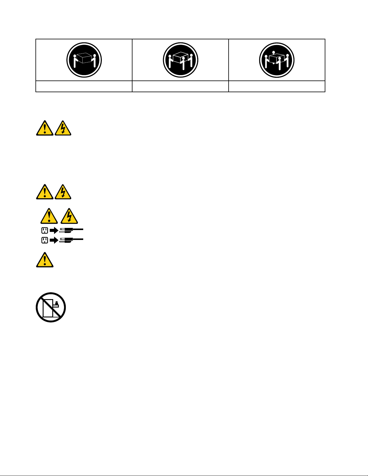
≥18 kg (37 lbs) ≥32 kg (70.5 lbs) ≥55 kg (121.2 lbs)
1
2
CAUTION:
Use safe practices when lifting.
CAUTION:
The power control button on the device and the power switch on the power supply do not turn off the
electrical current supplied to the device. The device also might have more than one power cord. To
remove all electrical current from the device, ensure that all power cords are disconnected from the
power source.
CAUTION:
Do not place any object weighing more than 82 kg (180 lbs.) on top of rack-mounted devices.
6 ideacentre A340 Hardware Maintenance Manual

Chapter 2. Environment and electrical input
Environment
• Air temperature:
Operating: From 10°C (50°F) to 35°C (95°F)
Storage in original shipping package: From -40°C (-40°F) to 60°C (140°F)
Storage without package: From -10°C (14°F) to 60°C (140°F)
• Humidity:
Operating: 20%–80% (non-condensing)
Storage: 20%–90% (non-condensing)
• Altitude:
Operating: From -15.2 m (-50 ft) to 3048 m (10 000 ft)
Storage: From -15.2 m (-50 ft) to 10 668 m (35 000 ft)
Electrical input
Input voltage: For PSU400W, 200 – 240 VAC; For PSU 450W/280W, 100 – 240 VAC
Input frequency: 50/60 Hz
© Copyright Lenovo 2019 7

8 ideacentre A340 Hardware Maintenance Manual

Chapter 3. General Checkout
Attention: The drives in the computer you are servicing might have been rearranged or the drive startup
sequence may have been changed. Be extremely careful during write operations such as copying, saving, or
formatting. Data or programs can be overwritten if you select an incorrect drive.
General error messages appear if a problem or conflict is found by an application, the operating system, or
both. For an explanation of these messages, refer to the information supplied with that software package.
Use the following procedure to help determine the cause of the problem:
1. Power-off the computer and all external devices.
2. Check all cables and power cords.
3. Set all display controls to the middle position.
4. Power-on all external devices.
5. Power-on the computer.
• Look for error codes displayed.
• Look for readable instructions or a main menu on the display.
If you did not receive the correct response, proceed to step 6.
If you did receive the correct response, proceed to step 7.
6. If one of the following happens, follow the instruction given:
• If the computer displays a POST error, go to “POST error codes”.
• If the computer hangs and no error is displayed, continue at step 7.
7. If the test stops and you cannot continue, replace the last device tested.
© Copyright Lenovo 2019 9

10 ideacentre A340 Hardware Maintenance Manual

Chapter 4. Using the Setup Utility program
The Setup Utility program is used to view and change the configuration settings of your computer. This
section provides information about only the major configuration settings available in the program.
Note: The operating system settings might override some similar settings in the Setup Utility program.
Starting the Setup Utility program
To start the Setup Utility program, do the following:
1. Turn on or restart your computer.
2. Before Windows
opens. If a BIOS password has been set, the Setup Utility program will not open until you enter the
correct password. For more information, see “Using BIOS passwords” on page 11.
Note: For some keyboards, you might need to press Fn+F1 to open the Setup Utility program.
To view and change the configuration settings, follow the instructions on the right side of the screen. The
keys used to perform various tasks are displayed at the bottom of the screen.
Enabling or disabling a device
This section provides information about how to enable or disable user access to hardware devices (such as
USB connectors or storage drives).
®
starts up, repeatedly press and release the F1 key until the Setup Utility program
To enable or disable a device, do the following:
1. Start the Setup Utility program. See “Starting the Setup Utility program” on page 11.
2. Select Devices.
3. Select the device you want to enable or disable and press Enter.
4. Select the desired setting and press Enter.
5. Exit the Setup Utility program. See “Exiting the Setup Utility program” on page 13.
Enabling or disabling the Automatic Power On features
If you enable the Automatic Power On features, your computer will start up automatically.
To enable or disable the Automatic Power On features, do the following:
1. Start the Setup Utility program. See “Starting the Setup Utility program” on page 11.
2. Select Power ➙ Automatic Power On and press Enter.
3. Select the feature you want to enable or disable and press Enter.
4. Select the desired setting and press Enter.
5. Exit the Setup Utility program. See “Exiting the Setup Utility program” on page 13.
Using BIOS passwords
By using the Setup Utility program, you can set passwords to prevent unauthorized access to your computer
and data.
© Copyright Lenovo 2019 11

You do not have to set all passwords to use your computer. However, using passwords improves computer
security.
Setup Utility program password types
The following types of passwords are available:
• Power-on password
When a power-on password is set, you are prompted to enter a valid password each time the computer is
turned on. The computer cannot be used until the valid password is entered.
• Administrator password
Setting an administrator password deters unauthorized users from changing configuration settings. If you
are responsible for maintaining the configuration settings of several computers, you might want to set an
administrator password.
When an administrator password is set, you are prompted to enter a valid password each time you try to
access the Setup Utility program. The Setup Utility program cannot be accessed until a valid password is
entered.
If both the power-on password and administrator password are set, you can enter either password.
However, you must use your administrator password to change all configuration settings.
Password considerations
A password can be any combination of up to 64 alphabetic and numeric characters. For security reasons, it
is recommended to use a strong password that cannot be easily compromised.
Note: The Setup Utility program passwords are not case sensitive.
To set a strong password, consider the following guidelines:
• Have at least eight characters in length
• Contain at least one alphabetic character and one numeric character
• Not be your name or your user name
• Not be a common word or a common name
• Be significantly different from your previous passwords
Setting, changing, and deleting a password
To set, change, or delete a password, do the following:
1. Start the Setup Utility program. See “Starting the Setup Utility program” on page 11.
2. Select Security.
3. Depending on the password type, select Set Power-On Password or Set Administrator Password,
and press Enter.
4. Follow the instructions on the right side of the screen to set, change, or delete a password.
Note: A password can be any combination of up to 64 alphabetic and numeric characters. For more
information, see “Password considerations” on page 12.
5. Exit the Setup Utility program. See “Exiting the Setup Utility program” on page 13.
Selecting a startup device
If your computer does not start up from a device as expected, you can choose to change the startup device
sequence permanently or select a temporary startup device.
12
ideacentre A340 Hardware Maintenance Manual

Changing the startup device sequence permanently
To change the startup device sequence permanently, do the following:
1. Depending on the type of the storage device, do one of the following:
• If the storage device is internal, go to step 2.
• If the storage device is a disc, ensure that your computer is on or turn on the computer. Then, insert
the disc into the optical drive.
• If the storage device is an external device other than a disc, connect the storage device to the
computer.
2. Start the Setup Utility program. See “Starting the Setup Utility program” on page 11.
3. Select Startup.
4. Follow the instructions on the right side of the screen to change the startup device sequence.
5. Exit the Setup Utility program. See “Exiting the Setup Utility program” on page 13.
Selecting a temporary startup device
Note: Not all discs and storage drives are bootable.
To select a temporary startup device, do the following:
1. Depending on the type of the storage device, do one of the following:
• If the storage device is internal, go to step 2.
• If the storage device is a disc, ensure that your computer is on or turn on the computer. Then, insert
the disc into the optical drive.
• If the storage device is an external device other than a disc, connect the storage device to the
computer.
2. Turn on or restart the computer. Before Windows starts up, repeatedly press and release the F12 key
until Startup Device Menu is displayed.
Note: For some keyboards, you might need to press Fn+F12 to display Startup Device Menu.
3. Select the desired storage device and press Enter. The computer will start up from the device you select.
If you want to select a permanent startup device, select Enter Setup on Startup Device Menu and press
Enter to start the Setup Utility program. For more information about how to select a permanent startup
device, see “Changing the startup device sequence permanently” on page 13.
Exiting the Setup Utility program
To exit the Setup Utility program, do one of the following:
• If you want to save the new settings, press the F10 key. Then, select Yes in the window displayed and
press Enter.
Note: For some keyboards, you might need to press Fn+F10 to exit the Setup Utility program.
• If you do not want to save the new settings, select Exit ➙ Discard Changes and Exit and press Enter.
Then, select Yes in the window displayed and press Enter.
Chapter 4. Using the Setup Utility program 13

14 ideacentre A340 Hardware Maintenance Manual

Chapter 5. Symptom-to-FRU Index
The Symptom-to-FRU index lists error symptoms and possible causes. The most likely cause is listed first.
Always begin with Chapter 4, “General Checkout,” on page 11. This index can also be used to help you
decide which FRUs to have available when servicing a computer. If you are unable to correct the problem
using this index, go to “Undetermined problems” on page 20.
Notes:
• If you have both an error message and an incorrect audio response, diagnose the error message first.
• If you cannot run the diagnostic tests or you get a diagnostic error code when running a test but did
receive a POST error message, diagnose the POST error message first.
• If you did not receive any error messages, look for a description of your error symptom in the first part of
this index.
Hard disk drive boot error
A hard disk drive boot error can be caused by the following.
Error FRU/Action
The startup drive is not included in the boot sequence
configuration.
No operating system is installed on the boot drive. Install an operating system on the boot drive.
Check the configuration and ensure the startup drive is in
the boot sequence.
The boot sector on the startup drive is corrupted. The drive must be formatted. Do the following:
1. Attempt to back up the data on the failing hard disk
drive.
2. Use the operating system to format the hard disk
drive.
The drive is defective. Replace the hard disk drive.
Power Supply Problems
Follow these procedures if you suspect there is a power supply problem.
Check/Verify FRU/Action
Check that the following are properly installed:
• Power Cord
• On/Off Switch connector
• System Board Power Supply connectors
• Microprocessor connections
Check the power cord. Power Cord
Check the power-on switch. Power-on Switch
Reseat connectors
© Copyright Lenovo 2019 15

POST error codes
Each time you turn the computer on, it performs a series of tests to check that the system is operating
correctly and that certain options are set. This series of tests is called the Power-On Self-Test, or POST.
POST does the following:
• Checks some basic motherboard operations
• Checks that the memory is working correctly
• Starts video operations
• Verifies that the boot drive is working
POST Error Message Description/Action
Keyboard error
Reboot and Select proper Boot device or Insert Boot
Media in selected Boot device
Cannot initialize the keyboard. Make sure the keyboard is
properly connected to the computer and that no keys are
held pressed during POST. To purposely configure the
computer without a keyboard, select Keyboardless
operation in Startup and set the option to Enabled. The
BIOS then ignores the missing keyboard during POST.
The BIOS was unable to find a suitable boot device. Make
sure the boot drive is properly connected to the
computer. Make sure you have bootable media in the
boot device.
Undetermined problems
1. Power-off the computer.
2. Remove or disconnect the following components (if connected or installed) one at a time.
a. External devices (modem, printer, or mouse)
b. Extended video memory
c. External Cache
d. External Cache RAM
e. Hard disk drive
f. Disk drive
3. Power-on the computer to re-test the system.
4. Repeat steps 1 through 3 until you find the failing device or component.
If all devices and components have been removed and the problem continues, replace the system board.
16
ideacentre A340 Hardware Maintenance Manual

Chapter 6. Hardware locations
1
2
3 4 5
77
6
This section provides information about the locations of your computer hardware.
Note: The computer hardware might look slightly different from the illustrations.
Overview
Attention: Be careful not to block any air vents on the computer. Blocked air vents can cause overheating.
Figure 1. Front view
1 Air vents
3 Camera indicator 4 Camera (standard or Windows Hello compatible)
5 Microphone
7 Wireless antennas
© Copyright Lenovo 2019 17
2 Camera cover slider
6 Screen

1 2 3 4 5
Figure 2. Rear view
1
2
3
4
5
6
1 Power connector 2 Ethernet connector
3 HDMI-out connector
5 USB 3.1 connector
Figure 3. Left view and right view
18 ideacentre A340 Hardware Maintenance Manual
4 USB 2.0 connectors

1 USB 3.1 connector
3 Combo audio jack 4 Optical drive (for select models)
5 Power button (with indicator) 6 Speakers
2 Memory card slot
Chapter 6. Hardware locations 19

Major FRUs and CRUs
Note: Depending on your computer model, some of the following components might not be available.
20
ideacentre A340 Hardware Maintenance Manual

x
a
b
c
d
e
h
g
f
i
j
k
l
m
o
n
p
u
v
t
s
q
r
w
y
Figure 4. Major FRUs and CRUs
Chapter 6. Hardware locations 21
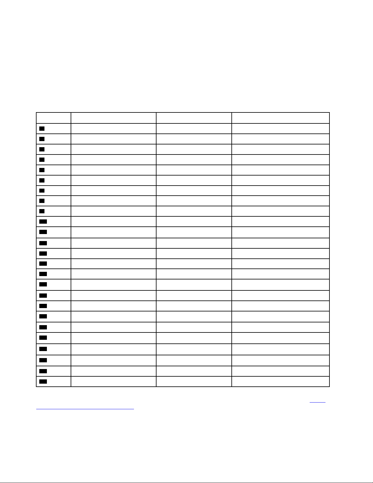
The following table lists the major FRUs shown in the illustration above and identifies which FRUs are also
self-service CRUs or optional-service CRUs.
Notes:
• Self-service CRUs: Parts to be installed or replaced by customer themselves.
• Optional-service CRUs: Parts can be installed or replaced by customers or technicians under certain
terms of the applicable warranty service type for your country or region.
• Non-CRUs: Parts must be installed or replaced only by trained service technicians
No. Description Self-service CRU Optional-service CRU
1
2
3
4
5
6
7
8
9
10
11
12
13
14
15
16
17
18
19
Stand base bracket
Stand base
Yes No
Yes No
Rear cover Yes No
Middle frame No No
Fan No No
Wi-Fi card No No
Wi-Fi card cover No No
Hard disk drive cable No No
Hard disk drive No Yes
Mount bracket No No
Optical drive No No
Camera module
Camera cable
No No
No No
Power switch board No No
Power switch cable No No
System board frame No No
Heat sink No No
M.2 solid-state drive No No
Coin-cell battery
No No
20
21
22
23
24
25
CPU
System board
Optical drive
Speakers Yes No
Wi-Fi antennas No No
Panel module No No
No No
No No
No No
For detailed FRU information, such as the FRU part numbers and supported computer models, go to: http://
www.lenovo.com/serviceparts-lookup
22 ideacentre A340 Hardware Maintenance Manual

Parts on the system boards
Figure 5. Parts on the system board (A340-22IBC/24IBC)
1 CAMERA & Mic 2 Mic Connector
3 USB 3.1 Gen 2 connector 4 Card reader
5 Audio jack
7 Fan connector 8 Touch connector
9 USB 2.0 connectors
11 RJ45 connector
13 Power board connector
15 HDD FFC connector 16 ODD FFC connector
17 Converter connector
6 Speaker connector
10 HDMI-out connector
12 DC IN connector
14 LVDS FFC connector
Chapter 6. Hardware locations 23

Figure 6. Parts on the system board (A340-22IWL/24IWL)
1 CAMERA & Mic 2 USB 2.0 / USB 3.0 connector
3 USB 3.1 Gen 2 connector 4 Card reader
5 Audio jack
7 Fan connector 8 Touch connector
9 USB 2.0 connectors
11 RJ45 connector
13 HDMI-in connector 14 Power board connector
15 LVDS FFC connector 16 HDD FFC connector
17 ODD FFC connector 18 Converter connector
6 Speaker connector
10 HDMI-out connector
12 DC IN connector
Figure 7. Parts on the system board (A340-22IGM/24IGM)
24 ideacentre A340 Hardware Maintenance Manual

1 Camera connector 2 Mic Connector
3 USB 3.1 connector 4 Card reader
5 Audio jack
7 Fan connector 8 Touch connector
9 USB 2.0 connectors
11 RJ45 connector
13 Power board connector
15 HDD FFC connector 16 ODD FFC connector
17 Converter connector
6 Speaker connector
10 HDMI-out connector
12 DC IN connector
14 LVDS FFC connector
1 Camera connector 2 Mic Connector
3 USB 3.1 Gen 1 connector 4 Card reader
5 Audio jack
7 Fan connector 8 Touch connector
9 USB 2.0 connectors
11 RJ45 connector
13 Power board connector
15 HDD FFC connector 16 ODD FFC connector
17 Converter connector
6 Speaker connector
10 HDMI-out connector
12 DC IN connector
14 LVDS FFC connector
Figure 8. Parts on the system board (A340-22AST)
Chapter 6. Hardware locations 25

26 ideacentre A340 Hardware Maintenance Manual

Chapter 7. Installing or replacing hardware
This chapter contains the following topics:
• “Handling static-sensitive devices” on page 27
• “Installing or replacing hardware” on page 27
Handling static-sensitive devices
Do not open the static-protective package containing the new part until the defective part has been removed
and you are ready to install the new part. Static electricity, although harmless to you, can seriously damage
computer components and parts.
When you handle parts and other computer components, take these precautions to avoid static-electricity
damage:
• Limit your movement. Movement can cause static electricity to build up around you.
• Always handle parts and other computer components carefully. Handle PCI/PCI-Express cards, memory
modules, system boards, and microprocessors by the edges. Never touch any exposed circuitry.
• Prevent others from touching the parts and other computer components.
• Touch the static-protective package containing the part to a metal expansion-slot cover or other
unpainted metal surface on the computer for at least two seconds. This reduces static electricity from the
package and your body before you install or replace a new part.
• When possible, remove the new part from the static-protective package, and install it directly in the
computer without setting the part down. When this is not possible, place the static-protective package
that the part came in on a smooth, level surface and place the part on the package.
• Do not place the part on the computer cover or other metal surface.
Installing or replacing hardware
This section provides instructions on how to install or replace hardware for your computer. You can expand
the capabilities of your computer and maintain your computer by installing or replacing hardware.
Attention: Do not open your computer or attempt any repair before reading and understanding the Chapter
1 “Read this first: Important safety information” on page 1.
Notes:
• Some of the hardware parts in this section are optional.
• Use computer parts provided only by Lenovo.
• When installing or replacing an option, use the appropriate instructions in this section along with the
instructions that come with the option.
• In most areas of the world, Lenovo requires the return of the defective CRU. Information about this will
come with the CRU or will come a few days after the CRU arrives.
Removing the computer stand base
Attention: Do not open your computer or attempt any repair before reading and understanding the Chapter
1 “Read this first: Important safety information” on page 1.
• Turn off the computer and wait 3 to 5 minutes to let it cool down before removing the cover.
© Copyright Lenovo 2019 27

• It is helpful to lay the computer on a flat, stable and wide surface.
• Make sure the surface is clean and dry.
To remove the computer stand base, do the following:
1. Turn off all connected devices and the computer. Then, disconnect all power cords from electrical
outlets and all cables that are connected to the computer.
2. Gently lay the computer down on its panel. Let the base naturally be supported by the flat surface.
3. Remove the stand base bracket
1 .
Figure 9. Removing the bracket
4. Remove 4 screws 2 .
Figure 10. Removing 4 screws
5. Remove the stand base 3 .
28
ideacentre A340 Hardware Maintenance Manual
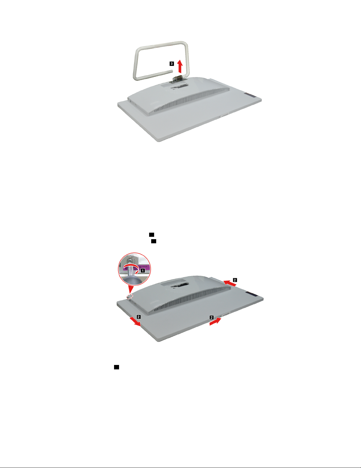
Figure 11. Removing the stand base
Removing the rear cover
Attention: Do not open your computer or attempt any repair before reading and understanding the Chapter
1 “Read this first: Important safety information” on page 1.
Make sure the following FRUs (or CRUs) have been removed.
“Removing the computer stand base” on page 27
To remove the rear cover, do the following:
1. Twist the hand screw ring clockwise
the rear cover from the panel module
1 until the rear cover is loosened. Then insert a pry tool to separate
2 .
Figure 12. Separating the rear cover from the panel module
2. Remove the rear cover 3 .
Chapter 7. Installing or replacing hardware 29

Figure 13. Removing the rear cover
Replacing the speakers
Attention: Do not open your computer or attempt any repair before reading and understanding the Chapter
1 “Read this first: Important safety information” on page 1.
Make sure the following FRUs (or CRUs) have been removed.
“Removing the computer stand base” on page 27
“Removing the rear cover” on page 29
To remove the speakers, do the following:
Detach the speakers connector
Figure 14. Removing the speakers
What to do next:
• To work with another piece of hardware, go to the appropriate section.
• To complete the installation or replacement, go to “Completing the parts replacement” on page 48.
1 . Then remove the speakers 2 .
Replacing the hard disk drive
Attention: Do not open your computer or attempt any repair before reading and understanding the Chapter
1 “Read this first: Important safety information” on page 1.
Make sure the following FRUs (or CRUs) have been removed.
30
ideacentre A340 Hardware Maintenance Manual

“Removing the computer stand base” on page 27
“Removing the rear cover” on page 29
“Replacing the speakers” on page 30
To remove the hard disk drive, do the following:
Lift up the hard disk drive from the bracket
Figure 15. Removing the hard disk drive
1 . Then unplug the hard disk drive 2 .
What to do next:
• To work with another piece of hardware, go to the appropriate section.
• To complete the installation or replacement, go to “Completing the parts replacement” on page 48.
Replacing the optical drive
Attention: Do not open your computer or attempt any repair before reading and understanding the Chapter
1 “Read this first: Important safety information” on page 1.
Make sure the following FRUs (or CRUs) have been removed.
“Removing the computer stand base” on page 27
“Removing the rear cover” on page 29
“Replacing the speakers” on page 30
To remove the optical drive, do the following:
Remove 1 screw
1 that secures the optical drive to the bracket. Then pull out the optical drive 2 .
Chapter 7. Installing or replacing hardware 31

Figure 16. Removing 1 screw and pulling out the optical drive
What to do next:
• To work with another piece of hardware, go to the appropriate section.
• To complete the installation or replacement, go to “Completing the parts replacement” on page 48.
Replacing the middle frame
Attention: Do not open your computer or attempt any repair before reading and understanding the Chapter
1 “Read this first: Important safety information” on page 1.
Make sure the following FRUs (or CRUs) have been removed.
“Removing the computer stand base” on page 27
“Removing the rear cover” on page 29
“Replacing the speakers” on page 30
To remove the middle frame, do the following:
Remove 4 screws
2 .
Figure 17. Removing screws and the middle frame
1 that secure the middle frame to the system board frame. Then remove the middle frame
What to do next:
• To work with another piece of hardware, go to the appropriate section.
32
ideacentre A340 Hardware Maintenance Manual
• To complete the installation or replacement, go to “Completing the parts replacement” on page 48.
Replacing the fan
Attention: Do not open your computer or attempt any repair before reading and understanding the Chapter
1 “Read this first: Important safety information” on page 1.
Make sure the following FRUs (or CRUs) have been removed.
“Removing the computer stand base” on page 27
“Removing the rear cover” on page 29
“Replacing the speakers” on page 30
“Replacing the middle frame” on page 32
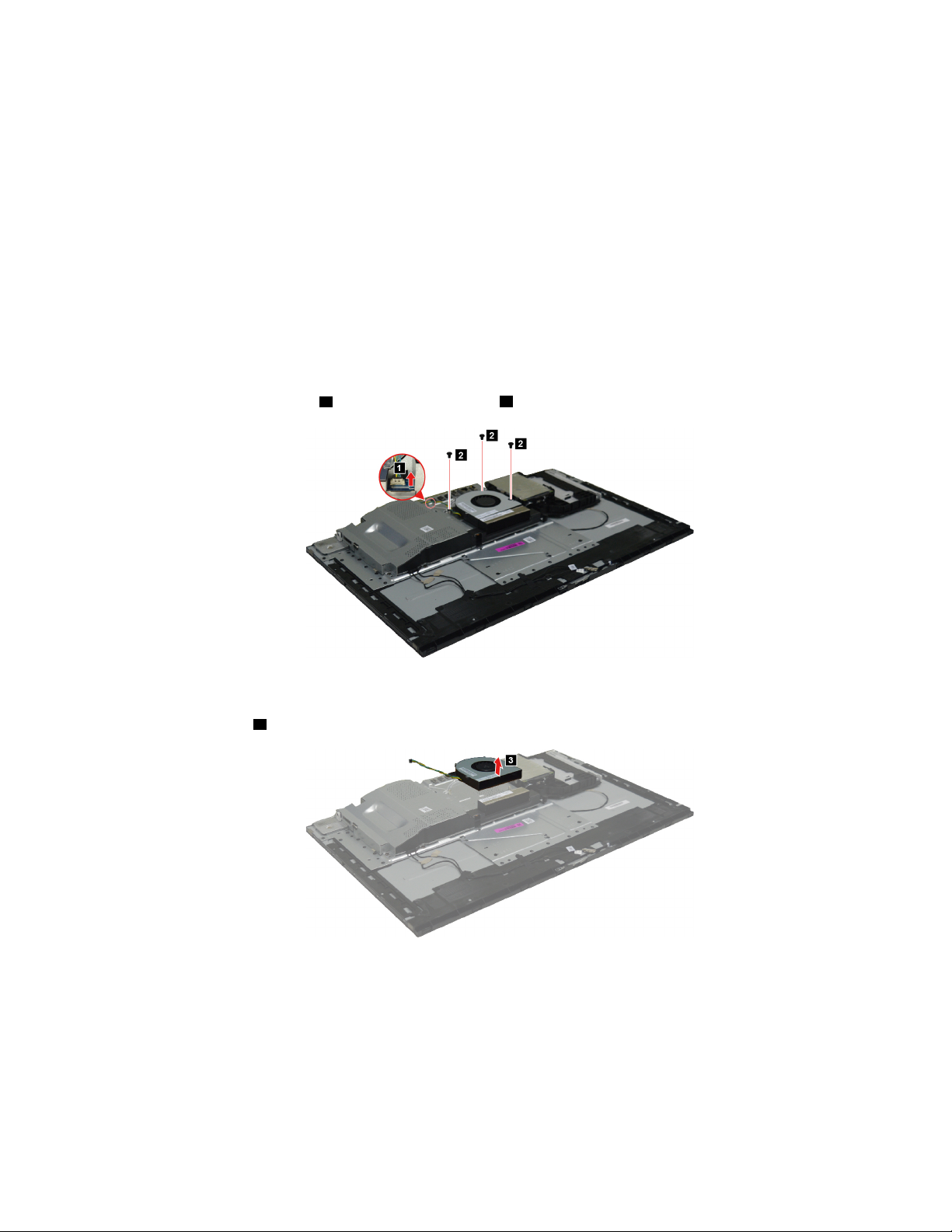
To remove the fan, do the following:
1. Detach the fan connector
1 . Then remove 3 screws 2 that secure the fan to the system board frame.
Figure 18. Removing the fan connector and screws
2. Remove the fan 3 .
Figure 19. Removing the fan
What to do next:
• To work with another piece of hardware, go to the appropriate section.
• To complete the installation or replacement, go to “Completing the parts replacement” on page 48.
Chapter 7. Installing or replacing hardware 33

Replacing the system board frame
Attention: Do not open your computer or attempt any repair before reading and understanding the Chapter
1 “Read this first: Important safety information” on page 1.
Make sure the following FRUs (or CRUs) have been removed.
“Removing the computer stand base” on page 27
“Removing the rear cover” on page 29
“Replacing the speakers” on page 30
“Replacing the middle frame” on page 32
“Replacing the fan” on page 33
To remove the system board frame, do the following:
Remove 3 screws
board frame
Figure 20. Removing screws and the system board frame
What to do next:
• To work with another piece of hardware, go to the appropriate section.
• To complete the installation or replacement, go to “Completing the parts replacement” on page 48.
1 that secure the system board frame to the system board. Then remove the system
2 .
Replacing the hard disk drive cable
Attention: Do not open your computer or attempt any repair before reading and understanding the Chapter
1 “Read this first: Important safety information” on page 1.
Make sure the following FRUs (or CRUs) have been removed.
“Removing the computer stand base” on page 27
“Removing the rear cover” on page 29
“Replacing the speakers” on page 30
“Replacing the hard disk drive” on page 30
“Replacing the middle frame” on page 32
“Replacing the system board frame” on page 34
To remove the camera module, do the following:
34
ideacentre A340 Hardware Maintenance Manual
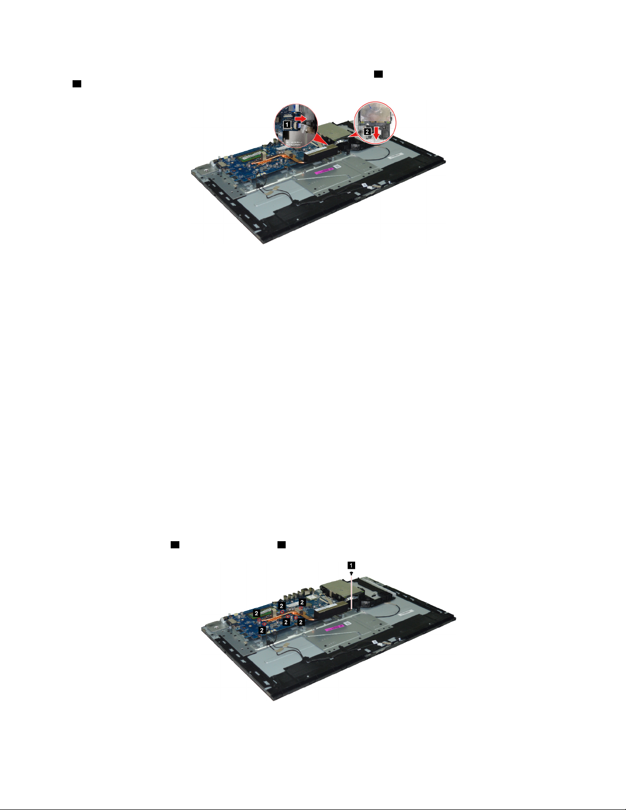
Detach the hard disk drive cable connector from the system board 1 . Then unplug the hard disk drive cable
2 .
Figure 21. Removing screws and camera module
What to do next:
• To work with another piece of hardware, go to the appropriate section.
• To complete the installation or replacement, go to “Completing the parts replacement” on page 48.
Replacing the heat sinks
Attention: Do not open your computer or attempt any repair before reading and understanding the Chapter
1 “Read this first: Important safety information” on page 1.
Make sure the following FRUs (or CRUs) have been removed.
“Removing the computer stand base” on page 27
“Removing the rear cover” on page 29
“Replacing the speakers” on page 30
“Replacing the middle frame” on page 32
“Replacing the fan” on page 33
“Replacing the system board frame” on page 34
To remove the heat sinks, do the following:
1. Remove 1 screw
1 and loosen 6 screws 2 .
Figure 22. Removing 1 screw and loosening 6 screws
Chapter 7. Installing or replacing hardware 35
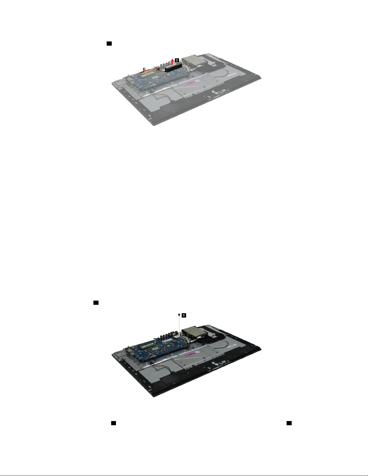
2. Remove the heat sink 3 .
Figure 23. Removing the heat sink
What to do next:
• To work with another piece of hardware, go to the appropriate section.
• To complete the installation or replacement, go to “Completing the parts replacement” on page 48.
Replacing the Wi-Fi card
Attention: Do not open your computer or attempt any repair before reading and understanding the Chapter
1 “Read this first: Important safety information” on page 1.
Make sure the following FRUs (or CRUs) have been removed.
“Removing the computer stand base” on page 27
“Removing the rear cover” on page 29
“Replacing the speakers” on page 30
“Replacing the middle frame” on page 32
“Replacing the fan” on page 33
“Replacing the system board frame” on page 34
To remove the Wi-Fi card, do the following:
1. Remove 1 screw
1 that secures the Wi-Fi card to the system board.
Figure 24. Removing 1 screw
2. Remove the card cover 2 . Then detach the Wi-Fi antenna connectors from the Wi-Fi card 3 .
36
ideacentre A340 Hardware Maintenance Manual

Figure 25. Removing the cover and detaching the antenna connectors
3. Remove the Wi-Fi card 4 .
Figure 26. Removing the Wi-Fi card
What to do next:
• To work with another piece of hardware, go to the appropriate section.
• To complete the installation or replacement, go to “Completing the parts replacement” on page 48.
Replacing the antennas
Attention: Do not open your computer or attempt any repair before reading and understanding the Chapter
1 “Read this first: Important safety information” on page 1.
Make sure the following FRUs (or CRUs) have been removed.
“Removing the computer stand base” on page 27
“Removing the rear cover” on page 29
“Replacing the speakers” on page 30
“Replacing the hard disk drive” on page 30
“Replacing the middle frame” on page 32
“Replacing the system board frame” on page 34
“Replacing the Wi-Fi card” on page 36
Chapter 7. Installing or replacing hardware 37

To remove the camera module, do the following:
Lift up the main and auxiliary antennas
remove the antennas
Figure 27. Removing screws and camera module
2 .
1 . Release the antenna cables from the cable guides and then
What to do next:
• To work with another piece of hardware, go to the appropriate section.
• To complete the installation or replacement, go to “Completing the parts replacement” on page 48.
Replacing the memory module
Attention: Do not open your computer or attempt any repair before reading and understanding the Chapter
1 “Read this first: Important safety information” on page 1.
Make sure the following FRUs (or CRUs) have been removed.
“Removing the computer stand base” on page 27
“Removing the rear cover” on page 29
“Replacing the speakers” on page 30
“Replacing the middle frame” on page 32
“Replacing the fan” on page 33
“Replacing the system board frame” on page 34
To remove the memory module, do the following:
Release the two latches on both edges of the socket at the same time
2 .
1 . Then remove the memory module
38
ideacentre A340 Hardware Maintenance Manual
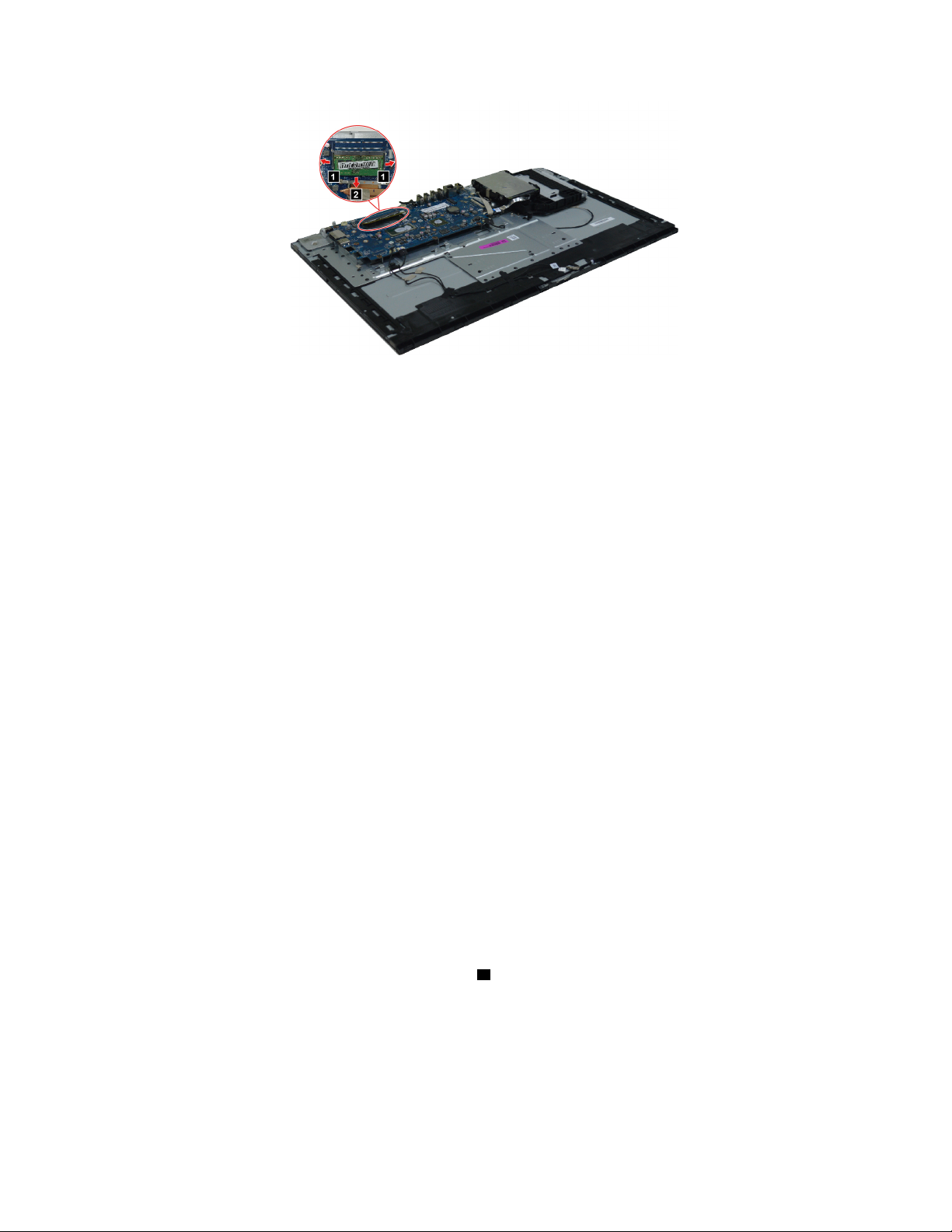
Figure 28. Removing the memory module
What to do next:
• To work with another piece of hardware, go to the appropriate section.
• To complete the installation or replacement, go to “Completing the parts replacement” on page 48.
Replacing the coin-cell battery
Attention: Do not open your computer or attempt any repair before reading and understanding the Chapter
1 “Read this first: Important safety information” on page 1.
Your computer has a special type of memory that maintains the date, time, and settings for built-in features,
such as parallel-connector assignments (configuration). A coin-cell battery keeps this information active
when you turn off the computer.
The coin-cell battery normally requires no charging or maintenance throughout its life; however, no coin-cell
battery lasts forever. If the coin-cell battery fails, the date, time, and configuration information (including
passwords) are lost. An error message is displayed when you turn on the computer.
Make sure the following FRUs (or CRUs) have been removed.
“Removing the computer stand base” on page 27
“Removing the rear cover” on page 29
“Replacing the speakers” on page 30
“Replacing the middle frame” on page 32
“Replacing the fan” on page 33
“Replacing the system board frame” on page 34
To remove the coin-cell battery, do the following:
Use a pry tool to push and lift up the coin-cell battery
1 .
Chapter 7. Installing or replacing hardware 39

Figure 29. Removing the coin-cell battery
What to do next:
• To work with another piece of hardware, go to the appropriate section.
• To complete the installation or replacement, go to “Completing the parts replacement” on page 48.
Notes:
– When the computer is turned on for the first time after replacing the coin-cell battery, an error message
might be displayed. This is normal after replacing the coin-cell battery.
– Use the Setup Utility program to set the date, time, and any passwords. See Chapter 4 “Using the
Setup Utility program” on page 11.
Replacing the M.2 solid-state drive
Attention: Do not open your computer or attempt any repair before reading and understanding the Chapter
1 “Read this first: Important safety information” on page 1.
Make sure the following FRUs (or CRUs) have been removed.
“Removing the computer stand base” on page 27
“Removing the rear cover” on page 29
“Replacing the speakers” on page 30
“Replacing the middle frame” on page 32
“Replacing the fan” on page 33
“Replacing the system board frame” on page 34
To remove the M.2 solid-state drive, do the following:
1. Remove 1 screw
40
ideacentre A340 Hardware Maintenance Manual
1 that secures the M.2 solid-state drive to the system board.
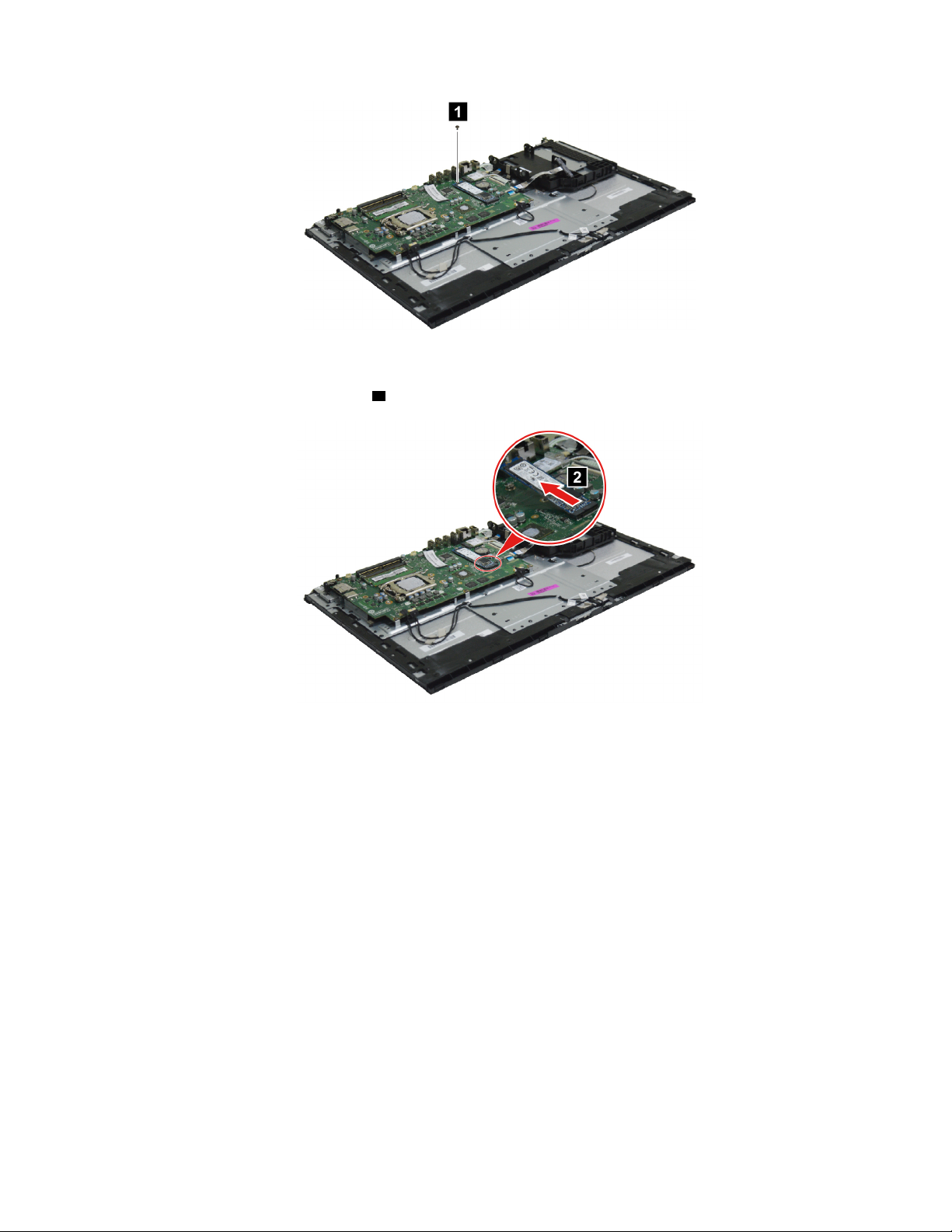
Figure 30. Removing 1 screw
2. Remove the M.2 solid-state drive 2 .
Figure 31. Removing the M.2 solid-state drive
What to do next:
• To work with another piece of hardware, go to the appropriate section.
• To complete the installation or replacement, go to “Completing the parts replacement” on page 48.
Replacing the microprocessor (for selected models)
Attention: Do not open your computer or attempt any repair before reading and understanding the Chapter
1 “Read this first: Important safety information” on page 1.
Make sure the following FRUs (or CRUs) have been removed.
“Removing the computer stand base” on page 27
“Removing the rear cover” on page 29
“Replacing the speakers” on page 30
“Replacing the middle frame” on page 32
“Replacing the fan” on page 33
“Replacing the system board frame” on page 34
Chapter 7. Installing or replacing hardware 41

“Replacing the heat sinks” on page 35
To remove the microprocessor, do the following:
Lift the small handle and open the retainer in the directions shown as
microprocessor out of the socket
Figure 32. Removing the microprocessor
3 .
1 and 2 . Then remove the
Notes:
• Your microprocessor and socket might look different from the one illustrated.
• Touch only the edges of the microprocessor. Do not touch the gold contacts on the bottom.
• Do not touch the thermal grease while handling the microprocessor.
• Do not drop anything onto the microprocessor socket while it is exposed. The socket pins must be kept
as clean as possible.
What to do next:
• To work with another piece of hardware, go to the appropriate section.
• To complete the installation or replacement, go to “Completing the parts replacement” on page 48.
Replacing the system board
Attention: Do not open your computer or attempt any repair before reading and understanding the Chapter
1 “Read this first: Important safety information” on page 1.
Make sure the following FRUs (or CRUs) have been removed.
“Removing the computer stand base” on page 27
“Removing the rear cover” on page 29
“Replacing the speakers” on page 30
“Replacing the middle frame” on page 32
“Replacing the fan” on page 33
“Replacing the system board frame” on page 34
“Replacing the heat sinks” on page 35
“Replacing the Wi-Fi card” on page 36
“Replacing the memory module” on page 38
“Replacing the coin-cell battery” on page 39
“Replacing the M.2 solid-state drive” on page 40
42
ideacentre A340 Hardware Maintenance Manual

“Replacing the microprocessor (for selected models)” on page 41
To remove the system board, do the following:
1. Detach 7 connectors from the system board
1 .
Figure 33. Detaching 7 connectors
2. Remove 7 screws 2 that secure the system board to the panel module.
Figure 34. Removing the system board
3. Remove the system board 3 .
Chapter 7. Installing or replacing hardware 43
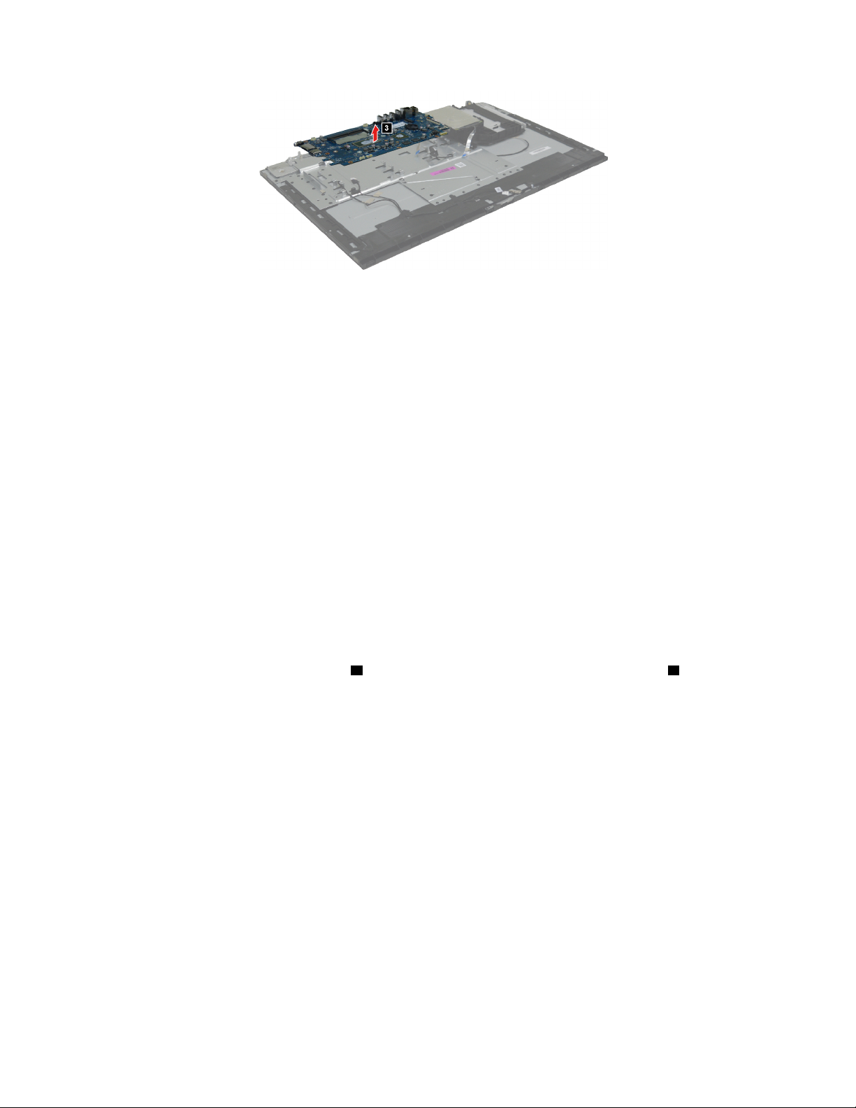
Figure 35. Removing the system board
What to do next:
• To work with another piece of hardware, go to the appropriate section.
• To complete the installation or replacement, go to “Completing the parts replacement” on page 48.
Replacing the power switch board
Attention: Do not open your computer or attempt any repair before reading and understanding the Chapter
1 “Read this first: Important safety information” on page 1.
Make sure the following FRUs (or CRUs) have been removed.
“Removing the computer stand base” on page 27
“Removing the rear cover” on page 29
“Replacing the speakers” on page 30
“Replacing the middle frame” on page 32
“Replacing the system board frame” on page 34
To remove the power switch board, do the following:
Detach the power switch cable connectors
44
ideacentre A340 Hardware Maintenance Manual
1 . Then remove the power switch board and cable 2 .

Figure 36. Detaching the power switch cable connectors
What to do next:
• To work with another piece of hardware, go to the appropriate section.
• To complete the installation or replacement, go to “Completing the parts replacement” on page 48.
Replacing the camera module
Attention: Do not open your computer or attempt any repair before reading and understanding the Chapter
1 “Read this first: Important safety information” on page 1.
Make sure the following FRUs (or CRUs) have been removed.
“Removing the computer stand base” on page 27
“Removing the rear cover” on page 29
“Replacing the speakers” on page 30
“Replacing the hard disk drive” on page 30
“Replacing the middle frame” on page 32
“Replacing the system board frame” on page 34
To remove the camera module, do the following:
1. Remove 3 screws
module
2 .
1 that secure the camera module to the display module. Then lift up the camera
Chapter 7. Installing or replacing hardware 45

Figure 37. Removing screws and camera module
2. Detach the 4 camera cable connectors from the camera module and system board 3 . Then remove the
camera module and camera cable.
Figure 38. Detaching the 4 camera cable connectors
What to do next:
• To work with another piece of hardware, go to the appropriate section.
• To complete the installation or replacement, go to “Completing the parts replacement” on page 48.
Replacing the mount bracket and optical drive cable
Attention: Do not open your computer or attempt any repair before reading and understanding the Chapter
1 “Read this first: Important safety information” on page 1.
Make sure the following FRUs (or CRUs) have been removed.
“Removing the computer stand base” on page 27
“Removing the rear cover” on page 29
“Replacing the speakers” on page 30
“Replacing the hard disk drive” on page 30
“Replacing the optical drive” on page 31
“Replacing the middle frame” on page 32
“Replacing the fan” on page 33
46
ideacentre A340 Hardware Maintenance Manual
“Replacing the system board frame” on page 34
To remove the mount bracket and optical drive cable, do the following:
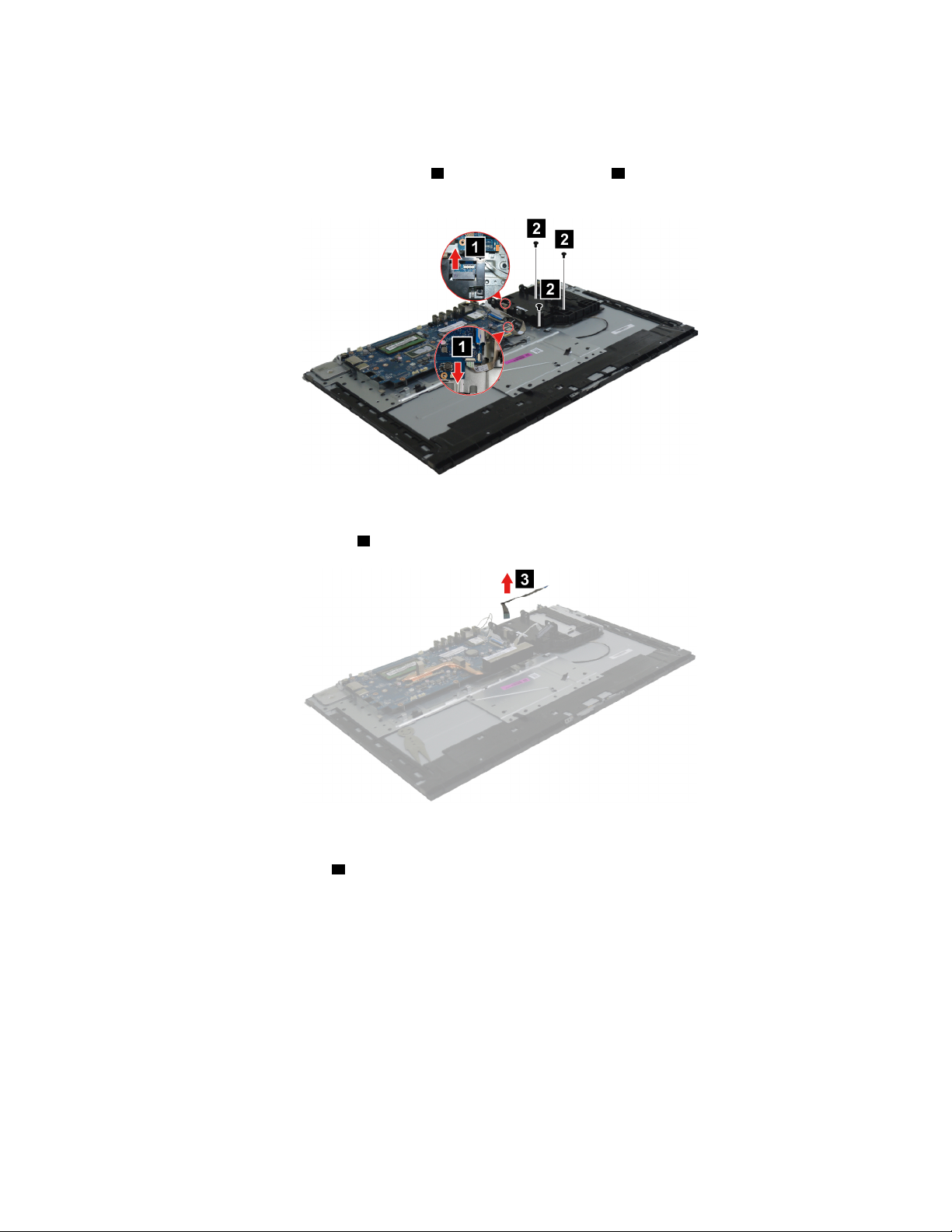
1. Detach the optical drive cable connectors
1 . Then remove 3 screws 2 that secure the mount bracket to
the panel module.
Figure 39. Detaching optical drive cable connectors and removing screws
2. Remove the optical drive cable 3 .
Figure 40. Removing the optical drive cable
3. Remove the mount bracket 4 .
Chapter 7. Installing or replacing hardware 47

Figure 41. Removing the mount bracket
What to do next:
• To work with another piece of hardware, go to the appropriate section.
• To complete the installation or replacement, go to “Completing the parts replacement” on page 48.
Completing the parts replacement
To reinstall the computer covers and reconnect cables to your computer, do the following:
1. Ensure that all components have been reassembled correctly and that no tools or loose screws are left
inside your computer. See Chapter 6 “Hardware locations” on page 17 for the locations of various
components in your computer.
2. Ensure that the cables are routed correctly before reinstalling the computer cover. Keep cables clear of
the hinges and sides of the computer chassis to avoid interference with reinstalling the computer cover.
3. Reinstall the front bezel.
4. Reinstall the side cover.
5. If a locking device is available, use it to lock the computer.
6. Reconnect the external cables and power cords to the corresponding connectors on the computer.
7. Depending on the parts you installed or replaced, you might need to confirm the updated information.
See Chapter 4 “Using the Setup Utility program” on page 11.
8. If a newly installed hardware component does not work normally, update the device driver.
48
ideacentre A340 Hardware Maintenance Manual

Chapter 8. Additional Service Information
This chapter provides additional information that the service representative might find helpful.
Power management
Power management reduces the power consumption of certain components of the computer such as the
system power supply, processor, hard disk drives, and some monitors.
Advanced configuration and power interface (ACPI) BIOS
As this computer has an ACPI BIOS system, the operating system is allowed to control the power
management features of the computer and the settings for Advanced Power Management (APM) BIOS mode
is ignored. Not all operating systems support ACPI BIOS mode.
Automatic Power-On features
The Automatic Power-On features within the Power Management menu allow you to enable and disable
features that turn on the computer automatically.
• Wake Up on Alarm: You can specify a date and time at which the computer will be turned on
automatically. This can be either a single event , a daily event or a weekly event.
• Wake Up on LAN: This feature allows LAN adapter card to wake the System.
© Copyright Lenovo 2019 49

50 ideacentre A340 Hardware Maintenance Manual

Trademarks
The following terms are trademarks of Lenovo in the United States, other countries, or both:
ideacentre
Lenovo
The Lenovo logo
Windows is a trademark of the Microsoft group of companies.
Other company, product, or service names may be trademarks or service marks of others.
© Copyright Lenovo 2019 1
 Loading...