

Page 1

ThinkStation
HardwareInstallationandReplacementGuide
MachineTypes:4155,4158,and4218
Page 2

Note:Beforeusingthisinformationandtheproductitsupports,besuretoreadandunderstandthe
ThinkStationSafetyandWarrantyGuideforthisproductandAppendixB“Notices”onpage53.
SecondEdition(September2011)
©CopyrightLenovo2009,2011.
LIMITEDANDRESTRICTEDRIGHTSNOTICE:IfdataorsoftwareisdeliveredpursuantaGeneralServicesAdministration
“GSA”contract,use,reproduction,ordisclosureissubjecttorestrictionssetforthinContractNo.GS-35F-05925.
Page 3

Contents
Figures................iii
Chapter1.Importantsafety
information...............1
Chapter2.Overview...........3
Additionalinformationresources........3
Handlingstatic-sensitivedevices........3
Locations..................4
Locatingcontrolsandconnectorsonthefront
ofyourcomputer.............4
Locatingconnectorsontherearofyour
computer................5
Locatingcomponents...........7
Identifyingpartsonthesystemboard.....8
Chapter3.Installingoptionsand
replacinghardware..........11
Installingexternaloptions..........11
Installinginternaloptions..........11
Removingthecomputercover.......11
Removingthefrontbezel.........12
Accessingsystemboardcomponents....13
Installinginternaldrives.........15
Replacingthebattery............22
Replacingthepowersupplyassembly.....23
Installingorreplacingamemorymodule....25
Installingorreplacingadaptercards......27
Installingadaptercards.........28
Replacingadaptercards.........30
Replacingtheheatsinkandfanassembly....31
Replacingaharddiskdrive..........33
Replacinganopticaldrive..........34
Replacingthediskettedriveorcardreader...35
Replacingthefrontpanelconnectorassembly..37
Replacingtheharddiskdrivefanassembly...38
Replacingtherearfanassembly........40
Replacingtheinternalspeaker........41
Replacingthekeyboard...........42
Replacingthemouse............42
Chapter4.Completingtheparts
replacement..............45
Obtainingdevicedrivers...........45
Chapter5.Securityfeatures.....47
Lockingdevices..............47
Passwordprotection............48
Erasingalostorforgottenpassword(clearing
CMOS)..................48
AppendixA.Systemmemoryspeed.49
AppendixB.Notices..........53
Televisionoutputnotice...........54
Trademarks................54
Index..................55
©CopyrightLenovo2009,2011
i
Page 4

iiThinkStationHardwareInstallationandReplacementGuide
Page 5

Figures
1.Frontconnectors............4
2.Rearconnectorlocations.........5
3.Componentlocations...........7
4.Systemboardpartslocations.......8
5.Removingthecomputercover......12
6.Removingthefrontbezel........13
7.Removingtheharddiskdrivefanduct...14
8.Removingtheharddiskdrivefanand
bracket...............15
9.Drivebaylocations...........16
10.Installingtheretainerbracket.......17
11.Installinganopticaldrive........17
12.Connectingthedrive..........18
13.Installingtheretainerbracket.......18
14.Installinganewdiskettedriveorcard
reader................19
15.Installinga3.5-inchharddiskdriveintothe
bracket...............20
16.Installinga2.5-inchharddiskdriveintothe
bracket...............20
17.Connectinga3.5-inchSA T Aharddisk
drive................21
18.Connectinga2.5-inchSA T Aharddisk
drive................21
19.Connectinga3.5-inchSASharddisk
drive................21
20.Removingtheoldbattery........22
21.Installingthenewbattery........22
22.Powersupplycableconnectors......23
23.Removingthepowersupplyretaining
screws...............24
24.Removingthememoryfanduct......25
25.Removingamemorymodule.......26
26.Openingtheretainingclips.......26
27.Installingthememorymodule......27
28.Installingthememoryfanduct......27
29.Removingtheharddiskdrivefanduct...28
30.Installinganadaptercard........29
31.Removingafulllengthadaptercard....30
32.Pressingthelatchandremovingtheadapter
card................31
33.Removingtheheatsinkandfan
assembly..............32
34.Removingaharddiskdrive.......34
35.Removingtheopticaldrive........35
36.Retainerbracketforopticaldrive.....35
37.Removingthediskettedriveorcard
reader................36
38.Installingtheretainerbracket.......36
39.Removingthefrontpanelconnector
assembly..............37
40.Removingtheharddiskdrivefanduct...38
41.Removingtheharddiskdrivefanassembly
bracket...............39
42.Removingtheharddiskdrivefan
assembly..............39
43.Removingtherearfanassembly.....40
44.Removingtheinternalspeaker......41
45.Keyboardconnector..........42
46.Mouseconnector...........43
47.Lockingdevices............47
©CopyrightLenovo2009,2011
iii
Page 6

ivThinkStationHardwareInstallationandReplacementGuide
Page 7
Chapter1.Importantsafetyinformation
CAUTION:
Beforeusingthismanual,itisimportantthatyoureadandunderstandalltherelatedsafety
informationforthisproduct.RefertotheThinkStationSafetyandWarrantyGuidethatyoureceived
withthisproductforthelatestsafetyinformation.Readingandunderstandingthesafetyinformation
reducestheriskofpersonalinjuryandordamagetoyourproduct.
IfyounolongerhaveacopyoftheThinkStationSafetyandWarrantyGuide,youcanobtainaPortable
DocumentFormat(PDF)versionfromtheLenovo
http://support.lenovo.com
CAUTION:
ThinkStation™machinetypes4155,4158,and4218requiretwopeopletoliftandorcarry.
®
SupportWebsiteat:
©CopyrightLenovo2009,2011
1
Page 8

2ThinkStationHardwareInstallationandReplacementGuide
Page 9

Chapter2.Overview
ThisguideprovidesinformationaboutinstallingandorreplacingCustomerReplaceableUnits(CRUs).
However,thisguidedoesnotincludeproceduresforallparts.Itisexpectedthatcables,switches,andcertain
mechanicalpartsbereplacedbytrainedservicepersonnelwithouttheneedforstep-by-stepprocedures.
Note:UseonlypartsprovidedbyLenovo.
Thisguidecontainsinstructionsforinstallingorreplacingthefollowingparts:
•Battery
•Powersupply
•Memorymodule
•Adaptercard
•Heatsinkandfanassembly
•Harddiskdrive
•Opticaldrive
•Diskettedriveorcardreader
•Frontpanelconnectorassembly
•Harddiskdrivefanassembly
•Rearfanassembly
•Internalspeaker
•Keyboard
•Mouse
Additionalinformationresources
IfyouhaveInternetaccess,themostup-to-dateinformationforyourcomputerisavailableat:
http://support.lenovo.com
Youcannd:
•CRUremovalandinstallationinformation
•CRUremovalandinstallationvideos
•Downloadsanddrivers
•Linkstootherusefulsourcesofinformation
•Partsinformation
•Publications
•Supportphonelist
•T roubleshootinginformation
Handlingstatic-sensitivedevices
Donotopenthestatic-protectivepackagecontainingthenewpartuntilthedefectiveparthasbeenremoved
fromthecomputerandyouarereadytoinstallthenewpart.Staticelectricity,althoughharmlesstoyou,can
seriouslydamagecomputercomponentsandparts.
©CopyrightLenovo2009,2011
3
Page 10
Whenyouhandlepartsandothercomputercomponents,taketheseprecautionstoavoidstatic-electricity
damage:
•Limityourmovement.Movementcancausestaticelectricitytobuilduparoundyou.
•Alwayshandlepartsandothercomputercomponentscarefully.Handleadaptercards,memorymodules,
systemboards,andmicroprocessorsbytheedges.Nevertouchanyexposedcircuitry.
•Preventothersfromtouchingthepartsandothercomputercomponents.
•Beforeyoureplaceanewpart,touchthestatic-protectivepackagecontainingtheparttoametal
expansion-slotcoverorotherunpaintedmetalsurfaceonthecomputerforatleasttwoseconds.This
reducesstaticelectricityinthepackageandyourbody.
•Whenpossible,removethenewpartfromthestatic-protectivepackaging,andinstallitdirectlyinthe
computerwithoutsettingthepartdown.Whenthisisnotpossible,placethestatic-protectivepackage
thatthepartcameinonasmooth,levelsurfaceandplacethepartonit.
•Donotplacethepartonthecomputercoverorothermetalsurface.
Locations
Thissectioncontainsillustrationstohelplocatethevariousconnectors,controls,andcomponentsofthe
computer.
Locatingcontrolsandconnectorsonthefrontofyourcomputer
Figure1“Frontconnectors”onpage4showsthelocationoftheconnectorsonthefrontofyourcomputer.
Figure1.Frontconnectors
1USBconnector4USBconnector
2Microphoneconnector5IEEE1394connector
3Headphoneconnector
4ThinkStationHardwareInstallationandReplacementGuide
Page 11
Locatingconnectorsontherearofyourcomputer
Figure2“Rearconnectorlocations”onpage5showsthelocationoftheconnectorsontherearofyour
computer.Someconnectorsontherearofyourcomputerarecolor-codedtohelpyoudeterminewhereto
connectthecablesonyourcomputer.
Figure2.Rearconnectorlocations
1Powercordconnector
2IEEE1394connector10Microphoneconnector
3Serialport
4Ethernetconnectors(2)
5Audioline-outsubwoofer/centerspeaker
9Audioline-outfrontspeakerconnector
11Audioline-outrearspeakerconnector
12Audioline-outsidespeakerconnector
13USBconnectors(8)
connector
6Serialport(somemodels)14OpticalSPDIF(SonyPhilipsDigitalInterconnectFormat)
outconnector
7Audioline-inconnector
8Videoconnector(somemodels)16eSATAconnector
15OpticalSPDIFinconnector
Chapter2.Overview5
Page 12

ConnectorDescription
USBconnectorUsedtoattachadevicethatrequiresaUniversalSerialBus(USB)connector,
suchasaUSBkeyboard,aUSBmouse,aUSBscanner,oraUSBprinter.Ifyou
havemorethan10USBdevices,youcanpurchaseaUSBhub,whichyoucan
usetoconnectadditionalUSBdevices.
Ethernetconnector
Serialport
MicrophoneconnectorUsedtoattachamicrophonetoyourcomputerwhenyouwanttorecordsoundor
Audioline-inconnector
Audioline-outconnector(front
speakerconnector)
UsedtoattachanEthernetcableforalocalareanetwork(LAN).
Notes:
1.T ooperatethecomputerwithinFCCClassBlimits,useaCategory5
Ethernetcable.
2.Y ourcomputerhastwoEthernetconnectors.Foroptimalperformance,
connectyourEthernetcablefortheprimaryLANtotheconnectormarkedas
number“1.”
Usedtoattachanexternalmodem,aserialprinter,orotherdevicesthatusea
9-pinserialport.
ifyouusespeech-recognitionsoftware.
Usedtoreceiveaudiosignalsfromanexternalaudiodevice,suchasastereo
system.Whenyouattachanexternalaudiodevicetoyourcomputer,connect
thecabletotheaudioline-outconnectorofthedeviceandtheaudioline-in
connectorofthecomputer.
Usedtosendaudiosignalsfromthecomputertoexternaldevices,such
aspoweredstereospeakers(speakerswithbuilt-inampliers),multimedia
keyboards,ortheaudioline-inconnectoronastereosystemorotherexternal
recordingdevices.
Whenusedwith5.1or7.1surroundspeakers,thisconnectorshouldbeattached
tothefrontleftandrightspeakers.
Audioline-outconnector
(subwoofer/centerspeaker
connector)
Audioline-outconnector(rear
speakerconnector)
Audioline-outconnector(side
speakerconnector)
OpticalSPDIFoutconnectorUsedtosend5.1digitalaudiosignalsfromacomputertoanexternaldevice(such
OpticalSPDIFinconnectorUsedtoreceive5.1digitalaudiosignalsfromexternalequipment(suchasa
eSATAconnectorUsethisexternalSerialAdvancedT echnologyAttachment(eSAT A)connector
IEEE1394connectorUsedtosendandreceiveIEEE1394signalsbetweenthecomputerandother
Whenusedwith5.1or7.1surroundspeakers,thisconnectorshouldbeattached
tothecenterspeakersandsubwoofer.
Whenusedwith5.1or7.1surroundspeakers,thisconnectorshouldbeattached
totherearleftandrightspeakers.
Whenusedwith7.1surroundspeakers,thisconnectorshouldbeattachedtothe
sideleftandrightspeakers.
asanamplierorareceiver)throughaTOSLINK(T oshibaLink)opticalcable.
receiverorothermultimediadevice)throughaTOSLINKopticalcable.
toattachanexternalharddiskdrive.
compliantdevices,suchasavideocameraorexternalstoragedrive.This
connectorissometimescalledFirewirebecauseittransmitsdatarapidly.
6ThinkStationHardwareInstallationandReplacementGuide
Page 13
Locatingcomponents
Toremovethecomputercover,see“Removingthecomputercover”onpage11.
Figure3“Componentlocations”onpage7
showsthelocationofthecomponentsinyourcomputer.
Figure3.Componentlocations
1Microprocessorsandheatsinks(2)6Harddiskdrivebays(5)
2Opticaldrivebays(3)
3Internalspeaker8Adaptercardretainer
43.5-inchdiskettedriveorcardreader
5Frontbezel10Powersupplyassembly
7Harddiskdrivefanassembly
9Rearfanassembly
Chapter2.Overview7
Page 14
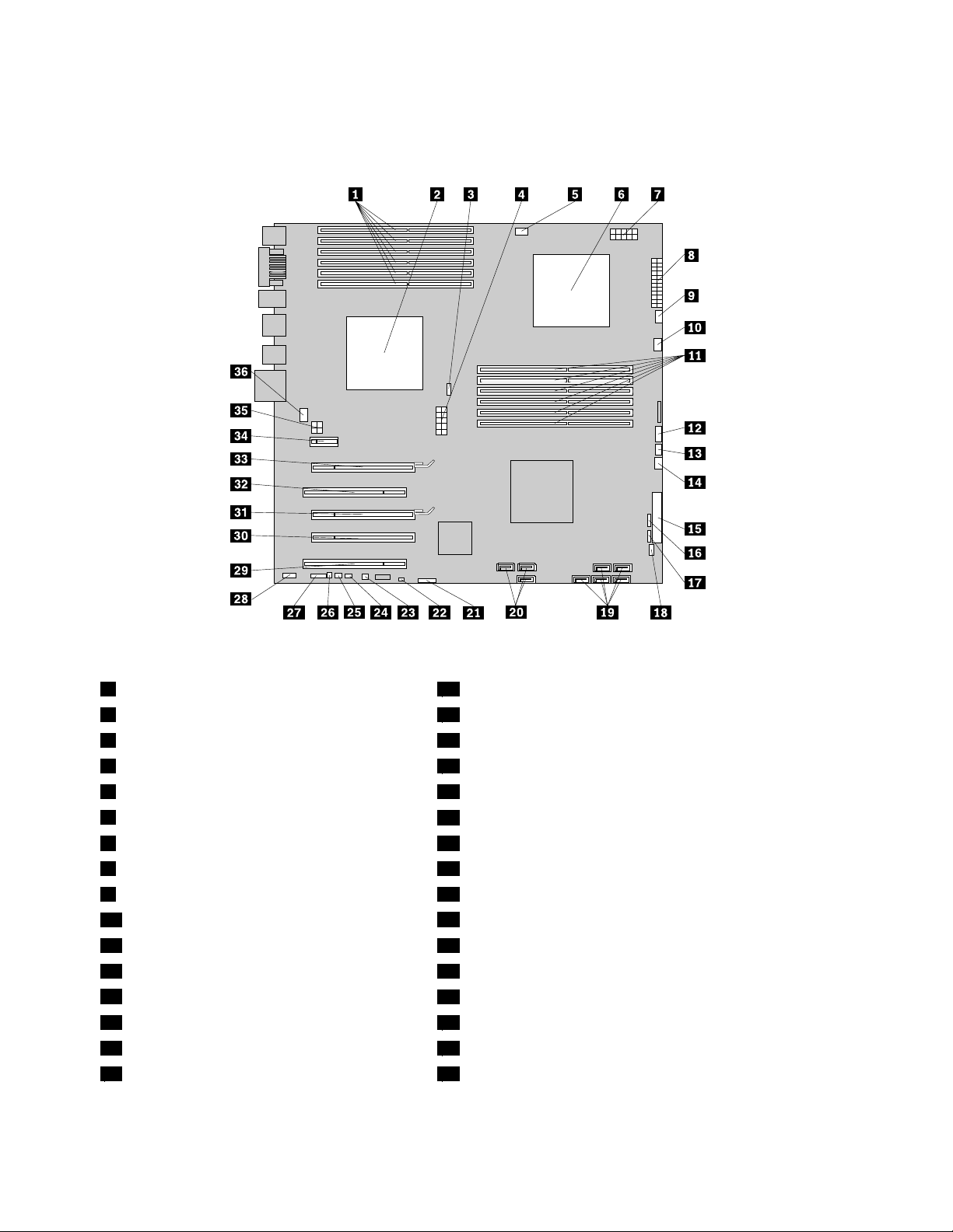
Identifyingpartsonthesystemboard
Figure4“Systemboardpartslocations”onpage8showsthelocationofthepartsonthesystemboard.
Figure4.Systemboardpartslocations
1CPU1memoryslots(6)19Harddiskdriveconnectors(5)
2Microprocessorandheatsink1
3CPU1fanconnector
4CPU112Vpowerconnector22ClearCMOS/Recoveryjumper
5CPU1memoryfanconnector
6Microprocessorandheatsink2
7CPU212Vpowerconnector25PS/2keyboardandmouseconnector
824-pinpowerconnector26Internalspeakerconnector
9CPU2fanconnector27COM2connector
10CPU2memoryfanconnector
11CPU2memoryslots(6)29PCIadaptercardslot
12Powerswitch/LEDsconnector30PCIExpressx4graphicsadaptercardslot(x16mechanical)
13AuxiliaryLEDconnector
14Harddiskdrivefanconnector
15Diskettedriveconnector
16Cardreaderconnector34PCIExpressx1adaptercardslot
20Opticaldriveconnectors(3)
21Battery
23Thermalsensorconnector
24Coverpresenceswitchconnector
28Frontaudioconnector
31PCIExpressx16graphicsadaptercardslot
32PCIadaptercardslot
33PCIExpressx16graphicsadaptercardslot
8ThinkStationHardwareInstallationandReplacementGuide
Page 15

17FrontUSBconnector35Graphiccardpowerconnector
18FrontIEEE1394connector
36Rearfanconnector
Chapter2.Overview9
Page 16

10ThinkStationHardwareInstallationandReplacementGuide
Page 17

Chapter3.Installingoptionsandreplacinghardware
Thischapterisanintroductiontothefeaturesandoptionsthatareavailableforyourcomputer.Youcan
expandthecapabilitiesofyourcomputerbyaddingmemorymodules,adaptercards,ordrives.When
installinganoption,usetheseinstructionsalongwiththeinstructionsthatcomewiththeoption.
Attention:Donotopenyourcomputerorattemptanyrepairbeforereadingandunderstandingthe“Importantsafety
information”intheThinkStationSafetyandWarrantyGuidethatcamewithyourcomputer.T oobtainacopyofthe
ThinkStationSafetyandWarrantyGuide,goto:
http://support.lenovo.com
Note:UseonlypartsprovidedbyLenovo.
Installingexternaloptions
Externalspeakers,aprinter,orascannercanbeconnectedtoyourcomputer.Forsomeexternaloptions,
youmustinstalladditionalsoftwareinadditiontomakingthephysicalconnection.Whenaddinganexternal
option,see“Locatingconnectorsontherearofyourcomputer”onpage5
connectorsonthefrontofyourcomputer”onpage4toidentifytherequiredconnector,andthenusethe
instructionsthatareincludedwiththeoptiontohelpyoumaketheconnectionandinstallanysoftware
ordevicedriversthatarerequiredfortheoption.
Installinginternaloptions
and“Locatingcontrolsand
Important:Read“Handlingstatic-sensitivedevices”onpage3beforeremovingthecomputercover.
Removingthecomputercover
CAUTION:
Turnoffthecomputerandwaitthreetoveminutestoletthecomputercoolbeforeremovingthe
computercover.
Toremovethecomputercover:
1.Removeanymediafromthedrivesandshutdownyouroperatingsystem.Turnoffallattacheddevices.
Turnoffthecomputer.
2.Unplugallpowercordsfromelectricaloutlets.
3.Disconnectthecablesattachedtothecomputer.Thisincludespowercords,input/output(I/O)cables,
andanyothercablesthatareconnectedtothecomputer.See“Locatingcontrolsandconnectorsonthe
frontofyourcomputer”onpage4and“Locatingconnectorsontherearofyourcomputer”onpage5.
4.Removeanylockingdevices,suchasacablelockorpadlockthatsecuresthecomputercover.See
Chapter5“Securityfeatures”onpage47.
©CopyrightLenovo2009,2011
11
Page 18
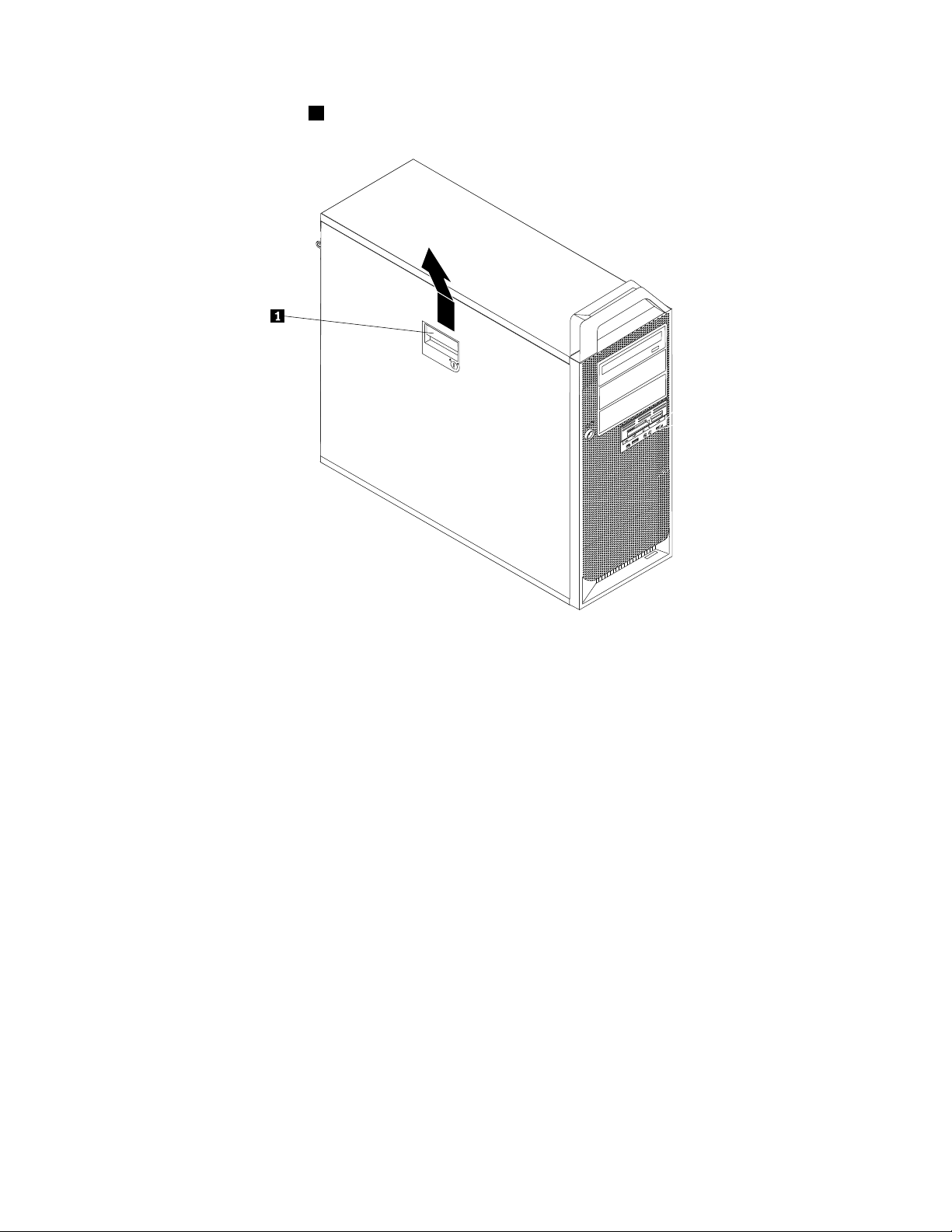
5.Disengagethecoverlatch1andremovethecover.Placethecoveronaatsurface.
Figure5.Removingthecomputercover
Removingthefrontbezel
Toremovethefrontbezel:
1.Removethecomputercover.See“Removingthecomputercover”onpage11.
12ThinkStationHardwareInstallationandReplacementGuide
Page 19
2.Removethefrontbezelbyreleasingthetwoplastictabsontheleftsideandpivotingthebezeloutward.
Figure6.Removingthefrontbezel
3.Laythefrontbezelonaatsurface.
4.T oreinstallthebezel,aligntheplastictabsontherightsideofthebezelwiththecorrespondingholesin
thechassis,thenpivotthebezelinwarduntilitsnapsintopositionontheleftside.
Accessingsystemboardcomponents
Toaccessthesystemboardcomponents:
1.Removethecomputercover.See“Removingthecomputercover”onpage11.
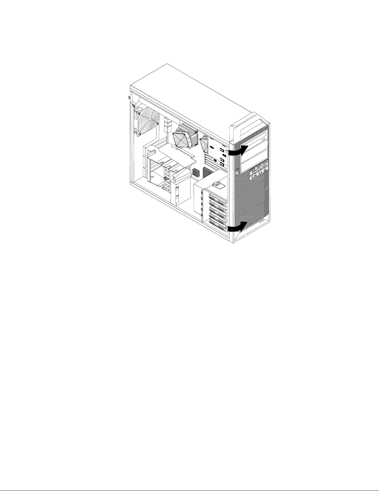
2.Unlatchandopentheadaptercardretainer.
Chapter3.Installingoptionsandreplacinghardware13
Page 20
3.Removetheharddiskdrivefanductbypressingdownwardsonthetopoftheductandthenrotatingthe
duct.
Figure7.Removingtheharddiskdrivefanduct
4.Removetheadaptercardsifnecessary.See“Replacingadaptercards”onpage30.
14ThinkStationHardwareInstallationandReplacementGuide
Page 21

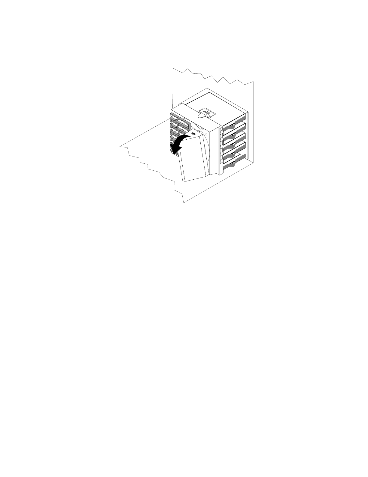
5.Y oumightneedtoremovetheharddiskdrivefanbrackettogaineasyaccesstosomeinternal
components.Toremovethebracket,pressdownwardontheharddiskdrivefanbracketlatchandthen
pivotthebrackettoremovetheharddiskdrivefanandbracketfromthechassis.
Figure8.Removingtheharddiskdrivefanandbracket
Installinginternaldrives
Thissectionprovidesinformationandinstructionsforinstallingtheinternaldrives.
Internaldrivesaredevicesthatyourcomputerusestoreadandstoredata.Youcanadddrivestoyour
computertoincreasestoragecapacityandtoenableyourcomputertoreadothertypesofmedia.Someof
thetypesofdrivesthatareavailableforyourcomputerare:
•SerialAttachedSCSI(SAS)harddiskdrives
•SerialATA(SA T A)harddiskdrives
•SA T Aopticaldrives,suchasCDdrivesorDVDdrives
•Removablemediadrives
Internaldrivesareinstalledinbays.Inthisbook,thebaysarereferredtoasbay1,bay2,andsoon.
Whenyouinstallaninternaldrive,itisimportanttonotethetypeandsizeofthedrivethatyoucaninstallin
eachbay.Also,itisimportanttocorrectlyconnecttheinternaldrivecablestotheinstalleddrive.
Chapter3.Installingoptionsandreplacinghardware15
Page 22

Drivespecications
Yourcomputercomeswiththefollowingfactory-installeddrives:
•Anopticaldriveinbay1
•Ablankbayforexpansionoranoptionalopticaldriveinbay2orbay3(somemodels)
•A3.5-inchdiskettedriveoracardreaderinbay4(somemodels)
•Uptoveharddiskdrivesinbay5(variesbymodel)
Anybaythatdoesnothaveadriveinstalledhasastaticshieldandbaypanelinstalled.
Figure9“Drivebaylocations”onpage16
showsthelocationofthedrivebays.
Figure9.Drivebaylocations
Thefollowinglistdescribesthetypesandsizeofdrivesthatyoucaninstallineachbay:
1Bay1-Maximumheight:43mm(1.7inches)Opticaldrives,suchasCDdriveorDVDdrive
(preinstalledinsomemodels)
2Bay2-Maximumheight:43mm(1.7inches)OptionaldrivessuchasCDdriveorDVDdrive
(preinstalledinsomemodels)
3Bay3-Maximumheight:43mm(1.7inches)OptionaldrivessuchasCDdriveorDVDdrive
(preinstalledinsomemodels)
4Bay4-Maximumheight:26.1mm(1inch)3.5-inchdiskettedriveorcardreader(preinstalled
insomemodels)
5Bay5
Uptoveharddiskdrives(variesbymodel)
16ThinkStationHardwareInstallationandReplacementGuide
Page 23

Installingadriveinbay2orbay3
Toinstallanopticaldriveinbay2orbay3:
1.Removethecomputercover.See“Removingthecomputercover”onpage11.
2.Removethefrontbezel.See“Removingthefrontbezel”onpage12.
Note:Thereisadriveretainerbracketontheinsideofthefrontbezelwherethedriveistobelocated.If
thereisnodriveinstalled,therearedriveretainerbracketsforeachdrive.Removethedriveretainer
bracketanduseittoinstallthedrive.
3.Removetheplasticdrivecoverfromthebezel.
4.Removethemetalstaticshieldfromthedrivebayusingyourngerstopullitoutward.
5.Installtheretainerbracketontheleftsideofthedrivetobeinstalled.
Figure10.Installingtheretainerbracket
6.Slidethedriveintothebayuntilitlocksintoposition.
Figure11.Installinganopticaldrive
7.T oreinstallthefrontbezel,aligntheplastictabsontherightsideofthebezelwiththecorresponding
holesinthechassis,thenpivotthefrontbezelinwarduntilitsnapsintopositionontheleftside.
Chapter3.Installingoptionsandreplacinghardware17
Page 24

8.Locateanavailableopticaldriveconnectoronthesystemboard.See“Identifyingpartsonthesystem
board”onpage8.
9.Usingthesignalcablethatcamewiththenewdrive,connectoneendofthesignalcabletothedrive
andtheotherendtotheavailableopticaldriveconnectoronthesystemboard.
10.Locateoneoftheextrave-wirepowercablesandconnectittothedrive.
Figure12.Connectingthedrive
Whattodonext:
•T oworkwithanotheroption,gototheappropriatesection.
•T ocompletetheinstallation,gotoChapter4“Completingthepartsreplacement”onpage45.
Installingadiskettedriveorcardreaderinbay4
Toinstalladiskettedriveorcardreaderinbay4:
1.Removethecomputercover.See“Removingthecomputercover”onpage11.
2.Removethefrontbezel.See“Removingthefrontbezel”onpage12.
3.Removetheplasticpanelinthebezelbysqueezingtheplastictabsthatsecurethepanelontheinside
ofthebezel.
Note:Thereisadriveretainerbracketforeachdriveontheinsideofthefrontbezelwherethedriveisto
belocated.Removethedriveretainerbracketanduseittoinstallthedrive.
4.Installtheretainerbracketonthediskettedriveorcardreader.
Figure13.Installingtheretainerbracket
5.Removethestaticshieldfromthecomputerchassis.
18ThinkStationHardwareInstallationandReplacementGuide
Page 25

6.Slidethediskettedriveorcardreaderintothedrivebayuntilitsnapsintoposition.See“Locating
components”onpage7.
Figure14.Installinganewdiskettedriveorcardreader
7.Connectthediskettedrivetothediskettedriveconnectoronthesystemboard.Ifyouareinstallinga
cardreader,connectittothecardreaderconnectoronthesystemboard.See“Identifyingpartson
thesystemboard”onpage8.
8.Reinstallthefrontbezel.
Whattodonext:
•T oworkwithanotheroption,gototheappropriatesection.
•T ocompletetheinstallation,gotoChapter4“Completingthepartsreplacement”onpage45.
Installingaharddiskdriveinbay5
Thissectionprovidesinstructionsonhowtoinstallaharddiskdrive.
Note:YoucaninstallacombinationofSAT AandSASharddiskdriveswithinthesamecomputer.However,
SATAandSASharddiskdrivescannotbeinstalledwithinthesameRAIDarray.
Toinstallanewharddiskdrive:
1.Removethecomputercover.See“Removingthecomputercover”onpage11.
2.Locateoneoftheemptyharddiskdriveslotsinbay5.See“Locatingcomponents”onpage7.Each
emptyharddiskdriveslothasasparebracket.
3.Pullthehandletoremoveasparebracket.
Chapter3.Installingoptionsandreplacinghardware19
Page 26

4.T oinstallthenewharddiskdriveintothebracket,exthebracket,andthenalignpin1,pin2,pin
3,andpin4onthebracketwiththeholesintheharddiskdrive.Donottouchthecircuitboard5
onthebottomoftheharddiskdrive.
Figure15.Installinga3.5-inchharddiskdriveintothebracket
Note:Ifyouareinstallinga2.5-inchharddiskdriveintothebracket,exthebracket,andthenalignpin
1,pin2,pin3,andpin4onthebracketwiththeholesintheharddiskdriveadapter5.
Figure16.Installinga2.5-inchharddiskdriveintothebracket
5.Installtheharddiskdriveandbracketintothedrivebay.
6.Usingthesignalcablethatcamewiththenewdrive,connectoneendofthesignalcabletothedrive.
Locateoneoftheextrave-wirepowercablesandconnectittothedrive.
Note:ThesignalcablewillbedifferentdependingonwhetheryouareinstallingaSAT Aharddisk
driveoraSASharddiskdrive.
20ThinkStationHardwareInstallationandReplacementGuide
Page 27

Figure17.Connectinga3.5-inchSATAharddiskdrive
Figure18.Connectinga2.5-inchSATAharddiskdrive
Figure19.Connectinga3.5-inchSASharddiskdrive
7.Connecttheotherendofthesignalcabletooneoftheavailableharddiskdriveconnectorsonthe
systemboard.See“Identifyingpartsonthesystemboard”onpage8.
Whattodonext:
•T oworkwithanotheroption,gototheappropriatesection.
Chapter3.Installingoptionsandreplacinghardware21
Page 28

•T ocompletetheinstallation,gotoChapter4“Completingthepartsreplacement”onpage45.
Replacingthebattery
Yourcomputerhasaspecialtypeofmemorythatmaintainsthedate,time,andsettingsforbuilt-infeatures,
suchasserial-portassignments(conguration).Abatterykeepsthisinformationactivewhenyouturn
offthecomputer.
Thebatterynormallyrequiresnochargingormaintenancethroughoutitslife;however,nobatterylasts
forever.Ifthebatteryfails,thedate,time,andcongurationinformation(includingpasswords)arelost.An
errormessageisdisplayedwhenyouturnonthecomputer.
Refertothe"Lithiumbatterynotice"intheThinkStationSafetyandWarrantyGuideforinformationabout
replacinganddisposingofthebattery.
Toreplacethebattery:
1.T urnoffthecomputeranddisconnectthepowercordfromtheelectricaloutletandfromthecomputer.
2.Removethecomputercover.See“Removingthecomputercover”onpage11.
3.Accessthesystemboard.See“Accessingsystemboardcomponents”onpage13.
4.Locatethebattery.See“Identifyingpartsonthesystemboard”onpage8.
5.Removetheoldbattery.
Figure20.Removingtheoldbattery
6.Installthenewbattery.
Figure21.Installingthenewbattery
7.Reinstallanyadaptercardthatwasremoved.Replacethecomputercoverandconnectthecables.
SeeChapter4“Completingthepartsreplacement”onpage45
Note:Whenthecomputeristurnedonforthersttimeafterreplacingthebattery,anerrormessage
mightbedisplayed.Thisisnormalafterreplacingthebattery.
8.T urnonthecomputerandallattacheddevices.
9.UsetheSetupUtilityprogramtosetthedateandtimeandanypasswords.See"UsingtheSetup
Utility"intheThinkStationUserGuide.
.
22ThinkStationHardwareInstallationandReplacementGuide
Page 29

Replacingthepowersupplyassembly
Attention:Donotopenyourcomputerorattemptanyrepairbeforereadingandunderstandingthe“Importantsafety
information”intheThinkStationSafetyandWarrantyGuidethatcamewithyourcomputer.T oobtainacopyofthe
ThinkStationSafetyandWarrantyGuide,goto:
http://support.lenovo.com
Thissectionprovidesinstructionsonhowtoreplacethepowersupplyassembly.
Toreplacethepowersupplyassembly:
1.Removethecomputercover.See“Removingthecomputercover”onpage11.
2.Laythecomputeronitsside.
3.Locatethepowersupplyassembly.See“Locatingcomponents”onpage7.
4.Disconnectthepowersupplycables1,2,3,and4fromthesystemboardconnectors,adapter
cards,andalldrives.
Figure22.Powersupplycableconnectors
5.Removethepowersupplycablesfromanycableclipsandties.
Chapter3.Installingoptionsandreplacinghardware23
Page 30

6.Removethesixpowersupplyretainingscrewsattherearofthechassisandinsidethechassis.
Figure23.Removingthepowersupplyretainingscrews
7.Slidethepowersupplyassemblytowardthefrontofthecomputerandliftitoutfromthechassis.
8.Ensurethatthenewpowersupplyisthecorrectreplacement.Somepowersuppliesautomatically
sensethevoltage,somepowersuppliesarevoltagespecic,andsomepowersupplieshavea
voltage-selectionswitch.Ifthereisavoltage-selectionswitch,useaballpointpentoslidetheswitch,if
necessary.
Note:Formodelsthathaveavoltage-selectionswitch:
•Ifthevoltagesupplyrangeis100–127VAC,settheswitchto115V.
•Ifthevoltagesupplyrangeis200–240VAC,settheswitchto230V.
9.Installthenewpowersupplyintothechassissothatthescrewholesinthepowersupplyalignwith
thoseinthechassis.
Note:UseonlythescrewsprovidedbyLenovo.
10.Installandtightenthefourscrewsattherearofthechassistosecurethepowersupply.
11.Installandtightenthetwoscrewsthatsecurethepowersupplytotheinsideofthechassis.
12.Reconnectallpowersupplycablestothedrives,adaptercards,andthesystemboard.Makesureto
reconnectthepowercabletothegraphicscardsthatrequireanadditionalcable.
13.GotoChapter4“Completingthepartsreplacement”onpage45.
24ThinkStationHardwareInstallationandReplacementGuide
Page 31

Installingorreplacingamemorymodule
Attention:Donotopenyourcomputerorattemptanyrepairbeforereadingandunderstandingthe“Importantsafety
information”intheThinkStationSafetyandWarrantyGuidethatcamewithyourcomputer.T oobtainacopyofthe
ThinkStationSafetyandWarrantyGuide,goto:
http://support.lenovo.com
CAUTION:
Thememorymodulesmightbeveryhot.T urnoffthecomputerandwaitthreetoveminutestolet
thecomputercoolbeforeremovingthecomputercover.
Yourcomputerhas12slotsforinstallingorreplacingDDR3ECCUDIMMs(doubledatarate3errorcorrection
codeunbuffereddualin-linememorymodules)orDDR3ECCRDIMMs(doubledatarate3errorcorrection
coderegistereddualin-linememorymodules).
Wheninstallingorreplacingmemorymodules,usethefollowingguidelines:
•UseeitherDDR3ECCUDIMMsorDDR3ECCRDIMMsforyourcomputer.Donotinstallboththe
UDIMMsandRDIMMsintothesamecomputer.
•Use1GB,2GB,or4GBUDIMMsinanycombinationuptoamaximumof48GB.
•Use1GB,2GB,4GB,or8GBRDIMMsinanycombinationuptoamaximumof96GB.
•AlwaysinstallDIMMsinthenumericalorderprintedonthesystemboard(DIMM1,DIMM2,DIMM3,and
soon).Installmemorymodulesintothebluecolormemoryslotsrst.
•IfyourcomputerhasonlyoneCPUinstalled,besuretoinstallmemorymodulesonlyinthememory
slotsadjacenttothatCPU.
•IfyourcomputerhastwoCPUsinstalled,installequalnumbersofmemorymodulesinbothsetsofCPU
DIMMslotsformaximumperformance.
Toinstallorreplaceamemorymodule:
1.Removethecomputercover.See“Removingthecomputercover”onpage11.
2.Laythecomputeronitsside.
3.Locatethememoryslots.See“Identifyingpartsonthesystemboard”onpage8.
4.Forsomecomputermodels,youmightneedtoremovethememoryfanducttoaccessthememory
slots.Toremovethememoryfanduct,disconnectthememoryfancablefromthesystemboard,
removetheblueshippingclip,pressinwardonthetwotabs,pivotthefanduct,andthendisengagethe
otherendoftheduct.
Note:Notallcomputermodelshavethememoryfanductandblueshippingclip.
Figure24.Removingthememoryfanduct
Chapter3.Installingoptionsandreplacinghardware25
Page 32

5.Dependingonwhetheryouareinstallingorreplacingamemorymodule,dooneofthefollowing:
•Ifyouarereplacinganoldmemorymodule,opentheretainingclipsandgentlypullthememory
moduleoutofthememoryslot.
Figure25.Removingamemorymodule
•Ifyouareinstallingamemorymodule,opentheretainingclipsofthememoryslotintowhichyou
wanttoinstallthememorymodule.
Figure26.Openingtheretainingclips
26ThinkStationHardwareInstallationandReplacementGuide
Page 33

6.Positionthenewmemorymoduleoverthememoryslot.Makesurethenotch1onthememorymodule
alignscorrectlywiththeslotkey2onthesystemboard.Pushthememorymodulestraightdowninto
theslotuntiltheretainingclipsclose.
Figure27.Installingthememorymodule
7.T oinstallthememoryfan,engagetherearoftheductwiththeretaineronthesystemboardand
thenpivottheductdownwardsuntiltheductsnapsintoposition.Reconnectthememoryfancable
tothesystemboard.
Figure28.Installingthememoryfanduct
8.Reinstalltheblueshippingclipifyourcomputerneedstoberepackagedandshippedinthefuture.
9.GotoChapter4“Completingthepartsreplacement”onpage45.
Note:Yoursystemmemoryspeedisdeterminedbyanumberoffactors,includingthemicroprocessor
modelandthetype,speed,size(capacity),andnumberofDIMMsinstalled.SeeAppendixA“System
memoryspeed”onpage49formoreinformation.
Installingorreplacingadaptercards
Thissectionprovidesinstructionsforinstallingadaptercards.Yourcomputerhasthefollowingsixexpansion
slotsforinstallingorreplacingadaptercards:
•T woPCIadaptercardslots
•OnePCIExpressx1adaptercardslot
•OnePCIExpressx4adaptercardslot
•T woPCIExpressx16graphicsadaptercardslots
Chapter3.Installingoptionsandreplacinghardware27
Page 34

Installingadaptercards
Toinstallanadaptercard:
1.Removethecomputercover.See“Removingthecomputercover”onpage11.
2.Unlatchandopentheadaptercardretainer.
3.Removethemetalcoverfortheappropriateadaptercardslotifyouareinstallinganadaptercard.
4.Ifyouareinstallingafulllengthadaptercard,removetheductontheharddiskdrivefanbracketby
pressingdownwardsonthetopoftheductandthenrotatingtheduct.
Figure29.Removingtheharddiskdrivefanduct
5.Removetheadaptercardfromitsstatic-protectivepackage.
28ThinkStationHardwareInstallationandReplacementGuide
Page 35

6.Installtheadaptercardintotheappropriateadaptercardslotonthesystemboard.See“Identifying
partsonthesystemboard”onpage8.
Figure30.Installinganadaptercard
Chapter3.Installingoptionsandreplacinghardware29
Page 36

7.Connectanyadaptercardcabletothesystemboard.
8.Latchtheadaptercardretainertosecuretheadaptercard.
Whattodonext:
•T oworkwithanotheroption,gototheappropriatesection.
•T ocompletetheinstallation,gotoChapter4“Completingthepartsreplacement”onpage45
Replacingadaptercards
Toreplaceanadaptercard:
1.Removethecomputercover.See“Removingthecomputercover”onpage11.
2.Unlatchandopenthecardretainer.
3.T akenoteofthelocationofallcableconnectionsontheadaptercard.Itwillbenecessarytoreconnect
themproperlywheninstallinganewcard.
4.Disconnectallcablesconnectedtotheadaptercard.See“Identifyingpartsonthesystemboard”
onpage8.
5.T oremovetheadaptercard,dooneofthefollowing:
•Ifyouarereplacingafulllengthadaptercard,removetheductontheharddiskdrivefanbracketby
pressingdownwardsonthetopoftheductandthenrotatingtheduct.Grasptheadaptercardand
pulltheadaptercardoutoftheslot.
.
Figure31.Removingafulllengthadaptercard
•Someadaptercardsareheldinplacebyaretaininglatch,suchasvideocardsthataresmallerthan
512MB.Presstheadaptercardretaininglatch
cardandthenpulltheadaptercardoutoftheslot.
30ThinkStationHardwareInstallationandReplacementGuide
1asshowntodisengagethelatch.Grasptheadapter
Page 37

Figure32.Pressingthelatchandremovingtheadaptercard
Note:Theadaptercardtstightlyintothecardslot.Ifnecessary,alternatemovingeachsideofthe
adaptercardasmallamountuntilitisremovedfromtheadaptercardslot.
6.T oinstallanadaptercard,see“Installingadaptercards”onpage28.
7.GotoChapter4“Completingthepartsreplacement”onpage45.
Replacingtheheatsinkandfanassembly
Attention:Donotopenyourcomputerorattemptanyrepairbeforereadingandunderstandingthe“Importantsafety
information”intheThinkStationSafetyandWarrantyGuidethatcamewithyourcomputer.T oobtainacopyofthe
ThinkStationSafetyandWarrantyGuide,goto:
http://support.lenovo.com
CAUTION:
Theheatsinkandfanassemblymightbeveryhot.T urnoffthecomputerandwaitthreetove
minutestoletthecomputercoolbeforeremovingthecomputercover.
Thissectionprovidesinstructionsonhowtoreplacetheheatsinkandfanassembly.
Toreplacetheheatsinkandfanassembly:
Chapter3.Installingoptionsandreplacinghardware31
Page 38

1.Removethecomputercover.See“Removingthecomputercover”onpage11.
2.Laythecomputeronitssideforeasieraccesstotheheatsinkandfanassembly.
3.Y ourcomputersupportstwoheatsinkandfanassemblies.Locatetheheatsinkandfanassemblyyou
wanttoreplace.See“Locatingcomponents”onpage7.
4.Removetheheatsinkandfanassemblycablefromthesystemboard.Notethecablelocation.
5.Followthissequencetoremovethefourscrewsthatsecuretheheatsinkandfanassemblytothe
systemboard:
a.Partiallyremovescrew1,thenfullyremovescrew2,andthenfullyremovescrew1.
b.Partiallyremovescrew3,thenfullyremovescrew4,andthenfullyremovescrew3.
Note:Thefourscrewscanberemovedfromthesystemboard,buttheycannotberemovedfromthe
heatsinkandfanassembly.
Figure33.Removingtheheatsinkandfanassembly
6.Carefullylifttheheatsinkandfanassemblyoffthesystemboard.
Notes:
a.Y oumighthavetogentlytwisttheheatsinkandfanassemblytofreeitfromthemicroprocessor.
b.Donottouchthethermalgreasewhilehandlingtheheatsinkandfanassembly.
7.Removetheplasticcoverfromthebottomofthenewheatsinkandfanassemblytoexposethethermal
grease(thiscoverprotectsthethermalgreasefromcontamination).
Notes:
a.Donotremovetheplasticcoveruntilyouarereadytoinstalltheheatsinkandfanassemblyon
themicroprocessor.
b.Donottouchthethermalgreaseontheheatsinkandfanassembly.
c.Donotputtheheatsinkandfanassemblyanywhereexceptonthemicroprocessoraftertheplastic
coverhasbeenremovedandthethermalgreaseexposed.
32ThinkStationHardwareInstallationandReplacementGuide
Page 39

8.Positionthenewheatsinkandfanassemblyonthemicroprocessorsothatthefourscrewsarealigned
withtheholesonthesystemboard.
9.Followthissequencetoinstallthefourscrewstosecuretheheatsinkandfanassembly:
a.Partiallytightenscrew1,thenfullytightenscrew2,andthenfullytightenscrew1.
b.Partiallytightenscrew3,thenfullytightenscrew4,andthenfullytightenscrew3.
10.Reconnecttheheatsinkfanassemblycabletothesystemboard.
11.GotoChapter4“Completingthepartsreplacement”onpage45.
Replacingaharddiskdrive
Attention:Donotopenyourcomputerorattemptanyrepairbeforereadingandunderstandingthe“Importantsafety
information”intheThinkStationSafetyandWarrantyGuidethatcamewithyourcomputer.T oobtainacopyofthe
ThinkStationSafetyandWarrantyGuide,goto:
http://support.lenovo.com
Thissectionprovidesinstructionsonhowtoreplacetheharddiskdrive.
Important:Whenyoureceiveanewharddiskdrive,youalsoreceiveasetofProductRecoverydiscs.
ThesetofProductRecoverydiscswillenableyoutorestorethecontentsoftheharddiskdrivetothe
factory-installedstate.Formoreinformationonrecoveringfactory-installedsoftware,referto“Recovering
software”inyourThinkStationUserGuide.
Note:YoucaninstallacombinationofSAT AandSASharddiskdriveswithinthesamecomputer.However,
SATAandSASharddiskdrivescannotbeinstalledwithinthesameRAIDarray.
Toreplaceaharddiskdrive:
1.Removethecomputercover.See“Removingthecomputercover”onpage11.
2.Locatetheharddiskdrive.See“Locatingcomponents”onpage7.
3.Disconnectthesignalandpowercablesfromtheharddiskdrive.
Chapter3.Installingoptionsandreplacinghardware33
Page 40

4.Pullthehandleoftheharddiskdrivebrackettoremovetheharddiskdrive.
Figure34.Removingaharddiskdrive
5.Removethefailingharddiskdrivefromthebracketbyexingthebracket.
6.Installthenewharddiskdriveintothebracket.See“Installingaharddiskdriveinbay5”onpage19.
7.Installtheharddiskdriveandbracketintothedrivebay.
8.Reconnectthesignalandpowercablestothenewharddiskdrive.See“Installingaharddiskdrive
inbay5”onpage19.
9.GotoChapter4“Completingthepartsreplacement”onpage45.
Replacinganopticaldrive
Attention:Donotopenyourcomputerorattemptanyrepairbeforereadingandunderstandingthe“Importantsafety
information”intheThinkStationSafetyandWarrantyGuidethatcamewithyourcomputer.T oobtainacopyofthe
ThinkStationSafetyandWarrantyGuide,goto:
http://support.lenovo.com
Thissectionprovidesinstructionsonhowtoreplacetheopticaldrive.
Toreplacetheopticaldrive:
1.Removethecomputercover.See“Removingthecomputercover”onpage11.
2.Removethefrontbezel.See“Removingthefrontbezel”onpage12.
3.Locatetheopticaldrive.See“Locatingcomponents”onpage7.
4.Notethelocationoftheopticaldrivecables.Disconnectthesignalandpowercablesfromtherearof
theopticaldrive.
34ThinkStationHardwareInstallationandReplacementGuide
Page 41

5.Pressthedrivelatch1andslidetheopticaldriveoutthefrontofthechassis.
Figure35.Removingtheopticaldrive
6.Removetheretainerbracketfromthedrivebeingreplacedandinstallitonthenewdrive.
Figure36.Retainerbracketforopticaldrive
7.Slidethenewopticaldriveintotheopticaldrivebayfromthefrontuntilitsnapsintoposition.
8.Connectthesignalandpowercablestothenewdrive.
9.Reinstallthefrontbezel.
10.GotoChapter4“Completingthepartsreplacement”onpage45.
Replacingthediskettedriveorcardreader
Attention:Donotopenyourcomputerorattemptanyrepairbeforereadingandunderstandingthe“Importantsafety
information”intheThinkStationSafetyandWarrantyGuidethatcamewithyourcomputer.T oobtainacopyofthe
ThinkStationSafetyandWarrantyGuide,goto:
http://support.lenovo.com
Chapter3.Installingoptionsandreplacinghardware35
Page 42

Thissectionprovidesinstructionsonhowtoreplacethediskettedriveorcardreader.
Toreplacethediskettedriveorcardreader:
1.Removethecomputercover.See“Removingthecomputercover”onpage11.
2.Removethefrontbezel.See“Removingthefrontbezel”onpage12.
3.Locatethediskettedriveorcardreader.See“Locatingcomponents”onpage7.
4.Disconnectthesignalandpowercablesfromtherearofthediskettedrive.Ifyouarereplacinga
cardreader,disconnectthecardreadercablefromthesystemboard.See“Identifyingpartsonthe
systemboard”onpage8.
5.Pressthedrivelatch1andslidethediskettedriveorcardreaderoutthefrontofthechassis.
Figure37.Removingthediskettedriveorcardreader
6.Removetheretainerbracketfromthefailingdiskettedriveorcardreaderandinstallitonthenew
diskettedriveorcardreader.
Figure38.Installingtheretainerbracket
7.Slidethenewdiskettedriveorcardreaderintothedrivebayuntilitsnapsintoposition.
8.Connectthesignalcableandpowercabletothenewdiskettedrive.Ifyouareinstallingacardreader,
connectthecardreadercabletothecardreaderconnectoronthesystemboard.See“Identifying
partsonthesystemboard”onpage8.
36ThinkStationHardwareInstallationandReplacementGuide
Page 43

9.Reinstalltheharddiskdrivefanbracketifremoved.
10.Reinstallthefrontbezel.
11.GotoChapter4“Completingthepartsreplacement”onpage45.
Replacingthefrontpanelconnectorassembly
Attention:Donotopenyourcomputerorattemptanyrepairbeforereadingandunderstandingthe“Importantsafety
information”intheThinkStationSafetyandWarrantyGuidethatcamewithyourcomputer.T oobtainacopyofthe
ThinkStationSafetyandWarrantyGuide,goto:
http://support.lenovo.com
Thissectionprovidesinstructionsonhowtoreplacethefrontpanelconnectorassembly.
Toreplacethefrontpanelconnectorassembly:
1.Removethecomputercover.See“Removingthecomputercover”onpage11.
2.Removethefrontbezel.See“Removingthefrontbezel”onpage12.
3.Locatethefrontpanelconnectorassembly.
4.Accesssystemboardcomponents.See“Accessingsystemboardcomponents”onpage13.
5.Disconnectthefrontaudio,frontUSB,auxiliaryLED,andIEEE1394cablesfromthesystemboardand
notetheroutesofthecables.
6.Removethetwoscrewsthatsecurethefrontpanelconnectorassemblytothechassisandthen
completelyreleasethefrontpanelconnectorassemblyfromthechassis.
Figure39.Removingthefrontpanelconnectorassembly
Chapter3.Installingoptionsandreplacinghardware37
Page 44

7.Alignthescrewholesinthenewfrontpanelconnectorassemblywiththeholesinthechassis.Installthe
twoscrewstosecuretheassembly.
8.Reconnectallthecablestothesystemboard.See“Identifyingpartsonthesystemboard”onpage8.
9.Reinstalltheharddiskdrivefanbracketifremoved.
10.Reinstallthefrontbezel.
11.GotoChapter4“Completingthepartsreplacement”onpage45.
Replacingtheharddiskdrivefanassembly
Attention:Donotopenyourcomputerorattemptanyrepairbeforereadingandunderstandingthe“Importantsafety
information”intheThinkStationSafetyandWarrantyGuidethatcamewithyourcomputer.T oobtainacopyofthe
ThinkStationSafetyandWarrantyGuide,goto:
http://support.lenovo.com
Thissectionprovidesinstructionsonhowtoreplacetheharddiskdrivefanassembly.
Toreplacetheharddiskdrivefanassembly:
1.Removethecomputercover.See“Removingthecomputercover”onpage11.
2.Locatetheharddiskdrivefanassembly.See“Locatingcomponents”onpage7.
3.Unlatchandopentheadaptercardretainer.
4.Pressdownwardsonthetopoftheharddiskdrivefanduct,andthenrotatetheducttoremoveit.
Figure40.Removingtheharddiskdrivefanduct
38ThinkStationHardwareInstallationandReplacementGuide
Page 45

5.Presstheharddiskdrivefanassemblybracketlatchdownwardsandpivotthebrackettoremoveit
fromthechassis.
Figure41.Removingtheharddiskdrivefanassemblybracket
6.Disconnecttheharddiskdrivefanassemblycablefromthesystemboard.
7.Theharddiskdrivefanassemblyisattachedtothebracketbyfourrubbermounts1.Removethefan
assemblybygentlypullingitoutofthebracket.
Figure42.Removingtheharddiskdrivefanassembly
8.Installthenewharddiskdrivefanassemblybyaligningtherubbermountsofthefanassemblywiththe
holesintheharddiskdrivefanassemblybracketandpushingtherubbermountsthroughtheholes.
9.Connecttheharddiskdrivefanassemblycabletothesystemboardandtheninstallthebracketand
harddiskdrivefanassemblytothechassis.
10.GotoChapter4“Completingthepartsreplacement”onpage45.
Chapter3.Installingoptionsandreplacinghardware39
Page 46
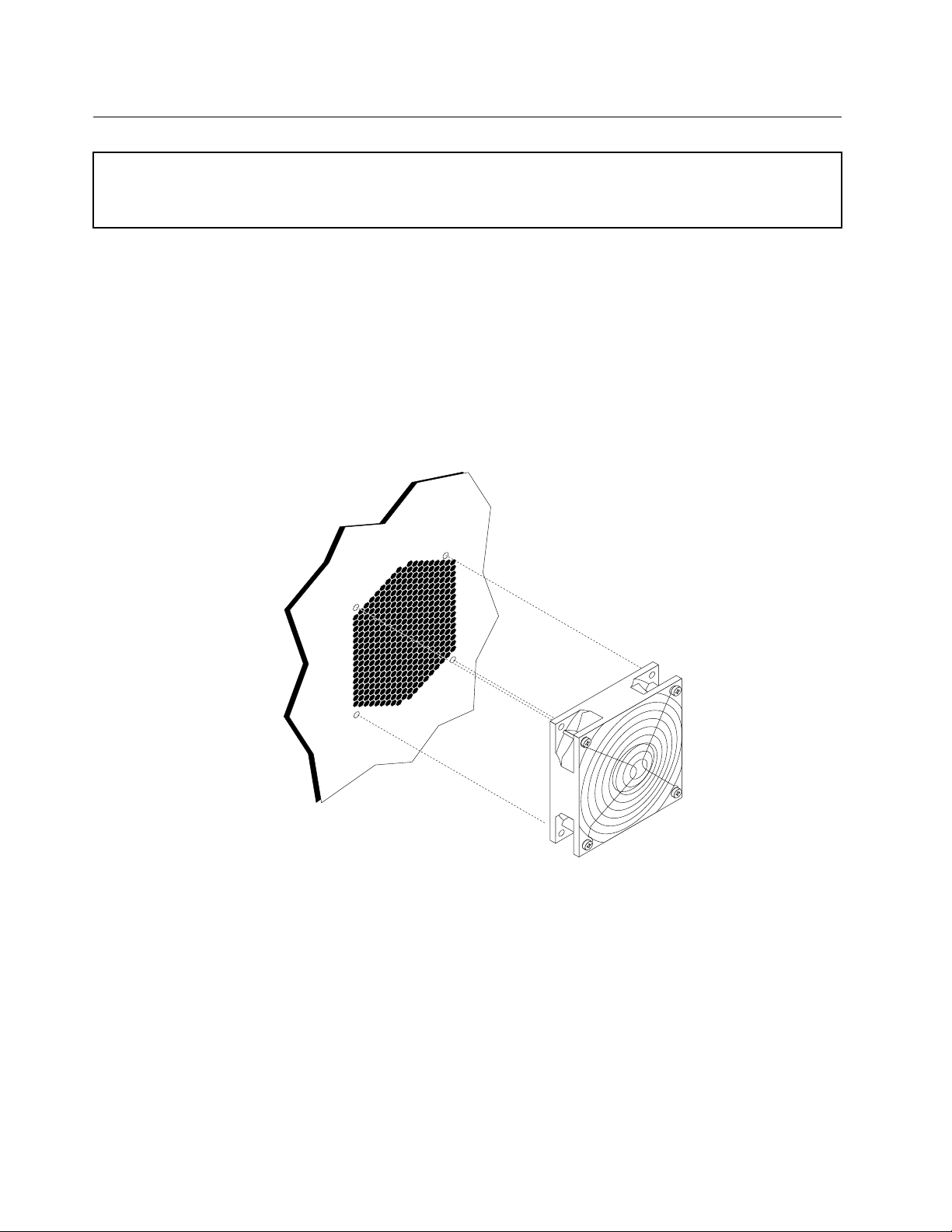
Replacingtherearfanassembly
Attention:Donotopenyourcomputerorattemptanyrepairbeforereadingandunderstandingthe“Importantsafety
information”intheThinkStationSafetyandWarrantyGuidethatcamewithyourcomputer.T oobtainacopyofthe
ThinkStationSafetyandWarrantyGuide,goto:
http://support.lenovo.com
Thissectionprovidesinstructionsonhowtoreplacetherearfanassembly.
Toreplacetherearfanassembly:
1.Removethecomputercover.See“Removingthecomputercover”onpage11.
2.Locatetherearfanassembly.See“Locatingcomponents”onpage7.
3.Disconnecttherearfanassemblycablefromthesystemboard.See“Identifyingpartsonthesystem
board”onpage8.
4.Therearfanassemblyisattachedtothechassisbyfourrubbermounts.Removetherearfanassembly
bygentlypullingitoutofthechassis.
Figure43.Removingtherearfanassembly
5.Installthenewrearfanassemblybyaligningtherubbermountsoftherearfanassemblywiththeholes
onthechassisandpushtherubbermountsthroughtheholes.
6.Pullonthetipsoftherubbermountsuntiltherearfanassemblyisinplace.
7.Connecttherearfanassemblycabletotherearfanconnectoronthesystemboard.
8.GotoChapter4“Completingthepartsreplacement”onpage45.
40ThinkStationHardwareInstallationandReplacementGuide
Page 47

Replacingtheinternalspeaker
Attention:Donotopenyourcomputerorattemptanyrepairbeforereadingandunderstandingthe“Importantsafety
information”intheThinkStationSafetyandWarrantyGuidethatcamewithyourcomputer.T oobtainacopyofthe
ThinkStationSafetyandWarrantyGuide,goto:
http://support.lenovo.com
Thissectionprovidesinstructionsonhowtoreplacetheinternalspeaker.
Toreplacetheinternalspeaker:
1.Removethecomputercover.See“Removingthecomputercover”onpage11.
2.Removethefrontbezel.See“Removingthefrontbezel”onpage12.
3.Locatetheinternalspeaker.See“Locatingcomponents”onpage7.
4.Accesssystemboardcomponents.See“ Accessingsystemboardcomponents”onpage13.Notethe
routeoftheinternalspeakercableandpowerLEDcable,andthendisconnectthesecablesfromthe
systemboard.See“Identifyingpartsonthesystemboard”onpage8.
5.Disengagetheinternalspeakerlockingtab3andslidetheinternalspeaker1downwardstocompletely
removeitfromthechassis.
Figure44.Removingtheinternalspeaker
6.RoutethenewinternalspeakercableandpowerLEDcable,andthenpositionthetwointernalspeaker
latches2intothemetalslotsinthechassis,thenpushtheinternalspeakerupwardsuntilitsnaps
intoposition.
7.ConnecttheinternalspeakercableandthepowerLEDcabletothesystemboard.See“Identifying
partsonthesystemboard”onpage8
.
Chapter3.Installingoptionsandreplacinghardware41
Page 48

8.Reinstalltheharddiskdrivefanbracketifremoved.
9.Reinstallthefrontbezel.
10.GotoChapter4“Completingthepartsreplacement”onpage45.
Replacingthekeyboard
Attention:Donotopenyourcomputerorattemptanyrepairbeforereadingandunderstandingthe“Importantsafety
information”intheThinkStationSafetyandWarrantyGuidethatcamewithyourcomputer.T oobtainacopyofthe
ThinkStationSafetyandWarrantyGuide,goto:
http://support.lenovo.com
Thissectionprovidesinstructionsonhowtoreplaceakeyboard.
Toreplaceakeyboard:
1.Locatethekeyboardconnector.See“Locatingcontrolsandconnectorsonthefrontofyourcomputer”
onpage4or“Locatingconnectorsontherearofyourcomputer”onpage5.
Figure45.Keyboardconnector
2.Disconnectthefailingkeyboardcablefromthecomputer.
3.ConnectthenewkeyboardcabletooneoftheUSBconnectors.
4.GotoChapter4“Completingthepartsreplacement”onpage45.
Replacingthemouse
Attention:Donotopenyourcomputerorattemptanyrepairbeforereadingandunderstandingthe“Importantsafety
information”intheThinkStationSafetyandWarrantyGuidethatcamewithyourcomputer.T oobtainacopyofthe
ThinkStationSafetyandWarrantyGuide,goto:
http://support.lenovo.com
Thissectionprovidesinstructionsonhowtoreplaceamouse.
Toreplaceamouse:
1.Locatetheconnectorforthemouse.See“Locatingcontrolsandconnectorsonthefrontofyour
computer”onpage4or“Locatingconnectorsontherearofyourcomputer”onpage5.
42ThinkStationHardwareInstallationandReplacementGuide
Page 49

Figure46.Mouseconnector
2.Disconnectthefailingmousecablefromthecomputer.
3.ConnectthenewmousecabletooneoftheUSBconnectors.
4.GotoChapter4“Completingthepartsreplacement”onpage45.
Chapter3.Installingoptionsandreplacinghardware43
Page 50

44ThinkStationHardwareInstallationandReplacementGuide
Page 51

Chapter4.Completingthepartsreplacement
Aftercompletingallpartsreplacements,replacethecomputercoverandreconnectcables,including
telephonelinesandpowercords.Dependingonthepartsreplaced,youmightneedtoconrmtheupdated
informationintheSetupUtilityprogram.Referto"UsingtheSetupUtility"intheThinkStationUserGuide
forthisproduct.
Tocompletethepartsreplacement:
1.Ensurethatallcomponentshavebeenreassembledcorrectlyandthatnotoolsorloosescrewsareleft
insideyourcomputer.See“Locatingcomponents”onpage7forthelocationofvariouscomponents.
2.Makesurethatthecablesareroutedcorrectly.
Important:Correctlyrouteallpowersupplycables.Keepcablesclearofthehingesandsidesof
thecomputerchassis.
3.Replacethecomputercover.
a.Alignthecoverwiththechassis.
b.Closethecover.
c.Engagethecoverlatch.
d.Checktobesurethecoverislatched.
4.Ifacoverlockisinstalled,lockthecover.
5.Reconnecttheexternalcablesandpowercordstothecomputer.See“Locatingconnectorsontherear
ofyourcomputer”onpage5.
6.T oupdateyourconguration,see“UsingtheSetupUtility”intheThinkStationUserGuide.
Note:Inmostareasoftheworld,LenovorequiresthereturnofthedefectiveCRU.Informationaboutthiswill
comewiththeCRUorwillcomeafewdaysaftertheCRUarrives.
Obtainingdevicedrivers
Youcanobtaindevicedriversforoperatingsystemsthatarenotpreinstalledat:
http://support.lenovo.com
Installationinstructionsareprovidedinreadmeleswiththedevice-driverles.
©CopyrightLenovo2009,2011
45
Page 52

46ThinkStationHardwareInstallationandReplacementGuide
Page 53

Chapter5.Securityfeatures
Tohelppreventhardwaretheftandunauthorizedaccesstoyourcomputer,severalsecuritylockoptionsare
available.Inadditiontoaphysicallock,unauthorizeduseofyourcomputercanbepreventedbyasoftware
lockthatlocksthekeyboarduntilacorrectpasswordistypedin.
Makesurethatanysecuritycablesthatyouinstalldonotinterferewithothercomputercables.
Lockingdevices
Thissectiondescribesthedifferentkindsoflockingdevicesforthisproduct.
Figure47.Lockingdevices
Akeylock1comeswiththisproductbuiltintothesidecover.Thekeys2forthesidecoverareattachedto
therearofthemachine.Forsecurity,storethekeysinasecureplacewhenyouarenotusingthem.
Anoptionalpadlockwitha5mm(0.20inch)shacklecanbeusedtosecuretheproductcoverusedthe
padlockhasp
Anoptionalintegratedcablelock4(sometimesreferredtoastheKensingtonlock)canbeusedtosecure
yourcomputertoadesk,table,orothernon-permanentxture.Thecablelockattachestoasecurityslotat
therearofyourcomputerandisoperatedwithakey.Thecablelockalsolocksthebuttonsusedtoopen
©CopyrightLenovo2009,2011
3.
47
Page 54

thecomputercover.Thisisthesametypeoflockusedwithmanynotebookcomputers.Y oucanordera
securitycabledirectlyfromLenovobysearchingonKensingtonat:
http://support.lenovo.com
Passwordprotection
Todeterunauthorizeduseofyourcomputer,youcanusetheSetupUtilityprogramtosetapassword.When
youturnonyourcomputer,youarepromptedtotypethepasswordtounlockthekeyboardfornormaluse.
Whattodonext:
•T oworkwithanotheroption,gototheappropriatesection.
•T ocompletetheinstallation,gotoChapter4“Completingthepartsreplacement”onpage45.
Erasingalostorforgottenpassword(clearingCMOS)
Thissectioncontainsinstructionsonerasingsomelostorforgottenpasswords,suchasauserpassword.
Toeraseaforgottenpassword:
1.Removethecomputercover.See“Removingthecomputercover”onpage11.
2.Accessthesystemboard.See“Accessingsystemboardcomponents”onpage13.
3.LocatetheClearCMOS/Recoveryjumperonthesystemboard.See“Identifyingpartsonthesystem
board”onpage8.
4.Movethejumperfromthestandardposition(pin1andpin2)tothemaintenanceorcongureposition
(pin2andpin3).
5.Reinstalltheadaptercardifremoved.
6.Replacethecomputercoverandconnectthepowercord.SeeChapter4“Completingtheparts
replacement”onpage45.
7.Restartthecomputer,leaveitonforapproximately10seconds.Turnoffthecomputerbyholdingthe
powerswitchforapproximatelyveseconds.Thecomputerwillturnoff.
8.Repeatsteps1through3.
9.MovetheClearCMOS/Recoveryjumperbacktothestandardposition(pin1andpin2).
10.Reinstalltheadaptercardifremoved.
11.Replacethecomputercoverandconnectthepowercord.SeeChapter4“Completingtheparts
replacement”onpage45
.
48ThinkStationHardwareInstallationandReplacementGuide
Page 55

AppendixA.Systemmemoryspeed
TheIntelXeonmicroprocessorfamiliescompatiblewiththisThinkStationcomputerfeatureanintegrated
memorycontroller,whichprovidesthemicroprocessorwithdirectaccesstothesystemmemory.Because
ofthisdesign,thesystemmemoryspeedwillbedeterminedbyanumberoffactors,includingthe
microprocessormodelandthetype,speed,size(capacity),andnumberofDIMMsinstalled.Refertothe
followingtablefortheinformationonthesupportedsystemmemoryspeedforyourowncomputermodel.
Table1.DIMMtypeandspeed:PC3-10600U
NumberofDIMMs
DIMMsize(capacity)
1GB,2GB,4GB
installedper
microprocessorbank
1to3
4to6
MicroprocessormodelMemoryfrequency
IntelXeonE5502,E5503,
E5504,E5506,E5507
IntelXeonE5603,E5606,
E5607,E5520,E5530,
E5540,E5620,E5630,
E5640,X5647
IntelXeonE5645,E5649,
X5550,X5560,X5570,
X5650,X5660,X5667,
X5670,X5672,X5675,
X5677,X5680,X5687,
X5690,W5580,W5590
IntelXeonE5502,E5503,
E5504,E5506,E5507
IntelXeonE5603,E5606,
E5607,E5520,E5530,
E5540,E5620,E5630,
E5640,X5550,X5560,
X5570,X5647,W5580,
W5590
IntelXeonE5645,E5649,
X5650,X5660,X5667,
X5670,X5672,X5675,
X5677,X5680,X5687,
X5690
800MHz
1066MHz
1333MHz
800MHz
1066MHz
1333MHz
Table2.DIMMtypeandspeed:PC3-8500U
DIMMsize(capacity)
1GB,2GB,4GB
©CopyrightLenovo2009,2011
NumberofDIMMs
installedper
microprocessorbank
1to6
MicroprocessormodelMemoryfrequency
IntelXeonE5502,E5503,
E5504,E5506,E5507
IntelXeonE5603,E5606,
E5607,E5520,E5530,
E5540,E5620,E5630,
E5640,E5645,X5647,
E5649,X5550,X5560,
X5570,X5650,X5660,
X5667,X5670,X5672,
X5675,X5677,X5680,
800MHz
1066MHz
49
Page 56

Table2.DIMMtypeandspeed:PC3-8500U(continued)
DIMMsize(capacity)
Table3.DIMMtypeandspeed:PC3-10600R
DIMMsize(capacity)
1GB,2GB,4GB,8GB
NumberofDIMMs
installedper
microprocessorbank
NumberofDIMMs
installedper
microprocessorbank
1to3
4to6
MicroprocessormodelMemoryfrequency
X5687,X5690,W5580,
W5590
MicroprocessormodelMemoryfrequency
IntelXeonE5502,E5503,
E5504,E5506,E5507
IntelXeonE5603,E5606,
E5607,E5520,E5530,
E5540,E5620,E5630,
E5640,X5647
IntelXeonE5645,E5649,
X5550,X5560,X5570,
X5650,X5660,X5667,
X5670,X5672,X5675,
X5677,X5680,X5687,
X5690,W5580,W5590
IntelXeonE5502,E5503,
E5504,E5506,E5507
IntelXeonE5603,E5606,
E5607,E5520,E5530,
E5540,E5620,E5630,
E5640,X5550,X5560,
X5570,X5647,W5580,
W5590
IntelXeonE5645,E5649,
X5650,X5660,X5667,
X5670,X5672,X5675,
X5677,X5680,X5687,
X5690
800MHz
1066MHz
1333MHz
800MHz
1066MHz
1333MHz
Table4.DIMMtypeandspeed:PC3-8500R
NumberofDIMMs
DIMMsize(capacity)
1GB,2GB,4GB
installedper
microprocessorbank
1to6
50ThinkStationHardwareInstallationandReplacementGuide
MicroprocessormodelMemoryfrequency
IntelXeonE5502,E5503,
E5504,E5506,E5507
IntelXeonE5603,E5606,
E5607,E5520,E5530,
E5540,E5620,E5630,
E5640,X5647,E5645,
E5649,X5550,X5560,
X5570,X5650,X5660,
X5667,X5670,X5672,
X5675,X5677,X5680,
X5687,X5690,W5580,
W5590
800MHz
1066MHz
Page 57

Table4.DIMMtypeandspeed:PC3-8500R(continued)
DIMMsize(capacity)
8GB,16GB
NumberofDIMMs
installedper
microprocessorbank
1to3
4to6
MicroprocessormodelMemoryfrequency
IntelXeonE5502,E5503,
E5504,E5506,E5507
IntelXeonE5603,E5606,
E5607,E5520,E5530,
E5540,E5620,E5630,
E5640,X5647,E5645,
E5649,X5550,X5560,
X5570,X5650,X5660,
X5667,X5670,X5672,
X5675,X5677,X5680,
X5687,X5690,W5580,
W5590
IntelXeonE5502,E5503,
E5504,E5506,E5507,
E5603,E5606,E5607,
E5520,E5530,E5540,
E5620,E5630,E5640,
X5647,E5645,E5649,
X5550,X5560,X5570,
X5650,X5660,X5667,
X5670,X5672,X5675,
X5677,X5680,X5687,
X5690,W5580,W5590
800MHz
1066MHz
800MHz
AppendixA.Systemmemoryspeed51
Page 58

52ThinkStationHardwareInstallationandReplacementGuide
Page 59

AppendixB.Notices
Lenovomaynotoffertheproducts,services,orfeaturesdiscussedinthisdocumentinallcountries.Consult
yourlocalLenovorepresentativeforinformationontheproductsandservicescurrentlyavailableinyour
area.AnyreferencetoaLenovoproduct,program,orserviceisnotintendedtostateorimplythatonlythat
Lenovoproduct,program,orservicemaybeused.Anyfunctionallyequivalentproduct,program,orservice
thatdoesnotinfringeanyLenovointellectualpropertyrightmaybeusedinstead.However,itistheuser's
responsibilitytoevaluateandverifytheoperationofanyotherproduct,program,orservice.
Lenovomayhavepatentsorpendingpatentapplicationscoveringsubjectmatterdescribedinthis
document.Thefurnishingofthisdocumentdoesnotgiveyouanylicensetothesepatents.Y oucansend
licenseinquiries,inwriting,to:
Lenovo(UnitedStates),Inc.
1009ThinkPlace-BuildingOne
Morrisville,NC27560
U.S.A.
Attention:LenovoDirectorofLicensing
LENOVOPROVIDESTHISPUBLICATION“ASIS”WITHOUTWARRANTYOFANYKIND,EITHEREXPRESS
ORIMPLIED,INCLUDING,BUTNOTLIMITEDTO,THEIMPLIEDWARRANTIESOFNON-INFRINGEMENT,
MERCHANTABILITYORFITNESSFORAPARTICULARPURPOSE.Somejurisdictionsdonotallow
disclaimerofexpressorimpliedwarrantiesincertaintransactions,therefore,thisstatementmaynotapply
toyou.
Thisinformationcouldincludetechnicalinaccuraciesortypographicalerrors.Changesareperiodically
madetotheinformationherein;thesechangeswillbeincorporatedinneweditionsofthepublication.
Lenovomaymakeimprovementsand/orchangesintheproduct(s)and/ortheprogram(s)describedinthis
publicationatanytimewithoutnotice.
Theproductsdescribedinthisdocumentarenotintendedforuseinimplantationorotherlifesupport
applicationswheremalfunctionmayresultininjuryordeathtopersons.Theinformationcontainedinthis
documentdoesnotaffectorchangeLenovoproductspecicationsorwarranties.Nothinginthisdocument
shalloperateasanexpressorimpliedlicenseorindemnityundertheintellectualpropertyrightsofLenovo
orthirdparties.Allinformationcontainedinthisdocumentwasobtainedinspecicenvironmentsandis
presentedasanillustration.Theresultobtainedinotheroperatingenvironmentsmayvary.
Lenovomayuseordistributeanyoftheinformationyousupplyinanywayitbelievesappropriatewithout
incurringanyobligationtoyou.
Anyreferencesinthispublicationtonon-LenovoWebsitesareprovidedforconvenienceonlyanddonotin
anymannerserveasanendorsementofthoseWebsites.ThematerialsatthoseWebsitesarenotpartof
thematerialsforthisLenovoproduct,anduseofthoseWebsitesisatyourownrisk.
Anyperformancedatacontainedhereinwasdeterminedinacontrolledenvironment.Therefore,theresult
obtainedinotheroperatingenvironmentsmayvarysignicantly.Somemeasurementsmayhavebeen
madeondevelopment-levelsystemsandthereisnoguaranteethatthesemeasurementswillbethesame
ongenerallyavailablesystems.Furthermore,somemeasurementsmayhavebeenestimatedthrough
extrapolation.Actualresultsmayvary.Usersofthisdocumentshouldverifytheapplicabledatafortheir
specicenvironment.
©CopyrightLenovo2009,2011
53
Page 60

Televisionoutputnotice
Thefollowingnoticeappliestomodelsthathavethefactory-installedtelevision-outputfeature.
ThisproductincorporatescopyrightprotectiontechnologythatisprotectedbymethodclaimsofcertainU.S.
patentsandotherintellectualpropertyrightsownedbyMacrovisionCorporationandotherrightsowners.
UseofthiscopyrightprotectiontechnologymustbeauthorizedbyMacrovisionCorporation,andisintended
forhomeandotherlimitedviewingusesonlyunlessotherwiseauthorizedbyMacrovisionCorporation.
Reverseengineeringordisassemblyisprohibited.
Trademarks
ThefollowingtermsaretrademarksofLenovointheUnitedStates,othercountries,orboth:
Lenovo
TheLenovologo
ThinkStation
Othercompany,product,orservicenamesmaybetrademarksorservicemarksofothers.
54ThinkStationHardwareInstallationandReplacementGuide
Page 61

Index
A
adaptercards27
installing27
adaptercards,replacing30
audioline-inconnector6
audioline-outconnector6
B
battery,replacing22
bay4drive,installing18
C
cablelock,security47
cardreader,replacing35
CMOS,clearing48
components,accessingsystemboard13
components,internal7
computercover
removing11
connectordescription6
connectors
front4
rear5
CRU
completingtheinstallation45
D
devicedrivers45
devices,handlingstatic-sensitive3
diskettedrive,replacing35
drivers,device45
drives
bays16
internal15
specications16
E
eSAT Aconnector6
Ethernetconnector6
externaloptions,installing11
heatsinkandfanassembly,replacing31
I
IEEE1394connector6
importantsafetyinformation1
informationresources3
installing
bay4drive18
internaloptions11
installingoptions
adaptercards27
internaldrives15
memory25
securityfeatures47
internaloptions,installing11
internalspeaker,replacing41
K
keyboard,replacing42
L
locatingcomponents7
M
Microphoneconnector6
mouse,replacing42
N
notice,televisionoutput54
notices53
O
opticaldrive,replacing34
OpticalSPDIFinconnector6
OpticalSPDIFoutconnector6
options,installinginternaldrives15
outputnotice,television54
overview3
F
frontconnectors4
frontpanelconnectorassembly,replacing37
H
harddiskdrivefanassembly,replacing38
harddiskdrive,replacing33
©CopyrightLenovo2009,2011
P
partsreplacement,completing45
password
erasing48
lostorforgotten48
passwordprotection48
powersupply,replacing23
protection,password48
55
Page 62

R
rearconnectors5
rearfanassembly,replacing40
removingthecomputercover11
replacing
adaptercards30
battery22
harddiskdrive33
heatsinkandfanassembly31
internalspeaker41
resources,information3
S
safetyinformation1
security
cablelock47
features,installing47
serialport6
static-sensitivedevices,handling3
systemboard
components,accessing13
connectors8
identifyingparts8
location8
T
televisionoutputnotice54
trademarks54
U
USBconnector6
56ThinkStationHardwareInstallationandReplacementGuide
Page 63

Page 64

PartNumber:53Y4276
PrintedinUSA
(1P)P/N:53Y4276
*53Y4276*
 Loading...