

Page 1

HardwareMaintenanceManual
LenovoV570,B570,andB570e
Page 2

Note:Beforeusingthisinformationandtheproductitsupports,besuretoreadthegeneralinformation
underAppendixA“Notices”onpage87.
SecondEdition(January2012)
©CopyrightLenovo2012.
LIMITEDANDRESTRICTEDRIGHTSNOTICE:IfdataorsoftwareisdeliveredpursuantaGeneralServicesAdministration
“GSA”contract,use,reproduction,ordisclosureissubjecttorestrictionssetforthinContractNo.GS-35F-05925.
Page 3

Contents
Aboutthismanual...........iii
Chapter1.Safetyinformation......1
Generalsafety................1
Electricalsafety...............2
Safetyinspectionguide............3
Handlingdevicesthataresensitivetoelectrostatic
discharge..................3
Groundingrequirements............4
Safetynotices(multilingualtranslations)......4
Lasercompliancestatement(multilingual
translations)................19
Chapter2.Importantservice
information..............27
StrategyforreplacingFRUs.........27
Strategyforreplacingaharddiskdrive...27
Importantnoticeforreplacingasystem
board................28
ImportantinformationaboutreplacingRoHS
compliantFRUs..............28
Chapter3.Generalcheckout.....29
Whattodorst..............29
Powersystemcheckout...........30
Checkingtheacpoweradapter......30
Checkingoperationalcharging......31
Checkingthebatterypack........31
Chapter6.FRUreplacement
notices................43
Screwnotices...............43
Chapter7.Removingandreplacinga
FRU..................45
1010Batterypack.............46
1020Dummycard.............47
1030Harddiskdrive(HDD)/memorymodule/mini
PCIExpressCardslotcompartmentcover....47
1040Harddiskdrive............48
1050Opticaldrive.............49
1060Memorymodule............50
1070PCIExpressMiniCardforwireless
LAN/WAN................51
1080Keyboard..............53
1090Keyboardbezel............54
1100Systemboardassembly.........56
1110LCDunit...............58
1120Fanassemblyandheatsinkassembly...60
1130CPU................62
1140Basecover,speakers,andbluetooth
daughtercard...............63
1150LCDfrontbezel............66
1160LCDpanel,LCDcable,andhinges....67
1170Integratedcamera...........69
1180AntennaassemblyandLCDcover.....70
Chapter4.Relatedservice
information..............33
RestoringthefactorycontentsbyusingOneKey
Recovery.................33
Passwords................33
Power-onpassword...........33
Supervisorpassword..........34
Powermanagement............34
Screenblankmode...........34
Sleep(standby)mode..........34
Hibernationmode...........34
Chapter5.LenovoV570,B570,and
B570e.................37
Specications...............37
Statusindicators..............39
Fnkeycombinations............40
©CopyrightLenovo2012
Chapter8.Locations.........73
Frontview................73
Right-sideview..............74
Bottomandleft-sideview..........74
Chapter9.Partslist..........75
Overall..................76
LCDFRUs................80
Keyboard.................81
Miscellaneousparts............82
acpoweradapters.............83
Powercords...............83
AppendixA.Notices..........87
Trademarks................88
i
Page 4

iiHardwareMaintenanceManual
Page 5
Aboutthismanual
ThismanualcontainsserviceandreferenceinformationforthefollowingLenovo
Product
LenovoV5701066,20092
LenovoB5701068,20093
LenovoB570e5215,20173
Machinetype(MT)
®
products.
Usethismanualtotroubleshootproblems.
Themanualisdividedintothefollowingsections:
•Thecommonsectionsprovidegeneralinformation,guidelines,andsafetyinformationrequiredfor
servicingcomputers.
•Theproduct-specicsectionincludesservice,reference,andproduct-specicpartsinformation.
Important:
ThismanualisintendedonlyfortrainedservicetechnicianswhoarefamiliarwithLenovoproducts.Use
thismanualtotroubleshootproblemseffectively.
BeforeservicingaLenovoproduct,besuretoreadalltheinformationunderChapter1“Safety
information”onpage1
andChapter2“Importantserviceinformation”onpage27.
©CopyrightLenovo2012
iii
Page 6

ivHardwareMaintenanceManual
Page 7

Chapter1.Safetyinformation
Thischapterpresentsfollowingsafetyinformationthatyouneedtobefamiliarwithbeforeyouservicea
LenovoNotebook.
•“Generalsafety”onpage1
•“Electricalsafety”onpage2
•“Safetyinspectionguide”onpage3
•“Handlingdevicesthataresensitivetoelectrostaticdischarge”onpage3
•“Groundingrequirements”onpage4
•“Safetynotices(multilingualtranslations)”onpage4
•“Lasercompliancestatement(multilingualtranslations)”onpage19
Generalsafety
Followtheserulestoensuregeneralsafety:
•Observegoodhousekeepingintheareaofthemachinesduringandaftermaintenance.
•Whenliftinganyheavyobject:
1.Makesurethatyoucanstandsafelywithoutslipping.
2.Distributetheweightoftheobjectequallybetweenyourfeet.
3.Useaslowliftingforce.Nevermovesuddenlyortwistwhenyouattempttolift.
4.Liftbystandingorbypushingupwithyourlegmuscles;thisactionremovesthestrainfromthe
musclesinyourback.Donotattempttoliftanyobjectthatweighsmorethan16kg(35lb)orthatyou
thinkistooheavyforyou.
•Donotperformanyactionthatcauseshazardstothecustomer,orthatmakestheequipmentunsafe.
•Beforeyoustartthemachine,makesurethatotherservicetechniciansandthecustomer'spersonnelare
notinahazardousposition.
•Placeremovedcoversandotherpartsinasafeplace,awayfromallpersonnel,whileyouareservicing
themachine.
•Keepyourtoolcaseawayfromwalkareassothatotherpeoplewillnottripoverit.
•Donotwearlooseclothingthatcanbetrappedinthemovingpartsofamachine.Makesurethatyour
sleevesarefastenedorrolledupaboveyourelbows.Ifyourhairislong,fastenit.
•Inserttheendsofyournecktieorscarfinsideclothingorfastenitwithanonconductiveclip,about8
centimeters(3inches)fromtheend.
•Donotwearjewelry,chains,metal-frameeyeglasses,ormetalfastenersforyourclothing,becausemetal
objectsaregoodelectricalconductors.
•Wearsafetyglasseswhenyouarehammering,drilling,soldering,cuttingwire,attachingsprings,using
solvents,orworkinginanyotherconditionsthatmightbehazardoustoyoureyes.
•Afterservice,reinstallallsafetyshields,guards,labels,andgroundwires.Replaceanysafetydevice
thatiswornordefective.
•Reinstallallcoverscorrectlybeforereturningthemachinetothecustomer.
•Fanlouversonthemachinehelptopreventoverheatingofinternalcomponents.Donotobstructfan
louversorcoverthemwithlabelsorstickers.
©CopyrightLenovo2012
1
Page 8

Electricalsafety
Observethefollowingruleswhenworkingonelectricalequipment.
Important:
Useonlyapprovedtoolsandtestequipment.Somehandtoolshavehandlescoveredwithasoftmaterial
thatdoesnotinsulateyouwhenworkingwithliveelectricalcurrents.
Manycustomershave,neartheirequipment,rubberoormatsthatcontainsmallconductivebersto
decreaseelectrostaticdischarges.Donotusethistypeofmattoprotectyourselffromelectricalshock.
•Findtheroomemergencypower-off(EPO)switch,disconnectingswitch,orelectricaloutlet.Ifanelectrical
accidentoccurs,youcanthenoperatetheswitchorunplugthepowercordquickly.
•Donotworkaloneunderhazardousconditionsornearequipmentthathashazardousvoltages.
•Disconnectallpowerbefore:
–Performingamechanicalinspection
–Workingnearpowersupplies
–Removingorinstallingmainunits
•Beforeyoustarttoworkonthemachine,unplugthepowercord.Ifyoucannotunplugit,askthecustomer
topower-offthewallboxthatsuppliespowertothemachine,andtolockthewallboxintheoffposition.
•Ifyouneedtoworkonamachinethathasexposedelectricalcircuits,observethefollowingprecautions:
–Ensurethatanotherperson,familiarwiththepower-offcontrols,isnearyou.
Attention:Anotherpersonmustbetheretoswitchoffthepower,ifnecessary.
–Useonlyonehandwhenworkingwithpowered-onelectricalequipment;keeptheotherhandinyour
pocketorbehindyourback.
Attention:Anelectricalshockcanoccuronlywhenthereisacompletecircuit.Byobservingtheabove
rule,youmaypreventacurrentfrompassingthroughyourbody.
–Whenusingtesters,setthecontrolscorrectlyandusetheapprovedprobeleadsandaccessoriesfor
thattester.
–Standonsuitablerubbermats(obtainedlocally,ifnecessary)toinsulateyoufromgroundssuchas
metaloorstripsandmachineframes.
Observethespecialsafetyprecautionswhenyouworkwithveryhighvoltages;Instructionsforthese
precautionsareinthesafetysectionsofmaintenanceinformation.Useextremecarewhenmeasuring
highvoltages.
•Regularlyinspectandmaintainyourelectricalhandtoolsforsafeoperationalcondition.
•Donotusewornorbrokentoolsandtesters.
•Neverassumethatpowerhasbeendisconnectedfromacircuit.First,checkthatithasbeenpoweredoff.
•Alwayslookcarefullyforpossiblehazardsinyourworkarea.Examplesofthesehazardsaremoistoors,
nongroundedpowerextensioncables,powersurges,andmissingsafetygrounds.
•Donottouchliveelectricalcircuitswiththereectivesurfaceofaplasticdentalmirror.Thesurfaceis
conductive;suchtouchingcancausepersonalinjuryandmachinedamage.
•Donotservicethefollowingpartswiththepoweronwhentheyareremovedfromtheirnormaloperating
placesinamachine:
–Powersupplyunits
–Pumps
–Blowersandfans
–Motorgenerators
–Similarunitstolistedabove
Thispracticeensurescorrectgroundingoftheunits.
•Ifanelectricalaccidentoccurs:
2HardwareMaintenanceManual
Page 9

–Caution:donotbecomeavictimyourself.
–Switchoffpower.
–Sendanotherpersontogetmedicalaid.
Safetyinspectionguide
Thepurposeofthisinspectionguideistoassistyouinidentifyingpotentiallyunsafeconditions.Aseach
machinewasdesignedandbuilt,requiredsafetyitemswereinstalledtoprotectusersandservicetechnicians
frominjury.Thisguideaddressesonlythoseitems.Y oushouldusegoodjudgmenttoidentifypotential
safetyhazardsduetoattachmentofnon-Lenovofeaturesoroptionsnotcoveredbythisinspectionguide.
Ifanyunsafeconditionsarepresent,youmustdeterminehowserioustheapparenthazardcouldbeand
whetheryoucancontinuewithoutrstcorrectingtheproblem.
Considertheseconditionsandthesafetyhazardstheypresent:
•Electricalhazards,especiallyprimarypower(primaryvoltageontheframecancauseseriousorfatal
electricalshock)
•Explosivehazards,suchasadamagedCRTfaceorabulgingcapacitor
•Mechanicalhazards,suchaslooseormissinghardware
Todeterminewhetherthereareanypotentiallyunsafeconditions,usethefollowingchecklistatthebeginning
ofeveryservicetask.Beginthecheckswiththepoweroff,andthepowercorddisconnected.
Checklist:
1.Checkexteriorcoversfordamage(loose,broken,orsharpedges).
2.Poweroffthecomputer.Disconnectthepowercord.
3.Checkthepowercordfor:
a.Athird-wiregroundconnectoringoodcondition.Useametertomeasurethird-wireground
continuityfor0.1ohmorlessbetweentheexternalgroundpinandtheframeground.
b.Thepowercordshouldbethetypespeciedinthepartslist.
c.Insulationmustnotbefrayedorworn.
4.Checkforcrackedorbulgingbatteries.
5.Removethecover.
6.Checkforanyobviousnon-Lenovoalterations.Usegoodjudgmentastothesafetyofanynon-Lenovo
alterations.
7.Checkinsidetheunitforanyobviousunsafeconditions,suchasmetallings,contamination,wateror
otherliquids,orsignsofreorsmokedamage.
8.Checkforworn,frayed,orpinchedcables.
9.Checkthatthepower-supplycoverfasteners(screwsorrivets)havenotbeenremovedortamperedwith.
Handlingdevicesthataresensitivetoelectrostaticdischarge
Anycomputerpartcontainingtransistorsorintegratedcircuits(ICs)shouldbeconsideredsensitiveto
electrostaticdischarge(ESD.)ESDdamagecanoccurwhenthereisadifferenceinchargebetweenobjects.
ProtectagainstESDdamagebyequalizingthechargesothatthemachine,thepart,theworkmat,andthe
personhandlingthepartareallatthesamecharge.
Notes:
1.Useproduct-specicESDprocedureswhentheyexceedtherequirementsnotedhere.
Chapter1.Safetyinformation3
Page 10
2.MakesurethattheESDprotectivedevicesyouusehavebeencertied(ISO9000)asfullyeffective.
WhenhandlingESD-sensitiveparts:
•Keepthepartsinprotectivepackagesuntiltheyareinsertedintotheproduct.
•Avoidcontactwithotherpeople.
•Wearagroundedwriststrapagainstyourskintoeliminatestaticonyourbody.
•Preventthepartfromtouchingyourclothing.Mostclothingisinsulativeandretainsachargeevenwhen
youarewearingawriststrap.
•Useagroundedworkmattoprovideastatic-freeworksurface.Thematisespeciallyusefulwhen
handlingESD-sensitivedevices.
•Selectagroundingsystem,suchasthoselistedbelow,toprovideprotectionthatmeetsthespecic
servicerequirement.
Note:TheuseofagroundingsystemtoguardagainstESDdamageisdesirablebutnotnecessary.
–AttachtheESDgroundcliptoanyframeground,groundbraid,orgreen-wireground.
–Whenworkingonadouble-insulatedorbattery-operatedsystem,useanESDcommongroundor
referencepoint.Y oucanusecoaxorconnector-outsideshellsonthesesystems.
–Usetheroundgroundprongoftheacplugonac-operatedcomputers.
Groundingrequirements
Electricalgroundingofthecomputerisrequiredforoperatorsafetyandcorrectsystemfunction.Proper
groundingoftheelectricaloutletcanbeveriedbyacertiedelectrician.
Safetynotices(multilingualtranslations)
Thesafetynoticesinthissectionareprovidedinthefollowinglanguages:
•English
•Arabic
•BrazilianPortuguese
•French
•German
•Hebrew
•Japanese
•Korean
•Spanish
•T raditionalChinese
DANGER
DANGER
4HardwareMaintenanceManual
Page 11
DANGER
DANGER
DANGER
DANGER
DANGER
Chapter1.Safetyinformation5
Page 12
DANGER
6HardwareMaintenanceManual
Page 13

Chapter1.Safetyinformation7
Page 14
PERIGO
PERIGO
PERIGO
PERIGO
PERIGO
PERIGO
8HardwareMaintenanceManual
Page 15
PERIGO
PERIGO
DANGER
DANGER
DANGER
Chapter1.Safetyinformation9
Page 16
DANGER
DANGER
DANGER
DANGER
DANGER
VORSICHT
10HardwareMaintenanceManual
Page 17
VORSICHT
VORSICHT
VORSICHT
VORSICHT
Chapter1.Safetyinformation11
Page 18
VORSICHT
VORSICHT
VORSICHT
12HardwareMaintenanceManual
Page 19
Chapter1.Safetyinformation13
Page 20
14HardwareMaintenanceManual
Page 21
Chapter1.Safetyinformation15
Page 22
16HardwareMaintenanceManual
Page 23
Chapter1.Safetyinformation17
Page 24
18HardwareMaintenanceManual
Page 25
Lasercompliancestatement(multilingualtranslations)
Thelasercompliancestatementsinthissectionareprovidedinthefollowinglanguages:
•English
•Arabic
•BrazilianPortuguese
•French
•German
•Hebrew
•Japanese
•Korean
•Spanish
•T raditionalChinese
Chapter1.Safetyinformation19
Page 26
20HardwareMaintenanceManual
Page 27
Chapter1.Safetyinformation21
Page 28
22HardwareMaintenanceManual
Page 29
Chapter1.Safetyinformation23
Page 30

24HardwareMaintenanceManual
Page 31

Chapter1.Safetyinformation25
Page 32

26HardwareMaintenanceManual
Page 33

Chapter2.Importantserviceinformation
Thischapterpresentsfollowingimportantserviceinformationthatappliestoallmachinetypessupportedby
thismanual:
•“StrategyforreplacingFRUs”onpage27
–“Strategyforreplacingaharddiskdrive”onpage27
–“Importantnoticeforreplacingasystemboard”onpage28
•“ImportantinformationaboutreplacingRoHScompliantFRUs”onpage28
Important:BIOSanddevicedriverxesarecustomer-installable.TheBIOSanddevicedriversareavailable
at
http://consumersupport.lenovo.com/
StrategyforreplacingFRUs
Beforereplacingparts:
Makesurethatallsoftwarexes,drivers,andBIOSdownloadsareinstalledbeforereplacinganyFRUs
listedinthismanual.
Afterasystemboardisreplaced,ensurethatthelatestBIOSisloadedtothesystemboardbefore
completingtheserviceaction.
Todownloadsoftwarexes,drivers,andBIOS,doasfollows:
1.Gotohttp://consumersupport.lenovo.com/.
2.EnteraserialnumberorselectaproductoruseLenovosmartdownloading.
3.SelecttheBIOS/Driver/Applications.
4.Followthedirectionsonthescreenandinstallthenecessarysoftware.
UsethefollowingstrategytopreventunnecessaryexpenseforreplacingandservicingFRUs:
•IfyouareinstructedtoreplaceaFRUbutthereplacementdoesnotcorrecttheproblem,reinstall
theoriginalFRUbeforeyoucontinue.
•Somecomputershavebothaprocessorboardandasystemboard.Ifyouareinstructedtoreplaceeither
theprocessorboardorthesystemboard,andreplacingoneofthemdoesnotcorrecttheproblem,
reinstallthatboard,andthenreplacetheotherone.
•IfanadapteroradeviceconsistsofmorethanoneFRU,anyoftheFRUsmaybethecauseoftheerror.
Beforereplacingtheadapterordevice,removetheFRUs,onebyone,toseeifthesymptomschange.
ReplaceonlytheFRUthatchangedthesymptoms.
Attention:Thesetupcongurationonthecomputeryouareservicingmayhavebeencustomized.Running
AutomaticCongurationmayalterthesettings.Notethecurrentcongurationsettings(usingtheView
Congurationoption);then,whenservicehasbeencompleted,verifythatthosesettingsremainineffect.
Strategyforreplacingaharddiskdrive
Alwaystrytorunalow-levelformatbeforereplacingaharddiskdrive(HDD).Thiswillcauseallcustomerdata
ontheharddisktobelost.Besurethatthecustomerhasacurrentbackupofthedatabeforedoingthistask.
©CopyrightLenovo2012
27
Page 34

Attention:Thedrivestartupsequenceinthecomputeryouareservicingmayhavebeenchanged.Be
extremelycarefulduringwriteoperationssuchascopying,saving,orformatting.Ifyouselectanincorrect
drive,dataorprogramscanbeoverwritten.
Importantnoticeforreplacingasystemboard
Somecomponentsmountedonasystemboardareverysensitive.Improperhandlingofasystemboardcan
causedamagetothosecomponents,andmaycauseasystemmalfunction.
Attention:Whenhandlingasystemboard:
•Donotdropasystemboardorapplyanyexcessiveforcetoit.
•Avoidroughhandlingofanykind.
•AvoidbendingasystemboardandhardpushingtopreventcrackingateachBGA(BallGridArray)chipset.
ImportantinformationaboutreplacingRoHScompliantFRUs
RoHS,TheRestrictionofHazardousSubstancesinElectricalandElectronicEquipmentDirective
(2002/95/EC)isaEuropeanUnionlegalrequirementaffectingtheglobalelectronicsindustry.RoHS
requirementsmustbeimplementedonLenovoproductsplacedonthemarketafterJune2006.Products
onthemarketbeforeJune2006arenotrequiredtohaveRoHScompliantparts.IftheoriginalFRUparts
arenon-compliant,thereplacementpartsalsocanbenon-compliant.Thatis,iftheoriginalFRUpartsare
RoHScompliant,thereplacementpartalsomustbeRoHScompliant.
Note:RoHSandnon-RoHSFRUpartnumberswiththesametandfunctionareidentiedbytheunique
FRUpartnumbers.
LenovoplanstotransittoRoHScompliancebeforetheimplementationdateandexpectsitssupplierstobe
readytomeetLenovo’srequirementsandscheduleintheEuropeanUnion.Productssoldbetween2005
and2006mightcontainsomeRoHScompliantFRUs.Thefollowingstatementpertainstotheproducts
withRoHScompliantFRUs.
RoHScompliantFRUshaveuniqueFRUpartnumbers.BeforeoraftertheRoHSimplementationdate,the
failedRoHScompliantpartsmustbereplacedwithcompliantpartsandonlythefollowingFRUscanbe
used:identiedascompliantintheHardwareMaintenanceManualordirectsubstitutionscanbeused.
•CompliantFRUsidentiedinHardwareMaintenanceManual
•DirectsubstitutionswithdifferentFRUpartnumbersautomaticallyshippedbythedistributioncenterat
thetimeoforder
ForproductsshippedafterJune2006
Currentororiginalpart
MustbeRoHSMustbeRoHS
ReplacementFRU
28HardwareMaintenanceManual
Page 35

Chapter3.Generalcheckout
Thischapterpresentsfollowinginformation:
•“Whattodorst”onpage29
•“Powersystemcheckout”onpage30
Beforeyougotothecheckoutguide,besuretoreadthefollowingimportantnotes.
Importantnotes:
•Onlycertiedtrainedpersonnelshouldservicethecomputer.
•BeforereplacinganyFRU,readtheentirepageonremovingandreplacingFRUs.
•WhenyoureplaceFRUs,usenewnylon-coatedscrews.
•Beextremelycarefulduringsuchwriteoperationsascopying,saving,orformatting.Drivesinthecomputer
thatyouareservicingsequencemighthavebeenaltered.Ifyouselectanincorrectdrive,dataorprograms
mightbeoverwritten.
•ReplaceaFRUonlywithanotherFRUofthecorrectmodel.WhenyoureplaceaFRU,makesurethatthemodel
ofthemachineandtheFRUpartnumberarecorrectbyreferringtotheFRUpartslist.
•AFRUshouldnotbereplacedbecauseofasingle,unreproduciblefailure.Singlefailurescanoccurfora
varietyofreasonsthathavenothingtodowithahardwaredefect,suchascosmicradiation,electrostaticdischarge,
orsoftwareerrors.ConsiderreplacingaFRUonlywhenaproblemrecurs.IfyoususpectthataFRUisdefective,
cleartheerrorlogandrunthetestagain.Iftheerrordoesnotrecur,donotreplacetheFRU.
•BecarefulnottoreplaceanondefectiveFRU.
Whattodorst
WhenyoudoreturnaFRU,youmustincludethefollowinginformationinthepartsexchangeformor
partsreturnformthatyouattachtoit:
1.Nameandphonenumberofservicetechnician
2.Dateofservice
3.Dateonwhichthemachinefailed
4.Dateofpurchase
5.ProcedureindexandpagenumberinwhichthefailingFRUwasdetected
6.FailingFRUnameandpartnumber
7.Machinetype,modelnumber,andserialnumber
8.Customer'snameandaddress
Note:Duringthewarrantyperiod,thecustomermayberesponsibleforrepaircostsifthecomputerdamage
wascausedbymisuse,accident,modication,unsuitablephysicaloroperatingenvironment,orimproper
maintenancebythecustomer.Followingisalistofsomecommonitemsthatarenotcoveredunderwarranty
andsomesymptomsthatmightindicatethatthesystemwassubjectedtostressbeyondnormaluse.
Beforecheckingproblemswiththecomputer,determinewhetherthedamageiscoveredunderthewarranty
byreferringtothefollowinglist:
Thefollowingarenotcoveredunderwarranty:
•LCDpanelcrackedfromtheapplicationofexcessiveforceorfrombeingdropped
•Scratched(cosmetic)parts
•Distortion,deformation,ordiscolorationofthecosmeticparts
•Plasticparts,latches,pins,orconnectorsthathavebeencrackedorbrokenbyexcessiveforce
•Damagecausedbyliquidspilledintothesystem
•DamagecausedbytheimproperinsertionofaPCCardortheinstallationofanincompatiblecard
•Improperdiscinsertionoruseofanopticaldrive
©CopyrightLenovo2012
29
Page 36

•Diskettedrivedamagecausedbypressureonthediskettedrivecover,foreignmaterialinthedrive,
2
1
ortheinsertionofadiskettewithmultiplelabels
•Damagedorbentdisketteejectbutton
•Fusesblownbyattachmentofanonsupporteddevice
•Forgottencomputerpassword(makingthecomputerunusable)
•Stickykeyscausedbyspillingaliquidontothekeyboard
•Useofanincorrectacpoweradapteronlaptopproducts
Thefollowingsymptomsmightindicatedamagecausedbynonwarrantedactivities:
•Missingpartsmightbeasymptomofunauthorizedserviceormodication.
•Ifthespindleofaharddiskdrivebecomesnoisy,itmayhavebeensubjectedtoexcessiveforce,
ordropped.
Powersystemcheckout
Toverifyasymptom,dothefollowing:
1.T urnoffthecomputer.
2.Removethebatterypack.
3.Connecttheacpoweradapter.
4.Checkthatpowerissuppliedwhenyouturnonthecomputer.
5.T urnoffthecomputer.
6.Disconnecttheacpoweradapterandinstallthechargedbatterypack.
7.Checkthatthebatterypacksuppliespowerwhenyouturnonthecomputer.
Ifyoususpectapowerproblem,seetheappropriateoneofthefollowingpowersupplycheckouts:
•“Checkingtheacpoweradapter”onpage30
•“Checkingoperationalcharging”onpage31
•“Checkingthebatterypack”onpage31
Checkingtheacpoweradapter
Youareherebecausethecomputerfailsonlywhentheacpoweradapterisused.
•Ifthepower-onindicatordoesnotturnon,checkthepowercordoftheacpoweradapterforcorrect
continuityandinstallation.
•Ifthecomputerdoesnotchargeduringoperation,goto“Checkingoperationalcharging”onpage31
Tochecktheacpoweradapter,dothefollowing:
1.Unplugtheacpoweradaptercablefromthecomputer.
2.Measuretheoutputvoltageattheplugoftheacpoweradaptercable.Seethefollowinggure:
Pin
1+20
20
Note:Outputvoltageofpinno.2oftheacpoweradaptermaydifferentfromtheoneyouareservicing.
3.Ifthevoltageisnotcorrect,replacetheacpoweradapter.
4.Ifthevoltageisacceptable,dothefollowing:
Voltage(Vdc)
•Replacethesystemboard.
30HardwareMaintenanceManual
Page 37

•Iftheproblempersists,gotoChapter5“LenovoV570,B570,andB570e”onpage37.
1(+)
2(+)
3
4
5
6(-)
7(-)
Note:Noisefromtheacpoweradapterdoesnotalwaysindicateadefect.
Checkingoperationalcharging
Tocheckwhetherthebatterychargesproperlyduringoperation,useadischargedbatterypackorabattery
packthathaslessthan50%ofthetotalpowerremainingwheninstalledinthecomputer.
Performoperationalcharging.Ifthebatterystatusindicatororicondoesnotturnon,removethebattery
packandletitreturntoroomtemperature.Reinstallthebatterypack.Ifthechargeindicatororiconstilldoes
notturnon,replacethebatterypack.
Ifthechargeindicatorstilldoesnotturnon,replacethesystemboard.Thenreinstallthebatterypack.Ifitis
stillnotcharged,gotothenextsection.
Checkingthebatterypack
Batterychargingdoesnotstartuntilthepowermetershowsthatlessthan95%ofthetotalpowerremains;
underthisconditionthebatterypackcanchargeto100%ofitscapacity.Thisprotectsthebatterypackfrom
beingoverchargedorfromhavingashortenedlife.
Tocheckyourbattery,moveyourcursortothepowermetericonintheicontrayoftheWindowstaskbarand
waitforamoment(butdonotclickit),andthepercentageofbatterypowerremainingisdisplayed.Toget
detailedinformationaboutthebattery,double-clickthepowermetericon.
Note:Ifthebatterypackbecomeshot,itmaynotbeabletobecharged.Removeitfromthecomputerand
leaveitatroomtemperatureforawhile.Afteritcoolsdown,reinstallandrechargeit.
Tocheckthebatterypack,dothefollowing:
1.Poweroffthecomputer.
2.Removethebatterypackandmeasurethevoltagebetweenbatteryterminals1(+)and7(-).Seethe
followinggure:
Terminal
1+0to+14
7
3.Ifthevoltageislessthan+11.0Vdc,thebatterypackhasbeendischarged.
Note:Rechargingwilltakeatleast3hours,eveniftheindicatordoesnotturnon.
Ifthevoltageisstilllessthan+11.0Vdcafterrecharging,replacethebattery.
4.Ifthevoltageismorethan+11.0Vdc,measuretheresistancebetweenbatteryterminals5and7.
Theresistancemustbe4to30KΩ.
Iftheresistanceisnotcorrect,replacethebatterypack.Iftheresistanceiscorrect,replacethesystem
board.
Voltage(Vdc)
Ground(-)
Chapter3.Generalcheckout31
Page 38

32HardwareMaintenanceManual
Page 39

Chapter4.Relatedserviceinformation
Thischapterpresentsfollowinginformation:
•“RestoringthefactorycontentsbyusingOneKeyRecovery”onpage33
•“Passwords”onpage33
•“Powermanagement”onpage34
RestoringthefactorycontentsbyusingOneKeyRecovery
Restoreoffactorydefault
TheLenovocomputerscomewithpre-installedOneKeyRescueSystem.Inordertosaveapplicationles
andtheinitialbackuplesofthesystem,theharddiskinaLenovocomputerincludesahiddenpartition
whenitisshipped.Ifyouneedtorestorethesystemtothepointofyourrstbootup,justenterLenovo
OneKeyRescueSystemandrunRestoretofactorydefault.Formoreinformation,refertothehelp
informationsystemabouttheprogram.
Note:Thiswilldeleteallthenewdataonthesystempartition(Cdrive),whichisnotrecoverable.Besureto
backupyourcriticaldatabeforeyouperformthisaction.
Usingrecoverydiscs
Whenyoureplaceaharddiskdriveinyourcomputer,youareunabletousethepreinstalledLenovoOneKey
RecoveryandOneKeyRescue.However,youcanusetherecoverydiscsthatstoreyourbackupdatato
restoreyournewharddrivetoapreviousbackupstatus.
Note:YoucancreaterecoverydiscsbyburningthebackupimagetoaCD/DVDasrecoverydiscs.Formore
information,refertothehelpinformationsystemabouttheprogram.
Whenyouusetherecoverydiscstobootyourcomputer,thesystemwillentertheuserinterfaceofsystem
recoveryautomatically.Y ouwillbepromptedtoinsertthebackupdiscstocompletethewholerecovery
process.
Note:Therecoveryprocessmighttakeupto2hours.
Passwords
AsmanyastwopasswordsmightbeneededforaLenovonotebookcomputer:thepower-onpassword,the
harddiskpassword,andthesupervisorpassword.
Ifanyofthesepasswordshasbeenset,apromptforitwillbedisplayedonthescreenwheneverthe
computeristurnedon.Thecomputerdoesnotstartuntilthepasswordisentered.
Note:Ifonlyasupervisorpasswordisset,thepasswordpromptwillnotbedisplayedwhentheoperating
systemisstarted.
Power-onpassword
Apower-onpassword(POP)protectsthesystemfrombeingpoweredonbyanunauthorizedperson.The
passwordmustbeenteredbeforeanoperatingsystemcanbebooted.
©CopyrightLenovo2012
33
Page 40

Supervisorpassword
Asupervisorpassword(SVP)protectsthesysteminformationstoredintheBIOS.Theusermustenterthe
SVPinordertogetaccesstotheBIOSandchangethesystemconguration.
Attention:IftheSVPhasbeenforgottenandcannotbemadeavailabletotheservicetechnician,thereisno
serviceproceduretoresetthepassword.Thesystemboardmustbereplacedforascheduledfee.
Powermanagement
Note:PowermanagementmodesarenotsupportedforAPMoperatingsystem.
Toreducepowerconsumption,thecomputerhasthreepowermanagementmodes:screenblank,sleep
(standbyinWindowsXP),andhibernation.
Screenblankmode
Ifthetimesetonthe“Turnoffmonitor”timerintheoperatingsystemexpires,theLCDbacklightturnsoff.
YoualsocanturnofftheLCDbacklightbypressingFn+F2.
Toendscreenblankmodeandresumenormaloperation,pressanykey.
Sleep(standby)mode
Whenthecomputerenterssleep(standby)mode,thefollowingeventsoccurinadditiontowhatoccurs
inscreenblankmode:
•TheLCDispoweredoff.
•Theharddiskdriveispoweredoff.
•TheCPUstops.
Toentersleep(standby)mode,pressFn+F1.
Incertaincircumstances,thecomputergoesintosleep(standby)modeautomatically:
•Ifa“suspendtime”hasbeensetonthetimer,andtheuserdoesnotdoanyoperationwiththekeyboard,
theharddiskdrive,theparallelconnector,orthediskettedrivewithinthattime.
•Ifthebatteryindicatorblinksorange,indicatingthatthebatterypowerislow.
Tocausethecomputertoreturnfromsleep(standby)modeandresumetheoperation,dooneofthe
following:
•PresstheFnkey.
•OpentheLCDcover.
•T urnonthepowerbutton.
Also,whenthetimesetontheresumetimerelapses,thecomputerautomaticallyreturnsfromsleep
(standby)modeandresumesoperation.
Note:Thecomputerdoesnotacceptanyinputimmediatelyafteritenterssleep(standby)mode.Waitafew
secondsbeforetakinganyactiontoreenteroperationmode.
Hibernationmode
Inhibernationmode,thefollowingoccurs:
•Thesystemstatus,RAM,VRAM,andsetupdataarestoredontheharddiskdrive.
•Thesystemispoweredoff.
34HardwareMaintenanceManual
Page 41

Ifyouhavedenedoneofthefollowingactionsastheeventthatcausesthesystemtogointohibernation
mode,performthataction.
•Closingthelid.
•Pressingthepowerbutton.
Also,thecomputergoesintohibernationmodeautomaticallyineitherofthefollowingconditions:
•Ifa“hibernationtime”hasbeensetonthetimer,andiftheuserdoesnotdoanyoperationwiththe
keyboard,theharddiskdrive,theparallelconnector,orthediskettedrivewithinthattime.
•Ifthetimerconditionsaresatisedinsuspendmode.
Whenthepoweristurnedon,thecomputerreturnsfromhibernationmodeandresumesoperation.The
hibernationleinthebootrecordontheharddiskdriveisread,andsystemstatusisrestoredfromthe
harddiskdrive.
Chapter4.Relatedserviceinformation35
Page 42

36HardwareMaintenanceManual
Page 43

Chapter5.LenovoV570,B570,andB570e
Thischapterpresentsthefollowingproduct-specicservicereferencesandpartsinformation:
•“Specications”onpage37
•“Statusindicators”onpage39
•“Fnkeycombinations”onpage40
Specications
Thistopicpresentsthephysicalspecicationsofthecomputer.
Table1.Specications
FeatureDescription
Processor
CoreChipset
Busarchitecture
GraphicChipset
Display15.6HDLEDPanel,HighglossyWedgetype,1366x768
Standardmemory•DDR31066/1333SODIMM(x2),SupportDualChannel
CMOSRAM
Harddiskdrive
Opticaldrive12.7mmT rayRambo/BlueRay(Selectmodelsonly)
I/Oport
IntelHuronRiverSV
IntelHM65
•DDR3:800,1066,1333MT/sforDualCoreCPU
•DDR3:800,1066,1333,1600MT/sforQuadCoreCPU
•DMIX4,2.5Gb/s
•FDI8lanes(2channels),2.7Gt/s
•PCIExpress
•IntelIntegrated
•NVn12p-GE(V570)
•NVN12M-GS(B570/B570e)
pixels,220nit
•DDR31333SODIMM(x1)(Selectmodelsonly)
256bytes
•2.5"SATA320/500GB/1TB(5400rpm)
•2.5"SATA320/500/750GB/1TB(7200rpm)
•SSDHDD(V570orB570/B570e)(Selectmodelsonly)
•Externalmonitorconnector
•Stereoheadphonejack
•Microphonejack
•RJ45x1
•HDMIport(Selectmodelsonly)
•USB2.0x3+USB2.0&e-SA TACOMBOx1(Select
modelsonly)
•6-in-1memorycardreader
©CopyrightLenovo2012
37
Page 44

Table1.Specications(continued)
FeatureDescription
Audio
Video
Ethernet(onthesystemboard)10/100/1000MEthernet
PCIExpressMiniCardslot•1slotforWLANcard(halfsize)
WLAN
Bluetoothwireless
Keyboard
Touchpad
Fingerprintreader(V570/B570)EgistecES603-WB(Selectmodelsonly)
Integratedcamera
Battery48WH,6cellcylindricalLi-ionBattery
acpoweradapter
Pre-installedoperatingsystem
•1/8"StereoHeadphoneOutputJack
•1/8"MicrophoneInputComboJack
•Built-instereospeakers
•Built-inmicrophone
CRTportx1,HDMIportx1(Selectmodelsonly)
•1slotforWWAN(B570/B570e)(Selectmodelsonly)
•Intel802.11a/b/g/n&WiMaxcombo
•Broadcom/Atherosb/g/n
•BT2.1+EDRCyberT an/USImodule
•Built-inantennawithmin-USBinterface(Selectmodels
only)
NumbericKeyboard(Selectmodelsonly)
•T woclickswithRubber-Dome(V570)
•T woclickswithMetal-Dome(B570/B570e)
•2.0Mpixies(V570)
•0.3Mpixies(B570/B570e)(Selectmodelsonly)
65W/90W
•Windows7Starter/HomeBasic/Premium/Professional
•FreeDOS
38HardwareMaintenanceManual
Page 45

Statusindicators
5 6 7
1 2 3 4
5 6 7
1 2 3
Thischapterpresentsthesystemstatusindicatorsthatshowthestatusofthecomputer.
ForLenovoV570models:
ForLenovoB570andB570emodels:
Chapter5.LenovoV570,B570,andB570e39
Page 46

Table2.Statusindicators
IndicatorMeaning
1
CapslockWhite:CapsLockmodeisenabled.Youcanenterallalphabeticcharacters(A-Z)in
2
NumericlockWhite:Theseparatenumerickeypadonthekeyboardisenabled.T oenableordisable
3
Driveinuse
4
ActiveProtection
System(APS)
5
Poweron
uppercasewithoutpressingtheShiftkey.T oenableordisableCapsLockmode,press
thecapslockkey(CapsLk).
thenumerickeypad,pressthenumericlockkey(NmLk).
White:Dataisbeingreadfromorwrittentotheharddiskdrive,ortheopticaldisk
drive.Whenthisindicatorison,donotputthecomputerintosleep(standby)mode
orturnoffthecomputer.
Note:Donotmovethesystemwhilethewhitedrive-in-uselightison.Suddenphysical
shockcouldcausedriveerrors.
•White:ActiveProtectionSystemisenabled.
•Off:ActiveProtectionSystemisdisabled.
•White:Systemisenabled.
•Blinkingwhite:Systemisinsleep(standby)mode.
•Off:Systemisinhibernatemodeorshutdown.
6
Batterystatus
•Blinkingorange(500msoff/1son):Theremainingpowerofthebatteryislessthan
5%ofitscapacity.
•Blinkingorange(100msoff/3.2son):Thebatteryisbeingchargedwiththe
remainingpowerbetween5%and20%ofitscapacity.
•Orange:Thecomputerisoperatingonbatterypowerwiththeremainingpower
between5%and20%ofitscapacity.
•BlinkingwhiteThebatteryisbeingchargedwiththeremainingpowerbetween20%
and80%ofitscapacity.
•Off:Theremainingpowerofthebatteryismorethan80%ofitscapacity,orthe
computerisoperatingonbatterypowerwiththeremainingpowerbetween20%
and80%ofitscapacity.
7
Wirelessstatus
•White:Anyoneofthewirelessdevicesisenabled.
•Off:Allthewirelessdevicesaredisabled.
Fnkeycombinations
ThefollowingtableshowsthefunctionofeachcombinationofFnwithafunctionkey.
Table3.Functionkeycombinations
KeycombinationDescription
Fn+Esc
Fn+F1
Fn+F2
Turnonorturnofftheintegratedcamera.
Putyourcomputerintosleep(standby)mode.Toreturntonormaloperation,
pressanykey.
Enableordisablethebacklightfeatureofthecomputerscreen.
40HardwareMaintenanceManual
Page 47

Table3.Functionkeycombinations(continued)
KeycombinationDescription
Fn+F3
Fn+F4
Fn+F5
Switchbetweenthecomputerdisplayandanexternalmonitor.
Congurethecomputerdisplayresolution.
Enableordisablethebuilt-inwirelessnetworkingfeatures.
Fn+F6Enableordisablethetouchpad.
Fn+F9
Fn+F10
Fn+F11
Fn+F12
Fn+Insert
Fn+PrtSc
Fn+Home
Fn+End
Fn+up/downarrow
Fn+left/rightarrow
StartorpauseplaybackofWindowsMediaPlayer.
StopplaybackofWindowsMediaPlayer.
Skiptotheprevioustrack.
Skiptothenexttrack.
Enable/Disablethescrolllock.
Activatethesystemrequest.
Activatethepausefunction.
Activatethebreakfunction.
Increaseordecreasethedisplaybrightnesslevel.
Increaseordecreasethesoundvolume.
Chapter5.LenovoV570,B570,andB570e41
Page 48

42HardwareMaintenanceManual
Page 49

Chapter6.FRUreplacementnotices
Thischapterpresentsnoticesrelatedtoremovingandreplacingparts.Readthischaptercarefullybefore
replacinganyFRU.
ExternalCRUstatementtocustomers:
Someproblemswithyourproductcanberesolvedwithareplacementpartyoucaninstallyourself,called
a“CustomerReplaceableUnit”or“CRU. ”SomeCRUsaredesignatedasSelf-serviceCRUsandothers
aredesignatedasOptional-serviceCRUs.InstallationofSelf-serviceCRUsisyourresponsibility;youmay
requestthatLenovoinstallsanOptional-serviceCRUaccordingtothewarrantyserviceforyourproduct.
WhereyouareinstallingtheCRU,LenovowillshiptheCRUtoyou.CRUinformationandreplacement
instructionsareshippedwithyourproductandareavailablefromLenovoatanytimeuponrequest.Youmay
ndalistofCRUsinthepublicationsthatshipwithyourproductorathttp://www.lenovo.com/CRUs.You
mayberequiredtoreturnthedefectivepartthatisreplacedbytheCRU.Whenreturnisrequired:(1)return
instructions,aprepaidshippinglabel,andacontainerwillbeincludedwiththereplacementCRU;and(2)you
maybechargedforthereplacementCRUifLenovodoesnotreceivethedefectivepartwithinthirty(30)days
ofyourreceiptofthereplacementCRU.SeeyourLenovoLimitedWarrantydocumentationforfulldetails.
Screwnotices
Loosescrewscancauseareliabilityproblem.IntheLenovonotebookcomputer,thisproblemisaddressed
withspecialnylon-coatedscrewsthathavethefollowingcharacteristics:
•Theymaintaintightconnections.
•Theydonoteasilycomeloose,evenwithshockorvibration.
•Theyarehardertotighten.
•Eachoneshouldbeusedonlyonce.
Dothefollowingwhenyouservicethismachine:
•Keepthescrewkitinyourtoolbag.
•Alwaysusenewscrews.
•Useatorquescrewdriverifyouhaveone.
Tightenscrewsasfollows:
•Plastictoplastic
Turnanadditional90degreesafterthescrewheadtouchesthesurfaceoftheplasticpart:
•Logiccardtoplastic
Turnanadditional180degreesafterthescrewheadtouchesthesurfaceofthelogiccard:
©CopyrightLenovo2012
43
Page 50

•T orquedriver
Ifyouhaveatorquedriver,refertothe“Torque”columnforeachstep.
•Makesurethatyouusethecorrectscrew.Ifyouhaveatorquescrewdriver,tightenallscrewsrmlytothe
torqueshowninthetable.Neveruseascrewthatyouremoved.Useanewone.Makesurethatall
ofthescrewsaretightenedrmly.
•Ensuretorquescrewdriversarecalibratedcorrectlyfollowingcountryspecications.
44HardwareMaintenanceManual
Page 51

Chapter7.RemovingandreplacingaFRU
ThischapterpresentsdirectionsanddrawingsforuseinremovingandreplacingaFRU.Besuretoobserve
thefollowinggeneralrules:
1.Donottrytoserviceanycomputerunlessyouhavebeentrainedandcertied.Anuntrainedpersonruns
theriskofdamagingparts.
2.BeforereplacinganyFRU,reviewChapter6“FRUreplacementnotices”onpage43.
3.BeginbyremovinganyFRUsthathavetoberemovedbeforereplacingthefailedFRU.SuchFRUsare
listedineachFRUreplacementsection.Removethemintheorderinwhichtheyarelisted.
4.FollowthecorrectsequenceinthestepsforremovingaFRU,asgiveninthedrawingsbythenumbers
insquarecallouts.
5.WhenturningascrewtoreplaceaFRU,turnitinthedirectionasgivenbythearrowinthedrawing.
6.WhenremovingaFRU,moveitinthedirectionasgivenbythearrowinthedrawing.
7.T oputthenewFRUinplace,reversetheremovalprocedureandfollowanynotesthatpertainto
replacement.Forinformationaboutconnectingandarranginginternalcables,seeChapter8“Locations”
onpage73
8.WhenreplacingaFRU,usethecorrectscrew(s)asshownintheprocedures.
DANGER
BeforeremovinganyFRU,turnoffthecomputer,unplugallpowercordsfromelectricaloutlets,
removethebatterypack,andthendisconnectanyinterconnectingcables.
.
Attention:AfterreplacingaFRU,donotturnonthecomputeruntilyouhavemadesurethatallscrews,
springs,andothersmallpartsareinplaceandnonearelooseinsidethecomputer.Verifythisbyshaking
thecomputergentlyandlisteningforrattlingsounds.Metallicpartsormetalakescancauseelectrical
shortcircuits.
Attention:Thesystemboardissensitiveto,andcanbedamagedby,electrostaticdischarge.Before
touchingit,establishpersonalgroundingbytouchingagroundpointwithonehandorbyusingan
electrostaticdischarge(ESD)strap(P/N6405959).
ExternalCRUstatementtocustomers:
Someproblemswithyourproductcanberesolvedwithareplacementpartyoucaninstallyourself,called
a“CustomerReplaceableUnit”or“CRU. ”SomeCRUsaredesignatedasSelf-serviceCRUsandothers
aredesignatedasOptional-serviceCRUs.InstallationofSelf-serviceCRUsisyourresponsibility;youmay
requestthatLenovoinstallsanOptional-serviceCRUaccordingtothewarrantyserviceforyourproduct.
WhereyouareinstallingtheCRU,LenovowillshiptheCRUtoyou.CRUinformationandreplacement
instructionsareshippedwithyourproductandareavailablefromLenovoatanytimeuponrequest.Youmay
ndalistofCRUsinthepublicationsthatshipwithyourproductorathttp://www.lenovo.com/CRUs.You
mayberequiredtoreturnthedefectivepartthatisreplacedbytheCRU.Whenreturnisrequired:(1)return
instructions,aprepaidshippinglabel,andacontainerwillbeincludedwiththereplacementCRU;and(2)you
maybechargedforthereplacementCRUifLenovodoesnotreceivethedefectivepartwithinthirty(30)days
ofyourreceiptofthereplacementCRU.SeeyourLenovoLimitedWarrantydocumentationforfulldetails.
Note:TheillustrationsusedinthischapterareoftheLenovoV570,unlessotherwisestated.Yourcomputer
maylookslightlydifferentfromtheillustrations.
©CopyrightLenovo2012
45
Page 52

1010Batterypack
c
b
a
Removalstepsofbatterypack
DANGER
Useonlythebatteryspeciedinthepartslistforyourcomputer.Anyotherbatterycouldignite
orexplode.
Unlockthebatterylatch1.Holdingthebatterylockleverintheunlockedposition2,removethebattery
packinthedirectionshownbythearrow3.
Wheninstalling:Installthebatterypackintheslot.Makesurethatthebatterylatchisinthelockedposition.
46HardwareMaintenanceManual
Page 53

1020Dummycard
1
2
2
1
1
1
1
1
Foraccess,removethisFRU:
•“1010Batterypack”onpage46
Removalstepsofdummycards
Removethedummycardinthedirectionshownbythearrows1and2.
1030Harddiskdrive(HDD)/memorymodule/miniPCIExpressCardslot compartmentcover
Foraccess,removethisFRU:
•“1010Batterypack”onpage46
Removalstepsofharddiskdrive/memorymodule/MiniPCIExpressCardslotcompartmentcover
Note:Loosenthescrews1,thenremovethecompartmentcover2.
StepScrew(quantity)Color
1
M2.5×4.7mm,at-head,nylon-coated(5)
Black
Chapter7.RemovingandreplacingaFRU47
Torque
1.5kgfcm
Page 54

1040Harddiskdrive
2
1
Foraccess,removetheseFRUsinorder:
•“1010Batterypack”onpage46
•“1030Harddiskdrive(HDD)/memorymodule/miniPCIExpressCardslotcompartmentcover”onpage47
Attention:
•Donotdropthedriveorapplyanyphysicalshocktoit.Thedriveissensitivetophysicalshock.Improper
handlingcancausedamageandpermanentlossofdata.
•Beforeremovingthedrive,havetheusermakeabackupcopyofalltheinformationonitifpossible.
•Neverremovethedrivewhilethecomputerisoperatingorisinsuspendmode.
Removalstepsofharddiskdrive
Removethescrew1,andpullthetabinthedirectionshownbythearrow2toremovetheharddisk
drivefromtheslot.
StepScrew(quantity)Color
1
M2×3mm,at-head,nylon-coated(1)
Wheninstalling:MakesuretheHDDconnectorisattachedrmly.
White
Torque
1.5kgfcm
48HardwareMaintenanceManual
Page 55

1050Opticaldrive
1
3
2
Foraccess,removethisFRU:
•“1010Batterypack”onpage46
Removalstepsofopticaldrive
Removethescrew1,insertascrewdriverintothescrewholeandpushtheopticaldriveinthedirection
shownbythearrow2.Pulltheopticaldriveoutinthedirectionshownbythearrow3.
StepScrew(quantity)Color
1
M2×3mm,at-head,nylon-coated(1)
Black
Torque
1.5kgfcm
Chapter7.RemovingandreplacingaFRU49
Page 56

1060Memorymodule
b
a
a
a
b
Foraccess,removetheseFRUsinorder:
•“1010Batterypack”onpage46
•“1030Harddiskdrive(HDD)/memorymodule/miniPCIExpressCardslotcompartmentcover”onpage47
Removalstepsofmemorymodule
Releasethetwolatchesonbothedgesofthesocketatthesametimeinthedirectionshownbythearrows
1,andthenunplugtheDIMMinthedirectionshownbythearrow2.
Note:Ifonlyonememorymoduleisusedonthecomputeryouareservicing,thecardmustbeinstalledin
SLOT -0(a:lowerslot),butnotinSLOT -1(b:upperslot).
Wheninstalling:Insertthenotchedendofthememorymoduleintothesocket.Pressthememorymodule
rmly,andpivotituntilitsnapsintoplace.Makesurethatitisrmlyinstalledintheslotanddoesnot
moveeasily.
50HardwareMaintenanceManual
Page 57

1070PCIExpressMiniCardforwirelessLAN/WAN
1
2
Foraccess,removetheseFRUsinorder:
•“1010Batterypack”onpage46
•“1030Harddiskdrive(HDD)/memorymodule/miniPCIExpressCardslotcompartmentcover”onpage47
RemovalstepsofPCIExpressMiniCardforwirelessLAN/WAN
DisconnectthetwowirelessLANcables(black,white)1,andthenremovethescrew2.
Instep
1,unplugthejacksbyusingtheremovaltoolantennaRFconnector(P/N:08K7159)orpickthe
connectorswithyourngersandgentlyunplugtheminthedirectionofthearrows.
Note:WirelessLANcardhas2cablesinstep1.
WirelessLANcardinsomemodelsmayhave3cablesinstep1.
StepScrew(quantity)Color
2
M2×3mm,at-head,nylon-coated(1)
Torque
Black
1.5kgfcm
Chapter7.RemovingandreplacingaFRU51
Page 58

Removethecardinthedirectionshownbythearrow3.
3
Wheninstalling:
•InmodelswithawirelessLANcardthathastwoantennaconnectors,plugtheblackcable(1st)(MAIN)
intothejacklabeled1,andthewhitecable(2nd)(AUX)intojacklabeled2onthecard.
•InmodelswithawirelessLANcardthathasthreeantennaconnectors,plugtheblackcable(1st)(MAIN)
intothejacklabeled1,thegreycable(3rd)intojacklabeled3,andthewhitecable(2nd)(AUX)intojack
labeled2onthecard.
52HardwareMaintenanceManual
Page 59

1080Keyboard
1
1
1
2
Foraccess,removethisFRU:
•“1010Batterypack”onpage46
•“1030Harddiskdrive(HDD)/memorymodule/miniPCIExpressCardslotcompartmentcover”onpage47
Removalstepsofkeyboard
Removethescrews1.
StepScrew(quantity)Color
1
M2.5×8mm,at-head,nylon-coated(3)
Loosenthekeyboardwithngersinthedirectionshownbythearrow2.
Torque
Black
2.5kgfcm
Chapter7.RemovingandreplacingaFRU53
Page 60

Liftthekeyboardalittle3,andthendetachtheconnectorinthedirectionshownbythearrows4and5.
3
4
5
1
1
1
1
1
1
1
1
2
1
2
2
1
Wheninstalling:MakesurethattheFPCconnectorisattachedrmly.
1090Keyboardbezel
Foraccess,removetheseFRUsinorder:
•“1010Batterypack”onpage46
•“1030Harddiskdrive(HDD)/memorymodule/miniPCIExpressCardslotcompartmentcover”onpage47
•“1050Opticaldrive”onpage49
•“1080Keyboard”onpage53
Removalstepsofkeyboardbezel
Removethescrews1and2onthebottom.
StepScrew(quantity)Color
1
2
M2.5×8mm,at-head,nylon-coated(10)
M2×2.5mm,at-head,nylon-coated(3)
54HardwareMaintenanceManual
Black
White
Torque
2.5kgfcm
1.5kgfcm
Page 61

Removethescrew3.
3
5
4
4
5
6
StepScrew(quantity)Color
3
M2×6mm,at-head,nylon-coated(1)
Black
Torque
2.5kgfcm
DetachveFPCconnectorsinthedirectionshownbythearrows45.Unplugthemicrophoneconnectorin
thedirectionshownbyarrow
6.
Wheninstalling:MakesurethatalltheFPCconnectors,microphoneconnectorsandLCDconnector
areattachedrmly.
Chapter7.RemovingandreplacingaFRU55
Page 62

Removethekeyboardbezelinthedirectionshownbythearrow7.
7
9
8
Removethescrew8andthenremovethepowerboard9.
StepScrew(quantity)Color
9
M2×3.5mm,at-head,nylon-coated(1)
Black
Torque
2.5kgfcm
1100Systemboardassembly
Importantnoticesforhandlingthesystemboard:
Whenhandlingthesystemboard,bearthefollowinginmind.
•Becarefulnottodropthesystemboardonabenchtopthathasahardsurface,suchasmetal,wood,orcomposite.
•Avoidroughhandlingofanykind.
•Ateverypointintheprocess,besurenottodroporstackthesystemboard.
•Ifyouputasystemboarddown,besuretoputitonlyonapaddedsurfacesuchasanESDmatoracorrugated
conductivesurface.
56HardwareMaintenanceManual
Page 63

Foraccess,removetheseFRUsinorder:
2
1
1
1
3
3
3
•“1010Batterypack”onpage46
•“1020Dummycard”onpage47
•“1030Harddiskdrive(HDD)/memorymodule/miniPCIExpressCardslotcompartmentcover”onpage47
•“1040Harddiskdrive”onpage48
•“1050Opticaldrive”onpage49
•“1060Memorymodule”onpage50
•“1070PCIExpressMiniCardforwirelessLAN/WAN”onpage51
•“1080Keyboard”onpage53
•“1090Keyboardbezel”onpage54
Removalstepsofsystemboard
Removethescrews1.UnplugtheLCDconnectorinthedirectionshownbythearrow2,andfour
microphoneconnectorsinthedirectionshownbythearrow3.
StepScrew(quantity)Color
1
M2×6mm,at-head,nylon-coated(2)
Wheninstalling:Makesurethatalltheconnectorsareattachedrmly.
Chapter7.RemovingandreplacingaFRU57
Torque
Black
2.5kgfcm
Page 64

Removethesystemboardinthedirectionshownbythearrow4.
b
a a
4
Wheninstalling:Whenattachingthesystemboardtothebasecover,adjusttheplacementofthe
wirelessradioswitchasshowninb,andmakesurethatbothoftheaudiojackandthemicrophonejack
areattachedtotheholesonthebasecoverasshownina.Improperplacementoftheswitchorthose
jacksmightcauseadamage.
1110LCDunit
Foraccess,removetheseFRUsinorder:
•“1010Batterypack”onpage46
•“1020Dummycard”onpage47
•“1030Harddiskdrive(HDD)/memorymodule/miniPCIExpressCardslotcompartmentcover”onpage47
•“1040Harddiskdrive”onpage48
•“1050Opticaldrive”onpage49
•“1060Memorymodule”onpage50
•“1070PCIExpressMiniCardforwirelessLAN/WAN”onpage51
•“1080Keyboard”onpage53
•“1090Keyboardbezel”onpage54
•“1100Systemboardassembly”onpage56
58HardwareMaintenanceManual
Page 65

RemovalstepsofLCDunit
1
1
1
2
2
2
2
Releasetheantennacablesfromthecableguidesinthedirectionshownbythearrows1.Removethe
screws2.
StepScrew(quantity)Color
2
M2.5×6mm,at-head,nylon-coated(4)
White
Torque
2.5kgfcm
Wheninstalling:
•Routetheantennacablesalongthecableguides.Asyouroutethecables,makesurethattheyare
notsubjectedtoanytension.T ensioncouldcausethecablestobedamagedbythecableguides,
orawiretobebroken.
•MakesurethattheLCDconnectorisattachedrmlyandmakesurethatyoudonotpinchtheantenna
cableswhenyouattachtheLCDassembly.RoutetheLCDcablealongthecableguides.
Chapter7.RemovingandreplacingaFRU59
Page 66

RemovetheLCDunitinthedirectionshownbythearrows3.
3
3
1120Fanassemblyandheatsinkassembly
Foraccess,removetheseFRUsinorder:
•“1010Batterypack”onpage46
•“1020Dummycard”onpage47
•“1030Harddiskdrive(HDD)/memorymodule/miniPCIExpressCardslotcompartmentcover”onpage47
•“1040Harddiskdrive”onpage48
•“1050Opticaldrive”onpage49
•“1060Memorymodule”onpage50
•“1070PCIExpressMiniCardforwirelessLAN/WAN”onpage51
•“1080Keyboard”onpage53
•“1090Keyboardbezel”onpage54
•“1100Systemboardassembly”onpage56
60HardwareMaintenanceManual
Page 67

Removalstepsoffanassemblyandheatsinkassembly
1
2
2
2
2
2
Detachthefanconnectorinthedirectionshownbythearrow1.
Wheninstalling:Makesurethatthefanconnectorisattachedrmlytothesystemboard.
Loosenthescrews2.
Chapter7.RemovingandreplacingaFRU61
Page 68

Liftthefanassemblyandheatsinkassemblyinthedirectionshownbythearrow3.Becarefulnotto
3
damagetheconnector.
1130CPU
Foraccess,removetheseFRUsinorder:
•“1010Batterypack”onpage46
•“1020Dummycard”onpage47
•“1030Harddiskdrive(HDD)/memorymodule/miniPCIExpressCardslotcompartmentcover”onpage47
•“1040Harddiskdrive”onpage48
•“1050Opticaldrive”onpage49
•“1060Memorymodule”onpage50
•“1070PCIExpressMiniCardforwirelessLAN/WAN”onpage51
•“1080Keyboard”onpage53
•“1090Keyboardbezel”onpage54
•“1100Systemboardassembly”onpage56
•“1120Fanassemblyandheatsinkassembly”onpage60
Attention:TheCPUisextremelysensitive.WhenyouservicetheCPU,avoidanykindofroughhandling.
62HardwareMaintenanceManual
Page 69

RemovalstepsofCPU
22
a
b
1
Rotatetheheadofthescrewinthedirectionshownbythearrow1toreleasethelock,thenremovethe
CPUinthedirectionshownbyarrow2.
Wheninstalling:PlacetheCPUontheCPUsocketinthedirectionshownbyarrowa,andthenrotatethe
headofthescrewinthedirectionshownbyarrowbtosecuretheCPU.
1140Basecover,speakers,andbluetoothdaughtercard
Foraccess,removetheseFRUsinorder:
•“1010Batterypack”onpage46
•“1020Dummycard”onpage47
•“1030Harddiskdrive(HDD)/memorymodule/miniPCIExpressCardslotcompartmentcover”onpage47
•“1040Harddiskdrive”onpage48
•“1050Opticaldrive”onpage49
•“1060Memorymodule”onpage50
•“1070PCIExpressMiniCardforwirelessLAN/WAN”onpage51
•“1080Keyboard”onpage53
•“1090Keyboardbezel”onpage54
•“1110LCDunit”onpage58
•“1100Systemboardassembly”onpage56
Chapter7.RemovingandreplacingaFRU63
Page 70

Removalstepsofbasecover,speakersandbluetoothdaughtercard
2
2
1
1
1
1
3
Removethescrews1,andthenremovethespeakersinthedirectionshownbythearrows2.
StepScrew(quantity)Color
1
M2×3.5mm,at-head,nylon-coated(4)
Black
Removethebluetoothdaughtercardinthedirectionshownbythearrow3.
Torque
2.5kgfcm
64HardwareMaintenanceManual
Page 71

Applyinglabelstothebasecover
a
b
d
c
g
j
i
g
f
e
h
ThenewbasecoverFRUisshippedwithakitcontaininglabelsofseveralkinds.Whenyoureplacethe
basecover,youneedtoapplythefollowinglabel:
Thefollowinglabelsneedtobepeeledofffromtheoldbasecover,andneedtobeputonthenewbasecover.
aPalmrestLabel
fMalaysiaSIRIMLabel
bPRC/MTMLabelgBrazilLabel(WLAN)orWLANLabelforUS/CA/TWor
IsraelLBLforWLAN
cRatingLabelhPPTLabel
dCOALabel
eWistronLabel
IIndonesiaWLAN&BTLBL
jBrazilLabel(BT)orBTLabelforUS/CA/TW
Forsomemodels,youalsoneedtoapplyoneortwoFCClabels.Checktheoldbasecover;ifithasoneor
twoFCClabels,ndduplicatesoftheminthelabelkitandapplythemtothenewbasecover.
Forthelocationofeachlabel,refertothefollowinggures:
Chapter7.RemovingandreplacingaFRU65
Page 72

1150LCDfrontbezel
1
1
Foraccess,removetheseFRUsinorder:
•“1010Batterypack”onpage46
•“1020Dummycard”onpage47
•“1030Harddiskdrive(HDD)/memorymodule/miniPCIExpressCardslotcompartmentcover”onpage47
•“1040Harddiskdrive”onpage48
•“1050Opticaldrive”onpage49
•“1060Memorymodule”onpage50
•“1070PCIExpressMiniCardforwirelessLAN/WAN”onpage51
•“1080Keyboard”onpage53
•“1090Keyboardbezel”onpage54
•“1100Systemboardassembly”onpage56
•“1110LCDunit”onpage58
RemovalstepsofLCDbezelassembly
Removethescrews1.
StepScrew(quantity)Color
1
M2.5×4mm,at-head,nylon-coated(2)
66HardwareMaintenanceManual
White
Torque
2.5kgfcm
Page 73

RemovetheLCDfrontbezelinthedirectionshownbythearrows2.
2
2
2
2
1160LCDpanel,LCDcable,andhinges
Foraccess,removetheseFRUsinorder:
•“1010Batterypack”onpage46
•“1020Dummycard”onpage47
•“1030Harddiskdrive(HDD)/memorymodule/miniPCIExpressCardslotcompartmentcover”onpage47
•“1040Harddiskdrive”onpage48
•“1050Opticaldrive”onpage49
•“1060Memorymodule”onpage50
•“1070PCIExpressMiniCardforwirelessLAN/WAN”onpage51
•“1080Keyboard”onpage53
•“1090Keyboardbezel”onpage54
•“1100Systemboardassembly”onpage56
•“1110LCDunit”onpage58
•“1150LCDfrontbezel”onpage66
Chapter7.RemovingandreplacingaFRU67
Page 74

RemovalstepsofLCDpanel,LCDcable,andhinges
2
1
1
1
1
1
1
3
3
3
4
4
4
4
5
5
Removesixscrews1.Unplugtheintegratedcameraconnectorinthedirectionshownbythearrow2.Lift
theLCDpanelinthedirectionshownbythearrows3.
Wheninstalling:Makesurethattheconnectorisattachedrmly.
StepScrew(quantity)Color
1
M2.5×4mm,at-head,nylon-coated(6)
White
Torque
2.5kgfcm
Removethescrews4andremovethehingesinthedirectionshownbythearrow5.
StepScrew(quantity)Color
4
M2×2.5mm,at-head,nylon-coated(4)
Black
Torque
1.5kgfcm
68HardwareMaintenanceManual
Page 75
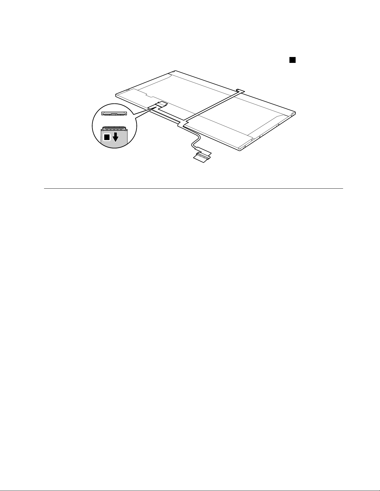
Note:TheLCDcablesareattachedtotheLCDpanelbyametalconnector.
6
Peelofftheadhesivetapeanddetachtheconnectorinthedirectionshownbythearrow
6.
Wheninstalling:Makesurethatthemetalconnectorisattachedrmly.
1170Integratedcamera
Foraccess,removetheseFRUsinorder:
•“1010Batterypack”onpage46
•“1020Dummycard”onpage47
•“1030Harddiskdrive(HDD)/memorymodule/miniPCIExpressCardslotcompartmentcover”onpage47
•“1040Harddiskdrive”onpage48
•“1050Opticaldrive”onpage49
•“1060Memorymodule”onpage50
•“1070PCIExpressMiniCardforwirelessLAN/WAN”onpage51
•“1080Keyboard”onpage53
•“1090Keyboardbezel”onpage54
•“1100Systemboardassembly”onpage56
•“1110LCDunit”onpage58
•“1150LCDfrontbezel”onpage66
•“1160LCDpanel,LCDcable,andhinges”onpage67
Chapter7.RemovingandreplacingaFRU69
Page 76

Removalstepsofintegratedcamera
1
Note:TheintegratedcameraisstuckonthetopcenteroftheLCDcover.Removetheintegratedcamera
fromtheLCDcover1.
Wheninstalling:SticktheintegratedcameratothetopcenteroftheLCDcoverandajusttheplacementof
ittomakesuretheconnectorisattachedrmly.
1180AntennaassemblyandLCDcover
Foraccess,removetheseFRUsinorder:
•“1010Batterypack”onpage46
•“1020Dummycard”onpage47
•“1030Harddiskdrive(HDD)/memorymodule/miniPCIExpressCardslotcompartmentcover”onpage47
•“1040Harddiskdrive”onpage48
•“1050Opticaldrive”onpage49
•“1060Memorymodule”onpage50
•“1070PCIExpressMiniCardforwirelessLAN/WAN”onpage51
•“1080Keyboard”onpage53
•“1090Keyboardbezel”onpage54
•“1100Systemboardassembly”onpage56
•“1110LCDunit”onpage58
•“1150LCDfrontbezel”onpage66
•“1160LCDpanel,LCDcable,andhinges”onpage67
70HardwareMaintenanceManual
Page 77

RemovalstepsofantennaassemblyandLCDcover
Peelofftheadhesivetapessecuringtheantennaboards,releasethecablesfromthecableguide,andthen
removetheantennaassemblyinthedirectionshownbythearrows1.
Wheninstalling:Routetheantennacablesalongthecableguidesandsecuretheantennaboardswith
adhesivetapes.Asyouroutethecables,makesurethattheyarenotsubjectedtoanytension.Tension
couldcausethecablestobedamagedbythecableguides,orawiretobebroken.
Chapter7.RemovingandreplacingaFRU71
Page 78

72HardwareMaintenanceManual
Page 79

Chapter8.Locations
5
4
3
6
8
2
2
9
1
8
7
10
11
12
3
Frontview
1Integratedcamera(Selectmodelsonly)7GPU(GraphicsProcessingUnit)switch(Selectmodels
only)
2Wirelessmoduleantennas(Selectmodelsonly)8Systemstatusindicators
3Speaker
4Powerbutton10Memorycardslot
5OneKeyRescueSystembutton11Wirelessdeviceswitch(Selectmodelsonly)
6Built-inmicrophone
9Touchpad
12Fingerprintreader(V570andB570)(Selectmodels
only)
1
1
:Forthedescriptionoftheindicator,see“Statusindicators”onpage39
.
©CopyrightLenovo2012
73
Page 80

Right-sideview
1
2
3
4
3
5
8
10
9
11
12
1
2
3
4
6
7
5
1Headphonejack
2Microphonejack5RJ-45port
3USBconnectors
4Opticaldrive
Bottomandleft-sideview
1Kensingtonslot
2acpoweradapterjack
3Fanlouvers9Batterypack
4VGAport10Batterylatch(manual)
5HDMIport(Selectmodelsonly)11SIMcardslot(Selectmodelsonly)
6eSA T A/USBcomboport(Selectmodelsonly)12Harddiskdrive(HDD)/Memory/MiniPCIExpressCard
7USBconnector
8Batterylatch(springloaded)
slotcompartment
74HardwareMaintenanceManual
Page 81

Chapter9.Partslist
Thischaptercontainsfollowinglistsoftheserviceparts.
•“Overall”onpage76
•“LCDFRUs”onpage80
•“Keyboard”onpage81
•“Miscellaneousparts”onpage82
•“acpoweradapters”onpage83
•“Powercords”onpage83
ExternalCRUstatementtocustomers:
Someproblemswithyourproductcanberesolvedwithareplacementpartyoucaninstallyourself,called
a“CustomerReplaceableUnit”or“CRU. ”SomeCRUsaredesignatedasSelf-serviceCRUsandothers
aredesignatedasOptional-serviceCRUs.InstallationofSelf-serviceCRUsisyourresponsibility;youmay
requestthatLenovoinstallsanOptional-serviceCRUaccordingtothewarrantyserviceforyourproduct.
WhereyouareinstallingtheCRU,LenovowillshiptheCRUtoyou.CRUinformationandreplacement
instructionsareshippedwithyourproductandareavailablefromLenovoatanytimeuponrequest.Youmay
ndalistofCRUsinthepublicationsthatshipwithyourproductorathttp://www.lenovo.com/CRUs.You
mayberequiredtoreturnthedefectivepartthatisreplacedbytheCRU.Whenreturnisrequired:(1)return
instructions,aprepaidshippinglabel,andacontainerwillbeincludedwiththereplacementCRU;and(2)you
maybechargedforthereplacementCRUifLenovodoesnotreceivethedefectivepartwithinthirty(30)days
ofyourreceiptofthereplacementCRU.SeeyourLenovoLimitedWarrantydocumentationforfulldetails.
LenovocomputerscontainthefollowingtypesofCRUs:
•Self-serviceCRUs:TheseCRUsunplugorareheldbynomorethantwoscrews.Examplesofthese
typesofCRUsincludeanacpoweradapter,apowercord,abattery,andaharddiskdrive.Other
Self-serviceCRUsdependingonproductdesignmayincludeamemorymodule,awirelesscard,a
keyboard,andapalmrestwithngerprintreaderandtouchpad.
•Optional-serviceCRUs:TheseCRUsareisolatedpartswithinthecomputerthatareconcealedbyan
accesspanelthatistypicallysecuredbymorethantwoscrews.Oncetheaccesspanelisremoved,the
specicCRUisvisible.
Note:EachFRUisavailableforalltypesormodels,unlessspecictypesormodelsarespecied.
©CopyrightLenovo2012
75
Page 82

Overall
1
14
h
15
16
19
c
20
9
11
12
18
17
b
21
13
3
6
7
a
4
e
5
d
f
2
8
10
i
g
j
76HardwareMaintenanceManual
Page 83

Table4.Partslist—Overall
No.
FRU(Overall)
1
LCDunit(see“LCDFRUs”onpage80.)
2
Keyboard(see“Keyboard”onpage81.)
3
LA57TOPCASEGRA YW/TP&MIC(V570)
3
LA57TOPCASEDARKGRAYW/TP&MIC(V570)
3
LB57UPPERCASEASSYW/TP&MIC(B570)
3
LB57EUpperCaseTEX-BLKW/TP .MIC(B570e)
4
LA57POWERBOARD
5
LA57TPBUTTONGRAYW/CABLE
5
LA57TPBUTTONDARKGRAYW/CABLE(V570)
6
LA57FINGERPRINTBOARD(V570andB570)
6
LB57EFingerPrintDummyCard(B570e)
7
LA57MBUMAW/OCPUDRAMW/3G/HDMI/APS(V570)
7
LA57MBUMAFORDUALCOREW/3G/HDMI/APS(V570)
7
LA57MBSGN12-1GHY7/SA8W/3G/HDMI/APS(V570)
7
LA57MBSGN12-2GHY5/SA6W/3G/HDMI/APS(V570)
7
LA57MBUMAFORQCNEWW/3G/HDMI/APSB3(V570)
7
LA57MBUMAFORDCNEWW/3G/HDMI/APSB3(V570)
7
LA57MBSGGE-1GW/3G/HDMI/APS/BTB3(V570)
7
LA57MBSGGE-2GW/3G/HDMI/APS/BTB3(V570)
7
LA57MBSGGS-2GW/3G/HDMI/APS/BTB3(V570)
7
LA57MBSGGS-1GW/3G/HDMI/APS/BTB3(V570)
7
LB57MBUMAW/3G/HDMIWO/CPU/DRAM/APS(B570)
7
LB57MBUMANEWW/3G/HDMIWO/APSB3(B570)
7
LB57MBSG1GW/3G/HDMIWO/APSB3(B570)
7
LB57MBSG1G8LW/3G/HDMIWO/APSB3(B570)
7
LB57MBSG512MW/3G/HDMIWO/APSB3(B570)
7
LB57MBSG512M8LW/3G/HDMIWO/APSB3(B570)
7
LB57EMBUMAW/HDMIWO/3G/APS(B570e)
7
LB57EMBDISGS-1GW/HDMIWO/3G/APS(B570e)
8
LA57RJ45/USBBOARD
9
LA57IOBOARD
10
LA57SDDUMMYCARD
11
IntelI7-2820QM2.30G8M4cD2PGAprocessor
11
IntelI7-2720QM2.20G6M4cD2PGAprocessor
11
IntelI7-2630QM2.0G6M4cD2PGAprocessor
11
IntelI7-2620M2.7G4M2cJ1PGAprocessor
11
IntelI5-2540M2.6G3M2cJ1PGAprocessor
FRUno.
31048974N
31051122N
31048999N
31052087N
11013298N
31048975N
31051121N
31048991N
31052088N
11013294N
11013377N
11013295N
11013296N
11013532N
11013533N
11013534N
11013535N
11014106N
11014128N
11013297N
11013536N
11013537N
11013650N
11013538N
11013651N
11014073N
11014185N
31048988N
11013299N
31048994*
102001055N
102001071N
102001070N
102001069N
102001068N
CRU
ID
Chapter9.Partslist77
Page 84

Table4.Partslist—Overall(continued)
No.
FRU(Overall)
11
IntelI5-2520M2.5G3M2cJ1PGAprocessor
11
IntelI5-2410M2.3G3M2cJ1PGAprocessor
11
IntelI3-2310M2.1G3M2cJ1PGAprocessor
12
LA57THERMALASSYUMA(FOX+DEL TA)
12
LA57THERMALASSYDIS(FOX+DEL T A)
13
DDRIII13331GB,M471B2873FHS-CH9(RevF/1Gb/46nm)
13
DDRIII13331GB,RMT1910MD66E7F-1333(V69A/2Gb/50nm)
13
DDRIII13331GB,HMT112S6DFR8C-H9N0(RevVega/1Gb/44nm)
13
DDRIII13331GB,RMT3010EF48E7W-1333(Rev.F/1Gb/60nm)
13
DDRIII13331GB,SY321NG08HBF(Vega/1Gb/44nm)
13
DDRIII13332GB,M471B5773CHS-CH9(RevC/2Gb/46nm)
13
DDRIII13332GB,EBJ21UE8BFU0-DJ-F(Rev.F/1Gb/60nm)
13
DDRIII13332GB,RMT1950MD58E8F-1333(V69A/2Gb/50nm)
13
DDRIII13332GB,HMT325S6BFR8C-H9N0(RevVega/2Gb/44nm)
13
DDRIII13332GB,RMT3020EF48E8W-1333(RevF/1Gb/60nm)
13
DDRIII13332GB,SY321NH08HAF(Vega/2Gb/44nm)
13
DDRIII13334GB,M471B5273CH0-CH9(RevC/2Gb/46nm)
13
DDRIII13334GB,HMT351S6BFR8C-H9N0(Vega/2Gb/44nm)
13
DDRIII13334GB,MT16JSF51264HZ-1G4D1(RevV69A/2Gb/50nm)
14
WLANcard,802.11a/g/n&&802.16e,Intel6250NXMOWMPCIENBHMC
14
WLANcard,802.11a/g/n&&802.16e,Intel6250GXMOWMPCIENBHMC
14
WLANcard,802.11a/g/n&&802.16e,Intel6150NXMOWMPCIENBHMC
14
WLANcard,802.11a/g/n&&802.16e,Intel6150GXMOWMPCIENBHMC
14
WLANcard,802.11b/g/n1×2,Intel1000NMOWMPCIENBHMC
14
WLANcard,802.11b/g/n2×2,CbtBCM43227MOWMPCIENBHMC
14
WLANcard,802.11b/g/n2×2,LiteonHB97MOWMPCIENBHMC
14
WLANcard,802.11b/g/n1×1,CbtBCM4313MOWMPCIENBHMC
14
WLANcard,802.11b/g/n1×1,LiteonAR9285HB95BGNMOWNB
14
WWANcard,WCDMA/HSDP A7.2M,EricssonF3307R2HSPA900/2100MHzWWAN
14
WWANcard,WCDMA/HSDP A7.2M,EricssonF3307R2HSPA850/1900MHzWWAN
14
WWANcard,WCDMA/HSDP A7.2M,HuaweiEM770WWCDMA+GPSMiniPCIEWWAN
14
WWANcard,WCDMA/HSDP A7.2M,HuaweiEM820HSPA+850/900/1900/2100MHz
14
WWANcard,EVDO,HuaweiEM660EVDO+GPSWWANcard
14
WWANcard,TD-SCDMA,LeadcoretechTD-SCDMALC5740Mini-Card
15
Bluetoothcard,BT2.1+EDR,FcnBCM92070BT2.1EDRFlashUNB
15
Bluetoothcard,BT2.1+EDR,USIBCM92070BT2.1EDRFlashUNB
16
Batterypack,6cell2.2Ah,SanyoL09S6Y023S2P48Whbty(LH)Comm01
FRUno.
102001067N
102001066N
102001065N
31048982N
31048983N
11011936**
11012427**
11012767**
11012634**
11012810**
11012630**
11012608**
11012213**
11012197**
11012633**
11012809**
11011934**
11012199**
11012320**
20002321**
20002388**
20002484**
20002529**
20002329**
20002506**
20002525**
20002505**
20002357**
11012853**
11012852**
11011800**
11012850**
11012299**
11012849**
20002266N
20002326N
121001091*
CRU
ID
78HardwareMaintenanceManual
Page 85

Table4.Partslist—Overall(continued)
No.
FRU(Overall)
16
Batterypack,6cell2.2Ah,PanaL10P6Y223S2P48WhbtyComm01
16
Batterypack,6cell2.2Ah,SMP/LGL09M6Y023S2P48Whbty(LH)Comm01
16
Batterypack,6cell2.2Ah,Celx/SL10C6Y023S2P48Whbty(LH)Comm01
16
Batterypack,6cell2.8Ah,PanaL10P6F213S2P62WhbtyComm01
16
Batterypack,6cell2.8Ah,SMP/SL10M6F213S2P62Whbty(LH)Comm01
17
LA57LOWERCASEUMAW/SPEAKER&DC-IN(V570/B570)
17
LA57LOWERCASEDISW/SPEAKER&DC-IN(V570/B570)
17
LB57LOWERCASEUMAW/SPK/DC-IN/SIM(V570/B570)
17
LB57LOWERCASEDISW/SPK/DC-IN/SIM(V570/B570)
17
LA57LOWERCASEUMANEWW/SPEAKER/DC-IN(V570/B570)
17
LA57LOWERCASEDISNEWW/SPEAKER/DC-IN(V570/B570)
17
LB57LOWERCASEUMANEWW/SPK/DC-IN/SIM(V570/B570)
17
LB57LOWERCASEDISNEWW/SPK/DC-IN/SIM(V570/B570)
17
LA57LOWERCASEUMANEWW/SPEAKER/DC-IN(B570e)
18
Harddiskdrive,320G5400rpmSATA,WD4Ksector320GN5400RPM250G
18
Harddiskdrive,320G5400rpmSATA,HitachiHTS545032B9A300320G9NB
18
Harddiskdrive,320G5400rpmSA T A,HitachiHTS543232A7A3845400RPM320G
18
Harddiskdrive,320G5400rpmSA T A,SeagateST320LT0205400RPM7MM320G
18
Harddiskdrive,320G5400rpmSATA,T oshibaMK3265GSX5400RPM320G
18
Harddiskdrive,500G5400rpmSATA,SeagateST9500325AS500G9NB
18
Harddiskdrive,500G5400rpmSA TA,WD5000BPVT-24HXZT15400RPM500G
18
Harddiskdrive,500G5400rpmSATA,HitachiHTS545050B9A300500G9NB
18
Harddiskdrive,500G5400rpmSATA,T oshibaMK5065GSX5400RPM500G
18
Harddiskdrive,640G5400rpmSA TA,WD6400BPVT-24HXZT15400RPM640G
18
Harddiskdrive,640G5400rpmSATA,T oshibaMK6465GSX5400RPM640G
18
Harddiskdrive,750G5400rpmSA TA,WD7500BPVT-24HXZT15400RPM750G
18
Harddiskdrive,320G7200rpmSA T A,HitachiHTS725032A9A3647200RPM320G
18
Harddiskdrive,320G7200rpmSA T A,SeagateST9320423AS7200RPM320G9NB
18
Harddiskdrive,320G7200rpmSATA,WDWD3200BEKT7200RPM320G
18
Harddiskdrive,320G7200rpmSA T A,HitachiHTS723232A7A3647200RPM320G
18
Harddiskdrive,320G7200rpmSA T A,SeagateST320LT0077200RPM7MM320G
18
Harddiskdrive,500G7200rpmSA T A,HitachiHTS725050A9A3647200RPM500G
18
Harddiskdrive,500G7200rpmSA T A,SeagateST9500420AS7200RPM500G9NB
18
Harddiskdrive,500G7200rpmSA TA,WD5000BEKT-24KA9T07200RPM500G
19
Opticaldrive,12.7mmT rayRambo,PLDSDS-8A5STrayinRambo
19
Opticaldrive,12.7mmT rayRambo,OptiarcAD-7710HT rayinRambo
19
Opticaldrive,12.7mmT rayRambo,TSSTTS-L633FT rayinRambo
FRUno.
121001096*
121001094*
121001071*
121001097*
121001095*
31048976N
31048977N
31049535N
31049536N
31049963N
31049958N
31049964N
31049965N
31049963N
16004853*
16004059*
16005024*
16005211*
16004642*
16004189*
16004846*
16004058*
16004643*
16004847*
16004644*
16004848*
16004530*
16004533*
16005212*
16005027*
16005030*
16004531*
16004532*
16004850*
25011187**
25011218**
25011201**
CRU
ID
Chapter9.Partslist79
Page 86

Table4.Partslist—Overall(continued)
7
2
6
3
4
5
8
No.
FRU(Overall)
19
Opticaldrive,12.7mmT rayRambo,PSNUJ8A0TrayinRambo
19
Opticaldrive,12.7mmBDCombo,PLDSDS-6E2STrayinBDCombo
19
Opticaldrive,12.7mmBDCombo,HLDSCT30NTrayinBDCombo
20
LA57ODDBEZELASSYT rayinRAMBO
20
LA57ODDBEZELASSYBLUERA YCOMBO
21
LA57HDDDOORASSY
LCDFRUs
InLenovoV570,B570,andB570emodels,thetypeofLCDis15.6-in.HDTFT.
FRUno.
25011472**
25011471**
25011473**
31048981**
31050482**
31048978N
CRU
ID
80HardwareMaintenanceManual
Page 87

Table5.Partslist—15.6-in.HDTFT
No.FRUFRUno.
1
LA57LCDBEZELW/CAMERAHOLE(V570)
1
LB57LCDBEZELW/CAMERAHOLE(B570)
1
LB57ELCDBezelBlackW/CameraHole(B570e)
2
LA57LCDSCREWHINGMYLAR
315.6HDLEDPanel,B156XW02V218004799N
3
15.6HDLEDPanel,N156BGE-L21
315.6HDLEDPanel,LP156WH4-TLA118004797N
315.6HDLEDPanel,LTN156AT16-L0118004796N
315.6HDLEDPanel,M156NWR2R018004795N
4
LA57LCDBRACKETW/HINGELEFT
4
LA57LCDBRACKETW/HINGERIGHT
5
LA47Camera2M56.18007.611/2/11.512/4(V570)
5
LB47CAMEARVGACHICONY/LITEON/BISON(B570/B570e)
6
LA57LCDCABLEW/CAMERACABLE
7
LA57LCDCOVERGRA YW/WLANANTENNA(V570)
7
LA57LCDCOVERDARKGRA YW/WLANANTENNA(V570)
7
LB57LCDCOVERW/WLANANTENNA(B570)
7
LB57ELCDCoverTEX-BLKW/Antenna(B570e)
31048965N
31048998N
31052086N
31048973N
18004798N
31048967N
31048971N
31047643N
31049002N
31048972N
31048966N
31051120N
31048997N
31052085N
CRU
ID
8
LA57LEDBOARDW/CABLE(V570)
8
LB57LEDBOARDW/CABLE(B570/B570e)
Keyboard
Table6.Partslist-Keyboard
LanguageFRUno.
(Dafan)
Arabic250126392501236125012462
Belgian250126562501236925012470
BrazilianPortuguese250126412501236225012463
Bulgarian250126822501237525012732
Czech
C&Nordics(Danish/Finnish/Swedish/Norwegian/English)
Dutch250126462501236425012465
French250126372501272925012460
French,English250126332501237725012456
German
250126812501237425012731
250126552501236825012469
250126382501236025012461
31048985N
31048995N
FRUno.
(Chicony)
FRUno.
(Sunrex)
Chapter9.Partslist81
Page 88

Table6.Partslist-Keyboard(continued)
LanguageFRUno.
(Dafan)
Greek
Hebrew250126502501236625012467
Hungarian250126522501236725012468
Icelandic250126592501237025012471
Italian250126272501272125012448
Japanese250126442501236325012464
Korean250126342501237625012457
Latin250126322501272625012455
Portuguese250126312501272525012454
Russian250126362501272825012459
Swiss
Slovenian
Spanish
Thai250126302501272425012453
TraditionalChinese
Turkish250126292501272325012452
U.K.English250126262501272025012451
U.S.English
U.S.English(International,withaEurosymbol)
250126472501236525012466
250126642501237225012473
250126612501237125012472
250126282501272225012450
250126352501272725012458
250126252501271925012449
250126662501237325012474
FRUno.
(Chicony)
FRUno.
(Sunrex)
Miscellaneousparts
Table7.Partslist-Miscellaneousparts
FRUFRUno.
(a)LA57FPBRACKET(V570andB570)
(b)LA57HDDBRACKETASSY
(c)LA57ODDBRACKET
(d)LB57TOUCHPADBRACKET(B570andB570e)
(e)LA57POWERBOARDCABLE
(f)LA57TOUCHPADCABLE
(g)LA57IOBOARDCABLE
(h)LA57BTCABLE
(i)LA57RJ45/USBBOARDCABLE
(j)LA57FINGERPRINTBOARDCABLE(V570andB570)
Note:Italicizedlettersinparenthesesarereferencestotheexplodedviewin“Overall”onpage76
31048993
31048979
31048980
31048996
31048984
31048986
31048990
31048987
31048989
31048992
82HardwareMaintenanceManual
Page 89

acpoweradapters
Table8.Partslist—3-pinacpoweradapters
FRUFRUno.
65W,DeltaADP-65KHBD,20V ,3.25Aadapter36001929N
65W,LiteonP A-1650-56LCadapter
65W,ChiconyCPA-A065,20V ,3.25Aadapter(330PF)
65W,EmersonAA26600L,20V ,3.25Aadapter36001870N
90W,DeltaADP-90DDBD,20V ,4.5Aadapter36001941N
90W,LiteonPA-1900-56LC,20V,4.5Aadapter(330PF)
90W,ChiconyCPA-A090,20V ,4.5Aadapter(330PF)
36001651N
36001943N
36001927N
36001942N
Powercords
ALenovopowercordforaspeciccountryorregionisusuallyavailableonlyinthatcountryorregion:
Table9.Partslist—3-pinpowercords(Linetek)
Countryorregion
Africa
•LS15+H03VV-F+PE-364,1m
Argentina
•LS15+H03VV-F+LP39,1m
Australia
•LS15+H03VV-F+LP-23A,1m
Brazil
•LS15H03VV-FLP26A,1m
CCC
•PC323+RVV300/300+LS15,1m
CE
•LP-34+H03VV-F+LS15,1m
Danmark
•LS15+H03VV-F+LP-38,1m
Indian
•PE-361+H05VV-F+LS15,1m
Israel
•LS15+H03VV-F+LP-41,1m
Italy
•LS15+H03VV-F+PE-336,1m
Japan
•LS15+VCTF+LP-54,1m
FRUno.
145000586*
145000599*
145000589*
145000596*
145000600*
145000585*
145000598*
145000592*
145000595*
145000591*
145000587*
CRU
ID
CRU
ID
Chapter9.Partslist83
Page 90

Table9.Partslist—3-pinpowercords(Linetek)(continued)
Countryorregion
Korea
•LS15+H05VV-F+LP-E04A,1m
Switzerland
•LS15+H03VV-F+LP-37,1m
Taiwan
•LS15+VCTF+LP-53,1m
U.K.
•LP-61L+H03VV-F+LS15,1m
UL
•LP-30B+SPT-2+LS15,1m
Table10.Partslist—3-pinpowercords(Longwell)
FRUno.
145000590*
145000597*
145000588*
145000593*
145000594*
CRU
ID
Countryorregion
Africa
•LP-39+H03VV-F+LS-18,1m
Argentina
•LP-24+H03VV-F+LS-18,1m
Australia
•LP-23A+LFC-3R+LS-18,1m
Brazil
•LP-46+H03VV-F+LS-18,1m
CCC
•LSG-31+RVV300/300+LS-18,1m
CE
•LongwellLP-34A+H03VV-F+LS-18,1m
Danmark
•LP-40+H03VV-F+LS-18,1m
Indian
•LP-67+BIS+LS-18,1m
Israel
•LP-41+H03VV-F+LS-18,1m
Italy
•LP-22+H03VV-F+LS-18,1m
Japan
•LP-54+VCTF+LS-18,1m
Korea
•LP-486+KTLH03VV-F+LS-5,1m
FRUno.
145000554*
145000567*
145000557*
145000564*
145000568*
145000553*
145000566*
145000560*
145000563*
145000559*
145000555*
145000558*
CRU
ID
84HardwareMaintenanceManual
Page 91

Table10.Partslist—3-pinpowercords(Longwell)(continued)
Countryorregion
Switzerland
•LP-37+H03VV-F+LS-18,1m
Taiwan
•LP-71+VCTF+LS-33,1m
U.K.
•LP-61L+H03VV-F+LS-18,1m
UL
•LP-30B+SPT-218AWG+LS-18,1m
Table11.Partslist—3-pinpowercords(Volex)
FRUno.
145000565*
145000556*
145000561*
145000562*
CRU
ID
Countryorregion
Argentina
•LP-24+H03VV-F+LS-18,1m
Australia
•LP-23A+LFC-3R+LS-18,1m
Brazil
•LP-46+H03VV-F+LS-18,1m
CCC
•LSG-31+RVV300/300+LS-18,1m
CE
•LP-34A+H03VV-F+LS-18,1m
Danmark
•LP-40+H03VV-F+LS-18,1m
Indian
•LP-67+BIS+LS-18,1m
Israel
•LP-41+H03VV-F+LS-18,1m
Italy
•LP-22+H03VV-F+LS-18,1m
Japan
•LP-54+VCTF+LS-18,1m
Korea
•LP-486+KTLH03VV-F+LS-5,1m
Switzerland
•LP-37+H03VV-F+LS-18,1m
Taiwan
•LP-71+VCTF+LS-33,1m
FRUno.
145000528*
145000532*
145000527*
145000538*
145000525*
145000534*
145000536*
145000526*
145000535*
145000530*
145000533*
145000524*
145000531*
CRU
ID
Chapter9.Partslist85
Page 92

Table11.Partslist—3-pinpowercords(Volex)(continued)
Countryorregion
U.K.
•LP-61L+H03VV-F+LS-18,1m
UL
•LP-30B+SPT-218AWG+LS-18,1m
Table12.Partslist—3-pinpowercords(others)
FRUno.
145000605*
145000537*
CRU
ID
Countryorregion
CCC
•SSDYD-118-1+IEC53RVV+SSD-3-2B-1,1m
FRUno.
145000602*
CRU
ID
86HardwareMaintenanceManual
Page 93

AppendixA.Notices
Lenovomaynotoffertheproducts,services,orfeaturesdiscussedinthisdocumentinallcountries.Consult
yourlocalLenovorepresentativeforinformationontheproductsandservicescurrentlyavailableinyour
area.AnyreferencetoaLenovoproduct,program,orserviceisnotintendedtostateorimplythatonlythat
Lenovoproduct,program,orservicemaybeused.Anyfunctionallyequivalentproduct,program,orservice
thatdoesnotinfringeanyLenovointellectualpropertyrightmaybeusedinstead.However,itistheuser's
responsibilitytoevaluateandverifytheoperationofanyotherproduct,program,orservice.
Lenovomayhavepatentsorpendingpatentapplicationscoveringsubjectmatterdescribedinthis
document.Thefurnishingofthisdocumentdoesnotgiveyouanylicensetothesepatents.Y oucansend
licenseinquiries,inwriting,to:
Lenovo(UnitedStates),Inc.
1009ThinkPlace-BuildingOne
Morrisville,NC27560
U.S.A.
Attention:LenovoDirectorofLicensing
LENOVOPROVIDESTHISPUBLICA TION“ ASIS”WITHOUTWARRANTYOFANYKIND,EITHEREXPRESS
ORIMPLIED,INCLUDING,BUTNOTLIMITEDTO,THEIMPLIEDWARRANTIESOFNON-INFRINGEMENT ,
MERCHANTABILITYORFITNESSFORAP ARTICULARPURPOSE.Somejurisdictionsdonotallow
disclaimerofexpressorimpliedwarrantiesincertaintransactions,therefore,thisstatementmaynotapply
toyou.
Thisinformationcouldincludetechnicalinaccuraciesortypographicalerrors.Changesareperiodically
madetotheinformationherein;thesechangeswillbeincorporatedinneweditionsofthepublication.
Lenovomaymakeimprovementsand/orchangesintheproduct(s)and/ortheprogram(s)describedinthis
publicationatanytimewithoutnotice.
Theproductsdescribedinthisdocumentarenotintendedforuseinimplantationorotherlifesupport
applicationswheremalfunctionmayresultininjuryordeathtopersons.Theinformationcontainedinthis
documentdoesnotaffectorchangeLenovoproductspecicationsorwarranties.Nothinginthisdocument
shalloperateasanexpressorimpliedlicenseorindemnityundertheintellectualpropertyrightsofLenovo
orthirdparties.Allinformationcontainedinthisdocumentwasobtainedinspecicenvironmentsandis
presentedasanillustration.Theresultobtainedinotheroperatingenvironmentsmayvary.
Lenovomayuseordistributeanyoftheinformationyousupplyinanywayitbelievesappropriatewithout
incurringanyobligationtoyou.
Anyreferencesinthispublicationtonon-LenovoWebsitesareprovidedforconvenienceonlyanddonotin
anymannerserveasanendorsementofthoseWebsites.ThematerialsatthoseWebsitesarenotpartof
thematerialsforthisLenovoproduct,anduseofthoseWebsitesisatyourownrisk.
Anyperformancedatacontainedhereinwasdeterminedinacontrolledenvironment.Therefore,theresult
obtainedinotheroperatingenvironmentsmayvarysignicantly.Somemeasurementsmayhavebeen
madeondevelopment-levelsystemsandthereisnoguaranteethatthesemeasurementswillbethesame
ongenerallyavailablesystems.Furthermore,somemeasurementsmayhavebeenestimatedthrough
extrapolation.Actualresultsmayvary.Usersofthisdocumentshouldverifytheapplicabledatafortheir
specicenvironment.
©CopyrightLenovo2012
87
Page 94

Trademarks
ThefollowingtermsaretrademarksofLenovointheUnitedStates,othercountriesorboth:
ActiveProtectionSystem
Lenovo
OneKeyRescue
WindowsisatrademarkoftheMicrosoftgroupofcompanies.
IntelisatrademarkofIntelCorporationoritssubsidiariesintheUnitedStates,othercountries,orboth.
Othercompany,product,orservicenamesmaybethetrademarksorservicemarksofothers.
88HardwareMaintenanceManual
Page 95

Page 96

PartNumber:
PrintedinChina
(1P)P/N:
**
 Loading...