

Page 1

IdeaCentreB540–B540P
ideaideaideaCentreidea
HardwareMaintenanceManual
Page 2

Page 3

IdeaCentreB540–B540P
HardwareMaintenanceManual
Page 4

ThirdEdition(July2013)25th
©CopyrightLenovo2013.
LIMITEDANDRESTRICTEDRIGHTSNOTICE:IfdataorsoftwarearedeliveredpursuantaGeneralServices
Administration“GSA”contract,use,reproduction,ordisclosureissubjecttorestrictionssetforthinContractNo.
GS-35F-05925
Page 5

Contents
Chapter1.Aboutthismanual......1
ImportantSafetyInformation..........1
Chapter2.Safetyinformation......3
Generalsafety................3
Electricalsafety...............3
Safetyinspectionguide............5
Handlingelectrostaticdischarge-sensitive
devices..................5
Groundingrequirements............6
Safetynotices................6
Chapter3.Generalinformation.....9
Specications................9
Chapter4.GeneralCheckout.....11
Chapter5.UsingtheSetupUtility...13
StartingtheLenovoBIOSSetupUtilityprogram.13
Viewingandchangingsettings........13
Usingpasswords..............13
Enablingordisablingadevice........15
Selectingastartupdevice..........16
ExitingtheLenovoBIOSSetupUtilityprogram..17
Chapter6.Symptom-to-FRUIndex..19
Harddiskdrivebooterror..........19
PowerSupplyProblems...........19
POSTerrorcodes.............20
Undeterminedproblems...........20
Chapter7.Locatingconnectors,
controlsandcomponents......21
Chapter8.Replacinghardware....27
Generalinformation.............27
Replacingthekeyboardandmouse......28
Replacingthepowercordorpoweradapter...28
Removingthecomputercover........29
Removingthecomputerstand........30
Replacingamemorymodule.........31
Replacingtheharddiskdrive.........32
Replacingtheopticaldrive..........33
Removingthemiddlecover.........35
Replacingtheconverterboard........37
RemovingtheEMIcover...........38
Replacingthecamera............39
ReplacingtheBluetoothmodule........40
Replacingthebattery............41
Replacingthesystemfan..........42
Removingthepowersupply.........43
Replacingtheheat-sink...........44
ReplacingtheCPU.............46
ReplacingtherearI/Omodule........48
ReplacingtheWi-Ficard...........49
ReplacingtheTVtunercard.........50
Replacingthespeakersystem........51
Replacingthetouchcontrolboard.......52
Replacingthescalarboard..........53
Replacingthemotherboard..........54
ReplacingtheLEDpanelmodule.......55
FRUlists.................57
Chapter9.Generalinformation....65
AdditionalServiceInformation........65
©CopyrightLenovo2013
iii
Page 6

ivIdeaCentreB540–B540PHardwareMaintenanceManual
Page 7
Chapter1.Aboutthismanual
ThismanualcontainsserviceandreferenceinformationforIdeaCentreB540&B540Pcomputerslistedon
thecover.ItisintendedonlyfortrainedservicerswhoarefamiliarwithLenovocomputerproducts.
BeforeservicingaLenovoproduct,besuretoreadtheSafetyInformation.
ThedescriptionoftheTVcardinthismanualisonlyusedforthemachineswhichhavetheTVcard.Itis
invalidforthosemachineswhichdonothaveTVcard.
ImportantSafetyInformation
Besuretoreadallcautionanddangerstatementsinthisbookbeforeperforminganyoftheinstructions.
VeuillezliretouteslesconsignesdetypeDANGERetA TTENTIONduprésentdocumentavantd’exécuter
lesinstructions.
LesenSieunbedingtalleHinweisevomT yp“ACHTUNG”oder“VORSICHT”indieserDokumentation,bevor
SieirgendwelcheVorgängedurchführen
LeggereleistruzioniintrodottedaATTENZIONEePERICOLOpresentinelmanualeprimadieseguireuna
qualsiasidelleistruzioni
Certique-sedelertodasasinstruçõesdecuidadoeperigonestemanualantesdeexecutarqualquer
umadasinstruções
Esimportantequeleatodaslasdeclaracionesdeprecauciónydepeligrodeestemanualantesdeseguir
lasinstrucciones.
©CopyrightLenovo2013
1
Page 8

2IdeaCentreB540–B540PHardwareMaintenanceManual
Page 9

Chapter2.Safetyinformation
Thischaptercontainsthesafetyinformationthatyouneedtobefamiliarwithbeforeservicingacomputer.
Generalsafety
Followtheserulestoensuregeneralsafety:
•Observegoodhousekeepingintheareaofthemachinesduringandaftermaintenance.
•Whenliftinganyheavyobject:
1.Ensureyoucanstandsafelywithoutslipping.
2.Distributetheweightoftheobjectequallybetweenyourfeet.
3.Useaslowliftingforce.Nevermovesuddenlyortwistwhenyouattempttolift.
4.Liftbystandingorbypushingupwithyourlegmuscles;thisactionremovesthestrainfromthe
musclesinyourback.
Donotattempttoliftanyobjectsthatweighmorethan16kg(35lb)orobjectsthatyouthinkare
tooheavyforyou.
•Donotperformanyactionthatcauseshazardstothecustomer,orthatmakestheequipmentunsafe.
•Beforeyoustartthemachine,ensurethatotherservicerepresentativesandthecustomer’spersonnelare
notinahazardousposition.
•Placeremovedcoversandotherpartsinasafeplace,awayfromallpersonnel,whileyouareservicing
themachine.
•Keepyourtoolcaseawayfromwalkareassothatotherpeoplewillnottripoverit.
•Donotwearlooseclothingthatcanbetrappedinthemovingpartsofamachine.Ensurethatyoursleeves
arefastenedorrolledupaboveyourelbows.Ifyourhairislong,fastenit.
•Inserttheendsofyournecktieorscarfinsideclothingorfastenitwithanonconductiveclip,approximately
8centimeters(3inches)fromtheend.
•Donotwearjewelry,chains,metal-frameeyeglasses,ormetalfastenersforyourclothing.
Remember:Metalobjectsaregoodelectricalconductors.
•Wearsafetyglasseswhenyouare:hammering,drillingsoldering,cuttingwire,attachingsprings,using
solvents,orworkinginanyotherconditionsthatmightbehazardoustoyoureyes.
•Afterservice,reinstallallsafetyshields,guards,labels,andgroundwires.Replaceanysafetydevice
thatiswornordefective.
•Reinstallallcoverscorrectlybeforereturningthemachinetothecustomer.
Electricalsafety
CAUTION:
Electricalcurrentfrompower,telephone,andcommunicationcablescanbehazardous.T oavoid
personalinjuryorequipmentdamage,disconnecttheattachedpowercords,telecommunication
systems,networks,andmodemsbeforeyouopenthecomputercovers,unlessinstructedotherwise
intheinstallationandcongurationprocedures.
©CopyrightLenovo2013
3
Page 10

Observethefollowingruleswhenworkingonelectricalequipment.
Important:Useonlyapprovedtoolsandtestequipment.Somehandtoolshavehandlescoveredwithasoft
materialthatdoesnotinsulateyouwhenworkingwithliveelectricalcurrents.Manycustomershave,near
theirequipment,rubberoormatsthatcontainsmallconductiveberstodecreaseelectrostaticdischarges.
Donotusethistypeofmattoprotectyourselffromelectricalshock.
•Findtheroomemergencypower-off(EPO)switch,disconnectingswitch,orelectricaloutlet.Ifanelectrical
accidentoccurs,youcanthenoperatetheswitchorunplugthepowercordquickly.
•Donotworkaloneunderhazardousconditionsornearequipmentthathashazardousvoltages.
•Disconnectallpowerbefore:
–Performingamechanicalinspection
–Workingnearpowersupplies
–RemovingorinstallingFieldReplaceableUnits(FRUs)
•Beforeyoustarttoworkonthemachine,unplugthepowercord.Ifyoucannotunplugit,askthecustomer
topower-offthewallboxthatsuppliespowertothemachineandtolockthewallboxintheoffposition.
•Ifyouneedtoworkonamachinethathasexposedelectricalcircuits,observethefollowingprecautions:
–Ensurethatanotherperson,familiarwiththepower-offcontrols,isnearyou.
Remember:Anotherpersonmustbetheretoswitchoffthepower,ifnecessary.
–Useonlyonehandwhenworkingwithpowered-onelectricalequipment;keeptheotherhandinyour
pocketorbehindyourback.
Remember:Theremustbeacompletecircuittocauseelectricalshock.Byobservingtheaboverule,
youmaypreventacurrentfrompassingthroughyourbody.
–Whenusingatester,setthecontrolscorrectlyandusetheapprovedprobeleadsandaccessoriesfor
thattester.
–Standonsuitablerubbermats(obtainedlocally,ifnecessary)toinsulateyoufromgroundssuchas
metaloorstripsandmachineframes.
Observethespecialsafetyprecautionswhenyouworkwithveryhighvoltages;theseinstructionsarein
thesafetysectionsofmaintenanceinformation.Useextremecarewhenmeasuringhighvoltages.
•Regularlyinspectandmaintainyourelectricalhandtoolsforsafeoperationalcondition.
•Donotusewornorbrokentoolsandtesters.
•Neverassumethatpowerhasbeendisconnectedfromacircuit.First,checkthatithasbeenpowered-off.
•Alwayslookcarefullyforpossiblehazardsinyourworkarea.Examplesofthesehazardsaremoistoors,
nongroundedpowerextensioncables,powersurges,andmissingsafetygrounds.
•Donottouchliveelectricalcircuitswiththereectivesurfaceofaplasticdentalmirror.Thesurfaceis
conductive;suchtouchingcancausepersonalinjuryandmachinedamage.
•Donotservicethefollowingpartswiththepoweronwhentheyareremovedfromtheirnormaloperating
placesinamachine:
–Powersupplyunits
–Pumps
–Blowersandfans
–Motorgenerators
andsimilarunits.(Thispracticeensurescorrectgroundingoftheunits.)
•Ifanelectricalaccidentoccurs:
–Usecaution;donotbecomeavictimyourself.
–Switchoffpower.
4IdeaCentreB540–B540PHardwareMaintenanceManual
Page 11

–Sendanotherpersontogetmedicalaid.
Safetyinspectionguide
Theintentofthisinspectionguideistoassistyouinidentifyingpotentiallyunsafeconditionsonthese
products.Eachmachine,asitwasdesignedandbuilt,hadrequiredsafetyitemsinstalledtoprotectusers
andservicepersonnelfrominjury.Thisguideaddressesonlythoseitems.However,goodjudgmentshould
beusedtoidentifypotentialsafetyhazardsduetoattachmentoffeaturesoroptionsnotcoveredbythis
inspectionguide.
Ifanyunsafeconditionsarepresent,youmustdeterminehowserioustheapparenthazardcouldbeand
whetheryoucancontinuewithoutrstcorrectingtheproblem.
Considertheseconditionsandthesafetyhazardstheypresent:
•Electricalhazards,especiallyprimarypower(primaryvoltageontheframecancauseseriousorfatal
electricalshock).
•Explosivehazards,suchasadamagedCRTfaceorbulgingcapacitor
•Mechanicalhazards,suchaslooseormissinghardware
Theguideconsistsofaseriesofstepspresentedinachecklist.Beginthecheckswiththepoweroff,and
thepowercorddisconnected.
Checklist:
1.Checkexteriorcoversfordamage(loose,broken,orsharpedges).
2.Power-offthecomputer.Disconnectthepowercord.
3.Checkthepowercordfor:
a.Athird-wiregroundconnectoringoodcondition.Useametertomeasurethird-wireground
continuityfor0.1ohmorlessbetweentheexternalgroundpinandframeground.
b.Thepowercordshouldbetheappropriatetypeasspeciedinthepartslistings.
c.Insulationmustnotbefrayedorworn.
4.Removethecover.
5.Checkforanyobviousalterations.Usegoodjudgmentastothesafetyofanyalterations.
6.Checkinsidetheunitforanyobviousunsafeconditions,suchasmetallings,contamination,wateror
otherliquids,orsignsofreorsmokedamage.
7.Checkforworn,frayed,orpinchedcables.
8.Checkthatthepower-supplycoverfasteners(screwsorrivets)havenotbeenremovedortamperedwith.
Handlingelectrostaticdischarge-sensitivedevices
Anycomputerpartcontainingtransistorsorintegratedcircuits(ICs)shouldbeconsideredsensitiveto
electrostaticdischarge(ESD).ESDdamagecanoccurwhenthereisadifferenceinchargebetweenobjects.
ProtectagainstESDdamagebyequalizingthechargesothatthemachine,thepart,theworkmat,andthe
personhandlingthepartareallatthesamecharge.
Notes:
1.Useproduct-specicESDprocedureswhentheyexceedtherequirementsnotedhere.
2.MakesurethattheESDprotectivedevicesyouusehavebeencertied(ISO9000)asfullyeffective.
WhenhandlingESD-sensitiveparts:
•Keepthepartsinprotectivepackagesuntiltheyareinsertedintotheproduct.
Chapter2.Safetyinformation5
Page 12

•Avoidcontactwithotherpeoplewhilehandlingthepart.
•Wearagroundedwriststrapagainstyourskintoeliminatestaticonyourbody.
•Preventthepartfromtouchingyourclothing.Mostclothingisinsulativeandretainsachargeevenwhen
youarewearingawriststrap.
•Usetheblacksideofagroundedworkmattoprovideastatic-freeworksurface.Thematisespecially
usefulwhenhandlingESD-sensitivedevices.
•Selectagroundingsystem,suchasthoselistedbelow,toprovideprotectionthatmeetsthespecic
servicerequirement.
Note:TheuseofagroundingsystemisdesirablebutnotrequiredtoprotectagainstESDdamage.
–AttachtheESDgroundcliptoanyframeground,groundbraid,orgreen-wireground.
–UseanESDcommongroundorreferencepointwhenworkingonadouble-insulatedor
battery-operatedsystem.Youcanusecoaxorconnector-outsideshellsonthesesystems.
–Usetheroundground-prongoftheacplugonac-operatedcomputers.
Groundingrequirements
Electricalgroundingofthecomputerisrequiredforoperatorsafetyandcorrectsystemfunction.Proper
groundingoftheelectricaloutletcanbeveriedbyacertiedelectrician.
Safetynotices
ThecautionanddangersafetynoticesinthissectionareprovidedinthethelanguageofEnglish.
DANGER
Electricalcurrentfrompower,telephoneandcommunicationcablesishazardous.
Toavoidashockhazard:
•Donotconnectordisconnectanycablesorperforminstallation,maintenance,orreconguration
ofthisproductduringanelectricalstorm.
•Connectallpowercordstoaproperlywiredandgroundedelectricaloutlet.
•Connecttoproperlywiredoutletsanyequipmentthatwillbeattachedtothisproduct.
•Whenpossible,useonehandonlytoconnectordisconnectsignalcables.
•Neverturnonanyequipmentwhenthereisevidenceofre,water ,orstructuraldamage.
•Disconnecttheattachedpowercords,telecommunicationssystems,networks,andmodems
beforeyouopenthedevicecovers,unlessinstructedotherwiseintheinstallationandconguration
procedures.
•Connectanddisconnectcablesasdescribedinthefollowingtablewheninstalling,moving,or
openingcoversonthisproductorattacheddevices.
6IdeaCentreB540–B540PHardwareMaintenanceManual
Page 13
ToConnect
1.TurneverythingOFF .
2.First,attachallcablestodevices.
3.Attachsignalcablestoconnectors.
4.Attachpowercordstooutlet.
5.TurndeviceON.
ToDisconnect
1.TurneverythingOFF .
2.First,removepowercordsfromoutlet.
3.Removesignalcablesfromconnectors.
4.Removeallcablesfromdevices.
CAUTION:
Whenreplacingthelithiumbattery,useonlyPartNumber45C1566oranequivalenttypebattery
recommendedbythemanufacturer.Ifyoursystemhasamodulecontainingalithiumbattery,replace
itonlywiththesamemoduletypemadebythesamemanufacturer.Thebatterycontainslithiumand
canexplodeifnotproperlyused,handled,ordisposedof.
Donot:
•Throworimmerseintowater
•Heattomorethan100°C(212°F)
•Repairordisassemble
Disposeofthebatteryasrequiredbylocalordinancesorregulations.
CAUTION:
Whenlaserproducts(suchasCD-ROMs,DVD-ROMdrives,beropticdevices,ortransmitters)are
installed,notethefollowing:
•Donotremovethecovers.Removingthecoversofthelaserproductcouldresultinexposureto
hazardouslaserradiation.Therearenoserviceablepartsinsidethedevice.
•Useofcontrolsoradjustmentsorperformanceofproceduresotherthanthosespeciedherein
mightresultinhazardousradiationexposure.
DANGER
SomelaserproductscontainanembeddedClass3AorClass3Blaserdiode.Notethefollowing:
Laserradiationwhenopen.Donotstareintothebeam,donotviewdirectlywithoptical
instruments,andavoiddirectexposuretothebeam.
Chapter2.Safetyinformation7
Page 14

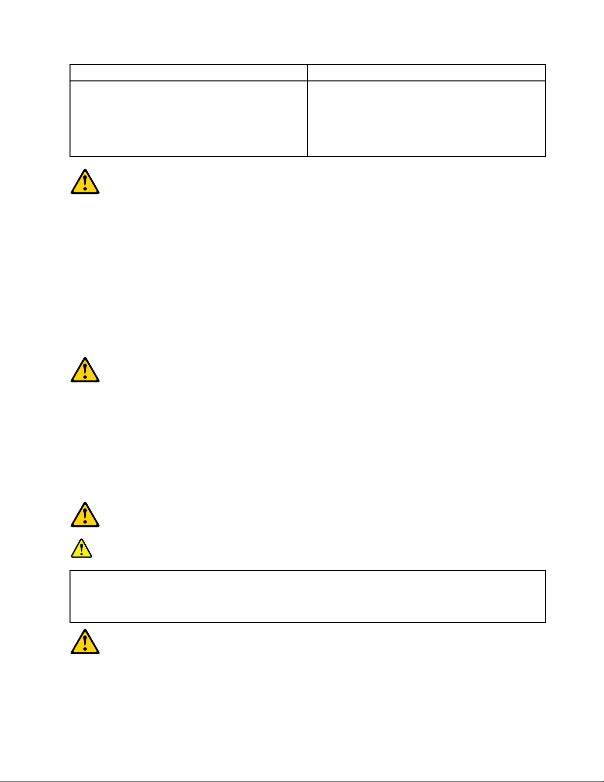
≥18kg(37lbs)≥32kg(70.5lbs)≥55kg(121.2lbs)
1
2
CAUTION:
Usesafepracticeswhenlifting.
CAUTION:
Thepowercontrolbuttononthedeviceandthepowerswitchonthepowersupplydonotturnoff
theelectricalcurrentsuppliedtothedevice.Thedevicealsomighthavemorethanonepower
cord.Toremoveallelectricalcurrentfromthedevice,ensurethatallpowercordsaredisconnected
fromthepowersource.
CAUTION:
Donotplaceanyobjectweighingmorethan82kg(180lbs.)ontopofrack-mounteddevices.
8IdeaCentreB540–B540PHardwareMaintenanceManual
Page 15

Chapter3.Generalinformation
Thischapterprovidesgeneralinformationthatappliestoallmachinetypessupportedbythispublication.
Specications
Thissectionliststhephysicalspecicationsforyourcomputer.
Thissectionliststhephysicalspecicationsforyourcomputer.
TypeIdeaCentreB540&B540P
Thissectionliststhephysicalspecications.
Environment
Airtemperature:
Operating:10°to35°C
Transit:-20°to55°C
Humidity:
Operating:35%to80%
Transit:20%to90%(40°C)
Altitude:86KPato106KPa
Electricalinput:
Inputvoltage:90V-264V(AC)
Inputfrequency:47Hz-63Hz
©CopyrightLenovo2013
9
Page 16

10IdeaCentreB540–B540PHardwareMaintenanceManual
Page 17

Chapter4.GeneralCheckout
Attention:Thedrivesinthecomputeryouareservicingmighthavebeenrearrangedorthedrivestartup
sequencechanged.Beextremelycarefulduringwriteoperationssuchascopying,saving,orformatting.
Dataorprogramscanbeoverwrittenifyouselectanincorrectdrive.
Generalerrormessagesappearifaproblemorconictisfoundbyanapplicationprogram,theoperating
system,orboth.Foranexplanationofthesemessages,refertotheinformationsuppliedwiththatsoftware
package.
Usethefollowingproceduretohelpdeterminethecauseoftheproblem:
1.Power-offthecomputerandallexternaldevices.
2.Checkallcablesandpowercords.
3.Setalldisplaycontrolstothemiddleposition.
4.Power-onallexternaldevices.
5.Power-onthecomputer.
•Lookfordisplayederrorcodes
•Lookforreadableinstructionsoramainmenuonthedisplay.
Ifyoudidnotreceivethecorrectresponse,proceedtostep6.
Ifyoudoreceivethecorrectresponse,proceedtostep7.
6.Lookatthefollowingconditionsandfollowtheinstructions:
•IfthecomputerdisplaysaPOSTerror,goto“POSTerrorcodes” .
•Ifthecomputerhangsandnoerrorisdisplayed,continueatstep7.
7.Iftheteststopsandyoucannotcontinue,replacethelastdevicetested.
©CopyrightLenovo2013
11
Page 18

12IdeaCentreB540–B540PHardwareMaintenanceManual
Page 19

Chapter5.UsingtheSetupUtility
TheSetupUtilityprogramisusedtoviewandchangethecongurationsettingsofyourcomputer,regardless
ofwhichoperatingsystemyouareusing.However,theoperating-systemsettingsmightoverrideanysimilar
settingsintheSetupUtilityprogram.
StartingtheLenovoBIOSSetupUtilityprogram
TostarttheLenovoBIOSSetupUtilityprogram,dothefollowing:
1.Ifyourcomputerisalreadyonwhenyoustartthisprocedure,shutdowntheoperatingsystemand
turnoffthecomputer.
2.PressandholdtheF1keythenturnonthecomputer.WhentheLenovoBIOSSetupUtilityprogramis
displayed,releasetheF1key.
Note:IfaPower-OnPasswordoranAdministratorPasswordhasbeenset,theSetupUtilityprogrammenu
isnotdisplayeduntilyoutypeyourpassword.Formoreinformation,see“Usingpasswords.”
Viewingandchangingsettings
SystemcongurationoptionsarelistedintheLenovoBIOSSetupUtilityprogrammenu.Tovieworchange
settings,see“StartingtheSetupUtilityprogram.”
YoumustusethekeyboardwhenusingtheLenovoBIOSSetupUtilitymenu.Thekeysusedtoperform
varioustasksaredisplayedonthebottomofeachscreen.
Usingpasswords
YoucanusetheLenovoBIOSSetupUtilityprogramtosetpasswordstopreventunauthorizedpersons
fromgainingaccesstoyourcomputeranddata.See“StartingtheSetupUtilityprogram.”Thefollowing
typesofpasswordsareavailable:
•AdministratorPassword
•Power-OnPassword
Youdonothavetosetanypasswordstouseyourcomputer.However,ifyoudecidetosetpasswords,read
thefollowingsections.
Passwordconsiderations
Apasswordcanbeanycombinationoflettersandnumbersupto16character(a-z,and0-9).Forsecurity
reasons,itisagoodideatouseastrongpasswordthatcannotbeeasilycompromised.Wesuggestthat
passwordsshouldfollowtheserules:
•Strongpasswordscontain7-16characters,combinelettersandnumbers.
•Donotuseyournameoryourusername.
•Donotuseacommonwordoracommonname.
•Besignicantlydifferentfromyourpreviouspassword.
Attention:AdministratorandPower-Onpasswordsarenotcasesensitive
©CopyrightLenovo2013
13
Page 20

AdministratorPassword
SettinganAdministratorPassworddetersunauthorizedpersonsfromchangingcongurationsettings.Y ou
mightwanttosetanAdministratorPasswordifyouareresponsibleformaintainingthesettingsofseveral
computers.
AfteryousetanAdministratorPassword,apasswordpromptisdisplayedeverytimeyouaccesstheLenovo
BIOSSetupUtilityprogram.
IfboththeAdministratorandPower-OnPasswordareset,youcantypeeitherpassword.However,youmust
useyourAdministratorPasswordtochangeanycongurationsettings.
Setting,changing,ordeletinganAdministratorpassword
TosetanAdministratorPassword,dothefollowing:
Note:Apasswordcanbeanycombinationoflettersandnumbersupto16character(a-z,and0-9).For
moreinformation,see“Passwordconsiderations”onpage13.
1.StarttheLenovoBIOSSetupUtilityprogram(see“StartingtheLenovoBIOSSetupUtilityprogram”on
page13).
2.FromtheSecuritymenu,selectSetAdministratorPasswordandpresstheEnterkey.
3.Thepassworddialogboxwillbedisplayed.TypethepasswordthenpresstheEnterkey.
4.Re-typethepasswordtoconrm,thenpresstheEnterkey.Ifyoutypethepasswordcorrectly,the
passwordwillbeinstalled.
TochangeanAdministratorPassword,dothefollowing:
1.StarttheLenovoBIOSSetupUtilityprogram(see“StartingtheLenovoBIOSSetupUtilityprogram”on
page13).
2.FromtheSecuritymenu,selectSetAdministratorPasswordandpresstheEnterkey.
3.Thepassworddialogboxwillbedisplayed.TypethecurrentpasswordthenpressEnterkey.
4.T ypethenewpassword,thenpressEnterkey.Re-typethepasswordtoconrmthenewpassword,if
youtypethenewpasswordcorrectly,thenewpasswordwillbeinstalled.ASetupNoticewilldisplay
thatchangeshavebeensaved.
TodeleteapreviouslysetAdministratorPassword,dothefollowing:
1.FromtheSecuritymenu,selectSetAdministratorPasswordandpresstheEnterkey.
2.Thepassworddialogboxwillbedisplayed.TypethecurrentpasswordandpresstheEnterkey.
3.T odeleteanAdministratorPassword,Enterblankeldsforeachnewpasswordlineitem.Asetup
noticewilldisplaythatchangeshavebeensaved.
4.ReturntotheLenovoBIOSSetupUtilityprogrammenuandselecttheExitoption.
5.SelectSavechangesandExitfromthemenu.
Power-OnPassword
WhenaPower-OnPasswordisset,youcannotstarttheLenovoBIOSSetupUtilityprogramuntilavalid
passwordistypedfromthekeyboard.
Setting,changing,ordeletingaPower-OnPassword
Note:Apasswordcanbeanycombinationoflettersandnumbersupto16character(a-z,and0-9).
14IdeaCentreB540–B540PHardwareMaintenanceManual
Page 21

TosetaPower-OnPassword,dothefollowing:
1.StarttheLenovoBIOSSetupUtilityprogram(See”StartingtheLenovoBIOSSetupUtilityprogram”on
page13.)
2.FromtheSecuritymenu,selectSetPower-OnPasswordandpresstheEnterkey.
3.Thepassworddialogboxwillbedisplayed.Typethepassword,andpresstheEnterkey.
4.Re-typethepasswordtoconrm,ifyoutypethepasswordcorrectly,thepasswordwillbeinstalled.
TochangeaPower-OnPassword,dothefollowing:
1.StarttheLenovoBIOSSetupUtilityprogram(See”StartingtheLenovoBIOSSetupUtilityprogram”on
page13.)
2.FromtheSecuritymenu,selectSetPower-OnPasswordandpresstheEnterkey.
3.Thepassworddialogboxwillbedisplayed.TypethecurrentpasswordthenpresstheEnterkey.
4.T ypethenewpassword,thenpresstheEnterkey.Re-typethepasswordtoconrmthenewpassword,
ifyoutypethenewpasswordcorrectly,thenewpasswordwillbeinstalled.Asetupnoticewilldisplay
thatchangeshavebeensaved.
TodeleteapreviouslysetPower-OnPassword,dothefollowing:
1.FromtheSecuritymenu,selectSetPower-OnPasswordandpresstheEnterkey.
2.Thepassworddialogboxwillbedisplayed.TypethecurrentpasswordandpresstheEnterkey.
3.T odeletethePower-OnPassword,Enterblankeldsforeachnewpasswordlineitem.Asetup
noticewilldisplaythatchangeshavebeensaved.
4.ReturntotheLenovoBIOSSetupUtilityprogrammenuandselecttheExitoption.
5.SelectSavechangesandExitfromthemenu.
Enablingordisablingadevice
TheDevicesoptionsisusedtoenableordisableuseraccesstothefollowingdevices:
USBFunctionsSelectwhethertoenableordisableUSB(UniversalSerial
Bus)functions.Ifthefunctionsaredisabled,noUSB
devicescanbeused.
ATADriveSetupSelectIDEorACHImode.Devicedriversupportis
requiredforACHImode.Dependingonhowtheharddisk
imagewasinstalled,changingthissettingmayprevent
thesystemfrombooting.
OnboardAudioControllerSelectwhethertoenableordisabletheOnboardAudio
Controller,whenfeatureissettoDisabledalldevices
connectedtotheaudioconnectors(e.g.aheadphoneor
amicrophone)aredisabledandcan’tbeused.
OnboardEthernetControllerorBootAgentSelectwhethertoenableordisableOnboardEthernet
Controller,orselectwhethertoenableordisableload
onboardPXE(PrebootExecutionEnvironment),or
SMC(SecureManagedClient).Thisfeaturewillallow
thecomputertobootfromaserverimage.
Toenableordisableadevice,dothefollowing:
1.StarttheSetupUtilityprogram(see“StartingtheSetupUtilityprogram”onpage13).
2.FromtheSetupUtilityprogrammenu,selectDevices.
3.Select:
Chapter5.UsingtheSetupUtility15
Page 22

USBSetuppresstheEnterkey,andthenselectUSBFunctions.
ATADeviceSetuppresstheEnterkey.SelectCongureSAT Aas,presstheEnterkeyandthen
selectSATAmode.
AudioSetuppresstheEnterkey,andthenselectOnboardAudioController.
NetworkSetuppresstheEnterkey,thenselectOnboardEthernetSupportorBootAgent.
4.SelectDisabledorEnabledandpresstheEnterkey.
5.ReturntotheLenovoBIOSSetupUtilityprogrammenuandselecttheExitoption.
6.SelectSavechangesandExitfromthemenu.
Note:Ifyoudonotwanttosavethesettings,selectDiscardchangesandExitfromthemenu.
Selectingastartupdevice
IfyourcomputerdoesnotbootfromadevicesuchastheCD/DVD-ROMdrivediskorharddiskasexpected,
followoneoftheproceduresbelow.
Selectingatemporarystartupdevice
Usethisproceduretostartupfromanybootdevice.
Note:NotallCDs,DVDsorharddiskdrivesarebootable.
1.T urnoffyourcomputer.
2.PressandholdtheF12keythenturnonthecomputer.WhentheStartupDeviceMenuappears,
releasetheF12key.
Note:IftheStartupDeviceMenudoesnotdisplayusingthesesteps,repeatedlypressandreleasethe
F12keyratherthankeepingitpressedwhenturningonthecomputer.
3.Use↑and↓arrowstoselectthedesiredstartupdevicefromtheStartupDeviceMenuandpress
theEnterkeytobegin.
Note:SelectingastartupdevicefromtheStartupDeviceMenudoesnotpermanentlychangethe
startupsequence.
Selectingorchangingthestartupdevicesequence
Tovieworpermanentlychangetheconguredstartupdevicesequence,dothefollowing:
1.StarttheLenovoBIOSSetupUtilityprogram(see“StartingtheLenovoBIOSSetupUtilityprogram”on
page13).
2.FromtheLenovoBIOSSetupUtilityprogrammainmenu,selecttheStartupoption.
3.PresstheEnterkey,andselectthedevicesforthePrimaryBootSequence.Readtheinformation
displayedontherightsideofthescreen.
4.Use↑and↓arrowstoselectadevice.Usethe<+>or<->keystomoveadeviceupordown.Usethe
<×>keytoexcludethedevicefromorincludethedeviceinthebootsequence.
5.ReturntotheLenovoBIOSSetupUtilityprogrammenuandselecttheExitoption.
6.SelectSavechangesandExitfromthemenu.
Notes:
a.Ifyoudonotwanttosavethesettings,selectDiscardchangesandExitfromthemenu.
16IdeaCentreB540–B540PHardwareMaintenanceManual
Page 23

b.Ifyouhavechangedthesesettingsandwanttoreturntothedefaultsettings,selectLoadOptimal
Defaultsfromthemenu.
ExitingtheLenovoBIOSSetupUtilityprogram
Afteryounishviewingorchangingsettings,presstheEsckeytoreturntotheLenovoBIOSSetupUtility
programmainmenu.Y oumighthavetopresstheEsckeyseveraltimes.Dooneofthefollowing:
•Ifyouwanttosavethenewsettings,selectSavechangesandExitfromthemenu.WhentheSave&
resetwindowshows,selecttheY esbutton,andthenpresstheEnterkeytoexittheLenovoBIOS
SetupUtilityprogram.
•Ifyoudonotwanttosavethesettings,selectDiscardchangesandExitfromthemenu.Whenthe
ResetWithoutSavingwindowshows,selecttheYesbutton,andthenpresstheEnterkeytoexitthe
SetupUtilityprogram.
Chapter5.UsingtheSetupUtility17
Page 24

18IdeaCentreB540–B540PHardwareMaintenanceManual
Page 25

Chapter6.Symptom-to-FRUIndex
TheSymptom-to-FRUindexlistserrorsymptomsandpossiblecauses.Themostlikelycauseislistedrst.
AlwaysbeginwithChapter4,“GeneralCheckout,”onpage11.Thisindexcanalsobeusedtohelpyou
decidewhichFRUstohaveavailablewhenservicingacomputer.Ifyouareunabletocorrecttheproblem
usingthisindex,goto“Undeterminedproblems”onpage20.
Notes:
•Ifyouhavebothanerrormessageandanincorrectaudioresponse,diagnosetheerrormessagerst.
•Ifyoucannotrunthediagnostictestsoryougetadiagnosticerrorcodewhenrunningatestbutdid
receiveaPOSTerrormessage,diagnosethePOSTerrormessagerst.
•Ifyoudidnotreceiveanyerrormessagelookforadescriptionofyourerrorsymptomsintherstpartof
thisindex.
Harddiskdrivebooterror
Aharddiskdrivebooterrorcanhavethefollowingcauses.
Error
Thestartupdriveisnotincludedinthebootsequence
inconguration.
Nooperatingsysteminstalledonthebootdrive.Installanoperatingsystemonthebootdrive.
Thebootsectoronthestartupdriveiscorrupted.
Thedriveisdefective.
FRU/Action
Checkthecongurationandensurethestartupdriveis
inthebootsequence.
Thedrivemustbeformatted.Dothefollowing:
1.Attempttoback-upthedataonthefailingharddisk
drive.
2.Usetheoperatingsystemtoformattheharddisk
drive.
Replacetheharddiskdrive.
PowerSupplyProblems
Followtheseproceduresifyoususpectthereisapowersupplyproblem.
Check/VerifyFRU/Action
Checkthatthefollowingareproperlyinstalled:
•PowerCord
•On/OffSwitchconnector
•SystemBoardPowerSupplyconnectors
•Microprocessor(s)connection
Checkthepowercord.PowerCord
Checkthepower-onswitch.Power-onSwitch
Reseatconnectors
©CopyrightLenovo2013
19
Page 26

POSTerrorcodes
Eachtimeyouturnthecomputeron,itperformsaseriesofteststocheckthatthesystemisoperating
correctlyandthatcertainoptionsareset.ThisseriesoftestsiscalledthePower-OnSelf-T est,orPOST.
POSTdoesthefollowing:
•Checkssomebasicsystem-boardoperations
•Checksthatthememoryisworkingcorrectly
•Startsvideooperations
•Veriesthatthebootdriveisworking
POSTErrorMessageDescription/Action
Keyboarderror
RebootandSelectproperBootdeviceorInsertBoot
MediainselectedBootdevice
Cannotinitializethekeyboard.Makesurethekeyboard
isproperlyconnectedtothecomputerandthatnokeys
areheldpressedduringPOST .T opurposelycongure
thecomputerwithoutakeyboard,selectKeyboardless
operationinStartupoptiontoEnabled.TheBIOSthen
ignoresthemissingkeyboardduringPOST.
TheBIOSwasunabletondasuitablebootdevice.Make
surethebootdriveisproperlyconnectedtothecomputer.
Makesureyouhavebootablemediainthebootdevice.
Undeterminedproblems
1.Power-offthecomputer.
2.Removeordisconnectthefollowingcomponents(ifconnectedorinstalled)oneatatime.
a.Externaldevices(modem,printer,ormouse)
b.Extendedvideomemory
c.ExternalCache
d.ExternalCacheRAM
e.Harddiskdrive
f.Diskdrive
3.Power-onthecomputertore-testthesystem.
4.Repeatsteps1through3untilyoundthefailingdeviceorcomponent.
Ifalldevicesandcomponentshavebeenremovedandtheproblemcontinues,replacethesystemboard.
20IdeaCentreB540–B540PHardwareMaintenanceManual
Page 27

Chapter7.Locatingconnectors,controlsandcomponents
1
2
3 7 8 9
10 11 12 13 14
654
Thissectionprovidesillustrationstohelplocatethevariousconnectors,controlsandcomponentsofthe
computer.
Fontview
Thefollowingillustrationshowsthelocationofcontrolsandcomponentsonthefrontofthecomputer.
Attention:Becarefulnottoblockanyairventsonthecomputer.Blockedairventscancauseoverheating.
1.Built-inmicrophone8.Volumedown
2.Built-incamera9.Volumeup
3.Built-inIREmitter(donotblock,selectedmodelsonly)
4.Harddiskdriveindicator11.Brightnessup
5.Bluetoothstatusindicator12.Novovisionbutton
6.Wi-Fistatusindicator
7.TVindicator
10.Brightnessdown
13.PCmode/HDMI-in/AV-inswitch
14.MonitorOn/Off
Attention:TheeffectiverangeoftheBuilt-inIREmitteris10feet(3m).
©CopyrightLenovo2013
21
Page 28

Leftandrightview
1
2
3
4
5
6
7
8
Thefollowingillustrationshowsthelocationofconnectors,controlsandcomponentsontheleftandright
sideofthecomputer.
1.Opticaldrive
5.Microphoneport
2.TVbuttons(selectedmodelsonly)6.USBconnector
3.USBconnector
7.Memorycardreader
4.Headphoneport8.Powerbutton
22IdeaCentreB540–B540PHardwareMaintenanceManual
Page 29

Rearview
1
7
3 4
6
2 5
8
8
Thefollowingillustrationshowsthelocationofconnectorsandcomponentsontherearofthecomputer.
1.Ethernetport
5.AV-INconnectors(selectedmodelsonly)
2.USBconnectors6.TVtunerports(selectedmodelsonly)
3.HDMI-OUTconnector
7.Powerconnector
4.HDMI-INconnector(selectedmodelsonly)8.Airvents(donotblock)
Chapter7.Locatingconnectors,controlsandcomponents23
Page 30

Hardwarecomponents
1
2
1
5
6
7
8
9
3
4
10
11 12
13
14
15
16
17
19
18
20
21
22
23
24
25
26
Thefollowingillustrationshowsthecomponentsthatmakeupyourcomputer.
1.Rearcover
14.Opticaldiskdrive
2.Computerstand15.HardwareTVScaleBoard
3.Middlecover16.WLANcard
4.FrontLEDindicatorboard
5.EMIcover
6.Chassis
7.LEDpanel
8.Frontbezel
17.Speakers
18.Converter
19.Heat-sink
20.Infraredmodule
21.Systemfans
9.Glass22.Camera
10.RearI/Omodule
23.HardwareTVtunerboard
11.Powersupply24.HardwareTVswitchboard
12.Motherboard25.Touchmodule
13.Harddiskdrive26.Bluetoothmodule
24IdeaCentreB540–B540PHardwareMaintenanceManual
Page 31

Identifyingpartsonthemotherboard
1
2
3
6
7
8
9
10
10 1011 12 13 14 15
16
17
18
18
19
20
21
4
5
22232325 24
Themotherboard(sometimescalledtheplanarorsystemboard)isthemaincircuitboardinyourcomputer.
Itprovidesbasiccomputingfunctionsandsupportsavarietyofdevicesthatarefactory-installedorthat
youcaninstalllater.Thefollowingillustrationshowsthelocationofconnectorsandcomponentsonthe
frontofthemotherboard.
1.T ouchControlBoardConnector14.PowerConnector
2.SA TAPowerConnector15.SpeakerConnector
3.LVDSConnector16.LEDBoardConnector
4.SATAConnector17.CardReader
5.SATAConnector18.USBConnector
6.PSUP1Connector19.AudioConnector
7.ConverterConnector20.MemoryConnectors
8.HWTVModuleConnector21.CPUSocket
9.B-CASConnector22.PSUP2Connector
10.MiniPCIConnector23.FanConnector
11.BluetoothConnector24.TouchFunctionBoardConnector
12.RearI/OConnector25.WebcamConnector
13.BIOSBattery
Chapter7.Locatingconnectors,controlsandcomponents25
Page 32

IdentifyingpartsandconnectorsonthehardwareTVscaleboard
1
2
3
6
4
5
1
2
3
6
7
4
5
1
2
3
6
7
4
5
ThefollowingillustrationshowsthelocationsofpartsontheanaloghardwareTVboard.
1.LVDSConnector4.TVFunctionConnector
2.ConverterConnector5.FanConnector
3.MotherBoardConnector
6.DebugPort
ThefollowingillustrationshowsthelocationsofpartsonthedigitalhardwareTVboard.(ATS-Ctype)
1.LVDSConnector5.T unerBoardConnector
2.ConverterConnector
6.DebugPort
3.TVFunctionConnector7.FanConnector
4.MotherBoardConnector
ThefollowingillustrationshowsthelocationsofpartsonthedigitalhardwareTVboard.(DVB- Ttype)
1.LVDSConnector5.T unerBoardConnector
2.ConverterConnector6.FanConnector
3.TVFunctionConnector
4.MotherBoardConnector
26IdeaCentreB540–B540PHardwareMaintenanceManual
7.DebugPort
Page 33

Chapter8.Replacinghardware
Attention:Donotremovethecomputercoverorattemptanyrepairbeforereadingthe“Importantsafetyinformation”
intheSafetyandWarrantyGuidethatwasincludedwithyourcomputer.T oobtaincopiesoftheSafetyandWarranty
Guide,gototheSupportWebsiteat:http://consumersupport.lenovo.com.
Note:UseonlypartsprovidedbyLenovo.
Generalinformation
Pre-disassemblyinstructions
Beforeproceedingwiththedisassemblyprocedure,makesurethatyoudothefollowing:
1.T urnoffthepowertothesystemandallperipherals.
2.Unplugallpowerandsignalcablesfromthecomputer.
3.Placethesystemonaat,stablesurface.
©CopyrightLenovo2013
27
Page 34

Replacingthekeyboardandmouse
Attention:Turnoffthecomputerandwait3to5minutestoletitcooldownbeforeremovingthecover.
Toreplacethekeyboardandmouse
Step1.Removeanymedia(disks,CDs,DVDsormemorycards)fromthedrives,shutdowntheoperating
system,andturnoffthecomputerandallattacheddevices.
Step2.Unplugallpowercordsfromelectricaloutlets.
Step3.Disconnectallcablesattachedtothecomputer.Thisincludespowercords,input/output(I/O)
cables,andanyothercablesthatareconnectedtothecomputer.Referto“Leftandrightview”
and“Rearview”forhelpwithlocatingthevariousconnectors.
Note:Y ourkeyboardwillbeconnectedtoaUSBconnectorononesideorattherearofthe
computer.
Step4.Disconnectthedefectivekeyboardcablefromthecomputerandconnectthenewkeyboardcable
tothesameconnector.
Note:Themousecanbereplacedusingthesamemethod.
Replacingthepowercordorpoweradapter
Attention:Turnoffthecomputerandwait3to5minutestoletitcooldownbeforeremovingthecover.
Toreplacethepowercordandpoweradapter:
Step1.Removeanymedia(diskettes,CDs,DVDs,ormemorycards)fromthedrives,shutdownyour
operatingsystem,andturnoffallattacheddevicesandthecomputer.
Step2.Locatetheconnectorforthepowercord.Referto“Rearview”.
28IdeaCentreB540–B540PHardwareMaintenanceManual
Page 35

Step3.Disconnectthefailingpowercordandadapterfromthecomputer.
Step4.Connectthenewpowercordtothesameconnectorasshown.
Removingthecomputercover
Attention:Turnoffthecomputerandwait3to5minutestoletitcooldownbeforeremovingthecover.
Note:Itmaybehelpfultoplacethecomputerface-downonasoftatsurfaceforthisprocedure.Lenovo
recommendsthatyouuseablanket,towel,orothersoftclothtoprotectthecomputerscreenfromscratches
orotherdamage.
Toremovethecomputercover:
Chapter8.Replacinghardware29
Page 36

Step1.Removeanymedia(disks,CDs,DVDs,ormemorycards)fromthedrives,shutdowntheoperating
system,andturnoffthecomputerandallattacheddevices.
Step2.Unplugallpowercordsfromelectricaloutlets.
Step3.Disconnectallcablesattachedtothecomputer.Thisincludespowercords,input/output(I/O)
cables,andanyothercablesthatareconnectedtothecomputer.Referto“Leftandrightview”
and“Rearview”forhelpwithlocatingthevariousconnectors.
Step4.Removethe2coverpiecesbyslidingtheminoppositedirectionsasshown.
Step5.T oreinstallthecomputercover:
a.Lineupthecoverpieceswiththechassisthenslidethemback.
Removingthecomputerstand
Note:Turnoffthecomputerandwait3to5minutestoletitcooldownbeforeremovingthecover.
Note:Forthisprocedure,ithelpstoplacethecomputerface-downonasoftatsurface.Lenovo
recommendsthatyouuseablanket,towel,orothersoftclothtoprotectthescreensurfacefromscratches
orotherdamage.
Toremovethecomputerstand:
30IdeaCentreB540–B540PHardwareMaintenanceManual
Page 37

Step1.Removeanymedia(disks,CDs,DVDsormemorycards)fromthedrives,shutdowntheoperating
1
2 3
1
2
system,andturnoffthecomputerandallattacheddevices.
Step2.Unplugallpowercordsfromelectricaloutlets.
Step3.Disconnectallcablesattachedtothecomputer.Thisincludespowercords,input/output(I/O)
cables,andanyothercablesthatareconnectedtothecomputer.Referto“Leftandrightview”
and“Rearview”forhelpwithlocatingthevariousconnectors.
Step4.Pushthestandlockupwardtounlockitandthenslidethestandoutasshow.123
Step5.T oreinstallthecomputerstand:
a.Lineupthecomputerstandwiththemountingslotsinthechassisandslideitbackinto
position.
1
b.Liftuptherearofthecomputerstanduntilyouheara“pa”soundindicatingthestandhas
beenlocked.
2
Replacingamemorymodule
Attention:Turnoffthecomputerandwait3to5minutestoletitcooldownbeforeremovingthecover.
Chapter8.Replacinghardware31
Page 38

Attention:Itmaybehelpfultoplacethecomputerface-downonasoftatsurfaceforthisprocedure.
Lenovorecommendsthatyouuseablanket,towel,orothersoftclothtoprotectthecomputerscreen
fromscratchesorotherdamage.
Toreplaceamemorymodule
Step1.Removeanymedia(disks,CDs,DVDs,ormemorycards)fromthedrives,shutdowntheoperating
system,andturnoffthecomputerandallattacheddevices.
Step2.Unplugallpowercordsfromelectricaloutlets.
Step3.Disconnectallcablesattachedtothecomputer.Thisincludespowercords,input/output(I/O)
cables,andanyothercablesthatareconnectedtothecomputer.Referto“Leftandrightview”
and“Rearview”forhelpwithlocatingthevariousconnectors.
Step4.Removetherearcover.Referto“Removingtherearcover” .
Step5.Pushoutthelatchesonbothsidesofthememorysockettoreleasethememorymodule.Gently
pullthememorymoduleupwardtoremoveitfromitssocket.
Step6.Alignthenewmemorymodulewiththememorysocket,theninsertitandpushdownonthetop
edge.Makesurethelatcheslockthememorymoduleinplace.
Step7.Reattachtherearcover.
Replacingtheharddiskdrive
Attention:Turnoffthecomputerandwait3to5minutestoletitcooldownbeforeremovingthecover.
Attention:Itmaybehelpfultoplacethecomputerface-downonasoftatsurfaceforthisprocedure.
Lenovorecommendsthatyouuseablanket,towel,orothersoftclothtoprotectthecomputerscreen
fromscratchesorotherdamage.
Toreplacetheharddiskdrive
Step1.Removeanymedia(disks,CDs,DVDsormemorycards)fromthedrives,shutdowntheoperating
system,andturnoffthecomputerandallattacheddevices.
Step2.Unplugallpowercordsfromelectricaloutlets.
Step3.Disconnectallcablesattachedtothecomputer.Thisincludespowercords,input/output(I/O)
cables,andanyothercablesthatareconnectedtothecomputer.Referto“Leftandrightview”
and“Rearview”forhelpwithlocatingthevariousconnectors.
Step4.Removetherearcover.Referto“Removingtherearcover” .
32IdeaCentreB540–B540PHardwareMaintenanceManual
Page 39

Step5.Pushthenslidetheharddiskdriveandbracketupwardandoutofthechassisasshown.12
1
2
Step6.Pushthepinsandreleasetheharddiskdrivefromthebracket.
Step7.Installthenewharddiskdriveasfollows:
a.Lineupthenewharddiskdrivewiththebracketandsecureitwiththepins.
b.Slidetheharddiskdriveandbracketbackintoposition.
Step8.Reattachtherearcover.
Replacingtheopticaldrive
Attention:Turnoffthecomputerandwait3to5minutestoletitcooldownbeforeremovingthecover.
Toreplacetheopticaldrive
Step1.Removeanymedia(disks,CDs,DVDs,ormemorycards)fromthedrives,shutdowntheoperating
system,andturnoffthecomputerandallattacheddevices.
Step2.Unplugallpowercordsfromelectricaloutlets.
Step3.Disconnectallcablesattachedtothecomputer.Thisincludespowercords,input/output(I/O)
cables,andanyothercablesthatareconnectedtothecomputer.Referto“Leftandrightview”
and“Rearview”forhelpwithlocatingthevariousconnectors.
Chapter8.Replacinghardware33
Page 40

Step4.Removetherearcover.Referto“Removingtherearcover” .
2
1
Step5.Pushdownthepinthatlockstheopticaldiskdrivetothechassisthenusethescrewdriverpush
thediskout.12
Step6.Pushasmallironstick(paperclip)intothesmallholeontheopticaldrivecoversothatthedisk
springsoutasshown.
Step7.Removethe2screwsthatsecuretheopticaldrivetothemetalbracket.1
Step8.Useasmallatheadscrewdrivertopressandpushoutthepinsthatsecurethecovertothe
23
disk.
34IdeaCentreB540–B540PHardwareMaintenanceManual
Page 41

Step9.Separatethecoverfromthedefectiveopticaldrive.
Step10.Installthenewopticaldriveasfollows:
a.Alignthenewopticaldrivewiththecover,andthenpushthecoverbackintoposition.
b.Screwthemetalbracketbackontothenewopticaldrive.
c.Slidethenewopticaldriveintothedrivebay.
Step11.Slidetherearcoverpiecesbackintoposition.
Removingthemiddlecover
Note:Turnoffthecomputerandwait3to5minutestoletitcooldownbeforeremovingthecover.
Note:Itmaybehelpfultoplacethecomputerface-downonasoftatsurfaceforthisprocedure.Lenovo
recommendsthatyouuseablanket,towel,orothersoftclothtoprotectthecomputerscreenfromscratches
orotherdamage.
Toremovethemiddlecover
Step1.Removeanymedia(disks,CDs,DVDs,ormemorycards)fromthedrives,shutdowntheoperating
system,andturnoffthecomputerandallattacheddevices.
Step2.Unplugallpowercordsfromelectricaloutlets.
Step3.Disconnectallcablesattachedtothecomputer.Thisincludespowercords,input/output(I/O)
cables,andanyothercablesthatareconnectedtothecomputer.Referto“Leftandrightview”
and“Rearview”forhelpwithlocatingthevariousconnectors.
Step4.Removetherearcover.Referto“Removingtherearcover” .
Step5.Removethecomputerstand.Referto“Removingthecomputerstand” .
Step6.Removetheopticaldrive.Referto“Replacingtheopticaldrive” .
Step7.DisconnecttheOnekeyTVcablefromtheconnectors.1
Step8.Removethe5screwsthatsecurethemiddlecovertothechassis.2
Chapter8.Replacinghardware35
Page 42

Step9.Pushupthemiddlecoverupwardwithtwohandstoremoveitfrompins.3
1
2
2
3
4
Step10.Slidethemiddlecoveroutasshown.4(Fromlefttoright)
Step11.T oreattachthemiddlecover:
a.Lineupthemiddlecoverwithchassis,slideitbackinposition.
b.Pushdownthemiddlecovertosecureitwiththepins.
c.Securethemiddlecovertothechassiswith5screws.
d.ReconnecttheTVcabletothesameconnector.
Step12.Reattachtheopticaldrive,computerstandandtherearcover.
36IdeaCentreB540–B540PHardwareMaintenanceManual
Page 43

Replacingtheconverterboard
1
2
Note:Turnoffthecomputerandwait3to5minutestoletitcooldownbeforeremovingthecover.
Note:Itmaybehelpfultoplacethecomputerface-downonasoftatsurfaceforthisprocedure.Lenovo
recommendsthatyouuseablanket,towel,orothersoftclothtoprotectthecomputerscreenfromscratches
orotherdamage.
Toreplacetheconverterboard:
Step1.Removeanymedia(disks,CDs,DVDs,ormemorycards)fromthedrives,shutdowntheoperating
system,andturnoffthecomputerandallattacheddevices.
Step2.Unplugallpowercordsfromelectricaloutlets.
Step3.Disconnectallcablesattachedtothecomputer.Thisincludespowercords,input/output(I/O)
cables,andanyothercablesthatareconnectedtothecomputer.Referto“Leftandrightview”
and“Rearview”forhelpwithlocatingthevariousconnectors.
Step4.Removetherearcover.Referto“Removingtherearcover” .
Step5.Removethecomputerstand.Referto“Removingthecomputerstand” .
Step6.Removetheopticaldrive.Referto“Replacingtheopticaldrive” .
Step7.Removethemiddlecover.Referto“Removingthemiddlecover” .
Step8.Removethescrewthatsecurestheconverterboardtothechassisandpushthepintoreleasethe
converter.12
Step9.Disconnectthe2cablesfromtheconverterboard.3
Chapter8.Replacinghardware37
Page 44

Step10.Liftuptheconverterboardtoremoveit.
3
3
Step11.T oinstallthenewconverterboard:
a.Lineupthenewconverterboardwiththemountingholesandpin,andthen,secureconverter
boardwithscrewandpins.
b.Connectthe2cablestothenewconverterboard.
c.Securetheconverterboardwiththescrew.
Step12.Reattachthemiddlecover,opticaldrive,computerstandandtherearcover.
RemovingtheEMIcover
Note:Turnoffthecomputerandwait3to5minutestoletitcooldownbeforeremovingthecover.
Note:Itmaybehelpfultoplacethecomputerface-downonasoftatsurfaceforthisprocedure.Lenovo
recommendsthatyouuseablanket,towel,orothersoftclothtoprotectthecomputerscreenfromscratches
orotherdamage.
ToreplacetheEMIcover
Step1.Removeanymedia(disks,CDs,DVDs,ormemorycards)fromthedrives,shutdowntheoperating
system,andturnoffthecomputerandallattacheddevices.
Step2.Unplugallpowercordsfromelectricaloutlets.
Step3.Disconnectallcablesattachedtothecomputer.Thisincludespowercords,input/output(I/O)
cables,andanyothercablesthatareconnectedtothecomputer.Referto“Leftandrightview”
and“Rearview”forhelpwithlocatingthevariousconnectors.
Step4.Removetherearcover.Referto“Removingtherearcover” .
Step5.Removethecomputerstand.Referto“Removingthecomputerstand” .
38IdeaCentreB540–B540PHardwareMaintenanceManual
Page 45

Step6.Removetheopticaldrive.Referto“Replacingtheopticaldrive” .
Step7.Removethemiddlecover.Referto“Removingthemiddlecover” .
Step8.RemovethescrewsthatsecuretheEMIcovertothechassis.
Step9.LiftuptheEMIcoveruptoremoveit.
Step10.T oreinstalltheEMIcover:
a.LineuptheEMIcoverwiththemountingholesonthechassisandsecureitwithscrews.
Step11.Reattachthemiddlecover,opticaldrive,computerstandandtherearcover.
Replacingthecamera
Note:Turnoffthecomputerandwait3to5minutestoletitcooldownbeforeremovingthecover.
Note:Itmaybehelpfultoplacethecomputerface-downonasoftatsurfaceforthisprocedure.Lenovo
recommendsthatyouuseablanket,towel,orothersoftclothtoprotectthecomputerscreenfromscratches
orotherdamage.
Toreplacethecamera:
Step1.Removeanymedia(disks,CDs,DVDs,ormemorycards)fromthedrives,shutdowntheoperating
system,andturnoffthecomputerandallattacheddevices.
Step2.Unplugallpowercordsfromelectricaloutlets.
Step3.Disconnectallcablesattachedtothecomputer.Thisincludespowercords,input/output(I/O)
cables,andanyothercablesthatareconnectedtothecomputer.Referto“Leftandrightview”
and“Rearview”forhelpwithlocatingthevariousconnectors.
Step4.Removetherearcover.Referto“Removingtherearcover” .
Step5.Removethecomputerstand.Referto“Removingthecomputerstand” .
Step6.Removetheopticaldrive.Referto“Replacingtheopticaldrive” .
Step7.Removethemiddlecover.Referto“Removingthemiddlecover” .
Chapter8.Replacinghardware39
Page 46

Step8.Removethe2screwsthatsecurethecameratothefrontbezel.
Step9.Disconnectthedatacablefromthecamera.
Step10.T oinstallthenewcamera:
a.Connectthedatacabletothenewcamera.
b.Lineupthenewcameraholeswiththemountingholesonthefrontbezelandsecureitwiththe
2screws.
Step11.Reattachthemiddlecover,opticaldrive,computerstandandtherearcover.
ReplacingtheBluetoothmodule
Attention:Turnoffthecomputerandwait3to5minutestoletitcooldownbeforeremovingthecover.
Note:Itmaybehelpfultoplacethecomputerface-downonasoftatsurfaceforthisprocedure.Lenovo
recommendsthatyouuseablanket,towel,orothersoftclothtoprotectthecomputerscreenfromscratches
orotherdamage.
ToreplacetheBluetoothmodule:
Step1.Removeanymedia(disks,CDs,DVDs,ormemorycards)fromthedrives,shutdowntheoperating
system,andturnoffthecomputerandallattacheddevices.
Step2.Unplugallpowercordsfromelectricaloutlets.
40IdeaCentreB540–B540PHardwareMaintenanceManual
Page 47

Step3.Disconnectallcablesattachedtothecomputer.Thisincludespowercords,input/output(I/O)
cables,andanyothercablesthatareconnectedtothecomputer.Referto“Leftandrightview”
and“Rearview”forhelpwithlocatingthevariousconnectors.
Step4.Removetherearcover.Referto“Removingtherearcover” .
Step5.Removethecomputerstand.Referto“Removingthecomputerstand” .
Step6.Removetheopticaldrive.Referto“Replacingtheopticaldrive” .
Step7.Removethemiddlecover.Referto“Removingthemiddlecover” .
Step8.PushthepinstoreleasetheBluetoothmodule.
Step9.DisconnectthecablefromtheBluetoothmodule.
Step10.T oinstallthenewBluetoothmodule:
a.ConnectthecabletothenewBluetoothmodule.
b.LineupthenewBluetoothmodulewiththesocket,snapitintopositionandsecureitwith
thepins.
Step11.Reattachthemiddlecover,opticaldrive,computerstandandtherearcover.
Replacingthebattery
Note:Turnoffthecomputerandwait3to5minutestoletitcooldownbeforeremovingthecover.
Note:Itmaybehelpfultoplacethecomputerface-downonasoftatsurfaceforthisprocedure.Lenovo
recommendsthatyouuseablanket,towel,orothersoftclothtoprotectthecomputerscreenfromscratches
orotherdamage.
Toreplacethebattery
Step1.Removeanymedia(disks,CDs,DVDs,ormemorycards)fromthedrives,shutdowntheoperating
system,andturnoffthecomputerandallattacheddevices.
Step2.Unplugallpowercordsfromelectricaloutlets.
Chapter8.Replacinghardware41
Page 48

Step3.Disconnectallcablesattachedtothecomputer.Thisincludespowercords,input/output(I/O)
cables,andanyothercablesthatareconnectedtothecomputer.Referto“Leftandrightview”
and“Rearview”forhelpwithlocatingthevariousconnectors.
Step4.Removetherearcover.Referto“Removingtherearcover” .
Step5.Removethecomputerstand.Referto“Removingthecomputerstand” .
Step6.Removetheopticaldrive.Referto“Replacingtheopticaldrive” .
Step7.Removethemiddlecover.Referto“Removingthemiddlecover” .
Step8.RemovetheEMIcover.Referto“RemovingtheEMIcover”.
Step9.Useaatheadscrewdriverasalevertopriseoutthebatteryasshown.
Step10.T oinstallthenewbattery:
a.Insertthenewbattery(CR2032)intothesocketwiththesidelabeled“+”facingup,andpress
thebatteryintoplace.
Step11.ReattachtheEMIcover,middlecover,opticaldrive,computerstandandtherearcover.
Replacingthesystemfan
Note:Turnoffthecomputerandwait3to5minutestoletitcooldownbeforeremovingthecover.
Note:Itmaybehelpfultoplacethecomputerface-downonasoftatsurfaceforthisprocedure.Lenovo
recommendsthatyouuseablanket,towel,orothersoftclothtoprotectthecomputerscreenfromscratches
orotherdamage.
Toreplacethesystemfan
Step1.Removeanymedia(disks,CDs,DVDsormemorycards)fromthedrives,shutdowntheoperating
system,andturnoffthecomputerandallattacheddevices.
Step2.Unplugallpowercordsfromelectricaloutlets.
Step3.Disconnectallcablesattachedtothecomputer.Thisincludespowercords,input/output(I/O)
cables,andanyothercablesthatareconnectedtothecomputer.Referto“Leftandrightview”
and“Rearview”forhelpwithlocatingthevariousconnectors.
Step4.Removetherearcover.Referto“Removingtherearcover” .
Step5.Removethecomputerstand.Referto“Removingthecomputerstand” .
Step6.Removetheopticaldrive.Referto“Replacingtheopticaldrive” .
Step7.Removethemiddlecover.Referto“Removingthemiddlecover” .
42IdeaCentreB540–B540PHardwareMaintenanceManual
Page 49

Step8.RemovetheEMIcover.Referto“RemovingtheEMIcover”.
Step9.Removethe4screwsthatsecurethesystemfantotheheat-sinkandliftthesystemfanupto
removeit.
Step10.Separatethedefectivefanfromthegoodoneasshown.
Step11.ReattachtheEMIcover,middlecover,opticaldrive,computerstandandtherearcover.
Removingthepowersupply
Attention:Turnoffthecomputerandwait3to5minutestoletitcooldownbeforeremovingthecover.
Note:Itmaybehelpfultoplacethecomputerface-downonasoftatsurfaceforthisprocedure.Lenovo
recommendsthatyouuseablanket,towel,orothersoftclothtoprotectthecomputerscreenfromscratches
orotherdamage.
Toremovethepowersupply:
Chapter8.Replacinghardware43
Page 50

Step1.Removeanymedia(disks,CDs,ormemorycards)fromthedrives,shutdowntheoperating
1
3
2
2
3
system,andturnoffthecomputerandallattacheddevices.
Step2.Unplugallpowercordsfromelectricaloutlets.
Step3.Disconnectallcablesattachedtothecomputer.Thisincludespowercords,input/output(I/O)
cables,andanyothercablesthatareconnectedtothecomputer.Referto“Leftandrightview”
and“Rearview”forhelpwithlocatingthevariousconnectors.
Step4.Removetherearcover.Referto“Removingtherearcover” .
Step5.Removethecomputerstand.Referto“Removingthecomputerstand” .
Step6.Removetheopticaldrive.Referto“Replacingtheopticaldrive” .
Step7.Removethemiddlecover.Referto“Removingthemiddlecover” .
Step8.RemovetheEMIcover.Referto“RemovingtheEMIcover”.
Step9.Removethe2screwsthatsecurethepowersupplyconnectortothemetalbracket.1
Step10.Disconnectthe2powercablesfromthemotherboard.2
Step11.Removethe4screwsthatsecurethepowersupplytothechassis,andthenliftupthepower
supplyasshown.3
Step12.T oinstallthenewpowersupply:
a.Lineupthenewpowersupply,secureittothemotherboardusingthe6screws.
b.Connectthepowercablestothemotherboard.
Step13.ReattachtheEMIcover,middlecover,opticaldrive,computerstandandtherearcover.
Replacingtheheat-sink
Note:Turnoffthecomputerandwait3to5minutestoletitcooldownbeforeremovingthecover.
Note:Itmaybehelpfultoplacethecomputerface-downonasoftatsurfaceforthisprocedure.Lenovo
recommendsthatyouuseablanket,towel,orothersoftclothtoprotectthecomputerscreenfromscratches
orotherdamage.
Toreplacetheheat-sink:
Step1.Removeanymedia(disks,CDs,DVDsormemorycards)fromthedrives,shutdowntheoperating
system,andturnoffthecomputerandallattacheddevices.
44IdeaCentreB540–B540PHardwareMaintenanceManual
Page 51

Step2.Unplugallpowercordsfromelectricaloutlets.
Step3.Disconnectallcablesattachedtothecomputer.Thisincludespowercords,input/output(I/O)
cables,andanyothercablesthatareconnectedtothecomputer.Referto“Leftandrightview”
and“Rearview”forhelpwithlocatingthevariousconnectors.
Step4.Removetherearcover.Referto“Removingtherearcover” .
Step5.Removethecomputerstand.Referto“Removingthecomputerstand” .
Step6.Removetheopticaldrive.Referto“Replacingtheopticaldrive” .
Step7.Removethemiddlecover.Referto“Removingthemiddlecover” .
Step8.RemovetheEMIcover.Referto“RemovingtheEMIcover”.
Step9.Removethesystemfans.Referto“Replacingthesystemfans” .
Step10.Removethe2screwsthatsecurethesystemfansupportingbracketandliftupthesupporting
brackettoremoveit.
Chapter8.Replacinghardware45
Page 52

Step11.Removethe8screwsthatsecuretheheat-sinktothemotherboard,anddetachthecables
attachedtotheheat-sink,thenliftuptheheat-sinktoremoveit.
Step12.T oinstallthenewheat-sink:
a.Lineupthenewheat-sinkwithmountingholesonmotherboardandsecureitwiththe8screws.
b.Lineupthesystemfansupportingbracketwiththemountingholesonthemotherboardand
secureitwiththe2screws.
Step13.Reattachthesystemfan,EMIcover,middlecover,opticaldrive,computerstandandtherearcover.
ReplacingtheCPU
Note:Turnoffthecomputerandwait3to5minutestoletitcooldownbeforeremovingthecover.
ToreplacetheCPU
Step1.Removeanymedia(disks,CDs,DVDs,ormemorycards)fromthedrives,shutdowntheoperating
system,andturnoffthecomputerandallattacheddevices.
Step2.Unplugallpowercordsfromelectricaloutlets.
Step3.Disconnectallcablesattachedtothecomputer.Thisincludespowercords,input/output(I/O)
cables,andanyothercablesthatareconnectedtothecomputer.Referto“Leftandrightview”
and“Rearview”forhelpwithlocatingthevariousconnectors.
Step4.Removetherearcover.Referto“Removingtherearcover” .
Step5.Removethecomputerstand.Referto“Removingthecomputerstand” .
Step6.Removetheopticaldrive.Referto“Replacingtheopticaldrive” .
Step7.Removethemiddlecover.Referto“Removingthemiddlecover” .
Step8.RemovetheEMIcover.Referto“RemovingtheEMIcover”.
Step9.Removethesystemfans.Referto“Replacingthesystemfans” .
Step10.Removetheheat-sink.Referto“Replacingtheheat-sink”.
46IdeaCentreB540–B540PHardwareMaintenanceManual
Page 53

Step11.Liftthesmallhandleandopentheretainer.
Attention:Donottouchthegoldcontactsonthebottomofthemicroprocessor.Whenhandingthe
microprocessor,touchonlythesides.
Step12.Liftthemicroprocessorstraightupandoutofthesocket.
Attention:Donottouchthegoldcontactsonthebottomofthemicroprocessor.Whenhandingthe
microprocessor,touchonlythesides.
Note:Donotdropanythingontothemicroprocessorsocketwhileitisexposed.Thesocketpinsmust
bekeptascleanaspossible.
Step13.Holdingthesidesofthemicroprocessorwithyourngers,removetheprotectivecover1that
protectsthegoldcontactsonthenewmicroprocessor.2
Step14.Holdingthesidesofthemicroprocessorwithyourngers,positionthemicroprocessorsothatthe
notchesonthemicroprocessorarealignedwiththetabsinthemicroprocessorsocket.
Chapter8.Replacinghardware47
Page 54

Important:Toavoiddamagingthemicroprocessorcontacts,keepthemicroprocessorcompletelylevel
whileinstallingitintothesocket.
Step15.Lowerthemicroprocessorstraightdownintoitssocketonthemotherboard.
Step16.T osecurethemicroprocessorinthesocket,closethemicroprocessorretainerandlockitinto
positionwiththesmallhandle.
Step17.Useathermalgreasesyringetoplace5dropsofgreaseonthetopofthemicroprocessor.Each
dropofgreaseshouldbe0.03ml(3tickmarksonthegreasesyringe).
Step18.Reattachtheheat-sink,systemfan,EMIcover,middlecover,opticaldrive,computerstandand
therearcover.
ReplacingtherearI/Omodule
Note:Turnoffthecomputerandwait3to5minutestoletitcooldownbeforeremovingthecover.
Note:Itmaybehelpfultoplacethecomputerface-downonasoftatsurfaceforthisprocedure.Lenovo
recommendsthatyouuseablanket,towel,orothersoftclothtoprotectthecomputerscreenfromscratches
orotherdamage.
ToreplacetherearI/Omodule:
Step1.Removeanymedia(disks,CDs,DVDsormemorycards)fromthedrives,shutdowntheoperating
system,andturnoffthecomputerandallattacheddevices.
Step2.Unplugallpowercordsfromelectricaloutlets.
Step3.Disconnectallcablesattachedtothecomputer.Thisincludespowercords,input/output(I/O)
cables,andanyothercablesthatareconnectedtothecomputer.Referto“Leftandrightview”
and“Rearview”forhelpwithlocatingthevariousconnectors.
Step4.Removetherearcover.Referto“Removingtherearcover” .
Step5.Removethecomputerstand.Referto“Removingthecomputerstand” .
Step6.Removetheopticaldrive.Referto“Replacingtheopticaldrive” .
Step7.Removethemiddlecover.Referto“Removingthemiddlecover” .
Step8.RemovetheEMIcover.Referto“RemovingtheEMIcover”.
Step9.Removethe3screwsthatsecuretherearI/Omoduleandmetalbrackettothechassis.
48IdeaCentreB540–B540PHardwareMaintenanceManual
Page 55

Step10.LiftuptherearI/Omodule.
1
2
Step11.DisconnecttheTVantennacablefromtherearI/Omodulebyremovingthe2screws.
Step12.Removethe2screwsthatsecuretherearI/Omoduletothemetalbracket.12
Step13.LifttherearI/Omoduleupfromconnectorsonthemotherboardthenslideitout.
Step14.T oinstallthenewrearI/Omodule:
a.LinethenewI/Omoduleupthenslideitintothemetalbracket.
b.SecurethenewI/Omoduletothebracketwiththe2screws.
c.ReattachtheTVantennacabletotherearI/Omodule.
d.LinethenewI/Omoduleupwiththechassisthensecureitwiththescrews.
Step15.ReattachtheEMIcover,middlecover,opticaldrive,computerstandandtherearcover.
ReplacingtheWi-Ficard
Note:Turnoffthecomputerandwait3to5minutestoletitcooldownbeforeremovingthecover.
ToreplacetheWi-Ficard:
Step1.Removeanymedia(disks,CDs,DVDs,ormemorycards)fromthedrives,shutdowntheoperating
system,andturnoffthecomputerandallattacheddevices.
Chapter8.Replacinghardware49
Page 56

Step2.Unplugallpowercordsfromelectricaloutlets.
Step3.Disconnectallcablesattachedtothecomputer.Thisincludespowercords,input/output(I/O)
cables,andanyothercablesthatareconnectedtothecomputer.Referto“Leftandrightview”
and“Rearview”forhelpwithlocatingthevariousconnectors.
Step4.Removetherearcover.Referto“Removingtherearcover” .
Step5.Removethecomputerstand.Referto“Removingthecomputerstand” .
Step6.Removetheopticaldrive.Referto“Replacingtheopticaldrive” .
Step7.Removethemiddlecover.Referto“Removingthemiddlecover” .
Step8.RemovetheEMIcover.Referto“RemovingtheEMIcover”.
Step9.RemovethescrewthatsecurestheWi-Ficardtothemotherboard.
Step10.DisconnecttheantennacablesfromtheWi-Ficard.
Step11.LiftuptheWi-Ficardupwardtoremoveitfromthesocket.
Step12.T oinstallthenewWi-Ficard:
a.InsertthenewWi-Ficardtothesocketandsecureitwiththescrew.
b.ConnecttheantennacablestothenewWi-Ficard.
Step13.ReattachtheEMIcover,middlecover,opticaldrive,computerstandandtherearcover.
ReplacingtheTVtunercard
Note:Turnoffthecomputerandwait3to5minutestoletitcooldownbeforeremovingthecover.
ToreplacetheTVtunercard
Step1.Removeanymedia(disks,CDs,DVDs,ormemorycards)fromthedrives,shutdowntheoperating
system,andturnoffthecomputerandallattacheddevices.
Step2.Unplugallpowercordsfromelectricaloutlets.
Step3.Disconnectallcablesattachedtothecomputer.Thisincludespowercords,input/output(I/O)
cables,andanyothercablesthatareconnectedtothecomputer.Referto“Leftandrightview”
and“Rearview”forhelpwithlocatingthevariousconnectors.
Step4.Removetherearcover.Referto“Removingtherearcover” .
Step5.Removethecomputerstand.Referto“Removingthecomputerstand” .
50IdeaCentreB540–B540PHardwareMaintenanceManual
Page 57

Step6.Removetheopticaldrive.Referto“Replacingtheopticaldrive” .
Step7.Removethemiddlecover.Referto“Removingthemiddlecover” .
Step8.RemovetheEMIcover.Referto“RemovingtheEMIcover”.
Step9.RemovethescrewthatsecurestheTV-Tunercardtothemotherboard.
Step10.Disconnecttheantennacable(s)fromtheTV-Tunercard.
Step11.PulltheTV-Tunercardupwardtoremoveitfromthecardportonthemotherboard.
Step12.T oinstallthenewTV-Tunercard:
a.InsertthenotchedendoftheTV-Tunercardintothecardportonthemotherboard.
b.SecurenewTV-Tunercardwiththescrewtothemotherboard.
c.Connecttheantennacable(s)tothenewTV-Tunercard.
Step13.ReattachtheEMIcover,middlecover,opticaldrive,computerstandandtherearcover.
Replacingthespeakersystem
Note:Turnoffthecomputerandwait3to5minutestoletitcooldownbeforeremovingthecover.
Toreplacethespeakersystem:
Step1.Removeanymedia(disks,CDs,DVDs,ormemorycards)fromthedrives,shutdowntheoperating
system,andturnoffthecomputerandallattacheddevices.
Step2.Unplugallpowercordsfromelectricaloutlets.
Step3.Disconnectallcablesattachedtothecomputer.Thisincludespowercords,input/output(I/O)
cables,andanyothercablesthatareconnectedtothecomputer.Referto“Leftandrightview”
and“Rearview”forhelpwithlocatingthevariousconnectors.
Step4.Removetherearcover.Referto“Removingtherearcover” .
Step5.Removethecomputerstand.Referto“Removingthecomputerstand” .
Step6.Removetheopticaldrive.Referto“Replacingtheopticaldrive” .
Step7.Removethemiddlecover.Referto“Removingthemiddlecover” .
Step8.RemovetheEMIcover.Referto“RemovingtheEMIcover”.
Step9.Disconnectthespeakercablefromtheconnectorsonmotherboard.
Chapter8.Replacinghardware51
Page 58

Step10.Detachthespeakersystemfromtherubberscrews.
Step11.T oinstallthenewspeakersystem:
a.Securethenewspeakersystemtothechassiswiththerubberscrews.
b.Connectthenewspeakercabletomotherboard.
Step12.ReattachtheEMIcover,middlecover,opticaldrive,computerstandandtherearcover.
Replacingthetouchcontrolboard
Note:Turnoffthecomputerandwait3to5minutestoletitcooldownbeforeremovingthecover.
Toreplacethetouchcontrolboard:
Step1.Removeanymedia(disks,CDs,DVDs,ormemorycards)fromthedrives,shutdowntheoperating
system,andturnoffthecomputerandallattacheddevices.
Step2.Unplugallpowercordsfromelectricaloutlets.
Step3.Disconnectallcablesattachedtothecomputer.Thisincludespowercords,input/output(I/O)
cables,andanyothercablesthatareconnectedtothecomputer.Referto“Leftandrightview”
and“Rearview”forhelpwithlocatingthevariousconnectors.
Step4.Removetherearcover.Referto“Removingtherearcover” .
Step5.Removethecomputerstand.Referto“Removingthecomputerstand” .
Step6.Removetheopticaldrive.Referto“Replacingtheopticaldrive” .
Step7.Removethemiddlecover.Referto“Removingthemiddlecover” .
Step8.RemovetheEMIcover.Referto“RemovingtheEMIcover”.
Step9.Disconnectthetouchcablesfromthetouchcontrolboard.
Step10.Removethe2screwsthatsecurethetouchcontrolboardtothechassis.
52IdeaCentreB540–B540PHardwareMaintenanceManual
Page 59

Step11.Liftupthetouchcontrolboardtoremoveit.12
2
2
1
1
Step12.T oinstallthenewtouchcontrolboard:
a.Lineuptheholesonthenewtouchcontrolboardwiththemountingholesonthemiddleframe
andsecureitwiththe2screws.
b.Connectallthecablestothenewtouchcontrolboard.
Step13.ReattachtheEMIcover,middlecover,opticaldrive,computerstandandtherearcover.
Replacingthescalarboard
Note:Turnoffthecomputerandwait3to5minutestoletitcooldownbeforeremovingthecover.
Toreplacethescalarboard
Step1.Removeanymedia(disks,CDs,DVDs,ormemorycards)fromthedrives,shutdowntheoperating
system,andturnoffthecomputerandallattacheddevices.
Step2.Unplugallpowercordsfromelectricaloutlets.
Step3.Disconnectallcablesattachedtothecomputer.Thisincludespowercords,input/output(I/O)
cables,andanyothercablesthatareconnectedtothecomputer.Referto“Leftandrightview”
and“Rearview”forhelpwithlocatingthevariousconnectors.
Step4.Removetherearcover.Referto“Removingtherearcover” .
Step5.Removethecomputerstand.Referto“Removingthecomputerstand” .
Step6.Removetheopticaldrive.Referto“Replacingtheopticaldrive” .
Step7.Removethemiddlecover.Referto“Removingthemiddlecover” .
Step8.RemovetheEMIcover.Referto“RemovingtheEMIcover”.
Step9.RemovetherearI/Omodule.Referto“ReplacingtherearI/Omodule” .
Step10.Disconnectthe3cablesfromthescalarboard.
Chapter8.Replacinghardware53
Page 60

Step11.Removethe4screwsthatsecurethescalarboardtothemotherboardandchassis,thenliftit
2
2
2
1
1
uptoremoveit.12
Step12.T oinstallthenewscalarboard:
a.Lineuptheholesonthenewscalarboardwiththemountingholesandsecureitwith4screws.
b.Connectthecablestothenewscalarboard.
Step13.ReattachtherearI/Omodule,EMIcover,middlecover,opticaldrive,computerstandandthe
rearcover.
Replacingthemotherboard
Note:Turnoffthecomputerandwait3to5minutestoletitcooldownbeforeremovingthecover.
Toreplacethemotherboard:
Step1.Removeanymedia(disks,CDs,DVDs,ormemorycards)fromthedrives,shutdowntheoperating
system,andturnoffthecomputerandallattacheddevices.
Step2.Unplugallpowercordsfromelectricaloutlets.
Step3.Disconnectallcablesattachedtothecomputer.Thisincludespowercords,input/output(I/O)
cables,andanyothercablesthatareconnectedtothecomputer.Referto“Leftandrightview”
and“Rearview”forhelpwithlocatingthevariousconnectors.
Step4.Removetherearcover.Referto“Removingtherearcover” .
Step5.Removethecomputerstand.Referto“Removingthecomputerstand” .
Step6.Removethememorymodules.Referto“Replacingamemorymodule”.
Step7.Removetheopticaldrive.Referto“Replacingtheopticaldrive” .
Step8.Removethemiddlecover.Referto“Removingthemiddlecover” .
Step9.RemovetheEMIcover.Referto“RemovingtheEMIcover”.
Step10.Removethesystemfans.Referto“Replacingthesystemfans” .
Step11.Removethebattery.Referto“Replacingthebattery” .
Step12.Removetheheat-sink.Referto“Replacingtheheat-sink”.
Step13.RemovetheCPU.Referto“ReplacingtheCPU”.
Step14.RemovetherearI/Omodule.Referto“ReplacingtherearI/Omodule” .
Step15.RemovetheTVscalarboard.Referto“ReplacingtheTVscalarboard” .
Step16.RemovetheWi-Ficard.Referto“ReplacingtheWi-Ficard” .
54IdeaCentreB540–B540PHardwareMaintenanceManual
Page 61

Step17.RemovetheTVtunercard.Referto“ReplacingtheTVtunercard” .
Step18.Removeallthecablesconnectedtothemotherboard.
Step19.Removethe4screwsthatsecurethemotherboardtothechassisandslideitoutasshown.
Step20.T oinstallthenewmotherboard:
a.Lineupthemotherboardwiththechassis,thensecureitwiththescrews.
b.Insertthebattery(CR2032)intothesocketwiththesidelabeled“+”facingup,andpress
thebatteryintoplace.
c.InsertthenotchedendoftheTV-T unercardintothecardportonthenewmotherboardand
secureitwiththescrew.
d.InsertthenotchedendoftheWi-Ficardintothecardportonthenewmotherboardand
secureitwiththescrew.
e.InstalltheCPUtothenewmotherboardandsecuretheCPUinthesocket,closetheCPU
retainerandlockitintopositionwiththesmallhandle.
f.Installthememorymodule(s)tothenewmotherboard.
g.Installtheheat-sinktothenewmotherboard.
h.Installthesystemfanstothenewmotherboard.
i.InstalltheTVscalarboardtothenewmotherboard.
j.InstalltherearI/Omoduletothenewmotherboard.
k.Connecttheantennacable(s)totheTV- Tunercard.
l.Connectallthecablestothenewmotherboard.
Step21.ReattachtheEMIcover,middlecover,opticaldrive,computerstandandtherearcover.
ReplacingtheLEDpanelmodule
Note:Turnoffthecomputerandwait3to5minutestoletitcooldownbeforeremovingthecover.
Note:Itmaybehelpfultoplacethecomputerface-downonasoftatsurfaceforthisprocedure.Lenovo
recommendsthatyouuseablanket,towel,orothersoftclothtoprotectthecomputerscreenfromscratches
orotherdamage.
ToreplacetheLEDpanelmodule:
Chapter8.Replacinghardware55
Page 62

Step1.Removeanymedia(disks,CDs,DVDs,ormemorycards)fromthedrives,shutdowntheoperating
system,andturnoffthecomputerandallattacheddevices.
Step2.Unplugallpowercordsfromelectricaloutlets.
Step3.Disconnectallcablesattachedtothecomputer.Thisincludespowercords,input/output(I/O)
cables,andanyothercablesthatareconnectedtothecomputer.Referto“Leftandrightview”
and“Rearview”forhelpwithlocatingthevariousconnectors.
Step4.Removetherearcover.Referto“Removingtherearcover” .
Step5.Removethecomputerstand.Referto“Removingthecomputerstand” .
Step6.Removetheopticaldrive.Referto“Replacingtheopticaldrive” .
Step7.Removethemiddlecover.Referto“Removingthemiddlecover” .
Step8.RemovetheEMIcover.Referto“RemovingtheEMIcover”.
Step9.Removetheconverter.Referto“Replacingtheconverter”.
Step10.Removethesystemfan.Referto“Replacingthesystemfan” .
Step11.Removethebattery.Referto“Replacingthebattery” .
Step12.Removetheheat-sink.Referto“Replacingtheheat-sink”.
Step13.RemovetheCPU.Referto“ReplacingtheCPU”.
Step14.Removethepowersupply.Referto“Replacingthepowersupply”.
Step15.Removethespeakersystem.Referto“Replacingthespeakersystem”.
Step16.RemovetheTV- Tunercard.Referto“ReplacingtheTV-Tunercard” .
Step17.RemovetheWi-Ficard.Referto“ReplacingtheWi-Ficard” .
Step18.Removethescalarboard.Referto“Replacingthescalarboard” .
Step19.Removethetouchcontrolboard.Referto“Replacingthetouchcontrolboard” .
Step20.Removethemotherboard.Referto“Replacingthemotherboard” .
Step21.Disconnectthecamerafromthefrontbezel.Referto“Replacingthecamera”.
Step22.DetachtheWi-Fiantennacablefromthefrontbezel.
Step23.DetachtheBluetoothmodulefromthefrontbezel.Referto“ReplacingtheBluetoothmodule”.
Step24.DisconnecttheconvertercablefromtheconnectorontheLEDpanel.
56IdeaCentreB540–B540PHardwareMaintenanceManual
Page 63

Step25.Removethefourscrewsthatsecurethetwofeettothechassis,liftupthetwofeetandputthem
aside.
Step26.T oinstallthenewtheLEDpanelmodule:
a.Attachedthetwofeettothechassisandsecurethemwiththefourscrews.
b.AttachtheBluetoothmoduletothefrontbezel.
c.Attachthemotherboardtothechassis,andsecureitwiththescrews.
d.AttachtheWi-Fiantennacablestothefrontbezel.
e.Installtheharddiskdriveandopticaldiskdrivedataandpowerconnectorstothechassis.
f.Attachthetouchcontrolboard,camera,Wi-Ficard,rearI/Omodule,scalarboard,TV-Tuner
card,powersupply,speakersystem,CPU,heat-sinkmodule,battery,memory,systemfan,
converterboard,harddiskdrive,tothemotherboardandchassis.
g.Togetthebestdisplayqualityforyourmonitor,adjustthePTV139DIPswitchsettingsonthe
TVscalarboardaccordingthebelowchartfordifferentpanelmodels:
Note:1=OFF0=ON
Size
23'LED
23'FPRLM230WF8-TLA11010
ModelDIP1DIP2DIP3DIP4
LTM230HT10M011110
LTM230HT10M021101
LM230WF5-TLF11100
M230HGE-L20C1
1011
Step27.ReattachtheEMIcover,middlecover,opticaldrive,computerstandandtherearcover.
FRUlists
Thischapterliststheinformationontheeldreplaceableunits(FRUs).
Chapter8.Replacinghardware57
Page 64

Attention:BesuretoreadandunderstandallthesafetyinformationbeforereplacinganyFRUs.
1
2
1
5
6
7
8
9
3
4
10
11 12
13
14
15
16
17
19
18
20
21
22
23
24
25
26
Notes:FRUsthathavea1or2intheCRUcolumnareCustomerReplaceableUnits(CRUs).
•1–identiespartsthatarefairlysimpletoreplace,requiringfewornotools.
•2–identiespartsthatareslightlymoredifculttoreplace.
•N-identiespartsthatarenottobereplacedbythecustomer.
Items#Description
12
Processor
II7-37703.4/1600/8/115577E1CPU
II5-35503.3/1600/6/115577E1CPU
II5-3350P3.1/1600/6/115569E1CPU
Ii5-34703.2G/1600/6/1155/77CPU
II5-34503.1/1600/6/115577E1CPU
II5-33303.0/1600/6/115577E1CPU
Ii5-3550S3G/1600/6/1155/65CPU
Ii5-3470S2.9G/1600/6/1155/65CPU
LenovoP/NCRUID
1100335N
1100337N
1100577N
1100412N
1100338N
1100393N
1100417N
1100413N
58IdeaCentreB540–B540PHardwareMaintenanceManual
Page 65

Ii5-3450S2.8G/1600/6/1155/65CPU
II5-3330S2.7/1600/6/115565E1CPU
ICi5-2400S2.5/1333/6/115565D2CPU
II5-23203.0/1333/6/115595D2CPU
II3-32403.4/1600/3/115555L1CPU
II3-32203.3/1600/3/115555L1CPU
II3-21303.4/1333/3/115565Q0CPU
ISNBCi321203.3/3M/1155/65/GT1Q-0
IG8603.0/1333/3/115565Q0CPU
IIPPG8502.9/1333/3/1155/65Q0CPU
IG6452.9/1066/3/115565Q0CPU
IG6402.8/3/1066/115565Q0CPU
IG6302.7/1066/3/115565Q0CPU
1100411N
1100394N
1007198N
1100103N
1100454N
1100456N
1100102N
1007388N
1100105N
1007498N
1100578N
1100474N
1100104N
Chipset
IntelH61chipset1007535N
HWTV
yuanHWTVA TVforChina
yuanHWTVA TVforIndia
11200700N
11200908N
RAM
M471B5773DH0-CK0
HMT325S6CFR8C-PB
MT8KTF25664HZ-1G6M1
Elp_RJ2108BDSE-GN-F2GBD3-1600S
M471B5273DH0-CK0
HMT351S6CFR8C-PB
MT16KTF51264HZ-1G6M1
Elp_RJ2108BDSE-GN-F4GBD3-1600S
M471B5773DH0-CK0
M471B5273DH0-CK0
HMT325S6CFR8C-PB
HMT351S6CFR8C-PB
MT8KTF25664HZ-1G6M1
MT16KTF51264HZ-1G6M1
Elp_RJ2108BDSE-GN-F2GBD3-1600S
Elp_RJ2108BDSE-GN-F4GBD3-1600S
11002261
11002271
11002281
11004251
11002301
11002311
11002321
11004261
11002261
11002301
11002271
11002311
11002281
11002321
11004251
11004261
Chapter8.Replacinghardware59
Page 66

13
14
11
16
HDD
SeagatePharaoh6GST3500413AS
SGTPharaoh4KST500DM002500GHDD-LH
WDXL500SM6GWD5000AAKX-083CA1
WD5000AAKX-08ERMA0162002471
SeagatePharaoh6GST31000524AS
SGTGrenadaST1000DM0031TBHDD-LH
WDXL500SM6GWD10EALX-089BA1
HitachiMarinerHDS723020BLA642
SGTGrenadaST2000DM0012TBHDD-LH
SSD
MZMPA064HMDR-000L116005084N
SamsungPM83064GmSATASSDMZMPC064HBDR-000L1
ODD
SN-208AB
AD-7740H252011061
DS-8A8SH
PLDSDS-6E2SHBDCombo-LH(BE)
HLDSCT30NBDCombo-LH(BE)
HLDSCT40N
OptiarcBC-5550HSlimTrayBDComboODD
TSSTTS-LB23DBDCombo-LH(BE)
BT20N252016341
BD-5750H252014941
GPU
N13P-GT(GeForceGT650M)
PSU
ACBELAPB001-EL0GES5.0250WPSU(R)
FSPFSP250-30SIES5.0250WPSU®
DELTADPS-250AB-84AES5.0250WPSU®
AcbelAPA006-EL0GES5.0200wPSU®
HuntkeyHKF2002-32ES5.0200WPSU®
FSPFSP200-20SIES5.0200WPSU®
WLAN
CBTAR948511nSBHMCWicard(wow1)
LTNRTL8188CE11nSBHMCWicard(wow1)
162000641
162001781
162000311
162000651
162001821
162000321
160052861
162001841
16200109N
252011081
252014871
252003281
252003271
252014931
252041591
252003291
1100346N
36200219N
36200220N
36200224N
36002045N
36002046N
36200225N
11200354N
11200352N
60IdeaCentreB540–B540PHardwareMaintenanceManual
Page 67

23
TVT urner
MC182AAnalogmini®
AverMediaH339A5DVB-TMINITVCAR
AverMediaH339A6ATSCMINITVCAR
H339ISDB- TMini®
M270BMini(R)
A360ISDB-TMINICARDB-casAvermediaA360ISDB-TB-cas
11012280N
11200290N
11200291N
11012854N
11012147N
11200109N
onMiniTV
ICB3TVlabel_Japan(C/L)®
B-casCAcard
MC163MTVTUNERHYBRIDMINICAR
YuanMC163MLDMB-THHybridTVTuner
AvermediaA366dualISDB-TTVCard
ICB3TVlabel_Japan(C/L)®
B-casCA
SonySMT-SJ910PVISDB- TSTVcard
ICA7TVlabel_Japan(C/L)®
B-casBS/CSCAcard
A369ISDB-TTVTunerMINICARD(singletuner)
ICA7TVlabel_Japan(C/L)®
B-casBS/CSCAcard
31044061N
11012250N
11011447N
101500189N
11200644N
31044061N
11012250N
11200977N
31044060N
11012251N
11012062N
31044060N
11012251N
SoftwareTVRemoteController
SMKIRRCWin7Japan(RRS9003-3408EC)
SMKRXT9000-1324EC64keyRFRC
ChiconyRFRG-1135dongle
PhilisWin7IRBlack43Key(R)
888011291N
888900005N
888900004N
888010934N
HardwareTVIRRemoteController
Philips47Key-RC1994708-English-HWTV
Philips47Key-RC1994709-Chinese-HWTV
6,7,8,9
Panel
B540LCDModuleForLGW/OTouch
B540LCDModuleForSumsangW/OTouch
B540LCDModuleForCMIW/OTouch
B540LCDModuleForLG3DW/OTouch
B540LCDModuleForLGW/Touch
B540LCDModuleForSumsangW/Touch
B540LCDModuleForCMIW/Touch
B540LCDModuleForLG3DW/Touch
B5453DFPRglass/bothglasses
888900000N
888900001N
90400170N
90400171N
90400172N
90400173N
90400174N
90400175N
90400176N
90400177N
90203329N
Chapter8.Replacinghardware61
Page 68

3DGlass
ODMown(3DFPRglass/bothglasses)
BT
FcnBCM92070BT2.1EDRFlashDT
USIBCM92070BT2.1EDRFlashDT
20702TBDN
Webcamera
M720PVC350+OV9712CAM
M720PVC350+OV9712CAM
LAN
RealtekRTL8111F73040793N
Audio
RealtekALC272-VA4-CG
Systemboard
B540H61UMAW/OHWTVW/USB3.0MB
B540H61UMAW/HWTV(ATV)W/USB3.0MB
B540H61UMAW/HWTV(DVBT)W/USB3.0MB
B540H61512_GPUW/OHWTVW/USB3.0MB
B540H612G_GPUW/HWTV(DVBT)W/USB3.0MB
B540H612G_GPUW/OHWTVW/USB3.0MB
B540H611G_GPUW/OHWTVW/USB3.0MB
B540H612G_GPUW/HWTV(A TV)W/USB3.0MB
B540H611G_GPUW/HWTV(A TV)W/USB3.0MB
B540H611G_GPUW/HWTV(DVBT)W/USB3.0MB
Antenna
Wirelessantenna-black90200921N
Wirelessantenna-white90200922N
Cable
B540ConvertertopanelcableForLG&CMI
B540ConvertertopanelcableForSumsang
B540ConvertertopanelcableForLG3D
B540HWTVFunction7keyBoardCable
B540ConveterCarbleForHWTV
B540HDD&ODDSataCable
B540T ouchFFC
B540TouchFFCForPanel
B540WebCamCable
B540TouchCableForMB
B540L VDSCable
B540LEDTouchFunctionBoardCable
73040717N
11012801N
11012802N
20200085N
20200086N
73040715N
90000176N
90000178N
90000180N
90000181N
90000182N
90000183N
90000185N
90000188N
90000189N
90000250N
90200882N
90200883N
90200884N
90200916N
90200917N
90200918N
90200919N
90200880N
90200920N
90200923N
90200925N
90200926N
62IdeaCentreB540–B540PHardwareMaintenanceManual
Page 69

B540Bluetoothcable90200927N
B540Powerboardcable90200928N
B540LEDBoardCable
B540B-CasBoardCabel
B540HWTVBoardCable(China)
B540HWTVBoardCable(USA)
B540TVTurnerBoardCable(USA、Japen)
B540TVTurnerBoardCable(China、Eurpo)
90200929N
90200881N
90200936N
90200937N
90200938N
90200939N
TVturnerboard 15
B540HWTVTunerBoardforATSC(USA)
19
HeatSink
B540COOLERMASTERDISHeatSink
B540TAISOLDISHeatSink
B540COOLERMASTERUMAHeatSink
B540TAISOLUMAHeatSink
90000252N
90200876N
90200877N
90200878N
90200879N
OtherBoards
B540ScalarBoardforA TSC(USA)
10
B540IOBoardW/AV_INW/USB3.0
B540IOBoardW/OAV_INW/OHDMI_IN
B540IOBoardW/OAV_INW/USB3.0
B540IOBoardW/A V_INW/HDMI_IN
B540B-CasBoard
B540FunctionStatusDisplayBoard
90000255N
90000262N
90000263N
90000264N
90000265N
90000267N
90000269N
25B540LEDT ouchFunctionBoard90000268N
B540PowerBoard90000266N
18
17
7
21
Converter
B540ConverterforLG
B540ConverterforSumsang
B540ConverterforCMI
B540ConverterforLG3D
Speaker
B5403WSpeaker
LCDModule
Fan
B540FAN3700RPMHECFan
B540FAN3600RPMHECFan
90000256N
90000257N
90000258N
90000259N
90200887N
90200910N
90200911N
Others
3
B540Middlecoverw/oHWTV
90200891N
B540MiddlecoverwithHWTV90200892N
2
B540BackStand
90200893N
Chapter8.Replacinghardware63
Page 70

B540HDDBracket90200894N
B540ODDLockingBracket
B540ODDBezelW/BlueRayLogo
B540ODDBezelW/OBlueRayLogo
B540PlasticFoot90200898N
5
10
24B540HWTVFunction7KeyBoard90200940N
B540MBEMIShielding
B540RearIOBoardW/1TV_AV_HDMIIN_HDMIOUT
B540RearIOBoardW/1TV_HDMIIN_HDMIOUT
B540RearIOBoardW/1TV_HDMIOUT
B540RearIOBoardW/2TV_HDMIOUT
B540RearIOBoardW/2TV_HDMIIN
B540RearIOBoardW/HDMIOUT
B540RearIOBoardW/HDMIOIN_HDMIOUT
B540RearI/OBracket
B540ODDSupportingBracket
B540F ANBracket90200912N
B540ACbracket
B540ODDhousing
B540MainFrameBracket(inside)
B540Rearcover(right)
B540Rearcover(left)
90200895N
90200896N
90200897N
90200899N
90200901N
90200902N
90200903N
90200904N
90200905N
90200906N
90200907N
90200908N
90200909N
90200914N
90200915N
90200924N
90200933N 1
90200934N
64IdeaCentreB540–B540PHardwareMaintenanceManual
Page 71

Chapter9.Generalinformation
Thischapterprovidesgeneralinformationthatappliestoallmachinetypessupportedbythispublication.
AdditionalServiceInformation
Thischapterprovidesadditionalinformationthattheservicerepresentativemightndhelpful.
Powermanagement
Powermanagementreducesthepowerconsumptionofcertaincomponentsofthecomputersuchasthe
systempowersupply,processor,harddiskdrives,andsomemonitors.
Advancedcongurationandpowerinterface(ACPI)BIOS
AsthiscomputerhasanACPIBIOSsystem,theoperatingsystemisallowedtocontrolthepower
managementfeaturesofthecomputerandthesettingsforAdvancedPowerManagement(APM)BIOSmode
isignored.NotalloperatingsystemssupportACPIBIOSmode.
AutomaticPower-Onfeatures
TheAutomaticPower-OnfeatureswithinthePowerManagementmenuallowyoutoenableanddisable
featuresthatturnonthecomputerautomatically.
•WakeUponAlarm:Y oucanspecifyadateandtimeatwhichthecomputerwillbeturnedonautomatically.
Thiscanbeeitherasingleevent,adailyeventoraweeklyevent.
•WakeUponLAN:ThisfeatureallowsLANadaptercardtowaketheSystem.
©CopyrightLenovo2013
65
 Loading...