

Page 1

HardwareMaintenanceManual
LenovoB490,B4301,B4302,B4303,B4305,B4306,B4307,B4308,
B4309,B4310,B4311,B4312,B4315,B4316,B4317,B4318,B4319,
B4320,B4321,B4322,B4323,B4325,B4326,B4327,B4328,B4329,
B4330,B4331,B4332,B4333,B4335,B4336,B4337,B4338,B4339,
B4360,B4361,B4362,B4363,B4365,B4366,B4367,B4368,B4369,
B4370,B4371,B4372,B4375,B4376,B4377,andB4378
Page 2

Note:Beforeusingthisinformationandtheproductitsupports,besuretoreadthegeneralinformation
underAppendixA“Notices”onpage95
.
FourthEdition(April2013)
©CopyrightLenovo2012,2013.
LIMITEDANDRESTRICTEDRIGHTSNOTICE:IfdataorsoftwareisdeliveredpursuantaGeneralServicesAdministration
“GSA”contract,use,reproduction,ordisclosureissubjecttorestrictionssetforthinContractNo.GS-35F-05925.
Page 3

Contents
Aboutthismanual...........iii
Chapter1.Safetyinformation......1
Generalsafety................1
Electricalsafety...............2
Safetyinspectionguide............3
Handlingdevicesthataresensitivetoelectrostatic
discharge..................3
Groundingrequirements............4
Safetynotices(multilingualtranslations)......4
Lasercompliancestatement(multilingual
translations)................19
Chapter2.Importantservice
information..............27
StrategyforreplacingFRUs.........27
Strategyforreplacingaharddiskdrive...28
Importantnoticeforreplacingasystem
board................28
ImportantinformationaboutreplacingRoHS
compliantFRUs..............28
Chapter3.Generalcheckout.....29
Whattodorst..............29
Powersystemcheckout...........30
Checkingtheacpoweradapter......30
Checkingoperationalcharging......31
Checkingthebatterypack........31
Chapter4.Relatedservice
information..............33
Recoveringthecomputersettings.......33
Passwords................33
Power-onpassword...........34
Supervisorpassword..........34
Powermanagement............34
Screenblankmode...........34
Sleepmode..............34
Hibernationmode...........35
Chapter5.Lenovoproduct
information..............37
Specications...............37
Statusindicators..............38
Fnkeycombinations............39
Chapter6.FRUreplacement
notices................41
Screwnotices...............41
Chapter7.Removingandreplacinga
FRU..................43
Generalguidelines.............43
1010Batterypack.............44
1020Bottomslotcover...........44
1030Opticaldrive.............45
1040Memorymodules...........46
1050Harddiskdriveassembly........47
1060PCIExpressMiniCardforwirelessLAN..49
1070mSATAsolid-statedrive.........50
1080Backupbattery............51
1090Keyboard..............51
1100Keyboardbezel............54
1110LEDboard..............56
1120Powerboard.............57
1130Microphoneassembly.........58
1140Mediacardreaderslotboard.......59
1150SystemboardassemblyandUSBboard..60
1160Thermalmodule............62
1170Microprocessor............65
1180LCDunit...............66
1190Speakerassembly...........68
1200DC-inconnectorandbasecover.....69
2010LCDfrontbezel............71
2020Camera...............72
2030LCDpanel,LCDcable,andhinges....73
2040AntennaassemblyandLCDrearcover...75
Chapter8.Locations.........77
Frontview................77
Right-sideview..............78
Bottomandleft-sideview..........78
Chapter9.Partslist..........79
Overall..................80
LCDFRUs................84
Keyboard.................86
Miscellaneousparts............89
acpoweradapters.............89
Powercords...............91
AppendixA.Notices..........95
Electronicemissionsnotices.........96
Trademarks................96
©CopyrightLenovo2012,2013
i
Page 4

iiHardwareMaintenanceManual
Page 5

Aboutthismanual
ThismanualprovidesserviceandreferenceinformationforthefollowingLenovo
Machine
LenovoB490,B4301,B4302,B4303,B4305,B4306,
B4307,B4308,B4309,B4310,B4311,B4312,B4315,
B4316,B4317,B4318,B4319,B4320,B4321,B4322,
B4323,B4325,B4326,B4327,B4328,B4329,B4330,
B4331,B4332,B4333,B4335,B4336,B4337,B4338,
B4339,B4360,B4361,B4362,B4363,B4365,B4366,
B4367,B4368,B4369,B4370,B4371,B4372,B4375,
B4376,B4377,andB4378
Machinetype(MT)
3756,3772,20205,20207
®
products.
Usethismanualtotroubleshootproblems.
Themanualisdividedintothefollowingsections:
•Thecommonsectionsprovidegeneralinformation,guidelines,andsafetyinformationrequiredfor
servicingcomputers.
•Theproduct-specicsectionincludesservice,reference,andproduct-specicpartsinformation.
Important:
•ThismanualisintendedonlyfortrainedservicetechnicianswhoarefamiliarwithLenovoproducts.Use
thismanualtotroubleshootproblemseffectively.
•BeforeservicingaLenovoproduct,besuretoreadalltheinformationunderChapter1“Safety
information”onpage1andChapter2“Importantserviceinformation”onpage27.
©CopyrightLenovo2012,2013
iii
Page 6

ivHardwareMaintenanceManual
Page 7

Chapter1.Safetyinformation
Thischapterpresentsfollowingsafetyinformationthatyouneedtobefamiliarwithbeforeyouservicea
LenovoNotebook.
•“Generalsafety”onpage1
•“Electricalsafety”onpage2
•“Safetyinspectionguide”onpage3
•“Handlingdevicesthataresensitivetoelectrostaticdischarge”onpage3
•“Groundingrequirements”onpage4
•“Safetynotices(multilingualtranslations)”onpage4
•“Lasercompliancestatement(multilingualtranslations)”onpage19
Generalsafety
Followtheserulestoensuregeneralsafety:
•Observegoodhousekeepingintheareaofthemachinesduringandaftermaintenance.
•Whenliftinganyheavyobject:
1.Makesurethatyoucanstandsafelywithoutslipping.
2.Distributetheweightoftheobjectequallybetweenyourfeet.
3.Useaslowliftingforce.Nevermovesuddenlyortwistwhenyouattempttolift.
4.Liftbystandingorbypushingupwithyourlegmuscles;thisactionremovesthestrainfromthe
musclesinyourback.Donotattempttoliftanyobjectthatweighsmorethan16kg(35lb)orthatyou
thinkistooheavyforyou.
•Donotperformanyactionthatcauseshazardstothecustomer,orthatmakestheequipmentunsafe.
•Beforeyoustartthemachine,makesurethatotherservicetechniciansandthecustomer'spersonnelare
notinahazardousposition.
•Placeremovedcoversandotherpartsinasafeplace,awayfromallpersonnel,whileyouareservicing
themachine.
•Keepyourtoolcaseawayfromwalkareassothatotherpeoplewillnottripoverit.
•Donotwearlooseclothingthatcanbetrappedinthemovingpartsofamachine.Makesurethatyour
sleevesarefastenedorrolledupaboveyourelbows.Ifyourhairislong,fastenit.
•Inserttheendsofyournecktieorscarfinsideclothingorfastenitwithanonconductiveclip,about8
centimeters(3inches)fromtheend.
•Donotwearjewelry,chains,metal-frameeyeglasses,ormetalfastenersforyourclothing,becausemetal
objectsaregoodelectricalconductors.
•Wearsafetyglasseswhenyouarehammering,drilling,soldering,cuttingwire,attachingsprings,using
solvents,orworkinginanyotherconditionsthatmightbehazardoustoyoureyes.
•Afterservice,reinstallallsafetyshields,guards,labels,andgroundwires.Replaceanysafetydevice
thatiswornordefective.
•Reinstallallcoverscorrectlybeforereturningthemachinetothecustomer.
•Fanlouversonthemachinehelptopreventoverheatingofinternalcomponents.Donotobstructfan
louversorcoverthemwithlabelsorstickers.
©CopyrightLenovo2012,2013
1
Page 8

Electricalsafety
Observethefollowingruleswhenworkingonelectricalequipment.
Important:
Useonlyapprovedtoolsandtestequipment.Somehandtoolshavehandlescoveredwithasoftmaterial
thatdoesnotinsulateyouwhenworkingwithliveelectricalcurrents.
Manycustomershave,neartheirequipment,rubberoormatsthatcontainsmallconductivebersto
decreaseelectrostaticdischarges.Donotusethistypeofmattoprotectyourselffromelectricalshock.
•Findtheroomemergencypower-off(EPO)switch,disconnectingswitch,orelectricaloutlet.Ifanelectrical
accidentoccurs,youcanthenoperatetheswitchorunplugthepowercordquickly.
•Donotworkaloneunderhazardousconditionsornearequipmentthathashazardousvoltages.
•Disconnectallpowerbefore:
–Performingamechanicalinspection
–Workingnearpowersupplies
–Removingorinstallingmainunits
•Beforeyoustarttoworkonthemachine,unplugthepowercord.Ifyoucannotunplugit,askthecustomer
topower-offthewallboxthatsuppliespowertothemachine,andtolockthewallboxintheoffposition.
•Ifyouneedtoworkonamachinethathasexposedelectricalcircuits,observethefollowingprecautions:
–Ensurethatanotherperson,familiarwiththepower-offcontrols,isnearyou.
Attention:Anotherpersonmustbetheretoswitchoffthepower,ifnecessary.
–Useonlyonehandwhenworkingwithpowered-onelectricalequipment;keeptheotherhandinyour
pocketorbehindyourback.
Attention:Anelectricalshockcanoccuronlywhenthereisacompletecircuit.Byobservingtheabove
rule,youmaypreventacurrentfrompassingthroughyourbody.
–Whenusingtesters,setthecontrolscorrectlyandusetheapprovedprobeleadsandaccessoriesfor
thattester.
–Standonsuitablerubbermats(obtainedlocally,ifnecessary)toinsulateyoufromgroundssuchas
metaloorstripsandmachineframes.
Observethespecialsafetyprecautionswhenyouworkwithveryhighvoltages;Instructionsforthese
precautionsareinthesafetysectionsofmaintenanceinformation.Useextremecarewhenmeasuring
highvoltages.
•Regularlyinspectandmaintainyourelectricalhandtoolsforsafeoperationalcondition.
•Donotusewornorbrokentoolsandtesters.
•Neverassumethatpowerhasbeendisconnectedfromacircuit.First,checkthatithasbeenpoweredoff.
•Alwayslookcarefullyforpossiblehazardsinyourworkarea.Examplesofthesehazardsaremoistoors,
nongroundedpowerextensioncables,powersurges,andmissingsafetygrounds.
•Donottouchliveelectricalcircuitswiththereectivesurfaceofaplasticdentalmirror.Thesurfaceis
conductive;suchtouchingcancausepersonalinjuryandmachinedamage.
•Donotservicethefollowingpartswiththepoweronwhentheyareremovedfromtheirnormaloperating
placesinamachine:
–Powersupplyunits
–Pumps
–Blowersandfans
–Motorgenerators
–Similarunitstolistedabove
Thispracticeensurescorrectgroundingoftheunits.
•Ifanelectricalaccidentoccurs:
2HardwareMaintenanceManual
Page 9

–Usecaution;donotbecomeavictimyourself.
–Switchoffpower.
–Sendanotherpersontogetmedicalaid.
Safetyinspectionguide
Thepurposeofthisinspectionguideistoassistyouinidentifyingpotentiallyunsafeconditions.Aseach
machinewasdesignedandbuilt,requiredsafetyitemswereinstalledtoprotectusersandservicetechnicians
frominjury.Thisguideaddressesonlythoseitems.Youshouldusegoodjudgmenttoidentifypotential
safetyhazardsduetoattachmentofnon-Lenovofeaturesoroptionsnotcoveredbythisinspectionguide.
Ifanyunsafeconditionsarepresent,youmustdeterminehowserioustheapparenthazardcouldbeand
whetheryoucancontinuewithoutrstcorrectingtheproblem.
Considertheseconditionsandthesafetyhazardstheypresent:
•Electricalhazards,especiallyprimarypower(primaryvoltageontheframecancauseseriousorfatal
electricalshock)
•Explosivehazards,suchasadamagedCRTfaceorabulgingcapacitor
•Mechanicalhazards,suchaslooseormissinghardware
Todeterminewhetherthereareanypotentiallyunsafeconditions,usethefollowingchecklistatthebeginning
ofeveryservicetask.Beginthecheckswiththepoweroff,andthepowercorddisconnected.
Checklist:
1.Checkexteriorcoversfordamage(loose,broken,orsharpedges).
2.Poweroffthecomputer.Disconnectthepowercord.
3.Checkthepowercordfor:
a.Athird-wiregroundconnectoringoodcondition.Useametertomeasurethird-wireground
continuityfor0.1ohmorlessbetweentheexternalgroundpinandtheframeground.
b.Thepowercordshouldbethetypespeciedinthepartslist.
c.Insulationmustnotbefrayedorworn.
4.Checkforcrackedorbulgingbatteries.
5.Removethecover.
6.Checkforanyobviousnon-Lenovoalterations.Usegoodjudgmentastothesafetyofanynon-Lenovo
alterations.
7.Checkinsidetheunitforanyobviousunsafeconditions,suchasmetallings,contamination,wateror
otherliquids,orsignsofreorsmokedamage.
8.Checkforworn,frayed,orpinchedcables.
9.Checkthatthepower-supplycoverfasteners(screwsorrivets)havenotbeenremovedortamperedwith.
Handlingdevicesthataresensitivetoelectrostaticdischarge
Anycomputerpartcontainingtransistorsorintegratedcircuits(ICs)shouldbeconsideredsensitiveto
electrostaticdischarge(ESD.)ESDdamagecanoccurwhenthereisadifferenceinchargebetweenobjects.
ProtectagainstESDdamagebyequalizingthechargesothatthemachine,thepart,theworkmat,andthe
personhandlingthepartareallatthesamecharge.
Notes:
1.Useproduct-specicESDprocedureswhentheyexceedtherequirementsnotedhere.
Chapter1.Safetyinformation3
Page 10
2.MakesurethattheESDprotectivedevicesyouusehavebeencertied(ISO9000)asfullyeffective.
WhenhandlingESD-sensitiveparts:
•Keepthepartsinprotectivepackagesuntiltheyareinsertedintotheproduct.
•Avoidcontactwithotherpeople.
•Wearagroundedwriststrapagainstyourskintoeliminatestaticonyourbody.
•Preventthepartfromtouchingyourclothing.Mostclothingisinsulativeandretainsachargeevenwhen
youarewearingawriststrap.
•Useagroundedworkmattoprovideastatic-freeworksurface.Thematisespeciallyusefulwhen
handlingESD-sensitivedevices.
•Selectagroundingsystem,suchasthoselistedbelow,toprovideprotectionthatmeetsthespecic
servicerequirement.
Note:TheuseofagroundingsystemtoguardagainstESDdamageisdesirablebutnotnecessary.
–AttachtheESDgroundcliptoanyframeground,groundbraid,orgreen-wireground.
–Whenworkingonadouble-insulatedorbattery-operatedsystem,useanESDcommongroundor
referencepoint.Y oucanusecoaxorconnector-outsideshellsonthesesystems.
–Usetheroundgroundprongoftheacplugonac-operatedcomputers.
Groundingrequirements
Electricalgroundingofthecomputerisrequiredforoperatorsafetyandcorrectsystemfunction.Proper
groundingoftheelectricaloutletcanbeveriedbyacertiedelectrician.
Safetynotices(multilingualtranslations)
Thesafetynoticesinthissectionareprovidedinthefollowinglanguages:
•English
•Arabic
•BrazilianPortuguese
•French
•German
•Hebrew
•Japanese
•Korean
•Spanish
•T raditionalChinese
DANGER
DANGER
4HardwareMaintenanceManual
Page 11
DANGER
DANGER
DANGER
DANGER
DANGER
Chapter1.Safetyinformation5
Page 12
DANGER
6HardwareMaintenanceManual
Page 13
Chapter1.Safetyinformation7
Page 14
PERIGO
PERIGO
PERIGO
PERIGO
PERIGO
PERIGO
8HardwareMaintenanceManual
Page 15
PERIGO
PERIGO
DANGER
DANGER
DANGER
Chapter1.Safetyinformation9
Page 16
DANGER
DANGER
DANGER
DANGER
DANGER
VORSICHT
10HardwareMaintenanceManual
Page 17
VORSICHT
VORSICHT
VORSICHT
VORSICHT
Chapter1.Safetyinformation11
Page 18
VORSICHT
VORSICHT
VORSICHT
12HardwareMaintenanceManual
Page 19
Chapter1.Safetyinformation13
Page 20
14HardwareMaintenanceManual
Page 21
Chapter1.Safetyinformation15
Page 22
16HardwareMaintenanceManual
Page 23
Chapter1.Safetyinformation17
Page 24
18HardwareMaintenanceManual
Page 25
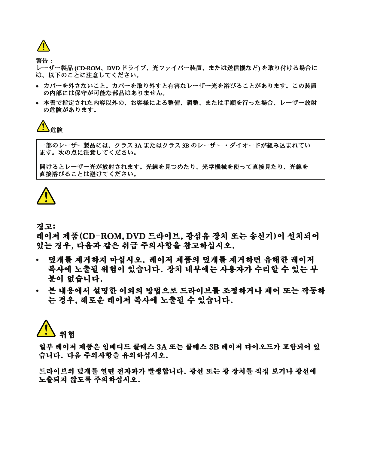
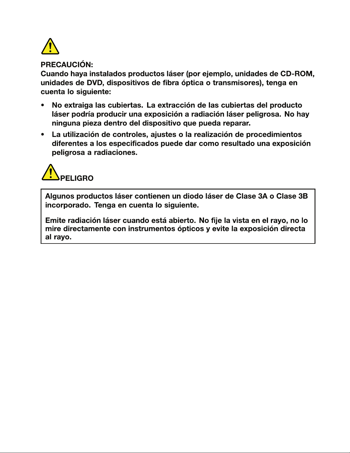
Lasercompliancestatement(multilingualtranslations)
Thelasercompliancestatementsinthissectionareprovidedinthefollowinglanguages:
•English
•Arabic
•BrazilianPortuguese
•French
•German
•Hebrew
•Japanese
•Korean
•Spanish
•T raditionalChinese
Chapter1.Safetyinformation19
Page 26
20HardwareMaintenanceManual
Page 27
Chapter1.Safetyinformation21
Page 28
22HardwareMaintenanceManual
Page 29
Chapter1.Safetyinformation23
Page 30
24HardwareMaintenanceManual
Page 31
Chapter1.Safetyinformation25
Page 32

26HardwareMaintenanceManual
Page 33

Chapter2.Importantserviceinformation
Thischapterpresentsthefollowingimportantserviceinformationthatappliestoallmachinetypessupported
bythismanual:
•“StrategyforreplacingFRUs”onpage27
–“Strategyforreplacingaharddiskdrive”onpage28
–“Importantnoticeforreplacingasystemboard”onpage28
•“ImportantinformationaboutreplacingRoHScompliantFRUs”onpage28
Important:BIOSanddevicedriverxesarecustomer-installable.TheBIOSanddevicedriversareavailable
athttp://www.lenovo.com/support.
StrategyforreplacingFRUs
Beforereplacingparts:
Makesurethatallsoftwarexes,drivers,andBIOSdownloadsareinstalledbeforereplacinganyFRUs
listedinthismanual.
Afterasystemboardisreplaced,ensurethatthelatestBIOSisinstalledtothesystemboardbefore
completingtheserviceaction.
Todownloadsoftwarexes,drivers,andBIOS,dothefollowing:
1.Gotohttp://www.lenovo.com/support.
2.ClickDownloadDrivers&Software.TheWebsiteoffersthreeoptionstobeginyoursearch:
•Searchbyproductnumber
•Searchthroughtheproductauto-detectfunction
•Searchbyproductcategory
3.Followthedirectionsonthescreenandinstallthenecessarysoftware.
Notes:Ifyouneedtoimprovethecomputerperformance,youalsocoulddownloadandinstallthelatest
BIOSutilityfromtheSupportWebsite.
•DonottrytoupdatetheBIOSsettingsforanycomputerunlessyouhavebeentrainedandcertied.An
untrainedpersonrunstheriskofdamagingthecomputer.
•Beforeinstallingthelatestutility,makesurethatthebatteryisfullychargedandanacpoweradapteris
connected.
•Donotturnofforputyourcomputerintosleeporhibernationuntiltheupdatehasbeencompleted.
Otherwise,thesystemboardmightbedamaged.
UsethefollowingstrategytopreventunnecessaryexpenseforreplacingandservicingFRUs:
•IfyouareinstructedtoreplaceaFRUbutthereplacementdoesnotcorrecttheproblem,reinstall
theoriginalFRUbeforeyoucontinue.
•Somecomputershavebothaprocessorboardandasystemboard.Ifyouareinstructedtoreplaceeither
theprocessorboardorthesystemboard,andreplacingoneofthemdoesnotcorrecttheproblem,
reinstallthatboard,andthenreplacetheotherone.
©CopyrightLenovo2012,2013
27
Page 34

•IfanadapteroradeviceconsistsofmorethanoneFRU,anyoftheFRUsmaybethecauseoftheerror.
Beforereplacingtheadapterordevice,removetheFRUs,onebyone,toseeifthesymptomschange.
ReplaceonlytheFRUthatchangedthesymptoms.
Strategyforreplacingaharddiskdrive
Alwaystrytorunalow-levelformatbeforereplacingaharddiskdrive(HDD).Thiswillcauseallcustomerdata
ontheharddisktobelost.Besurethatthecustomerhasacurrentbackupofthedatabeforedoingthistask.
Attention:Thedrivestartupsequenceinthecomputeryouareservicingmayhavebeenchanged.Be
extremelycarefulduringwriteoperationssuchascopying,saving,orformatting.Ifyouselectanincorrect
drive,dataorprogramscanbeoverwritten.
Importantnoticeforreplacingasystemboard
Somecomponentsmountedonasystemboardareverysensitive.Improperhandlingofasystemboardcan
causedamagetothosecomponents,andmaycauseasystemmalfunction.
Attention:Whenhandlingasystemboard:
•Donotdropasystemboardorapplyanyexcessiveforcetoit.
•Avoidroughhandlingofanykind.
•AvoidbendingasystemboardandhardpushingtopreventcrackingateachBGA(BallGridArray)chipset.
ImportantinformationaboutreplacingRoHScompliantFRUs
RoHS,TheRestrictionofHazardousSubstancesinElectricalandElectronicEquipmentDirective
(2002/95/EC)isaEuropeanUnionlegalrequirementaffectingtheglobalelectronicsindustry.RoHS
requirementsmustbeimplementedonLenovoproductsplacedonthemarketafterJune2006.Products
onthemarketbeforeJune2006arenotrequiredtohaveRoHScompliantparts.IftheoriginalFRUparts
arenon-compliant,thereplacementpartsalsocanbenon-compliant.Thatis,iftheoriginalFRUpartsare
RoHScompliant,thereplacementpartalsomustbeRoHScompliant.
Note:RoHSandnon-RoHSFRUpartnumberswiththesametandfunctionareidentiedbytheunique
FRUpartnumbers.
LenovoplanstotransittoRoHScompliancebeforetheimplementationdateandexpectsitssupplierstobe
readytomeetLenovo’srequirementsandscheduleintheEuropeanUnion.Productssoldbetween2005
and2006mightcontainsomeRoHScompliantFRUs.Thefollowingstatementpertainstotheproducts
withRoHScompliantFRUs.
RoHScompliantFRUshaveuniqueFRUpartnumbers.BeforeoraftertheRoHSimplementationdate,the
failedRoHScompliantpartsmustbereplacedwithcompliantpartsandonlythefollowingFRUscanbe
used:identiedascompliantintheHardwareMaintenanceManualordirectsubstitutionscanbeused.
•CompliantFRUsidentiedinHardwareMaintenanceManual
•DirectsubstitutionswithdifferentFRUpartnumbersautomaticallyshippedbythedistributioncenterat
thetimeoforder
ForproductsshippedafterJune2006
Currentororiginalpart
MustbeRoHSMustbeRoHS
28HardwareMaintenanceManual
ReplacementFRU
Page 35

Chapter3.Generalcheckout
Thischapterpresentsfollowinginformation:
•“Whattodorst”onpage29
•“Powersystemcheckout”onpage30
Beforeyougotothecheckoutguide,besuretoreadthefollowingimportantnotes.
Importantnotes:
•Onlycertiedtrainedpersonnelshouldservicethecomputer.
•BeforereplacinganyFRU,readtheentirepageonremovingandreplacingFRUs.
•WhenyoureplaceFRUs,itisrecommendedtousenewnylon-coatedscrews.
•Beextremelycarefulduringsuchwriteoperationsascopying,saving,orformatting.Drivesinthecomputer
thatyouareservicingsequencemighthavebeenaltered.Ifyouselectanincorrectdrive,dataorprograms
mightbeoverwritten.
•ReplaceaFRUonlywithanotherFRUofthecorrectmodel.WhenyoureplaceaFRU,makesurethatthemodel
ofthemachineandtheFRUpartnumberarecorrectbyreferringtotheFRUpartslist.
•AFRUshouldnotbereplacedbecauseofasingle,unreproduciblefailure.Singlefailurescanoccurfora
varietyofreasonsthathavenothingtodowithahardwaredefect,suchascosmicradiation,electrostaticdischarge,
orsoftwareerrors.ConsiderreplacingaFRUonlywhenaproblemrecurs.IfyoususpectthataFRUisdefective,
cleartheerrorlogandrunthetestagain.Iftheerrordoesnotrecur,donotreplacetheFRU.
•BecarefulnottoreplaceanondefectiveFRU.
Whattodorst
WhenyoudoreturnaFRU,youmustincludethefollowinginformationinthepartsexchangeformor
partsreturnformthatyouattachtoit:
1.Nameandphonenumberofservicetechnician
2.Dateofservice
3.Dateonwhichthemachinefailed
4.Dateofpurchase
5.ProcedureindexandpagenumberinwhichthefailingFRUwasdetected
6.FailingFRUnameandpartnumber
7.Machinetype,modelnumber,andserialnumber
8.Customer'snameandaddress
Note:Duringthewarrantyperiod,thecustomermayberesponsibleforrepaircostsifthecomputerdamage
wascausedbymisuse,accident,modication,unsuitablephysicaloroperatingenvironment,orimproper
maintenancebythecustomer.Followingisalistofsomecommonitemsthatarenotcoveredunderwarranty
andsomesymptomsthatmightindicatethatthesystemwassubjectedtostressbeyondnormaluse.
Beforecheckingproblemswiththecomputer,determinewhetherthedamageiscoveredunderthewarranty
byreferringtothefollowinglist:
Thefollowingarenotcoveredunderwarranty:
•LCDpanelcrackedfromtheapplicationofexcessiveforceorfrombeingdropped
•Scratched(cosmetic)parts
•Distortion,deformation,ordiscolorationofthecosmeticparts
•Plasticparts,latches,pins,orconnectorsthathavebeencrackedorbrokenbyexcessiveforce
•Damagecausedbyliquidspilledintothesystem
•DamagecausedbytheimproperinsertionofaPCCardortheinstallationofanincompatiblecard
•Improperdiscinsertionoruseofanopticaldrive
©CopyrightLenovo2012,2013
29
Page 36

•Diskettedrivedamagecausedbypressureonthediskettedrivecover,foreignmaterialinthedrive,
1
2
3
(20V)
ortheinsertionofadiskettewithmultiplelabels
•Damagedorbentdisketteejectbutton
•Fusesblownbyattachmentofanonsupporteddevice
•Forgottencomputerpassword(makingthecomputerunusable)
•Stickykeyscausedbyspillingaliquidontothekeyboard
•Useofanincorrectacpoweradapteronlaptopproducts
Thefollowingsymptomsmightindicatedamagecausedbynonwarrantedactivities:
•Missingpartsmightbeasymptomofunauthorizedserviceormodication.
•Ifthespindleofaharddiskdrivebecomesnoisy,itmayhavebeensubjectedtoexcessiveforce,
ordropped.
Powersystemcheckout
Toverifyasymptom,dothefollowing:
1.Turnoffthecomputer.
2.Removethebatterypack.
3.Connecttheacpoweradapter.
4.Checkthatpowerissuppliedwhenyouturnonthecomputer.
5.Turnoffthecomputer.
6.Disconnecttheacpoweradapterandinstallthechargedbatterypack.
7.Checkthatthebatterypacksuppliespowerwhenyouturnonthecomputer.
Ifyoususpectapowerproblem,seetheappropriateoneofthefollowingpowersupplycheckouts:
•“Checkingtheacpoweradapter”onpage30
•“Checkingoperationalcharging”onpage31
•“Checkingthebatterypack”onpage31
Checkingtheacpoweradapter
Youareherebecausethecomputerfailsonlywhentheacpoweradapterisused.
•Ifthepower-onindicatordoesnotturnon,checkthepowercordoftheacpoweradapterforcorrect
continuityandinstallation.
•Ifthecomputerdoesnotchargeduringoperation,goto“Checkingoperationalcharging”onpage31
Tochecktheacpoweradapter,dothefollowing:
1.Unplugtheacpoweradaptercablefromthecomputer.
2.Measuretheoutputvoltageattheplugoftheacpoweradaptercable.Seethefollowinggure:
Pin
1+20
20
Note:Outputvoltageofpinno.2oftheacpoweradaptermaydifferentfromtheoneyouareservicing.
3.Ifthevoltageisnotcorrect,replacetheacpoweradapter.
4.Ifthevoltageisacceptable,dothefollowing:
•Replacethesystemboard.
•Iftheproblempersists,gotoChapter5“Lenovoproductinformation”onpage37
Voltage(Vdc)
.
30HardwareMaintenanceManual
Page 37

Note:Noisefromtheacpoweradapterdoesnotalwaysindicateadefect.
1(+)
2(+)
3
4
5
6(-)
7(-)
Checkingoperationalcharging
Tocheckwhetherthebatterychargesproperlyduringoperation,useadischargedbatterypackorabattery
packthathaslessthan50%ofthetotalpowerremainingwheninstalledinthecomputer.
Performoperationalcharging.Ifthebatterystatusindicatororicondoesnotturnon,removethebattery
packandletitreturntoroomtemperature.Reinstallthebatterypack.Ifthechargeindicatororiconstilldoes
notturnon,replacethebatterypack.
Ifthechargeindicatorstilldoesnotturnon,replacethesystemboard.Thenreinstallthebatterypack.Ifitis
stillnotcharged,gotothenextsection.
Checkingthebatterypack
Batterychargingdoesnotstartuntilthepowermetershowsthatlessthan95%ofthetotalpowerremains;
underthisconditionthebatterypackcanchargeto100%ofitscapacity.Thisprotectsthebatterypackfrom
beingoverchargedorfromhavingashortenedlife.
Tocheckyourbattery,dependingontheoperatingsystemyouareusing,dothefollowing:
•Windows7:LaunchthePowerManagerprogramandclicktheBatterytab.
•Windows8:
–PresstherecoverybuttontolaunchtheLenovoSolutionCenterprogram,andthenclickSystem
➙Battery.
–OpentheLenovoSettingsprogramfromtheStartscreen,andthenclickPower.
Note:Ifthebatterypackbecomeshot,itmaynotbeabletobecharged.Removeitfromthecomputerand
leaveitatroomtemperatureforawhile.Afteritcoolsdown,reinstallandrechargeit.
Tocheckthebatterypack,dothefollowing:
1.Poweroffthecomputer.
2.Removethebatterypackandmeasurethevoltagebetweenbatteryterminals1(+)and7(-).Seethe
followinggure:
Terminal
1+0to+14
7
3.Ifthevoltageislessthan+11.0Vdc,thebatterypackhasbeendischarged.
Note:Rechargingwilltakeatleast3hours,eveniftheindicatordoesnotturnon.
Ifthevoltageisstilllessthan+11.0Vdcafterrecharging,replacethebattery.
4.Ifthevoltageismorethan+11.0Vdc,measuretheresistancebetweenbatteryterminals5and7.
Theresistancemustbe4to30KΩ.
Voltage(Vdc)
Ground(-)
Chapter3.Generalcheckout31
Page 38

Iftheresistanceisnotcorrect,replacethebatterypack.Iftheresistanceiscorrect,replacethesystem
board.
32HardwareMaintenanceManual
Page 39

Chapter4.Relatedserviceinformation
Thischapterpresentsthefollowinginformation:
•“Recoveringthecomputersettings”onpage33
•“Passwords”onpage33
•“Powermanagement”onpage34
Recoveringthecomputersettings
Thistopicprovidesinformationabouttherecoveryprogramsthatareavailableforyoutorecoverthe
computersettings.
•Windows7:ThefollowingrecoveryprogramsareavailableoncomputerswithaWindows7operating
system:
–OneKey
TheOneKeyRecoveryProprogramenablesyoutobackupallyourharddiskdrivecontents,including
theoperatingsystem,datales,softwareprograms,andpersonalsettings.Y oucandesignatewhere
theOneKeyRecoveryProprogramstoresthebackup.Afteryouhavebackedupthecontentsonthe
harddiskdrive,youcanrestorethecompletecontentsoftheharddiskdrive,restoreonlythedesired
les,orrestoreonlytheWindowsoperatingsystemandapplications.
–ProductRecovery
TheProductRecoveryprogramenablesyoutorestorethecomputersettingstothefactorydefault
settingsthroughrecoverymedia.
®
RecoveryPro
Attention:WhenyouusetheProductRecoveryprogramtorestorethecomputersettings,allthedata
youhavestoredontheharddiskdrivewillbedeletedandthecomputersettingswillberestoredtothe
factorydefaultsettings.Duringtherestoringprocess,youwillbegiventheoptiontosaveoneormore
lescurrentlyontheharddiskdrivetoothermediabeforethedataisdeleted.
•Windows8:ThepreinstalledWindowsrecoveryprogramenablesyoutodothefollowing:
–Refreshingthecomputerwithoutlosingpersonalles
–Restoringthecomputertothefactorydefaultsettings
Attention:WhenyouusetheWindowsrecoveryprogramtorestorethecomputersettings,allthedata
youhavestoredontheharddiskdrivewillbedeletedandthecomputerwillberestoredtothefactory
defaultsettings.T oavoiddataloss,backupyourdatainadvance.
–Conguringtheadvancedstartupoptions
Theadvancedstartupoptionsenableyoutodothefollowing:
–ChangingthestartupsettingsoftheWindowsoperatingsystem
–RestoringtheWindowsoperatingsystemfromasystemimage
–Startingupfromanexternaldevice
Formoreinformationabouttherecoverysolutions,refertothehelpinformationsystemoftheprograms.
Passwords
AsmanyastwopasswordsmightbeneededforaLenovonotebookcomputer:thepower-onpassword
andthesupervisorpassword.
©CopyrightLenovo2012,2013
33
Page 40

Ifanyofthesepasswordshasbeenset,apromptforitwillbedisplayedonthescreenwheneverthe
computeristurnedon.Thecomputerdoesnotstartuntilthepasswordisentered.
Note:Ifonlyasupervisorpasswordisset,thepasswordpromptwillnotbedisplayedwhentheoperating
systemisstarted.
Power-onpassword
Apower-onpasswordprotectsthesystemfrombeingturnedonbyanunauthorizedperson.Thepassword
mustbeenteredbeforeanoperatingsystemcanbestarted.
Supervisorpassword
AsupervisorpasswordprotectsthesysteminformationstoredintheBIOS.Theusermustenterthe
supervisorpasswordtogetaccesstotheBIOSandchangethesystemconguration.
Attention:Ifyouforgetthepassword,thereisnoserviceproceduretoresetthepassword.Thesystem
boardmustbereplacedforascheduledfee.
Powermanagement
Note:PowermanagementmodesarenotsupportedforAPMoperatingsystem.
Toreducepowerconsumption,thecomputerhasthreepowermanagementmodes:screenblank,sleep,
andhibernation.
Screenblankmode
Ifthetimesetonthe“T urnoffmonitor”timerintheoperatingsystemexpires,theLCDbacklightturnsoff.
YoualsocanturnofftheLCDbacklightbypressingFn+F2.
Toendscreenblankmodeandresumenormaloperation,pressanykey.
Sleepmode
Whenthecomputerenterssleepmode,thefollowingeventsoccurinadditiontowhatoccursinscreen
blankmode:
•TheLCDispoweredoff.
•Theharddiskdriveispoweredoff.
•TheCPUstops.
Toentersleepmode,pressFn+F1.
Incertaincircumstances,thecomputergoesintosleepmodeautomatically:
•Ifa“suspendtime”hasbeensetonthetimer,andtheuserdoesnotdoanyoperationwiththekeyboard,
theharddiskdrive,theparallelconnector,orthediskettedrivewithinthattime.
•Ifthebatteryindicatorblinksorange,indicatingthatthebatterypowerislow.
Tocausethecomputertoreturnfromsleepmodeandresumetheoperation,dooneofthefollowing:
•PresstheFnkey.
•OpentheLCDcover.
•T urnonthepowerbutton.
Also,whenthetimesetontheresumetimerelapses,thecomputerautomaticallyreturnsfromsleepmode
andresumesoperation.
34HardwareMaintenanceManual
Page 41

Note:Thecomputerdoesnotacceptanyinputimmediatelyafteritenterssleepmode.Waitafewseconds
beforetakinganyactiontoreenteroperationmode.
Hibernationmode
Inhibernationmode,thefollowingoccurs:
•Thesystemstatus,RAM,VRAM,andsetupdataarestoredontheharddiskdrive.
•Thesystemispoweredoff.
Ifyouhavedenedoneofthefollowingactionsastheeventthatcausesthesystemtogointohibernation
mode,performthataction.
•Closingthelid.
•Pressingthepowerbutton.
Also,thecomputergoesintohibernationmodeautomaticallyineitherofthefollowingconditions:
•Ifa“hibernationtime”hasbeensetonthetimer,andiftheuserdoesnotdoanyoperationwiththe
keyboard,theharddiskdrive,theparallelconnector,orthediskettedrivewithinthattime.
•Ifthetimerconditionsaresatisedinsuspendmode.
Whenthepoweristurnedon,thecomputerreturnsfromhibernationmodeandresumesoperation.The
hibernationleinthebootrecordontheharddiskdriveisread,andsystemstatusisrestoredfromthe
harddiskdrive.
Chapter4.Relatedserviceinformation35
Page 42

36HardwareMaintenanceManual
Page 43

Chapter5.Lenovoproductinformation
Thischapterpresentstheproduct-specicservicereferencesandpartsinformationforthecomputer.
•“Specications”onpage37
•“Statusindicators”onpage38
•“Fnkeycombinations”onpage39
Specications
Thistopicliststhephysicalfeaturesforthecomputer.
Processor
•Windows7:T oviewthesystempropertiesofyourcomputer,clickStart,right-clickComputer;then
clickProperties.
•Windows8:Fromthedesktop,movethecursortothetop-rightorbottom-rightcornerofthescreento
displaythecharms.ThenclickSettings➙PCinfo.
Memory
•Doubledatarate3(DDR3)synchronousdynamicrandomaccessmemory(SDRAM)
Storagedevice
•2.5-inch(7mmheightor9.5mmheight)harddiskdrive
•mSA T Asolidstatedrive(onsomemodelsforcacheonly)
Display
•Size:14.0inches(356mm)
•Resolution:
–LCD:1366-by-768
–Externalmonitor:Maximum2048-by-1536
•Camera
Keyboard
•6-rowLenovokeyboard
•Recoverybutton
Interface
•Comboaudiojack(stereoheadphoneorheadset)
•T woUSB2.0connectors
•T woUSB3.0connectors
•RJ45Ethernetconnector
•HDMIport
•Externalmonitorconnector
•4-in-1digitalmediacardreaderslot
©CopyrightLenovo2012,2013
37
Page 44
Opticaldrive
4
1 2 3
•12.7mmRamboopticaldrive
Wirelessfeatures
•IntegratedwirelessLAN
•100/1000MbpsEthernetcommunication
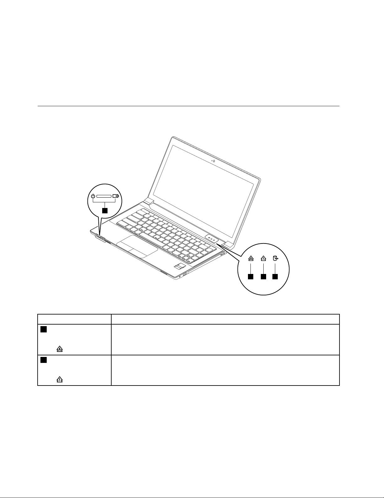
Statusindicators
Thischapterpresentsthesystemstatusindicatorsthatshowthestatusofthecomputer.
Table1.Statusindicators
IndicatorMeaning
1
Capslockstatus
indicator
2
Numericlockstatus
indicator
38HardwareMaintenanceManual
White:CapsLockmodeisenabled.Y oucantypeallalphabeticcharacters(A-Z)in
uppercasedirectly.ToenableordisableCapsLockmode,presstheCapsLockkey.
White:Theseparatenumerickeypadonthekeyboardisenabled.T oenableordisable
thenumerickeypad,presstheNumericLockkey.
Page 45

Table1.Statusindicators(continued)
IndicatorMeaning
3
Deviceaccess
statusindicator
4
Powerandbattery
statusindicator
On:Theharddiskdriveoropticaldriveisreadingorwritingdata.
Attention:
•Whentheindicatorison,donotputthecomputerintosleepmodeorturnoffthe
computer.
•Whentheindicatorison,donotmovethecomputer.Suddenphysicalshockmight
causedriveerrors.
•Solidgreen:Thebatterychargelevelisbetween80%and100%,orthebattery
dischargelevelisbetween20%and100%.
•Slowblinkinggreen:Thebatterychargelevelisbetween20%and80%,and
chargingiscontinuing.Whenthebatterychargelevelreaches80%,thebatterystatus
indicatorstopsblinking,butthechargingmightcontinueuntilthebatteryis100%
charged.
•Slowblinkingorange:Thebatterychargelevelisbetween5%and20%,andthe
chargingiscontinuing.Whenthebatterychargelevelreaches20%,theblinking
colorchangestogreen.
•Solidorange:Thebatterydischargelevelisbetween5%and20%.
•Fastblinkingorange:Thebatterychargeordischargelevelis5%orless.
•Off:Thebatteryisdetachedorthecomputerispoweredoff.
Fnkeycombinations
ThefollowingtabledescribesthefunctionsofFnkeycombinations.
Table2.Functionkeycombinations
KeycombinationDescription
Fn+Esc
Fn+F1Putsthecomputerintosleepmode.T oresumenormaloperation,press
Fn+F2
Fn+F3
Fn+F5
Fn+F6Enablesordisablesthetouchpad.
Fn+F8Enablesordisablesthenumerickeypad.
Fn+F9
Fn+F10
Fn+F11
Fn+F12
Fn+PgUp
Fn+PrtScHasthesamefunctionastheSysRqkeyonaconventionalkeyboard.
•Windows7:Changethecameraandaudiosettings
•Windows8:Turnsonoroffthecamera
theFnkeyonly.
Enablesthebacklightfeatureofthecomputerscreen.Todisablethefeature,
pressFn+F2.
Switchesbetweenthecomputerdisplayandanexternalmonitor.Note:Y ou
alsocanusetheWindows+Pcombinationtoswitchbetweenthecomputer
displayandanexternalmonitor.
Enablesordisablesthebuilt-inwirelessnetworkingfeatures.
Multimediacontrol:Start/Pause
Multimediacontrol:Stop
Multimediacontrol:Skiptotheprevioustrack
Multimediacontrol:Skiptothenexttrack
HasthesamefunctionastheScrLkkeyonaconventionalkeyboard.
Chapter5.Lenovoproductinformation39
Page 46

Table2.Functionkeycombinations(continued)
KeycombinationDescription
Fn+Home
Fn+End
Fn+PgDn
Fn+up/downarrow
Fn+left/rightarrow
HasthesamefunctionasthePausekeyonaconventionalkeyboard.
HasthesamefunctionastheBreakkeyonaconventionalkeyboard.
HasthesamefunctionastheInsertkeyonaconventionalkeyboard.
Increasesordecreasesthedisplaybrightnesslevel.
Decreasesorincreasesthesoundvolume.
40HardwareMaintenanceManual
Page 47

Chapter6.FRUreplacementnotices
Thischapterpresentsnoticesrelatedtoremovingandreplacingparts.Readthischaptercarefullybefore
replacinganyFRU.
CRUstatementforcustomers:
Youcanresolvesomeproblemswithyourproductwithareplacementpartyoucaninstallyourself,called
a“CustomerReplaceableUnit”or“CRU”.SomeCRUsaredesignatedasself-serviceCRUsandothers
aredesignatedasoptional-serviceCRUs.Installationofself-serviceCRUsisyourresponsibility.For
optional-serviceCRUs,youcaneitherinstalltheCRUyourselforyoucanrequestthataServiceProvider
installtheCRUaccordingtothewarrantyserviceforyourproduct.IfyouintendoninstallingtheCRU,
LenovowillshiptheCRUtoyou.CRUinformationandreplacementinstructionsareshippedwithyour
productandareavailablefromLenovoatanytimeuponrequest.Y oucanndalistofCRUsforyour
productinthisHardwareMaintenanceManual.Anelectronicversionofthismanualcanbefoundat
http://www.lenovo.com/UserManuals.Followtheon-screeninstructionstondthemanualforyourproduct.
YoumightberequiredtoreturnthedefectiveCRU.Whenreturnisrequired:(1)returninstructions,aprepaid
shippinglabel,andacontainerwillbeincludedwiththereplacementCRU;and(2)youmightbechargedfor
thereplacementCRUifLenovodoesnotreceivethedefectiveCRUwithinthirty(30)daysofyourreceiptof
thereplacementCRU.SeeyourLenovoLimitedWarrantydocumentationforfulldetails.
Screwnotices
Loosescrewscancauseareliabilityproblem.IntheLenovonotebookcomputer,thisproblemisaddressed
withspecialnylon-coatedscrewsthathavethefollowingcharacteristics:
•Theymaintaintightconnections.
•Theydonoteasilycomeloose,evenwithshockorvibration.
•Theyarehardertotighten.
Dothefollowingwhenyouservicethismachine:
•Keepthescrewkitinyourtoolbag.
•Itisrecommendedtousenewscrews.
•Itrecommendedtouseeachscrewonlyonce.
•Useatorquescrewdriverifyouhaveone.
Tightenscrewsasfollows:
•Plastictoplastic
Turnanadditional90degreesafterthescrewheadtouchesthesurfaceoftheplasticpart:
•Logiccardtoplastic
Turnanadditional180degreesafterthescrewheadtouchesthesurfaceofthelogiccard:
©CopyrightLenovo2012,2013
41
Page 48

•T orquedriver
Ifyouhaveatorquescrewdriver,refertotheT orquecolumninthescrewinformationtableforeachstep.
•Makesurethatyouusethecorrectscrew.Itisrecommendedtousenewscrewsforreplacements.If
youhaveatorquescrewdriver,tightenallscrewsrmlytothetorquespeciedinthescrewinformation
tableforeachstep.
•Ensuretorquescrewdriversarecalibratedcorrectlyfollowingcountryspecications.
42HardwareMaintenanceManual
Page 49

Chapter7.RemovingandreplacingaFRU
ThischapterprovidesinstructionsonhowtoremoveorreplaceaFRU.
CRUstatementforcustomers:
Youcanresolvesomeproblemswithyourproductwithareplacementpartyoucaninstallyourself,called
a“CustomerReplaceableUnit”or“CRU”.SomeCRUsaredesignatedasself-serviceCRUsandothers
aredesignatedasoptional-serviceCRUs.Installationofself-serviceCRUsisyourresponsibility.For
optional-serviceCRUs,youcaneitherinstalltheCRUyourselforyoucanrequestthataServiceProvider
installtheCRUaccordingtothewarrantyserviceforyourproduct.IfyouintendoninstallingtheCRU,
LenovowillshiptheCRUtoyou.CRUinformationandreplacementinstructionsareshippedwithyour
productandareavailablefromLenovoatanytimeuponrequest.Y oucanndalistofCRUsforyour
productinthisHardwareMaintenanceManual.Anelectronicversionofthismanualcanbefoundat
http://www.lenovo.com/UserManuals.Followtheon-screeninstructionstondthemanualforyourproduct.
YoumightberequiredtoreturnthedefectiveCRU.Whenreturnisrequired:(1)returninstructions,aprepaid
shippinglabel,andacontainerwillbeincludedwiththereplacementCRU;and(2)youmightbechargedfor
thereplacementCRUifLenovodoesnotreceivethedefectiveCRUwithinthirty(30)daysofyourreceiptof
thereplacementCRU.SeeyourLenovoLimitedWarrantydocumentationforfulldetails.
Generalguidelines
ThischapterpresentsdirectionsanddrawingsforuseinremovingandreplacingaFRU.Besuretoobserve
thefollowinggeneralrules:
1.Donottrytoserviceanycomputerunlessyouhavebeentrainedandcertied.Anuntrainedpersonruns
theriskofdamagingparts.
2.BeforereplacinganyFRU,reviewChapter6“FRUreplacementnotices”onpage41.
3.BeginbyremovinganyFRUsthathavetoberemovedbeforereplacingthefailingFRU.SuchFRUsare
listedineachFRUreplacementsection.Removethemintheorderinwhichtheyarelisted.
4.FollowthecorrectsequenceinthestepsforremovingaFRU,asgiveninthedrawingsbythenumbers
insquarecallouts.
5.Whenturningascrew,turnitinthedirectionasgivenbythearrowinthedrawing.
6.WhenremovingaFRU,moveitinthedirectionasgivenbythearrowinthedrawing.
7.ToputthenewFRUinplace,reversetheremovalprocedureandfollowanynotesthatpertainto
replacement.
8.WhenreplacingaFRU,usethecorrectscrew(s)asshownintheprocedures.
9.Yourcomputermightlookdifferentlyfromtheillustrationsinthelaterpartofthischapter.
DANGER
BeforeremovinganyFRU,turnoffthecomputer,unplugallpowercordsfromelectricaloutlets,
removethebatterypack,andthendisconnectanyinterconnectingcables.
Attention:AfterreplacingaFRU,donotturnonthecomputeruntilyouhavemadesurethatallscrews,
springs,andothersmallpartsareinplaceandnonearelooseinsidethecomputer.Verifythisbyshaking
thecomputergentlyandlisteningforrattlingsounds.Metallicpartsormetalakescancauseelectrical
shortcircuits.
Attention:Thesystemboardissensitiveto,andcanbedamagedby,electrostaticdischarge.Before
touchingit,establishpersonalgroundingbytouchingagroundpointwithonehandorbyusingan
electrostaticdischarge(ESD)strap(P/N6405959).
©CopyrightLenovo2012,2013
43
Page 50

1010Batterypack
212
1
2
Removalstepsofbatterypack
DANGER
Useonlythebatteryspeciedinthepartslistforyourcomputer .Anyotherbatterycouldignite
orexplode.
Unlockthespring-loadedbatterylatch1.Holdingthemanualbatterylatchintheunlockedposition,remove
thebatterypackinthedirectionshownbythearrow2.
Wheninstalling:Installthebatterypackintheslot.Ensurethatthebatterylatchesareinthelockedposition.
1020Bottomslotcover
Foraccess,removethisFRU:
•“1010Batterypack”onpage44
44HardwareMaintenanceManual
Page 51

Removalstepsofbottomslotcover
1
1
2
2
1
Removethescrews1,andthenremovethecover2.
StepScrew(quantity)Color
1
M2×3mm,at-head,nylon-coated(2)
1030Opticaldrive
Foraccess,removetheseFRUsinorder:
•“1010Batterypack”onpage44
•“1020Bottomslotcover”onpage44
Removalstepsofopticaldrive
Removethescrew1.
Torque
Black
1.85kgf-cm
StepScrew(quantity)Color
1
M2×3mm,at-head,nylon-coated(1)
Torque
Black
Chapter7.RemovingandreplacingaFRU45
1.85kgf-cm
Page 52

Insertascrewdriverintothescrewhole2andpushtheopticaldriveinthedirectionshownbythearrow3.
3
2
1
2
Thenremovetheopticaldrive.
Removalstepsofopticaldrivebezelandopticaldrivebracket
Removethescrew1andthenremovetheopticaldrivebracket.
StepScrew(quantity)Color
1
M2×3mm,at-head,nylon-coated(1)
1040Memorymodules
Foraccess,removetheseFRUsinorder:
•“1010Batterypack”onpage44
•“1020Bottomslotcover”onpage44
Torque
Black
1.85kgf-cm
46HardwareMaintenanceManual
Page 53

Removalstepsofmemorymodules
1
1
2
a
b
Releasethetwolatchesonbothedgesofthesocketatthesametimeinthedirectionshownbythearrows
1,andthenunplugthememorymoduleinthedirectionshownbythearrow2.
Note:Ifonlyonememorymoduleisusedonthecomputeryouareservicing,thecardmustbeinstalledin
SLOT -0(a:lowerslot),butnotinSLOT -1(b:upperslot).
Wheninstalling:Insertthenotchedendofthememorymoduleintothesocket.Pressthememorymodule
rmly,andpivotituntilitsnapsintoplace.Ensurethatitisrmlyinstalledintheslotanddoesnotmoveeasily.
1050Harddiskdriveassembly
Foraccess,removetheseFRUsinorder:
•“1010Batterypack”onpage44
•“1020Bottomslotcover”onpage44
Attention:
•Donotdropthedriveorapplyanyphysicalshocktoit.Thedriveissensitivetophysicalshock.Improper
handlingcancausedamageandpermanentlossofdata.
•Beforeremovingthedrive,havetheusermakeabackupcopyofalltheinformationonitifpossible.
•Neverremovethedrivewhilethecomputerisoperatingorisinsuspendmode.
Chapter7.RemovingandreplacingaFRU47
Page 54

Removalstepsofharddiskdriveassembly
1
2
3
1
1
1
1
Removethescrew1,thenpullthetabinthedirectionshownbythearrow2.
StepScrew(quantity)Color
1
M2×3mm,at-head,nylon-coated(1)
Black
Removetheharddiskdrivefromtheslot3.
Wheninstalling:Makesurethattheharddiskdriveconnectorisattachedrmly.
Removalstepsofharddiskdrivebracket
Removethescrews1.
Torque
1.85kgf-cm
StepScrew(quantity)Color
1
M3×4mm,at-head,nylon-coated(4)Silver
48HardwareMaintenanceManual
Torque
4kgf-cm
Page 55

Removetheharddiskdrivebracketasshownbythearrow2.
2
2
1
1
1060PCIExpressMiniCardforwirelessLAN
Foraccess,removetheseFRUsinorder:
•“1010Batterypack”onpage44
•“1020Bottomslotcover”onpage44
RemovalstepsofPCIExpressMiniCardforwirelessLAN
Insteps1,disconnectthecablesfromthecardusingtheremovaltoolantennaRFconnector(P/N:08K7159)
orpickupthecableswithyourngersandthengentlydisconnectingthecablefromthecardinthedirection
ofthearrows.Thenremovethescrew2.
StepScrew(quantity)Color
2
M2×3mm,at-head,nylon-coated(1)
Torque
Black
Chapter7.RemovingandreplacingaFRU49
1.85kgf-cm
Page 56

Removethecardinthedirectionshownbythearrow3.
3
1
Wheninstalling:Plugtheblackcable(MAIN)intothejacklabeledA,andthewhitecable(AUX)intothejack
labeledBonthecard.
1070mSATAsolid-statedrive
Foraccess,removetheseFRUsinorder:
•“1010Batterypack”onpage44
•“1020Bottomslotcover”onpage44
Attention:
•Donotdropthedriveorapplyanyphysicalshocktoit.Thedriveissensitivetophysicalshock.Improper
handlingcancausedamageandpermanentlossofdata.
•Beforeremovingthedrive,havetheusermakeabackupcopyofalltheinformationonitifpossible.
•Neverremovethedrivewhilethecomputerisoperatingorisinsuspendmode.
RemovalstepsofmSA T Asolid-statedrive
Removethescrew1.
StepScrew(quantity)Color
1
M2×3mm,at-head,nylon-coated(1)
50HardwareMaintenanceManual
Torque
Black
1.85kgf-cm
Page 57

RemovethemSAT Asolid-statedrive2.
2
1
2
1080Backupbattery
Foraccess,removetheseFRUsinorder:
•“1010Batterypack”onpage44
•“1020Bottomslotcover”onpage44
Removalstepsofbackupbattery
DANGER
Useonlythebatteryspeciedinthepartslistforyourcomputer .Anyotherbatterycouldignite
orexplode.
Detachtheconnector1,andthenremovethebatterypackinthedirectionshownbythearrow2.
Wheninstalling:Ensurethattheconnectorisattachedrmly.
1090Keyboard
Foraccess,removetheseFRUsinorder:
•“1010Batterypack”onpage44
•“1020Bottomslotcover”onpage44
Chapter7.RemovingandreplacingaFRU51
Page 58

Removalstepsofkeyboard
1
1
1
2
Removethescrews1.
Wheninstalling:Ensurethatthescrewshavebeenfastenedtosecurethekeyboard.
StepScrew(quantity)Color
1
M2.5×8mm,at-head,nylon-coated(3)
Black
Pushhardinthedirectionshownbythearrow2tounlatchthefrontsideofthekeyboard.
Torque
4.0kgf-cm
Wheninstalling:Ensurethatthekeyboardconnectorisattachedrmly.
52HardwareMaintenanceManual
Page 59

Removethekeyboardinthedirectionshownbythearrow3.
3
Chapter7.RemovingandreplacingaFRU53
Page 60

Carefullyliftthekeyboarduntilyoucanseehowit’sconnected.Holdthekeyboardabovethecomputer4,
5
6
4
andthendetachthekeyboardconnector.
Wheninstalling:Ensurethattheconnectorisattachedrmly.
1100Keyboardbezel
Foraccess,removetheseFRUsinorder:
•“1010Batterypack”onpage44
•“1020Bottomslotcover”onpage44
•“1030Opticaldrive”onpage45
•“1090Keyboard”onpage51
54HardwareMaintenanceManual
Page 61

Removalstepsofkeyboardbezel
2
2
2
1
1
1
1
1
1
1
1
1
1
1
3
Removethescrews1and2thatsecurethekeyboardbezel.
StepScrew(quantity)Color
1
2
M2.5×8mm,at-head,nylon-coated(11)
M2×3mm,at-head,nylon-coated(3)
Removethescrew3.
Torque
Black
Black
4.0kgf-cm
1.85kgf-cm
StepScrew(quantity)Color
3
M2×6mm,at-head,nylon-coated(1)
Black
Chapter7.RemovingandreplacingaFRU55
Torque
1.85kgf-cm
Page 62

Detachtheconnectors.
7
6
9
4
5
10
Wheninstalling:Ensurethatalltheconnectorsareattachedrmly.
Removethekeyboardbezel.
1110LEDboard
Foraccess,removetheseFRUsinorder:
•“1010Batterypack”onpage44
•“1020Bottomslotcover”onpage44
•“1030Opticaldrive”onpage45
56HardwareMaintenanceManual
Page 63

•“1090Keyboard”onpage51
1
2
•“1100Keyboardbezel”onpage54
RemovalstepsofLEDboard
Peeloffthemylartape1..
RemovetheLEDboard2
1120Powerboard
Foraccess,removetheseFRUsinorder:
•“1010Batterypack”onpage44
•“1020Bottomslotcover”onpage44
•“1030Opticaldrive”onpage45
•“1090Keyboard”onpage51
•“1100Keyboardbezel”onpage54
Chapter7.RemovingandreplacingaFRU57
Page 64

Removalstepsofpowerboard
2
1
1
2
Removethescrew1andthenremovethepowerboard2.
StepScrew(quantity)Color
1
M2×3mm,at-head,nylon-coated(1)
Black
Torque
1.85kgf-cm
1130Microphoneassembly
Foraccess,removetheseFRUsinorder:
•“1010Batterypack”onpage44
•“1020Bottomslotcover”onpage44
•“1030Opticaldrive”onpage45
•“1090Keyboard”onpage51
•“1100Keyboardbezel”onpage54
Removalstepsofmicrophoneassembly
Detachtheconnector1,andthenremovethemicrophoneassemblyinthedirectionshownbythearrow2.
Wheninstalling:Ensurethattheconnectorisattachedrmlytothesystemboard.
58HardwareMaintenanceManual
Page 65

1140Mediacardreaderslotboard
1
1
3
2
Foraccess,removetheseFRUsinorder:
•“1010Batterypack”onpage44
•“1020Bottomslotcover”onpage44
•“1030Opticaldrive”onpage45
•“1090Keyboard”onpage51
•“1100Keyboardbezel”onpage54
Removalstepsofthemediacardreaderslotboard
Removethescrews1,andthendetachthecable.
StepScrew(quantity)Color
1
M2×6mm,at-head,nylon-coated(2)
Wheninstalling:Ensurethatthecableisattachedrmlytothesystemboard.
Chapter7.RemovingandreplacingaFRU59
Torque
Black
1.85kgf-cm
Page 66

Removethemediacardreaderslotboard.
4
1150SystemboardassemblyandUSBboard
Importantnoticesforhandlingthesystemboard:
Whenhandlingthesystemboard,bearthefollowinginmind:
•Becarefulnottodropthesystemboardonabenchtopthathasahardsurface,suchasmetal,wood,orcomposite.
•Avoidroughhandlingofanykind.
•Ateverypointintheprocess,besurenottodroporstackthesystemboard.
•Ifyouputasystemboarddown,besuretoputitonlyonapaddedsurfacesuchasanESDmatoracorrugated
conductivesurface.
Foraccess,removetheseFRUsinorder:
•“1010Batterypack”onpage44
•“1020Bottomslotcover”onpage44
•“1030Opticaldrive”onpage45
•“1040Memorymodules”onpage46
•“1050Harddiskdriveassembly”onpage47
•“1060PCIExpressMiniCardforwirelessLAN”onpage49
•“1070mSA T Asolid-statedrive”onpage50
•“1080Backupbattery”onpage51
•“1090Keyboard”onpage51
•“1100Keyboardbezel”onpage54
•“1130Microphoneassembly”onpage58
60HardwareMaintenanceManual
Page 67

RemovalstepsofsystemboardassemblyandUSBboard
1
1
3
4
2
5
8
9
1
7
6
12
10
11
Removethescrews1,andthendetachtheconnectorsasshowninthefollowingillustration.
StepScrew(quantity)Color
1
M2×6mm,at-head,nylon-coated(2)
Black
Torque
1.85kgf-cm
Wheninstalling:Ensurethatalltheconnectorsareattachedrmly.
Removethesystemboardinthedirectionshownbythearrows10and11.ThendetachtheDC-incable12.
Chapter7.RemovingandreplacingaFRU61
Page 68

RemovetheUSBboardasshowninthefollowingillustration.
1160Thermalmodule
Foraccess,removetheseFRUsinorder:
•“1010Batterypack”onpage44
•“1020Bottomslotcover”onpage44
•“1030Opticaldrive”onpage45
•“1040Memorymodules”onpage46
•“1050Harddiskdriveassembly”onpage47
•“1060PCIExpressMiniCardforwirelessLAN”onpage49
•“1070mSA T Asolid-statedrive”onpage50
•“1080Backupbattery”onpage51
•“1090Keyboard”onpage51
•“1100Keyboardbezel”onpage54
•“1130Microphoneassembly”onpage58
•“1150SystemboardassemblyandUSBboard”onpage60
62HardwareMaintenanceManual
Page 69

Removalstepsofthermalmodule
1
3
4
5
2
7
6
8
Detachthefanconnector1.
Wheninstalling:Ensurethattheconnectorisattachedrmly.
Loosenthescrews2to8.
Chapter7.RemovingandreplacingaFRU63
Page 70

Liftthefanassemblyinthedirectionshownbythearrow9.
9
Note:Becarefulnottodamagetheconnector.
64HardwareMaintenanceManual
Page 71

Wheninstalling:Beforeyouattachthethermalmoduletothecomputer,applythermalgrease,atanamount
a
b
a
of0.2grams,onthepartmarkedaandbasshowninthefollowingillustrations.Eithertoomuchortooless
applicationofgreasecancauseathermalproblemduetoimperfectcontactwithacomponent.
Formodelswithadiscretethermalmodule
Formodelswithanintegratedthermalmodule
1170Microprocessor
Foraccess,removetheseFRUsinorder:
•“1010Batterypack”onpage44
•“1020Bottomslotcover”onpage44
•“1030Opticaldrive”onpage45
•“1040Memorymodules”onpage46
•“1050Harddiskdriveassembly”onpage47
•“1060PCIExpressMiniCardforwirelessLAN”onpage49
•“1070mSA T Asolid-statedrive”onpage50
•“1080Backupbattery”onpage51
•“1090Keyboard”onpage51
Chapter7.RemovingandreplacingaFRU65
Page 72

•“1100Keyboardbezel”onpage54
22
a
b
1
•“1130Microphoneassembly”onpage58
•“1150SystemboardassemblyandUSBboard”onpage60
•“1160Thermalmodule”onpage62
Attention:Themicroprocessorisextremelysensitive.Whenyouservicethemicroprocessor,avoidany
kindofroughhandling.
Removalstepsofmicroprocessor
Rotatetheheadofthescrewinthedirectionshownbythearrow1toreleasethelock,thenremovethe
microprocessor2.
Wheninstalling:Placethemicroprocessorabovethemicroprocessorsocketa,andthenrotatetheheadof
thescrewinthedirectionshownbythearrowbtosecurethemicroprocessor.
1180LCDunit
Foraccess,removetheseFRUsinorder:
•“1010Batterypack”onpage44
•“1020Bottomslotcover”onpage44
•“1030Opticaldrive”onpage45
•“1040Memorymodules”onpage46
•“1050Harddiskdriveassembly”onpage47
•“1060PCIExpressMiniCardforwirelessLAN”onpage49
•“1070mSA T Asolid-statedrive”onpage50
•“1080Backupbattery”onpage51
•“1090Keyboard”onpage51
•“1100Keyboardbezel”onpage54
66HardwareMaintenanceManual
Page 73

•“1130Microphoneassembly”onpage58
1
1
1
1
•“1140Mediacardreaderslotboard”onpage59
•“1150SystemboardassemblyandUSBboard”onpage60
RemovalstepsofLCDunit
Releasetheantennacablesfromthecableguides.Thenremovethescrews1.
StepScrew(quantity)Color
1
M2.5×6mm,at-head,nylon-coated(4)Silver
Torque
4.0kgf-cm
Wheninstalling:
•Routetheantennacablesalongthecableguides.Asyouroutethecables,makesurethattheyare
notsubjectedtoanytension.Tensioncouldcausethecablestobedamagedbythecableguides,
orawiretobebroken.
•EnsurethattheLCDconnectorisattachedrmlyandmakesurethatyoudonotpinchtheantennacables
whenyouattachtheLCDassembly.RoutetheLCDcablealongthecableguides.
Chapter7.RemovingandreplacingaFRU67
Page 74
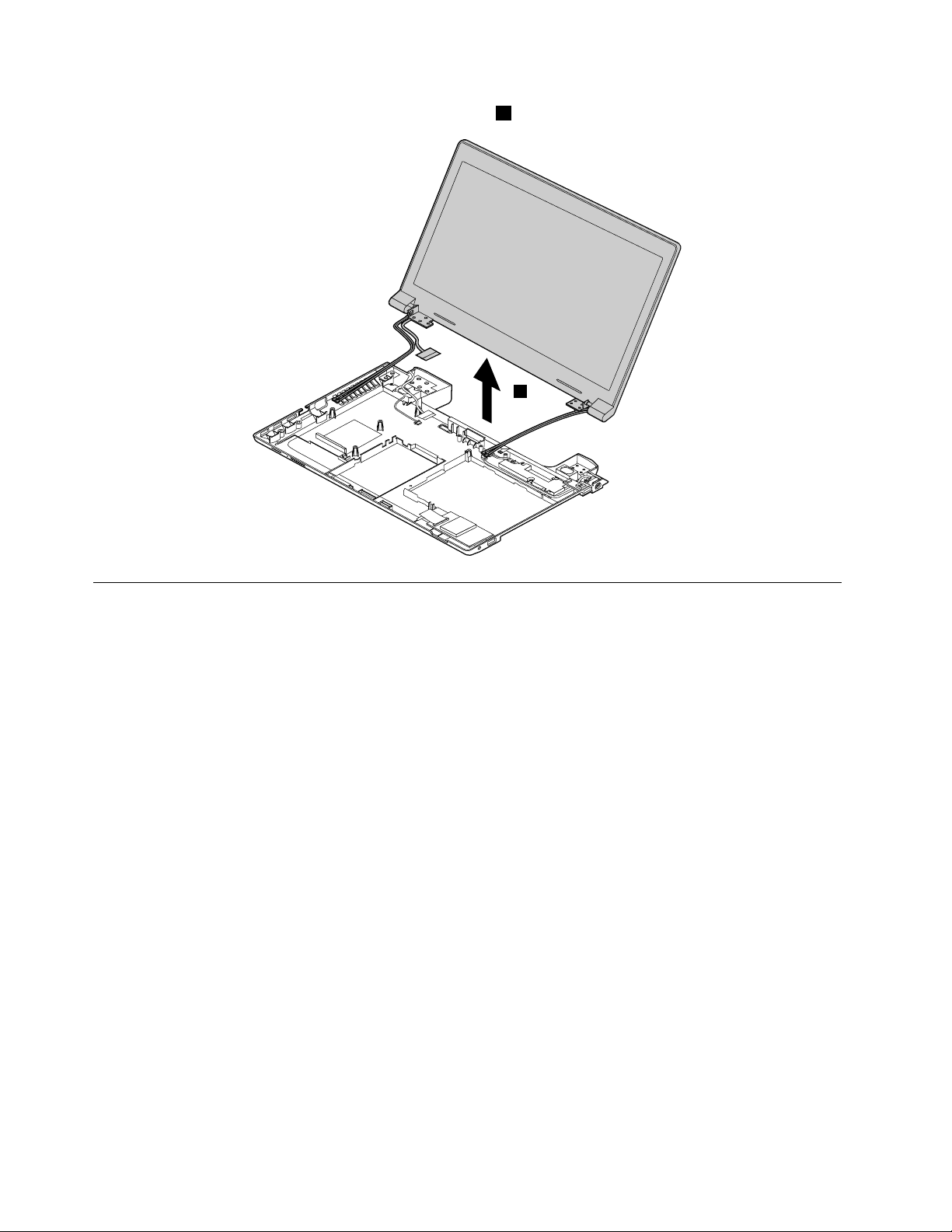
RemovetheLCDunitinthedirectionshownbythearrow2.
2
1190Speakerassembly
Foraccess,removetheseFRUsinorder:
•“1010Batterypack”onpage44
•“1020Bottomslotcover”onpage44
•“1030Opticaldrive”onpage45
•“1040Memorymodules”onpage46
•“1050Harddiskdriveassembly”onpage47
•“1060PCIExpressMiniCardforwirelessLAN”onpage49
•“1070mSA T Asolid-statedrive”onpage50
•“1080Backupbattery”onpage51
•“1090Keyboard”onpage51
•“1100Keyboardbezel”onpage54
•“1130Microphoneassembly”onpage58
•“1140Mediacardreaderslotboard”onpage59
•“1150SystemboardassemblyandUSBboard”onpage60
•“1180LCDunit”onpage66
68HardwareMaintenanceManual
Page 75

Removalstepsofspeakerassembly
2
1
1
2
1
1
Removethescrews1.Thenremovethespeakerassembly2.
StepScrew(quantity)Color
1
M2.5×5.7mm,at-head,nylon-coated(4)
1200DC-inconnectorandbasecover
Foraccess,removetheseFRUsinorder:
•“1010Batterypack”onpage44
•“1020Bottomslotcover”onpage44
•“1030Opticaldrive”onpage45
•“1040Memorymodules”onpage46
•“1050Harddiskdriveassembly”onpage47
•“1060PCIExpressMiniCardforwirelessLAN”onpage49
•“1070mSA T Asolid-statedrive”onpage50
•“1080Backupbattery”onpage51
•“1090Keyboard”onpage51
•“1100Keyboardbezel”onpage54
•“1130Microphoneassembly”onpage58
•“1140Mediacardreaderslotboard”onpage59
•“1150SystemboardassemblyandUSBboard”onpage60
•“1180LCDunit”onpage66
•“1190Speakerassembly”onpage68
Torque
Black
4.0kgf-cm
Chapter7.RemovingandreplacingaFRU69
Page 76

RemovalstepsofDC-inconnectorandbasecover
2
1
1
Removethescrews1,andthenremovetheDC-inconnectorinthedirectionshownbythearrow2.
StepScrew(quantity)Color
1
M2×3mm,at-head,nylon-coated(2)
Black
Torque
1.85kgf-cm
Applyinglabelstothebasecover
Thenewbasecoverisshippedwithakitcontaininglabelsofseveralkinds.Applythoselabelslistedwhen
youreplacethebasecover.Forthelabelswhicharenotshippedwiththenewbasecover,peelthemoff
fromtheoldbasecover,andadherethemtothenewone.
Note:IfyoureplaceapartwiththeWindowsCerticateofAuthentication(COA)label12,returntheoldpart
withthelabelattachedtothecustomer.Otherwise,youcanprovidethecustomerwithaletter,statingthe
originallocationofthelabelonthecomputerandtheinformationonthelabel,suchasthepartnumber,
serialnumber,andproductkey.
Thefollowingillustrationshowsthecorrectlocationofeachlabel.
70HardwareMaintenanceManual
Page 77
11
12
7
8
9
2
4
10
6
3
5
1
13
14
1IndonesiaDsidelabel8Israellabel
2WirelessWANIMEIbarcodelabel9Israellabel
3BrazilBluetoothlabel/BluetoothlabelforUnited
10MalaysiaSIRIMlabel
States/Canada/T aiwan
4PRC/MTMlabel/KCClabel/Mexicolabel/MAClabel
5BrazilWirelessLANlabel/WLANlabelforUS/CA/TW
6PPTlabel
7IndonesiaWLANandBTlabel14Ratinglabel
11Vodafonelabel
13Ratinglabel
12WindowsCerticateofAuthentication(COA)label
2010LCDfrontbezel
Foraccess,removetheseFRUsinorder:
•“1010Batterypack”onpage44
•“1180LCDunit”onpage66
Chapter7.RemovingandreplacingaFRU71
Page 78

RemovalstepsofLCDfrontbezel
1
1
2
2
2
2
Removethescrews1.
StepScrew(quantity)Color
1
M2×3.5mm,at-head,nylon-coated(2)
RemovetheLCDfrontbezelinthedirectionshownbythearrows2.
Torque
Black
1.85kgf-cm
Wheninstalling:Ensurethatallthelatchesareattachedrmly.Thensecurethebezelwiththescrews.
2020Camera
Foraccess,removetheseFRUsinorder:
•“1010Batterypack”onpage44
•“1180LCDunit”onpage66
•“2010LCDfrontbezel”onpage71
72HardwareMaintenanceManual
Page 79
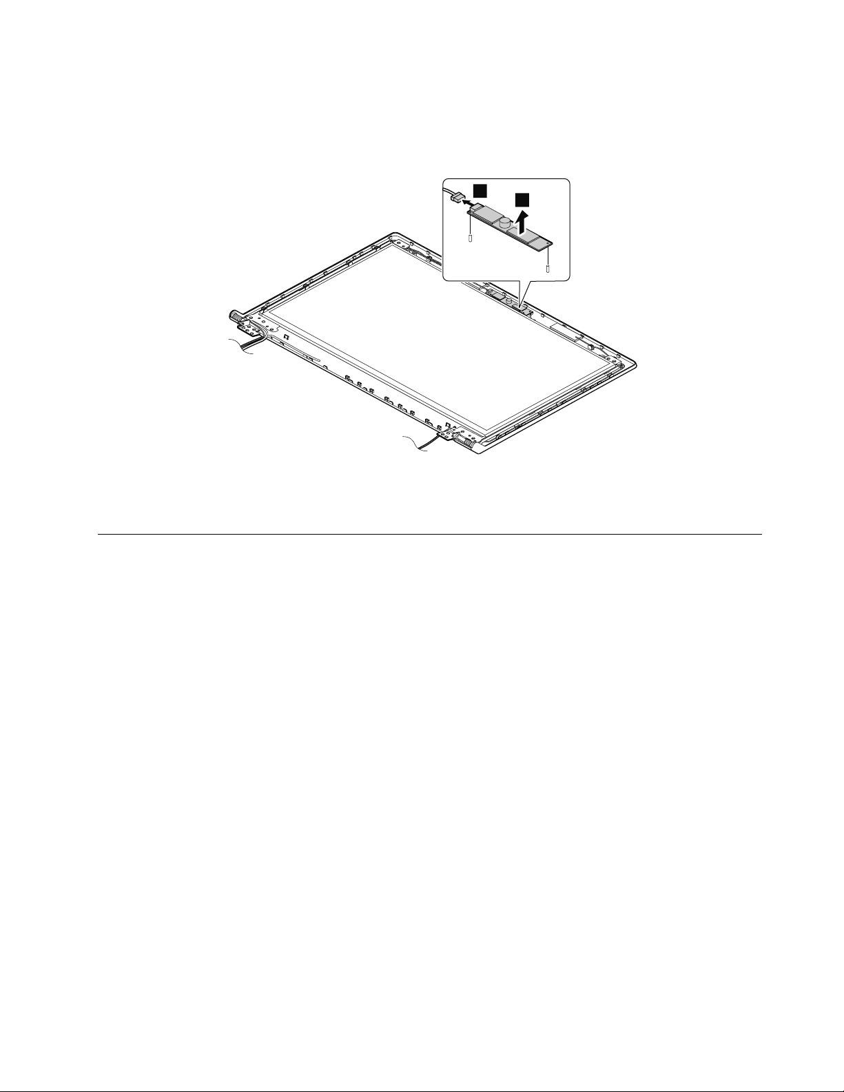
Removalstepsofcamera
1
2
RemovethecamerafromtheLCDcoverasshowninthefollowingillustration.
Note:ThecameraisstuckonthetopcenteroftheLCDcover.
Wheninstalling:StickthecameratothetopcenteroftheLCDcoverandadjusttheplacementtomakesure
thattheconnectorisattachedrmly.
2030LCDpanel,LCDcable,andhinges
Foraccess,removetheseFRUsinorder:
•“1010Batterypack”onpage44
•“1180LCDunit”onpage66
•“2010LCDfrontbezel”onpage71
Chapter7.RemovingandreplacingaFRU73
Page 80

RemovalstepsofLCDpanelandLCDcable
1
1
1
1
2
1
1
4
3
3
3
3
4
Removethescrews1.ThenremovetheLCDpanelwithhingesinthedirectionshownbythearrow2.
StepScrew(quantity)Color
1
M2×4mm,at-head,nylon-coated(6)
White
Torque
1.85kgf-cm
Removethescrews3.Thenremovethehinges4.
StepScrew(quantity)Color
3
M2×2.5mm,at-head,nylon-coated(4)
White
Torque
1.85kgf-cm
74HardwareMaintenanceManual
Page 81

RemovetheLCDcable.
1
2
1
1
Wheninstalling:Ensurethatthecableisattachedrmly.
2040AntennaassemblyandLCDrearcover
Foraccess,removetheseFRUsinorder:
•“1010Batterypack”onpage44
•“1180LCDunit”onpage66
•“2010LCDfrontbezel”onpage71
•“2020Camera”onpage72
•“2030LCDpanel,LCDcable,andhinges”onpage73
RemovalstepsofantennaassemblyandLCDrearcover
ReleasetheantennacablesfromthecableguidesoftheLCDrearcoverassemblyandfromthehingesin
thedirectionshownbythearrows1.
Cablerouting:Routetheantennacablesalongthecableguidesandsecuretheantennaboardswith
adhesivetapes.Asyouroutethecables,makesurethattheyarenotsubjectedtoanytension.Tension
couldcausethecablestobedamagedbythecableguides,orawiretobebroken.
Chapter7.RemovingandreplacingaFRU75
Page 82

76HardwareMaintenanceManual
Page 83

Chapter8.Locations
2
1
2
9
8
4
3
4
5
7
6
Thischapterpresentsthelocationsofthehardwarecomponents.
Frontview
Figure1.Frontview
1Integratedcamera(onsomemodels)
2Wirelessmoduleantennas7Powerandbatterystatusindicator
3Statusindicators
4Speakers
5Mediacardreaderslot
1
Forthedescriptionoftheindicators,see“Statusindicators”onpage38.
©CopyrightLenovo2012,2013
1
6Touchpadandtouchpadbuttons
1
8Powerbutton
9Recoverybutton
77
Page 84

Right-sideview
1
2
3
4
5
4
5
6
7
8
10
9
1
2
3
Figure2.Right-sideview
1Comboaudiojack4USBconnector
2USBconnector
3Opticaldrive
5acpowerconnector
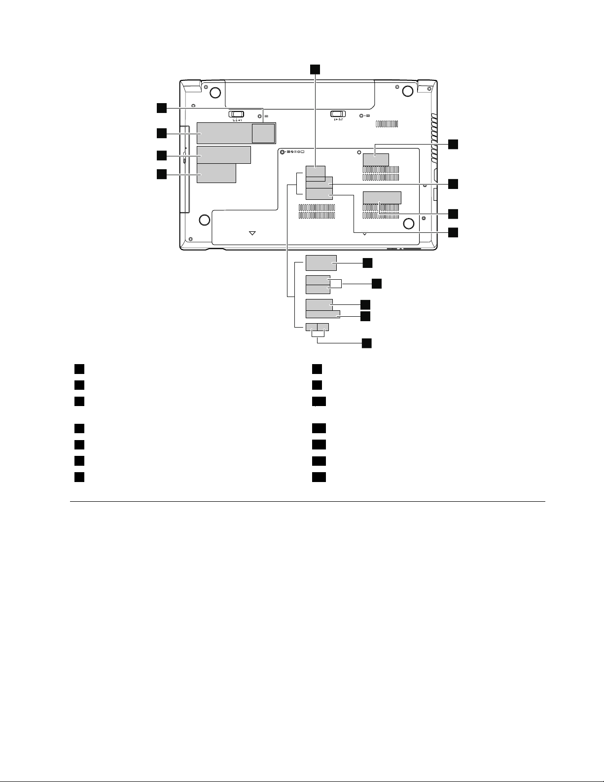
Bottomandleft-sideview
Figure3.Bottomandleft-sideview
1Batterylatch6Monitorconnector
2Batterypack7Ethernetconnector
3Batterylock8HDMIport
4Securitykeyhole9USBconnectors
5Fanlouvers10Bottomslotcover
1
Thememorymodules,harddiskdrive,andwirelesscardsarelocatedunderneaththebottomslotcover.
1
78HardwareMaintenanceManual
Page 85

Chapter9.Partslist
Thischaptercontainsfollowinglistsoftheserviceparts.
•“Overall”onpage80
•“LCDFRUs”onpage84
•“Keyboard”onpage86
•“Miscellaneousparts”onpage89
•“acpoweradapters”onpage89
•“Powercords”onpage91
Notes:
•EachFRUisavailableforalltypesormodels,unlessotherwisespecied.
•ACRUisidentiedbyasingleasterisk(*)ortwoasterisks(**)intheCRUIDcolumn.AnNintheCRUIDcolumn
meansthatthepartisnotaCRU.Asingleasterisk(*)meansthatthepartisaself-serviceCRU;twoasterisks
(**)meansthatthepartisanoptional-serviceCRU.
CRUstatementforcustomers:
Youcanresolvesomeproblemswithyourproductwithareplacementpartyoucaninstallyourself,calleda
“CustomerReplaceableUnit”or“CRU”.SomeCRUsaredesignatedasself-serviceCRUsandothersare
designatedasoptional-serviceCRUs.Installationofself-serviceCRUsisyourresponsibility.Foroptional-service
CRUs,youcaneitherinstalltheCRUyourselforyoucanrequestthataServiceProviderinstalltheCRUaccording
tothewarrantyserviceforyourproduct.IfyouintendoninstallingtheCRU,LenovowillshiptheCRUtoyou.CRU
informationandreplacementinstructionsareshippedwithyourproductandareavailablefromLenovoatanytime
uponrequest.Y oucanndalistofCRUsforyourproductinthisHardwareMaintenanceManual.Anelectronic
versionofthismanualcanbefoundathttp://www.lenovo.com/UserManuals.Followtheon-screeninstructionsto
ndthemanualforyourproduct.Y oumightberequiredtoreturnthedefectiveCRU.Whenreturnisrequired:(1)
returninstructions,aprepaidshippinglabel,andacontainerwillbeincludedwiththereplacementCRU;and(2)you
mightbechargedforthereplacementCRUifLenovodoesnotreceivethedefectiveCRUwithinthirty(30)daysof
yourreceiptofthereplacementCRU.SeeyourLenovoLimitedWarrantydocumentationforfulldetails.
LenovocomputerscontainthefollowingtypesofCRUs:
–Self-serviceCRUs:TheseCRUsunplugorareheldbynomorethantwoscrews.Examplesofthesetypes
ofCRUsincludetheacpoweradapter,powercord,battery,andharddiskdrive.Otherself-serviceCRUs
dependingonproductdesignmightincludethememorymodule,wirelesscard,keyboard,andpalmrest
withngerprintreaderandtouchpad.
–Optional-serviceCRUs:TheseCRUsareisolatedpartswithinthecomputerthatareconcealedbyanaccess
panelthatistypicallysecuredbymorethantwoscrews.Oncetheaccesspanelisremoved,thespecic
CRUisvisible.
©CopyrightLenovo2012,2013
79
Page 86

Overall
1
2
3
5
6
7
10
d
9
c
8
11
e
12
13
14
15
f
17
18
21
g
h
23
b
20
19
16
22
1
2
3
4
5
6
7
8
c
e
f
g
d
a
b
9
10
11
12
13
14
15
16
17
18
19
20
21
22
Table3.Partslist—Overall
No.
FRU(Overall)
1
LCDunit(see“LCDFRUs”onpage84.)
2
LB48UpperCaseW/TP6M.4TFCS.001
2
KeyboardbezelforBrazil,withoutngerprintreader
80HardwareMaintenanceManual
FRUno.
90200759N
04X1157N
CRU
ID
Page 87

Table3.Partslist—Overall(continued)
No.
FRU(Overall)
2
KeyboardbezelforBrazil,withngerprintreader
3
LB48LEDBoardW/Cable50.4TF03.001
4
Thermalmodule,DIS
4Thermalmodule,UMA90201842
5
LB49AUSBBoardW/Cable
5
LB49BUSBBoardW/Cable
5
USBboardforBrazil,withcable
6
Battery,6cell,2.2Ah,Sanyo
6
Battery,6cell,2.2Ah,LG
6
Battery,6cell,2.2Ah,Sony
6
Battery,6cell2.2Ah,SMP
6
Battery,6cell,2.8Ah,LGL11L6F013S2P62WhBattC01Origa
6
Battery,6cell,2.8Ah,SM/SL11M6F013S2P62WhBattC01Origa
7
LA48DCINLENS60.4TD25.001
8
Speaker(right)
9Basecover90200529
10
Opticaldrive,12.7mmT ray-inRambo,PLDS
10
Opticaldrive,12.7mmT ray-inRambo,SonyOptiarc
10
Opticaldrive,12.7mmT ray-inRambo,TSST
10
Opticaldrive,12.7mmT ray-inRambo,HLDS
11
WirelessLANcard,Non-Intel1x111bgn+BT4.0Combo,Broadcom4313+20702
11
WirelessLANcard,Non-Intel2x211abgn+BT4.0Combo,Broadcom43228+20702
11
WirelessLANcard,Intel2x211bgn+BT4.0Combo,JacksonPeak1
11
WirelessLANcard,Non-Intel1x111bgn,BroadcomBCM43131*1BGNMOW
11
WirelessLANcard,Non-Intel1x111bgn+BT4.0Combo
FRUno.
04X1158N
90000223N
90201841
04X1096
04X1098
04X1097
04X1099
90000969N
90000976N
04X1161N
121500047
45N1043
121500049
45N1049
45N1047*
121500050
45N1045
121500052*
121500053*
90200533N
90200535
04X1176
04X1173
25201487
04X1194
25201106
04X1196
25201108
04X1197
25201635
04X1198
20200100
20200101
04W3761
04W3762
20200098
20200099
20200078*
20200102
04W3750
04W3794
04W3795
CRU
ID
N
N
*
*
*
N
N
*
*
*
*
*
*
*
*
Chapter9.Partslist81
Page 88

Table3.Partslist—Overall(continued)
No.
FRU(Overall)
11
WirelessLANcard,Non-Intel1x111bgn,Realtekbgn1x1HMCWLANStockton
12
Solidstatedrive,mSATA16G,Sandisk,U100mSATASDSA5DK-016G
13Mediacardreaderboardwithcable90000222
14Bottomslotcover90200528
15
SATAharddiskdrive,320G5400rpm,ToshibaCapricornBS(H6sp),ToshibaMK3265GSX
15
SATAharddiskdrive,320G5400rpm,HGSTJaquarB7,HGSTHTS545032A7E380,7-mm
height
15
SATAharddiskdrive,320G5400rpm,SeagateSapta15,SeagateST320L T020,7-mm
height
15
SATAharddiskdrive,500G5400rpm,WDML500M,WD5000BPVT -08A1Y
15
SATAharddiskdrive,500G5400rpm,WDML375M,WD5000BPVT -08HXZ
15
SATAharddiskdrive,500G5400rpm,ToshibaCapricornBS(H6sp)
15
SATAharddiskdriveforBrazil,500G5400rpm
15
SATAharddiskdrive,750G5400rpm,WDML500M
15
SATAharddiskdrive,750G5400rpm,WDML375M
15
SATAharddiskdrive,750G5400rpm,HGSTJaguarB,HTS541075A9E680
15
SATAharddiskdrive,1TB5400rpm,WDML500M
15
SATAharddiskdrive,1TB5400rpm,HGSTJaquarB,HTS541010A9E680
15
SATAharddiskdrive,320G7200rpm,WDMX320S-1
15
SATAharddiskdrive,320G7200rpm,ToshibaCapricornCS(H6sp),TSBMK3261GSY ,
9.5-mmheight
15
SATAharddiskdrive,320G7200rpm,HGSTJaquarC7,HTS725032A7E630
15
SATAharddiskdrive,320G7200rpm,SeagateJulius14K,7-mmheight
15
SATAharddiskdrive,500G7200rpm,WDMX375M
15
SATAharddiskdrive,500G7200rpm,T oshibaCapricornCS(H6sp),9.5-mmheight
15
SATAharddiskdrive,500G7200rpm,JaguarC7,HTS725050A7E630
16
Speaker(left)
17
MemoryModule,DDRIII16002GB
17
MemoryModule,DDRIII16002GB,Samsung,M471B5773DH0-CK0
17
MemoryModule,DDRIII16002GB,Hynix,HMT325S6CFR8C-PB
17
MemoryModule,DDRIII16002GB,Micron,MT8KTF25664HZ-1G6M1
17
MemoryModule,DDRIII16002GB,Ramaxel,RMT3150ED58E8W-1600
FRUno.
20200016
60Y3249
16200215N
04X1160
04X1159
16200097**
16200068**
16005211**
16200118**
16200090**
16200098**
04X1190
04X1191
04X1183
04X1184
04X1185
04X1187
16200119**
16200121**
16200192**
16200120**
16200193**
16200092**
16200099**
16200194**
16005030**
16200124**
16200100**
16200195**
90200536
04X1172
03X6560*
11200340*
11200343*
11200346*
11200392*
CRU
ID
*
N
N
**
**
82HardwareMaintenanceManual
Page 89

Table3.Partslist—Overall(continued)
No.
FRU(Overall)
17
MemoryModule,DDRIII16002GB,Sharetronic(Micron),SM321NH08IAF
17
MemoryModule,DDRIII16004GB
17
MemoryModule,DDRIII16004GB,Samsung,M471B5273DH0-CK0
17
MemoryModule,DDRIII16004GB,Hynix,HMT351S6CFR8C-PB
17
MemoryModule,DDRIII16004GB,Micron,MT16KTF51264HZ-1G6M1
17
MemoryModule,DDRIII16004GB,Ramaxel,RMT3160ED58E9W-1600
17
MemoryModule,DDRIII16004GB,Sharetronic(Micron),SM322NQ08IAF
FRUno.
11200396*
03X6561*
11200341*
11200344*
11200347*
11200393*
11200397*
18LB48Micphone23.42384.00190200766N
19
LB49AMBUMAWO/SBAW/HDMI
19
LB49AMBDISN13M-GE11GWO/SBA
19
LB49AMBDISN13M-GE1512WO/SBA
19
LB49AMBW8UMAWO/SBAW/HDMI
19
LB49AMBW8PUMAWO/SBAW/HDMI
19
LB49AMBW8DISN13M-GE11GWO/SBA
19
LB49AMBW8PDISN13M-GE11GWO/SBA
19
LB49AMBW8DISN13M-GE1512WO/SBA
19
LB49AMBW8PDISN13M-GE1512WO/SBA
19
LB49BMBW8UMAWO/SBAW/HDMI
19
LB49BMBW8PUMAWO/SBAW/HDMI
19
LB49BMBW8DISN13M-GE11GWO/SBA
19
LB49BMBW8PDISN13M-GE11GWO/SBA
19
LB49BMBW8DISN13P-GL1GW/SBA
19
LB49BMBW8PDISN13P-GL1GW/SBA
19
LB49BMBDISN13M-GE11GW/SBA
19
LB49BMBUMAW/SBA
19
LB49BMBDISGLRW/SBA
19
LB49BMBW8DISN13M-GE11GW/SBA
19
LB49BMBW8PDISN13M-GE11GW/SBA
19
LB49BMBW8UMAW/SBA
19
LB49BMBW8PUMAW/SBA
19
LB49BMBW8DISGLRW/SBA
19
LB49BMBW8PDISGLRW/SBA
19
SystemboardassemblyforBrazil,Windows7,IntelHM77,integrated,withSmallBusiness
90000973N
90000974N
90000975N
90001824N
90001825N
90001826N
90001827N
90001828N
90001829N
90001830N
90001831N
90001832N
90001833N
90001834N
90001835N
90001919N
90001920N
90001921N
90001932N
90001933N
90001934N
90001935N
90001936N
90001937N
04X1053N
Advantage
19
SystemboardassemblyforBrazil,Windows7,IntelHM77,integrated,withoutSmall
04X1177N
BusinessAdvantage
19
SystemboardassemblyforBrazil,Windows8,IntelHM77,integrated,withSmallBusiness
04X1054N
Advantage
CRU
ID
Chapter9.Partslist83
Page 90

Table3.Partslist—Overall(continued)
No.
FRU(Overall)
19
SystemboardassemblyforBrazil,Windows8,IntelHM77,integrated,withoutSmall
BusinessAdvantage
20
CPU,IntelI5-2520M,2.5G,3M,2cJ1PGAprocessor
20
CPU,IntelB815,1.6G,Q0,2M2cPGAprocessor
20
CPU,IntelI3-2370M,2.4G,J1,3M,2cPGAprocessor
20
CPU,IntelSNBI3-2350M2.3G3MJ1PGAprocessor
20
CPU,IntelSNBI3-2330M,2.2G,3M,J1PGAprocessor
20
CPU,IntelSNBB950,2.1G,2M,Q0,PGAprocessor
20
CPU,IntelSNBB940,2.0G,2M,Q0,PGAprocessor
20
CPU,IntelSNBI3-2310M,2.1G,3M,2cJ1PGAprocessor
20
CPU,IntelB970,2.3G,D2,2M,2cPGAprocessor
20
CPU,IntelSNBB800,1.5G,Q0,2M,2cPGAprocessor
20
CPU,IntelSNBB960,2.2G,2M,35W,PGAprocessor
20
CPU,IntelB820,1.7G,Q0,2M,2cPGAprocessor
20
CPU,i5-3210MIvyBridgeL -03MB2cPGA2.5GHzSTD35Wprocessor
20
CPU,i3-3110MIvyBridgeL -03MB2cPGA2.3GHzSTD35Wprocessor
20
CPU,IntelB980,2.4G,Q0,2M,2cPGAProcessor
20
CPU,IntelB830,1.8G,Q0,2M,2cPGAProcessor
20
CPU,Intel2020M,2.4G,L1,2M,2cPGAProcessor
20
CPU,IntelI3-2328M,2.2G,J1,3M,2cPGA
20
CPU,IntelI3-3120M,2.5G,L1,3M,2cPGAProcessor
22Powerboard90000220
22
Keyboard(see“Keyboard”onpage86.)
—
DC-inconnectorwithbracket
—
Fingerprintreaderboardwithcable90000221
—
BackupbatteryforBrazil
—
CamerawithmicrophoneforBrazil
—
acpoweradapter(see“acpoweradapters”onpage89.)
FRUno.
04X1178N
102001067N
102500229N
102500228N
102500018N
102500017N
102500016N
102500015N
102001065N
102500230N
102500101N
102500133N
102500350N
102500301N
102500303N
102500362N
102500440N
102500433N
102500421N
102500435N
04X1163
04X1162N
04X1165
04X1174*
04W2671
04W2670
04W2672
CRU
ID
N
N
N
LCDFRUs
ThetypeofLCDis14-inchhighdenition(HD)TFTLCD(T able4“Partslist-LCD”onpage85).
84HardwareMaintenanceManual
Page 91

i
7
1
2
3
4
5
6
Table4.Partslist-LCD
No.FRUFRUno.
CRU
ID
1
LB49ALCDBezelW/CameraHole
1
LB49ALCDBezelWO/CameraHole
1
LCDbezelforBrazil
2Hinges90200760
90201838N
90201839N
04X1168N
N
04X1171
3
LB58Camera0.3M
90000238N
4LB48AntennaR25.90AAL.00190200764N
5
LCDcover
90201835
N
04X1167
6LB48AntennaL25.90AAK.00190200763N
7
Panel,14.0HDAUO
18200207
N
04W4006
Chapter9.Partslist85
Page 92

Table4.Partslist-LCD(continued)
No.FRUFRUno.
7
PanelforBrazil,14.0HD
7
Panel,14.0HD,BOEHB140WX1-100
7
Panel,14.0HD,SECLTN140AT26-L01
7
Panel,14.0HD,LGDLP140WH4-TLN1
7
Panel,14.0HD,IVOM140NWR2R1
7
PanelforBrazil,14.0'',antiglare
7
PanelforBrazil,14.0'',glare
—
WirelessLANantennasetforBrazil
Keyboard
Table5.Partslist-Keyboard(Brazil)
04W4008
04W4023
04W4007
04W4064
04X1910
18200154N
18200229N
18200156N
18004793N
04X1100N
04X1101N
04X1169N
CRU
ID
N
Language
BrazilianPortuguese25204447
Table6.Partslist-Keyboard(Dafon)
Language
Arabic2520444625209346N
Belgian2520445425209354N
Bulgarian2520446025209360N
French,English2520444025209340N
Czech,Slovak
C&Nordics
Dutch2520444925209349N
French2520444425209344N
German
Greek
Hebrew2520445125209351N
Hungarian2520445225209352N
Icelandic2520445525209355N
FRUNO.
(Windows
7)
25204477
25204418
FRUNO.
(Windows
7)
2520444025209359N
2520445325209353N
2520444525209345N
2520445025209350N
FRUNO.
(Windows
8)
25209347
25209377
25209318
04X0265
04X0266
04X0267
FRUNO.
(Windows
8)
CRU
ID
N
CRU
ID
86HardwareMaintenanceManual
Page 93
Table6.Partslist-Keyboard(Dafon)(continued)
Language
FRUNO.
(Windows
7)
FRUNO.
(Windows
8)
Indian2520446125209361N
Italian2520443425209334N
Japanese2520444825209348N
Korean2520444125209341N
Latin2520443925209339N
Portuguese2520443825209338N
Russian2520444325209343N
Slovenian
Swiss
Spanish
2520445625209356N
2520445725209357N
2520443525209335N
Thai2520443725209337N
TraditionalChinese
2520444225209342N
Turkish2520443625209336N
U.K.English2520443325209333N
U.S.English
U.S.English(International,withaEurosymbol)
2520443225209332N
2520445825209358N
CRU
ID
Table7.Partslist-Keyboard(Sunrex)
Language
FRUNO.
(Windows
7)
FRUNO.
(Windows
8)
Arabic2520447625209376N
Belgian2520448425209384N
Bulgarian2520449025209390N
Czech,Slovak
C&Nordics
2520448925209389N
2520448325209383N
Dutch2520447925209379N
French2520447425209374N
French,English2520447025209370N
German
Greek
2520447525209375N
2520448025209380N
Hebrew2520448125209381N
Hungarian2520448225209382N
Icelandic2520448525209385N
Indian2520449125209391N
Italian2520446425209364N
Japanese2520447825209378N
Korean2520447125209371N
CRU
ID
Chapter9.Partslist87
Page 94

Table7.Partslist-Keyboard(Sunrex)(continued)
Language
Latin2520446925209369N
Portuguese2520446825209368N
Russian2520447325209373N
Swiss
Spanish
Slovenian
Thai2520446725209367N
TraditionalChinese
Turkish2520446625209366N
U.K.English2520446325209363N
U.S.English
U.S.English(International,withaEurosymbol)
Table8.Partslist-Keyboard(Chicony)
FRUNO.
(Windows
7)
2520448725209387N
2520446525209365N
2520448625209386N
2520447225209372N
2520446225209362N
2520448825209388N
FRUNO.
(Windows
8)
CRU
ID
Language
Arabic2520441725209317N
Belgian2520442425209324N
Bulgarian2520443025209330N
Czech,Slovak
C&Nordics
Dutch2520441925209319N
French2520441525209315N
French,English2520441125209311N
German
Greek
Hebrew2520442125209321N
Hungarian2520442225209322N
Indian2520443125209331N
Icelandic2520442525209325N
Italian2520440525209305N
Japanese2520440425209304N
Korean2520441225209312N
Latin2520441025209310N
Portuguese2520440925209309N
Russian2520441425209314N
Slovenian
FRUNO.
(Windows
7)
2520442925209329N
2520442325209323N
2520441625209316N
2520442025209320N
2520442625209326N
FRUNO.
(Windows
8)
CRU
ID
88HardwareMaintenanceManual
Page 95

Table8.Partslist-Keyboard(Chicony)(continued)
Language
Swiss
Spanish
Thai2520440825209308N
TraditionalChinese
Turkish2520440725209307N
U.K.English2520440325209303N
U.S.English
U.S.English(International,withaEurosymbol)
FRUNO.
(Windows
7)
2520442725209327N
2520440625209306N
2520441325209313N
2520440225209302N
2520442825209328N
FRUNO.
(Windows
8)
Miscellaneousparts
Table9.Partslist-Miscellaneousparts
CRU
ID
FRUFRUno.
(a)LB48FingerprintBracket33.4TF04.001
(b)LA48DC-INBracket33.4TD10.001
(c)LA48DC-INCable50.4TD05.001
(d)LA48ODDBracket33.4TD06.001
(e)LB49AODDBezel
(f)LA48HDDBracket60.4TE08.001
(g)LB48TPCable50.4TF02.001
(h)Powerboardcable
(i)LCDcable
LCDrubberfoot
LA48MicrophoneRubber23.42383.00190200538N
Screwkit
90200758N
90200527N
90200515N
90200518N
90201833N
90200520N
90200756N
90200512
04X1164
90200757
04X1170
90200537
04X1175
04X1166N
Note:Italicizedlettersinparenthesesarereferencestotheexplodedviewin“Overall”onpage80.
CRU
ID
N
N
N
acpoweradapters
Table10.Partslist—2-pin(65W)acpoweradapters
FRUFRUno.
DeltaADP-65ADAA,EuPmodel36200090*
LiteonPA-1650-75I,EuPmodel36200092*
ChiconyPowerA065R040L,EuPmodel
36200094*
Chapter9.Partslist89
CRU
ID
Page 96

Table10.Partslist—2-pin(65W)acpoweradapters(continued)
FRUFRUno.
DeltaADP-65SBA,EP Amodel
LiteonPA-1650-53I,EPAmodel36200144*
ChiconyPowerA065R028L,EPAmodel
Table11.Partslist—2-pin(90W)acpoweradapters
36200143*
36200210*
CRU
ID
FRUFRUno.
DeltaADP-90SDAA,EuPmodel
LiteonPA-1900-75I,EuPmodel36200101*
ChiconyPowerA090A047L,EuPmodel
DeltaP A-1900-53I,EPAmodel36200147*
LiteonADP-90ZHCA,EPAmodel
ChiconyPowerHP-A0905A2C1LF ,EP Amodel
Table12.Partslist—3-pin(65W)acpoweradapters
FRUFRUno.
DeltaADP-65ADBA,EuPmodel36200096*
LiteonPA-1650-76I,EuPmodel36200097*
ChiconyPowerA065R041L,EuPmodel
DeltaADP-65SBB,EP Amodel
LiteonPA-1650-54I,EPAmodel36200034*
ChiconyPowerA065R017L,EPAmodel
3-pin(65W ,20V)adapter,Brazilianmodel
36200102*
36200103*
36200149*
36200150*
36200098*
36200033*
36200212*
45N0314
45N0338
45N0318
45N0340
45N0322
CRU
ID
CRU
ID
*
Table13.Partslist—3-pin(90W)acpoweradapters
FRUFRUno.
DeltaADP-90SDBA,EuPmodel
LITEONP A-1900-76I,EuPmodel
ChiconyA090A048L,EuPmodel
LiteonPA-1900-54I,EPAmodel36200030*
DeltaADP-90ZHDA,EPAmodel36200031*
ChiconyPowerHP-BT090E13LF ,EPAmodel
36200106*
36200105*
36200107*
36200032*
90HardwareMaintenanceManual
CRU
ID
Page 97

Powercords
ALenovopowercordforaspeciccountryorregionisusuallyavailableonlyinthatcountryorregion.
Table14.Partslist-3-pinpowercords(Brazil)
Countryorregion
Brazil145000596
Table15.Partslist-3-pinpowercords(Linetek)
Countryorregion
Argentina
•LINETEKLS15+H03VV-F+LP391m
Australia,NewZealand
•LINETEKLS15+H03VV-F+LP-23A1m
CE
•LINETEKLP-34+H03VV-F+LS151m
China
•LINETEKPC323+RVV300/300+LS151m
Denmark
•LINETEKLS15+H03VV-F+LP-381m
Indian
•LINETEKPE-361+H05VV-F+LS151m
Israel
•LINETEKLS15+H03VV-F+LP-411m
Italy
•LINETEKLS15+H03VV-F+PE-3361m
Japan
•LINETEKLS15+VCTF+LP-541m
Korea
•LINETEKLS15+H05VV-F+LP-E04A1m
SouthAfrica
•LINETEKLS15+H03VV-F+PE-3641m
Switzerland
•LINETEKLS15+H03VV-F+LP-371m
Taiwan
•LINETEKLS15+VCTF+LP-531m
FRUno.
145000564
145000527
145500028
45N0381
42T5174
42T5177
FRUno.
145000599*
145000589*
145000585*
145000600*
145000598*
145000592*
145000595*
145000591*
145000587*
145000590*
145000586*
145000597*
145000588*
CRU
ID
*
CRU
ID
Chapter9.Partslist91
Page 98

Table15.Partslist-3-pinpowercords(Linetek)(continued)
Countryorregion
U.K.
•LINETEKLP-61L+H03VV-F+LS151m
UL
•LINETEKLP-30B+SPT-2+LS151m
Table16.Partslist-3-pinpowercords(Longwell)
FRUno.
145000593*
145000594*
CRU
ID
Countryorregion
Argentina
•LongwellLP-24+H03VV-F+LS-181m
Australia,NewZealand
•LongwellLP-23A+LFC-3R+LS-181m
CE
•LongwellLP-34A+H03VV-F+LS-181m
China
•LongwellLSG-31+RVV300/300+LS-181m
Denmark
•LongwellLP-40+H03VV-F+LS-181m
Indian
•LongwellLP-67+BIS+LS-181m
Israel
•LongwellLP-41+H03VV-F+LS-181m
Italy
•LongwellLP-22+H03VV-F+LS-181m
Japan
•LongwellLP-54+VCTF+LS-181m
Korea
•LongwellLP-486+KTLH03VV-F+LS-51m
SouthAfrica
•LongwellLP-39+H03VV-F+LS-181
Switzerland
•LongwellLP-37+H03VV-F+LS-181m
Taiwan
•LongwellLP-71+VCTF+LS-331m
U.K.
•LongwellLP-61L+H03VV-F+LS-181m
UL
•LongwellLP-30B+SPT-218AWG+LS-181m
FRUno.
145000567*
145000557*
145000553*
145000568*
145000566*
145000560*
145000563*
145000559*
145000555*
145000558*
145000554*
145000565*
145000556*
145000561*
145000562*
CRU
ID
92HardwareMaintenanceManual
Page 99

Table17.Partslist-3-pinpowercords(Volex)
Countryorregion
Argentina
•VOLEXVA2073+H03VV-F+VAC5S1m
Australia,NewZealand
•VOLEXAU10S3+H03VV-F+V AC5S1m
CE
•VOLEXM2511+HO3VV-F+VAC5S1m
China
•VOLEXGB10S3+RVV300/500+VAC5S1m
Denmark
•VOLEXMP233D+H03VV-F+VAC5S1m
Indian
•VOLEXIA6A3+IS694+VAC5S1m
Israel
•VOLEXSI16S3+H03VV-F+VAC5S1m
Italy
•VOLEXIT10S3+HO3VV-F+VAC5S1m
Japan
•VOLEXVAC5S+VCTF+M7551m
Korea
•VOLEXM2511+KETIIEC+VAC5S1m
SouthAfrica
•VOLEXSA16A+HO3VV-F+VAC5S1m
Switzerland
•VOLEXMP232+H03VV-F+VAC5S1m
Taiwan
•VOLEXTW15CS3+VCTF+VAC5S1m
U.K.
•VOLEXMP5004+H03VV-F+VAC5S1m
UL
•VolexUS15S3+SPT-2+VAC5S1m
FRUno.
145000528*
145000532*
145000525*
145000538*
145000534*
145000536*
145000526*
145000535*
145000530*
145000533*
145000529*
145000524*
145000531*
145000605*
145000537*
CRU
ID
Table18.Partslist-2-pinpowercords(Linetek)
Countryorregion
Africa
•LINETEKPE364("O")+H03VVH2-F+LS7H1m
Argentina
•LINETEKLP40+H03VVH2-F+LS7H1m
FRUno.
145500024*
145500030*
Chapter9.Partslist93
CRU
ID
Page 100

Table18.Partslist-2-pinpowercords(Linetek)(continued)
Countryorregion
Australia
•LINETEKLP15A+H03VVH2-F+LS71m
CCC
•LINETEKPC205+RVV0.75/2C+COC031m
CE
•LINETEKLP21+H03VVH2-F+LS71m
India
•LINETEKLP28+IS:6940.75/2C+LS7H1m
Israel
•LINETEKLP45+H03VV-F+LS71m
Japan
•LINETEKLP51A+HVCTFK0.75/2C+LS7J1m
Korea
•LINETEKLPE03A+H03VVH2-F+LS71m
Taiwan
•LINETEKLP51A+VCTFK0.75/2C+LS7J1m
UL
•LINETEKLP5+SPT -2#18/2C+LS7C1m
UK
•LINETEKLP61L+H03VVH2-F+LS7H1m
FRUno.
145500023*
145500018*
145500022*
145500020*
145500029*
145500026*
145500025*
145500027*
145500021*
145500019*
CRU
ID
94HardwareMaintenanceManual
 Loading...