

Page 1

IdeaCentreA720
ideaideaideaCentreidea
HardwareMaintenanceManual
Page 2

Page 3

IdeaCentreA720
HardwareMaintenanceManual
Page 4

Page 5

Contents
Chapter1.Aboutthismanual......1
ImportantSafetyInformation..........1
Chapter2.Safetyinformation......3
Generalsafety................3
Electricalsafety...............3
Safetyinspectionguide............5
Handlingelectrostaticdischarge-sensitive
devices..................5
Groundingrequirements............6
Safetynotices................6
Chapter3.Generalinformation.....9
Specications................9
Chapter4.GeneralCheckout.....11
Chapter5.UsingtheSetupUtility...13
StartingtheLenovoBIOSSetupUtilityprogram.13
Viewingandchangingsettings........13
Usingpasswords..............13
Enablingordisablingadevice........15
Selectingastartupdevice..........16
ExitingtheLenovoBIOSSetupUtilityprogram..17
Chapter6.Symptom-to-FRUIndex..19
Harddiskdrivebooterror..........19
PowerSupplyProblems...........19
POSTerrorcodes.............20
Undeterminedproblems...........20
Chapter7.Locatingconnectors,
controlsandcomponents......21
Generalinformation.............29
Replacingthekeyboardandmouse......30
Replacingthepowercordorpoweradapter...30
Removingthebasecover..........31
Replacingtheharddiskdrive.........32
Replacingamemorymodule.........34
Replacingthesystemfan..........34
Replacingtheheat-sink...........35
ReplacingtheCPU.............36
Replacingtheopticaldrive..........38
Replacingthesolidstatedisk.........40
Replacingtheopticaldriveejectboard.....40
Replacingthemotherboard..........41
Replacingthespeakersystem........43
ReplacingtheTVtunercard.........45
Replacingthebattery............46
Removingthehingefromthechassis......47
Removingtherearcover...........49
Replacingthescalarboard..........50
Replacingthetouchcontrolboard.......52
Replacingtheconverterboard........53
Replacingthepowerswitchboard.......54
ReplacingtheBluetoothmodule........55
ReplacingtheWLANcard..........56
Replacingthecamera............57
Replacingthefrontfunctionboard.......58
ReplacingtheLEDpanel...........59
FRUlists.................61
Chapter9.Generalinformation....69
AdditionalServiceInformation........69
Chapter8.Replacinghardware....29
©CopyrightLenovo2012
iii
Page 6

ivIdeaCentreA720HardwareMaintenanceManual
Page 7
Chapter1.Aboutthismanual
ThismanualcontainsserviceandreferenceinformationforIdeaCentreA720computerslistedonthecover.
ItisintendedonlyfortrainedservicerswhoarefamiliarwithLenovocomputerproducts.
BeforeservicingaLenovoproduct,besuretoreadtheSafetyInformation.
ThedescriptionoftheTV-tunercardinthismanualappliesonlytocomputerswithaTV-tunercardinstalled.
ItdoesnotapplytocomputerswithoutaTV-tunercard.
ImportantSafetyInformation
BesuretoreadallCAUTIONandDANGERsectionsinthismanualbeforefollowinganyoftheinstructions.
VeuillezliretouteslesconsignesdetypeDANGERetATTENTIONduprésentdocumentavantd’exécuter
lesinstructions.
LesenSieunbedingtalleHinweisevomT yp“ACHTUNG”oder“VORSICHT”indieserDokumentation,bevor
SieirgendwelcheVorgängedurchführen
LeggereleistruzioniintrodottedaA TTENZIONEePERICOLOpresentinelmanualeprimadieseguireuna
qualsiasidelleistruzioni
Certique-sedelertodasasinstruçõesdecuidadoeperigonestemanualantesdeexecutarqualquer
umadasinstruções
Esimportantequeleatodaslasdeclaracionesdeprecauciónydepeligrodeestemanualantesdeseguir
lasinstrucciones.
©CopyrightLenovo2012
1
Page 8

2IdeaCentreA720HardwareMaintenanceManual
Page 9

Chapter2.Safetyinformation
Thischaptercontainsthesafetyinformationthatyouneedtobefamiliarwithbeforeservicingacomputer.
Generalsafety
Followtheserulestoensuregeneralsafety:
•Keeptheareasaroundthecomputerclearandcleanduringandaftermaintenance.
•Whenliftinganyheavyobject:
1.Ensureyoucanstandsafelywithoutslipping.
2.Distributetheweightoftheobjectequallyacrossbothfeet.
3.Liftslowly.Nevermovesuddenlyortwistwhenyouattempttolift.
4.Liftbystandingorbypushingupwithyourlegmuscles;thisactionremovesthestrainfromthe
musclesinyourback.
Donotattempttoliftanyobjectsthatweighmorethan16kg(35lb)orobjectsthatyouthinkare
tooheavyforyou.
•Donotperformanyactionthatwouldcreateahazardforthecustomer,orwouldmakethecomputer
unsafe.
•Beforeyoustartthecomputer,ensurethatotherservicerepresentativesandcustomerpersonnelarenot
inapositionthatwouldcreateahazardforthem.
•Placeremovedcoversandotherpartsinasafeplace,awayfromallpersonnel,whileyouareservicingthe
computer.
•Keepyourtoolcaseawayfromareasthatpeoplemaywalkthroughtoensureno-onetripsoverit.
•Donotwearlooseclothingthatcanbetrappedinthemovingpartsofamachine.Ensurethatyoursleeves
arefastenedorrolledupaboveyourelbows.Ifyourhairislong,tieorfastenitback.
•Inserttheendsofyournecktieorscarfinsideclothingorfastenitwithanonconductiveclip,approximately
8centimeters(3inches)fromtheend.
•Donotwearjewelry,chains,metal-frameeyeglasses,ormetalfastenersforyourclothing.
Remember:Metalobjectsaregoodelectricalconductors.
•Wearsafetyglasseswhenyouare:hammering,drillingsoldering,cuttingwire,attachingsprings,using
solvents,orworkinginanyotherconditionsthatmightbehazardoustoyoureyes.
•Afterservice,reinstallallsafetyshields,guards,labels,andgroundwires.Replaceanysafetydevice
thatiswornordefective.
•Reattachallcoverscorrectlybeforereturningthecomputertothecustomer.
Electricalsafety
CAUTION:
Electricalcurrentfrompower ,telephone,andcommunicationcablescanbehazardous.T oavoid
personalinjuryorequipmentdamage,disconnectanyattachedpowercords,telecommunication
cables,networkcables,andmodemcablesbeforeyouopenthecomputercovers,unlessinstructed
otherwiseintheinstallationandcongurationprocedures.
©CopyrightLenovo2012
3
Page 10

Observethefollowingruleswhenworkingonelectricalequipment.
Important:Useonlyapprovedtoolsandtestequipment.Somehandtoolshavehandlescoveredwithasoft
materialthatdoesnotinsulateyouwhenworkingwithliveelectricalcurrents.Manycustomershaverubber
oormatsneartheirequipmentthatcontainsmallconductiveberstodecreaseelectrostaticdischarge.
•Findtheroomemergencypower-off(EPO)switch,disconnectingswitch,orelectricaloutlet.Ifanelectrical
accidentoccurs,youcanthenoperatetheswitchorunplugthepowercordquickly.
•Donotworkaloneunderhazardousconditionsornearequipmentthathashazardousvoltages.
•Disconnectallpowerbefore:
–Performingamechanicalinspection
–Workingnearpowersupplies
–RemovingorinstallingFieldReplaceableUnits(FRUs)
•Beforeyoustarttoworkonthecomputer,unplugthepowercord.Ifyoucannotunplugit,askthe
customertopower-offtheelectricaloutletthatsuppliespowertothemachineandtolocktheelectrical
outletintheoffposition.
•Ifyouneedtoworkonacomputerthathasexposedelectricalcircuits,observethefollowingprecautions:
–Ensurethatanotherperson,familiarwiththepower-offcontrols,isnearyou.
Remember:Anotherpersonmustbetheretoswitchoffthepower,ifnecessary.
–Useonlyonehandwhenworkingwithpowered-onelectricalequipment;keeptheotherhandinyour
pocketorbehindyourback.
Remember:Theremustbeacompletecircuittocauseelectricalshock.Byobservingtheaboverule,
youmaypreventacurrentfrompassingthroughyourbody.
–Whenusingatester,setthecontrolscorrectlyandusetheapprovedprobeleadsandaccessoriesfor
thattester.
–Standonsuitablerubbermats(obtainedlocally,ifnecessary)toinsulateyoufromgroundssuchas
metaloorstripsandmachineframes.
Observethespecialsafetyprecautionswhenyouworkwithveryhighvoltages;theseinstructionsarein
thesafetysectionsofthemaintenanceinformation.Useextremecarewhenmeasuringhighvoltages.
•Regularlyinspectandmaintainyourelectricalhandtoolstoensuretheyaresafetouse.
•Donotusewornorbrokentoolsandtesters.
•Neverassumethatpowerhasbeendisconnectedfromacircuit.First,checkthatithasbeenpoweredoff.
•Alwayslookcarefullyforpossiblehazardsinyourworkarea.Examplesofthesehazardsarewetoors,
non-groundedpowerextensioncables,conditionsthatmaycauseorallowpowersurges,andmissing
safetygrounds.
•Donottouchliveelectricalcircuitswiththereectivesurfaceofaplasticdentalmirror.Thissurfaceis
conductive,andtouchingalivecircuitcancausepersonalinjuryanddamagetothecomputer.
•Donotservicethefollowingpartswiththepoweronwhentheyareremovedfromtheirnormaloperating
positionsinacomputer:
–Powersupplyunits
–Pumps
–Blowersandfans
–Motorgenerators
andsimilarunits.(Thispracticeensurescorrectgroundingoftheunits.)
•Ifanelectricalaccidentoccurs:
–Usecaution;donotbecomeavictimyourself.
4IdeaCentreA720HardwareMaintenanceManual
Page 11

–Switchoffpower.
–Sendanotherpersontogetmedicalaid.
Safetyinspectionguide
Theintentofthisinspectionguideistoassistyouinidentifyingpotentialhazardsposedbytheseproducts.
Eachcomputer,asitwasdesignedandbuilt,hadrequiredsafetyitemsinstalledtoprotectusersand
servicepersonnelfrominjury.Thisguideaddressesonlythoseitems.However,goodjudgmentshouldbe
usedtoidentifypotentialsafetyhazardsduetoattachmentoffeaturesoroptionsnotcoveredbythis
inspectionguide.
Ifanyhazardsarepresent,youmustdeterminehowserioustheapparenthazardcouldbeandwhetheryou
cancontinuewithoutrstresolvingtheproblem.
Considerthefollowingitemsandthesafetyhazardstheypresent:
•Electricalhazards,especiallyprimarypower(primaryvoltageontheframecancauseseriousorfatal
electricalshock).
•Explosivehazards,suchasadamagedCRTfaceorbulgingcapacitor
•Mechanicalhazards,suchaslooseormissinghardware
Theguideconsistsofaseriesofstepspresentedasachecklist.Beginthecheckswiththepoweroff,and
thepowercorddisconnected.
Checklist:
1.Checkexteriorcoversfordamage(loose,broken,orsharpedges).
2.Power-offthecomputer.Disconnectthepowercord.
3.Checkthepowercordfor:
a.Athird-wiregroundconnectoringoodcondition.Useametertomeasurethird-wireground
continuityfor0.1ohmorlessbetweentheexternalgroundpinandframeground.
b.Thepowercordshouldbetheappropriatetypeasspeciedinthepartslistings.
c.Insulationmustnotbefrayedorworn.
4.Removethecover.
5.Checkforanyobviousalterations.Usegoodjudgmentastothesafetyofanyalterations.
6.Checkinsidetheunitforanyobvioushazards,suchasmetallings,contamination,waterorother
liquids,orsignsofreorsmokedamage.
7.Checkforworn,frayed,orpinchedcables.
8.Checkthatthepower-supplycoverfasteners(screwsorrivets)havenotbeenremovedortamperedwith.
Handlingelectrostaticdischarge-sensitivedevices
Anycomputerpartcontainingtransistorsorintegratedcircuits(ICs)shouldbeconsideredsensitiveto
electrostaticdischarge(ESD).ESDdamagecanoccurwhenthereisadifferenceinchargebetweenobjects.
ProtectagainstESDdamagebyequalizingthechargesothatthecomputer,thepart,theworkmat,andthe
personhandlingthepartareallatthesamecharge.
Notes:
1.Useproduct-specicESDprocedureswhentheyexceedtherequirementsnotedhere.
2.MakesurethattheESDprotectivedevicesyouusehavebeencertied(ISO9000)asfullyeffective.
WhenhandlingESD-sensitiveparts:
Chapter2.Safetyinformation5
Page 12

•Keepthepartsinprotectivepackagesuntiltheyareinsertedintotheproduct.
•Avoidcontactwithotherpeoplewhilehandlingthepart.
•Wearagroundedwriststrapagainstyourskintoeliminatestaticonyourbody.
•Preventthepartfromtouchingyourclothing.Mostclothingisinsulativeandretainsachargeevenwhen
youarewearingawriststrap.
•Usetheblacksideofagroundedworkmattoprovideastatic-freeworksurface.Thematisespecially
usefulwhenhandlingESD-sensitivedevices.
•Selectagroundingsystem,suchasthoselistedbelow,toprovideprotectionthatmeetsthespecic
servicerequirement.
Note:TheuseofagroundingsystemisdesirablebutnotrequiredtoprotectagainstESDdamage.
–AttachtheESDgroundcliptoanyframeground,groundbraid,orgreen-wireground.
–UseanESDcommongroundorreferencepointwhenworkingonadouble-insulatedor
battery-operatedsystem.Youcanusecoaxorconnector-outsideshellsonthesesystems.
–Usetheroundground-prongoftheACplugonAC-operatedcomputers.
Groundingrequirements
Electricalgroundingofthecomputerisrequiredforoperatorsafetyandcorrectsystemfunction.Proper
groundingoftheelectricaloutletcanbeveriedbyacertiedelectrician.
Safetynotices
TheCAUTIONandDANGERsafetynoticesinthissectionareprovidedinthethelanguageofEnglish.
DANGER
Electricalcurrentfrompower,telephoneandcommunicationcablesishazardous.
Toavoidashockhazard:
•Donotconnectordisconnectanycablesorperforminstallation,maintenance,orreconguration
ofthisproductduringanelectricalstorm.
•Connectallpowercordstoaproperlywiredandgroundedelectricaloutlet.
•Connectanyequipmentthatwillbeattachedtothisproducttoaproperlywiredoutlet.
•Whenpossible,useonehandonlytoconnectordisconnectsignalcables.
•Neverturnonanyequipmentwhenthereisevidenceofre,water,orstructuraldamage.
•Disconnecttheattachedpowercords,telecommunicationscables,networkcables,andmodem
cablesbeforeyouopenthedevicecovers,unlessinstructedotherwiseintheinstallationand
congurationprocedures.
•Connectanddisconnectcablesasdescribedinthefollowingtablewheninstalling,moving,or
openingcoversonthisproductorattacheddevices.
6IdeaCentreA720HardwareMaintenanceManual
Page 13
ToConnect
1.TurneverythingOFF .
2.First,attachallcablestodevices.
3.Attachsignalcablestoconnectors.
4.Attachpowercordstooutlet.
5.TurndeviceON.
ToDisconnect
1.TurneverythingOFF .
2.First,removepowercordsfromoutlets.
3.Removesignalcablesfromconnectors.
4.Removeallcablesfromdevices.
CAUTION:
Whenreplacingthelithiumbattery,useonlyPartNumber45C1566oranequivalenttypebattery
recommendedbythemanufacturer.Ifyoursystemhasamodulecontainingalithiumbattery,replace
itonlywiththesamemoduletypemadebythesamemanufacturer .Thebatterycontainslithiumand
canexplodeifnotproperlyused,handled,ordisposedof.
Donot:
•Throwintoorimmerseinwater
•Heattomorethan100°C(212°F)
•Repairordisassemble
Disposeofthebatteryasrequiredbylocalordinancesorregulations.
CAUTION:
Whenlaserproducts(suchasCD-ROMs,DVD-ROMdrives,beropticdevices,ortransmitters)are
installed,notethefollowing:
•Donotremovethecovers.Removingthecoversofthelaserproductcouldresultinexposureto
hazardouslaserradiation.Therearenoserviceablepartsinsidethedevice.
•Useofcontrolsoradjustmentsorperformanceofproceduresotherthanthosespeciedherein
mightresultinhazardousradiationexposure.
DANGER
SomelaserproductscontainanembeddedClass3AorClass3Blaserdiode.Notethefollowing:
Thesediodesemitradiationwhenopen.Donotstareintothebeam,donotviewdirectlywith
opticalinstruments,andavoiddirectexposuretothebeam.
Chapter2.Safetyinformation7
Page 14
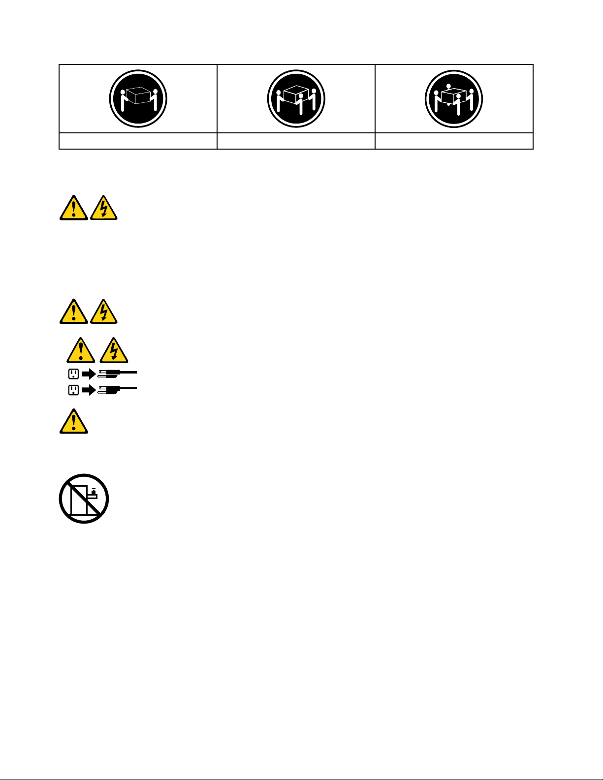
≥18kg(37lbs)≥32kg(70.5lbs)≥55kg(121.2lbs)
1
2
CAUTION:
Usesafepracticeswhenlifting.
CAUTION:
Thepowercontrolbuttononthedeviceandthepowerswitchonthepowersupplydonotturnoff
theelectricalcurrentsuppliedtothedevice.Thedevicealsomighthavemorethanonepower
cord.Toremoveallelectricalcurrentfromthedevice,ensurethatallpowercordsaredisconnected
fromthepowersource.
CAUTION:
Donotplaceanyobjectweighingmorethan82kg(180lbs.)ontopofrack-mounteddevices.
8IdeaCentreA720HardwareMaintenanceManual
Page 15

Chapter3.Generalinformation
Thischapterprovidesgeneralinformationthatappliestoallcomputermodelscoveredbythismanual.
Specications
Thissectionliststhephysicalspecicationsforyourcomputer.
Thissectionliststhephysicalspecicationsforyourcomputer.
TypeIdeaCentreA720
Thissectionliststhephysicalspecications.
Environment
Airtemperature:
Operating:10°to35°C
Transit:-20°to55°C
Humidity:
Operating:35%to80%
Transit:20%to90%(40°C)
Altitude:86KPato106KPa
Electricalinput:
Inputvoltage:90V-264V(AC)
Inputfrequency:47Hz-63Hz
©CopyrightLenovo2012
9
Page 16

10IdeaCentreA720HardwareMaintenanceManual
Page 17

Chapter4.GeneralCheckout
Attention:Thedrivesinthecomputeryouareservicingmighthavebeenrearrangedorthedrivestartup
sequencemayhavebeenchanged.Beextremelycarefulduringwriteoperationssuchascopying,saving,or
formatting.Dataorprogramscanbeoverwrittenifyouselectanincorrectdrive.
Generalerrormessagesappearifaproblemorconictisfoundbyanapplication,theoperatingsystem,or
both.Foranexplanationofthesemessages,refertotheinformationsuppliedwiththatsoftwarepackage.
Usethefollowingproceduretohelpdeterminethecauseoftheproblem:
1.Power-offthecomputerandallexternaldevices.
2.Checkallcablesandpowercords.
3.Setalldisplaycontrolstothemiddleposition.
4.Power-onallexternaldevices.
5.Power-onthecomputer.
•Lookfordisplayederrorcodes.
•Lookforreadableinstructionsoramainmenuonthedisplay.
Ifyoudidnotreceivethecorrectresponse,proceedtostep6.
Ifyoudidreceivethecorrectresponse,proceedtostep7.
6.Ifoneofthefollowinghappens,followtheinstructiongiven:
•IfthecomputerdisplaysaPOSTerror,goto“POSTerrorcodes”.
•Ifthecomputerhangsandnoerrorisdisplayed,continueatstep7.
7.Iftheteststopsandyoucannotcontinue,replacethelastdevicetested.
©CopyrightLenovo2012
11
Page 18

12IdeaCentreA720HardwareMaintenanceManual
Page 19

Chapter5.UsingtheSetupUtility
TheSetupUtilityprogramisusedtoviewandchangethecongurationsettingsofyourcomputer,regardless
ofwhichoperatingsystemyouareusing.However,theoperatingsystemsettingsmightoverrideanysimilar
settingsintheSetupUtilityprogram.
StartingtheLenovoBIOSSetupUtilityprogram
TostarttheLenovoBIOSSetupUtilityprogram,dothefollowing:
1.Ifyourcomputerisalreadyonwhenyoustartthisprocedure,shutdowntheoperatingsystemand
turnoffthecomputer.
2.PressandholdtheF1keythenturnonthecomputer.WhentheLenovoBIOSSetupUtilityprogramis
displayed,releasetheF1key.
Note:IfaPower-OnPasswordoranAdministratorPasswordhasbeenset,theSetupUtilityprogrammenu
willnotbedisplayeduntilyoutypeyourpassword.Formoreinformation,see“Usingpasswords.”
Viewingandchangingsettings
SystemcongurationoptionsarelistedintheLenovoBIOSSetupUtilityprogrammenu.Tovieworchange
settings,see“StartingtheSetupUtilityprogram. ”
YoumustusethekeyboardwhenusingtheLenovoBIOSSetupUtilitymenu.Thekeysusedtoperform
varioustasksaredisplayedonthebottomofeachscreen.
Usingpasswords
YoucanusetheLenovoBIOSSetupUtilityprogramtosetpasswordstopreventunauthorizedpersons
fromgainingaccesstoyourcomputeranddata.See“StartingtheSetupUtilityprogram.”Thefollowing
typesofpasswordsareavailable:
•AdministratorPassword
•Power-OnPassword
Youdonothavetosetanypasswordstouseyourcomputer.However,ifyoudecidetosetpasswords,read
thefollowingsections.
Passwordconsiderations
Apasswordcanbeanycombinationoflettersandnumbersupto16characters(a-zand0-9).Forsecurity
reasons,itisagoodideatouseastrongpasswordthatcannotbeeasilycompromised.Wesuggestthat
passwordsshouldfollowtheserules:
•Forastrongpassword,use7-16charactersandamixoflettersandnumbers.
•Donotuseyournameoryourusername.
•Donotuseacommonwordoracommonname.
•Usesomethingsignicantlydifferentfromyourpreviouspassword.
Attention:AdministratorandPower-Onpasswordsarenotcasesensitive.
©CopyrightLenovo2012
13
Page 20

AdministratorPassword
SettinganAdministratorPassworddetersunauthorizedpersonsfromchangingcongurationsettings.You
mightwanttosetanAdministratorPasswordifyouareresponsibleformaintainingthesettingsofseveral
computers.
AfteryousetanAdministratorPassword,apasswordpromptisdisplayedeverytimeyouaccesstheLenovo
BIOSSetupUtilityprogram.
IfboththeAdministratorandPower-OnPasswordareset,youcantypeeitherpassword.However,youmust
useyourAdministratorPasswordtochangeanycongurationsettings.
Setting,changing,ordeletinganAdministratorpassword
TosetanAdministratorPassword,dothefollowing:
Note:Apasswordcanbeanycombinationoflettersandnumbersupto16characters(a-zand0-9).For
moreinformation,see“Passwordconsiderations”onpage13.
1.StarttheLenovoBIOSSetupUtilityprogram(see“StartingtheLenovoBIOSSetupUtilityprogram”on
page13).
2.FromtheSecuritymenu,selectSetAdministratorPasswordandpresstheEnterkey.
3.Thepassworddialogboxwillbedisplayed.T ypethepasswordthenpresstheEnterkey.
4.Re-typethepasswordtoconrm,thenpresstheEnterkey.Ifyoutypedthepasswordcorrectly,
thepasswordwillbeinstalled.
TochangeanAdministratorPassword,dothefollowing:
1.StarttheLenovoBIOSSetupUtilityprogram(see“StartingtheLenovoBIOSSetupUtilityprogram”on
page13).
2.FromtheSecuritymenu,selectSetAdministratorPasswordandpresstheEnterkey.
3.Thepassworddialogboxwillbedisplayed.TypethecurrentpasswordthenpresstheEnterkey.
4.T ypethenewpassword,thenpresstheEnterkey.Re-typethepasswordtoconrmthenewpassword.
Ifyoutypedthenewpasswordcorrectly,thenewpasswordwillbeinstalled.ASetupNoticedconrming
thatchangeshavebeensavedwillbedisplayed.
TodeleteapreviouslysetAdministratorPassword,dothefollowing:
1.FromtheSecuritymenu,selectSetAdministratorPasswordandpresstheEnterkey.
2.Thepassworddialogboxwillbedisplayed.TypethecurrentpasswordandpresstheEnterkey.
3.T odeleteanAdministratorPassword,leaveeachnewpasswordlineitemblank,thenpresstheEnter
key.ASetupNoticeconrmingthatchangeshavebeensavedwillbedisplayed.
4.ReturntotheLenovoBIOSSetupUtilityprogrammenuandselecttheExitoption.
5.SelectSavechangesandExitfromthemenu.
Power-OnPassword
WhenaPower-OnPasswordisset,youcannotstarttheLenovoBIOSSetupUtilityprogramuntilavalid
passwordistypedfromthekeyboard.
Setting,changing,ordeletingaPower-OnPassword
Note:Apasswordcanbeanycombinationoflettersandnumbersupto16characters(a-zand0-9).
14IdeaCentreA720HardwareMaintenanceManual
Page 21

TosetaPower-OnPassword,dothefollowing:
1.StarttheLenovoBIOSSetupUtilityprogram(See”StartingtheLenovoBIOSSetupUtilityprogram”on
page13.)
2.FromtheSecuritymenu,selectSetPower-OnPasswordandpresstheEnterkey.
3.Thepassworddialogboxwillbedisplayed.T ypethepassword,thenpresstheEnterkey.
4.Re-typethepasswordtoconrm.Ifyoutypedthepasswordcorrectly,thepasswordwillbeinstalled.
TochangeaPower-OnPassword,dothefollowing:
1.StarttheLenovoBIOSSetupUtilityprogram(See”StartingtheLenovoBIOSSetupUtilityprogram”on
page13.)
2.FromtheSecuritymenu,selectSetPower-OnPasswordandpresstheEnterkey.
3.Thepassworddialogboxwillbedisplayed.TypethecurrentpasswordthenpresstheEnterkey.
4.T ypethenewpassword,thenpresstheEnterkey.Re-typethepasswordtoconrmthenewpassword.
Ifyoutypedthenewpasswordcorrectly,thenewpasswordwillbeinstalled.ASetupNoticedconrming
thatchangeshavebeensavedwillbedisplayed.
TodeleteapreviouslysetPower-OnPassword,dothefollowing:
1.FromtheSecuritymenu,selectSetPower-OnPasswordandpresstheEnterkey.
2.Thepassworddialogboxwillbedisplayed.TypethecurrentpasswordandpresstheEnterkey.
3.T odeletethePower-OnPassword,leaveeachnewpasswordlineitemblank,thenpressEnter.ASetup
Noticeconrmingthatchangeshavebeensavedwillbedisplayed.
4.ReturntotheLenovoBIOSSetupUtilityprogrammenuandselecttheExitoption.
5.SelectSavechangesandExitfromthemenu.
Enablingordisablingadevice
TheDevicesoptionsisusedtoenableordisableuseraccesstothefollowingdevices:
USBFunctionsSelectwhethertoenableordisableUSB(UniversalSerial
Bus)functions.Ifthefunctionsaredisabled,noUSB
devicescanbeused.
SATAMode
OnboardAudioControllerSelectwhethertoenableordisabletheOnboard
OnboardEthernetControllerorLANBootAgentSelectwhethertoenableordisabletheOnboardEthernet
Toenableordisableadevice,dothefollowing:
1.StarttheSetupUtilityprogram(see“StartingtheSetupUtilityprogram”onpage13).
2.FromtheSetupUtilityprogrammenu,selectDevices.
3.Selectanoptionasfollows:
WhenthisfeatureissettoDisabled,alldevices
connectedtotheSATAconnectors(e.g.harddiskdrives
ortheopticaldiskdrive)aredisabledandcannotbe
accessed.
AudioController.WhenthisfeatureissettoDisabled
alldevicesconnectedtotheaudioconnectors(e.g.
headphonesoramicrophone)aredisabledandcannot
beused.
Controller,orselectwhethertoenableordisableload
onboardPXE(PrebootExecutionEnvironment).
SelectUSBSetup,presstheEnterkey,thenselectUSBFunctions.
Chapter5.UsingtheSetupUtility15
Page 22

SelectA T ADeviceSetup,presstheEnterkey,thenselectSATAMode.
SelectAudioSetup,presstheEnterkey,thenselectOnboardAudioController.
SelectNetworkSetup,presstheEnterkey,thenselectOnboardEthernetSupportorLANBoot
Agent.
4.SelectDisabledorEnabledandpresstheEnterkey.
5.ReturntotheLenovoBIOSSetupUtilityprogrammenuandselecttheExitoption.
6.SelectSavechangesandExitfromthemenu.
Notes:
a.Ifyoudonotwanttosavethesettings,selectDiscardchangesandExitfromthemenu.
b.SelectIDE/AHCIMode:DevicedriversupportisrequiredforACHI.Dependingonhowtheharddisk
imagewasinstalled,changingthissettingmaypreventthesystemfrombooting.
Selectingastartupdevice
IfyourcomputerdoesnotbootfromadevicesuchastheCD/DVD-ROMdrivediskorharddiskasexpected,
followoneoftheproceduresbelow.
Selectingatemporarystartupdevice
Usethisproceduretostartupfromanybootdevice.
Note:NotallCDs,DVDsorharddiskdrivesarebootable.
1.T urnoffyourcomputer.
2.PressandholdtheF12keythenturnonthecomputer.WhentheStartupDeviceMenuappears,
releasetheF12key.
Note:IftheStartupDeviceMenudoesnotdisplayusingthesesteps,repeatedlypressandreleasethe
F12keyratherthankeepingitpressedwhenturningonthecomputer.
3.Use↑and↓arrowstoselectthedesiredstartupdevicefromtheStartupDeviceMenuandpress
theEnterkeytobegin.
Note:SelectingastartupdevicefromtheStartupDeviceMenudoesnotpermanentlychangethe
startupsequence.
Selectingorchangingthestartupdevicesequence
Tovieworpermanentlychangetheconguredstartupdevicesequence,dothefollowing:
1.StarttheLenovoBIOSSetupUtilityprogram(see“StartingtheLenovoBIOSSetupUtilityprogram”on
page13).
2.FromtheLenovoBIOSSetupUtilityprogrammainmenu,selecttheStartupoption.
3.PresstheEnterkey,andselectthedevicesforthePrimaryBootSequence.Readtheinformation
displayedontherightsideofthescreen.
4.Use↑and↓arrowstoselectadevice.Usethe<+>or<->keystomoveadeviceupordown.Usethe
<×>keytoexcludethedevicefromorincludethedeviceinthebootsequence.
5.ReturntotheLenovoBIOSSetupUtilityprogrammenuandselecttheExitoption.
6.SelectSavechangesandExitfromthemenu.
Notes:
16IdeaCentreA720HardwareMaintenanceManual
Page 23

a.Ifyoudonotwanttosavethesettings,selectDiscardchangesandExitfromthemenu.
b.Ifyouhavechangedthesesettingsandwanttoreturntothedefaultsettings,selectLoadOptimal
Defaultsfromthemenu.
ExitingtheLenovoBIOSSetupUtilityprogram
Afteryounishviewingorchangingsettings,presstheEsckeytoreturntotheLenovoBIOSSetupUtility
programmainmenu.Y oumighthavetopresstheEsckeyseveraltimes.Dooneofthefollowing:
•Ifyouwanttosavethenewsettings,selectSavechangesandExitfromthemenu.WhentheSave&
resetwindowshows,selecttheYesbutton,andthenpresstheEnterkeytoexittheLenovoBIOS
SetupUtilityprogram.
•Ifyoudonotwanttosavethesettings,selectDiscardchangesandExitfromthemenu.Whenthe
ResetWithoutSavingwindowshows,selecttheYesbutton,andthenpresstheEnterkeytoexitthe
LenovoBIOSSetupUtilityprogram.
Chapter5.UsingtheSetupUtility17
Page 24

18IdeaCentreA720HardwareMaintenanceManual
Page 25

Chapter6.Symptom-to-FRUIndex
TheSymptom-to-FRUindexlistserrorsymptomsandpossiblecauses.Themostlikelycauseislistedrst.
AlwaysbeginwithChapter4,“GeneralCheckout, ”onpage11.Thisindexcanalsobeusedtohelpyou
decidewhichFRUstohaveavailablewhenservicingacomputer.Ifyouareunabletocorrecttheproblem
usingthisindex,goto“Undeterminedproblems”onpage20.
Notes:
•Ifyouhavebothanerrormessageandanincorrectaudioresponse,diagnosetheerrormessagerst.
•Ifyoucannotrunthediagnostictestsoryougetadiagnosticerrorcodewhenrunningatestbutdid
receiveaPOSTerrormessage,diagnosethePOSTerrormessagerst.
•Ifyoudidnotreceiveanyerrormessagelookforadescriptionofyourerrorsymptomsintherstpartof
thisindex.
Harddiskdrivebooterror
Aharddiskdrivebooterrorcanbecausedbythefollowing.
Error
Thestartupdriveisnotincludedinthebootsequence
conguration.
Nooperatingsystemisinstalledonthebootdrive.Installanoperatingsystemonthebootdrive.
Thebootsectoronthestartupdriveiscorrupted.
Thedriveisdefective.
FRU/Action
Checkthecongurationandensurethestartupdriveis
inthebootsequence.
Thedrivemustbeformatted.Dothefollowing:
1.Attempttobackupthedataonthefailingharddisk
drive.
2.Usetheoperatingsystemtoformattheharddisk
drive.
Replacetheharddiskdrive.
PowerSupplyProblems
Followtheseproceduresifyoususpectthereisapowersupplyproblem.
Check/VerifyFRU/Action
Checkthatthefollowingareproperlyinstalled:
•PowerCord
•On/OffSwitchconnector
•SystemBoardPowerSupplyconnectors
•Microprocessorconnections
Checkthepowercord.PowerCord
Checkthepower-onswitch.Power-onSwitch
Reseatconnectors
©CopyrightLenovo2012
19
Page 26

POSTerrorcodes
Eachtimeyouturnthecomputeron,itperformsaseriesofteststocheckthatthesystemisoperating
correctlyandthatcertainoptionsareset.ThisseriesoftestsiscalledthePower-OnSelf- T est,orPOST.
POSTdoesthefollowing:
•Checkssomebasicmotherboardoperations
•Checksthatthememoryisworkingcorrectly
•Startsvideooperations
•Veriesthatthebootdriveisworking
POSTErrorMessageDescription/Action
Keyboarderror
RebootandSelectproperBootdeviceorInsertBoot
MediainselectedBootdevice
Cannotinitializethekeyboard.Makesurethekeyboard
isproperlyconnectedtothecomputerandthatnokeys
areheldpressedduringPOST .T opurposelycongure
thecomputerwithoutakeyboard,selectKeyboardless
operationinStartupandsettheoptiontoEnabled.The
BIOSthenignoresthemissingkeyboardduringPOST.
TheBIOSwasunabletondasuitablebootdevice.Make
surethebootdriveisproperlyconnectedtothecomputer.
Makesureyouhavebootablemediainthebootdevice.
Undeterminedproblems
1.Power-offthecomputer.
2.Removeordisconnectthefollowingcomponents(ifconnectedorinstalled)oneatatime.
a.Externaldevices(modem,printer,ormouse)
b.Extendedvideomemory
c.ExternalCache
d.ExternalCacheRAM
e.Harddiskdrive
f.Diskdrive
3.Power-onthecomputertore-testthesystem.
4.Repeatsteps1through3untilyoundthefailingdeviceorcomponent.
Ifalldevicesandcomponentshavebeenremovedandtheproblemcontinues,replacethesystemboard.
20IdeaCentreA720HardwareMaintenanceManual
Page 27

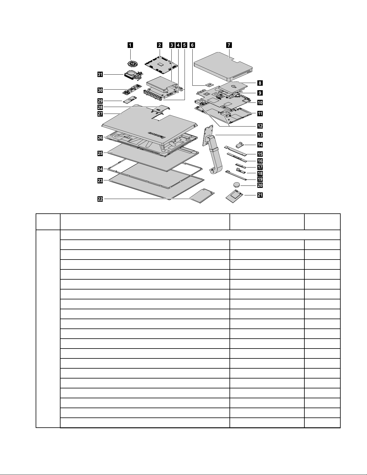
Chapter7.Locatingconnectors,controlsandcomponents
1 2
3 7654 8 9
10 11 12 13 14 15
Thissectionprovidesillustrationstohelplocatethevariousconnectors,controlsandcomponentsofthe
computer.
Fontview
Thefollowingillustrationshowsthelocationofcontrolsandcomponentsonthefrontofthecomputer.
Attention:Becarefulnottoblockanyairventsonthecomputer.Blockedairventscancauseoverheating.
1.Built-inmicrophone
2.Built-incamera
3.Powerindicator11.NovoVisionbutton
4.Harddiskdriveindicator12.Volumedown
5.Bluetoothstatusindicator13.Volumeup
6.WIFIstatusindicator14.Brightnessdown
7.HDMI-inindicator15.Brightnessup
8.Built-inspeakers
©CopyrightLenovo2012
9.MonitorOn/Off
10.PCmode/HDMI-in/AV-inswitch
21
Page 28

Leftandrightview
2 3 4 6 85
9
10
71
Thefollowingillustrationshowsthelocationofconnectors,controlsandcomponentsontheleftandright
sideofthecomputer.
1.Airvents
2.USB3.0connector7.B-CAScardslot(Japanmodelsonly)
3.HDMI-inconnector(selectedmodelsonly)
4.HDMI-outconnector9.Powerbutton
5.Ejectbutton10.Anti-scratchprotector
6.Opticaldrive
8.Memorycardreader
Attention:Donotinsert3-inchdiscsintotheopticaldrive.
22IdeaCentreA720HardwareMaintenanceManual
Page 29

Rearview
1 2
3
8764 5
Thefollowingillustrationshowsthelocationofconnectorsandcomponentsontherearofthecomputer.
1.TVtunerconnector(selectedmodelsonly)5.USB2.0connectors(2)
2.Headphoneconnector6.Powerconnector
3.Microphoneconnector
7.Ethernetconnector(RJ45)
4.USB3.0connector8.Securitycableslot
Chapter7.Locatingconnectors,controlsandcomponents23
Page 30

Hardwarecomponents
4 5 6 7
9
10
11
12
13
14
15
16
17
18
19
20
21
8
23
24
25
26
27
28
29
30
31
22
Thefollowingillustrationshowsthecomponentsthatmakeupyourcomputer.
1.Systemfan
2.Scalarboard
3.Harddiskdrivebracket
17.Bluetoothmodule
18.Powerswitchboard
19.Frontfunctionboard
4.Harddiskdrive20.Battery
5.Harddiskdriverubbers
6.CPU
7.Basecover
8.Opticaldrive
9.Opticaldrivebracket
10.Motherboard
11.Chassis
12.Speakers
13.Hinge29.T ouchcontrolboard
14.Opticaldriveejectboard30.Converter
15.Camera
16.WLANcard
24IdeaCentreA720HardwareMaintenanceManual
21.Solidstatedisk
22.TV-tunercard
23.Glass
24.Panelframe
25.LEDpanel
26.Middleframe
27.Rearcover
28.Rearcoverdeco
31.Heat-sink
Page 31

Identifyingpartsonthemotherboard
Themotherboard(sometimescalledtheplanarorsystemboard)isthemaincircuitboardinyourcomputer.
Itprovidesbasiccomputingfunctionsandsupportsavarietyofdevicesthatarefactory-installedorthat
youcaninstalllater.Thefollowingillustrationshowsthelocationofconnectorsandcomponentsonthe
frontofthemotherboard.
1.HDMI-outconnector
2.HDMI-inconnector
3.USB3.0connector
4.Ethernetconnector(RJ45)
5.Powerconnector
6.Systemfanconnector17.Speakerconnector
7.Scalarcableconnector18.Opticaldriveconnector
8.Scalarcableconnector19.Solidstatediskconnector
9.USB2.0connectors(2)
10.USB3.0connector
11.TVjack1
12.TVjack2(Japanonly)
13.Cardreader
14.Microphoneconnector
15.Headphoneconnector
16.Opticaldriveejectbuttonconnector
20.Harddiskdriveconnector
21.Memoryslot
22.CPUsocket
Chapter7.Locatingconnectors,controlsandcomponents25
Page 32

Thefollowingillustrationshowsthelocationofconnectorsandcomponentsonthebackofthemotherboard.
23.TV-T unercardconnector24.Battery
26IdeaCentreA720HardwareMaintenanceManual
Page 33

IdentifyingpartsonthebackoftheLEDpanel
1 2 3
4
5678
ThefollowingillustrationshowsthecomponentsandcontrolsonthebackofLEDpanel.
1.Bluetoothmodule
2.WLANcard
3.Camera7.Scalarboard
4.T ouchcontrolboard8.Powerswitchboard
5.Frontfunctionboard
6.Converterboard
Chapter7.Locatingconnectors,controlsandcomponents27
Page 34

28IdeaCentreA720HardwareMaintenanceManual
Page 35

Chapter8.Replacinghardware
Attention:Donotremovethecomputercoverorattemptanyrepairbeforereadingthe“Importantsafetyinformation”
intheSafetyandWarrantyGuidethatwasincludedwithyourcomputer.T oobtaincopiesoftheSafetyandWarranty
Guide,gototheSupportWebsiteat:http://consumersupport.lenovo.com.
Note:UseonlypartsprovidedbyLenovo.
Generalinformation
Pre-disassemblyinstructions
Beforestartingthedisassemblyprocedure,makesurethatyoudothefollowing:
1.T urnoffthepowertothesystemandallperipherals.
2.Unplugallpowerandsignalcablesfromthecomputer.
3.Placethesystemonaat,stablesurface.
©CopyrightLenovo2012
29
Page 36

Replacingthekeyboardandmouse
Attention:Turnoffthecomputerandwait3to5minutestoletitcooldownbeforeremovingthecover.
Toreplacethekeyboardandmouse
Step1.Removeanymedia(disks,CDs,DVDsormemorycards)fromthedrives,shutdowntheoperating
system,andturnoffthecomputerandallattacheddevices.
Step2.Unplugallpowercordsfromelectricaloutlets.
Step3.Disconnectallcablesattachedtothecomputer.Thisincludespowercords,input/output(I/O)
cables,andanyothercablesthatareconnectedtothecomputer.Referto“Leftandrightview”
and“Rearview”forhelpwithlocatingthevariousconnectors.
Note:Y ourkeyboardwillbeconnectedtoaUSBconnectorononesideorattherearofthe
computer.
Step4.Disconnectthedefectivekeyboardcablefromthecomputerandconnectthenewkeyboardcable
tothesameconnector.
Note:Themousecanbereplacedusingthesamemethod.
Replacingthepowercordorpoweradapter
Attention:Turnoffthecomputerandwait3to5minutestoletitcooldownbeforeremovingthecover.
Toreplacethepowercordandpoweradapter:
Step1.Removeanymedia(disks,CDs,DVDs,ormemorycards)fromthedrives,shutdowntheoperating
system,andturnoffthecomputerandallattacheddevices.
30IdeaCentreA720HardwareMaintenanceManual
Page 37

Step2.Locatetheconnectorforthepowercord.Referto“Rearview”.
Step3.Disconnectthefailingpowercordandadapterfromthecomputerandconnectthenewpowercord
andadaptertothesameconnector.
Removingthebasecover
Note:Turnoffthecomputerandwait3to5minutestoletitcooldownbeforeremovingthecover.
Note:Itmaybehelpfultoplacethecomputerface-downonasoftatsurfaceforthisprocedure.Lenovo
recommendsthatyouuseablanket,towel,orothersoftclothtoprotectthecomputerscreenfromscratches
orotherdamage.
Toremovethebasecover
Step1.Removeanymedia(disks,CDs,DVDs,ormemorycards)fromthedrives,shutdowntheoperating
system,andturnoffthecomputerandallattacheddevices.
Step2.Unplugallpowercordsfromelectricaloutlets.
Step3.Disconnectallcablesattachedtothecomputer.Thisincludespowercords,input/output(I/O)
cables,andanyothercablesthatareconnectedtothecomputer.Referto“Leftandrightview”
and“Rearview”forhelpwithlocatingthevariousconnectors.
Step4.Placethecomputerface-downonasoftatsurface,thenremovethe7screwsthatsecurethe
basecovertothebase.
Chapter8.Replacinghardware31
Page 38

Step5.Returnthecomputertoanuprightposition,thenliftthebasecoverupandslideitoutasshown.
Step6.Toreattachthebasecover:
a.Lineupthebasecoverwiththebase,slideitbackandsnapitintoposition.
b.Placethecomputerface-downonasoftatsurface,thensecurethebasecovertothebase
withthe7screws.
Replacingtheharddiskdrive
Attention:Turnoffthecomputerandwait3to5minutestoletitcooldownbeforeremovingthecover.
Toreplacetheharddiskdrive
Step1.Removeanymedia(disks,CDs,DVDsormemorycards)fromthedrives,shutdowntheoperating
system,andturnoffthecomputerandallattacheddevices.
Step2.Unplugallpowercordsfromelectricaloutlets.
Step3.Disconnectallcablesattachedtothecomputer.Thisincludespowercords,input/output(I/O)
cables,andanyothercablesthatareconnectedtothecomputer.Referto“Leftandrightview”
and“Rearview”forhelpwithlocatingthevariousconnectors.
Step4.Removethebasecover.Referto“Removingthebasecover”.
32IdeaCentreA720HardwareMaintenanceManual
Page 39
Step5.Removethe2screwsthatsecuretheharddiskdrivetothemotherboard.1
1
1
2
Step6.Disconnectthedataandpowercablefromtheharddiskdrive.2
Step7.Slidetheharddiskdriveandrubberoutofthebayasshown.
Step8.Detachtherubbersfromtheharddiskdriveasshown.
Step9.Installthenewharddiskdriveasfollows:
a.Attachtherubberstothenewharddiskdrive.
b.Lineupthenewharddiskdriveandslideitbackintotheharddiskdrivebay.
Chapter8.Replacinghardware33
Page 40

c.Securethenewharddiskdrivetomotherboardwiththe2screws.
d.Connectthedataandpowercabletothenewharddiskdriveandmotherboard.
Step10.Reattachthebasecoverandsecureitwiththescrews.
Replacingamemorymodule
Attention:Turnoffthecomputerandwait3to5minutestoletitcooldownbeforeremovingthecover.
Toreplaceamemorymodule
Step1.Removeanymedia(disks,CDs,DVDs,ormemorycards)fromthedrives,shutdowntheoperating
system,andturnoffthecomputerandallattacheddevices.
Step2.Unplugallpowercordsfromelectricaloutlets.
Step3.Disconnectallcablesattachedtothecomputer.Thisincludespowercords,input/output(I/O)
cables,andanyothercablesthatareconnectedtothecomputer.Referto“Leftandrightview”
and“Rearview”forhelpwithlocatingthevariousconnectors.
Step4.Removethebasecover.Referto“Removingthebasecover”.
Step5.Pushoutthelatchesonbothsidesofthememorysockettoreleasethememorymodule.Gently
pullthememorymoduleupwardtoremoveitfromitssocket.
Step6.Alignthenewmemorymodulewiththememorysocket,theninsertitandpushdownonthetop
edge.Makesurethelatcheslockthememorymoduleinplace.
Step7.Reattachthebasecoverandsecureitwiththescrews.
Replacingthesystemfan
Note:Turnoffthecomputerandwait3to5minutestoletitcooldownbeforeremovingthecover.
Toreplacethesystemfan
Step1.Removeanymedia(disks,CDs,DVDsormemorycards)fromthedrives,shutdowntheoperating
system,andturnoffthecomputerandallattacheddevices.
Step2.Unplugallpowercordsfromelectricaloutlets.
Step3.Disconnectallcablesattachedtothecomputer.Thisincludespowercords,input/output(I/O)
cables,andanyothercablesthatareconnectedtothecomputer.Referto“Leftandrightview”
and“Rearview”forhelpwithlocatingthevariousconnectors.
Step4.Removethebasecover.Referto“Removingthebasecover”.
34IdeaCentreA720HardwareMaintenanceManual
Page 41

Step5.Removethe3screwsthatsecurethesystemfantotheheat-sink.1
1
2
3
Step6.Disconnectthepowercablefromthemotherboard.2
Step7.Liftthesystemfanuptoremoveit.3
Step8.Lineupthenewsystemfan,thensecureittotheheat-sinkandconnectthenewpowercable
tothemotherboard.
Step9.Reattachthebasecoverandsecureitwiththescrews.
Replacingtheheat-sink
Note:Turnoffthecomputerandwait3to5minutestoletitcooldownbeforeremovingthecover.
Toreplacetheheat-sink:
Step1.Removeanymedia(disks,CDs,DVDsormemorycards)fromthedrives,shutdowntheoperating
system,andturnoffthecomputerandallattacheddevices.
Step2.Unplugallpowercordsfromelectricaloutlets.
Step3.Disconnectallcablesattachedtothecomputer.Thisincludespowercords,input/output(I/O)
cables,andanyothercablesthatareconnectedtothecomputer.Referto“Leftandrightview”
and“Rearview”forhelpwithlocatingthevariousconnectors.
Step4.Removethebasecover.Referto“Removingthebasecover”.
Step5.Removethesystemfan.Referto“Replacingthesystemfan” .
Step6.Removethe9screwsthatsecuretheheat-sinktothemotherboard.
Chapter8.Replacinghardware35
Page 42

Step7.Removetheheat-sinkbyliftingitup.
Attention:Placetheheat-sinkupsidedownonaatsurfacetopreventthermalgreasefromcontaminating
othercomponents.
Attention:Useanalcoholpadtowipethethermalgreaseofftheheat-sinkandCPU.
Step8.Useathermalgreasesyringetoplace5dropsofgreaseonthetopofthemicroprocessor.Each
dropofgreaseshouldbe0.03ml(3tickmarksonthegreasesyringe).
Step9.Lineupthenewheat-sinkthensecureittothemotherboardwiththe9screws.
Step10.Attachthesystemfantothenewheat-sinkandsecureitwiththescrews.
Step11.Reattachthebasecoverandsecureitwiththescrews.
ReplacingtheCPU
Note:Turnoffthecomputerandwait3to5minutestoletitcooldownbeforeremovingthecover.
ToreplacetheCPU
Step1.Removeanymedia(disks,CDs,DVDs,ormemorycards)fromthedrives,shutdowntheoperating
system,andturnoffthecomputerandallattacheddevices.
Step2.Unplugallpowercordsfromelectricaloutlets.
Step3.Disconnectallcablesattachedtothecomputer.Thisincludespowercords,input/output(I/O)
cables,andanyothercablesthatareconnectedtothecomputer.Referto“Leftandrightview”
and“Rearview”forhelpwithlocatingthevariousconnectors.
Step4.Removethebasecover.Referto“Removingthebasecover”.
Step5.Removethesystemfan.Referto“Replacingthesystemfan” .
Step6.Removetheheat-sink.Referto“Replacingtheheat-sink” .
Step7.UseaatheadscrewdrivertoturntheCPUlockscrewcounterclockwisetounlocktheCPU.12
36IdeaCentreA720HardwareMaintenanceManual
Page 43

Step8.Liftthemicroprocessorstraightupandoutofthesocket.3
1 2
3
Attention:Donottouchthegoldcontactsonthebottomofthemicroprocessor.Whenhandlingthe
microprocessor,touchonlythesides.
Note:Donotdropanythingontothemicroprocessorsocketwhileitisexposed.Thesocketpinsmust
bekeptascleanaspossible.
Step9.Holdingthesidesofthemicroprocessorwithyourngers,removetheprotectivecover1that
protectsthegoldcontactsonthenewmicroprocessor.
2
Step10.Holdingthesidesofthemicroprocessorwithyourngers,positionthemicroprocessorsothatthe
notchesonthemicroprocessorarealignedwiththetabsinthemicroprocessorsocket.
Important:Toavoiddamagingthemicroprocessorcontacts,keepthemicroprocessorcompletelylevel
whileinstallingitintothesocket.
Chapter8.Replacinghardware37
Page 44

Step11.Lowerthemicroprocessorstraightdownintoitssocketonthemotherboard.
Step12.T osecurethemicroprocessorinthesocket,closethemicroprocessorretainerandlockitinto
positionwiththesmallhandle.
Step13.Useathermalgreasesyringetoplace5dropsofgreaseonthetopofthemicroprocessor.Each
dropofgreaseshouldbe0.03ml(3tickmarksonthegreasesyringe).
Step14.Reattachthesystemfan,heat-sink,andbasecover,thensecurethemwiththescrews.
Replacingtheopticaldrive
Attention:Turnoffthecomputerandwait3to5minutestoletitcooldownbeforeremovingthecover.
Toreplacetheopticaldrive
Step1.Removeanymedia(disks,CDs,DVDs,ormemorycards)fromthedrives,shutdowntheoperating
system,andturnoffthecomputerandallattacheddevices.
Step2.Unplugallpowercordsfromelectricaloutlets.
Step3.Disconnectallcablesattachedtothecomputer.Thisincludespowercords,input/output(I/O)
cables,andanyothercablesthatareconnectedtothecomputer.Referto“Leftandrightview”
and“Rearview”forhelpwithlocatingthevariousconnectors.
Step4.Removethebasecover.Referto“Removingthebasecover”.
Step5.Disconnecttheopticaldrivedatacablefromthemotherboard.
38IdeaCentreA720HardwareMaintenanceManual
Page 45

Step6.Removethe3screwsthatsecuretheopticaldrivetothemotherboardandliftituptoremoveit.
Step7.Removethe5screwsthatsecuretheopticaldrivetothebracketanddisconnectthedatacable
fromtheopticaldrive.
Step8.Installthenewopticaldriveasfollows:
a.Connectthedatacabletothenewopticaldrive.
b.Alignthenewopticaldrivewiththebracket,pushitintopositionandsecureitwiththe5screws.
c.Lineuptheopticaldrivebracketholeswiththemountingholesinthemotherboardandsecure
itwiththe3screws.
d.Connectthedatacabletothemotherboard.
Step9.Reattachthebasecoverandsecureitwiththescrews.
Chapter8.Replacinghardware39
Page 46

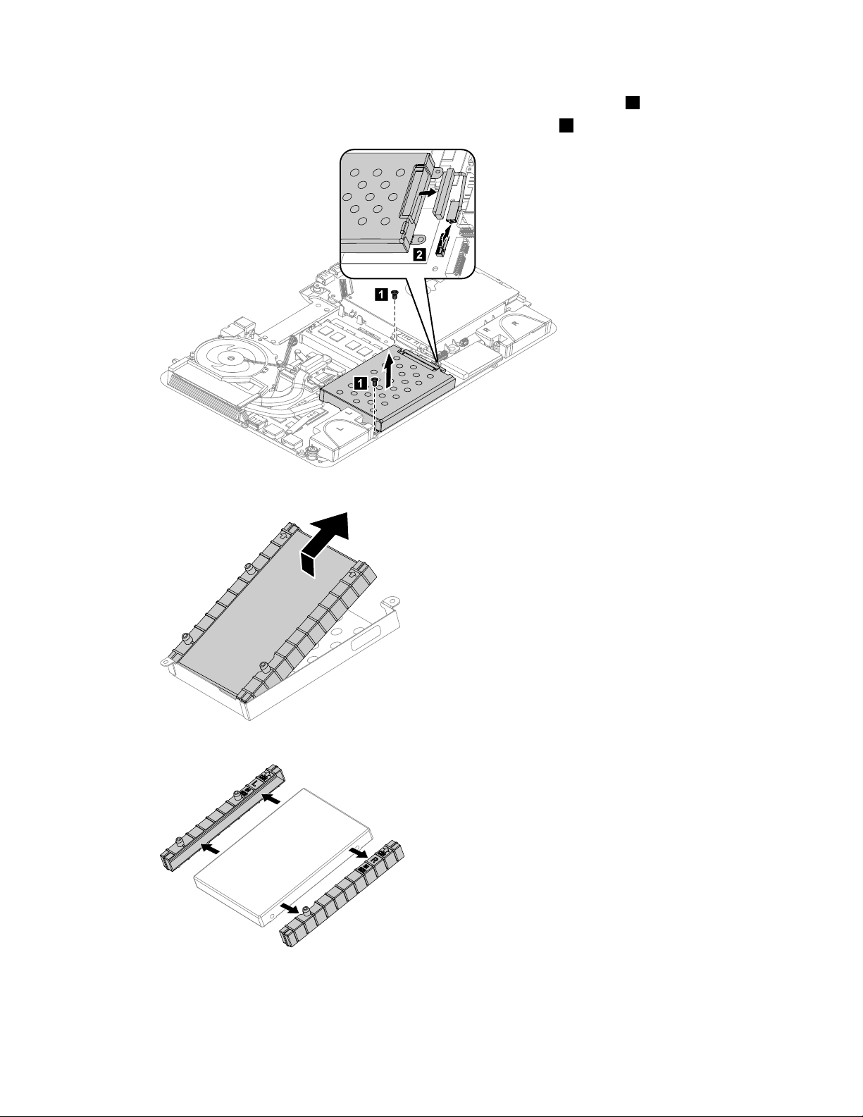
Replacingthesolidstatedisk
Note:Turnoffthecomputerandwait3to5minutestoletitcooldownbeforeremovingthecover.
Toreplacethesolidstatedisk
Step1.Removeanymedia(disks,CDs,DVDs,ormemorycards)fromthedrives,shutdowntheoperating
system,andturnoffthecomputerandallattacheddevices.
Step2.Unplugallpowercordsfromelectricaloutlets.
Step3.Disconnectallcablesattachedtothecomputer.Thisincludespowercords,input/output(I/O)
cables,andanyothercablesthatareconnectedtothecomputer.Referto“Leftandrightview”
and“Rearview”forhelpwithlocatingthevariousconnectors.
Step4.Removethebasecover.Referto“Removingthebasecover”.
Step5.Removethe2screwsthatsecurethesolidstatedisktothemotherboard.
Step6.Pullthesolidstatediskupwardtoremoveitfromthecardport.
Step7.Toinstallthenewsolidstatedisk:
a.Insertthenotchedendofthenewsolidstatediskintothecardportonthemotherboard.
b.Securethenewsolidstatedisktothemotherboardusingthe2screws.
Step8.Reattachthebasecoverandsecureitwiththescrews.
Replacingtheopticaldriveejectboard
Note:Turnoffthecomputerandwait3to5minutestoletitcooldownbeforeremovingthecover.
Toreplacetheopticaldriveejectboard
Step1.Removeanymedia(disks,CDs,DVDs,ormemorycards)fromthedrives,shutdowntheoperating
system,andturnoffthecomputerandallattacheddevices.
Step2.Unplugallpowercordsfromelectricaloutlets.
Step3.Disconnectallcablesattachedtothecomputer.Thisincludespowercords,input/output(I/O)
cables,andanyothercablesthatareconnectedtothecomputer.Referto“Leftandrightview”
and“Rearview”forhelpwithlocatingthevariousconnectors.
Step4.Removethebasecover.Referto“Removingthebasecover”.
Step5.Removethe2screwsthatsecuretheopticaldriveejectboardtothemotherboard.
40IdeaCentreA720HardwareMaintenanceManual
Page 47

Step6.Liftuptheopticaldriveejectboardtoremoveit.
Step7.Toinstallthenewopticaldriveejectboard:
a.Connectthenewopticaldriveejectboardtothemotherboard.
b.Securethenewopticaldriveejectboardtothemotherboardwiththe2screws.
Step8.Reattachthebasecoverandsecureitwiththescrews.
Replacingthemotherboard
Note:Turnoffthecomputerandwait3to5minutestoletitcooldownbeforeremovingthecover.
Toreplacethemotherboard:
Step1.Removeanymedia(disks,CDs,DVDs,ormemorycards)fromthedrives,shutdowntheoperating
system,andturnoffthecomputerandallattacheddevices.
Step2.Unplugallpowercordsfromelectricaloutlets.
Step3.Disconnectallcablesattachedtothecomputer.Thisincludespowercords,input/output(I/O)
cables,andanyothercablesthatareconnectedtothecomputer.Referto“Leftandrightview”
and“Rearview”forhelpwithlocatingthevariousconnectors.
Step4.Removethebasecover.Referto“Removingthebasecover”.
Step5.Removetheharddiskdrive.Referto“Replacingtheharddiskdrive” .
Step6.Removeamemorymodule.Referto“Replacingamemorymodule” .
Step7.Removethesystemfan.Referto“Replacingthesystemfan” .
Step8.Removetheheat-sink.Referto“Replacingtheheat-sink” .
Step9.RemovetheCPU.Referto“ReplacingtheCPU” .
Step10.Removetheopticaldrive.Referto“Replacingtheopticaldrive” .
Step11.Removethesolidstatedisk.Referto“Replacingthesolidstatedisk” .
Step12.Removetheopticaldriveejectboard.Referto“Replacingtheopticaldriveejectboard” .
Step13.Removeallthecablesconnectedtothemotherboard.
Chapter8.Replacinghardware41
Page 48

Step14.Removethe8screwsthatsecurethemotherboardtothechassisandslideitoutasshown.
Step15.Removethe2screwsthatsecuretheTV-Tunercardtothemotherboard.
Step16.Disconnecttheantennacable(s)fromtheTV- T unercard.
Step17.PulltheTV-Tunercardupwardtoremoveitfromthecardport.
42IdeaCentreA720HardwareMaintenanceManual
Page 49

Step18.Useaatheadscrewdriverasalevertopriseoutthebatteryasshown.
Step19.T oinstallthenewmotherboard:
a.Insertthebattery(CR2032)intothesocketwiththesidelabeled“+”facingup,andpress
thebatteryintoplace.
b.InsertthenotchedendoftheTV-Tunercardintothecardportonthenewmotherboardand
secureitwiththe2screws.
c.Connecttheantennacable(s)totheTV-Tunercard.
d.Lineupthenewmotherboardwiththechassisandslideitintoposition.Aligntheholeson
thenewmotherboardwiththemountingholesonthechassisandsecureittothechassis
withthescrews.
e.Attachtheopticaldriveejectboard,solidstatedisk,opticaldrive,CPU,heat-sink,systemfan,
memorymodule,harddiskdrivetothenewmotherboard.
f.Connectallthecablestothenewmotherboard.
Step20.Reattachthebasecoverandsecureitwiththescrews.
Replacingthespeakersystem
Note:Turnoffthecomputerandwait3to5minutestoletitcooldownbeforeremovingthecover.
Toreplacethespeakersystem:
Step1.Removeanymedia(disks,CDs,DVDs,ormemorycards)fromthedrives,shutdowntheoperating
system,andturnoffthecomputerandallattacheddevices.
Step2.Unplugallpowercordsfromelectricaloutlets.
Step3.Disconnectallcablesattachedtothecomputer.Thisincludespowercords,input/output(I/O)
cables,andanyothercablesthatareconnectedtothecomputer.Referto“Leftandrightview”
and“Rearview”forhelpwithlocatingthevariousconnectors.
Step4.Removethebasecover.Referto“Removingthebasecover”.
Step5.Removetheharddiskdrive.Referto“Replacingtheharddiskdrive” .
Step6.Removetheheat-sink.Referto“Replacingtheheat-sink” .
Step7.Removetheopticaldrive.Referto“Replacingtheopticaldrive” .
Step8.Removethehingefromthechassis.Referto“Removingthehingefromthechassis” .
Step9.Disconnectthespeakercablefromtheconnectorsonthemotherboard.
Chapter8.Replacinghardware43
Page 50

Step10.Removethe8screwsthatsecurethemotherboardtothechassisandslideitoutasshown.
Step11.Removethe4screwsthatsecurethespeakersystemtothemotherboard.
Step12.Detachthespeakerfromthechassis.
Step13.T oinstallthenewspeakersystem:
a.Attachthenewspeakercabletothechassis.
b.Lineupthemotherboardwiththechassisandslideitintoposition.Aligntheholesonthe
motherboardwiththemountingholesonthechassisandsecureittothechassiswiththe
8screws.
c.Lineupthenewspeakersystemwiththemotherboardandsecureitwiththe4screws.
d.Connectthenewspeakercabletothemotherboard.
Step14.Reattachtheopticaldrive,heat-sink,andharddiskdrivetothemotherboard.
Step15.Reattachthehingetothechassis,andreconnectthetouchandLEDpanelcablestothe
motherboard.
Step16.Reattachthebasecoverandsecureitwiththescrews.
44IdeaCentreA720HardwareMaintenanceManual
Page 51

ReplacingtheTVtunercard
Note:Turnoffthecomputerandwait3to5minutestoletitcooldownbeforeremovingthecover.
ToreplacetheTVtunercard
Step1.Removeanymedia(disks,CDs,DVDs,ormemorycards)fromthedrives,shutdowntheoperating
system,andturnoffthecomputerandallattacheddevices.
Step2.Unplugallpowercordsfromelectricaloutlets.
Step3.Disconnectallcablesattachedtothecomputer.Thisincludespowercords,input/output(I/O)
cables,andanyothercablesthatareconnectedtothecomputer.Referto“Leftandrightview”
and“Rearview”forhelpwithlocatingthevariousconnectors.
Step4.Removethebasecover.Referto“Removingthebasecover”.
Step5.Removetheharddiskdrive.Referto“Replacingtheharddiskdrive” .
Step6.Removetheheat-sink.Referto“Replacingtheheat-sink” .
Step7.Removetheopticaldrive.Referto“Replacingtheopticaldrive” .
Step8.Removethehingefromthechassis.Referto“Removingthehingefromthechassis” .
Step9.Removeallthecablesconnectedtothemotherboard.
Step10.Removethe8screwsthatsecurethemotherboardtothechassisandslideitoutasshown.
Step11.Removethe2screwsthatsecuretheTV-Tunercardtothemotherboard.
Step12.Disconnecttheantennacable(s)fromtheTV- T unercard.
Chapter8.Replacinghardware45
Page 52

Step13.PulltheTV-Tunercardupwardtoremoveitfromthecardportonthemotherboard.
Step14.T oinstallthenewTV-Tunercard:
a.InsertthenotchedendoftheTV-Tunercardintothecardportonthemotherboard.
b.SecurenewtheTV- T unercardtothemotherboardwiththe2screws.
c.Connecttheantennacable(s)tothenewTV-Tunercard.
Step15.Lineupmotherboardwiththechassisandslideitintoposition.Aligntheholesonthemotherboard
withthemountingholesonthechassisandsecureittothechassiswiththescrews.
Step16.Reattachtheopticaldrive,heat-sink,andharddiskdrivetothemotherboard.
Step17.Reattachthehingetothechassis,andreconnectthetouchandLEDpanelcablestothe
motherboard.
Step18.Reconnectallthecablesbacktothemotherboard.
Step19.Reattachthebasecoverandsecureitwiththescrews.
Replacingthebattery
Note:Turnoffthecomputerandwait3to5minutestoletitcooldownbeforeremovingthecover.
Toreplacethebattery
Step1.Removeanymedia(disks,CDs,DVDs,ormemorycards)fromthedrives,shutdowntheoperating
system,andturnoffthecomputerandallattacheddevices.
Step2.Unplugallpowercordsfromelectricaloutlets.
Step3.Disconnectallcablesattachedtothecomputer.Thisincludespowercords,input/output(I/O)
cables,andanyothercablesthatareconnectedtothecomputer.Referto“Leftandrightview”
and“Rearview”forhelpwithlocatingthevariousconnectors.
Step4.Removethebasecover.Referto“Removingthebasecover”.
Step5.Removetheharddiskdrive.Referto“Replacingtheharddiskdrive” .
Step6.Removetheheat-sink.Referto“Replacingtheheat-sink” .
Step7.Removetheopticaldrive.Referto“Replacingtheopticaldrive” .
Step8.Removethehingefromthechassis.Referto“Removingthehingefromthechassis” .
Step9.Removeallthecablesconnectedtothemotherboard.
46IdeaCentreA720HardwareMaintenanceManual
Page 53

Step10.Removethe8screwsthatsecurethemotherboardtothechassisandslideitoutasshown.
Step11.Useaatheadscrewdriverasalevertopriseoutthebatteryasshown.
Step12.T oinstallthenewbattery:
a.Insertthenewbattery(CR2032)intothesocketwiththesidelabeled“+”facingup,andpress
thebatteryintoplace.
Step13.Lineupthemotherboardwiththechassisandslideitintoposition.Aligntheholesonthe
motherboardwiththemountingholesonthechassisandsecureittothechassiswiththescrews.
Step14.Reattachtheopticaldrive,heat-sink,andharddiskdrivetothemotherboard.
Step15.Reattachthehingetothechassis,andreconnectthetouchandLEDpanelcablestothe
motherboard.
Step16.Reconnectallthecablesbacktothemotherboard.
Step17.Reattachthebasecoverandsecureitwiththescrews.
Removingthehingefromthechassis
Note:Turnoffthecomputerandwait3to5minutestoletitcooldownbeforeremovingthecover.
Toremovethehingefromthechassis
Chapter8.Replacinghardware47
Page 54

Step1.Removeanymedia(disks,CDs,DVDs,ormemorycards)fromthedrives,shutdowntheoperating
1
2
system,andturnoffthecomputerandallattacheddevices.
Step2.Unplugallpowercordsfromelectricaloutlets.
Step3.Disconnectallcablesattachedtothecomputer.Thisincludespowercords,input/output(I/O)
cables,andanyothercablesthatareconnectedtothecomputer.Referto“Leftandrightview”
and“Rearview”forhelpwithlocatingthevariousconnectors.
Step4.Removethebasecover.Referto“Removingthebasecover”.
Step5.DisconnectthetouchandLEDpanelcablesfromtheconnectorsonthemotherboard.
Step6.Removethe6screwsthatsecurethehingetothechassis1,thenraisethehingetoremoveit
fromthechassis.
2
Step7.Toreattachthehingetothechassis:
a.Lineupthehingewiththechassisandslidethehingeintoposition.
b.Securethehingetothechassiswiththe6screws.
c.ReconnectthetouchandLEDpanelcablestothemotherboard.
48IdeaCentreA720HardwareMaintenanceManual
Page 55

Step8.Reattachthebasecoverandsecureitwiththescrews.
1
2
Removingtherearcover
Note:Turnoffthecomputerandwait3to5minutestoletitcooldownbeforeremovingthecover.
Toremovetherearcover
Step1.Removeanymedia(disks,CDs,DVDs,ormemorycards)fromthedrives,shutdowntheoperating
system,andturnoffthecomputerandallattacheddevices.
Step2.Unplugallpowercordsfromelectricaloutlets.
Step3.Disconnectallcablesattachedtothecomputer.Thisincludespowercords,input/output(I/O)
cables,andanyothercablesthatareconnectedtothecomputer.Referto“Leftandrightview”
and“Rearview”forhelpwithlocatingthevariousconnectors.
Step4.Removethebasecover.Referto“Removingthebasecover”.
Step5.Removethehingefromthechassis.Referto“Removingthehingefromthechassis” .
Step6.Raisethehinge1andslidethereardecooutasshown.2
Chapter8.Replacinghardware49
Page 56

Step7.Puttheheadofaatheadscrewdriverbetweenthemiddleframeandtherearcoverasshown.
Fulcru m
Leve r
1
2
Thenusingthescrewdriverasaleverandthemiddleframemetalbarasthefulcrum,prisetherear
coverawayfromthemiddleframe.1
Step8.Workingaroundtheedgeinananti-clockwisedirection,useyourngerstopriseuptherearcover.
Therearcoverispinnedintoplace,useshort,sharpmovementstopriseitup.2
Step9.Pressdownthehingeandslideouttherearcover.
Step10.T oreattachtherearcover:
a.Raisethehinge,lineuptherearcoverwiththeLEDpanelandslideitbackintoposition.
b.PresstheedgeofrearcovertolockthecovertotheLEDpanelwiththepins.
c.Slidethereardecobackintoposition.
Step11.Reattachthehingetothechassis,andreconnectthetouchandLEDpanelcablesbacktothe
motherboard.
Step12.Reattachthebasecoverandsecureitwiththescrews.
Replacingthescalarboard
Note:Turnoffthecomputerandwait3to5minutestoletitcooldownbeforeremovingthecover.
Toreplacethescalarboard
Step1.Removeanymedia(disks,CDs,DVDs,ormemorycards)fromthedrives,shutdowntheoperating
system,andturnoffthecomputerandallattacheddevices.
Step2.Unplugallpowercordsfromelectricaloutlets.
Step3.Disconnectallcablesattachedtothecomputer.Thisincludespowercords,input/output(I/O)
cables,andanyothercablesthatareconnectedtothecomputer.Referto“Leftandrightview”
and“Rearview”forhelpwithlocatingthevariousconnectors.
Step4.Removethebasecover.Referto“Removingthebasecover”.
Step5.Removethehingefromthechassis.Referto“Removingthehingefromthechassis” .
Step6.Removetherearcover.Referto“Removingtherearcover” .
Step7.Removethe3screwsthatsecurethescalarshieldingtothemiddleframe.
50IdeaCentreA720HardwareMaintenanceManual
Page 57

Step8.Removethescalarshieldingandsetitaside.
WLAN
Ca mera
Con verte r
Touch co ntrol
Sc alar
HDMI/DVI
LED/CIR
LVDS
MMB
Po wer
Blue tooth
Step9.Disconnectallthecablesfromthescalarboard.
Step10.Removethe5screwsthatsecurethescalarboardtothemiddleframeandliftituptoremoveit.
Step11.T oinstallthenewscalarboard:
Chapter8.Replacinghardware51
Page 58

a.Lineuptheholesonthenewscalarboardwiththemountingholesonthemiddleframeand
secureitwiththe5screws.
b.Connectallthecablestothenewscalarboard.
c.Reattachthescalarshieldingtothemiddleframewiththe3screws.
Step12.ReattachtherearcovertotheLEDpanel.
Step13.Reattachthehingetothechassis,andreconnectthetouchandLEDpanelcablesbacktothe
motherboard.
Step14.Reattachthebasecoverandsecureitwiththescrews.
Replacingthetouchcontrolboard
Note:Turnoffthecomputerandwait3to5minutestoletitcooldownbeforeremovingthecover.
Toreplacethetouchcontrolboard:
Step1.Removeanymedia(disks,CDs,DVDs,ormemorycards)fromthedrives,shutdowntheoperating
system,andturnoffthecomputerandallattacheddevices.
Step2.Unplugallpowercordsfromelectricaloutlets.
Step3.Disconnectallcablesattachedtothecomputer.Thisincludespowercords,input/output(I/O)
cables,andanyothercablesthatareconnectedtothecomputer.Referto“Leftandrightview”
and“Rearview”forhelpwithlocatingthevariousconnectors.
Step4.Removethebasecover.Referto“Removingthebasecover”.
Step5.Removethehingefromthechassis.Referto“Removingthehingefromthechassis” .
Step6.Removetherearcover.Referto“Removingtherearcover” .
Step7.Disconnectallthetouchcablesfromthetouchcontrolboard.
Step8.Removethe2screwsthatsecurethetouchcontrolboardtothemiddleframe.
Step9.Liftupthetouchcontrolboardtoremoveit.
Step10.T oinstallthenewtouchcontrolboard:
52IdeaCentreA720HardwareMaintenanceManual
Page 59

a.Lineuptheholesonthenewtouchcontrolboardwiththemountingholesonthemiddleframe
1
1
1
1
2
2
andsecureitwiththe2screws.
b.Connectallthecablestothenewtouchcontrolboard.
Step11.ReattachtherearcovertotheLEDpanel.
Step12.Reattachthehingetothechassis,andreconnectthetouchandLEDpanelcablestothe
motherboard.
Step13.Reattachthebasecoverandsecureitwiththescrews.
Replacingtheconverterboard
Note:Turnoffthecomputerandwait3to5minutestoletitcooldownbeforeremovingthecover.
Toreplacetheconverterboard:
Step1.Removeanymedia(disks,CDs,DVDs,ormemorycards)fromthedrives,shutdowntheoperating
system,andturnoffthecomputerandallattacheddevices.
Step2.Unplugallpowercordsfromelectricaloutlets.
Step3.Disconnectallcablesattachedtothecomputer.Thisincludespowercords,input/output(I/O)
cables,andanyothercablesthatareconnectedtothecomputer.Referto“Leftandrightview”
and“Rearview”forhelpwithlocatingthevariousconnectors.
Step4.Removethebasecover.Referto“Removingthebasecover”.
Step5.Removethehingefromthechassis.Referto“Removingthehingefromthechassis” .
Step6.Removetherearcover.Referto“Removingtherearcover” .
Step7.Removethe4screwsthatsecuretheconverterboardtothemiddleframe.1
Step8.Disconnectthe2cablesfromtheconverterboard.2
Step9.Liftuptheconverterboardtoremoveit.
Chapter8.Replacinghardware53
Page 60

Step10.T oinstallthenewconverterboard:
a.Lineuptheholesonthenewconverterboardwiththemountingholesonthemiddleframe
andsecureitwiththe4screws.
b.Connectthe2cablestothenewconverterboard.
Step11.ReattachtherearcovertotheLEDpanel.
Step12.Reattachthehingetothechassis,andreconnectthetouchandLEDpanelcablestothe
motherboard.
Step13.Reattachthebasecoverandsecureitwiththescrews.
Replacingthepowerswitchboard
Note:Turnoffthecomputerandwait3to5minutestoletitcooldownbeforeremovingthecover.
Toreplacethepowerswitchboard
Step1.Removeanymedia(disks,CDs,DVDs,ormemorycards)fromthedrives,shutdowntheoperating
system,andturnoffthecomputerandallattacheddevices.
Step2.Unplugallpowercordsfromelectricaloutlets.
Step3.Disconnectallcablesattachedtothecomputer.Thisincludespowercords,input/output(I/O)
cables,andanyothercablesthatareconnectedtothecomputer.Referto“Leftandrightview”
and“Rearview”forhelpwithlocatingthevariousconnectors.
Step4.Removethebasecover.Referto“Removingthebasecover”.
Step5.Removethehingefromthechassis.Referto“Removingthehingefromthechassis” .
Step6.Removetherearcover.Referto“Removingtherearcover” .
Step7.Disconnectthepowercablefromthepowerswitchboard.
54IdeaCentreA720HardwareMaintenanceManual
Page 61

Step8.RemovethescrewthatsecuresthepowerswitchboardtotheLEDpanelandliftupthepower
switchboardtoremoveit.
Step9.Toinstallthepowerswitchboard:
a.LineuptheholeonthenewpowerswitchboardwiththemountingholeontheLEDpaneland
secureitwiththescrew.
b.Connectthepowercabletothenewconverterboard.
Step10.ReattachtherearcovertotheLEDpanel.
Step11.Reattachthehingetothechassis,andreconnectthetouchandLEDpanelcablestothe
motherboard.
Step12.Reattachthebasecoverandsecureitwiththescrews.
ReplacingtheBluetoothmodule
Attention:Turnoffthecomputerandwait3to5minutestoletitcooldownbeforeremovingthecover.
ToreplacetheBluetoothmodule:
Step1.Removeanymedia(disks,CDs,DVDs,ormemorycards)fromthedrives,shutdowntheoperating
system,andturnoffthecomputerandallattacheddevices.
Step2.Unplugallpowercordsfromelectricaloutlets.
Step3.Disconnectallcablesattachedtothecomputer.Thisincludespowercords,input/output(I/O)
cables,andanyothercablesthatareconnectedtothecomputer.Referto“Leftandrightview”
and“Rearview”forhelpwithlocatingthevariousconnectors.
Step4.Removethebasecover.Referto“Removingthebasecover”.
Step5.Removethehingefromthechassis.Referto“Removingthehingefromthechassis” .
Chapter8.Replacinghardware55
Page 62

Step6.Removetherearcover.Referto“Removingtherearcover” .
1
2
3
Step7.UseasmallatheadscrewdrivertoprisetheBluetoothmoduleawayfromthesocket.12
Step8.DisconnectthecablefromtheBluetoothmodule.3
Step9.ToinstallthenewBluetoothmodule:
a.ConnectthecabletothenewBluetoothmodule.
b.LineupthenewBluetoothmodulewiththesocket,snapitintopositionandsecureitwith
thepins.
Step10.ReattachtherearcovertotheLEDpanel.
Step11.Reattachthehingetothechassis,andreconnectthetouchandLEDpanelcablestothe
motherboard.
Step12.Reattachthebasecoverandsecureitwiththescrews.
ReplacingtheWLANcard
Note:Turnoffthecomputerandwait3to5minutestoletitcooldownbeforeremovingthecover.
ToreplacetheWLANcard:
Step1.Removeanymedia(disks,CDs,DVDs,ormemorycards)fromthedrives,shutdowntheoperating
system,andturnoffthecomputerandallattacheddevices.
Step2.Unplugallpowercordsfromelectricaloutlets.
Step3.Disconnectallcablesattachedtothecomputer.Thisincludespowercords,input/output(I/O)
cables,andanyothercablesthatareconnectedtothecomputer.Referto“Leftandrightview”
and“Rearview”forhelpwithlocatingthevariousconnectors.
Step4.Removethebasecover.Referto“Removingthebasecover”.
Step5.Removethehingefromthechassis.Referto“Removingthehingefromthechassis” .
Step6.Removetherearcover.Referto“Removingtherearcover” .
Step7.UseasmallatheadscrewdrivertoprisetheWLANcardawayfromthesocket.12
Step8.Disconnecttheantennacable3anddatacablefromtheWLANcard.4
56IdeaCentreA720HardwareMaintenanceManual
Page 63

Step9.LiftuptheWLANcardtoremoveitfromthesocket.
1
1
1
1
2
4
3
Step10.T oinstallthenewWLANcard:
a.ConnectthedatacabletothenewWLANcard.
b.LineupthenewWLANcardwiththesocket,snapitintopositionandsecureitwiththepins.
c.ConnecttheantennacabletothenewWLANcard.
Step11.ReattachtherearcovertotheLEDpanel.
Step12.Reattachthehingetothechassis,andreconnectthetouchandLEDpanelcablestothe
motherboard.
Step13.Reattachthebasecoverandsecureitwiththescrews.
Replacingthecamera
Note:Turnoffthecomputerandwait3to5minutestoletitcooldownbeforeremovingthecover.
Toreplacethecamera:
Step1.Removeanymedia(disks,CDs,DVDs,ormemorycards)fromthedrives,shutdowntheoperating
system,andturnoffthecomputerandallattacheddevices.
Step2.Unplugallpowercordsfromelectricaloutlets.
Step3.Disconnectallcablesattachedtothecomputer.Thisincludespowercords,input/output(I/O)
cables,andanyothercablesthatareconnectedtothecomputer.Referto“Leftandrightview”
and“Rearview”forhelpwithlocatingthevariousconnectors.
Step4.Removethebasecover.Referto“Removingthebasecover”.
Step5.Removethehingefromthechassis.Referto“Removingthehingefromthechassis” .
Step6.Removetherearcover.Referto“Removingtherearcover” .
Step7.Removethe2screwsthatsecurethecameratothefrontbezel.1
Chapter8.Replacinghardware57
Page 64

Step8.Liftupthecamera2anddisconnectthedatacablefromthecamera.3
1
2
3
1
Step9.Toinstallthenewcamera:
a.Connectthedatacabletothenewcamera.
b.Lineuptheholesinthenewcamerawiththemountingholesonthefrontbezelandsecure
itwiththe2screws.
Step10.ReattachtherearcovertotheLEDpanel.
Step11.Reattachthehingetothechassis,andreconnectthetouchandLEDpanelcablestothe
motherboard.
Step12.Reattachthebasecoverandsecureitwiththescrews.
Replacingthefrontfunctionboard
Note:Turnoffthecomputerandwait3to5minutestoletitcooldownbeforeremovingthecover.
Toreplacethefrontfunctionboard:
Step1.Removeanymedia(disks,CDs,DVDs,ormemorycards)fromthedrives,shutdowntheoperating
system,andturnoffthecomputerandallattacheddevices.
Step2.Unplugallpowercordsfromelectricaloutlets.
Step3.Disconnectallcablesattachedtothecomputer.Thisincludespowercords,input/output(I/O)
cables,andanyothercablesthatareconnectedtothecomputer.Referto“Leftandrightview”
and“Rearview”forhelpwithlocatingthevariousconnectors.
Step4.Removethebasecover.Referto“Removingthebasecover”.
Step5.Removethehingefromthechassis.Referto“Removingthehingefromthechassis” .
Step6.Removetherearcover.Referto“Removingtherearcover” .
Step7.Removethe2screwsthatsecurethefrontfunctionboardtothefrontbezel.1
Step8.Disconnectthedatacablefromthefrontfunctionboard.2
58IdeaCentreA720HardwareMaintenanceManual
Page 65

Step9.Liftupthefrontfunctionboardtoremoveitfromthefrontbezel.3
3
1
2
1
Step10.T oinstallthenewfrontfunctionboard:
a.Connectthedatacabletothenewfrontfunctionboard.
b.Lineuptheholesinthenewfrontfunctionboardwiththemountingholesonthefrontbezel
andsecureitwiththe2screws.
Step11.ReattachtherearcovertotheLEDpanel.
Step12.Reattachthehingetothechassis,andreconnectthetouchandLEDpanelcablestothe
motherboard.
Step13.Reattachthebasecoverandsecureitwiththescrews.
ReplacingtheLEDpanel
Note:Turnoffthecomputerandwait3to5minutestoletitcooldownbeforeremovingthecover.
Note:Itmaybehelpfultoplacethecomputerface-downonasoftatsurfaceforthisprocedure.Lenovo
recommendsthatyouuseablanket,towel,orothersoftclothtoprotectthecomputerscreenfromscratches
orotherdamage.
ToreplacetheLEDpanel:
Step1.Removeanymedia(disks,CDs,DVDs,ormemorycards)fromthedrives,shutdowntheoperating
system,andturnoffthecomputerandallattacheddevices.
Step2.Unplugallpowercordsfromelectricaloutlets.
Step3.Disconnectallcablesattachedtothecomputer.Thisincludespowercords,input/output(I/O)
Step4.Removethebasecover.Referto“Removingthebasecover”.
Step5.Removethehingefromthechassis.Referto“Removingthehingefromthechassis” .
Step6.Removetherearcover.Referto“Removingtherearcover” .
cables,andanyothercablesthatareconnectedtothecomputer.Referto“Leftandrightview”
and“Rearview”forhelpwithlocatingthevariousconnectors.
Chapter8.Replacinghardware59
Page 66

Step7.Removethescalarboard.Referto“Replacingthescalarboard” .
Step8.Removethetouchcontrolboard.Referto“Replacingthetouchcontrolboard” .
Step9.Removetheconverterboard.Referto“Replacingtheconverterboard” .
Step10.Removethepowerswitchboard.Referto“Replacingthepowerswitchboard” .
Step11.RemovetheBluetoothmodule.Referto“ReplacingtheBluetoothmodule”.
Step12.RemovetheWLANcard.Referto“ReplacingtheWLANcard” .
Step13.RemovetheWLANantennacablefromthefrontbezel.
Step14.Removethecamera.Referto“Replacingthecamera”.
Step15.Removethefrontfunctionboard.Referto“Replacingthefrontfunctionboard”.
Step16.Removeallthecablesattachedtothemiddleframeandthefrontbezel.
60IdeaCentreA720HardwareMaintenanceManual
Page 67

Step17.Removethe6screwsthatsecurethehingetothemiddleframeandsetthehingeaside.
Step18.T oinstallthenewtheLEDpanel:
a.Lineuptheholesonthehingewiththemountingholesonthenewmiddleframeandsecureit
with6screws.
b.AttachallthecablestothenewLEDpanelmiddleframeandfrontbezel.
c.AttachtheWLANcard,Bluetoothmodule,powerswitchboard,converterboard,touchcontrol
board,scalarboardandfrontfunctionboardtothenewLEDpanelmiddleframeandconnect
allthecablestothenewLEDpanel.
Step19.ReattachtherearcovertotheLEDpanel.
Step20.Reattachthehingetothechassis,andreconnectthetouchandLEDpanelcablestothe
motherboard.
Step21.Reattachthebasecoverandsecureitwiththescrews.
FRUlists
Thischapterliststheinformationontheeldreplaceableunits(FRUs).
Attention:BesuretoreadandunderstandallthesafetyinformationbeforereplacinganyFRUs.
Notes:FRUsthathavea1or2intheCRUcolumnareCustomerReplaceableUnits(CRUs).
•1–identiespartsthatarefairlysimpletoreplace,requiringfewornotools.
•2–identiespartsthatareslightlymoredifculttoreplace.
•N-identiespartsthatarenottobereplacedbythecustomer.
Chapter8.Replacinghardware61
Page 68
4 5 6 7
9
10
11
12
13
14
15
16
17
18
19
20
21
8
23
24
25
26
27
28
29
30
31
22
Item#FRUs
ServicePartNumber(FRU
CRUID
#)
Motherboard
A7201G_DDR3W/HDINW/TV1MB
A7202G_DDR3W/HDINW/TV1MB
A7201G_DDR3W/HDINW/OTVMB
A7202G_DDR3W/HDINW/OTVMB
A7201G_DDR3W/OHDINW/OTV1MB
A7202G_DDR3W/OHDINW/OTV1MB
IntelPPTC1HM76Chipset
CPU
IntelI3-3110M2.4GL13M2cPGAProcessor
90000165N
90000166N
90000167N
90000168N
90000169N
90000170N
1100364N
102500303N
10
IntelI5-3210M2.5GL13M2cPGAProcessor
62IdeaCentreA720HardwareMaintenanceManual
IntelI5-3320M2.6GL13M2cPGAProcessor
IntelI5-3360M2.8GL13M2cPGAProcessor
IntelI7-3820QM2.7GE16M4cPGAProcessor
IntelI7-3720QM2.6GE16M4cPGAProcessor
IntelI7-3612QM2.1GE16M4cPGAProcessor
IntelI7-3610QM2.3GE16M4cPGAProcessor
IntelSNBI3-2330M2.2G3MJ1PGA
LAN
RealtekRTL8111F73040793N
102500301N
102500299N
102500297N
102500304N
102500306N
102500290N
102500289N
102500017N
Page 69
AudioN
RealtekALC272-VA4
73040715N
Memory
M471B5773DH0-CK0
HMT325S6CFR8C-PB
MT8KTF25664HZ-1G6M1
Elp_RJ2108BDBG-GN-F2GBD3-1600SMEMORY
M471B5273DH0-CK0
HMT351S6CFR8C-PB
Elp_RJ2108BDBG-GN-F4GBD3-1600SMEMORY
MT16KTF51264HZ-1G6M1
1-100226N
1-100227N
1-100228N
1-100425N
1-100230N
1-100231N
1-100426N
1-100232N
Harddiskdrive
SeagateST9500325AS500G9NBHDD
WDWD5000BPVT-24HXZ5400RPM500GHDD9.5mm4ksector
16-004189N
16004846N
WDWD5000BPVT-24A1YT05400PRM9.5mm500HDD16-200089N
4
WDWD7500BPVT-24HXZ5400RPM750GHDD
16-004848N
WDWD7500BPVT-24A1YT05400PRM9.5mm750HDD16200088N
WDWD10JPVT-24A1YT05400PRM9.5mm1THDD16200071N
A720HDDCable
90200731N
A720HDDBracket90200753N
Solidstatedisk
21
SamsungMZMPA064HMDR64GmSATASSD
SamsungPM830
16-005084N
16200109N
Opticaldiskdrive
HLDSCA30NBDCombo-LH(BE)
PLDSDL-4ETS12.7mmSlimSA T ASlotloadBDCombo
8
PLDSDC-6E2SHBDCombo-LH(BE)
SONYOptiarcAD-7800SlotRambo
HLDSGA31NSlimSATASlotDVDRW
A720ODDCable
14
A720ODDEJECTBOARD
9
A720ODDBracket
25-200325N
25008493N
25-200326N
25-203881N
25-009580N
90200732N
90000217N
90200752N
Graphics
N13P-GL-AIO-A1GT630M
1100400N
VRAM
H5TQ1G63DFR-11C
1007418N
10
K4W1G1646G-BC11
K4W2G1646C-HC11
H5TQ2G63DFR-11CDDR32GRAM
K4W2G1646E-HC11DDR32GRAM
1007420N
1007156N
1100323N
1100321N
Chapter8.Replacinghardware63
Page 70

PowerSupply
FSP150-RAB150Wadapter®
LietonPA-1151-11VA150wadapter(R)
Heat-sink
31
16
22
17
15
12
30
A720CoolMasterDIS45WHeatSink
A720A VCDIS45WHeatSink
Systemfan
1
A720DeltaDIS45WF an
A720AVCDIS45WFan
WLANcard
A720WlanCardW/CABLE
A720WlanAnntena90200739N
TV- T unercard
AvermediaH339BBDVB-TMiniTVCard
AvermediaH339BAATSCMiniTVCard
DVB-T,A TSCHybridMC907
YUANM270BMiniTVCard(R)
AverMediaH339ISDB-TMiniTVCard®
DMB-T(HK)Hybrid:MC163M
YUANMC182AAnalogminiTVCard®
A720TVT unnerCableForNTSL
A720TVT unnerCableForPAL
Remotecontrol
PhilipsWin7IR43KeyController(R)
PhilipsWin7IRReveiver(R)
Bluetoothmodule
FcnBCM92070BT2.1EDRFlashDTCard®
USIBCM92070BT2.1EDRFlashDTCard®
A720BluetoothCardCable
Camera
QuantaH264720POV9712CAM
A720WebcamCable
Speakers
A720Speaker(L+R)
Converter
A720Converter
A720ConverterCable
36-0018761
36-0018751
90200583N
90201255N
90200584N
90201256N
90000171N
11200290N
11200291N
11-013387N
11012147N
11012854N
11-011447N
11012280N
90201142N
90201143N
8880106611
8880106621
11200978N
11200979N
90200741N
20200089N
90200740N
90200743N
90000215N
90200737N
64IdeaCentreA720HardwareMaintenanceManual
Page 71

Touchcontrolboard
Mastouch27"PCTtouchpanelwin8
AUOM270HW02V3Ultra-slimMVA-LED
73041906N
18200174N
A720MastouchT ouchModule90400015N
A7203MLCDT ouchModule
29
A720LCDFrontBezel
A720MastouchMainFrameStand
A7203MMainFrameStand
A720TOUCHCable
90400016N
90200748N
90200749N
90200750N
90200733N
Keyboard
LiteonSK-8861(TW)S-SilkKB-Silver(WW)
LiteonSK-8861(TH)S-SilkKB-Silver(WW)
LiteonSK-8861(BE)S-SilkKB-Silver(WW)
LiteonSK-8861(DE)S-SilkKB-Silver(WW)
LiteonSK-8861(GB)S-SilkKB-Silver(WW)
LiteonSK-8861(IL)S-SilkKB-Silver(WW)
LiteonSK-8861(IT)S-SilkKB-Silver(WW)
LiteonSK-8861(IS)S-SilkKB-Silver(WW)
LiteonSK-8861(Nordic)S-SilkKB-Silver(WW)
LiteonSK-8861(NL)S-SilkKB-Silver(WW)
LiteonSK-8861(EN-FR)S-SilkKB-Silver(WW)
LiteonSK-8861(US)S-SilkKB-Silver(WW)
LiteonSK-8861(PT)S-SilkKB-Silver(WW)
LiteonSK-8861(FR)S-SilkKB-Silver(WW)
LiteonSK-8861(ES)S-SilkKB-Silver(WW)
LiteonSK-8861(JP)S-SilkKB-Silver(WW)
LiteonSK-8861(US-IN)S-SilkKB-Silver(WW)
LiteonSK-8861(SA)S-SilkKB-Silver(WW)
LiteonSK-8861(BR)S-SilkKB-Silver(WW)
LiteonSK-8861(CS-SK)S-SilkKB-Silver(WW)
LiteonSK-8861(GR)S-SilkKB-Silver(WW)
LiteonSK-8861(KR)S-SilkKB-Silver(WW)
LiteonSK-8861(LA)S-SilkKB-Silver(WW)
LiteonSK-8861(RU)S-SilkKB-Silver(WW)
LiteonSK-8861(US-EU)S-SilkKB-Silver(WW)
LiteonSK-8861(SL)S-SilkKB-Silver(WW)
LiteonSK-8861(BG)S-SilkKB-Silver(WW)
LiteonSK-8861(HU)S-SilkKB-Silver(WW)
LiteonSK-8861(TR)S-SilkKB-Silver(WW)
LiteonSK-8861(US-MY)S-SilkKB-Silver(WW)
902005392
902005402
902005412
902005422
902005432
902005442
902005452
902005462
902005472
902005482
902005492
902005502
902005512
902005522
902005532
902005542
902005552
902005562
902005572
902005582
902005592
902005602
902005612
902005622
902005632
902005642
902005652
902005662
902005672
902005682
Chapter8.Replacinghardware65
Page 72

LiteonSK-8861(LA-AR)S-SilkKB-Silver(WW)
Mouse
LiteonSM-8861(WW)MouseSilver(WW)
LiteonSM-8861Mouse(MY)Silver(WW)
LiteonSM-8861Mouse(NoBattery)Silver(WW)
LiteonSM-8861(JP)Mouse-Silver(WW)
Powercords
Volex1.0mC5USPowerCable
longwellBlackSingle-end1.0mSAAPowerCable
Volex1.0mC5AustrilianPowerCable
Luxshare1.0mC5AustrilianPowerCable
1.0MC5JPNpowercordwithconverter®
Volex1.0mC5JapanPowerCable
Luxshare1.0mC5JapanPowerCable
GrandsunBlackSingle-end1.0m3wireCCCPowerCable(R)
Luxshare1.0MC5CCCPowerCable
longwellBlackSingle-end1.0mASTAPowerCable
Volex1.0mC5UKPowerCable
longwellBlackSingle-end1.0mVDEPowerCable
Volex1.0mC5EuropePowerCable
Luxshare1.0mC5EuropePowerCable
longwellBlackSingle-end1.0mIndiaPowerCable
LongwellBlackSingle-end1.0mItalyC5PowerCable®
Volex1.0mC5ItalyPowerCable
LongwellBlackSingle-end1.0mBrazilPowerCable®
Volex1.0mC5BrazilPowerCable
LongwellBlackSingle-end1.0mArgentinaC5PowerCable®
Volex1.0mC5USPowerCable
LongwellBlackSingle-end1.0mDenmarkC5PowerCable®
Volex1.0mC5DenmarkPowerCable
LongwellBlackSingle-end1.0mSwitzerlandC5PowerCable®
Volex1.0mC5SwitzerlandPowerCable
LongwellBlackSingle-end1.0mIsraelC5PowerCable®
Volex1.0mC5IsraelPowerCable
LongwellBlackSingle-end1.0mTaiwanC5PowerCable®
Volex1.0mC5TaiwanPowerCable
LongwellBlackSingle-end1.0mKoreaC5PowerCable®
Volex1.0mC5KoreaPowerCable
902005692
902005702
902005712
902005722
902007812
310338581
310353971
310495001
310495201
31038887linecord
+310396553pin2pin
converter
310495061
310495191
310329531
310451471
310353961
310494961
310353321
310494971
310495181
310353951
310391041
310495041
310358281
310495051
310391001
310495071
310391011
310495031
310391031
310495081
310391071
310495021
310388851
310494991
310391061
310494981
1
66IdeaCentreA720HardwareMaintenanceManual
Page 73

LongwellBlackSingle-end1.0mSAC5PowerCable®
Volex1.0mC5SAPowerCable
310391051
310495011
Mechanical
A720BaseCoverW/BCASW/TV2W/HDMI
A720BaseCoverW/OBCASW/OTV2W/HDMI
90200744N
90200745N
7
A720BaseCoverW/OBCASW/OTV2W/OHDMI
A720BaseCoverW/OBCASW/OTVW/HDMI
90200746N
90200747N
18A720PowerBoard90000214N
19A720LEDFunctionBoard90000216N
2
A720ScalarBoard
A720PANELBACKLIGHTCABLE
A720PowerSwitchCable
A720L VDSCable
A720LEDFunctionBoardCable
A720MMBCable
27
A720BackCover
90000218N
90200734N
90200735N
90200736N
90200738N
90200742N
90200751N
28A720RearDeco90200754N
A720ScalarEMIShielding
90201154N
A720BaseBottomAssy90201155N
Chapter8.Replacinghardware67
Page 74

68IdeaCentreA720HardwareMaintenanceManual
Page 75

Chapter9.Generalinformation
Thischapterprovidesgeneralinformationthatappliestoallcomputermodelscoveredbythismanual.
AdditionalServiceInformation
Thischapterprovidesadditionalinformationthattheservicerepresentativemightndhelpful.
Powermanagement
Powermanagementreducesthepowerconsumptionofcertaincomponentsofthecomputersuchasthe
systempowersupply,processor,harddiskdrives,andsomemonitors.
Advancedcongurationandpowerinterface(ACPI)BIOS
AsthiscomputerhasanACPIBIOSsystem,theoperatingsystemisallowedtocontrolthepower
managementfeaturesofthecomputerandthesettingsforAdvancedPowerManagement(APM)BIOSmode
isignored.NotalloperatingsystemssupportACPIBIOSmode.
AutomaticPower-Onfeatures
TheAutomaticPower-OnfeatureswithinthePowerManagementmenuallowyoutoenableanddisable
featuresthatturnonthecomputerautomatically.
•WakeUponAlarm:Y oucanspecifyadateandtimeatwhichthecomputerwillbeturnedonautomatically.
Thiscanbeeitherasingleevent,adailyeventoraweeklyevent.
•WakeUponLAN:ThisfeatureallowsLANadaptercardtowaketheSystem.
©CopyrightLenovo2012
69
 Loading...