

Lenovo 8822, 8823 Hardware Replacement Manual

WORLDWIDE PARTNER
Hardware Replacement Guide
Type 8822 8823

Contents
Overview
Chapter 1 Locations..........................................................2
Locating connectors on the front of the computer ......................... 2
8822 ........................................................................................................... 2
8823 ........................................................................................................... 3
Locating connectors on the rear of the computer .......................... 5
8822 ........................................................................................................... 5
8823 ........................................................................................................... 6
Chapter 2 Replacing hardware .......................................13
Replacing the keyboard ...............................................................13
Replacing the mouse ...................................................................13
Replacing the internal speaker ....................................................14
Completing the parts replacement ...............................................14


1
Hardware Replacement guide
Overview
This guide is intended to be used by customers who are replacing Customer Replaceable Units (CRUs). In this
guide, CRUs will often be referred to as parts.
This guide does not include procedures for all parts.
It is expected that cables, switches, and certain mechanical parts can be replaced by trained service personnel
without the need for step-by-step procedures..
This guide contains procedures for replacing the following parts:
•
Keyboard
•
Mouse
•
speaker
Safety information for replacing CRUs
Do not open your computer or attempt any repair before reading the “Important safety information” in the
《
Safety and Warranty Guide》 that was included with your computer.
Tools required
To r eplace some parts in your computer, you might need a flat-blade or Phillips screwdriver. Additional tools
might be needed for certain parts.
Handling static-sensitive devices
Static electricity, although harmless to you, can seriously damage computer components. When you are replacing
a part, do not open the static-protective package containing the new part until the defective part has been
removed from the computer and you are ready to install the new part. When you handle parts and other
computer components, take these precautions to avoid static-electricity damage:
•
Limit your movement. Movement can cause static-electricity to build up around you.
•
Always handle parts and other computer components carefully. Handle adapters, memory modules, system
boards, and microprocessors by the edges. Never touch any exposed circuitry.
•
Prevent others from touching the parts and other computer components.
•
Before you replace a new part, touch the static-protective package containing the part to a metal expansion-
slot cover or other unpainted metal surface on the computer for at least two seconds. This reduces static
electricity in the package and your body.
•
When possible, remove the new part from the static-protective packaging, and install it directly in the
computer without setting the part down. When this is not possible, place the static-protective package that
the part came in on a smooth, level surface and place the part on it.
•
Do not place the part on the computer cover or other metal surface.
2
Hardware Replacement guide
1
Chapter
Locations
This chapter provides illustrations to help locate the various connectors, controls and components of the
computer.
Locating connectors on the front of the computer
This section shows the various external connectors on the computer to which you can attach external devices.
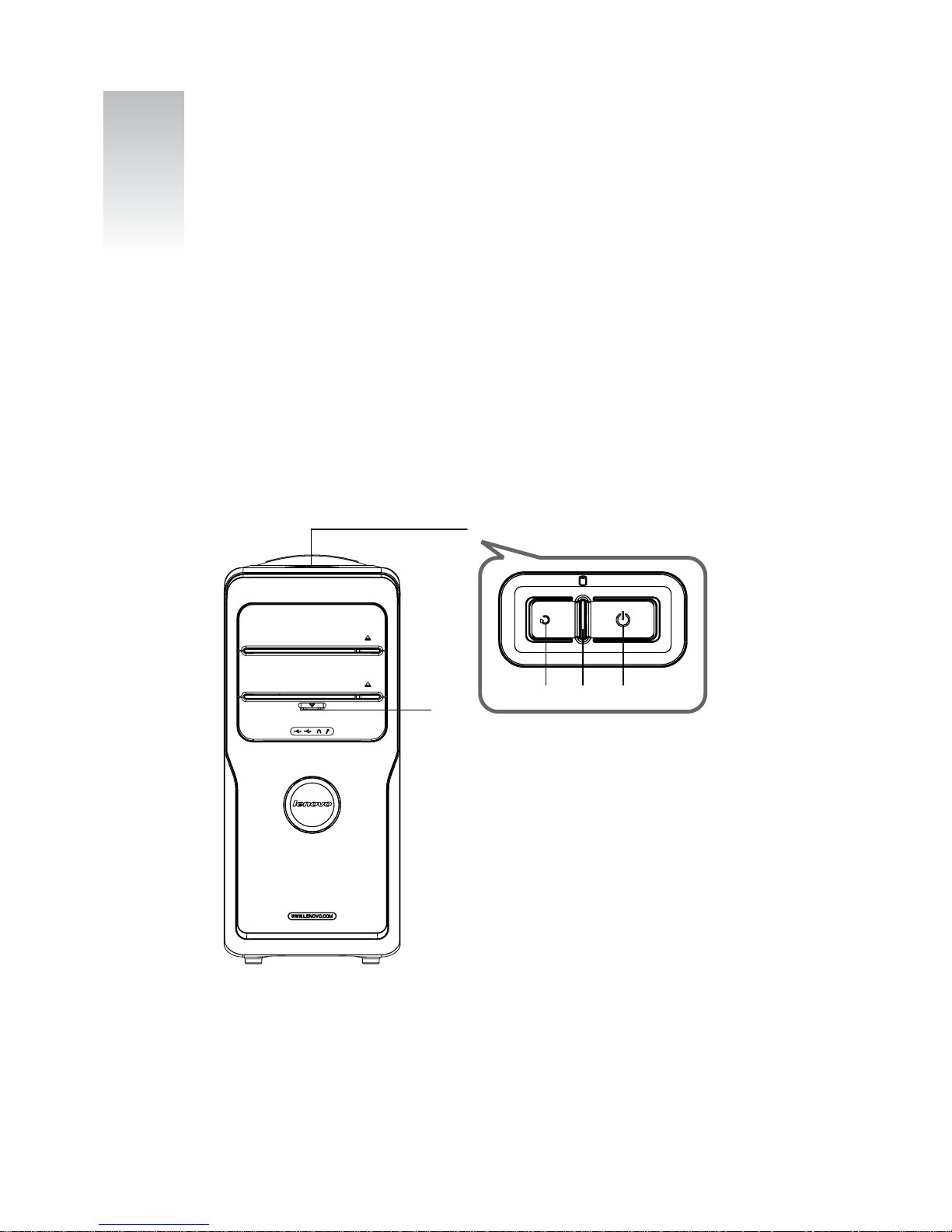
8822
F-1
F-2
[1-1] [1-2] [1-3]
F-1 The top button
[1-1] Reset Key: Press this key to restart computer forcibly. It is recommended to take this operation with
caution.
[1-2] Hard Disk Drive Indicator: Indicates read/write operations of the hard disk.
[1-3] Power Switches: Press this key to turn on/off computers.
3
Hardware Replacement guide
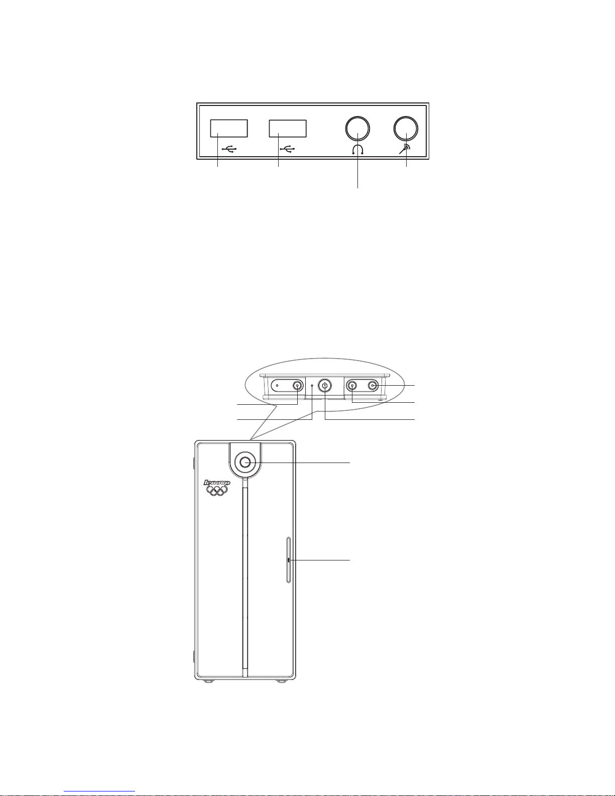
F-2 Preposition Digital Panel: Open the preposition digital panel and the preposition digital connectors
such as USB will be shown as below:
USB
connector
USB
connector
Speaker/
headphone connector
Microphone
connector
D-1 USB Connector: Used to connect USB devices.
D-2 Speaker/Headphone Connector: Used to connect speakers or headphones. If it is necessary to
connect the headphone, remove the speaker plug and insert the headphone plug.
D-3 Microphone Connector: Used to connect the microphone and input the sound received by the microphone
into the computer.
8823
F-1
F-2
F-3
F-4
F-5
F-6
F-7
F-1 Low noise Mode: Press this key to reduce the noise of computers after entering the Windows system.
F-2 Hard Disk Drive Indicator: Indicates read/write operations of the hard disk.
 Loading...