

Lenovo 7893, 8721, 8724 Quick Start Instructions
NOTE: Do not print Pantone Red 032,
it is for print registration only.
Front
!
Flex Enterpise System
1
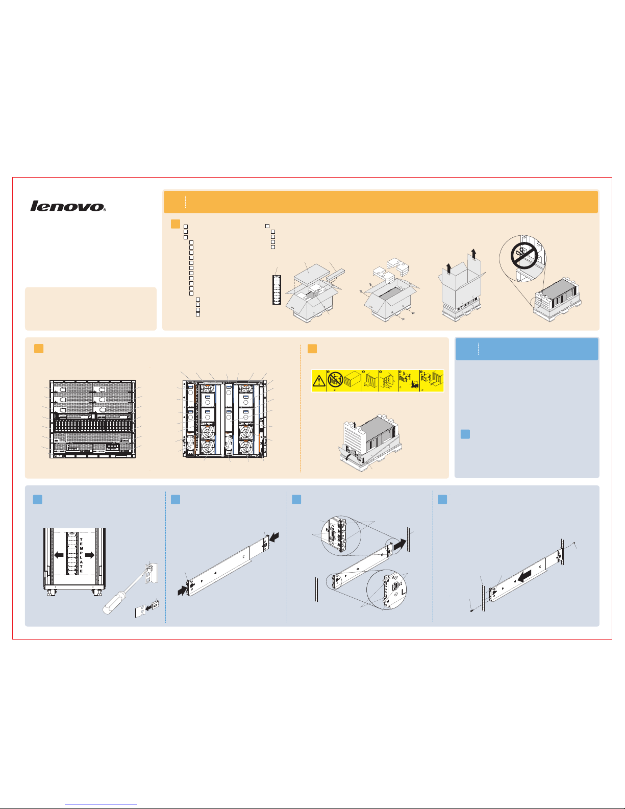
Before you begin
1.1
Lenovo Flex System
Enterprise Chassis
Types 7893, 8721,
and 8724
Quick Start Instructions
Before you install this product, read the safety information in the Lenovo
System Enterprise Chassis Types 7893, 8721, and 8724 Installation and
Service Guide.
Flex
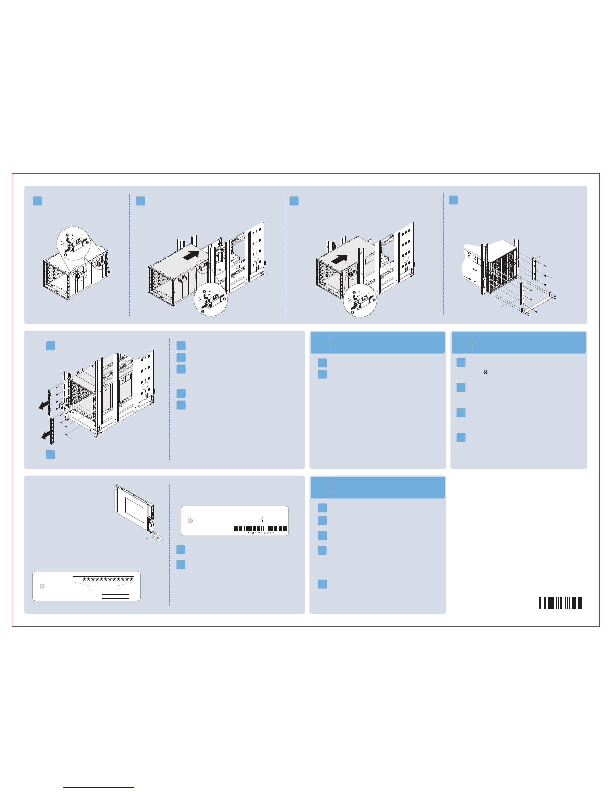
2.2
2.4
2.3
Note:
1. Make sure that the bottom edge of the chassis rail is aligned with the bottom U that
you want the chassis to rest on.
2. If you misalign the chassis rail, press the locking hooks release or squeeze the locking hooks
on the chassis rail, slide the posts out of the holes, and try again.
3. Make sure that the chassis rail posts protrude through the holes
on the front EIA flange.
Note: For detailed instructions, see the Lenovo Flex System Enterprise Chassis
Types 7893, 8721, and 8724 Installation and Service Guide.
2.5
Pull the chassis rail forward and insert the posts on the front of the chassis rail into the
holes on the front EIA flange until it snaps into place. Repeat steps 2.4 and
2.5 for the right chassis rail.
Verify the shipment contents:
1.2
Become familiar with the chassis components. The following modules are standard:
One System Chassis Management Module (CMM), two or more power supplies, six or more fan modules, and two fan logic modules. The chassis might
also include one or more compute nodes, storage nodes, and a management node. The features or modules that you receive might differ from the contents
shown in Figures 1 and 2, depending on what you ordered (see Figures 1 and 2).
Flex
Learn more about the Lenovo Flex System Enterprise Chassis through the
learning modules at
http://pic.dhe.ibm.com/infocenter/flexsys/information/index.jsp.
This site also contains the Flex System product documentation.
Position the left chassis rail in the selected location on the rear of the rack.
Align the posts on the chassis rail with the corresponding holes on the rear EIA
flange. Insert the posts on the rear of the chassis rail through the holes on
the rear EIA flange until the hooks snap into place.
Rear EIA
flange
1.3
66.2 kg
(146 lbs)
220.4 kg (468 lbs)
44.90 kg (99 lbs)
(14X)
(7X)
(6X)
(4X)
(10X)
or
I/
O
To decrease the weight and make the chassis easier to install in a rack, remove
components from the chassis. Make a note of each component location so that
the component can be reinstalled in the same location. Press on the colored
latch and pull on the handles to remove the components. You can also remove
the shelves from the chassis to reduce the weight further.
4. Install an M5 combi-head screw in each end of the rail.
Use the lower threaded hole on the front and the upper
threaded hole on the rear.
Figure 2. Rear view of the Lenovo Flex System Enterprise Chassis
Powersupply
bay 6
Powersupply
bay 5
Powersupply
bay 4
Fan
bay 10
Fan
bay 9
Fan
bay 8
Fan
bay 7
Fan
bay 6
Fan logic
bay 2
I/O bay 1
Power-supply
bay 1
I/O bay 3
Powersupply
bay 3
I/O bay 2
Fan
bay 5
I/O bay 4
CMM
bay 2
Powersupply
bay 2
Fan
bay 4
Fan
bay 3
Fan logic
bay 1
Fan
bay 2
Fan
bay 1
CMM
bay 1
M5 clip nut
Front of rail
Rear of rail
Locking
hooks
release
LEFT FR
ONT
Front EIA
flange
LEFT FR
ONT
Retract both chassis rails, if they are not already retracted.
LEFT FRONT
Figure 1. Front view of the Lenovo System Enterprise ChassisFlex
Bay 1
Bay 5
Bay 3
Bay 7
Bay 11
Bay 9
Bay 13
Bay 2
Bay 6
Bay 4
Bay 8
Bay 12
Bay 10
Bay 14
Information
panel
To access the lower chassis components, loosen the Sanstrap stretch band
on the bottom tray and fold the bottom tray flaps down.
M5 combi-head
screw (black)
Posts
Hooks
Threaded hole
Hooks
Posts
Threaded hole
Note: Do not cut the Sanstrap stretch band on the bottom tray.
10 M5 x 16 combi-head screws (black)
8 M5 x 16 captive-washer screws (silver)
12 M5 clip nuts - 74F1823
12 M5 cage nuts - 81Y2820
1 lower shipping bracket - 81Y2988
1 left shipping bracket - 81Y2986
1 right shipping bracket - 81Y2991
4 chassis lift handles
1 power cable per power supply
1 Sanstrap stretch band
Accessory kit
Rack installation
template
10 hook-and-loop strips - 51H9502
8 M5 x 16
1 left chassis-mounting rail
1 right chassis-mounting rail
combi-head screws (4 extra, black)
Rail installation kit - 88Y6763
Accessory kit Rail installation kit
Flex System chassis
Sanstrap stretch band
M5 cage nut
2
Install the Lenovo
Enterprise Chassis in a rack
Flex System
• You will need at least 10U of available space to install the Lenovo Flex
System Enterprise Chassis.
2.1
Remove the rack door, if one is installed on the rack.
M5 combi-head
screw (black)
Lenovo Flex System Enterprise Chassis
Rack installation template
Enterprise Chassis Documentation CD
Important Notices document
Statement of Limited Warranty
ode labels N
Documentation kit
Align the rack template with the holes in the EIA flange (internal to rack).
For EIA flanges with square holes, install M5 cage nuts from the accessory
kit in the holes that are indicated on the template. If the EIA flanges have
round holes, install the M5 clip nuts from the accessory kit instead of the
M5 cage nuts.
Note: Install cage nuts or clip nuts on the front and back EIA flanges.
• Make sure that there is sufficient room in front of the front EIA flange to
provide minimum bezel clearance of 50 mm (1.97 inches).
•
EIA flanges to 719 mm (28.3 inches) outside to outside.
If you have an adjustable rack, set the distance between the front and rear
2.9
3
Power the Flex System Enterprise Chassis
3.1
3.2
LEDs are on both the front and rear of the chassis. The rear
LEDs are below fan bay 1. Make sure that the following LEDs are lit:
•
The logo on the front information panel
The dc power and ac power LEDs on each power supply
(see Figure 2 in step 1.2)
Power LEDs on each I/O module
(see Figure 2 in step 1.2)
•
•
Connect the applicable power cords and supply power to the
Lenovo Flex System Enterprise Chassis.
Right
support
bracket
Left
support
bracket
Lower
support
bracket
M5 combi-head
screws (black)
2.6
Attach the chassis handles. Align the slots on the
handle with the posts on the side of the chassis
and slide the handle up until it locks into place.
2.7
Lift the chassis up, place the rear of the chassis onto the chassis rails, and slide
the chassis into the rack until the rear chassis handles are near the front rack rails.
While you support THE FRONT OF the chassis, remove each rear handle by pressing
inward on the spring latches on the handle and sliding the handle down.
2.8
Slide the chassis farther into the rack until the front chassis handles are
near the front rack rails, and remove the front handles. Then, slide the chassis all the
way into the rack.
Handle
Handle
Handle
4
Connect to the Chassis Management
Module by direct connection
4.1
4.2
4.3
4.6
2.10
Remove the plastic label plates from both sides of the chassis.
2.11
Insert eight M5 captive-washer screws (silver) into the front of the
chassis to secure it in the rack.
2.12
Reinstall the plastic on both sides of the chassis. label plates
2.13
Reinstall the chassis shelves, if you removed them earlier.
2.14
Reinstall all the components in the chassis.
2.15
(Optional) Install the chassis airborne contaminant filter.
2.16
Cable the I/O modules to the network devices in the data network.
M5 captive-washer
screw (silver)
Next Steps
Connect an Ethernet cable from a client computer to the active Chassis
Management Module (CMM) by a direct connection. If two CMMs are
installed, you only have to configure the primary CMM. The
The primary CMM automatically
synchronizes the configuration with the standby CMM.
Active LED
will be lit ( ) on the primary CMM.
To connect to the CMM for the first time, you might have to change the
Internet Protocol properties on the client computer. Make sure that the
the client computer subnet is the same as the CMM subnet
(the default CMM subnet is 255.255.255.0). The CMM IP address must
also be in the same local domain as the client computer IP address.
Open a web browser on the client computer, and direct it to the CMM IP
address. You must use a secure connection ( ). https://192.168.70.100
4.5
The first time you log in to the CMM, the initial setup wizard opens.
Perform the initial configuration of the CMM.
Network access tag
The network access tag lists the following initial
connection information for the CMM:
• MAC address
• Default host name
• IPv6 Link Local Address (LLA)
• Default IPv4 static IP address (192.168.70.100)
• Default user name (USERID)
• Default password (PASSW0RD, where
the number zero, not the letter O, is used)
Network
access tag
Connect via Static IP
The front of the network access tag lists the CMM MAC address, default
host name, and IPv6 LLA, as shown in the following illustration.
Front
The rear of the network access tag lists the default IPv4 static IP address,
default user name, and default password, as shown in the following illustration.
Rear
5
5.1
5.2
Start the Flex System Manager management node and complete
the initial setup.
If you are setting up a
use a console breakout cable to connect a keyboard, mouse,
and monitor directly to the management node.
Flex System Manager management node,
5.3
Restart the CMM from the CMM user interface. As the CMM is restarting,
connect a cable from the Ethernet port on the CMM to your network.
The network access tag is attached to the front of the CMM.
Initial setup is now complete. You are ready to begin using the
Lenovo Flex System Enterprise Chassis.
4.4
Enter the CMM user name and password to start the remote session.
• The user ID and password are case sensitive. The same user ID and
password are used for all methods of connecting to the CMM.
• The default CMM user name is USERID, and the default password is
PASSW0RD (note the number zero, not the letter O, in PASSW0RD).
You will be required to change the default password when you log
in for the first time.
Note: The manufacturing default static IPv4 IP address is
192.168.70.100, and the default IPv4 subnet address is 255.255.255.0.
5.5
Log in to the user interface of each of the switches in the chassis and
configure them.
If you plan to transport the rack to another location, you
must install the support brackets that come with the chassis.
1. Align the right support bracket with the four slots on the rear
of the chassis (outside of the chassis wall).
2. Slide the support bracket forward until it locks into place in the slots.
3. Secure the support bracket to the rack with three M5 combi-head
screws (black).
4. Repeat steps 1 through 3 for the left support bracket.
5. Fit the lower support bracket to the chassis; then, slide it forward
against the rack rails and secure the bracket with four M5 combi-head
screws (black).
Default Information:
URL:
User Name:
Password:
https://192.168.70.100
USERID
PASSW0RD
ZERO
Secure connection required.
(e.g., SSH, https://, etc.)
MAC Address (Last 12 characters)
Default Hostname:
MM Label Here
DHCP is
enabled
by default
LLA Label Here
IPv6 Link Local Address (LLA):
MM
5.4
After you complete the initial configuration, you can access the Flex
System Manager user interface to complete the setup and begin
managing the chassis.
On a client computer that is connected to your network,
point your browser to , where IP_address
is the IP address that you entered during the initial configuration
(in step 5.3).
https://IP_address
Note: When you reinstall the compute nodes, storage nodes, and
the Flex System Manager management node, be sure to install
from the bottom up (the first node in node bay 1, the second node
in node bay 2, and so on).
The product documentation is available at
http://pic.dhe.ibm.com/infocenter/flexsys/information/index.jsp
If any of the LEDs are not lit, complete the following steps:
1. Remove power from the chassis.
2. Reseat all components in the chassis.
3. Supply power to the chassis. If the problem remains,
contact Support.
P/N 00FE371
Edition 3
For step-by-step instructions for setting up your Lenovo Flex System Enterprise
Chassis and performing common management tasks, go to
http:// ibm.com/infocenter/flexsys/information
/topic/com.ibm.acc.commontasks.doc/commontasks_intro.html
pic.dhe.
03/10/2015
Set the IP address for each of the components in the chassis. This
includes the IP address of the IMM or FSP in each of the compute nodes
and the IP address of each of the switches in the chassis. From the
CMM user interface, select Chassis Management > Component
IP Configuration. Then, select a device to change its IP address.
Notes:
• You must restart each device to show the new IP address.
• Due to the design of the Flex System Chassis, it is important to have all
management network traffic on a separate subnet than the data traffic.
This means all CMMs, IMMs, FSPs, and switch management interfaces
should be on a different subnet/VLAN than the data production traffic of
the other chassis components (such as node operating systems).
Back
NOTE: Do not print Pantone Red 032,
it is for print registration only.
 Loading...