

Lenovo 7515-J9U - ThinkCentre A58 Desktop PC, Thinkcentre 7515, Thinkcentre 7523, Thinkcentre 7569, Thinkcentre 7611 User Manual

ThinkCentre
User Guide
Machine Types: 7515, 7523, 7569, and 7611


ThinkCentre
User Guide

Note
Before using this information and the product it supports, be sure to read and understand the ThinkCentre Safety and
Warranty Guide and “Notices,” on page 77.
Third Edition (October 2009)
© Copyright Lenovo 2009.
LENOVO products, data, computer software, and services have been developed exclusively at private expense and
are sold to governmental entities as commercial items as defined by 48 C.F.R. 2.101 with limited and restricted
rights to use, reproduction and disclosure.
LIMITED AND RESTRICTED RIGHTS NOTICE: If products, data, computer software, or services are delivered
pursuant a General Services Administration ″GSA″ contract, use, reproduction, or disclosure is subject to restrictions
set forth in Contract No. GS-35F-05925.

Contents
Important safety information ......v
Chapter 1. Product overview ......1
Features ................1
Specifications ..............4
Software overview ............5
Software provided with your Windows operating
system ...............5
Locations ...............7
Locating connectors on the front of your computer 7
Locating connectors on the rear of your computer 8
Locating components ..........10
Locating parts on the system board .....11
Chapter 2. Installing options and
replacing hardware .........13
Handling static-sensitive devices .......13
Installing options and replacing hardware ....13
Installing external options ........14
Removing the computer cover .......14
Removing and reinstalling the front bezel . . . 16
Installing internal options ........17
Replacing the power supply assembly....26
Replacing the heat sink and fan assembly . . . 27
Replacing the microprocessor .......29
Replacing the primary hard disk drive ....32
Replacing the secondary hard disk drive . . . 34
Replacing the optical drive ........37
Replacing the diskette drive ........39
Replacing the front fan assembly ......40
Replacing the rear fan assembly ......42
Replacing the keyboard .........45
Replacing the mouse ..........46
Completing the parts replacement ......46
Installing security features .........47
Integrated cable lock ..........48
Padlock...............49
Password protection ..........49
Erasing lost or forgotten passwords (clearing
CMOS) ...............49
Chapter 3. Recovery information . . . 51
Creating and using recovery media ......51
Creating recovery media .........51
Using recovery media ..........52
Performing backup and recovery operations . . . 52
Performing a backup operation .......53
Performing a recovery operation ......53
Using the Rescue and Recovery workspace ....54
Creating and using rescue media .......55
Creating rescue media ..........55
Using rescue media...........55
Creating and using a recovery repair diskette . . . 56
Creating a recovery repair diskette .....56
Using a recovery repair diskette ......56
Installing or reinstalling device drivers .....57
Setting a rescue device in the startup sequence . . 58
Solving recovery problems .........58
Chapter 4. Using the Setup Utility . . . 59
Starting the Setup Utility program.......59
Viewing and changing settings ........59
Using passwords ............59
Password considerations .........60
Power-On Password ..........60
Administrator Password .........60
Setting, changing, and deleting a password . . . 60
Enabling or disabling a device ........61
Selecting a startup device..........61
Selecting a temporary startup device .....61
Selecting or changing the startup device sequence 62
Exiting from the Setup Utility program .....62
Chapter 5. Updating system programs 63
Using system programs ..........63
Updating (flashing) BIOS from a disc ......63
Updating (flashing) BIOS from your operating
system ................64
Recovering from a POST/BIOS update failure . . . 64
Chapter 6. Troubleshooting and
diagnostics .............67
Basic troubleshooting ...........67
Diagnostic programs ...........68
Lenovo ThinkVantage Toolbox .......69
Lenovo System Toolbox .........69
PC-Doctor for Rescue and Recovery .....69
PC-Doctor for DOS ...........70
Cleaning the mouse ...........71
Optical mouse ............71
Non-optical mouse ...........71
Chapter 7. Getting information, help,
and service .............73
Information resources ...........73
Online Books folder ..........73
Lenovo ThinkVantage Tools ........73
Lenovo Care .............73
Lenovo Welcome ...........74
Access Help .............74
Safety and Warranty ..........74
Lenovo Web site (http://www.lenovo.com). . . 74
Help and service ............75
Using the documentation and diagnostic
programs ..............75
Calling for service ...........75
Using other services ..........76
Purchasing additional services .......76
© Copyright Lenovo 2009 iii

Appendix. Notices ..........77
Television output notice ..........78
European conformance CE mark .......78
Trademarks ..............78
Index ...............79
iv
User Guide

Important safety information
CAUTION:
Before using this manual, be sure to read and understand all the related safety
information for this product. Refer to the ThinkCentre Safety and Warranty Guide
that you received with this product for the latest safety information. Reading
and understanding this safety information reduces the risk of personal injury
and or damage to your product.
If you no longer have a copy of the ThinkCentre Safety and Warranty Guide, you can
obtain a Portable Document Format (PDF) version from the Lenovo
®
Support Web
site at:
http://www.lenovo.com/support
© Copyright Lenovo 2009 v

vi User Guide

Chapter 1. Product overview
This chapter describes the computer features, specifications, preinstalled software
programs, and part and connector locations.
Features
This section provides an overview of the computer features.
System information
The following information covers a variety of models. For information about
your specific model, use the Setup Utility program. See Chapter 4, “Using the
Setup Utility,” on page 59.
Microprocessor
v Intel®Celeron®processor
v Intel Celeron dual-core processor
®
v Intel Pentium
v Intel Core™2 Duo processor
v Intel Core 2 Quad processor
v Internal cache (size varies by model type)
dual-core processor
Memory
v Supports up to two double data rate 2 dual inline memory modules (DDR2
DIMMs)
Internal drives
v Diskette drive or card reader (varies by model type)
v Serial Advanced Technology Attachment (SATA) internal hard disk drive
v Optical drive
Video subsystem
v Integrated graphics card for a Video Graphics Array (VGA) connector
v PCI (Peripheral Component Interconnect) Express x16 graphics card slot on the
system board for a discrete graphics card
© Copyright Lenovo 2009 1

Audio subsystem
v Integrated high-definition (HD) audio
v Microphone connector and headphone connector on the front panel
v Audio line-in connector, audio line-out connector, and microphone connector on
the rear panel
v Internal speaker (some models)
Connectivity
v 10/100/1000 Mbps integrated Ethernet controller
v PCI V.90 Data/Fax modem (some models)
System management features
v Ability to store power-on self-test (POST) hardware test results
v Automatic power-on startup
v Preboot Execution Environment (PXE)
v Remote Administration
v System Management (SM) Basic Input/Output System (BIOS) and SM software
v Wake on LAN
v Wake on Ring (in the Setup Utility program, this feature is called Serial Port
Ring Detect for an external modem)
Input/Output (I/O) features
v 9-pin serial port (one standard and one optional)
v Ethernet connector
v One standard 25-pin parallel port
v Six USB connectors (two on the front panel and four on the rear panel)
v Standard mouse connector
v Standard keyboard connector
v Two audio connectors on the front panel (microphone connector and headphone
connector)
v Three audio connectors on the rear panel (audio line-in connector, audio line-out
connector, and microphone connector)
v VGA monitor connector
Expansion
v Two hard disk drive bays (one standard and one optional)
v One drive bay for either a 3.5-inch diskette drive or a card reader
v Two optical drive bays (one standard and one optional)
v Two PCI 32-bit card slots
v One PCI Express x1 card slot
v One PCI Express x16 graphics card slot
Power
v 280-watt power supply with manual voltage-selection switch
v 280-watt auto-sensing power supply
v 320-watt auto-sensing power supply (some models)
v Advanced Configuration and Power Interface (ACPI) support
2 User Guide

Security features
v Computrace
v Cover presence switch (also called intrusion switch) (some models)
v Hard disk drive password
v Power-On Password (POP) and Administrator Password for BIOS access
v Serial and parallel port I/O control
v Startup sequence control
v Startup without diskette drive, keyboard, or mouse
v Support for the addition of an integrated cable lock (Kensington lock)
v Support to enable or disable a device
v Keyboard with fingerprint reader (some models)
v USB switch on/off
Software programs, preinstalled
Your computer might come with preinstalled software programs. If it does, an
operating system, device drivers to support built-in features, and other support
programs are included. For more information, see “Software overview” on page 5.
Operating system, preinstalled
®
v Microsoft
v Microsoft Windows Vista
Windows®7
®
v Microsoft Windows XP Professional
(preinstalled through downgrade rights in Windows 7 Professional, Windows 7
Ultimate, Windows Vista Business, or Windows Vista Ultimate)
Operating systems, certified or tested for compatibility
v Linux
®
1
(varies by model type)
1. The operating systems listed here are being certified or tested for compatibility at the time this publication goes to press.
Additional operating systems might be identified by Lenovo as compatible with your computer following the publication of this
booklet. Corrections and additions to this list are subject to change. To determine if an operating system has been certified or
tested for compatibility, check the Web site of the operating system vendor.
Chapter 1. Product overview
3

Specifications
This section lists the physical specifications for your computer.
Dimensions
Width: 175 mm (6.9 inches)
Height: 412 mm (16.2 inches)
Depth: 442 mm (17.4 inches)
Weight
Maximum configuration as shipped: 11.2 kg (24.7 lbs)
Environment
Air temperature:
Operating: 10° to 35°C (50° to 95°F)
Non-operating: -40° to 60°C (-40° to 140°F) (with package)
Non-operating: -10° to 60°C (14° to 140°F) (without package)
Humidity:
Operating: 10% to 80% (10% per hour, non condensing)
Non-operating: 10% to 90% (10% per hour, non condensing)
Maximum altitude:
Operating: -50 to 10 000 ft (-15.2 to 3 048 m)
Non-operating: -50 to 35 000 ft (-15.2 to 10 668 m)
Electrical input
Input voltage:
Low range:
Minimum: 100 V ac
Maximum: 127 V ac
Input frequency range: 50 to 60 Hz
Voltage-selection switch setting: 115 V ac
High range:
Minimum: 200 V ac
Maximum: 240 V ac
Input frequency range: 50 to 60 Hz
Voltage-selection switch setting: 230 V ac
4 User Guide

Software overview
The computer comes with a preinstalled operating system and several preinstalled
applications.
Software provided with your Windows operating system
This section describes the Windows applications provided with your computer.
Software provided by Lenovo
The following software programs are provided by Lenovo to help you improve
productivity and reduce the cost associated with maintaining your computer.
Software programs provided with your computer might vary depending on your
model type and preinstalled operating system.
Lenovo ThinkVantage Tools: The Lenovo ThinkVantage
you to a host of information sources and provides easy access to various tools to
help you work more easily and securely. For more information, see “Lenovo
ThinkVantage Tools” on page 73.
Note: The Lenovo ThinkVantage Tools program is only available on computers
Lenovo Care: The Lenovo Care
and tools to help you set up, understand, maintain, and enhance your computer.
For more information, see “Lenovo Care” on page 73.
preinstalled with Windows 7 from Lenovo.
SM
program guides you to a host of information
®
Tools program guides
Note: The Lenovo Care program is only available on computers preinstalled with
Windows Vista or Windows XP from Lenovo.
Lenovo Welcome: The Lenovo Welcome program introduces some innovative
built-in features of Lenovo to you and guides you through some important setup
tasks to help you make the most of your computer.
Note: The Lenovo Welcome program is only available on computers preinstalled
with Windows 7 or Windows Vista from Lenovo.
Product Recovery: The Product Recovery program enables you to restore the
contents of the hard disk drive to the factory default settings.
ThinkVantage Rescue and Recovery: The ThinkVantage Rescue and Recovery
®
(RnR) program is a one button recovery and restore solution that includes a set of
self-recovery tools to help you diagnose computer problems, get help, and recover
from system crashes quickly, even if the primary operating system could not start.
Password Manager: The Password Manager program helps you automatically
capture and fill in authentication information for Windows applications and Web
sites.
ThinkVantage System Update: The ThinkVantage System Update (TVSU)
program helps you keep the software on your system up-to-date by downloading
and installing software packages (TVT applications, device drivers, BIOS flashes,
and other third party applications). Some examples of software that you should
keep updated are programs provided by Lenovo, such as the ThinkVantage Rescue
and Recovery program and the Lenovo Care program.
Chapter 1. Product overview 5

ThinkVantage Power Manager: The ThinkVantage Power Manager program
provides convenient, flexible, and complete power management for your
ThinkCentre
can adjust your power settings to achieve the best balance between system
performance and power saving.
Fingerprint software: The integrated fingerprint reader provided on some
keyboards enables you to enroll your fingerprint and associate it with your
power-on password, hard disk drive password, and Windows password. As a
result, fingerprint authentication can replace passwords and enable simple and
secure user access. A fingerprint reader keyboard is available with select computers
or can be purchased for computers that support this option.
®
computer. By using the ThinkVantage Power Manager program, you
Lenovo ThinkVantage Toolbox
The Lenovo ThinkVantage Toolbox program helps you maintain your computer,
improve computing security, diagnose computer problems, get familiar with the
innovative technologies provided by Lenovo, and get more information about your
computer. See “Lenovo ThinkVantage Toolbox” on page 69 for detailed
information.
Note: The Lenovo ThinkVantage Toolbox program is only available on computers
preinstalled with Windows 7 from Lenovo.
Lenovo System Toolbox
The Lenovo System Toolbox diagnostic program is preinstalled on your hard disk
drive. This diagnostic program works through the Windows operating system to
diagnose hardware problems and report operating-system-controlled settings that
can cause hardware failures. See “Lenovo System Toolbox” on page 69 for more
information.
Note: The Lenovo System Toolbox program is only available on computers
preinstalled with Windows Vista or Windows XP from Lenovo.
PC-Doctor for Rescue and Recovery
The PC-Doctor for Rescue and Recovery diagnostic program is preinstalled on
your hard disk drive. It is part of the Rescue and Recovery workspace on each
Lenovo computer to diagnose hardware problems and report operating-systemcontrolled settings that can cause hardware failures. Use the PC-Doctor for Rescue
and Recovery if you are unable to start the Windows operating system. See
“PC-Doctor for Rescue and Recovery” on page 69 for more information.
Adobe Reader
The Adobe Reader is a tool used to view, print, and search PDF documents.
See “Online Books folder” on page 73 for more information about accessing the
online books and the Lenovo Web site.
Antivirus software
Your computer comes with antivirus software that you can use to detect and
eliminate viruses. Lenovo provides a full version of antivirus software on your
hard disk drive with a free 30-day subscription. After 30 days, you must renew the
license to continue receiving the antivirus program updates.
For more information about updating your antivirus software, refer to the Access
Help. See “Access Help” on page 74 for instructions on how to open the help
system.
6 User Guide
Locations
Locating connectors on the front of your computer
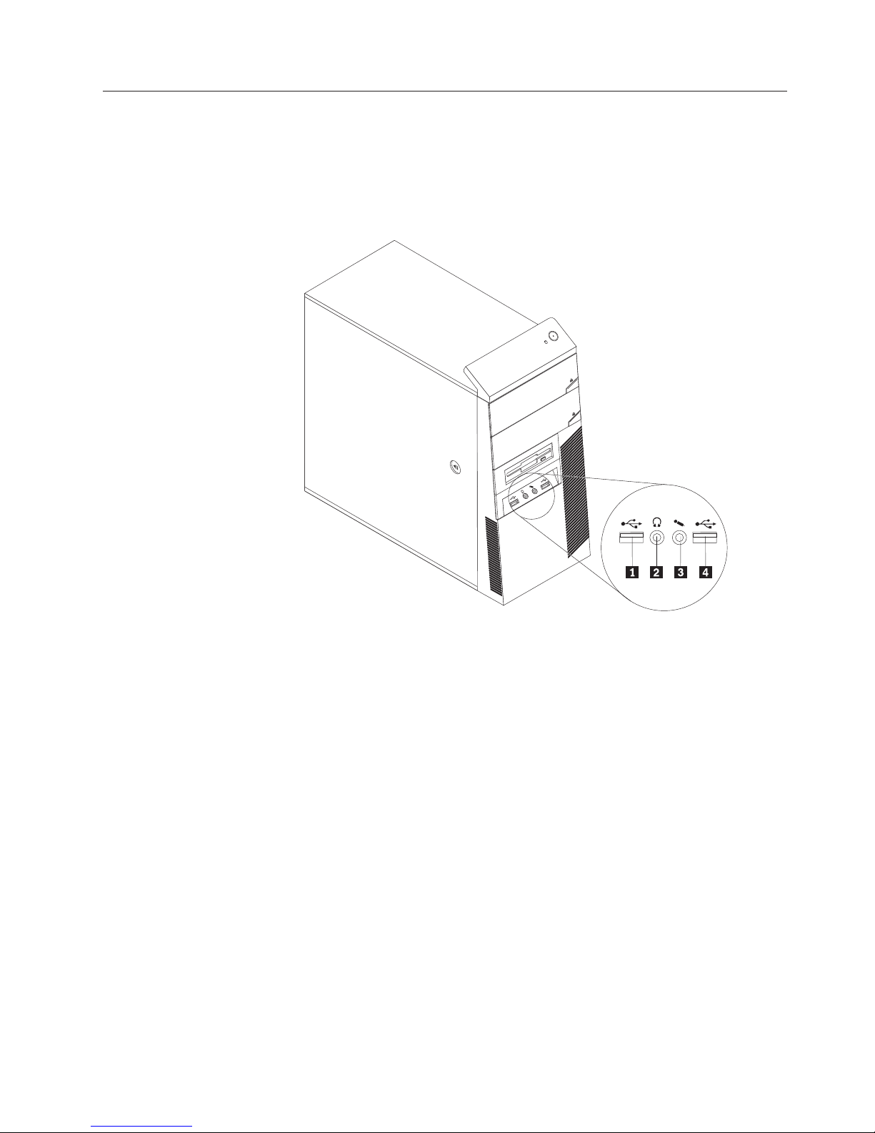
Figure 1 shows the locations of the connectors on the front of your computer.
Note: Not all computer models have the following connectors.
Figure 1. Front connector locations
1 USB connector 3 Microphone connector
2 Headphone connector 4 USB connector
Chapter 1. Product overview 7
Locating connectors on the rear of your computer
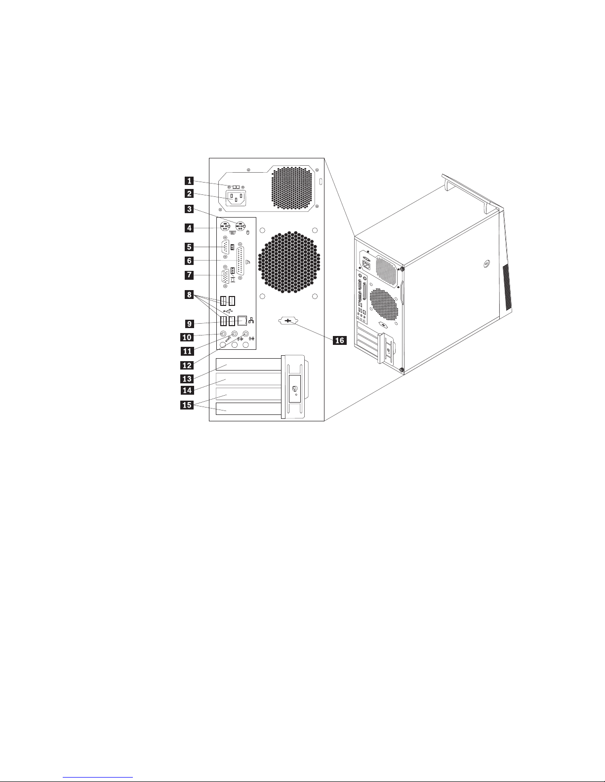
Figure 2 shows the locations of the connectors on the rear of your computer. Some
connectors on the rear of your computer are color-coded to help you determine
where to connect the cables on your computer.
Note: Not all computer models have the following connectors.
Figure 2. Rear connector locations
1 Voltage-selection switch (some models) 9 Ethernet connector
2 Power cord connector 10 Microphone connector
3 Standard mouse connector 11 Audio line-out connector
4 Standard keyboard connector 12 Audio line-in connector
5 Serial port 13 PCI Express x16 graphics card slot
6 Parallel port 14 PCI Express x1 card slot
7 VGA monitor connector 15 PCI card slots (2)
8 USB connectors (4) 16 Serial port (some models)
8 User Guide

Connector Description
Audio line-in connector Used to receive audio signals from an external audio device,
such as a stereo system. When you attach an external audio
device, a cable is connected between the audio line-out
connector of the device and the audio line-in connector of the
computer.
Audio line-out connector Used to send audio signals from the computer to external
devices, such as powered stereo speakers (speakers with
built-in amplifiers), headphones, multimedia keyboards, or the
audio line-in connector on a stereo system or other external
recording devices.
Ethernet connector Used to attach an Ethernet cable for a local area network
(LAN).
Note: To operate the computer within FCC Class B limits, use
a Category 5 Ethernet cable.
Microphone connector Used to attach a microphone to your computer when you want
to record sound or if you use speech-recognition software.
Parallel port Used to attach a parallel printer, a parallel scanner, or other
devices that use a 25-pin parallel port.
Standard keyboard
connector
Used to attach a keyboard that uses a standard keyboard
connector.
Standard mouse connector Used to attach a mouse, a trackball, or other pointing devices
that use a standard mouse connector.
Serial port Used to attach an external modem, a serial printer, or other
devices that use a 9-pin serial port.
USB connector Used to attach a device that requires a Universal Serial Bus
(USB) connector, such as a USB keyboard, a USB mouse, a USB
scanner, or a USB printer. If you have more than six USB
devices, you can purchase a USB hub, which you can use to
connect additional USB devices.
VGA monitor connector Used to attach a VGA monitor or other devices that use a VGA
monitor connector.
Chapter 1. Product overview 9
Locating components
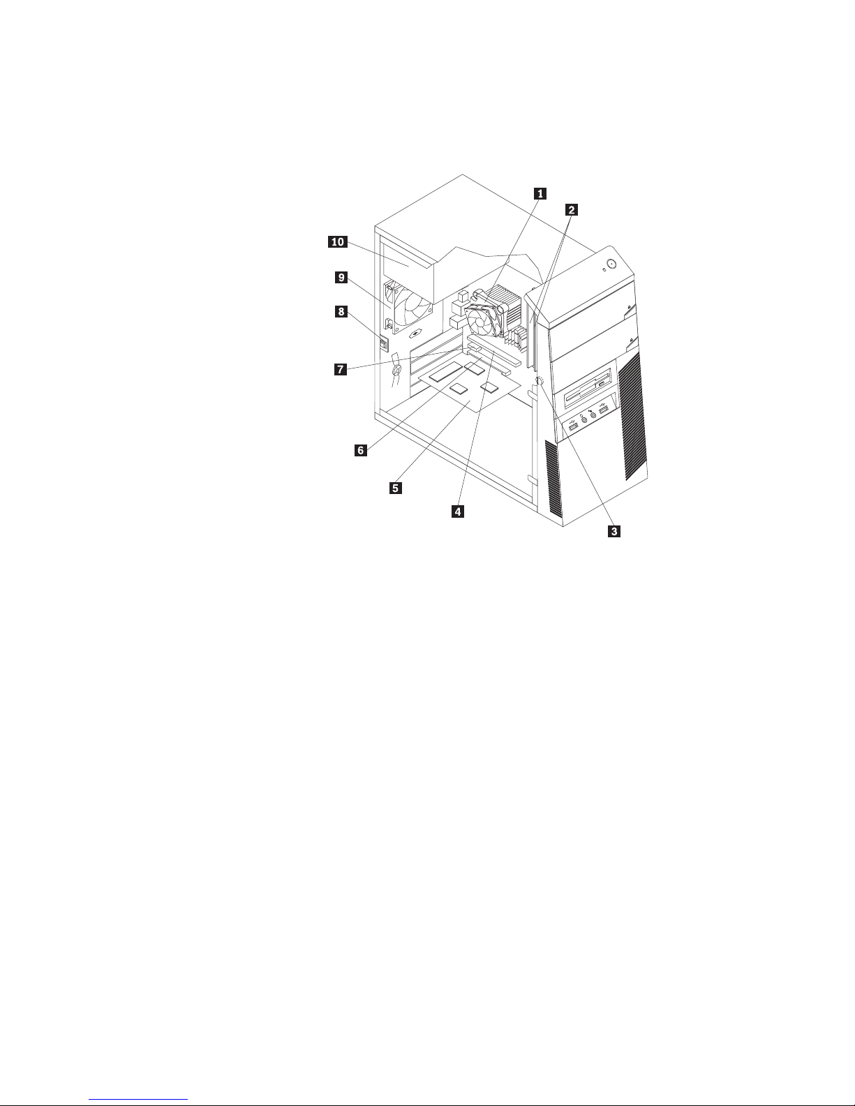
Figure 3 shows the locations of the various components in your computer. To
remove the computer cover, see “Removing the computer cover” on page 14.
Figure 3. Component locations
1 Heat sink and fan assembly 6 PCI card slot
2 Memory modules (2) 7 PCI Express x1 card slot
3 Battery 8 Cover presence switch (Intrusion
switch) (some models)
4 PCI Express x16 graphics card slot 9 Rear fan assembly
5 PCI card 10 Power supply assembly
10 User Guide
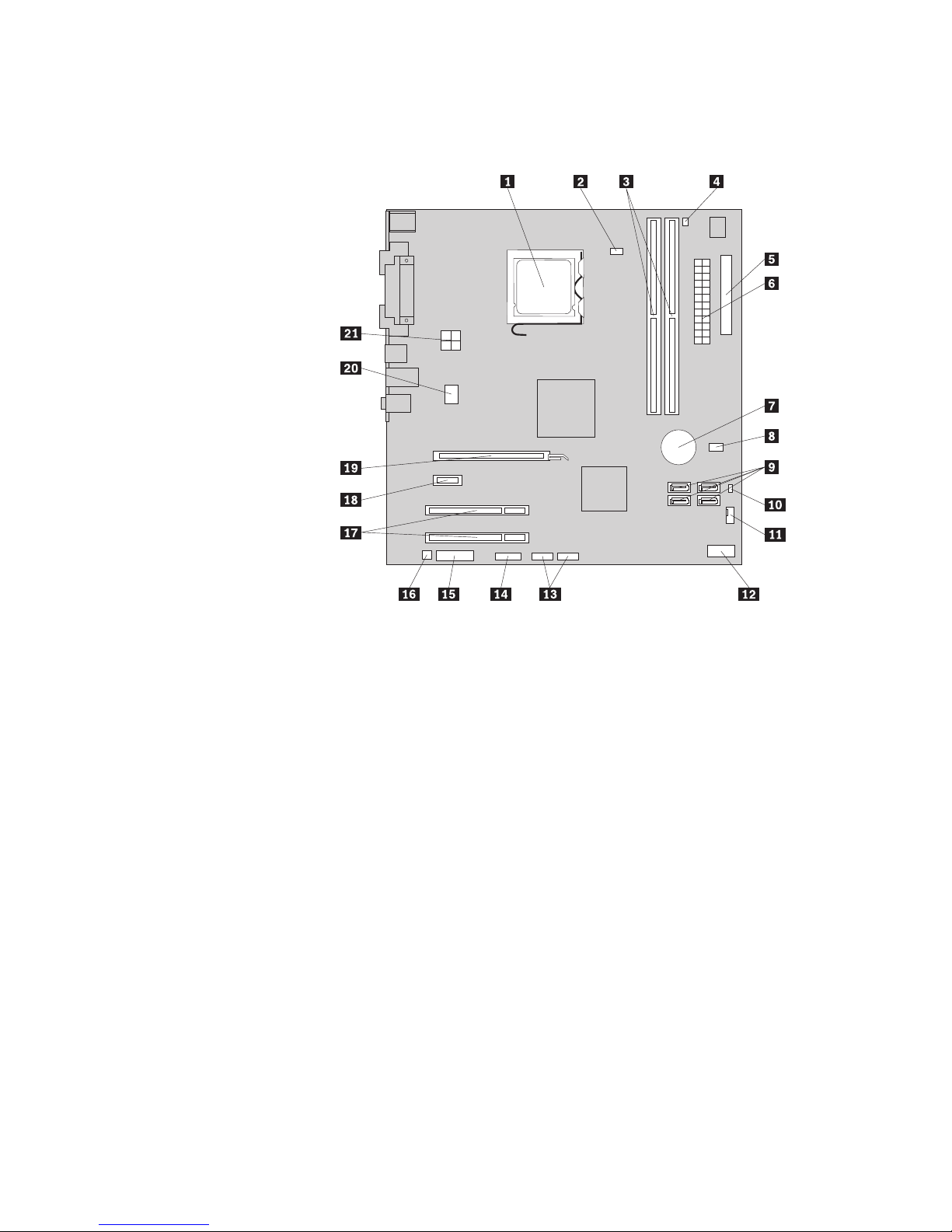
Locating parts on the system board
Figure 4 shows the locations of the parts on the system board.
Figure 4. System board parts locations
1 Microprocessor 12 Front panel connector
2 Microprocessor fan connector 13 Front USB connectors (2)
3 Memory slots (2) 14 Serial (COM 2) connector
4 Thermal sensor connector 15 Front audio connector
5 Diskette drive connector 16 Internal speaker connector
6 24-pin power connector 17 PCI card slots (2)
7 Battery 18 PCI Express x1 card slot
8 Cover presence switch connector
(Intrusion switch connector) (some
models)
9 SATA connectors (4) 20 System fan connector
10 Clear CMOS (Complementary
Metal Oxide Semiconductor)/Recovery
jumper
11 Power fan connector
19 PCI Express x16 graphics card slot
21 4-pin power connector
Chapter 1. Product overview 11

12 User Guide

Chapter 2. Installing options and replacing hardware
This chapter provides instructions for installing options and replacing hardware for
your computer. You can expand the capabilities of your computer by adding
drives, memory modules, or PCI cards. When installing or replacing an option, use
these instructions along with the instructions that come with the option.
Important: Before you install or replace any option, be sure to read and
understand the “Important safety information” in the ThinkCentre Safety
and Warranty Guide. The precautions and guidelines will help you work
safely.
Handling static-sensitive devices
Do not open the static-protective package containing the new part until the
defective part has been removed from the computer and you are ready to install
the new part. Static electricity, although harmless to you, can seriously damage
computer components and parts.
When you handle parts and other computer components, take these precautions to
avoid static-electricity damage:
v Limit your movement. Movement can cause static electricity to build up around
you.
v Always handle parts and other computer components carefully. Handle PCI
cards, memory modules, system boards, and microprocessors by the edges.
Never touch any exposed circuitry.
v Prevent others from touching the parts and other computer components.
v Before you replace a new part, touch the static-protective package containing the
part to a metal expansion-slot cover or other unpainted metal surface on the
computer for at least two seconds. This reduces static electricity in the package
and your body.
v When possible, remove the new part from the static-protective packaging, and
install it directly in the computer without setting the part down. When this is
not possible, place the static-protective package that the part came in on a
smooth, level surface and place the part on it.
v Do not place the part on the computer cover or other metal surface.
Installing options and replacing hardware
This section provides introductions for installing options and replacing hardware
for your computer. When installing or replacing an option, use these instructions
along with the instructions that come with the option.
Attention
Do not open your computer or attempt any repair before reading and understanding the
“Important safety information” in the ThinkCentre Safety and Warranty Guide that came with
your computer. To obtain a copy of the ThinkCentre Safety and Warranty Guide,goto:
http://www.lenovo.com/support
Note: Use only computer parts provided by Lenovo.
© Copyright Lenovo 2009 13
Installing external options
External speakers, a printer, or a scanner can be connected to your computer. For
some external options, you must install additional software in addition to making
the physical connection. When installing an external option, see “Locating
connectors on the front of your computer” on page 7 and “Locating connectors on
the rear of your computer” on page 8 to identify the required connector, and then
use the instructions that come with the option to help you make the connection
and install any software or device drivers that are required for the option.
Removing the computer cover
Attention
Do not open your computer or attempt any repair before reading and understanding the
“Important safety information” in the ThinkCentre Safety and Warranty Guide that came with
your computer. To obtain a copy of the ThinkCentre Safety and Warranty Guide,goto:
http://www.lenovo.com/support
This section provides instructions on how to remove the computer cover.
CAUTION:
Turn off the computer and wait three to five minutes to let the computer cool
before removing the computer cover.
To remove the computer cover:
1. Remove any media from the drives, shut down your operating system, and
turn off all attached devices and the computer.
2. Unplug all power cords from electrical outlets.
3. Disconnect the cables attached to the computer. This includes power cords,
input/output (I/O) cables, and any other cables that are connected to the
computer. See “Locating connectors on the front of your computer” on page 7
and “Locating connectors on the rear of your computer” on page 8.
4. Remove any locking devices, such as a cable lock that secures the computer
cover.
5. If there are thumbscrews that secure the computer cover, remove them.
14 User Guide
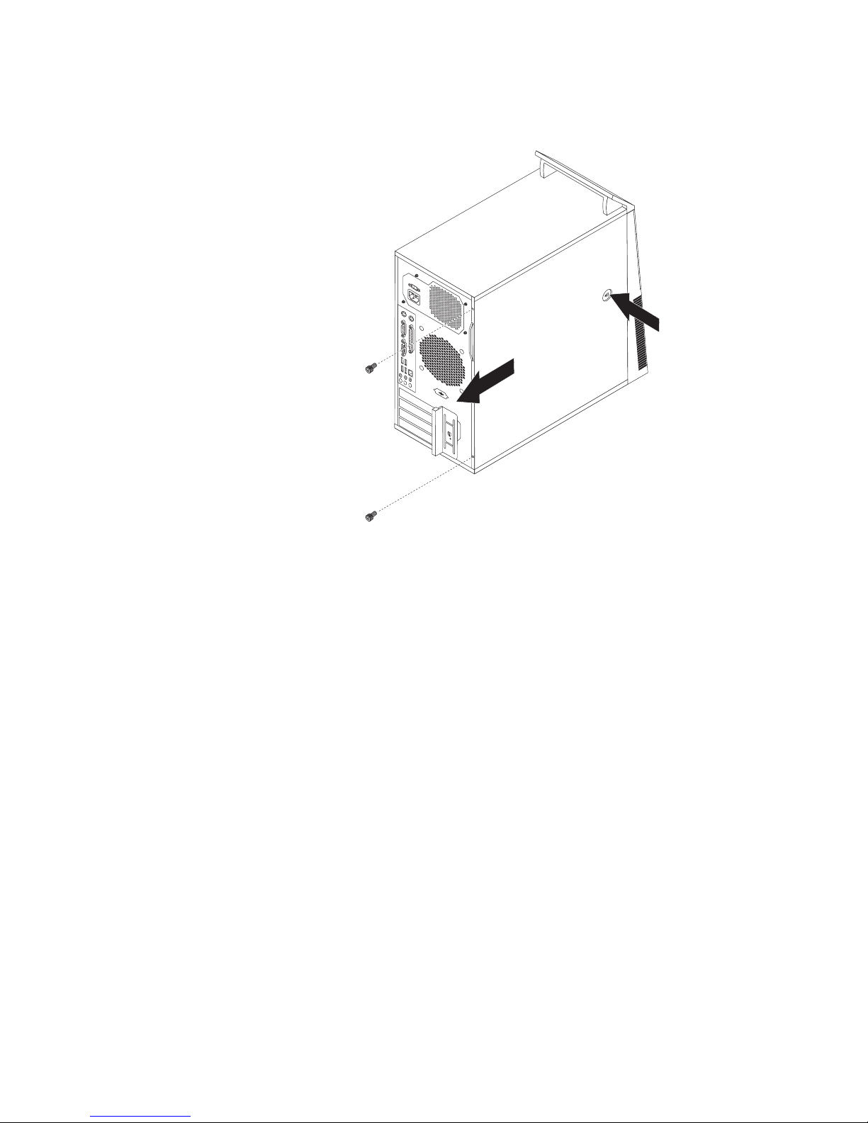
6. Press the cover-release button on the side of the computer cover and slide the
computer cover to the rear to remove.
Figure 5. Removing the computer cover
Chapter 2. Installing options and replacing hardware 15
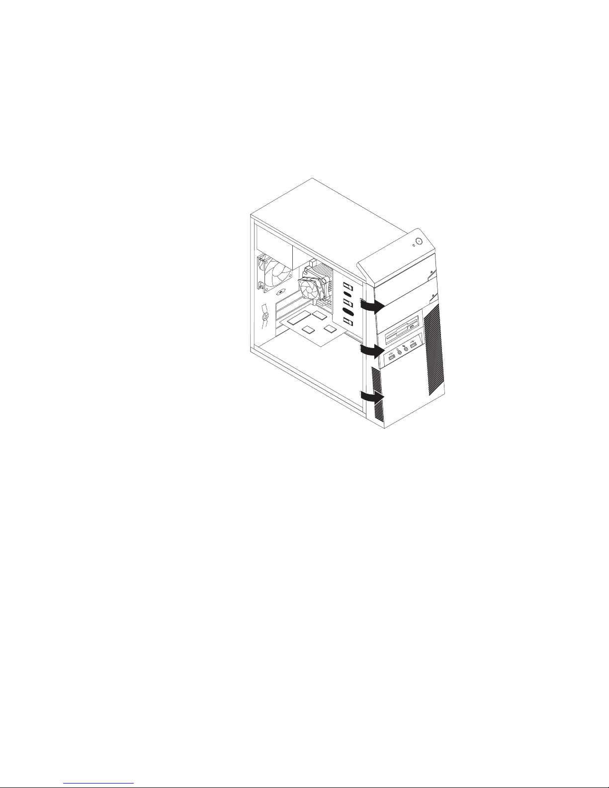
Removing and reinstalling the front bezel
This section provides instructions on how to remove and reinstall the front bezel.
To remove and reinstall the front bezel:
1. Remove the computer cover. See “Removing the computer cover” on page 14.
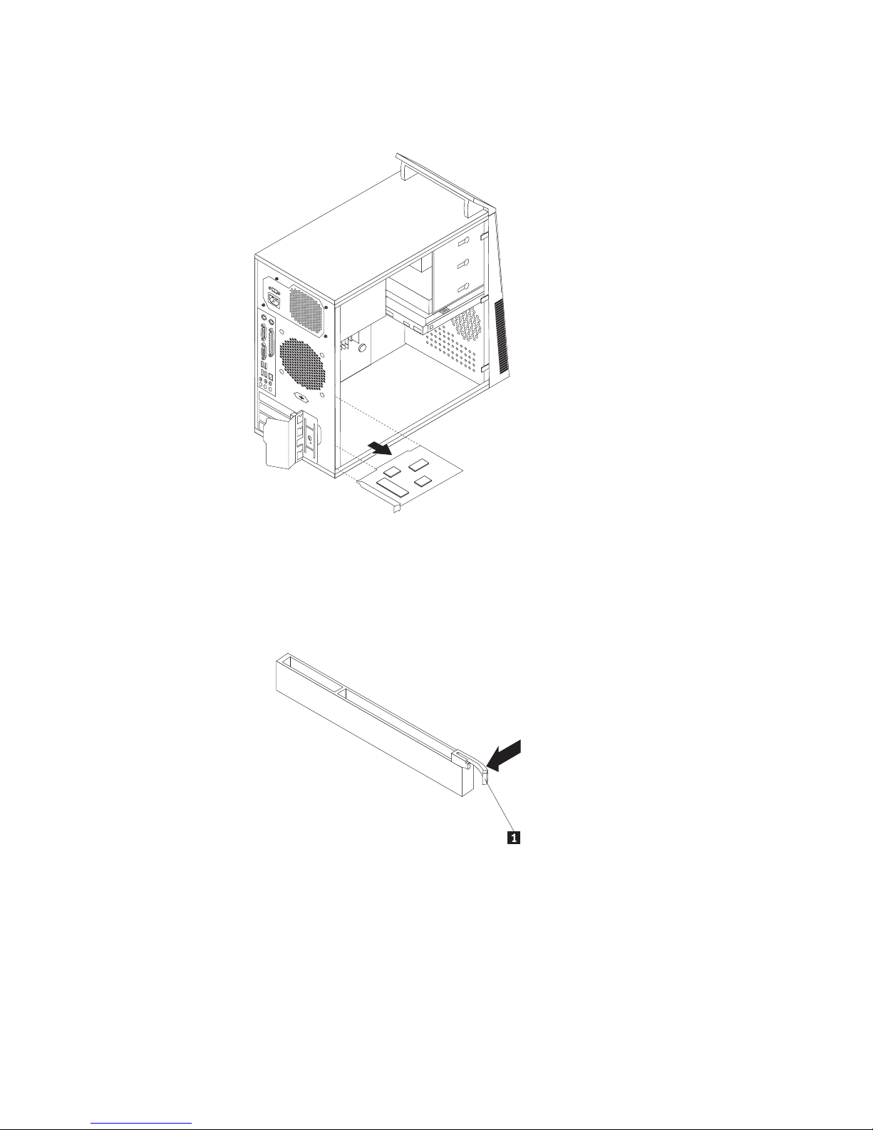
2. Release the three plastic tabs on the left side and pivot the front bezel outward
to remove it.
Figure 6. Removing the front bezel
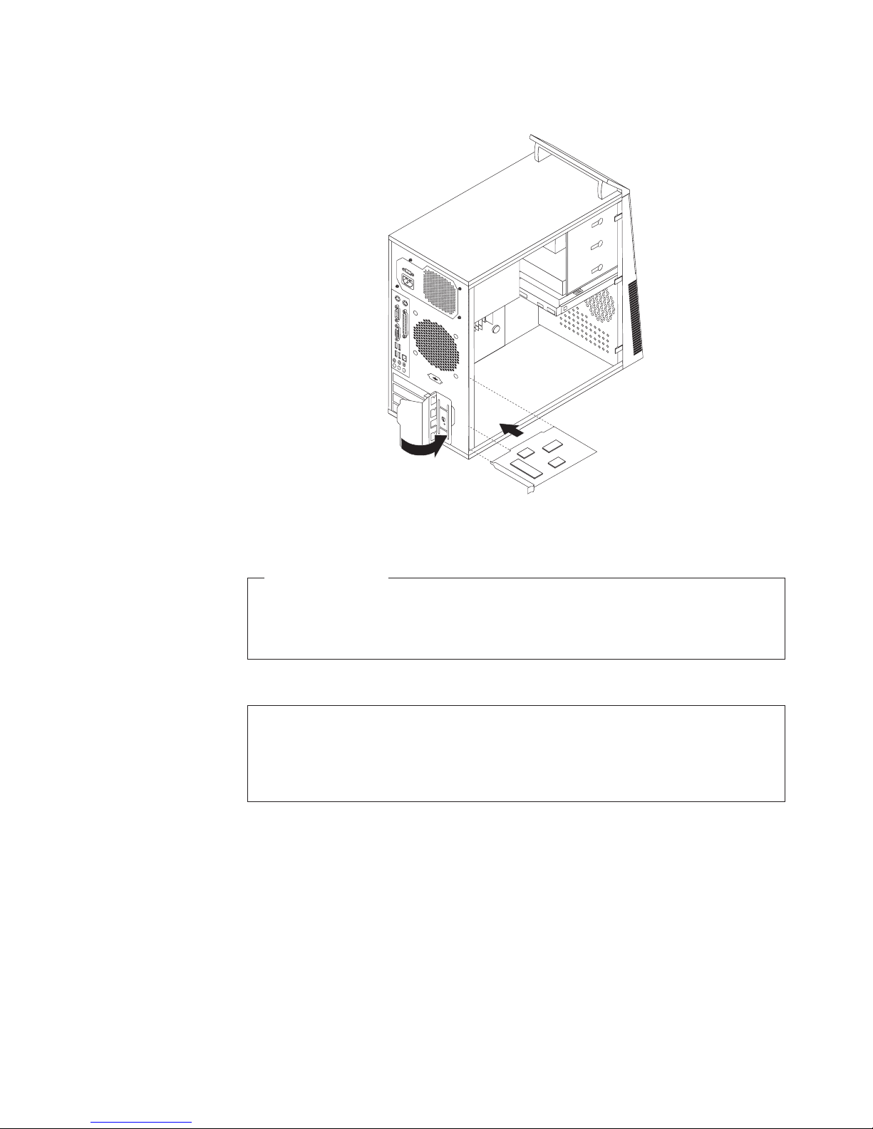
3. To reinstall the front bezel, align the plastic tabs on the right side of the front
bezel with the corresponding holes in the chassis, then pivot the front bezel
inward until it snaps into position on the left side.
4. To complete the installation, go to “Completing the parts replacement” on page
46.
16 User Guide
Installing internal options
Important
Be sure to read and understand “Handling static-sensitive devices” on page
13 before removing the computer cover.
Installing or replacing a PCI card
Attention
Do not open your computer or attempt any repair before reading and understanding the
“Important safety information” in the ThinkCentre Safety and Warranty Guide that came with
your computer. To obtain a copy of the ThinkCentre Safety and Warranty Guide,goto:
http://www.lenovo.com/support
This section provides instructions on how to install or replace a PCI card.
Your computer has two standard PCI card slots, one PCI Express x1 card slot, and
one PCI Express x16 graphics card slot.
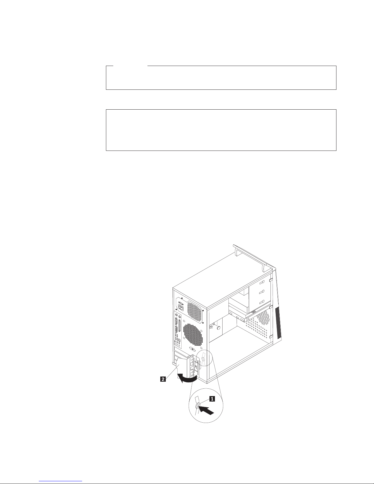
To install or replace a PCI card:
1. Remove the computer cover. See “Removing the computer cover” on page 14.
2. At the rear of the computer, press the release button 1 to open the card latch
2 and remove the slot cover.
Figure 7. Opening the card latch
3. Remove the new PCI card from its static-protective package.
Chapter 2. Installing options and replacing hardware 17
4. Install the new card into the appropriate slot on the system board. See
“Locating parts on the system board” on page 11. If you are replacing a PCI
card, remove the old card currently installed before installing the new one.
Notes:
a. The card fits tightly into the card slot. If necessary, alternately move each
side of the card a small amount until it is fully removed from the card slot.
b. If the card is held in place by a retaining latch, press the card retaining latch
1 as shown to disengage the latch. Grasp the card and gently pull it out
of the slot.
18 User Guide
5. Pivot the card latch to the closed position to secure the cards.
Figure 8. Closing the card latch
What to do next:
v To work with another option, go to the appropriate section.
v To complete the installation, go to “Completing the parts replacement” on
page 46.
Installing or replacing a memory module
Attention
Do not open your computer or attempt any repair before reading and understanding the
“Important safety information” in the ThinkCentre Safety and Warranty Guide that came with
your computer. To obtain a copy of the ThinkCentre Safety and Warranty Guide,goto:
http://www.lenovo.com/support
This section provides instructions on how to install or replace a memory module.
Your computer has two slots for installing or replacing DDR2 DIMMs. When
installing or replacing a memory module, use 1 GB or 2 GB DDR2 DIMMs in any
combination up to a maximum of 4 GB system memory.
To install or replace a memory module:
1. Remove the computer cover. See “Removing the computer cover” on page 14.
Note: For this procedure, it helps to lay the computer on its side.
2. Remove any parts that might prevent access to the memory slots.
3. Locate the memory slots. See “Locating parts on the system board” on page 11.
Chapter 2. Installing options and replacing hardware 19
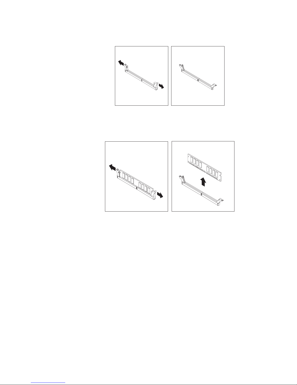
4. Open the retaining clips.
Figure 9. Opening the retaining clips
If you are replacing an old memory module, open the retaining clips and
remove the memory module being replaced as shown.
Figure 10. Removing the memory module
20 User Guide
 Loading...