

Page 1

ThinkCentre
HardwareMaintenanceManual
MachineTypes:3317,4013,4478,5043,5237,5393,5526,and6674.
Page 2

Page 3

ThinkCentre
HardwareMaintenanceManual
MachineTypes:3317,4013,4478,5043,5237,5393,5526,and6674.
Page 4

Note:Beforeusingthisinformationandtheproductitsupports,besuretoreadandunderstandChapter2
“Safetyinformation”onpage3andAppendixA“Notices”onpage207.
FourthEdition(March2011)
©CopyrightLenovo2009,2011.
LENOVOproducts,data,computersoftware,andserviceshavebeendevelopedexclusivelyatprivateexpenseandare
soldtogovernmentalentitiesascommercialitemsasdenedby48C.F .R.2.101withlimitedandrestrictedrightsto
use,reproductionanddisclosure.
LIMITEDANDRESTRICTEDRIGHTSNOTICE:Ifproducts,data,computersoftware,orservicesaredeliveredpursuant
aGeneralServicesAdministration²GSA²contract,use,reproduction,ordisclosureissubjecttorestrictionssetforth
inContractNo.GS-35F-05925.
Page 5

Contents
Chapter1.Aboutthismanual.....1
Importantsafetyinformation..........1
ImportantinformationaboutreplacingtheRoHS
compliantFRUs...............1
Chapter2.Safetyinformation.....3
Generalsafety................3
Electricalsafety...............3
Voltage-selectionswitch............5
Safetyinspectionguide............5
Handlingelectrostaticdischarge-sensitive
devices..................6
Groundingrequirements............6
Safetynotices(multi-lingualtranslations).....6
Chapter3.Generalinformation....29
OnlineBooksfolder.............29
LenovoThinkVantageTools.........29
ThinkVantageProductivityCenter.......29
LenovoWelcome..............30
AccessHelp...............30
Additionalinformationresources.......30
Specications...............30
Chapter4.Generalcheckout.....33
Problemdeterminationtips..........33
Chapter5.Diagnostics........35
LenovoThinkVantageToolbox........35
LenovoSystemToolbox...........35
PC-DoctorforRescueandRecovery......36
PC-DoctorforDOS.............36
Creatingadiagnosticdisc........36
Runningthediagnosticprogramfroma
diagnosticdisc.............36
Navigatingthroughthediagnostics
programs...............37
Runningtests.............37
Viewingthetestlog...........38
Chapter6.UsingtheSetupUtility
program................39
StartingtheSetupUtilityprogram.......39
Viewingorchangingsettings.........39
Usingpasswords..............39
Passwordconsiderations.........40
Power-onpassword...........40
Administratorpassword.........40
Setting,changing,ordeletingapassword..40
Enablingordisablingadevice........40
Selectingastartupdevice..........41
Selectingatemporarystartupdevice....41
Viewingorchangingthestartupdevice
sequence...............41
ExitingtheSetupUtilityprogram.......42
Chapter7.Symptom-to-FRUindex.43
Harddiskdrivebooterror..........43
Powersupplyproblems...........43
Diagnosticerrorcodes...........43
Beepsymptoms..............61
POSTerrorcodes.............62
Miscellaneouserrormessages........63
Undeterminedproblems...........65
Chapter8.ReplacingFRUs......67
Locatingconnectorsonthefrontofyour
computer.................67
Locatingconnectorsontherearofyour
computer.................67
Removingthecomputercover........68
Locatingcomponents............69
Locatingpartsonthesystemboard......70
Removingandreinstallingthefrontbezel....71
Installingorreplacingamemorymodule....72
InstallingorreplacingaPCIcard.......74
Replacingthebattery............76
Replacingthepowersupplyassembly.....77
Replacingtheheatsinkandfanassembly....78
Replacingthemicroprocessor........80
Replacingthesystemboard.........82
Replacingtheprimaryharddiskdrive......83
Replacingthesecondaryharddiskdrive....85
Replacingtheopticaldrive..........87
ConnectingaSATAdrive.........89
Replacingthecardreader..........89
Replacingthefrontfanassembly.......90
Replacingtherearfanassembly........92
Replacingtheinternalspeaker........94
ReplacingthefrontaudioandUSBassembly..96
CompletingtheFRUreplacement.......97
Chapter9.FRUlists.........99
Overall:MT3317,4013,4478,5043,5237,5393,
5526,and6674..............99
MechanicalFRUs.............112
©CopyrightLenovo2009,2011
iii
Page 6

KeyboardandMouse............118
AdaptersandmiscellaneousFRUs.......153
PowerCords...............154
Recoverydiscs..............161
WindowsXPProfessionalRecoveryCD...161
WindowsVista32HomeBasicRecovery
CD.................166
WindowsVistaHomeBasic32withMSofce
starter2010RecoveryCD........166
WindowsVistaBusiness32RecoveryCD..166
WindowsVistaBusiness32OfceStarter
2010RecoveryCD...........168
Windows7HomeBasic32RecoveryCD..169
Windows7HomeBasic32OfceStarter2010
RecoveryCD.............171
Windows7HomePremium32Recovery
CD.................173
Windows7HomePremium32OfceStarter
2010RecoveryCD...........176
Windows7Professional32RecoveryCD..178
Windows7Professional32withMSofce
starter2010RecoveryCD........184
Windows7Professional64RecoveryCD..189
Windows7Professional64withMSofce
starter2010RecoveryCD........192
Windows7HomePremium64Recovery
CD.................194
Windows7HomePremium64withMSOfce
Starter2010RecoveryCD........196
Windows7Starter32RecoveryCD....199
Windows7Starter32OfceStarterRecovery
CD.................200
Chapter10.Additionalservice
information.............203
Securityfeatures..............203
HardwarecontrolledPasswords......203
Operatingsystempassword.......203
Vitalproductdata............203
BIOSlevels................203
Updating(ashing)BIOSfromadisc......203
Updating(ashing)BIOSfromyouroperating
system..................204
RecoveringfromaPOST/BIOSupdatefailure..204
Powermanagement............205
Automaticcongurationandpowerinterface
(ACPI)BIOS..............205
AutomaticPower-Onfeatures.......205
AppendixA.Notices........207
Televisionoutputnotice...........208
Trademarks................208
ivThinkCentreHardwareMaintenanceManual
Page 7
Chapter1.Aboutthismanual
ThismanualcontainsserviceandreferenceinformationforThinkCentre®computermachinetypeslisted
onthefrontcover.AlltheinformationinthismanualisintendedonlyfortrainedServiceProviderswhoare
familiarwithLenovo®computerproducts.Beforeusingthisinformationandtheproductitsupports,besure
toreadandunderstandtheChapter2“Safetyinformation”onpage3
The“Symptom-to-FRUIndex”chapterandthe“Additionalserviceinformation”chapterapplytoall
ThinkCentrecomputers.
Thismanualincludesacompleteeldreplaceableunit(FRU)partnumberlistforeachmachinetypelistedon
thefrontcover.IfyouhaveInternetaccess,theFRUpartnumberlistsarealsoavailableat:
http://www.lenovo.com/support
Importantsafetyinformation
Besuretoreadandunderstandallcautionanddangerstatementsinthismanualbeforeperforminganyof
theinstructions.
VeuillezliretouteslesconsignesdetypeDANGERetATTENTIONduprésentdocumentavantd'exécuter
lesinstructions.
LesenSieunbedingtalleHinweisevomTyp"ACHTUNG"oder"VORSICHT"indieserDokumentation,bevor
SieirgendwelcheVorgängedurchführen
andAppendixA“Notices”onpage207.
LeggereleistruzioniintrodottedaATTENZIONEePERICOLOpresentinelmanualeprimadieseguireuna
qualsiasidelleistruzioni
Certique-sedelertodasasinstruçõesdecuidadoeperigonestemanualantesdeexecutarqualquer
umadasinstruções
Esimportantequeleatodaslasdeclaracionesdeprecauciónydepeligrodeestemanualantesdeseguir
lasinstrucciones.
ImportantinformationaboutreplacingtheRoHScompliantFRUs
RoHS,theRestrictionofHazardousSubstancesinElectricalandElectronicEquipmentDirective
(2002/95/EC)isaEuropeanUnionlegalrequirementaffectingtheglobalelectronicsindustry.RoHS
requirementsmustbeimplementedonLenovoproductsplacedonthemarketandsoldinthe
EuropeanUnionafterJune2006.ProductsonthemarketbeforeJune2006arenotrequiredto
haveRoHScompliantparts.Ifthepartsarenotcompliantoriginally,replacementpartscanalso
©CopyrightLenovo2009,2011
1
Page 8
benoncompliant,butinallcases,ifthepartsarecompliant,thereplacementpartsmustalsobe
compliant.
Note:RoHSandnon-RoHSFRUpartnumberswiththesametandfunctionareidentiedwithunique
FRUpartnumbers.
LenovoplanstotransitiontoRoHScompliancewellbeforetheimplementationdateandexpectsitssuppliers
tobereadytosupportLenovo'srequirementsandscheduleintheEU.Productssoldin2005,willcontain
someRoHScompliantFRUs.ThefollowingstatementpertainstotheseproductsandanyproductLenovo
producescontainingRoHScompliantparts.
RoHScompliantThinkCentrepartshaveuniqueFRUpartnumbers.BeforeorafterJune,2006,failedRoHS
compliantpartsmustalwaysbereplacedusingRoHScompliantFRUs,soonlytheFRUsidentiedas
compliantinthesystemHMMordirectsubstitutionsforthoseFRUscanbeused.
ProductsmarketedbeforeJune2006ProductsmarketedafterJune2006
Currentororiginalpart
Non-RoHSCanbeNon-RoHS
Non-RoHSCanbeRoHS
Non-RoHSCansubtoRoHS
RoHSMustbeRoHS
ReplacementFRU
Currentororiginalpart
MustbeRoHSMustbeRoHS
ReplacementFRU
Note:AdirectsubstitutionisapartwithadifferentFRUpartnumberthatisautomaticallyshippedbythe
distributioncenteratthetimeoforder.
2ThinkCentreHardwareMaintenanceManual
Page 9

Chapter2.Safetyinformation
Thischaptercontainsthesafetyinformationthatyouneedtoreadandunderstandbeforeservicinga
computer.
Generalsafety
Followtheserulestoensuregeneralsafety:
•Observegoodhousekeepingintheareaofthemachinesduringandaftermaintenance.
•Whenliftinganyheavyobject:
1.Ensureyoucanstandsafelywithoutslipping.
2.Distributetheweightoftheobjectequallybetweenyourfeet.
3.Useaslowliftingforce.Nevermovesuddenlyortwistwhenyouattempttolift.
4.Liftbystandingorbypushingupwithyourlegmuscles;thisactionremovesthestrainfromthe
musclesinyourback.Donotattempttoliftanyobjectsthatweighmorethan16kg(35lb)orobjects
thatyouthinkaretooheavyforyou.
•Donotperformanyactionthatcauseshazardstothecustomer,orthatmakestheequipmentunsafe.
•Beforeyoustartthemachine,ensurethatotherservicerepresentativesandthecustomer'spersonnelare
notinahazardousposition.
•Placeremovedcoversandotherpartsinasafeplace,awayfromallpersonnel,whileyouareservicing
themachine.
•Keepyourtoolcaseawayfromwalkareassothatotherpeoplewillnottripoverit.
•Donotwearlooseclothingthatcanbetrappedinthemovingpartsofamachine.Ensurethatyoursleeves
arefastenedorrolledupaboveyourelbows.Ifyourhairislong,fastenit.
•Inserttheendsofyournecktieorscarfinsideclothingorfastenitwithanonconductiveclip,approximately
8centimeters(3inches)fromtheend.
•Donotwearjewelry,chains,metal-frameeyeglasses,ormetalfastenersforyourclothing.
Remember:Metalobjectsaregoodelectricalconductors.
•Wearsafetyglasseswhenyouare:hammering,drilling,soldering,cuttingwire,attachingsprings,using
solvents,orworkinginanyotherconditionsthatmightbehazardoustoyoureyes.
•Afterservice,reinstallallsafetyshields,guards,labels,andgroundwires.Replaceanysafetydevice
thatiswornordefective.
•Reinstallallcoverscorrectlybeforereturningthemachinetothecustomer.
Electricalsafety
CAUTION:
Electricalcurrentfrompower,telephone,andcommunicationcablescanbehazardous.Toavoid
personalinjuryorequipmentdamage,disconnecttheattachedpowercords,telecommunication
systems,networks,andmodemsbeforeyouopentheserver/workstationcovers,unlessinstructed
otherwiseintheinstallationandcongurationprocedures.
Observethefollowingruleswhenworkingonelectricalequipment.
©CopyrightLenovo2009,2011
3
Page 10

Important:Useonlyapprovedtoolsandtestequipment.Somehandtoolshavehandlescoveredwithasoft
materialthatdoesnotinsulateyouwhenworkingwithliveelectricalcurrents.Manycustomershave,near
theirequipment,rubberoormatsthatcontainsmallconductiveberstodecreaseelectrostaticdischarges.
Donotusethistypeofmattoprotectyourselffromelectricalshock.
•Findtheroomemergencypower-off(EPO)switch,disconnectingswitch,orelectricaloutlet.Ifanelectrical
accidentoccurs,youcanthenoperatetheswitchorunplugthepowercordquickly.
•Donotworkaloneunderhazardousconditionsornearequipmentthathashazardousvoltages.
•Disconnectallpowerbefore:
–Performingamechanicalinspection
–Workingnearpowersupplies
–RemovingorinstallingFieldReplaceableUnits
•Beforeyoustarttoworkonthemachine,unplugthepowercord.Ifyoucannotunplugit,askthecustomer
topower-offthewallboxthatsuppliespowertothemachineandtolockthewallboxintheoffposition.
•Ifyouneedtoworkonamachinethathasexposedelectricalcircuits,observethefollowingprecautions:
–Ensurethatanotherperson,familiarwiththepower-offcontrols,isnearyou.
Remember:Anotherpersonmustbetheretoswitchoffthepower,ifnecessary.
–Useonlyonehandwhenworkingwithpowered-onelectricalequipment;keeptheotherhandinyour
pocketorbehindyourback.
Remember:Theremustbeacompletecircuittocauseelectricalshock.Byobservingtheaboverule,
youmaypreventacurrentfrompassingthroughyourbody.
–Whenusingtesters,setthecontrolscorrectlyandusetheapprovedprobeleadsandaccessoriesfor
thattester.
–Standonsuitablerubbermats(obtainedlocally,ifnecessary)toinsulateyoufromgroundssuchas
metaloorstripsandmachineframes.
Observethespecialsafetyprecautionswhenyouworkwithveryhighvoltages;theseinstructionsarein
thesafetysectionsofmaintenanceinformation.Useextremecarewhenmeasuringhighvoltages.
•Regularlyinspectandmaintainyourelectricalhandtoolsforsafeoperationalcondition.
•Donotusewornorbrokentoolsandtesters.
•Neverassumethatpowerhasbeendisconnectedfromacircuit.First,checkthatithasbeenpowered-off.
•Alwayslookcarefullyforpossiblehazardsinyourworkarea.Examplesofthesehazardsaremoistoors,
nongroundedpowerextensioncables,powersurges,andmissingsafetygrounds.
•Donottouchliveelectricalcircuitswiththereectivesurfaceofaplasticdentalmirror.Thesurfaceis
conductive;suchtouchingcancausepersonalinjuryandmachinedamage.
•Donotservicethefollowingpartswiththepoweronwhentheyareremovedfromtheirnormaloperating
placesinamachine:
–Powersupplyunits
–Pumps
–Blowersandfans
–Motorgenerators
andsimilarunits.(Thispracticeensurescorrectgroundingoftheunits.)
•Ifanelectricalaccidentoccurs:
–Usecaution;donotbecomeavictimyourself.
–Switchoffpower.
–Sendanotherpersontogetmedicalaid.
4ThinkCentreHardwareMaintenanceManual
Page 11

Voltage-selectionswitch
Somecomputersareequippedwithavoltage-selectionswitchlocatednearthepower-cordconnection
pointonthecomputer.Ifyourcomputerhasavoltage-selectionswitch,ensurethatyousettheswitchto
matchthevoltageavailableatyourelectricaloutlet.Settingthevoltage-selectionswitchincorrectlycan
causepermanentdamagetothecomputer.
Ifyourcomputerdoesnothaveavoltage-selectionswitch,yourcomputerisdesignedtooperateonlyatthe
voltageprovidedinthecountryorregionwherethecomputerwasoriginallypurchased.
Ifyourelocateyourcomputertoanothercountry,beawareofthefollowing:
•Ifyourcomputerdoesnothaveavoltage-selectionswitch,donotconnectthecomputertoanelectrical
outletuntilyouhaveveriedthatthevoltageprovidedisthesameasitwasinthecountryorregion
wherethecomputerwasoriginallypurchased.
•Ifyourcomputerhasavoltage-selectionswitch,donotconnectthecomputertoanelectricaloutletuntil
youhaveveriedthatthevoltage-selectionswitchissettomatchthevoltageprovidedinthatcountry
orregion.
Ifyouarenotsureofthevoltageprovidedatyourelectricaloutlet,contactyourlocalelectriccompanyor
refertoofcialWebsitesorotherliteraturefortravelerstothecountryorregionwhereyouarelocated.
Safetyinspectionguide
Theintentofthisinspectionguideistoassistyouinidentifyingpotentiallyunsafeconditionsonthese
products.Eachmachine,asitwasdesignedandbuilt,hadrequiredsafetyitemsinstalledtoprotectusers
andservicepersonnelfrominjury.Thisguideaddressesonlythoseitems.However,goodjudgmentshould
beusedtoidentifypotentialsafetyhazardsduetoattachmentoffeaturesoroptionsnotcoveredbythis
inspectionguide.
Ifanyunsafeconditionsarepresent,youmustdeterminehowserioustheapparenthazardcouldbeand
whetheryoucancontinuewithoutrstcorrectingtheproblem.
Considertheseconditionsandthesafetyhazardstheypresent:
•Electricalhazards,especiallyprimarypower(primaryvoltageontheframecancauseseriousorfatal
electricalshock).
•Explosivehazards,suchasadamagedCRTfaceorbulgingcapacitor
•Mechanicalhazards,suchaslooseormissinghardware
Theguideconsistsofaseriesofstepspresentedinachecklist.Beginthecheckswiththepoweroff,and
thepowercorddisconnected.
Checklist:
1.Checkexteriorcoversfordamage(loose,broken,orsharpedges).
2.Power-offthecomputer.Disconnectthepowercord.
3.Checkthepowercordfor:
a.Athird-wiregroundconnectoringoodcondition.Useametertomeasurethird-wireground
continuityfor0.1ohmorlessbetweentheexternalgroundpinandframeground.
b.Thepowercordshouldbetheappropriatetypeasspeciedinthepartslistings.
c.Insulationmustnotbefrayedorworn.
4.Removethecover.
Chapter2.Safetyinformation5
Page 12

5.Checkforanyobviousalterations.Usegoodjudgmentastothesafetyofanyalterations.
6.Checkinsidetheunitforanyobviousunsafeconditions,suchasmetallings,contamination,wateror
otherliquids,orsignsofreorsmokedamage.
7.Checkforworn,frayed,orpinchedcables.
8.Checkthatthepower-supplycoverfasteners(screwsorrivets)havenotbeenremovedortamperedwith.
Handlingelectrostaticdischarge-sensitivedevices
Anycomputerpartcontainingtransistorsorintegratedcircuits(ICs)shouldbeconsideredsensitiveto
electrostaticdischarge(ESD).ESDdamagecanoccurwhenthereisadifferenceinchargebetweenobjects.
ProtectagainstESDdamagebyequalizingthechargesothatthemachine,thepart,theworkmat,andthe
personhandlingthepartareallatthesamecharge.
Notes:
1.Useproduct-specicESDprocedureswhentheyexceedtherequirementsnotedhere.
2.MakesurethattheESDprotectivedevicesyouusehavebeencertied(ISO9000)asfullyeffective.
WhenhandlingESD-sensitiveparts:
•Keepthepartsinprotectivepackagesuntiltheyareinsertedintotheproduct.
•Avoidcontactwithotherpeoplewhilehandlingthepart.
•Wearagroundedwriststrapagainstyourskintoeliminatestaticonyourbody.
•Preventthepartfromtouchingyourclothing.Mostclothingisinsulativeandretainsachargeevenwhen
youarewearingawriststrap.
•Usetheblacksideofagroundedworkmattoprovideastatic-freeworksurface.Thematisespecially
usefulwhenhandlingESD-sensitivedevices.
•Selectagroundingsystem,suchasthoselistedbelow,toprovideprotectionthatmeetsthespecic
servicerequirement.
Note:TheuseofagroundingsystemisdesirablebutnotrequiredtoprotectagainstESDdamage.
–AttachtheESDgroundcliptoanyframeground,groundbraid,orgreen-wireground.
–UseanESDcommongroundorreferencepointwhenworkingonadouble-insulatedor
battery-operatedsystem.Youcanusecoaxorconnector-outsideshellsonthesesystems.
–Usetheroundground-prongoftheacplugonac-operatedcomputers.
Groundingrequirements
Electricalgroundingofthecomputerisrequiredforoperatorsafetyandcorrectsystemfunction.Proper
groundingoftheelectricaloutletcanbeveriedbyacertiedelectrician.
Safetynotices(multi-lingualtranslations)
Thecautionanddangersafetynoticesinthissectionareprovidedinthefollowinglanguages:
•English
•Arabic
•Brazilian/Portuguese
•Chinese(simplied)
•Chinese(traditional)
6ThinkCentreHardwareMaintenanceManual
Page 13
•French
•German
•Hebrew
•Italian
•Korean
•Spanish
DANGER
Electricalcurrentfrompower,telephoneandcommunicationcablesishazardous.
Toavoidashockhazard:
•Donotconnectordisconnectanycablesorperforminstallation,maintenance,orreconguration
ofthisproductduringanelectricalstorm.
•Connectallpowercordstoaproperlywiredandgroundedelectricaloutlet.
•Connecttoproperlywiredoutletsanyequipmentthatwillbeattachedtothisproduct.
•Whenpossible,useonehandonlytoconnectordisconnectsignalcables.
•Neverturnonanyequipmentwhenthereisevidenceofre,water,orstructuraldamage.
•Disconnecttheattachedpowercords,telecommunicationssystems,networks,andmodems
beforeyouopenthedevicecovers,unlessinstructedotherwiseintheinstallationandconguration
procedures.
•Connectanddisconnectcablesasdescribedinthefollowingtableswheninstalling,moving,or
openingcoversonthisproductorattacheddevices.
ToConnectToDisconnect
1.T urneverythingOFF .
2.First,attachallcablestodevices.
3.Attachsignalcablestoconnectors.
4.Attachpowercordstooutlet.
5.T urndeviceON.
1.T urneverythingOFF .
2.First,removepowercordsfromoutlet.
3.Removesignalcablesfromconnectors.
4.Removeallcablesfromdevices.
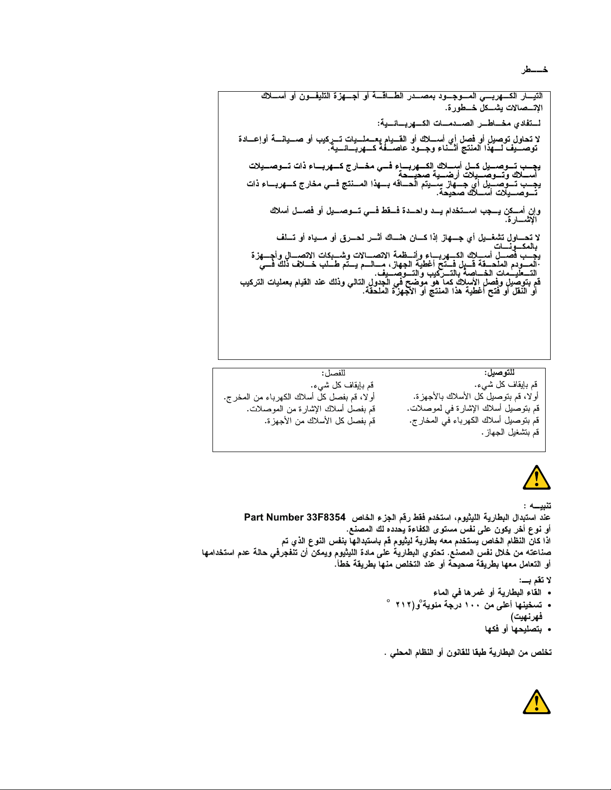
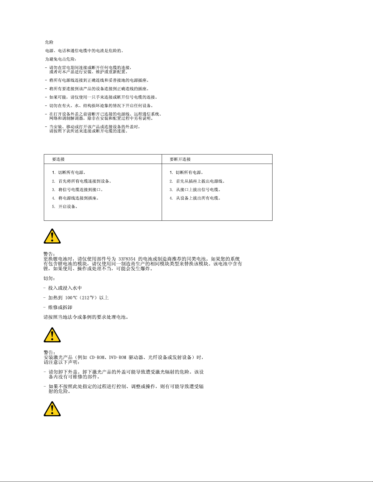
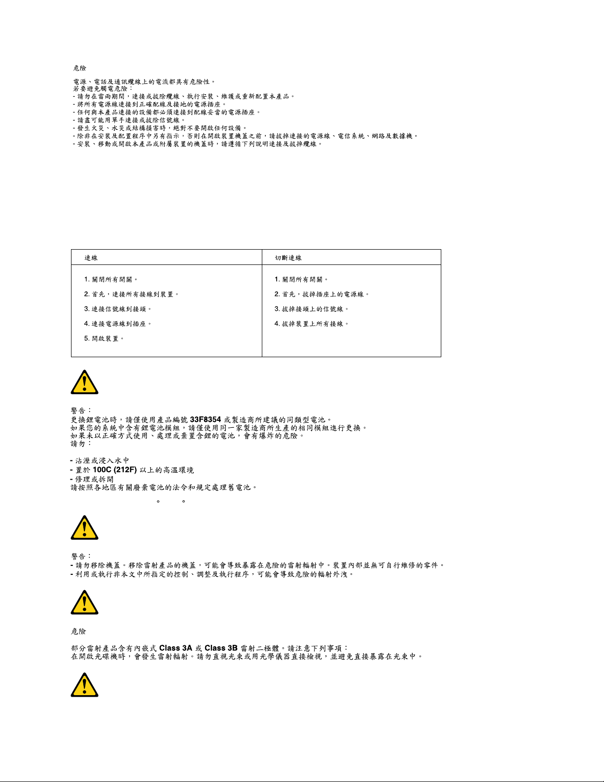
CAUTION:
Whenreplacingthelithiumbattery,useonlyPartNumber45C1566oranequivalenttypebattery
recommendedbythemanufacturer.Ifyoursystemhasamodulecontainingalithiumbattery,replace
itonlywiththesamemoduletypemadebythesamemanufacturer.Thebatterycontainslithiumand
canexplodeifnotproperlyused,handled,ordisposedof.Donot:
•Throworimmerseintowater
•Heattomorethan100°C(212°F)
•Repairordisassemble
Disposeofthebatteryasrequiredbylocalordinancesorregulations.
Chapter2.Safetyinformation7
Page 14
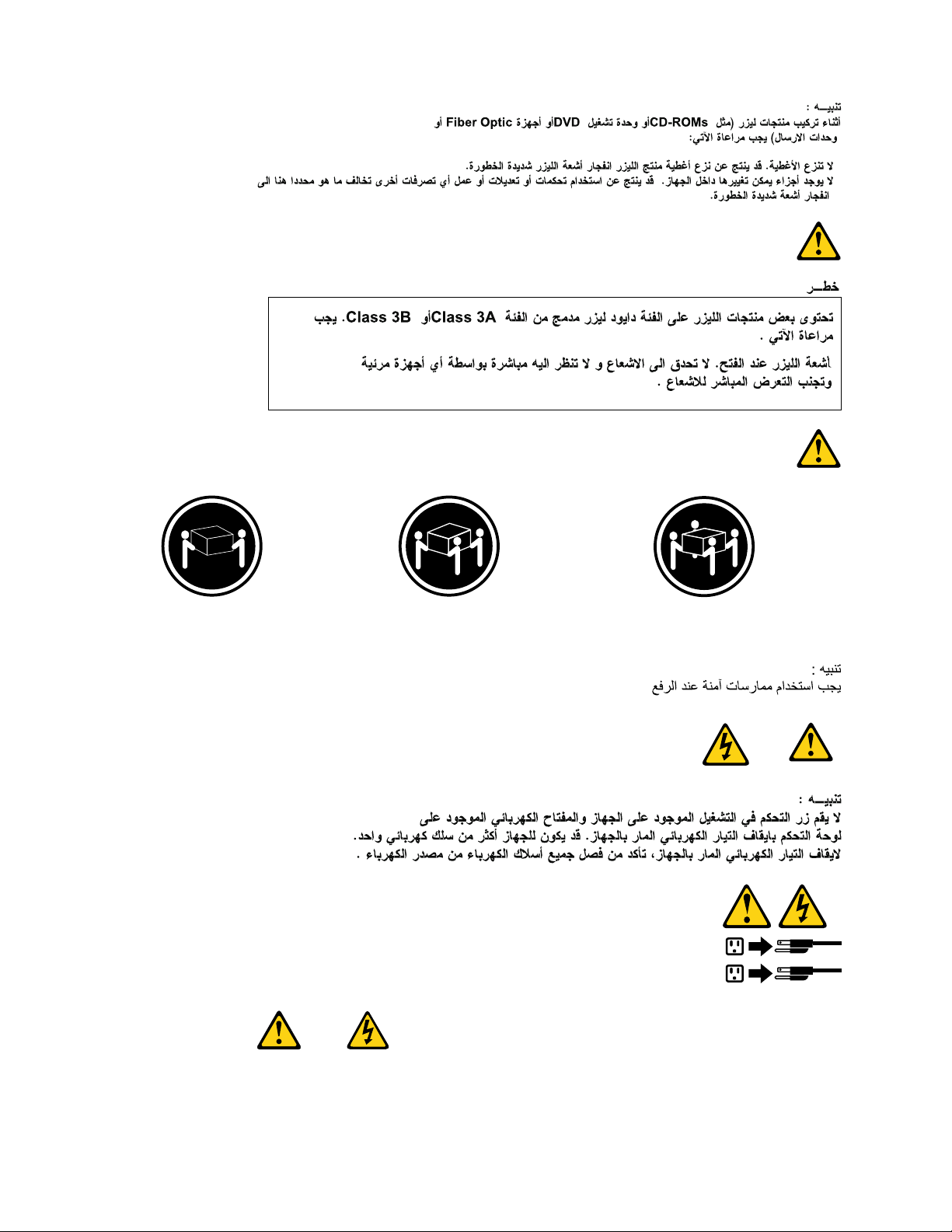
CAUTION:
1
2
Whenlaserproducts(suchasCD-ROMs,DVD-ROMdrives,beropticdevices,ortransmitters)are
installed,notethefollowing:
•Donotremovethecovers.Removingthecoversofthelaserproductcouldresultinexposureto
hazardouslaserradiation.Therearenoserviceablepartsinsidethedevice.
•Useofcontrolsoradjustmentsorperformanceofproceduresotherthanthosespeciedherein
mightresultinhazardousradiationexposure.
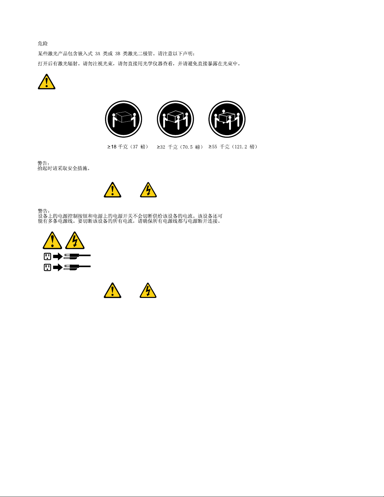
DANGER
SomelaserproductscontainanembeddedClass3AorClass3Blaserdiode.Notethefollowing:
Laserradiationwhenopen.Donotstareintothebeam,donotviewdirectlywithoptical
instruments,andavoiddirectexposuretothebeam.
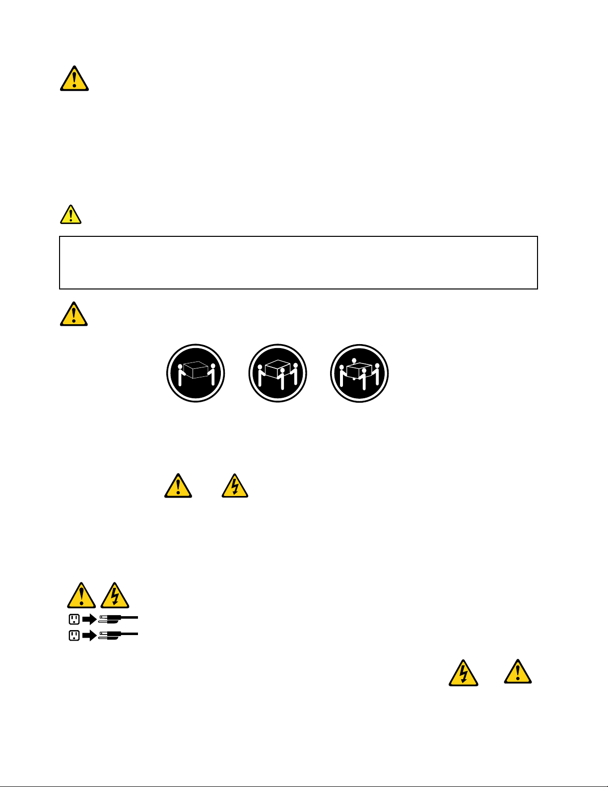
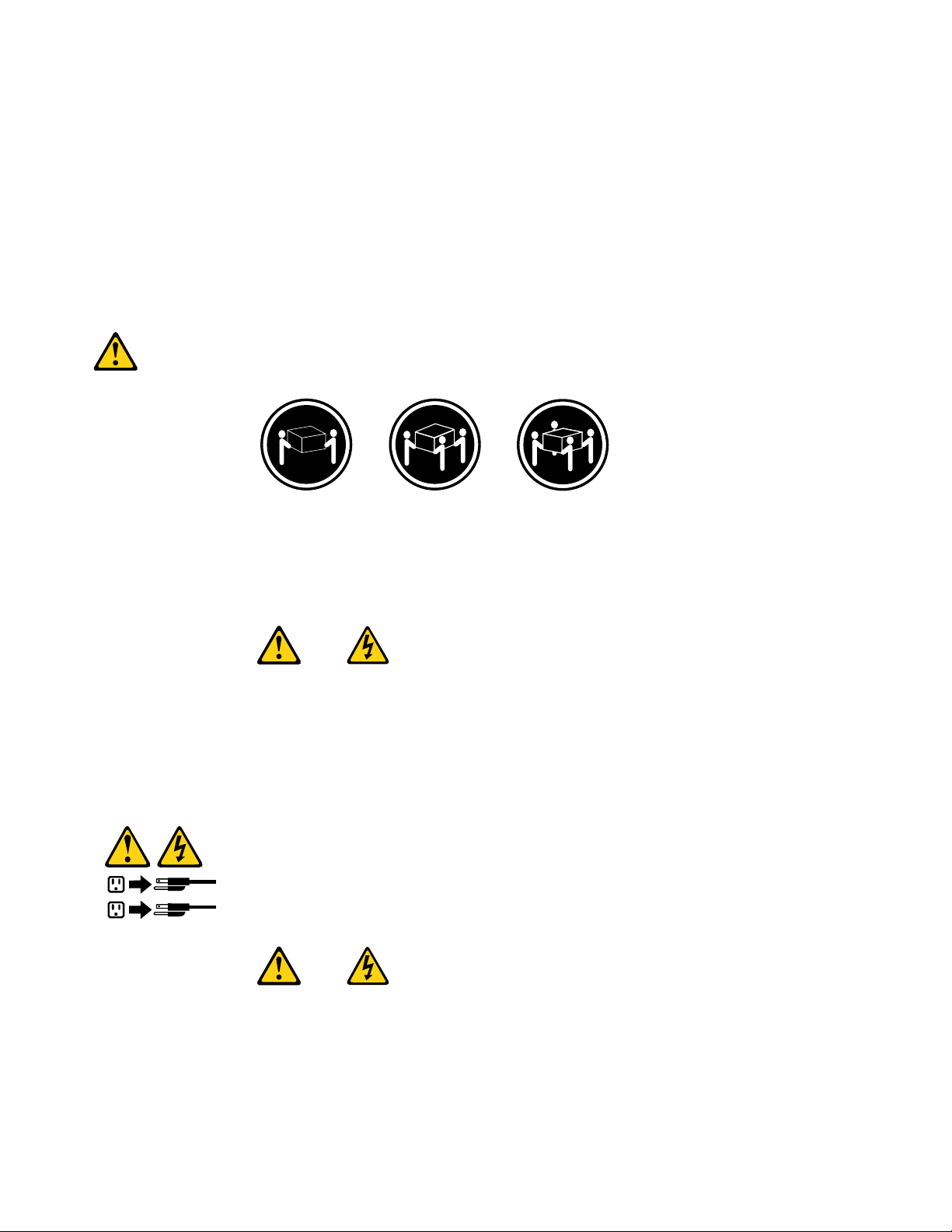
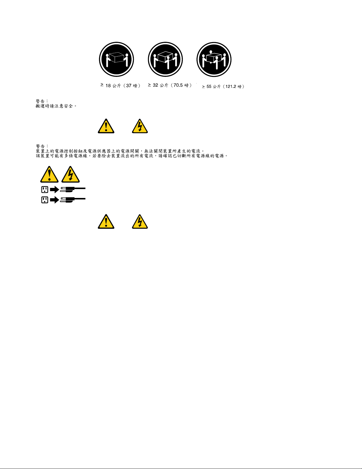
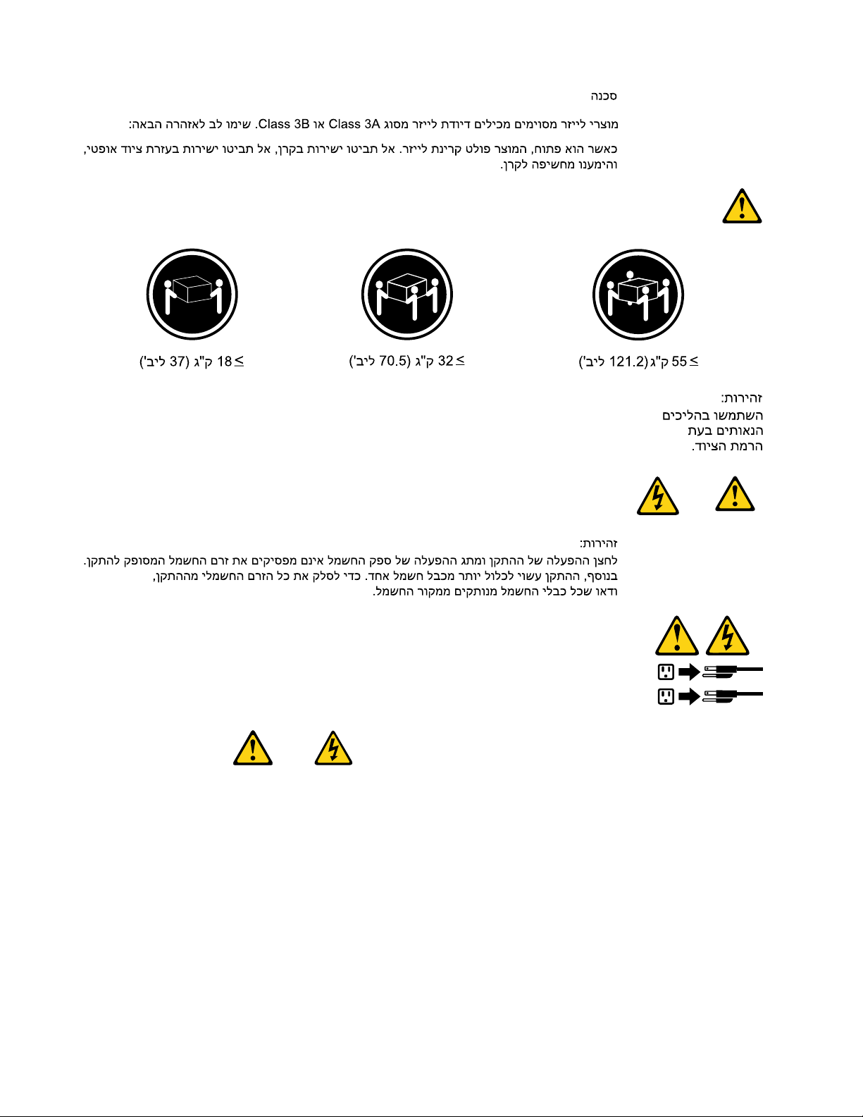
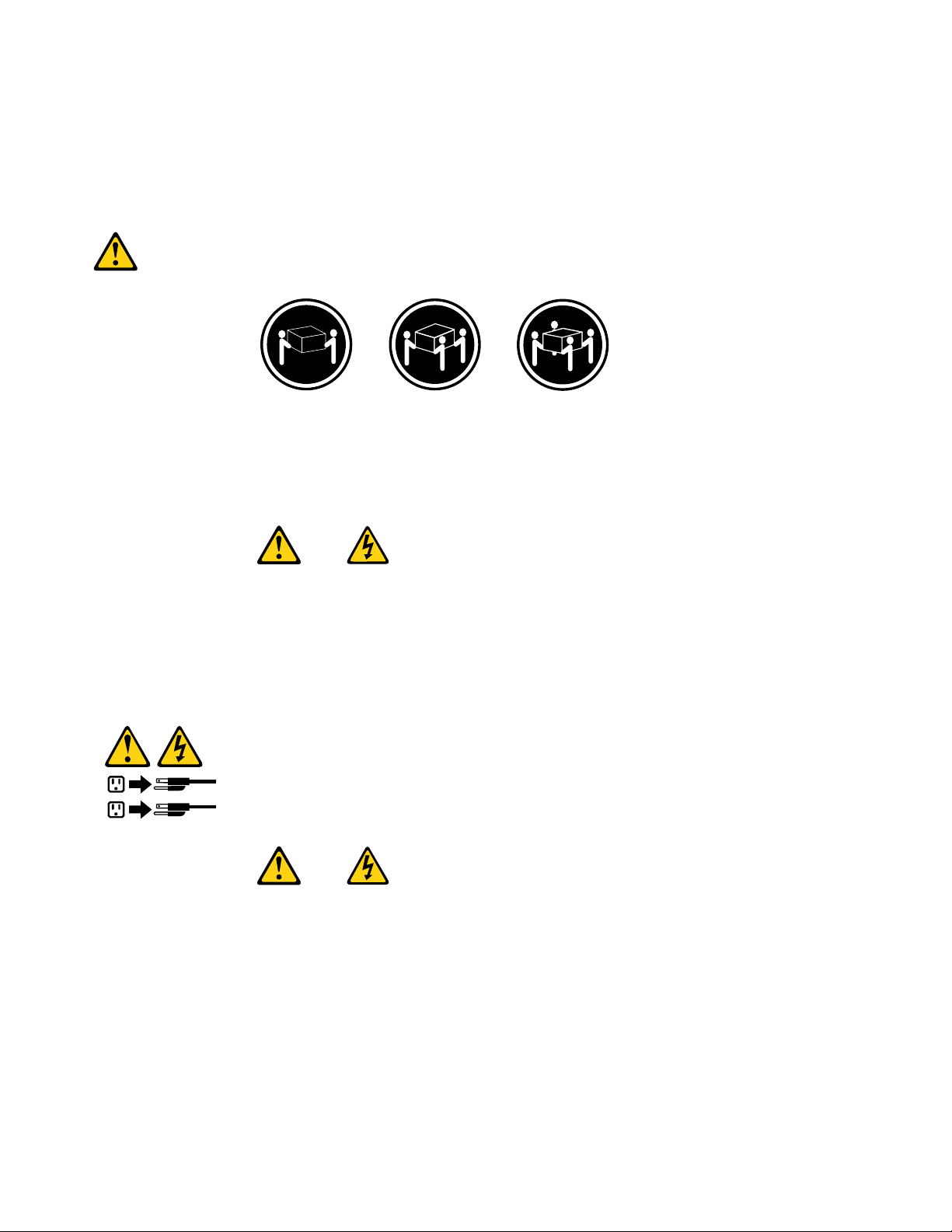
≥18kg(37lbs)≥32kg(70.5lbs)≥55kg(121.2lbs)
CAUTION:
Usesafepracticeswhenlifting.
CAUTION:
Thepowercontrolbuttononthedeviceandthepowerswitchonthepowersupplydonotturnoff
theelectricalcurrentsuppliedtothedevice.Thedevicealsomighthavemorethanonepower
cord.Toremoveallelectricalcurrentfromthedevice,ensurethatallpowercordsaredisconnected
fromthepowersource.
8ThinkCentreHardwareMaintenanceManual
Page 15
Chapter2.Safetyinformation9
Page 16
≥18kg(37lbs)≥32kg(70.5lbs)≥55kg(121.2lbs)
1
2
PERIGO
10ThinkCentreHardwareMaintenanceManual
Page 17
Acorrenteelétricaprovenientedecabosdealimentação,detelefoneedecomunicaçõeséperigosa.
Paraevitarriscodechoqueelétrico:
•Nãoconectenemdesconectenenhumcaboouexecuteinstalação,manutençãooureconguração
desteprodutoduranteumatempestadecomraios.
•Conectetodososcabosdealimentaçãoatomadaselétricascorretamenteinstaladaseaterradas.
•T odoequipamentoqueforconectadoaesteprodutodeveserconectadoatomadascorretamente
instaladas.
•Quandopossível,utilizeapenasumadasmãosparaconectaroudesconectarcabosdesinal.
•Nuncaliguenenhumequipamentoquandohouverevidênciadefogo,águaoudanosestruturais.
•Antesdeabrirtampasdedispositivos,desconectecabosdealimentação,sistemasdetelecomunicação,
redesemodemsconectados,amenosqueespecicadodemaneiradiferentenosprocedimentosde
instalaçãoeconguração.
•Conecteedesconecteoscabosconformedescritonatabelaapresentadaaseguiraoinstalar,moverou
abrirtampasdesteprodutooudedispositivosconectados.
ParaConectar:ParaDesconectar:
1.DESLIGUETudo.
2.Primeiramente,conectetodososcabosaos
dispositivos.
3.Conecteoscabosdesinalaosconectores.
4.Conecteoscabosdealimentaçãoàstomadas.
5.LIGUEosdispositivos.
1.DESLIGUETudo.
2.Primeiramente,removaoscabosdealimentaçãodas
tomadas.
3.Removaoscabosdesinaldosconectores.
4.Removatodososcabosdosdispositivos.
CUIDADO:
Aosubstituirabateriadelítio,utilizeapenasumabateriacomNúmerodePeça45C1566ouumtipo
debateriaequivalenterecomendadopeloSeoseusistemapossuiummódulocomumabateriade
lítio,substitua-oapenasporummódulodomesmotipoedomesmofabricante.Abateriacontémlítio
epodeexplodirsenãoforutilizada,manuseadaoudescartadademaneiracorreta.
Não:
•Jogueoucoloquenaágua
•Aqueçaamaisde100°C(212°F)
•Consertenemdesmonte
Descarteabateriaconformerequeridopelasleisouregulamentoslocais.
PRECAUCIÓN:
Quandoprodutosalaser(comounidadesdeCD-ROMs,unidadesdeDVD-ROM,dispositivosdebraótica
outransmissores)estivereminstalados,observeoseguinte:
Chapter2.Safetyinformation11
Page 18
•Nãoremovaastampas.Aremoçãodastampasdeumprodutoalaserpoderesultaremexposição
1
2
prejudicialàradiaçãodelaser.Nãoexistempeçasquepodemserconsertadasnointeriordodispositivo.
•Autilizaçãodecontrolesouajustesouaexecuçãodeprocedimentosdiferentesdosespecicadosaqui
poderesultaremexposiçãoprejudicialàradiação.
PERIGO
AlgunsprodutosalasercontêmdiododelaserintegradodaClasse3AoudaClasse3B.Observeoseguinte:
Radiaçãoalaserquandoaberto.Nãoolhediretamenteparaofeixeaolhonuoucominstrumentosópticose
eviteexposiçãodiretaaofeixe.
≥18kg(37lbs)≥32kg(70.5lbs)≥55kg(121.2lbs)
CUIDADO:
Utilizeprocedimentosdesegurançaparalevantarequipamentos.
CUIDADO:
Obotãodecontroledealimentaçãododispositivoeobotãoparaligar/desligardafontedealimentação
nãodesligamacorrenteelétricafornecidaaodispositivo.Odispositivotambémpodetermaisdeumcabo
dealimentação.Pararemovertodaacorrenteelétricadodispositivo,assegurequetodososcabosde
alimentaçãoestejamdesconectadosdafontedealimentação.
12ThinkCentreHardwareMaintenanceManual
Page 19
Chapter2.Safetyinformation13
Page 20
1
2
14ThinkCentreHardwareMaintenanceManual
Page 21
Chapter2.Safetyinformation15
Page 22
1
2
DANGER
Lecourantélectriqueprovenantdel'alimentation,dutéléphoneetdescâblesdetransmissionpeutprésenter
undanger.
Pourévitertoutrisquedechocélectrique:
•Nemanipulezaucuncâbleetn'effectuezaucuneopérationd'installation,d'entretienoudereconguration
deceproduitaucoursd'unorage.
•Brancheztouslescordonsd'alimentationsurunsocledeprisedecourantcorrectementcâbléetmisàla
terre.
•Branchezsurdessoclesdeprisedecourantcorrectementcâbléstoutéquipementconnectéàceproduit.
•Lorsquecelaestpossible,n'utilisezqu'uneseulemainpourconnecteroudéconnecterlescâbles
d'interface.
•Nemettezjamaisunéquipementsoustensionencasd'incendieoud'inondation,ouenprésencede
dommagesmatériels.
•Avantderetirerlescartersdel'unité,mettezcelle-cihorstensionetdéconnectezsescordons
d'alimentation,ainsiquelescâblesquilarelientauxréseaux,auxsystèmesdetélécommunicationetaux
modems(saufinstructioncontrairementionnéedanslesprocéduresd'installationetdeconguration).
•Lorsquevousinstallez,quevousdéplacez,ouquevousmanipulezleprésentproduitoudespériphériques
quiluisontraccordés,reportez-vousauxinstructionsci-dessouspourconnecteretdéconnecterles
différentscordons.
16ThinkCentreHardwareMaintenanceManual
Page 23
ConnexionDéconnexion
1.MettezlesunitésHORSTENSION.
2.Commencezparbranchertouslescordonssurles
unités.
3.Branchezlescâblesd'interfacesurdesconnecteurs.
4.Branchezlescordonsd'alimentationsurdesprises.
5.MettezlesunitésSOUSTENSION.
1.MettezlesunitésHORSTENSION.
2.Débranchezlescordonsd'alimentationdesprises.
3.Débranchezlescâblesd'interfacedesconnecteurs.
4.Débrancheztouslescâblesdesunités.
ATTENTION:
Remplacerlapileaulithiumusagéeparunepilederéférenceidentiqueexclusivement,(référence
45C1566),ousuivrelesinstructionsdufabricantquiendénitleséquivalences.Sivotresystèmeest
dotéd'unmodulecontenantunepileaulithium,vousdevezleremplaceruniquementparunmodule
identique,produitparlemêmefabricant.Lapilecontientdulithiumetpeutexploserencasde
mauvaiseutilisation,demauvaisemanipulationoudemiseaurebutinappropriée.
Nepas:
•lajeteràl'eau,
•l'exposeràdestempératuressupérieuresà100°C,
•chercheràlaréparerouàladémonter.
Nepasmettrelapileàlapoubelle.Pourlamiseaurebut,sereporteràlaréglementationenvigueur.
ATTENTION:
Sidesproduitsàlaser(telsquedesunitésdeCD-ROM,deDVD-ROM,desunitésàbresoptiques,ou
desémetteurs)sontinstallés,prenezconnaissancedesinformationssuivantes:
•Neretirezpaslecarter.Enouvrantl'unitédeCD-ROMoudeDVD-ROM,vousvousexposezau
rayonnementdangereuxdulaser.Aucunepiècedel'unitén'estréparable.
•Pourévitertoutrisqued'expositionaurayonlaser,respectezlesconsignesderéglageet
d'utilisationdescommandes,ainsiquelesprocéduresdécritesdansleprésentmanuel.
DANGER
Certainsproduitsàlasercontiennentunediodeàlaserintégréedeclasse3Aou3B.Prenez
connaissancedesinformationssuivantes:
Rayonnementlaserlorsquelecarterestouvert.Eviteztouteexpositiondirecteaurayonlaser.Evitez
deregarderxementlefaisceauoudel'observeràl'aided'instrumentsoptiques.
Chapter2.Safetyinformation17
Page 24
≥18kg(37lbs)≥32kg(70.5lbs)≥55kg(121.2lbs)
1
2
ATTENTION:
Soulevezlamachineavecprécaution.
ATTENTION:
L'interrupteurdecontrôled'alimentationdel'unitéetl'interrupteurdublocd'alimentationnecoupent
paslecourantélectriquealimentantl'unité.Enoutre,lesystèmepeutêtreéquipédeplusieurs
cordonsd'alimentation.Pourmettrel'unitéhorstension,vousdevezdéconnectertouslescordons
delasourced'alimentation.
VORSICHT
AnNetz-,Telefon-undDatenleitungenkönnengefährlicheSpannungenanliegen.
AusSicherheitsgründen:
•BeiGewitterandiesemGerätkeineKabelanschließenoderlösen.FernerkeineInstallations-,
Wartungs-oderRekongurationsarbeitendurchführen.
•GerätnuraneineSchutzkontaktsteckdosemitordnungsgemäßgeerdetemSchutzkontakt
anschließen.
•AlleangeschlossenenGeräteebenfallsanSchutzkontaktsteckdosenmitordnungsgemäß
geerdetemSchutzkontaktanschließen.
•DieSignalkabelnachMöglichkeiteinhändiganschließenoderlösen,umeinenStromschlagdurch
BerührenvonOberächenmitunterschiedlichemelektrischemPotenzialzuvermeiden.
•Geräteniemalseinschalten,wennHinweiseaufFeuer,WasseroderGebäudeschädenvorliegen.
18ThinkCentreHardwareMaintenanceManual
Page 25
•DieVerbindungzudenangeschlossenenNetzkabeln,T elekommunikationssystemen,Netzwerken
undModemsistvordemÖffnendesGehäuseszuunterbrechen,sofernindenInstallations-und
KongurationsprozedurenkeineanderslautendenAnweisungenenthaltensind.
•ZumInstallieren,TransportierenundÖffnenderAbdeckungendesComputersoderder
angeschlossenenEinheitendieKabelgemäßderfolgendenTabelleanschließenundabziehen.
ZumAnschließenderKabelgehenSiewiefolgtvorZumAbziehenderKabelgehenSiewiefolgtvor
1.SchaltenSiealleEinheitenAUS.
2.SchließenSieerstalleKabelandieEinheitenan.
3.SchließenSiedieSignalkabelandieBuchsenan.
4.SchließenSiedieNetzkabelandieSteckdosean.
5.SchaltenSiedieEinheitEIN.
1.SchaltenSiealleEinheitenAUS.
2.ZiehenSiezuerstalleNetzkabelausden
Netzsteckdosen.
3.ZiehenSiedieSignalkabelausdenBuchsen.
4.ZiehenSiealleKabelvondenEinheitenab.
CAUTION:
EineverbrauchteLithiumbatterienurdurcheineBatteriemitderTeilenummer45C1566odereine
gleichwertige,vomHerstellerempfohleneBatterieersetzen.EnthältdasSystemeinModulmiteiner
Lithiumbatterie,diesesnurdurcheinModuldesselbenTypsundvondemselbenHerstellerersetzen.
DieBatterieenthältLithiumundkannbeiunsachgemäßerVerwendung,HandhabungoderEntsorgung
explodieren.
DieBatterienicht:
•mitWasserinBerührungbringen.
•über100Cerhitzen.
•reparierenoderzerlegen.
DieörtlichenBestimmungenfürdieEntsorgungvonSondermüllbeachten.
ACHTUNG:
BeiderInstallationvonLasergeräten(wieCD-ROM-Laufwerken,DVD-aufwerken,Einheitenmit
LichtwellenleitertechnikoderSendern)Folgendesbeachten:
•DieAbdeckungennichtentfernen.DurchEntfernenderAbdeckungendesLasergerätskönnen
gefährlicheLaserstrahlungenfreigesetztwerden.DasGerätenthältkeinezuwartendenTeile.
•WerdenSteuerelemente,EinstellungenoderDurchführungenvonProzedurenandersalshier
angegebenverwendet,kanngefährlicheLaserstrahlungauftreten.
VORSICHT
EinigeLasergeräteenthalteneineLaserdiodederKlasse3Aoder3B.BeachtenSieFolgendes:
Chapter2.Safetyinformation19
Page 26
LaserstrahlungbeigeöffneterVerkleidung.NichtindenStrahlblicken.KeineLupenoderSpiegel
1
2
verwenden.Strahlungsbereichmeiden.
≥18kg(37lbs)≥32kg(70.5lbs)≥55kg(121.2lbs)
ACHTUNG:
ArbeitsschutzrichtlinienbeimAnhebenderMaschinebeachten.
ACHTUNG:
MitdemNetzschalteranderEinheitundamNetzteilwirddieStromversorgungfürdieEinheit
nichtunterbrochen.DieEinheitkannauchmitmehrerenNetzkabelnausgestattetsein.Umdie
StromversorgungfürdieEinheitvollständigzuunterbrechen,müssenallezumGerätführenden
NetzkabelvomNetzgetrenntwerden.
20ThinkCentreHardwareMaintenanceManual
Page 27
Chapter2.Safetyinformation21
Page 28
1
2
PERICOLO
Lacorrenteelettricaprovenientedaicavidialimentazione,deltelefonoedicomunicazionepuòessere
pericolosa.
Perevitareilrischiodiscosseelettriche:
•Noncollegareoscollegarequalsiasicavooppureeffettuarel'installazione,lamanutenzioneola
ricongurazionedelprodottoduranteuntemporale.
•Collegaretuttiilielettriciaunapresadialimentazionecorrettamentecablataedotatadimessaa
terra.
•Collegareallepreseelettricheappropriatetutteleapparecchiaturecheverrannoutilizzateper
questoprodotto.
22ThinkCentreHardwareMaintenanceManual
Page 29
•Sepossibile,utilizzaresolounamanopercollegareoscollegareicavidisegnale.
•Nonaccendereassolutamenteapparecchiatureinpresenzadiincendi,perdited'acquaodanno
strutturale.
•Scollegareicavidialimentazione,isistemiditelecomunicazione,leretieilmodemprimadi
aprireicoperchideldispositivo,salvoistruzionicontrarierelativealleprocedurediinstallazionee
congurazione.
•Collegareescollegareicavicomedescrittonellaseguentetabellaquandovengonoeffettuate
operazionidiinstallazione,spostamentooaperturadeicoperchidiquestoprodottoodelleunità
collegate.
PercollegarsiPerscollegarsi
1.SPEGNEREleapparecchiature.
2.Innanzitutto,collegaretuttiicavialleunità.
3.Collegareicavidisegnaleaiconnettori.
4.Collegareicavidialimentazioneallapresa.
5.Accenderel'unità.
1.SPEGNEREleapparecchiature.
2.Innanzitutto,rimuovereicavidialimentazionedalla
presa.
3.Rimuovereicavidisegnaledaiconnettori.
4.Rimuoveretuttiicavidalleunità.
ATTENZIONE:
Quandosisostituiscelabatteriaallitio,utilizzaresoloilNumeroparte45C1566ountipodibatteria
equivalenteconsigliatodalproduttore.Sesulsistemaèpresenteunmodulochecontieneunabatteria
allitio,sostituirlosoloconuntipodimodulodellostessotipodellastessacasadiproduzione.La
batteriacontienelitioepuòesplodereseusata,maneggiataosmaltitainmodononcorretto.
Non:
•Gettareoimmergerelabatterianell'acqua
•Riscaldarlaadunatemperaturasuperioreai100gradiC(212gradiF)
•Smontarla,ricaricarlaotentarediripararla
Lebatterieusatevannosmaltiteinaccordoallanormativainvigore(DPR915/82esuccessive
disposizioniedisposizionilocali).
ATTENZIONE:
Quandovengonoinstallatiprodottilaser(qualiCD-ROM,unitàDVD-ROM,unitàabreotticheo
trasmittenti),tenerpresentequantosegue:
•Nonrimuovereglisportelli.L'aperturadiun'unitàlaserpuòdeterminarel'esposizionearadiazioni
laserpericolose.All'internodell'unitànonvisonopartisucuieffettuarel'assistenzatecnica.
•L'utilizzodicontrolli,regolazioniol'esecuzionediprocedurenondescrittinelpresentemanuale
possonoprovocarel'esposizionearadiazionipericolose.
Chapter2.Safetyinformation23
Page 30
PERICOLO
1
2
AlcuneunitàlasercontengonoundiodolaserdiClasse3AoClasse3B.Tenerpresentequantosegue:
Aprendol'unitàvengonoemesseradiazionilaser.Nonssareilfascio,nonguardarlodirettamente
construmentiotticiedevitarel'esposizionealfascio.
≥18kg(37lbs)≥32kg(70.5lbs)≥55kg(121.2lbs)
ATTENZIONE:
Prestareattenzionenelsollevarel'apparecchiatura.
ATTENZIONE:
Ilpulsantedicontrollodell'alimentazionepresentesull'unitàel'interruttoredell'alimentatorenon
disattivanol'alimentazionecorrentefornitaall'unità.E'possibilechel'unitàdispongadipiùcavidi
alimentazione.Perdisattivarel'alimentazionedall'unità,accertarsichetuttiicavidialimentazione
sianoscollegatidallafontedialimentazione.
24ThinkCentreHardwareMaintenanceManual
Page 31

Chapter2.Safetyinformation25
Page 32

1
2
PELIGRO
Lacorrienteeléctricaprocedentedecablesdealimentación,teléfonosycablesdecomunicaciónpuede
serpeligrosa.
Paraevitarelriesgodedescargaeléctrica:
•Noconectenidesconecteloscablesnirealiceningunatareadeinstalación,mantenimientoo
reconguracióndeesteproductoduranteunatormentaeléctrica.
•Conectetodosloscablesdealimentaciónatomasdecorrientedebidamentecableadasy
conectadasatierra.
•Cualquierequipoqueseconecteaesteproductotambiéndebeconectarseatomasdecorriente
debidamentecableadas.
•Siemprequeseaposible,utiliceunasolamanoparaconectarodesconectarloscablesdeseñal.
•Noenciendanuncaunequipocuandohayseñalesdefuego,aguaodañosestructurales.
26ThinkCentreHardwareMaintenanceManual
Page 33

•Desconecteloscablesdealimentación,lossistemasdetelecomunicaciones,lasredesylos
módemsconectadosantesdeabrirlascubiertasdelosdispositivos,amenosqueseindiquelo
contrarioenlosprocedimientosdeinstalaciónyconguración.
•Conecteydesconecteloscables,comosedescribeenlatablasiguiente,cuandoinstale,muevao
abralascubiertasdeesteproductoodelosdispositivosconectados.
ParaconectarParadesconectar
1.APÁGUELOtodo.
2.Enprimerlugar,conectetodosloscablesalos
dispositivos.
3.Conecteloscablesdeseñalalosconectores.
4.Enchufeloscablesdealimentaciónalastomasde
corriente.
5.Enciendaeldispositivo.
1.APÁGUELOtodo.
2.Enprimerlugar,desenchufeloscablesdealimentación
delastomasdecorriente.
3.Desconecteloscablesdeseñaldelosconectores.
4.Desconectetodosloscablesdelosdispositivos.
PRECAUCIÓN:
Cuandosustituyaunabateríadelitio,utilicesolamenteunabateríanúmerodepieza45C1566uotra
detipoequivalenterecomendadaporelfabricante.Sisusistemadisponedeunmóduloquecontiene
unabateríadelitio,reemplácelosóloconelmismotipodemódulo,delmismofabricante.Labatería
contienelitioypuedeexplotarsinoseutiliza,manipulaodesechacorrectamente.
Nodebe:
•Arrojarlaalaguaosumergirlaenella
•Exponerlaatemperaturassuperioresa100°C(212°F)
•Repararlaodesmontarla
Deshágasedelabateríasegúnespeciquenlasleyesonormaslocales.
PRECAUCIÓN:
Cuandohayaproductosláser(comounidadesdeCD-ROM,unidadesdeDVD,dispositivosdebra
ópticaotransmisores)instalados,tengaencuentalosiguiente:
•Noquitelascubiertas.Siquitalascubiertasdelproductoláser,podríaquedarexpuestoaradiación
láserpeligrosa.Dentrodeldispositivonoexisteningunapiezaquerequieraserviciotécnico.
•Siusacontrolesoajustesorealizaprocedimientosquenoseanlosespecicadosaquí,podría
exponersearadiacionespeligrosas.
PELIGRO
Chapter2.Safetyinformation27
Page 34

Algunosproductoslásertienenincorporadoundiodoláserdeclase3Aoclase3B.Tengaencuentalo
1
2
siguiente:
Cuandoseabre,quedaexpuestoaradiaciónláser.Nomiredirectamentealrayoláser,nisiquieracon
instrumentosópticos,yeviteexponersedirectamentealrayoláser.
≥18kg(37lbs)≥32kg(70.5lbs)≥55kg(121.2lbs)
PRECAUCIÓN:
Adopteprocedimientossegurosallevantarelequipo.
PRECAUCIÓN:
Elbotóndecontroldealimentacióndeldispositivoyelinterruptordealimentacióndelafuentede
alimentaciónnodesconectanlacorrienteeléctricasuministradaaldispositivo.Además,eldispositivo
podríatenermásdeuncabledealimentación.Parasuprimirtodalacorrienteeléctricadeldispositivo,
asegúresedequetodosloscablesdealimentaciónesténdesconectadosdelatomadecorriente.
28ThinkCentreHardwareMaintenanceManual
Page 35

Chapter3.Generalinformation
Thischapterprovidesgeneralinformationthatappliestoallthemachinetypessupportedbythismanual.
OnlineBooksfolder
TheOnlineBooksfolderpreinstalledonyourcomputercontainstheThinkCentreUserGuide,whichprovides
informationaboutyourcomputertohelpyousetup,use,andmaintainyourcomputer.Itrequiresno
Internetaccesstoviewthepublication.
Toviewthepublication,clickStart®AllPrograms®OnlineBooks®OnlineBooks,thendouble-click
theappropriatepublicationforyourcomputer.ThepublicationisalsoavailableontheLenovoSupportWeb
siteat:
http://www.lenovo.com/support
Notes:
1.ThepublicationisinPortableDocumentFormat(PDF).Toviewthepublication,youneedtohavethe
AdobeReaderprogrampreinstalledonyourcomputer.IftheAdobeReaderprogramhasnotbeen
installedonyourcomputer,amessagewillbedisplayedwhenyouattempttoviewthePDFleandyou
willbeguidedthroughtheAdobeReaderinstallation.
2.ThepublicationisavailableinotherlanguagesontheLenovoSupportWebsiteat:
http://www.lenovo.com/support
3.IfyouwanttoinstalladifferentlanguageversionoftheAdobeReaderprogramratherthantheversion
preinstalledonyourcomputer,downloadthedesiredlanguageversionfromtheAdobeWebsiteat:
http://www.adobe.com
LenovoThinkVantageTools
TheLenovoThinkVantage®Toolsprogramguidesyoutoahostofinformationsourcesandprovideseasy
accesstovarioustoolstohelpyouworkmoreeasilyandsecurely.
Note:TheLenovoThinkVantageToolsprogramisonlyavailableoncomputerswiththeMicrosoft®
Windows®7operatingsystemfromLenovo.
ToaccesstheLenovoThinkVantageT oolsprogram,clickStart®AllPrograms®LenovoThinkVantage
Tools.
ThinkVantageProductivityCenter
TheThinkVantageProductivityCenterprogramcontainsinformationsourcesandtoolsdesignedtomake
computingeasyandsecure.Itprovideseasyaccesstovarioustechnologies,suchas:
•ClientSecuritySolutionorPasswordManager
•ProductRecovery
•PowerManager
•RescueandRecovery®
•SystemUpdate
Note:TheThinkVantageProductivityCenterprogramisonlyavailableoncomputerspreinstalledwiththe
MicrosoftWindowsVista®orWindowsXPoperatingsystemfromLenovo.
©CopyrightLenovo2009,2011
29
Page 36

ToaccesstheThinkVantageProductivityCenterprogram,clickStart®AllPrograms®ThinkVantage
®ProductivityCenter.
LenovoWelcome
Note:TheLenovoWelcomeprogramisonlyavailableoncomputerspreinstalledwithWindows7or
WindowsVistafromLenovo.
TheLenovoWelcomeprogramintroducessomeinnovativebuilt-infeaturesofLenovotoyouandguidesyou
throughsomeimportantsetuptaskstohelpyoumakethemostofyourcomputer.
AccessHelp
TheAccessHelpinformationsystemprovidesinformationaboutgettingstarted,doingbasictasks,
customizingsettingsforyourpersonalpreference,protectingdata,expandingandupgrading,and
troubleshooting.
•T oopentheAccessHelpinformationsystemonWindows7,clickStart®HelpandSupport®Lenovo
AccessHelp.
•T oopentheAccessHelpinformationsystemonWindowsVistaorWindowsXP,clickStart®All
Programs®ThinkVantage®AccessHelp.
AfteryouhaveopenedtheAccessHelpinformationsystem,usetheleftpaneltomakeaselectionfromthe
ContentstabortheIndextab,orusetheSearchtabtondaparticularwordorphrase.
Additionalinformationresources
IfyouhaveInternetaccess,themostup-to-dateinformationforyourcomputerisavailable
at:http://www.lenovo.com/support
Youcanndthefollowinginformation:
•CRUinstallationorreplacementinstructions
•Downloadsanddrivers
•Publications
•Partsinformation
•T roubleshootinginformation
•Linkstootherusefulsourcesofinformation
Specications
Thissectionliststhephysicalspecicationsforyourcomputer.
30ThinkCentreHardwareMaintenanceManual
Page 37

Dimensions
Width:175mm(6.9inches)
Height:412mm(16.2inches)
Depth:442mm(17.4inches)
Weight
Maximumcongurationasshipped:11.0kg(24.3lbs)
Environment
•Airtemperature:
Operating:10°to35°C(50°to95°F)
Non-operating:-40°to60°C(-40°to140°F)(withpackage)
Non-operating:-10°to60°C(14°to140°F)(withoutpackage)
•Humidity:
Operating:20%to80%(10%perhour,noncondensing)
Non-operating:20%to90%(10%perhour,noncondensing)
•Altitude:
Operating:-50to10000ft(-15.2to3048m)
Non-operating:-50to35000ft(-15.2to10668m)
Electricalinput
•Inputvoltage:
–Lowrange:
Minimum:100Vac
Maximum:127Vac
Inputfrequencyrange:50to60Hz
Voltage-selectionswitchsetting:115Vac
–Highrange:
Minimum:200Vac
Maximum:240Vac
Inputfrequencyrange:50to60Hz
Voltage-selectionswitchsetting:230Vac
Chapter3.Generalinformation31
Page 38

32ThinkCentreHardwareMaintenanceManual
Page 39

Chapter4.Generalcheckout
Attention
Thedrivesinthecomputeryouareservicingmighthavebeenrearrangedorthedrivestartupsequence
changed.Beextremelycarefulduringwriteoperationssuchascopying,saving,orformatting.Dataor
programscanbeoverwrittenifyouselectanincorrectdrive.
Generalerrormessagesappearifaproblemorconictisfoundbyanapplicationprogram,theoperating
system,orboth.Foranexplanationofthesemessages,refertotheinformationsuppliedwiththatsoftware
package.
BeforereplacinganyFRUs,ensurethatthelatestlevelofBIOSisinstalledonthesystem.Adown-levelBIOS
mightcausefalseerrorsandunnecessaryreplacementofthesystemboard.Formoreinformationonhowto
determineandobtainthelatestlevelBIOS,see“BIOSlevels”onpage203
Usethefollowingproceduretohelpdeterminethecauseoftheproblem:
1.Power-offthecomputerandallexternaldevices.
2.Checkallcablesandpowercords.
3.Setalldisplaycontrolstothemiddleposition.
4.Power-onallexternaldevices.
5.Power-onthecomputer.
•Lookfordisplayederrorcodes
•Listenforbeepcodes
•Lookforreadableinstructionsoramainmenuonthedisplay.
Ifyoudidnotreceivethecorrectresponse,proceedtostep6onpage33
Ifyoudoreceivethecorrectresponse,proceedtostep7onpage33.
6.Lookatthefollowingconditionsandfollowtheinstructions:
.
.
•IfyouhearbeepcodesduringPOST,goto“Beepsymptoms”onpage61
•IfthecomputerdisplaysaPOSTerror,goto“POSTerrorcodes”onpage62.
•Ifthecomputerhangsandnoerrorisdisplayed,continueatstep7onpage33.
7.RuntheDiagnosticprograms.SeeChapter5“Diagnostics”onpage35.
•Ifyoureceiveanerror,replacethepartthatthediagnosticprogramcallsoutorgoto“Diagnostic
errorcodes”onpage43.
•Iftheteststopsandyoucannotcontinue,replacethelastdevicetested.
.
Problemdeterminationtips
Duetothevarietyofhardwareandsoftwarecombinationsthatcanbeencountered,usethefollowing
informationtoassistyouinproblemdetermination.Ifpossible,havethisinformationavailablewhen
requestingassistancefromServiceSupportandEngineeringfunctions.
•Machinetypeandmodel
•Processororharddiskupgrades
•Failuresymptom
–Dodiagnosticsindicateafailure?
–What,when,where,single,ormultiplesystems?
–Isthefailurerepeatable?
©CopyrightLenovo2009,2011
33
Page 40

–Hasthiscongurationeverworked?
–Ifithasbeenworking,whatchangesweremadepriortoitfailing?
–Isthistheoriginalreportedfailure?
•Diagnosticsversion
–T ypeandversionlevel
•Hardwareconguration
–Print(printscreen)congurationcurrentlyinuse
–BIOSlevel
•Operatingsystemsoftware
–T ypeandversionlevel
Notes:Toeliminateconfusion,identicalsystemsareconsideredidenticalonlyifthey:
1.Aretheexactmachinetypeandmodels
2.HavethesameBIOSlevel
3.Havethesameadapters/attachmentsinthesamelocations
4.Havethesameaddressjumpers/terminators/cabling
5.Havethesamesoftwareversionsandlevels
6.HavethesameDiagnosticDiskettes(version)
7.Havethesamecongurationoptionssetinthesystem
8.Havethesamesetupfortheoperatingsystemcontrolles
Comparingthecongurationandsoftwaresetupbetween“workingandnon-working”systemswilloften
leadtoproblemresolution.
34ThinkCentreHardwareMaintenanceManual
Page 41

Chapter5.Diagnostics
Diagnosticprogramsareusedtotesthardwarecomponentsofyourcomputerandreport
operating-system-controlledsettingsthatcancausehardwarefailures.Therearetwoprogramspreinstalled
onyourcomputertohelpyoudiagnosecomputerproblems:
•LenovoThinkVantageToolboxorLenovoSystemToolbox,dependingonyouroperatingsystem(used
whenyouarerunningtheWindowsoperatingsystem)
•PC-DoctorforRescueandRecovery(usedwhenyourWindowsoperatingsystemdoesnotstart)
Notes:
1.YoucanalsodownloadthePC-DoctorforDOSdiagnosticprogramfrom:
http://www.lenovo.com/support.See“PC-DoctorforDOS”onpage36fordetailedinformation.
2.Ifyouareunabletoisolateandrepairtheproblemyourselfafterrunningthediagnosticprograms,
saveandprinttheloglescreatedbythediagnosticprograms.Y ouwillneedthelogleswhenyou
speaktoaLenovotechnicalsupportrepresentative.
LenovoThinkVantageToolbox
Note:TheLenovoThinkVantageToolboxprogramisonlyavailableoncomputerspreinstalledwithWindows
7fromLenovo.
TheLenovoThinkVantageToolboxprogramhelpsyoumaintainyourcomputer,improvecomputingsecurity,
diagnosecomputerproblems,getfamiliarwiththeinnovativetechnologiesprovidedbyLenovo,andget
moreinformationaboutyourcomputer.YoucanusetheDiagnosticsfeatureoftheLenovoThinkVantage
Toolboxprogramtotestdevices,diagnoseproblems,createbootablediagnosticmedia,updatesystem
drivers,andreviewsysteminformation.
TodiagnosethecomputerproblemsbyusingtheLenovoThinkVantageT oolboxprogram,clickStart®All
Programs®LenovoThinkVantageTools®SystemHealthandDiagnostics®Diagnostics.Follow
theinstructionsonthescreen.
ForadditionalinformationaboutrunningtheLenovoThinkVantageToolboxprogram,refertotheLenovo
ThinkVantageT oolboxhelpsystem.
LenovoSystemToolbox
Note:TheLenovoSystemT oolboxprogramisonlyavailableoncomputerspreinstalledwithWindowsVista
orWindowsXPfromLenovo.
TheLenovoSystemT oolboxprogramisadiagnosticprogramthatworksthroughtheWindowsoperating
systemandenablesyoutoviewsymptomsandsolutionsforcomputerproblems,accesstheLenovo
troubleshootingcenter,updatesystemdrivers,andreviewsysteminformation.
ToruntheLenovoSystemT oolboxprogram,clickStart®AllPrograms®LenovoServices®Lenovo
SystemT oolbox.Followtheinstructionsonthescreen.ForadditionalinformationaboutrunningtheLenovo
SystemT oolboxprogram,refertotheLenovoSystemToolboxhelpsystem.
TheLenovoSystemToolboxprogramalsohasproblemdeterminationaidsthatdeterminesoftwareand
usageproblems.
©CopyrightLenovo2009,2011
35
Page 42

PC-DoctorforRescueandRecovery
ThePC-DoctorforRescueandRecoverydiagnosticprogramispartoftheRescueandRecoveryworkspace
oneachLenovocomputer.UsethePC-DoctorforRescueandRecoveryprogramifyouareunableto
starttheWindowsoperatingsystem.
TorunthePC-DoctorforRescueandRecoveryprogramfromtheRescueandRecoveryworkspace,do
thefollowing:
1.Turnoffthecomputer.
2.RepeatedlypressandreleasetheF11keywhenturningonthecomputer.Whenyouhearbeepsorseea
logoscreen,stoppressingtheF11key.TheRescueandRecoveryworkspaceopensafterashortdelay.
3.FromtheRescueandRecoveryworkspace,selectLaunchadvancedRescueandRecovery®
Diagnosehardware.ThePC-DoctorforRescueandRecoverydiagnosticprogramopens.
4.Selectthediagnostictestyouwanttorun.Then,followtheinstructionsonthescreen.
ForadditionalinformationaboutrunningthePC-DoctorforRescueandRecoveryprogram,refertothe
PC-DoctorforRescueandRecoveryhelpsystem.
PC-DoctorforDOS
YoucanalsodownloadthelatestversionofthePC-DoctorforDOSdiagnosticprogramfrom
http://www.lenovo.com/support.ThePC-DoctorforDOSdiagnosticprogramrunsindependentlyofthe
Windowsoperatingsystem.UsethePC-DoctorforDOSdiagnosticprogramifyouareunabletostartthe
Windowsoperatingsystemorifthetwodiagnosticprogramspreinstalledonyourcomputerhavenot
beensuccessfulinisolatingapossibleproblem.Y oucanrunthePC-DoctorforDOSdiagnosticprogram
fromadiagnosticdiscthatyoucreated.
Creatingadiagnosticdisc
Thissectionprovidesinstructionsonhowtocreateadiagnosticdisc.
Tocreateadiagnosticdisc,dothefollowing:
1.Downloadaself-startingbootableCD/DVDimage(knownasanISOimage)ofthediagnosticprogram
from:
http://www.lenovo.com/support
2.UseanyCD/DVDburningsoftwaretocreateadiagnosticdiscwiththeISOimage.
Runningthediagnosticprogramfromadiagnosticdisc
Thissectionprovidesinstructionsonhowtorunthediagnosticprogramfromadiagnosticdiscthatyou
created.
Torunthediagnosticprogramfromadiagnosticdiscthatyoucreated,dothefollowing:
1.Makesuretheopticaldriveyouwanttouseissetastherstbootdeviceinthestartupdevicesequence.
See“Selectingastartupdevice”onpage41.
2.Makesurethecomputeristurnedonandtheninsertthediscintotheopticaldrive.Thediagnostic
programopens.
Note:Youcaninsertthediscintotheopticaldrivewhenyouaresettingthestartupdevicesequence.
However,ifyouinsertthediscintotheopticaldrivewhenyouhavealreadyenteredtheoperating
system,youneedtorestartthecomputertoaccessthediagnosticprogram.
36ThinkCentreHardwareMaintenanceManual
Page 43

3.Followtheinstructionsonthescreentoselectthediagnostictestyouwanttorun.
Note:Foradditionalhelp,presstheF1key.
4.Removethediagnosticdiscfromtheopticaldrivewhenyoucompletethediagnosticprocess.
Navigatingthroughthediagnosticsprograms
Usethecursormovementkeystonavigatewithinthemenus.
•TheEnterkeyisusedtoselectamenuitem.
•TheEsckeyisusedtobackuptothepreviousmenu.
•ForonlinehelpselectF1.
Runningtests
Therearefourwaystorunthediagnostictests.
•Usingthecursormovementkeys,highlightRunNormalTestorRunQuickT estfromtheDiagnostics
menuandthenpressEnter.Thisautomaticallyrunsapre-denedgroupoftestsfromeachtestcategory.
RunNormalT estrunsamoreextensivesetofteststhandoesRunQuickT estandtakeslongerto
complete.
•PressF5toautomaticallyrunallselectedtestsinallcategories.
•Fromwithinatestcategory,pressCtrl-Entertoautomaticallyrunonlytheselectedtestsinthatcategory.
•Usingthecursormovementkeys,highlightasingletestwithinatestcategory,andthenpressEnter.
Thisrunsonlythattest.
PressEscatanytimetostopthetestingprocess.
Testresults(N/A,PASSED,FAILED,ABORTED)aredisplayedintheeldbesidethetestdescriptionandin
thetestlog.See“Viewingthetestlog”onpage38.
Toselectoneormoretests,usethefollowingprocedure.
1.Openthecorrespondingtestcategory.
2.Usingthecursormovementkeys,highlightthedesiredtest.
3.Pressthespacebar.Aselectedtestismarkedby>>.Pressingthespacebaragainde-selectsatest
andremovesthe>>.
4.Repeatsteps2and3abovetoselectalldesiredtests.
Testresults
Diagnosticstestresultsproducethefollowingerrorcodeformat:
FunctionCode
•FunctionCode:
RepresentsthefeatureorfunctionwithinthePC.
•FailureType:
Representsthetypeoferrorencountered.
•DeviceID:
Containsthecomponent'sunit-IDwhichcorrespondstoeitheraxeddiskdrive,removablemediadrive,
serialorparallelport,processor,specicRIMM,oradeviceonthePCIbus.
FailureTypeDeviceIDDate
ChkDigits
Text
Chapter5.Diagnostics37
Page 44

•Date:
Containsthedatewhenthediagnostictestwasrun.ThedateisretrievedfromCMOSanddisplayed
usingtheYYYYMMDDformat.
•ChkDigits:
Containsa2-digitcheck-digitvaluetoensurethefollowing:
–Diagnosticswererunonthespecieddate.
–Diagnosticswererunonthespeciedcomputer.
–Thediagnosticerrorcodeisrecordedcorrectly.
•T ext:
Descriptionoftheerror.
Note:See“Diagnosticerrorcodes”onpage43forerrorcodelistings.
QuickandFullerase-harddrive
Thediagnosticsprogramofferstwoharddriveformatutilities:
•QuickEraseHardDrive
•FullEraseHardDrive
TheQuickEraseHardDriveprovidesaDOSutilitythatperformsthefollowing:
•DestroystheMasterBootRecord(MBR)ontheharddrive.
•DestroysallcopiesoftheFATTableonallpartitions(boththemasterandbackup).
•Destroysthepartitiontable.
•Providesmessagesthatwarntheuserthatthisisanon-recoverableprocess.
TheFullEraseHardDriveprovidesaDOSutilitythatperformsthefollowing:
•PerformsallthestepsinQuickErase.
•ProvidesaDOSutilitythatwritesrandomdatatoallsectorsoftheharddrive.
•Providesanestimateoftimetocompletionalongwithavisualrepresentationofcompletionstatus.
•Providesmessagesthatwarntheuseraboutnon-recoverableprocess.
Important:MakesurethatalldataisbackedupbeforeusingtheQuickorFullErasefunctions.
ToselecttheQuickEraseorFullEraseHardDriveutility,usethefollowingprocedure:
1.SelecttheUTILITYoptiononthetoolbarandpressEnter.
2.SelecteithertheQUICKERASEorFULLERASEHARDDISKoptionandfollowtheinstructions.
Viewingthetestlog
Errorsreportedbythediagnostictestwillbedisplayedbytheprogramasafailedtest.
Toviewdetailsofafailureortoviewalistoftestresults,usethefollowingprocedurefromanytestcategory
screen:
1.PressF3toactivatethelogle.
2.PressF3againtosavetheletodisketteorpressF2toprintthele.
38ThinkCentreHardwareMaintenanceManual
Page 45

Chapter6.UsingtheSetupUtilityprogram
YoucanusetheSetupUtilityprogramtoviewandchangethecongurationsettingsofyourcomputer,
regardlessofwhichoperatingsystemyouareusing.However,theoperatingsystemsettingsmightoverride
anysimilarsettingsintheSetupUtilityprogram.
ThischapterprovidesinformationaboutthefollowingtopicstohelpyouusetheSetupUtilityprogram:
•“StartingtheSetupUtilityprogram”onpage39
•“Viewingorchangingsettings”onpage39
•“Usingpasswords”onpage39
•“Enablingordisablingadevice”onpage40
•“Selectingastartupdevice”onpage41
•“ExitingtheSetupUtilityprogram”onpage42
StartingtheSetupUtilityprogram
ThissectionprovidesinstructionsonhowtostarttheSetupUtilityprogram.
TostarttheSetupUtilityprogram,dothefollowing:
1.Makesureyourcomputeristurnedoff.
2.RepeatedlypressandreleasetheF1keywhenturningonthecomputer.Whenyouhearmultiplebeeps
orseealogoscreen,releasetheF1key.TheSetupUtilityprogramopens.
Note:Ifapasswordhasbeenset,theSetupUtilityprogrammenuwillnotbedisplayeduntilyoutype
thecorrectpassword.Formoreinformation,see“Usingpasswords”onpage39.
Viewingorchangingsettings
TheSetupUtilityprogrammenulistsvariousitemsaboutthesystemcongurationsettings.Toviewor
changethesettings,starttheSetupUtilityprogram.See“StartingtheSetupUtilityprogram”onpage
39.Then,followtheinstructionsonthescreen.
WhenworkingwiththeSetupUtilityprogram,youmustusethekeyboard.Thekeysusedtoperformvarious
tasksaredisplayedatthebottomofeachscreen.
Usingpasswords
ByusingtheSetupUtilityprogram,youcansetapasswordtopreventunauthorizedaccesstoyour
computeranddata.Thefollowingoptionsareavailabletohelpyousetapower-onpasswordoran
administratorpassword:
•SetPower-OnPassword
•SetAdministratorPassword
Youdonothavetosetapasswordtouseyourcomputer.However,usingapasswordimprovescomputing
security.Ifyoudecidetosetapassword,readthefollowingsections.
©CopyrightLenovo2009,2011
39
Page 46

Passwordconsiderations
Apasswordcanbeanycombinationofupto16(1to16)alphabeticandnumericcharacters.Forsecurity
reasons,itisrecommendedtouseastrongpasswordthatcannotbeeasilycompromised.T osetastrong
password,usethefollowingguidelines:
Note:TheSetupUtilityprogrampasswordsarenotcasesensitive.
•Haveatleasteightcharactersinlength
•Containatleastonealphabeticcharacterandonenumericcharacter
•Notbeyournameoryourusername
•Notbeacommonwordoracommonname
•Besignicantlydifferentfromyourpreviouspasswords
Power-onpassword
Afteryouhavesetapower-onpasswordusingtheSetPower-OnPasswordoption,apasswordprompt
isdisplayedeachtimeyouturnonthecomputer.Y oucannotusethecomputeruntilavalidpasswordis
typedin.Formoreinformationonhowtosetapassword,see“Setting,changing,ordeletingapassword”
onpage40
.
Administratorpassword
TheSetAdministratorPasswordoptionenablesyoutosetanadministratorpassword,whichdeters
unauthorizedusersfromchangingcongurationsettings.Ifyouareresponsibleformaintainingthesettings
ofseveralcomputers,youmightwanttosetanadministratorpassword.Formoreinformationonhowtoset
apassword,see“Setting,changing,ordeletingapassword”onpage40
.
Afteryouhavesetanadministratorpassword,apasswordpromptisdisplayedeachtimeyoutrytoaccess
theSetupUtilityprogram.Y oucannotaccesstheSetupUtilityprogramuntilavalidpasswordistypedin.
Ifyouhavesetbothpower-onpasswordandadministratorpassword,youcantypeeitherpasswordtouse
yourcomputer.However,tochangeanycongurationsettings,youmustuseyouradministratorpassword.
Setting,changing,ordeletingapassword
Thissectionprovidesinstructionsonhowtoset,change,ordeleteapassword.
Toset,change,ordeleteapassword,dothefollowing:
1.StarttheSetupUtilityprogram.See“StartingtheSetupUtilityprogram”onpage39.
2.FromtheSetupUtilityprogrammainmenu,selectSecurity®SetPower-OnPasswordorSet
AdministratorPassword.
3.Followtheinstructionsonthescreentoset,change,ordeleteapassword.
Note:Apasswordcanbeanycombinationofupto16(1to16)alphabeticandnumericcharacters.
Formoreinformation,see“Passwordconsiderations”onpage40
.
Enablingordisablingadevice
Thissectionprovidesinstructionsonhowtoenableordisableuseraccesstoadevice.
40ThinkCentreHardwareMaintenanceManual
Page 47

SATAControllerWhenthisoptionissettoDisabled,alldevicesconnectedtotheSATAconnectors
(suchastheharddiskdriveortheopticaldrive)aredisabledandwillnotbedisplayed
inthesystemconguration.
SerialPort1AddressUsethisoptiontocontroltheInput/Outputoftheserialport.
USBSetupUsethisoptiontosetuptheUSBconnectors.
Toenableordisableadevice,dothefollowing:
1.StarttheSetupUtilityprogram.See“StartingtheSetupUtilityprogram”onpage39.
2.FromtheSetupUtilityprogrammainmenu,selectDevices.
3.Dependingonthedeviceyouwanttoenableordisable,dooneofthefollowing:
•SelectAT ADrivesSetup®SATAControllertoenableordisablethedevicesconnectedtothe
SATAconnectorsonthesystemboard.
•SelectSerialPortSetup®SerialPort1Addresstoenableordisabletheserialport.
•SelectUSBSetupandfollowtheinstructionsonthescreentoenableordisabletheUSBconnector(s)
ofyourchoice.
4.SelectthedesiredsettingsandpressEnter.
5.PressEsctoreturntotheSetupUtilityprogrammainmenu.YoumighthavetopressEscseveraltimes.
6.PressF10tosaveandexittheSetupUtilityprogram.
Notes:
a.Ifyoudonotwanttosavethesettings,selectExit®DiscardChangesandExit.
b.Ifyouwanttoreturntothedefaultsettings,pressF9orselectExit®LoadOptimalDefaults.
Selectingastartupdevice
Ifyourcomputerdoesnotstartupfromadevice(suchasaharddiskdriveorthediscinanopticaldrive)as
expected,dooneofthefollowingtoselectthedesiredstartupdevice.
Selectingatemporarystartupdevice
Thissectionprovidesinstructionsonhowtoselectatemporarystartupdevice.Youcanusetheinstructions
inthissectiontostartupfromanystartupdevice.
Note:Notalldiscsandharddiskdrivesarebootable.
Toselectatemporarystartupdevice,dothefollowing:
1.Turnoffyourcomputer.
2.RepeatedlypressandreleasetheF12keywhenturningonthecomputer.WhentheStartupDevice
Menuopens,releasetheF12key.
3.SelectthedesiredstartupdeviceontheStartupDeviceMenuandpressEntertobegin.
Note:SelectingastartupdeviceontheStartupDeviceMenudoesnotpermanentlychangethestartup
devicesequence.
Viewingorchangingthestartupdevicesequence
Thissectionprovidesinstructionsonhowtovieworpermanentlychangetheconguredstartupdevice
sequence.
Chapter6.UsingtheSetupUtilityprogram41
Page 48

Tovieworpermanentlychangetheconguredstartupdevicesequence,dothefollowing:
1.StarttheSetupUtilityprogram.See“StartingtheSetupUtilityprogram”onpage39.
2.SelectStartup®PrimaryBootSequence.Readtheinformationdisplayedontherightsideofthe
screen.
3.Selecttherstbootdevice,secondbootdevice,andsoon.
4.PressEsctoreturntotheStartupmenu.Then,selectthedevicesfortheAutomaticBootSequence
andErrorBootSequence.
5.PressEsctoreturntotheSetupUtilityprogrammainmenu.YoumighthavetopressEscseveraltimes.
6.PressF10tosaveandexittheSetupUtilityprogram.
Notes:
a.Ifyoudonotwanttosavethesettings,selectExit®DiscardChangesandExit.
b.Ifyouwanttoreturntothedefaultsettings,pressF9orselectExit®LoadOptimalDefaults.
ExitingtheSetupUtilityprogram
Afteryounishviewingorchangingsettings,pressEsctoreturntotheSetupUtilityprogrammainmenu.
YoumighthavetopressEscseveraltimes.Then,youcandooneofthefollowing:
•Ifyouwanttosavethenewsettings,pressF10tosaveandexittheSetupUtilityprogram.Otherwise,
yourchangeswillnotbesaved.
•Ifyoudonotwanttosavethenewsettings,selectExit®DiscardChangesandExit.
•Ifyouwanttoreturntothedefaultsettings,pressF9orselectExit®LoadOptimalDefaults.
42ThinkCentreHardwareMaintenanceManual
Page 49

Chapter7.Symptom-to-FRUindex
TheSymptom-to-FRUindexlistserrorsymptomsandpossiblecauses.Themostlikelycauseislistedrst.
AlwaysbeginwithChapter4“Generalcheckout”onpage33
whichFRUstohaveavailablewhenservicingacomputer.Ifyouareunabletocorrecttheproblemusingthis
index,goto“Undeterminedproblems”onpage65.
Notes:
1.Ifyouhavebothanerrormessageandanincorrectaudioresponse,diagnosetheerrormessagerst.
2.Ifyoucannotrunthediagnostictestsoryougetadiagnosticerrorcodewhenrunningatest,butdidreceivea
POSTerrormessage,diagnosethePOSTerrormessagerst.
3.Ifyoudidnotreceiveanyerrormessage,lookforadescriptionofyourerrorsymptomsintherstpartofthisindex.
Harddiskdrivebooterror
Aharddiskdrivebooterrorcanhavethefollowingcauses.
ErrorFRU/Action
Thestart-updriveisnotinthebootsequencein
conguration.
Nooperatingsysteminstalledonthebootdrive.Installanoperatingsystemonthebootdrive.
Thebootsectoronthestart-updriveiscorrupted.
Thedriveisdefective.
.Thisindexcanalsobeusedtohelpyoudecide
Checkthecongurationandensurethestart-updriveis
inthebootsequence.
Thedrivemustbeformatted,dothefollowing:
1.Attempttoback-upthedataonthefailingharddisk
drive.
2.Usingtheoperatingsystemsprograms,formatthe
harddiskdrive.
Replacetheharddiskdrive.
Powersupplyproblems
Ifyoususpectapowerproblem,usethefollowingprocedures.
Check/VerifyFRU/Action
Checkthefollowingforproperinstallation.
•PowerCord
•On/OffSwitchconnector
•On/OffSwitchPowerSupplyconnector
•SystemBoardPowerSupplyconnectors
•Microprocessor(s)connection
Checkthepowercordforcontinuity.PowerCord
Checkthepower-onswitchforcontinuity.Power-onSwitch
Reseatconnectors
Diagnosticerrorcodes
Refertothefollowingdiagnosticerrorcodeswhenusingthediagnostictests.See“Runningtests”onpage
37forthespecictypeforinformationabouttheDiagnosticprograms.
©CopyrightLenovo2009,2011
43
Page 50

Inthefollowingindex,Xcanrepresentanynumber.
DiagnosticerrorcodeFRU/Action
000-000-XXXBIOSTestPassed
000-002-XXXBIOSTimeout1.Flashthesystem.See“Updating(ashing)BIOS
000-024-XXXBIOSAddressingtestfailure1.Flashthesystem.See“Updating(ashing)BIOS
000-025-XXXBIOSChecksumValueerror1.Flashthesystem.See“Updating(ashing)BIOS
000-026-XXXFLASHdataerror1.Flashthesystem.See“Updating(ashing)BIOS
000-027-XXXBIOSConguration/Setuperror1.RunSetup
000-034-XXXBIOSBufferAllocationfailure
000-035-XXXBIOSResetConditiondetected1.Flashthesystem.See“Updating(ashing)BIOS
000-036-XXXBIOSRegistererror1.Flashthesystem.See“Updating(ashing)BIOS
000-038-XXXBIOSExtensionfailure1.Flashthesystem.See“Updating(ashing)BIOS
000-039-XXXBIOSDMIdataerror1.Flashthesystem.See“Updating(ashing)BIOS
000-195-XXXBIOSTestabortedbyuser
000-196-XXXBIOStesthalt,errorthresholdexceeded
Noaction
fromadisc”onpage203
2.Systemboard
fromadisc”onpage203
2.Systemboard
fromadisc”onpage203
2.Systemboard
fromadisc”onpage203
2.Systemboard
2.Flashthesystem.See“Updating(ashing)BIOS
fromadisc”onpage203
3.Systemboard
1.Rebootthesystem
2.Flashthesystem.See“Updating(ashing)BIOS
fromadisc”onpage203
3.Runmemorytest
4.Systemboard
fromadisc”onpage203
2.Systemboard
fromadisc”onpage203
2.Systemboard
fromadisc”onpage203
2.Adaptercard
3.Systemboard
fromadisc”onpage203
2.Systemboard
InformationonlyRe-startthetest,ifnecessary
1.PressF3toreviewthelogle
2.Re-startthetesttoresetthelogle
44ThinkCentreHardwareMaintenanceManual
Page 51

DiagnosticerrorcodeFRU/Action
000-197-XXXBIOStestwarning
1.Makesurethecomponentthatiscalledoutis
connectedand/orenabled.SeeChapter6“Using
theSetupUtilityprogram”onpage39
2.Re-runtest
3.Replacethecomponentthatiscalledoutinwarning
statement
4.Replacethecomponentundertest
000-198-XXXBIOStestaborted
1.Makesurethecomponentthatiscalledoutis
connectedand/orenabled.SeeChapter6“Using
theSetupUtilityprogram”onpage39
2.Flashthesystemandretest.See“Updating(ashing)
BIOSfromadisc”onpage203
3.Goto“Undeterminedproblems”onpage65
000-199-XXXBIOStestfailed,causeunknown1.Goto“Undeterminedproblems”onpage65
2.Flashthesystemandre-test
3.Replacecomponentunderfunctiontest
000-250-XXXBIOSAPMfailure1.Flashthesystem.See“Updating(ashing)BIOS
fromadisc”onpage203
2.Systemboard
000-270-XXXBIOSACPIfailure1.Flashthesystem.See“Updating(ashing)BIOS
fromadisc”onpage203
2.Systemboard
001-000-XXXSystemT estPassed
Noaction
001-00X-XXXSystemErrorSystemboard
001-01X-XXXSystemErrorSystemboard
001-024-XXXSystemAddressingtestfailureSystemboard
001-025-XXXSystemChecksumValueerror1.Flashthesystem.See“Updating(ashing)BIOS
fromadisc”onpage203
2.Systemboard
001-026-XXXSystemFLASHdataerror1.Flashthesystem.See“Updating(ashing)BIOS
fromadisc”onpage203
2.Systemboard
001-027-XXXSystemConguration/Setuperror1.RunSetup
2.Flashthesystem.See“Updating(ashing)BIOS
fromadisc”onpage203
3.Systemboard
001-032-XXXSystemDeviceControllerfailureSystemboard
001-034-XXXSystemDeviceBufferAllocationfailure
1.Rebootthesystem
2.Flashthesystem.See“Updating(ashing)BIOS
fromadisc”onpage203
3.Runmemorytest
4.Systemboard
001-035-XXXSystemDeviceResetconditiondetectedSystemboard
001-036-XXXSystemRegistererrorSystemboard
Chapter7.Symptom-to-FRUindex45
Page 52

DiagnosticerrorcodeFRU/Action
001-038-XXXSystemExtensionfailure
001-039-XXXSystemDMIdatastructureerror1.Flashthesystem.See“Updating(ashing)BIOS
001-040-XXXSystemIRQfailure1.Power-off/onsystemandre-test
001-041-XXXSystemDMAfailure1.Power-off/onsystemandre-test
001-195-XXXSystemT estabortedbyuser
001-196-XXXSystemtesthalt,errorthresholdexceeded
001-197-XXXSystemtestwarning
001-198-XXXSystemtestaborted
001-199-XXXSystemtestfailed,causeunknown1.Goto“Undeterminedproblems”onpage65
001-250-XXXSystemECCerrorSystemboard
001-254-XXX001-255-XXX001-256-XXX001-257-XXX
SystemDMAerror
001-260-XXX001-264-XXXSystemIRQerrorSystemboard
001-268-XXXSystemIRQ1failure1.DeviceonIRQ1
001-269-XXXSystemIRQ2failure1.DeviceonIRQ2
001-270-XXXSystemIRQ3failure1.DeviceonIRQ3
001-271-XXXSystemIRQ4failure1.DeviceonIRQ4
001-272-XXXSystemIRQ5failure1.DeviceonIRQ5
1.Adaptercard
2.Systemboard
fromadisc”onpage203
2.Systemboard
2.Systemboard
2.Systemboard
InformationonlyRe-startthetest,ifnecessary
1.PressF3toreviewthelogle
2.Re-startthetesttoresetthelogle
1.Makesurethecomponentthatiscalledoutis
connectedand/orenabled.SeeChapter6“Using
theSetupUtilityprogram”onpage39
2.Re-runtest
3.Replacethecomponentthatiscalledoutinwarning
statement
4.Replacethecomponentundertest
1.Ifacomponentiscalledout,makesureitis
connectedand/orenabled.SeeChapter6“Using
theSetupUtilityprogram”onpage39
2.Flashthesystemandretest.See“Updating(ashing)
BIOSfromadisc”onpage203
3.Goto“Undeterminedproblems”onpage65
2.Flashthesystemandre-test
3.Replacecomponentunderfunctiontest
Systemboard
2.Systemboard
2.Systemboard
2.Systemboard
2.Systemboard
2.Systemboard
46ThinkCentreHardwareMaintenanceManual
Page 53

DiagnosticerrorcodeFRU/Action
001-273-XXXSystemIRQ6(diskettedrive)failure1.DisketteCable
2.Diskettedrive
3.Systemboard
001-274-XXXSystemIRQ7failure1.DeviceonIRQ7
2.Systemboard
001-275-XXXSystemIRQ8failure1.DeviceonIRQ8
2.Systemboard
001-276-XXXSystemIRQ9failure1.DeviceonIRQ9
2.Systemboard
001-277-XXXSystemIRQ10failure1.DeviceonIRQ10
2.Systemboard
001-278-XXXSystemIRQ11failure1.DeviceonIRQ11
2.Systemboard
001-279-XXXSystemIRQ12failure1.DeviceonIRQ12
2.Systemboard
001-280-XXXSystemIRQ13failure1.DeviceonIRQ13
2.Systemboard
001-281-XXXSystemIRQ14(harddiskdrive)failure
1.Harddiskdrivecable
2.Harddiskdrive
3.Systemboard
001-282-XXXSystemIRQ15failure1.DeviceonIRQ15
2.Systemboard
001-286-XXX001-287-XXX001-288-XXXSystemTimer
Systemboard
failure
001-292-XXXSystemCMOSRAMerror1.RunSetupandre-test
2.Systemboard
001-293-XXXSystemCMOSBattery1.CMOSBattery
2.Systemboard
001-298-XXXSystemRTCdate/timeupdatefailure1.Flashthesystem.See“Updating(ashing)BIOS
fromadisc”onpage203
2.Systemboard
001-299-XXXSystemRTCperiodicinterruptfailureSystemboard
001-300-XXXSystemRTCAlarmfailureSystemboard
001-301-XXXSystemRTCCenturybyteerror1.Flashthesystem.See“Updating(ashing)BIOS
fromadisc”onpage203
2.Systemboard
005-000-XXXVideoTestPassedNoaction
005-00X-XXXVideoerror1.Videocard,ifinstalled
2.Systemboard
005-010-XXX005-011-XXX005-012-XXX005-013-XXX
VideoSignalfailure
1.Videocard,ifinstalled
2.Systemboard
Chapter7.Symptom-to-FRUindex47
Page 54

DiagnosticerrorcodeFRU/Action
005-016-XXXVideoSimplePatterntestfailure
005-024-XXXVideoAddressingtestfailure
005-025-XXXVideoChecksumValueerror
005-027-XXXVideoConguration/Setuperror1.RunSetup
005-031-XXXVideoDeviceCablefailure
005-032-XXXVideoDeviceControllerfailure
005-036-XXXVideoRegistererror1.Videocard,ifinstalled
005-038-XXXSystemBIOSextensionfailure
005-040-XXXVideoIRQfailure
005-195-XXXVideoTestabortedbyuser
005-196-XXXVideotesthalt,errorthresholdexceeded1.PressF3toreviewthelogle
005-197-XXXVideotestwarning1.Makesurethecomponentthatiscalledoutis
005-198-XXXVideotestaborted1.Ifacomponentiscalledout,makesureitis
005-199-XXXVideotestfailed,causeunknown
1.VideoRam
2.Videocard,ifinstalled
3.Systemboard
1.Videocard,ifinstalled
2.Systemboard
1.Videocard,ifinstalled
2.Systemboard
2.Videodriversupdate
3.Videocard,ifinstalled
4.Systemboard
1.Videocable
2.Monitor
3.Videocard,ifinstalled
4.Systemboard
1.Videocard,ifinstalled
2.Systemboard
2.Systemboard
1.Videocard,ifinstalled
2.Systemboard
1.Videocard,ifinstalled
2.Systemboard
InformationonlyRe-startthetest,ifnecessary
2.Re-startthetesttoresetthelogle
connectedand/orenabled.SeeChapter6“Using
theSetupUtilityprogram”onpage39
2.Re-runtest
3.Replacethecomponentcalledoutinwarning
statement
4.Replacethecomponentundertest
connectedand/orenabled.SeeChapter6“Using
theSetupUtilityprogram”onpage39
2.Flashthesystemandre-test.See“Updating
(ashing)BIOSfromadisc”onpage203
3.Goto“Undeterminedproblems”onpage65
1.Goto“Undeterminedproblems”onpage65
2.Flashthesystemandre-test.See“Updating
(ashing)BIOSfromadisc”onpage203
3.Replacecomponentunderfunctiontest
48ThinkCentreHardwareMaintenanceManual
Page 55

DiagnosticerrorcodeFRU/Action
005-2XX-XXX005-3XX-XXXVideosubsystemerror1.Videocard,ifinstalled
2.Systemboard
006-000-XXXDisketteinterfaceTestPassed
006-0XX-XXXDisketteinterfaceerror
Noaction
1.DiskettedriveCable
2.Diskettedrive
3.Systemboard
006-195-XXXDisketteinterfaceT estabortedbyuserInformationonlyRe-startthetest,ifnecessary
006-196-XXXDisketteinterfacetesthalt,errorthreshold
exceeded
006-197-XXXDisketteinterfacetestwarning
1.PressF3toreviewthelogle
2.Re-startthetesttoresetthelogle
1.Ifacomponentiscalledout,makesureitis
connectedand/orenabled
2.Re-runtest
3.Replacethecomponentthatiscalledoutinwarning
statement
4.Replacethecomponentundertest
006-198-XXXDisketteinterfacetestaborted
1.Ifacomponentiscalledout,makesureitis
connectedand/orenabled
2.Flashthesystemandre-test.See“Updating
(ashing)BIOSfromadisc”onpage203
3.Goto“Undeterminedproblems”onpage65
006-199-XXXDisketteinterfacetestfailed,cause
unknown
1.Goto“Undeterminedproblems”onpage65
2.Flashthesystemandre-test
3.Replacecomponentunderfunctiontest
006-25X-XXXDisketteinterfaceError
1.Diskettedrivecable
2.Diskettedrive
3.Systemboard
011-000-XXXSerialportInterfaceTestPassed
011-001-XXXSerialportPresence
Noaction
1.Removeexternalserialdevice,ifpresent
2.Runsetup,enableport
3.Systemboard
011-002-XXX011-003-XXXSerialportTimeout/Parity
Systemboard
error
011-013-XXX011-014-XXXSerialportControl
Systemboard
Signal/Loopbacktestfailure
011-015-XXXSerialportExternalLoopbackfailure
1.Wrapplug
2.Systemboard
011-027-XXXSerialportConguration/Setuperror1.RunSetup,enableport
2.Flashthesystem.See“Updating(ashing)BIOS
fromadisc”onpage203
3.Systemboard
011-03X-XXX011-04X-XXXSerialportfailureSystemboard
011-195-XXXSerialportTestabortedbyuser
InformationonlyRe-startthetest,ifnecessary
Chapter7.Symptom-to-FRUindex49
Page 56

DiagnosticerrorcodeFRU/Action
011-196-XXXSerialporttesthalt,errorthreshold
exceeded
011-197-XXXSerialporttestwarning
011-198-XXXSerialporttestaborted
011-199-XXXSerialporttestfailed,causeunknown1.Goto“Undeterminedproblems”onpage65
011-2XX-XXXSerialportsignalfailure
014-000-XXXParallelportInterfaceTestPassed
014-001-XXXParallelportPresence1.Removeexternalparalleldevice,ifpresent
014-002-XXX014-003-XXXParallelportTimeout/Parity
error
014-013-XXX014-014-XXXParallelportControl
Signal/Loopbacktestfailure
014-015-XXXParallelportExternalLoopbackfailure
014-027-XXXParallelportConguration/Setuperror1.RunSetup,enableport
014-03X-XXX014-04X-XXXParallelportfailure
014-195-XXXParallelportT estabortedbyuser
014-196-XXXParallelporttesthalt,errorthreshold
exceeded
1.PressF3toreviewthelogle
2.Re-startthetesttoresetthelogle
1.Makesurethecomponentthatiscalledoutis
connectedand/orenabled.SeeChapter6“Using
theSetupUtilityprogram”onpage39
2.Re-runtest
3.Replacethecomponentthatiscalledoutinwarning
statement
4.Replacethecomponentundertest
1.Ifacomponentiscalledout,makesureitis
connectedand/orenabled.SeeChapter6“Using
theSetupUtilityprogram”onpage39
2.Flashthesystemandre-test.See“Updating
(ashing)BIOSfromadisc”onpage203
3.Goto“Undeterminedproblems”onpage65
2.Flashthesystemandre-test.See“Updating
(ashing)BIOSfromadisc”onpage203
3.Replacecomponentunderfunctiontest
1.Externalserialdevice
2.Systemboard
Noaction
2.Runsetup,enableport
3.Systemboard
Systemboard
Systemboard
1.Wrapplug
2.Systemboard
2.Flashthesystem.See“Updating(ashing)BIOS
fromadisc”onpage203
3.Systemboard
Systemboard
InformationonlyRe-startthetest,ifnecessary
1.PressF3toreviewthelogle
2.Re-startthetesttoresetthelogle
50ThinkCentreHardwareMaintenanceManual
Page 57

DiagnosticerrorcodeFRU/Action
014-197-XXXParallelporttestwarning1.Makesurethecomponentthatiscalledoutis
connectedand/orenabled.SeeChapter6“Using
theSetupUtilityprogram”onpage39
2.Re-runtest
3.Replacethecomponentthatiscalledoutinwarning
statement
4.Replacethecomponentundertest
014-198-XXXParallelporttestaborted1.Ifacomponentiscalledout,makesureitis
connectedand/orenabled
2.Flashthesystemandre-test.See“Updating
(ashing)BIOSfromadisc”onpage203
3.Goto“Undeterminedproblems”onpage65
014-199-XXXParallelporttestfailed,causeunknown
1.Goto“Undeterminedproblems”onpage65
2.Flashthesystemandre-test.See“Updating
(ashing)BIOSfromadisc”onpage203
3.Replacecomponentunderfunctiontest
014-2XX-XXX014-3XX-XXXParallelportfailure
1.Externalparalleldevice
2.Systemboard
015-000-XXXUSB(UniversalSerialBus)portInterface
Noaction
TestPassed
015-001-XXXUSBportPresence1.RemoveUSBdevice(s)andre-test
2.Systemboard
015-002-XXXUSBportTimeout1.RemoveUSBdevice(s)andre-test
2.Systemboard
015-015-XXXUSBportExternalLoopbackfailure1.RemoveUSBdevice(s)andre-test
2.Systemboard
015-027-XXXUSBportConguration/Setuperror1.Flashthesystem.See“Updating(ashing)BIOS
fromadisc”onpage203
2.Systemboard
015-032-XXXUSBportDeviceControllerfailureSystemboard
015-034-XXXUSBportbufferallocationfailure
1.Rebootthesystem
2.Flashthesystemandre-test.See“Updating
(ashing)BIOSfromadisc”onpage203
3.Runmemorytest
4.Systemboard
015-035-XXXUSBportResetconditiondetected1.RemoveUSBdevice(s)andre-test
2.Systemboard
015-036-XXXUSBportRegistererrorSystemboard
015-040-XXXUSBportIRQfailure
1.Runsetupandcheckforconicts
2.Flashthesystem.See“Updating(ashing)BIOS
fromadisc”onpage203
3.Systemboard
015-195-XXXUSBportTestabortedbyuser
InformationonlyRe-startthetest,ifnecessary
Chapter7.Symptom-to-FRUindex51
Page 58

DiagnosticerrorcodeFRU/Action
015-196-XXXUSBporttesthalt,errorthresholdexceeded
015-197-XXXUSBporttestwarning
015-198-XXXUSBporttestaborted
015-199-XXXUSBporttestfailed,causeunknown1.Goto“Undeterminedproblems”onpage65
018-000-XXXPCI(PeripheralComponentInterconnect)
CardTestPassed
018-0XX-XXXPCICardFailure
018-195-XXXPCICardT estabortedbyuser1.PCIcard
018-196-XXXPCICardtesthalt,errorthresholdexceeded
018-197-XXXPCICardtestwarning
018-198-XXXPCICardtestaborted
018-199-XXXPCICardtestfailed,causeunknown1.Goto“Undeterminedproblems”onpage65
1.PressF3toreviewthelogle
2.Re-startthetesttoresetthelogle
1.Makesurethecomponentthatiscalledoutis
connectedand/orenabled.SeeChapter6“Using
theSetupUtilityprogram”onpage39
2.Re-runtest
3.Replacethecomponentthatiscalledoutinwarning
statement
4.Replacethecomponentundertest
1.Ifacomponentiscalledout,makesureitis
connectedand/orenabled.SeeChapter6“Using
theSetupUtilityprogram”onpage39
2.Flashthesystemandre-test.See“Updating
(ashing)BIOSfromadisc”onpage203
3.Goto“Undeterminedproblems”onpage65
2.Flashthesystemandre-test.See“Updating
(ashing)BIOSfromadisc”onpage203
3.Replacecomponentunderfunctiontest
Noaction
1.Risercard,ifinstalled
2.Systemboard
2.InformationonlyRe-startthetest,ifnecessary
1.PressF3toreviewthelogle
2.Re-startthetesttoresetthelogle
1.Makesurethecomponentthatiscalledoutis
connectedand/orenabled.SeeChapter6“Using
theSetupUtilityprogram”onpage39
2.Re-runtest
3.Replacethecomponentthatiscalledoutinwarning
statement
4.Replacethecomponentundertest
1.Ifacomponentiscalledout,makesureitis
connectedand/orenabled.SeeChapter6“Using
theSetupUtilityprogram”onpage39
2.Flashthesystemandre-test.See“Updating
(ashing)BIOSfromadisc”onpage203
3.Goto“Undeterminedproblems”onpage65
2.Flashthesystemandre-test.See“Updating
(ashing)BIOSfromadisc”onpage203
3.Replacecomponentunderfunctiontest
52ThinkCentreHardwareMaintenanceManual
Page 59

DiagnosticerrorcodeFRU/Action
018-250-XXXPCICardServiceserror1.PCIcard
2.Risercard,ifinstalled
3.Systemboard
020-000-XXXPCIInterfaceTestPassed
Noaction
020-0XX-XXXPCIInterfaceerror1.PCIcard
2.Risercard,ifinstalled
3.Systemboard
020-195-XXXPCITestabortedbyuser
020-196-XXXPCItesthalt,errorthresholdexceeded
InformationonlyRe-startthetest,ifnecessary
1.PressF3toreviewthelogle
2.Re-startthetesttoresetthelogle
020-197-XXXPCItestwarning
1.Makesurethecomponentthatiscalledoutis
connectedand/orenabled.SeeChapter6“Using
theSetupUtilityprogram”onpage39
2.Re-runtest
3.Replacethecomponentthatiscalledoutinwarning
statement
4.Replacethecomponentundertest
020-198-XXXPCItestaborted
1.Ifacomponentiscalledout,makesureitis
connectedand/orenabled.SeeChapter6“Using
theSetupUtilityprogram”onpage39
2.Flashthesystemandre-test.See“Updating
(ashing)BIOSfromadisc”onpage203
3.Goto“Undeterminedproblems”onpage65
020-199-XXXPCItestfailed,causeunknown1.Goto“Undeterminedproblems”onpage65
2.Flashthesystemandre-test.See“Updating
(ashing)BIOSfromadisc”onpage203
3.Replacecomponentunderfunctiontest
020-262-XXXPCIsystemerror1.PCIcard
2.Risercard,ifinstalled
3.Systemboard
025-000-XXXIDEinterfaceTestPassed
025-00X-XXX025-01X-XXXIDEinterfacefailure
Noaction
1.IDEsignalcable
2.Checkpowersupplyvoltages
3.ReseatIDEsignalcable
4.IDEdevice
5.Systemboard
025-027-XXXIDEinterfaceConguration/Setuperror
1.IDEsignalcable
2.Flashthesystem.See“Updating(ashing)BIOS
fromadisc”onpage203
3.ReseatIDEsignalcable
4.IDEdevice
5.Systemboard
Chapter7.Symptom-to-FRUindex53
Page 60

DiagnosticerrorcodeFRU/Action
025-02X-XXX025-03X-XXX025-04X-XXXIDEInterface
failure
025-195-XXXIDEinterfaceTestabortedbyuserInformationonlyRe-startthetest,ifnecessary
025-196-XXXIDEinterfacetesthalt,errorthreshold
exceeded
025-197-XXXIDEinterfacetestwarning
025-198-XXXIDEinterfacetestaborted
025-199-XXXIDEinterfacetestfailed,causeunknown
030-000-XXXSCSIinterfaceTestPassed
030-00X-XXX030-01X-XXXSCSIinterfacefailure1.SCSIsignalcable
030-027-XXXSCSIinterfaceConguration/Setuperror1.SCSIsignalcable
030-03X-XXX030-04X-XXXSCSIinterfaceerror1.SCSIsignalcable
030-195-XXXSCSIinterfaceTestabortedbyuser
1.IDEsignalcable
2.Checkpowersupply
3.ReseatIDEsignalcable
4.IDEdevice
5.Systemboard
1.PressF3toreviewthelogle
2.Re-startthetesttoresetthelogle
1.Makesurethecomponentthatiscalledoutis
connectedand/orenabled.SeeChapter6“Using
theSetupUtilityprogram”onpage39
2.Re-runtest
3.Replacethecomponentthatiscalledoutinwarning
statement
4.Replacethecomponentundertest
1.Ifacomponentiscalledout,makesureitis
connectedand/orenabled.SeeChapter6“Using
theSetupUtilityprogram”onpage39
2.Flashthesystemandre-test.See“Updating
(ashing)BIOSfromadisc”onpage203
3.Goto“Undeterminedproblems”onpage65
1.Goto“Undeterminedproblems”onpage65
2.Flashthesystemandre-test.See“Updating
(ashing)BIOSfromadisc”onpage203
3.Replacecomponentunderfunctiontest
Noaction
2.Checkpowersupply
3.SCSIdevice
4.SCSIadaptercard,ifinstalled
5.Systemboard
2.Flashthesystem.See“Updating(ashing)BIOS
fromadisc”onpage203
3.SCSIdevice
4.SCSIadaptercard,ifinstalled
5.Systemboard
2.Checkpowersupply
3.SCSIdevice
4.SCSIadaptercard,ifinstalled
5.Systemboard
InformationonlyRe-startthetest,ifnecessary
54ThinkCentreHardwareMaintenanceManual
Page 61

DiagnosticerrorcodeFRU/Action
030-196-XXXSCSIinterfacetesthalt,errorthreshold
exceeded
030-197-XXXSCSIinterfacetestwarning
1.PressF3toreviewthelogle
2.Re-startthetesttoresetthelogle
1.Makesurethecomponentthatiscalledoutis
connectedand/orenabled.SeeChapter6“Using
theSetupUtilityprogram”onpage39
2.Re-runtest
3.Replacethecomponentthatiscalledoutinwarning
statement
4.Replacethecomponentundertest
030-198-XXXSCSIinterfacetestaborted
1.Ifacomponentiscalledout,makesureitis
connectedand/orenabled.SeeChapter6“Using
theSetupUtilityprogram”onpage39
2.Flashthesystemandre-test.See“Updating
(ashing)BIOSfromadisc”onpage203
3.Goto“Undeterminedproblems”onpage65
030-199-XXXSCSIinterfacetestfailed,causeunknown1.Goto“Undeterminedproblems”onpage65
2.Flashthesystemandre-test.See“Updating
(ashing)BIOSfromadisc”onpage203
3.Replacecomponentunderfunctiontest
035-000-XXXRAIDinterfaceTestPassed
035-0XX-XXXRAIDinterfaceFailure
Noaction
1.RAIDsignalcable
2.RAIDdevice
3.RAIDadaptercard,ifinstalled
4.Systemboard
035-195-XXXRAIDinterfaceTestabortedbyuserInformationonlyRe-startthetest,ifnecessary
035-196-XXXRAIDinterfacetesthalt,errorthreshold
exceeded
035-197-XXXRAIDinterfacetestwarning
1.PressF3toreviewthelogle
2.Re-startthetesttoresetthelogle
1.Makesurethecomponentthatiscalledoutis
connectedand/orenabled.SeeChapter6“Using
theSetupUtilityprogram”onpage39
2.Re-runtest
3.Replacethecomponentthatiscalledoutinwarning
statement
4.Replacethecomponentundertest
035-198-XXXRAIDinterfacetestaborted
1.Ifacomponentiscalledout,makesureitis
connectedand/orenabled.SeeChapter6“Using
theSetupUtilityprogram”onpage39
2.Flashthesystemandre-test.See“Updating
(ashing)BIOSfromadisc”onpage203
3.Goto“Undeterminedproblems”onpage65
035-199-XXXRAIDinterfacetestfailed,causeunknown
1.See“Undeterminedproblems”onpage65
2.Flashthesystemandre-test.See“Updating
(ashing)BIOSfromadisc”onpage203
3.Replacecomponentunderfunctiontest
071-000-XXXAudioportInterfaceTestPassed
Noaction
Chapter7.Symptom-to-FRUindex55
Page 62

DiagnosticerrorcodeFRU/Action
071-00X-XXX071-01X-XXX071-02X-XXXAudioport
error
071-03X-XXXAudioportfailure
071-04X-XXXAudioportfailure
071-195-XXXAudioportTestabortedbyuser
071-196-XXXAudioporttesthalt,errorthreshold
exceeded
071-197-XXXAudioporttestwarning1.Makesurethecomponentthatiscalledoutis
071-198-XXXAudioporttestaborted1.Ifacomponentiscalledout,makesureitis
071-199-XXXAudioporttestfailed,causeunknown
071-25X-XXXAudioportfailure
080-000-XXXGamePortinterfaceT estPassed
080-XXX-XXXGamePortinterfaceError
080-195-XXXGamePortinterfaceTestabortedbyuser
080-196-XXXGamePortinterfacetesthalt,error
thresholdexceeded
1.RunSetup
2.Flashthesystem.See“Updating(ashing)BIOS
fromadisc”onpage203
3.Systemboard
1.Speakers
2.Microphone
3.Audiocard,ifinstalled
4.Systemboard
1.RunSetup
2.Audiocard,ifinstalled
3.Systemboard
InformationonlyRe-startthetest,ifnecessary
1.PressF3toreviewthelogle
2.Re-startthetesttoresetthelogle
connectedand/orenabled.SeeChapter6“Using
theSetupUtilityprogram”onpage39
2.Re-runtest
3.Replacethecomponentthatiscalledoutinwarning
statement
4.Replacethecomponentundertest
connectedand/orenabled.SeeChapter6“Using
theSetupUtilityprogram”onpage39
2.Flashthesystemandre-test.See“Updating
(ashing)BIOSfromadisc”onpage203
3.Goto“Undeterminedproblems”onpage65
1.See“Undeterminedproblems”onpage65
2.Flashthesystemandre-test.See“Updating
(ashing)BIOSfromadisc”onpage203
3.Replacecomponentunderfunctiontest
1.Speakers
2.Audiocard,ifinstalled
3.Systemboard
Noaction
1.Removethegameportdeviceandre-testthe
system
InformationonlyRe-startthetest,ifnecessary
1.PressF3toreviewthelogle
2.Re-startthetesttoresetthelogle
56ThinkCentreHardwareMaintenanceManual
Page 63

DiagnosticerrorcodeFRU/Action
080-197-XXXGamePortinterfacetestwarning
1.Makesurethecomponentthatiscalledoutis
connectedand/orenabled.SeeChapter6“Using
theSetupUtilityprogram”onpage39
2.Re-runtest
3.Replacethecomponentthatiscalledoutinwarning
statement
4.Replacethecomponentundertest
080-198-XXXGamePortinterfacetestaborted
1.Ifacomponentiscalledout,makesureitis
connectedand/orenabled.SeeChapter6“Using
theSetupUtilityprogram”onpage39
2.Flashthesystemandre-test.See“Updating
(ashing)BIOSfromadisc”onpage203
3.Goto“Undeterminedproblems”onpage65
080-199-XXXGamePortinterfacetestfailed,cause
unknown
1.See“Undeterminedproblems”onpage65
2.Flashthesystemandre-test.See“Updating
(ashing)BIOSfromadisc”onpage203
3.Replacecomponentunderfunctiontest
086-000-XXXMousePortinterfaceT estPassed
086-001-XXXMousePortinterfacePresence
Noaction
1.Mouse
2.Systemboard
086-032-XXXMousePortinterfaceDevicecontroller
failure
086-035-XXXMousePortinterfaceReset
1.Mouse
2.Systemboard
1.Mouse
2.Systemboard
086-040-XXXMousePortinterfaceIRQfailure1.RunSetup
2.Mouse
3.Systemboard
086-195-XXXMousePortinterfaceTestabortedbyuserInformationonlyRe-startthetest,ifnecessary
086-196-XXXMousePortinterfacetesthalt,error
thresholdexceeded
086-197-XXXMousePortinterfacetestwarning
1.PressF3toreviewthelogle
2.Re-startthetesttoresetthelogle
1.Makesurethecomponentthatiscalledoutis
connectedand/orenabled.SeeChapter6“Using
theSetupUtilityprogram”onpage39
2.Re-runtest
3.Replacethecomponentthatiscalledoutinwarning
statement
4.Replacethecomponentundertest
086-198-XXXMousePortinterfacetestaborted
1.Ifacomponentiscalledout,makesureitis
connectedand/orenabled.SeeChapter6“Using
theSetupUtilityprogram”onpage39
2.Flashthesystemandre-test.See“Updating
(ashing)BIOSfromadisc”onpage203
3.Goto“Undeterminedproblems”onpage65
Chapter7.Symptom-to-FRUindex57
Page 64

DiagnosticerrorcodeFRU/Action
086-199-XXXMousePortinterfacetestfailed,cause
unknown
089-000-XXXMicroprocessorTestPassedNoaction
089-XXX-XXXMicroprocessorfailure
089-195-XXXMicroprocessorTestabortedbyuser
089-196-XXXMicroprocessortesthalt,errorthreshold
exceeded
089-197-XXXMicroprocessortestwarning1.Makesurethecomponentthatiscalledoutis
089-198-XXXMicroprocessortestaborted
089-199-XXXMicroprocessortestfailed,causeunknown
170-000-XXXVoltageSensor(s)T estPassed
170-0XX-XXXVoltageSensor(s)failure
170-195-XXXVoltageSensor(s)Testabortedbyuser
170-196-XXXVoltageSensor(s)testhalt,errorthreshold
exceeded
170-197-XXXVoltageSensor(s)testwarning
170-198-XXXVoltageSensor(s)testaborted
1.See“Undeterminedproblems”onpage65
2.Flashthesystemandre-test.See“Updating
(ashing)BIOSfromadisc”onpage203
3.Replacecomponentunderfunctiontest
1.Microprocessor(s)
2.Systemboard
InformationonlyRe-startthetest,ifnecessary
1.PressF3toreviewthelogle
2.Re-startthetesttoresetthelogle
connectedand/orenabled.SeeChapter6“Using
theSetupUtilityprogram”onpage39
2.Re-runtest
3.Replacethecomponentthatiscalledoutinwarning
statement
4.Replacethecomponentundertest
1.Flashthesystem.See“Updating(ashing)BIOS
fromadisc”onpage203
2.Goto“Undeterminedproblems”onpage65
1.See“Undeterminedproblems”onpage65
2.Flashthesystemandre-test.See“Updating
(ashing)BIOSfromadisc”onpage203
3.Replacecomponentunderfunctiontest
Noaction
1.Flashsystem
2.Systemboard
InformationonlyRe-startthetest,ifnecessary
1.PressF3toreviewthelogle
2.Re-startthetesttoresetthelogle
1.Makesurethecomponentthatiscalledoutis
connectedand/orenabled.SeeChapter6“Using
theSetupUtilityprogram”onpage39
2.Re-runtest
3.Replacethecomponentthatiscalledoutinwarning
statement
4.Replacethecomponentundertest
1.Ifacomponentiscalledout,makesureitis
connectedand/orenabled.SeeChapter6“Using
theSetupUtilityprogram”onpage39
2.Flashthesystemandre-test.See“Updating
(ashing)BIOSfromadisc”onpage203
3.Goto“Undeterminedproblems”onpage65
58ThinkCentreHardwareMaintenanceManual
Page 65

DiagnosticerrorcodeFRU/Action
170-199-XXXVoltageSensor(s)testfailed,cause
unknown
1.See“Undeterminedproblems”onpage65
2.Flashthesystemandre-test.See“Updating
(ashing)BIOSfromadisc”onpage203
3.Replacecomponentunderfunctiontest
170-250-XXX170-251-XXXVoltageSensor(s)Voltage
limiterror
170-254-XXXVoltageSensor(s)VoltageRegulator
Moduleerror
1.Powersupply
2.Systemboard
1.VoltageRegulatorModule(VRM)
2.Microprocessor
3.Systemboard
175-000-XXXThermalSensor(s)TestPassed
175-0XX-XXXThermalSensor(s)failure
Noaction
1.Flashsystem
2.Systemboard
175-195-XXXThermalSensor(s)Testabortedbyuser
175-196-XXXThermalSensor(s)testhalt,errorthreshold
exceeded
175-197-XXXThermalSensor(s)testwarning
InformationonlyRe-startthetest,ifnecessary
1.PressF3toreviewthelogle
2.Re-startthetesttoresetthelogle
1.Makesurethecomponentthatiscalledoutis
connectedand/orenabled.SeeChapter6“Using
theSetupUtilityprogram”onpage39
2.Re-runtest
3.Replacethecomponentthatiscalledoutinwarning
statement
4.Replacethecomponentundertest
175-198-XXXThermalSensor(s)testaborted
1.Ifacomponentiscalledout,makesureitis
connectedand/orenabled
2.Flashthesystemandre-test.See“Updating
(ashing)BIOSfromadisc”onpage203
3.Goto“Undeterminedproblems”onpage65
175-199-XXXThermalSensor(s)testfailed,cause
unknown
1.See“Undeterminedproblems”onpage65
2.Flashthesystemandre-test.See“Updating
(ashing)BIOSfromadisc”onpage203
3.Replacecomponentunderfunctiontest
175-250-XXX175-251-XXXThermalSensor(s)limiterror1.Checkfans
2.CheckPowersupplyvoltages
3.Microprocessor
4.Systemboard
185-000-XXXAssetSecurityTestPassed
185-XXX-XXXAssetSecurityfailure
Noaction
1.Flashsystem
2.Systemboard
185-278-XXXAssetSecurityChassisIntrusion1.AssureAssetSecurityEnabled
2.C2CoverSwitch
3.Systemboard
201-000-XXXSystemMemoryTestPassed
Noaction
Chapter7.Symptom-to-FRUindex59
Page 66

DiagnosticerrorcodeFRU/Action
201-XXX-XXXSystemMemoryerror
202-000-XXXSystemCacheTestPassed
202-XXX-XXXSystemCacheerror1.Cache,ifremovable
206-000-XXXDisketteDriveTestPassedNoaction
206-XXX-XXXDisketteDriveerror
215-000-XXXCD-ROMDriveTestPassed
215-XXX-XXXCD-ROMDriveerror1.CD-ROMDriveCable
217-000-XXXHardDiskDriveTestPassedNoaction
217-25X-XXX217-26X-XXXHardDiskDrive(IDE)error1.HardDiskDriveCable
217-28X-XXX217-29X-XXXHardDiskDrive(SCSI)error1.HardDiskDriveCable
220-000-XXXHi-CapacityCartridgeDriveTestPassed
220-XXX-XXXHi-CapacityCartridgeDriveerror1.RemovetheHi-CapacityCartridgeDriveand
301-XXX-XXXKeyboarderror1.Keyboard
301-000-XXXKeyboardT estPassedNoaction
302-000-XXXMouseTestPassedNoaction
302-XXX-XXXMouseerror1.Mouse
303-000-XXXJoystickTestPassedNoaction
303-XXX-XXXJoystickerrorRemovetheJoystickandre-testthesystem
1.Replacethememorymodulecalledoutbythetest
2.Systemboard
Noaction
2.Systemboard
3.Microprocessor
1.DisketteDriveCable
2.Checkpowersupplyvoltages
3.Diskettedrive
4.Systemboard
Noaction
2.Checkpowersupplyvoltages
3.CD-ROMdrive
4.Systemboard
2.Checkpowersupplyvoltages
3.Reseattheharddiskdrivecable
4.HardDiskdrive(IDE)
5.Systemboard
2.Checkpowersupplyvoltages
3.Reseattheharddiskdrivecable
4.HardDiskdrive(SCSI)
5.SCSIadaptercard
6.Systemboard
Noaction
re-testthesystem
2.Checkandtestmouse
3.Systemboard
2.CheckandtestKeyboard
3.Systemboard
60ThinkCentreHardwareMaintenanceManual
Page 67

DiagnosticerrorcodeFRU/Action
305-000-XXXMonitorDDCTestPassed
305-250-XXXMonitorDDCselftestfailure1.RunSetuptoenableDDC
415-000-XXXModemT estPassedNoaction
415-XXX-XXXModemerrorRemovetheModemandre-testthesystem
Noaction
2.Cable
3.Monitor
4.Videocard
5.Systemboard
Beepsymptoms
Beepsymptomsaretonesoraseriesoftonesseparatedbypauses(intervalswithoutsound)duringPOST.
Thefollowingtablesdescribesbeepsymptoms.
BeepsymptomFRU/Action
2shortbeepsCMOSsettingerror
1longand2shortbeepsMonitororvideoadaptercard
error
1longand3shortbeepsKeyboarderror
1longand9shortbeepsBIOSROMerror
Performthefollowingactionsinorder.
1.StarttheSetupUtilityprogramandpressF10to
Saveandexit.SeeChapter6“UsingtheSetupUtility
program”onpage39
2.StarttheSetupUtilityprogramandpressF7toload
defaultsandthenpressF10toSaveandexit.
3.PerformaBoot-blockrecovery.See“Recovering
fromaPOST/BIOSupdatefailure”onpage204.
Performthefollowingactionsinorder.
1.Makesurethemonitorisproperlyconnectedtothe
computer.
2.Replacethevideoadaptercard(ifpresent).
3.Replacethesystemboard.
Performthefollowingactionsinorder.
1.Makesurethekeyboardisproperlyconnectedtothe
keyboardconnector.
2.Replacethekeyboard.
3.Replacethesystemboard.
Performthefollowingactionsinorder.
1.StarttheSetupUtilityprogramandpressF7toload
defaultsandthenpressF10toSaveandexit.See
Chapter6“UsingtheSetupUtilityprogram”onpage
39
.
2.PerformaBoot-blockrecovery.See“Recovering
fromaPOST/BIOSupdatefailure”onpage204
3.Replacethesystemboard.
.
.
Chapter7.Symptom-to-FRUindex61
Page 68

BeepsymptomFRU/Action
ContinuoslongbeepsDRAMmemoryerror
Performthefollowingactionsinorder.
1.Makesurethememorymodule(s)areproperlyseated
intheconnector(s).
2.Replacethememorymodule(s).
3.Replacethesystemboard.
POSTerrorcodes
Eachtimeyoupower-onthesystem,itperformsaseriesofteststhatchecktheoperationofthesystem
andsomeoptions.ThisseriesoftestsiscalledthePower-OnSelf- Test,orPOST.POSTdoesthefollowing
operations.
•Checkssomebasicsystem-boardoperations
•Checksthememoryoperation
•Startsthevideooperation
•Veriesthatthebootdriveisworking
IfthePOSTdetectsaproblem,anerrormessageappearsonthescreen.Asingleproblemcancauseseveral
errormessagestoappear.Whenyoucorrectthecauseofthersterrormessage,theothererrormessages
probablywillnotappearonthescreenthenexttimeyouturnonthesystem.
POSTerrormessageDescription/Action
CMOSbatteryfailedTheCMOSbatteryisnolongerfunctional.
Replacethebattery.
CMOSchecksumerror-defaultsloadedChecksumofCMOSisincorrect.
Thecomputerloadsthedefaultcongurationsettings.
ThiserrormightindicatethatCMOShasbecomecorrupt
duetoaweakCMOSbattery.
CPUatnnnn
PressEsctoskipmemorytest
HARDDISKINSTALLFAILURECannotndorinitializetheharddiskdrivecontrolleror
Keyboarderrorornokeyboardpresent
MemoryTest:
nnnnistherunningspeedofthemicroprocessor.
PressingEscskipsthefullmemorytest
thedrive.
Makesuretheharddiskdriveiscorrectlyinstalled.
Ifnoharddiskdrivesareinstalled,makesurethehard
diskdriveselectioninSetupissettoNONE.
Cannotinitializethekeyboard.
Makesurethekeyboardisproperlyconnectedtothe
computerandthatnokeysareheldpressedduringPOST.
Topurposelycongurethecomputerwithoutakeyboard,
settheerrorhaltconditioninSetuptoHALTONALL,BUT
KEYBOARD.TheBIOSthenignoresthemissingkeyboard
duringPOST .
Thismessagedisplaysduringafullmemorytest,counting
downthememoryareasbeingtested.
62ThinkCentreHardwareMaintenanceManual
Page 69

POSTerrormessageDescription/Action
Memorytestfail
PressTABtoshowPOSTscreen
Error:Non-SystemdiskordiskerrorReplaceandpress
anykeywhenready
IfPOSTdetectsanerrorduringmemorytesting,additional
informationappears.Thisinformationgivesspecics
aboutthetypeandlocationofthememoryerror.
PressingtheTABkeypermitstheusertotogglebetween
thedefaultPOSTdisplayscreenandacustomPOST
displayscreen.
TheBIOSwasunabletondasuitablebootdevice.
Makesurethebootdriveisproperlyconnectedtothe
computer.
Makesureyouhavebootablemedia.
Miscellaneouserrormessages
Message/SymptomFRU/Action
ChangingdisplaycolorsDisplay/Monitor
Computerwillnotpower-off.See“Harddiskdriveboot
error”onpage43.
ComputerwillnotRPLfromserver
ComputerwillnotperformaWakeonLAN(ifapplicable)1.Checkpowersupplyandsignalcableconnections
Deadcomputer.See“Harddiskdrivebooterror”onpage
43.
Diskettedrivein-uselightremainsonordoesnotlight
whendriveisactive.
Flashingcursorwithanotherwiseblankdisplay.
1.PowerSwitch
2.SystemBoard
3.Risercard,ifinstalled
1.Ensurethatnetworkisinstartupsequenceas
rstdeviceorrstdeviceafterdiskette
2.EnsurethatnetworkadapterisenabledforRPL
3.Networkadapter(Advisenetworkadministratorof
newMACaddress)
tonetworkadapter
2.Ensurethattheoperatingsystemsettingsaresetto
enableWakeonLAN
3.EnsureWakeonLANfeatureisenabledin
Setup/Conguration(see“StartingtheSetupUtility
program”onpage39)
4.EnsurenetworkadministratorisusingcorrectMAC
address
5.EnsurenointerruptorI/Oaddressconicts
6.Networkadapter(advisenetworkadministratorof
newMACaddress)
1.PowerSupply
2.SystemBoard
1.DisketteDrive
2.SystemBoard
3.DisketteDriveCable
1.SystemBoard
2.PrimaryHardDiskDrive
3.HardDiskDriveCable
Chapter7.Symptom-to-FRUindex63
Page 70

Message/SymptomFRU/Action
IncorrectmemorysizeduringPOST
"InsertaDiskette"iconappearswithaknown-good
diagnosticsdisketteintherst3.5-inchdiskettedrive.
Intensityorcolorvariesfromlefttorightofcharacters
andcolorbars
Nopowerorfannotrunning
Non-systemdiskordiskerror-typemessagewitha
known-gooddiagnosticdiskette.
Otherdisplaysymptomsnotlistedabove(includingblank
orillegibledisplay)
Power-onindicatororharddiskdrivein-uselightnoton,
butcomputerworkscorrectly
Printerproblems1.Printer
Programloadsfromtheharddiskwithaknown-good
diagnosticsdisketteintherst3.5-inchdiskettedrive
RPLcomputercannotaccessprogramsfromitsownhard
disk.
RPLcomputerdoesnotRPLfromserver
Serialorparallelportdevicefailure(systemboardport)1.ExternalDeviceSelf-T estOK?
1.RuntheMemorytests
2.MemoryModule
3.SystemBoard
1.SystemBoard
2.DisketteDriveCable
3.NetworkAdapter
1.Display
2.Videoadapter(ifpresent)
3.SystemBoard
1.See“Harddiskdrivebooterror”onpage43.
1.DisketteDrive
2.SystemBoard
3.DisketteDriveCable
1.Display
2.SystemBoard
1.Powerswitch/LEDassembly
2.SystemBoard
2.SystemBoard
1.RunSetupandcheckStartupsequence.
2.DisketteDrive
3.DisketteDriveCable
4.SystemBoard
5.PowerSupply
1.IfnetworkadministratorisusingLCCMHybrid
RPL,checkstartupsequence:
a.Firstdevice-network
b.Seconddevice-harddisk
2.Harddiskdrive
1.Checkstartupsequence
2.CheckthenetworkadapterLEDstatus
2.ExternalDevice
3.Cable
4.SystemBoard
64ThinkCentreHardwareMaintenanceManual
Page 71

Message/SymptomFRU/Action
Serialorparallelportdevicefailure(adapterport)1.ExternalDeviceSelf-T estOK?
2.ExternalDevice
3.Cable
4.AlternateAdapter
5.SystemBoard
Someorallkeysonthekeyboarddonotwork
1.Keyboard
2.KeyboardCable
3.SystemBoard
Undeterminedproblems
Thissectionprovidesinstructionsonhowtondoutthefailingdevicesoradapters.
1.Power-offthecomputer.
2.Removeordisconnectthefollowingcomponents(ifinstalled)oneatatime.
a.Externaldevices(modem,printer,ormouse)
b.Anyadapters
c.Memorymodules
d.Extendedvideomemory
e.ExternalCache
f.ExternalCacheRAM
g.Harddiskdrive
h.Diskettedrive
3.Power-onthecomputertore-testthesystem.
4.Repeatsteps1through3untilyoundthefailingdeviceoradapter.
Ifalldevicesandadaptershavebeenremovedandtheproblemcontinues,replacethesystemboard.
Chapter7.Symptom-to-FRUindex65
Page 72

66ThinkCentreHardwareMaintenanceManual
Page 73

Chapter8.ReplacingFRUs
Important
BesuretoreadandunderstandtheChapter2“Safetyinformation”onpage3beforereplacinganyFRU.
Theseprecautionsandguidelineswillhelpyouworksafely.
FRUreplacementsaretobedoneonlybytrainedservicetechnicians.
Thischapterdoesnotcontaintheinstall,removeorreplaceprocedureforallFRUs.OnlythemajorFRUs
aredocumented.
Locatingconnectorsonthefrontofyourcomputer
Frontconnectorlocationsshowsthelocationsoftheconnectorsonthefrontofyourcomputer.
Figure1.Frontconnectorlocations
1USBconnector
2Headphoneconnector
3Microphoneconnector
4USBconnector
Locatingconnectorsontherearofyourcomputer
Rearconnectorlocationsshowsthelocationsoftheconnectorsontherearofyourcomputer.Some
connectorsontherearofyourcomputerarecolor-codedtohelpyoudeterminewheretoconnectthe
cablesonyourcomputer.
©CopyrightLenovo2009,2011
67
Page 74

Figure2.Rearconnectorlocations
1Voltage-selectionswitch9Microphoneconnector
2Powercordconnector10Audioline-outconnector
3PS/2®mouseconnector
4PS/2keyboardconnector12PCIExpressx16graphicscardslot
5DVImonitorconnector
6Serialport14PCIcardslot
7VGAmonitorconnector
8USBconnectors(4)16Serialport(somemodels)
11Audioline-inconnector
13PCIExpressx1cardslots(2)
15Ethernetconnector
Removingthecomputercover
Attention
Donotopenyourcomputerorattemptanyrepairbeforereadingandunderstandingthe“Importantsafetyinformation”
intheThinkCentreSafetyandWarrantyGuidethatcamewithyourcomputer.T oobtainacopyoftheThinkCentre
SafetyandWarrantyGuide,goto:
http://www.lenovo.com/support
Thissectionprovidesinstructionsonhowtoremovethecomputercover.
CAUTION:
Turnoffthecomputerandwaitthreetoveminutestoletthecomputercoolbefore
removingthecomputercover.
Toremovethecomputercover,dothefollowing:
68ThinkCentreHardwareMaintenanceManual
Page 75

1.Removeanymediafromthedrivesandturnoffallattacheddevicesandthecomputer.
2.Unplugallpowercordsfromelectricaloutlets.
3.Disconnectthecablesattachedtothecomputer.Thisincludespowercords,Input/Output(I/O)cables,
andanyothercablesthatareconnectedtothecomputer.See“Locatingconnectorsonthefrontofyour
computer”onpage67
4.Removeanylockingdevices,suchasacablelockthatsecuresthecomputercover.
5.Removethethumbscrewsthatsecurethecomputercover.
6.Pressthecover-releasebuttononthesideofthecomputercoverandslidethecomputercovertothe
reartoremove.
and“Locatingconnectorsontherearofyourcomputer”onpage67.
Figure3.Removingthecomputercover
Locatingcomponents
Figure4“Componentlocations”onpage70showsthelocationsofthevariouscomponentsinyour
computer.Toremovethecomputercover,see“Removingthecomputercover”onpage68.
Chapter8.ReplacingFRUs69
Page 76

Figure4.Componentlocations
1Heatsinkandfanassembly
2Memorymodules
3Battery
6PCIcardslot
7PCIExpressx1cardslots
8Coverpresenceswitch(Intrusionswitch)(some
models)
4PCIExpressx16graphicscardslot
5PCIcard
9Rearfanassembly
10Powersupplyassembly
Locatingpartsonthesystemboard
Figure5“Systemboardpartlocations”onpage71showsthelocationsofthepartsonthesystemboard.
70ThinkCentreHardwareMaintenanceManual
Page 77

Figure5.Systemboardpartlocations
1Microprocessor
11Coverpresenceswitchconnector(alsocalledintrusion
switchconnector)
2Microprocessorfanconnector
3Memoryslots(2)13Serial(COM2)connector
4Thermalsensorconnector
524-pinpowerconnector
6Battery16Internalspeakerconnector
7ClearCMOS(ComplementaryMetalOxide
12FrontUSBconnector
14PCIcardslot
15Powerfanconnector
17Frontaudioconnector
Semiconductor)/Recoveryjumper
8SA TAconnectors(4)18PCIExpressx1cardslots(2)
9Frontpanelconnector
10FrontUSBconnector20Systemfanconnector
19PCIExpressx16graphicscardslot
214-pinpowerconnector
Removingandreinstallingthefrontbezel
Attention
Donotopenyourcomputerorattemptanyrepairbeforereadingandunderstandingthe“Importantsafetyinformation”
intheThinkCentreSafetyandWarrantyGuidethatcamewithyourcomputer.T oobtainacopyoftheThinkCentre
SafetyandWarrantyGuide,goto:
http://www.lenovo.com/support
Thissectionprovidesinstructionsonhowtoremoveandreinstallthefrontbezel.
Chapter8.ReplacingFRUs71
Page 78

Toremoveandreinstallthefrontbezel,dothefollowing:
1.Removethecomputercover.See“Removingthecomputercover”onpage68.
2.Releasethethreeplastictabsontheleftsideofthefrontbezelandpivotthefrontbezeloutwardto
removeit.
Figure6.Removingthefrontbezel
3.Toreinstallthefrontbezel,aligntheplastictabsontherightsideofthefrontbezelwiththecorresponding
holesinthechassis,thenpivotthefrontbezelinwarduntilitsnapsintopositionontheleftside.
4.Tocompletetheinstallation,goto“CompletingtheFRUreplacement”onpage97.
Installingorreplacingamemorymodule
Attention
Donotopenyourcomputerorattemptanyrepairbeforereadingandunderstandingthe“Importantsafetyinformation”
intheThinkCentreSafetyandWarrantyGuidethatcamewithyourcomputer.T oobtainacopyoftheThinkCentre
SafetyandWarrantyGuide,goto:
http://www.lenovo.com/support
Thissectionprovidesinstructionsonhowtoinstallorreplaceamemorymodule.
YourcomputerhastwoslotsforinstallingorreplacingDDR3DIMMsthatprovideuptoamaximumof4GB
systemmemory.Wheninstallingorreplacingamemorymodule,use1GBor2GBDDR3DIMMsinany
combinationuptoamaximumof4GB.
Toinstallorreplaceamemorymodule,dothefollowing:
1.Removethecomputercover.See“Removingthecomputercover”onpage68.
2.Removeanypartsthatmightpreventyouraccesstothememoryslots.
72ThinkCentreHardwareMaintenanceManual
Page 79

3.Locatethememoryslots.See“Locatingpartsonthesystemboard”onpage70.
4.Opentheretainingclips.
Figure7.Openingtheretainingclips
Ifyouarereplacinganoldmemorymodule,opentheretainingclipsandremovethememorymodule
beingreplacedasshown.
Figure8.Removingthememorymodule
5.Positionthememorymoduleoverthememoryslot.Makesurethatthenotch1onthememorymodule
alignscorrectlywiththeslotkey2onthesystemboard.Pushthememorymodulestraightdowninto
theslotuntiltheretainingclipsclose.
Chapter8.ReplacingFRUs73
Page 80

Figure9.Installingthememorymodule
6.Tocompletetheinstallation,goto“CompletingtheFRUreplacement”onpage97.
InstallingorreplacingaPCIcard
Attention
Donotopenyourcomputerorattemptanyrepairbeforereadingandunderstandingthe“Importantsafetyinformation”
intheThinkCentreSafetyandWarrantyGuidethatcamewithyourcomputer.T oobtainacopyoftheThinkCentre
SafetyandWarrantyGuide,goto:
http://www.lenovo.com/support
ThissectionprovidesinstructionsonhowtoinstallorreplaceaPCIcard.
YourcomputerhasonestandardPCIcardslot,twoPCIExpressx1cardslots,andonePCIExpressx16
graphicscardslot.
ToinstallorreplaceaPCIcard,dothefollowing:
1.Removethecomputercover.See“Removingthecomputercover”onpage68.
2.Attherearofthecomputer,pressthereleasebutton1toopenthecardlatch2andremovethe
cardslotcover.
Figure10.Openingthecardlatch
3.RemovethenewPCIcardfromitsstatic-protectivepackage.
74ThinkCentreHardwareMaintenanceManual
Page 81

4.Installthenewcardintotheappropriatecardslotonthesystemboard.See“Locatingpartsonthe
systemboard”onpage70.IfyouarereplacingaPCIcard,removetheoldcardcurrentlyinstalled
beforeinstallingthenewone.
Figure11.Removingtheoldcard
Notes:
a.Thecardtstightlyintothecardslot.Ifnecessary,alternatelymoveeachsideofthecardasmall
amountuntilitisfullyremovedfromthecardslot.
b.Ifthecardisheldinplacebyaretaininglatch,pressthecardretaininglatch1downwardsto
disengagethelatch.Graspthecardandgentlypullitoutoftheslot.
5.Pivotthecardlatchtotheclosedpositiontosecurethecards.
Chapter8.ReplacingFRUs75
Page 82

Figure12.Closingthecardlatch
6.Tocompletetheinstallation,goto“CompletingtheFRUreplacement”onpage97.
Replacingthebattery
Attention
Donotopenyourcomputerorattemptanyrepairbeforereadingandunderstandingthe“Importantsafetyinformation”
intheThinkCentreSafetyandWarrantyGuidethatcamewithyourcomputer.T oobtainacopyoftheThinkCentre
SafetyandWarrantyGuide,goto:
http://www.lenovo.com/support
Yourcomputerhasaspecialtypeofmemorythatmaintainsthedate,time,andsettingsforbuilt-infeatures,
suchasparallel-portassignments(conguration).Abatterykeepsthisinformationactivewhenyouturn
offthecomputer.
Thebatterynormallyrequiresnochargingormaintenancethroughoutitslife;however,nobatterylasts
forever.Ifthebatteryfails,thedate,time,andcongurationinformation(includingpasswords)arelost.An
errormessageisdisplayedwhenyouturnonthecomputer.
Refertothe“Lithiumbatterynotice”intheThinkCentreSafetyandWarrantyGuideforinformationabout
replacinganddisposingofthebattery.
Toreplacethebattery,dothefollowing:
1.Removethecomputercover.See“Removingthecomputercover”onpage68.
2.Locatethebattery.See“Locatingpartsonthesystemboard”onpage70.
3.Removetheoldbattery.
76ThinkCentreHardwareMaintenanceManual
Page 83

Figure13.Removingtheoldbattery
4.Installanewbattery.
Figure14.Installinganewbattery
5.Reinstallthecomputercoverandconnectthecables.See“CompletingtheFRUreplacement”on
page97.
Note:Whenthecomputeristurnedonforthersttimeafterreplacingthebattery,anerrormessage
mightbedisplayed.Thisisnormalafterreplacingthebattery.
6.Turnonthecomputerandallattacheddevices.
7.UsetheSetupUtilityprogramtosetthedate,time,andanypasswords.SeeChapter6“UsingtheSetup
Utilityprogram”onpage39
.
Replacingthepowersupplyassembly
Attention
Donotopenyourcomputerorattemptanyrepairbeforereadingandunderstandingthe“Importantsafetyinformation”
intheThinkCentreSafetyandWarrantyGuidethatcamewithyourcomputer.T oobtainacopyoftheThinkCentre
SafetyandWarrantyGuide,goto:
http://www.lenovo.com/support
Thissectionprovidesinstructionsonhowtoreplacethepowersupplyassembly.
Toreplacethepowersupplyassembly,dothefollowing:
1.Removethecomputercover.See“Removingthecomputercover”onpage68.
2.Disconnectthepowersupplyassemblycablesfromthesystemboardandalldrives.See“Locating
partsonthesystemboard”onpage70
3.Laythecomputeronitssideandremovethefourscrewsattherearofthechassisthatsecurethe
powersupplyassembly.
.
Chapter8.ReplacingFRUs77
Page 84

Figure15.Removingthescrewsthatsecurethepowersupplyassembly
4.Removetheoldpowersupplyassemblyfromthechassis.
5.Ensurethatthepowersupplyassemblyisthecorrectreplacement.Somepowersupplyassemblies
automaticallysensethevoltage,somepowersupplyassembliesarevoltagespecic,andsomepower
supplyassemblieshaveavoltage-selectionswitch.Ifyourcomputerhasavoltage-selectionswitch,
ensurethatyousetthevoltage-selectionswitchofthenewpowersupplyassemblytomatchthe
voltageavailableatyourelectricaloutlet.Ifnecessary,useaballpointpentoslidethevoltage-selection
switchtoadifferentposition.
•Ifthevoltagesupplyrangeinyourlocalcountryorregionis100-127Vac,setthevoltage-selection
switchto115V.
•Ifthevoltagesupplyrangeinyourlocalcountryorregionis200-240Vac,setthevoltage-selection
switchto230V.
6.Installthenewpowersupplyassemblyintothechassissothatthescrewholesinthepowersupply
assemblyalignwiththoseinthechassis.
7.Installthefourscrewstosecurethepowersupplyassembly.
Note:UseonlyscrewsprovidedbyLenovo.
8.Reconnectthepowersupplyassemblyconnectorstothesystemboard.
9.Reconnectapowersupplyassemblyconnectortoeachofthedrives.
10.Goto“CompletingtheFRUreplacement”onpage97.
Replacingtheheatsinkandfanassembly
Attention
Donotopenyourcomputerorattemptanyrepairbeforereadingandunderstandingthe“Importantsafetyinformation”
intheThinkCentreSafetyandWarrantyGuidethatcamewithyourcomputer.T oobtainacopyoftheThinkCentre
SafetyandWarrantyGuide,goto:
http://www.lenovo.com/support
Thissectionprovidesinstructionsonhowtoreplacetheheatsinkandfanassembly.
78ThinkCentreHardwareMaintenanceManual
Page 85

CAUTION:
Theheatsinkandfanassemblymightbeveryhot.Turnoffthecomputerandwaitthree
toveminutestoletthecomputercoolbeforeremovingthecomputercover.
Toreplacetheheatsinkandfanassembly,dothefollowing:
1.Removethecomputercover.See“Removingthecomputercover”onpage68.
2.Laythecomputeronitssideforeasieraccesstothesystemboard.
3.Locatetheheatsinkandfanassembly.See“Locatingpartsonthesystemboard”onpage70.
4.Disconnecttheheatsinkandfanassemblycablefromthemicroprocessorfanconnectoronthesystem
board.See“Locatingpartsonthesystemboard”onpage70.
5.Removethefourscrews1thatsecuretheheatsinkandfanassemblytothesystemboard.
Note:Carefullyremovethefourscrewsfromthesystemboardtoavoidanypossibledamage.Thefour
screwscannotberemovedfromtheheatsinkandfanassembly.
Figure16.Removingtheheatsinkandfanassembly
6.Liftthefailingheatsinkandfanassemblyoffthesystemboard.
Notes:
a.Youmighthavetogentlytwisttheheatsinkandfanassemblytofreeitfromthemicroprocessor.
b.Donottouchthethermalgreasewhilehandlingtheheatsinkandfanassembly.
7.Positionthenewheatsinkandfanassemblyonthesystemboardsothatthefourscrewsarealigned
withtheholesonthesystemboard.
Note:Positionthenewheatsinkandfanassemblysothattheheatsinkandfanassemblycableis
towardthemicroprocessorfanconnectoronthesystemboard.
Chapter8.ReplacingFRUs79
Page 86

8.Alternatetighteningeachscrewasmallandequalamountuntiltheheatsinkandfanassemblyis
securedtothesystemboard.Donotover-tightenthescrews.
9.Connectthenewheatsinkandfanassemblycabletothemicroprocessorfanconnectoronthesystem
board.
10.Goto“CompletingtheFRUreplacement”onpage97.
Replacingthemicroprocessor
Attention
Donotopenyourcomputerorattemptanyrepairbeforereadingandunderstandingthe“Importantsafetyinformation”
intheThinkCentreSafetyandWarrantyGuidethatcamewithyourcomputer.T oobtainacopyoftheThinkCentre
SafetyandWarrantyGuide,goto:
http://www.lenovo.com/support
Thissectionprovidesinstructionsonhowtoreplacethemicroprocessor.
CAUTION:
Theheatsinkandmicroprocessormightbeveryhot.Turnoffthecomputerandwait
threetoveminutestoletthecomputercoolbeforeremovingthecomputercover.
Toreplacethemicroprocessor,dothefollowing:
1.Removethecomputercover.See“Removingthecomputercover”onpage68.
2.Laythecomputeronitssideforeasieraccesstothesystemboard.
3.Notethelocationsofallpartsandconnectorsonthesystemboard.See“Locatingpartsonthe
systemboard”onpage70.
4.Removeanypartsorcablesthatmightpreventyouraccesstothesystemboard.
5.Removetheheatsinkandfanassembly.See“Replacingtheheatsinkandfanassembly”onpage78.
6.Placetheheatsinkandfanassemblyonitssidesothatthethermalgreasedoesnotcomeincontact
withanything.
7.Liftthesmallhandle1toreleasethemicroprocessor2securedonthesystemboard.
80ThinkCentreHardwareMaintenanceManual
Page 87

8.Liftthemicroprocessorstraightupandoutofthesocket.
Notes:
a.Yourmicroprocessorandsocketmightlookdifferentfromtheoneillustrated.
b.Notetheorientationofthemicroprocessorinthesocket.Youcanlookforthesmalltriangle1
ononecornerofthemicroprocessor.Thisisimportantwheninstallingthenewmicroprocessor
onthesystemboard.
c.Touchonlythesidesofthemicroprocessor.Donottouchthegoldcontactsonthebottom.
d.Donotdropanythingontothemicroprocessorsocketwhileitisexposed.Thesocketpinsmustbe
keptascleanaspossible.
Chapter8.ReplacingFRUs81
Page 88

Figure17.Removingthemicroprocessor
9.Makesurethatthesmallhandleisintheraisedposition.
10.Removetheprotectivecoverthatprotectsthegoldcontactsonthenewmicroprocessor.
11.Holdthenewmicroprocessorandalignthesmalltriangleononecornerofthenewmicroprocessorwith
thecorrespondingsmalltriangleononecornerofthemicroprocessorsocket.
12.Lowerthenewmicroprocessorstraightdownintothemicroprocessorsocketonthesystemboard.
13.Lowerthesmallhandletosecurethenewmicroprocessorinthesocket.
14.Reinstalltheheatsinkandfanassembly.See“Replacingtheheatsinkandfanassembly”onpage78.
15.Reinstallanyotherpartsorreconnectanyothercablesyouremoved.
16.Goto“CompletingtheFRUreplacement”onpage97.
Replacingthesystemboard
Attention
Donotopenyourcomputerorattemptanyrepairbeforereadingandunderstandingthe“Importantsafetyinformation”
intheThinkCentreSafetyandWarrantyGuidethatcamewithyourcomputer.T oobtainacopyoftheThinkCentre
SafetyandWarrantyGuide,goto:
http://www.lenovo.com/support
Thissectionprovidesinstructionsonhowtoreplacethesystemboard.
CAUTION:
Theheatsinkandmicroprocessormightbeveryhot.Turnoffthecomputerandwait
threetoveminutestoletthecomputercoolbeforeremovingthecomputercover.
Note:Whenreplacingthesystemboard,youmustorderanewretentionmoduleforthenewsystemboard.
Makesureyouhavearetentionmoduleforthenewsystemboardbeforecontinuingthisprocedure.
Toreplacethesystemboard,dothefollowing:
1.Removethecomputercover.See“Removingthecomputercover”onpage68.
2.Removetheprimaryharddiskdrivewiththeharddiskdrivecage.See“Replacingtheprimaryhard
diskdrive”onpage83.
3.Laythecomputeronitssidetomakethesystemboardmoreaccessible.
4.RemoveallmemorymodulesandPCIcardsthatarecurrentlyinstalled.See“Installingorreplacinga
memorymodule”onpage72and“InstallingorreplacingaPCIcard”onpage74.
5.Carefullytakenoteofthelocationofallcableconnectorsonthesystemboardanddisconnectallthe
cables.See“Locatingpartsonthesystemboard”onpage70.
6.Removetheheatsinkandfanassemblyfromthefailingsystemboard.See“Replacingtheheatsinkand
fanassembly”onpage78
.
7.Removethescrewsthatsecurethesystemboardtothechassis.
8.Carefullyremovethesystemboardoutofthechassis.
9.Removethemicroprocessorfromthefailingsystemboardandinstallitonthenewsystemboard.
See“Replacingthemicroprocessor”onpage80
.
10.Installthenewretentionmoduleonthenewsystemboard.
82ThinkCentreHardwareMaintenanceManual
Page 89

11.Installtheheatsinkandfanassemblyandconnecttheheatsinkandfanassemblycabletothe
microprocessorfanconnectoronthenewsystemboard.See“Replacingtheheatsinkandfan
assembly”onpage78.
12.Installthenewsystemboardintothechassisandalignthescrewholeswiththoseinthechassis.Insert
andtightenthescrewstosecurethenewsystemboardinplace.
13.InstallallmemorymodulesandPCIcardsremovedfromthefailingsystemboardonthenewsystem
board.
14.Reinstalltheprimaryharddiskdrivewiththeharddiskdrivecage.
15.Reconnectallremainingcablestothesystemboard.See“Locatingpartsonthesystemboard”
onpage70
.
16.Tocompletethereplacement,goto“CompletingtheFRUreplacement”onpage97.
Replacingtheprimaryharddiskdrive
Attention
Donotopenyourcomputerorattemptanyrepairbeforereadingandunderstandingthe“Importantsafetyinformation”
intheThinkCentreSafetyandWarrantyGuidethatcamewithyourcomputer.T oobtainacopyoftheThinkCentre
SafetyandWarrantyGuide,goto:
http://www.lenovo.com/support
Thissectionprovidesinstructionsonhowtoreplacetheprimaryharddiskdrive.
Toreplacetheprimaryharddiskdrive,dothefollowing:
1.Removethecomputercover.See“Removingthecomputercover”onpage68.
2.Locatetheprimaryharddiskdrive.
3.Disconnectthesignalcableandthepowercablefromtheharddiskdrive.
4.Pressthebluereleasetab1down,slidetheharddiskdrivecage2back,andpivotitoutward.
Figure18.Removingtheprimaryharddiskdrive
Chapter8.ReplacingFRUs83
Page 90

5.Removetheharddiskdrivecagefromthechassisbysimplyslidingitoutward.
6.Pullonthebluehandle3toreleaseandremovetheharddiskdrivefromthedrivecage.
7.Removetheharddiskdrivefromthebluebracketbyexingthesidesofthebracketenoughtoslideit
freefromtheharddiskdrive.
8.Toinstallanewharddiskdriveintothebluebracket,exthebracketandalignpin1,pin2,pin
3,andpin4onthebracketwiththeholesintheharddiskdrive.Donottouchthecircuitboard5
onthebottomoftheharddiskdrive.
Figure19.Installingtheprimaryharddiskdriveintothebracket
9.Slidethenewharddiskdriveintothedrivecageuntilitsnapsintoposition.
10.Alignthedrivecagepivotpinwiththeslot1intheupperdrivecageandslidetheharddiskdrive
cageintothechassis.
11.Connectthesignalcableandthepowercabletotherearofthenewharddiskdrive.
12.Pressdownonthemetallatch2andpivotthedrivecageintoplace,andthenslideitforwarduntil
itsnapsintoposition.
Note:Therearetwoarrows,oneontheupperdrivecageandoneontheharddiskdrivecage.The
arrowsarealignedwhentheharddiskdriveisintheproperposition.
84ThinkCentreHardwareMaintenanceManual
Page 91

Figure20.Installingtheprimaryharddiskdrivewiththeharddiskdrivecage
13.Goto“CompletingtheFRUreplacement”onpage97.
Replacingthesecondaryharddiskdrive
Attention
Donotopenyourcomputerorattemptanyrepairbeforereadingandunderstandingthe“Importantsafetyinformation”
intheThinkCentreSafetyandWarrantyGuidethatcamewithyourcomputer.T oobtainacopyoftheThinkCentre
SafetyandWarrantyGuide,goto:
http://www.lenovo.com/support
Note:Dependingonyourmodeltype,yourcomputermightcomewithasecondaryharddiskdrivebayfor
installingorreplacingasecondaryharddiskdrive.
Thissectionprovidesinstructionsonhowtoreplacethesecondaryharddiskdrive.
Toreplacethesecondaryharddiskdrive,dothefollowing:
1.Removethecomputercover.See“Removingthecomputercover”onpage68.
2.Locatethesecondaryharddiskdrive.
3.Disconnectthesignalcableandthepowercablefromtheharddiskdrive.
4.Pressthebluereleasebuttontoreleasetheharddiskdrivecagefromthechassis.
Chapter8.ReplacingFRUs85
Page 92

Figure21.Removingthesecondaryharddiskdrive
5.Removetheharddiskdrivecagefromthechassisbysimplyslidingitoutward.
6.Pullonthebluehandletoreleaseandremovetheharddiskdrivefromtheharddiskdrivecage.
7.Removetheharddiskdrivefromtheblueplasticbracketbyexingthesidesofthebracketenoughto
slideitfreefromtheharddiskdrive.
8.Toinstallanewharddiskdriveintothebluebracket,exthebracketandalignpin1,pin2,pin
3,andpin4onthebracketwiththeholesintheharddiskdrive.Donottouchthecircuitboard5
onthebottomoftheharddiskdrive.
Figure22.Installingthesecondaryharddiskdriveintothebracket
9.Slidethenewharddiskdriveintotheharddiskdrivecageuntilitsnapsintoposition.
10.Installtheharddiskdrivecageintothechassisuntilitsnapsintopositionunderneaththemetaltab.
Makesurethattheharddiskdrivecageissecuredinthechassis.
86ThinkCentreHardwareMaintenanceManual
Page 93

Figure23.Installingthesecondaryharddiskdriveanddrivecage
11.Connectthesignalandpowercablestotherearofthenewharddiskdrive.
12.Goto“CompletingtheFRUreplacement”onpage97.
Replacingtheopticaldrive
Attention
Donotopenyourcomputerorattemptanyrepairbeforereadingandunderstandingthe“Importantsafetyinformation”
intheThinkCentreSafetyandWarrantyGuidethatcamewithyourcomputer.T oobtainacopyoftheThinkCentre
SafetyandWarrantyGuide,goto:
http://www.lenovo.com/support
Thissectionprovidesinstructionsonhowtoreplacetheopticaldrive.
Toreplacetheopticaldrive,dothefollowing:
1.Removeallmediafromthedrivesandturnoffallattacheddevicesandthecomputer.Then,disconnect
allpowercordsfromelectricaloutletsanddisconnectallcablesthatareconnectedtothecomputer.
2.Removethecomputercover.See“Removingthecomputercover”onpage68.
3.Removethefrontbezel.See“Removingandreinstallingthefrontbezel”onpage71.
4.Disconnectthesignalcableandthepowercablefromtherearoftheopticaldrive.
5.Pressthebluereleasebutton1andslidetheopticaldriveoutoftheopticaldrivebay.
Chapter8.ReplacingFRUs87
Page 94

Figure24.Removingtheopticaldrive
6.Installtheopticaldriveretainer1onthesideofthenewopticaldrive.Then,slidethenewopticaldrive
intotheopticaldrivebayfromthefrontuntilitsnapsintoposition.
Figure25.Installingtheopticaldrive
7.Connectthesignalcableandthepowercabletotherearofthenewopticaldrive.See“Connectinga
SATAdrive”onpage89.
88ThinkCentreHardwareMaintenanceManual
Page 95

8.Reinstallthefrontbezel.See“Removingandreinstallingthefrontbezel”onpage71.
9.Tocompletethereplacement,goto“CompletingtheFRUreplacement”onpage97.
ConnectingaSATAdrive
YoucanconnectaSATAopticaldriveoraSATAharddiskdrivetoanavailableSATAconnectoronthe
systemboard.
ToconnectaSATAdrive,dothefollowing:
1.ConnectoneendofthesignalcabletotheSATAdriveandtheotherendtoanavailableSATAconnector
onthesystemboard.See“Locatingpartsonthesystemboard”onpage70.
2.Locateanavailableve-wirepowerconnectorandconnectittotheSATAdrive.
Figure26.ConnectingaSA T Aopticaldrive
Figure27.ConnectingaSA T Aharddiskdrive
Replacingthecardreader
Attention
Donotopenyourcomputerorattemptanyrepairbeforereadingandunderstandingthe“Importantsafetyinformation”
intheThinkCentreSafetyandWarrantyGuidethatcamewithyourcomputer.T oobtainacopyoftheThinkCentre
SafetyandWarrantyGuide,goto:
http://www.lenovo.com/support
Dependingonyourmodeltype,yourcomputermighthaveacardreaderinstalled.Thissectionprovides
instructionsonhowtoreplacethecardreader.
Toreplacethecardreader,dothefollowing:
1.Removethecomputercover.See“Removingthecomputercover”onpage68.
2.Removethefrontbezel.See“Removingandreinstallingthefrontbezel”onpage71.
Chapter8.ReplacingFRUs89
Page 96

3.Disconnectthesignalcableandthepowercablefromtherearofthecardreader.
4.Pressthereleasebuttonandslidethecardreaderoutofthefrontofthecomputer.
Figure28.Removingthecardreader
5.Removetheretainingbracketfromthefailingcardreaderandinstallitonanewcardreader.
Figure29.Retainingbracketforthecardreader
6.Slidethenewcardreaderintothedrivebayuntilitsnapsintoposition.
7.Connectthesignalcableandthepowercabletothenewcardreader.
8.Reinstallthefrontbezel.
9.Goto“CompletingtheFRUreplacement”onpage97.
Replacingthefrontfanassembly
Attention
Donotopenyourcomputerorattemptanyrepairbeforereadingandunderstandingthe“Importantsafetyinformation”
intheThinkCentreSafetyandWarrantyGuidethatcamewithyourcomputer.T oobtainacopyoftheThinkCentre
SafetyandWarrantyGuide,goto:
http://www.lenovo.com/support
Thissectionprovidesinstructionsonhowtoreplacethefrontfanassembly.
Note:Dependingonmodeltype,yourcomputermighthaveafrontfanassemblyinstalled.
90ThinkCentreHardwareMaintenanceManual
Page 97

Toreplacethefrontfanassembly,dothefollowing:
1.Turnoffthecomputeranddisconnectallpowercordsfromelectricaloutlets.
2.Removethecomputercover.See“Removingthecomputercover”onpage68.
3.Removethefrontbezel.See“Removingandreinstallingthefrontbezel”onpage71.
4.Disconnectthefrontfanassemblycablefromthepowerfanconnectoronthesystemboard.See
“Locatingpartsonthesystemboard”onpage70.
5.Releasethetwotabs1thatattachthefrontfanassemblytothechassisasshownandthencompletely
removethefrontfanfromthechassis.
Figure30.Removingthefrontfanassembly
6.Insertthetwotabs2ofthenewfrontfanassemblyintothecorrespondingholesinthechassis,and
presstheothertwotabs1throughtheholesuntilthefrontfanassemblyissecuredinplace.
Chapter8.ReplacingFRUs91
Page 98

Figure31.Installingthefrontfanassembly
7.Connectthefrontfanassemblycabletothepowerfanconnectoronthesystemboard.
Replacingtherearfanassembly
Attention
Donotopenyourcomputerorattemptanyrepairbeforereadingandunderstandingthe“Importantsafetyinformation”
intheThinkCentreSafetyandWarrantyGuidethatcamewithyourcomputer.T oobtainacopyoftheThinkCentre
SafetyandWarrantyGuide,goto:
http://www.lenovo.com/support
Thissectionprovidesinstructionsonhowtoreplacetherearfanassembly.
Toreplacetherearfanassembly,dothefollowing:
1.Removethecomputercover.See“Removingthecomputercover”onpage68.
2.Locatetherearfanassembly.See“Locatingcomponents”onpage69.
3.Disconnecttherearfanassemblycablefromthesystemfanconnectoronthesystemboard.See
“Locatingpartsonthesystemboard”onpage70
4.Therearfanassemblyisattachedtothechassisbyfourrubbermounts.Removetherearfanassembly
bybreakingorcuttingtherubbermountsandgentlypullingtherearfanassemblyoutofthechassis.
.
92ThinkCentreHardwareMaintenanceManual
Page 99

Figure32.Removingtherearfanassembly
5.Installthenewrearfanassemblybyaligningthenewrubbermountsofthenewrearfanassemblywith
theholesonthechassisandpushtherubbermountsthroughtheholes.
Note:Thenewrearfanassemblyyoureceivedwillhavefournewrubbermountsattached.
6.Pullonthetipsoftherubbermountsuntiltherearfanassemblyisinplace.
Chapter8.ReplacingFRUs93
Page 100

Figure33.Installingtherearfanassembly
7.Connecttherearfanassemblycabletothesystemfanconnectoronthesystemboard.
8.Goto“CompletingtheFRUreplacement”onpage97.
Replacingtheinternalspeaker
Attention
Donotopenyourcomputerorattemptanyrepairbeforereadingandunderstandingthe“Importantsafetyinformation”
intheThinkCentreSafetyandWarrantyGuidethatcamewithyourcomputer.T oobtainacopyoftheThinkCentre
SafetyandWarrantyGuide,goto:
http://www.lenovo.com/support
Thissectionprovidesinstructionsonhowtoreplacetheinternalspeaker.
Toreplacetheinternalspeaker,dothefollowing:
1.Removethecomputercover.See“Removingthecomputercover”onpage68.
2.Locatetheinternalspeakerconnectoronthesystemboard.See“Locatingpartsonthesystemboard”
onpage70.
3.Disconnecttheinternalspeakercablefromthesystemboard.
4.Pushthemetaltabonthetopoftheinternalspeakeroutwardandslidetheinternalspeakerupwardto
completelyremoveitfromthechassis.
94ThinkCentreHardwareMaintenanceManual
 Loading...