

Page 1

ThinkCentre
HardwareMaintenanceManual
MachineTypes:4466,4468,4471,4473,4474,4476,4477,4479,
4480,4485,4495,4496,4497,4498,4499,4503,4504,4512,4513,
4514,4517,4518,4524,4554,7005,7021,7023,7032,7033,7034,
7035,7049,7052,7053,7072,7073,7079,7136,7177,and7178
Page 2

Page 3

ThinkCentre
HardwareMaintenanceManual
MachineTypes:4466,4468,4471,4473,4474,4476,4477,4479,
4480,4485,4495,4496,4497,4498,4499,4503,4504,4512,4513,
4514,4517,4518,4524,4554,7005,7021,7023,7032,7033,7034,
7035,7049,7052,7053,7072,7073,7079,7136,7177,and7178
Page 4

Note:Beforeusingthisinformationandtheproductitsupports,besuretoreadandunderstandChapter2
“Safetyinformation”onpage3andAppendixA“Notices”onpage473.
ThirdEdition(July2011)
©CopyrightLenovo2011.
LIMITEDANDRESTRICTEDRIGHTSNOTICE:IfdataorsoftwarearedeliveredpursuantaGeneralServices
Administration“GSA”contract,use,reproduction,ordisclosureissubjecttorestrictionssetforthinContractNo.
GS-35F-05925.
Page 5

Contents
Chapter1.Aboutthismanual......1
Importantsafetyinformation..........1
ImportantinformationaboutreplacingRoHS
compliantFRUs...............1
Chapter2.Safetyinformation......3
Generalsafety................3
Electricalsafety...............3
Voltage-selectionswitch............5
Safetyinspectionguide............5
Handlingelectrostaticdischarge-sensitive
devices..................6
Groundingrequirements............6
Safetynotices(multi-lingualtranslations).....6
Chapter3.Generalinformation....33
LenovoWelcome..............33
LenovoThinkVantageTools.........33
LenovoThinkVantageToolbox........33
ThinkVantageProductivityCenter.......33
Additionalinformationresources.......33
Specications...............34
Formachinetypes:4468,4473,4476,4479,
4495,4497,4499,4504,4513,4517,4524,
7021,7032,7034,7049,7052,7053,7073,
7136,and7178.............34
Formachinetypes:4466,4471,4474,4477,
4480,4485,4496,4498,4503,4512,4514,
4518,4554,7005,7023,7033,7035,7072,
7079,and7177.............35
Chapter4.Generalcheckout.....37
Problemdeterminationtips..........37
Chapter5.Diagnosticprograms...39
LenovoThinkVantageToolbox........39
PC-DoctorforDOS.............39
Creatingadiagnosticdisc........39
Runningthediagnosticprogramfromthe
diagnosticdisc.............40
Navigatingthroughthediagnosticprograms.40
Runningtests.............40
Viewingthetestlog...........42
Chapter6.UsingtheSetupUtility
program...............43
StartingtheSetupUtilityprogram.......43
Viewingorchangingsettings.........43
Usingpasswords..............43
Passwordconsiderations.........44
Power-onpassword...........44
Administratorpassword.........44
HardDiskPassword...........44
Setting,changing,ordeletingapassword..44
Erasinglostorforgottenpasswords(clearing
CMOS)................45
Enablingordisablingadevice........45
Selectingastartupdevice..........46
Selectingatemporarystartupdevice....46
Selectingorchangingthestartupdevice
sequence...............46
Smartperformancechoices.........46
ExitingtheSetupUtilityprogram.......47
Chapter7.Symptom-to-FRUindex..49
Harddiskdrivebooterror..........49
PowerSupplyProblems...........49
Diagnosticerrorcodes...........49
Beepsymptoms..............67
POSTerrorcodes.............68
Miscellaneouserrormessages........69
Undeterminedproblems...........71
Chapter8.ReplacingFRUs(Machine
Types:4468,4473,4476,4479,4495,
4497,4499,4504,4513,4517,4524,
7021,7032,7034,7049,7052,7053,
7073,7136,and7178.)........73
Locations.................73
Locatingconnectors,controls,andindicators
onthefrontofyourcomputer.......74
Locatingconnectorsontherearofyour
computer...............75
Locatingcomponents..........76
Locatingpartsonthesystemboard....77
Locatinginternaldrives.........78
Handlingstatic-sensitivedevices.......78
Installingorreplacinghardware........79
Removingthecomputercover.......79
Removingandreinstallingthefrontbezel..80
InstallingorreplacingaPCIcard......81
Installingorreplacingamemorymodule...84
Installingorreplacingtheopticaldrive...86
Installingorreplacingthecardreader....88
Replacingthebattery..........92
Replacingthepowersupplyassembly...93
©CopyrightLenovo2011
iii
Page 6

Replacingtheheatsinkandfanassembly..95
Replacingthemicroprocessor.......97
Replacingthesystemboard.......100
Replacingtheprimaryharddiskdrive....103
Replacingthesecondaryharddiskdrive...105
Replacingthefrontfanassembly.....107
Replacingtherearfanassembly......108
ReplacingthefrontaudioandUSB
assembly...............110
Replacingtheinternalspeaker.......111
Completingthepartsreplacement.....113
Chapter9.ReplacingFRUs(Machine
Types:4466,4471,4474,4477,4480,
4485,4496,4498,4503,4512,4514,
4518,4554,7005,7023,7033,7035,
7072,7079,and7177.).......115
Locations.................115
Locatingconnectors,controls,andindicators
onthefrontofyourcomputer.......116
Locatingconnectorsontherearofyour
computer...............117
Locatingcomponents..........118
Locatingpartsonthesystemboard....119
Locatinginternaldrives.........120
Handlingstatic-sensitivedevices.......120
Installingorreplacinghardware........121
Openingthecomputercover.......121
Removingandreinstallingthefrontbezel..122
Accessingthesystemboardcomponentsand
drives................124
Installingorreplacingamemorymodule...125
InstallingorreplacingaPCIcard......126
Installingorreplacingthecardreader....128
Replacingthebattery..........133
Replacingtheharddiskdrive.......134
Replacingtheopticaldrive........137
Replacingtheheatsinkandfanassembly..139
Replacingthepowersupplyassembly...142
Replacingthemicroprocessor.......147
Replacingthesystemboard.......150
Replacingthesystemfanassembly....153
Replacingtheinternalspeaker.......155
ReplacingthefrontaudioandUSB
assembly...............159
Completingthepartsreplacement.....160
Chapter10.FRUlists........163
Overall:MT4468,4473,4476,4479,4495,4497,
4499,4504,4513,4517,4524,7021,7032,7034,
7049,7052,7053,7073,7136,and7178....163
MechanicalFRUs.............183
KeyboardandMouse............194
AdaptersandmiscellaneousFRUs.......250
PowerCords...............254
Recoverydiscs..............266
Windows7Professional32RecoveryCD..266
Windows7HomeBasic32RecoveryCD..275
Windows7HomePremium32Recovery
CD.................278
Windows7HomePremium64Recovery
CD.................278
Windows7Professional64RecoveryCD..283
WindowsXPProfessional32RecoveryCD..291
WindowsXPProfessionallyGeneric32
RecoveryCD.............296
WindowsVistaBusiness32RecoveryCD..298
WindowsVistaHomeBasic32Recovery
CD.................298
Overall:MT4466,4471,4474,4477,4480,4485,
4496,4498,4503,4512,4514,4518,4554,7005,
7023,7033,7035,7072,7079,and7177....300
MechanicalFRUs.............325
KeyboardandMouse............342
AdaptersandmiscellaneousFRUs.......407
PowerCords...............411
Recoverydiscs..............424
Windows7Professional32RecoveryCD..424
Windows7HomeBasic32RecoveryCD..435
Windows7HomePremium32Recovery
CD.................439
Windows7HomePremium64Recovery
CD.................439
Windows7Professional64RecoveryCD..445
WindowsXPProfessional32RecoveryCD..455
WindowsXPProfessionallyGeneric32
RecoveryCD.............462
WindowsVistaBusiness32RecoveryCD..464
WindowsVistaHomeBasic32Recovery
CD.................465
Chapter11.Additionalservice
information.............469
Securityfeatures..............469
Hardware-controlledpasswords......469
Operatingsystempassword.......469
VitalProductData...........469
BIOSlevels................469
Updating(ashing)theBIOSfromadisc....469
Updating(ashing)theBIOSfromyouroperating
system..................470
RecoveringfromaPOSTandBIOSupdate
failure..................470
Powermanagement............471
ivThinkCentreHardwareMaintenanceManual
Page 7

AdvancedCongurationandPowerInterface
(ACPI)BIOS..............471
AutomaticPower-Onfeatures.......471
AppendixA.Notices.........473
Televisionoutputnotice...........474
EuropeanconformanceCEmark.......474
Trademarks................474
Index................475
©CopyrightLenovo2011
v
Page 8

viThinkCentreHardwareMaintenanceManual
Page 9
Chapter1.Aboutthismanual
ThismanualcontainsserviceandreferenceinformationforThinkCentre®computermachinetypeslistedon
thefrontcover.ThismanualisintendedonlyfortrainedServiceProviderswhoarefamiliarwithLenovo
computerproducts.
Note:BesuretoreadandunderstandtheChapter2“Safetyinformation”onpage3
informationinthismanual.
The“Symptom-to-FRUIndex”chapterandthe“Additionalserviceinformation”chapterapplytoall
ThinkCentrecomputers.
ThismanualincludesacompleteFRUpartnumberlistforeachmachinetypelistedonthefrontcover.If
youhaveinternetaccess,theFRUpartnumbersarealsoavailableat:
http://www.lenovo.com/support
beforeusingthe
Importantsafetyinformation
Besuretoreadallcautionanddangerstatementsinthismanualbeforeperforminganyoftheinstructions.
VeuillezliretouteslesconsignesdetypeDANGERetATTENTIONduprésentdocumentavantd'exécuter
lesinstructions.
LesenSieunbedingtalleHinweisevomTyp"ACHTUNG"oder"VORSICHT"indieserDokumentation,bevor
SieirgendwelcheVorgängedurchführen
LeggereleistruzioniintrodottedaATTENZIONEePERICOLOpresentinelmanualeprimadieseguireuna
qualsiasidelleistruzioni
®
Certique-sedelertodasasinstruçõesdecuidadoeperigonestemanualantesdeexecutarqualquer
umadasinstruções
Esimportantequeleatodaslasdeclaracionesdeprecauciónydepeligrodeestemanualantesdeseguir
lasinstrucciones.
ImportantinformationaboutreplacingRoHScompliantFRUs
RoHS,theRestrictionofHazardousSubstancesinElectricalandElectronicEquipmentDirective
(2002/95/EC)isaEuropeanUnionlegalrequirementaffectingtheglobalelectronicsindustry.RoHS
requirementsmustbeimplementedonLenovoproductsplacedonthemarketandsoldinthe
EuropeanUnionafterJune,2006.ProductsonthemarketbeforeJune,2006arenotrequiredto
haveRoHScompliantparts.Ifthepartsarenotcompliantoriginally,replacementpartscanalso
©CopyrightLenovo2011
1
Page 10
benoncompliant,butinallcases,ifthepartsarecompliant,thereplacementpartsmustalsobe
compliant.
Note:RoHSandnon-RoHSFRUpartnumberswiththesametandfunctionareidentiedwithunique
FRUpartnumbers.
LenovoplanstotransitiontoRoHScompliancewellbeforetheimplementationdateandexpectsitssuppliers
tobereadytosupportLenovo'srequirementsandscheduleintheEU.Productssoldin2005willcontain
someRoHScompliantFRUs.ThefollowingstatementpertainstotheseproductsandanyproductLenovo
producescontainingRoHScompliantparts.
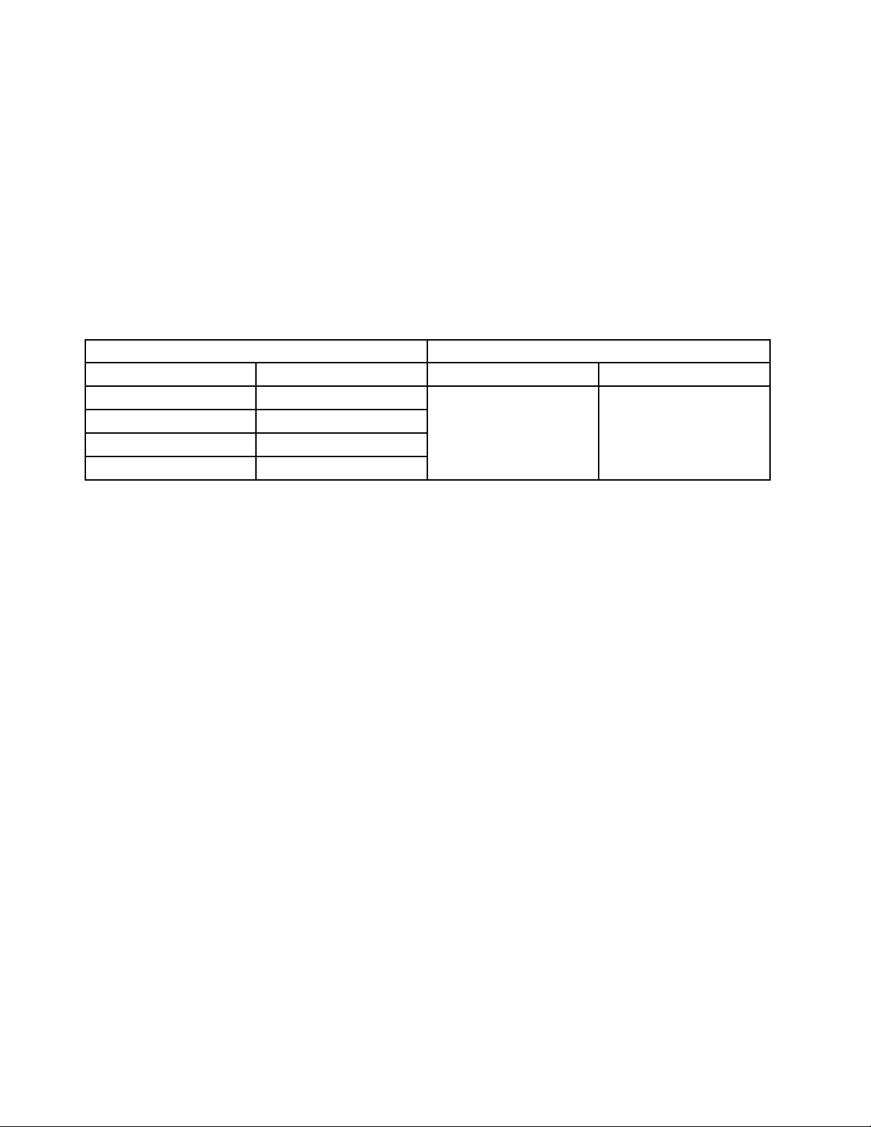
RoHScompliantThinkCentrepartshaveuniqueFRUpartnumbers.BeforeorafterJune2006,failedRoHS
compliantpartsmustalwaysbereplacedusingRoHScompliantFRUs,soonlytheFRUsidentiedas
compliantinthesystemhardwaremaintenancemanualordirectsubstitutionsforthoseFRUscanbeused.
ProductsmarketedbeforeJune2006ProductsmarketedafterJune2006
Currentororiginalpart
Non-RoHSCanbeNon-RoHS
Non-RoHSCanbeRoHS
Non-RoHSCansubstitutetoRoHS
RoHSMustbeRoHS
ReplacementFRU
Currentororiginalpart
MustbeRoHSMustbeRoHS
ReplacementFRU
Note:AdirectsubstitutionisapartwithadifferentFRUpartnumberthatisautomaticallyshippedbythe
distributioncenteratthetimeoforder.
2ThinkCentreHardwareMaintenanceManual
Page 11

Chapter2.Safetyinformation
Thischaptercontainsthesafetyinformationthatyouneedtobefamiliarwithbeforeservicingacomputer.
Generalsafety
Followtheserulestoensuregeneralsafety:
•Observegoodhousekeepingintheareaofthemachinesduringandaftermaintenance.
•Whenliftinganyheavyobject:
1.Ensureyoucanstandsafelywithoutslipping.
2.Distributetheweightoftheobjectequallybetweenyourfeet.
3.Useaslowliftingforce.Nevermovesuddenlyortwistwhenyouattempttolift.
4.Liftbystandingorbypushingupwithyourlegmuscles;thisactionremovesthestrainfromthe
musclesinyourback.Donotattempttoliftanyobjectsthatweighmorethan16kg(35lb)orobjects
thatyouthinkaretooheavyforyou.
•Donotperformanyactionthatcauseshazardstothecustomer,orthatmakestheequipmentunsafe.
•Beforeyoustartthemachine,ensurethatotherservicerepresentativesandthecustomer'spersonnelare
notinahazardousposition.
•Placeremovedcoversandotherpartsinasafeplace,awayfromallpersonnel,whileyouareservicing
themachine.
•Keepyourtoolcaseawayfromwalkareassothatotherpeoplewillnottripoverit.
•Donotwearlooseclothingthatcanbetrappedinthemovingpartsofamachine.Ensurethatyoursleeves
arefastenedorrolledupaboveyourelbows.Ifyourhairislong,fastenit.
•Inserttheendsofyournecktieorscarfinsideclothingorfastenitwithanonconductiveclip,approximately
8centimeters(3inches)fromtheend.
•Donotwearjewelry,chains,metal-frameeyeglasses,ormetalfastenersforyourclothing.
Remember:Metalobjectsaregoodelectricalconductors.
•Wearsafetyglasseswhenyouare:hammering,drilling,soldering,cuttingwire,attachingsprings,using
solvents,orworkinginanyotherconditionsthatmightbehazardoustoyoureyes.
•Afterservice,reinstallallsafetyshields,guards,labels,andgroundwires.Replaceanysafetydevice
thatiswornordefective.
•Reinstallallcoverscorrectlybeforereturningthemachinetothecustomer.
Electricalsafety
CAUTION:
Electricalcurrentfrompower,telephone,andcommunicationcablescanbehazardous.T oavoid
personalinjuryorequipmentdamage,disconnecttheattachedpowercords,telecommunication
systems,networks,andmodemsbeforeyouopenthecentrecovers,unlessinstructedotherwisein
theinstallationandcongurationprocedures.
Observethefollowingruleswhenworkingonelectricalequipment.
©CopyrightLenovo2011
3
Page 12

Important:Useonlyapprovedtoolsandtestequipment.Somehandtoolshavehandlescoveredwithasoft
materialthatdoesnotinsulateyouwhenworkingwithliveelectricalcurrents.Manycustomershave,near
theirequipment,rubberoormatsthatcontainsmallconductiveberstodecreaseelectrostaticdischarges.
Donotusethistypeofmattoprotectyourselffromanelectricshock.
•Findtheroomemergencypower-off(EPO)switch,disconnectingswitch,orelectricaloutlet.Ifanelectrical
accidentoccurs,youcanthenoperatetheswitchorunplugthepowercordquickly.
•Donotworkaloneunderhazardousconditionsornearequipmentthathashazardousvoltages.
•Disconnectallpowerbefore:
–Performingamechanicalinspection
–Workingnearpowersupplies
–RemovingorinstallingFieldReplaceableUnits(FRU)
•Beforeyoustarttoworkonthemachine,unplugthepowercord.Ifyoucannotunplugit,askthecustomer
topower-offthewallboxthatsuppliespowertothemachineandtolockthewallboxintheoffposition.
•Ifyouneedtoworkonamachinethathasexposedelectricalcircuits,observethefollowingprecautions:
–Ensurethatanotherperson,familiarwiththepower-offcontrols,isnearyou.
Remember:Anotherpersonmustbetheretoswitchoffthepower,ifnecessary.
–Useonlyonehandwhenworkingwithpowered-onelectricalequipment;keeptheotherhandinyour
pocketorbehindyourback.
Remember:Theremustbeacompletecircuittocauseanelectricshock.Byobservingtheabove
rule,youmaypreventacurrentfrompassingthroughyourbody.
–Whenusingatester,setthecontrolscorrectlyandusetheapprovedprobeleadsandaccessoriesfor
thattester.
–Standonsuitablerubbermats(obtainedlocally,ifnecessary)toinsulateyoufromgroundssuchas
metaloorstripsandmachineframes.
Observethespecialsafetyprecautionswhenyouworkwithveryhighvoltages;theseinstructionsarein
thesafetysectionsofmaintenanceinformation.Useextremecarewhenmeasuringhighvoltages.
•Regularlyinspectandmaintainyourelectricalhandtoolsforsafeoperationalcondition.
•Donotusewornorbrokentoolsandtesters.
•Neverassumethatpowerhasbeendisconnectedfromacircuit.First,checkthatithasbeenpowered-off.
•Alwayslookcarefullyforpossiblehazardsinyourworkarea.Examplesofthesehazardsaremoistoors,
nongroundedpowerextensioncables,powersurges,andmissingsafetygrounds.
•Donottouchliveelectricalcircuitswiththereectivesurfaceofaplasticdentalmirror.Thesurfaceis
conductive;suchtouchingcancausepersonalinjuryandmachinedamage.
•Donotservicethefollowingpartswiththepoweronwhentheyareremovedfromtheirnormaloperating
placesinamachine:
–Powersupplyunits
–Pumps
–Blowersandfans
–Motorgenerators
andsimilarunits.(Thispracticeensurescorrectgroundingoftheunits.)
•Ifanelectricalaccidentoccurs:
–Usecaution;donotbecomeavictimyourself.
–Switchoffpower.
–Sendanotherpersontogetmedicalaid.
4ThinkCentreHardwareMaintenanceManual
Page 13

Voltage-selectionswitch
Somecomputersareequippedwithavoltage-selectionswitchlocatednearthepower-cordconnection
pointonthecomputer.Ifyourcomputerhasavoltage-selectionswitch,ensurethatyousettheswitchto
matchthevoltageavailableatyourelectricaloutlet.Settingthevoltage-selectionswitchincorrectlycan
causepermanentdamagetothecomputer.
Ifyourcomputerdoesnothaveavoltage-selectionswitch,yourcomputerisdesignedtooperateonlyatthe
voltageprovidedinthecountryorregionwherethecomputerwasoriginallypurchased.
Ifyourelocateyourcomputertoanothercountry,beawareofthefollowing:
•Ifyourcomputerdoesnothaveavoltage-selectionswitch,donotconnectthecomputertoanelectrical
outletuntilyouhaveveriedthatthevoltageprovidedisthesameasitwasinthecountryorregion
wherethecomputerwasoriginallypurchased.
•Ifyourcomputerhasavoltage-selectionswitch,donotconnectthecomputertoanelectricaloutletuntil
youhaveveriedthatthevoltage-selectionswitchissettomatchthevoltageprovidedinthatcountry
orregion.
Ifyouarenotsureofthevoltageprovidedatyourelectricaloutlet,contactyourlocalelectriccompanyor
refertoofcialWebsitesorotherliteraturefortravelerstothecountryorregionwhereyouarelocated.
Safetyinspectionguide
Theintentofthisinspectionguideistoassistyouinidentifyingpotentiallyunsafeconditionsonthese
products.Eachmachine,asitwasdesignedandbuilt,hadrequiredsafetyitemsinstalledtoprotectusers
andservicepersonnelfrominjury.Thisguideaddressesonlythoseitems.However,goodjudgmentshould
beusedtoidentifypotentialsafetyhazardsduetoattachmentoffeaturesoroptionsnotcoveredbythis
inspectionguide.
Ifanyunsafeconditionsarepresent,youmustdeterminehowserioustheapparenthazardcouldbeand
whetheryoucancontinuewithoutrstcorrectingtheproblem.
Considertheseconditionsandthesafetyhazardstheypresent:
•Electricalhazards,especiallyprimarypower(primaryvoltageontheframecancauseseriousorfatal
electricalshock).
•Explosivehazards,suchasadamagedCRTfaceorbulgingcapacitor
•Mechanicalhazards,suchaslooseormissinghardware
Theguideconsistsofaseriesofstepspresentedinachecklist.Beginthecheckswiththepoweroff,and
thepowercorddisconnected.
Checklist:
1.Checkexteriorcoversfordamage(loose,broken,orsharpedges).
2.Power-offthecomputer.Disconnectthepowercord.
3.Checkthepowercordfor:
a.Athird-wiregroundconnectoringoodcondition.Useametertomeasurethird-wireground
continuityfor0.1ohmorlessbetweentheexternalgroundpinandframeground.
b.Thepowercordshouldbetheappropriatetypeasspeciedinthepartslistings.
c.Insulationmustnotbefrayedorworn.
4.Removethecover.
Chapter2.Safetyinformation5
Page 14

5.Checkforanyobviousalterations.Usegoodjudgmentastothesafetyofanyalterations.
6.Checkinsidetheunitforanyobviousunsafeconditions,suchasmetallings,contamination,wateror
otherliquids,orsignsofreorsmokedamage.
7.Checkforworn,frayed,orpinchedcables.
8.Checkthatthepower-supplycoverfasteners(screwsorrivets)havenotbeenremovedortamperedwith.
Handlingelectrostaticdischarge-sensitivedevices
Anycomputerpartcontainingtransistorsorintegratedcircuits(ICs)shouldbeconsideredsensitiveto
electrostaticdischarge(ESD).ESDdamagecanoccurwhenthereisadifferenceinchargebetweenobjects.
ProtectagainstESDdamagebyequalizingthechargesothatthemachine,thepart,theworkmat,andthe
personhandlingthepartareallatthesamecharge.
Notes:
1.Useproduct-specicESDprocedureswhentheyexceedtherequirementsnotedhere.
2.MakesurethattheESDprotectivedevicesyouusehavebeencertied(ISO9000)asfullyeffective.
WhenhandlingESD-sensitiveparts:
•Keepthepartsinprotectivepackagesuntiltheyareinsertedintotheproduct.
•Avoidcontactwithotherpeoplewhilehandlingthepart.
•Wearagroundedwriststrapagainstyourskintoeliminatestaticonyourbody.
•Preventthepartfromtouchingyourclothing.Mostclothingisinsulativeandretainsachargeevenwhen
youarewearingawriststrap.
•Usetheblacksideofagroundedworkmattoprovideastatic-freeworksurface.Thematisespecially
usefulwhenhandlingESD-sensitivedevices.
•Selectagroundingsystem,suchasthoselistedbelow,toprovideprotectionthatmeetsthespecic
servicerequirement.
Note:TheuseofagroundingsystemisdesirablebutnotrequiredtoprotectagainstESDdamage.
–AttachtheESDgroundcliptoanyframeground,groundbraid,orgreen-wireground.
–UseanESDcommongroundorreferencepointwhenworkingonadouble-insulatedor
battery-operatedsystem.Youcanusecoaxorconnector-outsideshellsonthesesystems.
–Usetheroundground-prongoftheacplugonac-operatedcomputers.
Groundingrequirements
Electricalgroundingofthecomputerisrequiredforoperatorsafetyandcorrectsystemfunction.Proper
groundingoftheelectricaloutletcanbeveriedbyacertiedelectrician.
Safetynotices(multi-lingualtranslations)
Thecautionanddangersafetynoticesinthissectionareprovidedinthefollowinglanguages:
•English
•Arabic
•Brazilian/Portuguese
•Chinese(simplied)
•Chinese(traditional)
6ThinkCentreHardwareMaintenanceManual
Page 15
•French
•German
•Hebrew
•Italian
•Korean
•Spanish
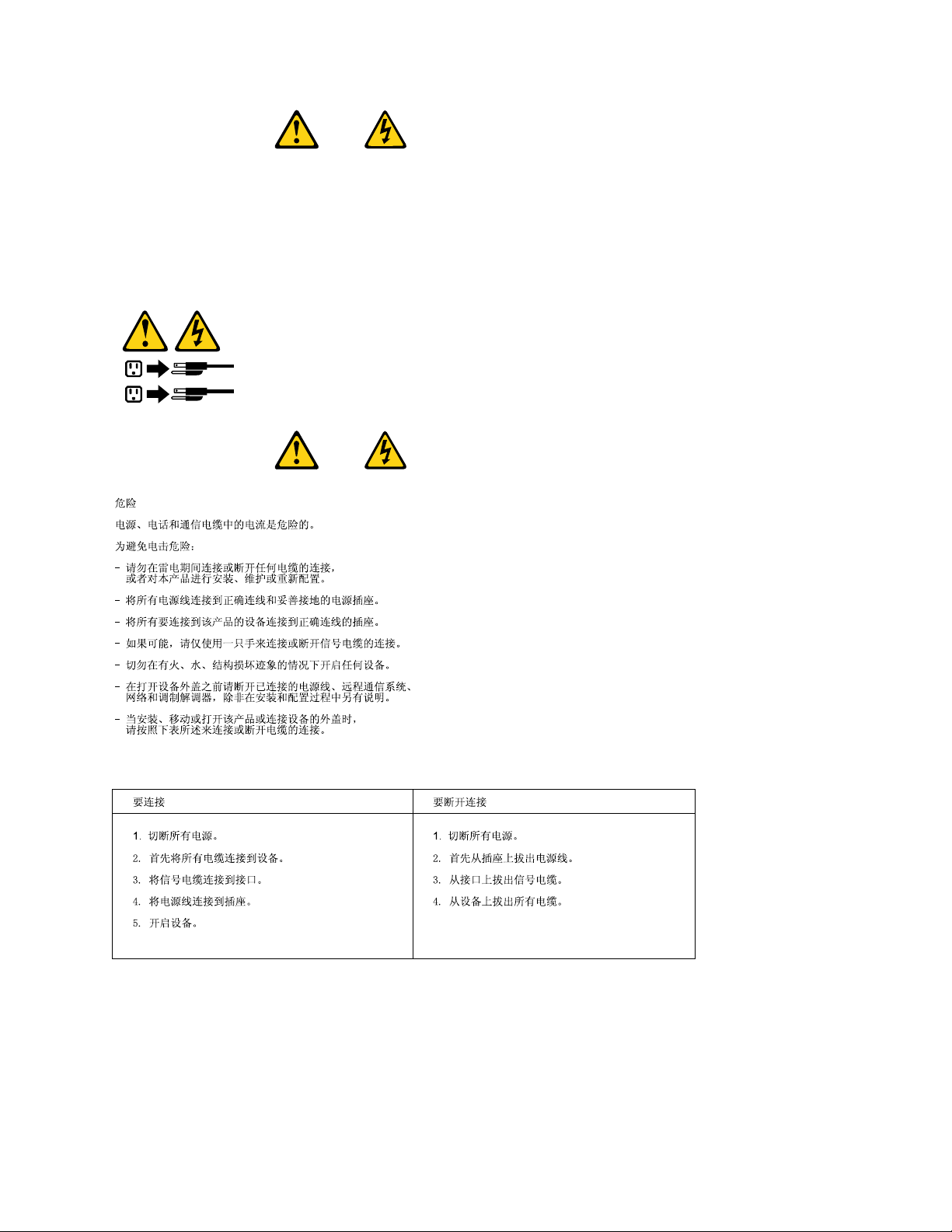
DANGER
Electricalcurrentfrompower,telephoneandcommunicationcablesishazardous.
Toavoidashockhazard:
•Donotconnectordisconnectanycablesorperforminstallation,maintenance,orreconguration
ofthisproductduringanelectricalstorm.
•Connectallpowercordstoaproperlywiredandgroundedelectricaloutlet.
•Connecttoproperlywiredoutletsanyequipmentthatwillbeattachedtothisproduct.
•Whenpossible,useonehandonlytoconnectordisconnectsignalcables.
•Neverturnonanyequipmentwhenthereisevidenceofre,water,orstructuraldamage.
•Disconnecttheattachedpowercords,telecommunicationssystems,networks,andmodems
beforeyouopenthedevicecovers,unlessinstructedotherwiseintheinstallationandconguration
procedures.
•Connectanddisconnectcablesasdescribedinthefollowingtableswheninstalling,moving,or
openingcoversonthisproductorattacheddevices.
ToConnectToDisconnect
1.TurneverythingOFF .
2.First,attachallcablestodevices.
3.Attachsignalcablestoconnectors.
4.Attachpowercordstooutlet.
5.TurndeviceON.
1.TurneverythingOFF.
2.First,removepowercordsfromoutlet.
3.Removesignalcablesfromconnectors.
4.Removeallcablesfromdevices.
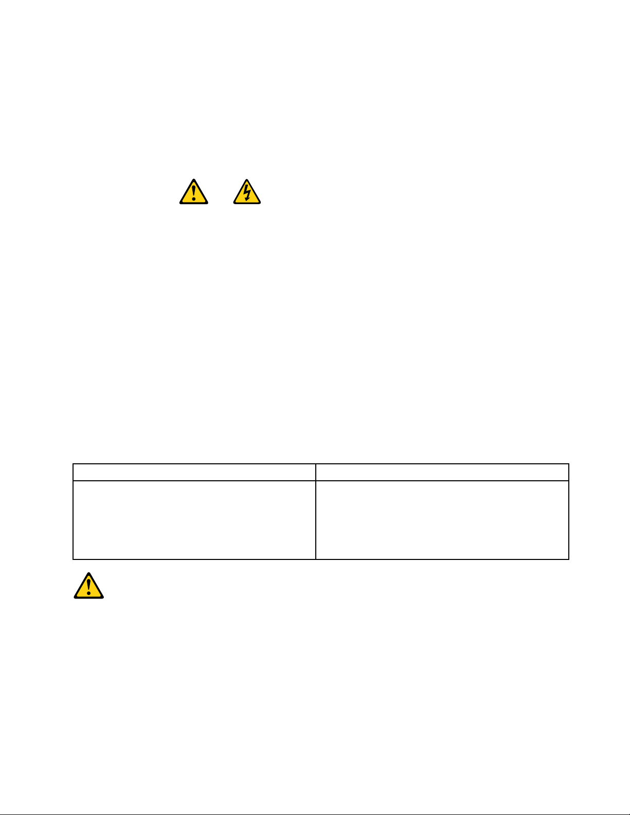
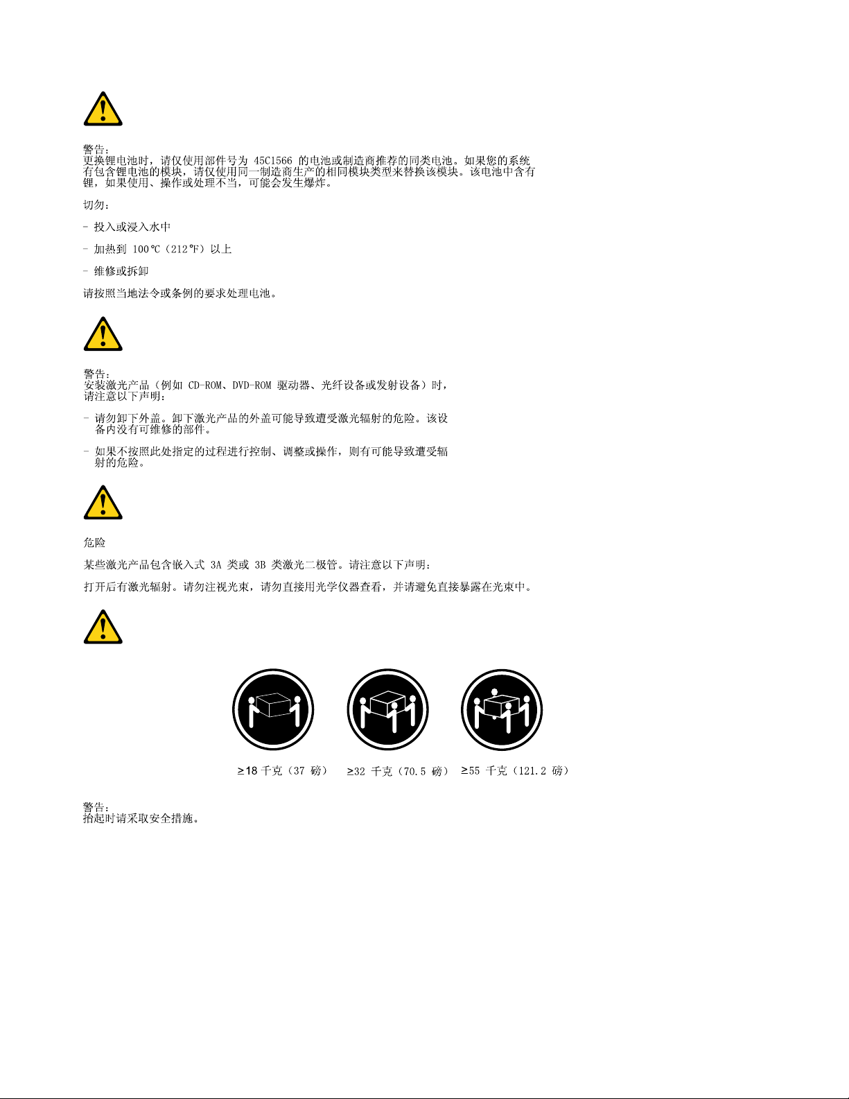
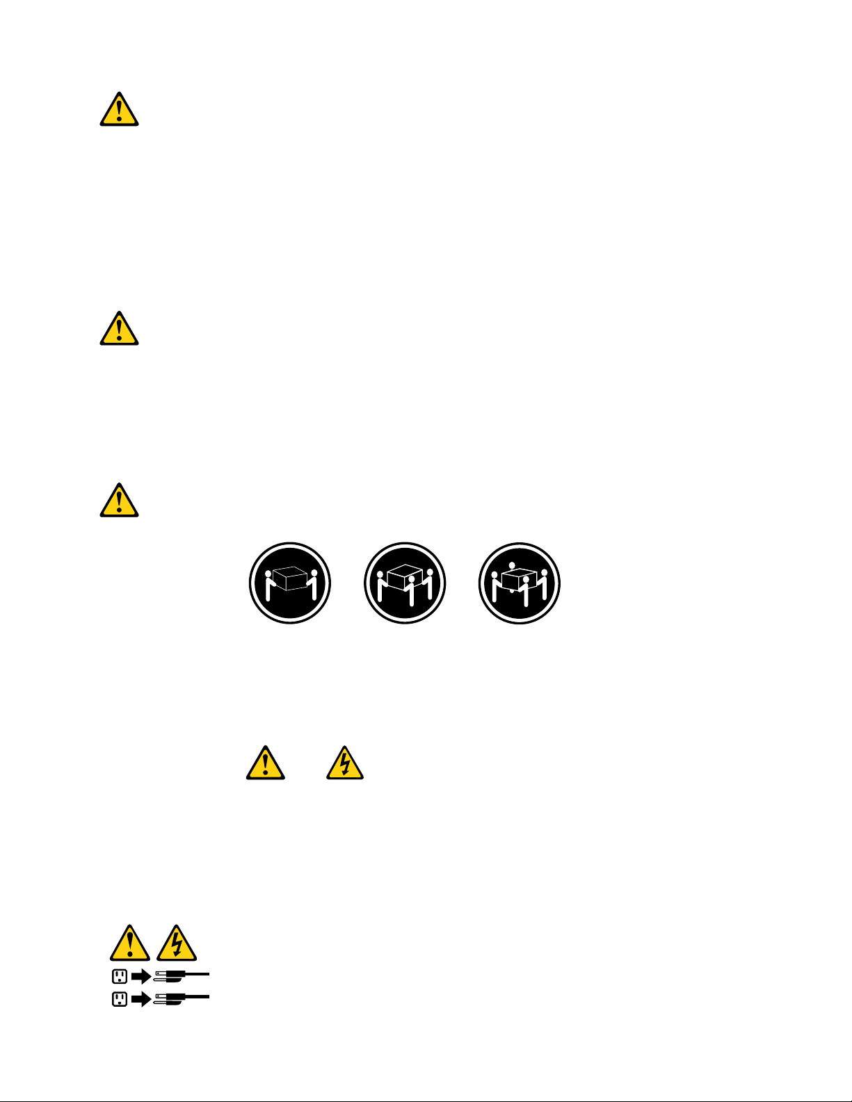
CAUTION:
Whenreplacingthelithiumbattery,useonlyPartNumber45C1566oranequivalenttypebattery
recommendedbythemanufacturer.Ifyoursystemhasamodulecontainingalithiumbattery,replace
itonlywiththesamemoduletypemadebythesamemanufacturer.Thebatterycontainslithiumand
canexplodeifnotproperlyused,handled,ordisposedof.Donot:
•Throworimmerseintowater
•Heattomorethan100°C(212°F)
•Repairordisassemble
Disposeofthebatteryasrequiredbylocalordinancesorregulations.
Chapter2.Safetyinformation7
Page 16
CAUTION:
1
2
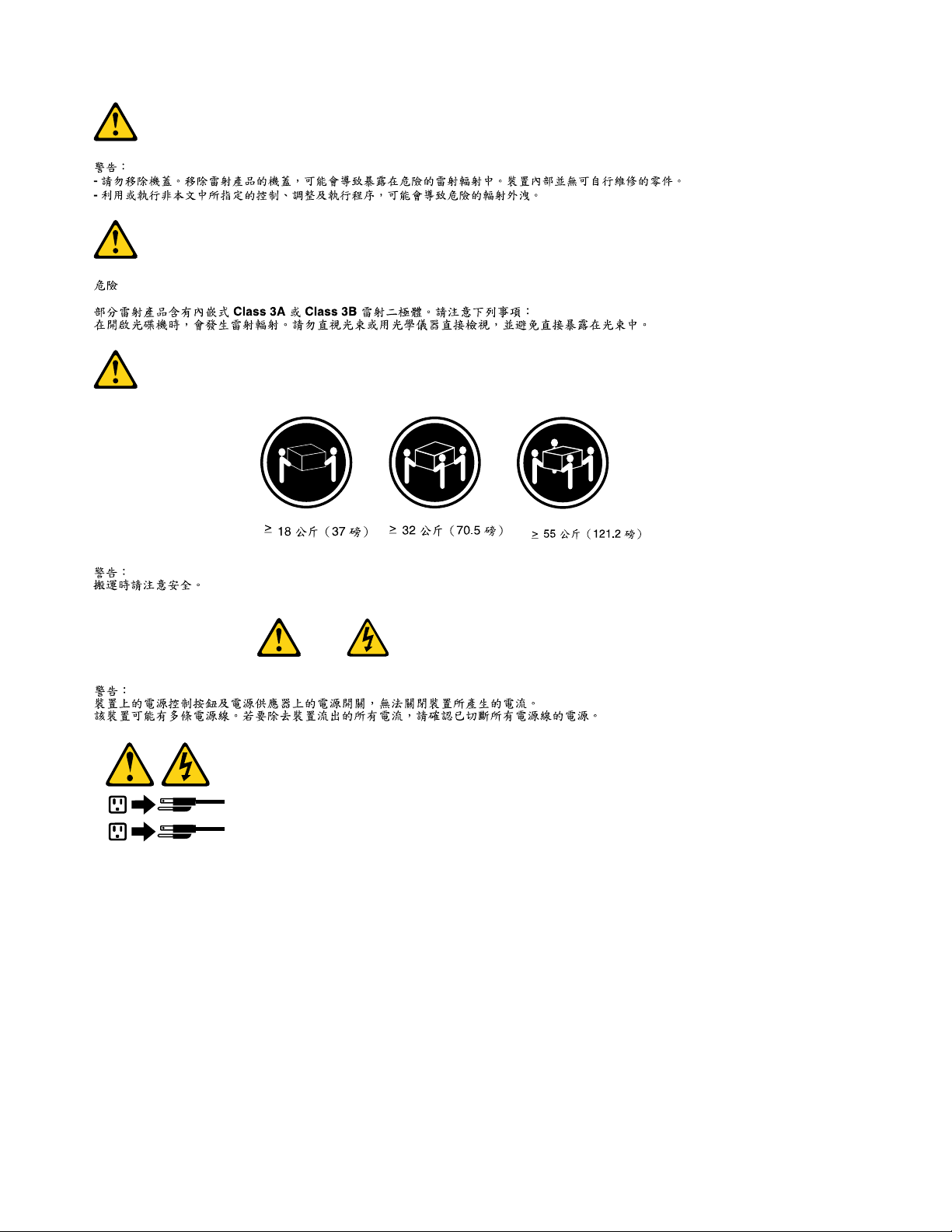
Whenlaserproducts(suchasCD-ROMs,DVD-ROMdrives,beropticdevices,ortransmitters)are
installed,notethefollowing:
•Donotremovethecovers.Removingthecoversofthelaserproductcouldresultinexposureto
hazardouslaserradiation.Therearenoserviceablepartsinsidethedevice.
•Useofcontrolsoradjustmentsorperformanceofproceduresotherthanthosespeciedherein
mightresultinhazardousradiationexposure.
DANGER
SomelaserproductscontainanembeddedClass3AorClass3Blaserdiode.Notethefollowing:
Laserradiationwhenopen.Donotstareintothebeam,donotviewdirectlywithoptical
instruments,andavoiddirectexposuretothebeam.
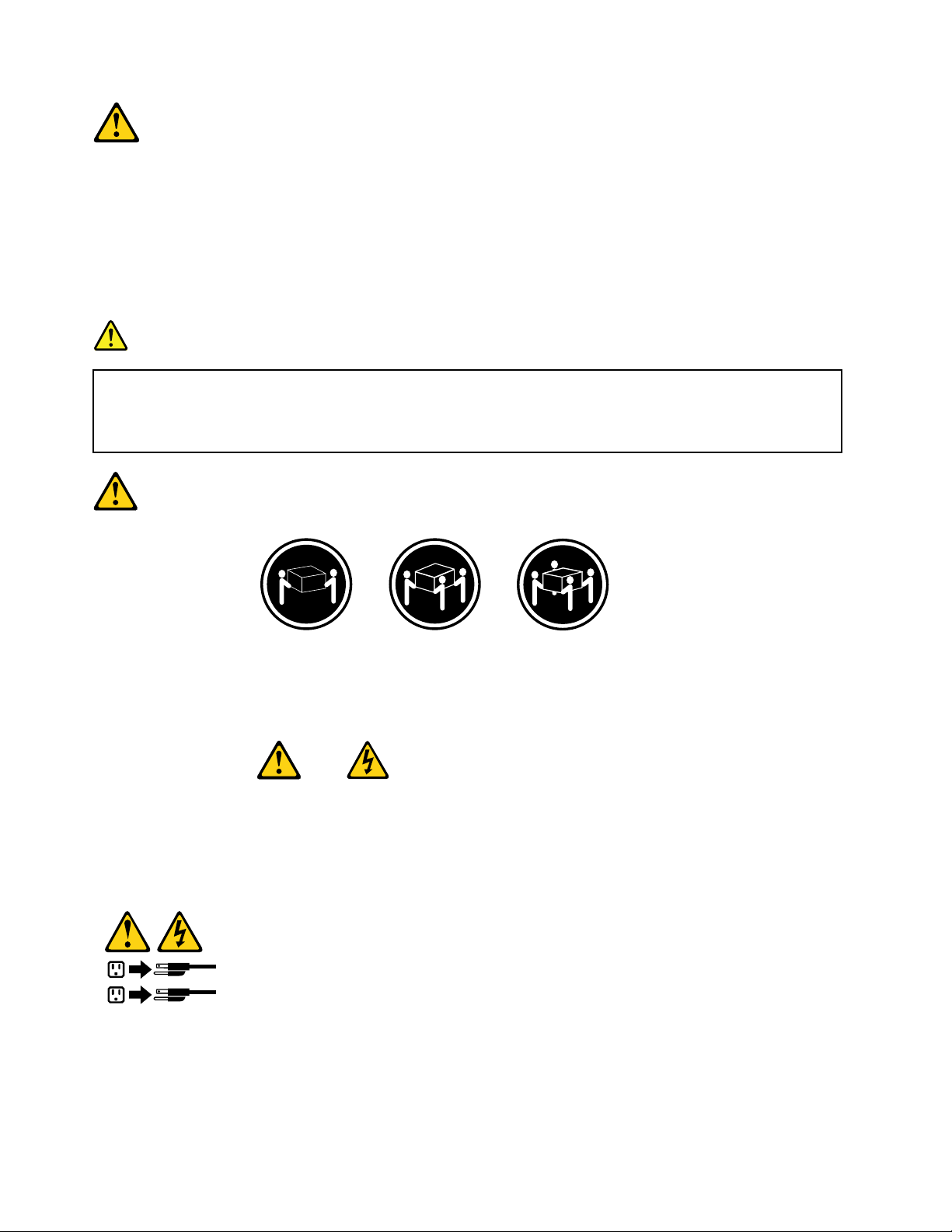
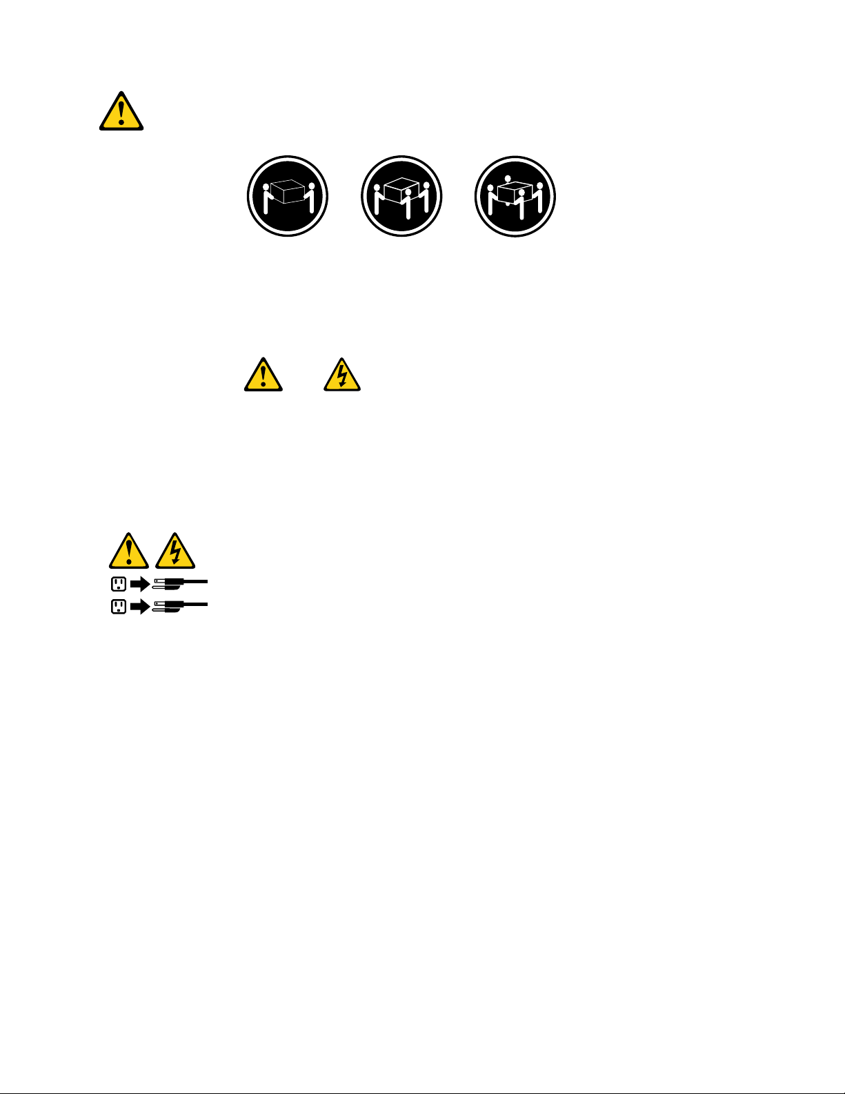
≥18kg(37lbs)≥32kg(70.5lbs)≥55kg(121.2lbs)
CAUTION:
Usesafepracticeswhenlifting.
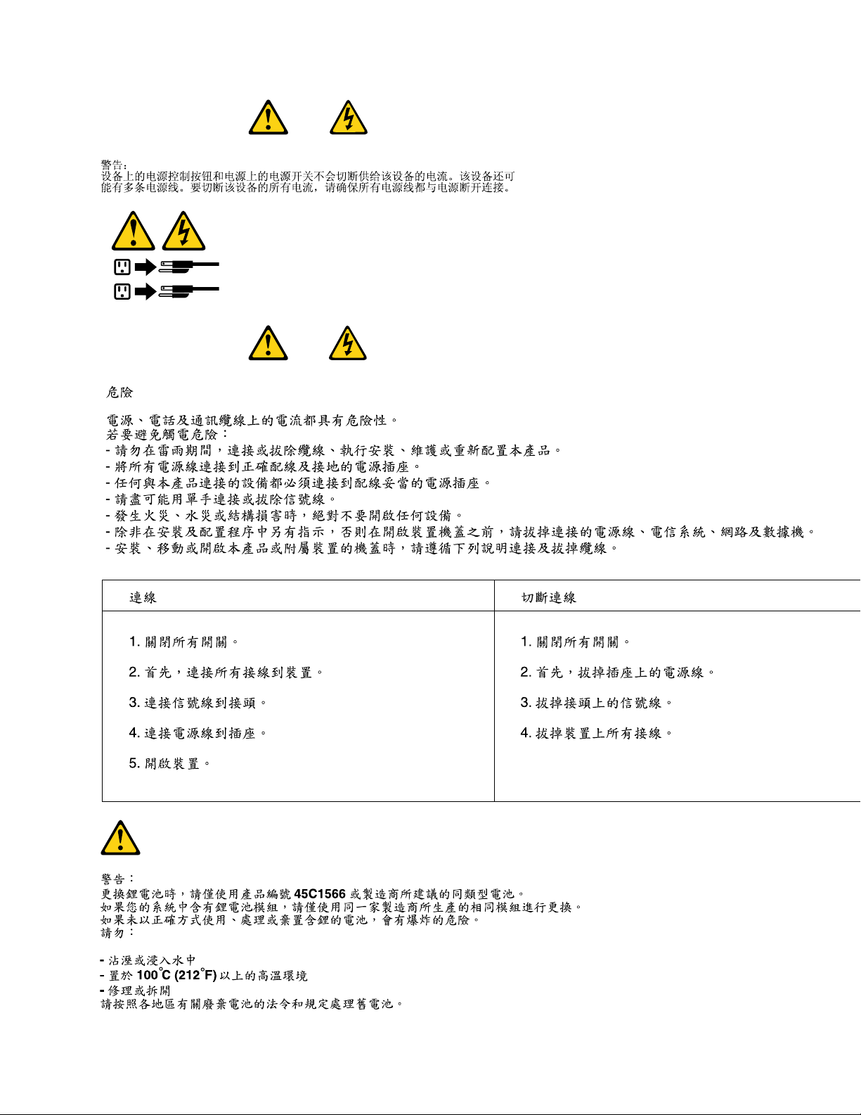
CAUTION:
Thepowercontrolbuttononthedeviceandthepowerswitchonthepowersupplydonotturnoff
theelectricalcurrentsuppliedtothedevice.Thedevicealsomighthavemorethanonepower
cord.Toremoveallelectricalcurrentfromthedevice,ensurethatallpowercordsaredisconnected
fromthepowersource.
8ThinkCentreHardwareMaintenanceManual
Page 17
Chapter2.Safetyinformation9
Page 18
≥18kg(37lbs)≥32kg(70.5lbs)≥55kg(121.2lbs)
10ThinkCentreHardwareMaintenanceManual
Page 19
1
2
PERIGO
Acorrenteelétricaprovenientedecabosdealimentação,detelefoneedecomunicaçõeséperigosa.
Paraevitarriscodechoqueelétrico:
•Nãoconectenemdesconectenenhumcaboouexecuteinstalação,manutençãooureconguração
desteprodutoduranteumatempestadecomraios.
•Conectetodososcabosdealimentaçãoatomadaselétricascorretamenteinstaladaseaterradas.
•T odoequipamentoqueforconectadoaesteprodutodeveserconectadoatomadascorretamente
instaladas.
•Quandopossível,utilizeapenasumadasmãosparaconectaroudesconectarcabosdesinal.
•Nuncaliguenenhumequipamentoquandohouverevidênciadefogo,águaoudanosestruturais.
•Antesdeabrirtampasdedispositivos,desconectecabosdealimentação,sistemasdetelecomunicação,
redesemodemsconectados,amenosqueespecicadodemaneiradiferentenosprocedimentosde
instalaçãoeconguração.
•Conecteedesconecteoscabosconformedescritonatabelaapresentadaaseguiraoinstalar,moverou
abrirtampasdesteprodutooudedispositivosconectados.
ParaConectar:ParaDesconectar:
1.DESLIGUETudo.
2.Primeiramente,conectetodososcabosaos
dispositivos.
3.Conecteoscabosdesinalaosconectores.
4.Conecteoscabosdealimentaçãoàstomadas.
5.LIGUEosdispositivos.
1.DESLIGUETudo.
2.Primeiramente,removaoscabosdealimentaçãodas
tomadas.
3.Removaoscabosdesinaldosconectores.
4.Removatodososcabosdosdispositivos.
Chapter2.Safetyinformation11
Page 20
CUIDADO:
Aosubstituirabateriadelítio,utilizeapenasumabateriacomNúmerodePeça45C1566ouumtipo
debateriaequivalenterecomendadopeloSeoseusistemapossuiummódulocomumabateriade
lítio,substitua-oapenasporummódulodomesmotipoedomesmofabricante.Abateriacontémlítio
epodeexplodirsenãoforutilizada,manuseadaoudescartadademaneiracorreta.
Não:
•Jogueoucoloquenaágua
•Aqueçaamaisde100°C(212°F)
•Consertenemdesmonte
Descarteabateriaconformerequeridopelasleisouregulamentoslocais.
PRECAUCIÓN:
Quandoprodutosalaser(comounidadesdeCD-ROMs,unidadesdeDVD-ROM,dispositivosdebraótica
outransmissores)estivereminstalados,observeoseguinte:
•Nãoremovaastampas.Aremoçãodastampasdeumprodutoalaserpoderesultaremexposição
prejudicialàradiaçãodelaser.Nãoexistempeçasquepodemserconsertadasnointeriordodispositivo.
•Autilizaçãodecontrolesouajustesouaexecuçãodeprocedimentosdiferentesdosespecicadosaqui
poderesultaremexposiçãoprejudicialàradiação.
PERIGO
AlgunsprodutosalasercontêmdiododelaserintegradodaClasse3AoudaClasse3B.Observeoseguinte:
Radiaçãoalaserquandoaberto.Nãoolhediretamenteparaofeixeaolhonuoucominstrumentosópticose
eviteexposiçãodiretaaofeixe.
≥18kg(37lbs)≥32kg(70.5lbs)≥55kg(121.2lbs)
CUIDADO:
Utilizeprocedimentosdesegurançaparalevantarequipamentos.
12ThinkCentreHardwareMaintenanceManual
Page 21
CUIDADO:
1
2
Obotãodecontroledealimentaçãododispositivoeobotãoparaligar/desligardafontedealimentação
nãodesligamacorrenteelétricafornecidaaodispositivo.Odispositivotambémpodetermaisdeumcabo
dealimentação.Pararemovertodaacorrenteelétricadodispositivo,assegurequetodososcabosde
alimentaçãoestejamdesconectadosdafontedealimentação.
Chapter2.Safetyinformation13
Page 22
14ThinkCentreHardwareMaintenanceManual
Page 23
1
2
Chapter2.Safetyinformation15
Page 24
1
2
16ThinkCentreHardwareMaintenanceManual
Page 25
DANGER
Lecourantélectriqueprovenantdel'alimentation,dutéléphoneetdescâblesdetransmissionpeutprésenter
undanger.
Pourévitertoutrisquedechocélectrique:
•Nemanipulezaucuncâbleetn'effectuezaucuneopérationd'installation,d'entretienoudereconguration
deceproduitaucoursd'unorage.
•Brancheztouslescordonsd'alimentationsurunsocledeprisedecourantcorrectementcâbléetmisàla
terre.
•Branchezsurdessoclesdeprisedecourantcorrectementcâbléstoutéquipementconnectéàceproduit.
•Lorsquecelaestpossible,n'utilisezqu'uneseulemainpourconnecteroudéconnecterlescâbles
d'interface.
•Nemettezjamaisunéquipementsoustensionencasd'incendieoud'inondation,ouenprésencede
dommagesmatériels.
•Avantderetirerlescartersdel'unité,mettezcelle-cihorstensionetdéconnectezsescordons
d'alimentation,ainsiquelescâblesquilarelientauxréseaux,auxsystèmesdetélécommunicationetaux
modems(saufinstructioncontrairementionnéedanslesprocéduresd'installationetdeconguration).
•Lorsquevousinstallez,quevousdéplacez,ouquevousmanipulezleprésentproduitoudespériphériques
quiluisontraccordés,reportez-vousauxinstructionsci-dessouspourconnecteretdéconnecterles
différentscordons.
ConnexionDéconnexion
1.MettezlesunitésHORSTENSION.
2.Commencezparbranchertouslescordonssurles
unités.
3.Branchezlescâblesd'interfacesurdesconnecteurs.
4.Branchezlescordonsd'alimentationsurdesprises.
5.MettezlesunitésSOUSTENSION.
1.MettezlesunitésHORSTENSION.
2.Débranchezlescordonsd'alimentationdesprises.
3.Débranchezlescâblesd'interfacedesconnecteurs.
4.Débrancheztouslescâblesdesunités.
Chapter2.Safetyinformation17
Page 26
ATTENTION:
Remplacerlapileaulithiumusagéeparunepilederéférenceidentiqueexclusivement,(référence
45C1566),ousuivrelesinstructionsdufabricantquiendénitleséquivalences.Sivotresystèmeest
dotéd'unmodulecontenantunepileaulithium,vousdevezleremplaceruniquementparunmodule
identique,produitparlemêmefabricant.Lapilecontientdulithiumetpeutexploserencasde
mauvaiseutilisation,demauvaisemanipulationoudemiseaurebutinappropriée.
Nepas:
•lajeteràl'eau,
•l'exposeràdestempératuressupérieuresà100°C,
•chercheràlaréparerouàladémonter.
Nepasmettrelapileàlapoubelle.Pourlamiseaurebut,sereporteràlaréglementationenvigueur.
ATTENTION:
Sidesproduitsàlaser(telsquedesunitésdeCD-ROM,deDVD-ROM,desunitésàbresoptiques,ou
desémetteurs)sontinstallés,prenezconnaissancedesinformationssuivantes:
•Neretirezpaslecarter.Enouvrantl'unitédeCD-ROMoudeDVD-ROM,vousvousexposezau
rayonnementdangereuxdulaser.Aucunepiècedel'unitén'estréparable.
•Pourévitertoutrisqued'expositionaurayonlaser,respectezlesconsignesderéglageet
d'utilisationdescommandes,ainsiquelesprocéduresdécritesdansleprésentmanuel.
DANGER
Certainsproduitsàlasercontiennentunediodeàlaserintégréedeclasse3Aou3B.Prenez
connaissancedesinformationssuivantes:
Rayonnementlaserlorsquelecarterestouvert.Eviteztouteexpositiondirecteaurayonlaser.Evitez
deregarderxementlefaisceauoudel'observeràl'aided'instrumentsoptiques.
18ThinkCentreHardwareMaintenanceManual
Page 27
≥18kg(37lbs)≥32kg(70.5lbs)≥55kg(121.2lbs)
1
2
ATTENTION:
Soulevezlamachineavecprécaution.
ATTENTION:
L'interrupteurdecontrôled'alimentationdel'unitéetl'interrupteurdublocd'alimentationnecoupent
paslecourantélectriquealimentantl'unité.Enoutre,lesystèmepeutêtreéquipédeplusieurs
cordonsd'alimentation.Pourmettrel'unitéhorstension,vousdevezdéconnectertouslescordons
delasourced'alimentation.
Chapter2.Safetyinformation19
Page 28
VORSICHT
AnNetz-,Telefon-undDatenleitungenkönnengefährlicheSpannungenanliegen.
AusSicherheitsgründen:
•BeiGewitterandiesemGerätkeineKabelanschließenoderlösen.FernerkeineInstallations-,
Wartungs-oderRekongurationsarbeitendurchführen.
•GerätnuraneineSchutzkontaktsteckdosemitordnungsgemäßgeerdetemSchutzkontakt
anschließen.
•AlleangeschlossenenGeräteebenfallsanSchutzkontaktsteckdosenmitordnungsgemäß
geerdetemSchutzkontaktanschließen.
•DieSignalkabelnachMöglichkeiteinhändiganschließenoderlösen,umeinenStromschlagdurch
BerührenvonOberächenmitunterschiedlichemelektrischemPotenzialzuvermeiden.
•Geräteniemalseinschalten,wennHinweiseaufFeuer,WasseroderGebäudeschädenvorliegen.
•DieVerbindungzudenangeschlossenenNetzkabeln,Telekommunikationssystemen,Netzwerken
undModemsistvordemÖffnendesGehäuseszuunterbrechen,sofernindenInstallations-und
KongurationsprozedurenkeineanderslautendenAnweisungenenthaltensind.
•ZumInstallieren,TransportierenundÖffnenderAbdeckungendesComputersoderder
angeschlossenenEinheitendieKabelgemäßderfolgendenTabelleanschließenundabziehen.
ZumAnschließenderKabelgehenSiewiefolgtvorZumAbziehenderKabelgehenSiewiefolgtvor
1.SchaltenSiealleEinheitenAUS.
2.SchließenSieerstalleKabelandieEinheitenan.
3.SchließenSiedieSignalkabelandieBuchsenan.
4.SchließenSiedieNetzkabelandieSteckdosean.
5.SchaltenSiedieEinheitEIN.
1.SchaltenSiealleEinheitenAUS.
2.ZiehenSiezuerstalleNetzkabelausden
Netzsteckdosen.
3.ZiehenSiedieSignalkabelausdenBuchsen.
4.ZiehenSiealleKabelvondenEinheitenab.
CAUTION:
EineverbrauchteLithiumbatterienurdurcheineBatteriemitderT eilenummer45C1566odereine
gleichwertige,vomHerstellerempfohleneBatterieersetzen.EnthältdasSystemeinModulmiteiner
Lithiumbatterie,diesesnurdurcheinModuldesselbenTypsundvondemselbenHerstellerersetzen.
DieBatterieenthältLithiumundkannbeiunsachgemäßerVerwendung,HandhabungoderEntsorgung
explodieren.
DieBatterienicht:
•mitWasserinBerührungbringen.
•über100Cerhitzen.
•reparierenoderzerlegen.
DieörtlichenBestimmungenfürdieEntsorgungvonSondermüllbeachten.
20ThinkCentreHardwareMaintenanceManual
Page 29
ACHTUNG:
1
2
BeiderInstallationvonLasergeräten(wieCD-ROM-Laufwerken,DVD-aufwerken,Einheitenmit
LichtwellenleitertechnikoderSendern)Folgendesbeachten:
•DieAbdeckungennichtentfernen.DurchEntfernenderAbdeckungendesLasergerätskönnen
gefährlicheLaserstrahlungenfreigesetztwerden.DasGerätenthältkeinezuwartendenTeile.
•WerdenSteuerelemente,EinstellungenoderDurchführungenvonProzedurenandersalshier
angegebenverwendet,kanngefährlicheLaserstrahlungauftreten.
VORSICHT
EinigeLasergeräteenthalteneineLaserdiodederKlasse3Aoder3B.BeachtenSieFolgendes:
LaserstrahlungbeigeöffneterVerkleidung.NichtindenStrahlblicken.KeineLupenoderSpiegel
verwenden.Strahlungsbereichmeiden.
≥18kg(37lbs)≥32kg(70.5lbs)≥55kg(121.2lbs)
ACHTUNG:
ArbeitsschutzrichtlinienbeimAnhebenderMaschinebeachten.
ACHTUNG:
MitdemNetzschalteranderEinheitundamNetzteilwirddieStromversorgungfürdieEinheit
nichtunterbrochen.DieEinheitkannauchmitmehrerenNetzkabelnausgestattetsein.Umdie
StromversorgungfürdieEinheitvollständigzuunterbrechen,müssenallezumGerätführenden
NetzkabelvomNetzgetrenntwerden.
Chapter2.Safetyinformation21
Page 30
22ThinkCentreHardwareMaintenanceManual
Page 31

1
2
Chapter2.Safetyinformation23
Page 32

PERICOLO
Lacorrenteelettricaprovenientedaicavidialimentazione,deltelefonoedicomunicazionepuòessere
pericolosa.
Perevitareilrischiodiscosseelettriche:
•Noncollegareoscollegarequalsiasicavooppureeffettuarel'installazione,lamanutenzioneola
ricongurazionedelprodottoduranteuntemporale.
•Collegaretuttiilielettriciaunapresadialimentazionecorrettamentecablataedotatadimessaa
terra.
•Collegareallepreseelettricheappropriatetutteleapparecchiaturecheverrannoutilizzateper
questoprodotto.
•Sepossibile,utilizzaresolounamanopercollegareoscollegareicavidisegnale.
•Nonaccendereassolutamenteapparecchiatureinpresenzadiincendi,perdited'acquaodanno
strutturale.
•Scollegareicavidialimentazione,isistemiditelecomunicazione,leretieilmodemprimadi
aprireicoperchideldispositivo,salvoistruzionicontrarierelativealleprocedurediinstallazionee
congurazione.
•Collegareescollegareicavicomedescrittonellaseguentetabellaquandovengonoeffettuate
operazionidiinstallazione,spostamentooaperturadeicoperchidiquestoprodottoodelleunità
collegate.
PercollegarsiPerscollegarsi
1.SPEGNEREleapparecchiature.
2.Innanzitutto,collegaretuttiicavialleunità.
3.Collegareicavidisegnaleaiconnettori.
4.Collegareicavidialimentazioneallapresa.
5.Accenderel'unità.
1.SPEGNEREleapparecchiature.
2.Innanzitutto,rimuovereicavidialimentazionedalla
presa.
3.Rimuovereicavidisegnaledaiconnettori.
4.Rimuoveretuttiicavidalleunità.
24ThinkCentreHardwareMaintenanceManual
Page 33

ATTENZIONE:
Quandosisostituiscelabatteriaallitio,utilizzaresoloilNumeroparte45C1566ountipodibatteria
equivalenteconsigliatodalproduttore.Sesulsistemaèpresenteunmodulochecontieneunabatteria
allitio,sostituirlosoloconuntipodimodulodellostessotipodellastessacasadiproduzione.La
batteriacontienelitioepuòesplodereseusata,maneggiataosmaltitainmodononcorretto.
Non:
•Gettareoimmergerelabatterianell'acqua
•Riscaldarlaadunatemperaturasuperioreai100gradiC(212gradiF)
•Smontarla,ricaricarlaotentarediripararla
Lebatterieusatevannosmaltiteinaccordoallanormativainvigore(DPR915/82esuccessive
disposizioniedisposizionilocali).
ATTENZIONE:
Quandovengonoinstallatiprodottilaser(qualiCD-ROM,unitàDVD-ROM,unitàabreotticheo
trasmittenti),tenerpresentequantosegue:
•Nonrimuovereglisportelli.L'aperturadiun'unitàlaserpuòdeterminarel'esposizionearadiazioni
laserpericolose.All'internodell'unitànonvisonopartisucuieffettuarel'assistenzatecnica.
•L'utilizzodicontrolli,regolazioniol'esecuzionediprocedurenondescrittinelpresentemanuale
possonoprovocarel'esposizionearadiazionipericolose.
PERICOLO
AlcuneunitàlasercontengonoundiodolaserdiClasse3AoClasse3B.Tenerpresentequantosegue:
Aprendol'unitàvengonoemesseradiazionilaser.Nonssareilfascio,nonguardarlodirettamente
construmentiotticiedevitarel'esposizionealfascio.
Chapter2.Safetyinformation25
Page 34

≥18kg(37lbs)≥32kg(70.5lbs)≥55kg(121.2lbs)
1
2
ATTENZIONE:
Prestareattenzionenelsollevarel'apparecchiatura.
ATTENZIONE:
Ilpulsantedicontrollodell'alimentazionepresentesull'unitàel'interruttoredell'alimentatorenon
disattivanol'alimentazionecorrentefornitaall'unità.E'possibilechel'unitàdispongadipiùcavidi
alimentazione.Perdisattivarel'alimentazionedall'unità,accertarsichetuttiicavidialimentazione
sianoscollegatidallafontedialimentazione.
26ThinkCentreHardwareMaintenanceManual
Page 35

Chapter2.Safetyinformation27
Page 36

1
2
28ThinkCentreHardwareMaintenanceManual
Page 37

PELIGRO
Lacorrienteeléctricaprocedentedecablesdealimentación,teléfonosycablesdecomunicaciónpuede
serpeligrosa.
Paraevitarelriesgodedescargaeléctrica:
•Noconectenidesconecteloscablesnirealiceningunatareadeinstalación,mantenimientoo
reconguracióndeesteproductoduranteunatormentaeléctrica.
•Conectetodosloscablesdealimentaciónatomasdecorrientedebidamentecableadasy
conectadasatierra.
•Cualquierequipoqueseconecteaesteproductotambiéndebeconectarseatomasdecorriente
debidamentecableadas.
•Siemprequeseaposible,utiliceunasolamanoparaconectarodesconectarloscablesdeseñal.
•Noenciendanuncaunequipocuandohayseñalesdefuego,aguaodañosestructurales.
•Desconecteloscablesdealimentación,lossistemasdetelecomunicaciones,lasredesylos
módemsconectadosantesdeabrirlascubiertasdelosdispositivos,amenosqueseindiquelo
contrarioenlosprocedimientosdeinstalaciónyconguración.
•Conecteydesconecteloscables,comosedescribeenlatablasiguiente,cuandoinstale,muevao
abralascubiertasdeesteproductoodelosdispositivosconectados.
ParaconectarParadesconectar
1.APÁGUELOtodo.
2.Enprimerlugar,conectetodosloscablesalos
dispositivos.
3.Conecteloscablesdeseñalalosconectores.
4.Enchufeloscablesdealimentaciónalastomasde
corriente.
5.Enciendaeldispositivo.
1.APÁGUELOtodo.
2.Enprimerlugar,desenchufeloscablesdealimentación
delastomasdecorriente.
3.Desconecteloscablesdeseñaldelosconectores.
4.Desconectetodosloscablesdelosdispositivos.
PRECAUCIÓN:
Cuandosustituyaunabateríadelitio,utilicesolamenteunabateríanúmerodepieza45C1566uotra
detipoequivalenterecomendadaporelfabricante.Sisusistemadisponedeunmóduloquecontiene
unabateríadelitio,reemplácelosóloconelmismotipodemódulo,delmismofabricante.Labatería
contienelitioypuedeexplotarsinoseutiliza,manipulaodesechacorrectamente.
Nodebe:
•Arrojarlaalaguaosumergirlaenella
•Exponerlaatemperaturassuperioresa100°C(212°F)
•Repararlaodesmontarla
Deshágasedelabateríasegúnespeciquenlasleyesonormaslocales.
Chapter2.Safetyinformation29
Page 38

PRECAUCIÓN:
Cuandohayaproductosláser(comounidadesdeCD-ROM,unidadesdeDVD,dispositivosdebra
ópticaotransmisores)instalados,tengaencuentalosiguiente:
•Noquitelascubiertas.Siquitalascubiertasdelproductoláser,podríaquedarexpuestoaradiación
láserpeligrosa.Dentrodeldispositivonoexisteningunapiezaquerequieraserviciotécnico.
•Siusacontrolesoajustesorealizaprocedimientosquenoseanlosespecicadosaquí,podría
exponersearadiacionespeligrosas.
PELIGRO
Algunosproductoslásertienenincorporadoundiodoláserdeclase3Aoclase3B.T engaencuentalo
siguiente:
Cuandoseabre,quedaexpuestoaradiaciónláser.Nomiredirectamentealrayoláser,nisiquieracon
instrumentosópticos,yeviteexponersedirectamentealrayoláser.
≥18kg(37lbs)≥32kg(70.5lbs)≥55kg(121.2lbs)
PRECAUCIÓN:
Adopteprocedimientossegurosallevantarelequipo.
30ThinkCentreHardwareMaintenanceManual
Page 39

PRECAUCIÓN:
1
2
Elbotóndecontroldealimentacióndeldispositivoyelinterruptordealimentacióndelafuentede
alimentaciónnodesconectanlacorrienteeléctricasuministradaaldispositivo.Además,eldispositivo
podríatenermásdeuncabledealimentación.Parasuprimirtodalacorrienteeléctricadeldispositivo,
asegúresedequetodosloscablesdealimentaciónesténdesconectadosdelatomadecorriente.
Chapter2.Safetyinformation31
Page 40

32ThinkCentreHardwareMaintenanceManual
Page 41

Chapter3.Generalinformation
Thischapterprovidesgeneralinformationthatappliestoallmachinetypessupportedbythismanual.
LenovoWelcome
TheLenovoWelcomeprogramintroducessomeinnovativebuilt-infeaturesofLenovotoyouandguidesyou
throughsomeimportantsetuptaskstohelpyoumakethemostofyourcomputer.
LenovoThinkVantageTools
TheLenovoThinkVantage
accesstovarioustoolstohelpyouworkmoreeasilyandsecurely.
Note:TheLenovoThinkVantageToolsprogramisonlyavailableoncomputerswiththeWindows7operating
systemfromLenovo.
ToaccesstheLenovoThinkVantageToolsprogram,clickStart➙AllPrograms➙LenovoThinkVantage
Tools.
LenovoThinkVantageToolbox
TheLenovoThinkVantageToolboxprogramhelpsyoumaintainyourcomputer,improvecomputingsecurity,
diagnosecomputerproblems,getfamiliarwiththeinnovativetechnologiesprovidedbyLenovo,andgetmore
informationaboutyourcomputer.See“LenovoThinkVantageT oolbox”onpage39
®
Toolsprogramguidesyoutoahostofinformationsourcesandprovideseasy
fordetailedinformation.
ThinkVantageProductivityCenter
TheThinkVantageProductivityCenterprogramcontainsinformationsourcesandtoolsdesignedtomake
computingeasyandsecure.Itprovideseasyaccesstovarioustechnologies,suchas:
•ClientSecuritySolution
•PowerManager
•ProductivityCenter
•ProductRecovery
•RescueandRecovery
•SystemUpdate
Note:TheThinkVantageProductivityCenterprogramisonlyavailableoncomputerspreinstalledwith
theWindowsVistaoperatingsystemfromLenovo.
ToaccesstheThinkVantageProductivityCenterprogram,clickStart➙AllPrograms➙ThinkVantage
➙ProductivityCenter.
Additionalinformationresources
IfyouhaveInternetaccess,themostup-to-dateinformationforyourcomputerisavailableat:
http://www.lenovo.com/support
Youcanndthefollowinginformation:
©CopyrightLenovo2011
33
Page 42

•CustomerReplaceableUnit(CRU)installationorreplacementinstructions
•Downloadsanddrivers
•Partsinformation
•Publications
•T roubleshootinginformation
•Linkstootherusefulsourcesofinformation
Specications
Thissectionliststhephysicalspecicationsforyourcomputer.
Formachinetypes:4468,4473,4476,4479,4495,4497,4499,4504,4513, 4517,4524,7021,7032,7034,7049,7052,7053,7073,7136,and7178.
Dimensions
Width:175mm(6.89inches)
Height:414mm(16.30inches)
Depth:442mm(17.40inches)
Weight
Maximumcongurationasshipped:11kg(24.25lb)
Environment
•Airtemperature:
Operating:10°Cto35°C(50°Fto95°F)
Non-operating:-40°Cto60°C(-40°Fto140°F)
Non-operating:-10°Cto60°C(14°Fto140°F)(withoutpackage)
•Humidity:
Operating:20%to80%(non-condensing)
Non-operating:20%to90%(non-condensing)
•Altitude:
Operating:-50to10000ft(-15.2to3048m)
Non-operating:-50to35000ft(-15.2to10668m)
Electricalinput
•Inputvoltage:
–Lowrange:
Minimum:100Vac
Maximum:127Vac
Inputfrequencyrange:50to60Hz
–Highrange:
Minimum:200Vac
Maximum:240Vac
Inputfrequencyrange:50to60Hz
34ThinkCentreHardwareMaintenanceManual
Page 43

Formachinetypes:4466,4471,4474,4477,4480,4485,4496,4498,4503, 4512,4514,4518,4554,7005,7023,7033,7035,7072,7079,and7177.
Dimensions
Width:338mm(13.31inches)
Height:99.7mm(3.93inches)
Depth:385.4mm(15.17inches)
Weight
Maximumcongurationasshipped:7.5kg(16.53lb)
Environment
•Airtemperature:
Operating:10°Cto35°C(50°Fto95°F)
Non-operating:-40°Cto60°C(-40°Fto140°F)
Non-operating:-10°Cto60°C(14°Fto140°F)(withoutpackage)
•Humidity:
Operating:20%to80%(non-condensing)
Non-operating:20%to90%(non-condensing)
•Altitude:
Operating:-50to10000ft(-15.2to3048m)
Non-operating:-50to35000ft(-15.2to10668m)
Electricalinput
•Inputvoltage:
–Lowrange:
Minimum:100Vac
Maximum:127Vac
Inputfrequencyrange:50to60Hz
–Highrange:
Minimum:200Vac
Maximum:240Vac
Inputfrequencyrange:50to60Hz
Chapter3.Generalinformation35
Page 44

36ThinkCentreHardwareMaintenanceManual
Page 45

Chapter4.Generalcheckout
Attention
Thedrivesinthecomputeryouareservicingmighthavebeenrearrangedorthedrivestartupsequencemight
havebeenchanged.Beextremelycarefulduringwriteoperationssuchascopying,saving,orformatting.
Dataorprogramscanbeoverwrittenifyouselectanincorrectdrive.
Generalerrormessagesappearifaproblemorconictisfoundbyanapplicationprogram,theoperating
system,orboth.Fortheexplanationofthesemessages,refertotheinformationsuppliedwiththatsoftware
package.
BeforereplacingaFRU,ensurethatthelatestlevelofBIOSisinstalledonthesystem.Adown-levelBIOS
mightcausefalseerrorsandunnecessaryreplacementofthesystemboard.Formoreinformationonhowto
determineandobtainthelatestlevelBIOS,see“BIOSlevels”onpage469
Usethefollowingproceduretohelpdeterminethecauseofaproblem:
1.Power-offthecomputerandallexternaldevices.
2.Checkallcablesandpowercords.
3.Setalldisplaycontrolstothemiddleposition.
4.Power-onallexternaldevices.
5.Power-onthecomputer.
•Lookfordisplayederrorcodes
•Listenforbeepcodes
•Lookforreadableinstructionsoramainmenuonthedisplay.
Ifyoudidnotreceivethecorrectresponse,proceedtostep6.
Ifyoudoreceivethecorrectresponse,proceedtostep7.
6.Lookatthefollowingconditionsandfollowtheinstructions:
.
•IfyouhearbeepcodesduringPOST,goto“Beepsymptoms”onpage67
•IfthecomputerdisplaysaPOSTerror,goto“POSTerrorcodes”onpage68.
•Ifthecomputerhangsandnoerrorisdisplayed,turnoffthecomputerandthepower.Then,turnthe
powerandthecomputerbackon,continueatstep7.
7.RuntheDiagnosticprograms.SeeChapter5“Diagnosticprograms”onpage39.
•Ifyoureceiveanerror,replacethepartthatthediagnosticprogramcallsoutorgoto“Diagnostic
errorcodes”onpage49
•Iftheteststopsandyoucannotcontinue,replacethelastdevicetested.
.
.
Problemdeterminationtips
Duetothevarietyofhardwareandsoftwarecombinationsthatcanbeencountered,usethefollowing
informationtoassistyouinproblemdetermination.Ifpossible,havethisinformationavailablewhen
requestingassistancefromServiceSupportandEngineeringfunctions.
•Machinetypeandmodel
•Processororharddiskdriveupgrades
•Failuresymptom
–Dodiagnosticsindicateafailure?
–What,when,where,single,ormultiplesystems?
©CopyrightLenovo2011
37
Page 46

–Isthefailurerepeatable?
–Hasthiscongurationeverworked?
–Ifithasbeenworking,whatchangesweremadepriortoitfailing?
–Isthistheoriginalreportedfailure?
•Diagnosticsversion
–T ypeandversionlevel
•Hardwareconguration
–Print(printscreen)congurationcurrentlyinuse
–BIOSlevel
•Operatingsystemsoftware
–T ypeandversionlevel
Note:Toeliminateconfusion,identicalsystemsareconsideredidenticalonlyifthey:
1.Aretheexactmachinetypeandmodels
2.HavethesameBIOSlevel
3.Havethesameadapters/attachmentsinthesamelocations
4.Havethesameaddressjumpers/terminators/cabling
5.Havethesamesoftwareversionsandlevels
6.Havethesamediagnosticdiskettes(version)
7.Havethesamecongurationoptionssetinthesystem
8.Havethesamesetupforoperating-system-controlledles
Comparingthecongurationandsoftwareset-upbetween“workingandnon-working”systemswilloften
leadtoproblemresolution.
38ThinkCentreHardwareMaintenanceManual
Page 47

Chapter5.Diagnosticprograms
Diagnosticprogramsareusedtotesthardwarecomponentsofyourcomputer.Diagnosticprogramscan
alsoreportoperating-system-controlledsettingsthatinterferewiththecorrectoperationofyoursystem.You
canusethepreinstalledLenovoThinkVantageToolboxprogramtodiagnosecomputerproblems,ifyour
computerisrunningtheMicrosoft
Notes:
1.Y oucanalsodownloadthePC-DoctorforDOSdiagnosticprogramfromhttp://www.lenovo.com/support.
See“PC-DoctorforDOS”onpage39fordetailedinformation.
2.Ifyouareunabletoisolateandrepairtheproblemyourselfafterrunningtheprograms,saveandprint
theloglescreatedbytheprograms.YouwillneedthelogleswhenyouspeaktoaLenovotechnical
supportrepresentative.
LenovoThinkVantageToolbox
TheLenovoThinkVantageToolboxprogramhelpsyoumaintainyourcomputer,improvecomputingsecurity,
diagnosecomputerproblems,getfamiliarwiththeinnovativetechnologiesprovidedbyLenovo,andget
moreinformationaboutyourcomputer.YoucanusethediagnosticsfeatureoftheLenovoThinkVantage
Toolboxprogramtotestdevices,diagnosecomputerproblems,createbootablediagnosticmedia,update
systemdrivers,andviewsysteminformation.
•T oruntheLenovoThinkVantageToolboxprogramontheWindows7operatingsystem,clickStart➙All
Programs➙LenovoThinkVantageTools➙SystemHealthandDiagnostics.Followtheinstructions
onthescreen.
•T oruntheLenovoThinkVantageToolboxprogramontheWindowsVistaoperatingsystem,clickStart➙
AllPrograms➙ThinkVantage➙LenovoThinkVantageToolbox.Followtheinstructionsonthescreen.
®
Windows
®
operatingsystem.
Followtheinstructionsonthescreen.Foradditionalinformation,refertotheLenovoThinkVantageToolbox
helpsystem.
PC-DoctorforDOS
YoucanalsodownloadthelatestversionofthePC-DoctorforDOSdiagnosticprogramfrom
http://www.lenovo.com/support.ThePC-DoctorforDOSdiagnosticprogramrunsindependentlyofthe
Windowsoperatingsystem.UsethePC-DoctorforDOSdiagnosticprogramifyouareunabletostartthe
Windowsoperatingsystem.YoucanrunthePC-DoctorforDOSdiagnosticprogramfromadiagnostic
discthatyoucreated.
Creatingadiagnosticdisc
Thissectionprovidesinstructionsonhowtocreateadiagnosticdisc.
Tocreateadiagnosticdisc,dothefollowing:
1.Downloadaself-startingbootablediscimage(knownasanISOimage)ofthediagnosticprogramfrom:
http://www.lenovo.com/support
2.UseanydiscburningsoftwaretocreateadiagnosticdiscwiththeISOimage.
©CopyrightLenovo2011
39
Page 48

Runningthediagnosticprogramfromthediagnosticdisc
Thissectionprovidesinstructionsonhowtorunthediagnosticprogramfromthediagnosticdiscthat
youcreated.
Torunthediagnosticprogramfromthediagnosticdiscthatyoucreated,dothefollowing:
1.Makesureyourcomputeristurnedoff.
2.RepeatedlypressandreleasetheF12keywhenturningonthecomputer.WhentheStartupDevice
Menuopens,releasetheF12key.
3.Insertthediagnosticdiscintotheopticaldrive.
4.SelecttheopticaldrivewiththediagnosticdiscasthestartupdeviceandpressEnter.Thediagnostic
programopens.
5.Followtheinstructionsonthescreentorunthedesireddiagnostictest.Foradditionalhelp,press
theF1key.
6.Removethediagnosticdiscfromtheopticaldriveaftercompletingthediagnostictest.
Navigatingthroughthediagnosticprograms
Usethecursormovementkeystonavigatewithinthemenus.
•TheEnterkeyisusedtoselectamenuitem.
•TheEsckeyisusedtobackuptothepreviousmenu.
•Foronlinehelp,selectF1.
Runningtests
Therearefourwaystorunthediagnostictests.
•Usingthecursormovementkeys,highlightRunNormalTestorRunQuickT estfromtheDiagnostics
menuandthenpressEnter.Thisautomaticallyrunsapre-denedgroupoftestsfromeachtestcategory.
RunNormalT estrunsamoreextensivesetofteststhanRunQuickT estdoesandtakeslongerto
complete.
•PressF5toautomaticallyrunallselectedtestsinallcategories.
•Fromwithinatestcategory,pressCtrl-Entertoautomaticallyrunonlytheselectedtestsinthatcategory.
•Usingthecursormovementkeys,highlightasingletestwithinatestcategory,andthenpressEnter.
Thisrunsonlythattest.
PressEscatanytimetostopthetestingprocess.
Testresults(N/A,PASSED,FAILED,ABORTED)aredisplayedintheeldbesidethetestdescriptionandin
thetestlog.See“Viewingthetestlog”onpage42.
Toselectoneormoretests,usethefollowingprocedure.
1.Openthecorrespondingtestcategory.
2.Usingthecursormovementkeys,highlightthedesiredtest.
3.Pressthespacebar.Aselectedtestismarkedby>>.Pressingthespacebaragainde-selectsatest
andremovesthe>>.
4.Repeatsteps2and3abovetoselectalldesiredtests.
Testresults
Diagnosticstestresultsproducethefollowingerrorcodeformat:
40ThinkCentreHardwareMaintenanceManual
Page 49

FunctionCode
FailureTypeDeviceIDDate
ChkDigits
•FunctionCode:
Representsthefeatureorfunctionwithinthecomputer.
•FailureType:
Representsthetypeoferrorencountered.
•DeviceID:
Containsthecomponent'sunit-IDthatcorrespondstoaxeddiskdrive,removablemediadrive,
processor,specicRIMM,oradeviceonthePCIbus.
•Date:
Containsthedatewhenthediagnostictestwasrun.ThedateisretrievedfromCMOSanddisplayed
usingtheYYYYMMDDformat.
•ChkDigits:
Containsa2-digitcheck-digitvaluetoensurethefollowing:
–Diagnosticswererunonthespecieddate.
–Diagnosticswererunonthespeciedcomputer.
–Thediagnosticerrorcodeisrecordedcorrectly.
•T ext:
Descriptionoftheerror.
Note:See“Diagnosticerrorcodes”onpage49forerrorcodelistings.
Text
QuickandFullerase-harddiskdrive
Thediagnosticsprogramofferstwoharddiskdriveformatutilities:
•QuickEraseHardDrive
•FullEraseHardDrive
QuickEraseHardDriveprovidesaDOSutilitythatperformsthefollowing:
•DestroystheMasterBootRecord(MBR)ontheharddiskdrive.
•DestroysallcopiesoftheFATTableonallpartitions(boththemasterandbackup).
•Destroysthepartitiontable.
•Providesmessagesthatwarntheuserthatthisisanon-recoverableprocess.
FullEraseHardDriveprovidesaDOSutilitythatperformsthefollowing:
•PerformsallthestepsinQuickErase.
•ProvidesaDOSutilitythatwritesrandomdatatoallsectorsoftheharddiskdrive.
•Providesanestimateoftimetocompletionalongwithavisualrepresentationofcompletionstatus.
•Providesmessagesthatwarntheuseraboutanon-recoverableprocess.
Important:MakesurethatalldataisbackedupbeforeusingtheQuickorFullErasefunctions.
ToselecttheQuickEraseHardDriveorFullEraseHardDriveutility,dothefollowing:
1.1.SelecttheUTILITYoptiononthetoolbarandpressEnter.
2.SelecteithertheQUICKERASEorFULLERASEHARDDISKoptionandfollowtheinstructions.
Chapter5.Diagnosticprograms41
Page 50

Viewingthetestlog
Toviewdetailsofafailureortoviewalistoftestresults,usethefollowingprocedurefromanytestcategory
screen:
1.PressF3toactivatethelogle.
2.PressF3againtosavetheletodisketteorpressF2toprintthele.
42ThinkCentreHardwareMaintenanceManual
Page 51

Chapter6.UsingtheSetupUtilityprogram
YoucanusetheSetupUtilityprogramtoviewandchangethecongurationsettingsofyourcomputer,
regardlessofwhichoperatingsystemyouareusing.However,theoperatingsystemsettingsmightoverride
anysimilarsettingsintheSetupUtilityprogram.
ThischapterprovidesinformationaboutthefollowingtopicstohelpyouusetheSetupUtilityprogram:
•“StartingtheSetupUtilityprogram”onpage43
•“Viewingorchangingsettings”onpage43
•“Usingpasswords”onpage43
•“Enablingordisablingadevice”onpage45
•“Selectingastartupdevice”onpage46
•“ExitingtheSetupUtilityprogram”onpage47
StartingtheSetupUtilityprogram
TostarttheSetupUtilityprogram,dothefollowing:
1.Makesureyourcomputeristurnedoff.
2.RepeatedlypressandreleasetheF1keywhenturningonthecomputer.Whenyouhearmultiple
beepsorseealogoscreen,releasetheF1key.
Note:IfaPower-OnPasswordoranAdministratorPasswordhasbeenset,theSetupUtilityprogram
menuwillnotbedisplayeduntilyoutypethecorrectpassword.Formoreinformation,see“Using
passwords”onpage43
WhenthePOSTdetectsthattheharddiskdrivehasbeenremovedfromyourcomputerorthememory
modulesizehasdecreased,anerrormessagewillbedisplayedwhenyoustartthecomputerandyouwillbe
promptedtodooneofthefollowing:
•PressF1toentertheSetupUtilityprogram.
Note:AfteryouentertheSetupUtilityprogram,selectSaveChangesandExitatthebottomofthe
screen.Theerrormessagewillnotbedisplayedagain.
•PressF2tobypasstheerrormessageandlogintotheoperatingsystem.
.
Viewingorchangingsettings
TheSetupUtilityprogrammenulistsvariousitemsaboutthesystemconguration.Tovieworchange
settings,starttheSetupUtilityprogram.See“StartingtheSetupUtilityprogram”onpage43.Then,follow
theinstructionsonthescreen.
YoucanuseeitherthekeyboardorthemousetonavigatethroughBIOSmenuchoices.Thekeysusedto
performvarioustasksaredisplayedatthebottomofeachscreen.
Usingpasswords
ByusingtheSetupUtilityprogram,youcansetpasswordstopreventunauthorizedaccesstoyourcomputer
anddata.Thefollowingtypesofpasswordsareavailable:
•Power-OnPassword
©CopyrightLenovo2011
43
Page 52

•AdministratorPassword
•HardDiskPassword
Youdonothavetosetanypasswordstouseyourcomputer.However,usingpasswordsimproves
computingsecurity.Ifyoudecidetosetanypasswords,readthefollowingsections.
Passwordconsiderations
Apasswordcanbeanycombinationofupto64alphabeticandnumericcharacters.Forsecurityreasons,it
isrecommendedtouseastrongpasswordthatcannotbeeasilycompromised.Tosetastrongpassword,
usethefollowingguidelines:
•Haveatleasteightcharactersinlength
•Containatleastonealphabeticcharacterandonenumericcharacter
•SetupUtilityprogramandharddiskdrivepasswordsarenotcasesensitive
•Notbeyournameoryourusername
•Notbeacommonwordoracommonname
•Besignicantlydifferentfromyourpreviouspasswords
Power-onpassword
WhenaPower-OnPasswordisset,youarepromptedtotypeavalidpasswordeachtimethecomputeris
turnedon.Thecomputercannotbeuseduntilthevalidpasswordistypedin.
Administratorpassword
SettinganAdministratorPassworddetersunauthorizedusersfromchangingcongurationsettings.Ifyou
areresponsibleformaintainingthecongurationsettingsofseveralcomputers,youmightwanttosetan
AdministratorPassword.
WhenanAdministratorPasswordisset,youarepromptedtotypeavalidpasswordeachtimeyoutryto
accesstheSetupUtilityprogram.TheSetupUtilityprogramcannotbeaccesseduntilavalidpassword
istypedin.
IfboththePower-OnPasswordandAdministratorPasswordareset,youcantypeeitherpassword.However,
youmustuseyourAdministratorPasswordtochangeanycongurationsettings.
HardDiskPassword
SettingaHardDiskPasswordpreventsunauthorizedaccesstothedataontheharddiskdrive.Whena
HardDiskPasswordisset,youarepromptedtotypeavalidpasswordeachtimeyoutrytoaccessthe
harddiskdrive.
Notes:
•AfteryousetaHardDiskPassword,yourdataontheharddiskdriveisprotectedeveniftheharddisk
driveisremovedfromonecomputerandinstalledinanother.
•IftheHardDiskPasswordisforgotten,thereisnowaytoresetthepasswordorrecoverdatafromthe
harddiskdrive.
Setting,changing,ordeletingapassword
Toset,change,ordeleteapassword,dothefollowing:
1.StarttheSetupUtilityprogram.See“StartingtheSetupUtilityprogram”onpage43.
44ThinkCentreHardwareMaintenanceManual
Page 53

2.FromtheSetupUtilityprogrammainmenu,selectSecurity.
3.Dependingonthepasswordtype,selectSetPower-OnPassword,SetAdministratorPassword,or
HardDiskPassword.
4.Followtheinstructionsontherightsideofthescreentoset,change,ordeleteapassword.
Note:Apasswordcanbeanycombinationofupto64alphabeticandnumericcharacters.Formore
information,see“Passwordconsiderations”onpage44
.
Erasinglostorforgottenpasswords(clearingCMOS)
Thissectionprovidesinstructionsonhowtoeraselostorforgottenpasswords,suchasauserpassword.
Toerasealostorforgottenpassword,dothefollowing:
1.Removeallmediafromthedrivesandturnoffallattacheddevicesandthecomputer.Then,disconnect
allpowercordsfromelectricaloutletsanddisconnectallcablesthatareconnectedtothecomputer.
2.Formachinetypes:4466,4471,4474,4477,4480,4485,4496,4498,4503,4512,4514,4518,4554,
7005,7023,7033,7035,7072,7079,and7177,toopenthecomputercover,see“Openingthecomputer
cover”onpage121
4517,4524,7021,7032,7034,7049,7052,7053,7073,7136,and7178,toremovethecomputercover,
see“Removingthecomputercover”onpage79
3.LocatetheClearCMOS/Recoveryjumperonthesystemboard.See“Locatingpartsonthesystem
board”onpage77
4.Movethejumperfromthestandardposition(pin1andpin2)tothemaintenanceposition(pin2and
pin3).
5.Reinstallthecomputercoverandconnectthepowercord.Formachinetypes:4466,4471,4474,4477,
4480,4485,4496,4498,4503,4512,4514,4518,4554,7005,7023,7033,7035,7072,7079,and7177,
see“Completingthepartsreplacement”onpage160andformachinetypes:4468,4473,4476,4479,
4495,4497,4499,4504,4513,4517,4524,7021,7032,7034,7049,7052,7053,7073,7136,and7178,
see“Completingthepartsreplacement”onpage113
6.T urnonthecomputerandleaveitonforapproximately10seconds.Then,turnoffthecomputerby
holdingthepowerswitchforapproximatelyveseconds.
7.Repeatstep1throughstep2.
8.MovetheClearCMOS/Recoveryjumperbacktothestandardposition(pin1andpin2).
9.Reinstallthecomputercoverandconnectthepowercord.Formachinetypes:4466,4471,4474,4477,
4480,4485,4496,4498,4503,4512,4514,4518,4554,7005,7023,7033,7035,7072,7079,and7177,
see“Completingthepartsreplacement”onpage160
4495,4497,4499,4504,4513,4517,4524,7021,7032,7034,7049,7052,7053,7073,7136,and7178,
see“Completingthepartsreplacement”onpage113
andformachinetypes:4468,4473,4476,4479,4495,4497,4499,4504,4513,
.
andformachinetypes:4468,4473,4476,4479,
Enablingordisablingadevice
Thissectionprovidesinformationonhowtoenableordisableuseraccesstothefollowingdevices:
USBSetupUsethisoptiontoenableordisableaUSBconnector.WhenaUSBconnectoris
disabled,thedeviceconnectedtotheUSBconnectorcannotbeused.
SATAControllerWhenthisfeatureissettoDisable,alldevicesconnectedtotheSATAconnectors
(suchasharddiskdrivesortheopticaldrive)aredisabledandcannotbeaccessed.
ExternalSA T APortWhenthisoptionissettoDisable,thedeviceconnectedtotheExternalSATA
connectorcannotbeaccessed.
Toenableordisableadevice,dothefollowing:
Chapter6.UsingtheSetupUtilityprogram45
Page 54

1.StarttheSetupUtilityprogram.See“StartingtheSetupUtilityprogram”onpage43.
2.FromtheSetupUtilityprogrammainmenu,selectDevices.
3.Dependingonthedeviceyouwanttoenableordisable,dooneofthefollowing:
•SelectUSBSetuptoenableordisableaUSBdevice.
•SelectATADriveSetuptoenableordisableaninternalorexternalSATAdevice.
4.SelectthedesiredsettingsandpressEnter.
5.PressF10tosaveandexittheSetupUtilityprogram.See“ExitingtheSetupUtilityprogram”onpage47.
Selectingastartupdevice
Ifyourcomputerdoesnotstartupfromadevicesuchasthediscorharddiskdriveasexpected,dooneof
thefollowingtoselectthestartupdeviceyouwant.
Selectingatemporarystartupdevice
Usethisproceduretoselectatemporarystartupdevice.
Note:Notalldiscsandharddiskdrivesarebootable.
1.T urnoffyourcomputer.
2.RepeatedlypressandreleasetheF12keywhenturningonthecomputer.WhenthePleaseselect
bootdevicewindowdisplays,releasetheF12key.
3.SelectthedesiredstartupdeviceandpressEnter.Thecomputerwillstartupfromthedeviceyou
selected.
Note:SelectingastartupdevicefromthePleaseselectbootdevicewindowdoesnotpermanentlychange
thestartupsequence.
Selectingorchangingthestartupdevicesequence
Tovieworpermanentlychangetheconguredstartupdevicesequence,dothefollowing:
1.StarttheSetupUtilityprogram.See“StartingtheSetupUtilityprogram”onpage43.
2.FromtheSetupUtilityprogrammainmenu,selectStartup.
3.SelectthedevicesforthePrimaryStartupSequence,theAutomaticStartupSequence,andtheError
StartupSequence.Readtheinformationdisplayedontherightsideofthescreen.
4.PressF10tosaveandexittheSetupUtilityprogram.See“ExitingtheSetupUtilityprogram”onpage47.
Smartperformancechoices
YoucanadjusttheacousticandthermalperformanceofyourcomputerthroughtheSmartPerformance
Choicemenu.Twochoicesareavailable:
•BetterAcousticPerformance(defaultchoice)
•BetterThermalPerformance
ByenablingBetterAcousticPerformance,yourcomputerwillrunwithlessnoiseatanormalthermal
level.ByenablingBetterThermalPerformance,yourcomputerwillrunatabetterthermallevelwith
normalacousticperformance.
Toswitchbetweenbetteracousticperformanceandbetterthermalperformance,dothefollowing:
1.StarttheSetupUtilityprogram.See“StartingtheSetupUtilityprogram”onpage43.
2.FromtheSetupUtilityprogrammainmenu,selectPower.
46ThinkCentreHardwareMaintenanceManual
Page 55

3.SelectSmartPerformanceChoice.TheSmartPerformanceChoicewindowisdisplayed.
4.SelectBetterAcousticPerformanceorBetterThermalPerformanceasdesired.
5.PressF10tosaveyoursettingandexittheSetupUtilityprogram.See“ExitingtheSetupUtility
program”onpage47
.
ExitingtheSetupUtilityprogram
Afteryounishviewingorchangingsettings,pressEsctoreturntotheSetupUtilityprogrammainmenu.
YoumighthavetopressEscseveraltimes.Dooneofthefollowing:
•Ifyouwanttosavethenewsettings,pressF10tosaveandexittheSetupUtilityprogram.
•Ifyoudonotwanttosavethesettings,selectExit➙DiscardChangesandExit.
•Ifyouwanttoreturntothedefaultsettings,pressF9toloadthedefaultsettings.
Chapter6.UsingtheSetupUtilityprogram47
Page 56

48ThinkCentreHardwareMaintenanceManual
Page 57

Chapter7.Symptom-to-FRUindex
TheSymptom-to-FRUindexlistserrorsymptomsandpossiblecauses.Themostlikelycauseislistedrst.
AlwaysbeginwiththeChapter4“Generalcheckout”onpage37
whichFRUsareneededwhenservicingacomputer.Ifyouareunabletocorrecttheproblemusingthis
index,goto“Undeterminedproblems”onpage71.
Notes:
1.Ifyouhavebothanerrormessageandanincorrectaudioresponse,diagnosetheerrormessagerst.
2.Ifyoucannotrunthediagnostictestsoryougetadiagnosticerrorcodewhenrunningatest,butdidreceivea
POSTerrormessage,diagnosethePOSTerrormessagerst.
3.Ifyoudidnotreceiveanyerrormessage,lookforadescriptionofyourerrorsymptomsintherstpartofthisindex.
Harddiskdrivebooterror
Aharddiskdrivebooterror(errorcodes1962andI999030X)canhavethefollowingcauses.
ErrorFRU/Action
Thestart-updriveisnotinthebootsequencein
conguration.
Nooperatingsysteminstalledonthebootdrive.Installanoperatingsystemonthebootdrive.
Thebootsectoronthestart-updriveiscorrupted.
Thedriveisdefective.
Checkthecongurationandensurethestart-updriveis
inthebootsequence.
Thedrivemustbeformatted.Dothefollowing:
1.Attempttobackupthedataonthefailingharddisk
2.Usingtheoperatingsystemsprogram,formatthe
Replacetheharddiskdrive.
.Youcanusethisindextohelpyoudecide
drive.
harddiskdrive.
PowerSupplyProblems
Ifyoususpectapowerproblem,usethefollowingprocedures.
Check/VerifyFRU/Action
Checkthefollowingforproperinstallation:
•Powercord
•On/Offswitchconnector
•On/Offswitchpowersupplyconnector
•Systemboardpowersupplyconnectors
•Microprocessor(s)connection
Checkthepowercordforcontinuity.
Checkthepower-onswitchforcontinuity.
Reseatconnectors
Powercord
Power-onswitch
Diagnosticerrorcodes
Refertothefollowingdiagnosticerrorcodeswhenusingthediagnostictests.See“Runningtests”onpage
40forthespecictypeforinformationaboutthediagnosticprograms.
©CopyrightLenovo2011
49
Page 58

Inthefollowingindex,Xcanrepresentanynumber.
DiagnosticErrorCodeFRU/Action
000-000-XXXBIOSTestPassed
000-002-XXXBIOSTimeout1.Flashthesystem.See“Updating(ashing)theBIOS
000-024-XXXBIOSAddressingtestfailure1.Flashthesystem.See“Updating(ashing)theBIOS
000-025-XXXBIOSChecksumValueerror1.Flashthesystem.See“Updating(ashing)theBIOS
000-026-XXXFLASHdataerror1.Flashthesystem.See“Updating(ashing)theBIOS
000-027-XXXBIOSConguration/Setuperror1.RunSetup
000-034-XXXBIOSBufferAllocationfailure
000-035-XXXBIOSResetConditiondetected1.Flashthesystem.See“Updating(ashing)theBIOS
000-036-XXXBIOSRegistererror1.Flashthesystem.See“Updating(ashing)theBIOS
000-038-XXXBIOSExtensionfailure1.Flashthesystem.See“Updating(ashing)theBIOS
000-039-XXXBIOSDMIdataerror1.Flashthesystem.See“Updating(ashing)theBIOS
000-195-XXXBIOSTestabortedbyuser
000-196-XXXBIOStesthalt,errorthresholdexceeded
Noaction
fromadisc”onpage469
2.Systemboard
fromadisc”onpage469.
2.Systemboard
fromadisc”onpage469.
2.Systemboard
fromadisc”onpage469
2.Systemboard
2.Flashthesystem.See“Updating(ashing)theBIOS
fromadisc”onpage469
3.Systemboard
1.Rebootthesystem
2.Flashthesystem.See“Updating(ashing)theBIOS
fromadisc”onpage469
3.Runmemorytest
4.Systemboard
fromadisc”onpage469
2.Systemboard
fromadisc”onpage469
2.Systemboard
fromadisc”onpage469
2.Adaptercard
3.Systemboard
fromadisc”onpage469
2.Systemboard
InformationonlyRe-startthetest,ifnecessary
1.PressF3toreviewthelogle
2.Re-startthetesttoresetthelogle
.
.
.
.
.
50ThinkCentreHardwareMaintenanceManual
Page 59

DiagnosticErrorCodeFRU/Action
000-197-XXXBIOStestwarning
1.Makesurethecomponentthatiscalledoutis
connectedand/orenabled.SeeChapter6“Usingthe
SetupUtilityprogram”onpage43
2.Re-runtest
3.Replacethecomponentthatiscalledoutinwarning
statement
4.Replacethecomponentundertest
000-198-XXXBIOStestaborted
1.Makesurethecomponentthatiscalledoutis
connectedand/orenabled.SeeChapter6“Usingthe
SetupUtilityprogram”onpage43
2.Flashthesystemandretest.See“Updating(ashing)
theBIOSfromadisc”onpage469
3.Goto“Undeterminedproblems”onpage71
000-199-XXXBIOStestfailed,causeunknown1.Goto“Undeterminedproblems”onpage71
2.Flashthesystemandre-test
3.Replacecomponentunderfunctiontest
000-250-XXXBIOSAPMfailure1.Flashthesystem.See“Updating(ashing)theBIOS
fromadisc”onpage469
2.Systemboard
000-270-XXXBIOSACPIfailure1.Flashthesystem.See“Updating(ashing)theBIOS
fromadisc”onpage469
2.Systemboard
001-000-XXXSystemT estPassed
Noaction
001-00X-XXXSystemErrorSystemboard
001-01X-XXXSystemErrorSystemboard
001-024-XXXSystemAddressingtestfailureSystemboard
001-025-XXXSystemChecksumValueerror1.Flashthesystem.See“Updating(ashing)theBIOS
fromadisc”onpage469
2.Systemboard
001-026-XXXSystemFLASHdataerror1.Flashthesystem.See“Updating(ashing)theBIOS
fromadisc”onpage469
2.Systemboard
001-027-XXXSystemConguration/Setuperror1.RunSetup
2.Flashthesystem.See“Updating(ashing)theBIOS
fromadisc”onpage469
3.Systemboard
001-032-XXXSystemDeviceControllerfailureSystemboard
001-034-XXXSystemDeviceBufferAllocationfailure
1.Rebootthesystem
2.Flashthesystem.See“Updating(ashing)theBIOS
fromadisc”onpage469
3.Runmemorytest
4.Systemboard
001-035-XXXSystemDeviceResetconditiondetectedSystemboard
001-036-XXXSystemRegistererrorSystemboard
Chapter7.Symptom-to-FRUindex51
Page 60

DiagnosticErrorCodeFRU/Action
001-038-XXXSystemExtensionfailure
001-039-XXXSystemDMIdatastructureerror1.Flashthesystem.See“Updating(ashing)theBIOS
001-040-XXXSystemIRQfailure1.Power-off/onsystemandre-test
001-041-XXXSystemDMAfailure1.Power-off/onsystemandre-test
001-195-XXXSystemT estabortedbyuser
001-196-XXXSystemtesthalt,errorthresholdexceeded
001-197-XXXSystemtestwarning
001-198-XXXSystemtestaborted
001-199-XXXSystemtestfailed,causeunknown1.Goto“Undeterminedproblems”onpage71
001-250-XXXSystemECCerrorSystemboard
001-254-XXX001-255-XXX001-256-XXX001-257-XXX
SystemDMAerror
001-260-XXX001-264-XXXSystemIRQerrorSystemboard
001-268-XXXSystemIRQ1failure1.DeviceonIRQ1
001-269-XXXSystemIRQ2failure1.DeviceonIRQ2
001-270-XXXSystemIRQ3failure1.DeviceonIRQ3
001-271-XXXSystemIRQ4failure1.DeviceonIRQ4
001-272-XXXSystemIRQ5failure1.DeviceonIRQ5
1.Adaptercard
2.Systemboard
fromadisc”onpage469
2.Systemboard
2.Systemboard
2.Systemboard
InformationonlyRe-startthetest,ifnecessary
1.PressF3toreviewthelogle
2.Re-startthetesttoresetthelogle
1.Makesurethecomponentthatiscalledoutis
connectedand/orenabled.SeeChapter6“Usingthe
SetupUtilityprogram”onpage43
2.Re-runtest
3.Replacethecomponentthatiscalledoutinwarning
statement
4.Replacethecomponentundertest
1.Ifacomponentiscalledout,makesureitis
connectedand/orenabled.SeeChapter6“Usingthe
SetupUtilityprogram”onpage43
2.Flashthesystemandretest.See“Updating(ashing)
theBIOSfromadisc”onpage469
3.Goto“Undeterminedproblems”onpage71
2.Flashthesystemandre-test
3.Replacecomponentunderfunctiontest
Systemboard
2.Systemboard
2.Systemboard
2.Systemboard
2.Systemboard
2.Systemboard
52ThinkCentreHardwareMaintenanceManual
Page 61

DiagnosticErrorCodeFRU/Action
001-273-XXXSystemIRQ6(diskettedrive)failure1.DisketteCable
2.Diskettedrive
3.Systemboard
001-274-XXXSystemIRQ7failure1.DeviceonIRQ7
2.Systemboard
001-275-XXXSystemIRQ8failure1.DeviceonIRQ8
2.Systemboard
001-276-XXXSystemIRQ9failure1.DeviceonIRQ9
2.Systemboard
001-277-XXXSystemIRQ10failure1.DeviceonIRQ10
2.Systemboard
001-278-XXXSystemIRQ11failure1.DeviceonIRQ11
2.Systemboard
001-279-XXXSystemIRQ12failure1.DeviceonIRQ12
2.Systemboard
001-280-XXXSystemIRQ13failure1.DeviceonIRQ13
2.Systemboard
001-281-XXXSystemIRQ14(harddiskdrive)failure
1.Harddiskdrivecable
2.Harddiskdrive
3.Systemboard
001-282-XXXSystemIRQ15failure1.DeviceonIRQ15
2.Systemboard
001-286-XXX001-287-XXX001-288-XXXSystemTimer
Systemboard
failure
001-292-XXXSystemCMOSRAMerror1.RunSetupandre-test
2.Systemboard
001-293-XXXSystemCMOSBattery1.CMOSbattery
2.Systemboard
001-298-XXXSystemRTCdate/timeupdatefailure1.Flashthesystem.See“Updating(ashing)theBIOS
fromadisc”onpage469
2.Systemboard
001-299-XXXSystemRTCperiodicinterruptfailureSystemboard
001-300-XXXSystemRTCAlarmfailureSystemboard
001-301-XXXSystemRTCCenturybyteerror1.Flashthesystem.See“Updating(ashing)theBIOS
fromadisc”onpage469
2.Systemboard
005-000-XXXVideoTestPassedNoaction
005-00X-XXXVideoerror
1.Videocard,ifinstalled
2.Systemboard
005-010-XXX005-011-XXX005-012-XXX005-013-XXX
VideoSignalfailure
1.Videocard,ifinstalled
2.Systemboard
Chapter7.Symptom-to-FRUindex53
Page 62

DiagnosticErrorCodeFRU/Action
005-016-XXXVideoSimplePatterntestfailure
005-024-XXXVideoAddressingtestfailure1.Videocard,ifinstalled
005-025-XXXVideoChecksumValueerror
005-027-XXXVideoConguration/Setuperror1.RunSetup
005-031-XXXVideoDeviceCablefailure
005-032-XXXVideoDeviceControllerfailure
005-036-XXXVideoRegistererror
005-038-XXXSystemBIOSextensionfailure
005-040-XXXVideoIRQfailure
005-195-XXXVideoTestabortedbyuser
005-196-XXXVideotesthalt,errorthresholdexceeded
005-197-XXXVideotestwarning1.Makesurethecomponentthatiscalledoutis
005-198-XXXVideotestaborted
005-199-XXXVideotestfailed,causeunknown
1.VideoRam
2.Videocard,ifinstalled
3.Systemboard
2.Systemboard
1.Videocard,ifinstalled
2.Systemboard
2.Videodriversupdate
3.Videocard,ifinstalled
4.Systemboard
1.Videocable
2.Monitor
3.Videocard,ifinstalled
4.Systemboard
1.Videocard,ifinstalled
2.Systemboard
1.Videocard,ifinstalled
2.Systemboard
1.Videocard,ifinstalled
2.Systemboard
1.Videocard,ifinstalled
2.Systemboard
InformationonlyRe-startthetest,ifnecessary
1.PressF3toreviewthelogle
2.Re-startthetesttoresetthelogle
connectedand/orenabled.SeeChapter6“Usingthe
SetupUtilityprogram”onpage43
2.Re-runtest
3.Replacethecomponentcalledoutinwarning
statement
4.Replacethecomponentundertest
1.Ifacomponentiscalledout,makesureitis
connectedand/orenabled.SeeChapter6“Usingthe
SetupUtilityprogram”onpage43
2.Flashthesystemandre-test.See“Updating
(ashing)theBIOSfromadisc”onpage469
3.Goto“Undeterminedproblems”onpage71
1.Goto“Undeterminedproblems”onpage71
2.Flashthesystemandre-test.See“Updating
(ashing)theBIOSfromadisc”onpage469
3.Replacecomponentunderfunctiontest
54ThinkCentreHardwareMaintenanceManual
Page 63

DiagnosticErrorCodeFRU/Action
005-2XX-XXX005-3XX-XXXVideosubsystemerror
1.Videocard,ifinstalled
2.Systemboard
006-000-XXXDisketteinterfaceT estPassed
006-0XX-XXXDisketteinterfaceerror
Noaction
1.DiskettedriveCable
2.Diskettedrive
3.Systemboard
006-195-XXXDisketteinterfaceTestabortedbyuserInformationonlyRe-startthetest,ifnecessary
006-196-XXXDisketteinterfacetesthalt,errorthreshold
exceeded
1.PressF3toreviewthelogle
2.Re-startthetesttoresetthelogle
006-197-XXXDisketteinterfacetestwarning1.Ifacomponentiscalledout,makesureitis
connectedand/orenabled
2.Re-runtest
3.Replacethecomponentthatiscalledoutinwarning
statement
4.Replacethecomponentundertest
006-198-XXXDisketteinterfacetestaborted1.Ifacomponentiscalledout,makesureitis
connectedand/orenabled
2.Flashthesystemandre-test.See“Updating
(ashing)theBIOSfromadisc”onpage469
3.Goto“Undeterminedproblems”onpage71
006-199-XXXDisketteinterfacetestfailed,cause
unknown
1.Goto“Undeterminedproblems”onpage71
2.Flashthesystemandre-test
3.Replacecomponentunderfunctiontest
006-25X-XXXDisketteinterfaceError
1.Diskettedrivecable
2.Diskettedrive
3.Systemboard
011-000-XXXSerialportInterfaceTestPassed
011-001-XXXSerialportPresence
Noaction
1.Removeexternalserialdevice,ifpresent
2.Runsetup,enableport
3.Systemboard
011-002-XXX011-003-XXXSerialportTimeout/Parity
Systemboard
error
011-013-XXX011-014-XXXSerialportControl
Systemboard
Signal/Loopbacktestfailure
011-015-XXXSerialportExternalLoopbackfailure
1.Wrapplug
2.Systemboard
011-027-XXXSerialportConguration/Setuperror1.RunSetup,enableport
2.Flashthesystem.See“Updating(ashing)theBIOS
fromadisc”onpage469
3.Systemboard
011-03X-XXX011-04X-XXXSerialportfailureSystemboard
011-195-XXXSerialportTestabortedbyuser
InformationonlyRe-startthetest,ifnecessary
Chapter7.Symptom-to-FRUindex55
Page 64

DiagnosticErrorCodeFRU/Action
011-196-XXXSerialporttesthalt,errorthreshold
exceeded
011-197-XXXSerialporttestwarning
011-198-XXXSerialporttestaborted
011-199-XXXSerialporttestfailed,causeunknown1.Goto“Undeterminedproblems”onpage71
011-2XX-XXXSerialportsignalfailure
014-000-XXXParallelportInterfaceTestPassed
014-001-XXXParallelportPresence
014-002-XXX014-003-XXXParallelportTimeout/Parity
error
014-013-XXX014-014-XXXParallelportControl
Signal/Loopbacktestfailure
014-015-XXXParallelportExternalLoopbackfailure
014-027-XXXParallelportConguration/Setuperror1.RunSetup,enableport
014-03X-XXX014-04X-XXXParallelportfailure
014-195-XXXParallelportTestabortedbyuser
014-196-XXXParallelporttesthalt,errorthreshold
exceeded
1.PressF3toreviewthelogle
2.Re-startthetesttoresetthelogle
1.Makesurethecomponentthatiscalledoutis
connectedand/orenabled.SeeChapter6“Usingthe
SetupUtilityprogram”onpage43
2.Re-runtest
3.Replacethecomponentthatiscalledoutinwarning
statement
4.Replacethecomponentundertest
1.Ifacomponentiscalledout,makesureitis
connectedand/orenabled.SeeChapter6“Usingthe
SetupUtilityprogram”onpage43
2.Flashthesystemandre-test.See“Updating
(ashing)theBIOSfromadisc”onpage469
3.Goto“Undeterminedproblems”onpage71
2.Flashthesystemandre-test.See“Updating
(ashing)theBIOSfromadisc”onpage469
3.Replacecomponentunderfunctiontest
1.Externalserialdevice
2.Systemboard
Noaction
1.Removeexternalparalleldevice,ifpresent
2.Runsetup,enableport
3.Systemboard
Systemboard
Systemboard
1.Wrapplug
2.Systemboard
2.Flashthesystem.See“Updating(ashing)theBIOS
fromadisc”onpage469
3.Systemboard
Systemboard
InformationonlyRe-startthetest,ifnecessary
1.PressF3toreviewthelogle
2.Re-startthetesttoresetthelogle
56ThinkCentreHardwareMaintenanceManual
Page 65

DiagnosticErrorCodeFRU/Action
014-197-XXXParallelporttestwarning1.Makesurethecomponentthatiscalledoutis
connectedand/orenabled.SeeChapter6“Usingthe
SetupUtilityprogram”onpage43
2.Re-runtest
3.Replacethecomponentthatiscalledoutinwarning
statement
4.Replacethecomponentundertest
014-198-XXXParallelporttestaborted
1.Ifacomponentiscalledout,makesureitis
connectedand/orenabled
2.Flashthesystemandre-test.See“Updating
(ashing)theBIOSfromadisc”onpage469
3.Goto“Undeterminedproblems”onpage71
014-199-XXXParallelporttestfailed,causeunknown
1.Goto“Undeterminedproblems”onpage71
2.Flashthesystemandre-test.See“Updating
(ashing)theBIOSfromadisc”onpage469
3.Replacecomponentunderfunctiontest
014-2XX-XXX014-3XX-XXXParallelportfailure
1.Externalparalleldevice
2.Systemboard
015-000-XXXUSBportInterfaceTestPassed
Noaction
015-001-XXXUSBportPresence1.RemoveUSBdevice(s)andre-test
2.Systemboard
015-002-XXXUSBportTimeout1.RemoveUSBdevice(s)andre-test
2.Systemboard
015-015-XXXUSBportExternalLoopbackfailure1.RemoveUSBdevice(s)andre-test
2.Systemboard
015-027-XXXUSBportConguration/Setuperror1.Flashthesystem.See“Updating(ashing)theBIOS
fromadisc”onpage469
2.Systemboard
015-032-XXXUSBportDeviceControllerfailureSystemboard
015-034-XXXUSBportbufferallocationfailure
1.Rebootthesystem
2.Flashthesystemandre-test.See“Updating
(ashing)theBIOSfromadisc”onpage469
3.Runmemorytest
4.Systemboard
015-035-XXXUSBportResetconditiondetected1.RemoveUSBdevice(s)andre-test
2.Systemboard
015-036-XXXUSBportRegistererrorSystemboard
015-040-XXXUSBportIRQfailure
1.Runsetupandcheckforconicts
2.Flashthesystem.See“Updating(ashing)theBIOS
fromadisc”onpage469
3.Systemboard
015-195-XXXUSBportTestabortedbyuser
InformationonlyRe-startthetest,ifnecessary
Chapter7.Symptom-to-FRUindex57
Page 66

DiagnosticErrorCodeFRU/Action
015-196-XXXUSBporttesthalt,errorthresholdexceeded
015-197-XXXUSBporttestwarning
015-198-XXXUSBporttestaborted
015-199-XXXUSBporttestfailed,causeunknown1.Goto“Undeterminedproblems”onpage71
018-000-XXXPCICardTestPassed
018-0XX-XXXPCICardFailure
018-195-XXXPCICardT estabortedbyuser1.PCIcard
018-196-XXXPCICardtesthalt,errorthresholdexceeded
018-197-XXXPCICardtestwarning
018-198-XXXPCICardtestaborted
018-199-XXXPCICardtestfailed,causeunknown1.Goto“Undeterminedproblems”onpage71
1.PressF3toreviewthelogle
2.Re-startthetesttoresetthelogle
1.Makesurethecomponentthatiscalledoutis
connectedand/orenabled.SeeChapter6“Usingthe
SetupUtilityprogram”onpage43
2.Re-runtest
3.Replacethecomponentthatiscalledoutinwarning
statement
4.Replacethecomponentundertest
1.Ifacomponentiscalledout,makesureitis
connectedand/orenabled.SeeChapter6“Usingthe
SetupUtilityprogram”onpage43
2.Flashthesystemandre-test.See“Updating
(ashing)theBIOSfromadisc”onpage469
3.Goto“Undeterminedproblems”onpage71
2.Flashthesystemandre-test.See“Updating
(ashing)theBIOSfromadisc”onpage469
3.Replacecomponentunderfunctiontest
Noaction
1.Risercard,ifinstalled
2.Systemboard
2.InformationonlyRe-startthetest,ifnecessary
1.PressF3toreviewthelogle
2.Re-startthetesttoresetthelogle
1.Makesurethecomponentthatiscalledoutis
connectedand/orenabled.SeeChapter6“Usingthe
SetupUtilityprogram”onpage43
2.Re-runtest
3.Replacethecomponentthatiscalledoutinwarning
statement
4.Replacethecomponentundertest
1.Ifacomponentiscalledout,makesureitis
connectedand/orenabled.SeeChapter6“Usingthe
SetupUtilityprogram”onpage43
2.Flashthesystemandre-test.See“Updating
(ashing)theBIOSfromadisc”onpage469
3.Goto“Undeterminedproblems”onpage71
2.Flashthesystemandre-test.See“Updating
(ashing)theBIOSfromadisc”onpage469
3.Replacecomponentunderfunctiontest
58ThinkCentreHardwareMaintenanceManual
Page 67

DiagnosticErrorCodeFRU/Action
018-250-XXXPCICardServiceserror1.PCIcard
2.Risercard,ifinstalled
3.Systemboard
020-000-XXXPCIInterfaceTestPassed
Noaction
020-0XX-XXXPCIInterfaceerror1.PCIcard
2.Risercard,ifinstalled
3.Systemboard
020-195-XXXPCITestabortedbyuser
020-196-XXXPCItesthalt,errorthresholdexceeded
InformationonlyRe-startthetest,ifnecessary
1.PressF3toreviewthelogle
2.Re-startthetesttoresetthelogle
020-197-XXXPCItestwarning
1.Ifacomponentiscalledout,makesureitis
connectedand/orenabled.SeeChapter6“Usingthe
SetupUtilityprogram”onpage43
2.Re-runtest
3.Replacethecomponentthatiscalledoutinwarning
statement
4.Replacethecomponentundertest
020-198-XXXPCItestaborted
1.Ifacomponentiscalledout,makesureitis
connectedand/orenabled.SeeChapter6“Usingthe
SetupUtilityprogram”onpage43
2.Flashthesystemandre-test.See“Updating
(ashing)theBIOSfromadisc”onpage469
3.Goto“Undeterminedproblems”onpage71
020-199-XXXPCItestfailed,causeunknown1.Goto“Undeterminedproblems”onpage71
2.Flashthesystemandre-test.See“Updating
(ashing)theBIOSfromadisc”onpage469
3.Replacecomponentunderfunctiontest
020-262-XXXPCIsystemerror1.PCIcard
2.Risercard,ifinstalled
3.Systemboard
025-000-XXXIDEinterfaceT estPassed
025-00X-XXX025-01X-XXXIDEinterfacefailure
Noaction
1.IDEsignalcable
2.Checkpowersupplyvoltages
3.ReseatIDEsignalcable
4.IDEdevice
5.Systemboard
025-027-XXXIDEinterfaceConguration/Setuperror
1.IDEsignalcable
2.Flashthesystem.See“Updating(ashing)theBIOS
fromadisc”onpage469
3.ReseatIDEsignalcable
4.IDEdevice
5.Systemboard
Chapter7.Symptom-to-FRUindex59
Page 68

DiagnosticErrorCodeFRU/Action
025-02X-XXX025-03X-XXX025-04X-XXXIDEInterface
failure
025-195-XXXIDEinterfaceT estabortedbyuserInformationonlyRe-startthetest,ifnecessary
025-196-XXXIDEinterfacetesthalt,errorthreshold
exceeded
025-197-XXXIDEinterfacetestwarning1.Ifacomponentiscalledout,makesureitis
025-198-XXXIDEinterfacetestaborted1.Ifacomponentiscalledout,makesureitis
025-199-XXXIDEinterfacetestfailed,causeunknown
030-000-XXXSCSIinterfaceTestPassed
030-00X-XXX030-01X-XXXSCSIinterfacefailure1.SCSIsignalcable
030-027-XXXSCSIinterfaceConguration/Setuperror1.SCSIsignalcable
030-03X-XXX030-04X-XXXSCSIinterfaceerror1.SCSIsignalcable
030-195-XXXSCSIinterfaceT estabortedbyuser
1.IDEsignalcable
2.Checkpowersupply
3.ReseatIDEsignalcable
4.IDEdevice
5.Systemboard
1.PressF3toreviewthelogle
2.Re-startthetesttoresetthelogle
connectedand/orenabled.SeeChapter6“Usingthe
SetupUtilityprogram”onpage43
2.Re-runtest
3.Replacethecomponentthatiscalledoutinwarning
statement
4.Replacethecomponentundertest
connectedand/orenabled.SeeChapter6“Usingthe
SetupUtilityprogram”onpage43
2.Flashthesystemandre-test.See“Updating
(ashing)theBIOSfromadisc”onpage469
3.Goto“Undeterminedproblems”onpage71
1.Goto“Undeterminedproblems”onpage71
2.Flashthesystemandre-test.See“Updating
(ashing)theBIOSfromadisc”onpage469
3.Replacecomponentunderfunctiontest
Noaction
2.Checkpowersupply
3.SCSIdevice
4.SCSIadaptercard,ifinstalled
5.Systemboard
2.Flashthesystem.See“Updating(ashing)theBIOS
fromadisc”onpage469
3.SCSIdevice
4.SCSIadaptercard,ifinstalled
5.Systemboard
2.Checkpowersupply
3.SCSIdevice
4.SCSIadaptercard,ifinstalled
5.Systemboard
InformationonlyRe-startthetest,ifnecessary
60ThinkCentreHardwareMaintenanceManual
Page 69

DiagnosticErrorCodeFRU/Action
030-196-XXXSCSIinterfacetesthalt,errorthreshold
exceeded
030-197-XXXSCSIinterfacetestwarning
1.PressF3toreviewthelogle
2.Re-startthetesttoresetthelogle
1.Ifacomponentiscalledout,makesureitis
connectedand/orenabled.SeeChapter6“Usingthe
SetupUtilityprogram”onpage43
2.Re-runtest
3.Replacethecomponentthatiscalledoutinwarning
statement
4.Replacethecomponentundertest
030-198-XXXSCSIinterfacetestaborted
1.Ifacomponentiscalledout,makesureitis
connectedand/orenabled.SeeChapter6“Usingthe
SetupUtilityprogram”onpage43
2.Flashthesystemandre-test.See“Updating
(ashing)theBIOSfromadisc”onpage469
3.Goto“Undeterminedproblems”onpage71
030-199-XXXSCSIinterfacetestfailed,causeunknown1.Goto“Undeterminedproblems”onpage71
2.Flashthesystemandre-test.See“Updating
(ashing)theBIOSfromadisc”onpage469
3.Replacecomponentunderfunctiontest
035-000-XXXRAIDinterfaceTestPassed
035-0XX-XXXRAIDinterfaceFailure
Noaction
1.RAIDsignalcable
2.RAIDdevice
3.RAIDadaptercard,ifinstalled
4.Systemboard
035-195-XXXRAIDinterfaceT estabortedbyuserInformationonlyRe-startthetest,ifnecessary
035-196-XXXRAIDinterfacetesthalt,errorthreshold
exceeded
035-197-XXXRAIDinterfacetestwarning
1.PressF3toreviewthelogle
2.Re-startthetesttoresetthelogle
1.Makesurethecomponentthatiscalledoutis
connectedand/orenabled.SeeChapter6“Usingthe
SetupUtilityprogram”onpage43
2.Re-runtest
3.Replacethecomponentthatiscalledoutinwarning
statement
4.Replacethecomponentundertest
035-198-XXXRAIDinterfacetestaborted1.Ifacomponentiscalledout,makesureitis
connectedand/orenabled.SeeChapter6“Usingthe
SetupUtilityprogram”onpage43
2.Flashthesystemandre-test.See“Updating
(ashing)theBIOSfromadisc”onpage469
3.Goto“Undeterminedproblems”onpage71
035-199-XXXRAIDinterfacetestfailed,causeunknown
1.See“Undeterminedproblems”onpage71
2.Flashthesystemandre-test.See“Updating
(ashing)theBIOSfromadisc”onpage469
3.Replacecomponentunderfunctiontest
071-000-XXXAudioportInterfaceTestPassed
Noaction
Chapter7.Symptom-to-FRUindex61
Page 70

DiagnosticErrorCodeFRU/Action
071-00X-XXX071-01X-XXX071-02X-XXXAudioport
error
071-03X-XXXAudioportfailure
071-04X-XXXAudioportfailure
071-195-XXXAudioportTestabortedbyuser
071-196-XXXAudioporttesthalt,errorthreshold
exceeded
071-197-XXXAudioporttestwarning1.Makesurethecomponentthatiscalledoutis
071-198-XXXAudioporttestaborted
071-199-XXXAudioporttestfailed,causeunknown
071-25X-XXXAudioportfailure
080-000-XXXGamePortinterfaceT estPassed
080-XXX-XXXGamePortinterfaceError
080-195-XXXGamePortinterfaceTestabortedbyuser
080-196-XXXGamePortinterfacetesthalt,error
thresholdexceeded
1.RunSetup
2.Flashthesystem.See“Updating(ashing)theBIOS
fromadisc”onpage469
3.Systemboard
1.Speakers
2.Microphone
3.Audiocard,ifinstalled
4.Systemboard
1.RunSetup
2.Audiocard,ifinstalled
3.Systemboard
InformationonlyRe-startthetest,ifnecessary
1.PressF3toreviewthelogle
2.Re-startthetesttoresetthelogle
connectedand/orenabled.SeeChapter6“Usingthe
SetupUtilityprogram”onpage43
2.Re-runtest
3.Replacethecomponentthatiscalledoutinwarning
statement
4.Replacethecomponentundertest
1.Ifacomponentiscalledout,makesureitis
connectedand/orenabled.SeeChapter6“Usingthe
SetupUtilityprogram”onpage43
2.Flashthesystemandre-test.See“Updating
(ashing)theBIOSfromadisc”onpage469
3.Goto“Undeterminedproblems”onpage71
1.See“Undeterminedproblems”onpage71
2.Flashthesystemandre-test.See“Updating
(ashing)theBIOSfromadisc”onpage469
3.Replacecomponentunderfunctiontest
1.Speakers
2.Audiocard,ifinstalled
3.Systemboard
Noaction
1.Removethegameportdeviceandre-testthesystem
InformationonlyRe-startthetest,ifnecessary
1.PressF3toreviewthelogle
2.Re-startthetesttoresetthelogle
62ThinkCentreHardwareMaintenanceManual
Page 71

DiagnosticErrorCodeFRU/Action
080-197-XXXGamePortinterfacetestwarning
1.Makesurethecomponentthatiscalledoutis
connectedand/orenabled.SeeChapter6“Usingthe
SetupUtilityprogram”onpage43
2.Re-runtest
3.Replacethecomponentthatiscalledoutinwarning
statement
4.Replacethecomponentundertest
080-198-XXXGamePortinterfacetestaborted
1.Ifacomponentiscalledout,makesureitis
connectedand/orenabled.SeeChapter6“Usingthe
SetupUtilityprogram”onpage43
2.Flashthesystemandre-test.See“Updating
(ashing)theBIOSfromadisc”onpage469
3.Goto“Undeterminedproblems”onpage71
080-199-XXXGamePortinterfacetestfailed,cause
unknown
1.See“Undeterminedproblems”onpage71
2.Flashthesystemandre-test.See“Updating
(ashing)theBIOSfromadisc”onpage469
3.Replacecomponentunderfunctiontest
086-000-XXXMousePortinterfaceT estPassed
086-001-XXXMousePortinterfacePresence
Noaction
1.Mouse
2.Systemboard
086-032-XXXMousePortinterfaceDevicecontroller
failure
086-035-XXXMousePortinterfaceReset
1.Mouse
2.Systemboard
1.Mouse
2.Systemboard
086-040-XXXMousePortinterfaceIRQfailure1.RunSetup
2.Mouse
3.Systemboard
086-195-XXXMousePortinterfaceTestabortedbyuserInformationonlyRe-startthetest,ifnecessary
086-196-XXXMousePortinterfacetesthalt,error
thresholdexceeded
086-197-XXXMousePortinterfacetestwarning
1.PressF3toreviewthelogle
2.Re-startthetesttoresetthelogle
1.Makesurethecomponentthatiscalledoutis
connectedand/orenabled.SeeChapter6“Usingthe
SetupUtilityprogram”onpage43
2.Re-runtest
3.Replacethecomponentthatiscalledoutinwarning
statement
4.Replacethecomponentundertest
086-198-XXXMousePortinterfacetestaborted1.Ifacomponentiscalledout,makesureitis
connectedand/orenabled.SeeChapter6“Usingthe
SetupUtilityprogram”onpage43
2.Flashthesystemandre-test.See“Updating
(ashing)theBIOSfromadisc”onpage469
3.Goto“Undeterminedproblems”onpage71
Chapter7.Symptom-to-FRUindex63
Page 72

DiagnosticErrorCodeFRU/Action
086-199-XXXMousePortinterfacetestfailed,cause
unknown
089-000-XXXMicroprocessorTestPassedNoaction
089-XXX-XXXMicroprocessorfailure
089-195-XXXMicroprocessorTestabortedbyuser
089-196-XXXMicroprocessortesthalt,errorthreshold
exceeded
089-197-XXXMicroprocessortestwarning1.Makesurethecomponentthatiscalledoutis
089-198-XXXMicroprocessortestaborted
089-199-XXXMicroprocessortestfailed,causeunknown
170-000-XXXVoltageSensor(s)T estPassed
170-0XX-XXXVoltageSensor(s)failure
170-195-XXXVoltageSensor(s)Testabortedbyuser
170-196-XXXVoltageSensor(s)testhalt,errorthreshold
exceeded
170-197-XXXVoltageSensor(s)testwarning
170-198-XXXVoltageSensor(s)testaborted
1.See“Undeterminedproblems”onpage71
2.Flashthesystemandre-test.See“Updating
(ashing)theBIOSfromadisc”onpage469
3.Replacecomponentunderfunctiontest
1.Microprocessor(s)
2.Systemboard
InformationonlyRe-startthetest,ifnecessary
1.PressF3toreviewthelogle
2.Re-startthetesttoresetthelogle
connectedand/orenabled.SeeChapter6“Usingthe
SetupUtilityprogram”onpage43
2.Re-runtest
3.Replacethecomponentthatiscalledoutinwarning
statement
4.Replacethecomponentundertest
1.Flashthesystem.See“Updating(ashing)theBIOS
fromadisc”onpage469
2.Goto“Undeterminedproblems”onpage71
1.See“Undeterminedproblems”onpage71
2.Flashthesystemandre-test.See“Updating
(ashing)theBIOSfromadisc”onpage469
3.Replacecomponentunderfunctiontest
Noaction
1.Flashsystem
2.Systemboard
InformationonlyRe-startthetest,ifnecessary
1.PressF3toreviewthelogle
2.Re-startthetesttoresetthelogle
1.Makesurethecomponentthatiscalledoutis
connectedand/orenabled.SeeChapter6“Usingthe
SetupUtilityprogram”onpage43
2.Re-runtest
3.Replacethecomponentthatiscalledoutinwarning
statement
4.Replacethecomponentundertest
1.Ifacomponentiscalledout,makesureitis
connectedand/orenabled.SeeChapter6“Usingthe
SetupUtilityprogram”onpage43
2.Flashthesystemandre-test.See“Updating
(ashing)theBIOSfromadisc”onpage469
3.Goto“Undeterminedproblems”onpage71
64ThinkCentreHardwareMaintenanceManual
Page 73

DiagnosticErrorCodeFRU/Action
170-199-XXXVoltageSensor(s)testfailed,cause
unknown
1.See“Undeterminedproblems”onpage71
2.Flashthesystemandre-test.See“Updating
(ashing)theBIOSfromadisc”onpage469
3.Replacecomponentunderfunctiontest
170-250-XXX170-251-XXXVoltageSensor(s)Voltage
limiterror
170-254-XXXVoltageSensor(s)VoltageRegulator
Moduleerror
1.Powersupply
2.Systemboard
1.VoltageRegulatorModule(VRM)
2.Microprocessor
3.Systemboard
175-000-XXXThermalSensor(s)TestPassed
175-0XX-XXXThermalSensor(s)failure
Noaction
1.Flashsystem
2.Systemboard
175-195-XXXThermalSensor(s)T estabortedbyuser
175-196-XXXThermalSensor(s)testhalt,errorthreshold
exceeded
175-197-XXXThermalSensor(s)testwarning
InformationonlyRe-startthetest,ifnecessary
1.PressF3toreviewthelogle
2.Re-startthetesttoresetthelogle
1.Makesurethecomponentthatiscalledoutis
connectedand/orenabled.SeeChapter6“Usingthe
SetupUtilityprogram”onpage43
2.Re-runtest
3.Replacethecomponentthatiscalledoutinwarning
statement
4.Replacethecomponentundertest
175-198-XXXThermalSensor(s)testaborted
1.Ifacomponentiscalledout,makesureitis
connectedand/orenabled
2.Flashthesystemandre-test.See“Updating
(ashing)theBIOSfromadisc”onpage469
3.Goto“Undeterminedproblems”onpage71
175-199-XXXThermalSensor(s)testfailed,cause
unknown
1.See“Undeterminedproblems”onpage71
2.Flashthesystemandre-test.See“Updating
(ashing)theBIOSfromadisc”onpage469
3.Replacecomponentunderfunctiontest
175-250-XXX175-251-XXXThermalSensor(s)limiterror1.Checkfans
2.CheckPowersupplyvoltages
3.Microprocessor
4.Systemboard
185-000-XXXAssetSecurityTestPassed
185-XXX-XXXAssetSecurityfailure
Noaction
1.Flashsystem
2.Systemboard
185-278-XXXAssetSecurityChassisIntrusion1.AssureAssetSecurityEnabled
2.C2CoverSwitch
3.Systemboard
201-000-XXXSystemMemoryTestPassed
Noaction
Chapter7.Symptom-to-FRUindex65
Page 74

DiagnosticErrorCodeFRU/Action
201-XXX-XXXSystemMemoryerror
202-000-XXXSystemCacheT estPassed
202-XXX-XXXSystemCacheerror1.Cache,ifremovable
206-000-XXXDisketteDriveTestPassedNoaction
206-XXX-XXXDisketteDriveerror
215-000-XXXCD-ROMDriveTestPassed
215-XXX-XXXCD-ROMDriveerror1.CD-ROMDriveCable
217-000-XXXHardDiskDriveTestPassedNoaction
217-25X-XXX217-26X-XXXHardDiskDrive(IDE)error1.HardDiskDriveCable
217-28X-XXX217-29X-XXXHardDiskDrive(SCSI)error1.HardDiskDriveCable
220-000-XXXHi-CapacityCartridgeDriveT estPassed
220-XXX-XXXHi-CapacityCartridgeDriveerror1.RemovetheHi-CapacityCartridgeDriveandre-test
301-XXX-XXXKeyboarderror1.Keyboard
301-000-XXXKeyboardT estPassedNoaction
302-000-XXXMouseTestPassedNoaction
302-XXX-XXXMouseerror1.Mouse
303-000-XXXJoystickTestPassedNoaction
303-XXX-XXXJoystickerrorRemovetheJoystickandre-testthesystem
1.Replacethememorymodulecalledoutbythetest
2.Systemboard
Noaction
2.Systemboard
3.Microprocessor
1.DisketteDriveCable
2.Checkpowersupplyvoltages
3.Diskettedrive
4.Systemboard
Noaction
2.Checkpowersupplyvoltages
3.CD-ROMdrive
4.Systemboard
2.Checkpowersupplyvoltages
3.Reseattheharddiskdrivecable
4.HardDiskdrive(IDE)
5.Systemboard
2.Checkpowersupplyvoltages
3.Reseattheharddiskdrivecable
4.HardDiskdrive(SCSI)
5.SCSIadaptercard
6.Systemboard
Noaction
thesystem
2.Checkandtestmouse
3.Systemboard
2.CheckandtestKeyboard
3.Systemboard
66ThinkCentreHardwareMaintenanceManual
Page 75

DiagnosticErrorCodeFRU/Action
305-000-XXXMonitorDDCTestPassed
305-250-XXXMonitorDDCselftestfailure1.RunSetuptoenableDDC
415-000-XXXModemT estPassedNoaction
415-XXX-XXXModemerrorRemovetheModemandre-testthesystem
Noaction
2.Cable
3.Monitor
4.Videocard
5.Systemboard
Beepsymptoms
Beepsymptomsaretonesoraseriesoftonesseparatedbypauses(intervalswithoutsound)duringPOST.
Thefollowingtablesdescribesbeepsymptoms.
BeepSymptomFRU/Action
2shortbeepsCMOSsettingerror
1longand2shortbeepsMonitororvideoadaptercard
error
1longand9shortbeepsBIOSROMerror
ContinuouslongbeepsDRAMmemoryerror
Performthefollowingactionsinorder.
1.StarttheSetupUtilityprogramandpressF10to
Saveandexit.SeeChapter6“UsingtheSetupUtility
program”onpage43
2.StarttheSetupUtilityprogramandpressF9toload
defaultsandthenpressF10toSaveandexit.
3.PerformaBoot-blockrecovery.See“Recovering
fromaPOSTandBIOSupdatefailure”onpage470.
Performthefollowingactionsinorder.
1.Makesurethemonitorisproperlyconnectedtothe
computer.
2.Replacethevideoadaptercard(ifpresent).
3.Replacethesystemboard.
Performthefollowingactionsinorder.
1.StarttheSetupUtilityprogramandpressF9toload
defaultsandthenpressF10toSaveandexit.See
Chapter6“UsingtheSetupUtilityprogram”onpage
43.
2.PerformaBoot-blockrecovery.See“Recovering
fromaPOSTandBIOSupdatefailure”onpage470.
3.Replacethesystemboard.
Performthefollowingactionsinorder.
1.Makesurethememorymodule(s)areproperlyseated
intheconnector(s).
2.Replacethememorymodule(s).
3.Replacethesystemboard.
.
Chapter7.Symptom-to-FRUindex67
Page 76

POSTerrorcodes
Eachtimeyoupower-onthesystem,itperformsaseriesofteststhatchecktheoperationofthesystem
andsomeoptions.ThisseriesoftestsiscalledthePower-OnSelf-Test,orPOST.POSTdoesthefollowing
operations.
•Checkssomebasicsystem-boardoperations
•Checksthememoryoperation
•Startsthevideooperation
•Veriesthatthebootdriveisworking
IfthePOSTdetectsaproblem,anerrormessageappearsonthescreen.Asingleproblemcancauseseveral
errormessagestoappear.Whenyoucorrectthecauseofthersterrormessage,theothererrormessages
probablywillnotappearonthescreenthenexttimeyouturnonthesystem.
POSTErrorMessageDescription/Action
CMOSbatteryfailedTheCMOSbatteryisnolongerfunctional.
Replacethebattery.
CMOSchecksumerror-defaultsloadedChecksumofCMOSisincorrect.
Thecomputerloadsthedefaultcongurationsettings.
ThiserrormightindicatethatCMOShasbecomecorrupt
duetoaweakCMOSbattery.
CPUatnnnn
PressEsctoskipmemorytest
HARDDISKINSTALLFAILURECannotndorinitializetheharddiskdrivecontrolleror
nnnnistherunningspeedofthemicroprocessor.
PressingEscskipsthefullmemorytest
thedrive.
Keyboarderrorornokeyboardpresent
MemoryTest:
Memorytestfail
Makesuretheharddiskdriveiscorrectlyinstalled.
Ifnoharddiskdrivesareinstalled,makesurethehard
diskdriveselectioninSetupissettoNONE.
Cannotinitializethekeyboard.
Makesurethekeyboardisproperlyconnectedtothe
computerandthatnokeysareheldpressedduringPOST.
Topurposelycongurethecomputerwithoutakeyboard,
settheerrorhaltconditioninSetuptoHAL TONALL,BUT
KEYBOARD.TheBIOSthenignoresthemissingkeyboard
duringPOST .
Thismessagedisplaysduringafullmemorytest,counting
downthememoryareasbeingtested.
IfPOSTdetectsanerrorduringmemorytesting,additional
informationappears.Thisinformationgivesspecics
aboutthetypeandlocationofthememoryerror.
68ThinkCentreHardwareMaintenanceManual
Page 77

POSTErrorMessageDescription/Action
PressTABtoshowPOSTscreen
Error:Non-SystemdiskordiskerrorReplaceandpress
anykeywhenready
PressingtheTABkeypermitstheusertotogglebetween
thedefaultPOSTdisplayscreenandacustomPOST
displayscreen.
TheBIOSwasunabletondasuitablebootdevice.
Makesurethebootdriveisproperlyconnectedtothe
computer.
Makesureyouhavebootablemedia.
Miscellaneouserrormessages
Message/SymptomFRU/Action
ChangingdisplaycolorsDisplay/Monitor
Computerwillnotpower-off.See“Harddiskdriveboot
error”onpage49
ComputerwillnotRPLfromserver
ComputerwillnotperformaWakeonLAN
Deadcomputer.See“Harddiskdrivebooterror”onpage
49.
Diskettedrivein-uselightremainsonordoesnotlight
whendriveisactive.
Flashingcursorwithanotherwiseblankdisplay.
IncorrectmemorysizeduringPOST
.
®
(ifapplicable)1.Checkpowersupplyandsignalcableconnections
1.PowerSwitch
2.SystemBoard
3.Risercard,ifinstalled
1.Ensurethatnetworkisinstartupsequenceasrst
deviceorrstdeviceafterdiskette
2.EnsurethatnetworkadapterisenabledforRPL
3.Networkadapter(Advisenetworkadministratorof
newMACaddress)
tonetworkadapter
2.Ensurethattheoperatingsystemsettingsaresetto
enableWakeonLAN
3.EnsureWakeonLANfeatureisenabledin
Setup/Conguration(see“StartingtheSetupUtility
program”onpage43
4.EnsurenetworkadministratorisusingcorrectMAC
address
5.EnsurenointerruptorI/Oaddressconicts
6.Networkadapter(advisenetworkadministratorof
newMACaddress)
1.PowerSupply
2.SystemBoard
1.DisketteDrive
2.SystemBoard
3.DisketteDriveCable
1.SystemBoard
2.PrimaryHardDiskDrive
3.HardDiskDriveCable
1.RuntheMemorytests
2.MemoryModule
3.SystemBoard
)
Chapter7.Symptom-to-FRUindex69
Page 78

Message/SymptomFRU/Action
"InsertaDiskette"iconappearswithaknown-good
diagnosticsdisketteintherst3.5-inchdiskettedrive.
Intensityorcolorvariesfromlefttorightofcharacters
andcolorbars
Nopowerorfannotrunning
Non-systemdiskordiskerror-typemessagewitha
known-gooddiagnosticdiskette.
Otherdisplaysymptomsnotlistedabove(includingblank
orillegibledisplay)
Power-onindicatororharddiskdrivein-uselightnoton,
butcomputerworkscorrectly
Printerproblems1.Printer
Programloadsfromtheharddiskwithaknown-good
diagnosticsdisketteintherst3.5-inchdiskettedrive
RPLcomputercannotaccessprogramsfromitsownhard
disk.
RPLcomputerdoesnotRPLfromserver
Serialorparallelportdevicefailure(systemboardport)1.ExternalDeviceSelf-TestOK?
Serialorparallelportdevicefailure(adapterport)1.ExternalDeviceSelf- T estOK?
Someorallkeysonthekeyboarddonotwork
1.SystemBoard
2.DisketteDriveCable
3.NetworkAdapter
1.Display
2.Videoadapter(ifpresent)
3.SystemBoard
1.See“Harddiskdrivebooterror”onpage49.
1.DisketteDrive
2.SystemBoard
3.DisketteDriveCable
1.Display
2.SystemBoard
1.Powerswitch/LEDassembly
2.SystemBoard
2.SystemBoard
1.RunSetupandcheckStartupsequence.
2.DisketteDrive
3.DisketteDriveCable
4.SystemBoard
5.PowerSupply
1.IfnetworkadministratorisusingLCCMHybridRPL,
checkstartupsequence:
a.Firstdevice-network
b.Seconddevice-harddisk
2.Harddiskdrive
1.Checkstartupsequence
2.CheckthenetworkadapterLEDstatus
2.ExternalDevice
3.Cable
4.SystemBoard
2.ExternalDevice
3.Cable
4.AlternateAdapter
5.SystemBoard
1.Keyboard
2.KeyboardCable
3.SystemBoard
70ThinkCentreHardwareMaintenanceManual
Page 79

Undeterminedproblems
Ifyouencounterundeterminedproblems,dothefollowing:
1.T urnoffthecomputerandthepower.
2.Removeordisconnectthefollowingcomponents(ifinstalled)oneatatime.
a.Externaldevices(modem,printer,ormouse)
b.Anyadaptercards
c.Memorymodules
d.Extendedvideomemory
e.ExternalCache
f.ExternalCacheRAM
g.Harddiskdrive
h.Diskettedrive
3.T urnonthepowerandthecomputertore-testthesystem.
4.Repeatsteps1through3untilyoundthefailingdeviceoradaptercards.
Ifalldevicesandadaptercards
havebeenremoved,andtheproblemcontinues,replacethesystemboard.See“Replacingthesystem
board”onpage100or“Replacingthesystemboard”onpage150.
Chapter7.Symptom-to-FRUindex71
Page 80

72ThinkCentreHardwareMaintenanceManual
Page 81

Chapter8.ReplacingFRUs(MachineTypes:4468,4473,4476, 4479,4495,4497,4499,4504,4513,4517,4524,7021,7032,7034, 7049,7052,7053,7073,7136,and7178.)
Important:BesuretoreadandunderstandChapter2“Safetyinformation”onpage3beforeyoureplace
anyFRU.Theseprecautionsandguidelineswillhelpyouworksafely.
FRUreplacementsaretobedoneonlybytrainedservicetechnicians.
ThischapterdoesnotcontaintheremoveorreplaceprocedureforallFRUs.OnlythemajorFRUsare
documented.
Locations
Thissectionprovidesinformationtohelpyoulocateyourcomputerconnectors,components,partson
thesystemboard,andinternaldrives.
Note:Thecomponentsinyourcomputermightlookslightlydifferentfromtheillustrations.
©CopyrightLenovo2011
73
Page 82

Locatingconnectors,controls,andindicatorsonthefrontofyour computer
Figure1“Frontconnector,control,andindicatorlocations”onpage74showsthelocationsofthe
connectors,controls,andindicatorsonthefrontofyourcomputer.
Figure1.Frontconnector ,control,andindicatorlocations
1Harddiskdriveactivityindicator
2Powerindicator6Headphoneconnector
3Powerswitch7Microphoneconnector
4Opticaldriveeject/closebutton8USBconnector(USBport2)
5USBconnector(USBport1)
74ThinkCentreHardwareMaintenanceManual
Page 83

Locatingconnectorsontherearofyourcomputer
Figure2“Rearconnectorlocations”onpage75showsthelocationsoftheconnectorsontherearofyour
computer.Someconnectorsontherearofyourcomputerarecolor-codedtohelpyoudeterminewhereto
connectthecablesonyourcomputer.
Figure2.Rearconnectorlocations
1Powercordconnector8Microphoneconnector
2Serialport(Serialport1)
3PS/2keyboardandmouseconnectors
9Audioline-outconnector
10Audioline-inconnector
(optional)
4VGAmonitorconnector11PCIExpressx16graphicscardslot
5DisplayPortconnector
6USBconnectors(USBports3to8)13PCIcardslots(2)
7Ethernetconnector
12PCIExpressx1cardslot
14Optionalserialport(Serialport2)
Chapter8.ReplacingFRUs(MachineTypes:4468,4473,4476,4479,4495,4497,4499,4504,4513,4517,4524,
7021,7032,7034,7049,7052,7053,7073,7136,and7178.)75
Page 84

Locatingcomponents
Figure3“Componentlocations”onpage76showsthelocationsofthevariouscomponentsinyour
computer.Toremovethecomputercover,see“Removingthecomputercover”onpage79.
Figure3.Componentlocations
1Heatsinkandfanassembly
2Microprocessor
3Memorymodules
4Opticaldrive10Coverpresenceswitch(alsocalledintrusionswitch)
5FrontaudioandUSBassembly
6
Internalspeaker(availableonsome
7Harddiskdrive
8PCIcard(installedinsomemodels)
9Systemboard
11Rearfanassembly
12
Powersupplyassembly
models)
76ThinkCentreHardwareMaintenanceManual
Page 85

Locatingpartsonthesystemboard
Figure4“Systemboardpartslocations”onpage77showsthelocationsofthepartsonthesystemboard.
Figure4.Systemboardpartslocations
14-pinpowerconnector
2Microprocessor
3Microprocessorfanconnector
15eSATAconnector
16Powerfanconnector
17Frontpanelconnector(forconnectingpowerswitchand
LEDindicators)
4Memoryslot1(DIMM1)18FrontUSBconnector1(forconnectingUSBport1and2
onthefrontbezel)
5Memoryslot2(DIMM2)19FrontUSBconnector2(forconnectingadditionalUSB
devices)
6Memoryslot3(DIMM3)20Serial(COM2)connector
7Memoryslot4(DIMM4)
8Thermalsensorconnector22Frontaudioconnector
924-pinpowerconnector
10Battery
11ClearCMOS(ComplementaryMetalOxide
21Internalspeakerconnector
23PCIcardslots(2)
24PCIExpressx1cardslot
25PCIExpressx16graphicscardslot
Semiconductor)/Recoveryjumper
12Parallelconnector
13SA TAconnectors1and2(SATA3.0connectors)27Coverpresenceswitchconnector(Intrusionswitch
26Systemfanconnector
connector)
14SATAconnector3(SATA2.0connector)28PS/2keyboardandmouseconnector
Chapter8.ReplacingFRUs(MachineTypes:4468,4473,4476,4479,4495,4497,4499,4504,4513,4517,4524,
7021,7032,7034,7049,7052,7053,7073,7136,and7178.)77
Page 86

Locatinginternaldrives
Internaldrivesaredevicesthatyourcomputerusestoreadandstoredata.Youcanadddrivestoyour
computertoincreasestoragecapacityandenableyourcomputertoreadothertypesofmedia.Internal
drivesareinstalledinbays.Inthismanual,thebaysarereferredtoasbay1,bay2,andsoon.
Wheninstallingorreplacinganinternaldrive,itisimportanttonotethetypeandsizeofthedrivethatyou
caninstallorreplaceineachbayandcorrectlyconnectthecablestothedriveinstalled.Refertothe
appropriatesectionin“Installingorreplacinghardware”onpage79forinstructionsonhowtoinstallor
replaceinternaldrivesforyourcomputer.
Figure5“Drivebaylocations”onpage78
showsthelocationsofthedrivebays.
Figure5.Drivebaylocations
1Bay1-Opticaldrivebay(withanopticaldriveinstalledonsomemodels)
2Bay2-Opticaldrivebay
3Bay3-Cardreaderdrivebay
4Bay4-SecondarySATAharddiskdrivebay
5Bay5-PrimarySA TAharddiskdrivebay(witha3.5-inchSATAharddiskdriveinstalled)
Handlingstatic-sensitivedevices
Donotopenthestatic-protectivepackagecontainingthenewpartuntilthedefectiveparthasbeenremoved
fromthecomputerandyouarereadytoinstallthenewpart.Staticelectricity,althoughharmlesstoyou,can
seriouslydamagecomputercomponentsandparts.
78ThinkCentreHardwareMaintenanceManual
Page 87

Whenyouhandlecomputerpartsandcomponents,taketheseprecautionstoavoidstatic-electricitydamage:
•Limityourmovement.Movementcancausestaticelectricitytobuilduparoundyou.
•Alwayscarefullyhandlethepartsandothercomputercomponents.HandlePCIcards,memorymodules,
systemboards,andmicroprocessorsbytheedges.Nevertouchexposedcircuitry.
•Preventothersfromtouchingthepartsandothercomputercomponents.
•Beforeyoureplaceanewpart,touchthestatic-protectivepackagecontainingthenewparttoametal
expansion-slotcoverorotherunpaintedmetalsurfaceonthecomputerforatleasttwoseconds.This
reducesstaticelectricityfromthepackageandyourbody.
•Removethenewpartfromthestatic-protectivepackageanddirectlyinstallitinthecomputerwithout
placingitonanyothersurface.Ifitishardforyoutodothisinyourspecicsituation,placethe
static-protectivepackageofthenewpartonasmooth,levelsurface,andthenplacethenewparton
thestatic-protectivepackage.
•Donotplacethepartonthecomputercoverorothermetalsurface.
Installingorreplacinghardware
Thissectionprovidesinstructionsonhowtoinstallorreplacehardwareforyourcomputer.Y oucanexpand
thecapabilitiesofyourcomputerandmaintainyourcomputerbyinstallingorreplacinghardware.
Attention:
Donotopenyourcomputerorattemptanyrepairbeforereadingandunderstandingthe“Importantsafetyinformation”
intheThinkCentreUserGuide.T oobtainacopyoftheThinkCentreUserGuide,goto:
http://www.lenovo.com/ThinkCentreUserGuides
Notes:
1.UseonlycomputerpartsprovidedbyLenovo.
2.Wheninstallingorreplacinganoption,usetheappropriateinstructionsinthissectionalongwiththe
instructionsthatcomewiththeoption.
Removingthecomputercover
Attention:
Donotopenyourcomputerorattemptanyrepairbeforereadingandunderstandingthe“Importantsafetyinformation”
intheThinkCentreUserGuide.T oobtainacopyoftheThinkCentreUserGuide,goto:
http://www.lenovo.com/ThinkCentreUserGuides
Thissectionprovidesinstructionsonhowtoremovethecomputercover.
CAUTION:
Turnoffthecomputerandwaitthreetoveminutestoletthecomputercoolbeforeremovingthe
computercover.
Toremovethecomputercover,dothefollowing:
1.Removeanymediafromthedrivesandturnoffallattacheddevicesandthecomputer.
2.Disconnectallpowercordsfromelectricaloutlets.
3.Disconnectthepowercords,Input/Outputcables,andanyothercablesthatareconnectedtothe
computer.See“Locatingconnectors,controls,andindicatorsonthefrontofyourcomputer”onpage
74
and“Locatingconnectorsontherearofyourcomputer”onpage75.
Chapter8.ReplacingFRUs(MachineTypes:4468,4473,4476,4479,4495,4497,4499,4504,4513,4517,4524,
7021,7032,7034,7049,7052,7053,7073,7136,and7178.)79
Page 88

4.Removeanylockingdevicethatsecuresthecomputercover,suchasapadlockoranintegrated
cablelock.
5.Removeanyscrewsthatsecurethecomputercover.
6.Pressthecover-releasebuttononthesideofthecomputerandslidethecovertotherearofthe
computertoremovethecover.
Figure6.Removingthecomputercover
Removingandreinstallingthefrontbezel
Attention:
Donotopenyourcomputerorattemptanyrepairbeforereadingandunderstandingthe“Importantsafetyinformation”
intheThinkCentreUserGuide.T oobtainacopyoftheThinkCentreUserGuide,goto:
http://www.lenovo.com/ThinkCentreUserGuides
Thissectionprovidesinstructionsonhowtoremoveandreinstallthefrontbezel.
Toremoveandreinstallthefrontbezel,dothefollowing:
1.T urnoffthecomputeranddisconnectallpowercordsfromelectricaloutlets.
2.Removethecomputercover.See“Removingthecomputercover”onpage79.
80ThinkCentreHardwareMaintenanceManual
Page 89

3.Removethefrontbezelbyreleasingthethreeplastictabsontheleftsideandpivotingthefrontbezel
outward.
Figure7.Removingthefrontbezel
4.T oreinstallthefrontbezel,alignthethreeplastictabsontherightsideofthefrontbezelwiththe
correspondingholesinthechassis,thenpivotthefrontbezelinwardsuntilitsnapsintopositionon
theleftside.
InstallingorreplacingaPCIcard
Attention:
Donotopenyourcomputerorattemptanyrepairbeforereadingandunderstandingthe“Importantsafetyinformation”
intheThinkCentreUserGuide.T oobtainacopyoftheThinkCentreUserGuide,goto:
http://www.lenovo.com/ThinkCentreUserGuides
ThissectionprovidesinstructionsonhowtoinstallorreplaceaPCIcard.Yourcomputerhastwostandard
PCIcardslots,onePCIExpressx1cardslot,andonePCIExpressx16graphicscardslot.
ToinstallorreplaceaPCIcard,dothefollowing:
1.T urnoffthecomputeranddisconnectallpowercordsfromelectricaloutlets.
2.Removethecomputercover.See“Removingthecomputercover”onpage79.
Chapter8.ReplacingFRUs(MachineTypes:4468,4473,4476,4479,4495,4497,4499,4504,4513,4517,4524,
7021,7032,7034,7049,7052,7053,7073,7136,and7178.)81
Page 90

3.Attherearofthecomputer,pressthereleasebutton1toopenthecardlatch2.
Figure8.OpeningthePCIcardlatch
4.DependingonwhetheryouareinstallingorreplacingaPCIcard,dooneofthefollowing:
•IfyouareinstallingaPCIcard,removetheappropriatemetalslotcover.
•IfyouarereplacinganoldPCIcard,grasptheoldcardthatiscurrentlyinstalledandgentlypullit
outoftheslot.
82ThinkCentreHardwareMaintenanceManual
Page 91

Figure9.RemovingaPCIcard
Notes:
a.Thecardtstightlyintothecardslot.Ifnecessary,alternatemovingeachsideofthecardasmall
amountuntilitisremovedfromthecardslot.
b.Ifthecardisheldinplacebyaretaininglatch,pressthecardretaininglatch1asshownto
disengagethelatch.Graspthecardandgentlypullitoutoftheslot.
5.RemovethenewPCIcardfromitsstatic-protectivepackage.
6.Installthenewcardintotheappropriateslotonthesystemboard.See“Locatingpartsonthesystem
board”onpage77.
Note:IfyouareinstallingaPCIExpressx16graphicscard,makesurethememoryslotretainingclips
areclosedbeforeyouinstallthegraphicscard.
Chapter8.ReplacingFRUs(MachineTypes:4468,4473,4476,4479,4495,4497,4499,4504,4513,4517,4524,
7021,7032,7034,7049,7052,7053,7073,7136,and7178.)83
Page 92

7.PivotthecardlatchtotheclosedpositiontosecurethePCIcard.
Figure10.InstallingaPCIcard
8.T ocompletetheinstallationorreplacement,goto“Completingthepartsreplacement”onpage113.
Installingorreplacingamemorymodule
Attention:
Donotopenyourcomputerorattemptanyrepairbeforereadingandunderstandingthe“Importantsafetyinformation”
intheThinkCentreUserGuide.T oobtainacopyoftheThinkCentreUserGuide,goto:
http://www.lenovo.com/ThinkCentreUserGuides
Thissectionprovidesinstructionsonhowtoinstallorreplaceamemorymodule.
YourcomputerhasfourslotsforinstallingorreplacingDDR3UDIMMsthatprovideuptoamaximumof32
GBsystemmemory.Wheninstallingorreplacingamemorymodule,usethefollowingguidelines:
•Use1GB,2GB,4GB,or8GBDDR3UDIMMsinanycombinationuptoamaximumof32GB.
•InstallmemorymodulesinthesequenceofDIMM2,DIMM4,DIMM1,andDIMM3.See“Locating
partsonthesystemboard”onpage77
Toinstallorreplaceamemorymodule,dothefollowing:
1.T urnoffthecomputeranddisconnectallpowercordsfromelectricaloutlets.
2.Removethecomputercover.See“Removingthecomputercover”onpage79.
3.Laythecomputeronitssideforeasieraccesstothesystemboard.
4.Locatethememoryslots.See“Locatingpartsonthesystemboard”onpage77.
5.Removeanypartsthatmightpreventyouraccesstothememoryslots.Dependingonyourcomputer
model,youmightneedtoremovethePCIExpressx16graphicscardforeasieraccesstothememory
slots.See“InstallingorreplacingaPCIcard”onpage81.
6.Dependingonwhetheryouareinstallingorreplacingamemorymodule,dooneofthefollowing:
.
84ThinkCentreHardwareMaintenanceManual
Page 93

•Ifyouarereplacinganoldmemorymodule,opentheretainingclipsandgentlypullthememory
moduleoutofthememoryslot.
Figure11.Removingamemorymodule
•Ifyouareinstallingamemorymodule,opentheretainingclipsofthememoryslotintowhichyou
wanttoinstallthememorymodule.
Figure12.Openingtheretainingclips
Chapter8.ReplacingFRUs(MachineTypes:4468,4473,4476,4479,4495,4497,4499,4504,4513,4517,4524,
7021,7032,7034,7049,7052,7053,7073,7136,and7178.)85
Page 94

7.Positionthenewmemorymoduleoverthememoryslot.Makesurethatthenotch1onthememory
modulealignscorrectlywiththeslotkey2onthesystemboard.Pushthememorymodulestraight
downintotheslotuntiltheretainingclipsclose.
Figure13.Installingamemorymodule
8.ReinstallthePCIExpressx16graphicscardifyouhaveremovedit.
9.T ocompletetheinstallationorreplacement,goto“Completingthepartsreplacement”onpage113.
Installingorreplacingtheopticaldrive
Attention:
Donotopenyourcomputerorattemptanyrepairbeforereadingandunderstandingthe“Importantsafetyinformation”
intheThinkCentreUserGuide.T oobtainacopyoftheThinkCentreUserGuide,goto:
http://www.lenovo.com/ThinkCentreUserGuides
Thissectionprovidesinstructionsonhowtoinstallorreplacetheopticaldrive.
Toinstallorreplaceanopticaldrive,dothefollowing:
1.T urnoffthecomputeranddisconnectallpowercordsfromelectricaloutlets.
2.Removethecomputercover.See“Removingthecomputercover”onpage79.
3.Removethefrontbezel.See“Removingandreinstallingthefrontbezel”onpage80.
4.Dependingonwhetheryouareinstallingorreplacinganopticaldrive,dooneofthefollowing:
•Ifyouareinstallingasecondaryopticaldrive,removetheplasticpanelinthefrontbezelforthe
drivebayyouwanttouse.Ifthereisametalstaticshieldinstalledinthedrivebay,removethe
metalstaticshield.
86ThinkCentreHardwareMaintenanceManual
Page 95

•Ifyouarereplacinganopticaldrive,disconnectthesignalcableandthepowercablefromtherear
oftheopticaldrive,pressthebluereleasebutton,andthenslidetheopticaldriveoutofthefront
ofthecomputer.
Figure14.Removingtheopticaldrive
5.Installtheopticaldriveretaineronthesideofthenewopticaldrive.
Figure15.Installingtheopticaldriveretainer
Chapter8.ReplacingFRUs(MachineTypes:4468,4473,4476,4479,4495,4497,4499,4504,4513,4517,4524,
7021,7032,7034,7049,7052,7053,7073,7136,and7178.)87
Page 96

6.Slidethenewopticaldriveintothedrivebayfromthefrontofthecomputeruntiltheopticaldrive
snapsintoposition.
Figure16.Installingtheopticaldrive
7.Connectthesignalcableandthepowercabletothenewopticaldrive.
Figure17.Connectingtheopticaldrive
8.Reinstallthefrontbezel.See“Removingandreinstallingthefrontbezel”onpage80.
9.T ocompletetheinstallationorreplacement,goto“Completingthepartsreplacement”onpage113.
Installingorreplacingthecardreader
Attention:
Donotopenyourcomputerorattemptanyrepairbeforereadingandunderstandingthe“Importantsafetyinformation”
intheThinkCentreUserGuide.T oobtainacopyoftheThinkCentreUserGuide,goto:
http://www.lenovo.com/ThinkCentreUserGuides
Thissectionprovidesinstructionsonhowtoinstallorreplacethecardreader.
88ThinkCentreHardwareMaintenanceManual
Page 97

Note:Thecardreaderisonlyavailableinsomemodels.Fornewinstallation,see“Installingthecardreader”
onpage89.Forreplacement,see“Replacingthecardreader”onpage91.
Installingthecardreader
Toinstallthecardreader,dothefollowing:
1.Removeallmediafromthedrivesandturnoffallattacheddevicesandthecomputer.Then,disconnect
allpowercordsfromelectricaloutletsanddisconnectallcablesthatareconnectedtothecomputer.
2.Removethecomputercover.See“Removingthecomputercover”onpage79.
3.Removethefrontbezel.See“Removingandreinstallingthefrontbezel”onpage80.
4.Locatethecardreaderdrivebay.See“Locatinginternaldrives”onpage78.
5.Pivotthecardreaderretainertotheleftandslideitoutofthechassis.
Figure18.Removingthecardreaderretainer
6.Installthecardreaderretaineronthesideofthenewcardreader.
Figure19.Installingthecardreaderretainer
Chapter8.ReplacingFRUs(MachineTypes:4468,4473,4476,4479,4495,4497,4499,4504,4513,4517,4524,
7021,7032,7034,7049,7052,7053,7073,7136,and7178.)89
Page 98

7.Slidethecardreaderwithretainerintothecardreaderdrivebayuntilitsnapsintoposition.
Figure20.Installingthecardreader
8.ConnectthecardreadercabletoFrontUSBconnector2onthesystemboard.See“Locatingpartson
thesystemboard”onpage77.
9.Reinstallthefrontbezel.See“Removingandreinstallingthefrontbezel”onpage80.
Note:Youmighthavetoremovethecardreadercover2fromthefrontbezel.Toremovethecardread
cover,pivotthetworetainingclips1thatsecurethecardreadercoveroutwardsandthencompletely
disengagethecardreadercoverfromthefrontbezel.
Figure21.Removingthecardreadercover
10.T ocompletetheinstallationorreplacement,goto“Completingthepartsreplacement”onpage113.
90ThinkCentreHardwareMaintenanceManual
Page 99

Replacingthecardreader
Toreplacethecardreader,dothefollowing:
1.Removeallmediafromthedrivesandturnoffallattacheddevicesandthecomputer.Then,disconnect
allpowercordsfromelectricaloutletsanddisconnectallcablesthatareconnectedtothecomputer.
2.Removethecomputercover.See“Removingthecomputercover”onpage79.
3.Removethefrontbezel.See“Removingandreinstallingthefrontbezel”onpage80.
4.Locatethecardreader.See“Locatingcomponents”onpage76.
5.DisconnectthecardreadercablefromtheUSBconnectoronthesystemboard.See“Locatingpartson
thesystemboard”onpage77.
6.Presstheblueretainingcliptoremovethecardreaderoutofthechassis.
Figure22.Removingthecardreader
7.Installthecardreaderretaineronthesideofthenewcardreader.
Figure23.Installingthecardreaderretainer
Chapter8.ReplacingFRUs(MachineTypes:4468,4473,4476,4479,4495,4497,4499,4504,4513,4517,4524,
7021,7032,7034,7049,7052,7053,7073,7136,and7178.)91
Page 100

8.Slidethenewcardreaderintothedrivebayuntilitsnapsintoposition.
Figure24.Installingthecardreader
9.ReconnectthecardreadercabletoFrontUSBconnector2onthesystemboard.See“Locatingparts
onthesystemboard”onpage77.
10.Reinstallthefrontbezel.See“Removingandreinstallingthefrontbezel”onpage80.
11.T ocompletetheinstallationorreplacement,goto“Completingthepartsreplacement”onpage113.
Replacingthebattery
Attention:
Donotopenyourcomputerorattemptanyrepairbeforereadingandunderstandingthe“Importantsafetyinformation”
intheThinkCentreUserGuide.T oobtainacopyoftheThinkCentreUserGuide,goto:
http://www.lenovo.com/ThinkCentreUserGuides
Yourcomputerhasaspecialtypeofmemorythatmaintainsthedate,time,andcongurationinformationfor
built-infeatures.Thebatterykeepsthisinformationactivewhenyouturnoffthecomputer.
Thebatterynormallyrequiresnochargingormaintenancethroughoutitslife;however,nobatterylasts
forever.Ifthebatteryfails,thedate,time,andcongurationinformation,includingpasswords,arelost.An
errormessageisdisplayedwhenyouturnonthecomputer.
Beforeperformingthefollowingprocedure,besuretoreadandunderstandtheinformationaboutreplacing
anddisposingofthebatteryinthe“Batteries”and“Lithiumbatterynotice”sectionsoftheThinkCentre
SafetyandWarrantyGuide.
Toreplacethebattery,dothefollowing:
1.Removeallmediafromthedrivesandturnoffallattacheddevicesandthecomputer.Then,disconnect
allpowercordsfromelectricaloutletsanddisconnectallcablesthatareconnectedtothecomputer.
2.Removethecomputercover.See“Removingthecomputercover”onpage79.
92ThinkCentreHardwareMaintenanceManual
 Loading...