

Page 1

HardwareMaintenanceManual
ThinkPadT520,T520i,andW520
Page 2

Note:Beforeusingthisinformationandtheproductitsupports,besuretoreadthegeneralinformation
underAppendixA“Notices”onpage163.
EighthEdition(September2012)
©CopyrightLenovo2011,2012.
LIMITEDANDRESTRICTEDRIGHTSNOTICE:IfdataorsoftwareisdeliveredpursuantaGeneralServicesAdministration
“GSA”contract,use,reproduction,ordisclosureissubjecttorestrictionssetforthinContractNo.GS-35F-05925.
Page 3

Contents
Aboutthismanual...........iii
Chapter1.Safetyinformation......1
Generalsafety................1
Electricalsafety...............2
Safetyinspectionguide............3
Handlingdevicesthataresensitivetoelectrostatic
discharge..................3
Groundingrequirements............4
Safetynotices(multilingualtranslations)......4
Lasercompliancestatements(multilingual
translations)................17
Chapter2.Importantservice
information..............25
StrategyforreplacingFRUs.........25
Strategyforreplacingaharddiskdrive...25
Importantnoticeforreplacingasystem
board................26
Howtouseerrorcodes.........26
StrategyforreplacingFRUsforCTO,CMV,and
GAV...................26
Productdenition............26
FRUidenticationforCTO,CMV,andGAV
products...............27
Chapter3.Generalcheckout.....29
Whattodorst..............29
Checkoutguide..............31
SystemsupportingtheLenovoThinkVantage
ToolboxprogramandthePC-DoctorforDOS
diagnosticsprogram..........31
SystemsupportingtheLenovodiagnostics
programs...............35
Powersystemcheckout...........37
Checkingtheacpoweradapter......37
Checkingoperationalcharging......38
Checkingthebatterypack........38
Checkingthebackupbattery.......39
Chapter4.Relatedservice
information..............41
RestoringthefactorycontentsbyusingRecovery
DiscSet.................41
Passwords................42
Power-onpassword...........42
Hard-diskpassword...........42
Supervisorpassword..........43
Howtoremovethepower-onpassword...43
Howtoremovethehard-diskpassword...43
Powermanagement............44
Screenblankmode...........44
Sleep(standby)mode..........44
Hibernationmode...........45
Symptom-to-FRUindex...........45
Numericerrorcodes..........46
Errormessages............47
Beepsymptoms............48
No-beepsymptoms...........48
LCD-relatedsymptoms.........49
Intermittentproblems..........49
Undeterminedproblems.........49
Chapter5.Installingandconguring
RAID..................51
SupportedRAIDlevels...........51
ConguringthesystemUEFIBIOStoenable
embeddedSAT ARAIDfunctionality......51
CreatingRAIDvolumes...........52
DeletingRAIDvolumes...........52
Chapter6.Statusindicators.....53
Chapter7.Fnkeycombinations...57
Chapter8.FRUreplacement
notices................61
Screwnotices...............61
Retainingserialnumbers...........62
Restoringtheserialnumberofthesystem
unit.................62
RetainingtheUUID...........63
ReadingorwritingtheECAinformation...63
Chapter9.Removingandreplacinga
FRU..................65
BeforeservicingThinkPadT520,T520i,and
W520..................66
1010Batterypack.............66
1020SerialUltrabayEnhanceddeviceortravel
bezel..................67
1030DIMMslotcover............68
1040DIMM(bottomslot)...........69
1050Harddiskdriveslotcover,harddiskdrive
(HDD)andHDDrubberrailsorsolidstatedrive
(SSD)andstorageconverter.........71
1060Keyboard..............72
1070DIMM(upperslot)...........76
©CopyrightLenovo2011,2012
i
Page 4

1080PCIExpressMiniCardforwirelessLAN..77
1090PCIExpressMiniCardforwirelessWAN..79
1090mSAT Asolidstatedrive.........81
1100Keyboardbezelassembly........82
1110Bluetoothdaughtercard........84
1120Backupbattery............85
1130SmartCardorSmartCarddummyspacer.86
1140Speakerassembly...........88
1150Thermalmodule............89
1160CPU................92
1170LCDunit...............93
1180Basecoverassembly..........96
1190I/Osubcard.............98
1200Systemboardassembly,magnesium
structureframe,andmodemdaughtercard
(MDC)..................99
2010LCDbezelassembly..........103
2020LEDsubcard.............104
2030Integratedcamera...........105
2040LCDcable,cameracable,LCDpanel,and
hinges..................105
2050AntennakitandLCDrearcoverassembly..108
Chapter10.Locations........111
Frontview................111
Rearview.................112
Bottomview...............113
Chapter11.Partslist........115
Overall..................116
LCDFRUs................145
Keyboard.................151
Miscellaneousparts............152
ACadapters...............153
Powercords...............154
Recoverydiscs..............155
WindowsVistaBusiness(32bit)DVDs...155
WindowsVistaHomeBasic(32bit)DVDs..156
Windows7HomeBasic(32bit)DVDs....156
Windows7HomeBasic(64bit)DVDs....157
Windows7HomePremium(32bit)DVDs..157
Windows7HomePremium(64bit)DVDs..158
Windows7Professional(32bit)DVDs....159
Windows7Professional(64bit)DVDs....160
Windows7Ultimate(32bit)DVDs.....161
Windows7Ultimate(64bit)DVDs.....162
Commonservicetools...........162
AppendixA.Notices.........163
Electronicemissionnotices..........164
Trademarks................164
iiHardwareMaintenanceManual
Page 5

Aboutthismanual
ThismanualcontainsserviceandreferenceinformationforthefollowingThinkPad
ThinkPadT520andT520i
Machinetype(MT)4239,4240,4241,4242,4243,4244,and4246
ThinkPadW520
MT4249,4260,4270,4276,4281,4282,and4284
®
products.
Usethismanualalongwiththeadvanceddiagnosticteststotroubleshootproblems.
Important:ThismanualisintendedonlyfortrainedservicetechnicianswhoarefamiliarwithThinkPad
products.Usethismanualalongwiththeadvanceddiagnosticteststotroubleshootproblemseffectively.
BeforeservicingaThinkPadproduct,besuretoreadalltheinformationunderChapter1“Safetyinformation”
onpage1
andChapter2“Importantserviceinformation”onpage25.
©CopyrightLenovo2011,2012
iii
Page 6

ivHardwareMaintenanceManual
Page 7

Chapter1.Safetyinformation
Thischapterpresentsfollowingsafetyinformationthatyouneedtobefamiliarwithbeforeyouservice
aThinkPadNotebook.
•“Generalsafety”onpage1
•“Electricalsafety”onpage2
•“Safetyinspectionguide”onpage3
•“Handlingdevicesthataresensitivetoelectrostaticdischarge”onpage3
•“Groundingrequirements”onpage4
•“Safetynotices(multilingualtranslations)”onpage4
•“Lasercompliancestatements(multilingualtranslations)”onpage17
Generalsafety
Followtheserulestoensuregeneralsafety:
•Observegoodhousekeepingintheareaofthemachinesduringandaftermaintenance.
•Whenliftinganyheavyobject:
1.Makesurethatyoucanstandsafelywithoutslipping.
2.Distributetheweightoftheobjectequallybetweenyourfeet.
3.Useaslowliftingforce.Nevermovesuddenlyortwistwhenyouattempttolift.
4.Liftbystandingorbypushingupwithyourlegmuscles;thisactionremovesthestrainfromthe
musclesinyourback.Donotattempttoliftanyobjectthatweighsmorethan16kg(35lb)orthatyou
thinkistooheavyforyou.
•Donotperformanyactionthatcauseshazardstothecustomer,orthatmakestheequipmentunsafe.
•Beforeyoustartthemachine,makesurethatotherservicetechniciansandthecustomer'spersonnelare
notinahazardousposition.
•Placeremovedcoversandotherpartsinasafeplace,awayfromallpersonnel,whileyouareservicing
themachine.
•Keepyourtoolcaseawayfromwalkareassothatotherpeoplewillnottripoverit.
•Donotwearlooseclothingthatcanbetrappedinthemovingpartsofamachine.Makesurethatyour
sleevesarefastenedorrolledupaboveyourelbows.Ifyourhairislong,fastenit.
•Inserttheendsofyournecktieorscarfinsideclothingorfastenitwithanonconductiveclip,about8
centimeters(3inches)fromtheend.
•Donotwearjewelry,chains,metal-frameeyeglasses,ormetalfastenersforyourclothing,becausemetal
objectsaregoodelectricalconductors.
•Wearsafetyglasseswhenyouarehammering,drilling,soldering,cuttingwire,attachingsprings,using
solvents,orworkinginanyotherconditionsthatmightbehazardoustoyoureyes.
•Afterservice,reinstallallsafetyshields,guards,labels,andgroundwires.Replaceanysafetydevice
thatiswornordefective.
•Reinstallallcoverscorrectlybeforereturningthemachinetothecustomer.
•Fanlouversonthemachinehelptopreventoverheatingofinternalcomponents.Donotobstructfan
louversorcoverthemwithlabelsorstickers.
©CopyrightLenovo2011,2012
1
Page 8

Electricalsafety
Observethefollowingruleswhenworkingonelectricalequipment.
Important:
•Useonlyapprovedtoolsandtestequipment.Somehandtoolshavehandlescoveredwithasoftmaterial
thatdoesnotinsulateyouwhenworkingwithliveelectricalcurrents.
•Manycustomershave,neartheirequipment,rubberoormatsthatcontainsmallconductivebersto
decreaseelectrostaticdischarges.Donotusethistypeofmattoprotectyourselffromelectricalshock.
•Findtheroomemergencypower-off(EPO)switch,disconnectingswitch,orelectricaloutlet.Ifanelectrical
accidentoccurs,youcanthenoperatetheswitchorunplugthepowercordquickly.
•Donotworkaloneunderhazardousconditionsornearequipmentthathashazardousvoltages.
•Disconnectallpowerbefore:
–Performingamechanicalinspection
–Workingnearpowersupplies
–Removingorinstallingmainunits
•Beforeyoustarttoworkonthemachine,unplugthepowercord.Ifyoucannotunplugit,askthecustomer
topoweroffthewallboxthatsuppliespowertothemachine,andtolockthewallboxintheoffposition.
•Ifyouneedtoworkonamachinethathasexposedelectricalcircuits,observethefollowingprecautions:
–Ensurethatanotherperson,familiarwiththepower-offcontrols,isnearyou.Thatpersonmustbethere
toswitchoffthepower,ifnecessary.
–Useonlyonehandwhenworkingwithpowered-onelectricalequipment;keeptheotherhandinyour
pocketorbehindyourback.
CAUTION:
Anelectricalshockcanoccuronlywhenthereisacompletecircuit.Byobservingtheabove
rule,youmaypreventacurrentfrompassingthroughyourbody.
–Whenusingtesters,setthecontrolscorrectlyandusetheapprovedprobeleadsandaccessoriesfor
thattester.
–Standonsuitablerubbermats(obtainedlocally,ifnecessary)toinsulateyoufromgroundssuchas
metaloorstripsandmachineframes.
Observethespecialsafetyprecautionswhenyouworkwithveryhighvoltages.Instructionsforthese
precautionsareinthesafetysectionsofmaintenanceinformation.Useextremecarewhenmeasuring
highvoltages.
•Regularlyinspectandmaintainyourelectricalhandtoolsforsafeoperationalcondition.
•Donotusewornorbrokentoolsandtesters.
•Neverassumethatpowerhasbeendisconnectedfromacircuit.First,checkthatithasbeenpoweredoff.
•Alwayslookcarefullyforpossiblehazardsinyourworkarea.Examplesofthesehazardsaremoistoors,
nongroundedpowerextensioncables,powersurges,andmissingsafetygrounds.
•Donottouchliveelectricalcircuitswiththereectivesurfaceofaplasticdentalmirror.Thesurfaceis
conductive;suchtouchingcancausepersonalinjuryandmachinedamage.
•Donotservicethefollowingpartswiththepoweron:
–Powersupplyunits
–Pumps
–Blowersandfans
–Motorgenerators
–Unitssimilartothoselistedabove
Thispracticeensurescorrectgroundingoftheunits.
2HardwareMaintenanceManual
Page 9

•Ifanelectricalaccidentoccurs:
–Usecaution;donotbecomeavictimyourself.
–Switchoffpower.
–Sendanotherpersontogetmedicalaid.
Safetyinspectionguide
Thepurposeofthisinspectionguideistoassistyouinidentifyingpotentiallyunsafeconditions.Aseach
machinewasdesignedandbuilt,requiredsafetyitemswereinstalledtoprotectusersandservicetechnicians
frominjury.Thisguideaddressesonlythoseitems.Youshouldusegoodjudgmenttoidentifypotential
safetyhazardsduetoattachmentofnon- ThinkPadfeaturesoroptionsnotcoveredbythisinspectionguide.
Ifanyunsafeconditionsarepresent,youmustdeterminehowserioustheapparenthazardcouldbeand
whetheryoucancontinuewithoutrstcorrectingtheproblem.
Considertheseconditionsandthesafetyhazardstheypresent:
•Electricalhazards,especiallyprimarypower(primaryvoltageontheframecancauseseriousorfatal
electricalshock)
•Explosivehazards,suchasadamagedCRTfaceorabulgingcapacitor
•Mechanicalhazards,suchaslooseormissinghardware
Todeterminewhetherthereareanypotentiallyunsafeconditions,usethefollowingchecklistatthebeginning
ofeveryservicetask.Beginthecheckswiththepoweroff,andthepowercorddisconnected.
Checklist:
1.Checkexteriorcoversfordamage(loose,broken,orsharpedges).
2.Poweroffthecomputer.Disconnectthepowercord.
3.Checkthepowercordfor:
a.Athird-wiregroundconnectoringoodcondition.Useametertomeasurethird-wireground
continuityfor0.1ohmorlessbetweentheexternalgroundpinandtheframeground.
b.Thepowercordshouldbethetypespeciedinthepartslist.
c.Insulationmustnotbefrayedorworn.
4.Checkforcrackedorbulgingbatteries.
5.Removethecover.
6.Checkforanyobviousnon- ThinkPadalterations.Usegoodjudgmentastothesafetyofany
non-ThinkPadalterations.
7.Checkinsidetheunitforanyobviousunsafeconditions,suchasmetallings,contamination,wateror
otherliquids,orsignsofreorsmokedamage.
8.Checkforworn,frayed,orpinchedcables.
9.Checkthatthepower-supplycoverfasteners(screwsorrivets)havenotbeenremovedortamperedwith.
Handlingdevicesthataresensitivetoelectrostaticdischarge
Anycomputerpartcontainingtransistorsorintegratedcircuits(ICs)shouldbeconsideredsensitiveto
electrostaticdischarge(ESD.)ESDdamagecanoccurwhenthereisadifferenceinchargebetweenobjects.
ProtectagainstESDdamagebyequalizingthechargesothatthemachine,thepart,theworkmat,andthe
personhandlingthepartareallatthesamecharge.
Notes:
Chapter1.Safetyinformation3
Page 10
1.Useproduct-specicESDprocedureswhentheyexceedtherequirementsnotedhere.
2.MakesurethattheESDprotectivedevicesyouusehavebeencertied(ISO9000)asfullyeffective.
WhenhandlingESD-sensitiveparts:
•Keepthepartsinprotectivepackagesuntiltheyareinsertedintotheproduct.
•Avoidcontactwithotherpeople.
•Wearagroundedwriststrapagainstyourskintoeliminatestaticonyourbody.
•Preventthepartfromtouchingyourclothing.Mostclothingisinsulativeandretainsachargeevenwhen
youarewearingawriststrap.
•Useagroundedworkmattoprovideastatic-freeworksurface.Thematisespeciallyusefulwhen
handlingESD-sensitivedevices.
•Selectagroundingsystem,suchasthoselistedbelow,toprovideprotectionthatmeetsthespecic
servicerequirement.
Note:TheuseofagroundingsystemtoguardagainstESDdamageisdesirablebutnotnecessary.
–AttachtheESDgroundcliptoanyframeground,groundbraid,orgreen-wireground.
–Whenworkingonadouble-insulatedorbattery-operatedsystem,useanESDcommongroundor
referencepoint.Y oucanusecoaxorconnector-outsideshellsonthesesystems.
–Usetheroundgroundprongoftheacplugonac-operatedcomputers.
Groundingrequirements
Electricalgroundingofthecomputerisrequiredforoperatorsafetyandcorrectsystemfunction.Proper
groundingoftheelectricaloutletcanbeveriedbyacertiedelectrician.
Safetynotices(multilingualtranslations)
Thesafetynoticesinthissectionareprovidedinthefollowinglanguages:
•English
•Arabic
•BrazilianPortuguese
•French
•German
•Hebrew
•Japanese
•Korean
•Spanish
•T raditionalChinese
DANGER
4HardwareMaintenanceManual
Page 11
DANGER
DANGER
DANGER
DANGER
DANGER
DANGER
Chapter1.Safetyinformation5
Page 12
DANGER
6HardwareMaintenanceManual
Page 13
PERIGO
PERIGO
PERIGO
Chapter1.Safetyinformation7
Page 14
PERIGO
PERIGO
PERIGO
PERIGO
PERIGO
8HardwareMaintenanceManual
Page 15
DANGER
DANGER
DANGER
DANGER
DANGER
Chapter1.Safetyinformation9
Page 16
DANGER
DANGER
DANGER
VORSICHT
VORSICHT
10HardwareMaintenanceManual
Page 17
VORSICHT
VORSICHT
VORSICHT
VORSICHT
VORSICHT
VORSICHT
Chapter1.Safetyinformation11
Page 18
12HardwareMaintenanceManual
Page 19
Chapter1.Safetyinformation13
Page 20
14HardwareMaintenanceManual
Page 21
Chapter1.Safetyinformation15
Page 22
16HardwareMaintenanceManual
Page 23
Lasercompliancestatements(multilingualtranslations)
Thelasercompliancestatementsinthissectionareprovidedinthefollowinglanguages:
•English
•Arabic
•BrazilianPortuguese
•French
•German
•Hebrew
•Japanese
•Korean
•Spanish
•T raditionalChinese
Chapter1.Safetyinformation17
Page 24
18HardwareMaintenanceManual
Page 25
Chapter1.Safetyinformation19
Page 26
20HardwareMaintenanceManual
Page 27
Chapter1.Safetyinformation21
Page 28
22HardwareMaintenanceManual
Page 29
Chapter1.Safetyinformation23
Page 30
24HardwareMaintenanceManual
Page 31

Chapter2.Importantserviceinformation
Thischapterpresentsfollowingimportantserviceinformationthatappliestoallmachinetypessupportedby
thismanual:
•“StrategyforreplacingFRUs”onpage25
–“Strategyforreplacingaharddiskdrive”onpage25
–“Importantnoticeforreplacingasystemboard”onpage26
–“Howtouseerrorcodes”onpage26
•“StrategyforreplacingFRUsforCTO,CMV,andGAV”onpage26
–“Productdenition”onpage26
–“FRUidenticationforCTO,CMV,andGAVproducts”onpage27
Important:
•AdvisecustomerstocontacttheLenovoCustomerSupportCenteriftheyneedanyassistancein
obtainingorinstallinganysoftwarexes,drivers,andUEFIBIOSdownloads.T elephonenumbersfor
LenovoSupportareavailableat:
http://www.lenovo.com/support/phone
•SystemDisassembly/ReassemblyvideosthatshowtheFRUremovalsorreplacementsfortheLenovo
authorizedservicetechniciansareavailableinthefollowingsupportsite:
http://www.lenovoservicetraining.com/ion/
StrategyforreplacingFRUs
Beforereplacingparts:
®
Makesurethatallsoftwarexes,drivers,andUEFIBIOSdownloadsareinstalledbeforereplacingany
FRUslistedinthismanual.
Afterasystemboardisreplaced,ensurethatthelatestUEFIBIOSisloadedtothesystemboardbefore
completingtheserviceaction.
Todownloadsoftwarexes,drivers,andUEFIBIOS,doasfollows:
1.Gotohttp://www.lenovo.com/support.
2.ClickDownloadDrivers&Softwareandthenfollowtheinstructionsonthescreentoreachthe
DownloadDriversandSoftwarepage.
3.Followthedirectionsonthescreenandinstallthenecessarysoftware.
UsethefollowingstrategytopreventunnecessaryexpenseforreplacingandservicingFRUs:
•IfyouareinstructedtoreplaceaFRUbutthereplacementdoesnotcorrecttheproblem,reinstallthe
originalFRUbeforeyoucontinue.
•Somecomputershavebothaprocessorboardandasystemboard.Ifyouareinstructedtoreplaceeither
theprocessorboardorthesystemboard,andreplacingoneofthemdoesnotcorrecttheproblem,
reinstallthatboard,andthenreplacetheotherone.
•IfanadapteroradeviceconsistsofmorethanoneFRU,anyoftheFRUsmightbethecauseoftheerror.
Beforereplacingtheadapterordevice,removetheFRUs,onebyone,toseeifthesymptomschange.
ReplaceonlytheFRUthatchangedthesymptoms.
Strategyforreplacingaharddiskdrive
Alwaystrytorunalow-levelformatbeforereplacingaharddiskdrive.Thiswillcauseallcustomerdataon
theharddisktobelost.Besurethatthecustomerhasacurrentbackupofthedatabeforedoingthistask.
©CopyrightLenovo2011,2012
25
Page 32

Attention:Thedrivestartupsequenceinthecomputeryouareservicingmayhavebeenchanged.Be
extremelycarefulduringwriteoperationssuchascopying,saving,orformatting.Ifyouselectanincorrect
drive,dataorprogramscanbeoverwritten.
Note:IfyourcomputerisshippedwithanmSAT Adriveandasolidstatedriveorharddiskdrive,themSAT A
drivewillbeseenasharddisk0inthesystem,andassigneddriveC:.Thesolidstatedriveorharddiskdrive
willbeseenasharddisk1,andassigneddriveD:.ThemSATAdriveisinstalledinthewirelessWANcardslot
ofthecomputer.TheLenovopreloadedsoftwareisinstalledonthemSAT Adrive.
Importantnoticeforreplacingasystemboard
Somecomponentsmountedonasystemboardareverysensitive.Improperhandlingofasystemboardcan
causedamagetothosecomponents,andmaycauseasystemmalfunction.
Attention:Whenhandlingasystemboard:
•Donotdropasystemboardorapplyanyexcessiveforcetoit.
•Avoidroughhandlingofanykind.
•AvoidbendingasystemboardandhardpushingtopreventcrackingateachBGA(BallGridArray)chipset.
Howtouseerrorcodes
Usetheerrorcodesdisplayedonthescreentodiagnosefailures.Ifmorethanoneerrorcodeisdisplayed,
beginthediagnosiswiththersterrorcode.Whatevercausesthersterrorcodemayalsocausefalseerror
codes.Ifnoerrorcodeisdisplayed,seewhethertheerrorsymptomislistedintheSymptom-to-FRU
Indexforthecomputeryouareservicing.
StrategyforreplacingFRUsforCTO,CMV,andGAV
Productdenition
DynamicCongureToOrder(CTO)
ThisprovidestheabilityforacustomertocongureaLenovosolutionfromaneSite,andhavethis
congurationsenttofulllment,whereitisbuiltandshippeddirectlytothecustomer.Themachinelabel,
ProductEntitlementWarehouse(PEW),eSupport,andtheHardwareMaintenanceManualwillloadthese
productsasthe4-digitMTand3-digitmodel,wheremodel=“CTO”(example:1829-CTO).
CustomModelVariant(CMV)
ThisisauniquecongurationthathasbeennegotiatedbetweenLenovoandthecustomer.Aunique4-digit
MTand3-digitmodelisprovidedtothecustomertoplaceorders(example:1829-W15).ACMVisaspecial
bidoffering.Therefore,itisnotgenerallyannounced.
•TheMTMportionofthemachinelabelisthe4-digitMTand3-digitmodel,wheremodel=“CTO”
(example:1829-CTO).ThePRODUCTIDportionofthemachinelabelisthe4-digitMTand3-digitCMV
model(example:1829-W15).
•ThePEWrecordisthe4-digitMTand3-digitmodel,wheremodel=“CTO”(example:1829-CTO).
•eSupportwillshowboththeCTOandCMVmachinetypemodels(example:1829-CTOand1829-W15will
befoundontheeSupportsite.)
•TheHardwareMaintenanceManualwillhavethe4-digitMTand3-digitCTOmodelonly(example:
1829-CTO).Again,CMVsarecustommodelsandarenotincludedintheHardwareMaintenanceManual.
26HardwareMaintenanceManual
Page 33

GeneralAnnounceVariant(GAV)
Thisisastandardmodel(xedconguration).GAVsareannouncedandofferedtoallcustomers.TheMTM
portionofthemachinelabelisa4-digitMTand3-digitmodel,wheremodel=a“xedpartnumber”,not
“CTO”(example:1829-F1U).Also,PEW ,eSupport,andtheHardwareMaintenanceManualwilllistthese
productsunderthesamexedmodelnumber.
FRUidenticationforCTO,CMV,andGAVproducts
TherearethreeinformationresourcestoidentifywhichFRUsareusedtosupportCTO,CMV ,andGAV
products.ThesesourcesarePEW ,eSupport,andtheHardwareMaintenanceManual.
UsingPEW
•PEWistheprimarysourceforidentifyingFRUpartnumbersandFRUdescriptionsforthekeycommodities
forCTO,CMV ,andGAVproductsatanMT-serialnumberlevel.Anexampleofkeycommoditiesarehard
diskdrives,systemboards,microprocessors,liquidcrystaldisplays(LCDs),andmemorymodules.
•Remember,allCTOandCMVproductsareloadedinPEWunderthe4-digitMTand3-digitmodel,where
model=“CTO”(Example:1829-CTO).GAVsareloadedinPEWunderthe4-digitMTand3-digitmodel,
wheremodel=a“xedpartnumber”,not“CTO”(Example:1829-F1U).
•PEWcanbeaccessedatthefollowingWebsite:
http://www.lenovo.com/support/site.wss/document.do?lndocid=LOOK-WARNTY
SelectWarrantylookup.InputtheMTandtheSerialnumberandthelistofkeycommoditieswillbe
returnedinthePEWrecordunderCOMPONENTINFORMATION.
UsingeSupport
Forkeycommodities(examples-harddiskdrive,systemboard,microprocessor,LCD,andmemory
module)
•eSupportcanbeusedtoviewthelistofkeycommoditiesbuiltinaparticularmachineserial(thisisthe
samerecordfoundinPEW).
•eSupportcanbeaccessedat:http://www.lenovo.com/support.
•T oviewthekeycommodities,dothefollowing:
1.ClickWarranty.
2.ClickCheckWarrantyStatus.
3.OntheWarrantyStatusLookuppage,clickPartsLookup.
4.Typeyourmachinetypeandserialnumber,andthenclickSubmit.Thekeycommoditieswillbe
displayed.
FortheremainingFRUs(thecompletelistofFRUsattheMTmodellevel)
•eSupportcanbeusedtoviewthecompletelistofFRUsforamachinetypeandmodel.
•T oviewthecompletelistofFRUs,dothefollowing:
1.ClickProduct&PartsDetailandthenfollowtheinstructionsonthescreentoreachtheProduct
andPartsDetailspage.
2.ClickthePartsDetailtabtoviewthelistofserviceparts.
UsingtheHardwareMaintenanceManual
Forkeycommodities(examples-harddiskdrive,systemboard,microprocessor,LCD,andmemory
module)
Chapter2.Importantserviceinformation27
Page 34

UsetheHardwareMaintenanceManualasabackuptoPEWandeSupporttoviewthecompletelistof
FRUsattheMTlevel.
28HardwareMaintenanceManual
Page 35

Chapter3.Generalcheckout
Thischapterpresentsthefollowinginformation:
•“Whattodorst”onpage29
•“Checkoutguide”onpage31
–“SystemsupportingtheLenovoThinkVantageT oolboxprogramandthePC-DoctorforDOS
diagnosticsprogram”onpage31
–“SystemsupportingtheLenovodiagnosticsprograms”onpage35
•“Powersystemcheckout”onpage37
Beforeyougotothecheckoutguide,besuretoreadthefollowingimportantnotes.
Importantnotes:
•Onlycertiedtrainedpersonnelshouldservicethecomputer .
•BeforereplacinganyFRU,readtheentirepageonremovingandreplacingFRUs.
•WhenyoureplaceFRUs,itisrecommendedtousenewnylon-coatedscrews.
•Beextremelycarefulduringsuchwriteoperationsascopying,saving,orformatting.Drivesinthecomputer
thatyouareservicingsequencemighthavebeenaltered.Ifyouselectanincorrectdrive,dataorprograms
mightbeoverwritten.
•ReplaceaFRUonlywithanotherFRUofthecorrectmodel.WhenyoureplaceaFRU,makesurethatthemodel
ofthemachineandtheFRUpartnumberarecorrectbyreferringtotheFRUpartslist.
•AFRUshouldnotbereplacedbecauseofasingle,unreproduciblefailure.Singlefailurescanoccurfora
varietyofreasonsthathavenothingtodowithahardwaredefect,suchascosmicradiation,electrostaticdischarge,
orsoftwareerrors.ConsiderreplacingaFRUonlywhenaproblemrecurs.IfyoususpectthataFRUisdefective,
cleartheerrorlogandrunthetestagain.Iftheerrordoesnotrecur,donotreplacetheFRU.
•BecarefulnottoreplaceanondefectiveFRU.
Whattodorst
WhenyoudoreturnaFRU,youmustincludethefollowinginformationinthepartsexchangeformor
partsreturnformthatyouattachtoit:
•Nameandphonenumberofservicetechnician
•Dateofservice
•Dateonwhichthemachinefailed
•Dateofpurchase
•Failuresymptoms,errorcodesappearingonthedisplay,andbeepsymptoms
•ProcedureindexandpagenumberinwhichthefailingFRUwasdetected
•FailingFRUnameandpartnumber
•Machinetype,modelnumber,andserialnumber
•Customer'snameandaddress
Note:Duringthewarrantyperiod,thecustomermayberesponsibleforrepaircostsifthecomputerdamage
wascausedbymisuse,accident,modication,unsuitablephysicaloroperatingenvironment,orimproper
maintenancebythecustomer.
Followingisalistofsomecommonitemsthatarenotcoveredunderwarrantyandsomesymptomsthat
mightindicatethatthesystemwassubjectedtostressbeyondnormaluse.
Beforecheckingproblemswiththecomputer,determinewhetherthedamageiscoveredunderthewarranty
byreferringtothefollowinglist:
©CopyrightLenovo2011,2012
29
Page 36

Thefollowingarenotcoveredunderwarranty:
•LCDpanelcrackedfromtheapplicationofexcessiveforceorfrombeingdropped
•Scratched(cosmetic)parts
•Distortion,deformation,ordiscolorationofthecosmeticparts
•Plasticparts,latches,pins,orconnectorsthathavebeencrackedorbrokenbyexcessiveforce
•Damagecausedbyliquidspilledintothesystem
•DamagecausedbytheimproperinsertionofaPCCardortheinstallationofanincompatiblecard
•Improperdiscinsertionoruseofanopticaldrive
•Diskettedrivedamagecausedbypressureonthediskettedrivecover,foreignmaterialinthedrive,
ortheinsertionofadiskettewithmultiplelabels
•Damagedorbentdisketteejectbutton
•Fusesblownbyattachmentofanonsupporteddevice
•Forgottencomputerpassword(makingthecomputerunusable)
•Stickykeyscausedbyspillingaliquidontothekeyboard
•Useofanincorrectacadapteronlaptopproducts
Thefollowingsymptomsmightindicatedamagecausedbynonwarrantedactivities:
•Missingpartsmightbeasymptomofunauthorizedserviceormodication.
•Ifthespindleofaharddiskdrivebecomesnoisy,itmayhavebeensubjectedtoexcessiveforce,
ordropped.
30HardwareMaintenanceManual
Page 37

Checkoutguide
UsethefollowingproceduresasaguideinidentifyingandcorrectingproblemswiththeThinkPadNotebook.
Note:ThediagnostictestsareintendedtotestonlyThinkPadproducts.Theuseofnon-ThinkPadproducts,
prototypecards,ormodiedoptionscanleadtofalseindicationsoferrorsandinvalidsystemresponses.
1.Identifythefailingsymptomsinasmuchdetailaspossible.
2.Verifythesymptoms.Trytore-createthefailurebyrunningthediagnostictestorbyrepeatingthe
operation.
SystemsupportingtheLenovoThinkVantageToolboxprogramandthe PC-DoctorforDOSdiagnosticsprogram
ThesectionprovidesinformationaboutThinkPadcomputersthatsupporttheLenovoThinkVantage
ToolboxprogramandthePC-Doctor
toyourparticularcomputer.
®
forDOSdiagnosticsprogram.Somedescriptionsmightnotapply
DiagnosticsusingPC-DoctorforDOS
TheThinkPadnotebookcomputerhasatestprogramcalledPC-DoctorforDOS(hereaftercalledPC-Doctor.)
YoucandetecterrorsbyrunningthediagnosticstestincludedinPC-Doctor.
Note:
PC-DoctorforDOSisavailableatthefollowingWebsite:
http://www.lenovo.com/support
®
TocreatethePC-DoctordiagnosticCD,followtheinstructionsontheWebsite.
Forsomepossiblecongurationsofthecomputer,PC-Doctormightnotruncorrectly.T oavoidthisproblem,
youneedtoinitializethecomputersetupbyuseoftheThinkPadSetupprogrambeforeyourunPC-Doctor.
ToentertheThinkPadSetupprogram,doasfollows:
1.Turnonthecomputer.
2.WhentheThinkPadlogocomesup,immediatelypressF1toentertheThinkPadSetupprogram.
Note:Ifasupervisorpasswordhasbeensetbythecustomer,theThinkPadSetupprogrammenuappears
afterthepasswordisentered.Y oucanstarttheThinkPadSetupprogrambypressingEnterinsteadof
enteringthesupervisorpassword;however,youcannotchangetheparametersthatareprotectedbythe
supervisorpassword.
OntheThinkPadSetupprogramscreen,pressF9,Enter,F10,andthenEnter.
Note:Whenyouinitializethecomputerconguration,somedevicesaredisabled,suchastheserialport.If
youtestoneofthesedevices,youwillneedtoenableitbyusingCongurationutilityforDOS.Theutilityis
availableonthefollowingWebsite:
http://www.lenovo.com/support
PC-Doctorcannotbeusedtotestadevicethatisinthedockingstation,evenifthecomputersupportsthe
dockingstation.TotestaUSBdevice,connectittotheUSBconnectorofthecomputer.
Testingthecomputer
Note:ThePC-DoctorforDOSCD-R/CD-RWdiscsupportsonlytestofinternalopticaldiscdrives(CD-RW,
CD-RW/DVDCombo,andDVDMultidrives)onThinkPadcomputers.Itdoesnotsupporttestofanyoptical
discdrivesconnectedthroughUSBdevices,PCcards,CardBuscards,orsimilar.TheUSBlimitationonly
Chapter3.Generalcheckout31
Page 38
appliestotestingofthedevice.UsingabootablePC-DoctorforDOSCD/DVD,thesystemcanbestarted
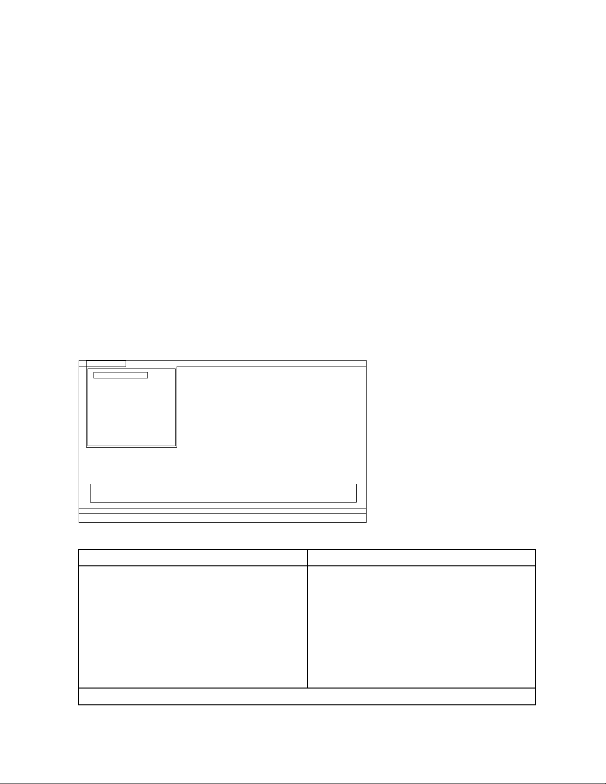
Diagnostics
Run Normal Test
Run Quick Test
CPU/Coprocessor
Systemboard
System Memory
Video Adapter
Fixed Disks
Diskette Drives
Other Devices
Communication
Interactive Tests Hardware Info Utility Quit F1=Help
PC-DOCTOR 2.0 Copyright 2008 PC-Doctor, Inc. All Rights Reserved.
Use the cursor keys and ESC to move in menus. Press ENTER to select.
Wireless LAN
fromaUSBattachedopticaldrive.
Torunthetest,doasfollows:
1.Turnoffthecomputer.
2.Makesurethattheopticaldrivethatissupportedasastartupdeviceisinstalledtothecomputer.
3.Turnonthecomputer.Ifthecomputercannotbeturnedon,goto“Powersystemcheckout”onpage37,
andcheckthepowersources.Ifanerrorcodeisdisplayed,goto“Symptom-to-FRUindex”onpage45
forerrorcodedescriptionsandtroubleshootinghints.
4.WhentheThinkPadlogocomesup,immediatelypressF12toentertheBootMenu.
5.InsertthePC-DoctorCDintotheopticaldrive.
6.PresscursorkeystoselectAT APICDx(x:0,1,...)andthenpressEnter.
7.Followtheinstructionsonthescreen.
8.ThemainpanelofPC-Doctorappears.
9.SelectDiagnosticswiththearrowkeys,andpressEnter.
Note:Youcanselectanitemnotonlywiththearrowkeys,butalsowiththeT rackPoint
InsteadofpressingEnter,clicktheleftbutton.
Apull-downmenuappears.(Itsexactformdependsonthemodel.)
Note:PC-Doctormenudoesnotmeantheformalsupportdevicelist.Someunsupporteddevicenames
mayappearinthePC-Doctormenu.
Theoptionsonthetestmenuareasfollows:
DiagnosticsInteractiveTests
•RunNormalT est
•RunQuickT est
•CPU/Coprocessor
•SystemMemory
•Systemboard
•VideoAdapter
•FixedDisks
•DisketteDrives
•OtherDevices
•Communication
•WirelessLAN
Notes:
•Keyboard
•Video
•InternalSpeaker
•Mouse
•Diskette
•SystemLoad
•OpticalDriveTest
•IntelWLANRadioT est
®
pointer.
32HardwareMaintenanceManual
Page 39

DiagnosticsInteractiveTests
•IntheKeyboardtestinInteractiveTests,theFnkeyshouldbehelddownforatleast2seconds;otherwise,it
cannotbesensed.
•VideoAdaptertestsupportsonlytheLCDdisplayontheThinkPadNotebook.Ifyouhaveanexternalmonitor
attachedtoyourcomputer,detachitbeforerunningPC-DoctorforDOS.
•T otestDigitalSignatureChip,thesecuritychipmustbesettoActive.
10.Runtheapplicablefunctiontest.
11.Followtheinstructionsonthescreen.Ifthereisaproblem,PC-Doctorshowsmessagesdescribingit.
12.Toexitthetest,selectQuit—ExitDiag.Tocancelthetest,pressEsc.
Note:AfterrunningPC-Doctor,checkthetimeanddateonthesystemandresetthemiftheyareincorrect.
DetectingsysteminformationwithPC-Doctor
PC-Doctorcandetectthefollowingsysteminformation:
HardwareInfo
•SystemConguration
•MemoryContents
•PhysicalDiskDrives
•VGAInformation
•A TADriveInfo
•PCIInformation
•PNPISAInfo
•SMBIOSInfo
•VESALCDInfo
•HardwareEventsLog
Utility
•RunExternalT ests
•BenchmarkSystem
•DOSShell
•T echSupportForm
•BatteryRundown
•EraseDriveContents
•ViewPCDRHostLog
LenovoThinkVantageT oolbox
LenovoThinkVantageToolboxisadiagnosticprogramthatworksthroughtheWindowsoperatingsystem.
Itenablesyoutoviewsymptomsofcomputerproblemsandsolutionsforthem,andincludesautomatic
noticationwhenactionisrequired,computingassistance,advanceddiagnostics,anddiagnostichistory.
Notes:
•ThelatestLenovoThinkVantageToolboxisavailableatthefollowingWebsite:
http://web.lenovothinkvantagetoolbox.com/
•T oinstallthelatestLenovoThinkVantageToolboxonthecomputer,clickDownloadLenovoThinkVantage
Toolbox,andthenfollowtheinstructionsontheWebsite.
Torunthisprogram,doasfollows:
Windows7:
WhiletheWindowsoperatingsystemisrunning,presstheThinkVantagebutton.
Tostartthisprogram,dothefollowing:
Chapter3.Generalcheckout33
Page 40

•ClickStart➙ControlPanel➙SystemandSecurity➙Lenovo–SystemHealthandDiagnostics.
WindowsVista
®
andWindowsXP:
ClickStart➙AllPrograms➙ThinkVantage➙LenovoThinkVantageToolbox
Followtheinstructionsonthescreen.LenovoThinkVantageT oolboxalsohasproblemdeterminationaids
thatdeterminesoftwareandusageproblems.
Foradditionalinformationaboutthisprogram,seetheHelpfortheprogram.
FRUtests
ThefollowingtableshowsthetestforeachFRU.
Table1.FRUtests
FRUApplicabletest
Systemboard1.Diagnostics➙CPU/Coprocessor
2.Diagnostics➙Systemboard
3.IfthedockingstationortheportreplicatorisattachedtotheThinkPadNotebook,
detachit.
4.Placethecomputeronahorizontalsurface,andrunDiagnostics➙ThinkPad
Devices➙HDDActiveProtectionTest.
Note:Donotapplyanyphysicalshocktothecomputerwhilethetestisrunning.
Power
LCDunit
Audio
SpeakerInteractiveTests➙InternalSpeaker
Keyboard
Harddiskdriveorsolidstate
drive
Diskettedrive1.Diagnostics➙DisketteDrives
Opticaldrive1.Diagnostics➙OtherDevices➙OpticalDrive
Memory
Diagnostics➙ThinkPadDevices➙ACAdapter,Battery1,orBattery2
1.Diagnostics➙VideoAdapter
2.InteractiveTests➙Video
EntertheThinkPadSetupandchangeSerialA T A(SATA)settingtoCompatibility,and
runDiagnostics➙OtherDevice➙ConexantAudio
Note:OnceAudiotestisdone,thenosoundisheardthistest.Inthiscase,turnoff
andturnonthecomputer.Then,runthistestagain.
1.Diagnostics➙Systemboard➙Keyboard
2.InteractiveTests➙Keyboard
EntertheThinkPadSetupandchangeSerialA T A(SATA)settingtoCompatibility,and
runDiagnostics➙FixedDisks
Youcanalsodiagnosethedrivewithoutstartinguptheoperatingsystem.Todiagnose
thedrivefromtheThinkPadSetup,doasfollows:
1.Removeanydiskettefromthediskettedrive,andthenturnoffthecomputer.
2.Turnonthecomputer.
3.Whilethemessage,“Tointerruptnormalstartup,presstheblueThinkVangate
button,”isdisplayedatthelowerleftofthescreen,pressF1toentertheThinkPad
Setup.
4.Usingcursorkeys,selectHDDdiagnosticprogram.Pressenter.
5.Usingcursorkeys,selectMainharddiskdriveorUltrabayharddiskdrive.
6.PressEntertostartthediagnosticprogram.
2.InteractiveTests➙Diskette
2.InteractiveTests➙OpticalDriveTest
1.IftwoDIMMsareinstalled,removeoneofthemandrunDiagnostics➙System
Memory.
2.Iftheproblemdoesnotrecur,returntheDIMMtoitsplace,removetheotherone,
andrunthetestagain.
34HardwareMaintenanceManual
Page 41

Table1.FRUtests(continued)
FRUApplicabletest
TrackPointorpointing
device
TouchPad
IftheTrackPointdoesnotwork,checkthecongurationasspeciedintheThinkPad
Setup.IftheT rackPointisdisabled,selectAutomatictoenableit.
AfteryouusetheT rackPoint,thepointermaydriftonthescreenforashorttime.This
driftcanoccurwhenaslight,steadypressureisappliedtotheTrackPointpointer.
Thissymptomisnotahardwareproblem.Ifthepointerstopsafterashorttime,no
serviceactionisnecessary.
IfenablingtheTrackPointdoesnotcorrecttheproblem,continuewiththefollowing:
•InteractiveT ests➙Mouse
IftheTouchPaddoesnotwork,checkthecongurationasspeciedintheThinkPad
Setup.IftheTouchPadisdisabled,selectAutomatictoenableit.Ifenablingthe
TouchPaddoesnotcorrecttheproblem,continuewiththefollowing:
•InteractiveT ests➙Mouse
SystemsupportingtheLenovodiagnosticsprograms
ThesectionprovidesinformationaboutThinkPadcomputersthatsupporttheLenovodiagnosticsprograms.
Somedescriptionsmightnotapplytoyourparticularcomputer.
TheLenovodiagnosticsprogramsincludefollowing:
•LenovoSolutionCenter
•Quicktestprograms
•UEFIdiagnosticprogram
•Bootablediagnosticprograms
LenovoSolutionCenter
TheLenovoSolutionCenterprogramenablesyoutotroubleshootandresolvecomputerproblems.It
combinesdiagnostictests,systeminformationcollection,securitystatus,andsupportinformation,along
withhintsandtipsformaximumsystemperformance.
Note:TheLenovoSolutionCenterprogramisavailableonlyonmodelspreinstalledwiththeWindows7
operatingsystem.Italsocanbedownloadedfromhttp://www.lenovo.com/diags.
ToruntheLenovoSolutionCenterprogram,clickStart➙ControlPanel➙SystemandSecurity➙Lenovo
-SystemHealthandDiagnostics,andthenfollowtheinstructionsonthescreen.
Foradditionalinformationaboutthisprogram,seethehelpinformationsystem.
Quicktestprograms
LenovoHardDriveQuickTestandLenovoMemoryQuickT estaretwoquicktestprogramsthatenableyou
totroubleshootandresolvecomputerinternalstorageandmemoryproblems.
Notes:
•IfthecomputeryouareservicingisnotinstalledwiththeLenovoSolutionCenterprogram,youcan
downloadthequicktestprogramsfromtheLenovoSupportWebsite.
•ThetwoprogramsareapplicabletocomputersinstalledwiththeWindows7,WindowsXP,Windows
Server2003,orWindowsServer2008operatingsystem.
Chapter3.Generalcheckout35
Page 42

Todownloadandinstallaquicktestprogram,gotohttp://www.lenovo.com/diags,andfollowtheinstructions
ontheWebsite.
Torunaquicktestusingthedownloadedprogram,dothefollowing:
1.GototheC:\SWTOOLS\ldiagfolder.
2.Double-clickthegui_lsc_lite.exele.
3.WhentheUserAccountControlwindowopens,clickY es.
4.Selectthedeviceclasstobetested.
5.Selectthedevicestobetested.
6.Selecttheteststobeperformed.
7.Followtheinstructionsonthescreentostartthetest.Whenaproblemisdetected,information
messageswillbedisplayed.Refertothemessagestotroubleshoottheproblem.
UEFIdiagnosticprogram
AUEFIdiagnosticprogramispreinstalledonthecomputer.Itenablesyoutotestmemoryandinternal
storageproblems,viewsysteminformation,andcheckandrecoverbadsectorsoninternalstoragedevices.
ToruntheUEFIdiagnosticprogram,dothefollowing:
1.Turnonthecomputer.Ifthecomputercannotbeturnedon,goto“Powersystemcheckout”onpage37,
andcheckthepowersources.Ifanerrorcodeisdisplayed,goto“Symptom-to-FRUindex”onpage45
forerrorcodedescriptionsandtroubleshootinghints.
2.WhentheThinkPadlogoisdisplayed,repeatedlypressandreleasetheF12key.WhentheBootMenu
windowopens,releasetheF12key.
3.PresstheTabkeytoswitchtotheApplicationMenuwindow.
4.UsethearrowkeystoselectLenovoDiagnosticsandthenpressEnter.ThemainscreenoftheUEFI
diagnosticprogramisdisplayed.
5.Followtheinstructionsonthescreentousethediagnosticprogram.
Theoptionsonthemainscreenareasfollows:
TestsTools
•QuickMemoryT est
•QuickStorageDeviceTest
•ExitApplication
•SystemInformation
•RecoverBadSectorsT ool
Bootablediagnosticprograms
IfthecomputeryouareservicingisnotinstalledwiththeUEFIdiagnosticprogram,youcandownloada
bootablediagnosticprogramfromtheLenovoSupportWebsite.Thebootablediagnosticprogramsenable
youtotestcomputermemoryandinternalstoragedevices,viewsysteminformation,andcheckandrecover
theinternalstoragedevices.T ousethebootablediagnosticprograms,youcancreateabootablediagnostic
mediumonaUSBdeviceorCD.
Tocreateabootablediagnosticmedium,dothefollowing:
1.Gotohttp://www.lenovo.com/diags.
2.ClickLenovoBootableDiagnostics.
3.FollowtheinstructionsontheWebsitetocreateabootablediagnosticmediumonaUSBdeviceorCD.
Tousethediagnosticmediumyouhavecreated,dooneofthefollowing:
36HardwareMaintenanceManual
Page 43

•IfyouhavecreatedthebootablediagnosticmediumonaUSBdevice,dothefollowing:
1.AttachtheUSBdevicetothecomputer.
2.Turnonthecomputer.Ifthecomputercannotbeturnedon,goto“Powersystemcheckout”onpage
,andcheckthepowersources.Ifanerrorcodeisdisplayed,goto“Symptom-to-FRUindex”on
37
page45forerrorcodedescriptionsandtroubleshootinghints.
3.WhentheThinkPadlogoisdisplayed,repeatedlypressandreleasetheF12key.WhentheBoot
Menuwindowopens,releasetheF12key.
4.UsethearrowkeystoselectUSBHDDandthenpressEnter.Thediagnosticprogramwillbe
launchedautomatically.
5.Followtheinstructionsonthescreentousethediagnosticprogram.
•IfyouhavecreatedthebootablediagnosticmediumonaCD,dothefollowing:
1.Turnonthecomputer.Ifthecomputercannotbeturnedon,goto“Powersystemcheckout”onpage
37,andcheckthepowersources.Ifanerrorcodeisdisplayed,goto“Symptom-to-FRUindex”on
page45forerrorcodedescriptionsandtroubleshootinghints.
2.InserttheCDintotheopticaldrive.
3.Restartthecomputer.
4.WhentheThinkPadlogoisdisplayed,repeatedlypressandreleasetheF12key.WhentheBoot
Menuwindowopens,releasetheF12key.
5.UsethearrowkeystoselectA T APICDx(x:0,1,...)andthenpressEnter.Thediagnosticprogram
willbelaunchedautomatically.
6.Followtheinstructionsonthescreentousethediagnosticprogram.
Powersystemcheckout
Toverifyasymptom,dothefollowing:
1.Turnoffthecomputer.
2.Removethebatterypack.
3.Connecttheacadapter.
4.Checkthatpowerissuppliedwhenyouturnonthecomputer.
5.Turnoffthecomputer.
6.Disconnecttheacadapterandinstallthechargedbatterypack.
7.Checkthatthebatterypacksuppliespowerwhenyouturnonthecomputer.
Ifyoususpectapowerproblem,seetheappropriateoneofthefollowingpowersupplycheckouts:
•“Checkingtheacpoweradapter”onpage37
•“Checkingoperationalcharging”onpage38
•“Checkingthebatterypack”onpage38
•“Checkingthebackupbattery”onpage39
Checkingtheacpoweradapter
Ifyoucomputerfailsonlywhentheacpoweradapterisused,usetheinstructionsinthistopic.
•Ifthepowerproblemoccursonlywhenthedockingstationortheportreplicatorisused,replacethe
dockingstationortheportreplicator.
•Ifthepower-onindicatordoesnotturnon,checkthepowercordoftheacadapterforcorrectcontinuity
andinstallation.
•Ifthecomputerdoesnotchargeduringoperation,goto“Checkingoperationalcharging”onpage38.
Tochecktheacadapter,dothefollowing:
1.Unplugtheacadaptercablefromthecomputer.
Chapter3.Generalcheckout37
Page 44

2.Measuretheoutputvoltageattheplugoftheacadaptercable.Seethefollowinggure:
1
2
3
(20V)
Pin
1+20
20
3
Voltage(Vdc)
Ground
Note:Outputvoltageacrosspin2oftheacpoweradaptermightdifferfromtheoneyouareservicing.
3.Ifthevoltageisnotcorrect,replacetheacadapter.
4.Ifthevoltageisacceptable,dothefollowing:
a.Replacethesystemboard.
b.IftheproblempersistsandyoursystemisinstalledwiththePCdoctorforDOS,goto“FRUtests”
onpage34.
Note:Noisefromtheacadapterdoesnotalwaysindicateadefect.
Checkingoperationalcharging
Tocheckwhetherthebatterychargesproperlyduringoperation,useadischargedbatterypackorabattery
packthathaslessthan50%ofthetotalpowerremainingwheninstalledinthecomputer.
Performoperationalcharging.Ifthebatterystatusindicatororicondoesnotturnon,removethebattery
packandletitreturntoroomtemperature.Reinstallthebatterypack.Ifthechargeindicatororiconstilldoes
notturnon,replacethebatterypack.
Ifthechargeindicatorstilldoesnotturnon,replacethesystemboard.Thenreinstallthebatterypack.Ifitis
stillnotcharged,gotothenextsection.
Checkingthebatterypack
BatterychargingdoesnotstartuntilthePowerManagerBatteryGaugeshowsthatlessthan96%ofthe
totalpowerremains;underthisconditionthebatterypackcanchargeto100%ofitscapacity.Thisprotects
thebatterypackfrombeingoverchargedorfromhavingashortenedlife.
Tocheckyourbattery,moveyourcursortothePowerManagerBatteryGaugeiconintheicontrayofthe
Windowstaskbarandwaitforamoment(butdonotclick),andthepercentageofbatterypowerremaining
isdisplayed.Togetdetailedinformationaboutthebattery,double-clickthePowerManagerBattery
Gaugeicon.
Note:Ifthebatterypackbecomeshot,itmaynotbeabletocharge.Removeitfromthecomputerandleave
itatroomtemperatureforawhile.Afteritcoolsdown,reinstallandrechargeit.
Tocheckthebatterypack,dothefollowing:
1.Poweroffthecomputer.
2.Removethebatterypackandmeasurethevoltagebetweenbatteryterminals1(+)and7(-).Seethe
followinggure:
38HardwareMaintenanceManual
Page 45

Terminal
1(+)
2(+)
3
4
5
6(-)
7(-)
1+0to+12.6
7
Voltage(Vdc)
Ground(-)
3.Ifthevoltageislessthan+11.0Vdc,thebatterypackhasbeendischarged.
Note:Rechargingwilltakeatleast3hours,eveniftheindicatordoesnotturnon.
Ifthevoltageisstilllessthan+11.0Vdcafterrecharging,replacethebattery.
4.Ifthevoltageismorethan+11.0Vdc,measuretheresistancebetweenbatteryterminals5and7.
Theresistancemustbe4to30KΩ.Iftheresistanceisnotcorrect,replacethebatterypack.Ifthe
resistanceiscorrect,replacethesystemboard.
Checkingthebackupbattery
Dothefollowing:
1.Poweroffthecomputer,andunplugtheacadapterfromit.
2.Turnthecomputerupsidedown.
3.Removethebatterypack(see“1010Batterypack”onpage66).
4.Removethebackupbattery(see“1120Backupbattery”onpage85).
5.Measurethevoltageofthebackupbattery.Seethefollowinggure.
Wire
Red+2.5to+3.2
Black
Voltage(Vdc)
Ground
•Ifthevoltageiscorrect,replacethesystemboard.
•Ifthevoltageisnotcorrect,replacethebackupbattery.
•Ifthebackupbatterydischargesquicklyafterreplacement,replacethesystemboard.
Chapter3.Generalcheckout39
Page 46

40HardwareMaintenanceManual
Page 47

Chapter4.Relatedserviceinformation
Thischapterpresentsfollowinginformation:
•“RestoringthefactorycontentsbyusingRecoveryDiscSet”onpage41
•“Passwords”onpage42
•“Powermanagement”onpage44
•“Symptom-to-FRUindex”onpage45
ServiceWebsite:
Whenthelatestmaintenancedisketteandthesystemprogramservicediskettebecomeavailable,they
willbepostedonhttp://www.lenovo.com/support.
RestoringthefactorycontentsbyusingRecoveryDiscSet
Whentheharddiskdrive(HDD)orsolidstatedrive(SSD)isreplacedbecauseofafailure,noproductrecovery
programisonthenewdrive.Inthiscase,youmustusetheRecoveryDiscSetforthecomputer.Orderthe
RecoveryDiscSetandthedriveatthesametimesothatyoucanrecoverthenewdrivewiththepre-installed
softwarewhentheyarrive.Forinformationonwhichdiscstoorder,see“Recoverydiscs”onpage155
TherecoverydiscsetconsistsoftheuserinstructionsandthefollowingsetofDVDstorestorethecomputer
totheoriginalfactoryconguration.
•OperatingSystemRecoveryDisc(onedisc):ThisdiscrestorestheMicrosoftWindowsoperatingsystem.
Usethisdisctostarttherecoveryprocess.
•ApplicationsandDriversRecoveryDisc(oneormorediscs):Thisdiscrestoresthepreinstalled
applicationsanddriversonthecomputer.
•SupplementalRecoveryDisc:Thisdisccontainsadditionalcontent,suchasupdatestothesoftwarethat
waspreinstalledonthecomputer.NotallrecoverydiscsetscomewithaSupplementalRecoveryDisc.
.
Notes:
•Y oumusthaveaDVDdrivetousetherecoverydiscs.IfyoudonothaveaninternalDVDdrive,you
canuseanexternalUSBDVDdrive.
•Duringtherecoveryprocess,alldataonthedrivewillbedeleted.Ifpossible,copyanyimportantdata
orpersonallesthatyouwanttokeepontoremovablemediaoranetworkdrivebeforeyoustartthe
recoveryprocess.
Torestorethecomputertotheoriginalfactorycongurationusingtherecoverydiscset,dothefollowing:
Note:Recoverycantakeonetotwohourstocomplete.Thelengthoftimedependsonthemethodyouuse.
Ifyouuserecoverydiscs,therecoveryprocesswilltakeabouttwohours.
1.MaketheCD/DVDdrivetherststartupdeviceinthestartupsequenceusingthefollowingprocedure:
a.PressandholddowntheF1key,andthenturnonthecomputer.Whenthelogoscreenisdisplayed
orifyouhearrepeatingbeeps,releasetheF1key.TheThinkPadSetupprogramopens.
b.UsethearrowkeystoselectStartup➙Boot.
c.SelecttheCD/DVDdriveasthe1stBootDevice.
2.InserttheOperatingSystemRecoveryDiscintotheDVDdrive.
3.PressF10tosavetheThinkPadSetupcongurationchanges.Followtheinstructionsonthescreento
begintherecoveryprocess.
4.SelectyourlanguageandclickNext.
©CopyrightLenovo2011,2012
41
Page 48

5.Readthelicense.Ifyouagreewiththetermsandconditions,selectIacceptthesetermsand
conditionsandthenclickNext.Ifyoudonotagreewiththetermsandconditions,followthe
instructionsonthescreen.
6.ClickYesinthedisplayedwindowtobegintheoperatingsystemrecoveryprocess.
7.InserttheApplicationsandDriversRecoveryDiscwhenpromptedandthenclickOKtobeginthe
applicationsanddriversrecoveryprocess.
8.IfyouhaveaSupplementalRecoveryDisc,insertitwhenpromptedandclickYes.Ifyoudonothavea
SupplementalRecoveryDisc,clickNo.
9.Whenallofthedatahasbeencopiedfromthelastdiscinthesetandhasbeenprocessed,removethe
discandrestartthecomputer.
Note:Therestoftherecoveryprocessisfullyautomatedandnoactionisrequiredbyyou.The
computerwillrestartintotheMicrosoftWindowsdesktopseveraltimesandyoumightexperience
periodswhennoactivityisapparentonthescreenforseveralminutesatatime.Thisisnormal.
10.Whentherecoveryprocessiscomplete,theSetUpWindowsscreenisdisplayed.Followthe
instructionsonthescreentocompletetheWindowssetup.
11.AfteryouhavecompletedtheWindowssetup,youmightwanttorestoretheoriginalstartupsequence.
StarttheThinkPadSetupprogramandthenpressF9torestorethedefaultsettings.PressF10tosave
changesandexittheThinkPadSetupprogram.
Note:Afterrestoringadrivetothefactorydefaultsettings,youmightneedtoreinstallsomedevicedrivers.
Passwords
AsmanyasthreepasswordsmaybeneededforanyThinkPadNotebook:thepower-onpassword(POP),
thehard-diskpassword(HDP),andthesupervisorpassword(SVP).
Ifanyofthesepasswordshasbeenset,apromptforitappearsonthescreenwheneverthecomputeris
turnedon.Thecomputerdoesnotstartuntilthepasswordisentered.
Note:IfonlyanSVPisinstalled,thepasswordpromptdoesnotappearwhentheoperatingsystemisbooted.
Power-onpassword
Apower-onpassword(POP)protectsthesystemfrombeingpoweredonbyanunauthorizedperson.The
passwordmustbeenteredbeforeanoperatingsystemcanbebooted.ForhowtoremovethePOP ,see
“Howtoremovethepower-onpassword”onpage43
.
Hard-diskpassword
Therearetwohard-diskpasswords(HDPs):
•UserHDP—fortheuser
•MasterHDP—forthesystemadministrator,whocanuseittogetaccesstotheharddiskeveniftheuser
haschangedtheuserHDP
Note:TherearetwomodesfortheHDP:UseronlyandMaster+User.TheMaster+Usermoderequires
twoHDPs;thesystemadministratorentersbothinthesameoperation.Thesystemadministratorthen
providestheuserHDPtothesystemuser.
Attention:IftheuserHDPhasbeenforgotten,checkwhetheramasterHDPhasbeenset.Ifithas,itcanbe
usedforaccesstotheharddiskdrive.IfnomasterHDPisavailable,neitherLenovonorLenovoauthorized
servicetechniciansprovideanyservicestoreseteithertheuserorthemasterHDP ,ortorecoverdatafrom
theharddiskdrive.Theharddiskdrivecanbereplacedforascheduledfee.
42HardwareMaintenanceManual
Page 49

ForhowtoremovethePOP,see“Howtoremovethehard-diskpassword”onpage43.
Supervisorpassword
Asupervisorpassword(SVP)protectsthesysteminformationstoredintheThinkPadSetupprogram.
TheusermustentertheSVPinordertogetaccesstotheThinkPadSetupprogramandchangethe
systemconguration.
Attention:IftheSVPhasbeenforgottenandcannotbemadeavailabletotheservicetechnician,thereisno
serviceproceduretoresetthepassword.Thesystemboardmustbereplacedforascheduledfee.
Howtoremovethepower-onpassword
(A)IfnoSVPhasbeenset:
ToremoveaPOPthatyouhaveforgotten,dothefollowing:
1.Turnoffthecomputer.
2.Removethebatterypack.Forhowtoremovethebatterypack,see“1010Batterypack”onpage66.
3.Removethebackupbattery.Forhowtoremovethebackupbattery,see“1120Backupbattery”on
page85.
4.TurnonthecomputerandwaituntilthePOSTends.AfterthePOSTends,thepasswordpromptdoes
notappear.ThePOPhasbeenremoved.
5.Reinstallthebackupbatteryandthebatterypack.
(B)IfanSVPhasbeensetandisknownbytheservicetechnician:
1.Turnonthecomputer.
2.WhentheThinkPadlogoisdisplayed,immediatelypressF1.
3.TypethesupervisorpasswordtoentertheThinkPadSetupprogram.
4.SelectSecurity,usingthecursordirectionalkeystomovethemenu.
5.SelectPassword.
6.SelectPower-OnPassword.
7.TypethecurrentsupervisorpasswordintheEnterCurrentPasswordeld.thenleavetheEnter
NewPasswordeldblank,andpressEntertwice.
8.Inthe“Changeshavebeensaved”window,pressEnter.
9.PressF10;then,intheSetupconrmationwindow,selectY es.
Howtoremovethehard-diskpassword
Attention:IfUseronlymodeisselectedandtheuserHDPhasbeenforgottenandcannotbemade
availabletotheservicetechnician,neitherLenovonorLenovoauthorizedservicetechniciansprovideany
servicestoresettheuserHDPsortorecoverdatafromtheharddiskdrive.Theharddiskdrivecanbe
replacedforascheduledfee.
ToremoveauserHDPthathasbeenforgotten,whentheSVPandthemasterHDPareknown,dothe
following:
1.Turnonthecomputer.
2.WhentheThinkPadlogocomesup,immediatelypressF1toentertheThinkPadSetupprogram.When
Power-OnPasswordiconisappearingonthescreen,enterthePower-OnPassword.
3.SelectSecurity,usingthecursordirectionalkeystomovethemenu.
4.SelectPassword.
5.SelectHard-diskxpassword,wherexistheletteroftheharddiskdrive.Apop-upwindowopens.
Chapter4.Relatedserviceinformation43
Page 50

6.SelectMasterHDP.
7.TypethecurrentmasterHDPintheEnterCurrentPasswordeld.thenleavetheEnterNewPassword
eldblank,andpressEntertwice.
8.PressF10tosavechangesandexittheThinkPadSetupprogram.Theuserharddiskpasswordandthe
masterharddiskpasswordhavebeenremoved.
Powermanagement
Toreducepowerconsumption,thecomputerhasthreepowermanagementmodes:screenblank,sleep
(standbyinWindowsXP),andhibernation.
Screenblankmode
Ifthetimesetonthe“Turnoffmonitor”timerintheoperatingsystemexpires,theLCDbacklightturnsoff.
Toputthecomputerintoscreenblankmode,doasfollows:
1.PressFn+F3.Apanelforselectingapowerplan(inWindowsXP,powerscheme)appears.
2.SelectPoweroffdisplay(keepcurrentpowerplan)(inWindowsXP ,keepcurrentpowerscheme).
Toendscreenblankmodeandresumenormaloperation,pressanykey.
Sleep(standby)mode
Whenthecomputerenterssleep(standby)mode,thefollowingeventsoccurinadditiontowhatoccurs
inscreenblankmode:
•TheLCDispoweredoff.
•Theharddiskdriveispoweredoff.
•Themicroprocessorstops.
Toentersleep(standby)mode,pressFn+F4.
Note:YoucanchangetheactionoftheFn+F4keycombinationbychangingthesettingsinPowerManager.
Incertaincircumstances,thecomputergoesintosleep(standby)modeautomatically:
•Ifa“suspendtime”hasbeensetonthetimer,andtheuserdoesnotdoanyoperationwiththekeyboard,
theTrackPoint,theharddisk,theparallelconnector,orthediskettedrivewithinthattime.
•Ifthebatteryindicatorblinksorange,indicatingthatthebatterypowerislow.
Note:Evenifyoudonotsetthelow-batteryalarm,thechargeindicatornotiesyouwhenthebatteryislow,
andthenthecomputerentersthepower-savingmodeautomatically.
Tocausethecomputertoreturnfromsleep(standby)modeandresumeoperation,dooneofthefollowing:
•PresstheFnkey.
•OpentheLCDcover.
•T urnonthepowerswitch.
Also,ineitherofthefollowingevents,thecomputerautomaticallyreturnsfromsleep(standby)modeand
resumesoperation:
•Theringindicator(RI)issignaledbyaserialdeviceoraPCCarddevice.
•Thetimesetontheresumetimerelapses.
Note:Thecomputerdoesnotacceptanyinputimmediatelyafteritenterssleep(standby)mode.Waita
fewsecondsbeforetakinganyactiontoreenteroperationmode.
44HardwareMaintenanceManual
Page 51

Hibernationmode
Inhibernationmode,thefollowingoccurs:
•Thesystemstatus,RAM,VRAM,andsetupdataarestoredontheharddisk.
•Thesystemispoweredoff.
Note:Ifthecomputerentersthehibernationmodewhileitisdockedtothedockingstation,donotundockit
beforeresumingnormaloperation.Ifyoudoundockitandthentrytoresumenormaloperation,youwillget
anerrormessage,andyouwillhavetorestartthesystem.
Tocausethecomputertoenterhibernationmode,doanyofthefollowing:
•PressFn+F12.
•IfyouareusingtheAPMoperatingsystemandhavesetthemodetoPowerswitchmode[Hibernation],
turnoffthepowerswitch.
•IfyouareusingtheACPIoperatingsystemandhavedenedoneofthefollowingactionsastheeventthat
causesthesystemtogointohibernationmode,performthataction.
–Closingthelid.
–Pressingthepowerbutton.
–PressingFn+F4.
Also,thecomputergoesintohibernationmodeautomaticallyineitherofthefollowingconditions:
•Ifa“hibernationtime”hasbeensetonthetimer,andiftheuserdoesnotdoanyoperationwiththe
keyboard,theT rackPoint,theharddiskdrive,theparallelconnector,orthediskettedrivewithinthattime.
•Ifthetimerconditionsaresatisedinsuspendmode.
•IfyouareusingtheAPMoperatingsystemandhavesetthemodetoHibernatewhenbatterybecomes
low,andthebatterychargebecomescriticallylow.
Whenthepoweristurnedon,thecomputerreturnsfromhibernationmodeandresumesoperation.The
hibernationleinthebootrecordontheharddiskdriveisread,andsystemstatusisrestoredfromthe
harddiskdrive.
Symptom-to-FRUindex
Thissectioncontainsfollowinginformation:
•“Numericerrorcodes”onpage46
•“Errormessages”onpage47
•“Beepsymptoms”onpage48
•“No-beepsymptoms”onpage48
•“LCD-relatedsymptoms”onpage49
•“Intermittentproblems”onpage49
•“Undeterminedproblems”onpage49
Thesymptom-to-FRUindexinthissectionlistssymptomsanderrorsandtheirpossiblecauses.Themost
likelycauseislistedrst,inboldfacetype.
Note:DotheFRUreplacementorotheractionsinthesequenceshowninthecolumnheaded“FRUor
action,insequence.”IfreplacingaFRUdoesnotsolvetheproblem,puttheoriginalpartbackinthe
computer.DonotreplaceanondefectiveFRU.
Thisindexcanalsohelpyoudetermine,duringregularservicing,whatFRUsarelikelytoneedtobe
replacednext.
Chapter4.Relatedserviceinformation45
Page 52

AnumericerrorisdisplayedforeacherrordetectedinPOSTorsystemoperation.Inthedisplays,ncan
beanynumber.
Ifnonumericcodeisdisplayed,checkthenarrativedescriptionsofsymptoms.Ifthesymptomisnot
describedthere,goto“Intermittentproblems”onpage49.
Note:ForadevicenotsupportedbydiagnosticcodesintheThinkPadNotebooks,seethemanualfor
thatdevice.
Numericerrorcodes
Table2.Numericerrorcodes
Symptomorerror
0177
BadSVPdata,stopPOSTtask—Thechecksumofthe
supervisorpasswordintheEEPROMisnotcorrect.
0182
BadCRCofSecuritySettingsinEEPROM.EnterThinkPad
Setup.
0183
BadCRCofSecuritySettingsinEFIVariable.Enter
ThinkPadSetup.
0187
EAIAdataaccesserror—TheaccesstoEEPROMisfailed.
0188
InvalidRFIDSerializationInformationArea.
0189
InvalidRFIDcongurationinformationarea—The
EEPROMchecksumisnotcorrect.
0190
Criticallow-batteryerror
0191
SystemSecurity—InvalidRemoteChangerequested.
0199
SystemSecurity—Securitypasswordretrycount
exceeded.
0251
SystemCMOSchecksumbad—Defaultconguration
used.
0271
Real-timeclockerror.Checkdateandtimesettings.
1802
Unauthorizednetworkcardispluggedin—Turnoffand
removetheminiPCInetworkcard.
1820
Morethanoneexternalngerprintreaderisattached.
Poweroffandremoveallbutthereaderthatyousetup
withinyourmainoperatingsystem.
FRUoraction,insequence
Systemboard
1.RunThinkPadSetup.PressF9,andEntertoload
thedefaultsetting.Thensavethecurrentsetting
bypressingF10.
2.Systemboard
Systemboard
Systemboard
Systemboard
1.Chargethebatterypack.
2.Batterypack
1.RunThinkPadSetup,andthensavecurrent
settingbypressingF10.
2.Systemboard
1.RunThinkPadSetup,andthensavethecurrent
settingbypressingF10.
2.Systemboard
1.Chargethebackupbatteryformorethan8hours
byconnectingtheacadapter.
2.ReplacethebackupbatteryandrunThinkPadSetup
toresetthetimeanddate.
RunThinkPadSetuptoresetthetimeanddate.
1.RemoveMiniPCInetworkcard.
2.Systemboard
Removeallbutthereaderthatyousetupforthe
authentication.
46HardwareMaintenanceManual
Page 53

Table2.Numericerrorcodes(continued)
Symptomorerror
2000
HardDriveActiveProtectionsensordiagnosticsfailed.
Press<Esc>tocontinue.Press<F1>toenterSETUP
2100
DetectionerroronHDD0(MainHDD)
2101
DetectionerroronHDD1(UltrabayHDD)
2102
DetectionerroronHDD2(MiniSATA)
2110
ReaderroronHDD0(MainHDD)
2111
ReaderroronHDD1(UltrabayHDD)
2112
ReaderroronHDD2(MiniSAT A)
2200
MachineTypeandSerialNumberareinvalid.
2201
MachineUUIDisinvalid.
FRUoraction,insequence
1.Undockdockingstationorportreplicatorifitis
attachedtotheThinkPadNotebook.
2.PlacetheNotebookonahorizontalsurface.Donot
applyanyphysicalshocktothecomputer.
3.RunDiagnostics➙ThinkPadDevices➙HDD
ActiveProtectionT est.
1.Reseattheharddiskdrive.
2.Mainharddiskdrive
3.Systemboard
1.Reseattheharddiskdrive.
2.Ultrabayharddiskdrive
3.Systemboard
1.ReseattheMiniSATAdevice.
2.MiniSATAdevice
3.Systemboard
1.Reseattheharddiskdrive.
2.Mainharddiskdrive
3.Systemboard
1.Reseattheharddiskdrive.
2.Ultrabayharddiskdrive
3.Systemboard
1.ReseattheMiniSATAdevice.
2.MiniSATAdevice
3.Systemboard
Systemboard
Systemboard
Errormessages
Table3.Errormessages
Symptomorerror
Fanerror.1.Fan
Thermalsensingerror.
Thissystemdoesnotsupportbatteriesthatarenot
genuineLenovo-madeorauthorized.Thesystemwill
continuetoboot,butmaynotchargeunauthorized
batteries.
Attention:Lenovohasnoresponsibilityforthe
performanceorsafetyofunauthorizedbatteries,and
providesnowarrantiesforfailuresordamagearisingout
oftheiruse.
TheconnectedACadapterhasalowerwattagethanthe
recommendedmodelwhichwasshippedwiththesystem.
Thiswillincreasethetimetochargethebattery,and
systemperformancewillbeadjustedtomatchthe
availablepower.
FRUoraction,insequence
2.Thermalgrease
3.Systemboard
Systemboard
Replacethebattery.
Chargetheacpoweradapter.
Chapter4.Relatedserviceinformation47
Page 54

Table3.Errormessages(continued)
Symptomorerror
PleaseconnecttheACadapterwhichwasshippedwith
thesystemforbestsystemperformance.
PresstheESCkeytocontinue.Dockingstationis
removedoritsIDisdifferent,pressF3topoweroff
systemandrestorecorrectdockingstation,pressF4to
normalboot.
Beepsymptoms
Table4.Beepsymptoms
FRUoraction,insequence
Symptomorerror
Onebeepandablank,unreadable,orashingLCD.1.ReseattheLCDconnector
Onelongandtwoshortbeeps,andablankorunreadable
LCD.
Twoshortbeepswitherrorcodes.
Twoshortbeepsandablankscreen.
Twoormorebeeps,oracontinuousbeep.Operating
systemstartssuccessfully.
Threeshortbeeps,pause,threemoreshortbeeps,and
oneshortbeep.
Oneshortbeep,pause,threeshortbeeps,pause,three
moreshortbeeps,andoneshortbeep.
Onlythecursorappears.
Fourcyclesoffourshortbeepsandablankscreen.
Fiveshortbeepsandablankscreen.
FRUoraction,insequence
2.LCDassembly
3.ExternalCRT
4.Systemboard
1.Systemboard
2.LCDassembly
3.DIMM
POSTerror.See“Numericerrorcodes”onpage46.
1.Systemboard
2.DIMM
Ifamini-PCIEthernetcardisinstalled,conrmthatAlert
OnLAN2inThinkPadSetupisdisabled.
1.DIMM
2.Systemboard
Reinstalltheoperatingsystem.
Systemboard(securitychip)
Systemboard
No-beepsymptoms
Table5.No-beepsymptoms
Symptomorerror
Nobeep,power-onindicatoron,LCDblank,andno
POST.
Nobeep,power-onindicatoron,andLCDblankduring
POST.
Thepower-onpasswordpromptappears.Apower-onpasswordorasupervisorpasswordisset.
Thehard-diskpasswordpromptappears.Ahard-diskpasswordisset.T ypethepasswordand
48HardwareMaintenanceManual
FRUoraction,insequence
1.Makesurethateveryconnectorisconnected
tightlyandcorrectly.
2.DIMM
3.Systemboard
1.ReseatDIMM.
2.Systemboard
TypethepasswordandpressEnter.
pressEnter.
Page 55

LCD-relatedsymptoms
Important:TheTFTLCDforthenotebookcomputercontainsmanythin-lmtransistors(TFTs).The
presenceofasmallnumberofdotsthataremissing,discolored,oralwayslightedischaracteristicofTFT
LCDtechnology,butexcessivepixelproblemscancauseviewingconcerns.IftheLCDyouareservicinghas
twoorlessvisibledefectivepixels,itshouldnotbeconsideredfaulty.However,iftheLCDhasthreeormore
visibledefectivepixels,itwillbedeemedasdefectivebyLenovoanditshouldbereplaced.
Notes:
•ThispolicyappliestoallThinkPadNotebookspurchasedon1January,2008orlater.
•LenovowillnotprovidereplacementiftheLCDiswithinspecicationaswecannotguaranteethatany
replacementLCDwillhavezeropixeldefects.
•OnepixelconsistsofR,G,Bsub-pixels.
Table6.LCD-relatedsymptoms
Symptomorerror
Nobeep,power-onindicatoron,andablankLCDduring
POST.
•LCDbacklightnotworking
•LCDtoodark
•LCDbrightnesscannotbeadjusted.
•LCDcontrastcannotbeadjusted.
•LCDscreenunreadable
•Charactersmissingpixels
•Screenabnormal
•Wrongcolordisplayed
HorizontalorverticallinesdisplayedonLCDLCDassembly
FRUoraction,insequence
Systemboard
1.ReseattheLCDconnectors.
2.LCDassembly
3.Systemboard
1.Seeimportantnotefor“LCD-relatedsymptoms.”
2.ReseatallLCDconnectors.
3.LCDassembly
4.Systemboard
Intermittentproblems
Intermittentsystemhangproblemscanbeduetoavarietyofcausesthathavenothingtodowithahardware
defect,suchascosmicradiation,electrostaticdischarge,orsoftwareerrors.FRUreplacementshouldbe
consideredonlywhenaproblemrecurs.
Whenanalyzinganintermittentproblem,dothefollowing:
1.Runthediagnostictestforthesystemboardinloopmodeatleast10times.
2.Foreachtest,dooneofthefollowing:
•Ifnoerrorisdetected,donotreplaceanyFRUs.
•Ifanyerrorisdetected,replacetheFRUshownbytheFRUcode.Rerunthetesttoverifythat
nomoreerrorsexist.
Undeterminedproblems
Ifthediagnostictestsdidnotidentifytheadapterordevicethathasfailed,ifwrongdevicesareinstalled,
orifthesystemsimplyisnotoperating,followtheseprocedurestoisolatethefailingFRU(donotisolate
FRUsthathavenodefects).
Verifythatallattacheddevicesaresupportedbythecomputer.
Verifythatthepowersupplybeingusedatthetimeofthefailureisoperatingcorrectly.(See
checkout”onpage37.)
Chapter4.Relatedserviceinformation49
“Powersystem
Page 56

1.Turnoffthecomputer.
2.VisuallycheckeachFRUfordamage.ReplaceanydamagedFRU.
3.Removeordisconnectallofthefollowingdevices:
a.Non- ThinkPaddevices
b.Devicesattachedtothedockingstationortheportreplicator
c.Printer,mouse,andotherexternaldevices
d.Batterypack
e.Harddiskdrive
f.Externaldiskettedriveoropticaldrive
g.DIMM
h.Opticaldiskordisketteintheinternaldrive
i.PCCards
4.Turnonthecomputer.
5.Determinewhethertheproblemhasbeensolved.
6.Iftheproblemdoesnotrecur,reconnecttheremoveddevicesoneatatimeuntilyoundthefailingFRU.
7.Iftheproblemremains,replacethefollowingFRUsoneatatime(donotreplaceanondefectiveFRU):
a.Systemboard
b.LCDassembly
50HardwareMaintenanceManual
Page 57

Chapter5.InstallingandconguringRAID
Thischaptercontainsthefollowingtopics:
•“SupportedRAIDlevels”onpage51
•“ConguringthesystemUEFIBIOStoenableembeddedSATARAIDfunctionality”onpage51
•“CreatingRAIDvolumes”onpage52
•“DeletingRAIDvolumes”onpage52
Note:WhentheUEFIBIOSwasformattedorthesystemboardwasreplacedintheRAID-supportedmodels,
RAIDisenabledbydefault.
ImportantnoticesforsettingRAID:
BeforeyouinstallandcongureRAID,checkthecurrentRAIDsettingonthecomputeryouareservicing.
ThisproductsupportseitherRAID0orRAID1.ConrmtheRAIDsettinginformationprovidedbythe
customeratrst,thenproceedwiththeinstallation.
TosupportRAID0orRAID1,thecomputersyouareservicingmustbeequippedwithtworives.
SupportedRAIDlevels
ThefollowingRAIDlevelsaresupportedonRAID-supportedmodels:
RAID0-Stripeddiskarray
Betterperformanceandnofaulttolerance.
RAID1-Mirroreddiskarray
Improvedreadperformanceand100%redundancy.
ConguringthesystemUEFIBIOStoenableembeddedSATARAID
functionality
Note:ForRAID-supportedmodels,theembeddedSA T ARAIDfunctionalityisenabledbydefault.
ToconguretheUEFIBIOSforRAID,dothefollowing:
1.PressF1toentertheThinkPadSetupprogram.
2.SelectCong.
3.SelectSerialATA(SA T A).
4.SelectSATAControllerModeOption,andthenthefollowingoptionswillbedisplayed:
•Compatibility
•AHCI
•RAID
5.SelectRAID.
6.PressF10tosavechangesandexit.
Attention:AfteryouhaveenabledtheSATARAIDfunctionality,reinstalltheoperatingsystembeforetaking
anyfurtherRAID-relatedaction.
©CopyrightLenovo2011,2012
51
Page 58

CreatingRAIDvolumes
ThistopicdescribeshowtousetheIntelRapidStorageT echnologyoptionROMcongurationutilityto
createRAIDvolumes.
TocreateRAIDvolumes,dothefollowing:
1.Turnonthecomputer.
2.WhenamessagePress<Ctrl-I>toenterCongurationUtilityisdisplayed,pressCtr+I.
3.OntheIntelRapidStorageT echnologyoptionROMscreen,selectCreateRAIDVolume,andthen
pressEnter.
4.FollowtheinstructionsonthescreentoselecttheRAIDlevelandllinotherelds.
5.SelectCreateVolume.Whenadialogboxisdisplayed,pressY.
Attention:AlltheexistingdatastoredontheselecteddrivewillbeerasedwhiletheRAIDvolume
isbeingcreated.
6.Exitthecongurationutility.
DeletingRAIDvolumes
ThistopicdescribeshowtousetheIntelRapidStorageT echnologyoptionROMcongurationutilityto
deleteRAIDvolumes.
TodeleteaRAIDvolume,dothefollowing:
1.Turnonthecomputer.
2.WhenamessagePress<Ctrl-I>toenterCongurationUtilityisdisplayed,pressCtr+I.
3.OntheIntelRapidStorageT echnologyoptionROMscreen,selecttheRAIDvolumetobedeleted,
andthenpressDelete.
4.Whenadialogboxisdisplayed,pressYtoconrmthedeletionoftheselectedRAIDvolume.
5.Exitthecongurationutility.
52HardwareMaintenanceManual
Page 59

Chapter6.Statusindicators
7
8
3 4 5 621
9
12 11 10
Thischapterpresentsthesystemstatusindicatorsthatshowthestatusofthecomputer.
©CopyrightLenovo2011,2012
53
Page 60

Table7.Statusindicators
R
IndicatorMeaning
1
Speakermute
Orange:
Thespeakerisonmute.Tosetthe
speakersonmuteorunmute,pressthe
speakermutebutton.
2
Microphonemute
Orange:
Themicrophoneisonmute.Noneofthe
recordingdevicesisavailablewhilethe
microphonemuteisonbydefault.
3
WirelessLAN,
WirelessWAN,or
WiMAXstatus
Green:ThewirelessLANfeature(theIEEE
802.11b/gstandard,802.11a/b/g,
or802.11n),wirelessWANfeature,or
WiMaxfeatureison,andtheradiolink
isreadyforuse.
Blinkinggreen:Dataisbeingtransmitted.
4
Bluetoothwireless
status
Green:
TheBluetoothwirelessfeatureison,and
theradiolinkisreadyforuse.
Blinkinggreen:Dataisbeingtransmitted.
5
Deviceaccess
Green:
Dataisbeingreadfromorwrittentothe
harddiskdrive,thediskettedrive,orthe
driveintheSerialUltrabay™Enhanced
device.Whenthisindicatorison,donot
putthecomputerintosleep(standby)
modeorturnoffthecomputer.
Note:Donotmovethesystemwhilethegreendeviceaccesslightison.Sudden
physicalshockcouldcausedriveerrors.
6
Poweron
Green:
Thecomputerisonandreadytouse.
Thisindicatorstayslitaroundthe
power-onbuttonwheneverthecomputer
isonandisnotinsleep(standby)mode.
7
SerialUltrabay
Enhanceddevice
status
Green:ASerialUltrabayEnhanceddeviceis
installedandinuse.
Blinkinggreen:
ASerialUltrabayEnhanceddeviceisin
theprocessofbeingdetached.
Turnoff:
ASerialUltrabayEnhanceddeviceis
readytobeattachedordetached.
8
Fingerprintreader
status
Green:
Blinkinggreen:
Thengerprintreaderisreadytoswipe.
Thengerprintisbeingauthenticatedor
hasbeenauthenticated.
Blinkingorange:
Thengerprintcouldnotbe
authenticated.
54HardwareMaintenanceManual
Page 61
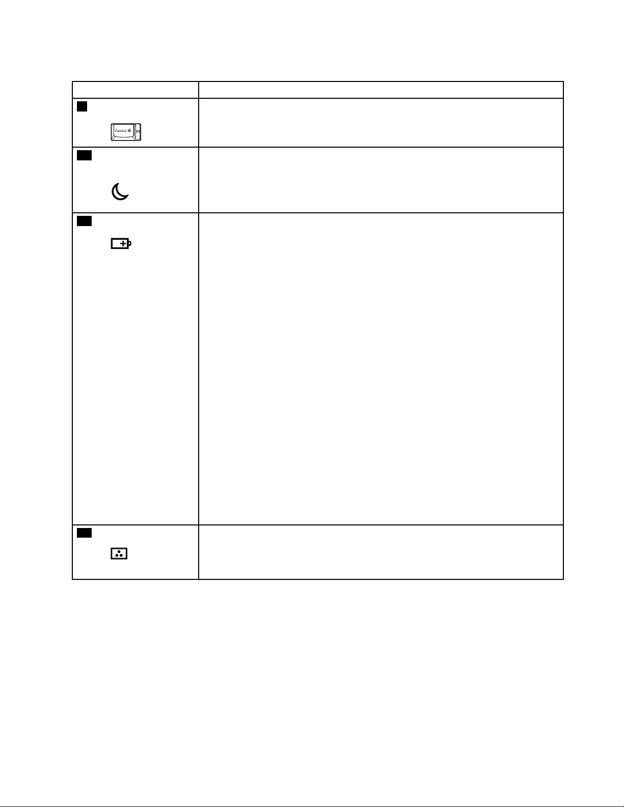
Table7.Statusindicators(continued)
IndicatorMeaning
9
Capslock
Green:CapsLockmodeisenabled.Toenable
ordisableCapsLockmode,pressthe
CapsLockkey.
10
Sleep(standbyfor
WindowsXP)status
Green:Thecomputerisinsleep(standby)mode.
Blinkinggreen:
Thecomputerisenteringsleep(standby)
modeorhibernationmode,oris
resumingnormaloperation.
11
Batterystatus
Green:
Orange:
Thebatteryhasmorethan20%charge.
Thebatteryhasbetween5%and20%
charge.
Fastblinkingorange:
Thebatteryhaslessthan5%charge.
Note:Thebatterymaybecharging.
Slowblinkingorange:
Thebatteryisbeingcharged.Whenit
reaches20%,theblinkingcolorchanges
togreen.
Slowblinkinggreen:
Thebatteryhasbetween20%and80%
charge,andchargingiscontinuing.
Whenthebatteryreaches80%charge,
blinkingstops,butthechargingmay
continueuntilthebatteryis100%
charged.
Note:Ifthecomputerisoperating
onbatterypower,thebatterystatus
indicatordoesnotworkwhilethe
computeristurnedofforisinsleep
(standby)modeorhibernationmode.
Quickblinkingorange:
Anerrorhasbeenoccurredinthebattery.
Thebatterystatusindicatorisoff:Thebatterypackofthecomputeris
detached.
12
Colorsensorstatus
Green:Calibrationiscomplete.Whenthelidis
opened,theindicatorturnsoff.
Blinkinggreen:Displaycolorsarebeingcalibrated.
Chapter6.Statusindicators55
Page 62

56HardwareMaintenanceManual
Page 63

Chapter7.Fnkeycombinations
ThefollowingtableshowsthefunctionofeachcombinationofFnwithafunctionkey.
Table8.Fnkeycombinations
KeycombinationDescription
Fn+F1Reserved.
Fn+F2Lockthecomputer.
Fn+F3
Fn+F4
Fn+F5
Selectapowerplan(inWindowsXP ,powerscheme)thathasbeencreatedbythePower
Managerprogram,oradjustthepowerlevelbyusingtheslidercontrol.Whenyoupressthis
combination,apanelforselectingapowerplan(powerscheme)isdisplayed.
Notes:
1.TousetheFn+F3keycombination,youmusthavetheThinkPadPowerManagement
driverinstalledonthecomputer.
2.IfyouhaveloggedonwithanadministratoruserIDinWindowsXP,andyoupressFn+F3,
thewindowforselectingapowerschemewillbedisplayed.Ifyouhaveloggedonwith
anotheruserIDinWindowsXP,andyoupressFn+F3,thewindowwillnotbedisplayed.
3.YoucannotturnoffthecomputerdisplaybypressingFn+F3.
Putthecomputerinsleep(standby)mode.Toreturntonormaloperation,presstheFnkey
only,withoutpressingafunctionkey.
Note:
Tousethiscombinationofthekeys,ThinkPadPowerManagementdevicedrivermust
havebeeninstalledonthecomputer.
Ifyouwanttousethecombinationtoputthecomputerintohibernationmodeor
do-nothingmode(inWindowsXP ,shutthecomputerdownorshowthepanelforturning
offthecomputer),changethesettingsinthePowerManager.
Enableordisablethebuilt-inwirelessnetworkingfeaturesandtheBluetoothfeatures.Ifyou
pressFn+F5,alistofwirelessfeaturesisdisplayed.Y oucanquicklychangethepowerstate
ofeachfeatureinthelist.
Notes:IfyouwanttouseFn+F5toenableordisablethewirelessfeatures,thefollowing
devicedriversmustbeinstalledonthecomputerbeforehand:
•ThinkPadPowerManagementdriver
•OnScreenDisplayUtility
•Wirelessdevicedrivers
Fn+F6
Fn+F7Applyapresentationschemedirectly,withnoneedtostartthePresentationDirectorprogram.
©CopyrightLenovo2011,2012
Changethecameraandaudiosettings.WhenyoupressFn+F6,thecameraandaudiosetting
windowisopenedandthecamerapreviewisturnedon.
Note:Thecamerasettingsareaonlyappearsifthecomputerhasanintegratedcamera.
TodisablethisfunctionandusetheFn+F7keycombinationforswitchingadisplayoutput
location,startPresentationDirector,andchangethesettings.
Note:IfthecomputerisanWindows7model,itdoesnotsupportpresentationschemes,
howevertheFn+F7combinationmightstillbeusedtoswitchdisplayoutputlocation.
57
Page 64

Table8.Fnkeycombinations(continued)
KeycombinationDescription
Fn+F7ForWindows7:
Switchbetweenthecomputerdisplayandanexternalmonitor.Windowswillshowthese
displayoptions:
•Computerdisplayonly(LCD)
•Computerdisplayandexternalmonitor(sameimage)
•Computerdisplayandexternalmonitor(extendeddesktopfunction)
•Externalmonitoronly
Note:T oswitchbetweenthecomputerdisplayandanexternalmonitor,theWin+Pkey
combinationisalsoavailable.
ForWindowsVista:
Switchbetweenthecomputerdisplayandanexternalmonitor.Ifanexternalmonitoris
attached,computeroutputisdisplayedinthefollowingthreepatternsbyturns:
•Externalmonitor(CRTdisplay)
•Computerdisplayandexternalmonitor(LCD+CRTdisplay)
•Computerdisplay(LCD)
Notes:
•Thisfunctionisnotsupportedifdifferentdesktopimagesaredisplayedonthecomputer
displayandtheexternalmonitor(theextenddesktopfunction).
•ThisfunctiondoesnotworkwhileaDVDmovieoravideoclipisplaying.
Toenablethisfunction,startthePresentationDirectorprogram,andchangethesettings.
Note:MultipleuserscanlogontoasingleoperatingsystembyusingdifferentuserIDs.
Eachuserneedstodothefollowing:
ClickStart➙AllPrograms➙ThinkVantage➙PresentationDirector,andchangethe
Fn+F7settings.
Fn+F8
ChangethesettingsoftheUltraNav
®
pointingdevice.
Fn+F9Reserved.
Fn+F10Reserved.
Fn+F11Reserved.
Fn+F12Putthecomputerintohibernationmode.T oreturntonormaloperation,pressthepower
buttonforlessthanfourseconds.
Note:TouseFn+F12forhibernation,youmusthavetheThinkPadPowerManagementdriver
installedonthecomputer.
Fn+PgUp
TurntheThinkLightlightonoroff.
Note:ThisfunctionissupportedonlyontheThinkPadnotebookcomputersthathavethe
ThinkLightlight.TheonoroffstatusoftheThinkLighlightisdisplayedonthescreenfor
afewsecondswhenyoupressFn+PgUp.
Fn+HomeThecomputerdisplaybecomesbrighter.
Fn+EndThecomputerdisplaybecomesdimmer.
Fn+SpacebarEnabletheFullScreenMagnierfunction.
Fn+PrtScHavethesamefunctionastheSysRqkey.
Fn+ScrLk
Enableordisablethenumerickeypad.Theindicatorofnumericlockwillbedisplayedon
thescreen.
58HardwareMaintenanceManual
Page 65

Table8.Fnkeycombinations(continued)
KeycombinationDescription
Fn+Pause
Fn+cursorkeys
HavethesamefunctionastheBreakkey.
ThesekeycombinationsworkwithWindowsMediaPlayer.Theyhavethefollowingfunctions:
•Fn+downarrowkey:PlayorPause
•Fn+uparrowkey:Stop
•Fn+rightarrowkey:NextT rack
•Fn+leftarrowkey:PreviousTrack
Chapter7.Fnkeycombinations59
Page 66

60HardwareMaintenanceManual
Page 67

Chapter8.FRUreplacementnotices
ExternalCRUstatementtocustomers:
Someproblemswithyourproductcanberesolvedwithareplacementpartyoucaninstallyourself,called
a“CustomerReplaceableUnit”or“CRU.”SomeCRUsaredesignatedasSelf-serviceCRUsandothers
aredesignatedasOptional-serviceCRUs.InstallationofSelf-serviceCRUsisyourresponsibility;youmay
requestthatLenovoinstallsanOptional-serviceCRUaccordingtothewarrantyserviceforyourproduct.
WhereyouareinstallingtheCRU,LenovowillshiptheCRUtoyou.CRUinformationandreplacement
instructionsareshippedwithyourproductandareavailablefromLenovoatanytimeuponrequest.Y oumay
ndalistofCRUsinthepublicationsthatshipwithyourproductorathttp://www.lenovo.com/CRUs.Y ou
mayberequiredtoreturnthedefectivepartthatisreplacedbytheCRU.Whenreturnisrequired:(1)return
instructions,aprepaidshippinglabel,andacontainerwillbeincludedwiththereplacementCRU;and(2)you
maybechargedforthereplacementCRUifLenovodoesnotreceivethedefectivepartwithinthirty(30)days
ofyourreceiptofthereplacementCRU.SeeyourLenovoLimitedWarrantydocumentationforfulldetails.
Thischapterpresentsnoticesrelatedtoremovingandreplacingparts.Readthischaptercarefullybefore
replacinganyFRU.
Screwnotices
Loosescrewscancauseareliabilityproblem.IntheThinkPadnotebookcomputer,thisproblemisaddressed
withspecialnylon-coatedscrewsthathavethefollowingcharacteristics:
•Theymaintaintightconnections.
•Theydonoteasilycomeloose,evenwithshockorvibration.
•Theyarehardertotighten.
Dothefollowingwhenyouservicethismachine:
•Keepthescrewkitinyourtoolbag.Forthepartnumberofthescrewkit,see“Miscellaneousparts”on
page152
•Itisrecommendedtousenewscrews.
•Itisrecommendedtouseeachscrewonlyonce.
•Useatorquescrewdriverifyouhaveone.
Tightenscrewsasfollows:
•Plastictoplastic
Turnanadditional90degreesafterthescrewheadtouchesthesurfaceoftheplasticpart:
•Logiccardtoplastic
Turnanadditional180degreesafterthescrewheadtouchesthesurfaceofthelogiccard:
.
©CopyrightLenovo2011,2012
61
Page 68

•T orquedriver
Ifyouhaveatorquedriver,refertotheT orquecolumninthescrewinformationtableforeachstep.
–Makesurethatyouusethecorrectscrew.Itisrecommendedtousenewscrewsforreplacements.
–Ifyouhaveatorquescrewdriver,tightenallscrewsrmlytothetorquespeciedinthescrew
informationtableforeachstep.
–Ensuretorquescrewdriversarecalibratedcorrectlyfollowingcountryspecications.
Retainingserialnumbers
Thissectionincludesthefollowingdescriptions:
•“Restoringtheserialnumberofthesystemunit”onpage62
•“RetainingtheUUID”onpage63
•“ReadingorwritingtheECAinformation”onpage63
Restoringtheserialnumberofthesystemunit
Whenthecomputerwasmanufactured,theEEPROMonthesystemboardwasloadedwiththeserial
numbersofthesystemandallmajorcomponents.Thesenumbersneedtoremainthesamethroughout
thelifeofthecomputer.
Ifyoureplacethesystemboard,youmustrestoretheserialnumberofthesystemunittoitsoriginalvalue.
Beforereplacingthesystemboard,savetheoriginalserialnumberbydoingthefollowing:
1.InstalltheLENOVOThinkPadHardwareMaintenanceDisketteVersion1.76orlater,andrestartthe
computer.
2.Fromthemainmenu,select1.SetSystemIdentication.
3.Select2.ReadS/NdatafromEEPROM.
Theserialnumberofeachdeviceinyourcomputerisdisplayed;theserialnumberofthesystemunitis
listedasfollows:
•20:Serialnumber
Writedownthatnumber.
Note:Theserialnumberofthesystemunitisalsowrittenonthelabelattachedtothebottomofthecomputer.
Afteryouhavereplacedthesystemboard,restoretheserialnumberbydoingthefollowing:
1.InstalltheLENOVOThinkPadHardwareMaintenanceDisketteVersion1.76orlaterandrestartthe
computer.
2.Fromthemainmenu,select1.SetSystemIdentication.
3.Select1.AddS/NdatafromEEPROM.Followtheinstructionsonthescreen.
IftheMTMandProductIDnumbersdifferfromeachotherontherearlabel,usewhatisshownforthe
ProductIDeld.Seeexamplebelow:
62HardwareMaintenanceManual
Page 69

MTMonrearlabel:
TTTT-CTOS/NSSSSSSS
ProductIDonrearlabel:
TTTT-MMM(UsethisnumberwhensettingSerialNumber)
Intheexample,theSerialNumbertobeinputis'1STTTTMMMSSSSSSS'.
RetainingtheUUID
TheUniversallyUniqueIdentier(UUID)isa128-bitnumberuniquelyassignedtoyourcomputerat
productionandstoredintheEEPROMofyoursystemboard.
ThealgorithmthatgeneratesthenumberisdesignedtoprovideuniqueIDsuntiltheyearA.D.3400.Notwo
computersintheworldhavethesamenumber.
Whenyoureplacethesystemboard,youmustsettheUUIDonthenewsystemboardasfollows:
1.InstalltheLENOVOThinkPadHardwareMaintenanceDisketteVersion1.76orlater,andrestartthe
computer.
2.Fromthemainmenu,select4.AssignUUID.AnewUUIDiscreatedandwritten.IfavalidUUIDalready
exists,itisnotoverwritten.
ReadingorwritingtheECAinformation
InformationonEngineeringChangeAnnouncements(ECA)arestoredintheEEPROMofthesystemboard.
TheelectronicstorageofthisinformationsimpliestheproceduretocheckiftheECAhasbeenpreviously
appliedtoamachine.ThemachinedoesnotneedtobedisassembledtocheckfortheECAapplication.
TocheckwhatECAshavebeenpreviouslyappliedtothemachine,usetheECAInformationRead/Write
functionontheLENOVOThinkPadHardwareMaintenanceDisketteVersion1.76orlater.
1.InserttheLENOVOThinkPadHardwareMaintenanceDisketteVersion1.76orlater,andrestartthe
computer.
2.Fromthemainmenu,select6.SetECAInformation.
3.ToreadECAinformation,select2.ReadECA/reworknumberfromEEPROMandfollowthe
instruction.
4.Toreadboxbuilddate,select5.ReadboxbuilddatefromEEPROM,andfollowtheinstructionon
thescreen.
AfteranECAhasbeenappliedtothemachine,theEEPROMmustbeupdatedtoreecttheECA's
application.UsetheLENOVOThinkPadHardwareMaintenanceDisketteVersion1.76orlatertoupdatethe
EEPROM.
Note:OnlytheECAnumberisstoredintheEEPROM.ThemachinetypeoftheECAisassumedbethesame
asthemachinetypeofthemachinethathadtheECAappliedtoit.
1.InserttheLENOVOThinkPadHardwareMaintenanceDisketteVersion1.76orlater,andrestartthe
computer.
2.Fromthemainmenu,select6.SetECAInformation.
3.TowriteECAinformation,select1.WriteECA/reworknumberfromEEPROM,andfollowthe
instruction.
4.Towriteboxbuilddate,select4.WriteboxbuilddatefromEEPROM,andfollowtheinstructionon
thescreen.
Chapter8.FRUreplacementnotices63
Page 70

Ifthesystemboardisbeingreplaced,trytoreadtheECAinformationfromtheoldsystemboardandtransfer
theinformationtothenewsystem.Ifthesystemboardisinoperable,thiswillnotbepossible.
64HardwareMaintenanceManual
Page 71

Chapter9.RemovingandreplacingaFRU
ExternalCRUstatementtocustomers:
Someproblemswithyourproductcanberesolvedwithareplacementpartyoucaninstallyourself,called
a“CustomerReplaceableUnit”or“CRU.”SomeCRUsaredesignatedasSelf-serviceCRUsandothers
aredesignatedasOptional-serviceCRUs.InstallationofSelf-serviceCRUsisyourresponsibility;youmay
requestthatLenovoinstallsanOptional-serviceCRUaccordingtothewarrantyserviceforyourproduct.
WhereyouareinstallingtheCRU,LenovowillshiptheCRUtoyou.CRUinformationandreplacement
instructionsareshippedwithyourproductandareavailablefromLenovoatanytimeuponrequest.Y oumay
ndalistofCRUsinthepublicationsthatshipwithyourproductorathttp://www.lenovo.com/CRUs.Y ou
mayberequiredtoreturnthedefectivepartthatisreplacedbytheCRU.Whenreturnisrequired:(1)return
instructions,aprepaidshippinglabel,andacontainerwillbeincludedwiththereplacementCRU;and(2)you
maybechargedforthereplacementCRUifLenovodoesnotreceivethedefectivepartwithinthirty(30)days
ofyourreceiptofthereplacementCRU.SeeyourLenovoLimitedWarrantydocumentationforfulldetails.
ThischapterpresentsdirectionsanddrawingsforuseinremovingandreplacingaFRU.Besuretoobserve
thefollowinggeneralrules:
1.Donottrytoserviceanycomputerunlessyouhavebeentrainedandcertied.Anuntrainedpersonruns
theriskofdamagingparts.
2.BeforereplacinganyFRU,reviewChapter8“FRUreplacementnotices”onpage61.
3.BeginbyremovinganyFRUsthathavetoberemovedbeforethefailingFRU.AnysuchFRUsarelisted
atthetopofthepage.Removethemintheorderinwhichtheyarelisted.
4.FollowthecorrectsequenceinthestepsforremovingtheFRU,asgiveninthedrawingsbythe
numbersinsquarecallouts.
5.WhenturningascrewtoreplaceaFRU,turnitinthedirectionasgivenbythearrowinthedrawing.
6.WhenremovingtheFRU,moveitinthedirectionasgivenbythearrowinthedrawing.
7.ToputthenewFRUinplace,reversetheremovalprocedureandfollowanynotesthatpertainto
replacement.Forinformationaboutconnectingandarranginginternalcables,seeChapter10
“Locations”onpage111.
8.WhenreplacingaFRU,usethecorrectscrewasshownintheprocedures.
DANGER
BeforeremovinganyFRU,turnoffthecomputer,unplugallpowercordsfromelectricaloutlets,
removethebatterypack,andthendisconnectanyinterconnectingcables.
Attention:AfterreplacingaFRU,donotturnonthecomputeruntilyouhavemadesurethatallscrews,
springs,andothersmallpartsareinplaceandnonearelooseinsidethecomputer.Verifythisbyshaking
thecomputergentlyandlisteningforrattlingsounds.Metallicpartsormetalakescancauseelectrical
shortcircuits.
Attention:Thesystemboardissensitiveto,andcanbedamagedby,electrostaticdischarge.Before
touchingit,establishpersonalgroundingbytouchingagroundpointwithonehandorbyusingan
electrostaticdischarge(ESD)strap(P/N6405959).
©CopyrightLenovo2011,2012
65
Page 72
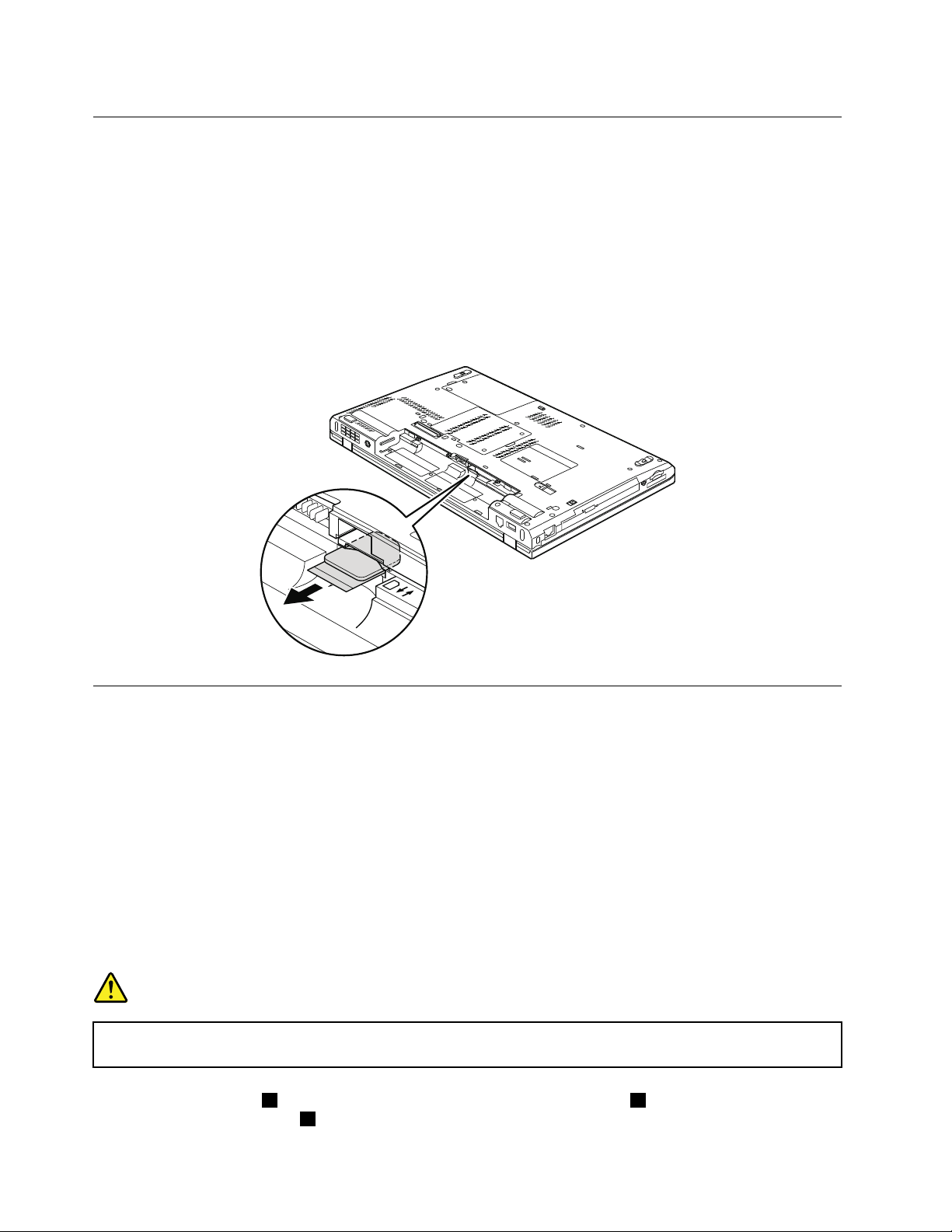
BeforeservicingThinkPadT520,T520i,andW520
RemovalstepsofSIMcard
SomemodelsoftheThinkPadT520,T520i,andW520youareservicingmighthavetheSIMcardthatthe
customerhasinstalled.
IfthecomputeryouareservicinghastheSIMcard,removeitbeforeyoustarttheservicing.
ToremovetheSIMcard,youneedtoremovethebatterypackrst.(See“1010Batterypack”onpage66.)
Afteryounishtheservicing,makesurethatyouinsertthecardbackintotheslotrmly.
1010Batterypack
Importantnoticeforreplacingabatterypack:
TheLenovoThinkVantageToolboxandLenovoSolutionCenter(inWindows7)haveanautomaticbattery
diagnosticthatdeterminesifthebatterypackisdefective.AbatterypackFRUshouldnotbereplacedunless
thisdiagnosticshowsthatthebatteryisdefective.
Theonlyexceptiontothisisifthebatterypackisphysicallydamagedoracustomerisreportingapossible
safetyissue.
IfThinkVantageToolboxorLenovoSolutionCenterisnotinstalledinthecomputer,thecustomershould
downloadthisprogrambeforeanon-physicallydamagedbatterypackisreplaced.Notethatthereplacement
ofaphysicallydamagedbatterypackisnotcoveredbythewarranty.
Removalstepsofbatterypack
DANGER
Useonlythebatteryspeciedinthepartslistforyourcomputer.Anyotherbatterycouldignite
orexplode.
Unlockthebatterylatch1.Holdingthebatterylatchintheunlockedposition2,removethebatterypackin
thedirectionshownbyarrow3.
66HardwareMaintenanceManual
Page 73
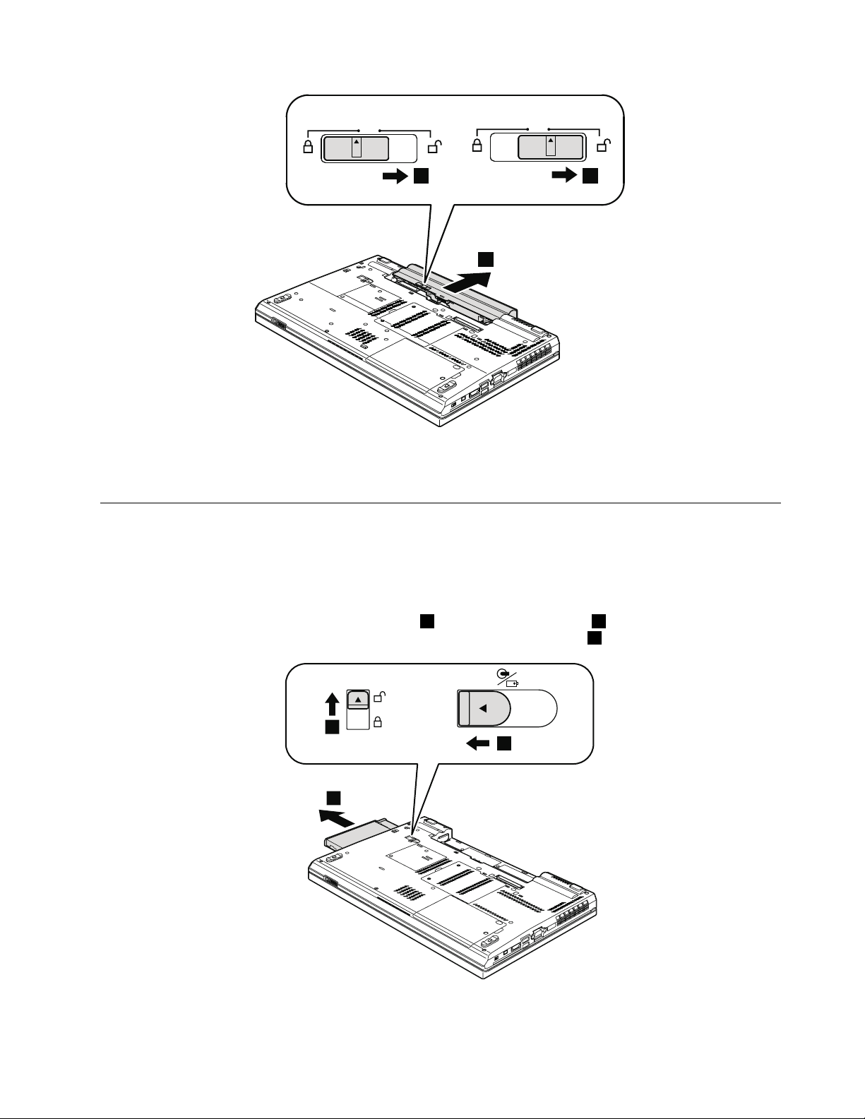
3
21
Wheninstalling:Installthebatterypackintheslot,andthenmakesurethatthebatterylatchisinthe
3
2
1
lockedposition.
1020SerialUltrabayEnhanceddeviceortravelbezel
Foraccess,removethisFRU:
•“1010Batterypack”onpage66
RemovalstepsofSerialUltrabayEnhanceddeviceortravelbezel
Holdingthebaylocklatchintheunlockedposition1,slidethebayejectlatch2,andthenpullouttheSerial
UltrabayEnhanceddeviceorthetravelbezelinthedirectionshownbyarrow3.
Chapter9.RemovingandreplacingaFRU67
Page 74

Note:ForRAIDmodels,thesecondharddiskdriveadaptercannotberemoveddirectlyasshowninthe
aboveillustrationuntilyouremovethescrewthatsecuresthesecondharddiskdriveadapter:
StepScrew(quantity)Color
NA
M3×5mm,at-head(1)
1030DIMMslotcover
Foraccess,removethisFRU:
•“1010Batterypack”onpage66
RemovalstepsofDIMMslotcover
Note:Loosenthescrews1,butdonotremovethem.
Torque
Black0.392Nm
(4kgf-cm)
68HardwareMaintenanceManual
Page 75

1
2
1040DIMM(bottomslot)
Foraccess,removetheseFRUsinorder:
•“1010Batterypack”onpage66
•“1030DIMMslotcover”onpage68
RemovalstepsofDIMM(bottomslot)
ForThinkPadT520andT520i:
Chapter9.RemovingandreplacingaFRU69
Page 76

1
1
2
ForThinkPadW520:
1
1
2
a b
70HardwareMaintenanceManual
Page 77

Notes:
2
1
•IfonlyoneDIMMisusedonthecomputeryouareservicing,thecardmustbeinstalledinSLOT-0a,
butnotinSLOT -2
•Ifthecomputeryouareservicingisadual-coreprocessormodel,adummyDIMMcardispreinstalledin
SLOT -2b.DonotreplacethedummyDIMMcardwithaSO-DIMM.
Wheninstalling:InsertthenotchedendoftheDIMMintothesocket.PresstheDIMMrmly,andpivotit
untilitsnapsintotheplace.Makesurethatitisrmlyxedintheslotanddoesnotmoveeasily.
b.
1050Harddiskdriveslotcover,harddiskdrive(HDD)andHDDrubber railsorsolidstatedrive(SSD)andstorageconverter
Foraccess,removethisFRU:
•“1010Batterypack”onpage66
Attention:
•Donotdropthedriveorapplyanyphysicalshocktoit.Thedriveissensitivetophysicalshock.
Improperhandlingcancausedamageandpermanentlossofdata.
•Beforeremovingthedrive,havetheusermakeabackupcopyofalltheinformationonitifpossible.
•Neverremovethedrivewhilethesystemisoperatingorisinsuspendmode.
Removalstepsofharddiskdriveslotcover,HDDandHDDrubberrailsorSSDandstorageconverter
Note:Loosenthescrew1,butdonotremoveit.
Chapter9.RemovingandreplacingaFRU71
Page 78

3
RemovalstepsofHDDandHDDrubberrails
4
4
4
4
RemovalstepsofSSDandSSDspacers
Wheninstalling:MakesurethattheSSDconnectororHDDconnectorisattachedrmly.
1060Keyboard
Foraccess,removetheseFRUsinorder:
•“1010Batterypack”onpage66
•“1030DIMMslotcover”onpage68
72HardwareMaintenanceManual
Page 79

Removalstepsofkeyboard
1
1
2
StepScrew(quantity)Color
1
M2×14mm,wafer-head,nylon-coated(2)
Black0.181Nm
Torque
(1.85kgf-cm)
1.Pushdownthekeyboardalittletowardthearrow2untilthefrontedgeofthekeyboardisdetached
fromthekeyboardbezel.
2.Liftthekeyboardalittleinthedirectionshownbyarrow3,andthendetachtheconnector4.
Chapter9.RemovingandreplacingaFRU73
Page 80
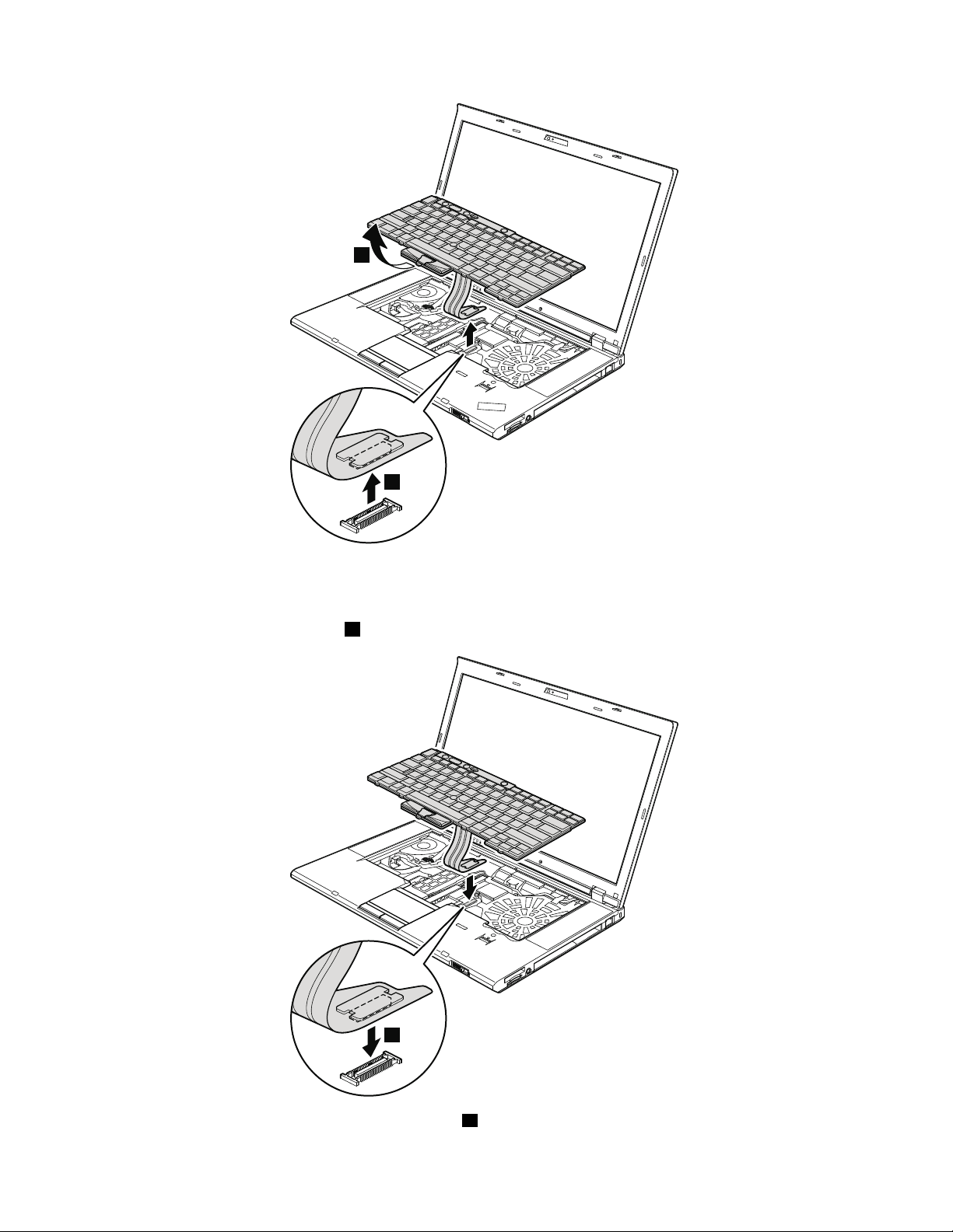
3
4
Installationstepsofkeyboard
1
Wheninstallingthekeyboard,doasfollows:
1.Attachthekeyboardconnector1.
2.Attachthekeyboardsothatthekeyboardedgesaareundertheframeasshowninthisgure.
74HardwareMaintenanceManual
Page 81

a
a
3.Gentlypressthekeyswithyourthumbsandtrytoslidethekeyboardtowardyou.
4.Makesurethatthefrontsideofthekeyboardbishousedrmly.
Chapter9.RemovingandreplacingaFRU75
Page 82
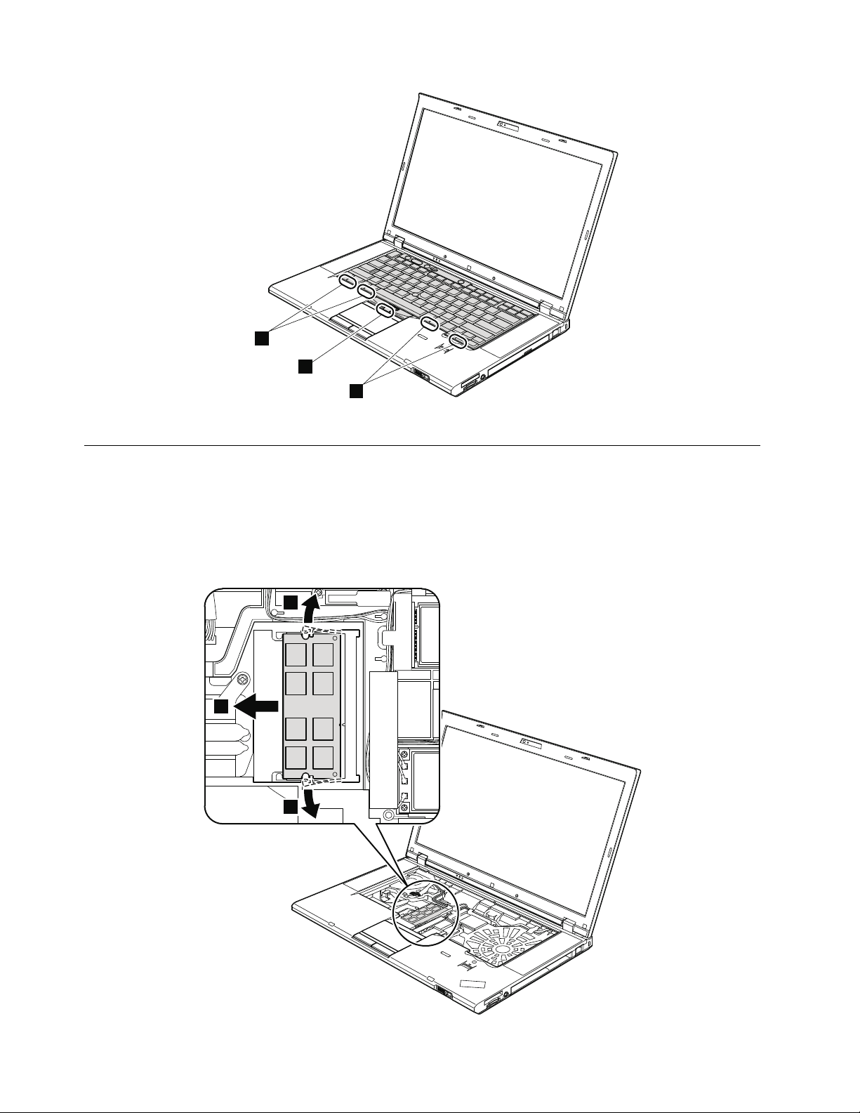
b
b
b
5.Securethekeyboardbytighteningthescrewsfromthebottomsideofthecomputer.
1
1
2
1070DIMM(upperslot)
Foraccess,removetheseFRUsinorder:
•“1010Batterypack”onpage66
•“1030DIMMslotcover”onpage68
•“1060Keyboard”onpage72
RemovalstepsofDIMM(upperslot)
76HardwareMaintenanceManual
Page 83
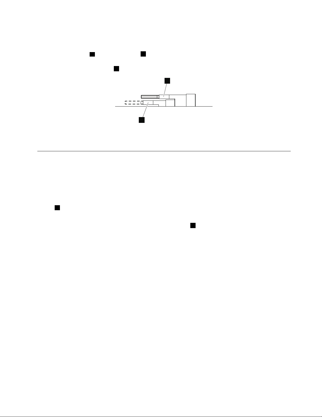
Notes:
a
b
•ForThinkPadW520,ifonlyoneDIMMisusedonthecomputeryouareservicing,thecardmustbe
installedinSLOT -0
a,butnotinSLOT -2b.
•ForThinkPadW520,ifthecomputeryouareservicingisadual-coreprocessormodel,adummyDIMM
cardispreinstalledinSLOT -2b.DonotreplacethedummyDIMMcardwithaSO-DIMM.
Wheninstalling:InsertthenotchedendoftheDIMMintothesocket.PresstheDIMMrmly,andpivotit
untilitsnapsintotheplace.Makesurethatitisrmlyxedintheslotanddoesnotmoveeasily.
1080PCIExpressMiniCardforwirelessLAN
Foraccess,removetheseFRUsinorder:
•“1010Batterypack”onpage66
•“1030DIMMslotcover”onpage68
•“1060Keyboard”onpage72
RemovalstepsofPCIExpressMiniCardforwirelessLAN
Instep1,unplugthejacksbyusingtheantennaRFconnectorremovaltool(P/N:08K7159)orpickthe
connectorswithyourngersandgentlyunplugthemindirectionofthearrow.
Note:Somemodelsmighthaveonlytwoantennacablesinstep1.
Chapter9.RemovingandreplacingaFRU77
Page 84
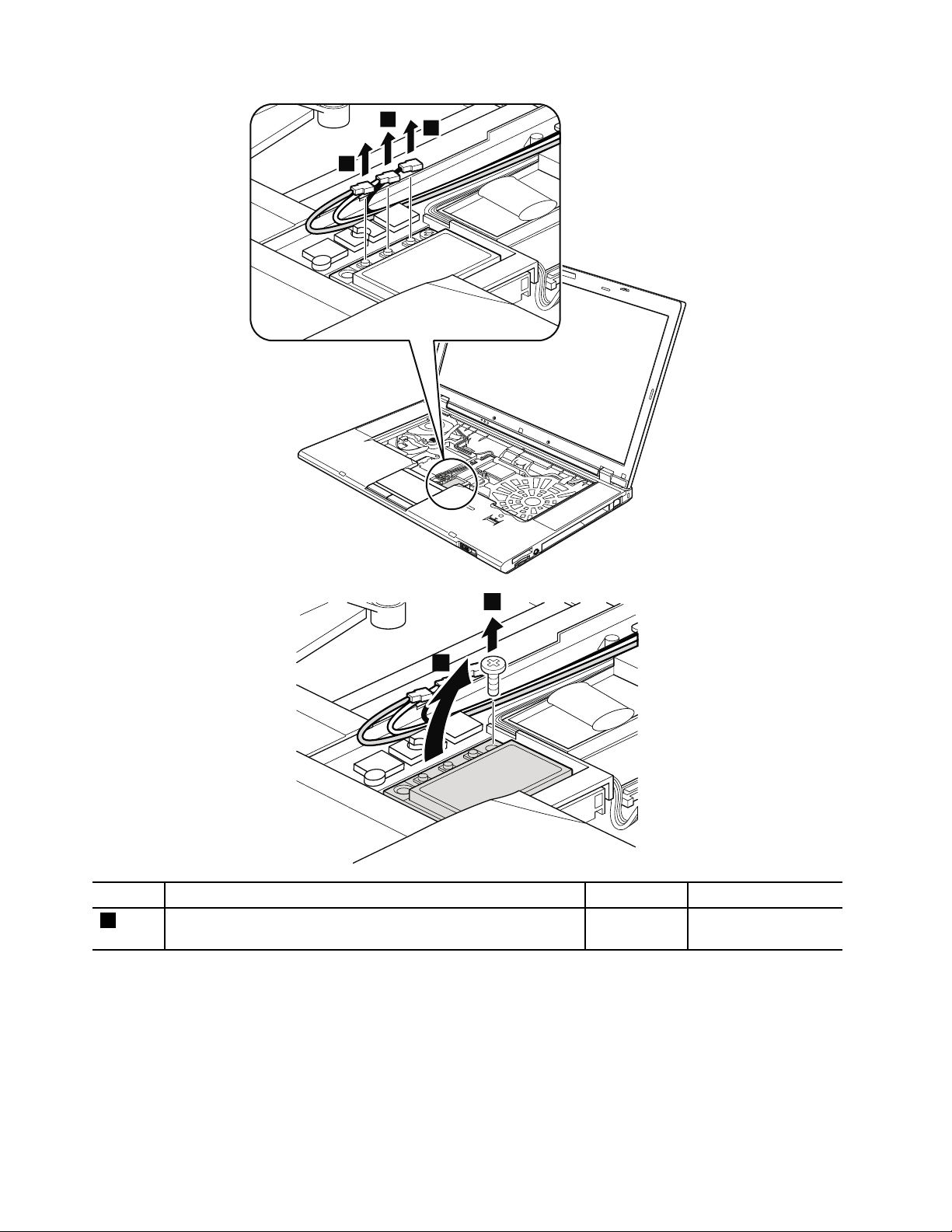
1
1
1
3
2
StepScrew(quantity)Color
2
M2×3mm,wafer-head,nylon-coated(1)Silver
78HardwareMaintenanceManual
Torque
0.181Nm
(1.85kgf-cm)
Page 85
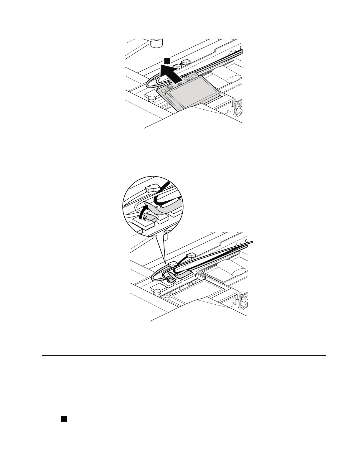
4
Wheninstalling:
•InmodelswithwirelessLANcardthathastwoantennaconnectors,plugthegraycableintothejack
labeledMAINorM,andtheblackcableintothejacklabeledAUXorAonthecard.Ifthecomputeryou
areservicinghasthreecables,putthewhitecableinthecableprotectiontubeasshowninthisgure.
•InmodelswithwirelessLANcardthathasthreeantennaconnectors,plugthegraycable(MAIN)into
thejacklabeledTR1,thewhitecable(3rd)intojacklabeledROorTR3,andtheblackcable(AUX)into
jacklabeledTR2onthecard.
1090PCIExpressMiniCardforwirelessWAN
Foraccess,removetheseFRUsinorder:
•“1010Batterypack”onpage66
•“1030DIMMslotcover”onpage68
•“1060Keyboard”onpage72
RemovalstepsofPCIExpressMiniCardforwirelessWAN
Instep1,unplugthejacksbyusingtheantennaRFconnectorremovaltool(P/N:08K7159)orpickthe
connectorswithyourngersandgentlyunplugthemindirectionofthearrow.
Chapter9.RemovingandreplacingaFRU79
Page 86
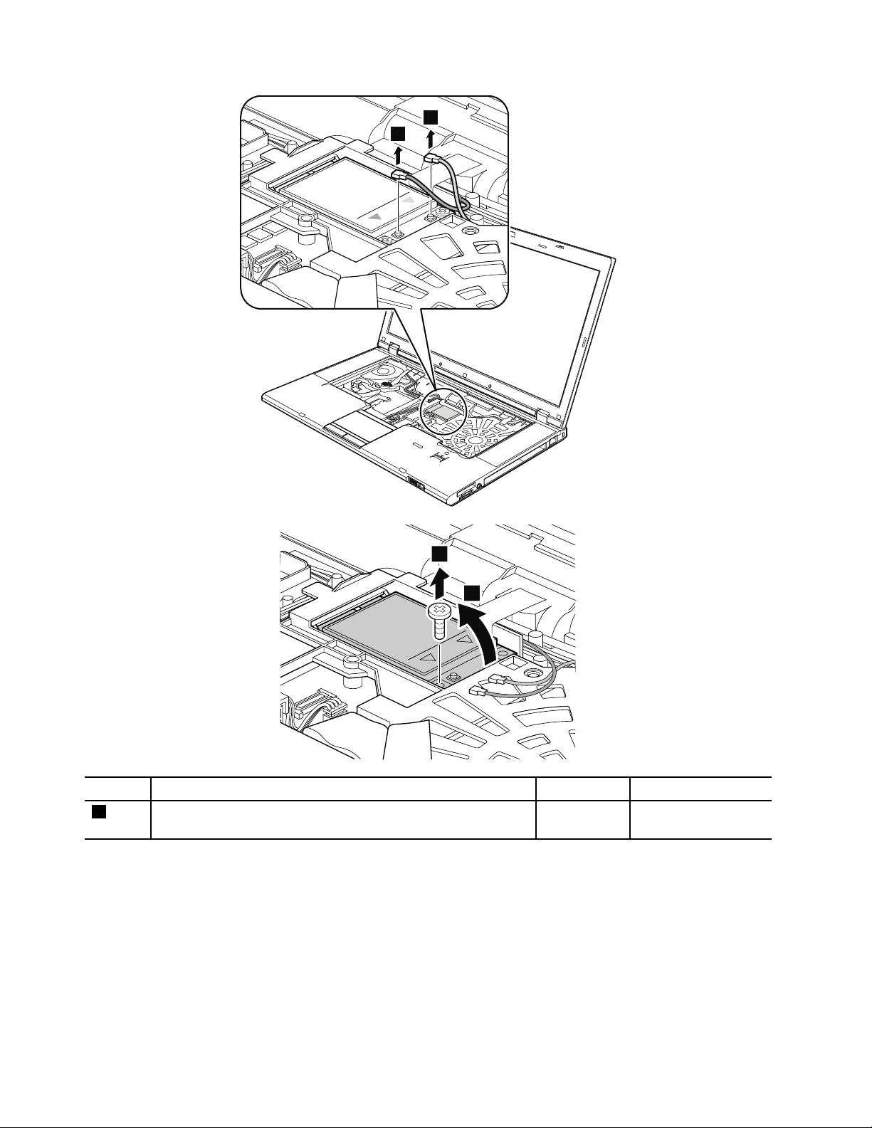
1
1
3
2
StepScrew(quantity)Color
2
M2×3mm,wafer-head,nylon-coated(1)Silver
80HardwareMaintenanceManual
Torque
0.181Nm
(1.85kgf-cm)
Page 87

4
Wheninstalling:PlugtheorangecableintothejacklabeledMAIN,andthebluecableintothejacklabeled
2
1
AUXonthecard.
1090mSAT Asolidstatedrive
Note:IfyourcomputerisequippedwithanmSA T Asolidstatedrive,itisinstalledintheWWANcardslot.
WWANcardandmSAT Asolidstatedriveareexclusivetoeachother.
Foraccess,removetheseFRUsinorder:
•“1010Batterypack”onpage66
•“1030DIMMslotcover”onpage68
•“1060Keyboard”onpage72
Attention:
•Donotdropthedriveorapplyanyphysicalshocktoit.Thedriveissensitivetophysicalshock.Improper
handlingcancausedamageandpermanentlossofdata.
•Beforeremovingthedrive,havetheusermakeabackupcopyofalltheinformationonitifpossible.
•Neverremovethedrivewhilethesystemisoperatingorisinsuspendmode.
RemovalstepsofmSATAsolidstatedrive
StepScrew(quantity)Color
2
M2×3mm,wafer-head,nylon-coated(1)Silver
Torque
0.181Nm
(1.85kgf-cm)
Chapter9.RemovingandreplacingaFRU81
Page 88

3
1100Keyboardbezelassembly
1
2
Foraccess,removetheseFRUsinorder:
•“1010Batterypack”onpage66
•“1030DIMMslotcover”onpage68
•“1060Keyboard”onpage72
Attention:Beforeremovingthekeyboardbezelassembly,makesurethatyouhaveremovedExpressCard
blankbezeloranycardintheslot.
RemovalstepsofExpressCardblankbezelorExpressCard
WhenyoupresstheExpressCardblankbezelorExpressCard1,itpopsout2.
Wheninstalling:Makesurethatthebezelorthecardiscorrectlyorientedasshowninthisgure.
82HardwareMaintenanceManual
Page 89
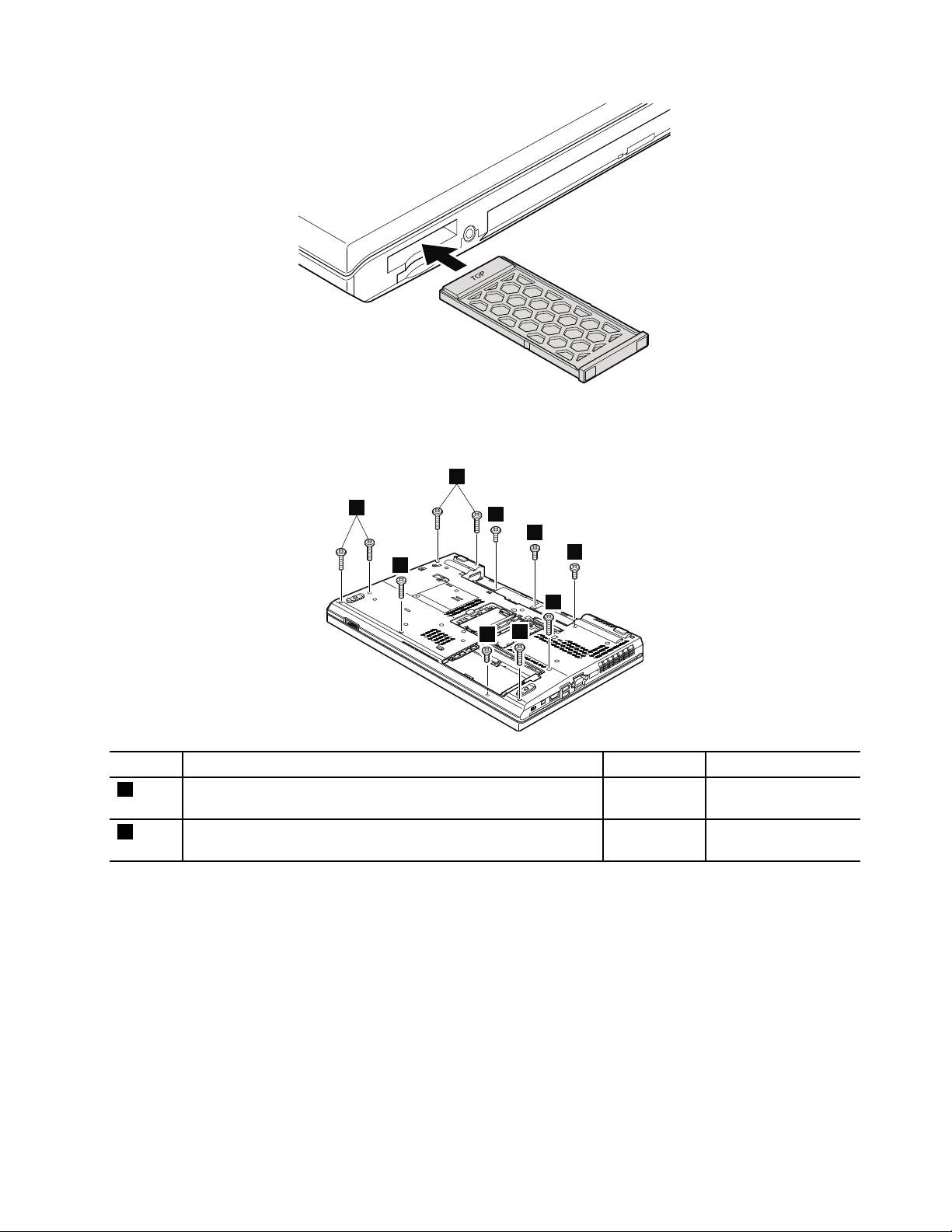
Removalstepsofkeyboardbezelassembly
1
2
2
2
1
1
1
2
2
Note:Thespeakerassemblyisattachedtothekeyboardbezel.
StepScrew(quantity)Color
1
M2×4mm,bind-head,nylon-coated(4)
Black0.181Nm
Torque
(1.85kgf-cm)
2
M2×14mm,bind-head,nylon-coated(7)
Black0.181Nm
(1.85kgf-cm)
Chapter9.RemovingandreplacingaFRU83
Page 90
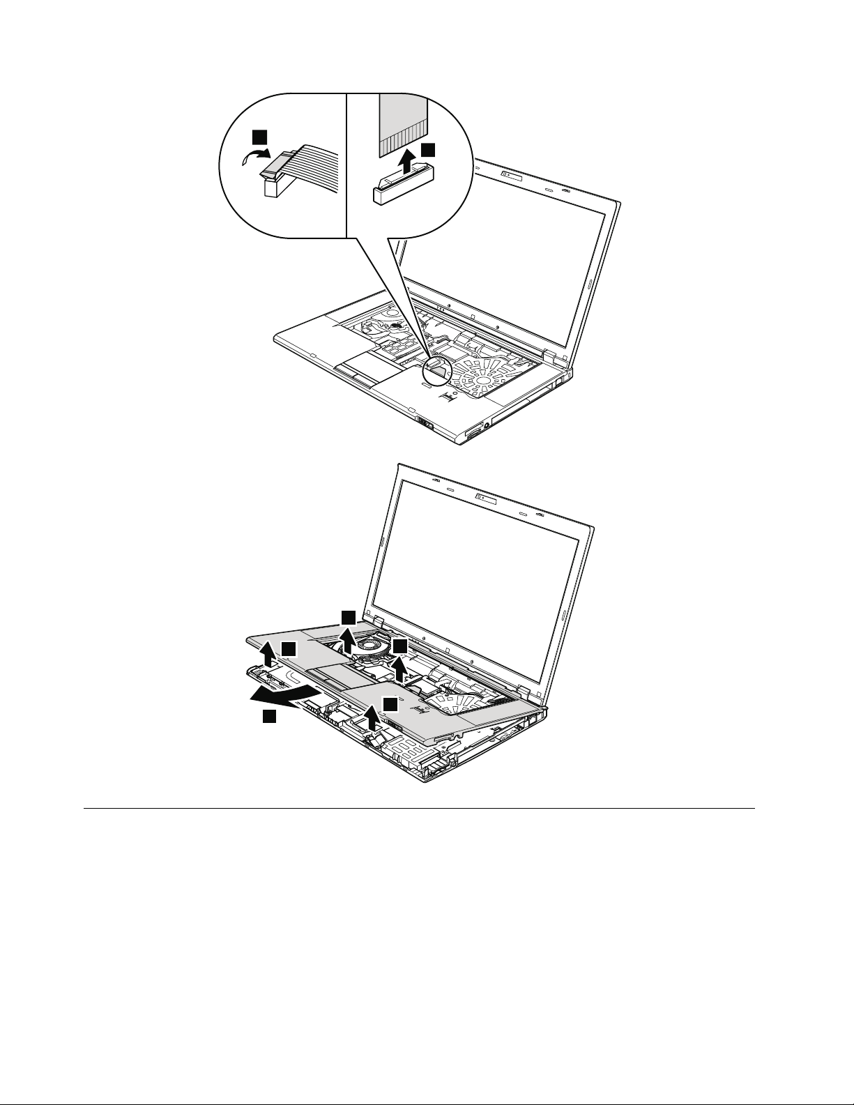
4
3
7
6
5
5
6
1110Bluetoothdaughtercard
Foraccess,removetheseFRUsinorder:
•“1010Batterypack”onpage66
•“1060Keyboard”onpage72
•“1100Keyboardbezelassembly”onpage82
84HardwareMaintenanceManual
Page 91

RemovalstepsofBluetoothdaughtercard
2
1
StepScrew(quantity)Color
1
M2×3mm,wafer-head,nylon-coated(1)Silver
Torque
0.181Nm
(1.85kgf-cm)
Wheninstalling:Makesurethattheconnectorisattachedrmly.
1120Backupbattery
Foraccess,removetheseFRUsinorder:
•“1010Batterypack”onpage66
•“1030DIMMslotcover”onpage68
•“1060Keyboard”onpage72
•“1100Keyboardbezelassembly”onpage82
Removalstepsofbackupbattery
DANGER
Useonlythebatteryspeciedinthepartslistforyourcomputer.Anyotherbatterycouldignite
orexplode.
Chapter9.RemovingandreplacingaFRU85
Page 92

1
2
Wheninstalling:Makesurethatthebatteryconnectorisattachedrmly.
1130SmartCardorSmartCarddummyspacer
Foraccess,removetheseFRUsinorder:
•“1010Batterypack”onpage66
•“1030DIMMslotcover”onpage68
•“1060Keyboard”onpage72
•“1100Keyboardbezelassembly”onpage82
86HardwareMaintenanceManual
Page 93

RemovalstepsofSmartCard
1
4
3
3
1
2
6
5
5
StepScrew(quantity)Color
3
M2×3mm,wafer-head,nylon-coated(3)Silver
Torque
0.181Nm
(1.85kgf-cm)
Chapter9.RemovingandreplacingaFRU87
Page 94

Removalstepsofdummycardandspacer
2
3
1
1
StepScrew(quantity)Color
1
M2×3mm,wafer-head,nylon-coated(3)Silver
1140Speakerassembly
Foraccess,removetheseFRUsinorder:
•“1010Batterypack”onpage66
•“1030DIMMslotcover”onpage68
•“1060Keyboard”onpage72
•“1100Keyboardbezelassembly”onpage82
Torque
0.181Nm
(1.85kgf-cm)
88HardwareMaintenanceManual
Page 95

Removalstepsofspeakerassembly
1
1
1
1
3
2
2
4
4
4
4
4
5
5
5
5
5
StepScrew(quantity)Color
1
M2×3mm,wafer-head,nylon-coated(4)Silver
Torque
0.181Nm
(1.85kgf-cm)
Wheninstalling:Makesurethatthespeakerconnectorisattachedrmly.Thenroutethecablesand
securethemproperlyasshowninthegureabove.
1150Thermalmodule
Foraccess,removetheseFRUsinorder:
Chapter9.RemovingandreplacingaFRU89
Page 96
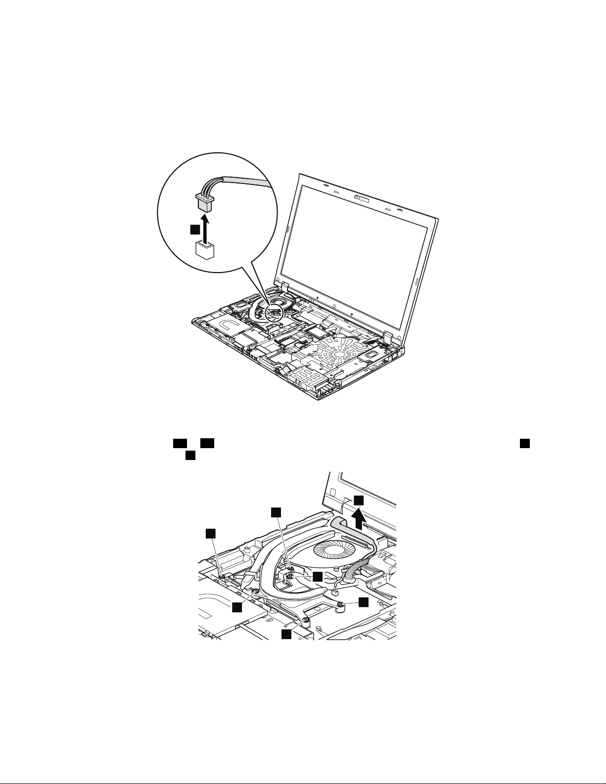
•“1010Batterypack”onpage66
1
2
3b
3a
3c
3d
4
4
•“1030DIMMslotcover”onpage68
•“1060Keyboard”onpage72
•“1100Keyboardbezelassembly”onpage82
•“1140Speakerassembly”onpage88
Removalstepsofthermalmodule
Wheninstalling:Makesurethattheconnectorsareattachedrmly.
Note:Loosenthescrews3ato3dinorder,butdonotremovethem.Somemodelsdonothavescrews4.
Forthosemodels,skipstep4.
90HardwareMaintenanceManual
Page 97
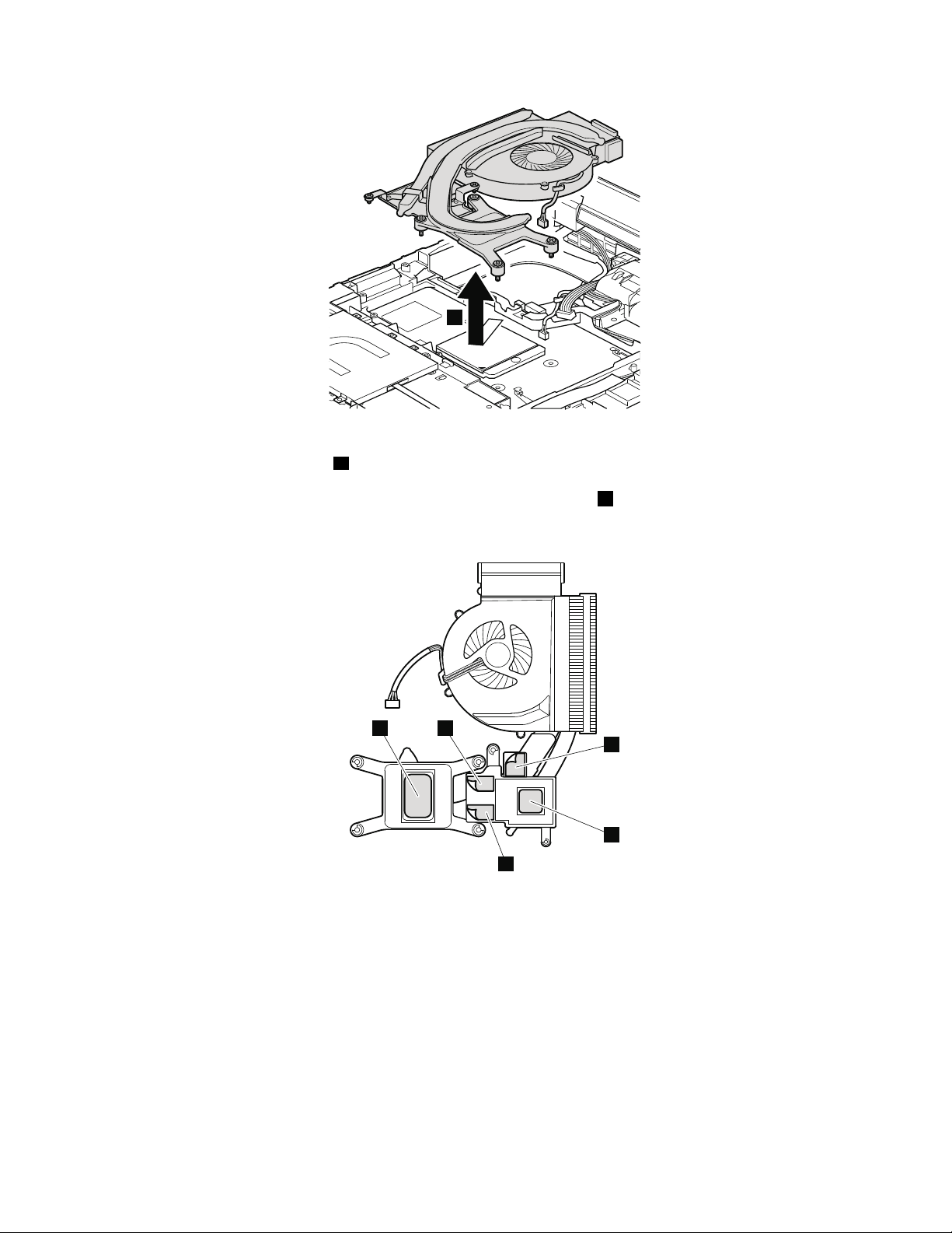
6
Wheninstalling:Beforeyouattachthefanassemblytothecomputer,applythermalgrease,atanamountof
a
a
b
b
b
0.2grams,onthepartsmarked
aasinthefollowinggures.Eithertoomuchortoolessapplicationof
greasecancauseathermalproblemduetoimperfectcontactwithacomponent.ForthenewCPUthermal
device/fan,youneedtopeelthethinlmofffromtherubbersmarkedb.
ForSwitchableGraphicsmodels:
ForIntegratedGraphicsmodels:
Chapter9.RemovingandreplacingaFRU91
Page 98
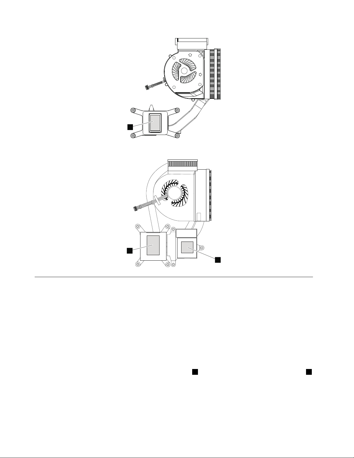
a
ForWorkstationmodels:
a
a
1160CPU
Foraccess,removetheseFRUsinorder:
•“1010Batterypack”onpage66
•“1030DIMMslotcover”onpage68
•“1060Keyboard”onpage72
•“1100Keyboardbezelassembly”onpage82
•“1140Speakerassembly”onpage88
•“1150Thermalmodule”onpage89
Attention:CPUisextremelysensitive.WhenyouservicetheCPU,avoidanykindofroughhandling.
RemovalstepsofCPU
Rotatetheheadofthescrewinthedirectionshownbyarrow1toreleasethelock;thenremovetheCPU2.
92HardwareMaintenanceManual
Page 99
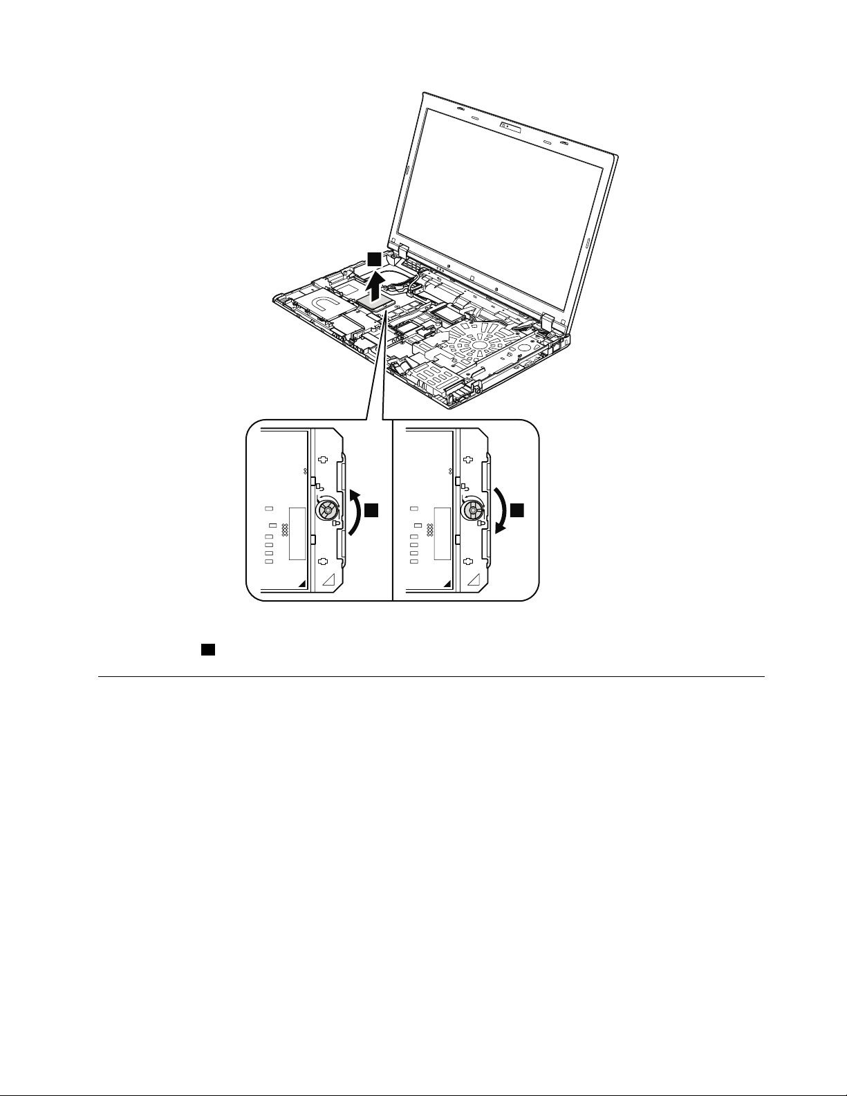
2
1 a
Wheninstalling:PlacetheCPUontheCPUsocket,andthenrotatetheheadofthescrewinthedirection
shownbyarrowatosecuretheCPU.
1170LCDunit
Foraccess,removetheseFRUsinorder:
•“1010Batterypack”onpage66
•“1030DIMMslotcover”onpage68
•“1050Harddiskdriveslotcover,harddiskdrive(HDD)andHDDrubberrailsorsolidstatedrive(SSD)
andstorageconverter”onpage71
•“1060Keyboard”onpage72
•“1080PCIExpressMiniCardforwirelessLAN”onpage77
•“1090PCIExpressMiniCardforwirelessWAN”onpage79or“1090mSA T Asolidstatedrive”onpage81
•“1100Keyboardbezelassembly”onpage82
Chapter9.RemovingandreplacingaFRU93
Page 100
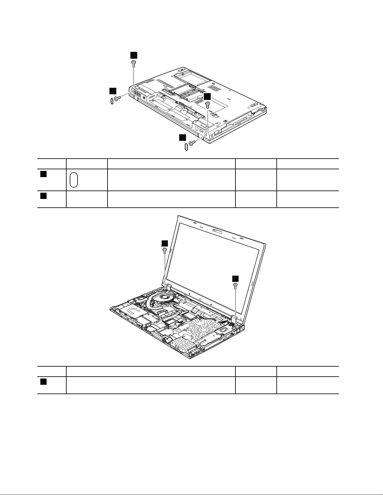
RemovalstepsofLCDunit
2
2
1
1
3
3
StepScrewcapScrew(quantity)Color
1
2—
M2.5×6mm,wafer-head,nylon-coated(2)
M2.5×6mm,wafer-head,nylon-coated(2)
Torque
Black0.392Nm
(4.0kgf-cm)
Black0.392Nm
(4.0kgf-cm)
StepScrew(quantity)Color
3
M2.5×6mm,wafer-head,nylon-coated(2)
Black0.392Nm
Torque
(4.0kgf-cm)
94HardwareMaintenanceManual
 Loading...