

Page 1

ThinkServer
InstallationandUserGuide
MachineTypes:1043,1044,4010,and4011
Page 2

Note
Beforeusingthisinformationandtheproductitsupports,besuretoreadandunderstandthefollowing:
•TheImportantNoticesthatcomeswithyourproduct
•TheSafetyInformationandtheWarrantyandSupportInformationonthedocumentationDVDthatcomes
withyourproduct
•AppendixC“Notices”onpage103
FourthEdition(June2011)
©CopyrightLenovo2010,2011.
LIMITEDANDRESTRICTEDRIGHTSNOTICE:IfdataorsoftwareisdeliveredpursuantaGeneralServicesAdministration
“GSA”contract,use,reproduction,ordisclosureissubjecttorestrictionssetforthinContractNo.GS-35F-05925.
Page 3

Contents
Safetyinformation..........iii
Chapter1.Generalinformation.....1
Introduction.................1
Noticesandstatementsinthedocument.....1
Relateddocumentation............2
Chapter2.Serversetuproadmap...3
Chapter3.Featuresand
technologies..............5
Whatisincludedwithyourserver........5
Features..................5
Specications................5
Softwareprograms..............7
EasyStartup...............7
EasyManage...............7
Reliability,availability,andserviceability......7
Chapter4.Locatingparts,controls,
LEDs,andconnectors.........9
Frontview.................9
Rearview..................9
Frontcontrolpanel.............10
Locatingservercomponents.........13
Locatingpartsonthesystemboard......13
Locatingconnectorsonthebackplane.....16
Chapter5.Installing,removing,or
replacinghardware..........17
Guidelines................17
Basicguidelines............17
Systemreliabilityguidelines........18
Handlingstatic-sensitivedevices.....18
Workinginsidetheserverwiththepoweron.19
Removingtheservercover..........19
Installing,removing,orreplacingoptionalhardware
devices.................20
Installingorremovingamemorymodule...20
Removingorinstallinginternaldrives....23
Installingorremovingtherisercard.....32
InstallingorremovingaPCIcard......35
RemovingorinstallingtheEthernetcard...37
Installing,removing,orreplacinghardware
devices.................38
Removingorinstallingthesystemboard
battery................38
RemovingorinstallingtheRAIDcontroller..40
Removingorinstallingtheheatsink
assembly...............52
Removingorinstallingthepowersupply...55
Removingorinstallingthemicroprocessor..60
Completingthepartsreplacement.......64
Installingtheservercover........64
Connectingthecables..........64
Turningontheserver..........65
Updatingtheserverconguration.....65
Turningofftheserver..........65
Connectingexternaldevices.......66
Chapter6.Conguringtheserver..67
UsingtheSetupUtilityprogram........67
StartingtheSetupUtilityprogram.....68
IntroductionoftheBIOSitems.......68
Usingpasswords............75
RAIDcontrollers..............76
UsingtheThinkServerEasyStartupprogram...76
BeforeyouusetheEasyStartupDVD....77
Setupandconguration.........77
ConguringRAID............78
Typicaloperatingsysteminstallation....78
ConguringtheonboardSATAsoftwareRAID..79
RAIDinformation............79
StartingtheIntelMatrixStorageManager
program...............79
CreatingtheRAIDvolume........79
DeletingtheRAIDvolume........80
RebuildingtheRAIDvolume.......80
ConguringtheGigabitEthernetcontroller....80
Updatingthermware............80
UsingtheEasyUpdateFirmwareUpdater
program...............80
InstallingtheThinkServerEasyManageprogram.81
Chapter7.Troubleshooting......83
Troubleshootingtables...........83
DVDdriveproblems...........83
Generalproblems............84
Harddiskdriveproblems.........84
Intermittentproblems..........84
Keyboard,mouse,orpointing-device
problems...............85
Memoryproblems...........85
Microprocessorproblems........86
Monitorproblems............87
©CopyrightLenovo2010,2011
i
Page 4

Optional-deviceproblems........88
Powerproblems............89
Serialportproblems...........90
Softwareproblems...........91
UniversalSerialBus(USB)portproblems..92
Solvingpowerproblems...........92
SolvingEthernetcontrollerproblems......92
Solvingundeterminedproblems........93
Eventlogs................94
Viewingeventlogswithoutrestartingthe
server................94
Systemeventlog..............95
DiagnosticLEDsonthefrontcontrolpanel...95
Onboarddebugdigitron...........95
AppendixA.RAIDbatterycard
assembly...............97
Specications...............97
Batterylifeanddataretentiontime.....97
AppendixB.Gettinghelpand
technicalassistance.........99
Beforeyoucall...............99
Usingthedocumentation..........99
GettinghelpandinformationfromtheWorldWide
Web...................99
LenovoSupportWebsite..........100
Callingforservice.............100
Usingotherservices............101
Purchasingadditionalservices........101
LenovoproductserviceinformationforTaiwan..101
AppendixC.Notices........103
Trademarks................104
Importantnotes..............104
Productrecyclinganddisposal........104
Particulatecontamination..........105
Turkishstatementofcompliance.......106
Batteryreturnprogram...........106
GermanOrdinanceforWorkglossstatement...107
Electronicemissionnotices..........107
FederalCommunicationsCommission(FCC)
Statement...............107
Index.................111
iiThinkServerInstallationandUserGuide
Page 5
Safetyinformation
Beforeinstallingthisproduct,readtheSafetyInformation.
©CopyrightLenovo2010,2011
iii
Page 6
Important:Eachcautionanddangerstatementinthisdocumentislabeledwithanumber.Thisnumber
isusedtocrossreferenceanEnglish-languagecautionordangerstatementwithtranslatedversionsof
thecautionordangerstatementintheSafetyInformationmanual.Forexample,ifacautionstatementis
labeled“Statement1,”translationsforthiscautionstatementareintheSafetyInformationmanualunder
“Statement1.”
Besuretoreadandunderstandallcautionanddangerstatementsinthisdocumentbeforeyouperform
theprocedures.Readandunderstandanyadditionalsafetyinformationthatcomeswiththeserveroran
optionaldevicebeforeyouinstall,remove,orreplacethedevice.
Statement1
DANGER
Electricalcurrentfrompower,telephone,andcommunicationcablesishazardous.
Toavoidashockhazard:
•Donotconnectordisconnectanycablesorperforminstallation,maintenance,orrecongurationofthis
productduringanelectricalstorm.
•Connectallpowercordstoaproperlywiredandgroundedelectricaloutlet.
•Connecttoproperlywiredoutletsanyequipmentthatwillbeattachedtothisproduct.
•Whenpossible,useonehandonlytoconnectordisconnectsignalcables.
•Neverturnonanyequipmentwhenthereisevidenceofre,water,orstructuraldamage.
•Disconnecttheattachedpowercords,telecommunicationssystems,networks,andmodemsbeforeyou
openthedevicecovers,unlessinstructedotherwiseintheinstallationandcongurationprocedures.
•Connectanddisconnectcablesasdescribedinthefollowingtablewheninstalling,moving,oropening
coversonthisproductorattacheddevices.
ToConnect:ToDisconnect:
1.TurneverythingOFF.
2.First,attachallcablestodevices.
3.Attachsignalcablestoconnectors.
4.Attachpowercordstooutlet.
5.TurndeviceON.
ivThinkServerInstallationandUserGuide
1.TurneverythingOFF.
2.First,removepowercordsfromoutlet.
3.Removesignalcablesfromconnectors.
4.Removeallcablesfromdevices.
Page 7
Statement2
CAUTION:
Whenreplacingthelithiumbattery,useonlythebatteryrecommendedbythemanufacturer.Ifyour
systemhasamodulecontainingalithiumbattery,replaceitonlywiththesamemoduletypemadeby
thesamemanufacturer.Thebatterycontainslithiumandcanexplodeifnotproperlyused,handled,or
disposedof.Donot:
•Throworimmerseintowater
•Heattomorethan100°C(212°F)
•Repairordisassemble
Disposeofthebatteryasrequiredbylocalordinancesorregulations.
Statement3
CAUTION:
Whenlaserproducts(suchasCD-ROMs,DVDdrives,beropticdevices,ortransmitters)are
installed,notethefollowing:
•Donotremovethecovers.Removingthecoversofthelaserproductcouldresultinexposureto
hazardouslaserradiation.Therearenoserviceablepartsinsidethedevice.
•Useofcontrolsoradjustmentsorperformanceofproceduresotherthanthosespeciedherein
mightresultinhazardousradiationexposure.
DANGER
SomelaserproductscontainanembeddedClass3AorClass3Blaserdiode.Notethefollowing.
Laserradiationwhenopen.Donotstareintothebeam,donotviewdirectlywithoptical
instruments,andavoiddirectexposuretothebeam.
Statement4
≥18kg(39.7lb)≥32kg(70.5lb)≥55kg(121.2lb)
<32kg(70.5lb)<55kg(121.2lb)<100kg(220.5lb)
CAUTION:
Usesafepracticeswhenlifting.
©CopyrightLenovo2010,2011
v
Page 8
Statement5
CAUTION:
Thepowercontrolbuttononthedeviceandthepowerswitchonthepowersupplydonotturnoff
theelectricalcurrentsuppliedtothedevice.Thedevicealsomighthavemorethanonepower
cord.T oremoveallelectricalcurrentfromthedevice,ensurethatallpowercordsaredisconnected
fromthepowersource.
Statement8
CAUTION:
Neverremovethecoveronapowersupplyoranypartthathasthefollowinglabelattached.
Hazardousvoltage,current,andenergylevelsarepresentinsideanycomponentthathasthislabel
attached.Therearenoserviceablepartsinsidethesecomponents.Ifyoususpectaproblemwith
oneoftheseparts,contactaservicetechnician.
Statement11
CAUTION:
Thefollowinglabelindicatessharpedges,corners,orjointsnearby.
Statement12
CAUTION:
Thefollowinglabelindicatesahotsurfacenearby.
viThinkServerInstallationandUserGuide
Page 9
Statement13
DANGER
Overloadingabranchcircuitispotentiallyarehazardandashockhazardundercertain
conditions.T oavoidthesehazards,ensurethatyoursystemelectricalrequirementsdonotexceed
branchcircuitprotectionrequirements.Refertotheinformationthatisprovidedwithyourdevice
forelectricalspecications.
Statement15
CAUTION:
Makesurethattherackissecuredproperlytoavoidtippingwhentheserverunitisextended.
Statement17
CAUTION:
Thefollowinglabelindicatesmovingpartsnearby.
Statement26
CAUTION:
Donotplaceanyobjectontopofrack-mounteddevices.
©CopyrightLenovo2010,2011
vii
Page 10

viiiThinkServerInstallationandUserGuide
Page 11

Chapter1.Generalinformation
Thischapterprovidessomegeneralinformationaboutyourserver.
Thischaptercontainsthefollowingtopics:
•“Introduction”onpage1
•“Noticesandstatementsinthedocument”onpage1
•“Relateddocumentation”onpage2
Introduction
ThisInstallationandUserGuideisforyourLenovo®ThinkServer®RD230server(machinetypes1043,1044,
4010,and4011).Thisdocumentcontainsthefollowinginformation:
•Settingupandcablingtheserver
•Startingandconguringtheserver
•Installingoptionsandreplacingcustomerreplaceableunits(CRUs)
•Solvingproblems
TheservercomeswiththeThinkServerEasyStartupDVDtohelpyoucongurethehardware,installdevice
drivers,andinstalltheoperatingsystem.
Theservercomeswithalimitedwarranty.Forinformationaboutthetermsofthewarrantyandgetting
serviceandassistance,seetheWarrantyandSupportInformationonthedocumentationDVDthatcomes
withyourserver.
Toobtainthemostup-to-dateinformationabouttheserverandotherLenovoproducts,goto:
http://www.lenovo.com/thinkserver
Recordinformationabouttheserverinthefollowingtable.Y ouwillneedthisinformationwhenyouregister
theserverwithLenovo.
Productname
Machinetype1043,1044,4010,or4011
Modelnumber
Serialnumber
Themodelnumberandserialnumberareonthelabelsonthebottomoftheserverandonthefront,visible
throughthebezel.
ThinkServerRD230
_____________________________________________
_____________________________________________
Noticesandstatementsinthedocument
ThecautionanddangerstatementsthatappearinthisdocumentarealsointhemultilingualSafety
Information.Eachcautionanddangerstatementinthisdocumentislabeledwithanumber.Thisnumberis
usedtocrossreferenceanEnglish-languagecautionordangerstatementwithtranslatedversionsofthe
cautionordangerstatementintheSafetyInformation.See“Relateddocumentation”onpage2
informationabouthowtogetthevariousdocumentationforyourserver.
fordetailed
©CopyrightLenovo2010,2011
1
Page 12
Thefollowingnoticesandstatementsareusedinthisdocument:
•Note:Thesenoticesprovideimportanttips,guidance,oradvice.
•Important:Thesenoticesprovideinformationoradvicethatmighthelpyouavoidproblemsor
inconvenientsituations.
•Attention:Thesenoticesindicatepotentialdamagetoprograms,devices,ordata.Anattentionnoticeis
placedjustbeforetheinstructionorsituationinwhichdamagecouldoccur.
•Caution:Thesestatementsindicatesituationsthatcanbepotentiallyhazardoustoyou.Acaution
statementisplacedjustbeforethedescriptionofapotentiallyhazardousproceduresteporsituation.
•Danger:Thesestatementsindicatesituationsthatcanbepotentiallylethalorextremelyhazardous
toyou.Adangerstatementisplacedjustbeforethedescriptionofapotentiallylethalorextremely
hazardousproceduresteporsituation.
Relateddocumentation
TheLenovodocumentationDVD,whichcomeswithyourserver,containsdocumentationfortheserverin
PortableDocumentFormat(PDF).ToviewthedocumentationonthedocumentationDVD,youneedtohave
theAdobeReader5.0programorlaterinstalled,orthexpdf,whichcomeswithLinux®operatingsystems.
Thefollowingtableprovidesinformationaboutthegeneraldescriptionsofthevariousdocumentation
providedwithyourserverandhowtoobtainallthedocumentation.
Table1.Relateddocumentationfortheserver
DocumentationDescriptionLocation
HardwareMaintenance
Manual
ImportantNotices
RackInstallation
Instructions
ReadMeFirstThisdocumentdirectsyoutothe
SafetyInformation
WarrantyandSupport
Information
Note:Y oucanobtainallthedocumentationinPDFforyourserverfromtheLenovoSupportWebsiteat
http://www.lenovo.com/support.
Thisdocumentprovidesdiagnostic
information,partslisting,replacement
proceduresforallCRUs,andreplacement
proceduresforothereldreplaceableunits
(FRUs)replacedbytrainedservicepersonnel.
Thisdocumentincludessafetyandlegal
noticesthatyouareexpectedtoreadbefore
usingtheserver.
Thisdocumentprovidesinstructionsonhow
toinstallyourserverinarack.
documentationDVDforcompletewarranty
andsupportinformation.
Thisdocumentincludestranslationsofall
safetystatementsusedintheThinkServer
documentation.
Thisdocumentincludesthewarranty
statementandinformationabouthowto
contactLenovoSupport.
ThisdocumentisinEnglishandposted
ontheLenovoSupportWebsiteat
http://www.lenovo.com/support.
Thisdocumentisprintedoutand
providedinserverpackaging.
TheEnglishversionofthisdocumentis
printedoutandprovidedintheserver
packaging.Additionallanguagesare
providedonthedocumentationDVD
andontheLenovoSupportWebsite:
http://www.lenovo.com/support
Thisdocumentisprintedoutand
providedinserverpackaging.
AvailableonthedocumentationDVD
AvailableonthedocumentationDVD
2ThinkServerInstallationandUserGuide
Page 13

Chapter2.Serversetuproadmap
Thischapterprovidesageneralroadmaptoguideyouthroughsettingupyourserver.
Theserversetupprocedurevariesdependingonthecongurationoftheserverwhenitwasdelivered.In
somecases,theserverisfullyconguredandyoujustneedtoconnecttheservertothenetworkandan
electricaloutlet,andthenyoucanturnontheserver.Inothercases,theserverneedstohavehardware
featuresinstalled,requireshardwareandrmwareconguration,andrequirestheoperatingsystemto
beinstalled.
Table2.Serversetuproadmap
TaskWheretondtheinformation
Unpack
Installhardware
InstalltheserverintherackTheRackInstallationInstructionsmanualisprintedandalsoincludedonthe
ConnecttheEthernetcable
andpowercord
Turnontheservertoverify
operation
ReviewtheBIOSsettings
andcustomizeasneeded
CongureRAID(onboard
SATARAIDortheinstalled
SASRAIDadapter)
Checkforrmwareupdates
Installoperatingsystemand
basicdrivers
Installanyadditionaldrivers
neededforaddedfeatures
CongureEthernetsettings
intheoperatingsystem
Installremotemanagement
applications
Installapplications
Chapter3“Featuresandtechnologies”onpage5
Chapter5“Installing,removing,orreplacinghardware”onpage17
documentationDVD.
“Rearview”onpage9
“Turningontheserver”onpage65
“StartingtheSetupUtilityprogram”onpage68
“RAIDcontrollers”onpage76
“UsingtheEasyUpdateFirmwareUpdaterprogram”onpage80
“UsingtheThinkServerEasyStartupprogram”onpage76
Refertotheinstructionsthatcamewiththehardwareoption.
Seetheoperatingsystemhelp.Thisstepisnotrequirediftheoperatingsystemwas
installedusingtheThinkServerEasyStartupprogram.
“InstallingtheThinkServerEasyManageprogram”onpage81
Refertothedocumentationthatcomeswiththeapplicationsthatyouwanttoinstall.
©CopyrightLenovo2010,2011
3
Page 14

4ThinkServerInstallationandUserGuide
Page 15

Chapter3.Featuresandtechnologies
Whatisincludedwithyourserver
TheRD230serverpackageincludestheserver,apowercord,documentation,thedocumentationDVD,and
softwaremedia.
Features
TheRD230serveroffersthefollowingfeaturesandtechnologies:
•Microprocessor(s):TheserversupportsuptotwoIntel®Xeon®dual-core,quad-core,orhex-core
microprocessors.
•BIOS:Theserverrmwaredenesastandardinterfacebetweentheoperatingsystem,platformrmware,
andexternaldevices.
•EasyStartupDVD:TheThinkServerEasyStartupprogramguidesyouthroughthecongurationofthe
hardware,theredundantarrayofindependentdisks(RAID)controller,andtheinstallationoftheoperating
systemanddevicedrivers.
•Integratednetworksupport:
controllersandeachsupportsconnectiontoa10Mbps,100Mbps,or1000Mbpsnetwork.Formore
information,see“ConguringtheGigabitEthernetcontroller”onpage80.
•Largedata-storagecapacityandhot-swapcapability:Somehot-swapservermodelssupportfour
3.5-inchhot-swapharddiskdrives.Withthehot-swapfeature,youcanadd,remove,orreplaceharddisk
driveswithoutturningofftheserver.
•Largesystem-memorycapacity:Theserversupportsupto64GBofsystemmemory.Thememory
modulesupportserrorcorrectingcode(ECC)foruptoeightindustry-standardsingle-rankordual-rank,
1333MHz,DDR3(third-generationdouble-data-rate)registeredsynchronousdynamicrandomaccess
memory(SDRAM)dualinlinememorymodules(DIMMs).
•High-performancegraphicscontroller:Theservercomeswithanonboardhigh-performancegraphics
controllerthatsupportshighresolutionsandincludesmanyperformance-enhancingfeaturesforthe
operating-systemenvironment.
•Redundantconnection:
toaredundantEthernetconnection.IfaproblemoccurswiththeprimaryEthernetconnection,all
Ethernettrafcthatisassociatedwiththeprimaryconnectionisautomaticallyswitchedtotheredundant
NIC.Iftheapplicabledevicedriversareinstalled,thisswitchingoccurswithoutdatalossandwithout
userintervention.
•IntelligentPlatformManagementInterface(IPMI)2.0:Thecommand-lineinterfaceprovidesdirect
accesstoservermanagementfunctionsthroughtheIPMI2.0protocol.Usethecommand-lineinterface
toissuecommandstocontroltheserverpower,viewsysteminformation,andidentifytheserver.Y oucan
alsosaveoneormorecommandsasatextleandruntheleasascript.
•RAIDsupport:TheserversupportstheonboardSATAsoftwareRAIDandanadd-onSASRAIDcard
(ThinkServer8708ELPSASRAIDAdapter,ThinkServer8708EM2RAIDAdapter,orThinkServerRAID
700Adapter),whicharerequiredforyoutousethehot-swapSATAorSASharddiskdrivesandto
createtheRAIDcongurations.
Theservercomeswithtwointegratedsingle-portGigabitEthernet
Thetwoonboardnetworkinterfacecontrollers(NIC)provideafailovercapability
Specications
Thefollowinginformationisasummaryofthefeaturesandspecicationsoftheserver.Dependingonthe
servermodel,somefeaturesmightnotbeavailable,orsomespecicationsmightnotapply.
©CopyrightLenovo2010,2011
5
Page 16
Table3.Featuresandspecications
Microprocessor(s):Supportsupto
twoIntelXeondual-core,quad-core,
orhex-coremicroprocessors.Forthe
specictypeandspeedinformation
aboutthemicroprocessor,use
theSetupUtilityprogram.See
“UsingtheSetupUtilityprogram”on
page67
microprocessorsforyourserver,goto
http://www.lenovo.com/thinkserver.
OntheThinkServersystemspage,
clickProducts➙Options➙
ThinkServerProcessors.
Memorymodules:
•Minimumsystemmemory:2GB
•Maximumsystemmemory:64GB
•T ypes:ECC,1333MHz,DDR3
•Slots:Eightdualinlinememory
•Supports2GB,4GB,and8GB
Integratedgraphicscard:
•8MBvideomemory
Size:
•Height:43.6mm(1.72inches)
•Width:436mm(17.17inches)
•Depth:568mm(22.36inches)
•
.Foralistofthesupported
(eightmemoryslots,eachwithone
8GBRDIMMinstalled)
registeredSDRAMDIMMsonly
module(DIMM)slots
RDIMMs
Maximumweight:17kg(37.48lb)
whenfullycongured
Opticaldrive:
•SlimDVD/RW
Harddiskdriveexpansionbays
(dependingonthemodel):
Uptofour3.5-inchSATAorSAShard
diskdrives
Expansionslots:
•ThreePCIExpressslotsonthe
systemboardandthePCIExpress
x16slotisforarisercard(thereis
onePCIExpressx16slotonthe
risercard)
Powersupply:
powersupply
Systemfans:Fivesystemfans
withautomaticenergy-savingnoise
reductiontechnology
Integratedfunctions:
•T wosingle-portGbEthernet
controllers
•SixUSB2.0connectors(twofront
andfourrear)
•T woRJ-45Ethernetconnectors
•Oneserialport
•OneVideoGraphicsArray(VGA)
monitorconnector
Single600-watt
Environment:
•Airtemperature:
–Serveron:10°Cto35°C(50°F
to95°F);altitude:0to914.4m
(3000ft)
–Serveron:10°Cto32°C(50°F
to89.6°F);altitude:914.4m(3
000ft)to2133.6m(7000ft)
–Serveroff:10°Cto43°C(50°F
to109.4°F);maximumaltitude:
2133.6m(7000ft)
–Shipping:-40°Cto60°C(-104°F
to140°F)
•Humidity:
–Serveron:8-90%,
non-condensing
–Serveroff:8-90%,
non-condensing
–Shippingandstorage:upto
93%,non-condensing
•Particulatecontamination:
Attention:Airborneparticulates
andreactivegasesactingalone
orincombinationwithother
environmentalfactorssuchas
humidityortemperaturemight
posearisktotheserver.
6ThinkServerInstallationandUserGuide
Page 17
Table3.Featuresandspecications(continued)
RAIDcontrollers:
•OnboardSATASoftwareRAID
•ThinkServer8708ELPSASRAID
Adapter
•ThinkServer8708EM2RAID
Adapter
•ThinkServerRAID700Adapter
Electricalinput
•Inputvoltage:
–Lowrange:
–Highrange:
Minimum:100Vac
Maximum:127Vac
Inputfrequencyrange:50to
60Hz
Minimum:200Vac
Maximum:240Vac
Inputfrequencyrange:50to
60Hz
Notes:
1.Powerconsumptionandheat
outputvarydependingonthe
numberandtypeofoptional
featuresinstalledandthe
power-managementoptional
featuresinuse.
2.Thesoundlevelsweremeasured
incontrolledacoustical
environmentsaccordingto
theproceduresspeciedbythe
AmericanNationalStandards
Institute(ANSI)S12.10and
ISO7779andarereportedin
accordancewithISO9296.
Actualsound-pressurelevelsina
givenlocationmightexceedthe
averagevaluesstatedbecause
ofroomreectionsandother
nearbynoisesources.The
noiseemissionlevelstated
isthedeclared(upperlimit)
sound-powerlevel,inbels,fora
randomsampleofsystem.
3.Thereisnokeyboardconnector
ormouseconnectoronthe
server.Y oucanconnectaUSB
keyboardandUSBmouseto
theserverbyusingtheUSB
connectors.
Softwareprograms
Lenovoprovidessoftwaretohelpgetyourserverupandrunning.
EasyStartup
TheThinkServerEasyStartupprogramsimpliestheprocessofconguringRAIDandinstallingsupported
Microsoft®Windows®andLinuxoperatingsystemsanddevicedriversonyourserver.TheEasyStartup
programisprovidedwithyourserverontheThinkServerEasyStartupDVD.TheDVDisself-starting
(bootable).TheuserguidefortheEasyStartupprogramisontheDVDandcanbeaccesseddirectlyfromthe
programinterface.Foradditionalinformation,see“UsingtheThinkServerEasyStartupprogram”onpage76
EasyManage
TheThinkServerEasyManageAgentenablesthisservertobemanagedbythecentralizedconsoleofan
EasyManageCoreServeroverthenetwork.TheThinkServerEasyManageAgentissupportedon32-bitand
64-bitWindows,RedHat,andSUSEoperatingsystems.
Reliability,availability,andserviceability
Reliability,availability,andserviceability(hereafterreferredtoasRAS)arethreeimportantserverdesign
features.TheRASfeatureshelpyoutoensuretheintegrityofthedatastoredontheserver,theavailabilityof
theserverwhenyouneedit,andtheeasewithwhichyoucandiagnoseandcorrectproblems.
.
Chapter3.Featuresandtechnologies7
Page 18

TheserverhasthefollowingRASfeatures:
•AdvancedCongurationandPowerInterface(ACPI)
•AdvancedDesktopManagementInterface(DMI)
•Automaticmemorydownsizingonerrordetection
•Automaticrestartonnon-maskableinterrupt(NMI)
•Availabilityofmicrocodelevel
•Built-in,menu-drivensetup,systemconguration,andRAIDconguration
•Built-inmonitoringforfan,temperature,andvoltage
•Coolingfanswithspeed-sensingcapability
•ECCDDR3SDRAMwithSerialPresenceDetect(SPD)
•Errorcodesandmessagestohelpyouidentifyproblems
•Generatingerrorlogsforthepower-onself-test(POST)failures
•Hot-swapSASharddiskdrives
•IntegratedEthernetcontrollers
•IntelligentPlatformManagementInterface(IPMI)2.0
•Power-onself-test(POST)
•RedundantEthernetconnectionwithfailovercapability(requiresanoptionalEthernetcard)
•Standbyvoltageforsystem-managementfeaturesandmonitoring
•System-errorlight-emittingdiode(LED)onthefrontpanel
•Vitalproductdata(VPD),includingtheserialnumberinformationandreplacementpartnumbers,storedin
thenonvolatilememoryforeasierremotemaintenance
8ThinkServerInstallationandUserGuide
Page 19
Chapter4.Locatingparts,controls,LEDs,andconnectors
Thischapterprovidesinformationtohelpyoulocateyourserverparts,controls,light-emittingdiodes
(LEDs),andconnectors.
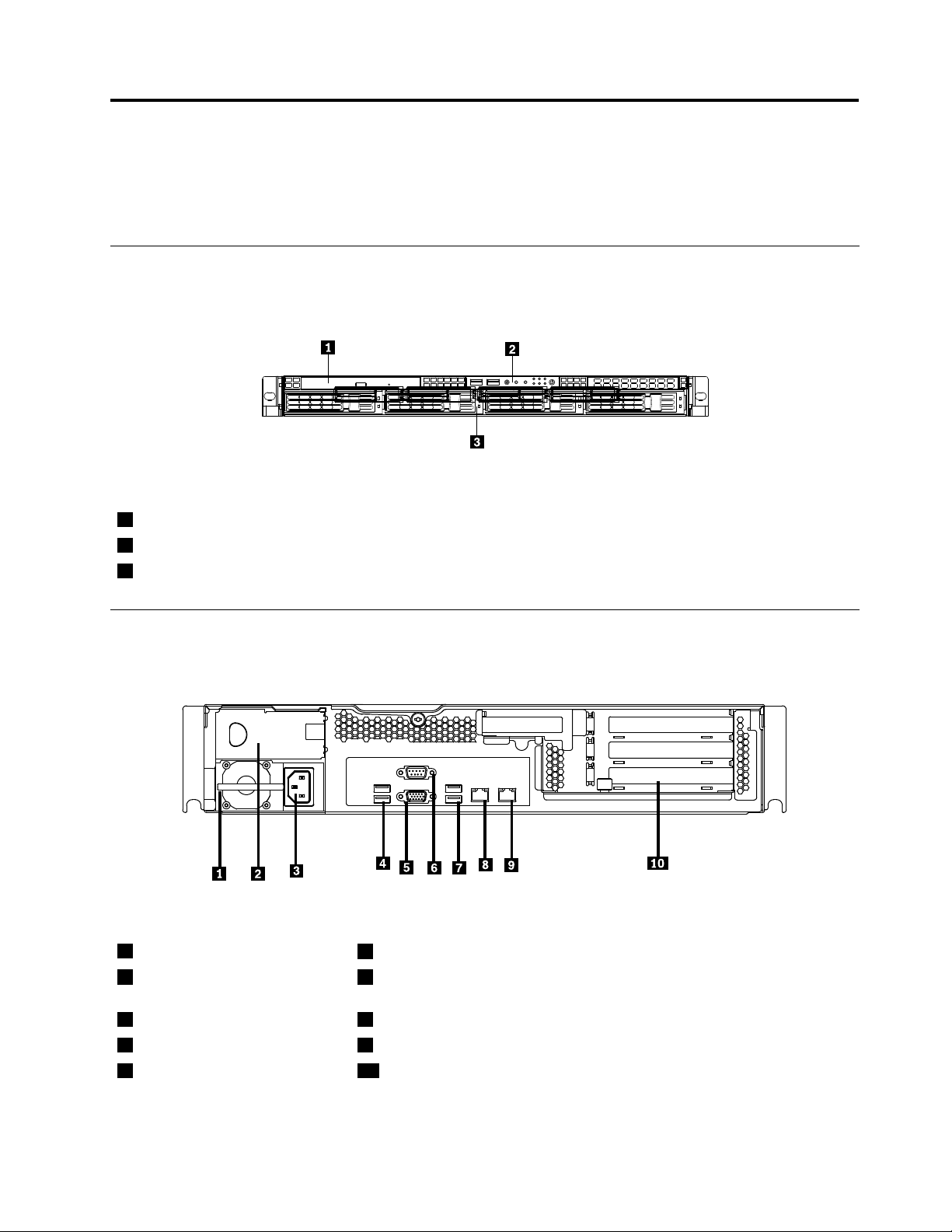
Frontview
Thefollowingillustrationshowsthedrivesandpartsonthefrontoftheserver.
Figure1.Frontviewoftheserver
1Slimopticaldrive
2Frontcontrolpanel(see“Frontcontrolpanel”onpage10)
3Mountingpointfor3.5-inchharddiskdrive
Rearview
Thefollowingillustrationshowsthelocationsoftheconnectorsandpartsontherearoftheserver.
Figure2.Rearviewoftheserver
1Powersupply1
2Powersupply2bay(blankand
coveredbyabaybezel)
3Powercordconnector8Ethernetconnector1
4USBconnectors(1and2)9Ethernetconnector2(sharewithMGMT)
5VGAmonitorconnector10PCIexpansionslot
6Serialport
7USBconnectors(3and4)
©CopyrightLenovo2010,2011
9
Page 20
ConnectorDescription
PowercordconnectorUsedtoconnectthepowercord.
Ethernetconnector
Serialport
UsedtoattachanEthernetcableforalocalareanetwork(LAN).
Usedtoattachadevicethatusesa9-pinserialport.
USBconnectorUsedtoattachadevicethatusesaUSBconnector,suchasaUSBkeyboard
oraUSBmouse.
VGAmonitorconnectorUsedtoattachaVGAmonitororotherdevicesthatuseaVGAmonitorconnector.
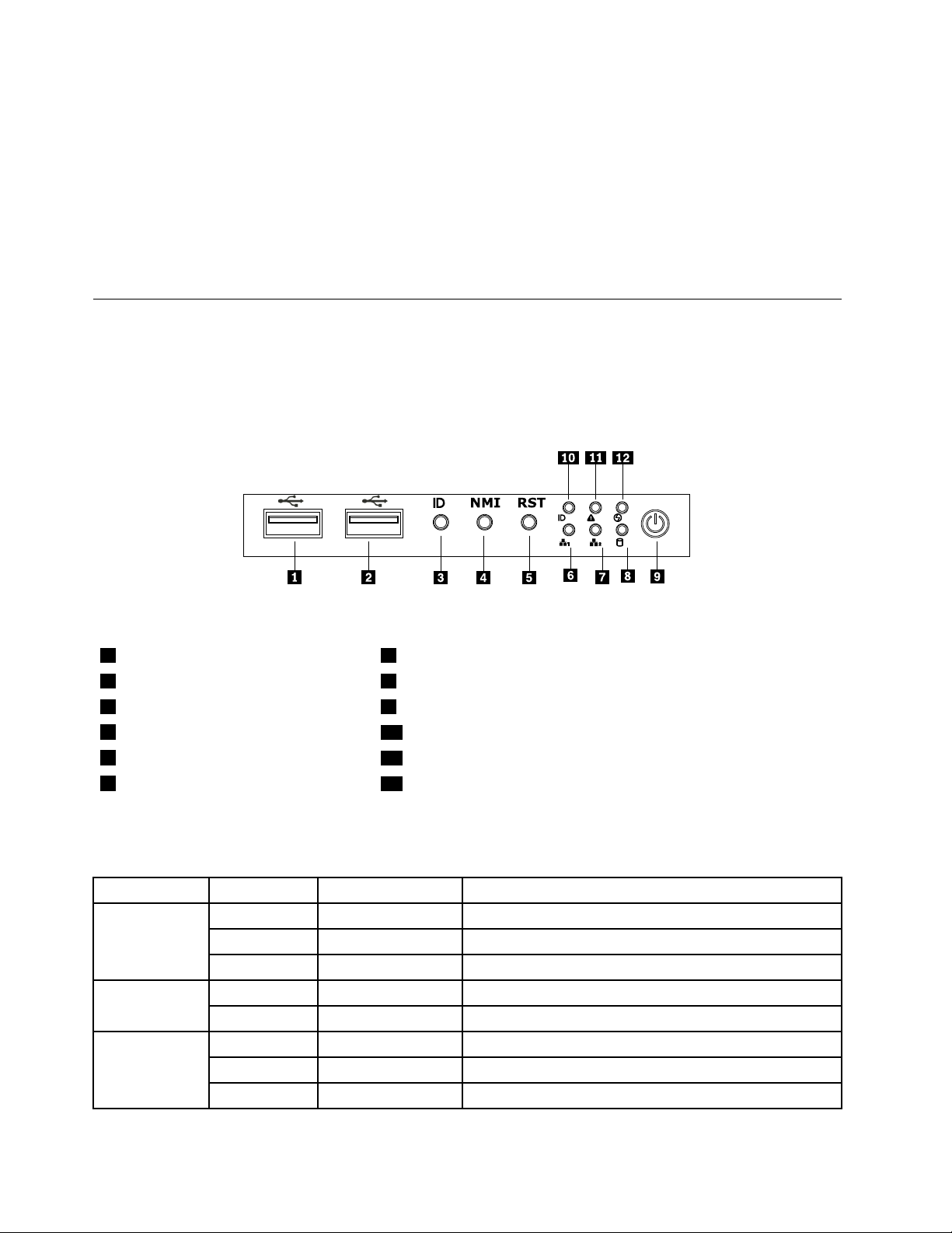
Frontcontrolpanel
Thissectionprovidesinformationaboutthefrontcontrolpaneloftheserver.
Thefollowingillustrationhelpsyouidentifytheconnectors,controls,andLEDsonthefrontcontrolpanelof
yourserver.
Figure3.Frontcontrolpanellocations
1USBconnector
2USBconnector
3IDbutton9PowerbuttonandLED
4NMIbutton
5Resetbutton
6Ethernet1statusLED
7Ethernet2statusLED
8HarddiskdrivestatusLED
10SystemIDLED
11SystemstatusLED
12LED(willnotbeusedinthisserver)
ThefollowingtabledescribesthemeaningoftheLEDsonthefrontcontrolpanel.
Table4.FrontcontrolpanelLEDs
LEDStateColorDescription
PowerLED
LED
Ethernet1
statusLED
OnGreen
Blinking
OffOff
OffOff
Blinking
OnGreen
Blinking
OffOff
GreenTheserverpowerisunderS1.
Green
Green
Theserverpowerison.
Theserverpowerisoff.
Theharddiskdriveisnotactive. Harddiskdrive
Theharddiskdriveisactive.
LANislinked.
LANisactive.
LANisnotlinked.
10ThinkServerInstallationandUserGuide
Page 21
Table4.FrontcontrolpanelLEDs(continued)
LEDStateColorDescription
Ethernet2
statusLED
LED
IDLED
OnGreen
Blinking
OffOff
On
OffOff
On
OffOffSystemisnotidentied.
Green
Red
Blue
LANislinked.
LANisactive.
LANisnotlinked.
Failure.Overtemperatureorovervoltage. Systemstatus
Nofailure.
Systemisidentied.
EachharddiskdrivehastwostatusLEDsonthefront.ThegreenLED1(bottom)indicatesactivityand
theamberLED2(top)indicatestheRAIDstatus.
Notes:IftheonboardSATAandonboardSATAsoftwareRAIDarecongured,notethefollowing:
•TheSGPIOconnectorofthe4–portSATAcableinthechassisshouldbeconnectedtotheJ45connector
onthesystemboard.See“Locatingpartsonthesystemboard”onpage13
.
•ThefunctionoftheamberLED2isonlyavailableafteryouentertheoperatingsystem.
Table5.HarddiskdriveLEDs
GreenLED1
Description
Harddiskdriveisnotpresent.
Harddiskdriveispresentbutisnotactive.
Harddiskdriveispresentandactive.Blinking
Serverisintheprocessoflocatingtheharddiskdrive.On
RAIDhasfailed.
Harddiskdriveisrebuilding.BlinkingBlinking
(bottom)AmberLED2(top)
OffOff
OnOff
Off
Blinking
OffOn
Note:Forsomemodels,theharddiskdrivestatusinformationmightbedifferentfromtheinformationlistedin
theabovetable.Fortheseservermodels,refertothefollowingtwotablesfortheharddiskdriveLEDstatus.
Table6.HarddiskdriveLEDsfortheonboardSA TAandonboardSATAsoftwareRAIDcongurations(somemodels)
GreenLED1
Description
Harddiskdriveisnotpresent.
Harddiskdriveispresentbutisnotactive.
Harddiskdriveispresentandactive.Blinking
Serverisintheprocessoflocatingtheharddiskdrive.OnOff
RAIDhasfailed.
Harddiskdriveisrebuilding.Blinking
Chapter4.Locatingparts,controls,LEDs,andconnectors11
(bottom)AmberLED2(top)
OffOff
OnOff
Off
OnOff
Off
Page 22
Table7.HarddiskdriveLEDsfortheadd-onSASRAIDadapterconguration(somemodels)
GreenLED1
Description
Harddiskdriveisnotpresent.
Harddiskdriveispresentbutisnotactive.
Harddiskdriveispresentandactive.Blinking
Serverisintheprocessoflocatingtheharddiskdrive.
RAIDhasfailed.
Harddiskdriveisrebuilding.BlinkingBlinking
(bottom)AmberLED2(top)
OffOff
OnOff
Off
BlinkingBlinking
OffOn
TheEthernet1andEthernet2connectorshavetwostatusLEDsthatindicatetheLANconnectionand
activityoftheconnection.
Table8.EthernetLEDs
LEDStateColorDescription
RJ-45linkage/activity(left)
RJ-45speed(right)
OnGreen10/100/1000Mblinked
Blinking
OffOff
On
OnGreen
OffOff
Green10/100/1000Mbactivity
NoLANconnection.
Amber1000Mblinkedandactive
100Mblinkedandactive
10MbmodeornoLANconnection.
12ThinkServerInstallationandUserGuide
Page 23
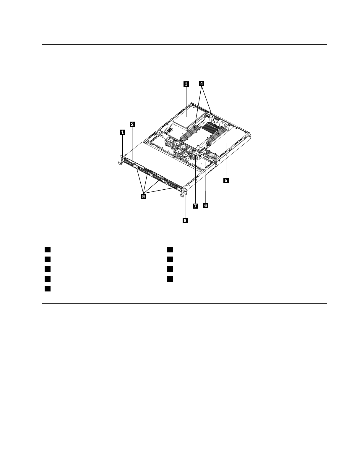
Locatingservercomponents
Thefollowingillustrationshowsthelocationsofthemajorcomponentsinyourserver.
Figure4.Servercomponentlocations
1Lefthandleofthechassis
2Slimopticaldrive7Systemfans
3PCIcard
4Memorymodules
5Powersupplyassembly
6Heatsinkassemblyandmicroprocessor(s)underneath
8Righthandleofthechassis
9Mountingpointsforthe3.5-inchharddiskdrives
Locatingpartsonthesystemboard
Thefollowingillustrationsshowthelocationsofthepartsonthesystemboard.
Chapter4.Locatingparts,controls,LEDs,andconnectors13
Page 24
Figure5.Locatingmajorpartsonthesystemboard
1Memoryslot(CPU1DIMMCHA1)13SATAconnector1
2Memoryslot(CPU1DIMMCHA0)14SATAconnector2
3Memoryslot(CPU1DIMMCHB0)15SA TAconnector3
4Memoryslot(CPU1DIMMCHC0)16SATAconnector5
5Powerconnector2(forCPU0)17SATAconnector4
624-pinpowerconnectorforthesystemboard
7Microprocessor(CPU0)19PCIExpressx8slot(fortherisercard)
8Memoryslot(CPU0DIMMCHA1)20PCIExpressx8slot(fortherisercard)
9Memoryslot(CPU0DIMMCHA0)21PCIExpressx16slot(fortherisercard)
10Memoryslot(CPU0DIMMCHB0)22Microprocessor(CPU1)
11Memoryslot(CPU0DIMMCHC0)23Powerconnector3(forCPU1)
12SATAconnector0
18Systemboardbattery
14ThinkServerInstallationandUserGuide
Page 25
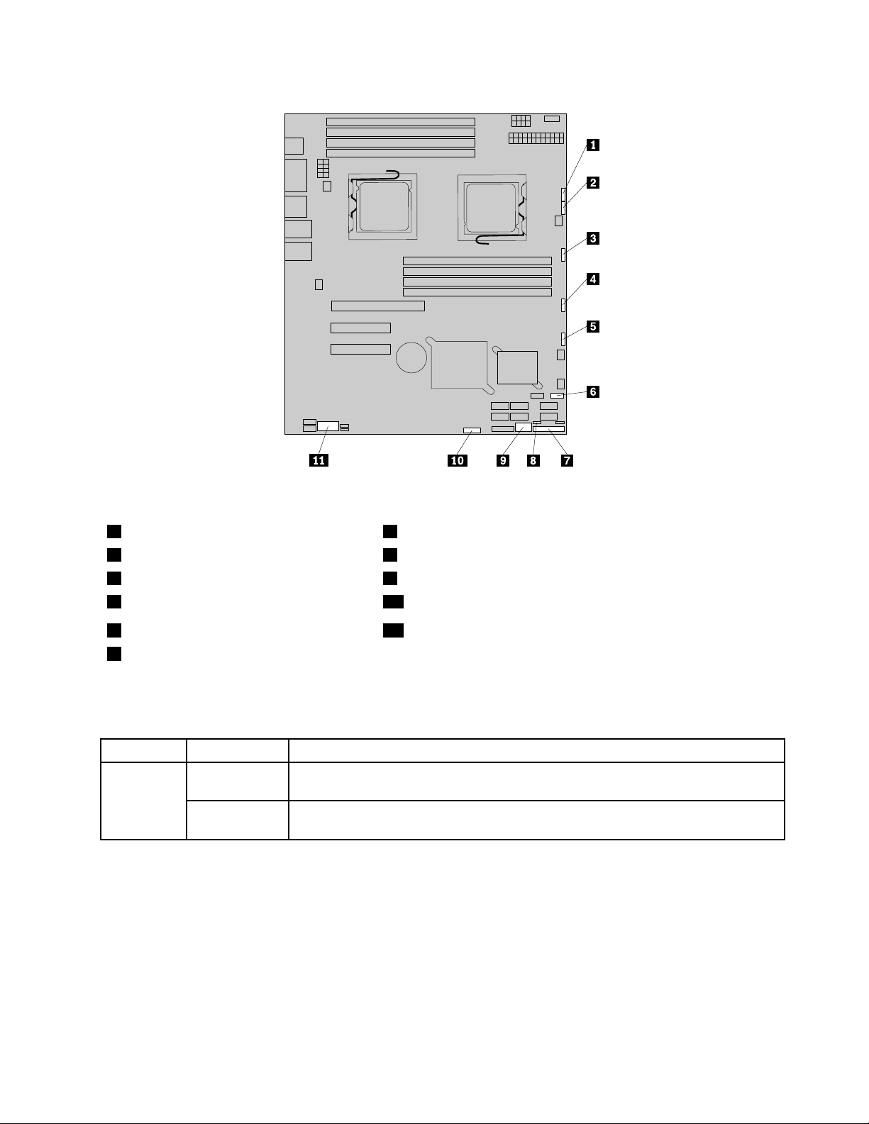
Figure6.Locatingotherconnectorsonthesystemboard
1J47(systemfan1connector)7J35(forfrontcontrolcable)
2J48(systemfan2connector)8JP1(ClearCMOSjumper)
3J50(systemfan3connector)9USB2connector
4J56(systemfan4connector)10J45connector(fortheSGPIOconnectorofthe4–portSATAcable)
5J49(systemfan5connector)11JP8(COM2connector)
6J19(frontUSBconnector)
Thefollowingtableintroducesthejumperswitchesonthesystemboard.
Table9.Jumpersettings
JumperPositionDescription
JP1:Clear
Pins1-2
CMOS
Pins2-3
Thedefaultpositionatwhichthejumperisplacedonpins1-2duringthenormal
operationofthesystem.
Ifthejumperisplacedonpins2-3,whenthejumperismovedbacktothedefault
position,thesettingsofCMOSwillbeclearedautomaticallyatthenextstartup.
Note:BeforeclearingtheCMOS,turnofftheserveranddisconnectthepowercord.Movethejumperfrom
pins1-2topins2-3.Waitmorethanveminutesandthenmovethejumperbacktothenormalposition
(pins1-2)toclearCMOS.
Chapter4.Locatingparts,controls,LEDs,andconnectors15
Page 26
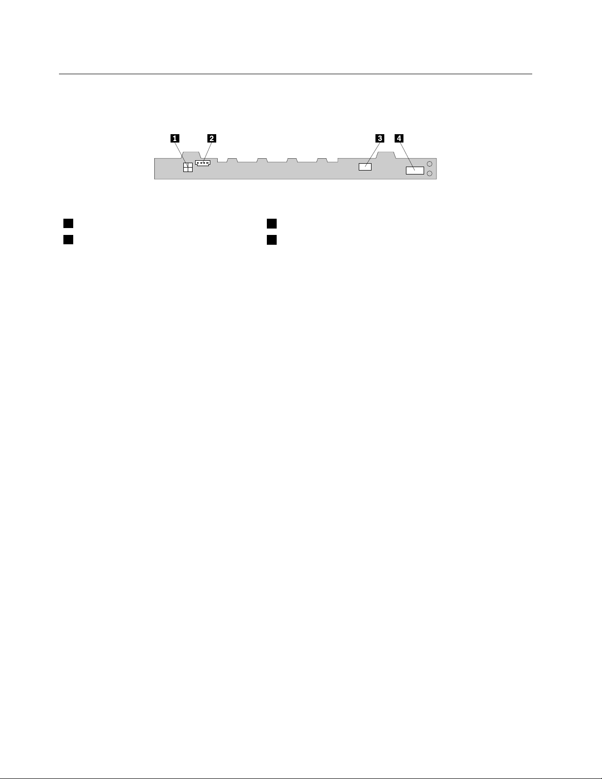
Locatingconnectorsonthebackplane
Thefollowingillustrationshowstheconnectorlocationsonthebackplane.
Figure7.Backplaneconnectorlocations
1Powerconnector2
2Powerconnector1
3Opticaldrivepowerconnector
4Mini-SASsignalcableconnector
16ThinkServerInstallationandUserGuide
Page 27

Chapter5.Installing,removing,orreplacinghardware
Thischapterprovidesinstructionsonhowtoinstall,remove,orreplacehardwareforyourserver.
Thischaptercontainsthefollowingtopics:
•“Guidelines”onpage17
•“Removingtheservercover”onpage19
•“Installing,removing,orreplacingoptionalhardwaredevices”onpage20
•“Installing,removing,orreplacinghardwaredevices”onpage38
•“Completingthepartsreplacement”onpage64
Guidelines
Thissectionprovidessomeguidelinesthatyoushouldreadandunderstandbeforeusingyourserver.
Basicguidelines
Beforeyouusetheserver,besuretoreadandunderstandthefollowingguidelines:
•BesuretoreadandunderstandtheSafetyInformationandtheWarrantyandSupportInformationonthe
documentationDVDthatcomeswithyourproduct,and“Guidelines”onpage17
helpyouworksafely.T oobtainacopyofthepublications,goto:
http://www.lenovo.com/support
•Whenyouinstallyournewserver,taketheopportunitytodownloadandapplythemostrecentrmware
updates.Thisstepwillhelpyoutoensurethatanyknownissuesareaddressedandtheserverisreadyto
functionatoptimalperformance.Todownloadrmwareupdatesforyourserver,dothefollowing:
1.Gotohttp://www.lenovo.com/support.
2.ClickDownload&Drivers➙ThinkServerandthenfollowtheinstructionsontheWebpageto
downloadrmwareupdatesforyourserver.
•Observegoodhousekeepingintheareawhereyouareworking.Putremovedcoversandotherparts
inasafeplace.
•Ifyoumustturnontheserverwhiletheservercoverisremoved,makesurethatnooneisneartheserver
andthatnotoolsorotherobjectshavebeenleftinsidetheserver.
•Donotattempttoliftanobjectthatyouthinkistooheavyforyou.Ifyouhavetoliftaheavyobject,
observethefollowingprecautions:
.Theseinformationwill
–Makesurethatyoucanstandsafelywithoutslipping.
–Distributetheweightoftheobjectequallybetweenyourfeet.
–Useaslowliftingforce.Nevermovesuddenlyortwistwhenyouliftaheavyobject.
–Toavoidstrainingthemusclesinyourback,liftbystandingorbypushingupwithyourlegmuscles.
•Makesurethatyouhaveanadequatenumberofproperlygroundedelectricaloutletsfortheserver,
monitor,andotherdevices.
•Backupallimportantdatabeforeyoumakechangestodrives.
•Haveasmallat-bladescrewdriveravailable.
•ToviewtheerrorLEDsonthesystemboardandinternalcomponents,leavetheserverconnectedto
power.
©CopyrightLenovo2010,2011
17
Page 28
•Y oudonothavetoturnofftheservertoinstallorreplacehot-swapfans,redundanthot-swapacpower
supplies,orhot-plugUSBdevices.However,youmustturnofftheserverbeforeperforminganystepsthat
involveinstalling,removing,orreplacingadaptercablesornon-hot-swapoptionaldevicesorcomponents.
•Aftercompletinganyinstallation,removal,orreplacementprocedure,reinstallallsafetyshields,guards,
labels,andgroundwires.
•Foralistofsupportedoptionaldevicesfortheserver,gotohttp://www.lenovo.com/thinkserver.
•Whenworkinginsidetheserver,youmightndsometaskseasierifyoulaytheserveronitsside.
Systemreliabilityguidelines
Tohelpensurepropercoolingandsystemreliability,makesurethatyoufollowtheseguidelines:
•EverydrivebayhasaninternaldriveinstalledoranElectroMagneticCompatibility(EMC)shieldinstalled.
•Iftheserverhasredundantpower,everypowersupplybayhasapowersupplyassemblyinstalled.
•Leaveadequatespacearoundtheservertomakesurethattheservercoolingsystemworkswell.
•Properlyroutethecables.Forsomeoptions,suchasPCIcards,followthecablinginstructionsthat
comewiththeoptions.
•Makesurethatyoureplaceafailingfanwithin48hours.
•Whenreplacingahot-swapdrive,installthenewhot-swapdrivewithintwominutesofremoval.
•Donotremoveanyairductorairbafeswhiletheserverisrunning.Operatingtheserverwithoutthe
airductorairbafesmightcausethemicroprocessortooverheat.
•Thesecondmicroprocessorsocketalwayscontainseitheramicroprocessorsocketcoverora
microprocessor.
Handlingstatic-sensitivedevices
Attention:
Donotopenthestatic-protectivepackagecontainingthenewpartuntilthedefectiveparthasbeenremovedfromthe
serverandyouarereadytoinstallthenewpart.Staticelectricity,althoughharmlesstoyou,canseriouslydamage
servercomponentsandparts.
Whenyouhandleserverpartsandcomponents,taketheseprecautionstoavoidstatic-electricitydamage:
•Limityourmovement.Movementcancausestaticelectricitytobuilduparoundyou.
•Wearanelectrostatic-dischargewriststrap,ifoneisavailable.
•Alwayscarefullyhandlethepartsandothercomponents(suchasPCIcards,memorymodules,system
boards,andmicroprocessors)byitsedgesoritsframe.Donottouchsolderjoints,pins,orexposed
circuitry.
•Preventothersfromtouchingthepartsandothercomputercomponents.
•Beforeyoureplaceanewpart,touchthestatic-protectivepackagecontainingthenewparttoametal
expansion-slotcoverorotherunpaintedmetalsurfaceontheserverforatleasttwoseconds.This
reducesstaticelectricityfromthepackageandyourbody.
•Removethenewpartfromthestatic-protectivepackageanddirectlyinstallitintheserverwithout
placingitonanyothersurface.Ifitishardforyoutodothisinyourspecicsituation,placethe
static-protectivepackageofthenewpartonasmooth,levelsurface,andthenplacethenewparton
thestatic-protectivepackage.
•Donotplacethepartontheservercoverorothermetalsurface.
•Takeadditionalcarewhenhandlingdevicesduringcoldweather.Heatingreducesindoorhumidity
andincreasesstaticelectricity.
18ThinkServerInstallationandUserGuide
Page 29
Workinginsidetheserverwiththepoweron
Attention:
Staticelectricitythatisreleasedtointernalservercomponentswhentheserveristurnedonmightcausetheserverto
halt,whichmightresultinthelossofdata.Toavoidthispotentialproblem,alwaysuseanelectrostatic-dischargewrist
straporothergroundingsystemwhenyouworkinsidetheserverwiththepoweron.
Theserversupportshot-swapdevicesandisdesignedtooperatesafelywhileitisturnedonandthecoveris
removed.Followtheseguidelineswhenyouworkinsidetheserverwiththepoweron:
•Avoidwearingloose-ttingclothingonyourforearms.Buttonlong-sleevedshirtsbeforeworkinginside
theserver;donotwearcufflinkswhileyouareworkinginsidetheserver.
•Donotallowyournecktieorscarftohanginsidetheserver.
•Removejewelry,suchasbracelets,necklaces,rings,andloose-ttingwristwatches.
•Removeitemsfromyourshirtpocket,suchaspensandpencils.Theseitemsmightfallintotheserveras
youleanoverit.
•Avoiddroppinganymetallicobjectsintotheserver,suchaspaperclips,hairpins,andscrews.
Removingtheservercover
Attention:Donotopenyourserverorattemptanyrepairbeforereadingandunderstandingthe“Safetyinformation”
onpageiiiand“Guidelines”onpage17.
Thissectionprovidesinstructionsonhowtoremovetheservercover.
Attention:Forpropercoolingandairow,installtheservercoverbeforeturningontheserver.Operatingthe
serverformorethan30minuteswiththeservercoverremovedmightdamageservercomponents.
Toremovetheservercover,dothefollowing:
1.Removeallmediafromthedrives.Then,turnoffallattacheddevicesandtheserver.
2.Disconnectallpowercordsfromelectricaloutlets.
3.Disconnectthepowercord(s),Input/Output(I/O)cables,andallothercablesthatareconnectedto
theserver.
Chapter5.Installing,removing,orreplacinghardware19
Page 30
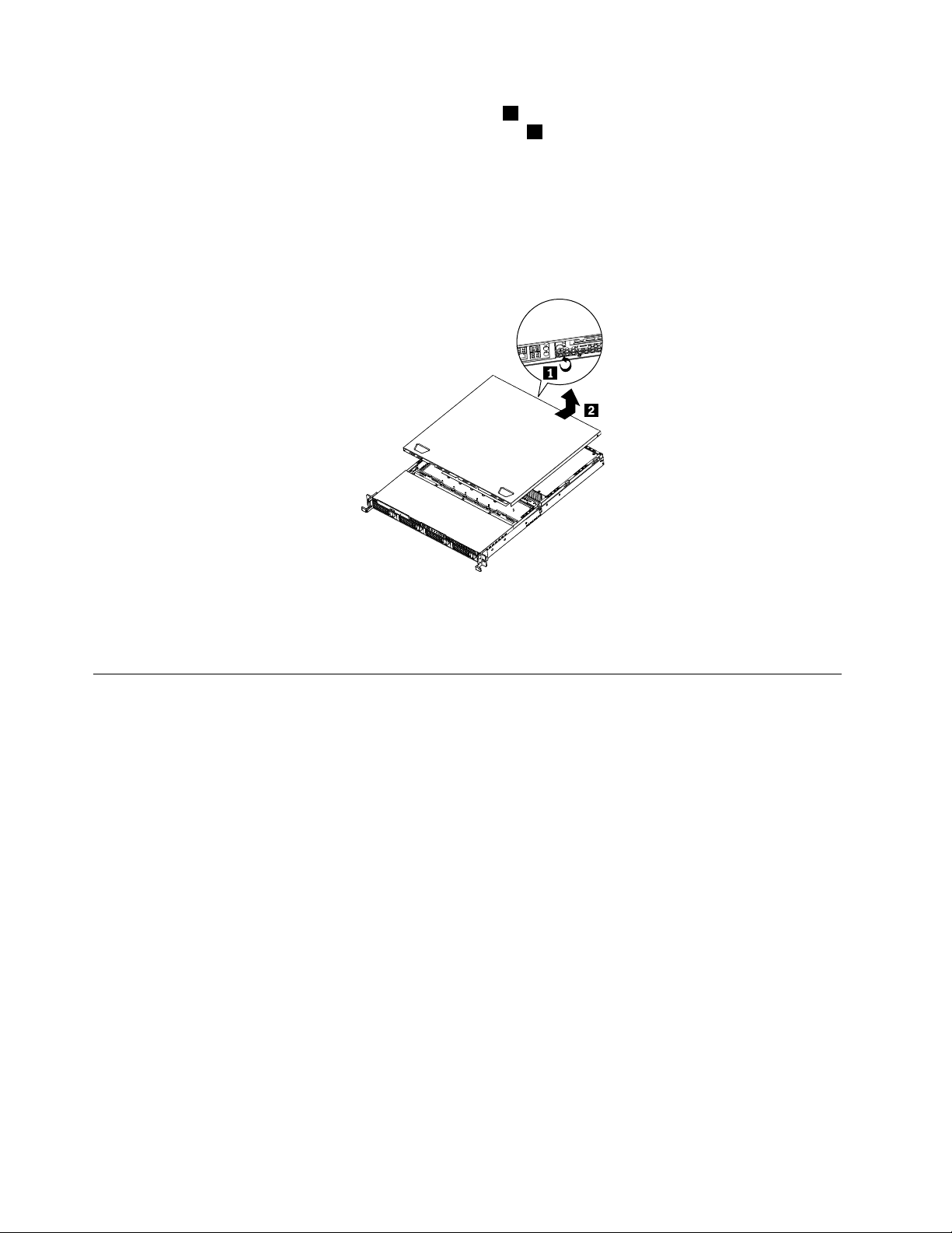
4.Loosenthethumbscrewintherearoftheservercover1.Then,slidetheservercovertotherearuntil
youcanliftituptocompletelyremoveitfromthechassis2.
Notes:
a.Thethumbscrewissecurelyinstalledandyouneedtouseatool,forexampleascrewdriver,to
loosenit.
b.Thethumbscrewisanintegratedpartoftheservercoveranditcannotberemovedfromtheserver
cover.
Figure8.Removingtheservercover
Toreinstalltheservercover,see“Installingtheservercover”onpage64.
Installing,removing,orreplacingoptionalhardwaredevices
Thissectionprovidesinstructionsonhowtoinstall,remove,orreplaceoptionalhardwaredevicesforyour
server.Youcanexpandthecapabilitiesofyourserverbyaddingmemorymodules,PCIcards,ordrives,
andmaintainyourserverbyreplacingthefailingoptionalhardwaredevices.Ifyouarereplacinganoptional
hardwaredevice,performtheremovalprocedureandthenperformtheinstallationprocedurefortheoptional
hardwaredevicethatyouwanttoreplace.
Installingorremovingamemorymodule
Thissectionprovidesinstructionsonhowtoinstallorremoveamemorymodule.Foralistofthesupported
memorymodulesforyourserver,gotohttp://www.lenovo.com/thinkserver.OntheThinkServersystems
page,clickProducts➙Options➙ThinkServerMemory.
Memorymoduleinstallationrules
YourserverhaseightmemoryslotsforinstallingorreplacingDDR3SDRAMDIMMsthatprovideuptoa
maximumof64GBofsystemmemory.
Thefollowingtablesprovideinformationaboutthememorymoduleinstallationrulesthatyoushould
considerwheninstallingamemorymodule.The“X”markindicatesthesuggestedmemoryslot(s)into
whichthememorymodule(s)shouldbeinstalledindifferentsituations.Thenumber,forexample1,2,or3,
indicatestheinstallationsequence.See“Locatingpartsonthesystemboard”onpage13
variousmemoryslots.
toidentifythe
20ThinkServerInstallationandUserGuide
Page 31

Note:Allmemorymoduletypesandcapacitiesmustbeconsistent.
Table10.DIMMinstallationruleswhenasinglemicroprocessor(CPU0)isinstalled
DIMMslotOneDIMMTwoDIMMsThreeDIMMsFourDIMMs
CPU0DIMMCHA1
CPU0DIMMCHA0
CPU0DIMMCHB0
CPU0DIMMCHC0
Note:InstallingDIMMsonchannelAandchannelBofCPU0shouldenableChannelMirroringMode.Thismode
requiresthatyouinstalltheDIMMsinpair,andtheDIMMinstallationforChannelMirroringModeisoneDIMMon
CPU0DIMMCHA0andoneDIMMonCPU0DIMMCHB0whenasinglemicroprocessor(CPU0)isinstalled.
Table11.DIMMinstallationruleswhentwomicroprocessors(CPU0andCPU1)areinstalled
DIMMslotTwoDIMMsFourDIMMsSixDIMMsEightDIMMs
CPU0DIMMCHA1
CPU0DIMMCHA0
CPU0DIMMCHB0
CPU0DIMMCHC0
CPU1DIMMCHA1
CPU1DIMMCHA0
CPU1DIMMCHB0
CPU1DIMMCHC0
Note:FortheChannelMirroringMode,itrequiresthatyouinstalltheDIMMsinpair,andtheDIMMinstallationfor
ChannelMirroringModewhentwomicroprocessors(CPU0andCPU1)areinstalledisshownbelow.Followthis
sequenceratherthanthesequencelistedaboveifyouwanttousetheChannelMirroringMode.
1.Pair1:installaDIMMonCPU0DIMMCHA0andtheninstallaDIMMonCPU0DIMMCHB0.
2.Pair2:installaDIMMonCPU1DIMMCHA0andtheninstallaDIMMonCPU1DIMMCHB0.
XX,1X,1X,1
X,2X,2X,2
X,3X,3
X,1X,1X,1X,1
X,3X,3X,3
X,5X,5
X,2X,2X,2X,2
X,4X,4X,4
X,6X,6
X,4
X,7
X,8
Installingamemorymodule
Attention:Donotopenyourserverorattemptanyrepairbeforereadingandunderstandingthe“Safetyinformation”
onpageiii
Thissectionprovidesinstructionsonhowtoinstallamemorymodule.
Toinstallamemorymodule,dothefollowing:
1.Removeallmediafromthedrivesandturnoffallattacheddevicesandtheserver.Then,disconnectall
2.Removetheservercover.See“Removingtheservercover”onpage19.
3.Locatetheappropriatememoryslotonthesystemboardintowhichyouwillinstallthememorymodule.
and“Guidelines”onpage17.
powercordsfromelectricaloutletsanddisconnectallcablesthatareconnectedtotheserver.
Tooptimizesystemperformance,followtherelatedmemorymoduleinstallationrulesandinstallthe
memorymoduleintoamemoryslotstartingwiththememorymodulefarthestfromthemicroprocessor.
See“Memorymoduleinstallationrules”onpage20
.
Chapter5.Installing,removing,orreplacinghardware21
Page 32

4.Opentheretainingclipsofthememoryslotintowhichyouwanttoinstallthememorymodule.
Figure9.Openingtheretainingclipsofthememoryslot
5.T ouchthestatic-protectivepackagethatcontainsthenewmemorymoduletoanyunpaintedmetal
surfaceontheoutsideoftheserver.Then,removethenewmemorymodulefromthepackage.
6.Positionthenewmemorymoduleoverthememoryslot.Makesurethatthenotch1onthenewmemory
moduleisalignedwiththekey2inthememoryslot.Then,pressthenewmemorymodulestraightdown
intothememoryslotuntiltheretainingclipscloseandthenewmemorymodulesnapsintoposition.
Note:Ifthereisagapbetweenthememorymoduleandtheretainingclips,thememorymodulehas
notbeencorrectlyinstalled.Opentheretainingclips,removethememorymodule,andthenreinstallit
intotheslot.
Figure10.Installingthememorymodule
Whattodonext:
•Toworkwithanotherpieceofhardware,gototheappropriatesection.
•Tocompletetheinstallation,goto“Completingthepartsreplacement”onpage64
Removingamemorymodule
Attention:Donotopenyourserverorattemptanyrepairbeforereadingandunderstandingthe“Safetyinformation”
onpageiii
Thissectionprovidesinstructionsonhowtoremoveamemorymodule.
Toremoveamemorymodule,dothefollowing:
22ThinkServerInstallationandUserGuide
and“Guidelines”onpage17.
.
Page 33

1.Removeallmediafromthedrivesandturnoffallattacheddevicesandtheserver.Then,disconnectall
powercordsfromelectricaloutletsanddisconnectallcablesthatareconnectedtotheserver.
2.Removetheservercover.See“Removingtheservercover”onpage19.
3.Locatethememoryslotwiththememorymodulethatyouwanttoremove.See“Locatingpartsonthe
systemboard”onpage13forthelocationsofthememoryslots.
4.Carefullyopentheretainingclipsoneachendofthememoryslotandthengraspthememorymodule
straightupbyitsedges.
Figure11.Removingthememorymodule
5.Ifyouareinstructedtoreturnthefailingmemorymodule,followallpackaginginstructionsanduseany
packagingmaterialsthataresuppliedtoyouforshipping.
Whattodonext:
•Toworkwithanotherpieceofhardware,gototheappropriatesection.
•Tocompletetheremovalprocedure,goto“Completingthepartsreplacement”onpage64
.
Removingorinstallinginternaldrives
Thissectionprovidesinstructionsonhowtoremoveorinstallinternaldrivesfortheserver.
See“Specications”onpage5forinformationaboutthetypesofinternaldrivesthattheserversupportsand
otherimportantinformation,andsee“Frontview”onpage9forthelocationsofthedrivebaysintheserver.
Wheninstallinganinternaldrive,besuretoconsiderthefollowinginformation:
•Makesurethatyouhaveallthecablesandotherequipmentthatisspeciedinthedocumentationthat
comeswiththedrive.
•Selectthedrivebayinwhichyouwanttoinstallthedrive.
•Checktheinstructionsthatcomewiththedrivetoseewhetheryouhavetosetanyswitchesorjumpers
onthedrive.IfyouareinstallingaSASdevice,besuretosettheSASIDforthatdevice.
•TheEMIintegrityandcoolingoftheserverareprotectedbyhavingallbays,PCIslots,andPCIExpress
slotscoveredoroccupied.Whenyouinstalladrive,PCIcard,orPCIExpresscard,savetheEMC
shieldandllerpanelfromthebay,PCIcardslot,orPCIExpresscardslotintheeventthatyoulater
removethedevice.
•Foralistofthesupportedharddiskdrivesforyourserver,gotohttp://www.lenovo.com/thinkserver.On
theThinkServersystemspage,clickProducts➙Options➙ThinkServerHardDrives.
Chapter5.Installing,removing,orreplacinghardware23
Page 34

Removingtheopticaldrive
Attention:Donotopenyourserverorattemptanyrepairbeforereadingandunderstandingthe“Safetyinformation”
onpageiiiand“Guidelines”onpage17.
Thissectionprovidesinstructionsonhowtoremovetheopticaldrive.
Toremovetheopticaldrive,dothefollowing:
1.Removeallmediafromthedrivesandturnoffallattacheddevicesandtheserver.Then,disconnectall
powercordsfromelectricaloutletsanddisconnectallcablesthatareconnectedtotheserver.
2.Removetheservercover.See“Removingtheservercover”onpage19.
3.Disconnectthepowercablefromtheopticaldrivepowerconnectoronthebackplane.See“Locating
connectorsonthebackplane”onpage16
4.DisconnectthesignalcablefromtheSATA5connectoronthesystemboard.See“Locatingpartson
thesystemboard”onpage13
.
5.Presstheretentiontab1andslidetheopticaldriveoutofthefrontoftheserver.
.
Figure12.Removingtheopticaldrive
6.Disconnectthepowercableandthesignalcablefromtherearoftheremovedopticaldrive.
24ThinkServerInstallationandUserGuide
Page 35

7.Removetheopticaldriveretentiontabbyremovingthetwoscrewsthatsecurethetab.Savethe
retentiontabtousewhenyouinstallanewopticaldrive.
Figure13.Removingtheopticaldriveretentiontab
8.Ifyouareinstructedtoreturntheremovedopticaldrive,followallpackaginginstructionsanduseany
packagingmaterialsthataresuppliedtoyouforshipping.
Whattodonext:
•Toworkwithanotherpieceofhardware,gototheappropriatesection.
•Tocompletetheremovalprocedure,goto“Completingthepartsreplacement”onpage64.
Installingtheopticaldrive
Attention:Donotopenyourserverorattemptanyrepairbeforereadingandunderstandingthe“Safetyinformation”
onpageiiiand“Guidelines”onpage17.
Thissectionprovidesinstructionsonhowtoinstalltheopticaldrive.
Toinstalltheopticaldrive,dothefollowing:
1.Ifyouarereplacingtheopticaldrive,makesurethat:
•Y ouhaveallthecablesandotherequipmentthatisspeciedinthedocumentationthatcomes
withthenewopticaldrive.
•Y ouhavecheckedtheinstructionsthatcomewiththenewopticaldrivetodeterminewhetheryou
mustsetanyswitchesorjumpersinthedrive.
•Y ouhaveremovedtheretentiontabfromtherearoftheoldopticaldriveandhaveitavailablefor
installationonthenewopticaldrive.
Note:Ifyouareinstallingadrivethatcontainsalaser,observethefollowingsafetyprecautions.
Statement3
CAUTION:
Whenlaserproducts(suchasCD-ROMs,DVDdrives,beropticdevices,ortransmitters)are
installed,notethefollowing:
•Donotremovethecovers.Removingthecoversofthelaserproductcouldresultinexposure
tohazardouslaserradiation.Therearenoserviceablepartsinsidethedevice.
•Useofcontrolsoradjustmentsorperformanceofproceduresotherthanthosespeciedherein
mightresultinhazardousradiationexposure.
Chapter5.Installing,removing,orreplacinghardware25
Page 36

DANGER
SomelaserproductscontainanembeddedClass3AorClass3Blaserdiode.Notethefollowing.
Laserradiationwhenopen.Donotstareintothebeam,donotviewdirectlywithoptical
instruments,andavoiddirectexposuretothebeam.
2.T ouchthestatic-protectivepackagethatcontainsthenewopticaldrivetoanyunpaintedmetalsurface
ontheserver.Then,removetheopticaldrivefromthepackageandplaceitonastatic-protective
surface.
3.Followtheinstructionsthatcomewiththeopticaldrivetosetjumpersorswitches,ifthereareany.
4.Installthetwoscrewstosecuretheretentiontabtotherearofthenewopticaldrive.Then,connectthe
signalcable
1andthepowercable2totherearofthenewopticaldrive.
Figure14.Installingtheretentiontabandconnectingthecables
26ThinkServerInstallationandUserGuide
Page 37

5.Routethecablesthroughthedrivebayholeinthefrontandthenslidetheopticaldriveintothedrive
bayuntilitsnapsintoposition.
Figure15.Installingtheopticaldrive
6.Connectthepowercabletotheopticaldrivepowerconnectoronthebackplane.See“Locating
connectorsonthebackplane”onpage16.
7.ConnectthesignalcabletotheSATA5connectoronthesystemboard.See“Locatingpartsonthe
systemboard”onpage13.
Whattodonext:
•Toworkwithanotherpieceofhardware,gototheappropriatesection.
•Tocompletetheinstallation,goto“Completingthepartsreplacement”onpage64
.
Removingahot-swapharddiskdrive
Attention:Donotopenyourserverorattemptanyrepairbeforereadingandunderstandingthe“Safetyinformation”
onpageiiiand“Guidelines”onpage17.
Thissectionprovidesinstructionsonhowtoremoveahot-swapharddiskdrive.Thissectionappliesonlyto
servermodelsthathavehot-swapharddiskdrivesinstalled.
Attention:Tomaintainpropersystemcooling,donotoperatetheserverformorethan10minuteswithout
eitheradriveorallerpanelinstalledineachdrivebay.
Toremoveahot-swapharddiskdrive,dothefollowing:
Note:Youdonothavetoturnofftheserverwhenremovingahot-swapharddiskdrive.
Chapter5.Installing,removing,orreplacinghardware27
Page 38

1.Rotatethedrivetrayhandle2oftheharddiskdrivetrayassembly1totheopenposition.Then,grasp
thehandleandpullthedrivetrayassemblywiththeharddiskdriveoutofthebay.
Figure16.Removingtheharddiskdrivetrayassemblywiththeharddiskdrive
2.Removethescrewsthatsecuretheharddiskdriveinthetray.Then,removetheharddiskdrive.
Figure17.Removinga3.5-inchharddiskdrive
28ThinkServerInstallationandUserGuide
Page 39

3.Ifyouareinstructedtoreturntheremovedharddiskdrive,followallpackaginginstructionsanduseany
packagingmaterialsthataresuppliedtoyouforshipping.
Whattodonext:
•Toworkwithanotherpieceofhardware,gototheappropriatesection.
•Tocompletetheremovalprocedure,goto“Completingthepartsreplacement”onpage64.
Installingahot-swapharddiskdrive
Attention:Donotopenyourserverorattemptanyrepairbeforereadingandunderstandingthe“Safetyinformation”
onpageiiiand“Guidelines”onpage17.
Thissectionprovidesinstructionsonhowtoinstallahot-swapharddiskdrive.Thissectionappliesonlyto
servermodelsthatsupporthot-swapharddiskdrives.
Attention:Tomaintainpropersystemcooling,donotoperatetheserverformorethan10minuteswithout
eitheradriveorallerpanelinstalledineachdrivebay.
Notes:
1.Y oudonothavetoturnofftheserverfortheinstallationofahot-swapharddiskdrive.
2.ThecablescomewiththeSATAharddiskdriveoptionkitwillnotbeusedinthisserver.
Toinstallahot-swapharddiskdrive,dothefollowing:
1.Rotatethedrivetrayhandle2oftheharddiskdrivetrayassembly1totheopenposition.Then,grasp
thehandleandpullthedrivetrayassemblyoutofthebay.
Figure18.Removingtheharddiskdrivetrayassembly
Chapter5.Installing,removing,orreplacinghardware29
Page 40

2.Removethescrewsthatsecuretheplasticllerandthenremovetheplasticller.
Figure19.Removingtheller
3.T ouchthestatic-protectivepackagethatcontainsthenewharddiskdrivetoanyunpaintedmetal
surfaceontheserver.Then,removetheharddiskdrivefromthepackageandplaceitona
static-protectivesurface.
4.Makesurethatthedrivetrayhandleisintheopenposition.
30ThinkServerInstallationandUserGuide
Page 41

5.Alignthescrewholesinbothsidesoftheharddiskdrivewiththecorrespondingholesinthetray.Then,
installthescrewstosecuretheharddiskdriveinthetray.
Figure20.Installinga3.5-inchharddiskdrive
6.Keepthehandleontheharddiskdrivetrayassemblyfullyopen,slidethetraywiththeharddiskdrive
intothecorrespondingmountingpointofthehot-swapharddiskdrivebay1,andthenslightlypress
thehandletolockthetrayintoplace2.
7.ChecktheharddiskdrivestatusLEDstomakesurethattheharddiskdriveisoperatingcorrectly.You
mighthavetorestarttheserverforthedrivetoberecognized.IftheamberharddiskdrivestatusLED
foradriveislitcontinuously,itindicatesthatthedriveisfaultyandmustbereplaced;ifthegreenhard
diskdriveactivityLEDisashing,thisindicatesthatthedriveisbeingaccessed.
Note:IftheserverisconguredforRAIDoperationusingaRAIDcontroller,youmighthaveto
recongurethediskarraysafteryoureplaceharddiskdrives.
Chapter5.Installing,removing,orreplacinghardware31
Page 42

Whattodonext:
•Toworkwithanotherpieceofhardware,gototheappropriatesection.
•Tocompletetheinstallation,goto“Completingthepartsreplacement”onpage64.
Installingorremovingtherisercard
Thissectionprovidesinstructionsonhowtoinstallorremovetherisercard.
Installingtherisercard
Attention:Donotopenyourserverorattemptanyrepairbeforereadingandunderstandingthe“Safetyinformation”
onpageiiiand“Guidelines”onpage17.
Thissectionprovidesinstructionsonhowtoinstalltherisercard.TherisercardhasaPCIcardinstalledonit.
Toinstalltherisercard,dothefollowing:
Note:Useanydocumentationthatcomeswiththerisercardandfollowthoseinstructionsinadditionto
theinstructionsinthissection.
1.Removeallmediafromthedrivesandturnoffallattacheddevicesandtheserver.Then,disconnectall
powercordsfromelectricaloutletsanddisconnectallcablesthatareconnectedtotheserver.
2.Removetheservercover.See“Removingtheservercover”onpage19.
3.LocatetheappropriatePCIslotonthesystemboardforinstallingtherisercard.See“Locatingpartson
thesystemboard”onpage13
4.T ouchthestatic-protectivepackagethatcontainstherisercardtoanyunpaintedmetalsurfaceonthe
server.Then,removetherisercardfromthestatic-protectivepackage.
.
32ThinkServerInstallationandUserGuide
Page 43

5.Presstherisercard(mighthavingaPCIcardinstalled)downintotheappropriatePCIcardslotonthe
systemboard.Then,closetheretentiontabtosecurethePCIcard(installedontherisercard)andthen
installthefasteningscrewtosecuretherisercardinplace.
Note:TherisercardmighthaveaPCIcardalreadyinstalledonit.CarefullytthePCIcardintothe
server.
Figure21.Installingtherisercard
Whattodonext:
•Toworkwithanotherpieceofhardware,gototheappropriatesection.
•Tocompletetheinstallation,goto“Completingthepartsreplacement”onpage64
Removingtherisercard
Attention:Donotopenyourserverorattemptanyrepairbeforereadingandunderstandingthe“Safetyinformation”
onpageiii
ThissectionprovidesinstructionsonhowtoremovetherisercardwithaPCIcardinstalled.
Toremovetherisercard,dothefollowing:
and“Guidelines”onpage17.
Chapter5.Installing,removing,orreplacinghardware33
.
Page 44

Note:Useanydocumentationthatcomeswiththerisercardandfollowthoseinstructionsinadditionto
theinstructionsinthissection.
1.Removeallmediafromthedrivesandturnoffallattacheddevicesandtheserver.Then,disconnectall
powercordsfromelectricaloutletsanddisconnectallcablesthatareconnectedtotheserver.
2.Removetheservercover.See“Removingtheservercover”onpage19.
3.DisconnectanycablesfromthePCIcardoranycablesthatimpedeaccesstotherisercard.
4.OpentheretentiontabthatsecuresthePCIcard,whichisinstalledontherisercard.
Figure22.Openingtheretentiontab
34ThinkServerInstallationandUserGuide
Page 45

5.Removethefasteningscrewthatsecurestherisercard1andlifttherisercardstraightupbyits
edgestoremoveit2.
Figure23.Removingtherisercard(withaPCIcardinstalled)
Whattodonext:
•Toworkwithanotherpieceofhardware,gototheappropriatesection.
•Tocompletetheremovalprocedure,goto“Completingthepartsreplacement”onpage64.
InstallingorremovingaPCIcard
ThissectionprovidesinstructionsonhowtoinstallorremoveaPCIcard.
InstallingaPCIcard
Attention:Donotopenyourserverorattemptanyrepairbeforereadingandunderstandingthe“Safetyinformation”
onpageiii
ThissectionprovidesinstructionsonhowtoinstallaPCIcard.
ToinstallaPCIcard,dothefollowing:
Note:UseanydocumentationthatcomeswiththePCIcardandfollowthoseinstructionsinadditionto
theinstructionsinthissection.
1.Removeallmediafromthedrivesandturnoffallattacheddevicesandtheserver.Then,disconnectall
and“Guidelines”onpage17.
powercordsfromelectricaloutletsanddisconnectallcablesthatareconnectedtotheserver.
Chapter5.Installing,removing,orreplacinghardware35
Page 46

2.Removetheservercover.See“Removingtheservercover”onpage19.
3.Removetherisercard.See“Removingtherisercard”onpage33.
4.InstallthePCIcardintotheslotontherisercard.
Figure24.InstallingaPCIcardintotheslotontherisercard
5.InstalltherisercardintoanappropriatePCIcardslotonthesystemboard.See“Installingtheriser
card”onpage32
.
6.ConnectanycablestothePCIcard.
Whattodonext:
•Toworkwithanotherpieceofhardware,gototheappropriatesection.
•Tocompletetheinstallation,goto“Completingthepartsreplacement”onpage64.
RemovingaPCIcard
Attention:Donotopenyourserverorattemptanyrepairbeforereadingandunderstandingthe“Safetyinformation”
onpageiiiand“Guidelines”onpage17.
ThissectionprovidesinstructionsonhowtoremoveaPCIcard.
ThePCIcardisinstalledontherisercard.ToremoveaPCIcard,dothefollowing:
Note:UseanydocumentationthatcomeswiththePCIcardandfollowthoseinstructionsinadditionto
theinstructionsinthissection.
1.Removeallmediafromthedrivesandturnoffallattacheddevicesandtheserver.Then,disconnectall
powercordsfromelectricaloutletsanddisconnectallcablesthatareconnectedtotheserver.
2.Removetheservercover.See“Removingtheservercover”onpage19.
3.DisconnectanycablesfromthePCIcardoranycablesthatimpedeaccesstotherisercard.
4.RemovetherisercardtogetherwiththeinstalledPCIcard.See“Removingtherisercard”onpage33.
36ThinkServerInstallationandUserGuide
Page 47

5.RemovethePCIcardfromthePCIcardslotontherisercard.
Figure25.RemovingthePCIcardfromtherisercard
IfyouareinstructedtoreturnthePCIcard,followallpackaginginstructionsanduseanypackagingmaterials
thataresuppliedtoyouforshipping.
Whattodonext:
•Toworkwithanotherpieceofhardware,gototheappropriatesection.
•Tocompletetheremovalprocedure,goto“Completingthepartsreplacement”onpage64
.
RemovingorinstallingtheEthernetcard
ThissectionprovidesinstructionsonhowtoremoveorinstalltheEthernetcard.
RemovingtheEthernetcard
Attention:Donotopenyourserverorattemptanyrepairbeforereadingandunderstandingthe“Safetyinformation”
onpageiiiand“Guidelines”onpage17.
ThissectionprovidesinstructionsonhowtoremovetheEthernetcard.
TheEthernetcardisinstalledontherisercard.ToremovetheEthernetcard,dothefollowing:
Note:UseanydocumentationthatcomeswiththeEthernetcardandfollowthoseinstructionsinadditionto
theinstructionsinthissection.
1.Removeallmediafromthedrivesandturnoffallattacheddevicesandtheserver.Then,disconnectall
powercordsfromelectricaloutletsanddisconnectallcablesthatareconnectedtotheserver.
2.Removetheservercover.See“Removingtheservercover”onpage19.
3.Disconnectanycablesthatimpedeaccesstotherisercard.
4.RemovetherisercardtogetherwiththeinstalledEthernetcard.See“Removingtherisercard”on
page33
5.Referto“RemovingaPCIcard”onpage36andfollowthoseinstructionstoremovetheEthernet
cardfromtherisercard.
6.IfyouareinstructedtoreturntheEthernetcard,followallpackaginginstructionsanduseanypackaging
materialsthataresuppliedtoyouforshipping.
.
Whattodonext:
•Toworkwithanotherpieceofhardware,gototheappropriatesection.
Chapter5.Installing,removing,orreplacinghardware37
Page 48

•Tocompletetheremovalprocedure,goto“Completingthepartsreplacement”onpage64.
InstallingtheEthernetcard
Attention:Donotopenyourserverorattemptanyrepairbeforereadingandunderstandingthe“Safetyinformation”
onpageiii
ThissectionprovidesinstructionsonhowtoinstalltheEthernetcardandhowtoinstalltheEthernetcard
driveronWindowsoperatingsystems.
ToinstalltheEthernetcard,dothefollowing:
1.Removeallmediafromthedrivesandturnoffallattacheddevicesandtheserver.Then,disconnectall
2.Removetheservercover.See“Removingtheservercover”onpage19.
3.T ouchthestatic-protectivepackagethatcontainstheEthernetcardtoanyunpaintedsurfaceonthe
4.See“InstallingaPCIcard”onpage35andfollowthoseinstructionstoinstalltheEthernetcard.
Whattodonext:
•Toworkwithanotherpieceofhardware,gototheappropriatesection.
•Tocompletetheinstallation,goto“Completingthepartsreplacement”onpage64
OnLinuxoperatingsystems,youdonotneedtoinstallanydevicedriverfortheEthernetcard;onWindows
operatingsystems,youneedtoinstallthedevicedriverfortheEthernetcard.Toinstallthedevicedriver
onWindowsoperatingsystems,dothefollowing:
1.Saveanyopendocumentsandexitallapplications.
2.InserttheThinkServerEasyStartupDVDthatcamewithyourserverintotheDVDdrive.
and“Guidelines”onpage17.
powercordsfromelectricaloutletsanddisconnectallcablesthatareconnectedtotheserver.
outsideoftheserver.Then,removetheEthernetcardfromthepackage.
.
Note:YoudonotneedtousethedriverdiscthatcamewiththeEthernetcard.
3.Right-clickMyComputerandselectProperties.TheSystemPropertieswindowopens.
4.OntheHardwaretab,clicktheDeviceManagerbutton.TheDeviceManagerwindowopens.
5.ExpandtheNetworkadaptersandthenright-clickoneoftheEthernetcards(PRO/1000PTorthe
yellowquestionmark).
6.SelectUpdateDriver ....TheHardwareUpdateWizardprogramopens.
7.SelectInstallthesoftwareautomatically(Recommended)andclickNexttocontinue.
8.Followtheinstructionsonthescreen.
Installing,removing,orreplacinghardwaredevices
Thissectionprovidesinstructionsonhowtoinstall,remove,orreplacehardwaredevicesforyourserver.
Youcanmaintainyourserverbyreplacingthefailinghardwaredevices.Ifyouarereplacingahardware
device,performtheremovalprocedureandthenperformtheinstallationprocedureforthehardwaredevice
thatyouwanttoreplace.
Removingorinstallingthesystemboardbattery
Thissectionprovidesinstructionsonhowtoremoveorinstallthesystemboardbattery.
38ThinkServerInstallationandUserGuide
Page 49

Removingthesystemboardbattery
Attention:Donotopenyourserverorattemptanyrepairbeforereadingandunderstandingthe“Safetyinformation”
onpageiiiand“Guidelines”onpage17.
Thissectionprovidesinstructionsonhowtoremovethesystemboardbattery.
Toremovethesystemboardbattery,dothefollowing:
1.Removeallmediafromthedrivesandturnoffallattacheddevicesandtheserver.Then,disconnectall
powercordsfromelectricaloutletsanddisconnectallcablesthatareconnectedtotheserver.
2.Removetheservercover.See“Removingtheservercover”onpage19.
3.Locatethebatteryonthesystemboard.See“Locatingpartsonthesystemboard”onpage13.
4.Removethesystemboardbattery.
Figure26.Removingthesystemboardbattery
5.Disposeofthebatteryasrequiredbylocalordinancesorregulations.
Whattodonext:
•Toinstallanewsystemboardbattery,see“Installingthesystemboardbattery”onpage39.
•Toworkwithanotherpieceofhardware,gototheappropriatesection.
Installingthesystemboardbattery
Attention:Donotopenyourserverorattemptanyrepairbeforereadingandunderstandingthe“Safetyinformation”
onpageiiiand“Guidelines”onpage17.
Thissectionprovidesinstructionsonhowtoinstallthesystemboardbattery.
Besuretoconsiderthefollowinginformationwhenyoureplacethebatteryintheserver:
•Y oumustreplacethebatterywithalithiumbatteryofthesametypefromthesamemanufacturer.
•Afteryoureplacethesystemboardbattery,youmustreconguretheserverandresetthesystemdate
andtime.
•Toavoidpossibledanger,readandfollowthefollowingsafetystatement.
Statement2
CAUTION:
Whenreplacingthelithiumbattery,useonlyPartNumber33F8354oranequivalenttypebattery
recommendedbythemanufacturer.Ifyoursystemhasamodulecontainingalithiumbattery,replace
itonlywiththesamemoduletypemadebythesamemanufacturer.Thebatterycontainslithiumand
canexplodeifnotproperlyused,handled,ordisposedof.Donot:
Chapter5.Installing,removing,orreplacinghardware39
Page 50

•Throworimmerseintowater
•Heattomorethan100°C(212°F)
•Repairordisassemble
Toinstallthesystemboardbattery,dothefollowing:
Note:Followanyspecialhandlingandinstallationinstructionsthatcomewiththereplacementbattery.
1.Holdthesystemboardbattery1andpositiononesideofthebatteryintoitssocket.Then,pressthe
othersideofthebatteryuntilitsnapsintoplace.
Figure27.Installingthesystemboardbattery
2.Makesurethatthebatteryclipholdsthebatterysecurely.
Whattodonext:
•Toworkwithanotherpieceofhardware,gototheappropriatesection.
•Tocompletetheinstallation,goto“Completingthepartsreplacement”onpage64.Youneedtousethe
SetupUtilityprogramandresettheconguration,suchasthesystemdateandtimeandpasswords.See
“StartingtheSetupUtilityprogram”onpage68
fordetails.
RemovingorinstallingtheRAIDcontroller
ThissectionprovidesinstructionsonhowtoremoveorinstalltheRAIDcontroller.
RemovingtheRAIDcontroller
Attention:Donotopenyourserverorattemptanyrepairbeforereadingandunderstandingthe“Safetyinformation”
onpageiii
ThissectionprovidesinstructionsonhowtoremovetheRAIDcontrollerinstalledinyourserver.
Notes:
1.UseanydocumentationthatcomeswiththeRAIDcontrollerandfollowthoseinstructionsinadditionto
2.Whenyoudisconnectthepowersourcefromtheserver,youlosetheabilitytoviewtheLEDsbecause
TheRAIDcontrollerisinstalledontherisercard.ToremovetheRAIDcontroller,dothefollowing:
1.Removeallmediafromthedrivesandturnoffallattacheddevicesandtheserver.Then,disconnectall
2.Removetheservercover.See“Removingtheservercover”onpage19.
3.Pressthetabsonbothsidesoftheconnectoronthesignalcabletowardseachotherandremovethe
and“Guidelines”onpage17.
theinstructionsinthissection.
theLEDsarenotlitwhenthepowersourceisremoved.Beforeyoudisconnectthepowersource,make
anoteofwhichLEDsarelit,includingtheLEDsthatarelitonthefrontcontrolpanel.
powercordsfromelectricaloutletsanddisconnectallcablesthatareconnectedtotheserver.
cablefromtheRAIDcontroller.
40ThinkServerInstallationandUserGuide
Page 51

4.DisconnectanyothercablesfromtheRAIDcontrolleroranycablesthatimpedeaccesstotherisercard.
5.RemovetherisercardtogetherwiththeinstalledRAIDcontroller.See“Removingtherisercard”on
page33.
6.Referto“RemovingaPCIcard”onpage36andfollowthoseinstructionstoremovetheRAIDcontroller
fromtherisercard.
Note:DependingonyourRAIDcontroller,ifnecessary,removetheRAIDbatteryfromtheRAID
controllerbyremovingthescrewsthatsecurethebatteryonthecontrolleranddisconnectinganycables.
7.IfyouareinstructedtoreturntheRAIDcontroller,followallpackaginginstructionsanduseany
packagingmaterialsthataresuppliedtoyouforshipping.
Whattodonext:
•Toworkwithanotherpieceofhardware,gototheappropriatesection.
•Tocompletetheremovalprocedure,goto“Completingthepartsreplacement”onpage64.
InstallingtheThinkServer8708ELPSASRAIDAdapter
Attention:Donotopenyourserverorattemptanyrepairbeforereadingandunderstandingthe“Safetyinformation”
onpageiii
ThissectionprovidesinstructionsonhowtoinstalltheThinkServer8708ELPSASRAIDAdapter(hereafter
referredtoastheRAIDcontrollerwithinthissection).
ToinstalltheRAIDcontroller,dothefollowing:
and“Guidelines”onpage17.
Note:UseanydocumentationthatcomeswiththeRAIDcontrollerandfollowthoseinstructionsinaddition
totheinstructionsinthissection.
1.Removeallmediafromthedrivesandturnoffallattacheddevicesandtheserver.Then,disconnectall
powercordsfromelectricaloutletsanddisconnectallcablesthatareconnectedtotheserver.
2.Removetheservercover.See“Removingtheservercover”onpage19.
3.T ouchthestatic-protectivepackagethatcontainstheRAIDcontrollertoanyunpaintedsurfaceonthe
outsideoftheserver.Then,removetheRAIDcontrollerfromthepackage.
4.DependingonyourRAIDcontroller,youmightneedtoinstallaThinkServer8708ELPSASRAID
adapterbattery(hereafterreferredtoasthebatterycardassembly)ontheRAIDcontroller.Thebattery
cardassemblymountsdirectlytotheRAIDcontrollerthroughasmallboard-to-boardconnector
(daughtercard).
Notes:
a.ThebatterycardassemblyprotectstheintegrityofthecacheddataontheRAIDcontrollerby
providingbackuppowerupto72hoursinthecaseofacompleteacpowerfailureorabriefpower
outage.Ithasbuilt-infunctionalitytochargethebatterypackautomaticallyandtocommunicate
batterystatusinformationsuchasvoltage,temperature,andcurrenttoyourserver.Italsoprovides
aninexpensivealternativetousinganuninterruptiblepowersupply,andasecondleveloffault
tolerancewhenusedinconjunctionwithanuninterruptiblepowersupply.Formoreinformationabout
thebatterycardassembly,seeAppendixA“RAIDbatterycardassembly”onpage97
.
b.Thebatterycardassemblyoptionkitcontainsauserguide,thebatterycardassembly,andthree
Phillips-headscrews.Donotremovethebatterycardassemblyfromtheantistaticshipping
containeruntilyouarereadytoinstallit.Whenyouremovethebatterycardassemblyfromyour
server,placeitinitsoriginalcontainer.
c.ChecktheappropriatesupportWebsitesforthelatestupdatesforyourbasicinput/outputsystem
(BIOS)code,utilityprograms,devicedrivers,andothersoftwareapplications.Followtheinstructions
providedbyyourServiceProvidertodownloadandinstallupdates.
Chapter5.Installing,removing,orreplacinghardware41
Page 52

d.Itisrecommendedthatyoureplacethebatterypackonthebatterycardassemblyannuallyorafter
500rechargingcycles,whichevercomesrst.
e.Thetemperatureofthebatterycardassemblyisgenerally15-20°C(59-68°F)higherthanthe
ambienttemperatureduringfastcharge.Therefore,tocompleteafastchargecycle,theambient
temperatureshouldbelowerthan45°C(113°F).Iftheambienttemperatureexceeds45°C(113°F),
thefastchargecyclewillterminateprematurely,thuspreventingthebatterycardassemblyfrom
reachingafullychargedstate.
Attention:
•WhenattachingthebatterycardassemblytoaPCIExpressslot,centerthePhillips-headscrew
drivertoavoiddamagingthescrewheadanddonotover-tightenthescrewsasyoumightdamage
thebatterycardassembly.
•Thebatteryinthebatterycardassemblymustrechargeforatleastsixhoursduringfastcharge
undernormaloperatingconditions.
ToinstallthebatterycardassemblyontotheRAIDcontroller,dothefollowing:
42ThinkServerInstallationandUserGuide
Page 53

a.Notethetopviewandthebottomviewofthebatterycardassembly.Then,insertthebatterypack
harnessconnectorintothe5-pinJ3batterypackharnessconnectoronthebacksideofthebattery
cardassembly.Formoreinformation,refertothefollowingillustrations.
Figure28.Topviewofthebatterycardassembly
1Batterypackharness
Figure29.Bottomviewofthebatterycardassembly
1J3batterypackharnessconnector
2J1connector
3J2board-to-boardconnector
b.Withthefrontsideup,placetheRAIDcontrolleronaat,clean,static-freesurface.
Chapter5.Installing,removing,orreplacinghardware43
Page 54

c.HoldthebatterycardassemblywiththebatterysideupandtheJ2board-to-boardconnectorlining
upwiththeJ7BBUconnector1ontheRAIDcontroller.Carefullypressthebatterycardassembly
ontotheRAIDcontrollersothatthetwoconnectorsarermlyjoined.Then,securethebattery
cardassemblytotheRAIDcontrollerwiththethreescrewsandthestandoffsthatcomewiththe
batterycardassemblyaccessorykit.
Figure30.Installingthebatterycardassembly
1J7BBUconnector
5.See“InstallingaPCIcard”onpage35andfollowthoseinstructionstoinstalltheRAIDcontroller.
6.ConnecttheminiSASsignalcabletotheRAIDcontrollerandminiSASsignalcableconnectoronthe
backplane.See“Locatingconnectorsonthebackplane”onpage16
Note:Usethe440mm(17.32inches)miniSASsignalcable.
Figure31.ConnectingtheminiSASsignalcable
1Ports0-3
2Ports4-7(reservedforuse)
Whattodonext:
•Toworkwithanotherpieceofhardware,gototheappropriatesection.
•Tocompletetheinstallation,goto“Completingthepartsreplacement”onpage64
44ThinkServerInstallationandUserGuide
.
Page 55

InstallingtheThinkServer8708EM2RAIDAdapter
Attention:Donotopenyourserverorattemptanyrepairbeforereadingandunderstandingthe“Safetyinformation”
onpageiiiand“Guidelines”onpage17.
ThistopicprovidesinstructionsonhowtoinstalltheThinkServer8708EM2RAIDAdapter(hereafterreferred
toastheRAIDcontrollerwithinthistopic)andthebatterycardassemblyforthisRAIDcontroller.
ToinstalltheRAIDcontroller,dothefollowing:
Note:UseanydocumentationthatcomeswiththeRAIDcontrollerandfollowthoseinstructionsinaddition
totheinstructionsinthistopic.
1.Removeallmediafromthedrivesandturnoffallattacheddevicesandtheserver.Then,disconnectall
powercordsfromelectricaloutletsanddisconnectallcablesthatareconnectedtotheserver.
2.Removetheservercover.See“Removingtheservercover”onpage19.
3.Removetherisercardassembly.See“Removingtherisercard”onpage33.
4.T ouchthestatic-protectivepackagethatcontainstheRAIDcontrollertoanyunpaintedsurfaceonthe
outsideoftheserver.Then,removetheRAIDcontrollerfromthepackage.
5.DependingonyourRAIDcontroller,youmightneedtoinstallaThinkServer8708EM2RAIDAdapter
Battery(hereafterreferredtoasthebatterycardassembly)ontheRAIDcontroller.Thebattery
cardassemblymountsdirectlytotheRAIDcontrollerthroughasmallboard-to-boardconnector
(daughtercard).
Notes:
a.ThebatterycardassemblyprotectstheintegrityofthecacheddataontheRAIDcontrollerby
providingbackuppowerupto72hoursinthecaseofacompleteacpowerfailureorabriefpower
outage.Ithasbuilt-infunctionalitytochargethebatterypackautomaticallyandtocommunicate
batterystatusinformationsuchasvoltage,temperature,andcurrenttoyourserver.Italsoprovides
aninexpensivealternativetousinganuninterruptiblepowersupply,andasecondleveloffault
tolerancewhenusedinconjunctionwithanuninterruptiblepowersupply.Formoreinformationabout
thebatterycardassembly,seeAppendixA“RAIDbatterycardassembly”onpage97
b.Thebatterycardassemblyoptionkitcontainsauserguide,thebatterycardassembly,andthree
Phillips-headscrews.Donotremovethebatterycardassemblyfromtheantistaticshipping
containeruntilyouarereadytoinstallit.Whenyouremovethebatterycardassemblyfromyour
server,placeitinitsoriginalcontainer.
c.ChecktheappropriatesupportWebsitesforthelatestupdatesforyourbasicinput/outputsystem
(BIOS)code,utilityprograms,devicedrivers,andothersoftwareapplications.Followtheinstructions
providedbyyourServiceProvidertodownloadandinstallupdates.
d.Itisrecommendedthatyoureplacethebatterypackonthebatterycardassemblyannuallyorafter
500rechargingcycles,whichevercomesrst.
e.Thetemperatureofthebatterycardassemblyisgenerally15-20°C(59-68°F)higherthanthe
ambienttemperatureduringfastcharge.Therefore,tocompleteafastchargecycle,theambient
temperatureshouldbelowerthan45°C(113°F).Iftheambienttemperatureexceeds45°C(113°F),
thefastchargecyclewillterminateprematurely,thuspreventingthebatterycardassemblyfrom
reachingafullychargedstate.
.
Attention:
•WhenattachingthebatterycardassemblytoaPCIExpressslot,centerthePhillips-headscrew
drivertoavoiddamagingthescrewheadanddonotover-tightenthescrewsasyoumightdamage
thebatterycardassembly.
•Thebatteryinthebatterycardassemblymustrechargeforatleastsixhoursduringfastcharge
undernormaloperatingconditions.
Chapter5.Installing,removing,orreplacinghardware45
Page 56

ToinstallthebatterycardassemblyontotheRAIDcontroller,dothefollowing:
a.Notethetopviewandbottomviewofthebatterycardassembly.Then,insertthebatterypack
harnessconnectorintotheJ4batterypackharnessconnectoronthebacksideofthebatterycard
assembly.Formoreinformation,refertothefollowingillustrations.
Figure32.Topviewofthebatterycardassembly
1Batterypackharness
Figure33.Bottomviewofthebatterycardassembly
1J4batterypackharnessconnector
2J5board-to-boardconnector
3J2connector
b.Withthefrontsideup,placetheRAIDcontrolleronaat,clean,static-freesurface.
46ThinkServerInstallationandUserGuide
Page 57

c.HoldthebatterycardassemblywiththebatterysideupandtheJ5board-to-boardconnector
liningupwiththeJ10BBUconnector1ontheRAIDcontroller.Carefullypressthebatterycard
assemblyontotheRAIDcontrollersothatthetwoconnectorsarermlyjoined.Then,securethe
batterycardassemblytotheRAIDcontrollerwiththethreescrewsandthestandoffsthatcome
withthebatterycardassemblyaccessorykit.
Figure34.InstallingthebatterycardassemblyontotheRAIDcontroller
1J10BBUconnector
6.ConnecttheminiSASsignalcabletoports0-3ontheRAIDcontroller.
Note:Usethe400mm(15.75inches)miniSASsignalcable.
Figure35.ConnectingtheminiSASsignalcabletotheRAIDcontroller
1Ports0-3
2Ports4-7(reservedforuse)
Chapter5.Installing,removing,orreplacinghardware47
Page 58

7.InstalltheRAIDcontrollerintoanappropriatePCIcardslotontherisercardassembly.Then,install
thescrewtosecuretheRAIDcontrollerinplace.
Figure36.InstallingtheRAIDcontrollerintothePCIcardslotontherisercard
8.InstalltherisercardwiththeRAIDcontrollerintoanappropriatePCIcardslotonthesystemboard.
9.Connecttheotherendofthe400mm(15.75inches)miniSASsignalcabletotheminiSASsignalcable
connector
1onthebackplaneofyourserver.
Figure37.MiniSASsignalcableconnectoronthebackplane
Whattodonext:
•Toworkwithanotherpieceofhardware,gototheappropriatesection.
•Tocompletetheinstallation,goto“Completingthepartsreplacement”onpage64.
InstallingtheThinkServerRAID700Adapter
Attention:Donotopenyourserverorattemptanyrepairbeforereadingandunderstandingthe“Safetyinformation”
onpageiii
ThistopicprovidesinstructionsonhowtoinstalltheThinkServerRAID700Adapter(hereafterreferredtoas
theRAIDcontrollerwithinthistopic)andthebatterycardassemblyforthisRAIDcontroller.
48ThinkServerInstallationandUserGuide
and“Guidelines”onpage17.
Page 59

ToinstalltheRAIDcontroller,dothefollowing:
Note:UseanydocumentationthatcomeswiththeRAIDcontrollerandfollowthoseinstructionsinaddition
totheinstructionsinthistopic.
1.Removeallmediafromthedrivesandturnoffallattacheddevicesandtheserver.Then,disconnectall
powercordsfromelectricaloutletsanddisconnectallcablesthatareconnectedtotheserver.
2.Removetheservercover.See“Removingtheservercover”onpage19.
3.Removetherisercardassembly.See“Removingtherisercard”onpage33.
4.T ouchthestatic-protectivepackagethatcontainstheRAIDcontrollertoanyunpaintedsurfaceonthe
outsideoftheserver.Then,removetheRAIDcontrollerfromthepackage.
5.DependingonyourRAIDcontroller,youmightneedtoinstallaThinkServerRAID700AdapterBattery
(hereafterreferredtoasthebatterycardassembly)ontheRAIDcontroller.Thebatterycardassembly
mountsdirectlytotheRAIDcontrollerthroughasmallboard-to-boardconnector(daughtercard).
Notes:
a.ThebatterycardassemblyprotectstheintegrityofthecacheddataontheRAIDcontrollerby
providingbackuppowerupto72hoursinthecaseofacompleteacpowerfailureorabriefpower
outage.Ithasbuilt-infunctionalitytochargethebatterypackautomaticallyandtocommunicate
batterystatusinformationsuchasvoltage,temperature,andcurrenttoyourserver.Italsoprovides
aninexpensivealternativetousinganuninterruptiblepowersupply,andasecondleveloffault
tolerancewhenusedinconjunctionwithanuninterruptiblepowersupply.Formoreinformationabout
thebatterycardassembly,seeAppendixA“RAIDbatterycardassembly”onpage97
.
b.Thebatterycardassemblyoptionkitcontainsauserguide,thebatterycardassembly,andthree
Phillips-headscrews.Donotremovethebatterycardassemblyfromtheantistaticshipping
containeruntilyouarereadytoinstallit.Whenyouremovethebatterycardassemblyfromyour
server,placeitinitsoriginalcontainer.
c.ChecktheappropriatesupportWebsitesforthelatestupdatesforyourbasicinput/outputsystem
(BIOS)code,utilityprograms,devicedrivers,andothersoftwareapplications.Followtheinstructions
providedbyyourServiceProvidertodownloadandinstallupdates.
d.Itisrecommendedthatyoureplacethebatterypackonthebatterycardassemblyannuallyorafter
500rechargingcycles,whichevercomesrst.
e.Thetemperatureofthebatterycardassemblyisgenerally15-20°C(59-68°F)higherthanthe
ambienttemperatureduringfastcharge.Therefore,tocompleteafastchargecycle,theambient
temperatureshouldbelowerthan45°C(113°F).Iftheambienttemperatureexceeds45°C(113°F),
thefastchargecyclewillterminateprematurely,thuspreventingthebatterycardassemblyfrom
reachingafullychargedstate.
Attention:
•WhenattachingthebatterycardassemblytoaPCIExpressslot,centerthePhillips-headscrew
drivertoavoiddamagingthescrewheadanddonotover-tightenthescrewsasyoumightdamage
thebatterycardassembly.
•Thebatteryinthebatterycardassemblymustrechargeforatleastsixhoursduringfastcharge
undernormaloperatingconditions.
ToinstallthebatterycardassemblyontotheRAIDcontroller,dothefollowing:
Chapter5.Installing,removing,orreplacinghardware49
Page 60

a.Notethebottomviewofthebatterycardassembly.
Figure38.Bottomviewofthebatterycardassembly
1J1board-to-boardconnector
2J2remoteconnector(reservedforuse)
b.Withthefrontsideup,placetheRAIDcontrolleronaat,clean,static-freesurface.
c.HoldthebatterycardassemblywiththebatterysideupandtheJ1board-to-boardconnector
liningupwiththeJ6B1BBUconnector
1ontheRAIDcontroller.Carefullypressthebatterycard
assemblyontotheRAIDcontrollersothatthetwoconnectorsarermlyjoined.Then,securethe
batterycardassemblytotheRAIDcontrollerwiththethreescrewsandthestandoffsthatcome
withthebatterycardassemblyaccessorykit.
Figure39.InstallingthebatterycardassemblyontotheRAIDcontroller
1J6B1BBUconnector
50ThinkServerInstallationandUserGuide
Page 61

6.ConnecttheminiSASsignalcabletoports0-3ontheRAIDcontroller.
Note:Usethe400mm(15.75inches)miniSASsignalcable.
Figure40.ConnectingtheminiSASsignalcabletotheRAIDcontroller
1Ports0-3
2Ports4-7(reservedforuse)
7.InstalltheRAIDcontrollerintoanappropriatePCIcardslotontherisercardassembly.Then,install
thescrewtosecuretheRAIDcontrollerinplace.
Figure41.InstallingtheRAIDcontrollerintothePCIcardslotontherisercard
8.InstalltherisercardwiththeRAIDcontrollerintoanappropriatePCIcardslotonthesystemboard.
Chapter5.Installing,removing,orreplacinghardware51
Page 62

9.Connecttheotherendofthe400mm(15.75inches)miniSASsignalcabletotheminiSASsignalcable
connector1onthebackplaneofyourserver.
Figure42.MiniSASsignalcableconnectoronthebackplane
Whattodonext:
•Toworkwithanotherpieceofhardware,gototheappropriatesection.
•Tocompletetheinstallation,goto“Completingthepartsreplacement”onpage64.
Removingorinstallingtheheatsinkassembly
Thissectionprovidesinstructionsonhowtoremoveorinstalltheheatsinkassembly.
Removingtheheatsinkassembly
Attention:Donotopenyourserverorattemptanyrepairbeforereadingandunderstandingthe“Safetyinformation”
onpageiii
Thissectionprovidesinstructionsonhowtoremovetheheatsinkassembly.
CAUTION:
Theheatsinkassemblymightbeveryhot.Turnofftheserverandwaitthreetoveminutestoletthe
servercoolbeforeremovingtheservercover.
Toremovetheheatsinkassembly,dothefollowing:
1.Removeallmediafromthedrivesandturnoffallattacheddevicesandtheserver.Then,disconnectall
2.Removetheservercover.SeeRemovingtheservercover.
and“Guidelines”onpage17.
powercordsfromelectricaloutletsanddisconnectallcablesthatareconnectedtotheserver.
52ThinkServerInstallationandUserGuide
Page 63

3.Removetheeightscrewsthatsecuretheheatsinkassembly1-8andgentlyliftouttheheatsink
assembly.
Figure43.Removingtheheatsinkassembly
1-8Screws
9Airow
10Indicatesthefrontofthechassis
4.Ifyouareinstructedtoreturntheheatsinkassembly,followallpackaginginstructionsanduseany
packagingmaterialsthataresuppliedtoyouforshipping.
Whattodonext:
•Toworkwithanotherpieceofhardware,gototheappropriatesection.
•Toinstalltheheatsinkassembly,see“Installingtheheatsinkassembly”onpage53.
Installingtheheatsinkassembly
Attention:Donotopenyourserverorattemptanyrepairbeforereadingandunderstandingthe“Safetyinformation”
onpageiiiand“Guidelines”onpage17.
Thissectionprovidesinstructionsonhowtoinstalltheheatsinkassembly.
Chapter5.Installing,removing,orreplacinghardware53
Page 64

CAUTION:
Theheatsinkandmicroprocessormightbeveryhot.T urnofftheserverandwaitthreetoveminutes
tolettheservercoolbeforeremovingtheservercover.
Toinstalltheheatsinkassembly,dothefollowing:
1.Removeallmediafromthedrivesandturnoffallattacheddevicesandtheserver.Then,disconnectall
powercordsfromelectricaloutletsanddisconnectallcablesthatareconnectedtotheserver.
2.Removetheservercover.See“Removingtheservercover”onpage19.
3.Positiontheheatsinkassemblyinplacebyaligningtheretainingscrewsontheheatsinkassemblywith
thecorrespondingholesinthesystemboard.Then,tightentheeightscrewsfollowingthenumerical
sequenceasshownbelowtosecuretheheatsinkassemblyonthesystemboard.
Figure44.Installingtheheatsinkassembly
1-8Screws
9Airow
10Indicatesthefrontofthechassis
54ThinkServerInstallationandUserGuide
Page 65

Whattodonext:
•Toworkwithanotherpieceofhardware,gototheappropriatesection.
•Tocompletetheinstallation,goto“Completingthepartsreplacement”onpage64.
Removingorinstallingthepowersupply
Thissectionprovidesinstructionsonhowtoremoveorinstallthepowersupply.
Removingthepowersupply
Attention:Donotopenyourserverorattemptanyrepairbeforereadingandunderstandingthe“Safetyinformation”
onpageiiiand“Guidelines”onpage17.
Thissectionprovidesinstructionsonhowtoremovethepowersupply.
Whenyouremoveapowersupply,observethefollowingprecautions.
DANGER
Hazardousmovingparts.Keepngersandotherbodypartsaway.
Statement8
CAUTION:
Neverremovethecoveronapowersupplyoranypartthathasthefollowinglabelattached.
Hazardousvoltage,current,andenergylevelsarepresentinsideanycomponentthathasthislabel
attached.Therearenoserviceablepartsinsidethesecomponents.Ifyoususpectaproblemwith
oneoftheseparts,contactaservicetechnician.
Toremovethepowersupply,dothefollowing:
1.Removeallmediafromthedrivesandturnoffallattacheddevicesandtheserver.Then,disconnectall
powercordsfromelectricaloutletsanddisconnectallcablesthatareconnectedtotheserver.
2.Removetheservercover.See“Removingtheservercover”onpage19.
Chapter5.Installing,removing,orreplacinghardware55
Page 66

3.Removethefourscrews1and2thatsecurethepowersupply.
Figure45.Removingthescrewsthatsecurethepowersupply
56ThinkServerInstallationandUserGuide
Page 67

4.Disconnectthepowercablesfromconnectors3,4,and5onthesystemboard,andfromconnectors
1and2onthebackplane.
Figure46.Disconnectingthepowercables
5.Disconnectthepowercablesfromanyothercardsordevices.
Note:Thepowercablesarepartofthepowersupply.Donottrytoremoveordisconnectthepower
cablesfromthepowersupply.
6.Carefullyliftthepowersupplyoutoftheserver.
7.Ifyouareinstructedtoreturnthepowersupply,followallpackaginginstructionsanduseanypackaging
materialsthataresuppliedtoyouforshipping.
Whattodonext:
•Toinstallanewpowersupply,see“Installingthepowersupply”onpage57.
•Toworkwithanotherpieceofhardware,gototheappropriatesection.
Installingthepowersupply
Attention:Donotopenyourserverorattemptanyrepairbeforereadingandunderstandingthe“Safetyinformation”
onpageiii
Thissectionprovidesinstructionsonhowtoinstallthepowersupply.
Whenyouinstallapowersupply,observethefollowingprecautions.
and“Guidelines”onpage17.
Chapter5.Installing,removing,orreplacinghardware57
Page 68

DANGER
Hazardousmovingparts.Keepngersandotherbodypartsaway.
Statement8
CAUTION:
Neverremovethecoveronapowersupplyoranypartthathasthefollowinglabelattached.
Hazardousvoltage,current,andenergylevelsarepresentinsideanycomponentthathasthislabel
attached.Therearenoserviceablepartsinsidethesecomponents.Ifyoususpectaproblemwith
oneoftheseparts,contactaservicetechnician.
Toinstallthepowersupply,dothefollowing:
1.Removeallmediafromthedrivesandturnoffallattacheddevicesandtheserver.Then,disconnectall
powercordsfromelectricaloutletsanddisconnectallcablesthatareconnectedtotheserver.
2.Removetheservercover.See“Removingtheservercover”onpage19.
58ThinkServerInstallationandUserGuide
Page 69

3.Carefullyplacethepowersupplyintotheserverbyaligningthescrewholesinthepowersupplywith
thecorrespondingholesinthechassis.Then,installthefourscrews1and2tosecurethepower
supplyinplace.
Figure47.Installingthescrewstosecurethepowersupply
Chapter5.Installing,removing,orreplacinghardware59
Page 70

4.Connectthepowercablestothesystemboardconnectors3,4,and5,andtothebackplane
connectors1and2.
Figure48.Connectingthepowercables
5.Connectthepowercablestoanyothercardsordevices.
Whattodonext:
•Toworkwithanotherpieceofhardware,gototheappropriatesection.
•Tocompletetheinstallation,goto“Completingthepartsreplacement”onpage64.
Removingorinstallingthemicroprocessor
Thissectionprovidesinstructionsonhowtoremoveorinstallthemicroprocessor.
Removingthemicroprocessor
Attention:Donotopenyourserverorattemptanyrepairbeforereadingandunderstandingthe“Safetyinformation”
onpageiii
Thissectionprovidesinstructionsonhowtoremovethemicroprocessor.
CAUTION:
and“Guidelines”onpage17.
Theheatsinkandmicroprocessormightbeveryhot.T urnofftheserverandwaitthreetoveminutes
tolettheservercoolbeforeremovingtheservercover.
Toremovethemicroprocessor,dothefollowing:
1.Removeallmediafromthedrivesandturnoffallattacheddevicesandtheserver.Then,disconnectall
powercordsfromelectricaloutletsanddisconnectallcablesthatareconnectedtotheserver.
60ThinkServerInstallationandUserGuide
Page 71

2.Removetheservercover.See“Removingtheservercover”onpage19.
3.Removetheheatsinkassembly.See“Removingtheheatsinkassembly”onpage52.
4.Liftthesmallhandleandopentheretainertoaccessthemicroprocessor.Then,carefullyliftthe
microprocessorstraightupandoutofthesocket,andplaceitonastatic-protectivesurface.
Note:Touchonlytheedgesofthemicroprocessor.
Figure49.Removingthemicroprocessor
5.Ifyouareinstructedtoreturnthemicroprocessor,followallpackaginginstructionsanduseany
packagingmaterialsthataresuppliedtoyouforshipping.
Whattodonext:
•Toworkwithanotherpieceofhardware,gototheappropriatesection.
•Tocompletetheremovalprocedure,goto“Completingthepartsreplacement”onpage64.
Installingthemicroprocessor
Attention:Donotopenyourserverorattemptanyrepairbeforereadingandunderstandingthe“Safetyinformation”
onpageiii
Thissectionprovidesinstructionsonhowtoinstallthemicroprocessor.
CAUTION:
Theheatsinkandmicroprocessormightbeveryhot.T urnofftheserverandwaitthreetoveminutes
tolettheservercoolbeforeremovingtheservercover.
and“Guidelines”onpage17.
Note:Whenyouneedtoinstallasecondmicroprocessor,rstremovethedualheatsinkandthen
removeexcessgreasefromtherstmicroprocessorandthemicroprocessorsocketarea.Makesurethe
microprocessorandsocketareaarecleanofgrease.Usethenewheatsinkthatcomeswiththesecond
Chapter5.Installing,removing,orreplacinghardware61
Page 72

microprocessoroptionkitanddisposeoftheoldone.Thenewheatsinkhasgreasealreadyappliedforboth
therstandsecondmicroprocessors.
Foroptimalperformance,followthesemicroprocessorinstallationrules:
1.Whentwomicroprocessorsareinstalled,bothmusthavethesamecorevoltageandcorespeed.
2.Whenonlyonemicroprocessorisinstalled,itmustbeinthesocketlabeledCPU0.Theothersocket
mustbekeptempty.
3.AlwaysinstallthemicroprocessorrstintotheCPU0socket,andtheninstallanothermicroprocessor
intotheCPU1socketifyouwanttoinstalltwomicroprocessors.
Toinstallthemicroprocessor,dothefollowing:
1.Removeallmediafromthedrivesandturnoffallattacheddevicesandtheserver.Then,disconnectall
powercordsfromelectricaloutletsanddisconnectallcablesthatareconnectedtotheserver.
2.Removetheservercover.See“Removingtheservercover”onpage19.
3.Removetheheatsinkassembly.See“Removingtheheatsinkassembly”onpage52.
4.Pressdownandpushthesmallhandleoutwardonthemicroprocessorsockettoliftthehandleto
theopenposition.
Figure50.Liftingthehandle
5.Gentlypresstheretainerofthemicroprocessorsockettoopenit.
Figure51.Openingtheretainer
62ThinkServerInstallationandUserGuide
Page 73

6.Removetheprotectivecoverfromthemicroprocessorsocket.Toavoiddamagingthepinsinthe
microprocessorsocket,donottouchthepinswhileremovingthecover.
Figure52.Removingthemicroprocessorsocketcover
7.Removethenewmicroprocessorfromtheprotectivecoverthatprotectsthegoldcontactsonthe
bottomofthenewmicroprocessor.
Figure53.Removingthenewmicroprocessorfromtheprotectivecover
8.Holdthenewmicroprocessorbytheedgesandalignthenotches1onitwiththetabs2inthe
microprocessorsocket.Then,installthemicroprocessorintothesocket.
Chapter5.Installing,removing,orreplacinghardware63
Page 74

Figure54.Installingthemicroprocessor
Whattodonext:
•Toworkwithanotherpieceofhardware,gototheappropriatesection.
•Tocompletetheinstallation,goto“Completingthepartsreplacement”onpage64.
Completingthepartsreplacement
Thissectionprovidesinstructionstohelpyoucompletethepartsreplacementandturnonyourserver.
Tocompletethepartsreplacement,youmustreinstalltheservercover,reconnectallthecablesand,for
somedevices,runtheSetupUtilityprogramtodofurthersetup.
Installingtheservercover
Thissectionprovidesinstructionsonhowtoinstalltheservercover.
Attention:Forpropercoolingandairow,installtheservercoverbeforeturningontheserver.Operating
theserverforextendedperiodsoftime(morethan30minutes)withthecoverremovedmightdamage
servercomponents.
Toinstalltheservercover,dothefollowing:
1.Makesurethatallcables,add-oncards,andothercomponentsareinstalledandseatedcorrectlyand
thatyouhavenotleftloosetoolsorpartsinsidetheserver.Also,makesurethatallinternalcablesare
correctlyrouted.
2.Positiontheservercoveronthechassissothattherailguidesonthebottomoftheservercoverengage
therails.Then,slidetheservercovertothefrontoftheserveruntilitsnapsintopositionandisclosed.
Then,tightenthethumbscrewtosecuretheservercover.
Note:Althoughtheservercoverissecuredbyathumbscrew,forsafetyconsideration,besuretousea
tool,forexampleascrewdriver,totightenthethumbscrewandalwaysmakesurethatthethumbscrew
issecurelyinstalled.Also,donotover-tightenthethumbscrew.
Connectingthecables
Attention:Topreventdamagetoequipment,connectthepowercordslast.
Iftheservercablesandconnectorpanelhavecolor-codedconnectors,matchthecolorofthecableendwith
thecoloroftheconnector.Forexample,matchabluecableendwithabluepanelconnector,aredcable
64ThinkServerInstallationandUserGuide
Page 75

endwitharedconnector,andsoon.See“Rearview”onpage9foranillustrationoftheI/Oconnectorson
therearoftheserver.
Turningontheserver
Whentheserverisconnectedtoanacpowersourcebutisnotturnedon,theoperatingsystemdoesnot
run,andallcorelogicexceptfortheserviceprocessor(theintegratedmanagementmodule)isshutdown;
however,theservercanrespondtorequeststotheserviceprocessor,suchasaremoterequesttoturnon
theserver.Thepower-onLEDashestoindicatethattheserverisconnectedtoanacpowersourcebut
isnotturnedon.
Approximatelyvesecondsaftertheserverisconnectedtoacpower,oneormorefansmightstartrunning
toprovidecoolingwhiletheserverisconnectedtopowerandthepower-onbuttonLEDashesquickly.
Approximatelyonetothreeminutesaftertheserverisconnectedtoacpower,thepower-controlbutton
becomesactive(thepower-onLEDashesslowly),andoneormorefansmightstartrunningtoprovide
coolingwhiletheserverisconnectedtopower.Then,youcanturnontheserverbypressingthepower
buttononthefrontcontrolpanel.See“Frontcontrolpanel”onpage10
.
Updatingtheserverconguration
Whenyouturnontheserverforthersttimeafteryouaddorremoveadevice,youmightreceivea
messagesayingthatthecongurationhasbeenchanged.TheSetupUtilityprogramstartsautomatically
sothatyoucansavethenewcongurationsettings.Formoreinformation,seeChapter6“Conguring
theserver”onpage67
.
Someoptionaldeviceshavedevicedriversthatyoumustinstall.Forinformationaboutinstallingdevice
drivers,seethedocumentationthatcomeswitheachdevice.
Theservercomeswithatleastonemicroprocessor.Ifmorethanonemicroprocessorisinstalled,theserver
canoperateasasymmetricmultiprocessing(SMP)server.Youmighthavetoupgradetheoperatingsystem
tosupportSMP.Formoreinformation,seetheoperating-systemdocumentation.
IftheserverhasanoptionalRAIDcontrollerandyouhaveinstalledorremovedaharddiskdrive,seethe
documentationthatcomeswiththeRAIDcontrollerforinformationaboutreconguringthediskarrays.
Turningofftheserver
Whenyouturnofftheserverandleaveitconnectedtoacpower,theservercanrespondtorequeststo
theserviceprocessor,suchasaremoterequesttoturnontheserver.Whiletheserverremainsconnected
toacpower,oneormorefansmightcontinuetorun.Toremoveallpowerfromtheserver,youmust
disconnectitfromthepowersource.
Someoperatingsystemsrequireanorderlyshutdownbeforeyouturnofftheserver.Seeyour
operating-systemdocumentationforinformationaboutshuttingdowntheoperatingsystem.
Statement5
CAUTION:
Thepowercontrolbuttononthedeviceandthepowerswitchonthepowersupplydonotturnoff
theelectricalcurrentsuppliedtothedevice.Thedevicealsomighthavemorethanonepower
cord.T oremoveallelectricalcurrentfromthedevice,ensurethatallpowercordsaredisconnected
fromthepowersource.
Chapter5.Installing,removing,orreplacinghardware65
Page 76

Theservercanbeturnedoffinanyofthefollowingways:
•Y oucanturnofftheserverfromtheoperatingsystem,ifyouroperatingsystemsupportsthisfeature.After
anorderlyshutdownoftheoperatingsystem,theserverwillturnoffautomatically.
•Y oucanpressthepowerbuttontostartanorderlyshutdownoftheoperatingsystemandturnoffthe
server,ifyouroperatingsystemsupportsthisfeature.
•Iftheoperatingsystemstopsfunctioning,youcanpressandholdthepowerbuttonformorethanfour
secondstoturnofftheserver.
•TheservercanbeturnedoffbytheShutdownonLANfeature.
•Theintegratedmanagementmodule(IMM)canturnofftheserverasanautomaticresponsetoacritical
systemfailure.
Connectingexternaldevices
Ifyouinstallasupportedoptionaladapter,youcanattachexternaldevicestotheserver.
Toattachanexternaldevice,dothefollowing:
Note:Ifyouareattachinganexternaldevice,seethedocumentationthatcomeswiththedevicefor
informationaboutcabling.
1.ReadandunderstandtheSafetyInformationonthedocumentationDVDthatcomeswithyourproduct,
and“Guidelines”onpage17
http://www.lenovo.com/support
2.T urnofftheserverandallattacheddevices.
3.Followtheinstructionsthatcomewiththedevicetoprepareitforinstallationandtoconnectitto
theserver.
.Toobtainacopyofthepublications,goto:
66ThinkServerInstallationandUserGuide
Page 77

Chapter6.Conguringtheserver
Thefollowingcongurationprogramscomewiththeserver:
•SetupUtilityprogram:TheSetupUtilityprogramispartoftheserverrmware.YoucanusetheSetup
Utilityprogramtoviewyourserverconguration,changethestartupdevicesequence,setthedate
andtime,andsetpasswords.Forinformationaboutusingthisprogram,see“UsingtheSetupUtility
program”onpage67
•Ethernetcontrollerconguration:ForinformationaboutconguringtheEthernetcontroller,see
“ConguringtheGigabitEthernetcontroller”onpage80.
•INTELiMSTSATAsoftwareRAIDCongurationUtilityprogram:UsetheINTELiMSTSATAsoftware
RAIDCongurationUtilityprogramtoconguretheonboardSATAcontrollerwithsoftwareRAID
capabilitiesandthedevicesthatareattachedtoit.Forinformationaboutusingthisprogram,see
“ConguringtheonboardSATAsoftwareRAID”onpage79
•ThinkServer8708ELPSASRAID,ThinkServer8708EM2SASRAID,orThinkServerRAID700
CongurationUtilityprogram:UsetheCongurationUtilityprogramtoconguretheThinkServer
8708ELPSASRAID,ThinkServer8708EM2SASRAID,orThinkServerRAID700adapterwithRAID
capabilitiesandthedevicesthatareattachedtoit.Forinformationaboutusingthisprogram,seethe
MegaRAIDSASSoftwareUserGuideonthedocumentationDVDthatcamewithyouserver.
Thefollowingtableliststhedifferentservercongurationsandtheapplicationsthatareavailablefor
conguringandmanagingRAIDarrays.
Table12.ServercongurationsandapplicationsforconguringandmanagingRAIDarrays
.
.
RAIDarrayconguration(before
Serverconguration
INTELiMSTSATAsoftwareRAIDINTELiMSTCongurationUtility
ThinkServer8708ELPSASRAID
Adapter
ThinkServer8708EM2RAIDAdapterLSIMegaRAIDWebBIOS
ThinkServerRAID700AdapterLSIMegaRAIDWebBIOS
operatingsystemisinstalled)
program(pressCtrl+Itostart)
LSIMegaRAIDWebBIOS
CongurationUtility(pressCtrl+Hto
start)
CongurationUtility(pressCtrl+Hto
start)
CongurationUtility(pressCtrl+Hto
start)
UsingtheSetupUtilityprogram
UsetheSetupUtilityprogramtoperformthefollowingtasks:
•Viewcongurationinformation
•ViewandchangeassignmentsfordevicesandI/Oports
•Setthedateandtime
•Setthestartupcharacteristicsoftheserverandtheorderofstartupdevices
•Setandchangesettingsforadvancedhardwarefeatures
•View,set,andchangesettingsforpower-managementfeatures
•Viewandclearerrorlogs
RAIDarraymanagement(after
operatingsystemisinstalled)
INTELRAIDStorageManager
(WebConsole)
MegaRAIDStorageManager(MSM)
MegaRAIDStorageManager(MSM)
MegaRAIDStorageManager(MSM)
©CopyrightLenovo2010,2011
67
Page 78

•Resolvecongurationconicts
StartingtheSetupUtilityprogram
TostarttheSetupUtilityprogram,dothefollowing:
1.Approximatelythreeminutesaftertheserverisconnectedtoaworkingelectricaloutlet,thepower
buttonbecomesactive.T urnontheserverandthePOSTrunsautomatically.Youwillthenseethelogo
screen.ThePOSTisasetoftestsandproceduresthatareperformedeachtimeyouturnonyourserver.
2.PressDelassoonasyouseethelogoscreen.TheSetupUtilityprogramopens.Ifyouhavesetan
administratorpassword,youmusttypetheadministratorpasswordtoaccessthefullSetupUtility
programmenu.Ifyoudonottypethecorrectadministratorpassword,alimitedSetupUtilityprogram
menuisavailable.
Note:YoucanalsopressTABassoonasyouseethelogoscreentoreviewthePOSTprocessand
information.
3.TheSetupUtilityprogrammenulistsvariousitemsaboutthesystemcongurationsettings.Selectthe
settingstovieworchange.
WhenworkingwiththeSetupUtilityprogram,youmustusethekeyboard.Thekeysusedtoperformvarious
tasksaredisplayedatthebottomofeachscreen.
Note:Usethedefaultsettingforanyitemyouarenotfamiliarwith.Donotchangethevalueofunfamiliar
itemsoritemsthatarenotmentionedinthismanualtoavoidanyunexpectedproblems.Ifyoucannotturn
ontheserverbecauseofincorrectBIOSsettings,refertoandusethejumperstoclearCMOSandrecover
tothefactorydefaultsettings.
IntroductionoftheBIOSitems
ThefollowingtableslistallthemainmenusanditemsintheSetupUtilityprogram.Someitemsmightvary
becauseoftheBIOSupdates.
Notes:
1.Usethedefaultsettingforanyitemyouarenotfamiliarwith.Donotchangethevalueofunfamiliar
itemsoritemsthatarenotmentionedinthismanualtoavoidanyunexpectedproblems.Ifyoucannot
turnontheserverbecauseofincorrectBIOSsettings,usethejumpersonthesystemboardtoclear
CMOSandrecovertothefactorydefaultsettings.
2.AfterupdatingtheBIOS,alltheBIOSsettingsbecomethedefaultsettingsoftheupdatedBIOSversion.
YouneedtocheckandreconguretheBIOSsettingsforyourspecicneeds.
Table13.TheSetupUtilityprogrammainmenu
ItemDescription
Main
Advanced
PCIPnPSetthePCIparameters.
Boot
SecuritySetthesecurityparameters.
ChipsetSetthechipset.
Exit
SetthebasicBIOSparameters.
SettheadvancedBIOSparameters.
Setthebootparameters.
ExittheSetupUtilityprogram.
68ThinkServerInstallationandUserGuide
Page 79

Table14.ItemsundertheMainmenu
ItemOptionDescription
AMIBIOSViewtheBIOSversionandcreation
dateinformation.
Processor
SystemMemory
Viewmicroprocessorinformation.
Viewmemorycapacityinformation.
SystemTimeHH:MM:SSSetsystemtime.
SystemDateMM/DD/YYYYSetsystemdate.
Table15.ItemsundertheAdvancedmenu
ItemDescription
CPUCongurationEnterthesubmenutoseealltheoptions.SeeSubmenus
undertheCPUConguration.
MassStorageControllerCongurationEnterthesubmenutoseealltheoptions.SeeSubmenus
undertheMassStorageControllerConguration.
SuperIOCongurationEnterthesubmenutoseealltheoptions.SeeSubmenus
undertheSuperIOConguration.
USBCongurationEnterthesubmenutoseealltheoptions.SeeSubmenus
undertheUSBConguration.
HardwareHealthCongurationEnterthesubmenutoseealltheoptions.SeeSubmenus
undertheHardwareHealthConguration.
IPMI2.0CongurationEnterthesubmenutoseealltheoptions.SeeSubmenus
undertheIPMI2.0Conguration.
IntelVT -dCongurationEnterthesubmenutoseealltheoptions.SeeSubmenu
undertheIntelVT -dConguration.
RemoteAccessCongurationEnterthesubmenutoseealltheoptions.SeeSubmenus
undertheRemoteAccessConguration.
SystemInformation
Viewthesysteminformation,includingthemachinetype
andmodel,serialnumber,assettag,andUUID.
Note:DonotchangeanyunfamiliaritemvalueundertheAdvancedmenu.
Table16.SubmenusundertheCPUConguration
ItemOptionDescription
C1ESupportDisabled/[Enabled]EnableordisabletheC1Efunction
ofthemicroprocessor.Thissetting
mightimpactsystemperformance.
HardwarePrefetcher
Disabled/[Enabled]
Enableordisabletheprefetch
functionofthemicroprocessor.
Thissettingmightimpactsystem
performance.
AdjacentCacheLinePrefetchDisabled/[Enabled]
Enableordisabletheadjacentcache
lineprefetch.Thissettingmight
impactsystemperformance.
MPSandACPIMADTorderingLegacyordering/[Modernordering]SelecttheMPSandACPIMADT
orderingmethod.
Chapter6.Conguringtheserver69
Page 80

Table16.SubmenusundertheCPUConguration(continued)
ItemOptionDescription
Intel®VirtualizationT echDisabled/[Enabled]
Execute-DisableBitCapabilityDisabled/[Enabled]
Intel®HTT echnology[Enabled]/Disabled
ActiveProcessorCores[All]/1/2
Intel®SpeedStep™techDisabled/[Enabled]EnableordisabletheSpeedStep
Intel®TurboModetechDisabled/[Enabled]
Intel®C-STATEtechDisabled/[Enabled]EnableordisabletheC-STATE
C3StateDisabled/[ACPIC2]/ACPIC3SetthemicroprocessorC3state
C6StateDisabled/[Enabled]EnableordisabletheC6stateofthe
CStatepackagelimitsetting[Auto]/C1/C3/C6/C7SettheCstatepackagelimit.
C1AutoDemotionDisabled/[Enabled]EnableordisabletheC1State
C3AutoDemotionDisabled/[Enabled]EnableordisabletheC3State
ACPITStateDisabled/[Enabled]
Notes:
1.Thesettingsin[]arethedefaultsettingsintheSetupUtilityprogram.
2.Theaboveoptionsmightvarydependingonthetypeoftheinstalledmicroprocessor.
EnableordisabletheIntel
VirtualizationTech.Thistechnology
canprovideadditionalcapacityfor
hardwarecomputing.Ifyousetthis
featuretoEnabled,youhavetoturn
offtheserveranddisconnectthe
powercordfromelectricaloutlet,and
thenreconnectthepowercordand
turnontheservertomakethisfeature
takeeffect.
EnablingtheExecute-DisableBit
Capabilitycanpreventtheexecutive
codeofsomemalicioussoftware
fromusingthedatapage.
Enableordisablethehyper-thread
technology.(Whetheryourserver
supportsthisfeatureornotis
dependingonthetypeoftheinstalled
microprocessor.)
Enableordisablethemulti-core
processingfunction.
technology.
EnableordisabletheTurboMode
technology.
technology.
mode.
microprocessor.
Demotionofthemicroprocessor.
Demotionofthemicroprocessor.
Enableordisablethemicroprocessor
throttlinginACPI.
70ThinkServerInstallationandUserGuide
Page 81

Table17.SubmenusundertheMassStorageControllerConguration
ItemOptionDescription
SATACongurationDisabled/[Enabled]EnableordisabletheintegratedSATA
controller.
CongureSATAas[IDE]/RAID
Toselecttheharddiskdrivemode.
IfthisoptionissettoIDE,allthe
SATAconnectorswillbecongured
asstand-aloneSATAconnectors.
Notes:
1.Thesettingsin[]arethedefaultsettingsintheSetupUtilityprogram.
2.TheSA TACongurationitemmightnotapplybecauseyourservercamewithanintegratedSAScontroller.
Table18.SubmenusundertheSuperIOConguration
ItemOptionDescription
SerialPort1AddressDisabled/[3F8/IRQ4]/3E8/IRQ4/
2E8/IRQ3
SerialPort2AddressDisabled/[2F8/IRQ3]/3E8/IRQ4/
2E8/IRQ3
SelecttheI/Obaseaddressand
interruptforserialport1.
SelecttheI/Obaseaddressand
interruptforserialport2.
Note:Thesettingsin[]arethedefaultsettingsintheSetupUtilityprogram.
Table19.SubmenusundertheUSBConguration
ItemOptionDescription
LegacyUSBSupportDisabled/[Enabled]/Auto
Enableordisablethesupporton
legacyUSBdevices.
USB2.0ControllerModeFullSpeed/[HiSpeed]SelecttheUSBspeed.
HotplugUSBFDDSupportDisabled/Enabled/[Auto]
Enableordisablethesupportonthe
hot-swapUSBdiskettedrive.
Note:Thesettingsin[]arethedefaultsettingsintheSetupUtilityprogram.
ForexternalUSBdevices,theUSBMassStorageDeviceCongurationsubmenuisasbelow:
EmulationT ype
[Auto]/Floppy/ForcedFDD/Hard
SelectthetypeoftheUSBdevice.
Disk/CDROM
Table20.SubmenusundertheHardwareHealthConguration
ItemOptionDescription
ItemsandoptionswithBMCconguration:
AutoFanControlDisabled/[Enabled]
IfthisoptionissettoDisabled,the
fanrunsatthefullspeed;ifthisoption
issettoEnabled,thefanspeedis
controlledbythesystemtemperature.
PWMMinimalDutyCycle[60%DutyCycle]/45%DutyCycle
/30%DutyCycle
SelectthePWMMinimalDutyCycle
forthefan:60%-100%,45%-100%,
or30%-100%.
SensorDataRegisterMonitoringReadOnly
Thesensordatainthisoptionisfor
readonly.Thedetecteddataincludes
thetemperature,voltageandfan
speed.
ItemsandoptionswithoutBMCconguration:
Chapter6.Conguringtheserver71
Page 82

Table20.SubmenusundertheHardwareHealthConguration(continued)
ItemOptionDescription
H/WHealthFunctionDisabled/[Enabled]
AutoFANControlDisabled/[Enabled]
PWMMinimalDutyCycle[60%DutyCycle]/45%DutyCycle
/30%DutyCycle
FanFailureLEDIndication
HardwareHealthEventMonitoring
Note:Thesettingsin[]arethedefaultsettingsintheSetupUtilityprogram.
Disabled/[Enabled]
ReadOnly
Enableordisablethehardware
monitorfunction.
IfthisoptionissettoDisabled,the
fanrunsatthefullspeed;ifthisoption
issettoEnabled,thefanspeedis
controlledbythesystemtemperature.
SelectthePWMMinimalDutyCycle
forthefan:60%-100%,45%-100%,
or30%-100%.
Enableordisablethefanalarm
function.Ifthisoptionissetto
Enabled,amessageaboutfanfailure
willbedisplayedonthePOSTscreen
whentherotationalspeedofeachfan
islessthan800rpm.
Thesensordatainthisoptionisfor
readonly.Thedetecteddataincludes
thetemperatureandsystemfan
rotationalspeed.
Table21.SubmenusundertheIPMI2.0Conguration
ItemSub-itemOptionDescription
ViewBMCSystemEvent
Log
ClearBMCSystemEvent
Log
SetLANCongurationSettheIPaddresssource,
SetPEFCongurationPEFSUPPORTDisabled/[Enabled]
BMCWatchDogTimer
Action
BMCAlertLEDandBeep[Off]/OnTurnonorturnofftheBMC
FWkey
Note:Thesettingsin[]arethedefaultsettingsintheSetupUtilityprogram.
[Disabled]/ResetSystem/
PowerDown/PowerCycle
[0000000]
Viewthesystemeventlog.
Deletethesystemevent
log.
IPaddress,subnetmask,
andgatewayaddress.
EnableordisablethePEF
support.
DisableorenabletheOS
baseddongle.Ifenabled,
wheneveranyproblems
arisingfromtheoperation
system,suchasthe
systemhalted,thesystem
managementfeaturewill
takeactionsofReset
System,PowerDown,or
PowerCycleattheprompt
ofthedongleTimer.
alertLEDandbeep.
72ThinkServerInstallationandUserGuide
Page 83

Table22.SubmenuundertheIntelVT-dConguration
ItemOptionDescription
IntelVT-d
Disabled/[Enabled]
Note:Thesettingsin[]arethedefaultsettingsintheSetupUtilityprogram.
Table23.SubmenusundertheRemoteAccessConguration
ItemOptionDescription
RemoteAccess
[Disabled]/Enabled
Note:Thesettingsin[]arethedefaultsettingsintheSetupUtilityprogram.
Table24.ItemsunderthePCIPnPmenu
ItemOptionDescription
ClearNVRAM[No]/Yes
BootsGraphicAdapterPriority[Auto]/OnboardVGA
LAN1
[Auto]/Enabled/Disabled
LAN1OP-ROM[Enabled]/Disabled
LAN2
[Auto]/Enabled/Disabled
LAN2OP-ROM[Enabled]/Disabled
Note:Thesettingsin[]arethedefaultsettingsintheSetupUtilityprogram.
Enableordisablethevirtualization
technologyforI/Odevices.
Enableordisabletheserialport
remoteaccess.
IfthisoptionissettoY es,thatmeans
tocleartheNVRAMinformationwhen
thesystemstartsup.
IfthisoptionissettoAuto,the
externalgraphicscardwillbeenabled
rstly.Ifnoexternalgraphicscard,
theintegratedgraphicscontrolleris
automaticallyenabled.Ifthisoption
issettoOnboardVGA,onlythe
integratedgraphicscardisenabled.
TheAutooptionmeansto
automaticallyenabletheintegrated
Ethernetcontroller1.TheEnabled
optionmeanstoenabletheintegrated
Ethernetcontroller1.TheDisabled
optionmeanstodisabletheintegrated
Ethernetcontroller1.
Enableordisablethewake-upfrom
LAN1.
TheAutooptionmeansto
automaticallyenabletheintegrated
Ethernetcontroller2.TheEnabled
optionmeanstoenabletheintegrated
Ethernetcontroller2.TheDisabled
optionmeanstodisabletheintegrated
Ethernetcontroller2.
Enableordisablethewake-upfrom
LAN2.
Chapter6.Conguringtheserver73
Page 84

Table25.ItemsundertheBootmenu
ItemSub-itemOptionDescription
BootSettingsConguration
HardDiskDrives
CD/DVDDrives
Note:Thesettingsin[]arethedefaultsettingsintheSetupUtilityprogram.
Table26.ItemsundertheSecuritymenu
QuickBoot[Disabled]/Enabled
QuietBoot[Enabled]/Disabled
AddOnROM/Display
Mode
BootupNum-Lock
1stBootDeviceBootdevicenames BootDevicePriority
2ndBootDeviceBootdevicenames
1stDrive/2ndDrive...
1stDrive...Basedontheinstalled
[ForceBIOS]/KeepCurrentSettheAddOnROM
[Off]/OnSettheNum-LockLED
Enableordisablethequick
bootfeature.
Enableordisablethe
featuretoshowOEMLogo
duringthePOST.
DisplayMode.
state.
Setthestartupdevice
sequence(supportatmost
vestartupdevices).
Basedontheinstalledhard
diskdrives.
opticaldrives.
ItemDescription
ChangeSupervisorPasswordSetorchangethesupervisorpassword.Thepassword
canbeanycombinationofupto6(1to6)alphabeticand
numericcharacters.
ChangeUserPasswordSetorchangetheuserpassword.Thepasswordcan
beanycombinationofupto6(1to6)alphabeticand
numericcharacters.
Note:Thesettingsin[]arethedefaultsettingsintheSetupUtilityprogram.
Table27.ItemsundertheChipsetmenu
ItemSub-itemOptionDescription
CPUBridgeConguration
QPIFrequency[Auto]/4.800GT/5.866GT
/6.400GT
QPIL0sandL1Disabled/[Enabled]EnableordisabletheQPI
MemoryFrequency
MemoryMode
[Auto]/ForceDDR-800/
ForceDDR-1066/Force
DDR-1333
[Independent]/Channel
Mirroring/Lockstep
Standardtransferringrate
oftheQPIbus.
L0sandL1.
Setthefrequencyofthe
memorymodule.Make
surethatthemandatory
memoryfrequencysetting
islessthanthemaximum
frequencythatthememory
modulecansupport.
Setthememorychannel
modetoimprovereliability
orefciency.
74ThinkServerInstallationandUserGuide
Page 85

Table27.ItemsundertheChipsetmenu(continued)
ItemSub-itemOptionDescription
SouthBridgeCongurationRestoreonACPowerLossPowerOff/PowerOn/
[LastState]
Note:Thesettingsin[]arethedefaultsettingsintheSetupUtilityprogram.
Ifthepowerisrecovered
afteroutage,thesystem
willbeatthestatethatyou
setunderRestoreonAC
PowerLoss.
ExitingtheSetupUtilityprogram
Afteryounishviewingorchangingsettings,pressEsctoreturntotheSetupUtilityprogrammainmenu.
YoumighthavetopressEscseveraltimes.Then,youcandooneofthefollowing:
•IfyouwanttosavethenewsettingsandexittheSetupUtilityprogram,pressF10.Otherwise,your
changeswillnotbesaved.
•Ifyoudonotwanttosavethenewsettings,selectExit➙DiscardChangesandExit.
•Ifyouwanttoreturntothedefaultsettings,pressF9orselectExit➙LoadOptimalDefaults.
Usingpasswords
ByusingtheSetupUtilityprogram,youcansetapasswordtopreventunauthorizedaccesstoyourserver
anddata.Thefollowingoptionsareavailabletohelpyousetasupervisorpasswordorauserpassword:
•ChangeSupervisorPassword
•ChangeUserPassword
Youdonothavetosetapasswordtouseyourserver.However,usingapasswordimprovescomputing
security.Ifyoudecidetosetapassword,readthefollowingsections.
Passwordconsiderations
Apasswordcanbeanycombinationofupto6(1to6)alphabeticandnumericcharacters.Forsecurity
reasons,itisrecommendedtouseastrongpasswordthatcannotbeeasilycompromised.T osetastrong
password,usethefollowingguidelines:
Note:TheSetupUtilityprogrampasswordsarenotcasesensitive.
•Havesixcharactersinlength
•Containatleastonealphabeticcharacterandonenumericcharacter
•Notbeyournameoryourusername
•Notbeacommonwordoracommonname
•Besignicantlydifferentfromyourpreviouspasswords
Setting,changing,ordeletingapassword
Thissectionprovidesinstructionsonhowtoset,change,ordeleteapassword.
Toset,change,ordeleteapassword,dothefollowing:
1.StarttheSetupUtilityprogram.See“StartingtheSetupUtilityprogram”onpage68.
2.FromtheSetupUtilityprogrammainmenu,selectSecurity➙ChangeSupervisorPasswordor
ChangeUserPassword.Forinformationaboutthesupervisorpasswordanduserpassword,see
ItemsundertheSecuritymenu.
3.Followtheinstructionsonthescreentoset,change,ordeleteapassword.
Chapter6.Conguringtheserver75
Page 86

Note:Apasswordcanbeanycombinationofupto6(1to6)alphabeticandnumericcharacters.For
moreinformation,see“Passwordconsiderations”onpage75.
RAIDcontrollers
ThefollowingtableliststhevariousutilitiesavailabletocongureRAIDcontrollersbeforeanoperating
systemisinstalled.
Table28.RAIDutilities
Wheretondmore
UtilityDescriptionLocation
EasyStartupRAID
congurationutility
INTELiMSTSATAsoftware
RAIDCongurationUtility
program
LSIMegaRAIDWebBIOS
CongurationUtility
•Forusewithall
factory-supportedRAID
controllers
•Automaticallydetects
hardwareandlists
allsupportedRAID
congurations
•Conguresonedisk
arraypercontroller
usingalldrivescurrently
attachedtothecontroller
•CreatedaRAIDresponse
lethatcanbeused
tocongureRAID
controllersonsimilarly
conguredLenovo
servers.
INTELiMSTSATAsoftware
RAID
ThinkServer8708ELPSAS
RAIDAdapter,ThinkServer
8708EM2RAIDAdapter,
orThinkServerRAID700
Adapter(9260-8i)
EasyStartupDVD“UsingtheThinkServer
EasyStartupprogram”on
page76
PressCtrl+Itostart“Conguringtheonboard
SATAsoftwareRAID”on
page79
PressCtrl+Htostart
RefertotheMegaRAID
SASSoftwareUserGuide
onthedocumentationDVD
thatcamewithyouserver.
Andyoucanndandinstall
theMegaCLIprogramand
theMegaRAIDStorage
Managerprograminthe
ThinkServerEasyStartup
DVDthatcamewithyour
server.InserttheDVDinto
theopticaldriveandthe
lesareinthe\T oolsAnd
Utilitiesdirectory.
information
UsingtheThinkServerEasyStartupprogram
TheThinkServerEasyStartupDVDsimpliestheprocessofconguringyourRAIDcontrollersandinstalling
anoperatingsystem.TheprogramworksinconjunctionwithyourWindowsorLinuxoperating-system
installationdisctoautomatetheprocessofinstallingtheoperatingsystemsandassociateddevicedrivers.
IfyoudidnotreceiveanThinkServerEasyStartupDVDwithyourserver,youcandownloadanimagefrom
theLenovoSupportWebsiteathttp://www.lenovo.com/support.
76ThinkServerInstallationandUserGuide
Page 87

TheEasyStartupprogramhasthefollowingfeatures:
•Self-bootingDVD
•Easy-to-use,language-selectableinterface
•Integratedhelpsystem
•Automatichardwaredetection
•RAIDcongurationutility
•Devicedriversprovidedbasedontheservermodelanddetecteddevices
•Selectablepartitionsizeandlesystem
•Supportformultipleoperatingsystems
•Installstheoperatingsystemanddevicedriversinanunattendedmodetosavetime
•CreatesareuseableresponselethatcanbeusedwithsimilarlyconguredLenovoserverstomake
futureinstallationsevenfaster.
BeforeyouusetheEasyStartupDVD
FunctionalityandsupportedoperatingsystemscanvarywithdifferentversionsoftheEasyStartupprogram.
Tolearnmoreabouttheversionyouhave,dothefollowing:
1.InserttheThinkServerEasyStartupDVDandrestarttheserver.
2.AdvancetotheHomescreen.
3.ClickCompatabilitynotes.Thecompatabilitynotesfeatureprovidesdetailedinformationaboutthe
RAIDcontrollers,operatingsystems,andservercongurationssupportedbythatversionofthe
EasyStartupprogram.
4.ClickUserGuide.TheUserGuideprovidesanoverviewofthevariousfunctionsprovidedbythat
versionoftheEasyStartupprogram.
BeforeusingtheEasyStartupprogramtoinstallanoperatingsystem,makesureanyexternalstorage
devicesandberchannelsareconguredcorrectly.
Setupandconguration
WhenyoustarttheThinkServerEasyStartupDVD,youwillbepromptedforthefollowing:
•Selectthelanguageinwhichyouwanttoviewtheprogram.
•Selectthelanguageofthekeyboardyouwillbeusingwiththeprogram.
Note:Thefollowinglanguagekeyboardsaresupported:English,French,German,Spanish,Japanese,
Turkish,Italian,andDutch.Y ourThinkServerEasyStartupDVDmightbeEnglishonly.Inthiscase,the
keyboardlayoutshouldbeEnglish.
Youwillthenseeoneormoreremindersaboutconguringstoragedevices,andthenyouwillbepresented
withtheLenovoLicenseAgreement.Readthelicenseagreementcarefully.Y oumustagreewithtermsin
ordertocontinue.
Afteragreeingtothelicenseagreement,youwillbegiventhefollowingchoices:
•Continuetothemainprograminterface
•Useashortcuttoinstallanoperatingsystembasedaresponselethatyoupreviouslycreatedusingthe
EasyStartupprogram
•UseashortcuttocongureRAIDcontrollersbasedonaRAIDresponselethatyoupreviouslycreated
usingtheEasyStartupprogram
Chapter6.Conguringtheserver77
Page 88

Ifyoucontinuetothemainprograminterface,youwillhavethefollowingselectableoptions:
•Compatibilitynotes:ThisselectionprovidesinformationabouttheRAIDcontrollers,operatingsystems,
andservercongurationssupportedbythatversionoftheEasyStartupprogram.
•UserGuide:Thisselectionprovidesinformationaboutthefeaturesprovidedbythatversionofthe
EasyStartupprogram.
•Hardwarelist:ThisselectiondisplaysalistofhardwaredevicesdetectedbytheEasyStartupprogram.
•CongureRAID:ThisselectionenablesyoutoviewthecurrentRAIDcongurationforeachinstalled
RAIDcontrollerandmakechangesifneeded.
•Installoperatingsystem:Thisselectiondisplaysaseriesofchoicesandpromptstocollectinformation
requiredforinstallation,preparestheharddiskforinstallation,andtheninitiatestheinstallationprocess
usingtheuser-providedoperating-systeminstallationCDorDVD.
•About:Thisselectiondisplaysversioninformationandlegalnotices.
ConguringRAID
TheRAIDcongurationfeaturethatispartoftheEasyStartupprogramenablesyoutoviewandchangeRAID
settingsforsupportedRAIDcontrollers.Throughthisfeature,youhavetheabilitytocongureeachinstalled
controller.Theprogramautomaticallydetectsthenumberofdiscscurrentlyattachedtothecontroller,
determinesthepossibleRAIDcongurationsthatcanbecongured,andpromptsyouthroughthesteps
tocongureoneormorediskarrayswithorwithouthot-spareharddiskdrives.Asyoucongureeach
controlleryouwillbegiventheoptiontosavetheRAIDcongurationsettingstoaRAIDresponsele,which
youcanuseonothersimilarlyconguredLenovoservers.Thismethodsatisesmostusers'needs.
Typicaloperatingsysteminstallation
WhenyouselectInstalloperatingsystem,youwillbepromptedforinformationrequiredfortheinstallation.
Thepromptsvarydependingontheoperatingsystemselected.Thissectiondescribesthetasksassociated
withatypicalWindowsoperatingsysteminstallation.Eachtaskmustbecompletedinorderbeforemoving
tothenexttask.
Note:EnsurethatyourRAIDcontrolleriscorrectlyconguredbeforeyouselectanoperatingsystemtoinstall.
•Selectoperatingsystem:Thistaskenablesyoutoselecttheoperatingsystemthatyouwillbeinstalling.
•Selectdisk:Thistaskenablesyoutoselectthediskwhereyouwanttoinstalltheoperatingsystem.
Note:ThediskthatyouselectmustbesetasthebootdiskintheSetupUtilityprogram.
•Partitionsoptions:Thistaskenablesyoutochoosewhetheryouwanttorepartitiontheselecteddrive
oruseanexistingpartition.
•Partitionsettings:Thistaskenablesyoutochoosethelesystemtypeanddenethepartitionsize.
•Installationsettings:Thistaskpromptsyouforuserandsystemsettings,theoperatingsystemproduct
key,andtheadministratorpassword.
•Networksettings:Thistaskpromptsyoufordomainandworkgroupsettings,Ethernetcontrollertype,IP
addresssettings,DNSsettings,andWINSaddresssettings.
•Installapplications:Thistaskenablesyoutoruncustomcommandsorscriptsattheendofthe
installationprocessandinstalltheThinkServerEasyManageprogramtohelpyoumanageyourservers.
•InstallWindowscomponents:ThistaskenablesyoutoinstalloptionalWindowscomponentssuch
asIIS,ASP.NET,andSNMP .
•Conrmsettings:Thistaskenablesyoutoreviewalloftheinformationyouprovided.
•Saveresponsele:ThistaskgivesyoutheoptionofsavingtheinformationonadisketteorUSBdevice
asaresponseleforfutureinstallationsonsimilarlyconguredLenovoservers.
78ThinkServerInstallationandUserGuide
Page 89

•Startinstallation:Thistaskstartstheactualinstallationprocess.First,thediskispreparedusingthedisk
andpartitioninformationyouspecied.Thenyouarepromptedtoinserttheoperatingsystemdisk,and
theoperatingsystemisinstalledusingtheinformationthatyouspecied.
ConguringtheonboardSA T AsoftwareRAID
ThischapterprovidesinstructionsonhowtoconguretheonboardSATAsoftwareRAIDbyusingthe
INTELiMSTCongurationUtilityprogram.
RAIDinformation
Duringsystemstartup,theSATARAIDBIOSisinitializedandtheBIOSversionoftheRAIDadapter,the
currentRAIDstatus,andthecongurationofthearraywillbedisplayedonthescreen.Thestatusofthe
arraywillbeoneofthefollowing:
1.Normal:ThisstatusindicatesthenormaloperationoftheRAIDarray.
2.Degraded:Thisstatusindicatesthatmorethanoneharddiskdriveisfaultyordisconnectedfrom
mirrorvolumeandyouhavetoreplacethefaultyharddiskdrivesandrecoverthedatathroughthe
Rebuildfunction.
3.Failed:ThisstatusindicatesthattheRAIDarrayisfailedandunabletoberestoredbyrebuilding.You
havetocreatethearrayagain.
4.Rebuild:Thisstatusindicatesthatthearrayisbeingrebuilt.
StartingtheIntelMatrixStorageManagerprogram
TostarttheIntelMatrixStorageManagerprogram,dothefollowing:
1.DuringthePOST,whenyouseethemessage“PressCtrl-ItoenterCongurationUtility...”,pressCtrl+I.
TheIntelMatrixStorageManagerprogrammainmenuopens.
2.FollowtheinstructionsonthescreentoconguretheSATARAID.Whenworkingwiththisprogram,
youmustusethekeyboard.Thekeysusedtoperformvarioustasksaredisplayedatthebottom
ofeachscreen.
ThemainmenuoftheIntelMatrixStorageManagerprogramincludesthefollowingitems:
•CreateRAIDvolumeisforcreatingtheRAIDvolume.
•DeleteRAIDvolumeisfordeletingtheRAIDvolume.
•ResetDiskstoNon-RAIDisforsettingtheharddiskdrivestononRAID.
•RecoveryVolumeOptionsisarecoveryoptionwhentheRAIDmodeisRecovery.
•Exitisforexitingtheprogram.
CreatingtheRAIDvolume
ThissectionprovidesinstructionsonhowtocreatetheRAIDvolumebyusingtheIntelMatrixStorage
Managerprogram.
TocreatetheRAIDvolumebyusingtheIntelMatrixStorageManagerprogram,dothefollowing:
1.SelectCreateRAIDVolumefromtheIntelMatrixStorageManagerprogrammainmenuandpress
Enter.TheCREATEVOLUMEMENUopens.
2.FollowtheinstructionsonthescreentosetthevolumenameandRAIDlevel,selectharddiskdrives,the
stripsize(RAID1cannotbestriped),andthecapacity.
Note:Donotexceedthemaximumcapacity.
Chapter6.Conguringtheserver79
Page 90

3.Whennishallthesettings,pressEnter.Awarningmessagewillbedisplayed.PressYtoconrm
yoursettingsandcreatethevolume.
DeletingtheRAIDvolume
ThissectionprovidesinstructionsonhowtodeletetheRAIDvolumebyusingtheIntelMatrixStorage
Managerprogram.
TodeletetheRAIDvolumebyusingtheIntelMatrixStorageManagerprogram,dothefollowing:
1.SelectDeleteRAIDVolumefromtheIntelMatrixStorageManagerprogrammainmenuandpressEnter.
TheDELETEVOLUMEMENUopens.
2.FollowtheinstructionsonthescreentoselecttheRAIDvolumeandpressDel.
3.PressYwhenpromptedtodeletetheRAIDvolume.
RebuildingtheRAIDvolume
Whenthereisafailingharddiskdriveinthevolume,youneedtoreplacetheharddiskdrive.Then,the
volumewillbeautomaticallyrebuilt.Therebuildingwillbeperformedintheoperationsystem.
ConguringtheGigabitEthernetcontroller
TheEthernetcontrollersareintegratedonthesystemboard.Theyprovidesaninterfaceforconnecting
toa10Mbps,100Mbps,or1Gbpsnetworkandprovidesfull-duplex(FDX)capability,whichenables
simultaneoustransmissionandreceptionofdataonthenetwork.IftheEthernetportsintheserversupports
auto-negotiation,thecontrollersdetectthedata-transferrate(10BASE-T,100BASE-TX,or1000BASE-T)and
duplexmode(full-duplexorhalf-duplex)ofthenetworkandautomaticallyoperatesatthatrateandmode.
Youdonothavetosetanyjumpersorcongurethecontrollers.However,youmustinstalladevicedriverto
enabletheoperatingsystemtoaddressthecontrollers.
Updatingthermware
ThermwareintheserverisperiodicallyupdatedandisavailablefordownloadontheLenovoSupportWeb
site.Gotohttp://www.lenovo.com/supporttocheckforthelatestlevelofrmware,suchastheBIOS
ROMle,BMCFWandRAIDFWles.
Whenyoureplaceadeviceintheserver,youmighthavetoeitherupdatetheserverwiththelatestversionof
thermwarethatisstoredinmemoryonthedeviceorrestorethepre-existingrmwarefromadisketteor
CDimage.
•TheBIOSROMleisstoredinashonthesystemboard.
•TheEthernetrmwareisstoredinEEPROMontheEthernetcontroller.
•TheonboardSATAsoftwareRAIDrmwareisintegratedintotheBIOSROMonthesystemboard.
•TheSASRAIDcardrmwareisstoredinROMontheSASRAIDcard.
TheEthernetrmwareisdownloadableathttp://www.lenovo.com/support.
UsingtheEasyUpdateFirmwareUpdaterprogram
ThinkServerEasyUpdateFirmwareUpdaterisasoftwareapplicationthatenablesyoutomaintainyour
systemrmwareuptodateandhelpsyouavoidunnecessaryoutages.FirmwareUpdaterupdatestheserver
systemandadapterrmware.
80ThinkServerInstallationandUserGuide
Page 91

Toupdateyoursystem,dothefollowing:
1.Gotohttp://www.lenovo.com/support.
2.ClickDownload&Drivers➙ThinkServerandthenfollowtheinstructionsontheWebpageto
downloadtheISOimagefortheEasyUpdateFirmwareUpdaterprogram.
3.BurntheISOimagetoadisc.
4.Settheopticaldriveastherstbootdeviceandinsertthediscintotheopticaldrive.Theserverwill
proceeddirectlytotheUserInterfaceApplication’sintroductoryscreen.
5.Readthemessagesandinstructionsdisplayedontheintroductoryscreen.Then,clickNexttoproceed
tothelistofrmwareupdatesavailableontheopticalmedia.
6.ClickApplytobegintheupdates(clickCancelifyouwanttoaborttheupdatesandexit).Allupdates
willruntocompletion,witheachupdater’snativeuserinterfacekeptvisibletotheuser.WhentheUser
InterfaceApplicationregainscontrol,youwillseetheresultsscreen.
Beforedistributingthermwareupdatetootherservers,ensurethatyourservercanrestartsuccessfully
withoutencounteringhardwareproblems.
InstallingtheThinkServerEasyManageprogram
ToinstalltheThinkServerEasyManageAgent,youmustalreadyhaveacoreserverrunningtheThinkServer
EasyManageCoreServerprogram.TheThinkServerEasyManageAgentmustbeinstalledfromthatcore
server.RefertotheThinkServerEasyManageCoreServerdocumentationaboutAgentdeploymentfor
instructionsonthevariouswaystodeploytheThinkServerEasyManageAgenttoyournewserver.
Also,theThinkServerEasyStartupprogramprovidesanoptiontoinstalltheThinkServerEasyManageAgent
aspartoftheoperatingsysteminstallationprocess.
Chapter6.Conguringtheserver81
Page 92

82ThinkServerInstallationandUserGuide
Page 93

Chapter7.Troubleshooting
Thischapterdescribesthediagnostictoolsthatareavailabletohelpyousolveproblemsthatmightoccurin
theserver.
Ifyoucannotdiagnoseandcorrectaproblembyusingtheinformationinthischapter,seeAppendixB
“Gettinghelpandtechnicalassistance”onpage99
Troubleshootingtables
Usethetroubleshootingtablestondsolutionstoproblemsthathaveidentiablesymptoms.
Ifyouhavejustaddednewsoftwareoranewoptionaldeviceandtheserverisnotworking,completethe
followingstepsbeforeyouusethetroubleshootingtables:
1.Checktheoperatorinformationpanel.
2.Removethesoftwareordevicethatyoujustadded.
3.Reinstallthenewsoftwareornewdevice.
DVDdriveproblems
•FollowthesuggestedactionsintheorderinwhichtheyarelistedintheActioncolumnuntiltheproblemis
solved.
•SeethepartslistingintheHardwareMaintenanceManualtodeterminewhichcomponentsarecustomer
replaceableunits(CRUs)andwhichcomponentsareeldreplaceableunits(FRUs).
•Ifanactionstepisprecededby“(Trainedservicetechnicianonly),”thatstepmustbeperformedonlyby
atrainedservicetechnician.
formoreinformation.
SymptomAction
TheDVDdriveisnot
recognized.
ADVDisnotworkingcorrectly.
1.Makesurethat:
•TheSA TAchanneltowhichtheDVDdriveisattached(primaryorsecondary)
isenabledintheSetupUtilityprogram.
•Allcablesandjumpersareinstalledcorrectly.
•Thesignalcableandconnectorarenotdamagedandtheconnectorpins
arenotbent.
•ThecorrectdevicedriverisinstalledfortheDVDdrive.
2.Reseatthefollowingcomponents:
a.DVDdrive
b.DVDdrivecables
3.Replacethefollowingcomponentsoneatatime,intheordershown,restarting
theservereachtime:
a.DVDdrive
b.DVDdriveandcables
c.(Trainedservicetechnicianonly)Systemboard
1.CleantheDVD.
2.ReseattheDVDdrive.
3.ReplacetheDVDdrive.
©CopyrightLenovo2010,2011
83
Page 94

SymptomAction
TheDVDdrivetrayisnot
working.
1.Makesurethattheserveristurnedon.
2.Inserttheendofastraightenedpaperclipintothemanualtray-releaseopening.
3.ReseattheDVDdrive.
4.ReplacetheDVDdrive.
Generalproblems
•FollowthesuggestedactionsintheorderinwhichtheyarelistedintheActioncolumnuntiltheproblemis
solved.
•SeethepartslistingintheHardwareMaintenanceManualtodeterminewhichcomponentsarecustomer
replaceableunits(CRUs)andwhichcomponentsareeldreplaceableunits(FRUs).
•Ifanactionstepisprecededby“(Trainedservicetechnicianonly),”thatstepmustbeperformedonlyby
atrainedservicetechnician.
SymptomAction
Acoverlockisbroken,anLED
isnotworking,orasimilar
problemhasoccurred.
IfthepartisaCRU,replaceit.IfthepartisaFRU,thepartmustbereplacedbya
trainedservicetechnician.
Harddiskdriveproblems
•FollowthesuggestedactionsintheorderinwhichtheyarelistedintheActioncolumnuntiltheproblemis
solved.
•SeethepartslistingintheHardwareMaintenanceManualtodeterminewhichcomponentsarecustomer
replaceableunits(CRUs)andwhichcomponentsareeldreplaceableunits(FRUs).
•Ifanactionstepisprecededby“(Trainedservicetechnicianonly),”thatstepmustbeperformedonlyby
atrainedservicetechnician.
SymptomAction
Notalldrivesarerecognizedby
theharddiskdrivediagnostic
tests.
Theserverstopsresponding
duringtheharddiskdrive
diagnostictest.
Aharddiskdrivewasnot
detectedwhiletheoperating
systemwasbeingstarted.
Removethedrivethatisindicatedbythediagnostictests;then,runtheharddisk
drivediagnostictestsagain.Iftheremainingdrivesarerecognized,replacethe
drivethatyouremovedwithanewone.
Removetheharddiskdrivethatwasbeingtestedwhentheserverstopped
responding,andrunthediagnostictestagain.Iftheharddiskdrivediagnostictest
runssuccessfully,replacethedrivethatyouremovedwithanewone.
Reseatallharddiskdrivesandcables;then,runtheharddiskdrivediagnostic
testsagain.
Intermittentproblems
•FollowthesuggestedactionsintheorderinwhichtheyarelistedintheActioncolumnuntiltheproblemis
solved.
•SeethepartslistingintheHardwareMaintenanceManualtodeterminewhichcomponentsarecustomer
replaceableunits(CRUs)andwhichcomponentsareeldreplaceableunits(FRUs).
•Ifanactionstepisprecededby“(Trainedservicetechnicianonly),”thatstepmustbeperformedonlyby
atrainedservicetechnician.
84ThinkServerInstallationandUserGuide
Page 95

SymptomAction
Aproblemoccursonly
occasionallyandisdifcultto
diagnose.
1.Makesurethat:
•Allcablesandcordsareconnectedsecurelytotherearoftheserverand
attacheddevices.
•Whentheserveristurnedon,airisowingfromthefangrille.Ifthereis
noairow,thefanisnotworking.Thiscancausetheservertooverheat
andshutdown.
2.Checkthesystem-eventlog(see“Eventlogs”onpage94).
3.See“Solvingundeterminedproblems”onpage93.
Keyboard,mouse,orpointing-deviceproblems
•FollowthesuggestedactionsintheorderinwhichtheyarelistedintheActioncolumnuntiltheproblemis
solved.
•SeethepartslistingintheHardwareMaintenanceManualtodeterminewhichcomponentsarecustomer
replaceableunits(CRUs)andwhichcomponentsareeldreplaceableunits(FRUs).
•Ifanactionstepisprecededby“(Trainedservicetechnicianonly),”thatstepmustbeperformedonlyby
atrainedservicetechnician.
SymptomAction
Allorsomekeysonthe
keyboarddonotwork.
Themouseorpointingdevice
doesnotwork.
1.Makesurethat:
•Thekeyboardcableissecurelyconnected.
•Theserverandthemonitorareturnedon.
2.Thekeyboardiscompatiblewiththeserver.RefertotheWebsiteat
http://www.lenovo.com/thinkserver.
3.IfyouareusingaUSBkeyboardanditisconnectedtoaUSBhub,disconnect
thekeyboardfromthehubandconnectitdirectlytotheserver.
4.Replacethefollowingcomponentsoneatatime,intheordershown,restarting
theservereachtime:
a.Keyboard
b.(Trainedservicetechnicianonly)Systemboard
1.Makesurethat:
•Themouseorpointingdeviceiscompatiblewiththeserver.RefertotheWeb
siteathttp://www.lenovo.com/thinkserver.
•Themouseorpointing-devicecableissecurelyconnectedtotheserver.
•Themouseorpointing-devicedevicedriversareinstalledcorrectly.
•Theserverandthemonitorareturnedon.
•ThemouseisenabledintheSetupUtilityprogram.
2.IfyouareusingaUSBmouseorpointingdeviceanditisconnectedtoaUSB
hub,disconnectthemouseorpointingdevicefromthehubandconnectit
directlytotheserver.
3.Replacethefollowingcomponentsoneatatime,intheordershown,restarting
theservereachtime:
a.Mouseorpointingdevice
b.(Trainedservicetechnicianonly)Systemboard
Memoryproblems
•FollowthesuggestedactionsintheorderinwhichtheyarelistedintheActioncolumnuntiltheproblemis
solved.
Chapter7.T roubleshooting85
Page 96

•SeethepartslistingintheHardwareMaintenanceManualtodeterminewhichcomponentsarecustomer
replaceableunits(CRUs)andwhichcomponentsareeldreplaceableunits(FRUs).
•Ifanactionstepisprecededby“(Trainedservicetechnicianonly),”thatstepmustbeperformedonlyby
atrainedservicetechnician.
SymptomAction
Theamountofsystemmemory
thatisdisplayedislessthan
theamountofinstalledphysical
memory.
MultiplerowsofDIMMsina
branchareidentiedasfailing.
1.Makesurethat:
•NoerrorLEDsarelitontheoperatorinformationpanelorontheDIMM.
•Memorymirroringdoesnotaccountforthediscrepancy.
•Thememorymodulesareseatedcorrectly.
•Y ouhaveinstalledthecorrecttypeofmemory.
•Ifyouchangedthememory,youupdatedthememorycongurationinthe
SetupUtilityprogram.
•Allbanksofmemoryareenabled.Theservermighthaveautomatically
disabledamemorybankwhenitdetectedaproblem,oramemorybank
mighthavebeenmanuallydisabled.
2.CheckthePOSTeventlogforDIMMerrormessages:
•IfaDIMMwasdisabledbyasystems-managementinterrupt(SMI),replace
theDIMM.
•IfaDIMMwasdisabledbytheuserorbyPOST,runtheSetupUtilityprogram
andenabletheDIMM.
3.Makesurethatthereisnomemorymismatchwhentheserverisattheminimum
memoryconguration.
4.AddonepairofDIMMsatatime,makingsurethattheDIMMsineachpair
arematching.
5.ReseattheDIMMs.
6.ReplacetheDIMMsoneatatimeintheorderandrestarttheservereachtime.
1.ReseattheDIMMs;then,restarttheserver.
2.Replacethelowest-numberedDIMMswithidenticalknowngoodDIMMs;
then,restarttheserver.Repeatasnecessary.Ifthefailurescontinueafterall
identiedpairsarereplaced,contactatrainedservicetechnicianforhelp.
3.ReturntheremovedDIMMs,onepairatatime,totheiroriginalconnectors,
restartingtheserveraftereachpair,untilapairfails.ReplaceeachDIMMin
thefailedpairwithanidenticalknowngoodDIMM,restartingtheserverafter
youreinstalleachDIMM.ReplacethefailedDIMM.Repeattheseactionsuntil
youhavetestedallremovedDIMMs.
4.(Trainedservicetechnicianonly)Replacethesystemboard.
Microprocessorproblems
•FollowthesuggestedactionsintheorderinwhichtheyarelistedintheActioncolumnuntiltheproblemis
solved.
•SeethepartslistingintheHardwareMaintenanceManualtodeterminewhichcomponentsarecustomer
replaceableunits(CRUs)andwhichcomponentsareeldreplaceableunits(FRUs).
•Ifanactionstepisprecededby“(Trainedservicetechnicianonly),”thatstepmustbeperformedonlyby
atrainedservicetechnician.
86ThinkServerInstallationandUserGuide
Page 97

SymptomAction
Theserveremitsacontinuous
beepduringthePOST,
indicatingthatthestartup
(boot)microprocessorisnot
workingcorrectly.
1.Makesurethattheserversupportsallthemicroprocessorsandthatthe
microprocessorsmatchinspeedandcachesize.
2.(Trainedservicetechnicianonly)Reseatmicroprocessor1.
3.(Trainedservicetechnicianonly)Ifthereisnoindicationofwhichmicroprocessor
hasfailed,isolatetheerrorbytestingwithonemicroprocessoratatime.
4.Replacethefollowingcomponentsoneatatime,intheordershown,restarting
theservereachtime:
a.(Trainedservicetechnicianonly)Microprocessor2
b.VRM2
c.(Trainedservicetechnicianonly)Systemboard
5.(Trainedservicetechnicianonly)Ifmultipleerrorcodesindicateamicroprocessor
error,reversethelocationsoftwomicroprocessorstodeterminewhetherthe
errorisassociatedwithamicroprocessororwithamicroprocessorsocket.
•Iftheerrorisassociatedwithamicroprocessor,replacethemicroprocessor.
•IftheerrorisassociatedwithaVRM,replacetheVRM.
•Iftheerrorisassociatedwithamicroprocessorsocket,replacethesystem
board.
Monitorproblems
Somemonitorshavetheirownself-tests.Ifyoususpectaproblemwithyourmonitor,seethedocumentation
thatcomeswiththemonitorforinstructionsfortestingandadjustingthemonitor.
•FollowthesuggestedactionsintheorderinwhichtheyarelistedintheActioncolumnuntiltheproblemis
solved.
•SeethepartslistingintheHardwareMaintenanceManualtodeterminewhichcomponentsarecustomer
replaceableunits(CRUs)andwhichcomponentsareeldreplaceableunits(FRUs).
•Ifanactionstepisprecededby“(Trainedservicetechnicianonly),”thatstepmustbeperformedonlyby
atrainedservicetechnician.
SymptomAction
Testingthemonitor
Thescreenisblank.
1.Makesurethatthemonitorcablesarermlyconnected.
2.Tryusingadifferentmonitorontheserver,ortryusingthemonitorthatisbeing
testedonadifferentserver.
3.Runthediagnosticprograms.Ifthemonitorpassesthediagnosticprograms,
theproblemmightbeavideodevicedriver.
4.(Trainedservicetechnicianonly)Replacethesystemboard.
1.IftheserverisattachedtoaKVMswitch,bypasstheKVMswitchtoeliminateit
asapossiblecauseoftheproblem:connectthemonitorcabledirectlytothe
correctconnectorontherearoftheserver.
2.Makesurethat:
•Theserveristurnedon.Ifthereisnopowertotheserver,see“Power
problems”onpage89
•Themonitorcablesareconnectedcorrectly.
•Themonitoristurnedonandthebrightnessandcontrastcontrolsare
adjustedcorrectly.
•NoPOSTerrorsaregeneratedwhentheserveristurnedon.
3.Makesurethatthecorrectserveriscontrollingthemonitor,ifapplicable.
4.See“Solvingundeterminedproblems”onpage93.
.
Chapter7.T roubleshooting87
Page 98

SymptomAction
Themonitorhasscreen
jitter,orthescreenimageis
wavy,unreadable,rolling,or
distorted.
Wrongcharactersappearon
thescreen.
1.Ifthemonitorself-testsshowthatthemonitorisworkingcorrectly,consider
thelocationofthemonitor.Magneticeldsaroundotherdevices(suchas
transformers,appliances,uorescentlights,andothermonitors)cancause
screenjitterorwavy,unreadable,rolling,ordistortedscreenimages.Ifthis
happens,turnoffthemonitor.
Attention:Movingacolormonitorwhileitisturnedonmightcausescreen
discoloration.
Movethedeviceandthemonitoratleast305mm(12inches)apart,andturnon
themonitor.
Topreventdiskettedriveread/writeerrors,makesurethatthedistancebetween
themonitorandanyexternaldiskettedriveisatleast76mm(3inches).
2.Reseatthemonitor.
3.Replacethefollowingcomponentsoneatatime,intheordershown,restarting
theservereachtime:
a.Monitor
b.(Trainedservicetechnicianonly)Systemboard
1.Ifthewronglanguageisdisplayed,updatetheserverrmwarewiththecorrect
language(see“Updatingthermware”onpage80
2.Reseatthemonitor.
3.Replacethefollowingcomponentsoneatatime,intheordershown,restarting
theservereachtime:
a.Monitor
b.(Trainedservicetechnicianonly)Systemboard
).
Optional-deviceproblems
•FollowthesuggestedactionsintheorderinwhichtheyarelistedintheActioncolumnuntiltheproblemis
solved.
•SeethepartslistingintheHardwareMaintenanceManualtodeterminewhichcomponentsarecustomer
replaceableunits(CRUs)andwhichcomponentsareeldreplaceableunits(FRUs).
•Ifanactionstepisprecededby“(Trainedservicetechnicianonly),”thatstepmustbeperformedonlyby
atrainedservicetechnician.
SymptomAction
ALenovooptionaldevicethat
wasjustinstalleddoesnot
work.
1.Makesurethat:
•Thedeviceisdesignedfortheserver.Foralistofthesupportedoptionsfor
yourserver,gotohttp://www.lenovo.com/thinkserver.OntheThinkServer
systemspage,clickProducts➙Options.
•Y oufollowedtheinstallationinstructionsthatcamewiththedeviceandthe
deviceisinstalledcorrectly.
•Y ouhavenotloosenedanyotherinstalleddevicesorcables.
•Y ouupdatedthecongurationinformationintheSetupUtilityprogram.
Whenevermemoryoranyotherdeviceischanged,youmustupdatethe
conguration.
2.Reseatthedevicethatyoujustinstalled.
3.Replacethedevicethatyoujustinstalled.
88ThinkServerInstallationandUserGuide
Page 99

SymptomAction
ALenovooptionaldevicethat
usedtoworkdoesnotwork
now.
1.Makesurethatallofthehardwareandcableconnectionsforthedeviceare
secure.
2.Ifthedevicecomeswithtestinstructions,usethoseinstructionstotestthe
device.
3.IfthefailingdeviceisanSCSIdevice,makesurethat:
•ThecablesforallexternalSCSIdevicesareconnectedcorrectly.
•ThelastdeviceineachSCSIchain,ortheendoftheSCSIcable,is
terminatedcorrectly.
•AnyexternalSCSIdeviceisturnedon.YoumustturnonanexternalSCSI
devicebeforeyouturnontheserver.
4.Reseatthefailingdevice.
5.Replacethefailingdevice.
Powerproblems
•FollowthesuggestedactionsintheorderinwhichtheyarelistedintheActioncolumnuntiltheproblemis
solved.
•SeethepartslistingintheHardwareMaintenanceManualtodeterminewhichcomponentsarecustomer
replaceableunits(CRUs)andwhichcomponentsareeldreplaceableunits(FRUs).
•Ifanactionstepisprecededby“(Trainedservicetechnicianonly),”thatstepmustbeperformedonlyby
atrainedservicetechnician.
Chapter7.T roubleshooting89
Page 100

SymptomAction
Thepower-controlbuttondoes
notwork(theserverdoesnot
start).
Note:Thepower-control
buttonwillnotfunctionuntil
3minutesaftertheserverhas
beenconnectedtoacpower.
Theserverdoesnotturnoff.
Theserverunexpectedlyshuts
down,andtheLEDsonthe
operatorinformationpanelare
notlit.
1.Makesurethatthepower-controlbuttonisworkingcorrectly:
a.Disconnecttheserverpowercords.
b.Reconnectthepowercords.
c.(Trainedservicetechnicianonly)Reseattheoperatorinformationpanel
cables,andthenrepeattheabovetwosteps.Iftheserverstarts,reseatthe
operatorinformationpanel.Iftheproblemremains,replacetheoperator
informationpanel.
2.Makesurethat:
•Thepowercordsarecorrectlyconnectedtotheserverandtoaworking
electricaloutlet.
•Thetypeofmemorythatisinstallediscorrect.
•TheDIMMisfullyseated.
•TheLEDsonthepowersupplydonotindicateaproblem.
•Themicroprocessorsareinstalledinthecorrectsequence.
3.Reseatthefollowingcomponents:
a.DIMMs
b.(Trainedservicetechnicianonly)Powerswitchconnector
c.(Trainedservicetechnicianonly)Powerbackplane
4.Replacethefollowingcomponentsoneatatime,intheordershown,restarting
theservereachtime:
a.DIMMs
b.(Trainedservicetechnicianonly)Powerswitchconnector
c.(Trainedservicetechnicianonly)Powerbackplane
d.(Trainedservicetechnicianonly)Systemboard
5.Ifyoujustinstalledanoptionaldevice,removeit,andrestarttheserver.If
theservernowstarts,youmighthaveinstalledmoredevicesthanthepower
supplysupports.
6.See“Solvingundeterminedproblems”onpage93.
1.DeterminewhetheryouareusinganAdvancedCongurationandPower
Interface(ACPI)oranon-ACPIoperatingsystem.Ifyouareusinganon-ACPI
operatingsystem,dothefollowing:
a.PressCtrl+Alt+Delete.
b.Turnofftheserverbypressingthepower-controlbuttonfor5seconds.
c.Restarttheserver.
d.IftheserverfailsthePOSTandthepower-controlbuttondoesnotwork,
disconnectthepowercordfor20seconds;then,reconnectthepowercord
andrestarttheserver.
2.IftheproblemremainsorifyouareusinganACPI-awareoperatingsystem,
suspectthesystemboard.
See“Solvingundeterminedproblems”onpage93
.
Serialportproblems
•FollowthesuggestedactionsintheorderinwhichtheyarelistedintheActioncolumnuntiltheproblemis
solved.
90ThinkServerInstallationandUserGuide
 Loading...