

Page 1

HardwareMaintenanceManual
MachineTypes:3425,3980,5214,and5354
Page 2

Page 3

HardwareMaintenanceManual
MachineTypes:3425,3980,5214,and5354
Page 4

Notes
1.TheLenovopersonalcomputermachinetypes3425,3980,5214,and5354arecertiedtobesoldand
usedonlyinJapan.Alltheinformationinthismanualappliesonlytotheforegoingmachinetypes.
2.Beforeusingthisinformationandtheproductitsupports,besuretoreadandunderstandtheChapter2
“Safetyinformation”onpage3andAppendixA“Notices”onpage101.
ThirdEdition(December2010)
©CopyrightLenovo2009,2010.
LENOVOproducts,data,computersoftware,andserviceshavebeendevelopedexclusivelyatprivateexpenseandare
soldtogovernmentalentitiesascommercialitemsasdenedby48C.F.R.2.101withlimitedandrestrictedrightsto
use,reproductionanddisclosure.
LIMITEDANDRESTRICTEDRIGHTSNOTICE:Ifproducts,data,computersoftware,orservicesaredeliveredpursuant
aGeneralServicesAdministration²GSA²contract,use,reproduction,ordisclosureissubjecttorestrictionssetforth
inContractNo.GS-35F-05925.
Page 5

Contents
Chapter1.Aboutthismanual.....1
Importantsafetyinformation..........1
ImportantinformationaboutreplacingRoHS
compliantFRUs...............1
Chapter2.Safetyinformation.....3
Generalsafety................3
Electricalsafety...............3
Voltage-selectionswitch............5
Safetyinspectionguide............5
Handlingelectrostaticdischarge-sensitive
devices..................6
Groundingrequirements............6
Safetynotices(multi-lingualtranslations).....6
Chapter3.Generalinformation....29
OnlineBooksfolder.............29
LenovoThinkVantageTools.........29
ThinkVantageProductivityCenter.......29
LenovoWelcome..............30
AccessHelp...............30
Additionalinformationresources.......30
Specications...............30
Chapter4.Generalcheckout.....33
Checkingforpowerproblems.........33
Problemdeterminationtips..........34
Chapter5.Diagnostics........37
LenovoThinkVantageToolbox........37
LenovoSystemT oolbox...........37
PC-DoctorforRescueandRecovery......38
PC-DoctorforDOS.............38
Creatingadiagnosticdisc........38
Runningthediagnosticprogramfroma
diagnosticdisc.............38
Navigatingthroughthediagnostics
programs...............39
Runningtests.............39
Viewingthetestlog...........40
Chapter6.UsingtheSetupUtility..41
StartingtheSetupUtilityprogram.......41
Viewingandchangingsettings........41
Usingpasswords..............41
Passwordconsiderations.........41
SetUserPassword...........42
ChangeSupervisorPassword.......42
Setting,changing,anddeletingapassword.42
Enablingordisablingadevice........42
Selectingastartupdevice..........43
Selectingatemporarystartupdevice....43
Selectingorchangingthestartupdevice
sequence...............43
ExitingfromtheSetupUtilityprogram.....43
Chapter7.Symptom-to-FRUindex.45
Harddiskdrivebooterror..........45
Diagnosticerrorcodes...........45
Beepsymptoms..............61
POSTerrorcodes.............61
Miscellaneouserrormessages........62
Undeterminedproblems...........64
Chapter8.ReplacingFRUs......65
Locations.................65
Locatingconnectorsonthefrontofyour
computer...............65
Locatingconnectorsontherearofyour
computer...............65
Locatingcomponents..........66
Locatingpartsonthesystemboard....67
Removingthecomputercover........68
Removingandreinstallingthefrontbezel....69
Installingorreplacingamemorymodule....70
Replacingthebattery............72
Replacingtheharddiskdrive.........73
Replacingtheopticaldrive..........74
Replacingtheheatsink...........76
Replacingthesystemfanassembly......77
Replacingthemicroprocessor........79
Replacingthesystemboard.........82
Replacingtheacpoweradapter........83
Completingthepartsreplacement.......84
Chapter9.FRUlists.........87
MachineT ype3425.............87
MachineT ype3980.............90
MachineT ype5214.............93
MachineT ype5354.............96
Chapter10.Additionalservice
information..............99
Securityfeatures..............99
Hardwarecontrolledpasswords......99
Operatingsystempassword.......99
©CopyrightLenovo2009,2010
iii
Page 6

VitalProductData...........99
BIOSlevels................99
Updating(ashing)BIOSfromadisc......99
RecoveringfromaPOST/BIOSupdatefailure..100
Powermanagement............100
Automaticcongurationandpowerinterface
(ACPI)BIOS..............100
AutomaticPower-Onfeatures.......100
AppendixA.Notices........101
Televisionoutputnotice...........102
Trademarks................102
ivHardwareMaintenanceManual
Page 7
Chapter1.Aboutthismanual
ThismanualcontainsserviceandreferenceinformationforThinkCentre®computermachinetypeslistedon
thefrontcover.ThismanualisintendedonlyfortrainedServiceProviderswhoarefamiliarwithLenovo®
computerproducts.
Note:BesuretoreadandunderstandtheChapter2“Safetyinformation”onpage3andAppendixA
“Notices”onpage101beforeusingtheinformationinthismanual.
ThismanualincludesacompleteFieldReplaceableUnit(FRU)partnumberlistforeachmachine
typelistedonthefrontcover.IfyouhaveInternetaccess,theFRUpartnumbersarealsoavailable
at:http://www.lenovo.com/support
Importantsafetyinformation
Besuretoreadallcautionanddangerstatementsinthismanualbeforeperforminganyoftheinstructions.
VeuillezliretouteslesconsignesdetypeDANGERetATTENTIONduprésentdocumentavantd'exécuter
lesinstructions.
LesenSieunbedingtalleHinweisevomT yp"ACHTUNG"oder"VORSICHT"indieserDokumentation,bevor
SieirgendwelcheVorgängedurchführen
LeggereleistruzioniintrodottedaATTENZIONEePERICOLOpresentinelmanualeprimadieseguireuna
qualsiasidelleistruzioni
Certique-sedelertodasasinstruçõesdecuidadoeperigonestemanualantesdeexecutarqualquer
umadasinstruções
Esimportantequeleatodaslasdeclaracionesdeprecauciónydepeligrodeestemanualantesdeseguir
lasinstrucciones.
ImportantinformationaboutreplacingRoHScompliantFRUs
RoHS,theRestrictionofHazardousSubstancesinElectricalandElectronicEquipmentDirective
(2002/95/EC)isaEuropeanUnionlegalrequirementaffectingtheglobalelectronicsindustry.RoHS
requirementsmustbeimplementedonLenovoproductsplacedonthemarketandsoldinthe
EuropeanUnionafterJune,2006.ProductsonthemarketbeforeJune,2006arenotrequiredto
haveRoHScompliantparts.Ifthepartsarenotcompliantoriginally,replacementpartscanalso
benoncompliant,butinallcases,ifthepartsarecompliant,thereplacementpartsmustalsobe
compliant.
©CopyrightLenovo2009,2010
1
Page 8
Note:RoHSandnon-RoHSFRUpartnumberswiththesametandfunctionareidentiedwithunique
FRUpartnumbers.
LenovoplanstotransitiontoRoHScompliancewellbeforetheimplementationdateandexpectsitssuppliers
tobereadytosupportLenovo'srequirementsandscheduleintheEU.Productssoldin2005willcontain
someRoHScompliantFRUs.ThefollowingstatementpertainstotheseproductsandanyproductLenovo
producescontainingRoHScompliantparts.
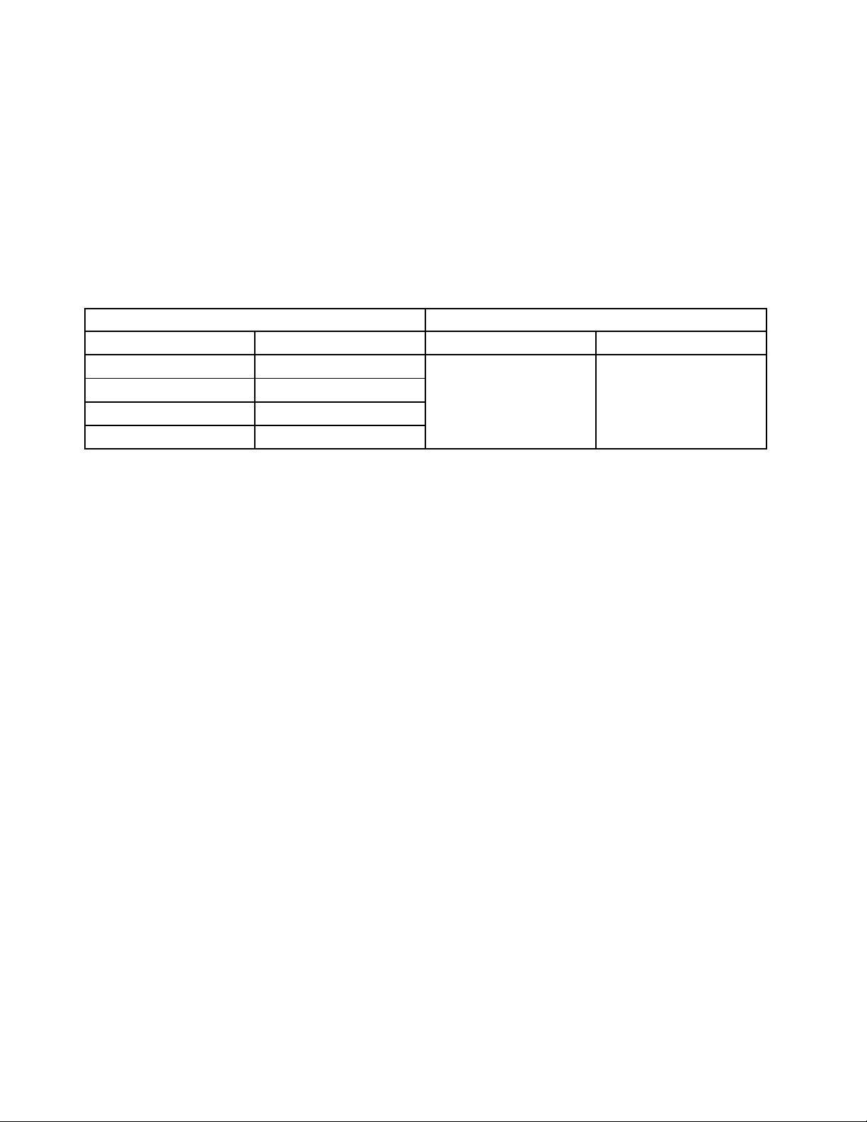
RoHScompliantThinkCentrepartshaveuniqueFRUpartnumbers.BeforeorafterJune2006,failedRoHS
compliantpartsmustalwaysbereplacedusingRoHScompliantFRUs,soonlytheFRUsidentiedas
compliantinthesystemhardwaremaintenancemanualmanordirectsubstitutionsforthoseFRUscanbe
used.
ProductsmarketedbeforeJune2006ProductsmarketedafterJune2006
Currentororiginalpart
Non-RoHSCanbeNon-RoHS
Non-RoHSCanbeRoHS
Non-RoHSCansubstitutetoRoHS
RoHSMustbeRoHS
ReplacementFRU
Currentororiginalpart
MustbeRoHSMustbeRoHS
ReplacementFRU
Note:AdirectsubstitutionisapartwithadifferentFRUpartnumberthatisautomaticallyshippedbythe
distributioncenteratthetimeoforder.
2HardwareMaintenanceManual
Page 9

Chapter2.Safetyinformation
Thischaptercontainsthesafetyinformationthatyouneedtobefamiliarwithbeforeservicingacomputer.
Generalsafety
Followtheserulestoensuregeneralsafety:
•Observegoodhousekeepingintheareaofthemachinesduringandaftermaintenance.
•Whenliftinganyheavyobject:
1.Ensureyoucanstandsafelywithoutslipping.
2.Distributetheweightoftheobjectequallybetweenyourfeet.
3.Useaslowliftingforce.Nevermovesuddenlyortwistwhenyouattempttolift.
4.Liftbystandingorbypushingupwithyourlegmuscles;thisactionremovesthestrainfromthe
musclesinyourback.Donotattempttoliftanyobjectsthatweighmorethan16kg(35lb)orobjects
thatyouthinkaretooheavyforyou.
•Donotperformanyactionthatcauseshazardstothecustomer,orthatmakestheequipmentunsafe.
•Beforeyoustartthemachine,ensurethatotherservicerepresentativesandthecustomer'spersonnelare
notinahazardousposition.
•Placeremovedcoversandotherpartsinasafeplace,awayfromallpersonnel,whileyouareservicing
themachine.
•Keepyourtoolcaseawayfromwalkareassothatotherpeoplewillnottripoverit.
•Donotwearlooseclothingthatcanbetrappedinthemovingpartsofamachine.Ensurethatyoursleeves
arefastenedorrolledupaboveyourelbows.Ifyourhairislong,fastenit.
•Inserttheendsofyournecktieorscarfinsideclothingorfastenitwithanonconductiveclip,approximately
8centimeters(3inches)fromtheend.
•Donotwearjewelry,chains,metal-frameeyeglasses,ormetalfastenersforyourclothing.Remember:
Metalobjectsaregoodelectricalconductors.
•Wearsafetyglasseswhenyouare:hammering,drilling,soldering,cuttingwire,attachingsprings,using
solvents,orworkinginanyotherconditionsthatmightbehazardoustoyoureyes.
•Afterservice,reinstallallsafetyshields,guards,labels,andgroundwires.Replaceanysafetydevice
thatiswornordefective.
•Reinstallallcoverscorrectlybeforereturningthemachinetothecustomer.
Electricalsafety
CAUTION:
Electricalcurrentfrompower,telephone,andcommunicationcablescanbehazardous.T oavoid
personalinjuryorequipmentdamage,disconnecttheattachedpowercords,telecommunication
systems,networks,andmodemsbeforeyouopentheserver/workstationcovers,unlessinstructed
otherwiseintheinstallationandcongurationprocedures.
Observethefollowingruleswhenworkingonelectricalequipment.
©CopyrightLenovo2009,2010
3
Page 10

Important:Useonlyapprovedtoolsandtestequipment.Somehandtoolshavehandlescoveredwithasoft
materialthatdoesnotinsulateyouwhenworkingwithliveelectricalcurrents.Manycustomershave,near
theirequipment,rubberoormatsthatcontainsmallconductiveberstodecreaseelectrostaticdischarges.
Donotusethistypeofmattoprotectyourselffromanelectricshock.
•Findtheroomemergencypower-off(EPO)switch,disconnectingswitch,orelectricaloutlet.Ifanelectrical
accidentoccurs,youcanthenoperatetheswitchorunplugthepowercordquickly.
•Donotworkaloneunderhazardousconditionsornearequipmentthathashazardousvoltages.
•Disconnectallpowerbefore:
–Performingamechanicalinspection
–Workingnearpowersupplies
–RemovingorinstallingFieldReplaceableUnits(FRU)
•Beforeyoustarttoworkonthemachine,unplugthepowercord.Ifyoucannotunplugit,askthecustomer
topower-offthewallboxthatsuppliespowertothemachineandtolockthewallboxintheoffposition.
•Ifyouneedtoworkonamachinethathasexposedelectricalcircuits,observethefollowingprecautions:
–Ensurethatanotherperson,familiarwiththepower-offcontrols,isnearyou.Remember:Another
personmustbetheretoswitchoffthepower,ifnecessary.
–Useonlyonehandwhenworkingwithpowered-onelectricalequipment;keeptheotherhandinyour
pocketorbehindyourback.Remember:Theremustbeacompletecircuittocauseanelectricshock.
Byobservingtheaboverule,youmaypreventacurrentfrompassingthroughyourbody.
–Whenusingatester,setthecontrolscorrectlyandusetheapprovedprobeleadsandaccessoriesfor
thattester.
–Standonsuitablerubbermats(obtainedlocally,ifnecessary)toinsulateyoufromgroundssuchas
metaloorstripsandmachineframes.
Observethespecialsafetyprecautionswhenyouworkwithveryhighvoltages;theseinstructionsarein
thesafetysectionsofmaintenanceinformation.Useextremecarewhenmeasuringhighvoltages.
•Regularlyinspectandmaintainyourelectricalhandtoolsforsafeoperationalcondition.
•Donotusewornorbrokentoolsandtesters.
•Neverassumethatpowerhasbeendisconnectedfromacircuit.First,checkthatithasbeenpowered-off.
•Alwayslookcarefullyforpossiblehazardsinyourworkarea.Examplesofthesehazardsaremoistoors,
nongroundedpowerextensioncables,powersurges,andmissingsafetygrounds.
•Donottouchliveelectricalcircuitswiththereectivesurfaceofaplasticdentalmirror.Thesurfaceis
conductive;suchtouchingcancausepersonalinjuryandmachinedamage.
•Donotservicethefollowingpartswiththepoweronwhentheyareremovedfromtheirnormaloperating
placesinamachine:
–Powersupplyunits
–Pumps
–Blowersandfans
–Motorgenerators
andsimilarunits.(Thispracticeensurescorrectgroundingoftheunits.)
•Ifanelectricalaccidentoccurs:
–Usecaution;donotbecomeavictimyourself.
–Switchoffpower.
–Sendanotherpersontogetmedicalaid.
4HardwareMaintenanceManual
Page 11

Voltage-selectionswitch
Somecomputersareequippedwithavoltage-selectionswitchlocatednearthepower-cordconnection
pointonthecomputer.Ifyourcomputerhasavoltage-selectionswitch,ensurethatyousettheswitchto
matchthevoltageavailableatyourelectricaloutlet.Settingthevoltage-selectionswitchincorrectlycan
causepermanentdamagetothecomputer.
Ifyourcomputerdoesnothaveavoltage-selectionswitch,yourcomputerisdesignedtooperateonlyatthe
voltageprovidedinthecountryorregionwherethecomputerwasoriginallypurchased.
Ifyourelocateyourcomputertoanothercountry,beawareofthefollowing:
•Ifyourcomputerdoesnothaveavoltage-selectionswitch,donotconnectthecomputertoanelectrical
outletuntilyouhaveveriedthatthevoltageprovidedisthesameasitwasinthecountryorregion
wherethecomputerwasoriginallypurchased.
•Ifyourcomputerhasavoltage-selectionswitch,donotconnectthecomputertoanelectricaloutletuntil
youhaveveriedthatthevoltage-selectionswitchissettomatchthevoltageprovidedinthatcountry
orregion.
Ifyouarenotsureofthevoltageprovidedatyourelectricaloutlet,contactyourlocalelectriccompanyor
refertoofcialWebsitesorotherliteraturefortravelerstothecountryorregionwhereyouarelocated.
Safetyinspectionguide
Theintentofthisinspectionguideistoassistyouinidentifyingpotentiallyunsafeconditionsonthese
products.Eachmachine,asitwasdesignedandbuilt,hadrequiredsafetyitemsinstalledtoprotectusers
andservicepersonnelfrominjury.Thisguideaddressesonlythoseitems.However,goodjudgmentshould
beusedtoidentifypotentialsafetyhazardsduetoattachmentoffeaturesoroptionsnotcoveredbythis
inspectionguide.
Ifanyunsafeconditionsarepresent,youmustdeterminehowserioustheapparenthazardcouldbeand
whetheryoucancontinuewithoutrstcorrectingtheproblem.
Considertheseconditionsandthesafetyhazardstheypresent:
•Electricalhazards,especiallyprimarypower(primaryvoltageontheframecancauseseriousorfatal
electricalshock).
•Explosivehazards,suchasadamagedCRTfaceorbulgingcapacitor
•Mechanicalhazards,suchaslooseormissinghardware
Theguideconsistsofaseriesofstepspresentedinachecklist.Beginthecheckswiththepoweroff,and
thepowercorddisconnected.
Checklist:
1.Checkexteriorcoversfordamage(loose,broken,orsharpedges).
2.Power-offthecomputer.Disconnectthepowercord.
3.Checkthepowercordfor:
a.Athird-wiregroundconnectoringoodcondition.Useametertomeasurethird-wireground
continuityfor0.1ohmorlessbetweentheexternalgroundpinandframeground.
b.Thepowercordshouldbetheappropriatetypeasspeciedinthepartslistings.
c.Insulationmustnotbefrayedorworn.
4.Removethecover.
Chapter2.Safetyinformation5
Page 12

5.Checkforanyobviousalterations.Usegoodjudgmentastothesafetyofanyalterations.
6.Checkinsidetheunitforanyobviousunsafeconditions,suchasmetallings,contamination,wateror
otherliquids,orsignsofreorsmokedamage.
7.Checkforworn,frayed,orpinchedcables.
8.Checkthatthepower-supplycoverfasteners(screwsorrivets)havenotbeenremovedortamperedwith.
Handlingelectrostaticdischarge-sensitivedevices
Anycomputerpartcontainingtransistorsorintegratedcircuits(ICs)shouldbeconsideredsensitiveto
electrostaticdischarge(ESD).ESDdamagecanoccurwhenthereisadifferenceinchargebetweenobjects.
ProtectagainstESDdamagebyequalizingthechargesothatthemachine,thepart,theworkmat,andthe
personhandlingthepartareallatthesamecharge.
1.Useproduct-specicESDprocedureswhentheyexceedtherequirementsnotedhere.
2.MakesurethattheESDprotectivedevicesyouusehavebeencertied(ISO9000)asfullyeffective.
WhenhandlingESD-sensitiveparts:
•Keepthepartsinprotectivepackagesuntiltheyareinsertedintotheproduct.
•Avoidcontactwithotherpeoplewhilehandlingthepart.
•Wearagroundedwriststrapagainstyourskintoeliminatestaticonyourbody.
•Preventthepartfromtouchingyourclothing.Mostclothingisinsulativeandretainsachargeevenwhen
youarewearingawriststrap.
•Usetheblacksideofagroundedworkmattoprovideastatic-freeworksurface.Thematisespecially
usefulwhenhandlingESD-sensitivedevices.
•Selectagroundingsystem,suchasthoselistedbelow,toprovideprotectionthatmeetsthespecic
servicerequirement.
Note:TheuseofagroundingsystemisdesirablebutnotrequiredtoprotectagainstESDdamage.
–AttachtheESDgroundcliptoanyframeground,groundbraid,orgreen-wireground.
–UseanESDcommongroundorreferencepointwhenworkingonadouble-insulatedor
battery-operatedsystem.Youcanusecoaxorconnector-outsideshellsonthesesystems.
–Usetheroundground-prongoftheacplugonac-operatedcomputers.
Groundingrequirements
Electricalgroundingofthecomputerisrequiredforoperatorsafetyandcorrectsystemfunction.Proper
groundingoftheelectricaloutletcanbeveriedbyacertiedelectrician.
Safetynotices(multi-lingualtranslations)
Thecautionanddangersafetynoticesinthissectionareprovidedinthefollowinglanguages:
•English
•Arabic
•Brazilian/Portuguese
•Chinese(simplied)
•Chinese(traditional)
•French
6HardwareMaintenanceManual
Page 13
•German
•Hebrew
•Italian
•Korean
•Spanish
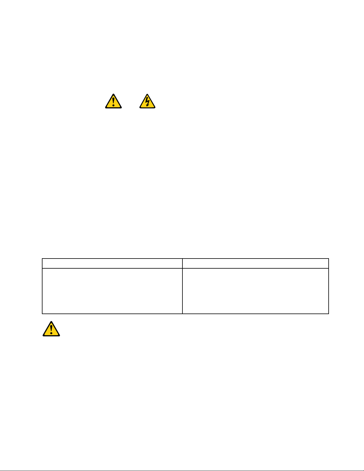
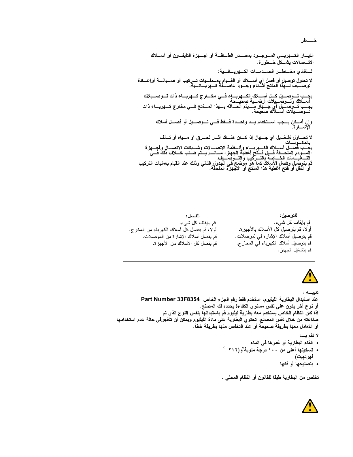
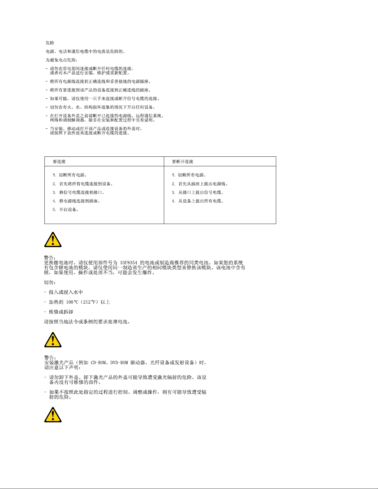
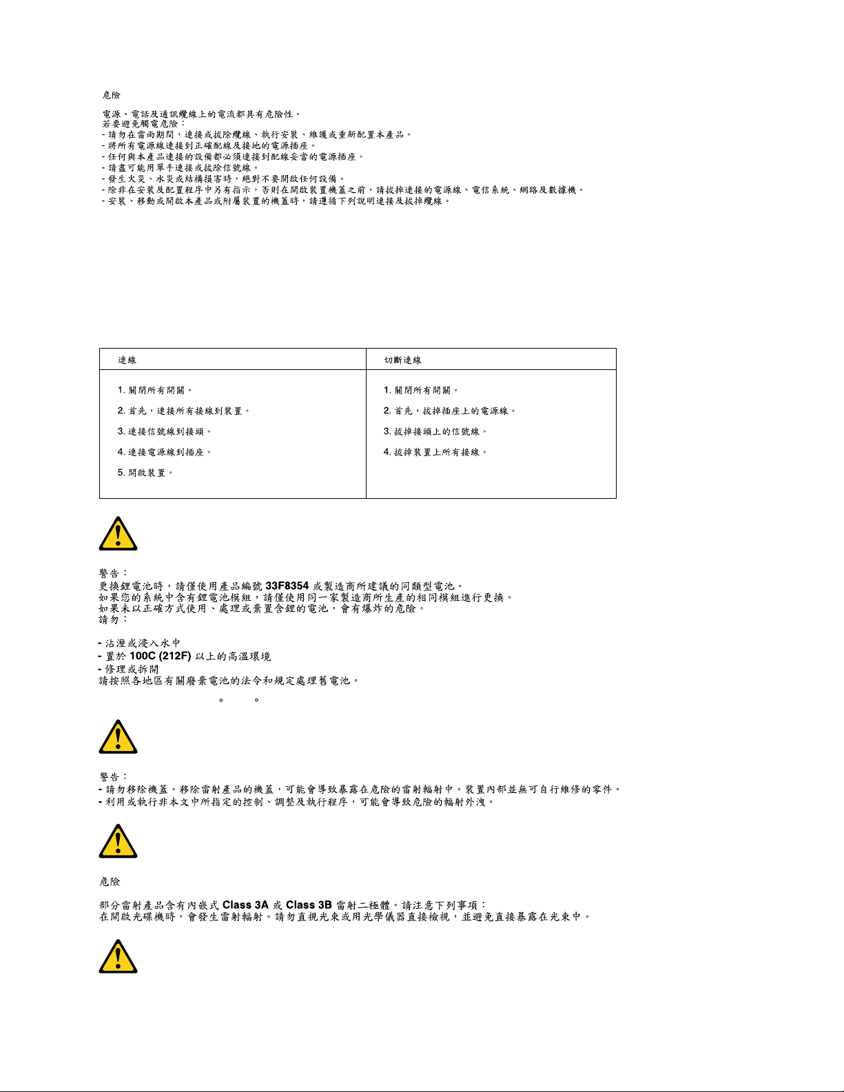
DANGER
Electricalcurrentfrompower,telephoneandcommunicationcablesishazardous.
Toavoidashockhazard:
•Donotconnectordisconnectanycablesorperforminstallation,maintenance,orreconguration
ofthisproductduringanelectricalstorm.
•Connectallpowercordstoaproperlywiredandgroundedelectricaloutlet.
•Connecttoproperlywiredoutletsanyequipmentthatwillbeattachedtothisproduct.
•Whenpossible,useonehandonlytoconnectordisconnectsignalcables.
•Neverturnonanyequipmentwhenthereisevidenceofre,water,orstructuraldamage.
•Disconnecttheattachedpowercords,telecommunicationssystems,networks,andmodems
beforeyouopenthedevicecovers,unlessinstructedotherwiseintheinstallationandconguration
procedures.
•Connectanddisconnectcablesasdescribedinthefollowingtableswheninstalling,moving,or
openingcoversonthisproductorattacheddevices.
ToConnectToDisconnect
1.TurneverythingOFF.
2.First,attachallcablestodevices.
3.Attachsignalcablestoconnectors.
4.Attachpowercordstooutlet.
5.TurndeviceON.
1.TurneverythingOFF.
2.First,removepowercordsfromoutlet.
3.Removesignalcablesfromconnectors.
4.Removeallcablesfromdevices.
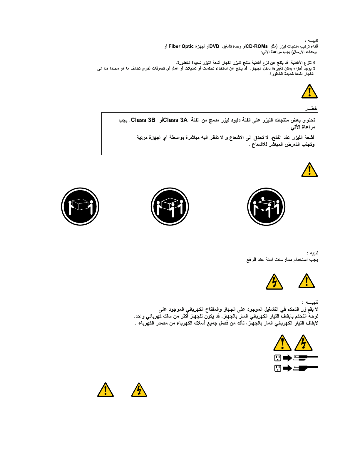
CAUTION:
Whenreplacingthelithiumbattery,useonlyPartNumber45C1566oranequivalenttypebattery
recommendedbythemanufacturer.Ifyoursystemhasamodulecontainingalithiumbattery,replace
itonlywiththesamemoduletypemadebythesamemanufacturer.Thebatterycontainslithiumand
canexplodeifnotproperlyused,handled,ordisposedof.Donot:
•Throworimmerseintowater
•Heattomorethan100°C(212°F)
•Repairordisassemble
Disposeofthebatteryasrequiredbylocalordinancesorregulations.
Chapter2.Safetyinformation7
Page 14
CAUTION:
1
2
Whenlaserproducts(suchasCD-ROMs,DVD-ROMdrives,beropticdevices,ortransmitters)are
installed,notethefollowing:
•Donotremovethecovers.Removingthecoversofthelaserproductcouldresultinexposureto
hazardouslaserradiation.Therearenoserviceablepartsinsidethedevice.
•Useofcontrolsoradjustmentsorperformanceofproceduresotherthanthosespeciedherein
mightresultinhazardousradiationexposure.
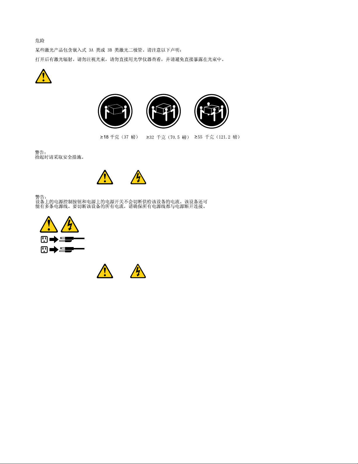
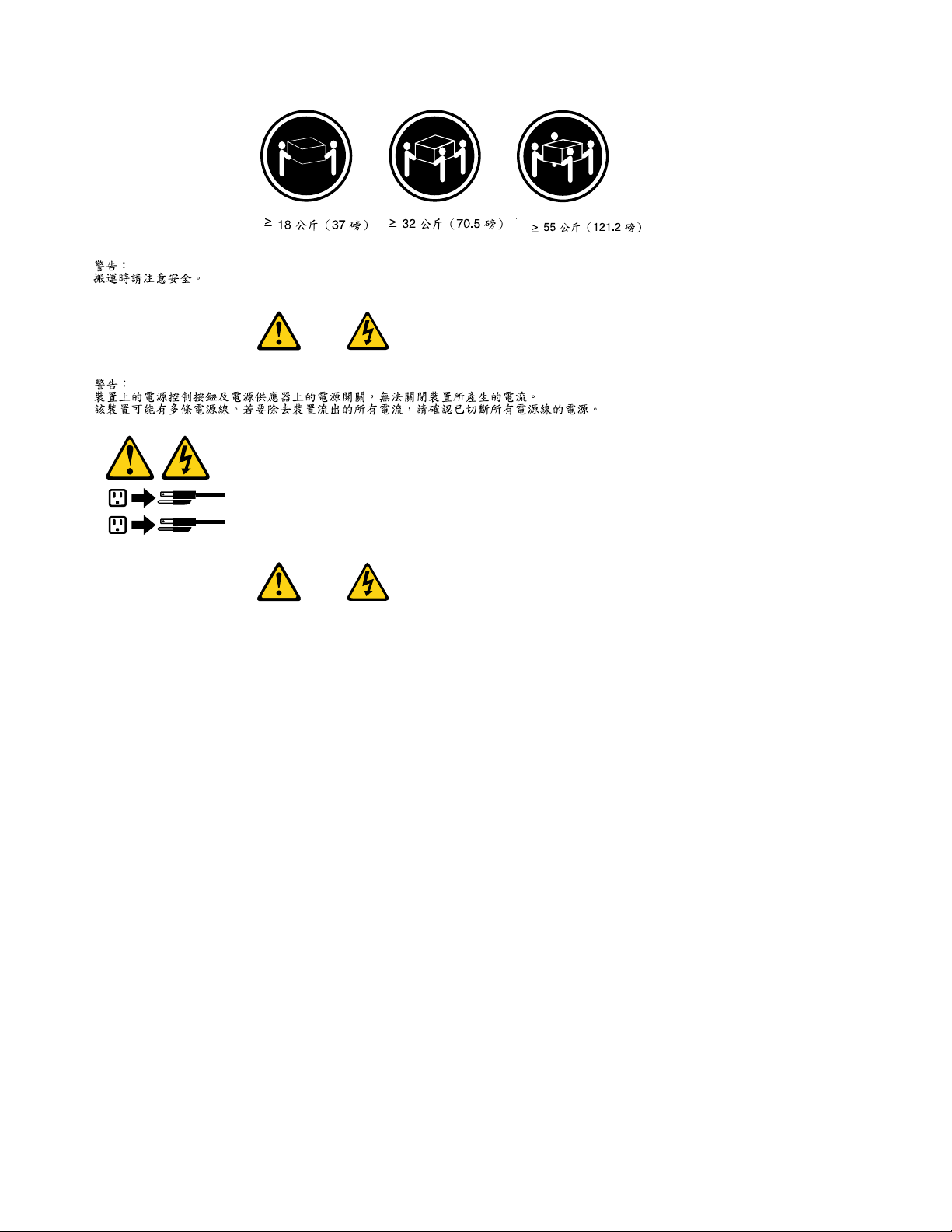
DANGER
SomelaserproductscontainanembeddedClass3AorClass3Blaserdiode.Notethefollowing:
Laserradiationwhenopen.Donotstareintothebeam,donotviewdirectlywithoptical
instruments,andavoiddirectexposuretothebeam.
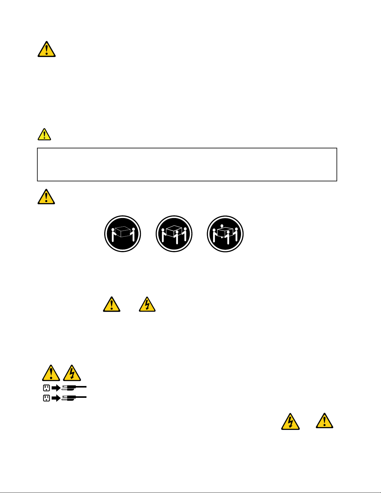
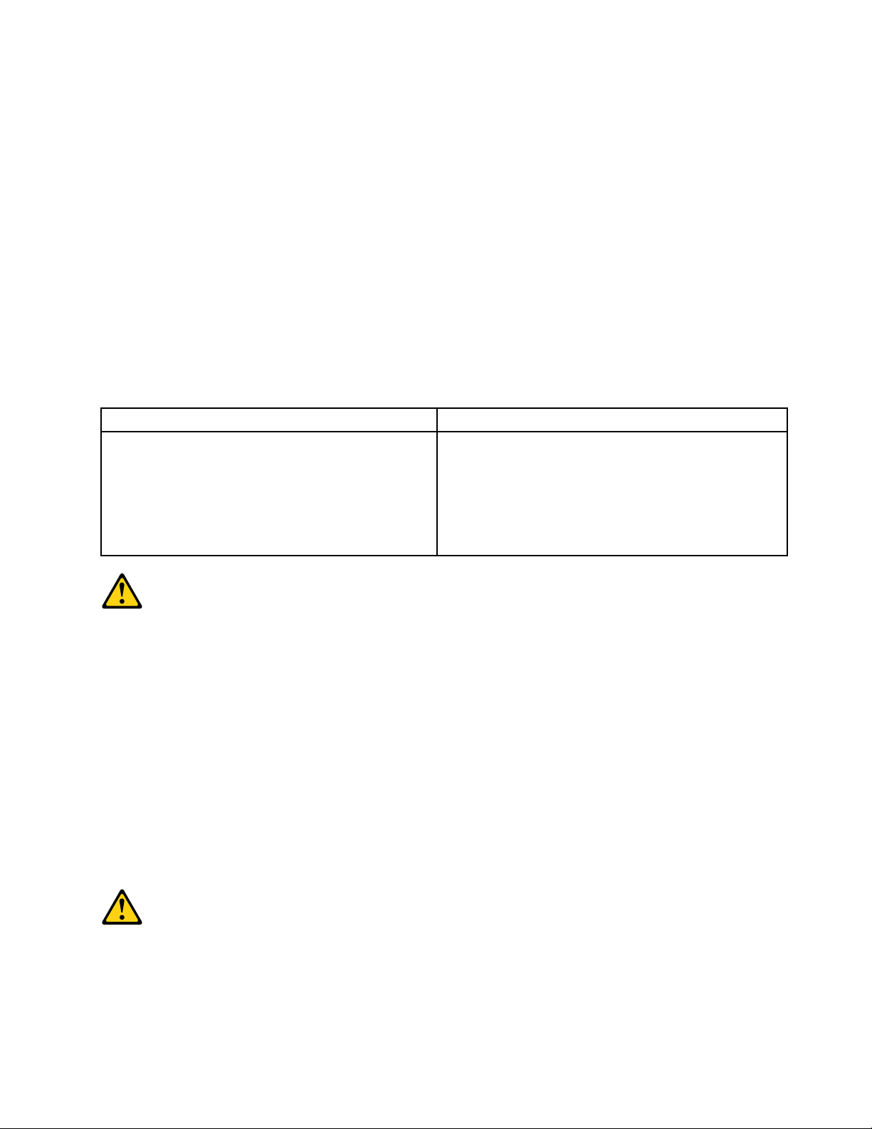
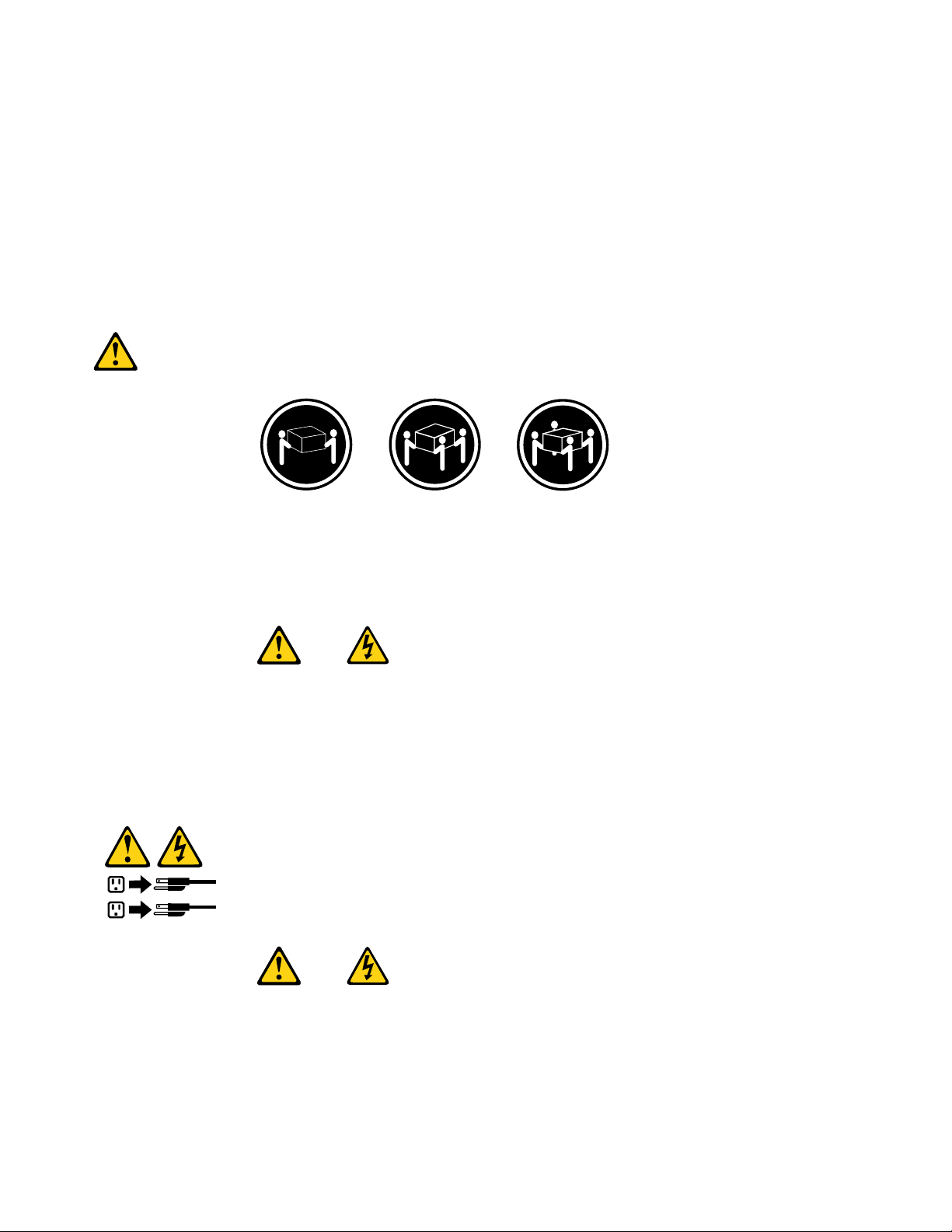
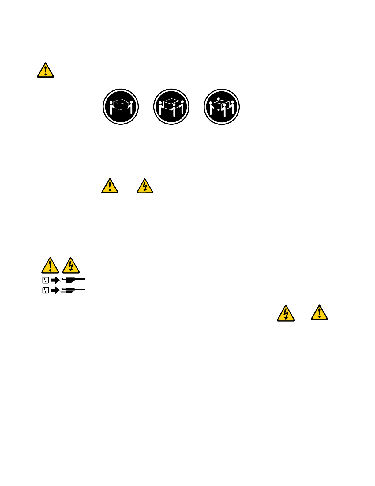
≥18kg(37lbs)≥32kg(70.5lbs)≥55kg(121.2lbs)
CAUTION:
Usesafepracticeswhenlifting.
CAUTION:
Thepowercontrolbuttononthedeviceandthepowerswitchonthepowersupplydonotturnoff
theelectricalcurrentsuppliedtothedevice.Thedevicealsomighthavemorethanonepower
cord.Toremoveallelectricalcurrentfromthedevice,ensurethatallpowercordsaredisconnected
fromthepowersource.
8HardwareMaintenanceManual
Page 15
Chapter2.Safetyinformation9
Page 16
≥18kg(37lbs)≥32kg(70.5lbs)≥55kg(121.2lbs)
1
2
PERIGO
10HardwareMaintenanceManual
Page 17
Acorrenteelétricaprovenientedecabosdealimentação,detelefoneedecomunicaçõeséperigosa.
Paraevitarriscodechoqueelétrico:
•Nãoconectenemdesconectenenhumcaboouexecuteinstalação,manutençãooureconguração
desteprodutoduranteumatempestadecomraios.
•Conectetodososcabosdealimentaçãoatomadaselétricascorretamenteinstaladaseaterradas.
•T odoequipamentoqueforconectadoaesteprodutodeveserconectadoatomadascorretamente
instaladas.
•Quandopossível,utilizeapenasumadasmãosparaconectaroudesconectarcabosdesinal.
•Nuncaliguenenhumequipamentoquandohouverevidênciadefogo,águaoudanosestruturais.
•Antesdeabrirtampasdedispositivos,desconectecabosdealimentação,sistemasdetelecomunicação,
redesemodemsconectados,amenosqueespecicadodemaneiradiferentenosprocedimentosde
instalaçãoeconguração.
•Conecteedesconecteoscabosconformedescritonatabelaapresentadaaseguiraoinstalar,moverou
abrirtampasdesteprodutooudedispositivosconectados.
ParaConectar:ParaDesconectar:
1.DESLIGUET udo.
2.Primeiramente,conectetodososcabosaos
dispositivos.
3.Conecteoscabosdesinalaosconectores.
4.Conecteoscabosdealimentaçãoàstomadas.
5.LIGUEosdispositivos.
1.DESLIGUET udo.
2.Primeiramente,removaoscabosdealimentaçãodas
tomadas.
3.Removaoscabosdesinaldosconectores.
4.Removatodososcabosdosdispositivos.
CUIDADO:
Aosubstituirabateriadelítio,utilizeapenasumabateriacomNúmerodePeça45C1566ouumtipo
debateriaequivalenterecomendadopeloSeoseusistemapossuiummódulocomumabateriade
lítio,substitua-oapenasporummódulodomesmotipoedomesmofabricante.Abateriacontémlítio
epodeexplodirsenãoforutilizada,manuseadaoudescartadademaneiracorreta.
Não:
•Jogueoucoloquenaágua
•Aqueçaamaisde100°C(212°F)
•Consertenemdesmonte
Descarteabateriaconformerequeridopelasleisouregulamentoslocais.
PRECAUCIÓN:
Quandoprodutosalaser(comounidadesdeCD-ROMs,unidadesdeDVD-ROM,dispositivosdebraótica
outransmissores)estivereminstalados,observeoseguinte:
Chapter2.Safetyinformation11
Page 18
•Nãoremovaastampas.Aremoçãodastampasdeumprodutoalaserpoderesultaremexposição
1
2
prejudicialàradiaçãodelaser.Nãoexistempeçasquepodemserconsertadasnointeriordodispositivo.
•Autilizaçãodecontrolesouajustesouaexecuçãodeprocedimentosdiferentesdosespecicadosaqui
poderesultaremexposiçãoprejudicialàradiação.
PERIGO
AlgunsprodutosalasercontêmdiododelaserintegradodaClasse3AoudaClasse3B.Observeoseguinte:
Radiaçãoalaserquandoaberto.Nãoolhediretamenteparaofeixeaolhonuoucominstrumentosópticose
eviteexposiçãodiretaaofeixe.
≥18kg(37lbs)≥32kg(70.5lbs)≥55kg(121.2lbs)
CUIDADO:
Utilizeprocedimentosdesegurançaparalevantarequipamentos.
CUIDADO:
Obotãodecontroledealimentaçãododispositivoeobotãoparaligar/desligardafontedealimentação
nãodesligamacorrenteelétricafornecidaaodispositivo.Odispositivotambémpodetermaisdeumcabo
dealimentação.Pararemovertodaacorrenteelétricadodispositivo,assegurequetodososcabosde
alimentaçãoestejamdesconectadosdafontedealimentação.
12HardwareMaintenanceManual
Page 19
Chapter2.Safetyinformation13
Page 20
1
2
14HardwareMaintenanceManual
Page 21
Chapter2.Safetyinformation15
Page 22
1
2
DANGER
Lecourantélectriqueprovenantdel'alimentation,dutéléphoneetdescâblesdetransmissionpeutprésenter
undanger.
Pourévitertoutrisquedechocélectrique:
•Nemanipulezaucuncâbleetn'effectuezaucuneopérationd'installation,d'entretienoudereconguration
deceproduitaucoursd'unorage.
•Brancheztouslescordonsd'alimentationsurunsocledeprisedecourantcorrectementcâbléetmisàla
terre.
•Branchezsurdessoclesdeprisedecourantcorrectementcâbléstoutéquipementconnectéàceproduit.
•Lorsquecelaestpossible,n'utilisezqu'uneseulemainpourconnecteroudéconnecterlescâbles
d'interface.
•Nemettezjamaisunéquipementsoustensionencasd'incendieoud'inondation,ouenprésencede
dommagesmatériels.
•Avantderetirerlescartersdel'unité,mettezcelle-cihorstensionetdéconnectezsescordons
d'alimentation,ainsiquelescâblesquilarelientauxréseaux,auxsystèmesdetélécommunicationetaux
modems(saufinstructioncontrairementionnéedanslesprocéduresd'installationetdeconguration).
•Lorsquevousinstallez,quevousdéplacez,ouquevousmanipulezleprésentproduitoudespériphériques
quiluisontraccordés,reportez-vousauxinstructionsci-dessouspourconnecteretdéconnecterles
différentscordons.
16HardwareMaintenanceManual
Page 23
ConnexionDéconnexion
1.MettezlesunitésHORSTENSION.
2.Commencezparbranchertouslescordonssurles
unités.
3.Branchezlescâblesd'interfacesurdesconnecteurs.
4.Branchezlescordonsd'alimentationsurdesprises.
5.MettezlesunitésSOUSTENSION.
1.MettezlesunitésHORSTENSION.
2.Débranchezlescordonsd'alimentationdesprises.
3.Débranchezlescâblesd'interfacedesconnecteurs.
4.Débrancheztouslescâblesdesunités.
ATTENTION:
Remplacerlapileaulithiumusagéeparunepilederéférenceidentiqueexclusivement,(référence
45C1566),ousuivrelesinstructionsdufabricantquiendénitleséquivalences.Sivotresystèmeest
dotéd'unmodulecontenantunepileaulithium,vousdevezleremplaceruniquementparunmodule
identique,produitparlemêmefabricant.Lapilecontientdulithiumetpeutexploserencasde
mauvaiseutilisation,demauvaisemanipulationoudemiseaurebutinappropriée.
Nepas:
•lajeteràl'eau,
•l'exposeràdestempératuressupérieuresà100°C,
•chercheràlaréparerouàladémonter.
Nepasmettrelapileàlapoubelle.Pourlamiseaurebut,sereporteràlaréglementationenvigueur.
ATTENTION:
Sidesproduitsàlaser(telsquedesunitésdeCD-ROM,deDVD-ROM,desunitésàbresoptiques,ou
desémetteurs)sontinstallés,prenezconnaissancedesinformationssuivantes:
•Neretirezpaslecarter.Enouvrantl'unitédeCD-ROMoudeDVD-ROM,vousvousexposezau
rayonnementdangereuxdulaser.Aucunepiècedel'unitén'estréparable.
•Pourévitertoutrisqued'expositionaurayonlaser,respectezlesconsignesderéglageet
d'utilisationdescommandes,ainsiquelesprocéduresdécritesdansleprésentmanuel.
DANGER
Certainsproduitsàlasercontiennentunediodeàlaserintégréedeclasse3Aou3B.Prenez
connaissancedesinformationssuivantes:
Rayonnementlaserlorsquelecarterestouvert.Eviteztouteexpositiondirecteaurayonlaser.Evitez
deregarderxementlefaisceauoudel'observeràl'aided'instrumentsoptiques.
Chapter2.Safetyinformation17
Page 24
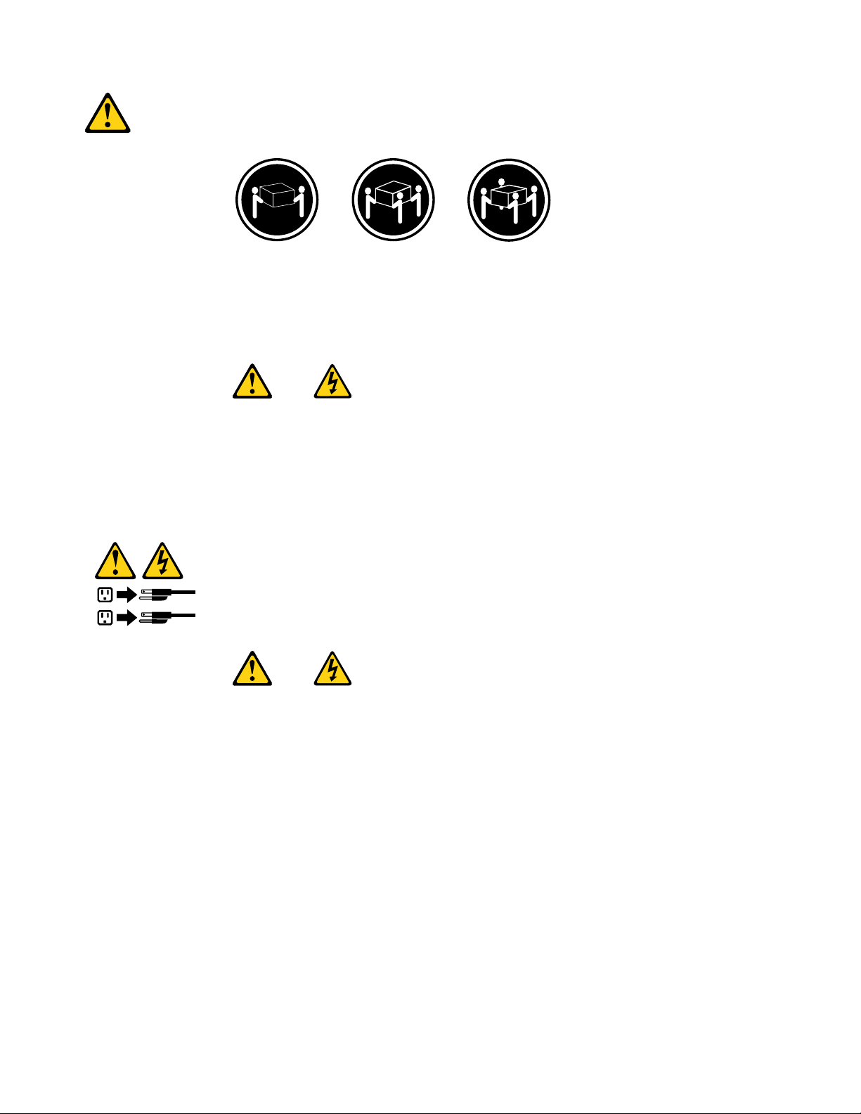
≥18kg(37lbs)≥32kg(70.5lbs)≥55kg(121.2lbs)
1
2
ATTENTION:
Soulevezlamachineavecprécaution.
ATTENTION:
L'interrupteurdecontrôled'alimentationdel'unitéetl'interrupteurdublocd'alimentationnecoupent
paslecourantélectriquealimentantl'unité.Enoutre,lesystèmepeutêtreéquipédeplusieurs
cordonsd'alimentation.Pourmettrel'unitéhorstension,vousdevezdéconnectertouslescordons
delasourced'alimentation.
VORSICHT
AnNetz-,Telefon-undDatenleitungenkönnengefährlicheSpannungenanliegen.
AusSicherheitsgründen:
•BeiGewitterandiesemGerätkeineKabelanschließenoderlösen.FernerkeineInstallations-,
Wartungs-oderRekongurationsarbeitendurchführen.
•GerätnuraneineSchutzkontaktsteckdosemitordnungsgemäßgeerdetemSchutzkontakt
anschließen.
•AlleangeschlossenenGeräteebenfallsanSchutzkontaktsteckdosenmitordnungsgemäß
geerdetemSchutzkontaktanschließen.
•DieSignalkabelnachMöglichkeiteinhändiganschließenoderlösen,umeinenStromschlagdurch
BerührenvonOberächenmitunterschiedlichemelektrischemPotenzialzuvermeiden.
•Geräteniemalseinschalten,wennHinweiseaufFeuer,WasseroderGebäudeschädenvorliegen.
18HardwareMaintenanceManual
Page 25

•DieVerbindungzudenangeschlossenenNetzkabeln,Telekommunikationssystemen,Netzwerken
undModemsistvordemÖffnendesGehäuseszuunterbrechen,sofernindenInstallations-und
KongurationsprozedurenkeineanderslautendenAnweisungenenthaltensind.
•ZumInstallieren,TransportierenundÖffnenderAbdeckungendesComputersoderder
angeschlossenenEinheitendieKabelgemäßderfolgendenTabelleanschließenundabziehen.
ZumAnschließenderKabelgehenSiewiefolgtvorZumAbziehenderKabelgehenSiewiefolgtvor
1.SchaltenSiealleEinheitenAUS.
2.SchließenSieerstalleKabelandieEinheitenan.
3.SchließenSiedieSignalkabelandieBuchsenan.
4.SchließenSiedieNetzkabelandieSteckdosean.
5.SchaltenSiedieEinheitEIN.
1.SchaltenSiealleEinheitenAUS.
2.ZiehenSiezuerstalleNetzkabelausden
Netzsteckdosen.
3.ZiehenSiedieSignalkabelausdenBuchsen.
4.ZiehenSiealleKabelvondenEinheitenab.
CAUTION:
EineverbrauchteLithiumbatterienurdurcheineBatteriemitderTeilenummer45C1566odereine
gleichwertige,vomHerstellerempfohleneBatterieersetzen.EnthältdasSystemeinModulmiteiner
Lithiumbatterie,diesesnurdurcheinModuldesselbenTypsundvondemselbenHerstellerersetzen.
DieBatterieenthältLithiumundkannbeiunsachgemäßerVerwendung,HandhabungoderEntsorgung
explodieren.
DieBatterienicht:
•mitWasserinBerührungbringen.
•über100Cerhitzen.
•reparierenoderzerlegen.
DieörtlichenBestimmungenfürdieEntsorgungvonSondermüllbeachten.
ACHTUNG:
BeiderInstallationvonLasergeräten(wieCD-ROM-Laufwerken,DVD-aufwerken,Einheitenmit
LichtwellenleitertechnikoderSendern)Folgendesbeachten:
•DieAbdeckungennichtentfernen.DurchEntfernenderAbdeckungendesLasergerätskönnen
gefährlicheLaserstrahlungenfreigesetztwerden.DasGerätenthältkeinezuwartendenTeile.
•WerdenSteuerelemente,EinstellungenoderDurchführungenvonProzedurenandersalshier
angegebenverwendet,kanngefährlicheLaserstrahlungauftreten.
VORSICHT
EinigeLasergeräteenthalteneineLaserdiodederKlasse3Aoder3B.BeachtenSieFolgendes:
Chapter2.Safetyinformation19
Page 26
LaserstrahlungbeigeöffneterVerkleidung.NichtindenStrahlblicken.KeineLupenoderSpiegel
1
2
verwenden.Strahlungsbereichmeiden.
≥18kg(37lbs)≥32kg(70.5lbs)≥55kg(121.2lbs)
ACHTUNG:
ArbeitsschutzrichtlinienbeimAnhebenderMaschinebeachten.
ACHTUNG:
MitdemNetzschalteranderEinheitundamNetzteilwirddieStromversorgungfürdieEinheit
nichtunterbrochen.DieEinheitkannauchmitmehrerenNetzkabelnausgestattetsein.Umdie
StromversorgungfürdieEinheitvollständigzuunterbrechen,müssenallezumGerätführenden
NetzkabelvomNetzgetrenntwerden.
20HardwareMaintenanceManual
Page 27
Chapter2.Safetyinformation21
Page 28
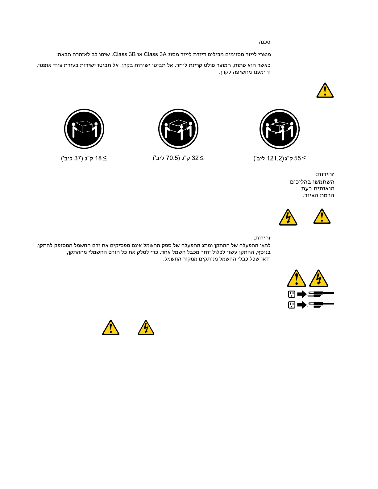
1
2
PERICOLO
Lacorrenteelettricaprovenientedaicavidialimentazione,deltelefonoedicomunicazionepuòessere
pericolosa.
Perevitareilrischiodiscosseelettriche:
•Noncollegareoscollegarequalsiasicavooppureeffettuarel'installazione,lamanutenzioneola
ricongurazionedelprodottoduranteuntemporale.
•Collegaretuttiilielettriciaunapresadialimentazionecorrettamentecablataedotatadimessaa
terra.
•Collegareallepreseelettricheappropriatetutteleapparecchiaturecheverrannoutilizzateper
questoprodotto.
22HardwareMaintenanceManual
Page 29
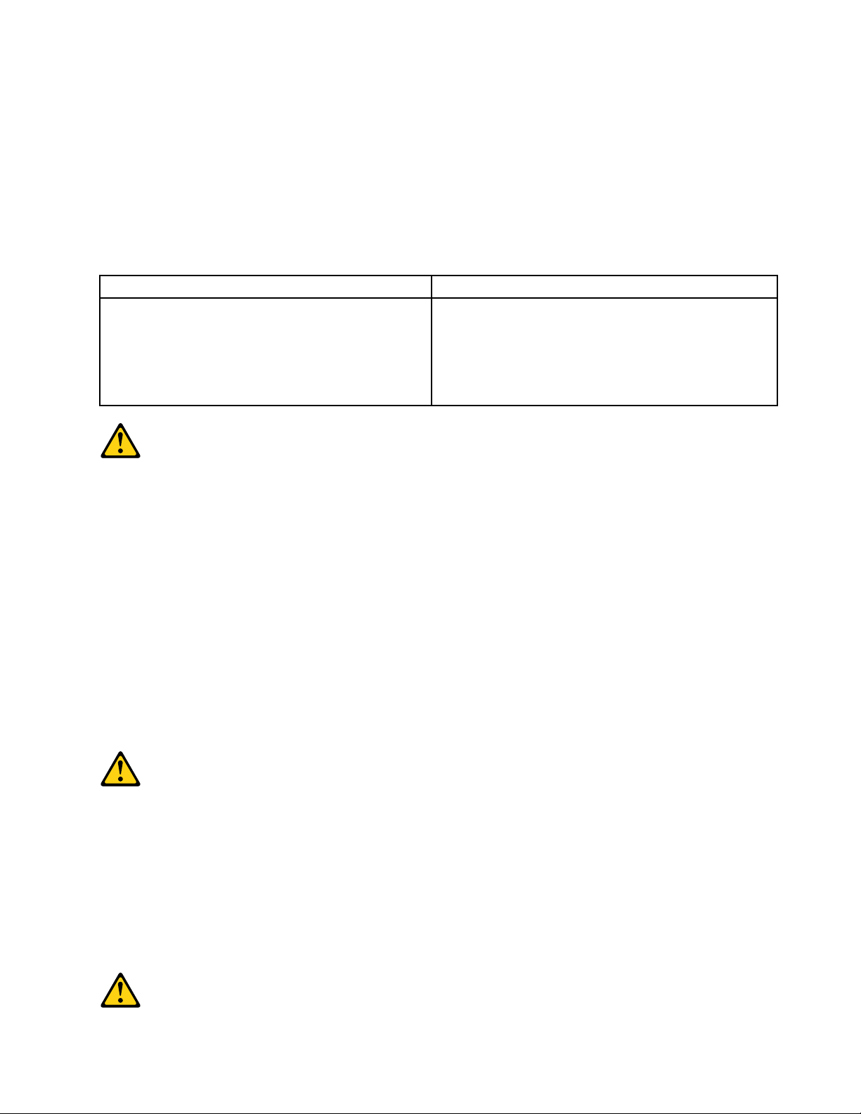
•Sepossibile,utilizzaresolounamanopercollegareoscollegareicavidisegnale.
•Nonaccendereassolutamenteapparecchiatureinpresenzadiincendi,perdited'acquaodanno
strutturale.
•Scollegareicavidialimentazione,isistemiditelecomunicazione,leretieilmodemprimadi
aprireicoperchideldispositivo,salvoistruzionicontrarierelativealleprocedurediinstallazionee
congurazione.
•Collegareescollegareicavicomedescrittonellaseguentetabellaquandovengonoeffettuate
operazionidiinstallazione,spostamentooaperturadeicoperchidiquestoprodottoodelleunità
collegate.
PercollegarsiPerscollegarsi
1.SPEGNEREleapparecchiature.
2.Innanzitutto,collegaretuttiicavialleunità.
3.Collegareicavidisegnaleaiconnettori.
4.Collegareicavidialimentazioneallapresa.
5.Accenderel'unità.
1.SPEGNEREleapparecchiature.
2.Innanzitutto,rimuovereicavidialimentazionedalla
presa.
3.Rimuovereicavidisegnaledaiconnettori.
4.Rimuoveretuttiicavidalleunità.
ATTENZIONE:
Quandosisostituiscelabatteriaallitio,utilizzaresoloilNumeroparte45C1566ountipodibatteria
equivalenteconsigliatodalproduttore.Sesulsistemaèpresenteunmodulochecontieneunabatteria
allitio,sostituirlosoloconuntipodimodulodellostessotipodellastessacasadiproduzione.La
batteriacontienelitioepuòesplodereseusata,maneggiataosmaltitainmodononcorretto.
Non:
•Gettareoimmergerelabatterianell'acqua
•Riscaldarlaadunatemperaturasuperioreai100gradiC(212gradiF)
•Smontarla,ricaricarlaotentarediripararla
Lebatterieusatevannosmaltiteinaccordoallanormativainvigore(DPR915/82esuccessive
disposizioniedisposizionilocali).
ATTENZIONE:
Quandovengonoinstallatiprodottilaser(qualiCD-ROM,unitàDVD-ROM,unitàabreotticheo
trasmittenti),tenerpresentequantosegue:
•Nonrimuovereglisportelli.L'aperturadiun'unitàlaserpuòdeterminarel'esposizionearadiazioni
laserpericolose.All'internodell'unitànonvisonopartisucuieffettuarel'assistenzatecnica.
•L'utilizzodicontrolli,regolazioniol'esecuzionediprocedurenondescrittinelpresentemanuale
possonoprovocarel'esposizionearadiazionipericolose.
Chapter2.Safetyinformation23
Page 30
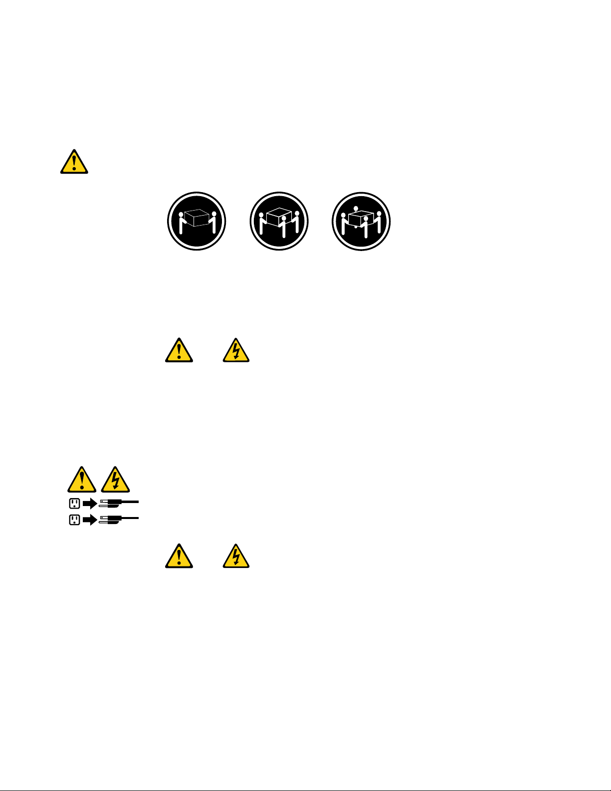
PERICOLO
1
2
AlcuneunitàlasercontengonoundiodolaserdiClasse3AoClasse3B.T enerpresentequantosegue:
Aprendol'unitàvengonoemesseradiazionilaser.Nonssareilfascio,nonguardarlodirettamente
construmentiotticiedevitarel'esposizionealfascio.
≥18kg(37lbs)≥32kg(70.5lbs)≥55kg(121.2lbs)
ATTENZIONE:
Prestareattenzionenelsollevarel'apparecchiatura.
ATTENZIONE:
Ilpulsantedicontrollodell'alimentazionepresentesull'unitàel'interruttoredell'alimentatorenon
disattivanol'alimentazionecorrentefornitaall'unità.E'possibilechel'unitàdispongadipiùcavidi
alimentazione.Perdisattivarel'alimentazionedall'unità,accertarsichetuttiicavidialimentazione
sianoscollegatidallafontedialimentazione.
24HardwareMaintenanceManual
Page 31
Chapter2.Safetyinformation25
Page 32
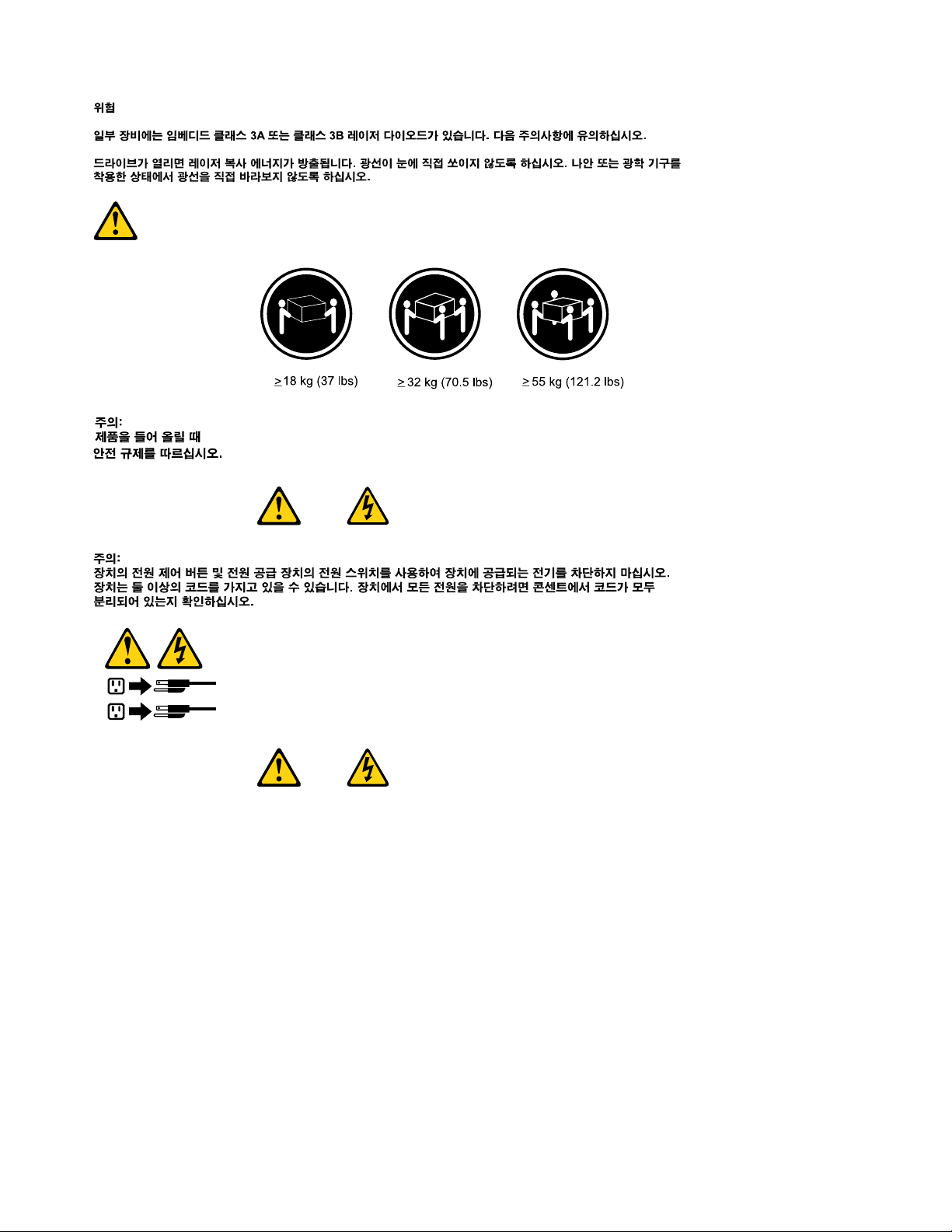
1
2
PELIGRO
Lacorrienteeléctricaprocedentedecablesdealimentación,teléfonosycablesdecomunicaciónpuede
serpeligrosa.
Paraevitarelriesgodedescargaeléctrica:
•Noconectenidesconecteloscablesnirealiceningunatareadeinstalación,mantenimientoo
reconguracióndeesteproductoduranteunatormentaeléctrica.
•Conectetodosloscablesdealimentaciónatomasdecorrientedebidamentecableadasy
conectadasatierra.
•Cualquierequipoqueseconecteaesteproductotambiéndebeconectarseatomasdecorriente
debidamentecableadas.
•Siemprequeseaposible,utiliceunasolamanoparaconectarodesconectarloscablesdeseñal.
•Noenciendanuncaunequipocuandohayseñalesdefuego,aguaodañosestructurales.
26HardwareMaintenanceManual
Page 33
•Desconecteloscablesdealimentación,lossistemasdetelecomunicaciones,lasredesylos
módemsconectadosantesdeabrirlascubiertasdelosdispositivos,amenosqueseindiquelo
contrarioenlosprocedimientosdeinstalaciónyconguración.
•Conecteydesconecteloscables,comosedescribeenlatablasiguiente,cuandoinstale,muevao
abralascubiertasdeesteproductoodelosdispositivosconectados.
ParaconectarParadesconectar
1.APÁGUELOtodo.
2.Enprimerlugar,conectetodosloscablesalos
dispositivos.
3.Conecteloscablesdeseñalalosconectores.
4.Enchufeloscablesdealimentaciónalastomasde
corriente.
5.Enciendaeldispositivo.
1.APÁGUELOtodo.
2.Enprimerlugar,desenchufeloscablesdealimentación
delastomasdecorriente.
3.Desconecteloscablesdeseñaldelosconectores.
4.Desconectetodosloscablesdelosdispositivos.
PRECAUCIÓN:
Cuandosustituyaunabateríadelitio,utilicesolamenteunabateríanúmerodepieza45C1566uotra
detipoequivalenterecomendadaporelfabricante.Sisusistemadisponedeunmóduloquecontiene
unabateríadelitio,reemplácelosóloconelmismotipodemódulo,delmismofabricante.Labatería
contienelitioypuedeexplotarsinoseutiliza,manipulaodesechacorrectamente.
Nodebe:
•Arrojarlaalaguaosumergirlaenella
•Exponerlaatemperaturassuperioresa100°C(212°F)
•Repararlaodesmontarla
Deshágasedelabateríasegúnespeciquenlasleyesonormaslocales.
PRECAUCIÓN:
Cuandohayaproductosláser(comounidadesdeCD-ROM,unidadesdeDVD,dispositivosdebra
ópticaotransmisores)instalados,tengaencuentalosiguiente:
•Noquitelascubiertas.Siquitalascubiertasdelproductoláser,podríaquedarexpuestoaradiación
láserpeligrosa.Dentrodeldispositivonoexisteningunapiezaquerequieraserviciotécnico.
•Siusacontrolesoajustesorealizaprocedimientosquenoseanlosespecicadosaquí,podría
exponersearadiacionespeligrosas.
PELIGRO
Chapter2.Safetyinformation27
Page 34
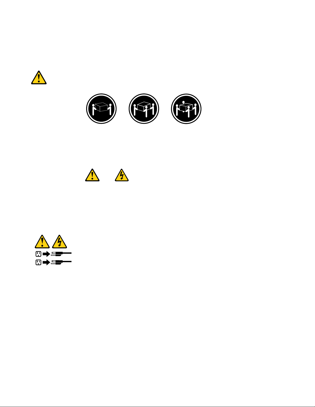
Algunosproductoslásertienenincorporadoundiodoláserdeclase3Aoclase3B.Tengaencuentalo
1
2
siguiente:
Cuandoseabre,quedaexpuestoaradiaciónláser.Nomiredirectamentealrayoláser,nisiquieracon
instrumentosópticos,yeviteexponersedirectamentealrayoláser.
≥18kg(37lbs)≥32kg(70.5lbs)≥55kg(121.2lbs)
PRECAUCIÓN:
Adopteprocedimientossegurosallevantarelequipo.
PRECAUCIÓN:
Elbotóndecontroldealimentacióndeldispositivoyelinterruptordealimentacióndelafuentede
alimentaciónnodesconectanlacorrienteeléctricasuministradaaldispositivo.Además,eldispositivo
podríatenermásdeuncabledealimentación.Parasuprimirtodalacorrienteeléctricadeldispositivo,
asegúresedequetodosloscablesdealimentaciónesténdesconectadosdelatomadecorriente.
28HardwareMaintenanceManual
Page 35

Chapter3.Generalinformation
Thischapterprovidesgeneralinformationthatyoucanusetoaccessusefulresourcesrelatingtoyour
computingneeds.
OnlineBooksfolder
TheOnlineBooksfolderpreinstalledonyourcomputercontainstheThinkCentreUserGuide,whichprovides
informationaboutyourcomputertohelpyousetup,use,andmaintainyourcomputer.Itrequiresno
Internetaccesstoviewthepublication.
Toviewthepublications,clickStart®AllPrograms®OnlineBooks®OnlineBooks,thendouble-click
theappropriatepublicationforyourcomputer.ThepublicationsarealsoavailableontheLenovoSupport
Websiteat:http://www.lenovo.com/support
Notes:
1.ThepublicationsareinPortableDocumentFormat(PDF).T oviewthepublications,youneedtohave
theAdobeReaderprogrampreinstalledonyourcomputer.IftheAdobeReaderprogramhasnotbeen
installedonyourcomputer,amessagewillappearwhenyouattempttoviewthePDFleandyouwillbe
guidedthroughtheAdobeReaderprograminstallation.
2.ThepublicationsareavailableinotherlanguagesontheLenovoSupportWebsite
at:http://www.lenovo.com/support
3.IfyouwanttoinstalladifferentlanguageversionoftheAdobeReaderprogramratherthantheversion
preinstalledonyourcomputer,downloadthelanguageversionyouwantfromtheAdobeWebsite
at:http://www.adobe.com
LenovoThinkVantageTools
TheLenovoThinkVantage®Toolsprogramguidesyoutoahostofinformationsourcesandprovideseasy
accesstovarioustoolstohelpyouworkmoreeasilyandsecurely.
Note:TheLenovoThinkVantageT oolsprogramisonlyavailableoncomputerspreinstalledwiththe
Microsoft®Windows®7operatingsystemfromLenovo.
ToaccesstheLenovoThinkVantageToolsprogram,clickStart®AllPrograms®LenovoThinkVantage
Tools.
ThinkVantageProductivityCenter
TheThinkVantageProductivityCenterprogramcontainsinformationsourcesandtoolsdesignedtomake
computingeasyandsecure.Itprovideseasyaccesstovarioustechnologies,suchas:
•PasswordManager
•PowerManager
•ProductRecovery
•RescueandRecovery®
•SystemUpdate
Note:TheThinkVantageProductivityCenterprogramisonlyavailableoncomputerspreinstalledwiththe
MicrosoftWindowsVista®operatingsystemortheMicrosoftWindowsXPoperatingsystemfromLenovo.
©CopyrightLenovo2009,2010
29
Page 36

ToaccesstheThinkVantageProductivityCenterprogram,clickStart®AllPrograms®ThinkVantage
®ProductivityCenter.
LenovoWelcome
TheLenovoWelcomeprogramintroducessomeinnovativebuilt-infeaturesofLenovotoyouandguidesyou
throughsomeimportantsetuptaskstohelpyoumakethemostofyourcomputer.
Note:TheLenovoWelcomeprogramisonlyavailableoncomputerspreinstalledwithWindows7or
WindowsVistafromLenovo.
AccessHelp
TheAccessHelpinformationsystemprovidesinformationaboutgettingstarted,doingbasictasks,
customizingsettingsforyourpersonalpreference,protectingdata,expandingandupgrading,and
troubleshooting.
•T oopentheAccessHelpinformationsystemonWindows7,clickStart®HelpandSupport®Lenovo
AccessHelp.
•T oopentheAccessHelpinformationsystemonWindowsVistaorWindowsXP ,clickStart®All
Programs®ThinkVantage®AccessHelp.
AfteryouhaveopenedtheAccessHelpinformationsystem,usetheleftpaneltomakeaselectionfromthe
ContentstabortheIndextab,orusetheSearchtabtondaparticularwordorphrase.
Additionalinformationresources
IfyouhaveInternetaccess,themostup-to-dateinformationforyourcomputerisavailable
at:http://www.lenovo.com/support
Youcanndthefollowinginformation:
•CustomerReplaceableUnit(CRU)installationorreplacementinstructions
•Downloadsanddrivers
•Partsinformation
•Publications
•T roubleshootinginformation
•Linkstootherusefulsourcesofinformation
Specications
Thissectionliststhephysicalspecicationsforyourcomputer.
30HardwareMaintenanceManual
Page 37

Dimensions
Width:286mm(11.26inches)
Height:82.5mm(3.25inches)
Depth:235.5mm(9.27inches)
Weight
Maximumcongurationasshipped:4.18kg(9.22lbs)
Environment
•Airtemperature:
Operating:10°to35°C(50°to95°F)
Non-operating:-40°to60°C(-40°to140°F)(withpackage)
Non-operating:-10°to60°C(14°to140°F)(withoutpackage)
•Humidity:
Operating:20%to80%(10%perhour,noncondensing)
Non-operating:20%to90%(10%perhour,noncondensing)
•Maximumaltitude:
Operating:-50to10000ft(-15.2to3048m)
Non-operating:-50to35000ft(-15.2to10668m)
Electricalinput
•Inputvoltage:
–Lowrange:
Minimum:100Vac
Maximum:127Vac
Inputfrequencyrange:50to60Hz
–Highrange:
Minimum:200Vac
Maximum:240Vac
Inputfrequencyrange:50to60Hz
Chapter3.Generalinformation31
Page 38

32HardwareMaintenanceManual
Page 39

Chapter4.Generalcheckout
Attention
Thedrivesinthecomputeryouareservicingmighthavebeenrearrangedorthedrivestartupsequencemight
hasbeenchanged.Beextremelycarefulduringwriteoperationssuchascopying,saving,orformatting.
Dataorprogramscanbeoverwrittenifyouselectanincorrectdrive.
Generalerrormessagesappearifaproblemorconictisfoundbyanapplicationprogram,theoperating
system,orboth.Fortheexplanationofthesemessages,refertotheinformationsuppliedwiththatsoftware
package.
BeforereplacinganyaFRU,makesurethatthelatestlevelofBasicInputOutputSystem(BIOS)isinstalled
onyourcomputer.Adown-levelBIOSmightcausefalseerrorsandunnecessaryreplacementofthesystem
board.FormoreinformationonhowtodetermineandobtainthelatestlevelBIOS,see“BIOSlevels”
onpage99
Usethefollowingproceduretohelpyoudeterminethecauseofaproblem:
1.T urnoffallattachedexternaldevicesandthecomputer.
2.Checkallcablesandpowercords.
3.Setalldisplaycontrolstothemiddleposition.
4.T urnonallattachedexternaldevicesandthecomputer.
•Lookforthedisplayederrorcodes
•Listenforthebeepcodes
•Lookforreadableinstructionsoramainmenuonthedisplay.
Ifyoudonotreceivethecorrectresponse,proceedtostep5onpage33
Ifyoudoreceivethecorrectresponse,runthediagnostics.See“Runningthediagnosticprogram
fromadiagnosticdisc”onpage38.
5.Checkthefollowingconditionsandfollowtheinstructions:
.
.
•Ifyouhearbeepcodesduringpower-onself-test(POST),goto“Beepsymptoms”onpage61
•IfthecomputerdisplaysaPOSTerror,goto“POSTerrorcodes”onpage61.
•Ifthecomputerhangsandnoerrorisdisplayed,goto“Powerproblems”onpage33.
Checkingforpowerproblems
Ifthecomputerdoesnotturnonwhenthepowerswitchispressed,usethefollowingproceduretohelp
yousolvetheproblem:
1.Pressthepowerswitchtoturnonthecomputer.Checkthepowerindicatorlight-emittingdiode(LED)
nexttothepowerswitch.
•IftheLEDisilluminated(on),thecomputerpowerisOK.Attempttorunthediagnostics.See
“Runningthediagnosticprogramfromadiagnosticdisc”onpage38
•IftheLEDisnotilluminated(off),gotostep.
2.CheckthestatusofthepowerindicatorLEDontheac/dcpoweradapter.
•IftheLEDisilluminated(on),gotostep.
•IftheLEDisnotilluminated(off),gotothenextstep.
3.Verifythatthepowercordiscorrectlyconnectedtoanacpoweroutlet.
.
.
©CopyrightLenovo2009,2010
33
Page 40

4.Verifythatyouareusingaworkingacpoweroutlet.Pluganotherdeviceintotheoutletorcontactthe
powercompanyorsuppliertoverifythattheoutletisworkingcorrectly.
5.Checkthepowercordcontinuity.
6.Replacetheac/dcpoweradapter.
7.Verifythatthepowercordoftheac/dcpoweradapteriscorrectlyconnectedtothecomputer.See
“Locatingconnectorsontherearofyourcomputer”onpage65
8.Removingthecomputercover.See“Removingthecomputercover”onpage68.
9.Checkthepowerswitch/LEDassemblyconnectoronthesystemboard.See“Locatingpartsonthe
systemboard”onpage67
10.Replacethepowerswitch/LEDassembly.
11.Replacethesystemboard.See“Replacingthesystemboard”onpage82.
.Reseatthecablefromthepowerswitch/LEDassemblytothesystemboard.
.
Problemdeterminationtips
Duetothevarietyofhardwareandsoftwarecombinationsthatcanbeencountered,usethefollowing
informationtohelpyouonproblemdetermination.Ifpossible,havethisinformationavailablewhen
requestingassistancefromServiceSupportandEngineeringfunctions.
•Machinetypeandmodel
•Microprocessororharddiskdriveupgrades
•Failuresymptom
–Dodiagnosticsindicateafailure?
–What,when,where,single,ormultiplesystems?
–Isthefailurerepeatable?
–Hasthiscongurationeverworked?
–Ifithasbeenworking,whatchangesweremadepriortoitfailing?
–Isthistheoriginalreportedfailure?
•Diagnosticsversion
–T ypeandversionlevel
•Hardwareconguration
–Print(printscreen)congurationcurrentlyinuse
–BIOSlevel
•Operatingsystemsoftware
–T ypeandversionlevel
Notes:Toeliminateconfusion,identicalsystemsareconsideredidenticalonlyifthey:
1.Aretheexactmachinetypeandmodels
2.HavethesameBIOSlevel
3.Havethesameadapters/attachmentsinthesamelocations
4.Havethesameaddressjumpers/terminators/cabling
5.Havethesamesoftwareversionsandlevels
6.HavethesameDiagnosticdiskettes(version)
7.Havethesamecongurationoptionssetinthesystem
8.Havethesamesetupfortheoperating-system-controlledles
34HardwareMaintenanceManual
Page 41

Comparingthecongurationandsoftwaresetupbetween“workingandnon-working”systemswilloften
leadtoproblemresolution.
Chapter4.Generalcheckout35
Page 42

36HardwareMaintenanceManual
Page 43

Chapter5.Diagnostics
Diagnosticprogramsareusedtotesthardwarecomponentsofyourcomputerandreport
operating-system-controlledsettingsthatcancausehardwarefailures.Therearetwoprogramspreinstalled
onyourcomputertohelpyoudiagnosecomputerproblems:
•LenovoThinkVantageT oolboxorLenovoSystemT oolbox,dependingonyouroperatingsystem(used
whenyouarerunningtheWindowsoperatingsystem)
•PC-DoctorforRescueandRecovery(usedwhenyourWindowsoperatingsystemdoesnotstart)
Notes:
1.Y oucanalsodownloadthePC-DoctorforDOSdiagnosticprogram
from:http://www.lenovo.com/supportSee“PC-DoctorforDOS”onpage38fordetailedinformation.
2.Ifyouareunabletoisolateandrepairtheproblemyourselfafterrunningthediagnosticprograms,
saveandprinttheloglescreatedbythediagnosticprograms.Youwillneedthelogleswhenyou
speaktoaLenovotechnicalsupportrepresentative.
LenovoThinkVantageToolbox
Note:TheLenovoThinkVantageToolboxprogramisonlyavailableoncomputerspreinstalledwithWindows
7fromLenovo.
TheLenovoThinkVantageT oolboxprogramhelpsyoumaintainyourcomputer,improvecomputingsecurity,
diagnosecomputerproblems,getfamiliarwiththeinnovativetechnologiesprovidedbyLenovo,andget
moreinformationaboutyourcomputer.YoucanusetheDiagnosticsfeatureoftheLenovoThinkVantage
Toolboxprogramtotestdevices,diagnoseproblems,createbootablediagnosticmedia,updatesystem
drivers,andreviewsysteminformation.
TodiagnosethecomputerproblemsbyusingtheLenovoThinkVantageToolboxprogram,clickStart®All
Programs®LenovoThinkVantageTools®SystemHealthandDiagnostics®Diagnostics.Follow
theinstructionsonthescreen.
ForadditionalinformationaboutrunningtheLenovoThinkVantageToolboxprogram,refertothehelp
systemoftheLenovoThinkVantageT oolboxprogram.
LenovoSystemToolbox
Note:TheLenovoSystemToolboxprogramisonlyavailableoncomputerspreinstalledwithWindowsVista
orWindowsXPfromLenovo.
TheLenovoSystemToolboxisadiagnosticprogramthatworksthroughtheWindowsoperatingsystemand
enablesyoutoviewsymptomsandsolutionsforcomputerproblems,accesstheLenovotroubleshooting
center,updatesystemdrivers,andreviewsysteminformation.
ToruntheLenovoSystemToolboxprogram,clickStart®AllPrograms®LenovoServices®Lenovo
SystemToolbox.Followtheinstructionsonthescreen.ForadditionalinformationaboutrunningtheLenovo
SystemToolboxprogram,refertothehelpsystemoftheLenovoSystemToolboxprogram.
TheLenovoSystemToolboxprogramalsohasproblemdeterminationaidsthatdeterminesoftwareand
usageproblems.
©CopyrightLenovo2009,2010
37
Page 44

PC-DoctorforRescueandRecovery
ThePC-DoctorforRescueandRecoverydiagnosticprogramispartoftheRescueandRecoveryworkspace
oneachLenovocomputer.UsethePC-DoctorforRescueandRecoveryprogramifyouareunableto
starttheWindowsoperatingsystem.
TorunthePC-DoctorforRescueandRecoveryprogramfromtheRescueandRecoveryworkspace,do
thefollowing:
1.T urnoffthecomputer.
2.RepeatedlypressandreleasetheF11keywhenturningonthecomputer.Whenyouhearbeepsorseea
logoscreen,stoppressingtheF11key.TheRescueandRecoveryworkspaceopensafterashortdelay.
3.FromtheRescueandRecoveryworkspace,selectLaunchadvancedRescueandRecovery®
Diagnosehardware.ThePC-DoctorforRescueandRecoverydiagnosticprogramopens.
4.Selectthediagnostictestyouwanttorun.Then,followtheinstructionsonthescreen.
ForadditionalinformationaboutrunningthePC-DoctorforRescueandRecoveryprogram,refertothe
PC-DoctorforRescueandRecoveryhelpsystem.
Note:IfyouencounterfailuresthatpreventyoufromgainingaccesstotheRescueandRecoveryworkspace,
youcanrunthePC-DoctorforRescueandRecoverydiagnosticprogramafterusingarescuemedium
torecoverthecomputerfromfailuresandgainingaccesstotheRescueandRecoveryworkspace.See
“Creatingandusingrescuemedia”inyourThinkCentreUserGuide.
PC-DoctorforDOS
YoucanalsodownloadthelatestversionofthePC-DoctorforDOSdiagnosticprogramfrom
http://www.lenovo.com/support.ThePC-DoctorforDOSdiagnosticprogramrunsindependentlyofthe
Windowsoperatingsystem.UsethePC-DoctorforDOSdiagnosticprogramifyouareunabletostartthe
Windowsoperatingsystemorifthetwodiagnosticprogramspreinstalledonyourcomputerhavenot
beensuccessfulinisolatingapossibleproblem.Y oucanrunthePC-DoctorforDOSdiagnosticprogram
fromadiagnosticdiscthatyoucreated.
Creatingadiagnosticdisc
Thissectionprovidesinstructionsonhowtocreateadiagnosticdisc.
Tocreateadiagnosticdisc,dothefollowing:
1.Downloadaself-startingbootableCD/DVDimage(knownasanISOimage)ofthediagnosticprogram
from:http://www.lenovo.com/support
2.UseanyCD/DVDburningsoftwaretocreateadiagnosticdiscwiththeISOimage.
Runningthediagnosticprogramfromadiagnosticdisc
Thissectionprovidesinstructionsonhowtorunthediagnosticprogramfromadiagnosticdiscthatyou
created.
Torunthediagnosticprogramfromadiagnosticdiscthatyoucreated,dothefollowing:
1.Makesuretheopticaldriveyouwanttouseissetastherstbootdeviceinthestartupdevicesequence.
See“Selectingastartupdevice”onpage43.
2.Makesurethecomputeristurnedonandtheninsertthediscintotheopticaldrive.Thediagnostic
programopens.
38HardwareMaintenanceManual
Page 45

Note:Youcaninsertthediscintotheopticaldrivewhenyouaresettingthestartupdevicesequence.
However,ifyouinsertthediscintotheopticaldrivewhenyouhavealreadyenteredtheoperating
system,youneedtorestartthecomputertoaccessthediagnosticprogram.
3.Followtheinstructionsonthescreentoselectthediagnostictestyouwanttorun.Foradditional
help,presstheF1key.
4.Removethediagnosticdiscfromtheopticaldrivewhenyoucompletethediagnosticprocess.
Navigatingthroughthediagnosticsprograms
Usethecursormovementkeystonavigatewithinthemenus.
•TheEnterkeyisusedtoselectamenuitem.
•TheEsckeyisusedtobackuptothepreviousmenu.
•ForonlinehelpselectF1.
Runningtests
Therearefourwaystorunthediagnostictests.
•Usingthecursormovementkeys,highlightRunNormalT estorRunQuickTestfromtheDiagnostics
menuandthenpressEnter.Thisautomaticallyrunsapre-denedgroupoftestsfromeachtestcategory.
RunNormalTestrunsamoreextensivesetofteststhanRunQuickT estdoesandtakeslongerto
complete.
•PressF5toautomaticallyrunallselectedtestsinallcategories.
•Fromwithinatestcategory,pressCtrl-Entertoautomaticallyrunonlytheselectedtestsinthatcategory.
•Usingthecursormovementkeys,highlightasingletestwithinatestcategory,andthenpressEnter.
Thisrunsonlythattest.
PressEscatanytimetostopthetestingprocess.
Testresults(N/A,PASSED,FAILED,ABORTED)aredisplayedintheeldbesidethetestdescriptionandin
thetestlog.See“Viewingthetestlog”onpage40.
Toselectoneormoretests,dothefollowing:
1.Openthecorrespondingtestcategory.
2.Usingthecursormovementkeys,highlightthedesiredtest.
3.Pressthespacebar.Aselectedtestismarkedby>>.Pressingthespacebaragainde-selectsatest
andremovesthe>>.
4.Repeatsteps2and3abovetoselectalldesiredtests.
Testresults
Diagnosticstestresultsproducethefollowingerrorcodeformat:
FunctionCode
•FunctionCode:Representsthefeatureorfunctionwithinthecomputer.
•FailureType:Representsthetypeoferrorencountered.
•DeviceID:Containsthecomponent'sunit-IDthatcorrespondstoaxeddiskdrive,removablemedia
drive,processor,specicRIMM,oradeviceonthePCIbus.
•Date:Containsthedatewhenthediagnostictestwasrun.ThedateisretrievedfromCMOSanddisplayed
usingtheYYYYMMDDformat.
FailureTypeDeviceIDDate
ChkDigits
Text
Chapter5.Diagnostics39
Page 46

•ChkDigits:Containsa2-digitcheck-digitvaluetoensurethefollowing:
–Diagnosticswererunonthespecieddate.
–Diagnosticswererunonthespeciedcomputer.
–Thediagnosticerrorcodeisrecordedcorrectly.
•T ext:Descriptionoftheerror.
Note:See“Diagnosticerrorcodes”onpage45
forerrorcodelistings.
QuickandFullerase-harddiskdrive
Thediagnosticsprogramofferstwoharddiskdriveformatutilities:
•QuickEraseHardDrive
•FullEraseHardDrive
QuickEraseHardDriveprovidesaDOSutilitythatperformsthefollowing:
•DestroystheMasterBootRecord(MBR)ontheharddiskdrive.
•DestroysallcopiesoftheFATTableonallpartitions(boththemasterandbackup).
•Destroysthepartitiontable.
•Providesmessagesthatwarntheuseraboutanon-recoverableprocess.
FullEraseHardDriveprovidesaDOSutilitythatperformsthefollowing:
•PerformsallthestepsinQuickErase.
•ProvidesaDOSutilitythatwritesrandomdatatoallsectorsoftheharddiskdrive.
•Providesanestimateoftimetocompletionalongwithavisualrepresentationofcompletionstatus.
•Providesmessagesthatwarntheuseraboutanon-recoverableprocess.
Important:MakesurethatalldataisbackedupbeforeusingtheQuickorFullErasefunctions.
ToselecttheQuickEraseHardDriveorFullEraseHardDriveutility,dothefollowing:
1.SelecttheUTILITYoptiononthetoolbarandpressEnter.
2.SelecteithertheQUICKERASEorFULLERASEHARDDISKoptionandfollowtheinstructions.
Viewingthetestlog
Toviewdetailsofafailureortoviewalistoftestresults,usethefollowingprocedurefromanytestcategory
screen:
1.PressF3toactivatethelogle.
2.PressF3againtosavetheletodisketteorpressF2toprintthele.
40HardwareMaintenanceManual
Page 47

Chapter6.UsingtheSetupUtility
TheSetupUtilityprogramisusedtoviewandchangethecongurationsettingsofyourcomputer,regardless
ofwhichoperatingsystemyouareusing.However,theoperatingsystemsettingsmightoverrideanysimilar
settingsintheSetupUtilityprogram.
StartingtheSetupUtilityprogram
TostarttheSetupUtilityprogram,dothefollowing:
1.Makesureyourcomputeristurnedoff.
2.RepeatedlypressandreleasetheF1keywhenturningonthecomputer.Whenyouhearmultiplebeeps
orseealogoscreen,releasetheF1key.TheSetupUtilityprogramopens.
Note:Ifapasswordhasbeenset,theSetupUtilityprogrammenuwillnotbedisplayeduntilyoutype
thecorrectpassword.Formoreinformation,see“Usingpasswords”onpage41
Viewingandchangingsettings
TheSetupUtilityprogrammenulistsvariousitemsaboutthesystemconguration.Tovieworchange
settings,starttheSetupUtilityprogram.See“StartingtheSetupUtilityprogram”onpage41.Then,follow
theinstructionsonthescreen.
WhenworkingwiththeSetupUtilityprogram,youmustusethekeyboard.Thekeysusedtoperformvarious
tasksaredisplayedatthebottomofeachscreen.
.
Usingpasswords
ByusingtheSetupUtilityprogram,youcansetpasswordstopreventunauthorizedaccesstoyourcomputer
anddata.Thefollowingoptionsareavailableforyoutosetauserpasswordorasupervisorpassword:
•SetUserPassword
•ChangeSupervisorPassword
Youdonothavetosetanypasswordstouseyourcomputer.However,usingpasswordsimproves
computingsecurity.Ifyoudecidetosetanypasswords,readthefollowingsections.
Passwordconsiderations
Apasswordcanbeanycombinationofseventotenalphabeticandnumericcharacters.Forsecurity
reasons,itisrecommendedtouseastrongpasswordthatcannotbeeasilycompromised.Tosetastrong
password,usethefollowingguidelines:
•Haveatleasteightcharactersinlengthandcontainatleastonealphabeticcharacterandonenumeric
character
•SetupUtilityprogrampasswordsarenotcasesensitive
•Notbeyournameoryourusername
•Notbeacommonwordoracommonname
•Besignicantlydifferentfromyourpreviouspasswords
©CopyrightLenovo2009,2010
41
Page 48

SetUserPassword
AfteryouhavesetauserpasswordusingtheSetUserPasswordoption,theuserispromptedtotypeavalid
passwordeachtimethecomputeristurnedon.Thecomputercannotbeuseduntilavalidpasswordis
typedin.Formoreinformationonhowtosetapassword,see“Setting,changing,anddeletingapassword”
onpage42
.
ChangeSupervisorPassword
TheChangeSupervisorPasswordoptionenablesyoutosetapassword,whichdetersunauthorized
usersfromchangingcongurationsettings.Ifyouareresponsibleformaintainingthesettingsofseveral
computers,youmightwanttosetasupervisorpassword.Formoreinformationonhowtosetapassword,
see“Setting,changing,anddeletingapassword”onpage42
Afteryouhavesetasupervisorpassword,apasswordpromptisdisplayedeachtimeyoutrytoaccessthe
SetupUtilityprogram.YoucannotaccesstheSetupUtilityprogramuntilavalidpasswordistypedin.
Ifyouhavesetboththeuserpasswordandthesupervisorpassword,youcantypeeitherpassword.
However,tochangeanycongurationsettings,youmustuseyoursupervisorpassword.
.
Setting,changing,anddeletingapassword
Toset,change,ordeleteapassword,dothefollowing:
1.StarttheSetupUtilityprogram.See“StartingtheSetupUtilityprogram”onpage41.
2.FromtheSetupUtilityprogrammainmenu,selectSecurity.
3.Followtheinstructionsdisplayedonthescreentoset,change,ordeleteapassword.
Note:Apasswordcanbeanycombinationofseventotenalphabeticandnumericcharacters.Formore
information,see“Passwordconsiderations”onpage41
.
Enablingordisablingadevice
Thissectionprovidesinstructionsonhowtoenableordisableadevice.
Note:WhentheSATA#1CongurationoptionissettoDisabled,alldevicesconnectedtotheSATA
connectors(suchastheharddiskdriveandtheopticaldrive)aredisabledandwillnotbedisplayedinthe
systemconguration.
Toenableordisableadevice,dothefollowing:
1.StarttheSetupUtilityprogram.See“StartingtheSetupUtilityprogram”onpage41.
2.Dependingonyourmodeltype,selectDeviceorselectDevice®ATADrivesSetupfromtheSetup
Utilityprogrammainmenu.
3.Selectthedesireddevicesandsettings,andpressEnter.
4.PressEsctoreturntotheSetupUtilityprogrammainmenu.YoumighthavetopressEscseveraltimes.
5.PressF10tosaveandexittheSetupUtilityprogram.
Notes:
a.Ifyoudonotwanttosavethesettings,selectExit®DiscardChangesandExit.
b.Ifyouhavechangedthesettingsandwanttoreturntothedefaultsettings,selectExit®Load
OptimalDefaultsorpressF9.
42HardwareMaintenanceManual
Page 49

Selectingastartupdevice
Ifyourcomputerdoesnotstartupfromadevicesuchastheharddiskdriveorthediscintheopticaldriveas
expected,dooneofthefollowingtoselectthestartupdeviceyouwant.
Selectingatemporarystartupdevice
Usethisproceduretostartupfromanystartupdevice.
Note:Notalldiscs,harddiskdrives,anddiskettesarebootable.
Toselectatemporarystartupdevice,dothefollowing:
1.T urnoffyourcomputer.
2.RepeatedlypressandreleasetheF12keywhenturningonthecomputer.WhentheStartupDevice
Menuopens,releasetheF12key.
3.SelectthedesiredstartupdevicefromtheStartupDeviceMenuandpressEntertobegin.
Note:SelectingastartupdevicefromtheStartupDeviceMenudoesnotpermanentlychangethestartup
sequence.
Selectingorchangingthestartupdevicesequence
Tovieworpermanentlychangetheconguredstartupdevicesequence,dothefollowing:
1.StarttheSetupUtilityprogram.See“StartingtheSetupUtilityprogram”onpage41.
2.SelectStartup®PrimaryBootSequence.Readtheinformationdisplayedontherightsideofthe
screen.
3.Selecttherstbootdevice,secondbootdevice,andsoon.
4.PressEsctoreturntotheStartupmenu.Then,selectthedevicesfortheAutomaticBootSequence
andErrorBootSequence.
5.PressEsctoreturntotheSetupUtilityprogrammainmenu.YoumighthavetopressEscseveraltimes.
6.PressF10tosaveandexittheSetupUtilityprogram.
Notes:
a.Ifyoudonotwanttosavethesettings,selectExit®DiscardChangesandExit.
b.Ifyouhavechangedthesettingsandwanttoreturntothedefaultsettings,selectExit®Load
OptimalDefaultsorpressF9.
ExitingfromtheSetupUtilityprogram
Afteryounishviewingorchangingthesettings,pressEsctoreturntotheSetupUtilityprogrammainmenu.
YoumighthavetopressEscseveraltimes.Then,dooneofthefollowing:
•Ifyouwanttosavethenewsettings,pressF10tosaveandexittheSetupUtilityprogram.Otherwise,
yourchangeswillnotbesaved.
•Ifyoudonotwanttosavethesettings,selectExit®DiscardChangesandExit.
•Ifyouhavechangedthesettingsandwanttoreturntothedefaultsettings,selectExit®LoadOptimal
DefaultsorpressF9.
Chapter6.UsingtheSetupUtility43
Page 50

44HardwareMaintenanceManual
Page 51
Chapter7.Symptom-to-FRUindex
TheSymptom-to-FRUindexlistserrorsymptomsandpossiblecauses.Themostlikelycauseislistedrst.
AlwaysbeginwiththeChapter4“Generalcheckout”onpage33
whichFRUsareneededwhenservicingacomputer.Ifyouareunabletocorrecttheproblemusingthis
index,goto“Undeterminedproblems”onpage64.
Notes:
1.Ifyouhavebothanerrormessageandanincorrectaudioresponse,diagnosetheerrormessagerst.
2.Ifyoucannotrunthediagnostictestsoryougetadiagnosticerrorcodewhenrunningatest,butdidreceivea
POSTerrormessage,diagnosethePOSTerrormessagerst.
3.Ifyoudidnotreceiveanyerrormessage,lookforadescriptionofyourerrorsymptomsintherstpartofthisindex.
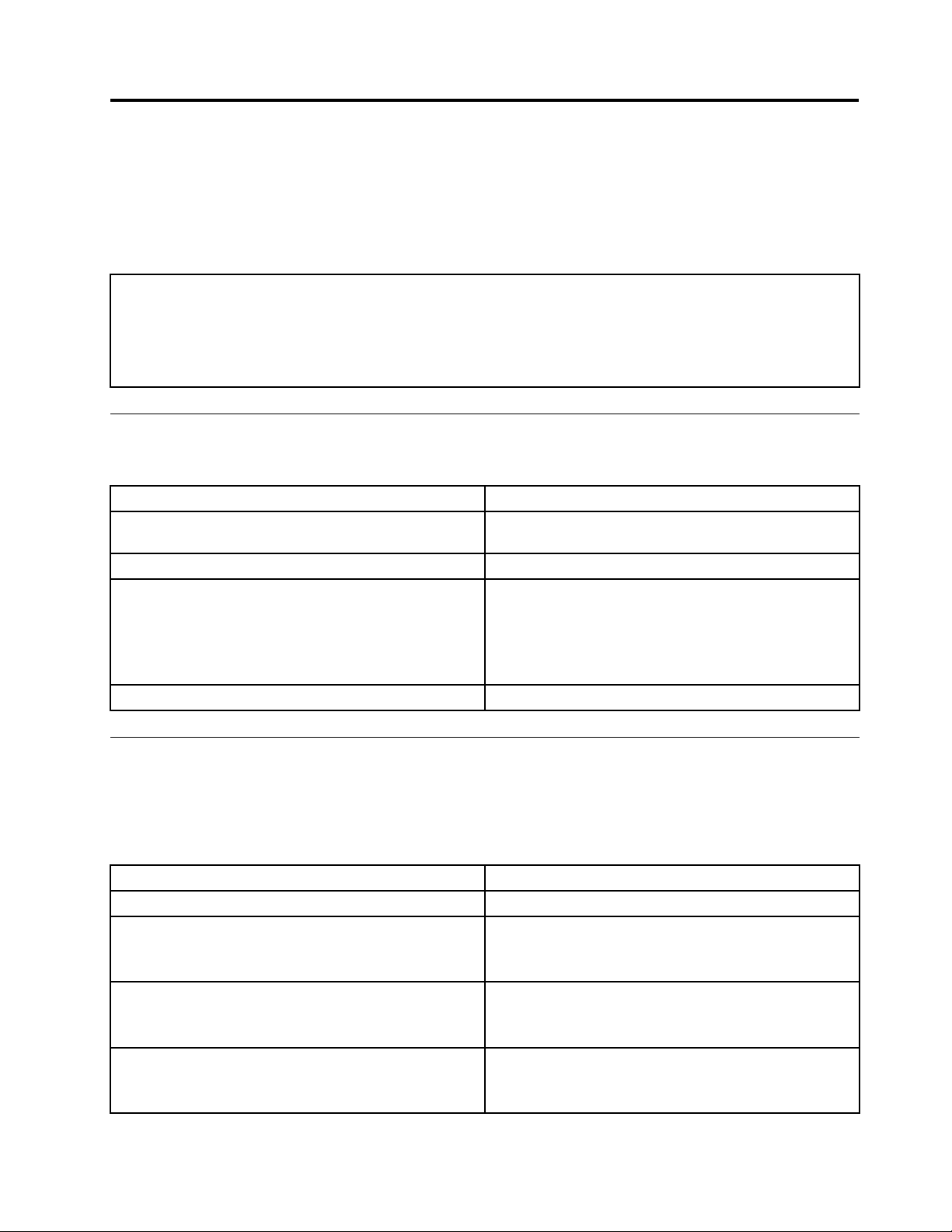
Harddiskdrivebooterror
Aharddiskdrivebooterror(errorcodes1962andI999030X)canhavethefollowingcauses.
ErrorFRU/Action
Thestart-updriveisnotinthebootsequencein
conguration.
Nooperatingsysteminstalledonthebootdrive.Installanoperatingsystemonthebootdrive.
Thebootsectoronthestart-updriveiscorrupted.
Thedriveisdefective.
Checkthecongurationandensurethestart-updriveis
inthebootsequence.
Thedrivemustbeformatted.Dothefollowing:
1.Attempttobackupthedataonthefailingharddisk
2.Usingtheoperatingsystemprograms,formatthe
Replacetheharddiskdrive.
.Youcanusethisindextohelpyoudecide
drive.
harddiskdrive.
Diagnosticerrorcodes
Refertothefollowingdiagnosticerrorcodeswhenusingthediagnostictests.See“Runningtests”onpage
39forthespecictypeforinformationaboutthediagnosticprograms.
Inthefollowingindex,Xcanrepresentanynumber.
DiagnosticerrorcodeFRU/Action
000-000-XXXBIOST estPassed
000-002-XXXBIOSTimeout1.Flashthesystem.See“Updating(ashing)BIOS
000-024-XXXBIOSAddressingtestfailure1.Flashthesystem.See“Updating(ashing)BIOS
000-025-XXXBIOSChecksumValueerror1.Flashthesystem.See“Updating(ashing)BIOS
©CopyrightLenovo2009,2010
Noaction
fromadisc”onpage99
2.Systemboard
fromadisc”onpage99
2.Systemboard
fromadisc”onpage99
2.Systemboard
45
Page 52

DiagnosticerrorcodeFRU/Action
000-026-XXXFLASHdataerror1.Flashthesystem.See“Updating(ashing)BIOS
fromadisc”onpage99
2.Systemboard
000-027-XXXBIOSConguration/Setuperror1.RunSetup
2.Flashthesystem.See“Updating(ashing)BIOS
fromadisc”onpage99
3.Systemboard
000-034-XXXBIOSBufferAllocationfailure
000-035-XXXBIOSResetConditiondetected1.Flashthesystem.See“Updating(ashing)BIOS
000-036-XXXBIOSRegistererror1.Flashthesystem.See“Updating(ashing)BIOS
000-038-XXXBIOSExtensionfailure1.Flashthesystem.See“Updating(ashing)BIOS
000-039-XXXBIOSDMIdataerror1.Flashthesystem.See“Updating(ashing)BIOS
000-195-XXXBIOSTestabortedbyuser
000-196-XXXBIOStesthalt,errorthresholdexceeded
000-197-XXXBIOStestwarning
000-198-XXXBIOStestaborted
000-199-XXXBIOStestfailed,causeunknown1.Goto“Undeterminedproblems”onpage64
1.Rebootthesystem
2.Flashthesystem.See“Updating(ashing)BIOS
fromadisc”onpage99
3.Runmemorytest
4.Systemboard
fromadisc”onpage99
2.Systemboard
fromadisc”onpage99
2.Systemboard
fromadisc”onpage99
2.Adaptercard
3.Systemboard
fromadisc”onpage99
2.Systemboard
InformationonlyRe-startthetest,ifnecessary
1.PressF3toreviewthelogle
2.Re-startthetesttoresetthelogle
1.Makesurethecomponentthatiscalledoutis
connectedand/orenabled.SeeChapter6“Usingthe
SetupUtility”onpage41
2.Re-runtest
3.Replacethecomponentthatiscalledoutinwarning
statement
4.Replacethecomponentundertest
1.Makesurethecomponentthatiscalledoutis
connectedand/orenabled.SeeChapter6“Usingthe
SetupUtility”onpage41
2.Flashthesystemandretest.See“Updating(ashing)
BIOSfromadisc”onpage99
3.Goto“Undeterminedproblems”onpage64
2.Flashthesystemandre-test
3.Replacecomponentunderfunctiontest
46HardwareMaintenanceManual
Page 53
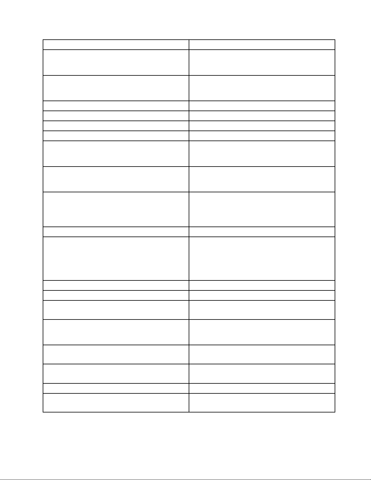
DiagnosticerrorcodeFRU/Action
000-250-XXXBIOSAPMfailure1.Flashthesystem.See“Updating(ashing)BIOS
fromadisc”onpage99
2.Systemboard
000-270-XXXBIOSACPIfailure1.Flashthesystem.See“Updating(ashing)BIOS
fromadisc”onpage99
2.Systemboard
001-000-XXXSystemtestpassed
Noaction
001-00X-XXXSystemerrorSystemboard
001-01X-XXXSystemerrorSystemboard
001-024-XXXSystemaddressingtestfailureSystemboard
001-025-XXXSystemchecksumvalueerror1.Flashthesystem.See“Updating(ashing)BIOS
fromadisc”onpage99
2.Systemboard
001-026-XXXSystemFLASHdataerror1.Flashthesystem.See“Updating(ashing)BIOS
fromadisc”onpage99
2.Systemboard
001-027-XXXSystemconguration/setuperror1.RunSetup
2.Flashthesystem.See“Updating(ashing)BIOS
fromadisc”onpage99
3.Systemboard
001-032-XXXSystemdevicecontrollerfailureSystemboard
001-034-XXXSystemdevicebufferallocationfailure
1.Rebootthesystem
2.Flashthesystem.See“Updating(ashing)BIOS
fromadisc”onpage99
3.Runmemorytest
4.Systemboard
001-035-XXXSystemdeviceresetconditiondetectedSystemboard
001-036-XXXSystemregistererrorSystemboard
001-038-XXXSystemextensionfailure
1.Adaptercard
2.Systemboard
001-039-XXXSystemDMIdatastructureerror1.Flashthesystem.See“Updating(ashing)BIOS
fromadisc”onpage99
2.Systemboard
001-040-XXXSystemIRQfailure1.Power-off/onsystemandre-test
2.Systemboard
001-041-XXXSystemDMAfailure1.Power-off/onsystemandre-test
2.Systemboard
001-195-XXXSystemtestabortedbyuser
001-196-XXXSystemtesthalt,errorthresholdexceeded
InformationonlyRe-startthetest,ifnecessary
1.PressF3toreviewthelogle
2.Re-startthetesttoresetthelogle
Chapter7.Symptom-to-FRUindex47
Page 54
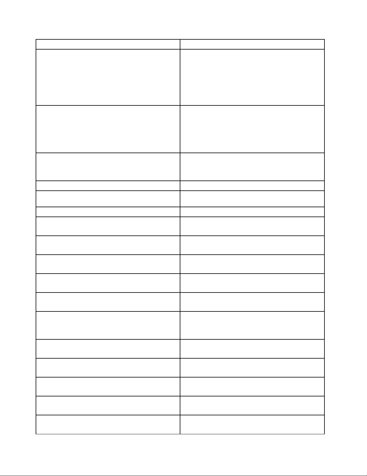
DiagnosticerrorcodeFRU/Action
001-197-XXXSystemtestwarning
001-198-XXXSystemtestaborted
001-199-XXXSystemtestfailed,causeunknown1.Goto“Undeterminedproblems”onpage64
001-250-XXXSystemECCerrorSystemboard
001-254-XXX001-255-XXX001-256-XXX001-257-XXX
SystemDMAerror
001-260-XXX001-264-XXXSystemIRQerrorSystemboard
001-268-XXXSystemIRQ1failure1.DeviceonIRQ1
001-269-XXXSystemIRQ2failure1.DeviceonIRQ2
001-270-XXXSystemIRQ3failure1.DeviceonIRQ3
001-271-XXXSystemIRQ4failure1.DeviceonIRQ4
001-272-XXXSystemIRQ5failure1.DeviceonIRQ5
001-273-XXXSystemIRQ6(diskettedrive)failure1.DisketteCable
001-274-XXXSystemIRQ7failure1.DeviceonIRQ7
001-275-XXXSystemIRQ8failure1.DeviceonIRQ8
001-276-XXXSystemIRQ9failure1.DeviceonIRQ9
001-277-XXXSystemIRQ10failure1.DeviceonIRQ10
001-278-XXXSystemIRQ11failure1.DeviceonIRQ11
1.Makesurethecomponentthatiscalledoutis
connectedand/orenabled.SeeChapter6“Usingthe
SetupUtility”onpage41
2.Re-runtest
3.Replacethecomponentthatiscalledoutinwarning
statement
4.Replacethecomponentundertest
1.Ifacomponentiscalledout,makesureitis
connectedand/orenabled.SeeChapter6“Usingthe
SetupUtility”onpage41
2.Flashthesystemandretest.See“Updating(ashing)
BIOSfromadisc”onpage99
3.Goto“Undeterminedproblems”onpage64
2.Flashthesystemandre-test
3.Replacecomponentunderfunctiontest
Systemboard
2.Systemboard
2.Systemboard
2.Systemboard
2.Systemboard
2.Systemboard
2.Diskettedrive
3.Systemboard
2.Systemboard
2.Systemboard
2.Systemboard
2.Systemboard
2.Systemboard
48HardwareMaintenanceManual
Page 55
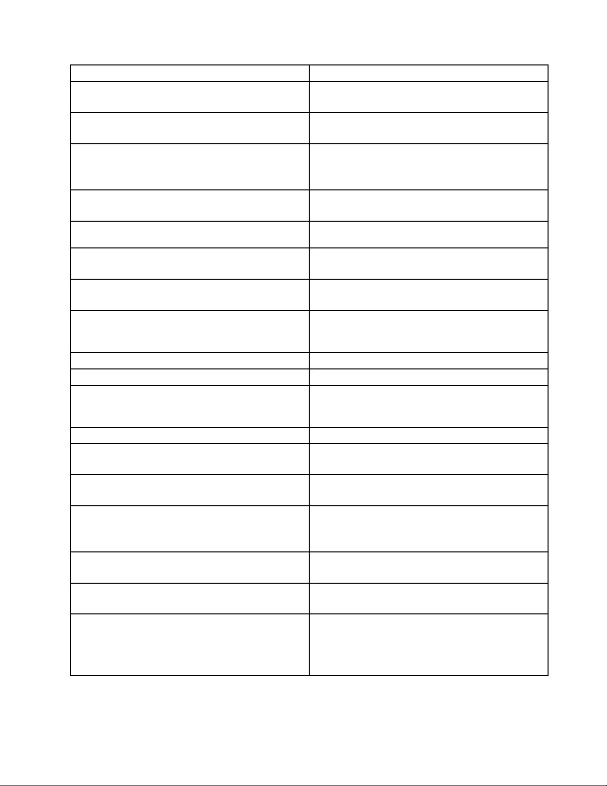
DiagnosticerrorcodeFRU/Action
001-279-XXXSystemIRQ12failure1.DeviceonIRQ12
2.Systemboard
001-280-XXXSystemIRQ13failure1.DeviceonIRQ13
2.Systemboard
001-281-XXXSystemIRQ14(harddiskdrive)failure
1.Harddiskdrivecable
2.Harddiskdrive
3.Systemboard
001-282-XXXSystemIRQ15failure1.DeviceonIRQ15
2.Systemboard
001-286-XXX001-287-XXX001-288-XXXSystemTimer
Systemboard
failure
001-292-XXXSystemCMOSRAMerror1.RunSetupandre-test
2.Systemboard
001-293-XXXSystemCMOSBattery1.CMOSBattery
2.Systemboard
001-298-XXXSystemRTCdate/timeupdatefailure1.Flashthesystem.See“Updating(ashing)BIOS
fromadisc”onpage99
2.Systemboard
001-299-XXXSystemRTCperiodicinterruptfailureSystemboard
001-300-XXXSystemRTCAlarmfailureSystemboard
001-301-XXXSystemRTCCenturybyteerror1.Flashthesystem.See“Updating(ashing)BIOS
fromadisc”onpage99
2.Systemboard
005-000-XXXVideotestpassedNoaction
005-00X-XXXVideoerror
1.Videocard,ifinstalled
2.Systemboard
005-010-XXX005-011-XXX005-012-XXX005-013-XXX
Videosignalfailure
005-016-XXXVideosimplepatterntestfailure
1.Videocard,ifinstalled
2.Systemboard
1.VideoRam
2.Videocard,ifinstalled
3.Systemboard
005-024-XXXVideoaddressingtestfailure1.Videocard,ifinstalled
2.Systemboard
005-025-XXXVideochecksumvalueerror
1.Videocard,ifinstalled
2.Systemboard
005-027-XXXVideoconguration/setuperror1.RunSetup
2.Videodriversupdate
3.Videocard,ifinstalled
4.Systemboard
Chapter7.Symptom-to-FRUindex49
Page 56
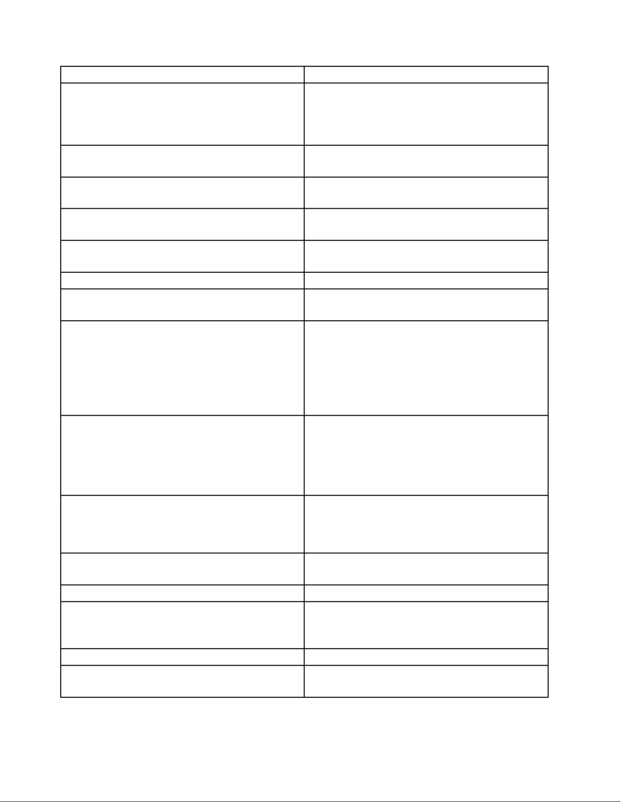
DiagnosticerrorcodeFRU/Action
005-031-XXXVideodevicecablefailure
005-032-XXXVideodevicecontrollerfailure1.Videocard,ifinstalled
005-036-XXXVideoregistererror
005-038-XXXSystemBIOSextensionfailure
005-040-XXXVideoIRQfailure
005-195-XXXVideotestabortedbyuser
005-196-XXXVideotesthalt,errorthresholdexceeded
005-197-XXXVideotestwarning1.Makesurethecomponentthatiscalledoutis
005-198-XXXVideotestaborted
005-199-XXXVideotestfailed,causeunknown
005-2XX-XXX005-3XX-XXXVideosubsystemerror
006-000-XXXDisketteinterfaceT estPassed
006-0XX-XXXDisketteinterfaceerror
006-195-XXXDisketteinterfaceTestabortedbyuserInformationonlyRe-startthetest,ifnecessary
006-196-XXXDisketteinterfacetesthalt,errorthreshold
exceeded
1.Videocable
2.Monitor
3.Videocard,ifinstalled
4.Systemboard
2.Systemboard
1.Videocard,ifinstalled
2.Systemboard
1.Videocard,ifinstalled
2.Systemboard
1.Videocard,ifinstalled
2.Systemboard
InformationonlyRe-startthetest,ifnecessary
1.PressF3toreviewthelogle
2.Re-startthetesttoresetthelogle
connectedand/orenabled.SeeChapter6“Usingthe
SetupUtility”onpage41
2.Re-runtest
3.Replacethecomponentcalledoutinwarning
statement
4.Replacethecomponentundertest
1.Ifacomponentiscalledout,makesureitis
connectedand/orenabled.SeeChapter6“Usingthe
SetupUtility”onpage41
2.Flashthesystemandre-test.See“Updating
(ashing)BIOSfromadisc”onpage99
3.Goto“Undeterminedproblems”onpage64
1.Goto“Undeterminedproblems”onpage64
2.Flashthesystemandre-test.See“Updating
(ashing)BIOSfromadisc”onpage99
3.Replacecomponentunderfunctiontest
1.Videocard,ifinstalled
2.Systemboard
Noaction
1.DiskettedriveCable
2.Diskettedrive
3.Systemboard
1.PressF3toreviewthelogle
2.Re-startthetesttoresetthelogle
50HardwareMaintenanceManual
Page 57
DiagnosticerrorcodeFRU/Action
006-197-XXXDisketteinterfacetestwarning1.Ifacomponentiscalledout,makesureitis
connectedand/orenabled
2.Re-runtest
3.Replacethecomponentthatiscalledoutinwarning
statement
4.Replacethecomponentundertest
006-198-XXXDisketteinterfacetestaborted1.Ifacomponentiscalledout,makesureitis
connectedand/orenabled
2.Flashthesystemandre-test.See“Updating
(ashing)BIOSfromadisc”onpage99
3.Goto“Undeterminedproblems”onpage64
006-199-XXXDisketteinterfacetestfailed,cause
unknown
1.Goto“Undeterminedproblems”onpage64
2.Flashthesystemandre-test
3.Replacecomponentunderfunctiontest
006-25X-XXXDisketteinterfaceError
1.Diskettedrivecable
2.Diskettedrive
3.Systemboard
015-000-XXXUSBportinterfaceTestPassed
Noaction
015-001-XXXUSBportpresence1.RemoveUSBdevice(s)andre-test
2.Systemboard
015-002-XXXUSBporttimeout1.RemoveUSBdevice(s)andre-test
2.Systemboard
015-015-XXXUSBportexternalloopbackfailure1.RemoveUSBdevice(s)andre-test
2.Systemboard
015-027-XXXUSBportconguration/setuperror1.Flashthesystem.See“Updating(ashing)BIOS
fromadisc”onpage99
2.Systemboard
015-032-XXXUSBportdevicecontrollerfailureSystemboard
015-034-XXXUSBportbufferallocationfailure
1.Rebootthesystem
2.Flashthesystemandre-test.See“Updating
(ashing)BIOSfromadisc”onpage99
3.Runmemorytest
4.Systemboard
015-035-XXXUSBportresetconditiondetected1.RemoveUSBdevice(s)andre-test
2.Systemboard
015-036-XXXUSBportregistererrorSystemboard
015-040-XXXUSBportIRQfailure
1.Runsetupandcheckforconicts
2.Flashthesystem.See“Updating(ashing)BIOS
fromadisc”onpage99
3.Systemboard
015-195-XXXUSBporttestabortedbyuser
015-196-XXXUSBporttesthalt,errorthresholdexceeded
InformationonlyRe-startthetest,ifnecessary
1.PressF3toreviewthelogle
2.Re-startthetesttoresetthelogle
Chapter7.Symptom-to-FRUindex51
Page 58
DiagnosticerrorcodeFRU/Action
015-197-XXXUSBporttestwarning
015-198-XXXUSBporttestaborted
015-199-XXXUSBporttestfailed,causeunknown1.Goto“Undeterminedproblems”onpage64
018-000-XXXPCIcardtestpassed
018-0XX-XXXPCIcardfailure
018-195-XXXPCIcardtestabortedbyuser1.PCIcard
018-196-XXXPCIcardtesthalt,errorthresholdexceeded
018-197-XXXPCIcardtestwarning
018-198-XXXPCIcardtestaborted
018-199-XXXPCIcardtestfailed,causeunknown1.Goto“Undeterminedproblems”onpage64
018-250-XXXPCIcardserviceserror1.PCIcard
020-000-XXXPCIinterfacetestpassed
1.Makesurethecomponentthatiscalledoutis
connectedand/orenabled.SeeChapter6“Usingthe
SetupUtility”onpage41
2.Re-runtest
3.Replacethecomponentthatiscalledoutinwarning
statement
4.Replacethecomponentundertest
1.Ifacomponentiscalledout,makesureitis
connectedand/orenabled.SeeChapter6“Usingthe
SetupUtility”onpage41
2.Flashthesystemandre-test.See“Updating
(ashing)BIOSfromadisc”onpage99
3.Goto“Undeterminedproblems”onpage64
2.Flashthesystemandre-test.See“Updating
(ashing)BIOSfromadisc”onpage99
3.Replacecomponentunderfunctiontest
Noaction
1.Risercard,ifinstalled
2.Systemboard
2.InformationonlyRe-startthetest,ifnecessary
1.PressF3toreviewthelogle
2.Re-startthetesttoresetthelogle
1.Makesurethecomponentthatiscalledoutis
connectedand/orenabled.SeeChapter6“Usingthe
SetupUtility”onpage41
2.Re-runtest
3.Replacethecomponentthatiscalledoutinwarning
statement
4.Replacethecomponentundertest
1.Ifacomponentiscalledout,makesureitis
connectedand/orenabled.SeeChapter6“Usingthe
SetupUtility”onpage41
2.Flashthesystemandre-test.See“Updating
(ashing)BIOSfromadisc”onpage99
3.Goto“Undeterminedproblems”onpage64
2.Flashthesystemandre-test.See“Updating
(ashing)BIOSfromadisc”onpage99
3.Replacecomponentunderfunctiontest
2.Risercard,ifinstalled
3.Systemboard
Noaction
52HardwareMaintenanceManual
Page 59

DiagnosticerrorcodeFRU/Action
020-0XX-XXXPCIinterfaceerror1.PCIcard
2.Risercard,ifinstalled
3.Systemboard
020-195-XXXPCItestabortedbyuser
020-196-XXXPCItesthalt,errorthresholdexceeded
InformationonlyRe-startthetest,ifnecessary
1.PressF3toreviewthelogle
2.Re-startthetesttoresetthelogle
020-197-XXXPCItestwarning
1.Makesurethecomponentthatiscalledoutis
connectedand/orenabled.SeeChapter6“Usingthe
SetupUtility”onpage41
2.Re-runtest
3.Replacethecomponentthatiscalledoutinwarning
statement
4.Replacethecomponentundertest
020-198-XXXPCItestaborted
1.Ifacomponentiscalledout,makesureitis
connectedand/orenabled.SeeChapter6“Usingthe
SetupUtility”onpage41
2.Flashthesystemandre-test.See“Updating
(ashing)BIOSfromadisc”onpage99
3.Goto“Undeterminedproblems”onpage64
020-199-XXXPCItestfailed,causeunknown1.Goto“Undeterminedproblems”onpage64
2.Flashthesystemandre-test.See“Updating
(ashing)BIOSfromadisc”onpage99
3.Replacecomponentunderfunctiontest
020-262-XXXPCIsystemerror1.PCIcard
2.Risercard,ifinstalled
3.Systemboard
025-000-XXXIDEinterfaceTestPassed
025-00X-XXX025-01X-XXXIDEinterfacefailure
Noaction
1.IDEsignalcable
2.Checkpowersupplyvoltages
3.ReseatIDEsignalcable
4.IDEdevice
5.Systemboard
025-027-XXXIDEinterfaceConguration/Setuperror
1.IDEsignalcable
2.Flashthesystem.See“Updating(ashing)BIOS
fromadisc”onpage99
3.ReseatIDEsignalcable
4.IDEdevice
5.Systemboard
025-02X-XXX025-03X-XXX025-04X-XXXIDEInterface
failure
1.IDEsignalcable
2.CheckAC/DCpoweradapter
3.ReseatIDEsignalcable
4.IDEdevice
5.Systemboard
025-195-XXXIDEinterfaceT estabortedbyuserInformationonlyRe-startthetest,ifnecessary
Chapter7.Symptom-to-FRUindex53
Page 60

DiagnosticerrorcodeFRU/Action
025-196-XXXIDEinterfacetesthalt,errorthreshold
exceeded
025-197-XXXIDEinterfacetestwarning
025-198-XXXIDEinterfacetestaborted1.Ifacomponentiscalledout,makesureitis
025-199-XXXIDEinterfacetestfailed,causeunknown
030-000-XXXSCSIinterfaceTestPassed
030-00X-XXX030-01X-XXXSCSIinterfacefailure1.SCSIsignalcable
030-027-XXXSCSIinterfaceconguration/setuperror1.SCSIsignalcable
030-03X-XXX030-04X-XXXSCSIinterfaceerror1.SCSIsignalcable
030-195-XXXSCSIinterfacetestabortedbyuser
030-196-XXXSCSIinterfacetesthalt,errorthreshold
exceeded
1.PressF3toreviewthelogle
2.Re-startthetesttoresetthelogle
1.Makesurethecomponentthatiscalledoutis
connectedand/orenabled.SeeChapter6“Usingthe
SetupUtility”onpage41
2.Re-runtest
3.Replacethecomponentthatiscalledoutinwarning
statement
4.Replacethecomponentundertest
connectedand/orenabled.SeeChapter6“Usingthe
SetupUtility”onpage41
2.Flashthesystemandre-test.See“Updating
(ashing)BIOSfromadisc”onpage99
3.Goto“Undeterminedproblems”onpage64
1.Goto“Undeterminedproblems”onpage64
2.Flashthesystemandre-test.See“Updating
(ashing)BIOSfromadisc”onpage99
3.Replacecomponentunderfunctiontest
Noaction
2.CheckAC/DCpoweradapter
3.SCSIdevice
4.SCSIadaptercard,ifinstalled
5.Systemboard
2.Flashthesystem.See“Updating(ashing)BIOS
fromadisc”onpage99
3.SCSIdevice
4.SCSIadaptercard,ifinstalled
5.Systemboard
2.CheckAC/DCpoweradapter
3.SCSIdevice
4.SCSIadaptercard,ifinstalled
5.Systemboard
InformationonlyRe-startthetest,ifnecessary
1.PressF3toreviewthelogle
2.Re-startthetesttoresetthelogle
54HardwareMaintenanceManual
Page 61
DiagnosticerrorcodeFRU/Action
030-197-XXXSCSIinterfacetestwarning
1.Makesurethecomponentthatiscalledoutis
connectedand/orenabled.SeeChapter6“Usingthe
SetupUtility”onpage41
2.Re-runtest
3.Replacethecomponentthatiscalledoutinwarning
statement
4.Replacethecomponentundertest
030-198-XXXSCSIinterfacetestaborted
1.Ifacomponentiscalledout,makesureitis
connectedand/orenabled.SeeChapter6“Usingthe
SetupUtility”onpage41
2.Flashthesystemandre-test.See“Updating
(ashing)BIOSfromadisc”onpage99
3.Goto“Undeterminedproblems”onpage64
030-199-XXXSCSIinterfacetestfailed,causeunknown1.Goto“Undeterminedproblems”onpage64
2.Flashthesystemandre-test.See“Updating
(ashing)BIOSfromadisc”onpage99
3.Replacecomponentunderfunctiontest
035-000-XXXRAIDinterfacetestpassed
035-0XX-XXXRAIDinterfaceFailure
Noaction
1.RAIDsignalcable
2.RAIDdevice
3.RAIDadaptercard,ifinstalled
4.Systemboard
035-195-XXXRAIDinterfacetestabortedbyuserInformationonlyRe-startthetest,ifnecessary
035-196-XXXRAIDinterfacetesthalt,errorthreshold
exceeded
035-197-XXXRAIDinterfacetestwarning
1.PressF3toreviewthelogle
2.Re-startthetesttoresetthelogle
1.Makesurethecomponentthatiscalledoutis
connectedand/orenabled.SeeChapter6“Usingthe
SetupUtility”onpage41
2.Re-runtest
3.Replacethecomponentthatiscalledoutinwarning
statement
4.Replacethecomponentundertest
035-198-XXXRAIDinterfacetestaborted1.Ifacomponentiscalledout,makesureitis
connectedand/orenabled.SeeChapter6“Usingthe
SetupUtility”onpage41
2.Flashthesystemandre-test.See“Updating
(ashing)BIOSfromadisc”onpage99
3.Goto“Undeterminedproblems”onpage64
035-199-XXXRAIDinterfacetestfailed,causeunknown
1.See“Undeterminedproblems”onpage64
2.Flashthesystemandre-test.See“Updating
(ashing)BIOSfromadisc”onpage99
3.Replacecomponentunderfunctiontest
071-000-XXXAudioportinterfacetestpassed
Noaction
Chapter7.Symptom-to-FRUindex55
Page 62

DiagnosticerrorcodeFRU/Action
071-00X-XXX071-01X-XXX071-02X-XXXAudioport
error
071-03X-XXXAudioportfailure
071-04X-XXXAudioportfailure
071-195-XXXAudioporttestabortedbyuser
071-196-XXXAudioporttesthalt,errorthreshold
exceeded
071-197-XXXAudioporttestwarning1.Makesurethecomponentthatiscalledoutis
071-198-XXXAudioporttestaborted
071-199-XXXAudioporttestfailed,causeunknown
071-25X-XXXAudioportfailure
080-000-XXXGameportinterfacetestpassed
080-XXX-XXXGameportinterfaceerror
080-195-XXXGameportinterfacetestabortedbyuser
080-196-XXXGamePortinterfacetesthalt,error
thresholdexceeded
1.RunSetup
2.Flashthesystem.See“Updating(ashing)BIOS
fromadisc”onpage99
3.Systemboard
1.Speakers
2.Microphone
3.Audiocard,ifinstalled
4.Systemboard
1.RunSetup
2.Audiocard,ifinstalled
3.Systemboard
InformationonlyRe-startthetest,ifnecessary
1.PressF3toreviewthelogle
2.Re-startthetesttoresetthelogle
connectedand/orenabled.SeeChapter6“Usingthe
SetupUtility”onpage41
2.Re-runtest
3.Replacethecomponentthatiscalledoutinwarning
statement
4.Replacethecomponentundertest
1.Ifacomponentiscalledout,makesureitis
connectedand/orenabled.SeeChapter6“Usingthe
SetupUtility”onpage41
2.Flashthesystemandre-test.See“Updating
(ashing)BIOSfromadisc”onpage99
3.Goto“Undeterminedproblems”onpage64
1.See“Undeterminedproblems”onpage64
2.Flashthesystemandre-test.See“Updating
(ashing)BIOSfromadisc”onpage99
3.Replacecomponentunderfunctiontest
1.Speakers
2.Audiocard,ifinstalled
3.Systemboard
Noaction
1.Removethegameportdeviceandre-testthesystem
InformationonlyRe-startthetest,ifnecessary
1.PressF3toreviewthelogle
2.Re-startthetesttoresetthelogle
56HardwareMaintenanceManual
Page 63
DiagnosticerrorcodeFRU/Action
080-197-XXXGameportinterfacetestwarning
1.Makesurethecomponentthatiscalledoutis
connectedand/orenabled.SeeChapter6“Usingthe
SetupUtility”onpage41
2.Re-runtest
3.Replacethecomponentthatiscalledoutinwarning
statement
4.Replacethecomponentundertest
080-198-XXXGameportinterfacetestaborted
1.Ifacomponentiscalledout,makesureitis
connectedand/orenabled.SeeChapter6“Usingthe
SetupUtility”onpage41
2.Flashthesystemandre-test.See“Updating
(ashing)BIOSfromadisc”onpage99
3.Goto“Undeterminedproblems”onpage64
080-199-XXXGameportinterfacetestfailed,cause
unknown
1.See“Undeterminedproblems”onpage64
2.Flashthesystemandre-test.See“Updating
(ashing)BIOSfromadisc”onpage99
3.Replacecomponentunderfunctiontest
086-000-XXXMouseportinterfacetestpassed
086-001-XXXMouseportinterfacepresence
Noaction
1.Mouse
2.Systemboard
086-032-XXXMouseportinterfacedevicecontroller
failure
086-035-XXXMouseportinterfaceReset
1.Mouse
2.Systemboard
1.Mouse
2.Systemboard
086-040-XXXMouseportinterfaceIRQfailure1.RunSetup
2.Mouse
3.Systemboard
086-195-XXXMouseportinterfacetestabortedbyuserInformationonlyRe-startthetest,ifnecessary
086-196-XXXMouseportinterfacetesthalt,error
thresholdexceeded
086-197-XXXMouseportinterfacetestwarning
1.PressF3toreviewthelogle
2.Re-startthetesttoresetthelogle
1.Makesurethecomponentthatiscalledoutis
connectedand/orenabled.SeeChapter6“Usingthe
SetupUtility”onpage41
2.Re-runtest
3.Replacethecomponentthatiscalledoutinwarning
statement
4.Replacethecomponentundertest
086-198-XXXMouseportinterfacetestaborted1.Ifacomponentiscalledout,makesureitis
connectedand/orenabled.SeeChapter6“Usingthe
SetupUtility”onpage41
2.Flashthesystemandre-test.See“Updating
(ashing)BIOSfromadisc”onpage99
3.Goto“Undeterminedproblems”onpage64
Chapter7.Symptom-to-FRUindex57
Page 64
DiagnosticerrorcodeFRU/Action
086-199-XXXMouseportinterfacetestfailed,cause
unknown
089-000-XXXMicroprocessortestpassedNoaction
089-XXX-XXXMicroprocessorfailure
089-195-XXXMicroprocessortestabortedbyuser
089-196-XXXMicroprocessortesthalt,errorthreshold
exceeded
089-197-XXXMicroprocessortestwarning1.Makesurethecomponentthatiscalledoutis
089-198-XXXMicroprocessortestaborted
089-199-XXXMicroprocessortestfailed,causeunknown
170-000-XXXVoltagesensor(s)testpassed
170-0XX-XXXVoltagesensor(s)failure
170-195-XXXVoltagesensor(s)testabortedbyuser
170-196-XXXVoltagesensor(s)testhalt,errorthreshold
exceeded
170-197-XXXVoltagesensor(s)testwarning
170-198-XXXVoltagesensor(s)testaborted
1.See“Undeterminedproblems”onpage64
2.Flashthesystemandre-test.See“Updating
(ashing)BIOSfromadisc”onpage99
3.Replacecomponentunderfunctiontest
1.Microprocessor(s)
2.Systemboard
InformationonlyRe-startthetest,ifnecessary
1.PressF3toreviewthelogle
2.Re-startthetesttoresetthelogle
connectedand/orenabled.SeeChapter6“Usingthe
SetupUtility”onpage41
2.Re-runtest
3.Replacethecomponentthatiscalledoutinwarning
statement
4.Replacethecomponentundertest
1.Flashthesystem.See“Updating(ashing)BIOS
fromadisc”onpage99
2.Goto“Undeterminedproblems”onpage64
1.See“Undeterminedproblems”onpage64
2.Flashthesystemandre-test.See“Updating
(ashing)BIOSfromadisc”onpage99
3.Replacecomponentunderfunctiontest
Noaction
1.Flashsystem
2.Systemboard
InformationonlyRe-startthetest,ifnecessary
1.PressF3toreviewthelogle
2.Re-startthetesttoresetthelogle
1.Makesurethecomponentthatiscalledoutis
connectedand/orenabled.SeeChapter6“Usingthe
SetupUtility”onpage41
2.Re-runtest
3.Replacethecomponentthatiscalledoutinwarning
statement
4.Replacethecomponentundertest
1.Ifacomponentiscalledout,makesureitis
connectedand/orenabled.SeeChapter6“Usingthe
SetupUtility”onpage41
2.Flashthesystemandre-test.See“Updating
(ashing)BIOSfromadisc”onpage99
3.Goto“Undeterminedproblems”onpage64
58HardwareMaintenanceManual
Page 65
DiagnosticerrorcodeFRU/Action
170-199-XXXVoltagesensor(s)testfailed,cause
unknown
1.See“Undeterminedproblems”onpage64
2.Flashthesystemandre-test.See“Updating
(ashing)BIOSfromadisc”onpage99
3.Replacecomponentunderfunctiontest
170-250-XXX170-251-XXXVoltagesensor(s)voltage
limiterror
170-254-XXXVoltagesensor(s)voltageregulatorModule
error
1.AC/DCpoweradapter
2.Systemboard
1.VoltageRegulatorModule(VRM)
2.Microprocessor
3.Systemboard
175-000-XXXThermalsensor(s)testpassed
175-0XX-XXXThermalsensor(s)failure
Noaction
1.Flashsystem
2.Systemboard
175-195-XXXThermalsensor(s)testabortedbyuser
175-196-XXXThermalsensor(s)testhalt,errorthreshold
exceeded
175-197-XXXThermalsensor(s)testwarning
InformationonlyRe-startthetest,ifnecessary
1.PressF3toreviewthelogle
2.Re-startthetesttoresetthelogle
1.Makesurethecomponentthatiscalledoutis
connectedand/orenabled.SeeChapter6“Usingthe
SetupUtility”onpage41
2.Re-runtest
3.Replacethecomponentthatiscalledoutinwarning
statement
4.Replacethecomponentundertest
175-198-XXXThermalsensor(s)testaborted
1.Ifacomponentiscalledout,makesureitis
connectedand/orenabled
2.Flashthesystemandre-test.See“Updating
(ashing)BIOSfromadisc”onpage99
3.Goto“Undeterminedproblems”onpage64
175-199-XXXThermalsensor(s)testfailed,cause
unknown
1.See“Undeterminedproblems”onpage64
2.Flashthesystemandre-test.See“Updating
(ashing)BIOSfromadisc”onpage99
3.Replacecomponentunderfunctiontest
175-250-XXX175-251-XXXThermalsensor(s)limiterror1.Checkfans
2.CheckAC/DCpoweradaptervoltages
3.Microprocessor
4.Systemboard
185-000-XXXAssetsecuritytestpassedNoaction
185-XXX-XXXAssetsecurityfailure
1.Flashsystem
2.Systemboard
185-278-XXXAssetsecuritychassisintrusion
1.AssureAssetSecurityEnabled
2.C2CoverSwitch
3.Systemboard
201-000-XXXSystemmemorytestpassed
Noaction
Chapter7.Symptom-to-FRUindex59
Page 66
DiagnosticerrorcodeFRU/Action
201-XXX-XXXSystemmemoryerror
202-000-XXXSystemcachetestpassed
202-XXX-XXXSystemcacheerror1.Cache,ifremovable
206-000-XXXDiskettedrivetestpassedNoaction
206-XXX-XXXDiskettedriveerror
215-000-XXXCD-ROMdrivetestpassed
215-XXX-XXXCD-ROMdriveerror1.CD-ROMDriveCable
217-000-XXXHarddiskdrivetestpassedNoaction
217-25X-XXX217-26X-XXXHarddiskdrive(IDE)error1.HardDiskDriveCable
217-28X-XXX217-29X-XXXHarddiskdrive(SCSI)error1.HardDiskDriveCable
220-000-XXXHi-Capacitycartridgedrivetestpassed
220-XXX-XXXHi-Capacitycartridgedriveerror1.RemovetheHi-CapacityCartridgeDriveandre-test
301-XXX-XXXKeyboarderror1.Keyboard
301-000-XXXKeyboardtestpassedNoaction
302-000-XXXMousetestpassedNoaction
302-XXX-XXXMouseerror1.Mouse
303-000-XXXJoysticktestpassedNoaction
303-XXX-XXXJoystickerrorRemovetheJoystickandre-testthesystem
1.Replacethememorymodulecalledoutbythetest
2.Systemboard
Noaction
2.Systemboard
3.Microprocessor
1.DisketteDriveCable
2.CheckAC/DCpoweradaptervoltages
3.Diskettedrive
4.Systemboard
Noaction
2.CheckAC/DCpoweradaptervoltages
3.CD-ROMdrive
4.Systemboard
2.CheckAC/DCpoweradaptervoltages
3.Reseattheharddiskdrivecable
4.HardDiskdrive(IDE)
5.Systemboard
2.CheckAC/DCpoweradaptervoltages
3.Reseattheharddiskdrivecable
4.HardDiskdrive(SCSI)
5.SCSIadaptercard
6.Systemboard
Noaction
thesystem
2.Checkandtestmouse
3.Systemboard
2.CheckandtestKeyboard
3.Systemboard
60HardwareMaintenanceManual
Page 67
DiagnosticerrorcodeFRU/Action
305-000-XXXMonitorDDCtestpassed
305-250-XXXMonitorDDCselftestfailure1.RunSetuptoenableDDC
415-000-XXXModemtestPassedNoaction
415-XXX-XXXModemerrorRemovetheModemandre-testthesystem
Noaction
2.Cable
3.Monitor
4.Videocard
5.Systemboard
Beepsymptoms
Beepsymptomsaretonesoraseriesoftonesseparatedbypauses(intervalswithoutsound)duringPOST.
Thefollowingtabledescribesbeepsymptoms.
BeepsymptomFRU/Action
1,2,or3beeps
4,5,6,or7beeps9,10,or11beeps
8beepsReplacethesystemboard.
Reseatthememorymodules.Iftheerrorpersists,replace
thememorymodulesoneatatimeuntilthefailingmodule
isdetermined.
Beforereplacingthesystemboard,removeanyoptional
adapters(Expresscard,Modemcard,Mediareader)and
retry.Iftheproblempersists,replacethesystemboard.
Otherwise,reinstalltheoptionaladaptersoneatatime
untilthefailingadapterisdetermined.
POSTerrorcodes
Eachtimeyoupower-onthesystem,itperformsaseriesofteststhatchecktheoperationofthesystemand
someoptions.ThisseriesoftestsiscalledthePower-OnSelf-Test,orPOST.
ThePOSTdoesthefollowingoperations:
•Checkssomebasicsystem-boardoperations
•Checksthememoryoperation
•Startsthevideooperation
•Veriesthatthebootdriveisworking
IfthePOSTdetectsaproblem,anerrormessageappearsonthescreen.Asingleproblemcancauseseveral
errormessagestoappear.Whenyoucorrectthecauseofthersterrormessage,theothererrormessages
probablywillnotappearonthescreenthenexttimeyouturnonthesystem.
Chapter7.Symptom-to-FRUindex61
Page 68
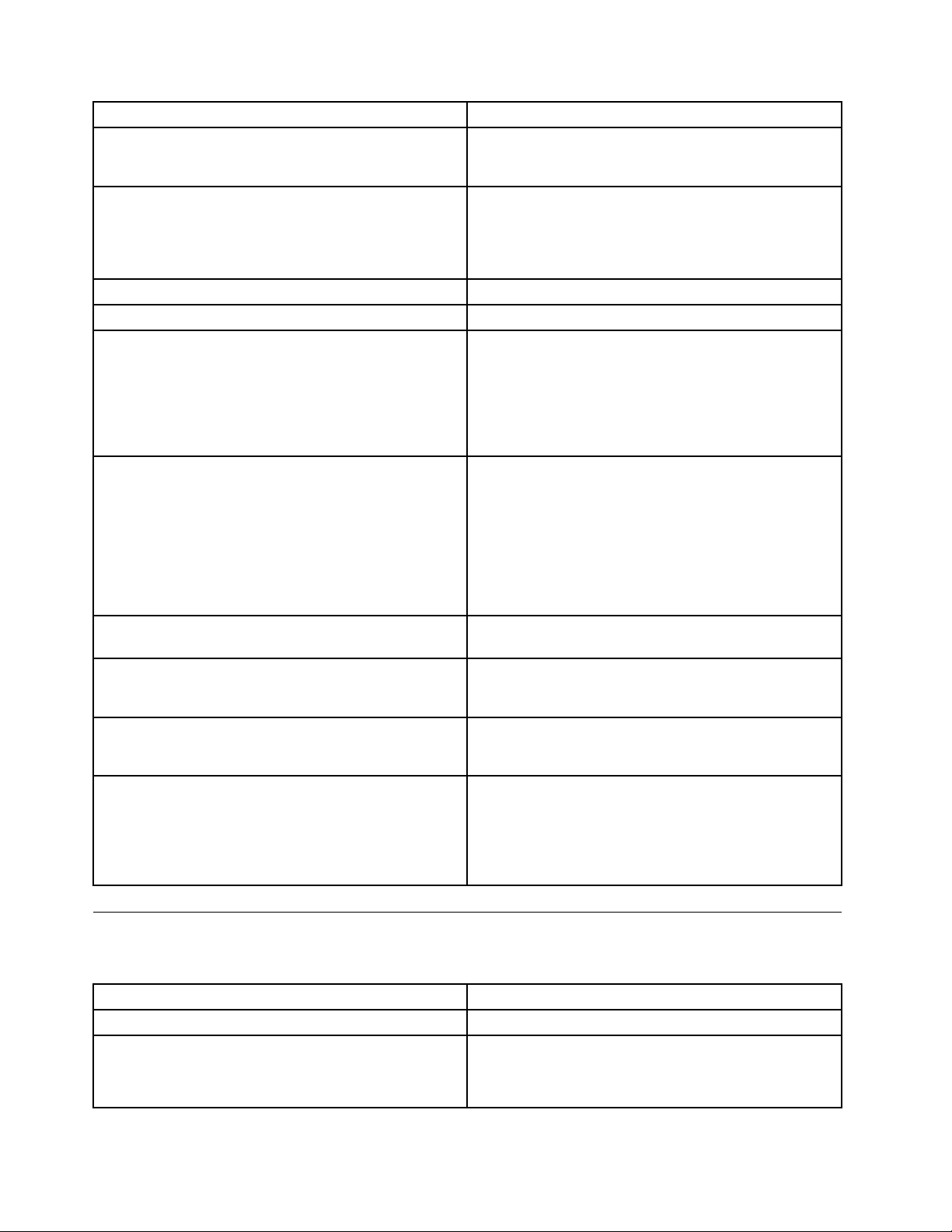
POSTerrormessageDescription/Action
CMOSbatteryfailedTheCMOSbatteryisnolongerfunctional.
Replacethebattery.
CMOSchecksumerror-defaultsloadedChecksumofCMOSisincorrect.
Thecomputerloadsthedefaultcongurationsettings.
ThiserrormightindicatethatCMOShasbecomecorrupt
duetoaweakCMOSbattery.
CPUatnnnn
PressEsctoskipmemorytest
HARDDISKINSTALLFAILURECannotndorinitializetheharddiskdrivecontrolleror
Keyboarderrorornokeyboardpresent
Memorytest:
Memorytestfail
PressT ABtoshowPOSTscreen
Error:Non-SystemdiskordiskerrorReplaceandpress
anykeywhenready
nnnnistherunningspeedofthemicroprocessor.
PressingEscskipsthefullmemorytest.
thedrive.
Makesuretheharddiskdriveiscorrectlyinstalled.
Ifnoharddiskdrivesareinstalled,makesurethehard
diskdriveselectioninsetupissettoNONE.
Cannotinitializethekeyboard.
Makesurethekeyboardiscorrectlyconnectedtothe
computerandthatnokeysareheldpressedduringPOST.
Topurposelycongurethecomputerwithoutakeyboard,
settheerrorhaltconditioninSetuptoHAL TONALL,BUT
KEYBOARD.TheBIOSthenignoresthemissingkeyboard
duringPOST.
Thismessagedisplaysduringafullmemorytest,counting
downthememoryareasbeingtested.
IfPOSTdetectsanerrorduringmemorytesting,additional
informationappears.Thisinformationgivesspecics
aboutthetypeandlocationofthememoryerror.
PressingtheTABkeypermitstheusertotogglebetween
thedefaultPOSTdisplayscreenandacustomPOST
displayscreen.
TheBIOSwasunabletondasuitablebootdevice.
Makesurethebootdriveiscorrectlyconnectedtothe
computer.
Makesureyouhavebootablemedia.
Miscellaneouserrormessages
Thefollowingtabledescribesmiscellaneouserrormessages.
Message/SymptomFRU/Action
ChangingdisplaycolorsDisplay/Monitor
Computerwillnotpower-off.See“Powerproblems”on
page33
.
62HardwareMaintenanceManual
1.Powerswitch
2.Systemboard
3.Risercard,ifinstalled
Page 69

Message/SymptomFRU/Action
ComputerwillnotPXEfromserver
1.Ensurethatnetworkisinstartupsequenceasrst
deviceorrstdeviceafterdiskette
2.EnsurethatnetworkadapterisenabledforPXE
3.Networkadapter(Advisenetworkadministratorof
newMACaddress).
ComputerwillnotperformaWakeonLAN(ifapplicable)1.Checkpowersupplyandsignalcableconnections
tonetworkadapter
2.Ensurethattheoperatingsystemsettingsaresetto
enabletheWakeOnLANoperation
3.EnsureWakeonLANfeatureisenabledin
Setup/Conguration(see“StartingtheSetupUtility
program”onpage41)
4.EnsurenetworkadministratorisusingcorrectMAC
address
5.EnsurenointerruptorI/Oaddressconicts
6.Networkadapter(advisenetworkadministratorof
newMACaddress)
Deadcomputer.See“Powerproblems”onpage33.1.AC/DCPowerAdapter
2.SystemBoard
Diskettedrivein-uselightremainsonordoesnotlight
whendriveisactive.
1.DisketteDrive
2.SystemBoard
3.DisketteDriveCable
Flashingcursorwithanotherwiseblankdisplay.
1.SystemBoard
2.PrimaryHardDiskDrive
3.HardDiskDriveCable
IncorrectmemorysizeduringPOST
1.RuntheMemorytests
2.MemoryModule
3.SystemBoard
"InsertaDiskette"iconappearswithaknown-good
diagnosticsdisketteintherst3.5-inchdiskettedrive.
1.SystemBoard
2.DisketteDriveCable
3.NetworkAdapter
Intensityorcolorvariesfromlefttorightofcharacters
andcolorbars
1.Display
2.Videoadapter(ifpresent)
3.SystemBoard
Nopowerorfannotrunning
Non-systemdiskordiskerror-typemessagewitha
known-gooddiagnosticdiskette.
1.See“Powerproblems”onpage33.
1.DisketteDrive
2.SystemBoard
3.DisketteDriveCable
Otherdisplaysymptomsnotlistedabove(includingblank
orillegibledisplay)
Power-onindicatororharddiskdrivein-uselightnoton,
butcomputerworkscorrectly
1.Display
2.SystemBoard
1.Powerswitch/LEDassembly
2.SystemBoard
Printerproblems1.Printer
2.SystemBoard
Chapter7.Symptom-to-FRUindex63
Page 70
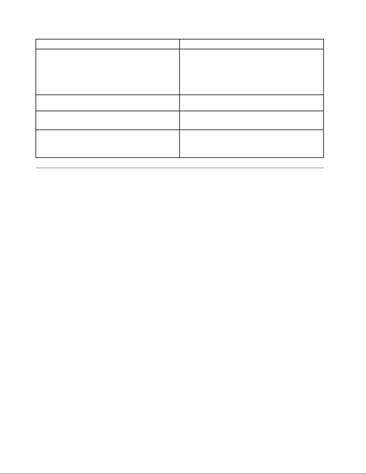
Message/SymptomFRU/Action
Programloadsfromtheharddiskwithaknown-good
diagnosticsdisketteintherst3.5-inchdiskettedrive
PXEcomputercannotaccessprogramsfromitsownhard
disk.
PXEcomputerdoesnotPXEfromserver
Someorallkeysonthekeyboarddonotwork
1.Runsetupandcheckstartupsequence.
2.DisketteDrive
3.DisketteDriveCable
4.SystemBoard
5.AC/DCpoweradapter
Replacetheharddiskdrive
1.Checkstartupsequence
2.CheckthenetworkadapterLEDstatus
1.Keyboard
2.KeyboardCable
3.SystemBoard
Undeterminedproblems
Ifyouencounterundeterminedproblems,dothefollowing:
1.T urnoffthecomputerandthepower.
2.Removeordisconnectthefollowingcomponents(ifinstalled)oneatatime.
a.Externaldevices(modem,printer,ormouse)
b.Memorymodules
c.Extendedvideomemory
d.ExternalCache
e.ExternalCacheRAM
f.Harddiskdrive
3.T urnonthepowerandthecomputertore-testthesystem.
4.Repeatsteps1through3untilyoundthefailingdeviceoradaptercards.
Ifalldeviceshavebeenremoved,andtheproblemcontinues,replacethesystemboard.See“Replacing
thesystemboard”onpage82.
64HardwareMaintenanceManual
Page 71
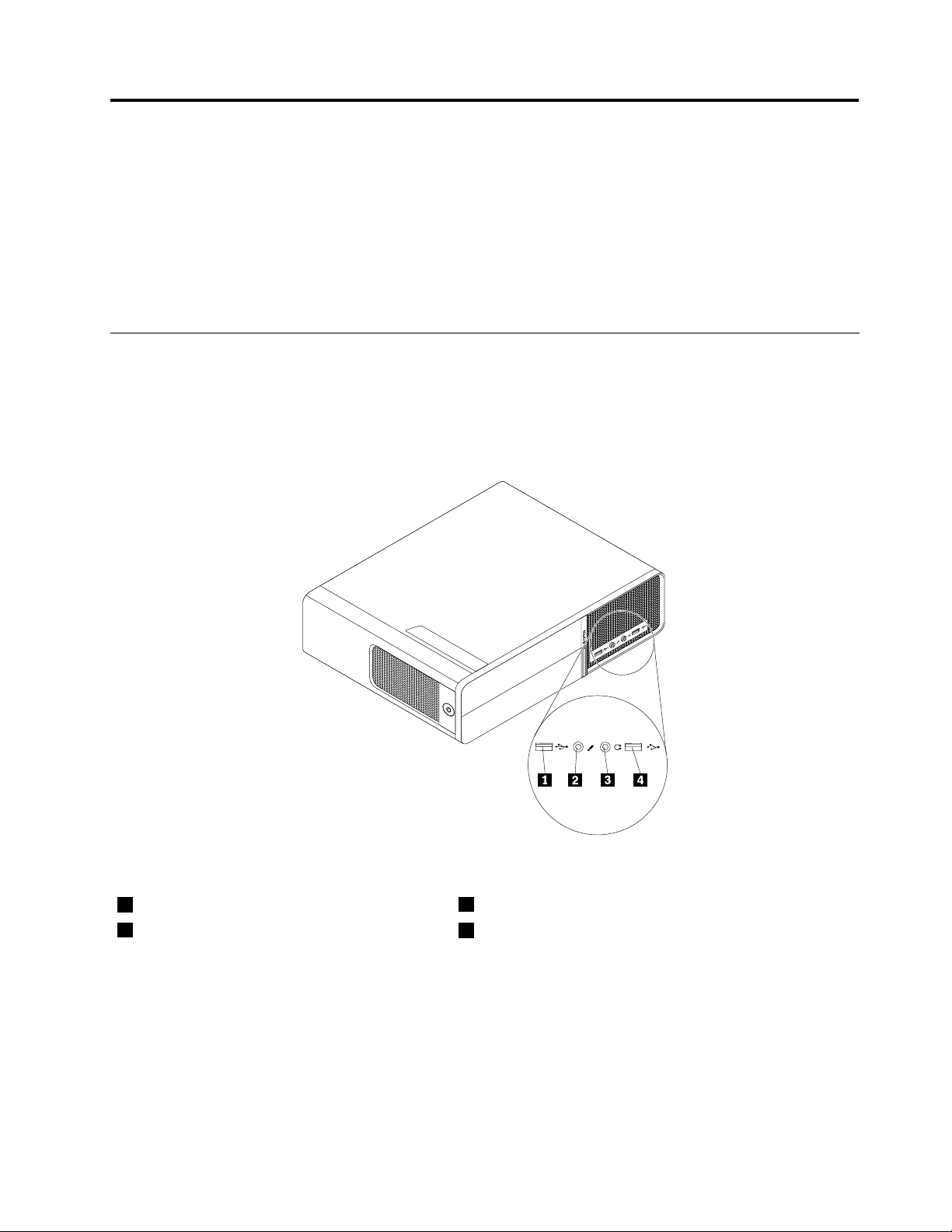
Chapter8.ReplacingFRUs
Thischapterprovidesstep-by-stepinstructionsforreplacingmajorFRUs.
Important
1.BesuretoreadandunderstandtheChapter2“Safetyinformation”onpage3beforereplacinganyFRU.
Theseprecautionsandguidelineswillhelpyouworksafely.
2.Thereplacementproceduresinthismanualareintendedtobedoneonlybytrainedservicetechnicians.
Locations
Locatingconnectorsonthefrontofyourcomputer
Frontconnectorlocationsshowsthelocationsoftheconnectorsonthefrontofyourcomputer.
Figure1.Frontconnectorlocations
1USBconnector
2Microphoneconnector
3Headphoneconnector
4USBconnector
Locatingconnectorsontherearofyourcomputer
Rearconnectorlocationsshowsthelocationsoftheconnectorsontherearofyourcomputer.Some
connectorsontherearofyourcomputerarecolor-codedtohelpyoudeterminewheretoconnectthe
cablesonyourcomputer.
©CopyrightLenovo2009,2010
65
Page 72
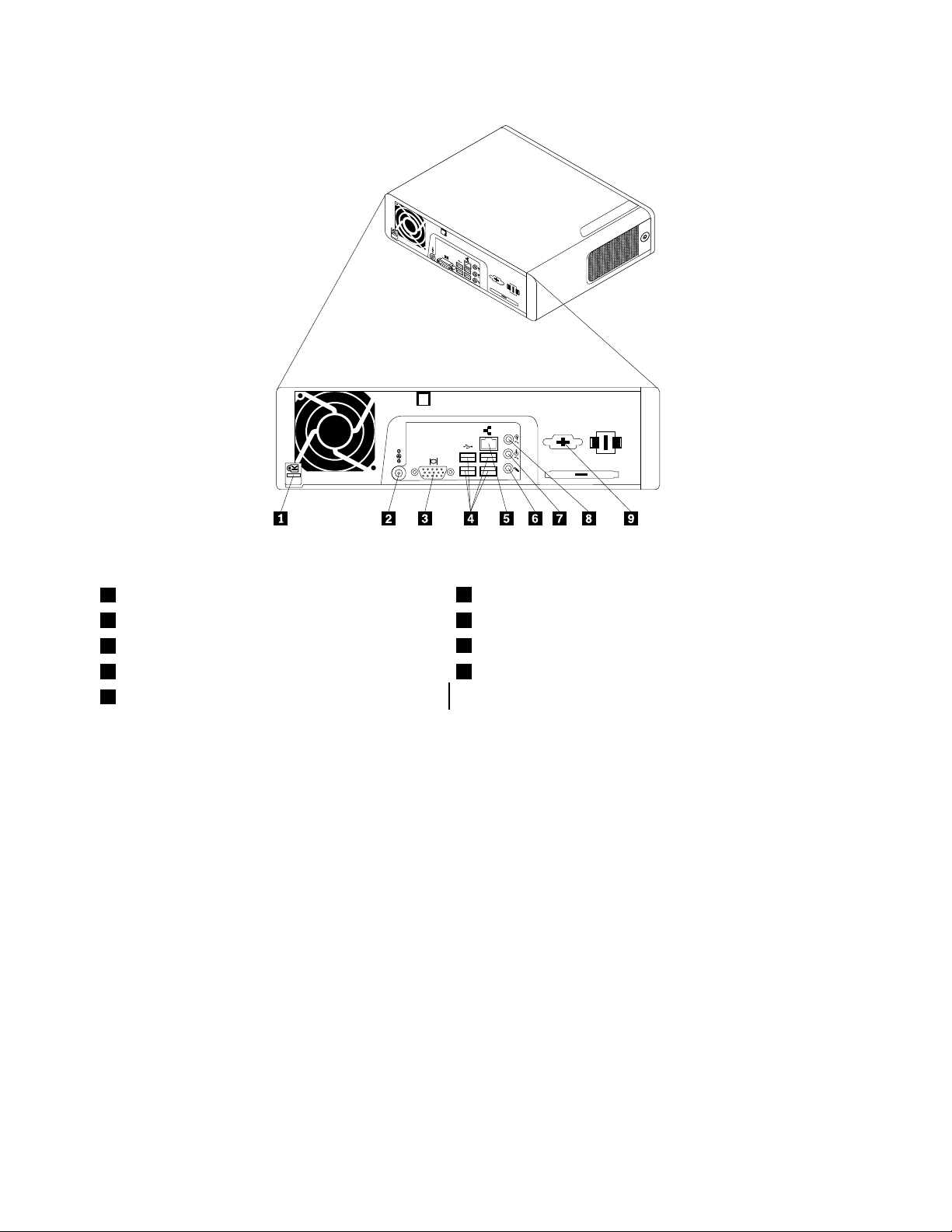
Figure2.Rearconnectorlocations
1Cablelocklatch
2acpoweradapterconnector7Audioline-outconnector
3VGAmonitorconnector
4USBconnectors(4)9Serialport(somemodels)
5Ethernetconnector
6Microphoneconnector
8Audioline-inconnector
Locatingcomponents
Figure3“Componentlocations”onpage67showsthelocationsofthevariouscomponentsinyour
computer.T oremovethecomputercover,see“Removingthecomputercover”onpage68.
66HardwareMaintenanceManual
Page 73
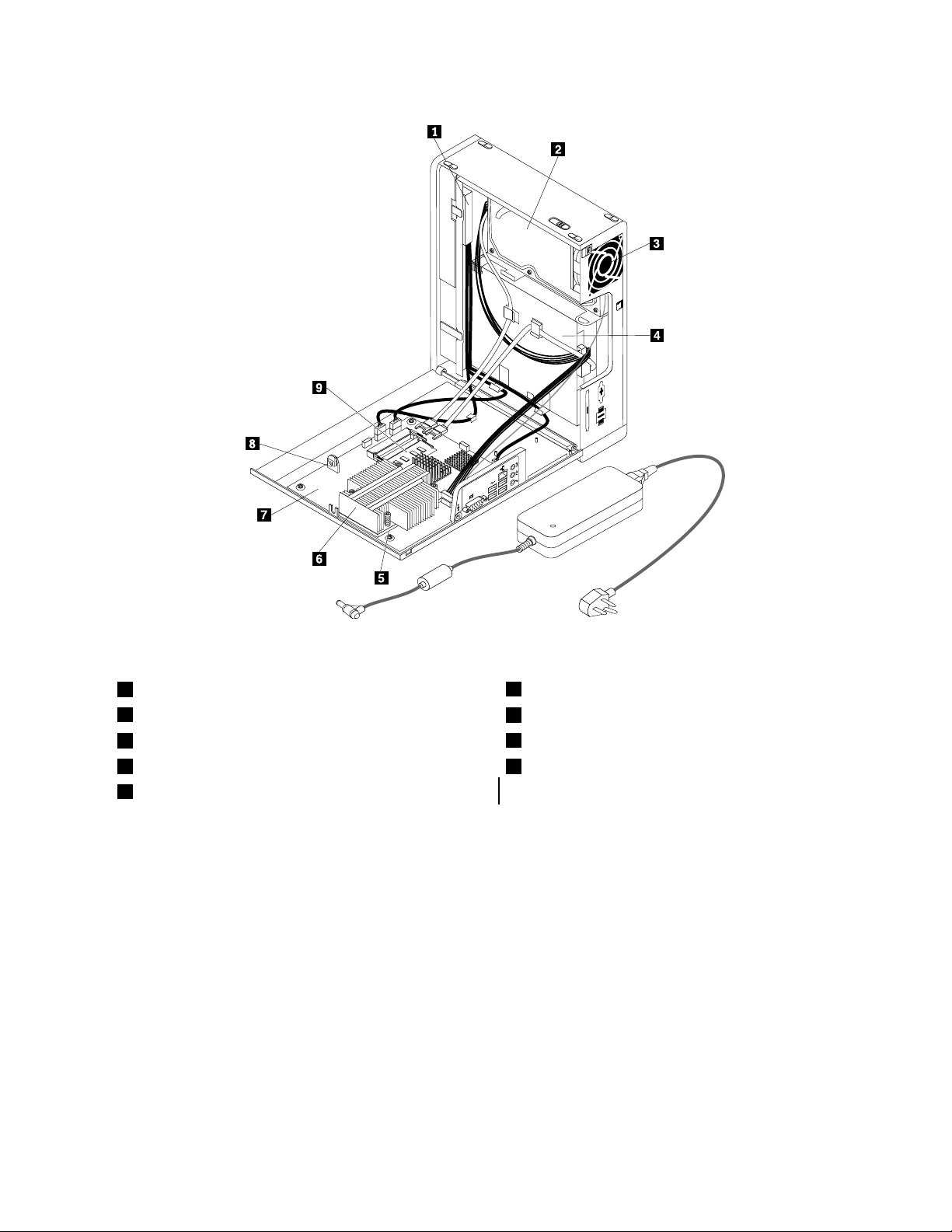
Figure3.Componentlocations
1FrontaudioandUSBassembly
2Harddiskdrive
3Systemfanassembly
4Opticaldrive9Memorymodules(2)
5Microprocessor
6Heatsink
7Systemboard
8Battery
Locatingpartsonthesystemboard
Figure4“Systemboardpartlocations”onpage68showsthelocationsofthepartsonthesystemboard.
Chapter8.ReplacingFRUs67
Page 74
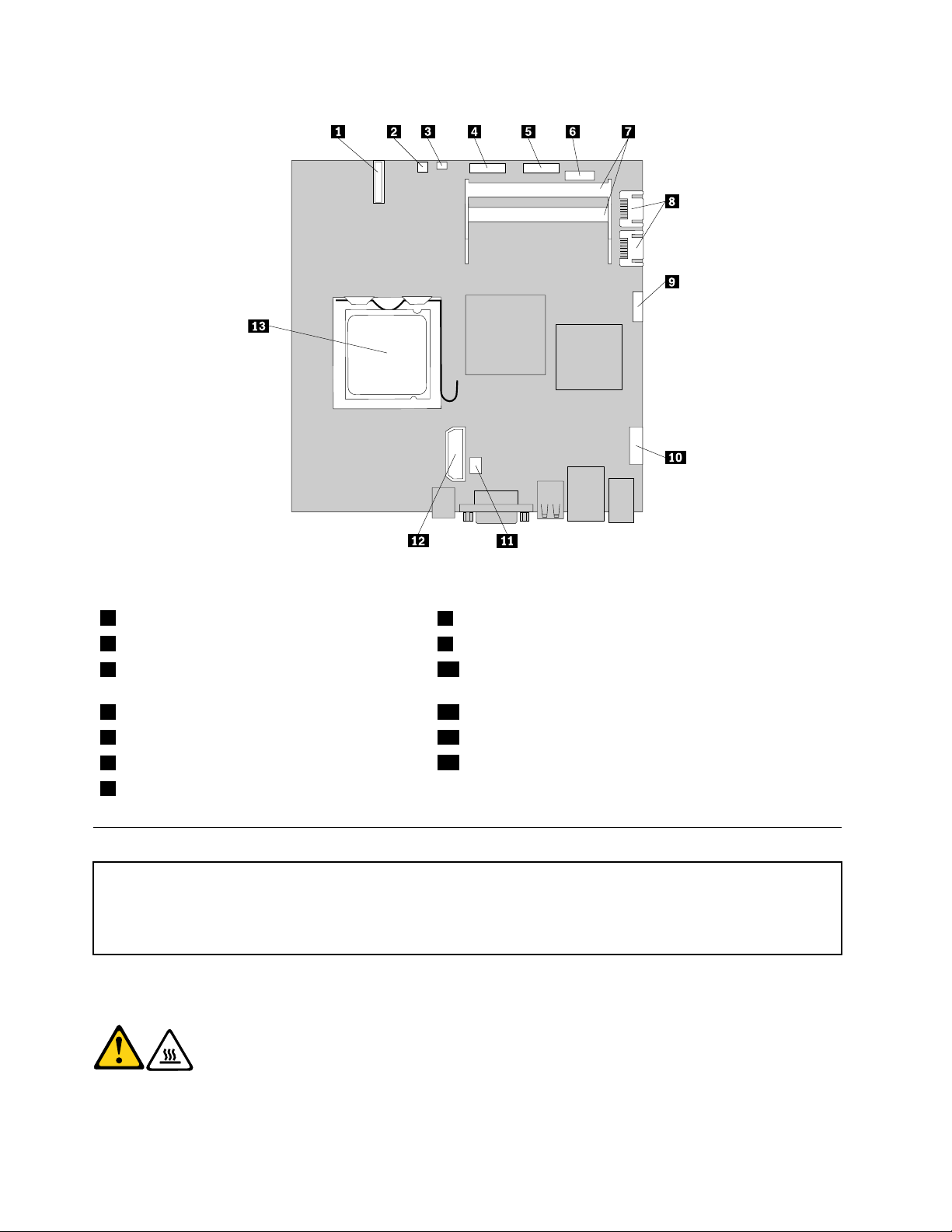
Figure4.Systemboardpartlocations
1Battery
2Thermalsensorconnector
3ClearCMOS(ComplementaryMetalOxide
8SATAconnectors(2)
9FrontUSBconnector2
10Frontaudioconnector
Semiconductor)/Recoveryjumper
4Serial(COM)connector11Systemfanconnector
5Frontpanelconnector12Internalpowerdistributionconnector
6FrontUSBconnector1
7Memoryslots(2)
13Microprocessor
Removingthecomputercover
Attention
Donotopenyourcomputerorattemptanyrepairbeforereadingandunderstandingthe“Importantsafetyinformation”
intheThinkCentreSafetyandWarrantyGuidethatcamewithyourcomputer.ToobtainacopyoftheThinkCentre
SafetyandWarrantyGuide,goto:http://www.lenovo.com/support
Thissectionprovidesinstructionsonhowtoremovethecomputercover.
CAUTION:
Turnoffthecomputerandwaitthreetoveminutestoletthecomputercoolbefore
removingthecomputercover.
Toremovethecomputercover,dothefollowing:
68HardwareMaintenanceManual
Page 75
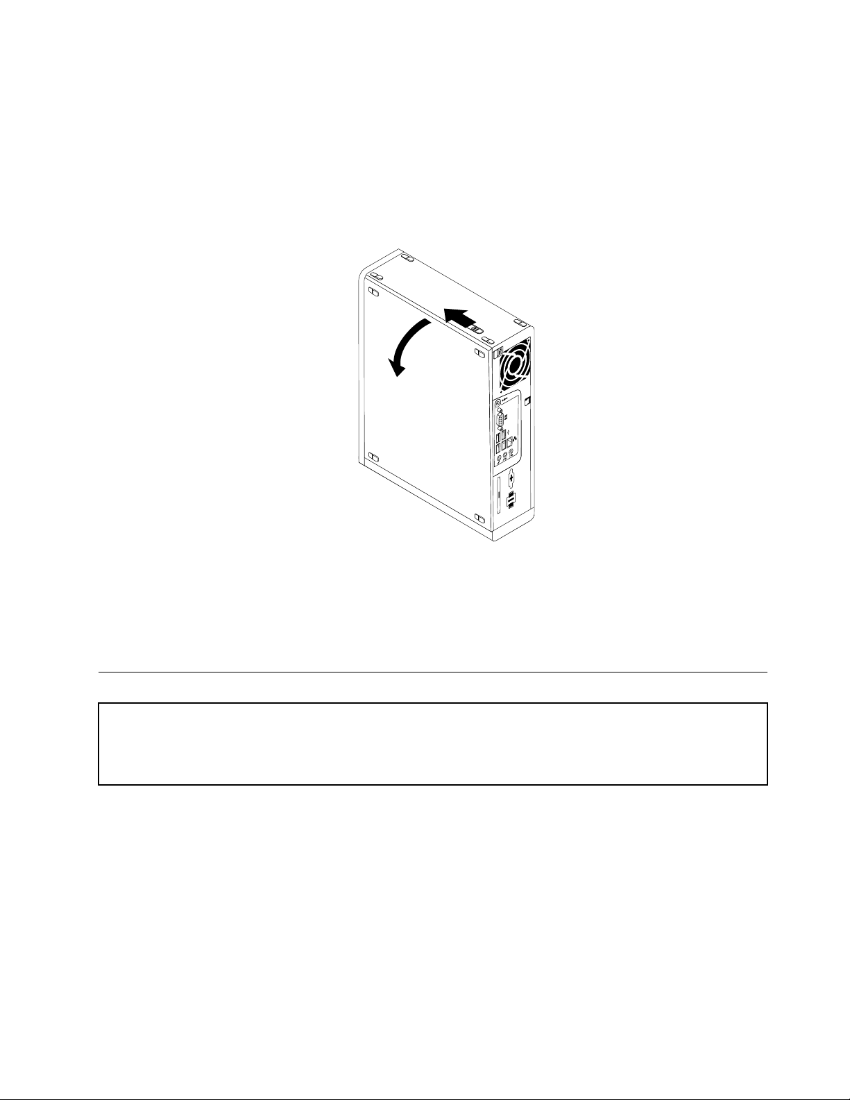
1.Removeanymediafromthedrives.Then,turnoffallattacheddevicesandthecomputer.
2.Disconnectallpowercordsfromelectricaloutlets.
3.Disconnectthepowercords,Input/Output(I/O)cables,andanyothercablesthatareconnectedtothe
computer.
4.Removeanylockingdevices,suchasacablelockthatsecuresthecomputercover.
5.Pushthecover-releasebuttononthesideofthecomputerandpivotthecomputercoveroutward.
Figure5.Removingthecomputercover
6.Notethelocationsofallpartsandconnectorsonthesystemboard.See“Locatingpartsonthe
systemboard”onpage67.
7.Disconnectallthecablesfromthesystemboardandcompletelyremovethecomputercover.
Removingandreinstallingthefrontbezel
Attention
Donotopenyourcomputerorattemptanyrepairbeforereadingandunderstandingthe“Importantsafetyinformation”
intheThinkCentreSafetyandWarrantyGuidethatcamewithyourcomputer.ToobtainacopyoftheThinkCentre
SafetyandWarrantyGuide,goto:http://www.lenovo.com/support
Thissectionprovidesinstructionsonhowtoremoveandreinstallthefrontbezel.
Toremoveandreinstallthefrontbezel,dothefollowing:
1.Removethecomputercover.See“Removingthecomputercover”onpage68.
2.Removethefrontbezelbyreleasingthetwoplastictabsandpivotingthefrontbezelforwardto
completelyremoveitfromthecomputer.
Chapter8.ReplacingFRUs69
Page 76
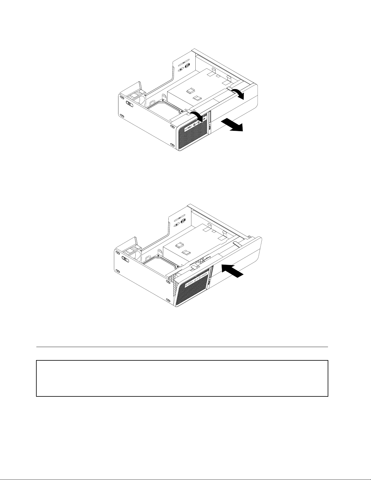
Figure6.Removingthefrontbezel
3.T oreinstallthefrontbezel,aligntheholesinthebottomofthefrontbezelwiththecorrespondingplastic
tabsonthechassis.Then,pivotthefrontbezelinwarduntilitsnapsintoposition.
Figure7.Reinstallingthefrontbezel
4.Goto“Completingthepartsreplacement”onpage84.
Installingorreplacingamemorymodule
Attention
Donotopenyourcomputerorattemptanyrepairbeforereadingandunderstandingthe“Importantsafetyinformation”
intheThinkCentreSafetyandWarrantyGuidethatcamewithyourcomputer.ToobtainacopyoftheThinkCentre
SafetyandWarrantyGuide,goto:http://www.lenovo.com/support
Thissectionprovidesinstructionsonhowtoinstallorreplaceamemorymodule.
Yourcomputerhastwomemoryslotsforinstallingorreplacing1GBDDR2SODIMMsthatprovideuptoa
maximumof2GBofsystemmemory.
70HardwareMaintenanceManual
Page 77
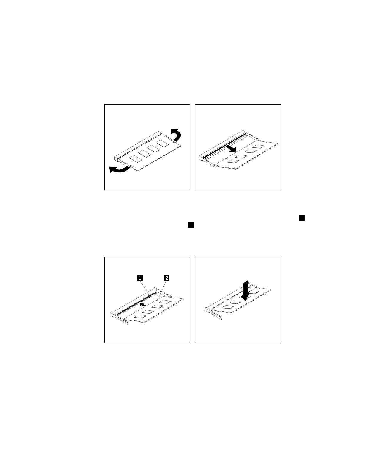
Toinstallorreplaceamemorymodule,dothefollowing:
1.Removethecomputercover.See“Removingthecomputercover”onpage68.
2.Locatethememoryslotsonthesystemboard.See“Locatingpartsonthesystemboard”onpage67.
3.Ifyouarereplacingamemorymodule,opentheretainingclipsoftheappropriatememoryslotand
removetheoldmemorymodulethatiscurrentlyinstalled.Ifyouareinstallingamemorymodule,go
tostep4.
Figure8.Removingthememorymodule
4.Insertthenewmemorymoduleintotheappropriatememoryslot.Makesurethatthenotch2ofthe
newmemorymodulearealignedwiththeslotkey1ofthememoryslot.Then,pressthenewmemory
modulermlyandpivotitdownuntilitsnapsintoposition.Makesurethatthenewmemorymoduleis
rmlyinstalledinthememoryslotanddoesnotmoveeasily.
Figure9.Installingthememorymodule
Whattodonext:
•T oworkwithanotherpieceofhardware,gototheappropriatesection.
•T ocompletetheinstallationorreplacement,goto“Completingthepartsreplacement”onpage84.
Chapter8.ReplacingFRUs71
Page 78
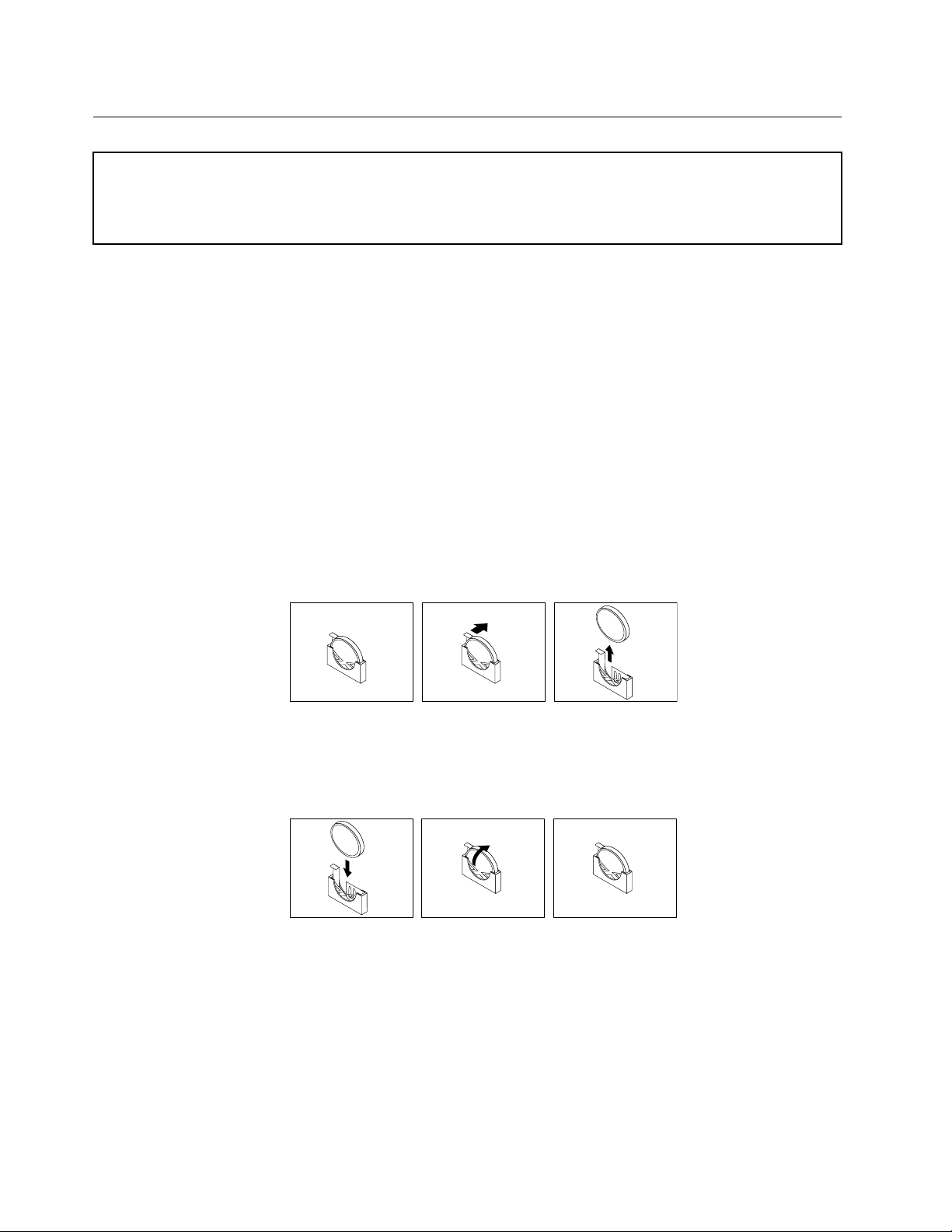
Replacingthebattery
Attention
Donotopenyourcomputerorattemptanyrepairbeforereadingandunderstandingthe“Importantsafetyinformation”
intheThinkCentreSafetyandWarrantyGuidethatcamewithyourcomputer.ToobtainacopyoftheThinkCentre
SafetyandWarrantyGuide,goto:http://www.lenovo.com/support
Yourcomputerhasaspecialtypeofmemorythatmaintainsthedate,time,andcongurationinformationfor
built-infeatures.Thebatterykeepstheseinformationactivewhenyouturnoffthecomputer.
Thebatterynormallyrequiresnochargingormaintenancethroughoutitslife,however,nobatterylasts
forever.Ifthebatteryfails,thedate,time,andcongurationinformation(includingpasswords)arelost.An
errormessageisdisplayedwhenyouturnonthecomputer.
Beforeperformingthefollowingprocedure,besuretoreadandunderstandtheinformationaboutreplacing
anddisposingofthebatteryinthe“Lithiumbatterynotice”sectionoftheThinkCentreSafetyandWarranty
Guide.
Toreplacethebattery,dothefollowing:
1.Removethecomputercover.See“Removingthecomputercover”onpage68.
2.Locatethebatteryonthesystemboard.See“Locatingcomponents”onpage66.
3.Removetheoldbattery.
Figure10.Removingthebattery
4.Installthenewbattery.
Figure11.Installingthebattery
5.Reinstallthecomputercoverandreconnectthecables.See“Completingthepartsreplacement”
onpage84.
6.T urnonthecomputerandallattacheddevices.
Note:Whenthecomputeristurnedonforthersttimeafterreplacingthebattery,anerrormessage
mightbedisplayed.Thisisnormalafterreplacingthebattery.
72HardwareMaintenanceManual
Page 79
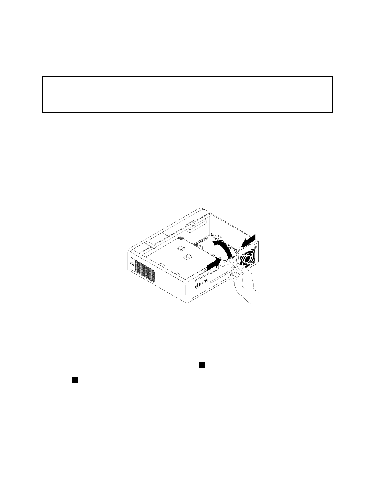
7.UsetheSetupUtilityprogramtosetthedate,time,andanypasswords.SeeChapter6“Usingthe
SetupUtility”onpage41.
Replacingtheharddiskdrive
Attention
Donotopenyourcomputerorattemptanyrepairbeforereadingandunderstandingthe“Importantsafetyinformation”
intheThinkCentreSafetyandWarrantyGuidethatcamewithyourcomputer.ToobtainacopyoftheThinkCentre
SafetyandWarrantyGuide,goto:http://www.lenovo.com/support
Thissectionprovidesinstructionsonhowtoreplacetheharddiskdrive.
Toreplacetheharddiskdrive,dothefollowing:
1.Removethecomputercover.See“Removingthecomputercover”onpage68.
2.Thepowercableconnectedtotheopticaldrivemightpreventyoufromreplacingtheharddiskdrive.
Disconnectthepowercablefromtheopticaldriverst.
3.Placeyourngeronthetablocatedonthefrontoftheharddiskdriveandpushupward.Meanwhile,
pressinwardonthesidetabsofthebracketandpivottheharddiskdriveupwardtoremoveitfrom
theharddiskdrivebay.
Figure12.Removingtheharddiskdrive
4.Disconnectthesignalcableandthepowercablefromtherearoftheoldharddiskdrivetocompletely
removeitfromthecomputer.
5.Flexthesidesoftheplasticbracketproperlysothattheharddiskdrivecanberemovedoutofthe
bracket.
6.Installthenewharddiskdriveintotheplasticbracket1byexingthebracketproperlyandaligning
thepinsonthebracketwiththecorrespondingholesontheharddiskdrive.Donottouchthecircuit
board
2onthebottomoftheharddiskdrive.
Chapter8.ReplacingFRUs73
Page 80
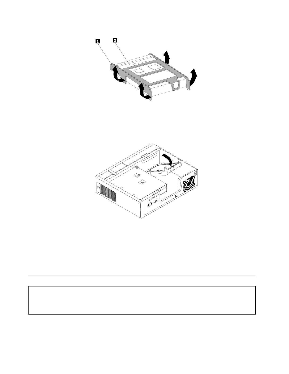
Figure13.Installingtheharddiskdriveintothebracket
7.Connectthesignalcableandthepowercabletotherearofthenewharddiskdrive.
8.Slidethenewharddiskdriveintotheharddiskdrivebayandpivotitdownuntilitsnapsintoposition.
Figure14.Installingtheharddiskdrive
9.Reconnectthepowercabletotheopticaldrive.
Whattodonext:
•T oworkwithanotherpieceofhardware,gototheappropriatesection.
•T ocompletethereplacement,goto“Completingthepartsreplacement”onpage84.
Replacingtheopticaldrive
Attention
Donotopenyourcomputerorattemptanyrepairbeforereadingandunderstandingthe“Importantsafetyinformation”
intheThinkCentreSafetyandWarrantyGuidethatcamewithyourcomputer.ToobtainacopyoftheThinkCentre
SafetyandWarrantyGuide,goto:http://www.lenovo.com/support
Thissectionprovidesinstructionsonhowtoreplacetheopticaldrive.
Toreplacetheopticaldrive,dothefollowing:
74HardwareMaintenanceManual
Page 81
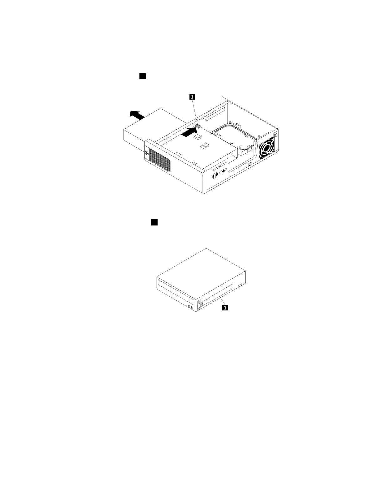
1.Removethecomputercover.See“Removingthecomputercover”onpage68.
2.Removethefrontbezel.See“Removingandreinstallingthefrontbezel”onpage69.
3.Disconnectthesignalcableandthepowercablefromtherearoftheopticaldrive.
4.Pressthebluereleasebutton1andslidetheopticaldriveoutthefrontofthecomputer.
Figure15.Removingtheopticaldrive
5.Removetheopticaldriveretainer1fromtheoldopticaldriveandinstallitonthesideofthenew
opticaldrive.
Figure16.Installingtheretainerontheopticaldrive
6.Slidethenewopticaldriveintothedrivebayuntilitsnapsintoposition.
Chapter8.ReplacingFRUs75
Page 82
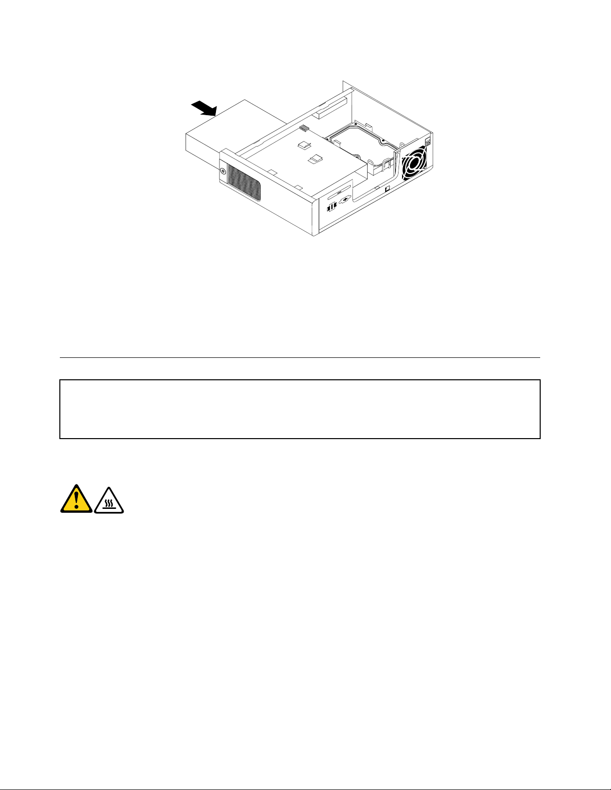
Figure17.Installingtheopticaldrive
7.Connectthesignalcableandthepowercabletotherearofthenewopticaldrive.
Whattodonext:
•T oworkwithanotherpieceofhardware,gototheappropriatesection.
•T ocompletethereplacement,goto“Completingthepartsreplacement”onpage84.
Replacingtheheatsink
Attention
Donotopenyourcomputerorattemptanyrepairbeforereadingandunderstandingthe“Importantsafetyinformation”
intheThinkCentreSafetyandWarrantyGuidethatcamewithyourcomputer.ToobtainacopyoftheThinkCentre
SafetyandWarrantyGuide,goto:http://www.lenovo.com/support
Thissectionprovidesinstructionsonhowtoreplacetheheatsink.
CAUTION:
Theheatsinkmightbeveryhot.Turnoffthecomputerandwaitthreetoveminutesto
letthecomputercoolbeforeremovingthecomputercover.
Toreplacetheheatsink,dothefollowing:
1.Removethecomputercover.See“Removingthecomputercover”onpage68.
2.Locatetheheatsink.See“Locatingcomponents”onpage66.
3.Removethefourscrewsthatsecuretheheatsink.Then,lifttheheatsinkoffthesystemboard.
Notes:
a.Carefullyremovethefourscrewsfromthesystemboardtoavoidanypossibledamage.Thefour
screwscannotberemovedfromtheheatsink.
b.Youmighthavetogentlytwisttheheatsinktofreeitfromthemicroprocessor.
c.Whenhandlingtheheatsink,donottouchthethermalgreaseonthebottomoftheheatsink.
76HardwareMaintenanceManual
Page 83
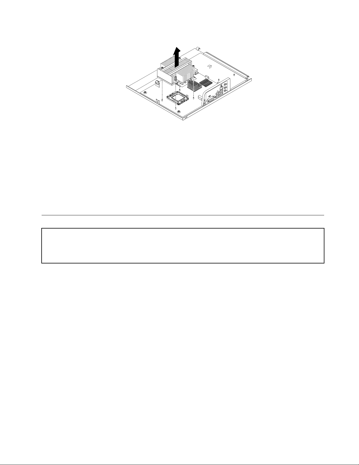
Figure18.Removingtheheatsink
4.Placethenewheatsinkonthesystemboardsothatthefourscrewsarealignedwiththefour
correspondingmountingstudsonthesystemboard.
5.Alternatetighteningeachscrewasmallandequalamountuntiltheheatsinkissecuredtothesystem
board.Donotover-tightenthescrews.
Whattodonext:
•T oworkwithanotherpieceofhardware,gototheappropriatesection.
•T ocompletethereplacement,goto“Completingthepartsreplacement”onpage84.
Replacingthesystemfanassembly
Attention
Donotopenyourcomputerorattemptanyrepairbeforereadingandunderstandingthe“Importantsafetyinformation”
intheThinkCentreSafetyandWarrantyGuidethatcamewithyourcomputer.ToobtainacopyoftheThinkCentre
SafetyandWarrantyGuide,goto:http://www.lenovo.com/support
Thissectionprovidesinstructionsonhowtoreplacethesystemfanassembly.
Toreplacethesystemfanassembly,dothefollowing:
1.Removethecomputercover.See“Removingthecomputercover”onpage68.
2.Disconnectthesystemfanassemblycablefromthesystemfanconnectoronthesystemboard.See
“Locatingpartsonthesystemboard”onpage67.
3.Y oumighthavetoremovetheharddiskdrivetogainaccesstothesystemfanassembly.See
“Replacingtheharddiskdrive”onpage73.
4.Breakorcuttherubbermountsthatsecurethesystemfanassemblytothechassis.Then,remove
thesystemfanassemblyoutofthecomputer.
Chapter8.ReplacingFRUs77
Page 84
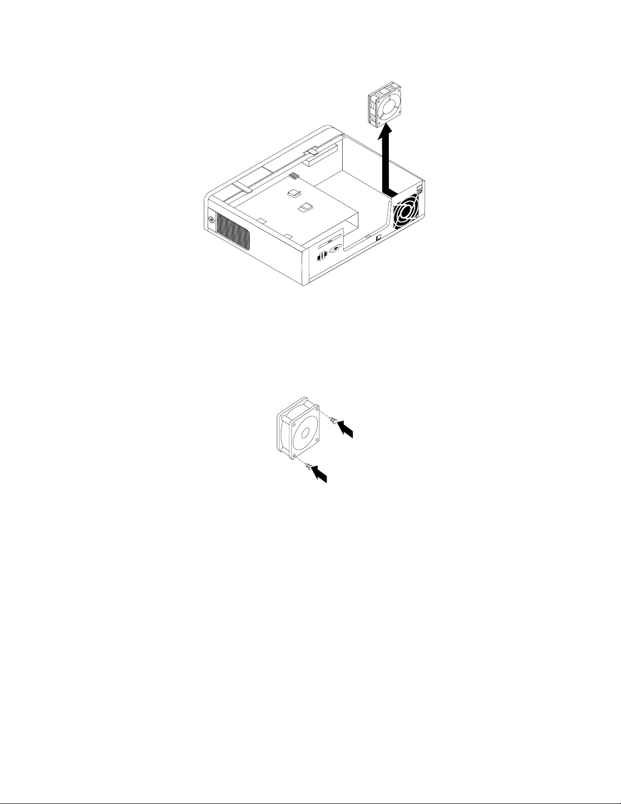
Figure19.Removingthesystemfanassembly
5.Installthetwonewshortrubbermountstothenewsystemfanassembly.
Note:Thenewsystemfanassemblycomestogetherwithfournewrubbermounts:twoshortrubber
mountsandtwolongrubbermounts.
Figure20.Installingtheshortrubbermounts
6.Installthetwonewlongrubbermountsbypushingthemthroughtheholesontherearofthechassis.If
necessary,pulltherubbermountsthroughtheholesfromtheinsideofthechassistomakesurethatthe
rubbermountsareinstalledinplace.
7.T oinstallthenewsystemfanassemblyintothechassis,aligntheholesonthenewsystemfanassembly
withthelongrubbermountsinthechassis.Then,pushorpulltherubbermountsthroughtheholesuntil
thenewsystemfanassemblyissecuredinplace.
78HardwareMaintenanceManual
Page 85
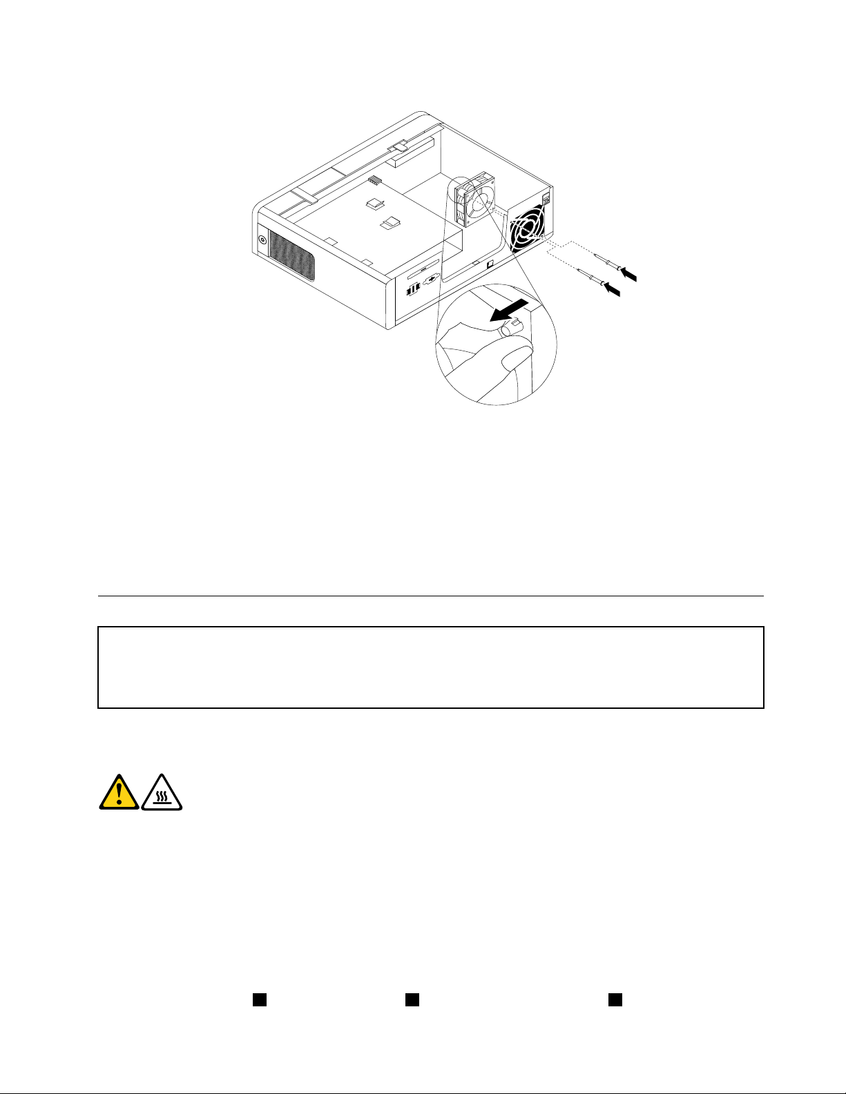
Figure21.Installingthesystemfanassembly
8.Connectthecableofthenewsystemfanassemblytothesystemfanconnectoronthesystemboard.
9.Reinstalltheharddiskdriveifyouhaveremovedit.
Whattodonext:
•T oworkwithanotherpieceofhardware,gototheappropriatesection.
•T ocompletethereplacement,goto“Completingthepartsreplacement”onpage84.
Replacingthemicroprocessor
Attention
Donotopenyourcomputerorattemptanyrepairbeforereadingandunderstandingthe“Importantsafetyinformation”
intheThinkCentreSafetyandWarrantyGuidethatcamewithyourcomputer.ToobtainacopyoftheThinkCentre
SafetyandWarrantyGuide,goto:http://www.lenovo.com/support
Thissectionprovidesinstructionsonhowtoreplacethemicroprocessor.
CAUTION:
Theheatsinkandmicroprocessormightbeveryhot.Turnoffthecomputerandwait
threetoveminutestoletthecomputercoolbeforeremovingthecomputercover.
Toreplacethemicroprocessor,dothefollowing:
1.Removethecomputercover.See“Removingthecomputercover”onpage68.
2.Removeanypartsanddisconnectanycablesthatmightpreventyouraccesstothesystemboard.
3.Locatetheheatsinkandremoveitfromthesystemboard.See“Locatingcomponents”onpage
66and“Replacingtheheatsink”onpage76.
4.Placetheheatsinkonitssidesothatthethermalgreaseonthebottomoftheheatsinkdoesnot
getincontactwithanything.
5.Liftthesmallhandle1andopentheretainer3toaccessthemicroprocessor2.
Chapter8.ReplacingFRUs79
Page 86
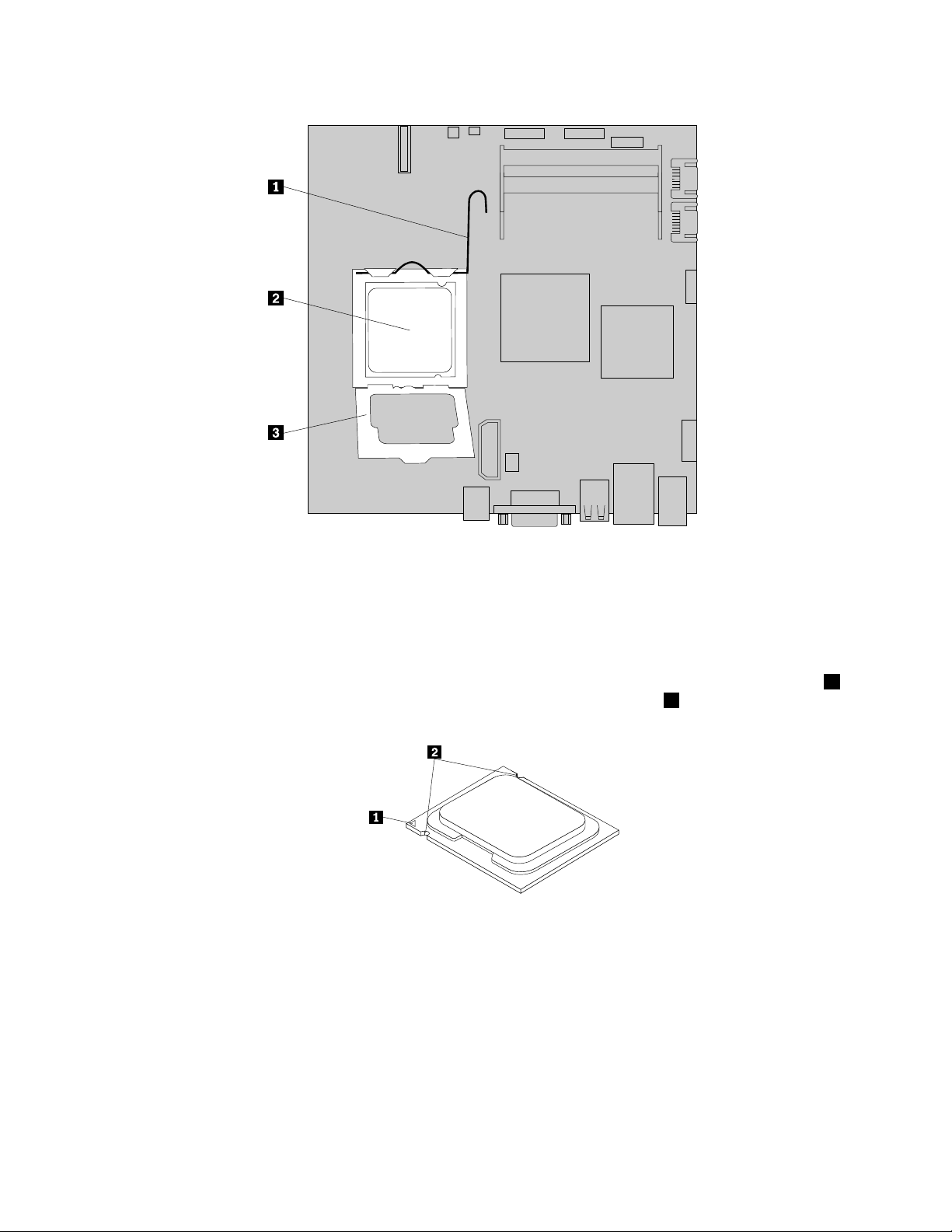
Figure22.Accessingthemicroprocessor
6.Liftthemicroprocessorstraightupandoutofthemicroprocessorsocket.
Notes:
a.Yourmicroprocessorandsocketmightlookdifferentfromtheoneillustrated.
b.Notetheorientationofthemicroprocessorinthesocket.Youcaneitherlookforthesmalltriangle1
ononecornerofthemicroprocessorornotetheorientationofthenotches2onthemicroprocessor.
Thisisimportantwheninstallingthenewmicroprocessoronthesystemboard.
c.Touchonlythesidesofthemicroprocessor.Donottouchthegoldcontactsonthebottom.
d.Donotdropanythingontothemicroprocessorsocketwhileitisexposed.Thesocketpinsmustbe
keptascleanaspossible.
80HardwareMaintenanceManual
Page 87
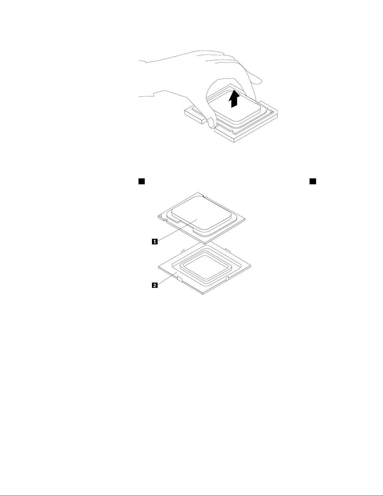
Figure23.Removingthemicroprocessor
7.Makesurethatthesmallhandleisintheraisedpositionandthemicroprocessorretainerisopen.
8.Removetheprotectivecover2thatprotectsthegoldcontactsofthenewmicroprocessor1.
9.Holdthenewmicroprocessorandalignthenotchesonitwiththetabsinthemicroprocessorsocket,
oralignthesmalltriangleononecornerofthenewmicroprocessorwiththecorrespondingbeveled
cornerofthemicroprocessorsocket.
10.Lowerthenewmicroprocessorstraightdownintothemicroprocessorsocketonthesystemboard.
11.Closethemicroprocessorretainerandlockitintopositionwiththesmallhandletosecurethenew
microprocessorinthesocket.
12.Reinstalltheheatsinkonthesystemboard.See“Replacingtheheatsink”onpage76.
13.Reinstallanyotherpartsandreconnectanyothercablesyouremoved.
Whattodonext:
•T oworkwithanotherpieceofhardware,gototheappropriatesection.
•T ocompletethereplacement,goto“Completingthepartsreplacement”onpage84.
Chapter8.ReplacingFRUs81
Page 88
Replacingthesystemboard
Attention
Donotopenyourcomputerorattemptanyrepairbeforereadingandunderstandingthe“Importantsafetyinformation”
intheThinkCentreSafetyandWarrantyGuidethatcamewithyourcomputer.ToobtainacopyoftheThinkCentre
SafetyandWarrantyGuide,goto:http://www.lenovo.com/support
Thissectionprovidesinstructionsonhowtoreplacethesystemboard.
CAUTION:
Theheatsinkandmicroprocessormightbeveryhot.Turnoffthecomputerandwait
threetoveminutestoletthecomputercoolbeforeremovingthecomputercover.
Toreplacethesystemboard,dothefollowing:
1.Removethecomputercover.See“Removingthecomputercover”onpage68.
2.T akenotesofthelocationsofallpartsandallcableconnectorsonthesystemboard.See“Locating
components”onpage66and“Locatingpartsonthesystemboard”onpage67.Then,disconnectall
thecables.
3.Removethememorymodulesfromtheoldsystemboard.See“Installingorreplacingamemory
module”onpage70
4.Removethebatteryfromtheoldsystemboard.See“Replacingthebattery”onpage72.
5.Removetheheatsinkfromtheoldsystemboard.See“Replacingtheheatsink”onpage76.
6.Removethemicroprocessorfromtheoldsystemboard.See“Replacingthemicroprocessor”onpage
.
79
7.Removethescrewsthatsecuretheoldsystemboard.Then,carefullyremovetheoldsystemboard
outofthechassis.
8.Placetheoldsystemboardonacleanandatsurface.
9.Positionthenewsystemboardsothatthescrewholesarealignedwiththemountingstudsonthe
computercover.
10.Installthescrewstosecurethenewsystemboardinplace.
11.Installthememorymodules,battery,microprocessor,andheatsinkthatyouremovedfromtheold
systemboardtothenewsystemboard.
12.Connectallthecablestothenewsystemboard.See“Locatingpartsonthesystemboard”onpage67.
.
Whattodonext:
•T oworkwithanotherpieceofhardware,gototheappropriatesection.
•T ocompletethereplacement,goto“Completingthepartsreplacement”onpage84
Thefailingsystemboardmustbereturnedwithamicroprocessorsocketcovertoprotectthepinsduring
shippingandhandling.
Toinstallthemicroprocessorsocketcover,dothefollowing:
1.Removethemicroprocessorfromthemicroprocessorsocket.See“Replacingthemicroprocessor”
onpage79.
2.Closethemicroprocessorretainerandlockitintopositionwiththesmallhandle.
82HardwareMaintenanceManual
.
Page 89
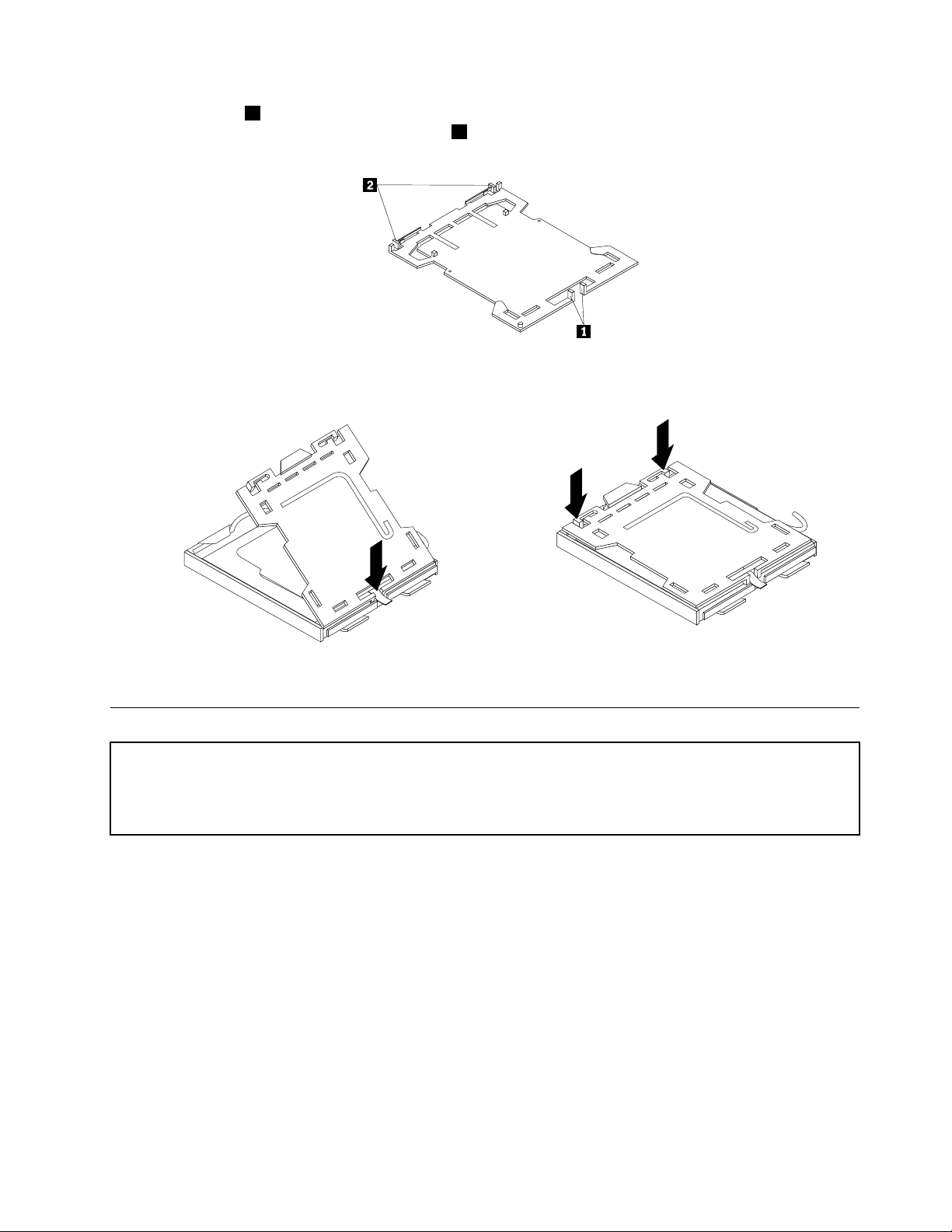
3.Insertthetabs1ofthesocketcoverintothehingedsideofthesocket,andthenpresstheotherside
ofthesocketcoverdownwarduntilthetabs2snapintoposition.
Figure24.T absonthemicroprocessorsocketcover(bottomview)
Figure25.Installingthemicroprocessorsocketcover
Replacingtheacpoweradapter
Attention
Donotopenyourcomputerorattemptanyrepairbeforereadingandunderstandingthe“Importantsafetyinformation”
intheThinkCentreSafetyandWarrantyGuidethatcamewithyourcomputer.ToobtainacopyoftheThinkCentre
SafetyandWarrantyGuide,goto:http://www.lenovo.com/support
Thissectionprovidesinstructionsonhowtoreplacetheacpoweradapter.
Toreplacetheacpoweradapter,dothefollowing:
1.Removeanymediafromthedrives.Then,turnoffallattacheddevicesandthecomputer.
2.Disconnecttheacpoweradaptercordfromtheelectricaloutlet.
3.Locatetheacpoweradapterconnectorontherearofthecomputer.See“Locatingconnectorsonthe
rearofyourcomputer”onpage65.
4.Disconnecttheacpoweradaptercablefromtheacpoweradapterconnector.
5.Connectthecableofthenewacpoweradaptertotheacpoweradapterconnectorontherearofthe
computerandtotheelectricaloutlet.
Chapter8.ReplacingFRUs83
Page 90
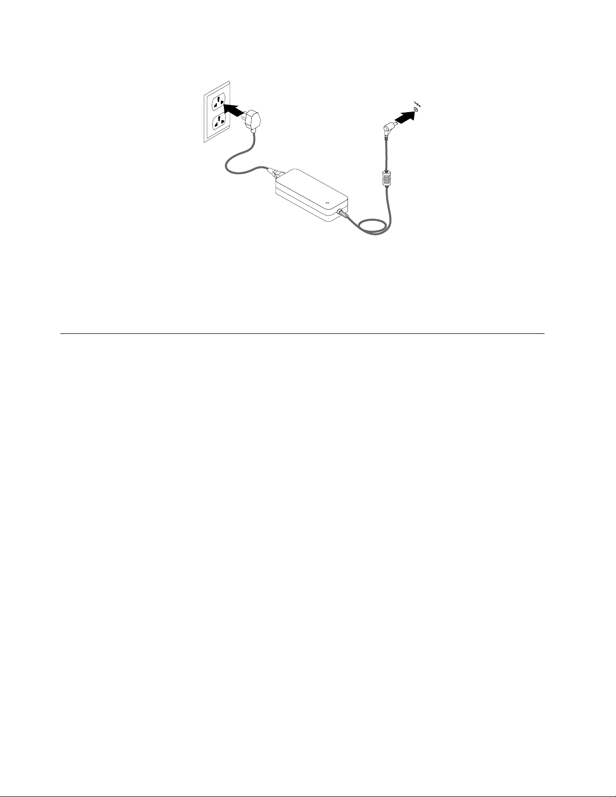
Figure26.Connectingtheacpoweradapter
Whattodonext:
•T oworkwithanotherpieceofhardware,gototheappropriatesection.
•T ocompletethereplacement,goto“Completingthepartsreplacement”onpage84
.
Completingthepartsreplacement
Thissectionprovidesinstructionsonhowtocompletethepartsreplacement.
Aftercompletingtheinstallationorreplacementforallparts,youneedtoreinstallthecomputercoverand
reconnectcables.Dependingonthepartsyouinstalledorreplaced,youmightneedtoconrmtheupdated
informationintheSetupUtilityprogram.RefertoChapter6“UsingtheSetupUtility”onpage41.
Toreinstallthecomputercoverandreconnectcablestoyourcomputer,dothefollowing:
1.Makesurethatallcomponentshavebeenreassembledcorrectlyandthatnotoolsorloosescrewsare
leftinsideyourcomputer.See“Locatingcomponents”onpage66
componentsinyourcomputer.
2.Ifyouhaveremovedthefrontbezel,reinstallit.See“Removingandreinstallingthefrontbezel”on
page69.
3.Makesurethatthecablesareroutedcorrectlybeforeclosingthecomputercover.Keepcablesclearof
thehingesandsidesofthecomputerchassistoavoidinterferencewithreinstallingthecomputercover.
forthelocationsofthevarious
84HardwareMaintenanceManual
Page 91
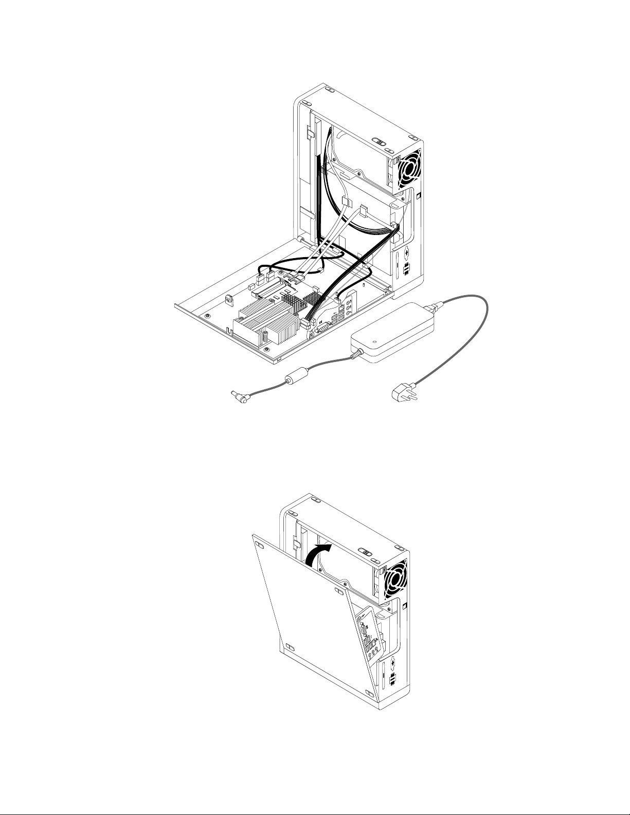
Figure27.Routingthecables
4.Positionthecomputercoveronthechassissothattherailguideonthecomputercoverengagestherail
onthechassis.Then,pivotthecomputercovercloseduntilitsnapsintoposition.
Figure28.Installingthecomputercover
Chapter8.ReplacingFRUs85
Page 92

5.Ifthereisacomputercablelockavailable,lockthecomputer.
6.Reconnecttheexternalcablesandpowercordstothecomputer.
7.T oupdateyourconguration,refertoChapter6“UsingtheSetupUtility”onpage41.
Note:Inmostareasoftheworld,LenovorequiresthereturnofthedefectiveCRUs.Informationaboutthis
willcomewiththeCRUsorwillcomeafewdaysafteryoureceivedtheCRUs.
86HardwareMaintenanceManual
Page 93
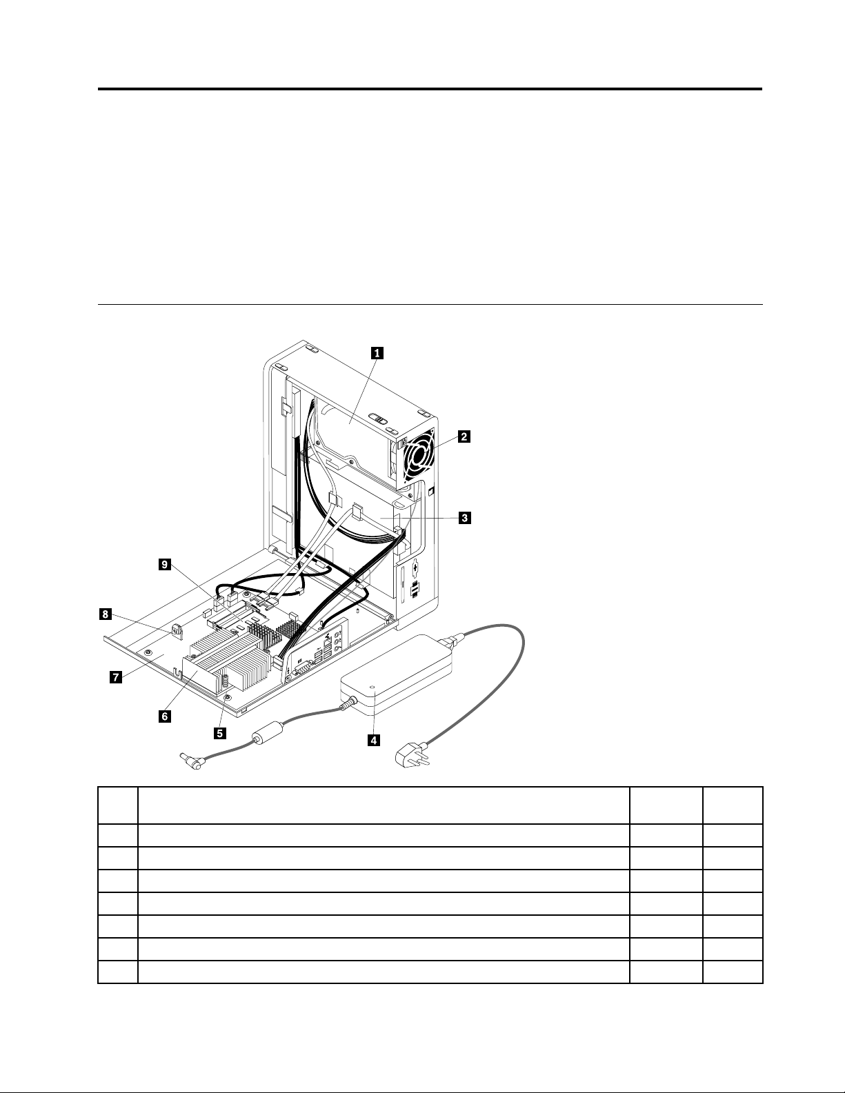
Chapter9.FRUlists
ThischapterliststheFRUinformation.
Attention:BesuretoreadandunderstandtheChapter2“Safetyinformation”onpage3andAppendixA
“Notices”onpage101beforereplacinganyFRUs.
Note:Inthefollowingtables,aCRUisidentiedas"1","2",or"N"intheCRUcolumn."N"meansthat
thepartisnotaCRU,"1"meansthatthepartisaSelf-serviceCRU,and"2"meansthatthepartisan
Optional-serviceCRU.
MachineType3425
Item
#3425FRUsFRU#CRU
1
Harddiskdrive,SA TA160GB7200RPM/3Gb/8M(modelsA1JA2JA5JA6JA9JB1J)
1
Harddiskdrive,SA TA160GB7200RPM/3Gb/8M(modelsA1JA2JA5JA6JA9JB1J)
1
Harddiskdrive,SAT A250GB7200RPM/3Gb/8M(modelsA3JA4JA7JA8J)
1
Harddiskdrive,SAT A250GB7200RPM/3Gb/8M(modelsA3JA4JA7JA8J)
1
Harddiskdrive,SATA320GB7200RPM/3Gb/8M(models)
1
Harddiskdrive,SATA320GB7200RPM/3Gb/8M(models)
1
Harddiskdrive,SATA500GB7200RPM/3Gb/16M(models)
©CopyrightLenovo2009,2010
40Y90351
53Y68371
40Y90361
45K04081
87H48911
45K04091
41X55821
87
Page 94
Item
#3425FRUsFRU#CRU
1
Harddiskdrive,SATA500GB7200RPM/3Gb/16M(models)
3
Opticaldrive,DVD-ROMDrive-16x/48x-SATA(modelsA1JA3JA5JA8JB1J)
3
Opticaldrive,DVD-ROMDrive-16x/48x-SATA(modelsA1JA3JA5JA8JB1J)
3
Opticaldrive,DVDRecordableRambo8-SATA12XRAMWrite(modelsA2JA4J
A6JA7JA9J)
3
Opticaldrive,DVDRecordableRambo8-SATA12XRAMWrite(modelsA2JA4J
A6JA7JA9J)
4
Powersupply,120Wac/dcpoweradapter(modelsA1JA2JA3JA4JA5JA6JA7J
A8JA9JB1J)
5
Microprocessor,NTELCDCE14002/512/775/45WM0CPU2.00GHz,800MHz,512K,
775QCJEM-0stepping45W(models)
5
Microprocessor,IntelPDCE52002.5/800/2/77545R0CPU2.50GHz,R-0Stepping,
65nm,800MHzFSB,2MBL2,45W(models)
5
Microprocessor,Intel450Processor2.2/800/512/775A12.20GHz,A-1Stepping,
65nm,800MHzFSB,512KBL2,35W(modelsA1JA2JA5JA6JA9JB1J)
5
Microprocessor,IntelE54002.70GHz,800MHzFSB,2ML2R-0stepping,45W
(models)
5
Microprocessor,IntelPDCE630045W2.80GHz,R-0Stepping,45nm,1066MHzFSB,
2MBL2(models)
5
Microprocessor,WolfdaleCore2DuoE740045W2.80GHz,R-0stepping,1066MHz
FSB,3MBL2(modelsA3JA4JA7JA8J)
5
Microprocessor,WolfdaleCore2DuoE760045W3.06GHz,1066MHzFSB,R-0
stepping,3MBL2(models)
5
Microprocessor,WolfdaleCore2DuoE84003.0G/1333/6M/775QHFHE045W
3.00GHz,E-0Stepping,45nm,1333MHzFSB,6MBL2(models)
5
Microprocessor,WolfdaleCore2DuoE85003.16G/1333/6M/775QHFGE045W
3.16GHz,E-0Stepping,45nm,1333MHzFSB,6MBL2(models)
7
Systemboard,EG31GmITXHPlanar,G31_ALC662_8111Cnon-AMT(modelsA1J
A2JA3JA4JA5JA6JA7JA8JA9JB1J)
9
Memorymodule,Hyn_RHY5PS1G831C1GBPC2-5300DDRII667MHz(modelsA1J
A2JA3JA4JA5JA6JA7JA8JA9JB1J)
9
Memorymodule,Hyn_RH5PS1G83EFR-Y5C2GBPC2-5300-667MHz-DDR2
SDRAM(modelsCTO)
45K04101
41N33251
71Y55431
43C1042
71Y55451
41A97471
71Y6133N
71Y6132N
46R9514N
71Y6419N
71Y6128N
71Y6421N
71Y6423N
71Y6130N
71Y6129N
71Y6072N
71Y60911
71Y84691
1
TheFRUslistedinthefollowingtablesarenotillustrated.
3425FRUsFRU#CRU
Frontbezelassembly(allmodels)
Topcoverassembly(allmodels)
Chassis,main(allmodels)
Chassiscover(allmodels)
Plasticpartspackage(allmodels)
ODDretainer(allmodels)
ODDEMIshield(allmodels)
88HardwareMaintenanceManual
45K61611
45K61621
45K6163N
45K6164N
45K61651
45K6166N
45K6168N
Page 95
2H285mmSATAcable,angle,NoLatch(allmodels)
PowercableforODD&HDD,595(allmodels)
4.5LPCBALEDcable,310mm_R(allmodels)
3425FRUsFRU#CRU
41R85101
45J95891
54Y99011
Metalchassisassembly(allmodels)
Systemfanassembly(allmodels)
Serialportcable(allmodels)
3425Keyboards(LenovoPreferredProUSB--withouthub)FRU#CRU
Japanese(modelsA1JA2JA3JA4JA5JA6JA7JA8JA9JB1J)
3425miceFRU#CRU
Opticalwheelmouse(400DPI,USB)(modelsA1JA2JA3JA4JA5JA6JA7JA8JA9JB1J)
Opticalwheelmouse(400DPI,USB)(modelsA1JA2JA3JA4JA5JA6JA7JA8JA9JB1J)
3425PowerCords(Primary)FRU#CRU
LineCord-JapaneseandJapaneseEnglish(modelsA1JA2JA3JA4JA5JA6JA7JA8J
A9JB1J)
3425PowerCords(Secondary)FRU#CRU
LineCord-JapaneseandJapaneseEnglish(modelsA1JA2JA3JA4JA5JA6JA7JA8J
A9JB1J)
3425WindowsXPProRecoveryCDsFRU#CRU
Japanese(models)
45K6170N
45K63251
41R85481
41A53101
41U30131
41U30301
42T50111
42T50961
71Y71121
3425VistaHomeBasic32RecoveryDVDsFRU#CRU
Japanese(models)
3425VistaBusiness32RecoveryDVDsFRU#CRU
Japanese(modelsA1JA2JA3JA4JA5JA6J)
3425VistaUltimate32/64RecoveryDVDsFRU#CRU
Japanese(models)
3425VistaHomePremium32/64RecoveryDVDsFRU#CRU
Japanese(models)
3425Windows7HomePremium32RecoveryDVDsFRU#CRU
Japanese(models)
3425Windows7Professional32RecoveryDVDsFRU#CRU
Japanese(modelsA7JA8JA9JB1J)
71Y71201
71Y71161
71Y71211
71Y71191
71Y81921
71Y81891
Chapter9.FRUlists89
Page 96
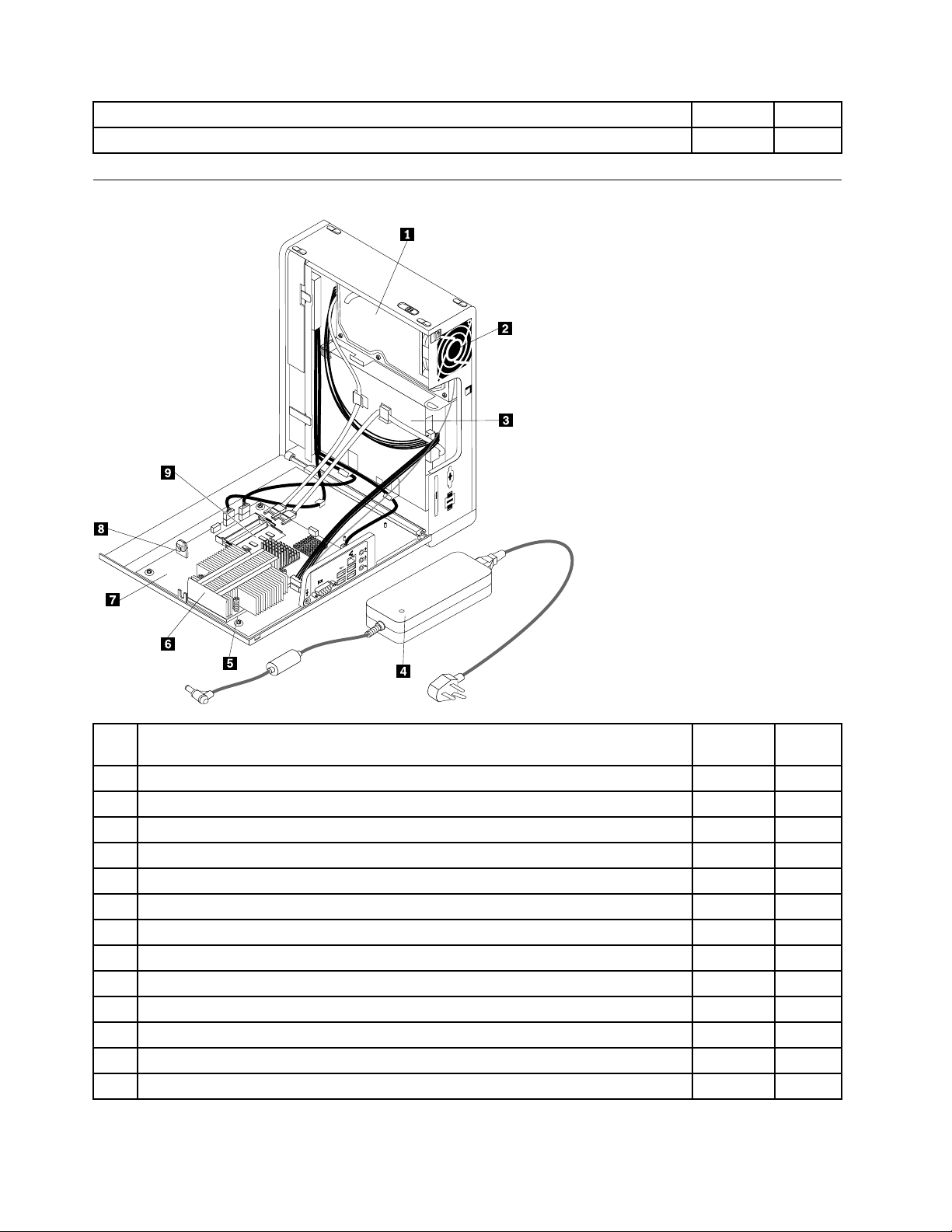
Japanese(models)
MachineType3980
3425Windows7Professional64RecoveryDVDsFRU#CRU
71Y81931
Item
#3980FRUsFRU#CRU
1
Harddiskdrive,SATA160GB7200RPM/3Gb/8M(models)
1
Harddiskdrive,SATA160GB7200RPM/3Gb/8M(models)
1
Harddiskdrive,SATA250GB7200RPM/3Gb/8M(models)
1
Harddiskdrive,SATA250GB7200RPM/3Gb/8M(models)
1
Harddiskdrive,SATA320GB7200RPM/3Gb/8M(models)
1
Harddiskdrive,SATA320GB7200RPM/3Gb/8M(models)
1
Harddiskdrive,SATA500GB7200RPM/3Gb/16M(models)
1
Harddiskdrive,SATA500GB7200RPM/3Gb/16M(models)
3
Opticaldrive,DVD-ROMDrive-16x/48x-SATA(models)
3
Opticaldrive,DVD-ROMDrive-16x/48x-SATA(models)
3
Opticaldrive,DVDRecordableRambo8-SAT A12XRAMWrite(models)43C1042
3
Opticaldrive,DVDRecordableRambo8-SAT A12XRAMWrite(models)
4
Powersupply,120Wac/dcpoweradapter(models)
40Y90351
53Y68371
40Y90361
45K04081
87H48911
45K04091
41X55821
45K04101
41N33251
71Y55431
71Y55451
41A97471
90HardwareMaintenanceManual
1
Page 97
Item
#3980FRUsFRU#CRU
5
Microprocessor,NTELCDCE14002/512/775/45WM0CPU2.00GHz,800MHz,512K,
71Y6133N
775QCJEM-0stepping45W(models)
5
Microprocessor,IntelPDCE52002.5/800/2/77545R0CPU2.50GHz,R-0Stepping,
71Y6132N
65nm,800MHzFSB,2MBL2,45W(models)
5
Microprocessor,Intel450Processor2.2/800/512/775A12.20GHz,A-1Stepping,
46R9514N
65nm,800MHzFSB,512KBL2,35W(models)
5
Microprocessor,IntelE54002.70GHz,800MHzFSB,2ML2R-0stepping,45W
71Y6419N
(models)
5
Microprocessor,IntelPDCE630045W2.80GHz,R-0Stepping,45nm,1066MHzFSB,
71Y6128N
2MBL2(models)
5
Microprocessor,WolfdaleCore2DuoE740045W2.80GHz,R-0stepping,1066MHz
71Y6421N
FSB,3MBL2(models)
5
Microprocessor,WolfdaleCore2DuoE760045W3.06GHz,1066MHzFSB,R-0
71Y6423N
stepping,3MBL2(models)
5
Microprocessor,WolfdaleCore2DuoE84003.0G/1333/6M/775QHFHE045W
71Y6130N
3.00GHz,E-0Stepping,45nm,1333MHzFSB,6MBL2(models)
5
Microprocessor,WolfdaleCore2DuoE85003.16G/1333/6M/775QHFGE045W
71Y6129N
3.16GHz,E-0Stepping,45nm,1333MHzFSB,6MBL2(models)
7
Systemboard,EG31GmITXHPlanar,G31_ALC662_8111Cnon-AMT(models)
9
Memorymodule,Hyn_RHY5PS1G831C1GBPC2-5300DDRII667MHz(models)
9
Memorymodule,Hyn_RH5PS1G83EFR-Y5C2GBPC2-5300-667MHz-DDR2
71Y6072N
71Y60911
71Y84691
SDRAM(modelsCTO)
TheFRUslistedinthefollowingtablesarenotillustrated.
3980FRUsFRU#CRU
Frontbezelassembly(allmodels)
Topcoverassembly(allmodels)
Chassis,main(allmodels)
Chassiscover(allmodels)
Plasticpartspackage(allmodels)
ODDretainer(allmodels)
ODDEMIshield(allmodels)
2H285mmSATAcable,angle,NoLatch(allmodels)
PowercableforODD&HDD,595(allmodels)
Metalchassisassembly(allmodels)
4.5LPCBALEDcable,310mm_R(allmodels)
Serialportcable(allmodels)
Systemfanassembly(allmodels)
3980Keyboards(LenovoPreferredProUSB--withouthub)FRU#CRU
Japanese(models)
45K61611
45K61621
45K6163N
45K6164N
45K61651
45K6166N
45K6168N
41R85101
45J95891
45K6170N
54Y99011
41R85481
45K63251
41A53101
Chapter9.FRUlists91
Page 98
Opticalwheelmouse(400DPI,USB)(models)
Opticalwheelmouse(400DPI,USB)(models)
3980PowerCords(Primary)FRU#CRU
LineCord-JapaneseandJapaneseEnglish(models)
3980PowerCords(Secondary)FRU#CRU
LineCord-JapaneseandJapaneseEnglish(models)
3980WindowsXPProRecoveryCDsFRU#CRU
Japanese(models)
3980VistaHomeBasic32RecoveryDVDsFRU#CRU
Japanese(models)
3980VistaBusiness32RecoveryDVDsFRU#CRU
Japanese(models)
3980miceFRU#CRU
41U30131
41U30301
42T50111
42T50961
71Y71121
71Y71201
71Y71161
3980VistaUltimate32/64RecoveryDVDsFRU#CRU
Japanese(models)
3980VistaHomePremium32/64RecoveryDVDsFRU#CRU
Japanese(models)
3980Windows7HomePremium32RecoveryDVDsFRU#CRU
Japanese(models)
3980Windows7Professional32RecoveryDVDsFRU#CRU
Japanese(models)
3980Windows7Professional64RecoveryDVDsFRU#CRU
Japanese(models)
71Y71211
71Y71191
71Y81921
71Y81891
71Y81931
92HardwareMaintenanceManual
Page 99
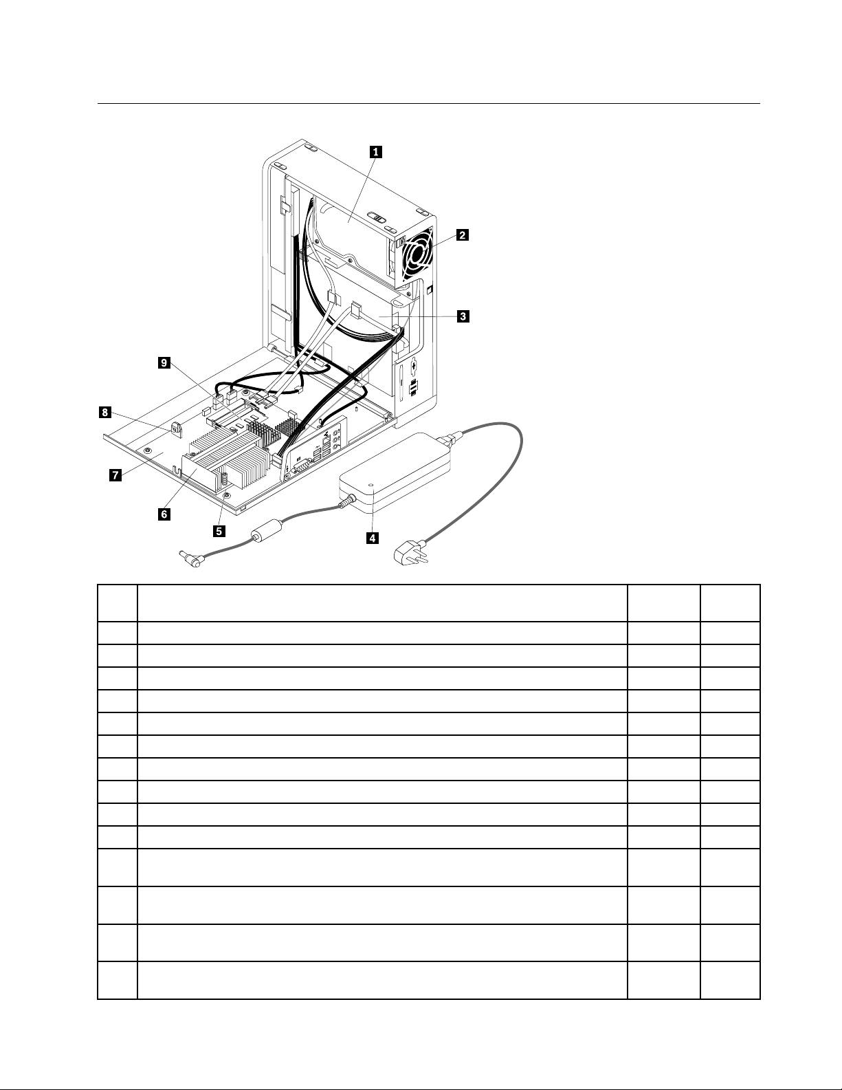
MachineType5214
Item
#5214FRUsFRU#CRU
1
Harddiskdrive,SAT A160GB7200RPM/3Gb/8M(modelsA1JA2JB3JB4J)
1
Harddiskdrive,SAT A160GB7200RPM/3Gb/8M(modelsA1JA2JB3JB4J)
1
Harddiskdrive,SATA250GB7200RPM/3Gb/8M(modelsA3JA4JA5JA6JB1JB2J)
1
Harddiskdrive,SATA250GB7200RPM/3Gb/8M(modelsA3JA4JA5JA6JB1JB2J)
1
Harddiskdrive,SATA320GB7200RPM/3Gb/8M(models)
1
Harddiskdrive,SATA320GB7200RPM/3Gb/8M(models)
1
Harddiskdrive,SATA500GB7200RPM/3Gb/16M(models)
1
Harddiskdrive,SATA500GB7200RPM/3Gb/16M(models)
3
Opticaldrive,DVD-ROMDrive-16x/48x-SATA(modelsA1JA3JA5JB1JB3J)
3
Opticaldrive,DVD-ROMDrive-16x/48x-SATA(modelsA1JA3JA5JB1JB3J)
3
Opticaldrive,DVDRecordableRambo8-SATA12XRAMWrite(modelsA2JA4J
A6JB2JB4J)
3
Opticaldrive,DVDRecordableRambo8-SATA12XRAMWrite(modelsA2JA4J
A6JB2JB4J)
4
Powersupply,120Wac/dcpoweradapter(modelsA1JA2JA3JA4JA5JA6JB1J
B2JB3JB4J)
5
Microprocessor,NTELCDCE14002/512/775/45WM0CPU2.00GHz,800MHz,512K,
775QCJEM-0stepping45W(models)
40Y90351
53Y68371
40Y90361
45K04081
87H48911
45K04091
41X55821
45K04101
41N33251
71Y55431
43C1042
71Y55451
41A97471
71Y6133N
1
Chapter9.FRUlists93
Page 100
Item
#5214FRUsFRU#CRU
5
Microprocessor,IntelPDCE52002.5/800/2/77545R0CPU2.50GHz,R-0Stepping,
65nm,800MHzFSB,2MBL2,45W(modelsA3JA4J)
5
Microprocessor,Intel450Processor2.2/800/512/775A12.20GHz,A-1Stepping,
65nm,800MHzFSB,512KBL2,35W(modelsA1JA2JB3JB4J)
5
Microprocessor,IntelE54002.70GHz,800MHzFSB,2ML2R-0stepping,45W
(models)
5
Microprocessor,IntelPDCE630045W2.80GHz,R-0Stepping,45nm,1066MHzFSB,
2MBL2(models)
5
Microprocessor,WolfdaleCore2DuoE740045W2.80GHz,R-0stepping,1066MHz
FSB,3MBL2(modelsA5JA6J)
5
Microprocessor,WolfdaleCore2DuoE760045W3.06GHz,1066MHzFSB,R-0
stepping,3MBL2(modelsB1JB2J)
5
Microprocessor,WolfdaleCore2DuoE84003.0G/1333/6M/775QHFHE045W
3.00GHz,E-0Stepping,45nm,1333MHzFSB,6MBL2(models)
5
Microprocessor,WolfdaleCore2DuoE85003.16G/1333/6M/775QHFGE045W
3.16GHz,E-0Stepping,45nm,1333MHzFSB,6MBL2(models)
7
Systemboard,EG31GmITXHPlanar,G31_ALC662_8111Cnon-AMT(modelsA1J
A2JA3JA4JA5JA6JB1JB2JB3JB4J)
9
Memorymodule,Hyn_RH5PS1G83EFR-Y5C2GBPC2-5300-667MHz-DDR2
SDRAM(modelsCTOB1JB2JB3JB4J)
9
Memorymodule,Hyn_RHY5PS1G831C1GBPC2-5300DDRII667MHz(modelsA1J
A2JA3JA4JA5JA6J)
71Y6132N
46R9514N
71Y6419N
71Y6128N
71Y6421N
71Y6423N
71Y6130N
71Y6129N
71Y6072N
71Y84691
71Y60911
TheFRUslistedinthefollowingtablesarenotillustrated.
5214FRUsFRU#CRU
Frontbezelassembly(allmodels)
Topcoverassembly(allmodels)
Chassis,main(allmodels)
Chassiscover(allmodels)
Plasticpartspackage(allmodels)
ODDretainer(allmodels)
ODDEMIshield(allmodels)
2H285mmSATAcable,angle,NoLatch(allmodels)
PowercableforODD&HDD,595(allmodels)
4.5LPCBALEDcable,310mm_R(allmodels)
Systemfanassembly(allmodels)
Metalchassisassembly(allmodels)
Serialportcable(allmodels)
5214Keyboards(LenovoPreferredProUSB--withouthub)FRU#CRU
Japanese(modelsA1JA2JA3JA4JA5JA6JB1JB2JB3JB4J)
45K61611
45K61621
45K6163N
45K6164N
45K61651
45K6166N
45K6168N
41R85101
45J95891
54Y99011
45K63251
45K6170N
41R85481
41A53101
94HardwareMaintenanceManual
 Loading...