

Page 1

Installation and User Guide
ThinkServer TD200
Machine Types: 3724, 3808, 3809, 3815, 3817, 3824, 3826, and 3836
Page 2

Page 3

ThinkServer TD200 Types 3724, 3808, 3809, 3815,
3817, 3824, 3826, 3836
Installation and User Guide
Page 4

Note:
Note: Before using this information and the product it supports, read the general information in Appendix B, “Notices,” on page 191
and the Warranty and Support Information document on ThinkServer Documentation DVD.
First Edition (June 2009)
© Copyright Lenovo 2009.
Portions © Copyright International Business Machines Corporation 2009.
LENOVO products, data, computer software, and services have been developed exclusively at private expense and
are sold to governmental entities as commercial items as defined by 48 C.F.R. 2.101 with limited and restricted rights
to use, reproduction and disclosure.
LIMITED AND RESTRICTED RIGHTS NOTICE: If products, data, computer software, or services are delivered
pursuant a General Services Administration ″GSA″ contract, use, reproduction, or disclosure is subject to restrictions
set forth in Contract No. GS-35F-05925.
Page 5

Contents
Safety ............................vii
Chapter 1. Introduction ......................1
Notices and statements in this document................2
Related documentation ......................3
Chapter 2. Server setup roadmap ..................5
Chapter 3. What is included with your server .............7
Features and technologies .....................7
Specifications ..........................9
Software ...........................12
EasyStartup .........................12
EasyManage.........................12
Reliability, availability, and serviceability................13
Chapter 4. Server controls, LEDs, and power.............15
Front view ..........................15
Operator information panel ....................19
EasyLED diagnostic panel.....................20
Rear view ...........................26
System-board internal connectors ..................28
System-board external connectors..................29
System-board option connectors ..................30
System-board switches and jumpers .................31
System-board LEDs .......................33
Optional one-slot PCI extender card .................34
Optional two-slot PCI extender card .................34
Server power features ......................35
Turning on the server .....................35
Turning off the server .....................35
Chapter 5. Installing optional devices and replacing customer replaceable
units............................37
Installation guidelines ......................37
System reliability guidelines ...................38
Working inside the server with the power on .............38
Handling static-sensitive devices .................39
Major components of the server ..................40
Opening the bezel........................40
Opening and closing the bezel media door...............42
Removing the side cover .....................43
Removing the air baffle ......................44
Removing the fan cage assembly ..................46
Installing the fan cage assembly ..................47
Removing the front USB connector assembly..............49
Installing the front USB connector assembly ..............51
Removing the rear adapter-retention bracket ..............52
Installing the rear adapter retention bracket ..............53
Removing the front adapter-retention bracket ..............54
Installing the front adapter-retention bracket ..............54
Removing the battery ......................54
Installing the battery .......................55
© Lenovo 2009. Portions © IBM Corp. 2009. iii
Page 6

Removing and installing drives ...................57
Removing a DVD drive .....................59
Installing a DVD drive .....................62
Removing an optional tape drive .................66
Installing an optional tape drive ..................67
Removing a 2.5-inch hot-swap hard disk drive ............70
Installing a 2.5-inch hot-swap hard disk drive .............71
Removing a 3.5-inch hot-swap hard disk drive ............73
Installing a 3.5-inch hot-swap hard disk drive .............74
Removing a simple-swap hard disk drive ..............75
Installing a simple-swap hard disk drive ...............76
IDs for hot-swap hard disk drives .................77
Power and signal cables for internal drives .............78
Removing a power supply .....................79
Installing a power supply .....................82
Removing a hot-swap fan .....................84
Installing a hot-swap fan .....................85
Removing a memory module ....................86
Installing a memory module ....................89
Removing an adapter ......................95
Installing an adapter .......................96
Installing a second microprocessor .................99
Removing a ServeRAID-BR10i SAS/SATA controller...........105
Installing the ServeRAID-BR10i SAS/SATA controller ..........106
Removing an optional ServeRAID-MR10i SAS/SATA controller .......111
Installing the optional ServeRAID-MR10i SAS/SATA controller .......112
Removing an optional ServeRAID-MR10is VAULT SAS/SATA controller ....118
Installing the optional ServeRAID-MR10is VAULT SAS/SATA controller ....118
Removing the virtual media key ..................125
Installing the virtual media key...................126
Removing the control-panel assembly ................127
Installing the control-panel assembly ................129
Completing the installation ....................130
Closing the bezel ......................130
Installing the air baffle .....................132
Installing the side cover ....................134
Connecting the cables.....................134
Updating the server configuration.................135
Connecting external devices ...................136
Chapter 6. Configuring the server.................137
Using the Setup Utility ......................138
Starting the Setup Utility ....................138
Setup Utility menu choices ...................138
Passwords .........................141
Configuring RAID controllers ...................142
Using the LSI Configuration Utility program .............143
Using the WebBIOS utility ....................145
Starting the WebBIOS utility ..................145
Main menu of the WebBIOS utility ................145
Creating a storage configuration using the Configuration Wizard .....146
Viewing and changing properties
Viewing and changing virtual disk properties ............146
Using the EasyStartup DVD....................147
Before you use the EasyStartup DVD...............147
Configuring RAID ......................148
.................146
iv ThinkServer TD200 Types 3724, 3808, 3809, 3815, 3817, 3824, 3826, 3836: Installation and User Guide
Page 7

EasyStartup overview .....................148
Installing your operating system without using EasyStartup .......150
Using the Boot Manager program .................150
Enabling the Broadcom Gigabit Ethernet Utility program .........151
Configuring the Broadcom Gigabit Ethernet controller ..........151
Updating the firmware ......................151
Starting the backup server firmware................152
Recovering the server firmware .................152
Automated boot recovery (ABR) ..................154
Three boot failure .......................154
Using the integrated management module ..............155
Using the remote presence capability and blue-screen capture .......156
Enabling the remote presence feature ...............156
Obtaining the IP address for the IMM ...............157
Logging on to the Web interface .................157
Diagnostics programs and messages ................158
Running the diagnostics programs ................158
Advanced Settings Utility program .................159
Installing EasyManage software ..................160
Installation requirements ....................160
Installation order .......................160
Installing Windows 2003 components on the Core Server ........161
Installing Windows 2008 32-bit components .............161
Uninstalling the LANDesk Software Agent .............162
Chapter 7. Troubleshooting ...................163
Troubleshooting tables .....................163
CD or DVD drive problems ...................163
Diskette drive problems ....................164
General problems ......................165
Hard disk drive problems....................165
Intermittent problems .....................166
Keyboard, mouse, or pointing-device problems............166
Memory problems ......................167
Microprocessor problems....................168
Monitor or video problems ...................168
Optional-device problems ...................170
Power problems .......................171
Serial port problems .....................172
Software problems ......................173
Universal Serial Bus (USB) port problems .............173
Solving undetermined problems ..................173
Solving SCSI problems .....................174
Solving power problems .....................175
Solving Ethernet controller problems ................175
POST ............................176
Event logs .........................176
POST error codes ......................178
Appendix A. Getting help and technical assistance ..........187
Before you call ........................187
Using the documentation .....................187
Getting help and information from the World Wide Web
.........187
Calling for service .......................188
Using other services ......................188
Purchasing additional services...................189
Contents v
Page 8

Lenovo product service .....................189
Appendix B. Notices ......................191
Trademarks..........................192
Important notes ........................192
Product recycling and disposal ..................193
Compliance with Republic of Turkey Directive on the Restriction of Hazardous
Substances .........................194
Recycling statements for Japan ..................195
Battery return program .....................195
German Ordinance for Work gloss statement .............196
Electronic emission notices ....................197
Federal Communications Commission (FCC) statement ........197
Industry Canada Class A emission compliance statement ........197
Avis de conformité à la réglementation d’Industrie Canada .......197
Australia and New Zealand Class A statement ............197
United Kingdom telecommunications safety requirement ........197
European Union EMC Directive conformance statement ........197
Germany Class A compliance statement ..............198
Japanese Voluntary Control Council for Interference (VCCI) statement 199
Taiwan Class A warning statement ................199
People's Republic of China Class A warning statement.........199
Korea Class A warning statement ................200
Index ............................201
vi ThinkServer TD200 Types 3724, 3808, 3809, 3815, 3817, 3824, 3826, 3836: Installation and User Guide
Page 9
Safety
Before installing this product, read the Safety Information.
Antes de instalar este produto, leia as Informações de Segurança.
Pred instalací tohoto produktu si prectete prírucku bezpecnostních instrukcí.
Læs sikkerhedsforskrifterne, før du installerer dette produkt.
Lees voordat u dit product installeert eerst de veiligheidsvoorschriften.
Ennen kuin asennat tämän tuotteen, lue turvaohjeet kohdasta Safety Information.
Avant d’installer ce produit, lisez les consignes de sécurité.
Vor der Installation dieses Produkts die Sicherheitshinweise lesen.
Prima di installare questo prodotto, leggere le Informazioni sulla Sicurezza.
Les sikkerhetsinformasjonen (Safety Information) før du installerer dette produktet.
Antes de instalar este produto, leia as Informações sobre Segurança.
Antes de instalar este producto, lea la información de seguridad.
Läs säkerhetsinformationen innan du installerar den här produkten.
© Lenovo 2009. Portions © IBM Corp. 2009. vii
Page 10

Important:
All caution and danger statements in this documentation begin with a number. This
number is used to cross reference an English caution or danger statement with
translated versions of the caution or danger statement in the Safety Information
book.
For example, if a caution statement begins with a number 1, translations for that
caution statement appear in the Safety Information document under statement 1.
Be sure to read all caution and danger statements in this documentation before
performing the instructions. Read any additional safety information that comes with
the blade server or optional device before you install the device.
viii ThinkServer TD200 Types 3724, 3808, 3809, 3815, 3817, 3824, 3826, 3836: Installation and User Guide
Page 11
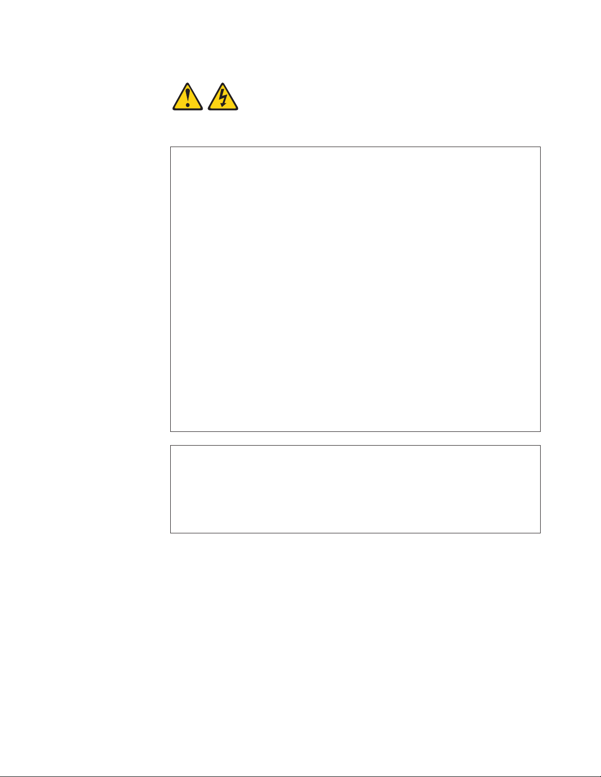
Statement 1:
DANGER
Electrical current from power, telephone, and communication cables is
hazardous.
To avoid a shock hazard:
v Do not connect or disconnect any cables or perform installation,
maintenance, or reconfiguration of this product during an electrical
storm.
v Connect all power cords to a properly wired and grounded electrical
outlet.
v Connect to properly wired outlets any equipment that will be attached to
this product.
v When possible, use one hand only to connect or disconnect signal
cables.
v Never turn on any equipment when there is evidence of fire, water, or
structural damage.
v Disconnect the attached power cords, telecommunications systems,
networks, and modems before you open the device covers, unless
instructed otherwise in the installation and configuration procedures.
v Connect and disconnect cables as described in the following table when
installing, moving, or opening covers on this product or attached
devices.
To Connect: To Disconnect:
1. Turn everything OFF.
2. First, attach all cables to devices.
3. Attach signal cables to connectors.
4. Attach power cords to outlet.
5. Turn device ON.
1. Turn everything OFF.
2. First, remove power cords from outlet.
3. Remove signal cables from connectors.
4. Remove all cables from devices.
Safety ix
Page 12

Statement 2:
CAUTION:
When replacing the lithium battery, use only a battery recommended by the
manufacturer. If your system has a module containing a lithium battery,
replace it only with the same module type made by the same manufacturer.
The battery contains lithium and can explode if not properly used, handled, or
disposed of.
Do not:
v Throw or immerse into water
v Heat to more than 100°C (212°F)
v Repair or disassemble
Dispose of the battery as required by local ordinances or regulations.
x ThinkServer TD200 Types 3724, 3808, 3809, 3815, 3817, 3824, 3826, 3836: Installation and User Guide
Page 13
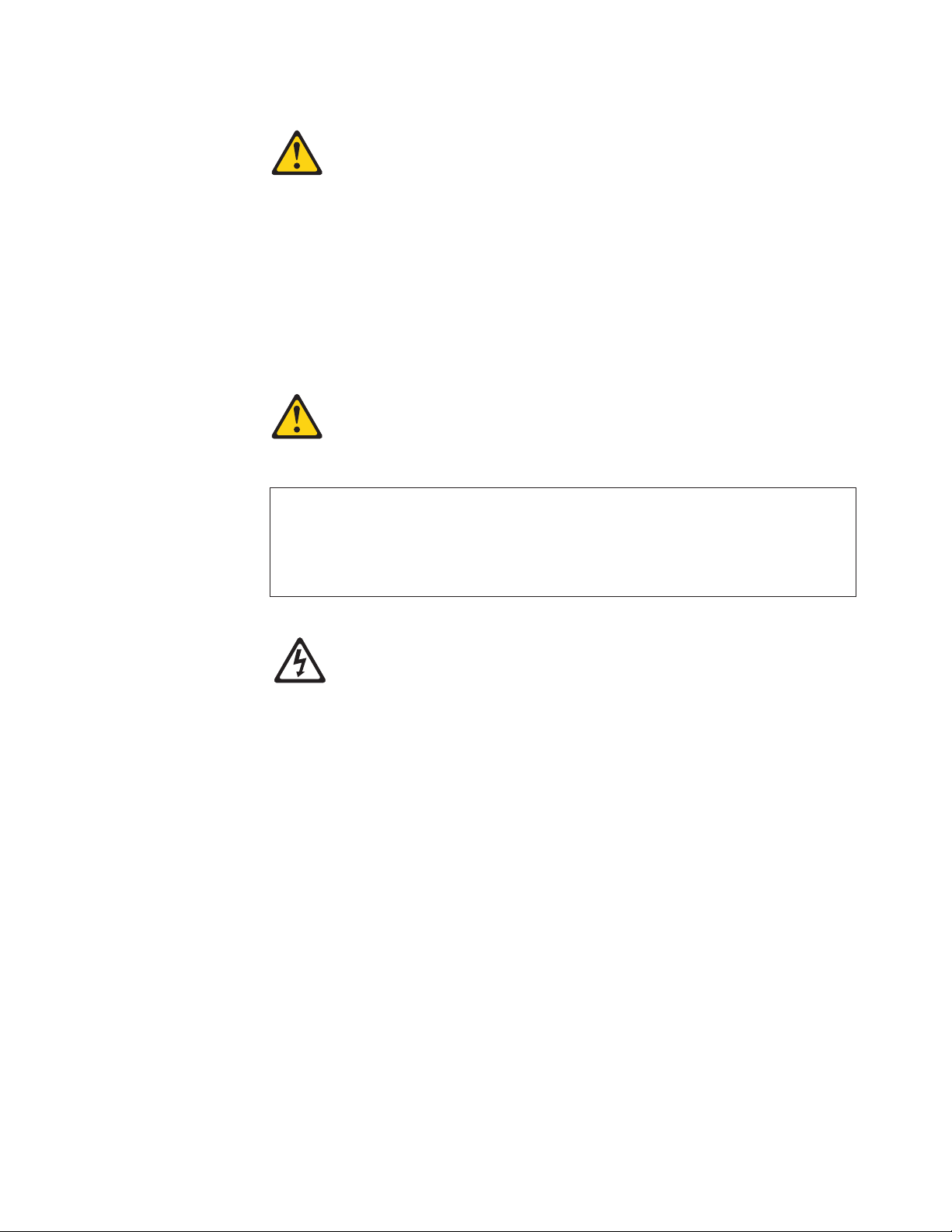
Statement 3:
CAUTION:
When laser products (such as CD-ROMs, DVD drives, fiber optic devices, or
transmitters) are installed, note the following:
v Do not remove the covers. Removing the covers of the laser product could
result in exposure to hazardous laser radiation. There are no serviceable
parts inside the device.
v Use of controls or adjustments or performance of procedures other than
those specified herein might result in hazardous radiation exposure.
DANGER
Some laser products contain an embedded Class 3A or Class 3B laser
diode. Note the following.
Laser radiation when open. Do not stare into the beam, do not view directly
with optical instruments, and avoid direct exposure to the beam.
Class 1 Laser Product
Laser Klasse 1
Laser Klass 1
Luokan 1 Laserlaite
Appareil A Laser de Classe 1
`
Safety xi
Page 14
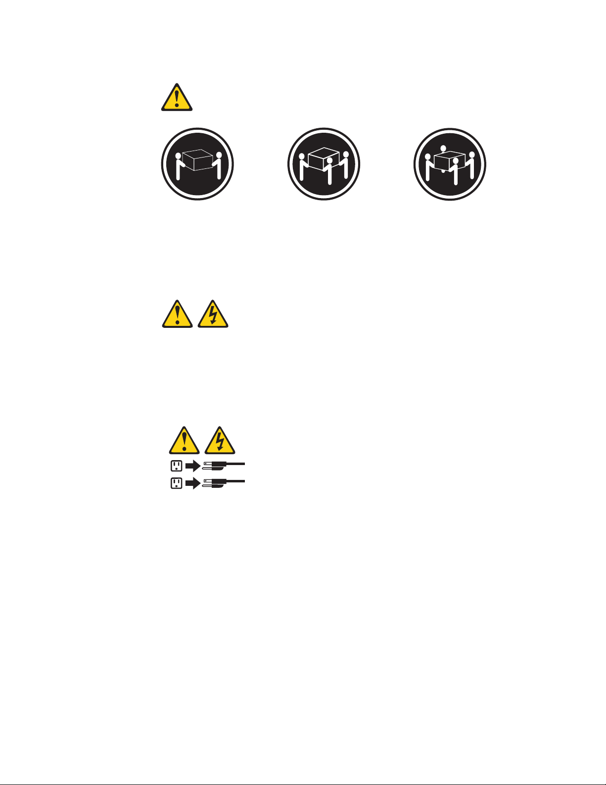
Statement 4:
≥ 18 kg (39.7 lb) ≥ 32 kg (70.5 lb) ≥ 55 kg (121.2 lb)
CAUTION:
Use safe practices when lifting.
Statement 5:
CAUTION:
The power control button on the device and the power switch on the power
supply do not turn off the electrical current supplied to the device. The device
also might have more than one power cord. To remove all electrical current
from the device, ensure that all power cords are disconnected from the power
source.
2
1
xii ThinkServer TD200 Types 3724, 3808, 3809, 3815, 3817, 3824, 3826, 3836: Installation and User Guide
Page 15
Statement 8:
CAUTION:
Never remove the cover on a power supply or any part that has the following
label attached.
Hazardous voltage, current, and energy levels are present inside any
component that has this label attached. There are no serviceable parts inside
these components. If you suspect a problem with one of these parts, contact
a service technician.
Statement 11:
CAUTION:
The following label indicates sharp edges, corners, or joints nearby.
Statement 12:
CAUTION:
The following label indicates a hot surface nearby.
Safety xiii
Page 16
Statement 13:
DANGER
Overloading a branch circuit is potentially a fire hazard and a shock hazard
under certain conditions. To avoid these hazards, ensure that your system
electrical requirements do not exceed branch circuit protection
requirements. Refer to the information that is provided with your device for
electrical specifications.
Statement 15:
CAUTION:
Make sure that the rack is secured properly to avoid tipping when the server
unit is extended.
Statement 17:
CAUTION:
The following label indicates moving parts nearby.
xiv ThinkServer TD200 Types 3724, 3808, 3809, 3815, 3817, 3824, 3826, 3836: Installation and User Guide
Page 17
Statement 26:
CAUTION:
Do not place any object on top of rack-mounted devices.
This server is suitable for use on an IT power-distribution system whose maximum
phase-to-phase voltage is 240 V under any distribution fault condition.
Important: This product is not suitable for use with visual display workplace
devices according to Clause 2 of the German Ordinance for Work with Visual
Display Units.
Safety xv
Page 18

xvi ThinkServer TD200 Types 3724, 3808, 3809, 3815, 3817, 3824, 3826, 3836: Installation and User Guide
Page 19

Chapter 1. Introduction
This Installation and User Guide contains information and instructions for setting up
your ThinkServer TD200 Types 3724, 3808, 3809, 3815, 3817, 3824, 3826, 3836
server, instructions for installing optional devices, and instructions for cabling and
configuring the server. For removing and installing optional devices, diagnostics and
troubleshooting information, see the Hardware Maintenance Manual.
The ThinkServer TD200 Types 3724, 3808, 3809, 3815, 3817, 3824, 3826, 3836 is
a 5-U-high, high-performance server. This server is ideally suited for networking
environments that require superior microprocessor performance, input/output (I/O)
flexibility, and manageability.
Performance, ease of use, reliability, and expansion capabilities were key
considerations in the design of the server. These design features make it possible
for you to customize the system hardware to meet your needs today and provide
flexible expansion capabilities for the future.
The server comes with a limited warranty. For information about the terms of the
warranty and getting service and assistance, see the Warranty and Support
Information document.
Some server models support four 3.5-inch simple-swap SATA hard disk drives, or
four 3.5-inch hot-swap SAS or SATA hard disk drives, or eight 2.5-inch hot-swap
SAS or SATA hard disk drives. The illustrations in this document might differ slightly
from your model.
If firmware and documentation updates are available, you can download them from
http://www.lenovo.com. The server might have features that are not described in the
documentation that comes with the server, and the documentation might be updated
occasionally to include information about those features, or technical updates might
be available to provide additional information that is not included in the server
documentation. To check for updates, do the following:
Note: Changes are made periodically to the Lenovo Web site. Procedures for
locating firmware and documentation might vary slightly from what is described in
this document.
1. Go to: http://www.lenovo.com/support.
2. Enter your product number (machine type and model number) or select Servers
and Storage from the Select your product list.
3. From Family list, select ThinkServer TD200, and click Continue.
4. Click Downloads and drivers to download firmware updates.
Record information about the server in the following table.
Product name ThinkServer TD200
Machine type 3724, 3808, 3809, 3815, 3817, 3824, 3826, 3836
Model number _____________________________________________
Serial number _____________________________________________
© Lenovo 2009. Portions © IBM Corp. 2009. 1
Page 20
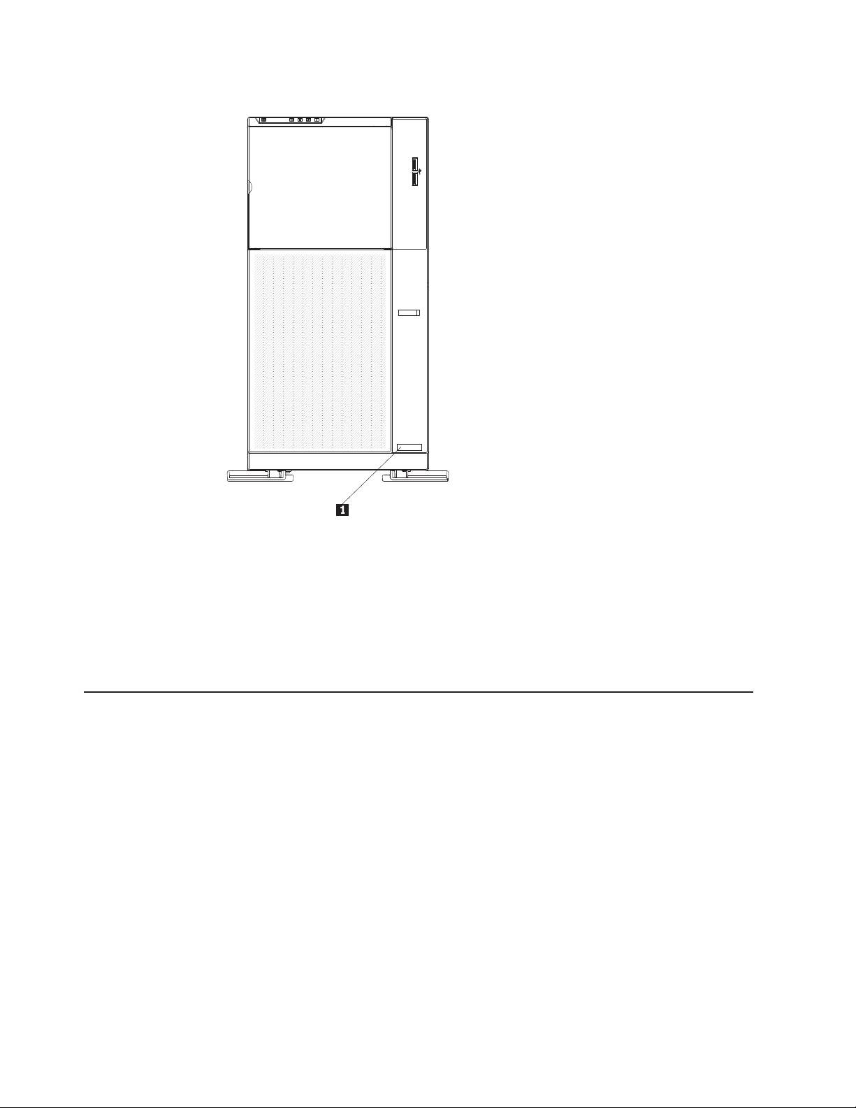
The model number and serial number are on the lower right side of the bezel. 1
Note: The illustrations in this document might differ slightly from your hardware.
The server comes with the ThinkServer EasyStartup DVD to help you configure the
hardware and install the operating system.
Important: The server keys cannot be duplicated by a locksmith. If you lose them,
order replacement keys from the key manufacturer. The key serial number and the
telephone number of the manufacturer are on a tag that is attached to the keys.
Notices and statements in this document
The caution and danger statements in this document are also in the multilingual
Safety Information document, which is on the Lenovo ThinkServer Documentation
DVD. Each statement is numbered for reference to the corresponding statement in
your language in the Safety Information document.
The following notices and statements are used in this document:
v Note: These notices provide important tips, guidance, or advice.
v Important: These notices provide information or advice that might help you avoid
inconvenient or problem situations.
v Attention: These notices indicate potential damage to programs, devices, or
data. An attention notice is placed just before the instruction or situation in which
damage might occur.
v Caution: These statements indicate situations that can be potentially hazardous
to you. A caution statement is placed just before the description of a potentially
hazardous procedure step or situation.
2 ThinkServer TD200 Types 3724, 3808, 3809, 3815, 3817, 3824, 3826, 3836: Installation and User Guide
Page 21
v Danger: These statements indicate situations that can be potentially lethal or
extremely hazardous to you. A danger statement is placed just before the
description of a potentially lethal or extremely hazardous procedure step or
situation.
Related documentation
The Lenovo ThinkServer Documentation DVD contains documentation for the
server in Portable Document Format (PDF). The Lenovo ThinkServer
Documentation DVD requires Adobe
comes with Linux®operating systems.
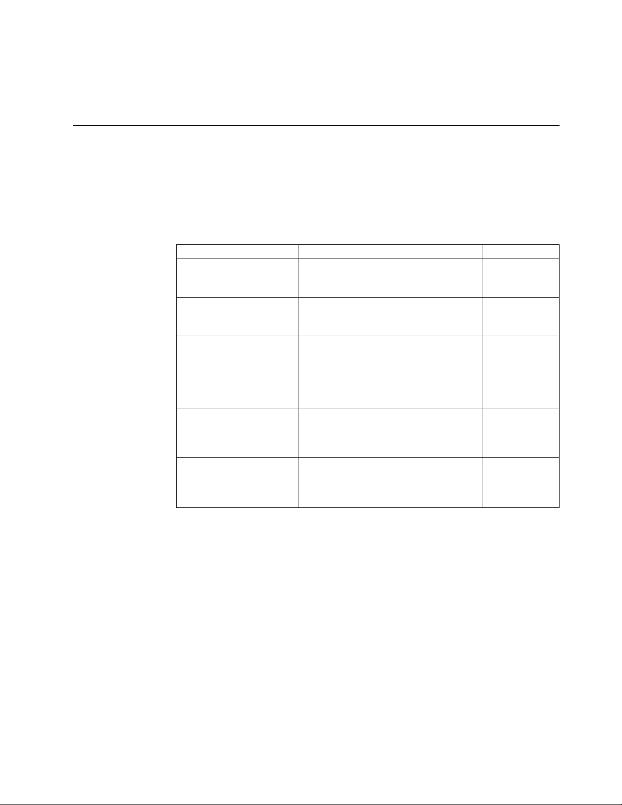
The following table describes the content and location of documentation that is
provided with your server.
Document Description Location
Read Me First This document directs you to the
Important Notices This document includes safety and legal
Hardware Maintenance
Manual
Warranty and Support
Information
Safety Information This document includes translations of all
®
Acrobat Reader 5.0 (or later) or xpdf, which
ThinkServer Documentation DVD for
complete warranty and support information.
notices that you are expected to read
before using the server.
This document provides diagnostic
information, parts listing, and replacement
procedures for all field replaceable units
(parts replaced by trained service
personnel) as well as all customer
replaceable units (CRUs).
This document includes the warranty
statement and information about how to
contact Lenovo Support.
of the safety statements used in the
ThinkServer documentation.
printed, provided
in server
packaging
printed, provided
in server
packaging
Lenovo Support
Web site:
http://
www.lenovo.com/
support
Available on the
ThinkServer
Documentation
DVD.
Available on the
ThinkServer
Documentation
DVD.
Chapter 1. Introduction 3
Page 22

4 ThinkServer TD200 Types 3724, 3808, 3809, 3815, 3817, 3824, 3826, 3836: Installation and User Guide
Page 23
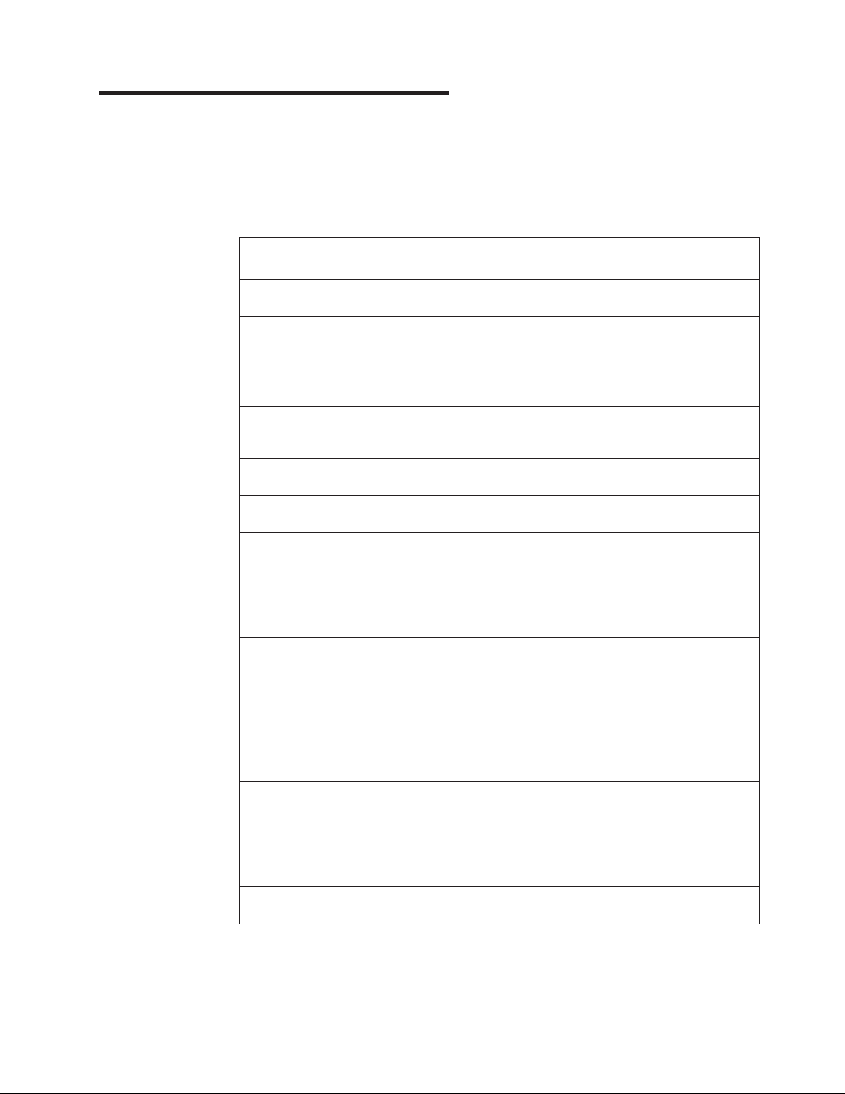
Chapter 2. Server setup roadmap
The installation process varies depending on the configuration of the server when it
was delivered. In some cases, the server is fully configured and just needs to be
installed in the rack, connected to power and the network, and started. In other
cases, the server needs to have hardware features installed, requires hardware and
firmware configuration, and required the operating system to be installed.
Task Where to find information
Unpack Chapter 3, “What is included with your server,” on page 7
Install hardware
features
Connect Ethernet cable
and power cords to
network and power
connectors
Start to verify operation “Turning on the server” on page 35
Review UEFI settings
and customize as
needed.
Configure RAID
controllers and arrays
Install operating system
and basic drivers
Install any additional
drivers needed for
added features
Configure Ethernet
settings in operating
system
Check for firmware and
driver updates.
Test IMM (requires the
presence of the virtual
media key option)
Install integrated
management
applications
Install applications Refer to the documentation that accompanies the applications that
Chapter 5, “Installing optional devices and replacing customer
replaceable units,” on page 37
“Rear view” on page 26
“Using the Setup Utility” on page 138
“Configuring RAID controllers” on page 142
“Using the EasyStartup DVD” on page 147
Refer to the instructions that came with the hardware option.
See the operating-system help. This step is not required if the
operating system was installed using the EasyStartup program.
See the Lenovo Support Web site:
1. Go to: http://www.lenovo.com/support.
2. Enter your product number (machine type and model number)
or select Servers and Storage from the Select your product
list.
3. From Family list, select ThinkServer TD200, and click
Continue.
4. Click Downloads and drivers to download firmware updates.
“Using the integrated management module” on page 155
“Installing EasyManage software” on page 160
you want to install.
© Lenovo 2009. Portions © IBM Corp. 2009. 5
Page 24

6 ThinkServer TD200 Types 3724, 3808, 3809, 3815, 3817, 3824, 3826, 3836: Installation and User Guide
Page 25
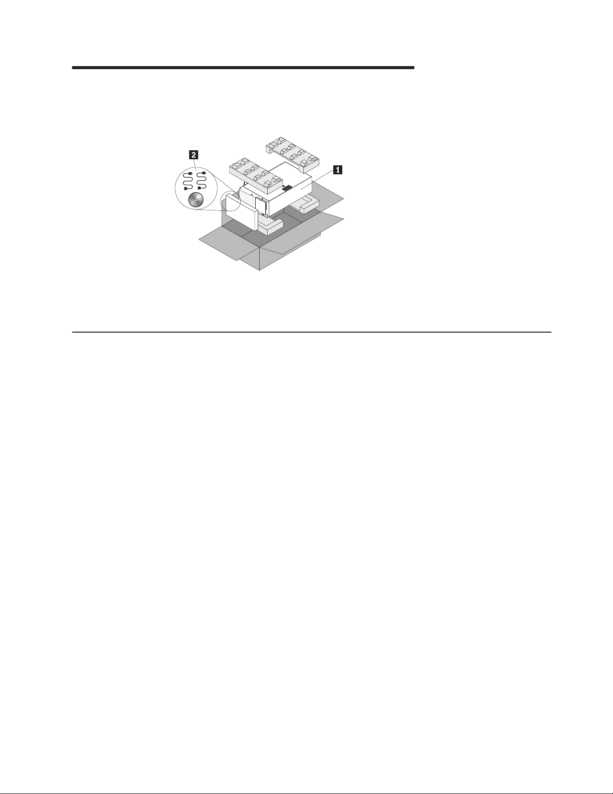
Chapter 3. What is included with your server
The TD200 server package includes the server, power cords, and the ThinkServer
Documentation DVD.
1 Server
2 Shipgroup box containing power cords and theThinkServer Documentation DVD
Features and technologies
The server uses the following features and technologies:
v Integrated Management Module
The Integrated Management Module (IMM) combines service processor
functions, video controller, and (when an optional virtual media key is installed)
remote presence function in a single chip. The IMM provides advanced
service-processor control, monitoring, and alerting function. If an environmental
condition exceeds a threshold or if a system component fails, the IMM lights
LEDs to help you diagnose the problem, records the error in the event log, and
alerts you to the problem. Optionally, the IMM also provides a virtual presence
capability for remote server management capabilities. The IMM provides remote
server management through the following industry-standard interfaces:
– Intelligent Platform Management Interface (IPMI) version 2.0
– Simple Network Management Protocol (SNMP) version 3
– Common Information Model (CIM)
– Web browser
For additional information, see “Using the integrated management module” on
page 155.
v UEFI-compliant server firmware
The UEFI-compliant server firmware offers several features, including Unified
Extensible Firmware Interface (UEFI) version 2.1 compliance, enhanced
reliability, availability, and serviceability (RAS) capabilities, and basic input/output
system (BIOS) compatibility support. UEFI replaces the legacy BIOS. UEFI
defines a standard interface between the operating system, platform firmware
and external devices, and offers capabilities that far exceeds that of the legacy
BIOS.
The server design combines the UEFI capabilities and features with legacy BIOS
compatibility. The server is capable of booting UEFI-compliant operating systems,
BIOS-based operating systems, and BIOS-based adapters as well as
UEFI-compliant adapters.
© Lenovo 2009. Portions © IBM Corp. 2009. 7
Page 26

Note: The server does not support Disk Operating System (DOS).
v Preboot diagnostics program
The preboot diagnostics programs are stored on the integrated USB memory.
They collect and analyze system information to aid in diagnosing server
problems. The diagnostics programs collect the following information about the
server:
– System configuration
– Network interfaces and settings
– Installed hardware
– EasyLED status
– Service processor status and configuration
– Vital product data, firmware, and UEFI (formerly called BIOS) configuration
– Hard disk drive health
– RAID controller configuration
– Event logs for RAID controllers and service processors
The diagnostics programs create a merged log that includes events from all
collected logs. The information is collected into a file that you can send to service
and support. Additionally, you can view the information locally through a
generated text report file. You can also copy the log to a removable media and
view the log from a Web browser.
For additional information about diagnostics, see the Hardware Maintenance
Manual.
v High-performance graphics controller
The server comes with an onboard high-performance graphics controller that
supports high resolutions and includes many performance-enhancing features for
the operating-system environment.
v Integrated network support
The server comes with an integrated dual-port Broadcom Gigabit Ethernet
controller, which supports connection to a 10 Mbps, 100 Mbps, or 1000 Mbps
network. For more information, see “Enabling the Broadcom Gigabit Ethernet
Utility program” on page 151.
v Integrated Trusted Platform Module (TPM)
This integrated security chip performs cryptographic functions and stores private
and public secure keys. It provides the hardware support for the Trusted
Computing Group (TCG) specification. You can download the software to support
the TCG specification, when the software is available. You can enable TPM
support through the Setup Utility under the System Security menu option.
v Large data-storage capacity and hot-swap capabilities
Some hot-swap server models support eight slim-high, 2.5-inch hot-swap hard
disk drives or four 3.5-inch hot-swap hard disk drives (depending on the model).
With the hot-swap feature, you can add, remove, or replace hard disk drives
without turning off the server.
v Large system-memory capacity
The server supports up to 48 GB (reduced to 24 GB in mirroring mode) of
system memory. The memory controller supports error correcting code (ECC) for
up to 12 industry-standard PC3-10600R-999 (single-rank or dual-rank), 800,
1067, and 1333 MHz, DDR3 (third-generation double-data-rate), registered,
synchronous dynamic random access memory (SDRAM) dual inline memory
modules (DIMMs).
v Memory mirroring
8 ThinkServer TD200 Types 3724, 3808, 3809, 3815, 3817, 3824, 3826, 3836: Installation and User Guide
Page 27

Some models support memory mirroring. Memory mirroring replicates and stores
data on two pairs of DIMMs within two channels (channel 0 and 1)
simultaneously. If a failure occurs, the memory controller switches from the
primary pair of memory DIMMs to the backup pair of DIMMs. To support memory
mirroring, you must install a pair of DIMMs at a time. One DIMM must be in
channel 0, and the mirroring DIMM must be in the same slot in channel 1. For
more information, see 91.
v RAID support
The ServeRAID adapter provides hardware redundant array of independent disks
(RAID) support to create configurations. The standard RAID adapter provides
RAID levels 0, 1, and 1E. The optional RAID adapters are available for purchase
and provide RAID levels 0, 1, 5, 6, 10, 50, and 60. See “Installing an adapter” on
page 96 and “Using the LSI Configuration Utility program” on page 143 for more
information about supported adapters and creating RAID arrays.
v Symmetric multiprocessing (SMP)
The server supports up to two Intel Xeon microprocessors. Each microprocessor
provides symmetric multiprocessing capability. When you install the second
microprocessor, this will enhance the performance of the server.
v Systems-management capabilities
The server comes with an integrated management module (IMM). When the IMM
is used with the systems-management software that comes with the server, you
can manage the functions of the server locally and remotely. The IMM also
provides system monitoring, event recording, and network alert capability. The
systems-management connector on the rear of the server is dedicated to the
IMM. The dedicated systems-management connector provides additional security
by physically separating the management network traffic from the production
network. You can use the Setup Utility to configure the server to use a dedicated
systems-management network or a shared network.
v TCP/IP offload engine (TOE) support
The Ethernet controllers in the server support TOE, which is a technology that
offloads the TCP/IP flow from the microprocessor and I/O subsystem to increase
the speed of the TCP/IP flow. When an operating system that supports TOE is
running on the server and TOE is enabled, the server supports TOE operation.
See the operating-system documentation for information about enabling TOE.
The Windows operating system requires that the Windows Scalable Network
Pack (SNP) be installed for TOE support.
Specifications
Note: As of the date of this document, the Linux operating system does not
support TOE.
The following information is a summary of the features and specifications for
machine types 3724, 3808, 3809, 3815, 3817, 3824, 3826, 3836. Depending on the
server model, some features might not be available, or some specifications might
not apply.
Chapter 3. What is included with your server 9
Page 28
Table 1. Features and specifications
Microprocessor:
v Supports up to two Intel
dual-core or quad-core microprocessors
(one installed) with integrated memory
controller and QuickPath Interconnect
(QPI) architecture. The second
microprocessor comes with a pluggable
VRM
v Designed for LGA 1366 socket
v Scalable up to four cores
v 32 KB instruction cache, 32 KB data
cache, and 8 MB cache that is shared
among the cores
v Support for Intel Extended Memory 64
Technology (EM64T)
Note:
v Use the Setup Utility to determine the
type and speed of the microprocessors.
v For a list of supported microprocessors,
see http://www.lenovo.com/thinkserver.
Memory:
v Minimum: 2 GB
v Maximum: 48 GB (24 GB in mirrored
mode)
v Types: PC3-10600R-900 (single-rank or
dual-rank, 800, 1066, and 1333 MHz,
ECC, DDR3 registered SDRAM DIMMs
only)
v Connectors: twelve dual inline memory
module (DIMM) connectors, two-way
interleaved
v Supports 1 GB, 2 GB, 4 GB, and 8 GB
(when available)
®
Pentium
®
Fans:
Three speed-controlled hot-swap fans
Power supply: One 670 watt (100 - 240 V
ac)
Size:
v Height: 440 mm (17.3 in.)
v Depth: 767 mm (30.2 in.)
v Width: 218 mm (8.6 in.)
v Weight: 20 kg (42 lb) to 34 kg (75 lb)
depending upon configuration
RAID controllers:
v A ServeRAID-BR10i SAS/SATA adapter
that provides RAID levels 0, 1, and 1E
(comes standard on some hot-swap
SAS and hot-swap SATA models).
v An optional ServeRAID-MR10i
SAS/SATA adapter that provides RAID
levels 0, 1, 5, 6, 10, 50, and 60 can
also be ordered.
v An optional ServeRAID-MR10is
SAS/SATA adapter that provides RAID
levels 0, 1, 5, 6, 10, 50, and 60 can
also be ordered.
10 ThinkServer TD200 Types 3724, 3808, 3809, 3815, 3817, 3824, 3826, 3836: Installation and User Guide
Page 29

Table 1. Features and specifications (continued)
Drives (depending on the model):
v Optical drives: SATA
v Hard disk drives: SAS and SATA
Drive bays (depending on the model):
v Three 5.25-in. bays (one half-high
DVD-ROM drive installed). Optionally
you can install one full-high or two
half-high internal tape drives in bays 2
and 3.
v One of the following:
– Four 3.5-inch simple-swap SATA
drives
– Four 3.5-inch hot-swap SAS or SATA
drives
– Eight 2.5-inch hot-swap SAS or
SATA drives
Integrated functions:
v Integrated Management Module (IMM),
which provides service processor
control and monitoring functions, video
controller, and (when the optional virtual
media key is installed) remote
keyboard, video, mouse, and remote
hard disk drive capabilities
v Broadcom BCM5709 Gb Ethernet
controller with TCP/IP Offload Engine
(TOE) and Wake on LAN
v Onboard SATA controller (simple-swap
models)
v Seven Universal Serial Bus (USB) 2.0
ports (two front and four rear of the
chassis), and one for the internal USB
tape drive.
v Two Ethernet ports
v One System Management RJ-45 on the
rear to connect to a
systems-management network. This
systems-management connector is
dedicated to the IMM functions. This
connector is active with or without the
optional Virtual Media Key installed.
v One serial port
v Six SATA ports (four through the iPASS
connector for simple-swap drives and
two for the optical drives)
®
support
Acoustical noise emissions:
v Sound power, idling: 5.5 bel
v Sound power, operating: 6.0 bel
Environment:
v Air temperature:
– Server on: 10° to 35°C (50° to 95°F)
Altitude: 0 to 915 m (3000 ft)
– Server on: 10° to 32°C (50° to 90°F)
Altitude: 0 to 915 m (3000 ft) to 2134
m (7000 ft)
– Server on: 10° to 28°C (50° to 83°F)
Altitude: 2134 m (7000 ft) to 3050 m
(10000 ft)
– Server off: 5° to 45°C (41.0° to
113°F)
– Shipping: -40° to 60°C (-40° to
140°F)
v Humidity (operating and storage):
– Server on: 20% to 80%, Maximum
dew point 21°C, Maximum rate of
change 5°C/hr.
– Server off: 8% to 80%, Maximum
dew point 27°C
Heat output:
Approximate heat output in British thermal
units (Btu) per hour:
v Minimum configuration: 693 Btu per
hour (203 watts)
v Maximum configuration: 2788 Btu per
hour (817 watts)
Chapter 3. What is included with your server
11
Page 30
Table 1. Features and specifications (continued)
Up to eight expansion slots (depending
on the model):
v Six expansion slots on the system
board
– Four PCI Express Gen2 x8 slots
(two x8 links and two x4 link)
– One PCI Express Gen2 x16 slot (x8
link)
– One PCI 32-bit/33 MHz slot
v One PCI Express Gen1 x8 (x4) slot on
the one-slot extender card
v Two PCI-X 32-bit/64-bit 133/100/66/
MHz slots on the two-slot extender card
Video controller (integrated into IMM):
v Matrox G200eV video graphics
controller integrated on the system
board
– Compatible with SVGA and VGA
– 8 MB DDR2 SDRAM video memory
controller
Note: The maximum video resolution is
1600 x 1200 at 85 MHz
Diagnostic LEDs:
v Fan
v Microprocessor
v Memory
v Power supply
v Voltage regulator module (VRM)
v PCI
v Battery
v IMM heartbeat
v Enclosure manager heartbeat
Electrical input:
v Sine-wave input (50 or 60 Hz) required
v Input voltage and frequency ranges
automatically selected
v Input voltage low range:
– Minimum: 100 V ac
– Maximum: 127 V ac
v Input voltage high range:
– Minimum: 200 V ac
– Maximum: 240 V ac
v Input kilovolt-amperes (kVA)
approximately:
– Minimum: 0.21 kVA (all models)
– Maximum: 0.82 kVA
Notes:
1. Power consumption and heat output
vary depending on the number and
type of optional features installed and
the power-management optional
features in use.
2. These levels were measured in
controlled acoustical environments
according to the procedures specified
by the American National Standards
Institute (ANSI) S12.10 and ISO 7779
and are reported in accordance with
ISO 9296. Actual sound-pressure
levels in a given location might exceed
the average values stated because of
room reflections and other nearby
noise sources. The declared
sound-power levels indicate an upper
limit, below which a large number of
computers will operate.
Software
Lenovo provides software to help get your server up and running.
EasyStartup
The EasyStartup program simplifies the process of configuring your RAID
controllers and installing supported Windows and Linux operating systems and
device drivers on your server. The EasyStartup program is provided with your
server on DVD. The DVD is self starting (bootable). The User Guide for the
EasyStartup program is on the DVD and can be accessed directly from the
program's interface. For additional information, see “Using the EasyStartup DVD” on
page 147.
EasyManage
The ThinkServer EasyManage Core server provides centralized hardware and
software inventory management and secure automated systems management
through a centralized console. The ThinkServer EasyManage Agent enables other
clients on the network to be managed by the centralized console. The ThinkServer
EasyManage Core Server is supported on 32-bit Windows Server 2003 and 32-bit
Windows Server 2008 products. The ThinkServer EasyManage Agent is supported
on 32-bit and 64-bit Windows, Red Hat, and SUSE operating systems.
12 ThinkServer TD200 Types 3724, 3808, 3809, 3815, 3817, 3824, 3826, 3836: Installation and User Guide
Page 31

Reliability, availability, and serviceability
Three important server design features are reliability, availability, and serviceability
(RAS). The RAS features help to ensure the integrity of the data that is stored in
the server, the availability of the server when you need it, and the ease with which
you can diagnose and repair problems.
The server might have the following RAS features (the features vary depending on
your model):
v Advanced Configuration and Power Interface (ACPI)
v Advanced Desktop Management Interface (DMI) features
v Automatic error retry or recovery
v Automatic memory downsizing on error detection
v Automatic restart on nonmaskable interrupt (NMI)
v Automatic Server Restart (ASR) logic supporting a system restart when the
operating system becomes unresponsive
v Automatic server restart after a power failure, based on the UEFI setting
v Availability of microcode level
v Boot-block recovery
v Built-in, menu-driven setup, system configuration, and redundant array of
independent disks (RAID) configuration
v Built-in monitoring for fan, power, temperature, and voltage
v Cooling fans with speed-sensing capability
v Customer support center that is available 24 hours a day, 7 days a week
Note: Service availability will vary by country. Response time varies; may
exclude holidays.
™
v Diagnostic support of ServeRAID
adapters
v Error codes and messages
v Error correcting code (ECC) double-data-rate 3 (DDR3) synchronous dynamic
random-access memory (SDRAM) with serial presence detect (SPD)
v Error logging of POST failures
v Hot-swap Serial Attached SCSI (SAS) and hot-swap Serial ATA (SATA) hard disk
drives
v Integrated Ethernet controller
v Key-lock support for physical security
v Memory change messages posted to the error log
v Integrated management module (IMM)
v Power management
v Power-on self-test (POST)
v Read-only memory (ROM) checksums
v ROM-based diagnostics programs
v Simple-swap Serial Advanced Technology Attachment (SATA) hard disk drives
v Standby voltage for systems-management features and monitoring
v System auto-configuring from the configuration menu
v System-error LED on the front bezel and diagnostic LEDs on the system board
v Upgradeable integrated management module (IMM) firmware
Chapter 3. What is included with your server 13
Page 32

v Upgradeable microcode for POST, server firmware, and read-only memory
(ROM) resident code, locally or over a LAN
v Vital product data (VPD); includes serial-number information and replacement
part numbers, stored in nonvolatile memory, for easier remote maintenance
14 ThinkServer TD200 Types 3724, 3808, 3809, 3815, 3817, 3824, 3826, 3836: Installation and User Guide
Page 33

Chapter 4. Server controls, LEDs, and power
This section describes the controls, light-emitting diodes (LEDs), and connectors on
the front and rear of the server, and how to turn the server on and off. For the
location of the LEDs on the system board, see “System-board LEDs” on page 33.
Note: The illustrations in this document might differ slightly from your model.
Front view
The following illustrations show the controls, LEDs, and connectors on the front of
the server models.
The following is an illustration of the 3.5-inch SAS/SATA hot-swap hard disk drive
model:
1 Power-on LED 7 DVD-eject button
2 Power-control button 8 Hard disk drive activity LED (green)
3 Hard disk drive activity LED 9 Hard disk drive status LED (amber)
4 System-error LED 10 DVD drive activity LED (green)
5 USB 2 11 Front information panel
6 USB 1
The following is an illustration of the 2.5-inch SAS/SATA hot-swap hard disk drive
model:
© Lenovo 2009. Portions © IBM Corp. 2009. 15
Page 34

1 Power-on LED 7 DVD-eject button
2 Power-control button 8 Hard disk drive activity LED (green)
3 Hard disk drive activity LED 9 Hard disk drive status LED (amber)
4 System-error LED 10 DVD drive activity LED (green)
5 USB 2 11 Front information panel
6 USB 1
The following is an illustration of the 3.5-inch SATA simple-swap hard disk drive
model:
16 ThinkServer TD200 Types 3724, 3808, 3809, 3815, 3817, 3824, 3826, 3836: Installation and User Guide
Page 35

1 Power-on LED 6 USB 1
2 Power-control button 7 DVD-eject button
3 Hard disk drive activity LED 8 Simple-swap hard disk drive
4 System-error LED 9 DVD drive activity LED (green)
5 USB 2 10 Information panel
Power control button and power-on LED
Press this button to turn the server on and off manually or to wake the
server from a reduced-power state. The states of the power-on LED are as
follows:
Off: ac power is not present, or the power supply or the LED itself has
failed.
Flashing rapidly (4 times per second): The server is turned off and is
not ready to be turned on. The power-control button is disabled. This will
last approximately 1 to 3 minutes.
Flashing slowly (once per second): The server is turned off and is
ready to be turned on. You can press the power-control button to turn on
the server.
Lit: The server is turned on.
Fading on and off: The server is in a reduced-power state. To wake the
server, press the power-control button or use the IMM Web interface.
See “Logging on to the Web interface” on page 157 for information on
logging on to the IMM Web interface.
Hard disk drive activity LED
When this LED is flashing rapidly, it indicates that a hard disk drive is in
use.
System-error LED
When this amber LED is lit, it indicates that a system error has occurred.
Chapter 4. Server controls, LEDs, and power 17
Page 36

An LED on the system board might also be lit to help isolate the error.
Detailed troubleshooting information is in the Hardware Maintenance
Manual.
USB connectors
Connect USB devices to these connectors.
DVD-eject button
Press this button to release a CD or DVD from the DVD drive.
DVD drive activity LED
When this LED is lit, it indicates that the DVD drive is in use.
Hot-swap hard disk drive activity LED (some models)
On some server models, each hot-swap drive has a hard disk drive activity
LED. When this green LED is flashing, it indicates that the associated hard
disk drive is in use.
When the drive is removed, this LED also is visible on the SAS/SATA
backplane, next to the drive connector. The backplane is the printed circuit
board behind drive bays 4 through 7 on 3.5-inch hard disk drive models and
bays 4 through 11 on 2.5-inch hard disk drive models.
Hot-swap hard disk drive status LED (some models)
On some server models, each hot-swap hard disk drive has an amber
status LED. If this amber status LED is lit, it indicates that the associated
hard disk drive has failed.
If an optional ServeRAID adapter is installed in the server and the LED
flashes slowly (one flash per second), the drive is being rebuilt. If the LED
flashes rapidly (three flashes per second), the adapter is identifying the
drive.
When the drive is removed, this LED also is visible on the SAS/SATA
backplane, below the hot-swap hard disk drive activity LED.
18 ThinkServer TD200 Types 3724, 3808, 3809, 3815, 3817, 3824, 3826, 3836: Installation and User Guide
Page 37

Operator information panel
The following illustration shows the LEDs on the operator information panel on the
front of the server.
1 System power-on LED
2 Hard disk drive activity LED
3 System-locator LED
4 System-information LED
5 System-error LED
v Follow the suggested actions in the order in which they are listed in the Action column until the problem
is solved.
v See the Hardware Maintenance Manual to determine which components are customer replaceable units
(CRUs) and which components are field replaceable units (FRUs).
v If an action step is preceded by “(Trained service technician only),” that step must be performed only by a
trained service technician.
Lit EasyLED; diagnostic LEDs with the
system-error or information LED also lit Description
System power-on (green) The states of the power-on LED are as follows:
v Off: ac power is not present, or the power supply or the LED itself
has failed.
v Flashing rapidly (4 times per second): The server is turned off
and is not ready to be turned on. The power-control button is
disabled. Approximately 3 minutes after the server is connected to
ac power, the power-control button becomes active.
v Flashing slowly (once per second): The server is turned off and is
ready to be turned on. You can press the power-control button to
turn on the server.
v Lit: The server is turned on.
v Fading on and off: The server is in a reduced-power state. To
wake the server, press the power-control button or use the IMM
Web interface.
Chapter 4. Server controls, LEDs, and power 19
Page 38

v Follow the suggested actions in the order in which they are listed in the Action column until the problem
is solved.
v See the Hardware Maintenance Manual to determine which components are customer replaceable units
(CRUs) and which components are field replaceable units (FRUs).
v If an action step is preceded by “(Trained service technician only),” that step must be performed only by a
trained service technician.
Lit EasyLED; diagnostic LEDs with the
system-error or information LED also lit Description
Hard-disk drive activity (green) When this LED is flashing rapidly, it indicates that there is activity on a
hard disk drive.
System locator (blue) Use this LED to visually locate the server among other servers.
System information (amber) When this amber LED is on, it indicates that information about a
suboptimal condition in the server is available in the IMM event log or
in the system-event log. Check the EasyLED diagnostic panel for more
information.
System error (amber) When this LED is lit, it indicates that a system error has occurred. Use
the diagnostic LED panel and the system service label to further isolate
the error.
EasyLED diagnostic panel
The following illustration shows the front LEDs on the EasyLED diagnostic panel.
The EasyLED diagnostic panel is located inside the front bezel.
Note: The EasyLED diagnostics LEDs remain lit only while the server is connected
to power.
1 Server processor bus 8 Power supply
2 Microprocessor 9 Fan
3 VRM 10 PCI bus
4 Microprocessor/memory configuration 11 System board
5 Memory 12 Temperature
6 NMI 13 System-event log
7 Hard disk drive/RAID 14 USB ports
20 ThinkServer TD200 Types 3724, 3808, 3809, 3815, 3817, 3824, 3826, 3836: Installation and User Guide
Page 39

v Follow the suggested actions in the order in which they are listed in the Action column until the problem
is solved.
v See the Hardware Maintenance Manual to determine which components are customer replaceable units
(CRUs) and which components are field replaceable units (FRUs).
v If an action step is preceded by “(Trained service technician only),” that step must be performed only by a
trained service technician.
Lit EasyLED
diagnostics LED with
the system-error or
information LED also
lit Description Action
System-event log
(LOG)
Temperature The system temperature has
A system error occurred. View the contents of the system-event log (see “Event
logs” on page 176).
exceeded a threshold level.
1. See the system-event log for the source of the
fault (see “Event logs” on page 176).
2. Make sure that the airflow in the server is not
blocked.
3. Make sure that the room temperature is neither too
hot nor too cold (see “Environment” in “Features
and technologies” on page 7).
System board (BRD) An error occurred on the system
board.
1. Check the LEDs on the system board to identify
the component that is causing the error. The BRD
LED can be lit for the following conditions:
v Failed or missing battery
v Failed voltage regulator
2. Check the system-event log for information about
the error.
3. Replace any failed or missing replaceable
components, such as the battery.
4. (Trained service technician only) If a voltage
regulator has failed, replace the system board.
PCI bus A PCI adapter has failed.
1. See the system-event log (see “Event logs” on
page 176).
2. Check the LEDs on the PCI slots to identify the
component that is causing the error, and reseat the
failing adapter.
3. Replace the following components one at a time,
in the order shown, restarting the server each time:
a. Failing adapter
b. (Trained service technician only) System board
Fan A fan has failed or is operating too
slowly.
1. Reinstall the removed fan.
2. If an individual fan LED is lit, replace the fan.
3. (Trained service technician only) Replace the
system board.
Chapter 4. Server controls, LEDs, and power 21
Page 40

v Follow the suggested actions in the order in which they are listed in the Action column until the problem
is solved.
v See the Hardware Maintenance Manual to determine which components are customer replaceable units
(CRUs) and which components are field replaceable units (FRUs).
v If an action step is preceded by “(Trained service technician only),” that step must be performed only by a
trained service technician.
Lit EasyLED
diagnostics LED with
the system-error or
information LED also
lit Description Action
Power supply A power supply has failed or has
been removed.
Note: In a redundant power
configuration, the dc power LED on
one power supply might be off.
DASD/RAID A hard disk drive, SAS controller, or
RAID adapter error has occurred.
Notes:
1. This LED is also lit when a hard
disk drive is removed from the
server.
2. The error LED on the failing
hard disk drive is also lit.
3. Check the system-event log for
a RAID error.
NMI A hardware error has been reported
to the operating system.
1. Check the individual power-supply LEDs.
2. Reseat the following components:
a. Power supply
b. (Trained service technician only) Power-supply
cage cables
3. Replace the following components one at a time,
in the order shown, restarting the server each time:
a. Power supply
b. (Trained service technician only) Power-supply
cage
1. Reinstall the removed drive.
2. Reseat the following components:
a. Failing hard disk drive
b. SAS hard disk drive backplane
c. SAS signal and power cables
d. System board
e. ServeRAID adapter
3. Replace the components one at a time, in the
order shown, restarting the server each time.
1. See the system-event log (see “Event logs” on
page 176).
2. If the PCI LED is lit, follow the instructions for that
LED.
3. If the MEM LED is lit, follow the instructions for
that LED.
4. Restart the server.
22 ThinkServer TD200 Types 3724, 3808, 3809, 3815, 3817, 3824, 3826, 3836: Installation and User Guide
Page 41

v Follow the suggested actions in the order in which they are listed in the Action column until the problem
is solved.
v See the Hardware Maintenance Manual to determine which components are customer replaceable units
(CRUs) and which components are field replaceable units (FRUs).
v If an action step is preceded by “(Trained service technician only),” that step must be performed only by a
trained service technician.
Lit EasyLED
diagnostics LED with
the system-error or
information LED also
lit Description Action
Memory (MEM) A memory error has occurred.
Note: The error LED on the DIMM
is also lit.
1. Determine whether the CNFG LED is also lit,
which indicates that the memory configuration is
invalid. Reinstall the DIMMs in a supported
configuration.
2. If the CNFG LED is not lit, one of the following
conditions might be present:
v The server did not start and a failing DIMM LED
is lit:
a. Check for a PFA log event in the
system-event log.
b. Reseat the DIMM.
c. Move the DIMM to a different slot or replace
the DIMM.
d. (Trained service technician only) Replace
the system board.
v The server started, the failing DIMM is disabled,
and the LED is lit:
a. If the LEDs are lit by two DIMMs, check the
system-event log for a PFA event on one of
the DIMMs, and then replace that DIMM.
Otherwise, replace both DIMMs.
b. If the LED is lit by only one DIMM, replace
that DIMM.
c. Re-enable the DIMM, using the Setup Utility.
Microprocessor/
Memory Configuration
(CNFG)
A hardware configuration error has
occurred. (This LED is used with the
MEM, VRM, and CPU LEDs.)
1. (The system-error LED, CPU LED, and this LED
are lit when POST detects a microprocessor
mismatch.) Remove and install two
microprocessors of the same cache size, type, and
clock speed.
2. (The system-error LED, MEM LED, and this LED
are lit when POST detects an invalid memory
configuration.) Remove and install supported
DIMMs (see “Removing a memory module” on
page 86 and “Installing a memory module” on
page 89).
3. (The system-error LED, VRM LED, and this LED
are lit when POST detects a missing VRM.) Install
a VRM for microprocessor 2 (see “Installing a
second microprocessor” on page 99).
4. Check the system-error log for information
indicating incompatible components.
Chapter 4. Server controls, LEDs, and power 23
Page 42

v Follow the suggested actions in the order in which they are listed in the Action column until the problem
is solved.
v See the Hardware Maintenance Manual to determine which components are customer replaceable units
(CRUs) and which components are field replaceable units (FRUs).
v If an action step is preceded by “(Trained service technician only),” that step must be performed only by a
trained service technician.
Lit EasyLED
diagnostics LED with
the system-error or
information LED also
lit Description Action
VRM A VRM has failed.
Microprocessor (CPU) A microprocessor has failed, or an
invalid microprocessor configuration
is installed.
Note: (Trained service technician
only) Make sure that the
microprocessors are installed in the
correct sequence.
1. Check the system-event log to determine the
reason for the lit LED (for a VRM).
2. Determine whether the CNFG LED is also lit. If the
CNFG LED is lit, the memory configuration is
invalid. Reseat the VRM.
3. If the CNFG LED is not lit, reseat the following
components:
a. Failing VRM
b. (Trained service technician only)
Microprocessor associated with the VRM
4. Replace the following components one at a time,
in the order shown, restarting the server each time:
a. Failing VRM
b. (Trained service technician only)
Microprocessor associated with the VRM
c. (Trained service technician only) System board
1. Check the system-event log to determine the
reason for the lit LED.
2. Determine whether the CNFG LED is also lit. If the
CNFG LED is not lit, a microprocessor has failed.
a. Make sure that the failing microprocessor,
which is indicated by the CPU1 or CPU2 error
LED on the system board, is installed correctly.
b. Replace the following components one at a
time, in the order shown, restarting the server
each time:
1) (Trained service technician only) Failing
microprocessor
2) (Trained service technician only) System
board
c. If the CNFG LED is lit and the CPU mismatch
LED on the system board is also lit, an invalid
microprocessor configuration is installed:
1) Make sure that the microprocessors are
compatible with each other. They must
match in speed and cache size. Use the
Setup Utility to compare the microprocessor
information.
2) (Trained service technician only) Replace
the incompatible microprocessor.
24 ThinkServer TD200 Types 3724, 3808, 3809, 3815, 3817, 3824, 3826, 3836: Installation and User Guide
Page 43

v Follow the suggested actions in the order in which they are listed in the Action column until the problem
is solved.
v See the Hardware Maintenance Manual to determine which components are customer replaceable units
(CRUs) and which components are field replaceable units (FRUs).
v If an action step is preceded by “(Trained service technician only),” that step must be performed only by a
trained service technician.
Lit EasyLED
diagnostics LED with
the system-error or
information LED also
lit Description Action
Service processor bus
(SP BUS)
The IMM detects an internal error.
1. Disconnect the server from ac power; then,
reconnect the server to power and restart the
server.
2. Update the IMM firmware.
1. The following table lists the EasyLED diagnostics LEDs, the problems that they
indicate, and actions to solve the problems.
Look at the system service label on the top of the server, which gives an
overview of internal components that correspond to the LEDs on the EasyLED
diagnostic panel. This information can often provide enough information to
diagnose the error.
2. Remove the server cover and look inside the server for lit LEDs. Certain
components inside the server have LEDs that are lit to indicate the location of a
problem (See “System-board LEDs” on page 33).
The following illustration shows the LEDs on the system board.
Chapter 4. Server controls, LEDs, and power 25
Page 44

Rear view
The following illustration shows the LEDs and connectors on the rear of the server.
1 Power cord connector 10 USB 1
2 Ethernet transmit/receive
activity LED
3 Ethernet link status LED 12 NMI button
4 Ethernet transmit/receive
activity LED
5 Ethernet link status LED 14 Video
6 Ethernet 2 10/100/1000 15 Serial 1 (COM 1)
7 USB 4 16 Fault (error) LED
8 USB 3 17 ac power LED
9 USB 2 18 dc power LED
11 Ethernet 1 10/100/1000
13 Systems-management Ethernet connector
Power-cord connector
Connect the power cord to this connector.
ac power LED
This green LED provides status information about the power supply. During
typical operation, both the ac and dc power LEDs are lit. For any other
combination of LEDs, see the Hardware Maintenance Manual.
dc power LED
This green LED provides status information about the power supply. During
typical operation, both the ac and dc power LEDs are lit. For any other
combination of LEDs, see the Hardware Maintenance Manual.
26 ThinkServer TD200 Types 3724, 3808, 3809, 3815, 3817, 3824, 3826, 3836: Installation and User Guide
Page 45

Power-error (Fault) LED
When this amber LED is lit, it indicates that the power supply has failed.
For any other combination of LEDs, see the Hardware Maintenance
Manual.
Video connector
Connect a monitor to this connector.
Note: The maximum video resolution is 1600 x 1200 at 60 MHz.
Serial connector
Connect a 9-pin serial device to this connector.
Systems-management Ethernet connector
Use this connector to manage the server, using a dedicated management
network. If you use this connector, the IMM cannot be accessed directly
from a production network. A dedicated management network provides
additional security by physically separating the management network traffic
from the production network. You can use the Setup Utility to configure the
server to use a dedicated systems-management network or a shared
network.
USB connectors
Connect USB devices to these connectors.
Ethernet connectors
Use these connectors to connect the server to a network.
Ethernet transmit/receive activity LED
This LED is on the Ethernet connector on the rear of the server. When this
LED is lit, it indicates that there is activity between the server and the
network.
Ethernet link status LED
This LED is on the Ethernet connector on the rear of the server. When this
LED is lit, it indicates that there is an active connection on the Ethernet
port.
Chapter 4. Server controls, LEDs, and power 27
Page 46

System-board internal connectors
The following illustration shows the internal connectors on the system board.
1 Main power 12 Reserved
2 Reserved 13 Simple-swap SATA signal cable connector
3 Optical power 14 Hot-swap main fan connector
4 Front panel connector 15 SATA 0 (optical drive connector)
5 Reserved 16 SATA 1
6 USB internal tape drive
signal connector
7 Reserved 18 Battery
8 Front USB connector 19 PCI extender card connector
9 Reserved 20 Microprocessor 1
10 Hard disk drive backplane
configuration signal cable
connector
11 Hard disk drive backplane
configuration signal cable
connector
17 Reserved
21 Virtual media key connector
22 Power connector 2
28 ThinkServer TD200 Types 3724, 3808, 3809, 3815, 3817, 3824, 3826, 3836: Installation and User Guide
Page 47

System-board external connectors
The following illustration shows the external input/output (I/O) connectors on the
system board.
1 Power connector 6 USB 1-2
2 Serial (COM 1) 7 Ethernet 1
3 Video 8 USB 3-4
4 Systems-management
Ethernet connector
5 NMI button
9 Ethernet 2
Chapter 4. Server controls, LEDs, and power 29
Page 48

System-board option connectors
The following illustration shows the system-board connectors for user-installable
options.
1 DIMM 9 (reserved) 15 DIMM 2
2 DIMM 10 16 DIMM 1 (reserved)
3 DIMM 11 17 Battery
4 DIMM 12 (reserved) 18 PCI extender card connector
5 DIMM 13 19 Microprocessor 1
6 DIMM 14 20 Microprocessor 2
7 DIMM 15 21 Slot 6, PCI 32 bit/33 MHz
8 DIMM 16 22 Slot 5, PCI Express Gen2 x8 (x8)
9 DIMM 8 23 Slot 4, PCI Express Gen2 x8 (x4)
10 DIMM 7 24 Slot 3, PCI Express Gen2 x8 (x4)
11 DIMM 6 25 Slot 2, PCI Express Gen2 x18 (x8)
12 DIMM 5 26 Slot 1, PCI Express Gen2 x8 (x8)
13 DIMM 4 (reserved) 27 Virtual media key connector
14 DIMM 3 28 Optional VRM connector
Note: Do not insert memory DIMMs into connectors marked as reserved. These
DIMM slots are not supported in this model.
30 ThinkServer TD200 Types 3724, 3808, 3809, 3815, 3817, 3824, 3826, 3836: Installation and User Guide
Page 49

System-board switches and jumpers
The following illustration shows the switches and jumpers on the system board.
1 UEFI boot recovery jumper (JP8)
2 Clear CMOS jumper (JP1)
3 SW8 switch block
The following table describes the jumpers on the system board.
Table 2. System-board jumpers
Jumper number Jumper name Jumper setting
JP1 Clear CMOS jumper
Chapter 4. Server controls, LEDs, and power 31
v Pins 1 and 2: Normal
(default) - This keeps the
CMOS data.
v Pins 2 and 3: This clears
the CMOS data, which
clears the power-on
password and
administrator password.
Page 50

Table 2. System-board jumpers (continued)
Jumper number Jumper name Jumper setting
JP6 UEFI boot recovery jumper
Notes:
v If no jumper is present, the server responds as if the pins are set to 1 and 2.
v Do not change the jumper pin position after the server is turned on. Changing the
position of the UEFI boot recovery jumper from pins 1 and 2 to pins 2 and 3 before the
server is turned on alters which flash ROM page is loaded. This can cause an
unpredictable problem.
v Pins 1 and 2: Normal
(default) - Loads the
primary server firmware
ROM.
v Pins 2 and 3: This enables
the server to recovery if
the server firmware
becomes damaged.
The following table describes the function of each pin on the SW6 switch block.
Table 3. System-board switches
Switch pin number Default value Description
1 Off Reserved.
2 Off Power-on password override.
Changing the position of this
switch bypasses the
power-on password check
the next time the server is
turned on and starts the
Setup Utility so that you can
change or delete the
power-on password. You do
not have to move the switch
back to the default position
after the power-on password
is overridden.
Changing the position of this
switch does not affect the
administrator password check
if an administrator password
is set.
See “Passwords” on page
141 for additional information
about passwords.
3 Off Reserved.
4Off
v When this switch is on Off,
this is normal mode. This
loads the primary IMM
firmware ROM page.
v When this switch is
toggled to On, this loads
the secondary (backup)
IMM firmware ROM page.
32 ThinkServer TD200 Types 3724, 3808, 3809, 3815, 3817, 3824, 3826, 3836: Installation and User Guide
Page 51

Important:
1. Before you change any switch settings or move any jumpers, turn off the server,
then, disconnect all power cords and external cables. Read the safety
information (see “Safety” on page vii, “Handling static-sensitive devices” on
page 39, and “Working inside the server with the power on” on page 38).
2. Any system-board switch blocks or jumpers that are not shown in the
illustrations in this document are reserved.
System-board LEDs
The following illustration shows the light-emitting diodes (LEDs) on the system
board.
Chapter 4. Server controls, LEDs, and power 33
Page 52

1 Microprocessor mismatch
LED
2 Microprocessor 2 error LED 10 PCI slot 5 error LED
3 DIMMs 9-18 error LEDs 11 PCI slot 4 error LED
4 DIMMs 1-8 error LEDs 12 Enclosure manager heartbeat LED
5 Microprocessor 1 error LED 13 PCI slot 3 error LED
6 System-board error LED 14 PCI slot 2 error LED
7 Battery error LED 15 PCI slot 1 error LED
8 IMM heartbeat LED 16 VRM error LED
For more information about the system-board LEDs, see the Hardware Maintenance
Manual.
Optional one-slot PCI extender card
The following is an illustration of the one-slot PCI extender card that you can install
to add an additional PCI slot to the server.
9 PCI slot 6 error LED
1 PCI Express Gen1 x8 (x4) slot
2 One-slot extender card
3 PCI slot error LED
Optional two-slot PCI extender card
The following is an illustration of the two-slot PCI extender cards that you can install
to add two additional PCI slots to the server.
1 PCI-X 32-bit/84-bit 133/100/66 MHz slots
2 Two-slot extender card
3 PCI slots error LEDs
34 ThinkServer TD200 Types 3724, 3808, 3809, 3815, 3817, 3824, 3826, 3836: Installation and User Guide
Page 53

Server power features
When the server is connected to an ac power source but is not turned on, the
operating system does not run, and all core logic except for the service processor
(the Integrated Management Module) is shut down; however, the server can
respond to requests to the service processor, such as a remote request to turn on
the server. The power-on LED flashes to indicate that the server is connected to ac
power but is not turned on.
Turning on the server
Approximately 5 seconds after the server is connected to ac power, one or more
fans might start running to provide cooling while the server is connected to power
and the power-on button LED will blink quickly. Approximately 1 to 3 minutes after
the server is connected to ac power, the power-control button becomes active (the
power-on LED will blink slowly). You can turn on the server by pressing the
power-control button.
The server can also be turned on in any of the following ways:
v If a power failure occurs while the server is turned on, the server will restart
automatically when power is restored.
Note: When 4 GB or more of memory (physical or logical) is installed, some
memory is reserved for various system resources and is unavailable to the
operating system. The amount of memory that is reserved for system resources
depends on the operating system, the configuration of the server, and the
configured peripheral component interconnect (PCI) options.
Turning off the server
When you turn off the server and leave it connected to ac power, the server can
respond to requests to the service processor, such as a remote request to turn on
the server. While the server remains connected to ac power, one or more fans
might continue to run. To remove all power from the server, you must disconnect it
from the power source.
Some operating systems require an orderly shutdown before you turn off the server.
See your operating-system documentation for information about shutting down the
operating system.
Statement 5:
CAUTION:
The power control button on the device and the power switch on the power
supply do not turn off the electrical current supplied to the device. The device
also might have more than one power cord. To remove all electrical current
from the device, ensure that all power cords are disconnected from the power
source.
Chapter 4. Server controls, LEDs, and power 35
Page 54

2
1
The server can be turned off in any of the following ways:
v You can turn off the server from the operating system, if your operating system
supports this feature. After an orderly shutdown of the operating system, the
server will be turned off automatically.
v You can press the power-control button to start an orderly shutdown of the
operating system and turn off the server, if your operating system supports this
feature.
v If the operating system stops functioning, you can press and hold the
power-control button for more than 4 seconds to turn off the server.
v The integrated management module (IMM) can turn off the server as an
automatic response to a critical system failure.
36 ThinkServer TD200 Types 3724, 3808, 3809, 3815, 3817, 3824, 3826, 3836: Installation and User Guide
Page 55

Chapter 5. Installing optional devices and replacing customer replaceable units
Important: Before you install optional hardware, make sure that the server is
working correctly. Start the server, and make sure that the operating system starts,
if an operating system is installed. If the server is not working correctly, see the
Hardware Maintenance Manual and “Troubleshooting tables” on page 163 for
diagnostic information.
This chapter provides detailed instructions for installing optional hardware devices in
the server.
Installation guidelines
Before you install options, read the following information:
v Read the safety information (see “Safety” on page vii, “Handling static-sensitive
devices” on page 39, and “Working inside the server with the power on” on page
38). This information will help you work safely.
v When you install your new server, take the opportunity to download and apply
the most recent firmware updates. This step will help to ensure that any known
issues are addressed and that your server is ready to function at maximum levels
of performance. To download firmware updates for your server, do the following:
1. Go to: http://www.lenovo.com/support.
2. Enter your product number (machine type and model number) or select
Servers and Storage from the Select your product list.
3. From Family list, select ThinkServer TD200, and click Continue.
4. Click Downloads and drivers to download firmware updates.
v Before you install optional hardware, make sure that the server is working
correctly. Start the server, and make sure that the operating system starts, if an
operating system is installed. If the server is not working correctly, see the
Hardware Maintenance Manual for diagnostic information.
v Observe good housekeeping in the area where you are working. Place removed
covers and other parts in a safe place.
v If you must start the server while the cover is removed, make sure that no one is
near the server and that no tools or other objects have been left inside the
server.
v Do not attempt to lift an object that you think is too heavy for you. If you have to
lift a heavy object, observe the following precautions:
– Make sure that you can stand safely without slipping.
– Distribute the weight of the object equally between your feet.
– Use a slow lifting force. Never move suddenly or twist when you lift a heavy
object.
– To avoid straining the muscles in your back, lift by standing or by pushing up
with your leg muscles.
v Make sure that you have an adequate number of properly grounded electrical
outlets for the server, monitor, and other devices.
v Back up all important data before you make changes to disk drives.
v Have a small flat-blade screwdriver, a small Phillips screwdriver, and a T8 torx
screwdriver available.
© Lenovo 2009. Portions © IBM Corp. 2009. 37
Page 56

v You do not have to turn off the server to install or replace hot-swap fans and
hot-swap drives.
v Blue on a component indicates touch points, where you can grip the component
to remove it from or install it in the server, open or close a latch, and so on.
v Orange on a component or an orange label on or near a component indicates
that the component can be hot-swapped, which means that if the server and
operating system support hot-swap capability, you can remove or install the
component while the server is running. (Orange can also indicate touch points on
hot-swap components.) See the instructions for removing and installing a specific
hot-swap component for any additional procedures that you might have to
perform before you remove or install the component.
v When you have to access the inside of the server, you might find it easier to
position the server on its side.
v When you are finished working on the server, reinstall all safety shields, guards,
labels, and ground wires.
v For a list of supported options for the server, see http://www.lenovo.com/
thinkserver.
System reliability guidelines
To help ensure proper system cooling and system reliability, make sure that the
following requirements are met:
v Each of the drive bays has a drive or a filler panel and electromagnetic
compatibility (EMC) shield installed in it.
v There is adequate space around the server to allow the server cooling system to
work properly. Leave approximately 50 mm (2.0 in.) of open space around the
front and rear of the server. Do not place objects in front of the fans. For proper
cooling and airflow, replace the server cover before turning on the server.
Operating the server for extended periods of time (more than 30 minutes) with
the server cover removed might damage server components.
v You have followed the cabling instructions that come with optional adapters.
v You have replaced a failed fan as soon as possible.
v You have replaced a hot-swap fan within 30 seconds of removal.
v You have replaced a hot-swap drive within 2 minutes of removal.
v You do not operate the server without the air baffle installed. Operating the
server without the air baffle might cause the microprocessor to overheat.
Working inside the server with the power on
Attention: Static electricity that is released to internal server components when
the server is powered on might cause the server to halt, which could result in the
loss of data. To avoid this potential problem, always use an electrostatic-discharge
wrist strap or other grounding system when working inside the server with the
power on.
The server (some models) supports hot-swap devices and is designed to operate
safely while it is turned on and the cover is removed. Follow these guidelines when
you work inside a server that is turned on.
v Avoid wearing loose-fitting clothing on your forearms. Button long-sleeved shirts
before working inside the server; do not wear cuff links while you are working
inside the server.
v Do not allow your necktie or scarf to hang inside the server.
38 ThinkServer TD200 Types 3724, 3808, 3809, 3815, 3817, 3824, 3826, 3836: Installation and User Guide
Page 57

v Remove jewelry, such as bracelets, necklaces, rings, and loose-fitting wrist
watches.
v Remove items from your shirt pocket, such as pens and pencils, that could fall
into the server as you lean over it.
v Avoid dropping any metallic objects, such as paper clips, hairpins, and screws,
into the server.
Handling static-sensitive devices
Attention: Static electricity can damage the server and other electronic devices.
To avoid damage, keep static-sensitive devices in their static-protective packages
until you are ready to install them.
To reduce the possibility of electrostatic discharge, observe the following
precautions:
v Limit your movement. Movement can cause static electricity to build up around
you.
v The use of a grounding system is recommended. For example, wear an
electrostatic-discharge wrist strap, if one is available. Always use an
electrostatic-discharge wrist strap or other grounding system when working inside
the server with the power on.
v Handle the device carefully, holding it by its edges or its frame.
v Do not touch solder joints, pins, or exposed circuitry.
v Do not leave the device where others can handle and damage it.
v While the device is still in its static-protective package, touch it to an unpainted
metal surface on the outside of the server for at least 2 seconds. This drains
static electricity from the package and from your body.
v Remove the device from its package and install it directly into the server without
setting down the device. If it is necessary to set down the device, put it back into
its static-protective package. Do not place the device on the server cover or on a
metal surface.
v Take additional care when handling devices during cold weather. Heating reduces
indoor humidity and increases static electricity.
Chapter 5. Installing optional devices and replacing customer replaceable units 39
Page 58

Major components of the server
The following illustration shows the major components in the server (depending on
the server model). The illustrations in this document might differ slightly from your
hardware.
1 Bezel 15 ServeRAID MR10is
2 Optical drive bay EMC
3 2.5-inch EMC shield 17 Rear adapter retention bracket
4 3.5-inch EMC shield 18 Air baffle
5 2.5-inch hot-swap 19 Heat sink
6 3.5-inch hot-swap 20 Microprocessor
7 3.5-inch simple-swap drive 21 Heat sink retention bracket
8 SAS/SATA 2.5-inch
9 SAS/SATA 3.5-inch
10 Simple-swap 3.5-inch
11 Fan assembly 25 Power supply
12 Hot-swap fan 26 Control panel assembly
13 ServeRAID MR10i 27 USB cable assembly
14 ServeRAID BR10i 28 DVD drive
Opening the bezel
To open the bezel, do the following:
Note: The illustrations in this document might differ slightly from your hardware.
1. Read the safety information (see “Safety” on page vii and “Installation
2. Unlock the side cover.
16 Cover
shield
22 DIMMs
backplane
23 System board
backplane
24 VRM
backplane
guidelines” on page 37).
40 ThinkServer TD200 Types 3724, 3808, 3809, 3815, 3817, 3824, 3826, 3836: Installation and User Guide
Page 59

Note: You must unlock the side cover to open or remove the bezel. When you
lock the server side cover, it locks both the cover and the bezel.
3. Remove the bezel. Position your finger on the depressed area on the left side of
the bezel and rotate the bezel away from the server.
4. If you want to remove the bezel completely, press the retention tabs on the
hinge assembly toward each other and pull the hinge assembly out of the
chassis.
Note: While pressing the retention tabs together, you might need a screwdriver
to help pry the hinge out.
Chapter 5. Installing optional devices and replacing customer replaceable units 41
Page 60

1 Bezel
2 Hinge assembly
3 Retention tabs
Note: The bezel will also disengage from the chassis hinges if you rotate the
bezel beyond 180° or if excessive pressure is applied to the bezel. Do not be
alarmed because this is how the bezel was designed. The bezel is designed
with breakaway hinges so that you can easily reattach it to the chassis.
Opening and closing the bezel media door
To open the media door, do the following:
1. Read the safety information (see “Safety” on page vii and “Installation
guidelines” on page 37).
2. Unlock the side cover.
Note: You must unlock the side cover to open or remove the bezel. When you
lock the server side cover, it locks both the cover and the bezel.
3. Grasp the pull-point area on the left side of the bezel door and rotate the bezel
to the open position.
42 ThinkServer TD200 Types 3724, 3808, 3809, 3815, 3817, 3824, 3826, 3836: Installation and User Guide
Page 61

4. From inside of the top section of the bezel door, slide the blue tab up to unlock
the bezel media door (slide the tab down when you want to lock it); then, grasp
the pull-point area on the left side of the media door and pull the door open.
Note: To close and lock the bezel media door, rotate the door to the closed
position and slide the blue tab down to lock it.
1 Bezel media door
2 Media door lock
Removing the side cover
Important: Before you install optional hardware, make sure that the server is
working correctly. Start the server, and make sure that the operating system starts,
if an operating system is installed. If the server is not working correctly, see the
Hardware Maintenance Manual for diagnostic information.
To remove the server side cover, do the following:
Attention: Operating the server for more than 30 minutes with the side cover
removed might damage server components. For proper cooling and airflow, replace
the side cover before turning on the server.
1. Read the safety information (see “Safety” on page vii and “Installation
guidelines” on page 37).
2. Turn off the server and all attached devices (see “Turning off the server” on
page 35); then, disconnect all power cords and external cables.
3. Unlock the side cover.
4. Press the cover-release latch down (as shown in the illustration); then, remove
the cover and set it aside.
Chapter 5. Installing optional devices and replacing customer replaceable units 43
Page 62

1 Cover release latch
2 Latch
3 Left-side cover
To replace the side cover, see “Installing the side cover” on page 134.
Attention: For proper cooling and airflow, replace the cover before turning on the
server. Operating the server for extended periods of time (more than 30 minutes)
with the cover removed might damage server components.
Removing the air baffle
To remove the air baffle, do the following:
1. Read the safety information (see “Safety” on page vii and “Installation
guidelines” on page 37).
2. Turn off the server and peripheral devices, and disconnect the power cords and
all external cables.
3. Carefully position the server on its side so that it is lying flat and the cover is
facing up.
Attention: Do not allow the server to fall over.
4. Position the server on its side.
5. Unlock the side cover.
6. Remove the cover (see “Removing the side cover” on page 43).
7. Rotate the power-supply cage assembly out of the chassis. Lift up the
power-supply cage handle and pull the power-supply cage assembly all the way
up until the retainer latch locks the cage in place on the chassis.
44 ThinkServer TD200 Types 3724, 3808, 3809, 3815, 3817, 3824, 3826, 3836: Installation and User Guide
Page 63

1 Power supply
2 Power-supply handle
8. Remove the air baffle assembly. Press the blue tab (on top of the fan cage) on
the air baffle assembly to the left and lift it from the server and set it aside.
Note: It might be easier to remove the air baffle if you lift up the plastic tab that
is over the DIMMs in the rear of the server.
1 Air baffle pinch tab
2 Air baffle
Chapter 5. Installing optional devices and replacing customer replaceable units 45
Page 64

Removing the fan cage assembly
Attention:
v Replace a hot-swap fan within 30 seconds of removal.
v To ensure proper cooling and airflow, do not operate the server for more than 2
minutes with the side cover removed.
To remove the front fan cage assembly, do the following:
1. Read the safety information (see “Safety” on page vii and “Installation
guidelines” on page 37).
2. Turn off the server and peripheral devices, and disconnect the power cords and
all external cables.
3. Unlock and remove the side cover (see “Removing the side cover” on page 43).
4. Carefully position the server on its side so that it is lying flat and facing up.
Note: Do not allow the server to fall over.
5. Rotate the power-supply cage assembly out of the chassis. Lift up the
power-supply cage handle and pull the power-supply cage assembly all the way
up until the retainer latch locks the cage in place on the chassis.
1 Power supply
2 Power-supply handle
6. Remove the air baffle (see “Removing the air baffle” on page 44).
7. Press in on the fan cage assembly release buttons on both sides of the chassis
to release the fan cage assembly from the connector on the chassis. Lift the fan
cage assembly up and out of the chassis and set it aside.
46 ThinkServer TD200 Types 3724, 3808, 3809, 3815, 3817, 3824, 3826, 3836: Installation and User Guide
Page 65

1 Fan cage assembly
2 Fan cage assembly release buttons
8. If you are instructed to return the fan cage, follow all packaging instructions, and
use any packaging materials that are supplied to you for shipping.
Installing the fan cage assembly
Attention:
v Replace a hot-swap fan within 30 seconds of removal.
v To ensure proper cooling and airflow, do not operate the server for more than 2
minutes with the side cover removed.
To install the fan cage assembly, do the following:
Note: If you have to order a replacement fan cage assembly, it comes pre-routed
with two cables. Only one of the cables is necessary for this server.
1. Make sure that the server is flat on its side and align the fan cage with the
guide rails on the sides of the chassis.
Note: Make sure that all cables are routed so that they are not damaged when
inserting the fan cage assembly into the server.
Chapter 5. Installing optional devices and replacing customer replaceable units 47
Page 66

1 Fan cage assembly
2 Fan cage assembly release buttons
2. Slide the fan cage into the chassis and press firmly until the fan cage is seated
firmly in place.
Note: Make sure that both release buttons click into place.
3. Install the air baffle (see “Installing the air baffle” on page 132).
4. Rotate the power-supply cage assembly back into the server. Press the
power-supply release tab and rotate the power-supply cage assembly into the
chassis.
48 ThinkServer TD200 Types 3724, 3808, 3809, 3815, 3817, 3824, 3826, 3836: Installation and User Guide
Page 67

1 Power supply support bracket
2 Power supply release tab
5. Install the side cover (see “Installing the side cover” on page 134).
6. Lock the side cover.
7. Reconnect the external cables and power cords; then, turn on the attached
devices and turn on the server.
Removing the front USB connector assembly
To remove the front USB connector assembly, do the following:
1. Read the safety information (see “Safety” on page vii and “Installation
guidelines” on page 37).
2. Turn off the server and all attached devices; then, disconnect all power cords
and external cables.
3. Unlock and remove the side cover (see “Removing the side cover” on page
43).
4. Rotate the power-supply cage assembly out of the chassis. Lift up the
power-supply cage handle and pull the power-supply cage assembly all the
way up until the retainer latch locks the cage in place on the chassis.
Chapter 5. Installing optional devices and replacing customer replaceable units 49
Page 68

1 Power supply
2 Power-supply handle
5. Remove the air baffle (see “Removing the air baffle” on page 44).
6. Remove the fan cage assembly (see “Removing the fan cage assembly” on
page 46).
7. Open the bezel. Place your finger on the pull-point area on the left side of the
bezel door and rotate it away from the server.
8. Disconnect the front USB cable from the system board, noting the routing of
the cable (see “System-board internal connectors” on page 28 for the location
of the front USB connector).
50 ThinkServer TD200 Types 3724, 3808, 3809, 3815, 3817, 3824, 3826, 3836: Installation and User Guide
Page 69

9. Press the release tab on the front USB housing; then, tilt the top of the
housing away from the chassis and lift the housing out of the chassis.
10. Squeeze the spring clips 1 on the sides of the front USB connector
assembly and pull the assembly out of the back of the housing.
11. Pull the front USB cable out of the chassis.
12. If you are instructed to return the front USB connector assembly, follow all
packaging instructions, and use any packaging materials that are supplied to
you for shipping.
Installing the front USB connector assembly
To install the front USB connector assembly, do the following:
1. Feed the front USB cable through the opening in the front of the chassis.
2. Squeeze the spring clips 1 on the front USB connector assembly and insert
the assembly into the housing.
3. Place the bottom edge of the housing into the chassis; then, tilt the top of the
housing into position until it clicks into place.
4. Route and connect the front USB cable to the system board (see
“System-board internal connectors” on page 28 for the location of the front
USB connector).
5. Close the bezel.
Chapter 5. Installing optional devices and replacing customer replaceable units 51
Page 70

6. Install the fan cage assembly (see “Installing the fan cage assembly” on page
47).
Note: Make sure that all cables are routed so that they are not damaged
when inserting the fan cage assembly into the server.
7. Install the air baffle (see “Installing the air baffle” on page 132).
8. Rotate the power-supply cage assembly back into the server. Press the
power-supply cage release tab and rotate the power-supply cage assembly
into the chassis.
1 Power supply support bracket
2 Power-supply release tab
9. Install the side cover (see “Installing the side cover” on page 134).
10. Lock the side cover.
11. Reconnect the external cables and power cords; then, turn on the attached
devices and turn on the server.
Removing the rear adapter-retention bracket
To remove the rear adapter-retention bracket, do the following:
1. Turn off the server and all attached devices; then, disconnect all power cords
and external cables.
2. Unlock and remove the side cover (see “Removing the side cover” on page 43).
3. Remove all adapters and place the adapters on static-protective surface (see
“Removing an adapter” on page 95).
Note: You might find it helpful to note where each adapter is installed before
removing the adapters.
52 ThinkServer TD200 Types 3724, 3808, 3809, 3815, 3817, 3824, 3826, 3836: Installation and User Guide
Page 71

4. Open the rear adapter retention bracket.
5. Press the rear adapter retention bracket and release the top hinge point; then,
release the other hinge point and remove the bracket from the chassis.
1 Rear adapter retention bracket
2 Hinge pins
6. If you are instructed to return the rear adapter-retention bracket, follow all
packaging instructions, and use any packaging materials that are supplied to
you for shipping.
Installing the rear adapter retention bracket
To install the rear adapter retention bracket, do the following:
1. Insert the bottom hinge point on the rear adapter retention bracket into the
matching hole in the chassis; then, insert the top hinge point into the matching
hole.
1 Rear adapter retention bracket
2 Hinge pins
2. Install the adapters (see “Installing an adapter” on page 96).
3. Close the rear adapter retention bracket.
Chapter 5. Installing optional devices and replacing customer replaceable units 53
Page 72

4. Install the side cover (see “Installing the side cover” on page 134).
5. Lock the side cover, if necessary.
6. Reconnect the external cables and power cords; then, turn on the attached
devices and turn on the server.
Removing the front adapter-retention bracket
To remove the front adapter-retention bracket, do the following:
1. Read the safety information (see “Safety” on page vii and “Installation
guidelines” on page 37).
2. Turn off the server and all attached devices; then, disconnect all power cords
and external cables.
3. Unlock and remove the side cover (see “Removing the side cover” on page 43).
4. Open the front and rear adapter-retention brackets.
5. Remove all adapters and place the adapters on static-protective surface (see
“Removing an adapter” on page 95).
Note: You might find it helpful to note where each adapter is installed before
removing the adapters.
6. Lift the top of the front adapter-retainer bracket and release the hinge point;
then, remove the bottom hinge point and remove the bracket from the chassis.
7. If you are instructed to return the front adapter-retention bracket, follow all
packaging instructions, and use any packaging materials that are supplied to
you for shipping .
Installing the front adapter-retention bracket
To install the front adapter retention bracket, do the following:
1. Insert one hole on the front adapter-retention bracket into the hinge point.
2. Position the other hole and insert the adapter-retention bracket into the hinge
point.
3. Install the adapters (see “Installing an adapter” on page 96).
4. Close the front and rear adapter retention brackets.
5. Install the side cover (see “Installing the side cover” on page 134).
6. Lock the side cover.
7. Reconnect the external cables and power cords; then, turn on the attached
devices and turn on the server.
Removing the battery
The following notes describe information that you must consider when removing
and replacing the battery in the server:
v The lithium battery must be handled correctly to avoid possible danger. If you
replace the battery, you must adhere to the following instructions.
v You must replace the battery with a lithium battery of the same type from the
same manufacturer.
v To avoid possible danger, read and follow the following safety statement.
54 ThinkServer TD200 Types 3724, 3808, 3809, 3815, 3817, 3824, 3826, 3836: Installation and User Guide
Page 73

Statement 2:
CAUTION:
When replacing the lithium battery, use only a battery recommended by the
manufacturer. If your system has a module containing a lithium battery,
replace it only with the same module type made by the same manufacturer.
The battery contains lithium and can explode if not properly used, handled, or
disposed of.
Do not:
v Throw or immerse into water
v Heat to more than 100°C (212°F)
v Repair or disassemble
To remove the battery, do the following:
1. Read the safety information (see “Safety” on page vii and “Installation
guidelines” on page 37).
2. Follow any special handling and installation instructions that come with the
battery.
3. Turn off the server and all attached devices; then, disconnect all power cords
and external cables.
4. Carefully position the server flat on its side so that it is facing up.
Note: Do not allow the server to fall over.
5. Unlock and remove the side cover (see “Removing the side cover” on page 43).
6. Remove any adapters that impede access to the battery.
7. Locate the battery on the system board (see “System-board internal connectors”
on page 28 for the location of the battery on the system board).
8. Remove the battery:
a. Use a finger to push the battery horizontally out of its socket, pushing it
b. Lift and remove the battery from the socket 2.
9. Dispose of the battery as required by local ordinances or regulations.
Installing the battery
The following notes describe information that you must consider when replacing the
battery in the server.
v After you replace the battery, you must reconfigure the server and reset the
system date and time.
away from the socket 1.
Chapter 5. Installing optional devices and replacing customer replaceable units 55
Page 74

v The lithium battery must be handled correctly to avoid possible danger. If you
replace the battery, you must adhere to the following instructions.
v You must replace the battery with a lithium battery of the same type from the
same manufacturer.
v To avoid possible danger, read and follow the following safety statement.
Statement 2:
CAUTION:
When replacing the lithium battery, use only a battery recommended by the
manufacturer. If your system has a module containing a lithium battery,
replace it only with the same module type made by the same manufacturer.
The battery contains lithium and can explode if not properly used, handled, or
disposed of.
Do not:
v Throw or immerse into water
v Heat to more than 100°C (212°F)
v Repair or disassemble
To install the battery, do the following:
1. Follow any special handling and installation instructions that come with the
replacement battery.
2. Insert the new battery:
a. Position the battery so that it is tilted slightly and the smaller side is facing
the socket.
b. Place the battery into the socket toward the right side of the socket, press it
down and slide it to the left of the socket housing until it snaps firmly in
place.
1 Positive (+) side
3. Install the side cover (see “Installing the side cover” on page 134).
4. Lock the side cover.
5. Reconnect the external cables and power cords; then, turn on the attached
devices and turn on the server.
56 ThinkServer TD200 Types 3724, 3808, 3809, 3815, 3817, 3824, 3826, 3836: Installation and User Guide
Page 75

Note: You must wait approximately 1 to 3 minutes after you connect the power
cord of the server to an electrical outlet before pressing the power-control
button.
6. Start the Setup Utility and reset the configuration.
v Set the system date and time.
v Set the power-on password.
v Reconfigure the server.
See “Using the Setup Utility” on page 138 for details.
Removing and installing drives
Depending on the server model, the server might come with a SATA attached
DVD-ROM drive in bay 1.
The following are illustrations of the server and the location of the drive bays. Your
hardware might differ, depending on the model.
The following illustration shows the location of the drive bays in the 2.5-inch
hot-swap SAS or hot-swap SATA hard disk drive server models.
1 Bay 1 7 Bay 3
2 Bay 2 8 Bay 4
3 Bay 3 9 Bay 5
4 Bay 0 10 Bay 6
5 Bay 1 11 Bay 7
6 Bay 2
The following illustration shows the location of the drive bays in the 3.5-inch
hot-swap SAS or hot-swap SATA hard disk drive server models.
Chapter 5. Installing optional devices and replacing customer replaceable units 57
Page 76

1 Bay 1
2 Bay 2
3 Bay 3
4 Bay 4
5 Bay 5
6 Bay 6
7 Bay 7
The following illustration shows the location of the drive bays in the 3.5-inch
simple-swap SATA hard disk drive server models.
58 ThinkServer TD200 Types 3724, 3808, 3809, 3815, 3817, 3824, 3826, 3836: Installation and User Guide
Page 77

1 Bay 1
2 Bay 2
3 Bay 3
4 Bay 4
5 Bay 5
6 Bay 6
7 Bay 7
The following notes describe the types of drives that the server supports and other
information that you must consider when installing a drive:
v Make sure that you have all the cables and other equipment that is specified in
the documentation that comes with the drive.
v Check the instructions that come with the drive to see whether you have to set
any switches or jumpers on the drive. If you are installing a SAS or SATA device,
be sure to set the SAS or SATA ID for that device.
v Optional external tape drives and DVD-ROM drives are examples of
removable-media drives. You can install removable-media drives only in bays 1,
2, and 3.
v To install a 3.5-in. drive in a 5.25-in. bay, you must use a 5.25-in. conversion kit.
v The electromagnetic interference (EMI) integrity and cooling of the server are
protected by having all bays and PCI slots covered or occupied. When you install
a drive or PCI adapter, save the EMC shield and filler panel from the bay or the
PCI adapter slot cover in the event that you later remove the drive or adapter.
v For a complete list of supported options for the server, see http://
www.lenovo.com/thinkserver.
Removing a DVD drive
To remove a DVD drive, do the following:
Chapter 5. Installing optional devices and replacing customer replaceable units 59
Page 78

1. Read the safety information (see “Safety” on page vii and “Installation
guidelines” on page 37).
2. Turn off the server and all attached devices; then, disconnect all power cords
and external cables.
3. Unlock and remove the side cover (see “Removing the side cover” on page
43).
4. Open the bezel. Place your finger on the pull-point area on the left side of the
bezel door and rotate it away from the server.
5. Rotate the power-supply cage assembly out of the chassis. Lift up the
power-supply cage handle and pull the power-supply cage assembly all the
way up until the retainer latch locks the cage in place on the chassis.
1 Power supply
2 Power-supply handle
6. Remove the air baffle (see “Removing the air baffle” on page 44).
7. Remove the fan cage assembly (see “Removing the fan cage assembly” on
page 46).
60 ThinkServer TD200 Types 3724, 3808, 3809, 3815, 3817, 3824, 3826, 3836: Installation and User Guide
Page 79

1 Fan cage assembly
2 Fan cage assembly release buttons
8. Disconnect the power and signal cables from the drive that is to be removed.
9. Press and hold the blue release tabs on each side of the DVD drive to release
the drive; then, pull the drive out of the front of the server.
10. Remove the blue optical drive rails 1 from the side of the drive 2 and save
the optical rails to use when you install the replacement drive.
11. If you are instructed to return the DVD drive, follow all packaging instructions,
and use any packaging materials that are supplied to you for shipping .
Chapter 5. Installing optional devices and replacing customer replaceable units 61
Page 80

Installing a DVD drive
To install a DVD drive, do the following:
1. If you are replacing a drive, make sure that:
v You have all the cables and other equipment that are specified in the
documentation that comes with the new drive.
v You have checked the instructions that come with the new drive to
determine whether you must set any switches or jumpers in the drive.
v You have removed the blue optical drive rails from the side of the old drive
and have them available for installation on the new drive.
Note: If you are installing a drive that contains a laser, observe the following
safety precaution.
Statement 3:
CAUTION:
When laser products (such as CD-ROMs, DVD drives, fiber optic devices,
or transmitters) are installed, note the following:
v Do not remove the covers. Removing the covers of the laser product
could result in exposure to hazardous laser radiation. There are no
serviceable parts inside the device.
v Use of controls or adjustments or performance of procedures other
than those specified herein might result in hazardous radiation
exposure.
DANGER
Some laser products contain an embedded Class 3A or Class 3B laser
diode. Note the following.
Laser radiation when open. Do not stare into the beam, do not view
directly with optical instruments, and avoid direct exposure to the
beam.
Class 1 Laser Product
Laser Klasse 1
Laser Klass 1
Luokan 1 Laserlaite
Appareil A Laser de Classe 1
2. Rotate the power-supply cage assembly out of the chassis. Lift up the
power-supply cage handle and pull the power-supply cage assembly all the
way up until the retainer latch locks the cage in place on the chassis.
`
62 ThinkServer TD200 Types 3724, 3808, 3809, 3815, 3817, 3824, 3826, 3836: Installation and User Guide
Page 81

1 Power supply
2 Power-supply handle
3. Remove the air baffle (see “Removing the air baffle” on page 44).
4. Remove the fan cage assembly. Press in on the fan cage assembly release
buttons on the sides of the chassis to release the fan cage assembly from the
connector on the chassis. Lift the fan cage assembly up and out of the chassis
and set it aside.
1 Fan cage assembly
2 Fan cage assembly release buttons
Chapter 5. Installing optional devices and replacing customer replaceable units 63
Page 82

5. Touch the static-protective package that contains the new DVD drive to any
unpainted metal surface on the server; then, remove the DVD drive from the
package and place it on a static-protective surface.
6. Follow the instructions that come with the drive to set jumpers or switches, if
there are any.
Note: You might find it easier to install the new drive from the front and then
attach the cables.
7. Align the holes on the blue optical drive rails with the pins on the side of the
drive and snap the optical drive rails onto the drive. Align the rails on the DVD
drive with the guides on the drive bay and slide the drive into the drive bay
until it locks into place.
1 EMC shield
2 Optical drive
3 Optical drive rails
8. Reconnect the power and signal cables to the drive.
9. Make sure that the signal cable is routed through the plastic slot on the bottom
of the chassis underneath the fan cage assembly so that it does not block the
airflow to the rear of the drives as shown in the following illustration:
64 ThinkServer TD200 Types 3724, 3808, 3809, 3815, 3817, 3824, 3826, 3836: Installation and User Guide
Page 83

1 Optical drive power cable
2 SATA optical drive signal cable
10. Install the fan cage assembly (see “Installing the fan cage assembly” on page
47).
11. Install the air baffle (see “Installing the air baffle” on page 132).
12. Rotate the power-supply cage assembly back into the server. Press the
power-supply cage release tab and rotate the power-supply cage assembly
into the chassis.
Chapter 5. Installing optional devices and replacing customer replaceable units 65
Page 84

1 Power supply support bracket
2 Power supply release tab
13. Close the bezel.
14. Install the side cover (see “Installing the side cover” on page 134).
15. Lock the side cover.
16. Reconnect the external cables and power cords; then, turn on the attached
devices and turn on the server.
If you have other options to install or remove, do so now; otherwise go to
“Completing the installation” on page 130.
Removing an optional tape drive
To remove an optional full-high tape drive, do the following:
1. Read the safety information (see “Safety” on page vii and “Installation
guidelines” on page 37).
2. Turn off the server and peripheral devices, and disconnect the power cords
and all external cables.
3. Unlock and the side cover (see “Removing the side cover” on page 43).
4. Open the bezel. Place your finger on the pull-point area on the left side of the
bezel door and rotate it away from the server.
5. Rotate the power-supply cage assembly out of the chassis. Lift up the
power-supply cage handle and pull the power-supply cage assembly all the
way up until the retainer latch locks the cage in place on the chassis.
1 Power supply
2 Power-supply handle
6. Remove the air baffle (see “Removing the air baffle” on page 44).
7. Remove the fan cage assembly. Press in on the fan cage assembly release
buttons on the sides of the chassis to release the fan cage assembly from the
connector on the chassis. Lift the fan cage assembly up and out of the chassis
66 ThinkServer TD200 Types 3724, 3808, 3809, 3815, 3817, 3824, 3826, 3836: Installation and User Guide
Page 85

and set it aside.
8. Disconnect the tape drive cable from the system board.
9. Remove the screws that secure the tape drive 1 to the server.
10. Gently pull the drive out of the server.
11. If you are instructed to return the tape drive, follow all packaging instructions,
and use any packaging materials that are supplied to you for shipping.
Installing an optional tape drive
To install a optional full-high tape drive, do the following:
1. Remove the EMC shields from the drive bay, if installed.
2. Touch the static-protective package that contains the tape drive to any
unpainted metal surface on the server; then, remove the tape drive from the
package and place it on a static-protective surface.
3. Install the blue rails on the sides of the tape drive.
4. Align the rails on tape drive with the guides in the drive bay; then, slide the
tape drive into the server from the front of the server until it clicks into place.
Chapter 5. Installing optional devices and replacing customer replaceable units 67
Page 86

1 EMC shield
2 Tape drive
5. If the tape drive comes with screws, secure the tape drive to the chassis with
the supplied screws.
6. Connect one of the connectors on the optical drive power cable to the tape
drive.
Note: If you are installing an RDX internal USB tape drive, use the
SATA-to-traditional power converter cable to serve as a bridge between the
optical power cable and the power connector on the RDX tape drive.
7. Connect one end of the tape drive signal cable to the tape drive and the other
end to the connector on the system board. Route the cable through the plastic
slots on the bottom of the chassis underneath the fan cage assembly as
shown in the following illustration:
68 ThinkServer TD200 Types 3724, 3808, 3809, 3815, 3817, 3824, 3826, 3836: Installation and User Guide
Page 87

1 SATA optical drive power cable
2 USB signal cable connector
3 USB signal cable
4 SATA optical drive power cable (SATA-to-traditional power converter cable also
included but not pictured)
5 SATA optical drive signal cable
8. Reinstall the fan cage assembly. Align the fan cage assembly over the fan
cage assembly slot and with the connector on the system board. Lower the fan
cage assembly into the chassis and press down firmly until the fan cage
assembly is seated firmly in place.
Note: Make sure that all wires and cables inside the server are routed
correctly before installing the fan cage assembly. Wiring that is not properly
routed could be damaged or might prevent the fan cage assembly from seating
properly in the server.
9. Install the air baffle (see “Installing the air baffle” on page 132).
10. Rotate the power-supply cage assembly back into the server. Press the
power-supply cage release tab and rotate the power-supply cage assembly
into the chassis.
11. Close the bezel.
12. Install the side cover (see “Installing the side cover” on page 134).
13. Lock the side cover.
14. Reconnect the external cables and power cords; then, turn on the attached
devices and turn on the server.
If you have other options to install or remove, do so now; otherwise go to
“Completing the installation” on page 130.
Chapter 5. Installing optional devices and replacing customer replaceable units 69
Page 88

Removing a 2.5-inch hot-swap hard disk drive
Attention: To maintain proper system cooling, do not operate the server for more
than 10 minutes without either a drive or a filler panel installed in each drive bay.
To remove a 2.5-inch hot-swap hard disk drive, do the following:
1. Read the safety information (see “Safety” on page vii and “Installation
guidelines” on page 37).
Attention: Static electricity that is released to internal server components
when server is powered on might cause the server to halt, which might result in
the loss of data. To avoid this potential problem, always use an
electrostatic-discharge wrist strap or other grounding system when you work
inside the server with the power on.
2. Unlock the side cover.
3. Open the bezel. Place your finger on the pull-point area on the left side of the
bezel door and rotate it away from the server.
4. Press the release latch at the top of the drive to release the drive handle.
5. Rotate the handle on the drive upward to the open position.
6. Pull the hot-swap drive out of the bay approximately 25 mm (1 inch). Wait
approximately 45 seconds while the drive spins down before you remove the
drive completely from the bay.
70 ThinkServer TD200 Types 3724, 3808, 3809, 3815, 3817, 3824, 3826, 3836: Installation and User Guide
Page 89

1 Release latch
2 Drive tray handle (in open position)
3 Drive tray
4 Hard disk drive
7. If you are instructed to return the 2.5-inch hot-swap hard disk drive, follow all
packaging instructions, and use any packaging materials that are supplied to
you for shipping.
Installing a 2.5-inch hot-swap hard disk drive
Before installing a 2.5-inch hot-swap hard disk drive, read the following information:
v The 2.5-inch hot-swap drives must be either all SAS hard disk drives or all SATA
hard disk drives; do not mix SAS and SATA drives.
v Inspect the drive tray for signs of damage.
v To maintain proper system cooling, do not operate the server for more than 10
minutes without either a drive or a filler panel installed in each drive bay.
v You do not have to turn off the server to install hot-swap drives in the hot-swap
drive bays.
Locate the documentation that comes with the hard disk drive and follow those
instructions in addition to the instructions in this section.
Attention: Static electricity that is released to internal server components when
server is powered-on might cause the server to halt, which might result in the loss
of data. To avoid this potential problem, always use an electrostatic-discharge wrist
strap or other grounding system when you work inside the server with the power
on.
To install a 2.5-inch hot-swap hard disk drive, do the following:
Attention: To maintain proper system cooling, do not operate the server for more
than 10 minutes without either a drive or a filler panel installed in each bay.
Chapter 5. Installing optional devices and replacing customer replaceable units 71
Page 90

1. Read the safety information (see “Safety” on page vii and “Installation
guidelines” on page 37).
2. Touch the static-protective package that contains the drive to any unpainted
metal surface on the server; then, remove the drive from the package and
place it on a static-protective surface.
3. Remove the filler panel from the drive bay, if one is installed.
4. Orient the drive as shown in the illustration.
1 EMC shield
2 Drive tray
3 Drive tray handle (in open position)
4 Release latch
5 Hard disk drive
5. Make sure that the tray handle is open.
6. Align the drive assembly with the guide rails in the bay.
7. Push the drive into the bay until the drive stops.
8. Push the tray handle to the closed (locked) position.
9. Check the hard disk drive status indicator to make sure that the hard disk drive
is operating correctly.
After you replace a failed hard disk drive, the green activity LED flashes as the
disk spins up. The amber LED turns off after approximately 1 minute. If the
new drive starts to rebuild, the amber LED flashes slowly, and the green
activity LED remains lit during the rebuild process. If the amber LED remains lit
continuously, the drive is faulty and must be replaced. See the Hardware
Maintenance Manual.
Note: You might have to reconfigure the disk arrays after you install hard disk
drives.
10. Close the bezel.
11. Lock the side cover.
72 ThinkServer TD200 Types 3724, 3808, 3809, 3815, 3817, 3824, 3826, 3836: Installation and User Guide
Page 91

Removing a 3.5-inch hot-swap hard disk drive
Attention: To maintain proper system cooling, do not operate the server for more
than 10 minutes without either a drive or a filler panel installed in each drive bay.
To remove a 3.5-inch hot-swap SAS or hot-swap SATA hard disk drive, do the
following:
1. Read the safety information (see “Safety” on page vii and “Installation
guidelines” on page 37).
2. Unlock the side cover.
3. Open the bezel. Place your finger on the pull-point area on the left side of the
bezel door and rotate it away from the server.
4. Rotate the drive tray handle of the drive assembly to the open position.
5. Grasp the handle of the drive and pull the drive out of the bay.
Chapter 5. Installing optional devices and replacing customer replaceable units 73
Page 92

1 Hot-swap hard disk drive
2 Drive tray
3 Drive tray handle (in open position)
6. If you are instructed to return the 3.5-inch hot-swap hard disk drive, follow all
packaging instructions, and use any packaging materials that are supplied to
you for shipping.
Installing a 3.5-inch hot-swap hard disk drive
Before installing a 3.5-inch hot-swap hard disk drive, read the following information:
v The 3.5-inch hot-swap drives must be either all SAS hard disk drives or all SATA
hard disk drives; do not mix SAS and SATA drives.
v Inspect the drive tray for signs of damage.
v To maintain proper system cooling, do not operate the server for more than 10
minutes without either a drive or a filler panel installed in each drive bay.
v You do not have to turn off the server to install hot-swap drives in the hot-swap
drive bays.
To install a 3.5-inch hot-swap hard disk drive, do the following:
1. Remove the EMC shield, if one is present.
2. Touch the static-protective package that contains the drive to any unpainted
metal surface on the server; then, remove the drive from the package and place
it on a static-protective surface.
3. Make sure that the drive tray handle is in the open position.
4. Align the drive assembly with the guide rails in the bay; then, carefully slide the
drive assembly into the drive bay until the drive snaps into place.
1 Hot-swap hard disk drive
2 Drive tray
3 Drive tray handle (in open position)
4 EMC shield
5. Rotate the drive tray handle to the closed position.
74 ThinkServer TD200 Types 3724, 3808, 3809, 3815, 3817, 3824, 3826, 3836: Installation and User Guide
Page 93

6. Check the hard disk drive status indicator to make sure that the hard disk drive
is operating correctly.
After you replace a failed hard disk drive, the green activity LED flashes as the
disk spins up. The amber LED turns off after approximately 1 minute. If the new
drive starts to rebuild, the amber LED flashes slowly, and the green activity LED
remains lit during the rebuild process. If the amber LED remains lit, see the
Hardware Maintenance Manual.
Note: You might have to reconfigure the disk arrays after you install hard disk
drives.
7. Close the bezel.
8. Lock the side cover.
Removing a simple-swap hard disk drive
Attention: Simple-swap hard disk drives are not hot-swappable. Disconnect all
power from the server before removing or installing a simple-swap hard disk drive.
To remove a simple-swap hard disk drive, do the following:
1. Read the safety information (see “Safety” on page vii and “Installation
guidelines” on page 37).
2. Turn off the server and all attached devices; then, disconnect all power cords
and external cables.
3. Unlock the side cover.
4. Open the bezel. Place your finger on the pull-point area on the left side of the
bezel door and rotate it away from the server.
5. Grasp the tab on the drive bay EMC shield and rotate it to the open position.
Chapter 5. Installing optional devices and replacing customer replaceable units 75
Page 94

1 Filler panels
2 Drive-bay EMC shield
3 Ta b
4 Hard disk drive
6. Pull the loops of the drive assembly that is to be removed toward each other;
then, pull the drive assembly out of the bay and set it aside.
7. If you are instructed to return the simple-swap hard disk drive, follow all
packaging instructions, and use any packaging materials that are supplied to
you for shipping.
Installing a simple-swap hard disk drive
Attention: Simple-swap hard disk drives are not hot-swappable. Disconnect all
power from the server before removing or installing a simple-swap hard disk drive.
To install a simple-swap hard disk drive, do the following:
1. Touch the static-protective package that contains the drive to any unpainted
metal surface on the server; then, remove the drive from the package and place
it on a static-protective surface.
2. Align the drive assembly with the guide rails in the bay.
76 ThinkServer TD200 Types 3724, 3808, 3809, 3815, 3817, 3824, 3826, 3836: Installation and User Guide
Page 95

1 Filler panels
2 Drive-bay EMC shield
3 Ta b
4 Hard disk drive
3. Pull the loops of the drive assembly toward each other; then, carefully slide the
drive assembly into the drive bay until it stops and release the loops.
Note: Do not release the loops on the drive assembly until it is completely
seated.
4. Close the drive bay EMC shield.
5. Close the bezel.
6. Lock the side cover.
7. Reconnect the external cables and power cords; then, turn on the attached
devices and turn on the server.
IDs for hot-swap hard disk drives
Hot-swap server models have drive bays that are connected to a SAS/SATA
backplane. This backplane, also known as the hot-swap-drive backplane, is the
printed circuit board behind these bays.
The hot-swap-drive backplane controls the IDs for the internal hot-swap drive bays.
The following tables list the IDs for the hard disk drives and backplane that are
connected to hot-swap models.
Table 4. IDs for the four-bay 3.5-inch hot-swap drive models
Drive bay number ID
Drive bay 4 0
Chapter 5. Installing optional devices and replacing customer replaceable units 77
Page 96

Table 4. IDs for the four-bay 3.5-inch hot-swap drive models (continued)
Drive bay number ID
Drive bay 5 1
Drive bay 6 2
Drive bay 7 3
Table 5. IDs for the eight-bay 2.5-inch hot-swap models
Drive bay number ID
Drive bay 4 0
Drive bay 5 1
Drive bay 6 2
Drive bay 7 3
Drive bay 8 4
Drive bay 9 5
Drive bay 10 6
Drive bay 11 7
Power and signal cables for internal drives
The server uses cables to connect SATA attached, simple-swap SATA, hot-swap
SATA and hot-swap SAS devices to the power supply and to the system board.
(See “System-board internal connectors” on page 28 for the location of
system-board connectors.) Review the following information before connecting
power and signal cables to internal drives:
v The drives that are preinstalled in the server come with power and signal cables
attached. If you replace any drives, remember which cable is attached to which
drive.
v When you route a cable, make sure that it does not block the airflow to the rear
of the drives or over the microprocessor or DIMMs.
The following cables are provided:
v The DVD drive is attached to an ATA signal cable. The blue connector is
attached to the system board. The connector on the other end is attached to the
SATA device. The middle connector attaches to an optional optical device or tape
drive. A separate power cable provides power to the device from the system
board.
v Simple-swap SATA models: The simple-swap SATA models come with a
combination signal/power cable that connects to the connector on the system
board and the simple-swap SATA backplate to provide signal and power to the
simple-swap SATA drives. Connect the power connector on the split end of the
cable to the Hard disk drive backplane power connector on the system board
and connect the signal connector on the split end of the cable to the
Simple-swap SATA signal cable connector on the system board. On the other
end of the combination signal/power cable, connect a signal connector to each
drive bay signal connector on the simple-swap SATA backplate and connect a
power connector to each drive bay power connector on the simple-swap SATA
backplate.
v Hot-swap SAS or hot-swap SATA models:
78 ThinkServer TD200 Types 3724, 3808, 3809, 3815, 3817, 3824, 3826, 3836: Installation and User Guide
Page 97

– The 2.5-inch hot-swap SAS and hot-swap SATA models come with the
following cables to provide signal and power to the hot-swap SAS/SATA
drives:
- Two single signal cables (thick red and black) that connects to the signal
cable connectors on the hard disk drive backplanes and the connectors on
the SAS/SATA RAID adapter (see the ServeRAID adapters installation
instructions in this document for more cabling information).
- A split power cable (red/yellow/black). The end of the power cable with the
single connector connects to the Hard disk drive backplane power
connector on the system board and the end of the power cable with the
two connectors, connects to the power connectors on the hard disk drive
backplanes.
- A split configuration signal cable (black). The end of the configuration signal
cable with the single connector connects to the Hard disk drive backplane
configuration signal connector on the system board and the end of the
configuration signal cable with the two connectors, connects to the
configuration signal connectors on the hard disk drive backplanes.
– The 3.5-inch hot-swap SAS and hot-swap SATA models come with the
following to provide signal and power to the 3.5-inch hot-swap SAS/SATA
drives:
- A single signal cable (thick red and black) that connects to the hard disk
drive backplane and one of the connectors on the SAS/SATA RAID adapter
(see the ServeRAID adapters installation instructions in this document for
more cabling information).
- A single power cable (red/yellow/black) that connects to the Hard disk
drive backplane power connector on the system board and to the power
connector on the hard disk drive backplane.
- A single configuration signal cable (black) that connects to the Hard disk
drive backplane configuration signal connector on the system board
and the configuration signal connector on the hard disk drive backplane.
For more information about the requirements for SAS/SATA cables and connecting
SAS/SATA devices, see the documentation that comes with these devices.
For a list of supported options for the server, see http://www.lenovo.com/thinkserver.
Removing a power supply
When you remove or install a power supply, observe the following precautions.
Statement 8:
Chapter 5. Installing optional devices and replacing customer replaceable units 79
Page 98

CAUTION:
Never remove the cover on a power supply or any part that has the following
label attached.
Hazardous voltage, current, and energy levels are present inside any
component that has this label attached. There are no serviceable parts inside
these components. If you suspect a problem with one of these parts, contact
a service technician.
Statement 11:
CAUTION:
The following label indicates sharp edges, corners, or joints nearby.
Statement 17:
CAUTION:
The following label indicates moving parts nearby.
To remove a power supply, do the following:
1. Read the safety information (see “Safety” on page vii and “Installation
guidelines” on page 37).
2. Turn off the server and all attached devices; then, disconnect all power cords
and external cables.
3. Unlock and remove the side cover (see “Removing the side cover” on page 43).
Note: It might be helpful to position the server on its side for the remainder of
this procedure.
4. Rotate the power-supply cage assembly out of the chassis. Lift up the
power-supply cage handle and pull the power-supply cage assembly all the way
up until the retainer latch locks the cage in place on the chassis.
80 ThinkServer TD200 Types 3724, 3808, 3809, 3815, 3817, 3824, 3826, 3836: Installation and User Guide
Page 99

1 Power supply
2 Power-supply handle
5. Disconnect the cables from the power supply to the system board and all
internal components. Be sure to make a note of the cable routing.
Attention: Support the power supply while you remove the mounting screws.
After the screws are removed, the power supply is loose and can damage other
components in the server.
6. While you support the power-supply, remove the three screws from the pivot
bracket that secure the power supply to the chassis; then, lift the power supply
off the chassis. Save the screws to use when you install the replacement power
supply.
Chapter 5. Installing optional devices and replacing customer replaceable units 81
Page 100

1 Power supply retaining screws
2 Power supply assembly
7. If you are instructed to return the power supply, follow all packaging instructions,
and use any packaging materials that are supplied to you for shipping.
Installing a power supply
To install a power supply, do the following:
Note: Approximately 1 to 3 minutes after the server is connected to ac power, the
power-control button becomes active.
1. Align the screw holes in the power-supply-cage pivot bracket with the
corresponding screw holes on the rear of the chassis.
82 ThinkServer TD200 Types 3724, 3808, 3809, 3815, 3817, 3824, 3826, 3836: Installation and User Guide
 Loading...