

Page 1

Hardware Maintenance Manual
ThinkServer RD220 Types 3797, 3798, 3779, and 3729
Page 2

Page 3

ThinkServer RD220 Types 3729, 3779 , 3797 , and 3798
Hardw are Maintenance Man ual
Page 4

Note: Before using this information and the product it supports, read the general information in “Notices,” on page 247 and the
Warranty and Support Information document on the ThinkServer Documentation DVD.
Second Edition (November 2009)
© Copyright Lenovo 2005, 2009.
Portions © Copyright International Business Machines Corporation 2007, 2008.
LENOVO products, data, computer software, and services have been developed exclusively at private expense and
are sold to governmental entities as commercial items as defined by 48 C.F.R. 2.101 with limited and restricted rights
to use, reproduction and disclosure.
LIMITED AND RESTRICTED RIGHTS NOTICE: If products, data, computer software, or services are delivered
pursuant a General Services Administration ″GSA″ contract, use, reproduction, or disclosure is subject to restrictions
set forth in Contract No. GS-35F-05925.
Page 5

Contents
Chapter 1. About this manual ...................1
Important Safety Information ....................1
Important information about replacing RoHS compliant FRUs ........1
Turkish statement of compliance ...................2
Chapter 2. Safety information ...................3
Guidelines for trained service technicians ...............4
Inspecting for unsafe conditions ..................4
Guidelines for servicing electrical equipment .............4
Safety statements ........................6
Installation guidelines ......................11
System reliability guidelines ...................12
Working inside the server with the power on .............13
Handling static-sensitive devices .................13
Chapter 3. General information ..................15
Introduction ..........................15
Features and technologies ....................15
Specifications .........................18
Software ...........................20
EasyStartup .........................20
EasyManage.........................20
Chapter 4. General Checkout ...................21
Diagnosing a problem ......................21
Undocumented problems .....................24
Chapter 5. Diagnostics .....................25
Diagnosing a problem ......................25
Undocumented problems .....................28
Diagnostic tools ........................28
POST ............................29
Error logs ..........................30
POST error codes.......................32
Checkout procedure .......................39
About the checkout procedure ..................39
Performing the checkout procedure ................40
Checkpoint codes ........................41
Light path diagnostics ......................41
Remind button ........................44
Light path diagnostics LEDs ...................44
EasyLED diagnostics panel ....................46
Power-supply LEDs .......................50
Server power features ......................52
Turning on the server .....................52
Turning off the server .....................53
Diagnostic programs, messages, and error codes ............54
Running the diagnostic programs .................54
Diagnostic text messages ....................55
Viewing the test log ......................55
Diagnostic messages .....................55
Tape alert flags ........................133
Recovering the UEFI code ....................134
© Lenovo 2005, 2009. Portions © IBM Corp. 2007, 2008. iii
Page 6

System event/error log messages .................136
Solving power problems .....................143
Hard disk drive problems.....................144
Solving Microprocessor problems..................144
Solving Ethernet controller problems ................144
Solving undetermined problems ..................145
Problem determination tips ....................146
Calling IBM for service .....................147
Chapter 6. Removing and installing FRUs .............149
Locations ..........................149
Front view .........................149
Operator information panel ...................150
System-board internal connectors ................150
System-board external connectors ................151
System-board switches and jumpers ...............152
System-board LEDs .....................154
SAS riser-card connectors and LEDs ...............155
PCI riser-card adapter connectors ................155
PCI riser-card assembly LEDs ..................156
Installing optional devices and replacing FRUs .............156
Major components of the server .................156
Removing the cover .....................159
Installing the server cover ...................160
Removing the operator information panel assembly ..........160
Installing the operator information panel assembly ..........161
Removing a SAS hard disk drive backplane .............161
Installing a SAS hard disk drive backplane .............163
Internal cable routing and connectors ...............163
Removing a PCI riser-card assembly ...............167
Installing a PCI riser-card assembly................168
Removing a PCI adapter from a PCI riser-card assembly ........170
Installing a PCI adapter in a PCI riser-card assembly .........171
Removing an Ethernet adapter .................173
Installing an Ethernet adapter ..................174
Storing the full-length-adapter bracket ...............174
Removing the microprocessor 2 air baffle..............175
Installing the microprocessor 2 air baffle ..............176
Removing the DIMM air baffle ..................177
Installing the DIMM air baffle ..................178
Removing a PCI adapter ....................179
Installing a PCI adapter ....................180
Installing the full-length-adapter bracket ..............183
Storing the full-length-adapter bracket ...............184
Removing a virtual media key ..................185
Installing a virtual media key ..................185
Removing a memory module (DIMM) ...............186
Installing a memory module ...................187
Removing a hot-swap power supply................193
Installing a hot-swap power supply ................194
Removing a hot-swap fan ...................196
Installing a hot-swap fan
Removing the fan bracket ...................198
Installing the fan bracket ....................200
Removing the SAS riser card and controller assembly .........200
Installing the SAS riser card and controller assembly .........202
....................197
iv ThinkServer RD220 Types 3729, 3779, 3797, and 3798: Hardware Maintenance Manual
Page 7

Removing a SAS controller from the SAS riser card ..........203
Installing a SAS controller on the SAS riser card ...........204
Moving the SAS-controller retention bracket.............206
Removing a SAS controller battery from the remote battery tray .....207
Installing a SAS controller battery on the remote battery tray ......209
Removing a hot-swap hard disk drive ...............211
Installing a hot-swap hard disk drive................211
Removing a CD-RW/DVD drive .................213
Installing a CD-RW/DVD drive ..................214
Removing a tape drive ....................214
Installing a tape drive .....................215
Removing a microprocessor and heat sink .............216
Installing a microprocessor and heat sink..............218
Removing the battery .....................221
Installing the battery .....................222
Removing a heat-sink retention module ..............224
Installing a heat-sink retention module ...............224
Removing the system board ..................225
Installing the system board ...................226
Completing the installation ...................227
Chapter 7. Parts listing, ThinkServer RD220 Type 3729, 3779, 3797, and
3798 ...........................231
Replaceable server components ..................231
Consumable parts ......................243
Power cords .........................244
Appendix. Notices .......................247
Trademarks..........................248
Important notes ........................248
Product recycling and disposal ..................249
Battery return program .....................250
Electronic emissions notices ...................251
Federal Communications Commission (FCC) statement ........251
Industry Canada Class A emission compliance statement ........252
Avis de conformité à la réglementation d'Industrie Canada .......252
Australia and New Zealand Class A statement ............252
United Kingdom telecommunications safety requirement ........252
European Union EMC Directive conformance statement ........252
German Class A compliance statement ..............252
Japanese Voluntary Control Council for Interference (VCCI) statement 253
Japanese recycling statements .................254
Taiwanese Class A warning statement ...............255
Chinese Class A warning statement................255
Korean Class A warning statement ................255
Contents v
Page 8

vi ThinkServer RD220 Types 3729, 3779, 3797, and 3798: Hardware Maintenance Manual
Page 9
Chapter 1. About this manual
This Hardware Maintenance Manual contains information to help you solve
problems that might occur in your server. It describes the diagnostic tools that come
with the server, error codes and suggested actions, and instructions for replacing
failing components.
The most recent version of this document is available at http://www.lenovo.com/
support.
Before servicing a Lenovo product, be sure to read the Safety Information. See
Chapter 2, “Safety information,” on page 3.
Important Safety Information
Be sure to read all caution and danger statements in this book before performing
any of the instructions.
Veuillez lire toutes les consignes de type DANGER et ATTENTION du présent
document avant d’exécuter les instructions.
Lesen Sie unbedingt alle Hinweise vom Typ ″ACHTUNG″ oder ″VORSICHT″ in
dieser Dokumentation, bevor Sie irgendwelche Vorgänge durchführen
Leggere le istruzioni introdotte da ATTENZIONE e PERICOLO presenti nel manuale
prima di eseguire una qualsiasi delle istruzioni
Certifique-se de ler todas as instruções de cuidado e perigo neste manual antes de
executar qualquer uma das instruções
Es importante que lea todas las declaraciones de precaución y de peligro de este
manual antes de seguir las instrucciones.
Important information about replacing RoHS compliant FRUs
RoHS, The Restriction of Hazardous Substances in Electrical and Electronic
Equipment Directive (2002/95/EC) is a European Union legal requirement
affecting the global electronics industry. RoHS requirements must be
implemented on Lenovo products placed on the market and sold in the
European Union after June 2006. Products on the market before June 2006
© Lenovo 2005, 2009. Portions © IBM Corp. 2007, 2008. 1
Page 10

are not required to have RoHS compliant parts. If the parts are not compliant
originally, replacement parts can also be noncompliant, but in all cases, if the
parts are compliant, the replacement parts must also be compliant.
Note: RoHS and non-RoHS FRU part numbers with the same fit and function are
identified with unique FRU part numbers.
Lenovo plans to transition to RoHS compliance well before the implementation date
and expects its suppliers to be ready to support Lenovo’s requirements and
schedule in the EU. Products sold in 2005, will contain some RoHS compliant
FRUs. The following statement pertains to these products and any product Lenovo
produces containing RoHS compliant parts.
RoHS compliant ThinkCentre parts have unique FRU part numbers. Before or after
June, 2006, failed RoHS compliant parts must always be replaced using RoHS
compliant FRUs, so only the FRUs identified as compliant in the system HMM or
direct substitutions for those FRUs can be used.
Products marketed before June 2006 Products marketed after June 2006
Current or original
part
Non-RoHS Can be Non-RoHS Must be RoHS Must be RoHS
Non-RoHS Can be RoHS
Non-RoHS Can sub to RoHS
RoHS Must be RoHS
Replacement FRU Current or original
part
Replacement FRU
Note: A direct substitution is a part with a different FRU part number that is
automatically shipped by the distribution center at the time of order.
Turkish statement of compliance
The Lenovo product meets the requirements of the Republic of Turkey Directive on
the Restriction of the Use of Certain Hazardous Substances in Electrical and
Electronic Equipment (EEE).
Türkiye EEE Yönetmeliğine Uygunluk Beyanı
Bu Lenovo ürünü,
“Elektrik ve Elektronik Eşyalarda Bazı Zararlı Maddelerin
Kullanımının Sınırlandırılmasına Dair Yönetmelik (EEE)”
direktiflerine uygundur.
EEE Yönetmeliğ
T.C. Çevre ve Orman Bakanlığı'nın
ine Uygundur.
2 ThinkServer RD220 Types 3729, 3779, 3797, and 3798: Hardware Maintenance Manual
Page 11
Chapter 2. Safety information
Before installing this product, read the Safety Information.
Antes de instalar este produto, leia as Informações de Segurança.
Pred instalací tohoto produktu si prectete prírucku bezpecnostních instrukcí.
Læs sikkerhedsforskrifterne, før du installerer dette produkt.
Lees voordat u dit product installeert eerst de veiligheidsvoorschriften.
Ennen kuin asennat tämän tuotteen, lue turvaohjeet kohdasta Safety Information.
Avant d’installer ce produit, lisez les consignes de sécurité.
Vor der Installation dieses Produkts die Sicherheitshinweise lesen.
Prima di installare questo prodotto, leggere le Informazioni sulla Sicurezza.
Les sikkerhetsinformasjonen (Safety Information) før du installerer dette produktet.
Antes de instalar este produto, leia as Informações sobre Segurança.
Antes de instalar este producto, lea la información de seguridad.
Läs säkerhetsinformationen innan du installerar den här produkten.
© Lenovo 2005, 2009. Portions © IBM Corp. 2007, 2008. 3
Page 12

Guidelines for trained service technicians
This section contains information for trained service technicians.
Inspecting for unsafe conditions
Use the information in this section to help you identify potential unsafe conditions in
a Lenovo product that you are working on. Each Lenovo product, as it was
designed and manufactured, has required safety items to protect users and service
technicians from injury. The information in this section addresses only those items.
Use good judgment to identify potential unsafe conditions that might be caused by
non-Lenovo alterations or attachment of non-Lenovo features or options that are not
addressed in this section. If you identify an unsafe condition, you must determine
how serious the hazard is and whether you must correct the problem before you
work on the product.
Consider the following conditions and the safety hazards that they present:
v Electrical hazards, especially primary power. Primary voltage on the frame can
cause serious or fatal electrical shock.
v Explosive hazards, such as a damaged CRT face or a bulging capacitor.
v Mechanical hazards, such as loose or missing hardware.
To inspect the product for potential unsafe conditions, complete the following steps:
1. Make sure that the power is off and the power cord is disconnected.
2. Make sure that the exterior cover is not damaged, loose, or broken, and
observe any sharp edges.
3. Check the power cord:
v Make sure that the third-wire ground connector is in good condition. Use a
meter to measure third-wire ground continuity for 0.1 ohm or less between
the external ground pin and the frame ground.
v Make sure that the power cord is the correct type.
v Make sure that the insulation is not frayed or worn.
4. Remove the cover.
5. Check for any obvious non-Lenovo alterations. Use good judgment as to the
safety of any non-Lenovo alterations.
6. Check inside the server for any obvious unsafe conditions, such as metal filings,
contamination, water or other liquid, or signs of fire or smoke damage.
7. Check for worn, frayed, or pinched cables.
8. Make sure that the power-supply cover fasteners (screws or rivets) have not
been removed or tampered with.
Guidelines for servicing electrical equipment
Observe the following guidelines when servicing electrical equipment:
v Check the area for electrical hazards such as moist floors, nongrounded power
extension cords, power surges, and missing safety grounds.
v Use only approved tools and test equipment. Some hand tools have handles that
are covered with a soft material that does not provide insulation from live
electrical currents.
v Regularly inspect and maintain your electrical hand tools for safe operational
condition. Do not use worn or broken tools or testers.
4 ThinkServer RD220 Types 3729, 3779, 3797, and 3798: Hardware Maintenance Manual
Page 13

v Do not touch the reflective surface of a dental mirror to a live electrical circuit.
The surface is conductive and can cause personal injury or equipment damage if
it touches a live electrical circuit.
v Some rubber floor mats contain small conductive fibers to decrease electrostatic
discharge. Do not use this type of mat to protect yourself from electrical shock.
v Do not work alone under hazardous conditions or near equipment that has
hazardous voltages.
v Locate the emergency power-off (EPO) switch, disconnecting switch, or electrical
outlet so that you can turn off the power quickly in the event of an electrical
accident.
v Disconnect all power before you perform a mechanical inspection, work near
power supplies, or remove or install main units.
v Before you work on the equipment, disconnect the power cord. If you cannot
disconnect the power cord, have the customer power-off the wall box that
supplies power to the equipment and lock the wall box in the off position.
v Never assume that power has been disconnected from a circuit. Check it to
make sure that it has been disconnected.
v If you have to work on equipment that has exposed electrical circuits, observe
the following precautions:
– Make sure that another person who is familiar with the power-off controls is
near you and is available to turn off the power if necessary.
– When you are working with powered-on electrical equipment, use only one
hand. Keep the other hand in your pocket or behind your back to avoid
creating a complete circuit that could cause an electrical shock.
– When you use a tester, set the controls correctly and use the approved probe
leads and accessories for that tester.
– Stand on a suitable rubber mat to insulate you from grounds such as metal
floor strips and equipment frames.
v Use extreme care when you measure high voltages.
v To ensure proper grounding of components such as power supplies, pumps,
blowers, fans, and motor generators, do not service these components outside of
their normal operating locations.
v If an electrical accident occurs, use caution, turn off the power, and send another
person to get medical aid.
Chapter 2. Safety information 5
Page 14

Safety statements
Important:
Attention: Use No. 26 AWG or larger UL-listed or CSA certified
telecommunication line cord.
Each caution and danger statement in this document is labeled with a
number. This number is used to cross reference an English-language
caution or danger statement with translated versions of the caution or
danger statement in the Safety Information document.
For example, if a caution statement is labeled ″Statement 1,″
translations for that caution statement are in the Safety Information
document under ″Statement 1.″
Be sure to read all caution and danger statements in this document
before you perform the procedures. Read any additional safety
information that comes with the server or optional device before you
install the device.
6 ThinkServer RD220 Types 3729, 3779, 3797, and 3798: Hardware Maintenance Manual
Page 15
Statement 1:
DANGER
Electrical current from power, telephone, and communication cables is
hazardous.
To avoid a shock hazard:
v Do not connect or disconnect any cables or perform installation,
maintenance, or reconfiguration of this product during an electrical
storm.
v Connect all power cords to a properly wired and grounded electrical
outlet.
v Connect to properly wired outlets any equipment that will be attached to
this product.
v When possible, use one hand only to connect or disconnect signal
cables.
v Never turn on any equipment when there is evidence of fire, water, or
structural damage.
v Disconnect the attached power cords, telecommunications systems,
networks, and modems before you open the device covers, unless
instructed otherwise in the installation and configuration procedures.
v Connect and disconnect cables as described in the following table when
installing, moving, or opening covers on this product or attached
devices.
To Connect: To Disconnect:
1. Turn everything OFF.
2. First, attach all cables to devices.
3. Attach signal cables to connectors.
4. Attach power cords to outlet.
5. Turn device ON.
1. Turn everything OFF.
2. First, remove power cords from outlet.
3. Remove signal cables from connectors.
4. Remove all cables from devices.
Chapter 2. Safety information 7
Page 16

Statement 2:
CAUTION:
When replacing the lithium battery, use only a type battery recommended by
the manufacturer. If your system has a module containing a lithium battery,
replace it only with the same module type made by the same manufacturer.
The battery contains lithium and can explode if not properly used, handled, or
disposed of.
Do not:
v Throw or immerse into water
v Heat to more than 100°C (212°F)
v Repair or disassemble
Dispose of the battery as required by local ordinances or regulations.
8 ThinkServer RD220 Types 3729, 3779, 3797, and 3798: Hardware Maintenance Manual
Page 17
Statement 3:
CAUTION:
When laser products (such as CD-ROMs, DVD drives, fiber optic devices, or
transmitters) are installed, note the following:
v Do not remove the covers. Removing the covers of the laser product could
result in exposure to hazardous laser radiation. There are no serviceable
parts inside the device.
v Use of controls or adjustments or performance of procedures other than
those specified herein might result in hazardous radiation exposure.
DANGER
Some laser products contain an embedded Class 3A or Class 3B laser
diode. Note the following.
Laser radiation when open. Do not stare into the beam, do not view directly
with optical instruments, and avoid direct exposure to the beam.
Class 1 Laser Product
Laser Klasse 1
Laser Klass 1
Luokan 1 Laserlaite
Appareil A Laser de Classe 1
`
Chapter 2. Safety information 9
Page 18
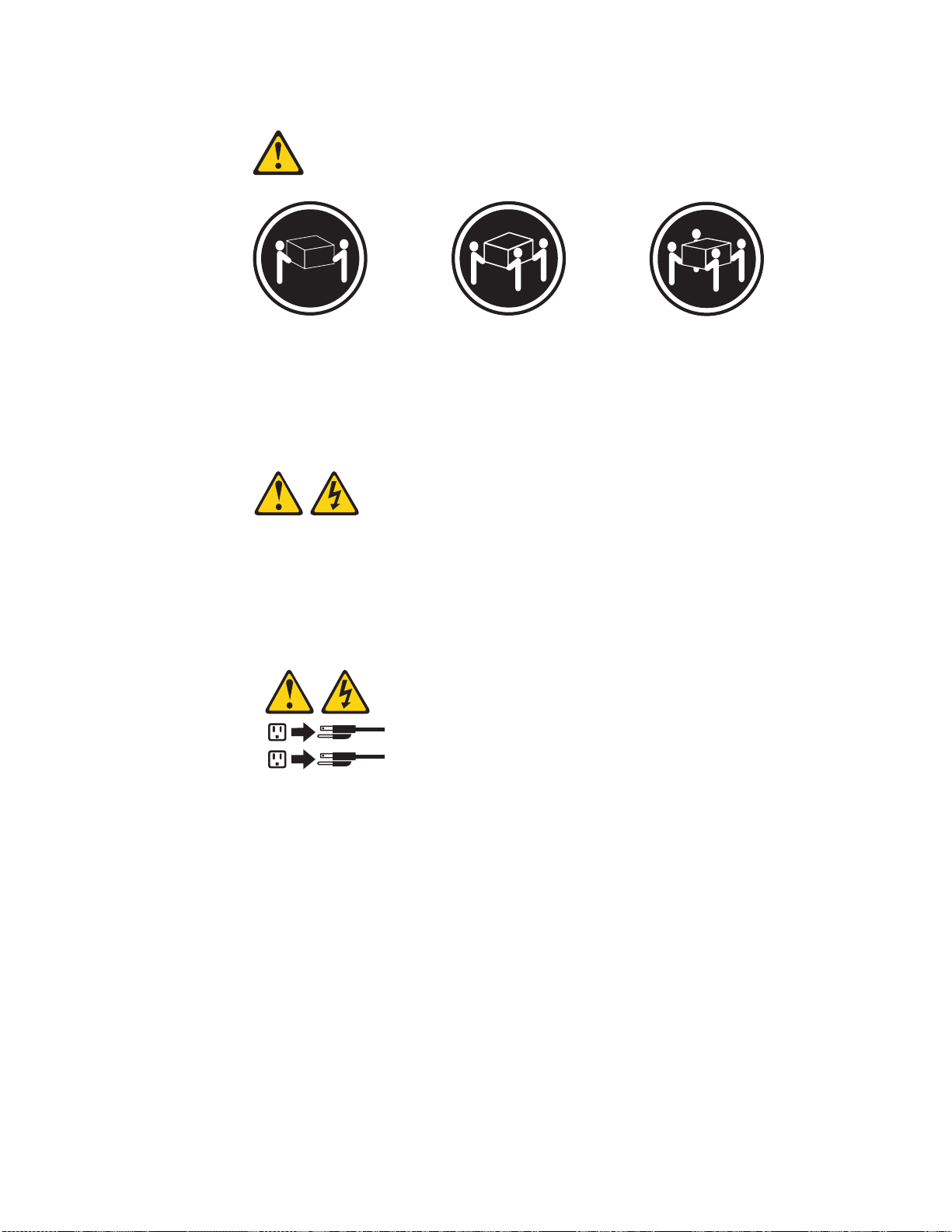
Statement 4:
≥ 18 kg (39.7 lb) ≥ 32 kg (70.5 lb) ≥ 55 kg (121.2 lb)
CAUTION:
Use safe practices when lifting.
Statement 5:
CAUTION:
The power control button on the device and the power switch on the power
supply do not turn off the electrical current supplied to the device. The device
also might have more than one power cord. To remove all electrical current
from the device, ensure that all power cords are disconnected from the power
source.
2
1
10 ThinkServer RD220 Types 3729, 3779, 3797, and 3798: Hardware Maintenance Manual
Page 19
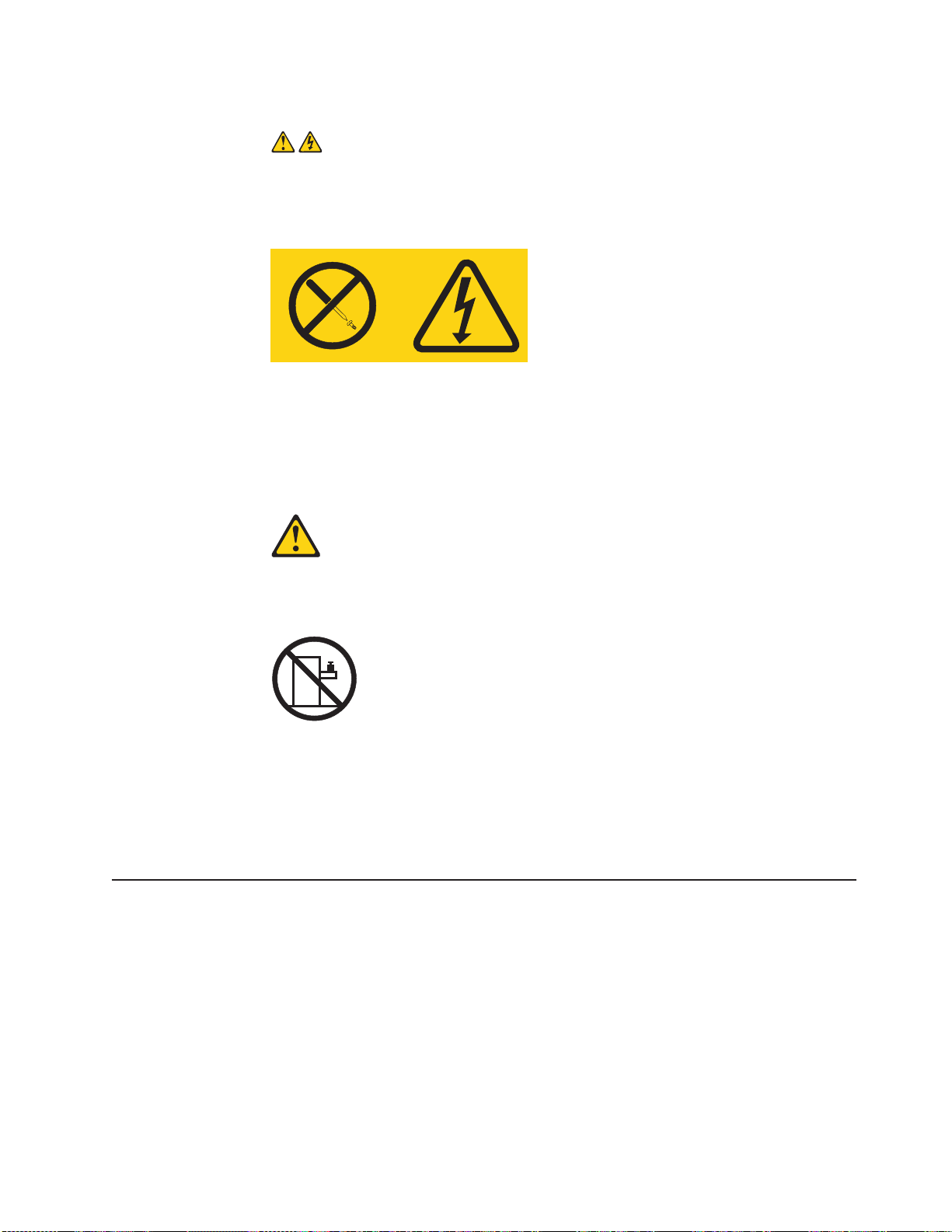
Statement 8:
CAUTION:
Never remove the cover on a power supply or any part that has the following
label attached.
Hazardous voltage, current, and energy levels are present inside any
component that has this label attached. There are no serviceable parts inside
these components. If you suspect a problem with one of these parts, contact
a service technician.
Statement 26:
CAUTION:
Do not place any object on top of rack-mounted devices.
Attention: This server is suitable for use on an IT power distribution system
whose maximum phase-to-phase voltage is 240 V under any distribution fault
condition.
Important: This product is not suitable for use with visual display workplace devices
according to Clause 2 of the German Ordinance for Work with Visual Display Units.
Installation guidelines
Before you install optional devices, read the following information:
v Read the safety information that begins on page 3, and the guidelines in this
section. This information will help you work safely.
v When you install your new server, take the opportunity to download and apply
the most recent firmware updates. This step will help to ensure that any known
issues are addressed and that your server is ready to function at maximum levels
of performance. To download firmware updates for your server, complete the
following steps:
1. Go to: http://www.lenovo.com/support.
2. Enter your product number (machine type and model number) or select
Servers and Storage from the Select your product list.
Chapter 2. Safety information 11
Page 20

3. From Family list, select ThinkServer, and click Continue.
4. Click Downloads and drivers to download firmware updates.
5. Click User’s guides and manuals for documentation.
v Before you install optional hardware, make sure that the server is working
correctly. Start the server, and make sure that the operating system starts, if an
operating system is installed, or that a 19990305 error code is displayed,
indicating that an operating system was not found but the server is otherwise
working correctly. If the server is not working correctly, refer to the “Diagnosing a
problem” on page 25 for diagnostic information.
v Observe good housekeeping in the area where you are working. Place removed
covers and other parts in a safe place.
v If you must start the server while the cover is removed, make sure that no one is
near the server and that no tools or other objects have been left inside the
server.
v Do not attempt to lift an object that you think is too heavy for you. If you have to
lift a heavy object, observe the following precautions:
– Make sure that you can stand safely without slipping.
– Distribute the weight of the object equally between your feet.
– Use a slow lifting force. Never move suddenly or twist when you lift a heavy
object.
– To avoid straining the muscles in your back, lift by standing or by pushing up
with your leg muscles.
v Make sure that you have an adequate number of properly grounded electrical
outlets for the server, monitor, and other devices.
v Back up all important data before you make changes to disk drives.
v Have a small flat-blade screwdriver available.
v To view the error LEDs on the system board and internal components, leave the
server connected to power.
v You do not have to turn off the server to install or replace hot-swap fans,
redundant hot-swap ac power supplies, or hot-plug Universal Serial Bus (USB)
devices. However, you must turn off the server before performing any steps that
involve removing or installing adapter cables or non-hot-swap optional devices or
components.
v Blue on a component indicates touch points, where you can grip the component
to remove it from or install it in the server, open or close a latch, and so on.
v Orange on a component or an orange label on or near a component indicates
that the component can be hot-swapped, which means that if the server and
operating system support hot-swap capability, you can remove or install the
component while the server is running. (Orange can also indicate touch points on
hot-swap components.) See the instructions for removing or installing a specific
hot-swap component for any additional procedures that you might have to
perform before you remove or install the component.
v When you are finished working on the server, reinstall all safety shields, guards,
labels, and ground wires.
v For a list of supported optional devices for the server, see http://www.lenovo.com/
thinkserver.
System reliability guidelines
To help ensure proper system cooling and system reliability, make sure that the
following requirements are met:
12 ThinkServer RD220 Types 3729, 3779, 3797, and 3798: Hardware Maintenance Manual
Page 21

v Each of the drive bays has a drive or a filler panel and electromagnetic
compatibility (EMC) shield installed in it.
v If the server has redundant power, each of the power-supply bays has a power
supply installed in it.
v There is adequate space around the server to allow the server cooling system to
work properly. Leave approximately 50 mm (2.0 in.) of open space around the
front and rear of the server. Do not place objects in front of the fans. For proper
cooling and airflow, replace the server cover before you turn on the server.
Operating the server for extended periods of time (more than 30 minutes) with
the server cover removed might damage server components.
v You have followed the cabling instructions that come with optional adapters.
v You have replaced a failed fan within 48 hours.
v You have replaced a hot-swap fan within 30 seconds of removal.
v You have replaced a hot-swap drive within 2 minutes of removal.
v You do not operate the server without the air baffles installed. Operating the
server without the air baffles might cause the microprocessors to overheat.
v Microprocessor 2 air baffle and DIMM air baffle are installed.
v The EasyLED diagnostics panel is not pulled out of the server.
Working inside the server with the power on
Attention: Static electricity that is released to internal server components when
the server is powered-on might cause the server to halt, which could result in the
loss of data. To avoid this potential problem, always use an electrostatic-discharge
wrist strap or other grounding system when working inside the server with the
power on.
The server supports hot-plug, hot-add, and hot-swap devices and is designed to
operate safely while it is turned on and the cover is removed. Follow these
guidelines when you work inside a server that is turned on:
v Avoid wearing loose-fitting clothing on your forearms. Button long-sleeved shirts
before working inside the server; do not wear cuff links while you are working
inside the server.
v Do not allow your necktie or scarf to hang inside the server.
v Remove jewelry, such as bracelets, necklaces, rings, and loose-fitting wrist
watches.
v Remove items from your shirt pocket, such as pens and pencils, that could fall
into the server as you lean over it.
v Avoid dropping any metallic objects, such as paper clips, hairpins, and screws,
into the server.
Handling static-sensitive devices
Attention: Static electricity can damage the server and other electronic devices.
To avoid damage, keep static-sensitive devices in their static-protective packages
until you are ready to install them.
To reduce the possibility of damage from electrostatic discharge, observe the
following precautions:
v Limit your movement. Movement can cause static electricity to build up around
you.
Chapter 2. Safety information 13
Page 22

v The use of a grounding system is recommended. For example, wear an
electrostatic-discharge wrist strap, if one is available. Always use an
electrostatic-discharge wrist strap or other grounding system when working inside
the server with the power on.
v Handle the device carefully, holding it by its edges or its frame.
v Do not touch solder joints, pins, or exposed circuitry.
v Do not leave the device where others can handle and damage it.
v While the device is still in its static-protective package, touch it to an unpainted
metal surface on the outside of the server for at least 2 seconds. This drains
static electricity from the package and from your body.
v Remove the device from its package and install it directly into the server without
setting down the device. If it is necessary to set down the device, put it back into
its static-protective package. Do not place the device on the server cover or on a
metal surface.
v Take additional care when handling devices during cold weather. Heating reduces
indoor humidity and increases static electricity.
14 ThinkServer RD220 Types 3729, 3779, 3797, and 3798: Hardware Maintenance Manual
Page 23

Chapter 3. General information
This chapter provides general information that applies to all machine types
supported by this publication.
Introduction
The four types of replaceable components are:
v Consumables: Purchase and replacement of consumables (components, such
as batteries and printer cartridges, that have depleting life) is your responsibility.
If Lenovo acquires or installs a consumable component at your request, you will
be charged for the service. For a list of consumable parts, see
http://www.lenovo.com/support.
v Tier 1 customer replaceable unit (CRU): Replacement of Tier 1 CRUs is your
responsibility. If Lenovo installs a Tier 1 CRU at your request, you will be charged
for the installation.
v Tier 2 customer replaceable unit: You may install a Tier 2 CRU yourself or
request Lenovo to install it, at no additional charge, under the type of warranty
service that is designated for your server.
v Field replaceable unit (FRU): FRUs must be installed only by trained service
technicians.
For a list of replaceable components for the server, go to:
http://www.lenovo.com/support
Features and technologies
The RD220 server offers the following features and technologies:
v UEFI-compliant server firmware
UEFI replaces the basic input/output system (BIOS) and defines a standard
interface between the operating system, platform firmware, and external devices.
UEFI-compliant servers are capable of booting UEFI-compliant operating
systems, BIOS-based operating systems, and BIOS-based adapters as well as
UEFI-compliant adapters.
Note: This server does not support DOS.
v Integrated Management Module
The Integrated Management Module (IMM) combines service processor
functions, video controller, and (when IMM Premium is installed) remote presence
function in a single chip. The IMM provides advanced service-processor control,
monitoring, and alerting function. If an environmental condition exceeds a
threshold or if a system component fails, the IMM lights LEDs to help you
diagnose the problem, records the error in the event log, and alerts you to the
problem. IMM Premium provides a virtual presence capability for remote server
management capabilities. The IMM provides remote server management through
industry-standard interfaces:
– Intelligent Platform Management Interface (IPMI) version 2.0
– Simple Network Management Protocol (SNMP) version 3
– Common Information Model (CIM)
– Web browser
v Remote presence capability and blue-screen capture
© Lenovo 2005, 2009. Portions © IBM Corp. 2007, 2008. 15
Page 24

IMM Premium is required to enable the remote presence and blue-screen
capture features. The remote presence feature provides the following functions:
– Remotely viewing video with graphics resolutions up to 1280 x 1024 at 75 Hz,
regardless of the system state
– Remotely accessing the server, using the keyboard and mouse from a remote
client
– Mapping the CD or DVD drive, diskette drive, and USB flash drive on a
remote client, and mapping ISO and diskette image files as virtual drives that
are available for use by the server
– Uploading a diskette image to the IMM memory and mapping it to the server
as a virtual drive
The blue-screen capture feature captures the video display contents before the
IMM restarts the server when the IMM detects an operating-system hang
condition. A system administrator can use the blue-screen capture to assist in
determining the cause of the hang condition.
®
v IBM
Advanced Settings Utility (ASU) program
Use this program as an alternative to the UEFI Setup Utility for modifying UEFI
settings. Use the ASU program online or out of band to modify UEFI settings
from the command line without the need to restart the server to access the UEFI
Setup Utility program.
v Preboot diagnostics programs
The preboot diagnostics programs are stored on the integrated USB memory. It
collects and analyzes system information to aid in diagnosing server problems.
The diagnostics programs collect the following information about the server:
– System configuration
– Network interfaces and settings
– Installed hardware
– EasyLED diagnostics status
– Service processor status and configuration
– Vital product data, firmware, and UEFI (formerly BIOS) configuration
– Hard disk drive health
– RAID controller configuration
– Event logs for RAID controllers and service processors
The diagnostics programs create a merged log that includes events from all
collected logs. The information is collected into a file that you can send to service
and support. Additionally, you can view the information locally through a
generated text report file. You can also copy the log to a removable media and
view the log from a Web browser.
For additional information about preboot diagnostics programs, see the Hardware
Maintenance Manual.
v EasyStartup DVD
The ThinkServer EasyStartup program guides you through the configuration of
the hardware, the RAID controller, and the installation of the operating system
and device drivers.
v EasyManage DVD
The EasyManage program helps you manage and administer your servers and
clients through remote problem notification as well as monitoring and alerting.
v Integrated network support
16 ThinkServer RD220 Types 3729, 3779, 3797, and 3798: Hardware Maintenance Manual
Page 25

The server comes with two integrated Broadcom Gigabit Ethernet controllers,
which support connection to a 10-Mbps, 100-Mbps, or 1000-Mbps network.
v Large data-storage and hot-swap capability
The server supports up to eight or twelve 2.5-inch hot-swap hard disk drives in
the hot-swap bays (depending on the model and optional devices installed). With
the hot-swap feature, you can add, remove, or replace hard disk drives without
turning off the server.
v EasyLED diagnostics
EasyLED diagnostics provides LEDs to help you diagnose problems. For more
information, see “EasyLED diagnostics panel” on page 46
v Memory mirroring
Memory mirroring improves the availability of memory by writing information to
the main memory and redundant locations in a mirrored pair of DIMMs.
v Large system-memory capacity
The memory bus supports up to 128 GB of system memory. The memory
controller supports error correcting code (ECC) for up to 16 industry-standard
PC3-10600R-999 (single-rank or dual-rank), 800, 1067, and 1333 MHz, DDR3
(third-generation double-data-rate), registered, synchronous dynamic random
access memory (SDRAM) dual inline memory modules (DIMMs).
v PCI adapter capabilities
The server supports up to four PCI interface slots. For more information, see
“Installing a PCI adapter” on page 180.
v Redundant connection
The addition of the optional Ethernet daughter card provides failover capability to
a redundant Ethernet connection with the applicable application installed. If a
problem occurs with the primary Ethernet connection and the optional Ethernet
daughter card is installed on the server, all Ethernet traffic that is associated with
the primary connection is automatically switched to the optional redundant
Ethernet daughter card connection. If the applicable device drivers are installed,
this switching occurs without data loss and without user intervention.
v Redundant cooling and power capabilities
The server supports three hot-swap fans, which provide redundant cooling.
Redundant cooling enables continued operation if one of the fans fails. The
server supports up to two 675-watt ac power supplies, which provide redundancy
and hot-swap capability for a typical configuration. If the maximum load on the
server is less than 675 watts and a problem occurs with one of the power
supplies, the other power supply can meet the power requirements.
v RAID support
The server supports an internal RAID SAS Controller, which is required for you to
use the hot-swap hard disk drives and to create redundant array of independent
disks (RAID) configurations.
v TCP/IP offload engine (TOE) support
The Ethernet controllers in the server support TOE, which is a technology that
offloads the TCP/IP flow from the microprocessors and I/O subsystem to increase
the speed of the TCP/IP flow. When an operating system that supports TOE is
running on the server and TOE is enabled, the server supports TOE operation.
See the operating-system documentation for information about enabling TOE.
Note: As of the date of this document, the Linux
support TOE.
®
operating system does not
Chapter 3. General information 17
Page 26

Specifications
The following information is a summary of the features and specifications of the
server. Depending on the server model, some features might not be available, or
some specifications might not apply.
Racks are marked in vertical increments of 4.45 cm (1.75 inches). Each increment
is referred to as a unit, or “U.” A 1-U-high device is 1.75 inches tall.
Notes:
1. Power consumption and heat output vary depending on the number and type of
optional features that are installed and the power-management optional features
that are in use.
2. The sound levels were measured in controlled acoustical environments
according to the procedures specified by the American National Standards
Institute (ANSI) S12.10 and ISO 7779 and are reported in accordance with ISO
9296. Actual sound-pressure levels in a given location might exceed the
average values stated because of room reflections and other nearby noise
sources. The declared sound-power levels indicate an upper limit, below which
a large number of computers will operate.
18 ThinkServer RD220 Types 3729, 3779, 3797, and 3798: Hardware Maintenance Manual
Page 27

Table 1. Features and specifications
Microprocessor:
v Dual Core or Quad Core Intel
with integrated memory controller and
Quick Path Interconnect (QPI)
architecture
v Designed for XBGA 1366 socket
v Scalable up to four cores
v 32 KB instruction cache, 32 KB data
cache, and 8 MB cache that is shared
among the cores
v Support for up to two microprocessors
v Support for Intel Extended Memory 64
Technology (EM64T)
Note:
v Use the Setup utility to determine the
type and speed of the microprocessors.
v For a list of supported microprocessors,
see http://www.lenovo.com/thinkserver
Memory:
v Sixteen DIMM connectors (eight per
microprocessor)
v Minimum: 1 GB DIMM per
microprocessor
v Maximum: 96 GB
v Type: Registered ECC double-data-rate
3 (DDR3) -800, -1066, and -1033
DIMMs only (PC3–10600R-999,
PC3–8500R-777)
v Sizes:
– 1 GB single-rank, 2 GB single-rank or
dual-rank, 4 GB dual-rank
(PC3–10600R-999)
– 8 GB quad-rank (PC3–8500R-777)
Drives:
CD/DVD: SATA interface 24x CD-RW/ 8x
DVD combination
Expansion bays:
Eight 2.5-inch SAS hot-swap hard disk
drive bays with option to add 4 more
2.5-inch SAS hot-swap hard disk drive
bays
Expansion slots:
v Two PCI Express riser cards with two
PCI Express x8 slots (x8 lanes) each,
standard
v Support for the following optional riser
cards:
– One PCI Express x16 slot (x16
lanes)
®
Xeon,
Hot-swap fans:
Three. Provide redundant cooling.
Hot-swap power supplies:
675 watts (100 - 240 V ac)
v Minimum: One
v Maximum: Two - provide redundant
power
Size (2 U):
v Height: 85.2 mm (3.346 in.)
v Depth: EIA flange to rear - 698 mm
(27.480 in.), Overall - 729 mm (28.701
in.)
v Width: With top cover - 443.6 mm
(17.465 in.), With front bezel - 482.0
mm (18.976 in.)
v Weight: approximately 21.09 kg (46.5
lb) to 29.03 kg (64 lb) depending upon
configuration
Integrated functions:
v Integrated Management Module (IMM),
which provides service processor
control and monitoring functions, video
controller, and (when the optional
virtual media key is installed) remote
keyboard, video, mouse, and remote
hard disk drive capabilities
v Dedicated or shared management
network connections
v Six-port Serial ATA (SATA) controller
v Serial over LAN (SOL) and serial
redirection over Telnet or Secure Shell
(SSH)
v One systems-management RJ-45 for
connection to a dedicated
systems-management network
v Support for remote management
presence through an optional virtual
media key
v One Broadcom dual-port 10/100/1000
Ethernet controller with TCP/IP Offload
Engine (TOE) support (second identical
Ethernet controller on an optional
internal adapter card)
v One serial port, shared with the
Integrated Management Module (IMM)
v Four Universal Serial Bus (USB) ports
(two on front, two on rear of server),
v2.0 supporting v1.1, plus one or more
dedicated internal USB ports on the
SAS riser card
v Two video ports (one on front and one
on rear of server)
Note: Maximum video resolution 1600
x 1200 at 60Hz
v One SATA tape connector, one USB
tape connector, and one tape power
connector on SAS riser card (some
models)
Note: In messages and documentation,
the term service processor refers to the
Integrated Management Module (IMM)
Video controller:
v Matrox G200 video on system board
v Compatible with SVGA and VGA
v 8 MB DDR2 SDRAM video memory
RAID controller:
v ServeRAID
™
-BR10i SAS/SATA Controller
that supports RAID levels 0, 1, 1E
(standard)
v Upgradeable to ServeRAID-MR10i
SAS/SATA Controller, which supports
RAID levels 0, 1, 5, 6, 10, 50, 60
Note: The RAID controllers are installed in
a PCI Express x8 mechanical slot (x4
electrical); however, the controllers run at x4
bandwidth.
Environment:
v Air temperature:
– Server on: 10° to 35°C (50.0° to
95.0°F); altitude: 0 to 3050 m (10006
ft). Decrease system temperature by
0.75°C for every 1000-foot increase in
altitude.
– Server off: 5° to 45°C (41.0° to
113.0°F); maximum altitude: 3050 m
(10006 ft)
– Shipment: -40° to +60°C (-40° to
140°F); maximum altitude: 2133 m
(7000 ft)
v Humidity:
– Server on: 20% to 80%
– Server off: 8% to 80%
– Shipment: 5% to 100%
Acoustical noise emissions:
v Declared sound power, idle: 6.3 bel
v Declared sound power, operating: 6.5 bel
Heat output:
Approximate heat output in British thermal
units (Btu) per hour:
v Minimum configuration: 307 Btu per hour
(194 watts)
v Maximum configuration: 2662 Btu per
hour (675 watts)
Electrical input with hot-swap ac power
supplies:
v Sine-wave input (50-60 Hz) required
v Input voltage range automatically selected
v Input voltage low range:
– Minimum: 100 V ac
– Maximum: 240 V ac
v Input voltage high range:
– Minimum: 200 V ac
– Maximum: 240 V ac
v Input kilovolt-amperes (kVA)
approximately:
– Minimum: 0.12 kVA
– Maximum: 0.78 kVA
Chapter 3. General information
19
Page 28

Software
EasyStartup
EasyManage
Lenovo provides software to help get your server up and running.
The ThinkServer EasyStartup program simplifies the process of your RAID
controller and installing supported Windows®and Linux operating systems and
device drivers on your server.TheEasyStartup program is provided with your server
on DVD. The DVD is self starting (bootable). The User Guide for the EasyStartup
program is on the DVD and can be accessed directly from the program’s interface.
The ThinkServer EasyManage Core Server provides centralized hardware and
software inventory management and secure automated system management
through a centralized console. The ThinkServer EasyManage Agent enables other
clients on the network to be managed by the centralized console. The ThinkServer
EasyManage Core Server is supported on 32-bit Windows Server 2003 and 32-bit
Windows Server 2008 products. TheThinkServer EasyManage Agent is supported
on 32-bit and 64-bit Windows, Red Hat, and SUSE operating systems.
20 ThinkServer RD220 Types 3729, 3779, 3797, and 3798: Hardware Maintenance Manual
Page 29

Chapter 4. General Checkout
You can solve many problems without outside assistance by following the
troubleshooting procedures in this Hardware Maintenance Manual and on the
Lenovo Web site. This document describes the diagnostic tests that you can
perform, troubleshooting procedures, and explanations of error messages and error
codes. The documentation that comes with your operating system and software
also contains troubleshooting information.
Diagnosing a problem
Before you contact Lenovo or an approved warranty service provider, follow these
procedures in the order in which they are presented to diagnose a problem with
your server:
1. Determine what has changed.
Determine whether any of the following items were added, removed, replaced,
or updated before the problem occurred:
v UEFI
v Device drivers
v Firmware
v Hardware components
v Software
If possible, return the server to the condition it was in before the problem
occurred.
2. Collect data.
Thorough data collection is necessary for diagnosing hardware and software
problems.
a. Document error codes and system-board LEDs.
v System error codes: See the Installation and User Guide for information
about a specific error code.
v See the Installation and User Guide for the location of the system-board
LEDs.
v Software or operating-system error codes: See the documentation for
the software or operating system for information about a specific error
code. See the manufacturer’s Web site for documentation.
v Light path diagnostics LEDs: See the Installation and User Guide for
information about LEDs that are lit.
b. Collect system data.
Run Dynamic System Analysis (DSA) Preboot diagnostics program to collect
information about the hardware, firmware, software, and operating system.
Have this information available when you contact Lenovo or an approved
warranty service provider. See http://www.lenovo.com/support for the
instructions to run the DSA Preboot program.
If you need to download the latest version of DSA Preboot, go to
http://www.lenovo.com/support or complete the following steps.
Note: Changes are made periodically to the Lenovo Web site. The actual
procedure might vary slightly from what is described in this
document.
1) Go to: http://www.lenovo.com/support.
© Lenovo 2005, 2009. Portions © IBM Corp. 2007, 2008. 21
Page 30

2) Enter your product number (machine type and model number) or select
Servers and Storage from the Select your product list.
3) From Family list, select ThinkServer, and click Continue.
4) Click Downloads and drivers to download firmware updates.
For information about DSA command-line options, go to:
http://www.lenovo.com/support
3. Follow the problem-resolution procedures.
The four problem-resolution procedures are presented in the order in which they
are most likely to solve your problem. Follow these procedures in the order in
which they are presented:
a. Check for and apply code updates.
Most problems that appear to be caused by faulty hardware are actually
caused by the UEFI firmware (formerly BIOS firmware), device firmware, or
device drivers that are not at the latest levels.
1) Determine the existing code levels.
In DSA, click Firmware/VPD to view system firmware levels, or click
Software to view operating-system levels.
2) Download and install updates of code that is not at the latest level.
Important: Some cluster solutions require specific code levels or
coordinated code updates. If the device is part of a cluster solution,
verify that the latest level of code is supported for the cluster solution
before you update the code.
To display a list of available updates for your server, go to
http://www.lenovo.com/thinkserver or complete the following steps.
Note: Changes are made periodically to the Lenovo Web site. The
actual procedure might vary slightly from what is described in this
document.
a) Go to: http://www.lenovo.com/support.
b) Enter your product number (machine type and model number) or
select Servers and Storage from the Select your product list.
c) From Family list, select ThinkServer, and click Continue.
d) Click Downloads and drivers to download firmware updates.
When you click an update, an information page is displayed, including a
list of the problems that the update fixes. Review this list for your
specific problem; however, even if your problem is not listed, installing
the update might solve the problem.
b. Check for and correct an incorrect configuration.
If the server is incorrectly configured, a system function can fail to work
when you enable it; if you make an incorrect change to the server
configuration, a system function that has been enabled can stop working.
1) Make sure that all installed hardware and software are supported.
See http://www.lenovo.com/support to verify that the server supports the
installed operating system, optional devices, and software levels. If any
hardware or software component is not supported, uninstall it to
determine whether it is causing the problem. You must remove
nonsupported hardware before you contact Lenovo or an approved
warranty service provider for support.
2) Make sure that the server, operating system, and software are
installed and configured correctly.
22 ThinkServer RD220 Types 3729, 3779, 3797, and 3798: Hardware Maintenance Manual
Page 31

Many configuration problems are caused by loose power or signal
cables or incorrectly seated adapters. You might be able to solve the
problem by turning off the server, reconnecting cables, reseating
adapters, and turning the server back on. See the Installation and User
Guide for the instructions to perform the checkout procedures.
If the problem is associated with a specific function (for example, if a
RAID hard disk drive is marked offline in the RAID array), see the
documentation for the associated controller and management or
controlling software to verify that the controller is correctly configured.
Problem determination information is available for many devices such as
RAID and network adapters.
For problems with operating systems or Lenovo software or devices,
complete the following steps.
Note: Changes are made periodically to the Lenovo Web site. The
actual procedure might vary slightly from what is described in this
document.
a) Enter your product number (machine type and model number) or
select Servers and Storage from the Select your product list.
b) From Family list, select ThinkServer, and click Continue.
c) Click Downloads and drivers to download firmware updates.
d) Click User’s guides and manuals for documentation.
c. Lenovo Hints and Tips document known problems and suggested
solutions.
To search for hints and tips, complete the following steps (the actual
procedure might vary slightly from what is described in this document):
Note: Changes are made periodically to the Lenovo Web site.
1) Go to http://www.lenovo.com/support.
2) Select Servers and Storage from the Product list.
3) From the Family list, select ThinkServer RD210 and click Continue.
4) Click on Hints and Tips.
d. Check for and replace defective hardware.
If a hardware component is not operating within specifications, it can cause
unpredictable results. Most hardware failures are reported as error codes in
a system or operating-system log. Hardware errors are also indicated by
light path diagnostics LEDs. See the Installation and User Guide for more
information.
Troubleshooting procedures are also provided on the Lenovo Web site. A
single problem might cause multiple symptoms. Follow the diagnostic
procedure for the most obvious symptom. If that procedure does not
diagnose the problem, use the procedure for another symptom, if possible.
To locate troubleshooting procedures for your server, complete the following
steps.
Note: Changes are made periodically to the Lenovo Web site. The actual
procedure might vary slightly from what is described in this
document.
1) Go to: http://www.lenovo.com/support.
2) Enter your product number (machine type and model number) or select
Servers and Storage from the Select your product list.
Chapter 4. General Checkout 23
Page 32

3) From Family list, select ThinkServer, and click Continue.
4) Click on Troubleshooting.
For more troubleshooting information, see the Installation and User Guide.
If the problem remains, contact Lenovo or an approved warranty service
provider for assistance with additional problem determination and possible
hardware replacement. To open an online service request, go to
http://www.lenovo.com/support. Be prepared to provide information about
any error codes and collected data.
Undocumented problems
If you have completed the diagnostic procedure and the problem remains, the
problem might not have been previously identified by Lenovo. After you have
verified that all code is at the latest level, all hardware and software configurations
are valid, and no light path diagnostics LEDs or log entries indicate a hardware
component failure, contact Lenovo or an approved warranty service provider for
assistance. To open an online service request, go to http://www.lenovo.com/support.
Be prepared to provide information about any error codes and collected data and
the problem determination procedures that you have used.
24 ThinkServer RD220 Types 3729, 3779, 3797, and 3798: Hardware Maintenance Manual
Page 33

Chapter 5. Diagnostics
Diagnosing a problem
Before you contact Lenovo or an approved warranty service provider, follow these
procedures in the order in which they are presented to diagnose a problem with
your server:
1. Determine what has changed.
Determine whether any of the following items were added, removed, replaced,
or updated before the problem occurred:
v UEFI
v Device drivers
v Firmware
v Hardware components
v Software
If possible, return the server to the condition it was in before the problem
occurred.
2. Collect data.
Thorough data collection is necessary for diagnosing hardware and software
problems.
a. Document error codes and system-board LEDs.
v System error codes: See the Installation and User Guide for information
about a specific error code.
v See the Installation and User Guide for the location of the system-board
LEDs.
v Software or operating-system error codes: See the documentation for
the software or operating system for information about a specific error
code. See the manufacturer’s Web site for documentation.
v Light path diagnostics LEDs: See the Installation and User Guide for
information about LEDs that are lit.
b. Collect system data.
Run Dynamic System Analysis (DSA) Preboot diagnostics program to collect
information about the hardware, firmware, software, and operating system.
Have this information available when you contact Lenovo or an approved
warranty service provider. See http://www.lenovo.com/support for the
instructions to run the DSA Preboot program.
If you need to download the latest version of DSA Preboot, go to
http://www.lenovo.com/support or complete the following steps.
Note: Changes are made periodically to the Lenovo Web site. The actual
procedure might vary slightly from what is described in this
document.
1) Go to: http://www.lenovo.com/support.
2) Enter your product number (machine type and model number) or select
Servers and Storage from the Select your product list.
3) From Family list, select ThinkServer, and click Continue.
4) Click Downloads and drivers to download firmware updates.
For information about DSA command-line options, go to:
http://www.lenovo.com/support
© Lenovo 2005, 2009. Portions © IBM Corp. 2007, 2008. 25
Page 34

3. Follow the problem-resolution procedures.
The four problem-resolution procedures are presented in the order in which they
are most likely to solve your problem. Follow these procedures in the order in
which they are presented:
a. Check for and apply code updates.
Most problems that appear to be caused by faulty hardware are actually
caused by the UEFI firmware (formerly BIOS firmware), device firmware, or
device drivers that are not at the latest levels.
1) Determine the existing code levels.
In DSA, click Firmware/VPD to view system firmware levels, or click
Software to view operating-system levels.
2) Download and install updates of code that is not at the latest level.
Important: Some cluster solutions require specific code levels or
coordinated code updates. If the device is part of a cluster solution,
verify that the latest level of code is supported for the cluster solution
before you update the code.
To display a list of available updates for your server, go to
http://www.lenovo.com/thinkserver or complete the following steps.
Note: Changes are made periodically to the Lenovo Web site. The
actual procedure might vary slightly from what is described in this
document.
a) Go to: http://www.lenovo.com/support.
b) Enter your product number (machine type and model number) or
select Servers and Storage from the Select your product list.
c) From Family list, select ThinkServer, and click Continue.
d) Click Downloads and drivers to download firmware updates.
When you click an update, an information page is displayed, including a
list of the problems that the update fixes. Review this list for your
specific problem; however, even if your problem is not listed, installing
the update might solve the problem.
b. Check for and correct an incorrect configuration.
If the server is incorrectly configured, a system function can fail to work
when you enable it; if you make an incorrect change to the server
configuration, a system function that has been enabled can stop working.
1) Make sure that all installed hardware and software are supported.
See http://www.lenovo.com/support to verify that the server supports the
installed operating system, optional devices, and software levels. If any
hardware or software component is not supported, uninstall it to
determine whether it is causing the problem. You must remove
nonsupported hardware before you contact Lenovo or an approved
warranty service provider for support.
2) Make sure that the server, operating system, and software are
installed and configured correctly.
Many configuration problems are caused by loose power or signal
cables or incorrectly seated adapters. You might be able to solve the
problem by turning off the server, reconnecting cables, reseating
adapters, and turning the server back on. See the Installation and User
Guide for the instructions to perform the checkout procedures.
If the problem is associated with a specific function (for example, if a
RAID hard disk drive is marked offline in the RAID array), see the
26 ThinkServer RD220 Types 3729, 3779, 3797, and 3798: Hardware Maintenance Manual
Page 35

documentation for the associated controller and management or
controlling software to verify that the controller is correctly configured.
Problem determination information is available for many devices such as
RAID and network adapters.
For problems with operating systems or Lenovo software or devices,
complete the following steps.
Note: Changes are made periodically to the Lenovo Web site. The
actual procedure might vary slightly from what is described in this
document.
a) Enter your product number (machine type and model number) or
select Servers and Storage from the Select your product list.
b) From Family list, select ThinkServer, and click Continue.
c) Click Downloads and drivers to download firmware updates.
d) Click User’s guides and manuals for documentation.
c. Lenovo Hints and Tips document known problems and suggested
solutions.
To search for hints and tips, complete the following steps (the actual
procedure might vary slightly from what is described in this document):
Note: Changes are made periodically to the Lenovo Web site.
1) Go to http://www.lenovo.com/support.
2) Select Servers and Storage from the Product list.
3) From the Family list, select ThinkServer RD210 and click Continue.
4) Click on Hints and Tips.
d. Check for and replace defective hardware.
If a hardware component is not operating within specifications, it can cause
unpredictable results. Most hardware failures are reported as error codes in
a system or operating-system log. Hardware errors are also indicated by
light path diagnostics LEDs. See the Installation and User Guide for more
information.
Troubleshooting procedures are also provided on the Lenovo Web site. A
single problem might cause multiple symptoms. Follow the diagnostic
procedure for the most obvious symptom. If that procedure does not
diagnose the problem, use the procedure for another symptom, if possible.
To locate troubleshooting procedures for your server, complete the following
steps.
Note: Changes are made periodically to the Lenovo Web site. The actual
procedure might vary slightly from what is described in this
document.
1) Go to: http://www.lenovo.com/support.
2) Enter your product number (machine type and model number) or select
Servers and Storage from the Select your product list.
3) From Family list, select ThinkServer, and click Continue.
4) Click on Troubleshooting.
For more troubleshooting information, see the Installation and User Guide.
If the problem remains, contact Lenovo or an approved warranty service
provider for assistance with additional problem determination and possible
Chapter 5. Diagnostics 27
Page 36

hardware replacement. To open an online service request, go to
http://www.lenovo.com/support. Be prepared to provide information about
any error codes and collected data.
Undocumented problems
If you have completed the diagnostic procedure and the problem remains, the
problem might not have been previously identified by Lenovo. After you have
verified that all code is at the latest level, all hardware and software configurations
are valid, and no light path diagnostics LEDs or log entries indicate a hardware
component failure, contact Lenovo or an approved warranty service provider for
assistance. To open an online service request, go to http://www.lenovo.com/support.
Be prepared to provide information about any error codes and collected data and
the problem determination procedures that you have used.
Diagnostic tools
The following tools are available to help you diagnose and solve hardware-related
problems:
v Troubleshooting tables
These tables list problem symptoms and actions to correct the problems.
v Light path diagnostics
Use the light path diagnostics to diagnose system errors quickly.
v Preboot Dynamic System Analysis (DSA) diagnostic programs
The Preboot DSA diagnostic programs provide problem isolation, configuration
analysis, and error log collection. The diagnostic programs are the primary
method of testing the major components of the server and are stored in
integrated USB memory. The diagnostic programs collect the following
information about the server:
– System configuration
– Network interfaces and settings
– Installed hardware
– Light path diagnostics status
– Service processor status and configuration
– Vital product data, firmware, and UEFI configuration
– Hard disk drive health
– RAID controller configuration
– ServeRAID controller and service processor event logs, including:
- System error logs
- Temperature, voltage, and fan speed information
- Tape drive presence and read/write test results
- Systems management analysis and reporting technology (SMART) data
- USB information
- monitor configuration information
- PCI slot information
The diagnostic programs create a merged log that includes events from all
collected logs. The information is collected into a file that you can send to the
Lenovo Support Center. Additionally, you can view the server information locally
through a generated text report file. You can also copy the log to removable
media and view the log from a Web browser. See “Running the diagnostic
programs” on page 54 for more information.
v Checkpoint codes
28 ThinkServer RD220 Types 3729, 3779, 3797, and 3798: Hardware Maintenance Manual
Page 37

POST
Checkpoint codes track the progress of POST routines at system startup or
reset. Checkpoint codes are shown on the checkpoint display, which is on the
light path diagnostics panel. See “Checkpoint codes” on page 41 for more
information.
When you turn on the server, it performs a series of tests to check the operation of
the server components and some optional devices in the server. This series of tests
is called the power-on self-test, or POST.
If a power-on password is set, you must type the password and press Enter, when
prompted, for POST to run.
Chapter 5. Diagnostics 29
Page 38

Error logs
The POST error log contains the three most recent error codes and messages that
were generated during POST. The RMM system event log contains monitored
events, such as a threshold that is reached or a device that fails. The system
event/error log contains messages that were generated during POST and all system
status messages from the service processor.
The following illustration shows an example of a RMM system event log entry.
---------------------------------------------------------Get Next Entry
Get Previous Entry
Clear BMC SEL
Entry Number= 00005 / 00011
Record ID= 0005
Record Type= 02
Timestamp= 2005/01/25 16:15:17
Entry Details: Generator ID= 0020
RMM System Event Log
Sensor Type= 04
Assertion Event
Fan
Threshold
Lower Non-critical - going high
Sensor Number= 40
Event Direction/Type= 01
Event Data= 52 00 1A
The RMM system event log is limited in size. When the log is full, new entries will
not overwrite existing entries; therefore, you must periodically clear the RMM
system event log through the Server Configuration and Boot Management program.
When you are troubleshooting an error, be sure to clear the RMM system event log
so that you can find current errors more easily.
Entries that are written to the RMM system event log during the early phase of
POST show an incorrect date and time as the default time stamp; however, the
date and time are corrected as POST continues.
Each system event/error log entry appears on its own page. To move from one
entry to the next, use the up-arrow and down-arrow keys.
If you view the RMM system event log through the Web interface of the optional
virtual media key, the messages can be translated.
You can view the contents of the POST error log, the RMM system event log, and
the system event/error log from the Server Configuration and Boot Management
program. You can view the contents of the RMM system event log also from the
diagnostic programs.
When you are troubleshooting PCI slots, note that the error logs report the PCI
buses numerically. The numerical assignments vary depending on the configuration.
You can check the assignments by running the Server Configuration and Boot
Management program (see the Installation and Users Guide for more information).
30 ThinkServer RD220 Types 3729, 3779, 3797, and 3798: Hardware Maintenance Manual
Page 39

Viewing error logs from the Server Configuration and Boot Management program
For complete information about using the Server Configuration and Boot
Management program, see the Installation and User’s Guide.
To view the error logs, complete the following steps:
1. Turn on the server.
2. When the prompt Press F1 to enter Setup appears, press F1. If you have set
both a power-on password and an administrator password, you must type the
administrator password to view the error logs.
3. Use one of the following procedures:
v To view the POST error log, select Event/Error Logs, and then select POST
Error Log.
v To view the BMC system event log, select Advanced Setup --> Baseboard
Management Controller (BMC) Setting --> System Event Log.
v To view the combined system event/error log and POST error log, select
Event/Error logs, and then select System Event/Error Log.
Viewing the RMM system event log from the diagnostic programs
The RMM system event log contains the same information, whether it is viewed
from the Server Configuration and Boot Management program or from the
diagnostic programs.
For information about using the diagnostic programs, see “Running the diagnostic
programs” on page 54.
To view the RMM system event log, complete the following steps:
1. If the server is running, turn off the server and all attached devices.
2. Turn on all attached devices; then, turn on the server.
3. When the prompt F2 for Diagnostics appears, press F2. If you have set both a
power-on password and an administrator password, you must type the
administrator password to run the diagnostic programs.
4. From the top of the screen, select Hardware Info.
5. From the list, select RMM Log.
Clearing the error logs
For complete information about using the Server Configuration and Boot
Management program, see the Installation and User’s Guide.
To clear the error logs, complete the following steps:
1. Turn on the server.
2. When the prompt Press F1 to enter Setup appears, press F1. If you have set
both a power-on password and an administrator password, you must type the
administrator password to view the error logs.
3. Use one of the following procedures:
v To clear the RMM system event log, select Advanced Setup --> Baseboard
Management Controller (BMC) Setting--> BMC System Event Log. Select
Clear BMC SEL.
v To clear the system event/error log, if one is present, or the POST error log,
select Event/Error Logs, and then select Post Error Log or System
Chapter 5. Diagnostics 31
Page 40

Event/Error Log. When any log entry is displayed, press Enter (Clear xxxx
log is highlighted on each entry page, where xxxx is the name of the log that
you are viewing).
Note: The POST error log is automatically cleared with each system restart.
POST error codes
The following table describes the POST error codes and suggested actions to
correct the detected problems.
v Follow the suggested actions in the order in which they are listed in the Action column until the problem
is solved.
v See Chapter 7, “Parts listing, ThinkServer RD220 Type 3729, 3779, 3797, and 3798,” on page 231 to
determine which components are customer replaceable units (CRU) and which components are field
replaceable units (FRU).
v If an action step is preceded by “(Trained service technician only),” that step must be performed only by a
trained service technician.
Error code Description Action
062 Three consecutive boot failures using the
default configuration.
101, 102 System and processor error. (Trained service technician only) Replace the system
106 System and processor error. (Trained service technician only) Replace the system
151 Real-time clock error.
1. Run the Server Configuration and Boot
Management program, save the configuration,
and restart the server.
2. Update the system firmware to the latest level.
(see the information in Installation and User
Guide).
3. Reseat the following components, one at a time,
in the order shown, restarting the server each
time:
a. Battery
b. (Trained service technician only)
Microprocessor
4. Replace the following components one at a time,
in the order shown, restarting the server each
time:
a. Battery
b. (Trained service technician only)
Microprocessor
c. (Trained service technician only) System
board
board.
board.
1. Reseat the battery.
2. Clear CMOS memory. See “System-board
switches and jumpers” on page 152 for
information about how to clear CMOS memory.
3. Replace the following components one at a time,
in the order shown, restarting the server each
time:
a. Battery
b. (Trained service technician only) System
board
32 ThinkServer RD220 Types 3729, 3779, 3797, and 3798: Hardware Maintenance Manual
Page 41

v Follow the suggested actions in the order in which they are listed in the Action column until the problem
is solved.
v See Chapter 7, “Parts listing, ThinkServer RD220 Type 3729, 3779, 3797, and 3798,” on page 231 to
determine which components are customer replaceable units (CRU) and which components are field
replaceable units (FRU).
v If an action step is preceded by “(Trained service technician only),” that step must be performed only by a
trained service technician.
Error code Description Action
161 Real-time clock battery error.
1. Reseat the battery.
2. Clear CMOS memory. See “System-board
switches and jumpers” on page 152 for
information about how to clear CMOS memory.
3. Replace the following components one at a time,
in the order shown, restarting the server each
time:
a. Battery
b. (Trained service technician only) System
board
162 Device configuration error.
1. Run the Server Configuration and Boot
Management program, select Load Default
Settings, and save the settings.
2. Reseat the following components, one at a time,
in the order shown, restarting the server each
time:
a. Battery
b. Failing device (if the device is a FRU, then it
must be reseated by a trained service
technician only)
3. Replace the following components one at a time,
in the order shown, restarting the server each
time:
a. Battery
b. Failing device (if the device is a FRU, then it
must be replaced by a trained service
technician only)
c. (Trained service technician only) System
board
163 Real-time clock error. (time of day not set)
1. Run the Server Configuration and Boot
Management program, select Load Default
Settings, make sure that the date and time are
correct, and save the settings.
2. Reseat the battery.
3. Clear CMOS memory. See “System-board
switches and jumpers” on page 152 for
information about how to clear CMOS memory.
4. Replace the following components one at a time,
in the order shown, restarting the server each
time:
a. Battery
b. (Trained service technician only) System
board
Chapter 5. Diagnostics 33
Page 42

v Follow the suggested actions in the order in which they are listed in the Action column until the problem
is solved.
v See Chapter 7, “Parts listing, ThinkServer RD220 Type 3729, 3779, 3797, and 3798,” on page 231 to
determine which components are customer replaceable units (CRU) and which components are field
replaceable units (FRU).
v If an action step is preceded by “(Trained service technician only),” that step must be performed only by a
trained service technician.
Error code Description Action
184 Power-on password damaged.
187 VPD serial number not set.
189 An attempt was made to access the server
with an incorrect password.
289 A DIMM has been disabled by the user or
by the system.
301 Keyboard or keyboard controller error.
1. Restart the server and enter the administrator
password; then, run the Server Configuration and
Boot Management program, select Load Default
Settings, and save the settings.
2. Reseat the battery.
3. Clear CMOS memory. See “System-board
switches and jumpers” on page 152 for
information about how to clear CMOS memory.
4. Replace the following components one at a time,
in the order shown, restarting the server each
time:
a. Battery
b. (Trained service technician only) System
board
1. Run the Server Configuration and Boot
Management program, set the serial number, and
save the configuration.
2. (Trained service technician only) Replace the
system board.
Restart the server and enter the administrator
password; then, run the Server Configuration and
Boot Management program and change the power-on
password.
1. If the DIMM was disabled by the user, run the
Server Configuration and Boot Management
program and enable the DIMM.
2. Make sure that the DIMM is installed correctly
(see “Installing a DIMM” on page 192).
3. Reseat the DIMM.
4. Replace the DIMM.
1. Reseat the keyboard cable in the USB connector.
2. Move the keyboard cable to a different USB
connector.
3. Replace the following components one at a time,
in the order shown, restarting the server each
time:
a. Keyboard
b. (Only if the problem occurred with a front USB
connector) Internal USB cable.
c. (Trained service technician only) System
board
34 ThinkServer RD220 Types 3729, 3779, 3797, and 3798: Hardware Maintenance Manual
Page 43

v Follow the suggested actions in the order in which they are listed in the Action column until the problem
is solved.
v See Chapter 7, “Parts listing, ThinkServer RD220 Type 3729, 3779, 3797, and 3798,” on page 231 to
determine which components are customer replaceable units (CRU) and which components are field
replaceable units (FRU).
v If an action step is preceded by “(Trained service technician only),” that step must be performed only by a
trained service technician.
Error code Description Action
303 Keyboard controller error.
1. Reseat the keyboard cable in the USB connector.
2. Replace the following components one at a time,
in the order shown, restarting the server each
time:
a. Keyboard
b. (Trained service technician only) System
board
1600 Service processor not functioning.
1. (Trained service technician only) Replace the
system board.
178x Fixed disk error.
Note: x is the drive that has the error
1. Run the hard disk drive diagnostics tests on drive
x.
2. Reseat the following components:
a. Hard disk drive
b. Cable from the system board to the backplane
3. Replace the following components one at a time,
in the order shown, restarting the server each
time:
a. Hard disk drive
b. Cable from the system board to the backplane
c. Hard disk drive backplane
d. (Trained service technician only) System
board
1800 Unavailable PCI hardware interrupt.
1. Run the Server Configuration and Boot
Management program and adjust the adapter
settings.
2. Remove each adapter one at a time, restarting
the server each time, until the problem is isolated.
Chapter 5. Diagnostics 35
Page 44

v Follow the suggested actions in the order in which they are listed in the Action column until the problem
is solved.
v See Chapter 7, “Parts listing, ThinkServer RD220 Type 3729, 3779, 3797, and 3798,” on page 231 to
determine which components are customer replaceable units (CRU) and which components are field
replaceable units (FRU).
v If an action step is preceded by “(Trained service technician only),” that step must be performed only by a
trained service technician.
Error code Description Action
1801 An adapter has requested memory
resources that are not available
Note: The server can allocate only 128 KB
of optional-device load space (option ROM
space); error code 1801 occurs if the load
space required by an optional-device ROM
when loading exceeds the available
(remaining) load space. Changing the
optional-device load order can cause an
optional-device ROM that requires more
load space to load sooner, when more load
space is available; the other optional-device
ROMs might still fit in the remaining load
space. With some optional devices, some or
all of the load space used is released after
the ROM code loads and initializes the
optional device.
1805 PCI option ROM checksum error.
1810 PCI error.
1. If possible, rearrange the order of the adapters in
the PCI slots, to change the load order of the
optional-device ROM code.
2. Server Configuration and Boot Management
program, select Startup Options, and change the
boot sequence, to change the load order of the
optional-device ROM code.
3. Run the Server Configuration and Boot
Management program and disable some other
resources, if their functions are not being used, to
make more space available.
v Select Startup Options then Planar Ethernet
(PXE/DHCP) to disable the onboard Ethernet
controller ROM.
v Select Advanced Functions, then PCI Bus
Control, then PCI ROM Control Execution to
disable the ROM of adapters in the PCI slots.
v Select Devices and I/O Ports to disable any of
the onboard devices.
4. If the problem remains, replace the following
components one at a time, in the order shown,
restarting the server each time:
a. Each adapter
b. (Trained service technician only) System
board
1. Remove the failing adapter.
2. Reseat each adapter (all PCI slots).
3. Reseat the riser card.
4. Replace the following components one at a time,
in the order shown, restarting the server each
time:
a. Each adapter
b. Riser card
c. (Trained service technician only) System
board
1. Reseat all adapters.
2. Reseat the riser card.
3. Remove both adapters from the riser card.
4. Replace the following components one at a time,
in the order shown, restarting the server each
time:
a. Riser card
b. (Trained service technician only) System
board
36 ThinkServer RD220 Types 3729, 3779, 3797, and 3798: Hardware Maintenance Manual
Page 45

v Follow the suggested actions in the order in which they are listed in the Action column until the problem
is solved.
v See Chapter 7, “Parts listing, ThinkServer RD220 Type 3729, 3779, 3797, and 3798,” on page 231 to
determine which components are customer replaceable units (CRU) and which components are field
replaceable units (FRU).
v If an action step is preceded by “(Trained service technician only),” that step must be performed only by a
trained service technician.
Error code Description Action
1962 A hard disk drive does not contain a valid
boot sector.
1. Make sure that a startable operating system is
installed.
2. Run the hard disk drive diagnostic tests.
3. Reseat the following components:
a. Hard disk drive
b. Hard disk drive backplane cable
4. Replace the following components one at a time,
in the order shown, restarting the server each
time:
a. Cable from hard disk drive backplane to
system board
b. Hard disk drive
c. Hard disk drive backplane
d. (Trained service technician only) System
board
8603 Pointing-device error.
1. Reseat the pointing device.
2. Replace the following components one at a time,
in the order shown, restarting the server each
time:
a. Pointing device
b. (Trained service technician only) System
board
00012000 Processor machine check error.
1. (Trained service technician only) Reseat the
microprocessor.
2. Replace the following components one at a time,
in the order shown, restarting the server each
time:
a. (Trained service technician only)
Microprocessor
b. (Trained service technician only) System
board
00019701 Processor 1 failed BIST.
1. (Trained service technician only) Reseat the
microprocessor.
2. Replace the following components one at a time,
in the order shown, restarting the server each
time:
a. (Trained service technician only)
Microprocessor
b. (Trained service technician only) System
board
Chapter 5. Diagnostics 37
Page 46

v Follow the suggested actions in the order in which they are listed in the Action column until the problem
is solved.
v See Chapter 7, “Parts listing, ThinkServer RD220 Type 3729, 3779, 3797, and 3798,” on page 231 to
determine which components are customer replaceable units (CRU) and which components are field
replaceable units (FRU).
v If an action step is preceded by “(Trained service technician only),” that step must be performed only by a
trained service technician.
Error code Description Action
01298001 No update data for processor 1.
01298101 Bad update data for processor 1.
I9990301 Hard disk drive boot sector error.
I9990305 Operating system not found. Run the Server Configuration and Boot Management
I9990650 Power has been restored.
1. Update the UEFI code again.
2. (Trained service technician only) Replace the
microprocessor.
1. Update the UEFI code again.
2. (Trained service technician only) Replace the
microprocessor.
1. Reseat the following components:
a. Hard disk drive
b. Hard disk drive backplane cable
2. Replace the following components one at a time,
in the order shown, restarting the server each
time:
a. Hard disk drive backplane cable
b. Hard disk drive
c. Hard disk drive backplane
d. (Trained service technician only) System
board
program to make sure that a bootable operating
system is installed on one or more devices that are
listed in the boot order.
1. Check the power cables.
2. Check for interruption of the power supply.
38 ThinkServer RD220 Types 3729, 3779, 3797, and 3798: Hardware Maintenance Manual
Page 47

Checkout procedure
The checkout procedure is the sequence of tasks that you should follow to
diagnose a problem in the server.
About the checkout procedure
Before performing the checkout procedure for diagnosing hardware problems,
review the following information:
v Read the safety information that begins on page 3.
v The diagnostic programs provide the primary methods of testing the major
components of the server, such as the system board, Ethernet controller,
keyboard, mouse (pointing device), serial ports, and hard disk drives. You can
also use them to test some external devices. If you are not sure whether a
problem is caused by the hardware or by the software, you can use the
diagnostic programs to confirm that the hardware is working correctly.
v When you run the diagnostic programs, a single problem might cause more than
one error message. When this happens, correct the cause of the first error
message. The other error messages usually will not occur the next time you run
the diagnostic programs.
Exception: If there are multiple error codes or LEDs that indicate a
microprocessor error, the error might be in the microprocessor or in
the microprocessor socket. See “Solving Microprocessor problems”
on page 144 for information about diagnosing microprocessor
problems.
v Before running the diagnostic programs, you must determine whether the failing
server is part of a shared hard disk drive cluster (two or more servers sharing
external storage devices). If it is part of a cluster, you can run all diagnostic
programs except the ones that test the storage unit (that is, a hard disk drive in
the storage unit) or the storage adapter that is attached to the storage unit. The
failing server might be part of a cluster if any of the following conditions is true:
– You have identified the failing server as part of a cluster (two or more servers
sharing external storage devices).
– One or more external storage units are attached to the failing server and at
least one of the attached storage units is also attached to another server or
unidentifiable device.
– One or more servers are located near the failing server.
Important: If the server is part of a shared hard disk drive cluster, run one test
at a time. Do not run any suite of tests, such as “quick” or “normal”
tests, because this might enable the hard disk drive diagnostic tests.
v If the server is halted and a POST error code is displayed, see “Error logs” on
page 30.
v For information about power-supply problems, see “Solving power problems” on
page 143.
v For intermittent problems, check the error log; see “Error logs” on page 30 and
“Diagnostic programs, messages, and error codes” on page 54.
Chapter 5. Diagnostics 39
Page 48

Performing the checkout procedure
To perform the checkout procedure, complete the following steps:
1. Is the server part of a cluster?
v No: Go to step 2.
v Yes: Shut down all failing servers that are related to the cluster. Go to step 2.
2. Complete the following steps:
a. Check the power supply LEDs, see “Power-supply LEDs” on page 50.
b. Turn off the server and all external devices.
c. Check all internal and external devices for compatibility at
http://www.ibm.com/servers/eserver/serverproven/compat/us/.
d. Make sure the server is cabled correctly.
e. Check all cables and power cords.
f. Set all display controls to the middle positions.
g. Turn on all external devices.
h. Turn on the server.
i. Check the system-error LED on the operator information panel. If it is
flashing, check the light path diagnostics LEDs.
j. Check for the following results:
v Successful completion of POST (see “POST” on page 29 for more
information).
v Successful completion of startup, which is indicated by a readable display
of the operating-system desktop.
40 ThinkServer RD220 Types 3729, 3779, 3797, and 3798: Hardware Maintenance Manual
Page 49

Checkpoint codes
A checkpoint code is a value produced by the UEFI indicating the point at which the
system stopped during startup and Power-On Self Test (POST); it does not provide
error codes or suggest replacement components. These codes may be used for
more in-depth troubleshooting by Lenovo support.
Checkpoint codes are shown on the checkpoint code display on the light path
diagnostics panel (see “Light path diagnostics LEDs” on page 44 for the location of
the display area). By using the checkpoint display, you do not have to wait for the
video to initialize each time you restart the server.
The following table describes the microprocessor checkpoint codes.
Table 2. Microprocessor Checkpoint Codes
Diagnostic Code Description
0010001 Microprocessor disabled
0010002 Microprocessor not supported
0010004 Microprocessor invalid
0011000 Invalid microprocessor type
0011002 Microprocessor mismatch
0011004 Microprocessor failed BIST
001100A Microcode update failed
There are two types of checkpoint codes: field programmable gate array (FPGA)
hardware checkpoint codes and UEFI checkpoint codes. The UEFI checkpoint
codes might change because of code sequence and timing changes or when the
UEFI code is updated. See http://www.lenovo.com/supportfor checkpoint code
information.
Light path diagnostics
Light path diagnostics is a system of LEDs on various external and internal
components of the server. When an error occurs, LEDs are lit throughout the
server. By viewing the LEDs in a particular order, you can often identify the source
of the error.
When LEDs are lit to indicate an error, they remain lit when the server is turned off,
provided that the server is still connected to power and the power supply is
operating correctly.
Before working inside the server to view light path diagnostics LEDs, read the
safety information that begins on page 3.
If an error occurs, view the light path diagnostics LEDs in the following order:
1. Look at the operator information panel on the front of the server.
v If the information LED is lit, it indicates that information about a suboptimal
condition in the server is available in the RMM system event log or in the
system event/error log.
v If the system-error LED is lit, it indicates that an error has occurred; go to
step 2 on page 42.
The following illustration shows the operator information panel.
Chapter 5. Diagnostics 41
Page 50

2. To view the light path diagnostics panel, slide the latch to the left on the front of
the operator information panel and pull the panel forward. This reveals the light
path diagnostics panel. Lit LEDs on this panel indicate the type of error that has
occurred.
The following illustration shows the light path diagnostics panel.
Note any LEDs that are lit, and then push the light path diagnostics panel back
into the server.
Look at the system service label on the top of the server, which gives an
overview of internal components that correspond to the LEDs on the light path
diagnostics panel. This information and the information in “Light path diagnostics
LEDs” on page 44 can often provide enough information to diagnose the error.
3. Remove the server cover and look inside the server for lit LEDs. A lit LED on or
beside a component identifies the component that is causing the error.
The following illustration shows the LEDs on the system board.
42 ThinkServer RD220 Types 3729, 3779, 3797, and 3798: Hardware Maintenance Manual
Page 51

12v channel error LEDs indicate an overcurrent condition. Table 4 on page 143
identifies the components associated with each power channel, and the order in
which to troubleshoot the components.
The following illustration shows the LEDs on the riser card.
PCI Slot 2 error LED
PCI Slot 1 error LED
Chapter 5. Diagnostics 43
Page 52

Remind button
You can use the remind button on the light path diagnostics panel to put the
system-error LED on the operator information panel into Remind mode. When you
press the remind button, you acknowledge the error but indicate that you will not
take immediate action. The system-error LED flashes while it is in Remind mode
and stays in Remind mode until one of the following conditions occurs:
v All known errors are corrected.
v The server is restarted.
v A new error occurs, causing the system-error LED to be lit again.
Light path diagnostics LEDs
The following table describes the LEDs on the light path diagnostics panel and
suggested actions to correct the detected problems.
Note: Check the system event/error log and BMC system event log for additional
information before replacing a FRU.
LED Problem Action
None, but
the
System
Error LED
is lit.
OVER
SPEC
LOG An error message has been written to
LINK Reserved.
PS A power supply has failed.
PCI An error has occurred on a PCI bus or
SP The service processor (the RMM) has
An error has occurred and cannot be
diagnosed, or the RMM has failed. The
error is not represented by a light path
diagnostics LED.
The server was shut down due to a
power supply overload condition on one
of the power channels. The power
supplies are using more power than
their maximum rating.
the system log
on the system board. An additional LED
will be lit next to a failing PCI slot.
failed.
Use the Server Configuration and Boot Management program
to check the system error log for information about the error.
1. If any of the 12v power channel error LEDs (A, B, C, D, E,
2. Check the power supply LEDs for an error indication (AC
3. Remove optional devices from the server.
See the system log for details about the error.
1. Check the power supply LEDs for an error indication (AC
2. Make sure that the failing power supply is correctly seated.
3. Replace the failed power supply.
1. Check the LEDs on the PCI slots to identify the component
2. Check the system-error log for information about the error.
3. If you cannot isolate the failing adapter through the LEDs
4. Call for service.
1. Remove power from the server; then, reconnect the server
2. Update the firmware on the RMM.
3. Call for service
or 240v AUX) on the system board are lit also, see the
entries about power-channel error LEDs in “Solving power
problems” on page 143. (See “Power-supply LEDs” on page
50 for the location of the power channel error LEDs.)
LED and DC LED are not both lit, or the information LED is
lit). Replace a failing power supply.
LED and DC LED are not both lit).
that is causing the error.
and the information in the system-error log, remove one
adapter at a time from the failing PCI bus, and restart the
server after each adapter is removed.
to power and restart the server.
44 ThinkServer RD220 Types 3729, 3779, 3797, and 3798: Hardware Maintenance Manual
Page 53

LED Problem Action
FAN A fan has failed, is operating too slowly,
or has been removed. The TEMP LED
might also be lit.
Replace the failing fan, which is indicated by a lit LED near the
fan connector on the system board.
Note: If an LED that is next to an unused fan connector on the
system board is lit, a PCI riser-card assembly might be missing:
replace the PCI riser-card assembly. Both PCI riser-card
assemblies must always be present.
TEMP The system temperature has exceeded
a threshold level. A failing fan can
cause the TEMP LED to be lit.
1. Check the error log to identify where the over-temperature
condition was measured. If a fan has failed, replace it.
2. Make sure that the room temperature is not too high. See
“Features and technologies” on page 15 for temperature
information.
3. Make sure that the air vents are not blocked.
4. Call for service.
MEM A memory error has occurred. Replace the failing DIMM, which is indicated by the lit LED on
the system board.
NMI A non-maskable interrupt has occurred,
Check the system-error log for information about the error.
or the NMI button has been pressed.
CNFG A hardware configuration error has
occurred.
1. Check the microprocessors that were just installed to make
sure that they are compatible with each other (see the
Installation and User Guide).
2. (Trained service technician only) Replace an incompatible
microprocessor.
3. Check the system-error logs for information about the error.
Replace any components that are indicated.
CPU A microprocessor has failed.
1. Make sure that the failing microprocessor, which is indicated
by a lit LED on the system board, is installed correctly. See
“Installing a microprocessor and heat sink” on page 218 for
information about installing a microprocessor.
2. Make sure that the ServeRAID SAS controller is installed
and correctly seated. Make sure that the battery for the
ServeRAID SAS controller is installed correctly.
3. Call for service.
VRM Reserved.
DASD A hard disk drive error has occurred. A
hard disk drive has failed or is missing.
1. Check the LEDs on the hard disk drives and replace the
indicated drive.
2. Reseat the hard disk drive backplane cables.
3. Remove and reinstall the hard disk drive backplanes.
4. Call for service.
RAID A RAID controller error has occurred.
1. Make sure that a RAID controller is installed.
Note: The server will not start without a RAID controller
installed.
2. Check the system-error log for information about the error.
3. Reseat the RAID controller.
Chapter 5. Diagnostics 45
Page 54

LED Problem Action
BRD An error has occurred on the system
board.
1. Check the LEDs on the system board to identify the
2. Check the system-error log for information about the error.
3. Replace any failed or missing replaceable components,
4. If a voltage regulator has failed, replace the system board.
EasyLED diagnostics panel
The EasyLED diagnostics panel is located on the top of the operator information
panel.
To access the diagnostics panel, slide the blue release button on the operator
information panel to the left. Pull forward on the operator panel until the hinge of the
panel is free of the server chassis. Then pull down on the operator panel, so that
you can view the diagnostics panel information.
component that is causing the error. The BRD LED can be
lit for the following conditions:
v Battery
v Missing PCI riser-card assembly
v Failed voltage regulator
such as the battery or PCI riser-card assembly.
1 Operator information panel
2 Diagnostic LEDs
3 Release latch
The following illustration shows the controls and LEDs on the diagnostics panel.
Note: Diagnostics LEDs remain lit only while the server is connected to power.
46 ThinkServer RD220 Types 3729, 3779, 3797, and 3798: Hardware Maintenance Manual
Page 55

A checkpoint code (See checkpoint code display 1) is either a byte or a word
value produced by UEFI and sent to the I/O port indicating the point at which the
system stopped during the boot block and Power-On Self Test (POST). It does not
provide error codes or suggest replacement components. These codes can be used
by Lenovo Support for more in depth troubleshooting.
v Remind button: This button places the system-error LED on the front panel into
Remind mode. In Remind mode, the system-error LED flashes once every 2
seconds until the problem is corrected, the system is restarted, or a new problem
occurs.
By placing the system-error LED indicator in Remind mode, you acknowledge
that you are aware of the last failure but will not take immediate action to correct
the problem. The remind function is controlled by the IMM.
v NMI button: Press this button to force a nonmaskable interrupt to the
microprocessor, if directed to do so by service and support.
v Check-point code display: During POST, this display indicates server firmware
progress. The display does not provide error codes or suggest components to be
replaced. Checkpoint codes can be used by Lenovo Support for further
troubleshooting. See the Hardware Maintenance Manual for more information
about checkpoint codes.
There are two types of checkpoint codes: field programmable gate array (FPGA)
hardware checkpoint codes and UEFI checkpoint codes. The UEFI checkpoint
codes might change because of code sequence and timing changes or when the
server firmware is updated.
v Reset button: Press this button to reset the server and run the power-on
self-test (POST). You might have to use a pen or the end of a straightened paper
clip to press the button. The reset button is in the lower right-hand corner of the
diagnostics panel.
For more information about EasyLED diagnostics, see the Hardware Maintenance
Manual.
The following table lists the LEDs on the EasyLED diagnostics panel and suggested
actions to solve the detected problems.
v Follow the suggested actions in the order in which they are listed in the Action column until the problem
is solved.
v See the parts listing in the Hardware Maintenance Manual to determine which components are customer
replaceable units (CRU) and which components are field replaceable units (FRU).
v If an action step is preceded by “(Trained service technician only),” that step must be performed only by a
trained service technician.
LED Description Action
None, but
the
systemerror LED
is lit.
An error has occurred and cannot be
diagnosed, or the IMM has failed. The
error is not represented by an EasyLED
diagnostics LED.
Use the Setup utility to check the system-event log for
information about the error.
Chapter 5. Diagnostics 47
Page 56

v Follow the suggested actions in the order in which they are listed in the Action column until the problem
is solved.
v See the parts listing in the Hardware Maintenance Manual to determine which components are customer
replaceable units (CRU) and which components are field replaceable units (FRU).
v If an action step is preceded by “(Trained service technician only),” that step must be performed only by a
trained service technician.
LED Description Action
OVER
SPEC
The server was shut down due to a
power-supply overload condition on one
of the power channels. The power
supplies are using more power than the
maximum rating.
1. If any of the 12v power channel error LEDs (A, B, C, D, E,
or AUX) on the system board are lit also, see “Solving
power problems” on page 143. (See “Power-supply LEDs”
on page 50 for the location of the power channel error
LEDs.)
2. Check the power supply LEDs for an error indication (AC
LED and DC LED are not both lit, or the power-supply error
LED is lit). Swap power supplies 1 and 2 with each other.
v If the error follows the power supply, replace the failed
power supply.
v If the error remains with the power bay, (trained service
technician only) replace the system board.
3. Remove optional devices from the server.
LOG An error message has been written to
the system-event log
Check the IMM system event log and the system-error log for
information about the error. Replace any components that are
identified in the error logs.
LINK Reserved.
PS A power supply has failed.
1. Check the power supply LEDs for an error indication (AC
LED and DC LED are not both lit). See “Power-supply
LEDs” on page 50 for more information.
2. Make sure that the failing power supply is correctly seated.
3. Replace the failed power supply.
PCI An error has occurred on a PCI bus or
on the system board. An additional LED
will be lit next to a failing PCI slot.
1. Check the LEDs on the PCI slots to identify the component
that is causing the error.
2. Check the system-event log for information about the error.
3. If you cannot isolate the failing adapter through the LEDs
and the information in the system-event log, remove one
adapter at a time from the failing PCI bus, and restart the
server after each adapter is removed.
4. Call for service.
SP
™
The service processor (the IMM) has
failed.
1. Remove power from the server; then, reconnect the server
to power and restart the server.
2. Update the firmware on the IMM.
3. Call for service
FAN A fan has failed, is operating too slowly,
or has been removed. The TEMP LED
Replace the failing fan, which is indicated by a lit LED near the
fan connector on the system board.
might also be lit.
TEMP The system temperature has exceeded
a threshold level. A failing fan can
cause the TEMP LED to be lit.
1. Check the error log to identify where the over-temperature
condition was measured. If a fan has failed, replace it.
2. Make sure that the room temperature is not too high. See
Table 1 on page 19 for temperature information.
3. Make sure that the air vents are not blocked.
4. Call for service.
48 ThinkServer RD220 Types 3729, 3779, 3797, and 3798: Hardware Maintenance Manual
Page 57

v Follow the suggested actions in the order in which they are listed in the Action column until the problem
is solved.
v See the parts listing in the Hardware Maintenance Manual to determine which components are customer
replaceable units (CRU) and which components are field replaceable units (FRU).
v If an action step is preceded by “(Trained service technician only),” that step must be performed only by a
trained service technician.
LED Description Action
MEM When only the MEM LED is lit, a
memory error has occurred.
When the MEM and CNFG LEDs are
lit, the memory configuration is not
valid.
1. Determine whether the CNFG LED is also lit. If it is, run the
memory test exerciser to isolate the problem (see Hardware
Maintenance Manual for more information).
a. If the test reports that a memory error has occurred,
replace the failing DIMM, which is indicated by the lit
LED on the system board.
b. If the test reports the memory configuration is invalid,
repopulate the DIMMs to a supported configuration.
2. If the CNFG LED is not lit, one of the following conditions
should be present:
v The server did not boot and a failing DIMM LED is lit.
a. Check for a PFA log event in the System Event Log
(SEL)
b. Reseat the DIMM.
c. If the problem remains, move the DIMM to a different
slot.
1) If the DIMM LED lights up on the system board
that corresponds to this new DIMM socket,
replace the DIMM.
2) If the DIMM LED lights up on the system board
that corresponds to the original DIMM socket,
replace the system board (trained service
technician only).
v The server booted and the failing DIMM is disabled and
the LED is lit.
a. If the LEDs are lit by two DIMMs, check the System
Event Log for PFA on one of the DIMMs, then replace
that DIMM. Otherwise, replace both DIMMs.
b. If the LED is lit by only one DIMM, replace that
DIMM.
c. Re-enable the DIMM sockets in the server firmware
settings.
NMI A nonmaskable interrupt has occurred,
Check the system-event log for information about the error.
or the NMI button has been pressed.
CNFG A hardware configuration error has
occurred. (This LED is used with the
MEM and the CPU LEDs.)
Chapter 5. Diagnostics 49
Page 58

v Follow the suggested actions in the order in which they are listed in the Action column until the problem
is solved.
v See the parts listing in the Hardware Maintenance Manual to determine which components are customer
replaceable units (CRU) and which components are field replaceable units (FRU).
v If an action step is preceded by “(Trained service technician only),” that step must be performed only by a
trained service technician.
LED Description Action
CPU When only the CPU LED is lit, a
microprocessor has failed.
When the CPU and CNFG LEDs are lit,
the microprocessor configuration is not
valid.
VRM Reserved.
DASD A hard disk drive error has occurred. A
hard disk drive has failed or is missing.
RAID Reserved
BRD An error has occurred on the system
board.
1. Determine whether the CNFG LED is also lit. If the CNFG
LED is not lit, a microprocessor has failed.
a. Make sure that the failing microprocessor, which is
indicated by a lit LED on the system board, is installed
correctly. See the Hardware Maintenance Manual for
information about installing a microprocessor.
b. If the failure remains, call service.
2. If the CNFG LED is lit, then an invalid microprocessor
configuration has occurred.
a. Make sure that the microprocessors are compatible with
each other. They must match in speed and cache size.
To compare the microprocessor information, run the
Setup utility and select System Information, then select
System Summary, and then select Processor Details.
b. (Trained service technician only) Replace an
incompatible microprocessor.
c. If the failure remains, call for service.
1. Check the LEDs on the hard disk drives for the drive with a
lit status LED and reseat the hard disk drive.
2. Reseat the hard disk drive backplane.
3. Remove and reinstall the hard disk drive backplanes.
4. Replace the hard disk drive backplane for the failing drive or
drives.
5. Call for service.
1. Check the LEDs on the system board to identify the
component that is causing the error.
2. Check the system-event log for information about the error.
3. Replace any failed or missing replaceable components,
such as the battery or PCI riser-card assembly.
4. If a voltage regulator has failed, replace the system board.
Power-supply LEDs
The following minimum configuration is required for the DC LED on the power
supply to be lit:
v Power supply
v Power cord
The following minimum configuration is required for the server to start:
v One microprocessor
v One 1 GB DIMM per microprocessor on the system board
v One power supply
50 ThinkServer RD220 Types 3729, 3779, 3797, and 3798: Hardware Maintenance Manual
Page 59

The following illustration shows the locations of the power-supply LEDs.
The following table describes the problems that are indicated by various
combinations of the ac power-supply LEDs and the power-on LED on the operator
information panel and suggested actions to correct the detected problems.
Chapter 5. Diagnostics 51
Page 60

v Follow the suggested actions in the order in which they are listed in the Action column until the problem
is solved.
v See Chapter 7, “Parts listing, ThinkServer RD220 Type 3729, 3779, 3797, and 3798,” on page 231 to
determine which components are customer replaceable units (CRU) and which components are field
replaceable units (FRU).
v If an action step is preceded by “(Trained service technician only),” that step must be performed only by a
trained service technician.
Power-supply LEDs
Description Action NotesAC DC Error
Off Off Off No ac power to
the server or a
problem with the
ac power source.
Off Off On No ac power to
the server or a
problem with the
ac power source
and the power
supply had
detected an
internal problem.
Off On Off Faulty power
supply
Off On On Faulty power
supply
On Off Off Power supply not
fully seated,
faulty system
board, or faulty
power supply
On Off On Faulty power
supply
On On Off Normal operation
On On On Power supply is
faulty but still
operational
1. Check the ac power to the server.
2. Make sure that the power cord is
connected to a functioning power
source.
1. Replace the power supply.
2. Make sure that the power cord is
connected to a functioning power
source.
Replace the power supply.
Replace the power supply.
1. Reseat the power supply.
2. If the 240V Failure LED on the system
board is lit, have the system board
replaced.
3. If the 240V Failure LED on the system
board is not lit, replace the power
supply.
Replace the power supply.
Replace the power supply.
Normal condition
when no ac power is
present.
This only happens
when a second
power supply is
providing power to
the server.
Typically indicates a
power supply is not
fully seated.
Server power features
When the server is connected to a power source but is not turned on, the operating
system does not run, and all core logic except for the Integrated Management
Module (IMM) is shut down; however, the server can respond to requests from the
IMM, such as a remote request to turn on the server. The power-on LED flashes to
indicate that the server is connected to power but is not turned on.
Turning on the server
Approximately 3 minutes after the server is connected to power, the power-control
button becomes active, and one or more fans might start running to provide cooling
while the server is connected to power. You can turn on the server and start the
52 ThinkServer RD220 Types 3729, 3779, 3797, and 3798: Hardware Maintenance Manual
Page 61

operating system by pressing the power-control button. If a power failure occurs
while the server is turned on, the server will restart automatically when power is
restored.
For 32-bit operating systems only: Some memory is reserved for various system
resources and is unavailable to the operating system. The amount of memory that
is reserved for system resources depends on the operating system, the
configuration of the server, and the configured PCI options.
Turning off the server
When you turn off the server and leave it connected to power, the server can
respond to requests from the IMM, such as a remote request to turn on the server.
While the server remains connected to power, one or more fans might continue to
run. To remove all power from the server, you must disconnect it from the power
source.
Important: To view the error LEDs on the system board, leave the server
connected to a power source.
Some operating systems require an orderly shutdown before you turn off the server.
See your operating-system documentation for information about shutting down the
operating system.
Statement 5:
CAUTION:
The power control button on the device and the power switch on the power
supply do not turn off the electrical current supplied to the device. The device
also might have more than one power cord. To remove all electrical current
from the device, ensure that all power cords are disconnected from the power
source.
2
1
The server can be turned off in any of the following ways:
v You can turn off the server from the operating system, if your operating system
supports this feature. After an orderly shutdown of the operating system, the
server will be turned off automatically.
v You can press the power-control button to start an orderly shutdown of the
operating system and turn off the server, if your operating system supports this
feature.
v If the operating system stops functioning, you can press and hold the
power-control button for more than 4 seconds to turn off the server.
v The IMM can turn off the server as an automatic response to a critical system
failure.
v You can turn off the server through a request from the IMM.
Chapter 5. Diagnostics 53
Page 62

Diagnostic programs, messages, and error codes
The diagnostic programs are the primary method of testing the major components
of the server. As you run the diagnostic programs, text messages are displayed on
the screen and are saved in the test log. A diagnostic text message indicates that a
problem has been detected and provides the action you should take as a result of
the text message.
Make sure that the server has the latest version of the diagnostic programs. To
download the latest version, complete the following steps.
Note: Changes are made periodically to the Lenovo Web site. The actual
procedure might vary slightly from what is described in this document.
1. Go to: http://www.lenovo.com/support.
2. Enter your product number (machine type and model number) or select Servers
and Storage from the Select your product list.
3. From Family list, select ThinkServer, and click Continue.
4. Click Downloads and drivers to download firmware updates.
Utilities are available to reset and update the code on the integrated USB flash
device, if the diagnostic partition becomes damaged and does not start the
diagnostic programs. For more information and to download the utilities, go to
http://www.lenovo.com/support.
Running the diagnostic programs
To run the diagnostic programs, complete the following steps:
1. If the server is running, turn off the server and all attached devices.
2. Turn on all attached devices; then, turn on the server.
3. When the prompt Press F2 for Dynamic System Analysis (DSA) is displayed,
press F2.
Note: The Preboot DSA diagnostic program might appear to be unresponsive
for an unusual length of time when you start the program. This is normal
operation while the program loads.
4. Optionally, select Exit to DSA to exit from the stand-alone memory diagnostic
program.
Note: After you exit from the stand-alone memory diagnostic environment, you
must restart the server to access the stand-alone memory diagnostic
environment again.
5. Select gui to display the graphical user interface, or select cmd to display the
DSA interactive menu.
6. Follow the instructions on the screen to select the diagnostic test to run.
If the diagnostic programs do not detect any hardware errors but the problem
remains during normal server operations, a software error might be the cause. If
you suspect a software problem, see the information that comes with your software.
A single problem might cause more than one error message. When this happens,
correct the cause of the first error message. The other error messages usually will
not occur the next time you run the diagnostic programs.
54 ThinkServer RD220 Types 3729, 3779, 3797, and 3798: Hardware Maintenance Manual
Page 63

Exception: If there are multiple error codes or diagnostics LEDs that indicate a
microprocessor error, the error might be in a microprocessor or in a
microprocessor socket. See “Solving Microprocessor problems” on
page 144 for information about diagnosing microprocessor problems.
If the server stops during testing and you cannot continue, restart the server and try
running the diagnostic programs again. If the problem remains, replace the
component that was being tested when the server stopped.
Diagnostic text messages
Diagnostic text messages are displayed while the tests are running. A diagnostic
text message contains one of the following results:
Passed: The test was completed without any errors.
Failed: The test detected an error.
Aborted: The test could not proceed because of the server configuration.
Additional information concerning test failures is available in the extended
diagnostic results for each test.
Viewing the test log
To view the test log when the tests are completed, type the view command in the
DSA interactive menu, or select Diagnostic Event Log in the graphical user
interface. To transfer DSA collections to an external USB device, type the copy
command in the DSA interactive menu.
Diagnostic messages
The following table describes the messages that the diagnostic programs might
generate and suggested actions to correct the detected problems. Follow the
suggested actions in the order in which they are listed in the action column.
Chapter 5. Diagnostics 55
Page 64

Table 3. DSA diagnostic messages
v Follow the suggested actions in the order in which they are listed in the Action column until the problem
is solved.
v See Chapter 7, “Parts listing, ThinkServer RD220 Type 3729, 3779, 3797, and 3798,” on page 231 to
determine which components are customer replaceable units (CRU) and which components are field
replaceable units (FRU).
v If an action step is preceded by “(Trained service technician only),” that step must be performed only by a
trained service technician.
Message
number Component Test State Description Action
089-801-xxx CPU CPU
Stress Test
089-801-xxx
(continued)
Aborted Internal
program error.
1. Turn off and restart the system.
2. Make sure that the DSA code is at the
latest level. For the latest level of DSA
code, go to http://www.ibm.com/
support/docview.wss?uid=psg1SERVDSA.
3. Run the test again.
4. Make sure that the system firmware is
at the latest level. The installed
firmware level is shown in the DSA
event log in the Firmware/VPD section
for this component. For the latest level
of firmware, go to
http://www.ibm.com/support/
docview.wss?uid=psg1 MIGR-4JTS2T
and select your system to display a
matrix of available firmware.
5. Run the test again.
6. Turn off and restart the system if
necessary to recover from a hung
state.
7. Run the test again.
(Continued on the next page)
8. Replace the following components one
at a time, in the order shown, and run
this test again to determine whether
the problem has been solved:
a. (Trained service technician only)
Microprocessor ( see “Removing a
microprocessor and heat sink” on
page 216 and “Installing a
microprocessor and heat sink” on
page 218).
9. If the failure remains, collect the data
from the DSA event log and send it to
Lenovo service. For information about
contacting and sending data to
Lenovo, see http://www.ibm.com/
support/
docview.wss?uid=psg1SERVCALL.
56 ThinkServer RD220 Types 3729, 3779, 3797, and 3798: Hardware Maintenance Manual
Page 65

Table 3. DSA diagnostic messages (continued)
v Follow the suggested actions in the order in which they are listed in the Action column until the problem
is solved.
v See Chapter 7, “Parts listing, ThinkServer RD220 Type 3729, 3779, 3797, and 3798,” on page 231 to
determine which components are customer replaceable units (CRU) and which components are field
replaceable units (FRU).
v If an action step is preceded by “(Trained service technician only),” that step must be performed only by a
trained service technician.
Message
number Component Test State Description Action
089-802-xxx CPU CPU
Stress Test
Aborted System
resource
availability
error.
1. Turn off and restart the system.
2. Make sure that the DSA code is at the
latest level. For the latest level of DSA
code, go to http://www.ibm.com/
support/docview.wss?uid=psg1SERVDSA.
3. Run the test again.
4. Make sure that the system firmware is
at the latest level. The installed
firmware level is shown in the DSA
event log in the Firmware/VPD section
for this component. For the latest level
of firmware, go to
http://www.ibm.com/support/
docview.wss?uid=psg1 MIGR-4JTS2T
and select your system to display a
matrix of available firmware.
5. Run the test again.
6. Turn off and restart the system if
necessary to recover from a hung
state.
7. Run the test again.
8. Make sure that the system firmware is
at the latest level. The installed
firmware level is shown in the DSA
event log in the Firmware/VPD section
for this component. For the latest level
of firmware, go to
http://www.ibm.com/support/
docview.wss?uid=psg1 MIGR-4JTS2T
and select your system to display a
matrix of available firmware.
9. Run the test again.
Chapter 5. Diagnostics 57
Page 66

Table 3. DSA diagnostic messages (continued)
v Follow the suggested actions in the order in which they are listed in the Action column until the problem
is solved.
v See Chapter 7, “Parts listing, ThinkServer RD220 Type 3729, 3779, 3797, and 3798,” on page 231 to
determine which components are customer replaceable units (CRU) and which components are field
replaceable units (FRU).
v If an action step is preceded by “(Trained service technician only),” that step must be performed only by a
trained service technician.
Message
number Component Test State Description Action
089-802-xxx CPU CPU
Stress Test
089-901-xxx CPU CPU
Stress Test
Aborted System
resource
availability
error.
Failed Test failure.
10. Replace the following components
one at a time, in the order shown,
and run this test again to determine
whether the problem has been
solved:
a. (Trained service technician only)
Microprocessor ( see “Removing
a microprocessor and heat sink”
on page 216 and “Installing a
microprocessor and heat sink” on
page 218).
11. If the failure remains, collect the data
from the DSA event log and send it to
IBM Service. For information about
contacting and sending data to IBM
Service, see http://www.ibm.com/
support/
docview.wss?uid=psg1SERVCALL.
1. Turn off and restart the system if
necessary to recover from a hung
state.
2. Make sure that the DSA code is at the
latest level. For the latest level of DSA
code, go to http://www.ibm.com/
support/docview.wss?uid=psg1SERVDSA.
3. Run the test again.
4. Make sure that the system firmware is
at the latest level. The installed
firmware level is shown in the DSA
event log in the Firmware/VPD section
for this component. For the latest level
of firmware, go to
http://www.ibm.com/support/
docview.wss?uid=psg1 MIGR-4JTS2T
and select your system to display a
matrix of available firmware.
5. Run the test again.
6. Turn off and restart the system if
necessary to recover from a hung
state.
7. Run the test again.
(Continued on the next page)
58 ThinkServer RD220 Types 3729, 3779, 3797, and 3798: Hardware Maintenance Manual
Page 67

Table 3. DSA diagnostic messages (continued)
v Follow the suggested actions in the order in which they are listed in the Action column until the problem
is solved.
v See Chapter 7, “Parts listing, ThinkServer RD220 Type 3729, 3779, 3797, and 3798,” on page 231 to
determine which components are customer replaceable units (CRU) and which components are field
replaceable units (FRU).
v If an action step is preceded by “(Trained service technician only),” that step must be performed only by a
trained service technician.
Message
number Component Test State Description Action
089-901-xxx
(continued)
8. Replace the following components one
at a time, in the order shown, and run
this test again to determine whether
the problem has been solved:
a. (Trained service technician only)
Microprocessor ( see “Removing a
microprocessor and heat sink” on
page 216 and “Installing a
microprocessor and heat sink” on
page 218).
9. If the failure remains, collect the data
from the DSA event log and send it to
IBM Service. For information about
contacting and sending data to IBM
Service, see http://www.ibm.com/
support/
docview.wss?uid=psg1SERVCALL.
166-801-xxx RMM 12C Test Aborted RMM 12C test
canceled: the
RMM returned
an incorrect
response
length.
1. Turn off the system and disconnect it
from the power source. You must
disconnect the system from ac power
to reset the RMM.
2. After 45 seconds, reconnect the
system to the power source and turn
on the system.
3. Run the test again.
4. Make sure that the DSA code is at the
latest level. For the latest level of DSA
code, go to http://www.ibm.com/
support/docview.wss?uid=psg1SERVDSA.
5. Make sure that the RMM firmware is at
the latest level. The installed firmware
level is shown in the DSA event log in
the Firmware/VPD section for this
component. For the latest level of
firmware, go to http://www.ibm.com/
support/docview.wss?uid=psg1
MIGR-4JTS2T and select your system
to display a matrix of available
firmware.
6. Run the test again.
Chapter 5. Diagnostics 59
Page 68

Table 3. DSA diagnostic messages (continued)
v Follow the suggested actions in the order in which they are listed in the Action column until the problem
is solved.
v See Chapter 7, “Parts listing, ThinkServer RD220 Type 3729, 3779, 3797, and 3798,” on page 231 to
determine which components are customer replaceable units (CRU) and which components are field
replaceable units (FRU).
v If an action step is preceded by “(Trained service technician only),” that step must be performed only by a
trained service technician.
Message
number Component Test State Description Action
166-802-xxx RMM 12C Test Aborted RMM 12C test
canceled: the
test cannot be
completed for
an unknown
reason.
1. Turn off the system and disconnect it
from the power source. You must
disconnect the system from ac power
to reset the BMC.
2. After 45 seconds, reconnect the
system to the power source and turn
on the system.
3. Run the test again.
4. Make sure that the DSA code is at the
latest level. For the latest level of DSA
code, go to http://www.ibm.com/
support/docview.wss?uid=psg1SERVDSA.
5. Make sure that the RMM firmware is at
the latest level. The installed firmware
level is shown in the DSA event log in
the Firmware/VPD section for this
component. For the latest level of
firmware, go to http://www.ibm.com/
support/docview.wss?uid=psg1
MIGR-4JTS2T and select your system
to display a matrix of available
firmware.
6. Run the test again.
60 ThinkServer RD220 Types 3729, 3779, 3797, and 3798: Hardware Maintenance Manual
Page 69

Table 3. DSA diagnostic messages (continued)
v Follow the suggested actions in the order in which they are listed in the Action column until the problem
is solved.
v See Chapter 7, “Parts listing, ThinkServer RD220 Type 3729, 3779, 3797, and 3798,” on page 231 to
determine which components are customer replaceable units (CRU) and which components are field
replaceable units (FRU).
v If an action step is preceded by “(Trained service technician only),” that step must be performed only by a
trained service technician.
Message
number Component Test State Description Action
166-803-xxx RMM 12C Test Aborted RMM 12C test
canceled: the
node is busy;
try later.
1. Turn off the system and disconnect it
from the power source. You must
disconnect the system from ac power
to reset the RMM.
2. After 45 seconds, reconnect the
system to the power source and turn
on the system.
3. Run the test again.
4. Make sure that the DSA code is at the
latest level. For the latest level of DSA
code, go to http://www.ibm.com/
support/docview.wss?uid=psg1SERVDSA.
5. Make sure that the RMM firmware is at
the latest level. The installed firmware
level is shown in the DSA event log in
the Firmware/VPD section for this
component. For the latest level of
firmware, go to http://www.ibm.com/
support/docview.wss?uid=psg1
MIGR-4JTS2T and select your system
to display a matrix of available
firmware.
6. Run the test again.
Chapter 5. Diagnostics 61
Page 70

Table 3. DSA diagnostic messages (continued)
v Follow the suggested actions in the order in which they are listed in the Action column until the problem
is solved.
v See Chapter 7, “Parts listing, ThinkServer RD220 Type 3729, 3779, 3797, and 3798,” on page 231 to
determine which components are customer replaceable units (CRU) and which components are field
replaceable units (FRU).
v If an action step is preceded by “(Trained service technician only),” that step must be performed only by a
trained service technician.
Message
number Component Test State Description Action
166-804-xxx BMC BMC 12C
Test
Aborted BMC 12C test
canceled:
invalid
command.
1. Turn off the system and disconnect it
from the power source. You must
disconnect the system from ac power
to reset the BMC.
2. After 45 seconds, reconnect the
system to the power source and turn
on the system.
3. Run the test again.
4. Make sure that the DSA code is at the
latest level. For the latest level of DSA
code, go to http://www.ibm.com/
support/docview.wss?uid=psg1SERVDSA.
5. Make sure that the BMC firmware is at
the latest level. The installed firmware
level is shown in the DSA event log in
the Firmware/VPD section for this
component. For the latest level of
firmware, go to http://www.ibm.com/
support/docview.wss?uid=psg1
MIGR-4JTS2T and select your system
to display a matrix of available
firmware.
6. Run the test again.
62 ThinkServer RD220 Types 3729, 3779, 3797, and 3798: Hardware Maintenance Manual
Page 71

Table 3. DSA diagnostic messages (continued)
v Follow the suggested actions in the order in which they are listed in the Action column until the problem
is solved.
v See Chapter 7, “Parts listing, ThinkServer RD220 Type 3729, 3779, 3797, and 3798,” on page 231 to
determine which components are customer replaceable units (CRU) and which components are field
replaceable units (FRU).
v If an action step is preceded by “(Trained service technician only),” that step must be performed only by a
trained service technician.
Message
number Component Test State Description Action
166-805-xxx RMM 12C Test Aborted RMM 12C test
canceled:
invalid
command for
the given LUN.
1. Turn off the system and disconnect it
from the power source. You must
disconnect the system from ac power
to reset the RMM.
2. After 45 seconds, reconnect the
system to the power source and turn
on the system.
3. Run the test again.
4. Make sure that the DSA code is at the
latest level. For the latest level of DSA
code, go to http://www.ibm.com/
support/docview.wss?uid=psg1SERVDSA.
5. Make sure that the RMM firmware is at
the latest level. The installed firmware
level is shown in the DSA event log in
the Firmware/VPD section for this
component. For the latest level of
firmware, go to http://www.ibm.com/
support/docview.wss?uid=psg1
MIGR-4JTS2T and select your system
to display a matrix of available
firmware.
6. Run the test again.
Chapter 5. Diagnostics 63
Page 72

Table 3. DSA diagnostic messages (continued)
v Follow the suggested actions in the order in which they are listed in the Action column until the problem
is solved.
v See Chapter 7, “Parts listing, ThinkServer RD220 Type 3729, 3779, 3797, and 3798,” on page 231 to
determine which components are customer replaceable units (CRU) and which components are field
replaceable units (FRU).
v If an action step is preceded by “(Trained service technician only),” that step must be performed only by a
trained service technician.
Message
number Component Test State Description Action
166-806-xxx RMM 12C Test Aborted RMM 12C test
canceled:
timeout while
processing the
command.
1. Turn off the system and disconnect it
from the power source. You must
disconnect the system from ac power
to reset the RMM.
2. After 45 seconds, reconnect the
system to the power source and turn
on the system.
3. Run the test again.
4. Make sure that the DSA code is at the
latest level. For the latest level of DSA
code, go to http://www.ibm.com/
support/docview.wss?uid=psg1SERVDSA.
5. Make sure that the RMM firmware is at
the latest level. The installed firmware
level is shown in the DSA event log in
the Firmware/VPD section for this
component. For the latest level of
firmware, go to http://www.ibm.com/
support/docview.wss?uid=psg1
MIGR-4JTS2T and select your system
to display a matrix of available
firmware.
6. Run the test again.
64 ThinkServer RD220 Types 3729, 3779, 3797, and 3798: Hardware Maintenance Manual
Page 73

Table 3. DSA diagnostic messages (continued)
v Follow the suggested actions in the order in which they are listed in the Action column until the problem
is solved.
v See Chapter 7, “Parts listing, ThinkServer RD220 Type 3729, 3779, 3797, and 3798,” on page 231 to
determine which components are customer replaceable units (CRU) and which components are field
replaceable units (FRU).
v If an action step is preceded by “(Trained service technician only),” that step must be performed only by a
trained service technician.
Message
number Component Test State Description Action
166-807-xxx RMM 12C Test Aborted RMM 12C test
canceled: out
of space.
1. Turn off the system and disconnect it
from the power source. You must
disconnect the system from ac power
to reset the BMC.
2. After 45 seconds, reconnect the
system to the power source and turn
on the system.
3. Run the test again.
4. Make sure that the DSA code is at the
latest level. For the latest level of DSA
code, go to http://www.ibm.com/
support/docview.wss?uid=psg1SERVDSA.
5. Make sure that the RMM firmware is at
the latest level. The installed firmware
level is shown in the DSA event log in
the Firmware/VPD section for this
component. For the latest level of
firmware, go to http://www.ibm.com/
support/docview.wss?uid=psg1
MIGR-4JTS2T and select your system
to display a matrix of available
firmware.
6. Run the test again.
Chapter 5. Diagnostics 65
Page 74

Table 3. DSA diagnostic messages (continued)
v Follow the suggested actions in the order in which they are listed in the Action column until the problem
is solved.
v See Chapter 7, “Parts listing, ThinkServer RD220 Type 3729, 3779, 3797, and 3798,” on page 231 to
determine which components are customer replaceable units (CRU) and which components are field
replaceable units (FRU).
v If an action step is preceded by “(Trained service technician only),” that step must be performed only by a
trained service technician.
Message
number Component Test State Description Action
166-808-xxx RMM 12C Test Aborted RMM 12C test
canceled:
reservation
canceled or
invalid
reservation ID.
1. Turn off the system and disconnect it
from the power source. You must
disconnect the system from ac power
to reset the RMM.
2. After 45 seconds, reconnect the
system to the power source and turn
on the system.
3. Run the test again.
4. Make sure that the DSA code is at the
latest level. For the latest level of DSA
code, go to http://www.ibm.com/
support/docview.wss?uid=psg1SERVDSA.
5. Make sure that the RMM firmware is at
the latest level. The installed firmware
level is shown in the DSA event log in
the Firmware/VPD section for this
component. For the latest level of
firmware, go to http://www.ibm.com/
support/docview.wss?uid=psg1
MIGR-4JTS2T and select your system
to display a matrix of available
firmware.
6. Run the test again.
66 ThinkServer RD220 Types 3729, 3779, 3797, and 3798: Hardware Maintenance Manual
Page 75

Table 3. DSA diagnostic messages (continued)
v Follow the suggested actions in the order in which they are listed in the Action column until the problem
is solved.
v See Chapter 7, “Parts listing, ThinkServer RD220 Type 3729, 3779, 3797, and 3798,” on page 231 to
determine which components are customer replaceable units (CRU) and which components are field
replaceable units (FRU).
v If an action step is preceded by “(Trained service technician only),” that step must be performed only by a
trained service technician.
Message
number Component Test State Description Action
166-809-xxx RMM 12C Test Aborted RMM 12C test
canceled:
request data
was truncated.
1. Turn off the system and disconnect it
from the power source. You must
disconnect the system from ac power
to reset the RMM.
2. After 45 seconds, reconnect the
system to the power source and turn
on the system.
3. Run the test again.
4. Make sure that the DSA code is at the
latest level. For the latest level of DSA
code, go to http://www.ibm.com/
support/docview.wss?uid=psg1SERVDSA.
5. Make sure that the RMM firmware is at
the latest level. The installed firmware
level is shown in the DSA event log in
the Firmware/VPD section for this
component. For the latest level of
firmware, go to http://www.ibm.com/
support/docview.wss?uid=psg1
MIGR-4JTS2T and select your system
to display a matrix of available
firmware.
6. Run the test again.
Chapter 5. Diagnostics 67
Page 76

Table 3. DSA diagnostic messages (continued)
v Follow the suggested actions in the order in which they are listed in the Action column until the problem
is solved.
v See Chapter 7, “Parts listing, ThinkServer RD220 Type 3729, 3779, 3797, and 3798,” on page 231 to
determine which components are customer replaceable units (CRU) and which components are field
replaceable units (FRU).
v If an action step is preceded by “(Trained service technician only),” that step must be performed only by a
trained service technician.
Message
number Component Test State Description Action
166-810-xxx RMM 12C Test Aborted RMM 12C test
canceled:
request data
length is
invalid.
1. Turn off the system and disconnect it
from the power source. You must
disconnect the system from ac power
to reset the RMM.
2. After 45 seconds, reconnect the
system to the power source and turn
on the system.
3. Run the test again.
4. Make sure that the DSA code is at the
latest level. For the latest level of DSA
code, go to http://www.ibm.com/
support/docview.wss?uid=psg1SERVDSA.
5. Make sure that the BMC firmware is at
the latest level. The installed firmware
level is shown in the DSA event log in
the Firmware/VPD section for this
component. For the latest level of
firmware, go to http://www.ibm.com/
support/docview.wss?uid=psg1
MIGR-4JTS2T and select your system
to display a matrix of available
firmware.
6. Run the test again.
68 ThinkServer RD220 Types 3729, 3779, 3797, and 3798: Hardware Maintenance Manual
Page 77

Table 3. DSA diagnostic messages (continued)
v Follow the suggested actions in the order in which they are listed in the Action column until the problem
is solved.
v See Chapter 7, “Parts listing, ThinkServer RD220 Type 3729, 3779, 3797, and 3798,” on page 231 to
determine which components are customer replaceable units (CRU) and which components are field
replaceable units (FRU).
v If an action step is preceded by “(Trained service technician only),” that step must be performed only by a
trained service technician.
Message
number Component Test State Description Action
166-811-xxx RMM 12C Test Aborted RMM 12C test
canceled:
request data
field length limit
is exceeded.
1. Turn off the system and disconnect it
from the power source. You must
disconnect the system from ac power
to reset the RMM.
2. After 45 seconds, reconnect the
system to the power source and turn
on the system.
3. Run the test again.
4. Make sure that the DSA code is at the
latest level. For the latest level of DSA
code, go to http://www.ibm.com/
support/docview.wss?uid=psg1SERVDSA.
5. Make sure that the RMM firmware is at
the latest level. The installed firmware
level is shown in the DSA event log in
the Firmware/VPD section for this
component. For the latest level of
firmware, go to http://www.ibm.com/
support/docview.wss?uid=psg1
MIGR-4JTS2T and select your system
to display a matrix of available
firmware.
6. Run the test again.
Chapter 5. Diagnostics 69
Page 78

Table 3. DSA diagnostic messages (continued)
v Follow the suggested actions in the order in which they are listed in the Action column until the problem
is solved.
v See Chapter 7, “Parts listing, ThinkServer RD220 Type 3729, 3779, 3797, and 3798,” on page 231 to
determine which components are customer replaceable units (CRU) and which components are field
replaceable units (FRU).
v If an action step is preceded by “(Trained service technician only),” that step must be performed only by a
trained service technician.
Message
number Component Test State Description Action
166-812-xxx RMM 12C Test Aborted RMM 12C Test
canceled a
parameter is
out of range.
1. Turn off the system and disconnect it
from the power source. You must
disconnect the system from ac power
to reset the RMM.
2. After 45 seconds, reconnect the
system to the power source and turn
on the system.
3. Run the test again.
4. Make sure that the DSA code is at the
latest level. For the latest level of DSA
code, go to http://www.ibm.com/
support/docview.wss?uid=psg1SERVDSA.
5. Make sure that the RMM firmware is at
the latest level. The installed firmware
level is shown in the DSA event log in
the Firmware/VPD section for this
component. For the latest level of
firmware, go to http://www.ibm.com/
support/docview.wss?uid=psg1
MIGR-4JTS2T and select your system
to display a matrix of available
firmware.
6. Run the test again.
70 ThinkServer RD220 Types 3729, 3779, 3797, and 3798: Hardware Maintenance Manual
Page 79

Table 3. DSA diagnostic messages (continued)
v Follow the suggested actions in the order in which they are listed in the Action column until the problem
is solved.
v See Chapter 7, “Parts listing, ThinkServer RD220 Type 3729, 3779, 3797, and 3798,” on page 231 to
determine which components are customer replaceable units (CRU) and which components are field
replaceable units (FRU).
v If an action step is preceded by “(Trained service technician only),” that step must be performed only by a
trained service technician.
Message
number Component Test State Description Action
166-813-xxx RMM 12C Test Aborted RMM 12C test
canceled:
cannot return
the number of
requested data
bytes.
1. Turn off the system and disconnect it
from the power source. You must
disconnect the system from ac power
to reset the RMM.
2. After 45 seconds, reconnect the
system to the power source and turn
on the system.
3. Run the test again.
4. Make sure that the DSA code is at the
latest level. For the latest level of DSA
code, go to http://www.ibm.com/
support/docview.wss?uid=psg1SERVDSA.
5. Make sure that the RMM firmware is at
the latest level. The installed firmware
level is shown in the DSA event log in
the Firmware/VPD section for this
component. For the latest level of
firmware, go to http://www.ibm.com/
support/docview.wss?uid=psg1
MIGR-4JTS2T and select your system
to display a matrix of available
firmware.
6. Run the test again.
Chapter 5. Diagnostics 71
Page 80

Table 3. DSA diagnostic messages (continued)
v Follow the suggested actions in the order in which they are listed in the Action column until the problem
is solved.
v See Chapter 7, “Parts listing, ThinkServer RD220 Type 3729, 3779, 3797, and 3798,” on page 231 to
determine which components are customer replaceable units (CRU) and which components are field
replaceable units (FRU).
v If an action step is preceded by “(Trained service technician only),” that step must be performed only by a
trained service technician.
Message
number Component Test State Description Action
166-814-xxx RMM 12C Test Aborted RMM 12C test
canceled:
requested
sensor, data, or
record is not
present.
1. Turn off the system and disconnect it
from the power source. You must
disconnect the system from ac power
to reset the RMM.
2. After 45 seconds, reconnect the
system to the power source and turn
on the system.
3. Run the test again.
4. Make sure that the DSA code is at the
latest level. For the latest level of DSA
code, go to http://www.ibm.com/
support/docview.wss?uid=psg1SERVDSA.
5. Make sure that the RMM firmware is at
the latest level. The installed firmware
level is shown in the DSA event log in
the Firmware/VPD section for this
component. For the latest level of
firmware, go to http://www.ibm.com/
support/docview.wss?uid=psg1
MIGR-4JTS2T and select your system
to display a matrix of available
firmware.
6. Run the test again.
72 ThinkServer RD220 Types 3729, 3779, 3797, and 3798: Hardware Maintenance Manual
Page 81

Table 3. DSA diagnostic messages (continued)
v Follow the suggested actions in the order in which they are listed in the Action column until the problem
is solved.
v See Chapter 7, “Parts listing, ThinkServer RD220 Type 3729, 3779, 3797, and 3798,” on page 231 to
determine which components are customer replaceable units (CRU) and which components are field
replaceable units (FRU).
v If an action step is preceded by “(Trained service technician only),” that step must be performed only by a
trained service technician.
Message
number Component Test State Description Action
166-815-xxx RMM 12C Test Aborted RMM 12C test
canceled:
invalid data
field in the
request.
1. Turn off the system and disconnect it
from the power source. You must
disconnect the system from ac power
to reset the RMM.
2. After 45 seconds, reconnect the
system to the power source and turn
on the system.
3. Run the test again.
4. Make sure that the DSA code is at the
latest level. For the latest level of DSA
code, go to http://www.ibm.com/
support/docview.wss?uid=psg1SERVDSA.
5. Make sure that the RMM firmware is at
the latest level. The installed firmware
level is shown in the DSA event log in
the Firmware/VPD section for this
component. For the latest level of
firmware, go to http://www.ibm.com/
support/docview.wss?uid=psg1
MIGR-4JTS2T and select your system
to display a matrix of available
firmware.
6. Run the test again.
Chapter 5. Diagnostics 73
Page 82

Table 3. DSA diagnostic messages (continued)
v Follow the suggested actions in the order in which they are listed in the Action column until the problem
is solved.
v See Chapter 7, “Parts listing, ThinkServer RD220 Type 3729, 3779, 3797, and 3798,” on page 231 to
determine which components are customer replaceable units (CRU) and which components are field
replaceable units (FRU).
v If an action step is preceded by “(Trained service technician only),” that step must be performed only by a
trained service technician.
Message
number Component Test State Description Action
166-816-xxx RMM 12C Test Aborted RMM 12C test
canceled: the
command is
illegal for the
specified
sensor or
record type.
1. Turn off the system and disconnect it
from the power source. You must
disconnect the system from ac power
to reset the RMM.
2. After 45 seconds, reconnect the
system to the power source and turn
on the system.
3. Run the test again.
4. Make sure that the DSA code is at the
latest level. For the latest level of DSA
code, go to http://www.ibm.com/
support/docview.wss?uid=psg1SERVDSA.
5. Make sure that the RMM firmware is at
the latest level. The installed firmware
level is shown in the DSA event log in
the Firmware/VPD section for this
component. For the latest level of
firmware, go to http://www.ibm.com/
support/docview.wss?uid=psg1
MIGR-4JTS2T and select your system
to display a matrix of available
firmware.
6. Run the test again.
74 ThinkServer RD220 Types 3729, 3779, 3797, and 3798: Hardware Maintenance Manual
Page 83

Table 3. DSA diagnostic messages (continued)
v Follow the suggested actions in the order in which they are listed in the Action column until the problem
is solved.
v See Chapter 7, “Parts listing, ThinkServer RD220 Type 3729, 3779, 3797, and 3798,” on page 231 to
determine which components are customer replaceable units (CRU) and which components are field
replaceable units (FRU).
v If an action step is preceded by “(Trained service technician only),” that step must be performed only by a
trained service technician.
Message
number Component Test State Description Action
166-817-xxx RMM 12C Test Aborted RMM 12C test
canceled: a
command
response could
not be
provided.
1. Turn off the system and disconnect it
from the power source. You must
disconnect the system from ac power
to reset the RMM.
2. After 45 seconds, reconnect the
system to the power source and turn
on the system.
3. Run the test again.
4. Make sure that the DSA code is at the
latest level. For the latest level of DSA
code, go to http://www.ibm.com/
support/docview.wss?uid=psg1SERVDSA.
5. Make sure that the RMM firmware is at
the latest level. The installed firmware
level is shown in the DSA event log in
the Firmware/VPD section for this
component. For the latest level of
firmware, go to http://www.ibm.com/
support/docview.wss?uid=psg1
MIGR-4JTS2T and select your system
to display a matrix of available
firmware.
6. Run the test again.
Chapter 5. Diagnostics 75
Page 84

Table 3. DSA diagnostic messages (continued)
v Follow the suggested actions in the order in which they are listed in the Action column until the problem
is solved.
v See Chapter 7, “Parts listing, ThinkServer RD220 Type 3729, 3779, 3797, and 3798,” on page 231 to
determine which components are customer replaceable units (CRU) and which components are field
replaceable units (FRU).
v If an action step is preceded by “(Trained service technician only),” that step must be performed only by a
trained service technician.
Message
number Component Test State Description Action
166-818-xxx RMM 12C Test Aborted IMM 12C test
canceled:
cannot execute
a duplicated
request.
1. Turn off the system and disconnect it
from the power source. You must
disconnect the system from ac power
to reset the RMM.
2. After 45 seconds, reconnect the
system to the power source and turn
on the system.
3. Run the test again.
4. Make sure that the DSA code is at the
latest level. For the latest level of DSA
code, go to http://www.ibm.com/
support/docview.wss?uid=psg1SERVDSA.
5. Make sure that the RMM firmware is at
the latest level. The installed firmware
level is shown in the DSA event log in
the Firmware/VPD section for this
component. For the latest level of
firmware, go to http://www.ibm.com/
support/docview.wss?uid=psg1
MIGR-4JTS2T and select your system
to display a matrix of available
firmware.
6. Run the test again.
76 ThinkServer RD220 Types 3729, 3779, 3797, and 3798: Hardware Maintenance Manual
Page 85

Table 3. DSA diagnostic messages (continued)
v Follow the suggested actions in the order in which they are listed in the Action column until the problem
is solved.
v See Chapter 7, “Parts listing, ThinkServer RD220 Type 3729, 3779, 3797, and 3798,” on page 231 to
determine which components are customer replaceable units (CRU) and which components are field
replaceable units (FRU).
v If an action step is preceded by “(Trained service technician only),” that step must be performed only by a
trained service technician.
Message
number Component Test State Description Action
166-819-xxx RMM 12C Test Aborted RMM 12C test
canceled: a
command
response could
not be
provided; the
SDR repository
is in update
mode.
1. Turn off the system and disconnect it
from the power source. You must
disconnect the system from ac power
to reset the RMM.
2. After 45 seconds, reconnect the
system to the power source and turn
on the system.
3. Run the test again.
4. Make sure that the DSA code is at the
latest level. For the latest level of DSA
code, go to http://www.ibm.com/
support/docview.wss?uid=psg1SERVDSA.
5. Make sure that the RMM firmware is at
the latest level. The installed firmware
level is shown in the DSA event log in
the Firmware/VPD section for this
component. For the latest level of
firmware, go to http://www.ibm.com/
support/docview.wss?uid=psg1
MIGR-4JTS2T and select your system
to display a matrix of available
firmware.
6. Run the test again.
166-820-xxx RMM 12C Test Aborted RMM 12C test
canceled: a
command
response could
not be
provided; the
device is in
firmware
update mode.
1. Turn off the system and disconnect it
from the power source. You must
disconnect the system from ac power
to reset the RMM.
2. After 45 seconds, reconnect the
system to the power source and turn
on the system.
3. Run the test again.
4. Make sure that the DSA code is at the
latest level.
5. Make sure that the RMM firmware is at
the latest level. The installed firmware
level is shown in the DSA event log in
the Firmware/VPD section for this
component. For the latest level of
firmware, go to http://www.ibm.com/
support/docview.wss?uid=psg1
MIGR-4JTS2T and select your system
to display a matrix of available
firmware.
6. Run the test again.
Chapter 5. Diagnostics 77
Page 86

Table 3. DSA diagnostic messages (continued)
v Follow the suggested actions in the order in which they are listed in the Action column until the problem
is solved.
v See Chapter 7, “Parts listing, ThinkServer RD220 Type 3729, 3779, 3797, and 3798,” on page 231 to
determine which components are customer replaceable units (CRU) and which components are field
replaceable units (FRU).
v If an action step is preceded by “(Trained service technician only),” that step must be performed only by a
trained service technician.
Message
number Component Test State Description Action
166-821-xxx RMM 12C Test Aborted RMM 12C test
canceled: a
command
response could
not be
provided; RMM
initialization is
in progress.
1. Turn off the system and disconnect it
from the power source. You must
disconnect the system from ac power
to reset the RMM.
2. After 45 seconds, reconnect the
system to the power source and turn
on the system.
3. Run the test again.
4. Make sure that the DSA code is at the
latest level. For the latest level of DSA
code, go to http://www.ibm.com/
support/docview.wss?uid=psg1SERVDSA.
5. Make sure that the RMM firmware is at
the latest level. The installed firmware
level is shown in the DSA event log in
the Firmware/VPD section for this
component. For the latest level of
firmware, go to http://www.ibm.com/
support/docview.wss?uid=psg1
MIGR-4JTS2T and select your system
to display a matrix of available
firmware.
6. Run the test again.
78 ThinkServer RD220 Types 3729, 3779, 3797, and 3798: Hardware Maintenance Manual
Page 87

Table 3. DSA diagnostic messages (continued)
v Follow the suggested actions in the order in which they are listed in the Action column until the problem
is solved.
v See Chapter 7, “Parts listing, ThinkServer RD220 Type 3729, 3779, 3797, and 3798,” on page 231 to
determine which components are customer replaceable units (CRU) and which components are field
replaceable units (FRU).
v If an action step is preceded by “(Trained service technician only),” that step must be performed only by a
trained service technician.
Message
number Component Test State Description Action
166-822-xxx RMM 12C Test Aborted RMM 12C test
canceled: the
destination is
unavailable.
1. Turn off the system and disconnect it
from the power source. You must
disconnect the system from ac power
to reset the RMM.
2. After 45 seconds, reconnect the
system to the power source and turn
on the system.
3. Run the test again.
4. Make sure that the DSA code is at the
latest level. For the latest level of DSA
code, go to http://www.ibm.com/
support/docview.wss?uid=psg1SERVDSA.
5. Make sure that the RMM firmware is at
the latest level. The installed firmware
level is shown in the DSA event log in
the Firmware/VPD section for this
component. For the latest level of
firmware, go to http://www.ibm.com/
support/docview.wss?uid=psg1
MIGR-4JTS2T and select your system
to display a matrix of available
firmware.
6. Run the test again.
Chapter 5. Diagnostics 79
Page 88

Table 3. DSA diagnostic messages (continued)
v Follow the suggested actions in the order in which they are listed in the Action column until the problem
is solved.
v See Chapter 7, “Parts listing, ThinkServer RD220 Type 3729, 3779, 3797, and 3798,” on page 231 to
determine which components are customer replaceable units (CRU) and which components are field
replaceable units (FRU).
v If an action step is preceded by “(Trained service technician only),” that step must be performed only by a
trained service technician.
Message
number Component Test State Description Action
166-823-xxx RMM 12C Test Aborted RMM 12C test
canceled:
cannot execute
the command;
insufficient
privilege level.
1. Turn off the system and disconnect it
from the power source. You must
disconnect the system from ac power
to reset the RMM.
2. After 45 seconds, reconnect the
system to the power source and turn
on the system.
3. Run the test again.
4. Make sure that the DSA code is at the
latest level. For the latest level of DSA
code, go to http://www.ibm.com/
support/docview.wss?uid=psg1SERVDSA.
5. Make sure that the RMM firmware is at
the latest level. The installed firmware
level is shown in the DSA event log in
the Firmware/VPD section for this
component. For the latest level of
firmware, go to http://www.ibm.com/
support/docview.wss?uid=psg1
MIGR-4JTS2T and select your system
to display a matrix of available
firmware.
6. Run the test again.
80 ThinkServer RD220 Types 3729, 3779, 3797, and 3798: Hardware Maintenance Manual
Page 89

Table 3. DSA diagnostic messages (continued)
v Follow the suggested actions in the order in which they are listed in the Action column until the problem
is solved.
v See Chapter 7, “Parts listing, ThinkServer RD220 Type 3729, 3779, 3797, and 3798,” on page 231 to
determine which components are customer replaceable units (CRU) and which components are field
replaceable units (FRU).
v If an action step is preceded by “(Trained service technician only),” that step must be performed only by a
trained service technician.
Message
number Component Test State Description Action
166-824-xxx RMM 12C Test Aborted RMM 12C test
canceled:
cannot execute
the command.
1. Turn off the system and disconnect it
from the power source. You must
disconnect the system from ac power
to reset the RMM.
2. After 45 seconds, reconnect the
system to the power source and turn
on the system.
3. Run the test again.
4. Make sure that the DSA code is at the
latest level. For the latest level of DSA
code, go to http://www.ibm.com/
support/docview.wss?uid=psg1SERVDSA.
5. Make sure that the RMM firmware is at
the latest level. The installed firmware
level is shown in the DSA event log in
the Firmware/VPD section for this
component. For the latest level of
firmware, go to http://www.ibm.com/
support/docview.wss?uid=psg1
MIGR-4JTS2T and select your system
to display a matrix of available
firmware.
6. Run the test again.
Chapter 5. Diagnostics 81
Page 90

Table 3. DSA diagnostic messages (continued)
v Follow the suggested actions in the order in which they are listed in the Action column until the problem
is solved.
v See Chapter 7, “Parts listing, ThinkServer RD220 Type 3729, 3779, 3797, and 3798,” on page 231 to
determine which components are customer replaceable units (CRU) and which components are field
replaceable units (FRU).
v If an action step is preceded by “(Trained service technician only),” that step must be performed only by a
trained service technician.
Message
number Component Test State Description Action
166-901-xxx RMM I2C Test Failed The RMM
indicates a
failure in the
H8 bus (Bus
0).
1. Turn off the system and disconnect it
from the power source. You must
disconnect the system from ac power
to reset the RMM.
2. After 45 seconds, reconnect the
system to the power source and turn
on the system.
3. Run the test again.
4. Make sure that the DSA code is at
the latest level. For the latest level of
DSA code, go to
http://www.ibm.com/support/
docview.wss?uid=psg1SERV-DSA.
5. Make sure that the RMM firmware is
at the latest level. The installed
firmware level is shown in the DSA
diagnostic event log in the
Firmware/VPD section for this
component. For the latest level of
firmware, go to http://www.ibm.com/
support/docview.wss?uid=psg1
MIGR-4JTS2T and select your
system to display a matrix of
available firmware.
6. Run the test again.
7. Remove power from the system.
8. (Trained service technician only)
Reseat the system board.
9. Reconnect the system to power and
turn on the system.
10. Run the test again.
82 ThinkServer RD220 Types 3729, 3779, 3797, and 3798: Hardware Maintenance Manual
Page 91

Table 3. DSA diagnostic messages (continued)
v Follow the suggested actions in the order in which they are listed in the Action column until the problem
is solved.
v See Chapter 7, “Parts listing, ThinkServer RD220 Type 3729, 3779, 3797, and 3798,” on page 231 to
determine which components are customer replaceable units (CRU) and which components are field
replaceable units (FRU).
v If an action step is preceded by “(Trained service technician only),” that step must be performed only by a
trained service technician.
Message
number Component Test State Description Action
166-902-xxx RMM I2C Test Failed The RMM
indicates a
failure in the
light path bus.
1. Turn off the system and disconnect it
from the power source. You must
disconnect the system from ac power
to reset the RMM.
2. After 45 seconds, reconnect the
system to the power source and turn
on the system.
3. Run the test again.
4. Make sure that the DSA code is at
the latest level. For the latest level of
DSA code, go to
http://www.ibm.com/support/
docview.wss?uid=psg1SERV-DSA.
5. Make sure that the RMM firmware is
at the latest level. The installed
firmware level is shown in the DSA
diagnostic event log in the
Firmware/VPD section for this
component. For the latest level of
firmware, go to http://www.ibm.com/
support/docview.wss?uid=psg1
MIGR-4JTS2T and select your
system to display a matrix of
available firmware.
6. Run the test again.
7. Disconnect the system from the
power source.
8. Reseat the light path card.
9. Reconnect the system to the power
source.
10. Run the test again.
11. Disconnect the system from the
power source.
12. (Trained service technician only)
Reseat the system board.
13. Reconnect the system to the power
source.
14. Run the test again.
Chapter 5. Diagnostics 83
Page 92

Table 3. DSA diagnostic messages (continued)
v Follow the suggested actions in the order in which they are listed in the Action column until the problem
is solved.
v See Chapter 7, “Parts listing, ThinkServer RD220 Type 3729, 3779, 3797, and 3798,” on page 231 to
determine which components are customer replaceable units (CRU) and which components are field
replaceable units (FRU).
v If an action step is preceded by “(Trained service technician only),” that step must be performed only by a
trained service technician.
Message
number Component Test State Description Action
166-903-xxx RMM I2C Test Failed The RMM
indicates a
failure in the
DIMM bus (Bus
2).
a. Turn off the system and disconnect it
from the power source. You must
disconnect the system from ac power
to reset the RMM.
b. After 45 seconds, reconnect the
system to the power source and turn
on the system.
c. Run the test again.
d. Make sure that the DSA code is at the
latest level. For the latest level of DSA
code, go to http://www.ibm.com/
support/docview.wss?uid=psg1SERV-
DSA.
e. Make sure that the RMM firmware is at
the latest level. The installed firmware
level is shown in the DSA diagnostic
event log in the Firmware/VPD section
for this component. For the latest level
of firmware, go to
http://www.ibm.com/support/
docview.wss?uid=psg1 MIGR-4JTS2T
and select your system to display a
matrix of available firmware.
f. Run the test again.
g. Disconnect the system from the power
source.
h. Replace the DIMMs one by one and
test after each replacement.
i. Reconnect the system to the power
source.
j. Run the test again.
k. Disconnect the system from the power
source.
l. Reseat all the DIMMs.
m. (Trained service technician only)
Reseat the system board.
n. Reconnect the system to the power
source.
o. Run the test again.
84 ThinkServer RD220 Types 3729, 3779, 3797, and 3798: Hardware Maintenance Manual
Page 93

Table 3. DSA diagnostic messages (continued)
v Follow the suggested actions in the order in which they are listed in the Action column until the problem
is solved.
v See Chapter 7, “Parts listing, ThinkServer RD220 Type 3729, 3779, 3797, and 3798,” on page 231 to
determine which components are customer replaceable units (CRU) and which components are field
replaceable units (FRU).
v If an action step is preceded by “(Trained service technician only),” that step must be performed only by a
trained service technician.
Message
number Component Test State Description Action
166-904-xxx RMM 12C Test Failed The RMM
indicates a
failure in the
power supply
bus (Bus 3).h
a. Turn off the system and disconnect it
from the power source. You must
disconnect the system from ac power
to reset the RMM.
b. After 45 seconds, reconnect the
system to the power source and turn
on the system.
c. Run the test again.
d. Make sure that the DSA code is at the
latest level. For the latest level of DSA
diagnostic code, go to
http://www.ibm.com/support/
docview.wss?uid=psg1SERV-DSA.
e. Make sure that the RMM firmware is at
the latest level. The installed firmware
level is shown in the DSA event log in
the Firmware/VPD section for this
component. For the latest level of
firmware, go to http://www.ibm.com/
support/docview.wss?uid=psg1
MIGR-4JTS2T and select your system
to display a matrix of available
firmware.
f. Run the test again.
g. Disconnect the system from the power
source.
h. Reseat the power supply backplane.
i. Reconnect the system to the power
source.
j. Run the test again.
k. Disconnect the system from the power
source.
l. (Trained service technician only)
Reseat the system board.
m. Reconnect the system to power and
turn on the system.
n. Run the test again.
Chapter 5. Diagnostics 85
Page 94

Table 3. DSA diagnostic messages (continued)
v Follow the suggested actions in the order in which they are listed in the Action column until the problem
is solved.
v See Chapter 7, “Parts listing, ThinkServer RD220 Type 3729, 3779, 3797, and 3798,” on page 231 to
determine which components are customer replaceable units (CRU) and which components are field
replaceable units (FRU).
v If an action step is preceded by “(Trained service technician only),” that step must be performed only by a
trained service technician.
Message
number Component Test State Description Action
166-905-xxx RMM I2C Test Failed The RMM
indicates a
failure in the
HDD bus (Bus
4).
a. Ignore the error if the hard disk drive
backplane is not installed.
b. Turn off the system and disconnect it
from the power source. You must
disconnect the system from ac power
to reset the RMM.
c. After 45 seconds, reconnect the
system to the power source and turn
on the system.
d. Run the test again.
e. Make sure that the DSA code is at the
latest level. For the latest level of DSA
code, go to http://www.ibm.com/
support/docview.wss?uid=psg1SERV-
DSA.
f. Make sure that the RMM firmware is at
the latest level. The installed firmware
level is shown in the DSA diagnostic
event log in the Firmware/VPD section
for this component. For the latest level
of firmware, go to http://www.ibm.com/
support/docview.wss?uid=psg1
MIGR-4JTS2T and select your system
to display a matrix of available
firmware.
g. Run the test again.
h. Disconnect the system from the power
source.
i. Reconnect the system to the power
source and turn on the system.
j. Run the test again.
86 ThinkServer RD220 Types 3729, 3779, 3797, and 3798: Hardware Maintenance Manual
Page 95

Table 3. DSA diagnostic messages (continued)
v Follow the suggested actions in the order in which they are listed in the Action column until the problem
is solved.
v See Chapter 7, “Parts listing, ThinkServer RD220 Type 3729, 3779, 3797, and 3798,” on page 231 to
determine which components are customer replaceable units (CRU) and which components are field
replaceable units (FRU).
v If an action step is preceded by “(Trained service technician only),” that step must be performed only by a
trained service technician.
Message
number Component Test State Description Action
166-906-xxx RMM 12C Test Failed The RMM
indicates a
failure in the
memory
configuration
bus (Bus 5).
a. Turn off the system and disconnect it
from the power source. You must
disconnect the system from ac power
to reset the RMM.
b. After 45 seconds, reconnect the
system to the power source and turn
on the system.
c. Run the test again.
d. Make sure that the DSA code is at the
latest level. For the latest level of DSA
code, go to http://www.ibm.com/
support/docview.wss?uid=psg1SERV-
DSA.
e. Make sure that the RMM firmware is at
the latest level. The installed firmware
level is shown in the DSA diagnostic
event log in the Firmware/VPD section
for this component. For the latest level
of firmware, go to
http://www.ibm.com/support/
docview.wss?uid=psg1 MIGR-4JTS2T
and select your system to display a
matrix of available firmware.
f. Run the test again.
g. Disconnect the system from the power
source.
h. (Trained service technician only)
Reseat the system board.
i. Reconnect the system to the power
source and turn on the system.
j. Run the test again.
Chapter 5. Diagnostics 87
Page 96

Table 3. DSA diagnostic messages (continued)
v Follow the suggested actions in the order in which they are listed in the Action column until the problem
is solved.
v See Chapter 7, “Parts listing, ThinkServer RD220 Type 3729, 3779, 3797, and 3798,” on page 231 to
determine which components are customer replaceable units (CRU) and which components are field
replaceable units (FRU).
v If an action step is preceded by “(Trained service technician only),” that step must be performed only by a
trained service technician.
Message
number Component Test State Description Action
166-907-xxx RMM 12C Test Failed The IMM
indicates a
failure in the
power
backplane bus.
a. Turn off the system and disconnect it
from the power source. You must
disconnect the system from ac power
to reset the RMM.
b. After 45 seconds, reconnect the
system to the power source and turn
on the system.
c. Run the test again.
d. Make sure that the DSA code is at the
latest level. For the latest level of DSA
code, go to http://www.ibm.com/
support/docview.wss?uid=psg1SERV-
DSA.
e. Make sure that the RMM firmware is at
the latest level. The installed firmware
level is shown in the DSA event log in
the Firmware/VPD section for this
component. For the latest level of
firmware, go to http://www.ibm.com/
support/docview.wss?uid=psg1
MIGR-4JTS2T and select your system
to display a matrix of available
firmware.
f. Run the test again.
g. Remove power from the system.
h. Reseat all connections to the power
backplane.
i. Reconnect the system to power and
turn on the system.
j. Run the test again.
88 ThinkServer RD220 Types 3729, 3779, 3797, and 3798: Hardware Maintenance Manual
Page 97

Table 3. DSA diagnostic messages (continued)
v Follow the suggested actions in the order in which they are listed in the Action column until the problem
is solved.
v See Chapter 7, “Parts listing, ThinkServer RD220 Type 3729, 3779, 3797, and 3798,” on page 231 to
determine which components are customer replaceable units (CRU) and which components are field
replaceable units (FRU).
v If an action step is preceded by “(Trained service technician only),” that step must be performed only by a
trained service technician.
Message
number Component Test State Description Action
166-908-xxx RMM 12C Test Failed The RMM
indicates a
failure in the
microprocessor
bus.
a. Turn off the system and disconnect it
from the power source. You must
disconnect the system from ac power
to reset the RMM.
b. After 45 seconds, reconnect the
system to the power source and turn
on the system.
c. Run the test again.
d. Make sure that the DSA code is at the
latest level. For the latest level of DSA
code, go to http://www.ibm.com/
support/docview.wss?uid=psg1SERV-
DSA.
e. Make sure that the RMM firmware is at
the latest level. The installed firmware
level is shown in the DSA event log in
the Firmware/VPD section for this
component. For the latest level of
firmware, go to http://www.ibm.com/
support/docview.wss?uid=psg1
MIGR-4JTS2T and select your system
to display a matrix of available
firmware.
f. Run the test again.
Chapter 5. Diagnostics 89
Page 98

Table 3. DSA diagnostic messages (continued)
v Follow the suggested actions in the order in which they are listed in the Action column until the problem
is solved.
v See Chapter 7, “Parts listing, ThinkServer RD220 Type 3729, 3779, 3797, and 3798,” on page 231 to
determine which components are customer replaceable units (CRU) and which components are field
replaceable units (FRU).
v If an action step is preceded by “(Trained service technician only),” that step must be performed only by a
trained service technician.
Message
number Component Test State Description Action
166-909-xxx RMM 12C Test Failed The IMM
indicates a
failure in the
hard disk drive
bus.
a. Turn off the system and disconnect it
from the power source. You must
disconnect the system from ac power
to reset the RMM.
b. After 45 seconds, reconnect the
system to the power source and turn
on the system.
c. Run the test again.
d. Make sure that the DSA code is at the
latest level. For the latest level of DSA
code, go to http://www.ibm.com/
support/docview.wss?uid=psg1SERV-
DSA.
e. Make sure that the RMM firmware is at
the latest level. The installed firmware
level is shown in the DSA event log in
the Firmware/VPD section for this
component. For the latest level of
firmware, go to http://www.ibm.com/
support/docview.wss?uid=psg1
MIGR-4JTS2T and select your system
to display a matrix of available
firmware.
f. Run the test again.
g. Remove power from the system.
h. Reseat all connections in the hard disk
subsystem, which can include hard
disk drives, SCSI or SAS cables, a
hard disk backplane, and a hard disk
drive or RAID controller.
i. Reconnect the system to power and
turn on the system.
j. Run the test again
90 ThinkServer RD220 Types 3729, 3779, 3797, and 3798: Hardware Maintenance Manual
Page 99

Table 3. DSA diagnostic messages (continued)
v Follow the suggested actions in the order in which they are listed in the Action column until the problem
is solved.
v See Chapter 7, “Parts listing, ThinkServer RD220 Type 3729, 3779, 3797, and 3798,” on page 231 to
determine which components are customer replaceable units (CRU) and which components are field
replaceable units (FRU).
v If an action step is preceded by “(Trained service technician only),” that step must be performed only by a
trained service technician.
Message
number Component Test State Description Action
166-910-xxx RMM 12C Test Failed The RMM
indicates a
failure in the
PCIe and light
path
diagnostics
bus.
a. Turn off the system and disconnect it
from the power source. You must
disconnect the system from ac power
to reset the RMM.
b. After 45 seconds, reconnect the
system to the power source and turn
on the system.
c. Run the test again.
d. Make sure that the DSA code is at the
latest level. For the latest level of DSA
code, go to http://www.ibm.com/
support/docview.wss?uid=psg1SERV-
DSA.
e. Make sure that the RMM firmware is at
the latest level. The installed firmware
level is shown in the DSA event log in
the Firmware/VPD section for this
component. For the latest level of
firmware, go to http://www.ibm.com/
support/docview.wss?uid=psg1
MIGR-4JTS2T and select your system
to display a matrix of available
firmware.
f. Run the test again.
g. Remove power from the system.
h. Check the operator information panel
cabling at both ends for loose or
broken connections or damage to the
cable. Replace the operator
information panel cable if it is
damaged.
i. Reconnect the system to power and
turn on the system.
j. Run the test again
Chapter 5. Diagnostics 91
Page 100

Table 3. DSA diagnostic messages (continued)
v Follow the suggested actions in the order in which they are listed in the Action column until the problem
is solved.
v See Chapter 7, “Parts listing, ThinkServer RD220 Type 3729, 3779, 3797, and 3798,” on page 231 to
determine which components are customer replaceable units (CRU) and which components are field
replaceable units (FRU).
v If an action step is preceded by “(Trained service technician only),” that step must be performed only by a
trained service technician.
Message
number Component Test State Description Action
166-911-xxx RMM 12C Test Failed The RMM
indicates a
failure in the
memory bus.
a. Turn off the system and disconnect it
from the power source. You must
disconnect the system from ac power
to reset the RMM.
b. After 45 seconds, reconnect the
system to the power source and turn
on the system.
c. Run the test again.
d. Make sure that the DSA code is at the
latest level. For the latest level of DSA
code, go to http://www.ibm.com/
support/docview.wss?uid=psg1SERV-
DSA.
e. Make sure that the RMM firmware is at
the latest level. The installed firmware
level is shown in the DSA event log in
the Firmware/VPD section for this
component. For the latest level of
firmware, go to http://www.ibm.com/
support/docview.wss?uid=psg1
MIGR-4JTS2T and select your system
to display a matrix of available
firmware.
f. Run the test again.
g. If the reported memory size is the
same as the installed memory size,
complete the following steps.
1) Turn off the system and disconnect
it from the power source.
2) Reseat all the memory DIMMs
(see “Removing a memory module
(DIMM)” on page 186 and
“Installing a DIMM” on page 192).
3) Reconnect the system to the
power source and turn on the
system.
4) Run the test again.
5) If the problem remains, continue
with the next step.
92 ThinkServer RD220 Types 3729, 3779, 3797, and 3798: Hardware Maintenance Manual
 Loading...