

Lenovo 3000 H100, 3000 H215, 3000 H220 User Manual
Version 3.0 2009.9
User Guide
3000 H Series
3000 H
31040540
31040540_3000 H_UG_FM_EN_V3.0.in1 1 2009.9.7 2:32:19 PM
Important Safety Information
Before using this manual, it is important that you read and understand all of the
related safety information for this product. Refer to the Safety and Warranty Guide
that you received with this product for the latest safety information. Reading and
understanding this safety information reduces the risk of personal injury or damage
to your product.
Danger: Be aware of extremely hazardous or lethal situations.
Attention: Be aware of possible damage to programs, devices, or data.
Note: Pay attention to this important information.
© Copyright Lenovo 2007, 2009.
31040540_3000 H_UG_EN_V3.0.indd 1 2009.9.7 2:30:44 PM

31040540_3000 H_UG_EN_V3.0.indd 2 2009.9.7 2:30:44 PM

1
Contents
Contents
Important Safety Information
Chapter 1
Instructions for using computer hardware ........... 1
1.1 Front view of the chassis ..........................................................2
1.2 Rear view of the chassis ..........................................................3
1.3 Connecting your computer .....................................................
4
1.4 Using the Remote Control .....................................................
13
Chapter 2 Using the Rescue System .................................... 17
2.1 OneKey Recovery ..................................................................18
2.2 Driver and Application Installation ..........................................
18
2.3 System Setup ........................................................................19
2.4 System Backup .....................................................................
20
2.5 System Recovery ..................................................................
20
2.6 Create Recovery Disc ............................................................
20
Chapter 3 Using the Computer Software ............................. 21
Chapter 4
System Maintenance and Recovery .................... 23
4.1 Restoring the System ............................................................24
4.2 Backup and Restore ..............................................................
24
4.3 Cleaning Up the Disk .............................................................
24
4.4 Checking For, and Correcting Disk Errors ..............................
25
4.5 Defragmenting the Disk(s) ......................................................
25
4.6 Performing Daily Maintenance Tasks ......................................
25
Chapter 5 Troubleshooting and Confirming Setup .............. 27
5.1 Troubleshooting Display Problems .........................................28
5.2 Troubleshooting Audio Problems ...........................................
29
31040540_3000 H_UG_EN_V3.0.indd 1 2009.9.7 2:30:44 PM
2
Contents
5.3 Troubleshooting Software Problems.......................................29
5.4 Troubleshooting Problems with Optical Drives and
Hard Disks .............................................................................30
5.5 Special considerations for troubleshooting Windows .............
31
31040540_3000 H_UG_EN_V3.0.indd 2 2009.9.7 2:30:44 PM
1
2
3
4
5
Chapter
This chapter contains the following
topics:
ÿ
Computer hardware introduction
ÿ
Information on computer connection
Read the content carefully.
Note: If the configuration description in
this chapter is different from your actual
computer, the configuration of your actual
computer should be taken as final and
binding.
User Guide
1
Instructions for using computer
hardware
31040540_3000 H_UG_EN_V3.0.indd 1 2009.9.7 2:30:46 PM
2
User Guide
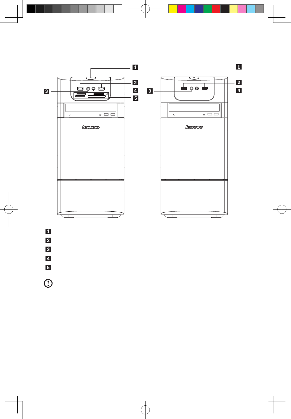
1.1 Front view of the chassis
Power button
USB connector
Headphone connector
Microphone connector
Memory Card Reader (some models are equipped with this connector).
Note: Some models are not equipped with a CD drive.
31040540_3000 H_UG_EN_V3.0.indd 2 2009.9.7 2:30:48 PM
3
User Guide
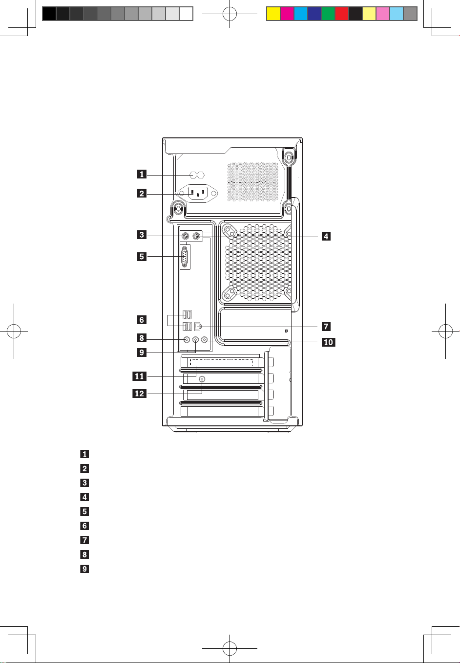
1.2 Rear view of the chassis
(If the rear view configuration in this chapter is different from your actual computer,
the rear view configuration of your actual computer should be taken as final and
binding)
Voltage selection switch (Some models are equipped with this switch)
Power connector
PS/2 keyboard connector
PS/2 mouse connector
On-board VGA connector ( Some models are equipped with this connector )
USB connectors
Ethernet connector
Microphone connector
Audio line-out connector
31040540_3000 H_UG_EN_V3.0.indd 3 2009.9.7 2:30:49 PM
4
User Guide
Audio line-in connector
PCI Express x16 graphics adapter connector (Some models are equipped
with this connector. For more information about the graphics adapter, see
the description below).
WiFi antenna connector (This connector only equipped on the model with
WiFi card. For more information about this connector, see WM600-B-LO
Wireless 802. 11b/g Wireless PCI-E Adapter Card User Manual.)
1.3 Connecting your computer
Use the following information when connecting your computer.
• Look for the small connector icons on the back of your computer. Match the
connectors to the icons.
• If your computer cables and connector panel have color-coded connectors,
match the color of the cable end with the color of the connector.
Note: Your computer might not have all of the connectors that are
described in this section.
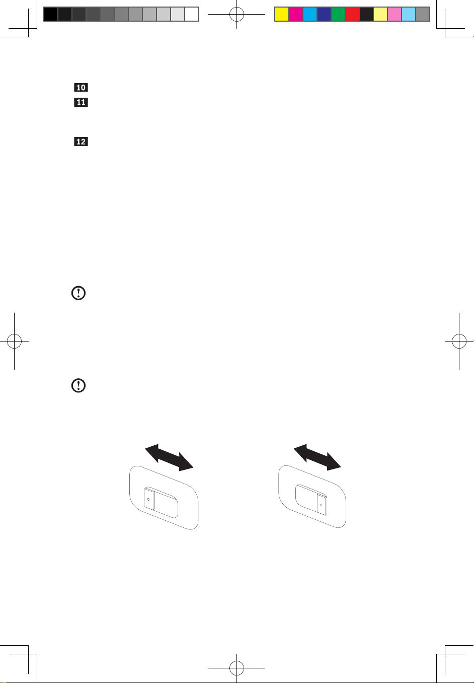
1.3.1 Check the position of the voltage-selection switch on
the rear of the computer. Use a ballpoint pen to slide the
switch if necessary.
Note: Some computers do not have the voltage switch. These computers
automatically control the voltage.
• If the voltage supply range is 100-127 V ac, set the switch to 115 V.
• If the voltage supply range is 200-240 V ac, set the switch to 230 V.
115
2
3
0
31040540_3000 H_UG_EN_V3.0.indd 4 2009.9.7 2:30:50 PM
5
User Guide
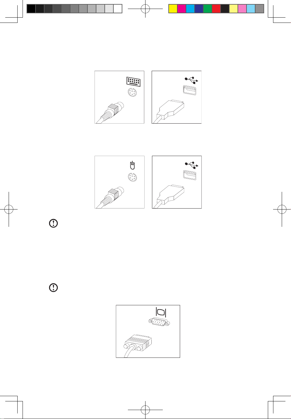
1.3.2 Connect the keyboard cable to the appropriate keyboard
connector. (PS/2 connector or USB connector )
1.3.3 Connect the mouse cable to the appropriate mouse
connector. (PS/2 connector or USB connector )
Note: If your computer is equipped with a wireless keyboard or mouse,
connect according to the relevant description.
1.3.4 Connect the monitor cable to the monitor connector on
the computer.
• If you have a Video Graphics Array (VGA) Standard monitor, connect the
cable to the connector as shown.
Note: If your model has two monitor connectors, be sure to use the
connector on the graphics adapter.
31040540_3000 H_UG_EN_V3.0.indd 5 2009.9.7 2:30:52 PM
6
User Guide
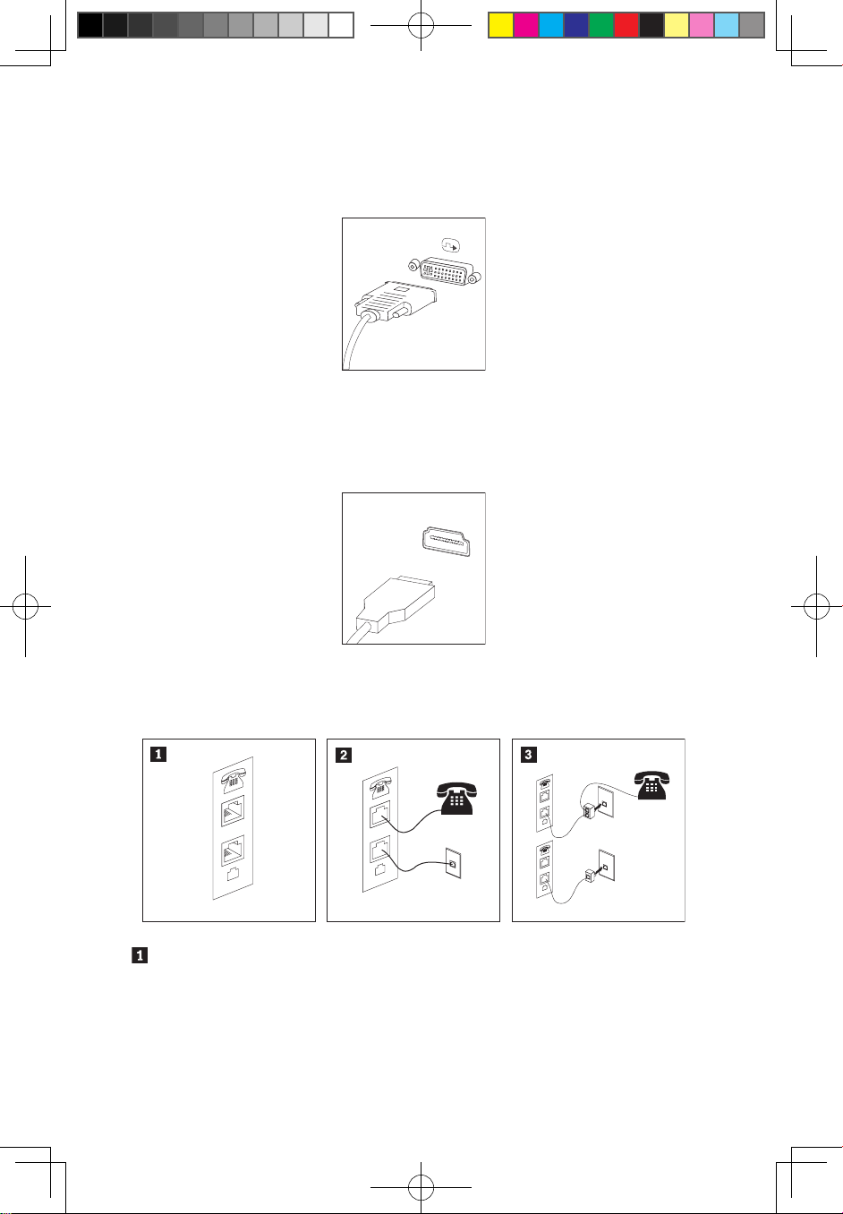
• If you have a Digital Video Interface (DVI) monitor, your computer must
have an adapter installed that supports the DVI monitor. Connect the cable
to the connector as shown.
• If you only have a DVI connector on the graphics card and the monitor
only has a VGA connector, these two connectors can be connected with a
DVI-VGA converter.
• If you have an HDMI monitor, connect the cable to the port as shown.
1.3.5 If you have a modem, connect the modem using the
following instructions:
This illustration shows two different ways of connecting the back of your
computer to the modem. Which one to use depends on the type of telephone
outlet.
31040540_3000 H_UG_EN_V3.0.indd 6 2009.9.7 2:30:53 PM
7
User Guide
In the United States and other countries or regions that use RJ-11 telephone
outlets, attach one end of the telephone cable to the telephone and the other
end to the telephone connector on the back of the computer. Attach one end
of the modem cable to the modem connector on the back of the computer
and the other end to the telephone outlet.
In countries or regions that do not use RJ-11 telephone outlets, a splitter or
converter is required to attach the cables to the telephone outlet as shown
at the top of the illustration. You can also use the splitter or converter without
the telephone as shown at the bottom of the illustration.
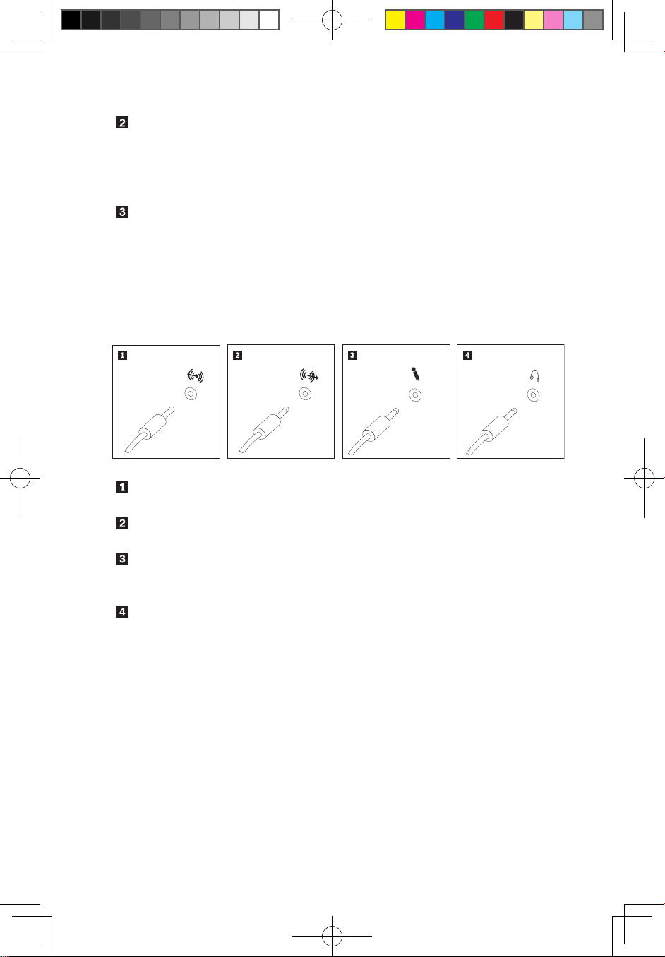
1.3.6 If you have audio devices, attach them using the
following instructions:
Audio line-in This connector receives audio signals from an external audio
device, such as a stereo system.
Audio line-out This connector sends audio signals from the computer to
external devices, such as powered stereo speakers.
Microphone Use this connector to attach a microphone to your computer
when you want to record sound or if you use speechrecognition software.
Headphone Use this connector to attach headphones to your computer
when you want to listen to music or other sounds without
disturbing anyone. This connector might be located on the
front of the computer.
31040540_3000 H_UG_EN_V3.0.indd 7 2009.9.7 2:30:53 PM
 Loading...