


HardwareMaintenanceManual
ThinkPadX200,X200s,X200si,X201,X201i,andX201s

Note
Beforeusingthisinformationandtheproductitsupports,besuretoreadthegeneralinformationunder
AppendixA“Notices”onpage269
.
EleventhEdition(September2012)
©CopyrightLenovo2010,2012.
LIMITEDANDRESTRICTEDRIGHTSNOTICE:IfdataorsoftwareisdelivereddeliveredpursuantaGeneralServices
Administration“GSA”contract,use,reproduction,ordisclosureissubjecttorestrictionssetforthinContractNo.
GS-35F-05925.

Contents
Aboutthismanual...........iii
Chapter1.Safetyinformation......1
Generalsafety................1
Electricalsafety...............2
Safetyinspectionguide............3
Handlingdevicesthataresensitivetoelectrostatic
discharge..................3
Groundingrequirements............4
Safetynotices(multilingualtranslations)......4
Lasercompliancestatement(multilingual
translations)................22
Chapter2.Importantservice
information..............29
StrategyforreplacingFRUs.........29
Strategyforreplacingaharddiskdrive...30
Importantnoticeforreplacingasystem
board................30
Howtouseerrormessage........30
StrategyforreplacingFRUsforCTO,CMV ,and
GAV...................30
Productdenition............30
FRUidenticationforCTO,CMV,andGAV
products...............31
Chapter3.Generalcheckout.....33
Whattodorst..............33
Checkoutguide..............34
SystemsupportingtheLenovoThinkVantage
ToolboxprogramandthePC-DoctorforDOS
diagnosticsprogram..........34
SystemsupportingtheLenovodiagnostics
programs...............39
Powersystemcheckout...........41
Checkingtheacadapter.........41
Checkingoperationalcharging......42
Checkingthebatterypack........42
Checkingthebackupbattery.......42
Chapter4.Relatedservice
information..............45
RestoringthefactorycontentsbyusingProduct
Recoverydiscs..............45
RestoringthefactorycontentsbyusingRecovery
DiscSet.................45
Passwords................47
Power-onpassword...........47
Hard-diskpassword...........47
Supervisorpassword..........47
Howtoremovethepower-onpassword...47
Howtoremovethehard-diskpassword...48
Powermanagement............48
Screenblankmode...........48
Sleep(Standby)mode..........49
Hibernationmode...........49
Symptom-to-FRUindex...........50
Numericerrorcodes..........51
Errormessages............55
Beepsymptoms............56
No-beepsymptoms...........56
LCD-relatedsymptoms.........56
Intermittentproblems..........57
Undeterminedproblems.........57
Chapter5.Statusindicators.....59
Chapter6.Fnkeycombinations...63
Chapter7.FRUreplacement
notices................65
Screwnotices...............65
Retainingserialnumbers...........66
Restoringtheserialnumberofthesystem
unit.................66
RetainingtheUUID...........67
ReadingorwritingtheECAinformation...67
Chapter8.Removingandreplacinga
FRU..................69
BeforeservicingThinkPadX200,X200s,X200si,
X201,X201i,andX201s...........70
1010Batterypack.............71
1020Harddiskdrive(HDD)cover,HDD,andHDD
rubberrailsorsolidstatedrive(SSD)andstorage
converter.................71
1030DIMM................74
1040Keyboard..............77
1050Palmrestorpalmrestwithngerprint
reader..................80
1060Backupbattery............82
1070PCIExpressMiniCardforwireless
LAN/WiMAX................83
1080PCIExpressMiniCardforwirelessWAN..86
1090IntelT urboMemoryMinicardorWirelessUSB
PCIExpressHalf-MiniCard.........87
1100Keyboardbezel............88
©CopyrightLenovo2010,2012
i

1110Monauralspeakerassembly(forX200,
X200s,X201s,andX201si)..........89
1120I/Ocardassembly...........90
1130LCDassembly............92
1140Basecoverassemblyandstereospeaker
assemblyforX201andX201i.........95
1150Systemboard,DC-inconnector,fan,and
ExpressCardslotassembly..........100
2010LCDfrontbezel............111
2020InvertercardorLEDboard........113
2030Bluetoothdaughtercard(BDC-2.1)....115
2040Integratedcamera...........116
2050LCDpanel,LCDbrackets,andLCDcable..117
2060Hingesandhingebrackets........122
2070LCDrearcoverandwirelessantenna
cables..................124
Chapter9.Locations........131
Frontview................131
Rearview.................132
Bottomview...............133
Rearview(ThinkPadX200UltraBase)......133
Bottomview(ThinkPadX200UltraBase).....134
LCDFRUs................220
12.1-in.WXGATFT...........221
12.1-in.WXGA+TFT..........242
Keyboard.................246
Miscellaneousparts............247
ACadapters...............247
Powercords...............248
Recoverydiscs..............249
WindowsXPProfessional(32bit)DVDs...249
WindowsVistaHomeBasic(32-bit)DVDs..251
WindowsVistaHomePremium(32-bit)
DVDs................252
WindowsVistaBusiness(32-bit)DVDs...253
WindowsVistaBusiness(64-bit)DVDs...255
WindowsVistaUltimate(32-bit)DVDs....256
Windows7HomeBasic(32-bit)DVDs...258
Windows7HomePremium(32-bit)DVDs..259
Windows7HomePremium(64-bit)DVDs..260
Windows7Professional(32-bit)DVDs...262
Windows7Professional(64-bit)DVDs...265
Windows7Starter(32-bit)DVDs......266
Commonservicetools...........267
Chapter10.Partslist........135
Overall..................136
AppendixA.Notices.........269
Trademarks................270
iiHardwareMaintenanceManual

Aboutthismanual
ThismanualcontainsserviceandreferenceinformationforthefollowingThinkPad
ThinkPadX200MT7454,7455,7457,7458,7459,2023,and2024
ThinkPadX200sandX200siMT7462,7465,7466,7469,7470,2046,and2047
ThinkPadX201andX201iMT3249,3323,3357,3626,3680,3712,and4492
ThinkPadX201sMT5129,5143,5385,5397,5413,5442,and5446
Usethismanualalongwiththeadvanceddiagnosticteststotroubleshootproblems.
Important:ThismanualisintendedonlyfortrainedservicetechnicianswhoarefamiliarwithThinkPad
products.Usethismanualalongwiththeadvanceddiagnosticteststotroubleshootproblemseffectively.
BeforeservicingaThinkPadproduct,besuretoreadalltheinformationunderChapter1“Safetyinformation”
onpage1
andChapter2“Importantserviceinformation”onpage29.
®
products.
©CopyrightLenovo2010,2012
iii

ivHardwareMaintenanceManual

Chapter1.Safetyinformation
Thischapterpresentsfollowingsafetyinformationthatyouneedtobefamiliarwithbeforeyouservice
aThinkPadNotebook.
•“Generalsafety”onpage1
•“Electricalsafety”onpage2
•“Safetyinspectionguide”onpage3
•“Handlingdevicesthataresensitivetoelectrostaticdischarge”onpage3
•“Groundingrequirements”onpage4
•“Safetynotices(multilingualtranslations)”onpage4
•“Lasercompliancestatement(multilingualtranslations)”onpage22
Generalsafety
Followtheserulestoensuregeneralsafety:
•Observegoodhousekeepingintheareaofthemachinesduringandaftermaintenance.
•Whenliftinganyheavyobject:
1.Makesurethatyoucanstandsafelywithoutslipping.
2.Distributetheweightoftheobjectequallybetweenyourfeet.
3.Useaslowliftingforce.Nevermovesuddenlyortwistwhenyouattempttolift.
4.Liftbystandingorbypushingupwithyourlegmuscles;thisactionremovesthestrainfromthe
musclesinyourback.Donotattempttoliftanyobjectthatweighsmorethan16kg(35lb)orthat
youthinkistooheavyforyou.
•Donotperformanyactionthatcauseshazardstothecustomer,orthatmakestheequipmentunsafe.
•Beforeyoustartthemachine,makesurethatotherservicetechniciansandthecustomer'spersonnelare
notinahazardousposition.
•Placeremovedcoversandotherpartsinasafeplace,awayfromallpersonnel,whileyouareservicing
themachine.
•Keepyourtoolcaseawayfromwalkareassothatotherpeoplewillnottripoverit.
•Donotwearlooseclothingthatcanbetrappedinthemovingpartsofamachine.Makesurethatyour
sleevesarefastenedorrolledupaboveyourelbows.Ifyourhairislong,fastenit.
•Inserttheendsofyournecktieorscarfinsideclothingorfastenitwithanonconductiveclip,about8
centimeters(3inches)fromtheend.
•Donotwearjewelry,chains,metal-frameeyeglasses,ormetalfastenersforyourclothing.
Attention:Metalobjectsaregoodelectricalconductors.
•Wearsafetyglasseswhenyouarehammering,drilling,soldering,cuttingwire,attachingsprings,using
solvents,orworkinginanyotherconditionsthatmightbehazardoustoyoureyes.
•Afterservice,reinstallallsafetyshields,guards,labels,andgroundwires.Replaceanysafetydevice
thatiswornordefective.
•Reinstallallcoverscorrectlybeforereturningthemachinetothecustomer.
•Fanlouversonthemachinehelptopreventoverheatingofinternalcomponents.Donotobstructfan
louversorcoverthemwithlabelsorstickers.
©CopyrightLenovo2010,2012
1

Electricalsafety
Observethefollowingruleswhenworkingonelectricalequipment.
Important:Useonlyapprovedtoolsandtestequipment.Somehandtoolshavehandlescoveredwithasoft
materialthatdoesnotinsulateyouwhenworkingwithliveelectricalcurrents.
Manycustomershave,neartheirequipment,rubberoormatsthatcontainsmallconductivebersto
decreaseelectrostaticdischarges.Donotusethistypeofmattoprotectyourselffromelectricalshock.
•Findtheroomemergencypower-off(EPO)switch,disconnectingswitch,orelectricaloutlet.Ifanelectrical
accidentoccurs,youcanthenoperatetheswitchorunplugthepowercordquickly.
•Donotworkaloneunderhazardousconditionsornearequipmentthathashazardousvoltages.
•Disconnectallpowerbefore:
–Performingamechanicalinspection
–Workingnearpowersupplies
–Removingorinstallingmainunits
•Beforeyoustarttoworkonthemachine,unplugthepowercord.Ifyoucannotunplugit,askthecustomer
topower-offthewallboxthatsuppliespowertothemachine,andtolockthewallboxintheoffposition.
•Ifyouneedtoworkonamachinethathasexposedelectricalcircuits,observethefollowingprecautions:
–Ensurethatanotherperson,familiarwiththepower-offcontrols,isnearyou.
Attention:Anotherpersonmustbetheretoswitchoffthepower,ifnecessary.
–Useonlyonehandwhenworkingwithpowered-onelectricalequipment;keeptheotherhandinyour
pocketorbehindyourback.
Attention:Anelectricalshockcanoccuronlywhenthereisacompletecircuit.Byobservingtheabove
rule,youmaypreventacurrentfrompassingthroughyourbody.
–Whenusingtesters,setthecontrolscorrectlyandusetheapprovedprobeleadsandaccessoriesfor
thattester.
–Standonsuitablerubbermats(obtainedlocally,ifnecessary)toinsulateyoufromgroundssuchas
metaloorstripsandmachineframes.
Observethespecialsafetyprecautionswhenyouworkwithveryhighvoltages;Instructionsforthese
precautionsareinthesafetysectionsofmaintenanceinformation.Useextremecarewhenmeasuring
highvoltages.
•Regularlyinspectandmaintainyourelectricalhandtoolsforsafeoperationalcondition.
•Donotusewornorbrokentoolsandtesters.
•Neverassumethatpowerhasbeendisconnectedfromacircuit.First,checkthatithasbeenpoweredoff.
•Alwayslookcarefullyforpossiblehazardsinyourworkarea.Examplesofthesehazardsaremoistoors,
nongroundedpowerextensioncables,powersurges,andmissingsafetygrounds.
•Donottouchliveelectricalcircuitswiththereectivesurfaceofaplasticdentalmirror.Thesurfaceis
conductive;suchtouchingcancausepersonalinjuryandmachinedamage.
•Donotservicethefollowingpartswiththepoweronwhentheyareremovedfromtheirnormaloperating
placesinamachine:
–Powersupplyunits
–Pumps
–Blowersandfans
–Motorgenerators
–Similarunitstolistedabove
Thispracticeensurescorrectgroundingoftheunits.
•Ifanelectricalaccidentoccurs:
2HardwareMaintenanceManual

–Usecaution;donotbecomeavictimyourself.
–Switchoffpower.
–Sendanotherpersontogetmedicalaid.
Safetyinspectionguide
Thepurposeofthisinspectionguideistoassistyouinidentifyingpotentiallyunsafeconditions.Aseach
machinewasdesignedandbuilt,requiredsafetyitemswereinstalledtoprotectusersandservicetechnicians
frominjury.Thisguideaddressesonlythoseitems.Y oushouldusegoodjudgmenttoidentifypotential
safetyhazardsduetoattachmentofnon- ThinkPadfeaturesoroptionsnotcoveredbythisinspectionguide.
Ifanyunsafeconditionsarepresent,youmustdeterminehowserioustheapparenthazardcouldbeand
whetheryoucancontinuewithoutrstcorrectingtheproblem.
Considertheseconditionsandthesafetyhazardstheypresent:
•Electricalhazards,especiallyprimarypower(primaryvoltageontheframecancauseseriousorfatal
electricalshock)
•Explosivehazards,suchasadamagedCRTfaceorabulgingcapacitor
•Mechanicalhazards,suchaslooseormissinghardware
Todeterminewhetherthereareanypotentiallyunsafeconditions,usethefollowingchecklistatthebeginning
ofeveryservicetask.Beginthecheckswiththepoweroff,andthepowercorddisconnected.
Checklist:
1.Checkexteriorcoversfordamage(loose,broken,orsharpedges).
2.Poweroffthecomputer.Disconnectthepowercord.
3.Checkthepowercordfor:
a.Athird-wiregroundconnectoringoodcondition.Useametertomeasurethird-wireground
continuityfor0.1ohmorlessbetweentheexternalgroundpinandtheframeground.
b.Thepowercordshouldbethetypespeciedinthepartslist.
c.Insulationmustnotbefrayedorworn.
4.Checkforcrackedorbulgingbatteries.
5.Removethecover.
6.Checkforanyobviousnon- ThinkPadalterations.Usegoodjudgmentastothesafetyofany
non-ThinkPadalterations.
7.Checkinsidetheunitforanyobviousunsafeconditions,suchasmetallings,contamination,wateror
otherliquids,orsignsofreorsmokedamage.
8.Checkforworn,frayed,orpinchedcables.
9.Checkthatthepower-supplycoverfasteners(screwsorrivets)havenotbeenremovedortamperedwith.
Handlingdevicesthataresensitivetoelectrostaticdischarge
Anycomputerpartcontainingtransistorsorintegratedcircuits(ICs)shouldbeconsideredsensitiveto
electrostaticdischarge(ESD.)ESDdamagecanoccurwhenthereisadifferenceinchargebetweenobjects.
ProtectagainstESDdamagebyequalizingthechargesothatthemachine,thepart,theworkmat,andthe
personhandlingthepartareallatthesamecharge.
Notes:
1.Useproduct-specicESDprocedureswhentheyexceedtherequirementsnotedhere.
Chapter1.Safetyinformation3

2.MakesurethattheESDprotectivedevicesyouusehavebeencertied(ISO9000)asfullyeffective.
WhenhandlingESD-sensitiveparts:
•Keepthepartsinprotectivepackagesuntiltheyareinsertedintotheproduct.
•Avoidcontactwithotherpeople.
•Wearagroundedwriststrapagainstyourskintoeliminatestaticonyourbody.
•Preventthepartfromtouchingyourclothing.Mostclothingisinsulativeandretainsachargeevenwhen
youarewearingawriststrap.
•Useagroundedworkmattoprovideastatic-freeworksurface.Thematisespeciallyusefulwhen
handlingESD-sensitivedevices.
•Selectagroundingsystem,suchasthoselistedbelow,toprovideprotectionthatmeetsthespecic
servicerequirement.
Note:TheuseofagroundingsystemtoguardagainstESDdamageisdesirablebutnotnecessary.
–AttachtheESDgroundcliptoanyframeground,groundbraid,orgreen-wireground.
–Whenworkingonadouble-insulatedorbattery-operatedsystem,useanESDcommongroundor
referencepoint.Y oucanusecoaxorconnector-outsideshellsonthesesystems.
–Usetheroundgroundprongoftheacplugonac-operatedcomputers.
Groundingrequirements
Electricalgroundingofthecomputerisrequiredforoperatorsafetyandcorrectsystemfunction.Proper
groundingoftheelectricaloutletcanbeveriedbyacertiedelectrician.
Safetynotices(multilingualtranslations)
Thesafetynoticesinthissectionareprovidedinthefollowinglanguages:
•English
•Arabic
•BrazilianPortuguese
•French
•German
•Hebrew
•Japanese
•Korean
•Spanish
•T raditionalChinese
4HardwareMaintenanceManual

DANGER
DANGER
DANGER
DANGER
DANGER
Chapter1.Safetyinformation5
DANGER
DANGER
6HardwareMaintenanceManual
Chapter1.Safetyinformation7
8HardwareMaintenanceManual
PERIGO
PERIGO
PERIGO
PERIGO
PERIGO
Chapter1.Safetyinformation9
PERIGO
PERIGO
10HardwareMaintenanceManual
DANGER
DANGER
DANGER
DANGER
DANGER
Chapter1.Safetyinformation11
DANGER
DANGER
12HardwareMaintenanceManual
VORSICHT
VORSICHT
VORSICHT
VORSICHT
VORSICHT
Chapter1.Safetyinformation13
VORSICHT
VORSICHT
14HardwareMaintenanceManual
Chapter1.Safetyinformation15
16HardwareMaintenanceManual
Chapter1.Safetyinformation17
18HardwareMaintenanceManual
Chapter1.Safetyinformation19
20HardwareMaintenanceManual
Chapter1.Safetyinformation21
Lasercompliancestatement(multilingualtranslations)
Thelasercompliancestatementsinthissectionareprovidedinthefollowinglanguages:
•English
•Arabic
•BrazilianPortuguese
•French
•German
•Hebrew
•Japanese
•Korean
•Spanish
•T raditionalChinese
22HardwareMaintenanceManual
Chapter1.Safetyinformation23
24HardwareMaintenanceManual

Chapter1.Safetyinformation25

26HardwareMaintenanceManual

Chapter1.Safetyinformation27

28HardwareMaintenanceManual

Chapter2.Importantserviceinformation
Thischapterpresentsfollowingimportantserviceinformationthatappliestoallmachinetypessupportedby
thismanual:
•“StrategyforreplacingFRUs”onpage29
–“Strategyforreplacingaharddiskdrive”onpage30
–“Importantnoticeforreplacingasystemboard”onpage30
–“Howtouseerrormessage”onpage30
•“StrategyforreplacingFRUsforCTO,CMV ,andGAV”onpage30
–“Productdenition”onpage30
–“FRUidenticationforCTO,CMV ,andGAVproducts”onpage31
Important:BIOSanddevicedriverxesarecustomer-installable.TheBIOSanddevicedriversareposted
onthecustomersupportsitehttp://www.lenovo.com/support/phone
SystemDisassembly/ReassemblyvideosthatshowtheFRUremovalsorreplacements
fortheLenovo
http://www.lenovoservicetraining.com/ion/
®
authorizedservicetechniciansareavailableinthefollowingsupportsite:
StrategyforreplacingFRUs
Beforereplacingparts:
Makesurethatallsoftwarexes,drivers,andBIOSdownloadsareinstalledbeforereplacinganyFRUs
listedinthismanual.
Afterasystemboardisreplaced,ensurethatthelatestBIOSisloadedtothesystemboardbefore
completingtheserviceaction.
Todownloadsoftwarexes,drivers,andBIOS,doasfollows:
1.Gotohttp://support.lenovo.com
2.EntertheproductnumberofthecomputerorpressAuto-detectbuttononthescreen.
3.SelectDownloadsanddrivers.
4.Followthedirectionsonthescreenandinstallthenecessarysoftware.
UsethefollowingstrategytopreventunnecessaryexpenseforreplacingandservicingFRUs:
•IfyouareinstructedtoreplaceaFRUbutthereplacementdoesnotcorrecttheproblem,reinstall
theoriginalFRUbeforeyoucontinue.
•Somecomputershavebothaprocessorboardandasystemboard.Ifyouareinstructedtoreplaceeither
theprocessorboardorthesystemboard,andreplacingoneofthemdoesnotcorrecttheproblem,
reinstallthatboard,andthenreplacetheotherone.
•IfanadapteroradeviceconsistsofmorethanoneFRU,anyoftheFRUsmaybethecauseoftheerror.
Beforereplacingtheadapterordevice,removetheFRUs,onebyone,toseeifthesymptomschange.
ReplaceonlytheFRUthatchangedthesymptoms.
Attention:Thesetupcongurationonthecomputeryouareservicingmayhavebeencustomized.Running
AutomaticCongurationmayalterthesettings.Notethecurrentcongurationsettings(usingtheView
Congurationoption);then,whenservicehasbeencompleted,verifythatthosesettingsremainineffect.
©CopyrightLenovo2010,2012
29

Strategyforreplacingaharddiskdrive
Alwaystrytorunalow-levelformatbeforereplacingaharddiskdrive.Thiswillcauseallcustomerdataon
theharddisktobelost.Besurethatthecustomerhasacurrentbackupofthedatabeforedoingthistask.
Attention:Thedrivestartupsequenceinthecomputeryouareservicingmayhavebeenchanged.Be
extremelycarefulduringwriteoperationssuchascopying,saving,orformatting.Ifyouselectanincorrect
drive,dataorprogramscanbeoverwritten.
Importantnoticeforreplacingasystemboard
Somecomponentsmountedonasystemboardareverysensitive.Improperhandlingofasystemboardcan
causedamagetothosecomponents,andmaycauseasystemmalfunction.
Attention:Whenhandlingasystemboard:
•Donotdropasystemboardorapplyanyexcessiveforcetoit.
•Avoidroughhandlingofanykind.
•AvoidbendingasystemboardandhardpushingtopreventcrackingateachBGA(BallGridArray)chipset.
Howtouseerrormessage
Usetheerrorcodesdisplayedonthescreentodiagnosefailures.Ifmorethanoneerrorcodeisdisplayed,
beginthediagnosiswiththersterrorcode.Whatevercausesthersterrorcodemayalsocausefalseerror
codes.Ifnoerrorcodeisdisplayed,seewhethertheerrorsymptomislistedintheSymptom-to-FRU
Indexforthecomputeryouareservicing.
StrategyforreplacingFRUsforCTO,CMV,andGAV
Productdenition
DynamicCongureToOrder(CTO)
ThisprovidestheabilityforacustomertocongureaLenovosolutionfromaneSite,andhavethis
congurationsenttofulllment,whereitisbuiltandshippeddirectlytothecustomer.Themachinelabel,
ProductEntitlementWarehouse(PEW),eSupport,andtheHMMwillloadtheseproductsasthe4-digitMT
and3-digitmodel,wheremodel=“CTO”(Example:1829-CTO).
CustomModelVariant(CMV)
ThisisauniquecongurationthathasbeennegotiatedbetweenLenovoandthecustomer.Aunique4-digit
MTand3-digitmodelisprovidedtothecustomertoplaceorders(Example:1829-W15).ACMVisaspecial
bidoffering.Therefore,itisNOTgenerallyannounced.
•TheMTMportionofthemachinelabelisthe4-digitMTand3-digitmodel,wheremodel=“CTO”
(Example:1829-CTO).ThePRODUCTIDportionofthemachinelabelisthe4-digitMTand3-digitCMV
model(Example:1829-W15).
•ThePEWrecordisthe4-digitMTand3-digitmodel,wheremodel=“CTO”(Example:1829-CTO).
•eSupportwillshowboththeCTOandCMVmachinetypemodels(Example:1829-CTOand1829-W15
willbefoundontheeSupportsite.)
•TheHMMwillhavethe4-digitMTand3-digitCTOmodelonly(Example:1829-CTO).Again,CMVsare
custommodelsandarenotfoundintheHMM.
30HardwareMaintenanceManual

GeneralAnnounceVariant(GAV)
Thisisastandardmodel(xedconguration).GAVsareannouncedandofferedtoallcustomers.TheMTM
portionofthemachinelabelisa4-digitMTand3-digitmodel,wheremodel=a“xedpartnumber”,not
“CTO”(Example:1829-F1U).Also,PEW,eSupport,andtheHMMwilllisttheseproductsunderthesame
xedmodelnumber.
FRUidenticationforCTO,CMV ,andGAVproducts
TherearethreeinformationresourcestoidentifywhichFRUsareusedtosupportCTO,CMV ,andGAV
products.ThesesourcesarePEW,eSupport,andtheHMM.
UsingPEW
•PEWistheprimarysourceforidentifyingFRUpartnumbersandFRUdescriptionsforthekeycommodities
forCTO,CMVandGAVproductsataMT-serialnumberlevel.Anexampleofkeycommoditiesarehard
diskdrives,systemboards,microprocessors,LiquidCrystalDisplays(LCDs),andmemory.
•Remember,allCTOandCMVproductsareloadedinPEWunderthe4-digitMTand3-digitmodel,where
model=“CTO”(Example:1829-CTO).GAVsareloadedinPEWunderthe4-digitMTand3-digitmodel,
wheremodel=a“xedpartnumber”,not“CTO”(Example:1829-F1U).
•PEWcanbeaccessedatthefollowingWebsite:
http://www.lenovo.com/support/site.wss/document.do?lndocid=LOOK-WARNTY
SelectWarrantylookup.InputtheMTandtheSerialnumberandthelistofkeycommoditieswillbe
returnedinthePEWrecordunderCOMPONENTINFORMA TION.
UsingeSupport
Forkeycommodities(examples-harddiskdrive,systemboard,microprocessor,LCD,andmemory)
eSupportcanbeusedtoviewthewarrantystatusofkeycommoditiesbuiltinaparticularmachineserial(this
isthesamerecordfoundinPEW).eSupportcanbeaccessedathttp://www.lenovo.com/support.
Toviewthewarrantystatusofthekeycommoditiesonyourcomputer,dothefollowing:
1.Gotohttp://www.lenovo.com/support.
2.ClickWarranty&Services.
3.ClickCheckWarrantyStatus.
4.OntheWarrantyStatusLookuppage,clickPartsLookup.
5.Typeyourmachinetypeandserialnumber,andthenclickSubmit.
FortheremainingFRUs(thecompletelistofFRUsattheMTmodellevel)
eSupportalsocanbeusedtoviewthecompletelistofFRUsforamachinetypeandmodel.
ToviewthecompletelistofFRUs,dothefollowing:
1.Gotohttp://www.lenovo.com/support.
2.ClickParts&Accessories.
3.ProvideyourproductinformationorclickLaunchtoautomaticallyidentifyyourproduct.
4.ClickProduct&PartsDetail.
5.OnthePRODUCTANDP ARTSDET AILpage,clickPartsDetailtoviewthecompletelistofFRUs.
UsingtheHardwareMaintenanceManual
Forkeycommodities(examples-harddiskdrive,systemboard,microprocessor,LCD,andmemory)
Chapter2.Importantserviceinformation31

UsetheHardwareMaintenanceManualasabackuptoPEWandeSupporttoviewthecompletelistof
FRUsattheMTmodellevel.
32HardwareMaintenanceManual

Chapter3.Generalcheckout
Thischapterpresentsfollowinginformation:
•“Whattodorst”onpage33
•“Checkoutguide”onpage34
–“SystemsupportingtheLenovoThinkVantageT oolboxprogramandthePC-DoctorforDOS
diagnosticsprogram”onpage34
–“SystemsupportingtheLenovodiagnosticsprograms”onpage39
•“Powersystemcheckout”onpage41
ThedescriptionsinthischapterapplytoanyThinkPadmodelthatsupportsthePC-Doctor
diagnosticsprogram.Somedescriptionsmightnotapplytoyourparticularcomputer.
Beforeyougotothecheckoutguide,besuretoreadthefollowingimportantnotes.
Importantnotes:
•Onlycertiedtrainedpersonnelshouldservicethecomputer.
•BeforereplacinganyFRU,readtheentirepageonremovingandreplacingFRUs.
•WhenyoureplaceFRUs,itisrecommendedtousenewnylon-coatedscrews.
•Beextremelycarefulduringsuchwriteoperationsascopying,saving,orformatting.Drivesinthe
computerthatyouareservicingsequencemighthavebeenaltered.Ifyouselectanincorrectdrive,
dataorprogramsmightbeoverwritten.
•ReplaceaFRUonlywithanotherFRUofthecorrectmodel.WhenyoureplaceaFRU,makesurethat
themodelofthemachineandtheFRUpartnumberarecorrectbyreferringtotheFRUpartslist.
•AFRUshouldnotbereplacedbecauseofasingle,unreproduciblefailure.Singlefailurescanoccur
foravarietyofreasonsthathavenothingtodowithahardwaredefect,suchascosmicradiation,
electrostaticdischarge,orsoftwareerrors.ConsiderreplacingaFRUonlywhenaproblemrecurs.Ifyou
suspectthataFRUisdefective,cleartheerrorlogandrunthetestagain.Iftheerrordoesnotrecur,do
notreplacetheFRU.
•BecarefulnottoreplaceanondefectiveFRU.
®
forDOS
Whattodorst
WhenyoudoreturnaFRU,youmustincludethefollowinginformationinthepartsexchangeformor
partsreturnformthatyouattachtoit:
1.Nameandphonenumberofservicetechnician
2.Dateofservice
3.Dateonwhichthemachinefailed
4.Dateofpurchase
5.Failuresymptoms,errorcodesappearingonthedisplay,andbeepsymptoms
6.ProcedureindexandpagenumberinwhichthefailingFRUwasdetected
7.FailingFRUnameandpartnumber
8.Machinetype,modelnumber,andserialnumber
9.Customer'snameandaddress
Noteforwarranty:Duringthewarrantyperiod,thecustomermayberesponsibleforrepaircostsifthe
computerdamagewascausedbymisuse,accident,modication,unsuitablephysicaloroperating
environment,orimpropermaintenancebythecustomer.
Followingisalistofsomecommonitemsthatarenotcoveredunderwarrantyandsomesymptomsthat
mightindicatethatthesystemwassubjectedtostressbeyondnormaluse.
©CopyrightLenovo2010,2012
33

Beforecheckingproblemswiththecomputer,determinewhetherthedamageiscoveredunderthewarranty
byreferringtothefollowinglist:
Thefollowingarenotcoveredunderwarranty:
•LCDpanelcrackedfromtheapplicationofexcessiveforceorfrombeingdropped
•Scratched(cosmetic)parts
•Distortion,deformation,ordiscolorationofthecosmeticparts
•Plasticparts,latches,pins,orconnectorsthathavebeencrackedorbrokenbyexcessiveforce
•Damagecausedbyliquidspilledintothesystem
•DamagecausedbytheimproperinsertionofaPCCardortheinstallationofanincompatiblecard
•Improperdiscinsertionoruseofanopticaldrive
•Diskettedrivedamagecausedbypressureonthediskettedrivecover,foreignmaterialinthedrive,
ortheinsertionofadiskettewithmultiplelabels
•Damagedorbentdisketteejectbutton
•Fusesblownbyattachmentofanonsupporteddevice
•Forgottencomputerpassword(makingthecomputerunusable)
•Stickykeyscausedbyspillingaliquidontothekeyboard
•Useofanincorrectacadapteronlaptopproducts
Thefollowingsymptomsmightindicatedamagecausedbynonwarrantedactivities:
•Missingpartsmightbeasymptomofunauthorizedserviceormodication.
•Ifthespindleofaharddiskdrivebecomesnoisy,itmayhavebeensubjectedtoexcessiveforce,
ordropped.
Checkoutguide
UsethefollowingproceduresasaguideinidentifyingandcorrectingproblemswiththeThinkPadNotebook.
Note:ThediagnostictestsareintendedtotestonlyThinkPadproducts.Theuseofnon- ThinkPadproducts,
prototypecards,ormodiedoptionscanleadtofalseindicationsoferrorsandinvalidsystemresponses.
1.Identifythefailingsymptomsinasmuchdetailaspossible.
2.Verifythesymptoms.Trytore-createthefailurebyrunningthediagnostictestorbyrepeatingthe
operation.
SystemsupportingtheLenovoThinkVantageT oolboxprogramandthe PC-DoctorforDOSdiagnosticsprogram
ThesectionprovidesinformationaboutThinkPadcomputersthatsupporttheLenovoThinkVantage
ToolboxprogramandthePC-Doctor
toyourparticularcomputer.
DiagnosticsusingPC-DoctorforDOS
TheThinkPadNotebookhasatestprogramcalledPC-DoctorforDOS(hereaftercalledPC-Doctor.)Y oucan
detecterrorsbyrunningthediagnosticstestincludedinPC-Doctor.
Note:PC-DoctorforDOSisavailableatthefollowingWebsite:http://support.lenovo.com.Tocreate
thePC-DoctordiagnosticCD,followtheinstructionsontheWebsite.
Forsomepossiblecongurationsofthecomputer,PC-Doctormightnotruncorrectly.T oavoidthisproblem,
youneedtoinitializethecomputersetupbyuseoftheBIOSSetupUtilitybeforeyourunPC-Doctor.
®
forDOSdiagnosticsprogram.Somedescriptionsmightnotapply
®
ToenterBIOSSetupUtility,doasfollows:
1.Turnonthecomputer.
2.WhentheThinkPadlogocomesup,immediatelypressF1toentertheBIOSSetupUtility.
34HardwareMaintenanceManual

Note:Ifasupervisorpasswordhasbeensetbythecustomer,BIOSSetupUtilitymenuappearsafterthe
Diagnostics
Run Normal Test
Run Quick Test
CPU/Coprocessor
Systemboard
Video Adapter
Fixed Disks
Diskette Drives
Other Devices
Communication
Advanced Memory Tests
Interactive Tests Hardware Info Utility Quit F1=Help
PC-DOCTOR 2.0 Copyright 2008 PC-Doctor, Inc. All Rights Reserved.
Use the cursor keys and ESC to move in menus.Press ENTER to select.
Wireless LAN
passwordisentered.Y oucanstartBIOSSetupUtilitybypressingEnterinsteadofenteringthesupervisor
password;however,youcannotchangetheparametersthatareprotectedbythesupervisorpassword.
OntheBIOSSetupUtilityscreen,pressF9,Enter,F10,andthenEnter.
Note:Whenyouinitializethecomputerconguration,somedevicesaredisabled,suchastheserialport.If
youtestoneofthesedevices,youwillneedtoenableitbyusingCongurationutilityforDOS.Theutilityis
availableonthefollowingWebsite:http://support.lenovo.com
PC-Doctorcannotbeusedtotestadevicethatisinthedockingstation,evenifthecomputersupportsthe
dockingstation.TotestaUSBdevice,connectittotheUSBconnectorofthecomputer.
Testingthecomputer
Note:ThePC-DoctordiagnosticCDdoesnotsupportanyopticaldrivesconnectedthroughUSBdevicesor
anyothers.ItsupportsonlytheinternalopticaldriveoftheThinkPadNotebook.
Torunthetest,doasfollows:
1.Turnoffthecomputer.
2.Makesurethattheinternalopticaldrivethatissupportedasastartupdeviceisattachedtothecomputer.
3.Turnonthecomputer.Ifthecomputercannotbepoweredon,goto“Powersystemcheckout”on
page41,andcheckthepowersources.
Ifanerrorcodeappears,goto“Symptom-to-FRUindex”onpage50.
4.WhentheThinkPadlogocomesup,immediatelypressF12toentertheBootMenu.
5.InsertthePC-DoctorCDintotheinternalopticaldrive.
6.PresscursorkeystoselectATAPICDx(x:0,1,...)andthenpressEnter.
7.Followtheinstructionsonthescreen.
8.ThemainpanelofPC-Doctorappears.
9.SelectDiagnosticswiththearrowkeys,andpressEnter.
Note:Youcanselectanitemnotonlywiththearrowkeys,butalsowiththeT rackPoint
®
InsteadofpressingEnter,clicktheleftbutton.
Apull-downmenuappears.(Itsexactformdependsonthemodel.)
Note:PC-Doctormenudoesnotmeantheformalsupportdevicelist.Someunsupporteddevicenames
mayappearinthePC-Doctormenu.
Theoptionsonthetestmenuareasfollows:
pointer.
Chapter3.Generalcheckout35

DiagnosticsInteractiveTests
•RunNormalT est
•RunQuickT est
•CPU/Coprocessor
•Systemboard
•VideoAdapter
•FixedDisks
•DisketteDrives
•OtherDevices
•ThinkPadDevices
•Communication
•WirelessLAN
•AdvancedMemoryT ests
Notes:
•IntheKeyboardtestinInteractiveT ests,theFnkeyshouldbehelddownforatleast2seconds;otherwise,it
cannotbesensed.
•VideoAdaptertestsupportsonlytheLCDdisplayontheThinkPadNotebook.Ifyouhaveanexternalmonitor
attachedtoyourcomputer ,detachitbeforerunningPC-DoctorforDOS.
•T otestDigitalSignatureChip,thesecuritychipmustbesettoActive.
•T otestSerialPortsorParallelPorts,theThinkPadNotebookmustbeattachedtothedockingstation.
•Keyboard
•Video
•InternalSpeaker
•Mouse
•Diskette
•SystemLoad
•OpticalDriveT est
•IntelWLANRadioT est
10.Runtheapplicablefunctiontest.
11.Followtheinstructionsonthescreen.Ifthereisaproblem,PC-Doctorshowsmessagesdescribingit.
12.Toexitthetest,selectQuit—ExitDiag.Tocancelthetest,pressEsc.
Note:AfterrunningPC-Doctor,checkthetimeanddateonthesystemandresetthemiftheyareincorrect.
DetectingsysteminformationwithPC-Doctor
PC-Doctorcandetectthefollowingsysteminformation:
HardwareInfo
•SystemConguration
•MemoryContents
•PhysicalDiskDrives
•LogicalDiskDrives
•VGAInformation
•IDEDriveInfo
•PCIInformation
•PNPISAInfo
•SMBIOSInfo
•VESALCDInfo
•HardwareEventsLog
Utility•RunExternalTests
•SurfaceScanHardDisk
•BenchmarkSystem
•DOSShell
•T echSupportForm
•BatteryRundown
•ViewTestLog
•PrintLog
•SaveLog
•FullEraseHardDrive
•QuickEraseHardDrive
36HardwareMaintenanceManual

LenovoThinkVantageT oolbox(LenovoSystemT oolbox)
LenovoThinkVantage
®
Toolbox(LenovoSystemToolboxinWindowsVista
diagnosticprogramthatworksthroughtheWindowsoperatingsystem.Itenablesyoutoviewsymptomsof
computerproblemsandsolutionsforthem,andincludesautomaticnoticationwhenactionisrequired,
computingassistance,advanceddiagnostics,anddiagnostichistory.
Note:ThelatestLenovoThinkVantageToolbox(LenovoSystemT oolbox)isavailableatthefollowingWeb
site:http://support.lenovo.comT oinstallthelatestLenovoThinkVantageToolbox(LenovoSystemT oolbox)
onthecomputer,followtheinstructionsontheWebsite.
Torunthisprogram,doasfollows:
Windows7:
WhiletheWindowsoperatingsystemisrunning,presstheThinkVantagebutton.
Youcanalsorunthisprogramaseitherofthefollowing:
•ClickStart➙AllPrograms➙LenovoThinkVantageT ools➙SystemHealthandDiagnostics.
•ClickStart➙ControlPanel➙SystemandSecurity➙Lenovo'sSystemHealthandDiagnostics.
WindowsVistaandWindowsXP:
ClickStart➙AllPrograms➙LenovoServices.
Followtheinstructionsonthescreen.LenovoThinkVantageT oolbox(LenovoSystemT oolbox)alsohas
problemdeterminationaidsthatdeterminesoftwareandusageproblems.
®
andWindows
®
XP)isa
Foradditionalinformationaboutthisprogram,seetheHelpfortheprogram.
PC-DoctorforWindows
InsomemodelsofThinkPadNotebook,PC-DoctorforWindowsenablesyoutotroubleshootandresolve
problemsrelatedtothecomputer.
Selectoneofthecategorieslistedbelowtodisplaysymptomsandsolutions:
•CheckSystemHealth
•SystemandDeviceT ests
•LenovoTroubleshootingCenter
•SystemReports
•UpdatesandSupport
PC-DoctorforRescueandRecovery
InsomemodelsofThinkPadNotebook,theRescueandRecovery®workspaceenablesyoutorunthe
PC-Doctorprogramtotestthehardwarefeaturesofthecomputer.
Torunthetest,click“RunDiagnostics”ontheRescueandRecoverymainscreen.
FRUtests
ThefollowingtableshowsthetestforeachFRU.
Chapter3.Generalcheckout37

Table1.FRUtests
FRUApplicabletest
Systemboard1.Diagnostics➙CPU/Coprocessor.
2.Diagnostics➙Systemboard.
3.IftheThinkPadX200Ultrabase™isattachedtotheThinkPadcomputer,detachit.
Placethecomputeronahorizontalsurface,andrunDiagnostics➙ThinkPad➙
Devices➙HDDActiveProtectionT est.
Note:Donotapplyanyphysicalshocktothecomputerwhilethetestisrunning.
Power
LCDunit
Audio
SpeakerInteractiveT ests➙InternalSpeaker
PCCardslotDiagnostics➙Systemboard➙PCMCIA
ExpressCardslot1.InsertaPCI-Express/USBWrapcardintotheExpressCardslot.
Keyboard
Harddiskdrive
Diskettedrive1.Diagnostics➙DisketteDrives
Opticaldrive1.Diagnostics➙OtherDevices➙OpticalDrive
Memory
TrackPointorpointing
device
Diagnostics➙ThinkPadDevices➙ACAdapter,Battery1(Battery2)
1.Diagnostics➙VideoAdapter
2.InteractiveT ests➙Video
EntertheBIOSSetupUtilityandchangeSerialA T A(SA T A)settingtoCompatibility,
andrunDiagnostics➙OtherDevice➙ConexantAudio.
Note:OnceModem/Audiotestisdone,thenosoundisheardthistest.Inthiscase,
turnoffandturnonthecomputer.Then,runthistestagain.
2.Turnonthecomputer.
3.RunDiagnostics➙ThinkPadDevices➙ExpressCardslot.
1.Diagnostics➙Systemboard➙Keyboard
2.InteractiveT ests➙Keyboard
EntertheBIOSSetupUtilityandchangeSerialA T A(SA T A)settingtoCompatibility,
andrunDiagnostics➙FixedDisks.
Youcanalsodiagnosetheharddiskdrivewithoutstartinguptheoperatingsystem.T o
diagnosetheharddiskdrivefromtheBIOSSetupUtility,doasfollows:
1.Removeanydiskettefromthediskettedrive,andthenturnoffthecomputer.
2.Turnonthecomputer.
3.Whilethemessage,“T ointerruptnormalstartup,presstheblueThinkVangate
button,”isdisplayedatthelowerleftofthescreen,pressF1toentertheBIOS
SetupUtility.
4.Usingcursorkeys,selectHDDdiagnosticprogram.Pressenter.
5.Usingcursorkeys,selectMainharddiskdriveorUltrabayharddiskdrive.
6.PressEntertostartthediagnosticprogram.
2.InteractiveT ests➙Diskette
2.InteractiveT ests➙OpticalDriveT est
1.IftwoDIMMsareinstalled,removeoneofthemandrunDiagnostics➙PM
Memory.
2.Iftheproblemdoesnotrecur,returntheDIMMtoitsplace,removetheotherone,
andrunthetestagain.
IftheTrackPointdoesnotwork,checkthecongurationasspeciedintheBIOSSetup
Utility.IftheT rackPointisdisabled,selectAutomatictoenableit.
38HardwareMaintenanceManual
AfteryouusetheT rackPoint,thepointermaydriftonthescreenforashorttime.This
driftcanoccurwhenaslight,steadypressureisappliedtotheT rackPointpointer.
Thissymptomisnotahardwareproblem.Ifthepointerstopsafterashorttime,no
serviceactionisnecessary.
IfenablingtheT rackPointdoesnotcorrecttheproblem,continuewiththefollowing:
•InteractiveT ests➙Mouse

SystemsupportingtheLenovodiagnosticsprograms
ThesectionprovidesinformationaboutThinkPadcomputersthatsupporttheLenovodiagnosticsprograms.
Somedescriptionsmightnotapplytoyourparticularcomputer.
TheLenovodiagnosticsprogramsincludethefollowing:
•LenovoSolutionCenter
•Quicktestprograms
•UEFIdiagnosticprogram
•Bootablediagnosticprograms
LenovoSolutionCenter
TheLenovoSolutionCenterprogramenablesyoutotroubleshootandresolvecomputerproblems.It
combinesdiagnostictests,systeminformationcollection,securitystatus,andsupportinformation,along
withhintsandtipsformaximumsystemperformance.
Note:TheLenovoSolutionCenterprogramisavailableonlyonmodelspreinstalledwiththeWindows7
operatingsystem.Italsocanbedownloadedfromhttp://www.lenovo.com/diags.
ToruntheLenovoSolutionCenterprogram,clickStart➙ControlPanel➙SystemandSecurity➙Lenovo
-SystemHealthandDiagnostics,andthenfollowtheinstructionsonthescreen.
Foradditionalinformationaboutthisprogram,seethehelpinformationsystem.
Quicktestprograms
LenovoHardDriveQuickT estandLenovoMemoryQuickT estaretwoquicktestprogramsthatenableyou
totroubleshootandresolvecomputerinternalstorageandmemoryproblems.
Notes:
•IfthecomputeryouareservicingisnotinstalledwiththeLenovoSolutionCenterprogram,youcan
downloadthequicktestprogramsfromtheLenovoSupportWebsite.
•ThetwoprogramsareapplicabletocomputersinstalledwiththeWindows7,WindowsXP ,Windows
Server2003,orWindowsServer2008operatingsystem.
Todownloadandinstallaquicktestprogram,gotohttp://www.lenovo.com/diags,andfollowtheinstructions
ontheWebsite.
Torunaquicktestusingthedownloadedprogram,dothefollowing:
1.GototheC:\SWTOOLS\ldiagfolder.
2.Double-clickthegui_lsc_lite.exele.
3.WhentheUserAccountControlwindowopens,clickY es.
4.Selectthedeviceclasstobetested.
5.Selectthedevicestobetested.
6.Selecttheteststobeperformed.
7.Followtheinstructionsonthescreentostartthetest.Whenaproblemisdetected,information
messageswillbedisplayed.Refertothemessagestotroubleshoottheproblem.
UEFIdiagnosticprogram
AUEFIdiagnosticprogramispreinstalledonthecomputer.Itenablesyoutotestmemoryandinternal
storageproblems,viewsysteminformation,andcheckandrecoverbadsectorsoninternalstoragedevices.
Chapter3.Generalcheckout39

ToruntheUEFIdiagnosticprogram,dothefollowing:
1.Turnonthecomputer.Ifthecomputercannotbeturnedon,goto“Powersystemcheckout”onpage41,
andcheckthepowersources.Ifanerrorcodeisdisplayed,goto“Symptom-to-FRUindex”onpage50
forerrorcodedescriptionsandtroubleshootinghints.
2.WhentheThinkPadlogoisdisplayed,repeatedlypressandreleasetheF12key.WhentheBootMenu
windowopens,releasetheF12key.
3.PresstheTabkeytoswitchtotheApplicationMenuwindow.
4.UsethearrowkeystoselectLenovoDiagnosticsandthenpressEnter.ThemainscreenoftheUEFI
diagnosticprogramisdisplayed.
5.Followtheinstructionsonthescreentousethediagnosticprogram.
Theoptionsonthemainscreenareasfollows:
TestsTools
•QuickMemoryT est
•QuickStorageDeviceTest
•ExitApplication
•SystemInformation
•RecoverBadSectorsT ool
Bootablediagnosticprograms
IfthecomputeryouareservicingisnotinstalledwiththeUEFIdiagnosticprogram,youcandownloada
bootablediagnosticprogramfromtheLenovoSupportWebsite.Thebootablediagnosticprogramsenable
youtotestcomputermemoryandinternalstoragedevices,viewsysteminformation,andcheckandrecover
theinternalstoragedevices.T ousethebootablediagnosticprograms,youcancreateabootablediagnostic
mediumonaUSBdeviceorCD.
Tocreateabootablediagnosticmedium,dothefollowing:
1.Gotohttp://www.lenovo.com/diags.
2.ClickLenovoBootableDiagnostics.
3.FollowtheinstructionsontheWebsitetocreateabootablediagnosticmediumonaUSBdeviceorCD.
Tousethediagnosticmediumyouhavecreated,dooneofthefollowing:
•IfyouhavecreatedthebootablediagnosticmediumonaUSBdevice,dothefollowing:
1.AttachtheUSBdevicetothecomputer.
2.Turnonthecomputer.Ifthecomputercannotbeturnedon,goto“Powersystemcheckout”onpage
,andcheckthepowersources.Ifanerrorcodeisdisplayed,goto“Symptom-to-FRUindex”on
41
page50forerrorcodedescriptionsandtroubleshootinghints.
3.WhentheThinkPadlogoisdisplayed,repeatedlypressandreleasetheF12key.WhentheBoot
Menuwindowopens,releasetheF12key.
4.UsethearrowkeystoselectUSBHDDandthenpressEnter.Thediagnosticprogramwillbe
launchedautomatically.
5.Followtheinstructionsonthescreentousethediagnosticprogram.
•IfyouhavecreatedthebootablediagnosticmediumonaCD,dothefollowing:
1.Turnonthecomputer.Ifthecomputercannotbeturnedon,goto“Powersystemcheckout”onpage
41,andcheckthepowersources.Ifanerrorcodeisdisplayed,goto“Symptom-to-FRUindex”on
page50
forerrorcodedescriptionsandtroubleshootinghints.
2.InserttheCDintotheopticaldrive.
3.Restartthecomputer.
40HardwareMaintenanceManual

4.WhentheThinkPadlogoisdisplayed,repeatedlypressandreleasetheF12key.WhentheBoot
1
2
3
(20V)
Menuwindowopens,releasetheF12key.
5.UsethearrowkeystoselectATAPICDx(x:0,1,...)andthenpressEnter.Thediagnosticprogram
willbelaunchedautomatically.
6.Followtheinstructionsonthescreentousethediagnosticprogram.
Powersystemcheckout
Toverifyasymptom,dothefollowing:
1.Turnoffthecomputer.
2.Removethebatterypack.
3.Connecttheacadapter.
4.Checkthatpowerissuppliedwhenyouturnonthecomputer.
5.Turnoffthecomputer.
6.Disconnecttheacadapterandinstallthechargedbatterypack.
7.Checkthatthebatterypacksuppliespowerwhenyouturnonthecomputer.
Ifyoususpectapowerproblem,seetheappropriateoneofthefollowingpowersupplycheckouts:
•“Checkingtheacadapter”onpage41
•“Checkingoperationalcharging”onpage42
•“Checkingthebatterypack”onpage42
•“Checkingthebackupbattery”onpage42
Checkingtheacadapter
Youareherebecausethecomputerfailsonlywhentheacadapterisused.
•IfthepowerproblemoccursonlywhentheThinkPadX200UltraBaseisused,replacetheUltraBase.
•Ifthepower-onindicatordoesnotturnon,checkthepowercordoftheacadapterforcorrectcontinuity
andinstallation.
•Ifthecomputerdoesnotchargeduringoperation,goto“Checkingoperationalcharging”onpage42
Tochecktheacadapter,dothefollowing:
1.Unplugtheacadaptercablefromthecomputer.
2.Measuretheoutputvoltageattheplugoftheacadaptercable.Seethefollowinggure:
Pin
1+20
20
3
Voltage(Vdc)
Ground
Note:Outputvoltageacrosspin2oftheacpoweradaptermightdifferfromtheoneyouareservicing.
3.Ifthevoltageisnotcorrect,replacetheacadapter.
4.Ifthevoltageisacceptable,dothefollowing:
•Replacethesystemboard.
•Iftheproblempersists,goto“FRUtests”onpage37.
.
Note:Noisefromtheacadapterdoesnotalwaysindicateadefect.
Chapter3.Generalcheckout41

Checkingoperationalcharging
1(+)
2(+)
3
4
5
6(-)
7(-)
Tocheckwhetherthebatterychargesproperlyduringoperation,useadischargedbatterypackorabattery
packthathaslessthan50%ofthetotalpowerremainingwheninstalledinthecomputer.
Performoperationalcharging.Ifthebatterystatusindicatororicondoesnotturnon,removethebattery
packandletitreturntoroomtemperature.Reinstallthebatterypack.Ifthechargeindicatororiconstilldoes
notturnon,replacethebatterypack.
Ifthechargeindicatorstilldoesnotturnon,replacethesystemboard.Thenreinstallthebatterypack.Ifitis
stillnotcharged,gotothenextsection.
Checkingthebatterypack
BatterychargingdoesnotstartuntilthePowerManagerBatteryGaugeshowsthatlessthan96%ofthe
totalpowerremains;underthisconditionthebatterypackcanchargeto100%ofitscapacity.Thisprotects
thebatterypackfrombeingoverchargedorfromhavingashortenedlife.
Tocheckyourbattery,moveyourcursortothePowerManagerBatteryGaugeiconintheicontrayofthe
Windowstaskbarandwaitforamoment(butdonotclick),andthepercentageofbatterypowerremaining
isdisplayed.T ogetdetailedinformationaboutthebattery,double-clickthePowerManagerBattery
Gaugeicon.
Note:Ifthebatterypackbecomeshot,itmaynotbeabletocharge.Removeitfromthecomputerandleave
itatroomtemperatureforawhile.Afteritcoolsdown,reinstallandrechargeit.
Tocheckthebatterypack,dothefollowing:
1.Poweroffthecomputer.
2.Removethebatterypackandmeasurethevoltagebetweenbatteryterminals1(+)and7(-).Seethe
followinggure:
Terminal
1+0to+12.6
7
Voltage(Vdc)
Ground(-)
3.Ifthevoltageislessthan+11.0Vdc,thebatterypackhasbeendischarged.
Note:Rechargingwilltakeatleast3hours,eveniftheindicatordoesnotturnon.
Ifthevoltageisstilllessthan+11.0Vdcafterrecharging,replacethebattery.
4.Ifthevoltageismorethan+11.0Vdc,measuretheresistancebetweenbatteryterminals5and7.
Theresistancemustbe4to30KΩ.Iftheresistanceisnotcorrect,replacethebatterypack.Ifthe
resistanceiscorrect,replacethesystemboard.
Checkingthebackupbattery
Dothefollowing:
1.Poweroffthecomputer,andunplugtheacadapterfromit.
2.Turnthecomputerupsidedown.
3.Removethebatterypack(see“1010Batterypack”onpage71).
4.Removethebackupbattery(see“1060Backupbattery”onpage82).
42HardwareMaintenanceManual

5.Measurethevoltageofthebackupbattery.Seethefollowinggure.
Wire
Red+2.5to+3.2
Black
Voltage(Vdc)
Ground
•Ifthevoltageiscorrect,replacethesystemboard.
•Ifthevoltageisnotcorrect,replacethebackupbattery.
•Ifthebackupbatterydischargesquicklyafterreplacement,replacethesystemboard.
Chapter3.Generalcheckout43

44HardwareMaintenanceManual

Chapter4.Relatedserviceinformation
Thischapterpresentsfollowinginformation:
•“RestoringthefactorycontentsbyusingProductRecoverydiscs”onpage45
•“RestoringthefactorycontentsbyusingRecoveryDiscSet”onpage45
•“Passwords”onpage47
•“Powermanagement”onpage48
•“Symptom-to-FRUindex”onpage50
ServiceWebsite:
Whenthelatestmaintenancedisketteandthesystemprogramservicediskettebecomeavailable,theywill
bepostedonhttp://support.lenovo.com.
RestoringthefactorycontentsbyusingProductRecoverydiscs
Whentheharddiskdrive(HDD)orsolidstatedrive(SSD)isreplacedbecauseofafailure,noProduct
Recoveryprogramisonthenewdrive.Inthiscase,youmustusetherecoverydiscsforthecomputer.Order
therecoverydiscsandthedriveatthesametimesothatyoucanrecoverthenewdrivewiththepre-installed
softwarewhentheyarrive.Forinformationonwhichdiscstoorder,see“Recoverydiscs”onpage249
ToinstallthefactorycontentsbyusingProductRecoverydiscs,dothefollowing:
Note:Recoverytakesseveralhours.Thelengthoftimedependsonthemethodyouuse.Ifyouuserecovery
discs,recoverytakesatleastvehours.
1.InsertthebootableStartRecoveryDiscintotheDVDdrive.
2.SelectyourlanguageandclickNext.
3.Readthelicense.Ifyouagreewiththeterms,selectIacceptthesetermsandconditionsandthen
clickNext.
4.InserttheOperatingSystemRecoveryDiscwhenpromptedandclickY estobegintheoperating
systemrecoveryprocess.
5.InserttheProductRecoveryDiscwhenpromptedandclickOK.
6.IfyouhaveaSupplementalRecoveryDisc,insertitwhenpromptedandclickY es.Ifyoudonot
haveaSupplementalRecoveryDisc,clickNo.
.
Note:NotallrecoverydiscsetscomewithaSupplementalRecoveryDisc.IfthereisaSupplemental
RecoveryDisc,itwillbeclearlymarkedassuch.
7.Whenallofthedatahasbeencopiedfromthelastdiscintheset,amessageisdisplayedprompting
youtorestartthecomputer.RemovethediscandthenclickYes.
Note:Theremainderoftherecoveryprocessisfullyautomatedandnoactionisrequiredbyyou.The
computerwillrestartintotheWindowsdesktopseveraltimesandyoumightexperienceperiodswhen
noactivityisapparentonthescreenforseveralminutesatatime.Thisisnormal.
8.Whentherecoveryprocessiscomplete,theWelcometoMicrosoftWindowsscreenisdisplayed.Follow
theinstructionsonthescreentocompletetheWindowssetup.
RestoringthefactorycontentsbyusingRecoveryDiscSet
Whentheharddiskdrive(HDD)orsolidstatedrive(SSD)isreplacedbecauseofafailure,noproductrecovery
programisonthenewdrive.Inthiscase,youmustusetheRecoveryDiscSetforthecomputer.Orderthe
RecoveryDiscSetandthedriveatthesametimesothatyoucanrecoverthenewdrivewiththepre-installed
softwarewhentheyarrive.Forinformationonwhichdiscstoorder,see“Recoverydiscs”onpage249
©CopyrightLenovo2010,2012
.
45

TherecoverydiscsetconsistsoftheuserinstructionsandthefollowingsetofDVDstorestorethecomputer
totheoriginalfactoryconguration.
OperatingSystemRecoveryDisc(onedisc)
ThisdiscrestorestheMicrosoft
®
Windowsoperating
system.Usethisdisctostarttherecoveryprocess.
ApplicationsandDriversRecoveryDisc(oneor
morediscs)
SupplementalRecoveryDisc
Thisdiscrestoresthepreinstalledapplicationsand
driversonthecomputer.
Thisdisccontainsadditionalcontent,suchas
updatestothesoftwarethatwaspreinstalledonthe
computer.Notallrecoverydiscsetscomewitha
SupplementalRecoveryDisc.
Notes:
•Y oumusthaveaDVDdrivetousetherecoverydiscs.IfyoudonothaveaninternalDVDdrive,you
canuseanexternalUSBDVDdrive.
•Duringtherecoveryprocess,alldataonthedrivewillbedeleted.Ifpossible,copyanyimportantdata
orpersonallesthatyouwanttokeepontoremovablemediaoranetworkdrivebeforeyoustartthe
recoveryprocess.
Torestorethecomputertotheoriginalfactorycongurationusingtherecoverydiscset,dothefollowing:
Note:Recoverytakesseveralhours.Thelengthoftimedependsonthemethodyouuse.Ifyouuserecovery
discs,recoverytakesatleastvehours.
1.MaketheCD/DVDdrivetherststartupdeviceinthestartupsequenceusingthefollowingprocedure:
a.PressandholddowntheF1key,andthenturnonthecomputer.Whenthelogoscreenisdisplayed
orifyouhearrepeatingbeeps,releasetheF1key.TheSetupUtilityprogramopens.
b.UsethearrowkeystoselectStartup➙Boot.
c.SelecttheCD/DVDdriveasthe1stBootDevice.
2.InserttheOperatingSystemRecoveryDiscintotheDVDdrive.
3.PressF10tosavetheSetupUtilitycongurationchanges.Followtheinstructionsonthescreento
begintherecoveryprocess.
4.SelectyourlanguageandclickNext.
5.Readthelicense.Ifyouagreewiththetermsandconditions,selectIacceptthesetermsand
conditionsandthenclickNext.Ifyoudonotagreewiththetermsandconditions,followthe
instructionsonthescreen.
6.ClickYesinthedisplayedwindowtobegintheoperatingsystemrecoveryprocess.
7.InserttheApplicationsandDriversRecoveryDiscwhenpromptedandthenclickOKtobeginthe
applicationsanddriversrecoveryprocess.
8.IfyouhaveaSupplementalRecoveryDisc,insertitwhenpromptedandclickY es.Ifyoudonothavea
SupplementalRecoveryDisc,clickNo.
9.Whenallofthedatahasbeencopiedfromthelastdiscinthesetandhasbeenprocessed,removethe
discandrestartthecomputer.
Note:Therestoftherecoveryprocessisfullyautomatedandnoactionisrequiredbyyou.The
computerwillrestartintotheMicrosoftWindowsdesktopseveraltimesandyoumightexperience
periodswhennoactivityisapparentonthescreenforseveralminutesatatime.Thisisnormal.
10.Whentherecoveryprocessiscomplete,theSetUpWindowsscreenisdisplayed.Followthe
instructionsonthescreentocompletetheWindowssetup.
11.AfteryouhavecompletedtheWindowssetup,youmightwanttorestoretheoriginalstartupsequence.
StarttheSetupUtilityprogramandthenpressF9torestorethedefaultsettings.PressF10tosaveand
exittheSetupUtility.
46HardwareMaintenanceManual

Note:Afterrestoringadrivetothefactorydefaultsettings,youmightneedtoreinstallsomedevicedrivers.
Passwords
AsmanyasthreepasswordsmaybeneededforanyThinkPadNotebook:thepower-onpassword(POP),
thehard-diskpassword(HDP),andthesupervisorpassword(SVP).
Ifanyofthesepasswordshasbeenset,apromptforitappearsonthescreenwheneverthecomputeris
turnedon.Thecomputerdoesnotstartuntilthepasswordisentered.
Note:IfonlyanSVPisinstalled,thepasswordpromptdoesnotappearwhentheoperatingsystemisbooted.
Power-onpassword
Apower-onpassword(POP)protectsthesystemfrombeingpoweredonbyanunauthorizedperson.The
passwordmustbeenteredbeforeanoperatingsystemcanbebooted.ForhowtoremovethePOP ,see
“Howtoremovethepower-onpassword”onpage47
.
Hard-diskpassword
Therearetwohard-diskpasswords(HDPs):
•UserHDP—fortheuser
•MasterHDP—forthesystemadministrator,whocanuseittogetaccesstotheharddiskeveniftheuser
haschangedtheuserHDP
Note:TherearetwomodesfortheHDP:UseronlyandMaster+User.TheMaster+Usermoderequires
twoHDPs;thesystemadministratorentersbothinthesameoperation.Thesystemadministratorthen
providestheuserHDPtothesystemuser.
Attention:IftheuserHDPhasbeenforgotten,checkwhetheramasterHDPhasbeenset.Ifithas,itcanbe
usedforaccesstotheharddiskdrive.IfnomasterHDPisavailable,neitherLenovonorLenovoauthorized
servicetechniciansprovideanyservicestoreseteithertheuserorthemasterHDP ,ortorecoverdatafrom
theharddiskdrive.Theharddiskdrivecanbereplacedforascheduledfee.
ForhowtoremovethePOP ,see“Howtoremovethehard-diskpassword”onpage48.
Supervisorpassword
Asupervisorpassword(SVP)protectsthesysteminformationstoredintheBIOSSetupUtility.Theusermust
entertheSVPinordertogetaccesstotheBIOSSetupUtilityandchangethesystemconguration.
Attention:IftheSVPhasbeenforgottenandcannotbemadeavailabletotheservicetechnician,thereisno
serviceproceduretoresetthepassword.Thesystemboardmustbereplacedforascheduledfee.
Howtoremovethepower-onpassword
ToremoveaPOPthatyouhaveforgotten,dothefollowing:
(A)IfnoSVPhasbeenset:
1.Turnoffthecomputeranddisconnecttheacpoweradapter.
2.Removethebatterypack.Forhowtoremovethebatterypack,see“1010Batterypack”onpage71.
3.Removethebackupbattery.Forhowtoremovethebackupbattery,see“1060Backupbattery”on
page82.
Chapter4.Relatedserviceinformation47

4.Connecttheacpoweradapter.TurnonthecomputerandwaituntilthePOSTends.AfterthePOST
ends,thepasswordpromptwillnotbedisplayed.Thepower-onpasswordhasbeenremoved.
5.Reinstallthebackupbatteryandthebatterypack.
(B)IfanSVPhasbeensetandisknownbytheservicetechnician:
1.Turnonthecomputer.
2.WhentheThinkPadlogoisdisplayed,immediatelypressF1.
3.TypethesupervisorpasswordtoentertheThinkPadSetupprogram.
4.SelectSecurity.
5.SelectPassword.
6.SelectPower-OnPassword.
7.TypethecurrentsupervisorpasswordintheEnterCurrentPasswordeld.ThenleavetheEnter
NewPasswordeldblank,andpressEntertwice.
8.IntheChangeshavebeensavedwindow,pressEnter.
9.PressF10tosavechangesandexittheThinkPadSetupprogram.
Howtoremovethehard-diskpassword
Attention:IfUseronlymodeisselectedandtheuserHDPhasbeenforgottenandcannotbemade
availabletotheservicetechnician,neitherLenovonorLenovoauthorizedservicetechniciansprovideany
servicestoresettheuserHDPsortorecoverdatafromtheharddiskdrive.Theharddiskdrivecanbe
replacedforascheduledfee.
ToremoveauserHDPthathasbeenforgotten,whentheSVPandthemasterHDPareknown,dothe
following:
1.Turnonthecomputer.
2.WhentheThinkPadlogocomesup,immediatelypressF1toenterBIOSSetupUtility.Formodels
supportingthePassphrasefunction,pressF1whileHDPiconisappearingonthescreen;thenenterthe
masterHDP .Fortheothermodels,enterthemasterHDP .
Note:T ocheckwhethertheThinkPadNotebookyouareservicingsupportsthePassphrasefunction,
entertheBIOSSetupUtilityandgotoSecurity➙Password.IfUsingPassphraseitemisdisplayed
inthemenu,thisfunctionisavailableontheThinkPadNotebook.
3.SelectSecurity,usingthecursordirectionalkeystomovedownthemenu.
4.SelectPassword.
5.SelectHard-diskxpassword,wherexistheletteroftheharddiskdrive.Apop-upwindowopens.
6.SelectMasterHDP.
7.TypethecurrentmasterHDPintheEnterCurrentPasswordeld.thenleavetheEnterNewPassword
eldblank,andpressEntertwice.
8.PressF10.
9.SelectY esintheSetupCongurationwindow.BothuserHDPandmasterHDPwillhavebeenremoved.
Powermanagement
Toreducepowerconsumption,thecomputerhasthreepowermanagementmodes:screenblank,sleep
(standbyinWindowsXP),andhibernation.
Screenblankmode
Ifthetimesetonthe“T urnoffmonitor”timerintheoperatingsystemexpires,theLCDbacklightturnsoff.
48HardwareMaintenanceManual

Toputthecomputerintoscreenblankmode,doasfollows:
1.PressFn+F3.Apanelforselectingapowerplan(inWindowsXP ,powerscheme)appears.
2.SelectPoweroffdisplay(keepcurrentpowerplan)(inWindowsXP ,keepcurrentpowerscheme).
Youcanalsoputthecomputerintoscreenblankmode,pressThinkVantagebuttonandusetheThinkVantage
ProductivityCenter.
Note:IfthecomputerisaWindows7model,itdoesnotsupportThinkVantageProductivityCenter.
Toendscreenblankmodeandresumenormaloperation,pressanykey.
Sleep(Standby)mode
Whenthecomputerenterssleep(standby)mode,thefollowingeventsoccurinadditiontowhatoccurs
inscreenblankmode:
•TheLCDispoweredoff.
•Theharddiskdriveorthesolidstatedriveispoweredoff.
•TheCPUstops.
Toentersleep(standby)mode,pressFn+F4.
Note:Y oucanchangetheactionoftheFn+F4keycombinationbychangingthesettingsinPowerManager.
Incertaincircumstances,thecomputergoesintosleep(standby)modeautomatically:
•Ifa“suspendtime”hasbeensetonthetimer,andtheuserdoesnotdoanyoperationwiththekeyboard,
theT rackPoint,theharddisk,theparallelconnector,orthediskettedrivewithinthattime.
•Ifthebatteryindicatorblinksorange,indicatingthatthebatterypowerislow.
Note:Evenifyoudonotsetthelow-batteryalarm,thechargeindicatornotiesyouwhenthebatteryislow,
andthenthecomputerentersthepower-savingmodeautomatically.
Tocausethecomputertoreturnfromsleep(standby)modeandresumeoperation,dooneofthefollowing:
•PresstheFnkey.
•OpentheLCDcover.
•T urnonthepowerswitch.
Also,ineitherofthefollowingevents,thecomputerautomaticallyreturnsfromsleep(standby)modeand
resumesoperation:
•Theringindicator(RI)issignaledbyaserialdeviceoraPCCarddevice.(doesnotsupportthering
indicator(RI)resumebyPCCarddevice.)
•Thetimesetontheresumetimerelapses.
Note:Thecomputerdoesnotacceptanyinputimmediatelyafteritenterssleep(standby)mode.Waita
fewsecondsbeforetakinganyactiontoreenteroperationmode.
Hibernationmode
Inhibernationmode,thefollowingoccurs:
•Thesystemstatus,RAM,VRAM,andsetupdataarestoredontheharddisk.
•Thesystemispoweredoff.
Chapter4.Relatedserviceinformation49

Note:Ifthecomputerentersthehibernationmodewhileitisdockedtothedockingstation,donotundockit
beforeresumingnormaloperation.Ifyoudoundockitandthentrytoresumenormaloperation,youwillget
anerrormessage,andyouwillhavetorestartthesystem.
Tocausethecomputertoenterhibernationmode,doanyofthefollowing:
•PresstheFn+F12keys.
•Ifyouhavedenedoneofthefollowingactionsastheeventthatcausesthesystemtogointohibernation
mode,performthataction.
–Closingthelid.
–Pressingthepowerbutton.
–PressingFn+F4keys.
Also,thecomputergoesintohibernationmodeautomaticallyineitherofthefollowingconditions:
•Ifa“hibernationtime”hasbeensetonthetimer,andiftheuserdoesnotdoanyoperationwiththe
keyboard,theT rackPoint,theharddiskdrive,theparallelconnector,orthediskettedrivewithinthattime.
•Ifthetimerconditionsaresatisedinsuspendmode.
Whenthepoweristurnedon,thecomputerreturnsfromhibernationmodeandresumesoperation.The
hibernationleinthebootrecordontheharddiskdriveisread,andsystemstatusisrestoredfromthe
harddiskdrive.
Symptom-to-FRUindex
Thissectioncontainsfollowinginformation:
•“Numericerrorcodes”onpage51
•“Errormessages”onpage55
•“Beepsymptoms”onpage56
•“No-beepsymptoms”onpage56
•“LCD-relatedsymptoms”onpage56
•“Intermittentproblems”onpage57
•“Undeterminedproblems”onpage57
Thesymptom-to-FRUindexinthissectionlistssymptomsanderrorsandtheirpossiblecauses.Themost
likelycauseislistedrst,inboldfacetype.
Note:DotheFRUreplacementorotheractionsinthesequenceshowninthecolumnheaded“FRUor
action,insequence. ”IfreplacingaFRUdoesnotsolvetheproblem,puttheoriginalpartbackinthe
computer.DonotreplaceanondefectiveFRU.
Thisindexcanalsohelpyoudetermine,duringregularservicing,whatFRUsarelikelytoneedtobe
replacednext.
AnumericerrorisdisplayedforeacherrordetectedinPOSTorsystemoperation.Inthedisplays,ncan
beanynumber.
Ifnonumericcodeisdisplayed,checkthenarrativedescriptionsofsymptoms.Ifthesymptomisnot
describedthere,goto“Intermittentproblems”onpage57
.
Note:ForadevicenotsupportedbydiagnosticcodesintheThinkPadNotebooks,seethemanualfor
thatdevice.
50HardwareMaintenanceManual

Numericerrorcodes
Table2.Numericerrorcodes
Symptomorerror
0175
BadCRC1,stopPOSTtask—TheEEPROMchecksumis
notcorrect.
0176
SystemSecurity—Thesystemhasbeentamperedwith.
0177
BadSVPdata,stopPOSTtask—Thechecksumofthe
supervisorpasswordintheEEPROMisnotcorrect.
0182
BadCRC2.EnterBIOSSetupandloadSetup
defaults.—ThechecksumoftheCRS2settinginthe
EEPROMisnotcorrect.
0185
Badstartupsequencesettings.EnterBIOSSetupand
loadSetupdefaults.
0187
EAIAdataaccesserror—TheaccesstoEEPROMisfailed.
0188
InvalidRFIDSerializationInformationArea.
0189
InvalidRFIDcongurationinformationarea—The
EEPROMchecksumisnotcorrect.
0190
Criticallow-batteryerror
0191
SystemSecurity—InvalidRemoteChangerequested.
0192
SystemSecurity—EmbeddedSecurityhardwaretamper
detected.
0193
RFantennahasbeenremoved
0194
Thecomputerhasbeencarriedthroughasecuritygate
0195
Securityhardwaretamperdetected
0196
Securityhardwareremoved
0197
Invalidremotechangerequested.
FRUoraction,insequence
Systemboard.
1.RunBIOSSetupUtility,andsavethecurrent
settingbypressingF10.
2.Systemboard.
Systemboard.
1.RunBIOSSetupUtility.PressF9,andEnterto
loadthedefaultsetting.Thensavethecurrent
settingbypressingF10.
2.Systemboard.
1.RunBIOSSetupUtility.PressF9,andEnterto
loadthedefaultsetting.Thensavethecurrent
settingbypressingF10.
Systemboard.
Systemboard.
Systemboard.
1.Chargethebatterypack.
2.Batterypack.
1.RunBIOSSetupUtility,andthensavecurrent
settingbypressingF10.
2.Systemboard.
Systemboard.
EntertheBIOSSetupUtilitysupervisorpassword.
Enterthesupervisorpassword.
1.EnterBIOSSetupUtilitybyenteringsupervisor
password,andselectPassword➙SecurityChip
➙ClearSecurityChip➙toclearthiserror.
2.Securitychip.
3.Systemboard.
1.EnterBIOSSetupUtilitybyenteringsupervisor
password,andselectPassword➙SecurityChip
➙ClearSecurityChiptoclearthiserror.
2.Securitychip.
3.Systemboard.
Theremotecongurationforthesecuritychiphas
failed.Conrmtheoperationandtryagain.
Chapter4.Relatedserviceinformation51

Table2.Numericerrorcodes(continued)
Symptomorerror
0199
SystemSecurity—Securitypasswordretrycount
exceeded.
01C8
Twoormoremodemdevicesarefound.Removeallbut
oneofthem.Press<Esc>tocontinue.
01C9
TwoormoreEthernetdevicesarefound.Removeallbut
oneofthem.Press<Esc>tocontinue.
01C9
MorethanoneEthernetdevicesarefound.Removeone
ofthem.Press<Esc>tocontinue.
01CA
MorethanoneWirelessLANdevicesarefound.Remove
oneofthem.
0200
Harddiskerror—Theharddiskisnotworking.
021x
Keyboarderror.
0220
Monitortypeerror—Monitortypedoesnotmatchtheone
speciedinCMOS.
0230
ShadowRAMerror—ShadowRAMfailsatoffsetnnnn.
0231
SystemRAMerror—SystemRAMfailsatoffsetnnnn.
0232
ExtendedRAMerror—ExtendedRAMfailsatoffsetnnnn.
0250
Systembatteryerror—Systembatteryisdead.
0251
SystemCMOSchecksumbad—Defaultconguration
used.
0252
Passwordchecksumbad—Thepasswordiscleared.
0260
Systemtimererror.
FRUoraction,insequence
1.RunBIOSSetupUtility,andthensavethecurrent
settingbypressingF10.
2.Systemboard.
1.RemoveeitheraMini-PCICardoramodem
daughtercard.Otherwise,pressEsctoignore
thewarningmessage.
2.Systemboard.
1.RemoveeitheraMiniPCIEthernetcardoran
Ethernetdaughtercard.Otherwise,pressEscto
ignorethewarningmessage.
2.Systemboard.
1.RemovetheEthernetdevicethatyouinstalled;or
pressEsctoignorethewarningmessage.
2.Systemboard.
1.RemovethewirelessLANdevicethatyou
installed.
2.Systemboard.
1.Reseattheharddiskdrive.
2.LoadSetupDefaultsinBIOSSetupUtility.
3.Harddiskdrive.
4.Systemboard.
Runinteractivetestsofthekeyboardandtheauxiliary
inputdevice.
LoadSetupDefaultsinBIOSSetupUtility.
Systemboard.
1.DIMM.
2.Systemboard.
1.DIMM.
2.Systemboard.
1.Chargethebackupbatteryformorethan8hours
byconnectingtheacadapter.
2.ReplacethebackupbatteryandrunBIOSSetup
Utilitytoresetthetimeanddate.
1.Chargethebackupbatteryformorethan8hours
byconnectingtheacadapter.
2.ReplacethebackupbatteryandrunBIOSSetup
Utilitytoresetthetimeanddate.
ResetthepasswordbyrunningBIOSSetupUtility.
1.Chargethebackupbatteryformorethan8hours
byconnectingtheacadapter.
2.ReplacethebackupbatteryandrunBIOSSetup
Utilitytoresetthetimeanddate.
3.Systemboard.
52HardwareMaintenanceManual

Table2.Numericerrorcodes(continued)
Symptomorerror
0270
Real-timeclockerror.
0271
Dateandtimeerror—Neitherthedatenorthetimeisset
inthecomputer .
0280
Previousbootincomplete—Defaultcongurationused.
02B2
IncorrectdriveAtype.
02D0
Systemcacheerror.
02F0
CPUID:xxFailed.
02F4
EISACMOSnotwritable.
02F5
DMAtestfailed.
02F6
SoftwareNMIfailed
02F7
Fail-safetimerNMIfailed
1801
Attacheddockingstationisnotsupported
1802
Unauthorizednetworkcardispluggedin—Turnoffand
removetheminiPCInetworkcard.
1803
Unauthorizeddaughtercardispluggedin—T urnoffand
removethedaughtercard.
1804
UnauthorizedWANcardispluggedin—Poweroffand
removetheWANcard.
1805
UnauthorizedWirelessUSBcardispluggedin—Poweroff
andremovetheWirelessUSBcard.
FRUoraction,insequence
1.Chargethebackupbatteryformorethan8hours
byconnectingtheacadapter.
2.ReplacethebackupbatteryandrunBIOSSetup
Utilitytoresetthetimeanddate.
3.Systemboard.
RunBIOSSetupUtilitytoresetthetimeanddate.
1.Load“SetupDefault”inBIOSSetupUtility.
2.DIMM.
3.Systemboard.
1.Diskettedrive.
2.ExternalFDDcable.
3.I/Ocard.
1.CPU.
2.Systemboard.
1.LoadSetupDefaultsinBIOSSetupUtility .
2.Replacethebackupbattery.
3.Systemboard.
1.DIMM.
2.Systemboard.
1.DIMM.
2.Systemboard.
1.DIMM.
2.Systemboard.
Shutdownthecomputerandremoveitfromthe
dockingstation.
1.RemoveMiniPCInetworkcard.
2.Systemboard.
1.Removethedaughtercardthatyouinstalled.
2.Systemboard.
1.RemovetheWANcardthatyouinstalled.
2.Systemboard.
1.RemovetheWirelessUSBcardthatyouinstalled.
2.Systemboard.
Chapter4.Relatedserviceinformation53

Table2.Numericerrorcodes(continued)
Symptomorerror
1810
Harddiskpartitionlayouterror.
1820
Morethanoneexternalngerprintreaderisattached.
Poweroffandremoveallbutthereaderthatyousetup
withinyourmainoperatingsystem.
1830
Invalidmemoryconguration—Poweroffandinstalla
memorymoduletoSlot-0orthelowerslot.
2000
HardDriveActiveProtectionsensordiagnosticsfailed.
Press<Esc>tocontinue.Press<F1>toenterSETUP
2010
Warning:Y ourinternalharddiskdrive(HDD)maynot
functioncorrectlyonthissystem.EnsurethatyourHDD
issupportedonthissystemandthatthelatestHDD
rmwareisinstalled.
201x
Thesolidstatedriveyouhaveinstalledhasnotpassed
qualicationforuseinthiscomputer .Usingthisdrivemay
causecompatibilityissuesandpotentialissueswithdata
integrity,includingdataloss.Press<Esc>tocontinue.
2100
InitializationerroronHDD0(Mainharddiskdrive)
2102
InitializationerroronHDD1(Ultrabayharddiskdrive)
FRUoraction,insequence
1.IftheAccessPredesktopAreahasbeenpreviously
disabled,thengototheBIOSSetupUtilityby
pressingF1toopentheBIOSSetupUtility.Select
Security➙PredesktopArea➙AccessPredesktop
➙Area.SetthisitemtoDisabled.Saveandexit.
2.IftheAccessPredesktopAreahasnotbeen
previouslydisabled,pressEntertoloadAccess
PredesktopArea.ThenrunRECOVERTOFACTORY
CONTENTSinAccessPredesktopArea.
3.Ifitem2failed,pressF3intheWelcomescreenin
RECOVERTOFACTORYCONTENTS.RunFDISK,
andthendeleteallpartitions.RunRECOVERTO
FACTORYCONTENTSinAccessPredesktopArea
again.
4.Ifitem3failed,selectCD-ROMbootinStartupin
AccessPredesktopArea.BootfromtheRecovery
CDandperformfullrecoveryfromit.
5.Ifitem4failed,replacetheharddiskdrive.
Removeallbutthereaderthatyousetupforthe
authentication.
InstallDIMMinSlot-0,butnotinSlot-1.
Note:FortheconstructionoftheDIMMslot,see“1030
DIMM”onpage74
1.Undockdockingstationorportreplicatorifitis
attachedtotheThinkPadNotebook.
2.PlacetheThinkPadNotebookonahorizontalsurface.
Donotapplyanyphysicalshocktothecomputer.
3.RunDiagnostics➙ThinkPadDevices➙HDD
ActiveProtectionT est.
Informthefollowinginformationtothecustomer:Ifin
theprimarybaythecustomerisusinganon-Lenovo
harddiskdrive(HDD),withtheriskinmind,thecustomer
canstilluseitbypressingESC.Ifintheprimarydrive
baythecustomerisusingasupportedLenovoHDD
withanoldrmware,thecustomerneedstoupdateits
rmwaretothelatest.Thelatestversionisavailableat
http://support.lenovo.com
Informthefollowinginformationtothecustomer:Ifthe
customerisusinganonqualiedSSDwhichisnot
supportedbythissystem,withtheriskinmind,the
customercanstilluseitbypressingESC.Locationofthe
SSDisdesignatedasbelow:
2010:HDD0(inHDDslot-0)
2011:HDD1(inHDDslot-1)
2012:UltrabaywithHDDadapter
1.Reseattheharddiskdrive.
2.Mainharddiskdrive.
3.Systemboard.
1.Reseattheharddiskdrive.
2.Ultrabay™harddiskdrive.
3.Systemboard.
.
54HardwareMaintenanceManual

Table2.Numericerrorcodes(continued)
Symptomorerror
2110
ReaderroronHDD0(Mainharddiskdrive)
2112
ReaderroronHDD1(Ultrabayharddiskdrive)
Errormessages
Table3.Errormessages
FRUoraction,insequence
1.Reseattheharddiskdrive.
2.Mainharddiskdrive.
3.Systemboard.
1.Reseattheharddiskdrive.
2.Ultrabayharddiskdrive.
3.Systemboard.
Symptomorerror
Deviceaddressconict.
Allocationerrorfordevice.
Failingbits:nnnn.1.DIMM.
Invalidsystemcongurationdata.
I/OdeviceIRQconict.1.Load“SetupDefaults”intheBIOSSetupUtility.
Hibernationerror.1.Restorethesystemcongurationtowhatitwas
Fanerror.1.Fan.
Thermalsensingerror.
Cannotbootfromanydevice.Checkthestatusofdevicewhichyouwanttoboot
FRUoraction,insequence
1.Load“SetupDefaults”intheBIOSSetupUtility.
2.Backupbattery.
3.Systemboard.
1.Load“SetupDefaults”intheBIOSSetupUtility.
2.Backupbattery.
3.Systemboard.
2.Systemboard.
1.DIMM.
2.Systemboard.
2.Backupbattery.
3.Systemboard.
beforethecomputerenteredhibernationmode.
2.Ifmemorysizehasbeenchanged,re-createthe
hibernationle.
2.Thermalgrease.
3.Systemboard.
Systemboard.
from.
Devicenotfound.
1.Thedeviceyouwanttobootfrom.
2.Systemboard.
DeviceError.
1.Thedeviceyouwanttobootfrom.
2.Systemboard.
Novalidoperatingsystem.
1.Checkthattheoperatingsystemhasnofailureandis
installedcorrectly.
2.Reinstalltheoperationsystem.
Excludedfrombootorder.
•EntertheBIOSSetupUtilityandaddthedeviceinboot
order.
Chapter4.Relatedserviceinformation55

Beepsymptoms
Table4.Beepsymptoms
Symptomorerror
Onebeepandablank,unreadable,orashingLCD.1.ReseattheLCDconnector.
Onelongandtwoshortbeeps,andablankorunreadable
LCD.
Twoshortbeepswitherrorcodes.
Twoshortbeepsandablankscreen.
Twoormorebeeps,oracontinuousbeep.Operating
systemstartssuccessfully.
Threeshortbeeps,pause,threemoreshortbeeps,and
oneshortbeep.
Oneshortbeep,pause,threeshortbeeps,pause,three
moreshortbeeps,andoneshortbeep.
Onlythecursorappears.
Fourcyclesoffourshortbeepsandablankscreen.
Fiveshortbeepsandablankscreen.
FRUoraction,insequence
2.LCDassembly.
3.ExternalCRT .
4.Systemboard.
1.Systemboard.
2.LCDassembly.
3.DIMM.
POSTerror .See“Numericerrorcodes”onpage51.
1.Systemboard.
2.DIMM.
Ifamini-PCIEthernetcardisinstalled,conrmthatAlert
OnLAN2inBIOSSetupUtilityisdisabled.
1.DIMM.
2.Systemboard
Reinstalltheoperatingsystem.
Systemboard(securitychip)
Systemboard
No-beepsymptoms
Table5.No-beepsymptoms
Symptomorerror
Nobeep,power-onindicatoron,LCDblank,andno
POST.
Nobeep,power-onindicatoron,andLCDblankduring
POST.
Thepower-onpasswordpromptappears.Apower-onpasswordorasupervisorpasswordisset.
Thehard-diskpasswordpromptappears.Ahard-diskpasswordisset.Typethepasswordand
FRUoraction,insequence
1.Makesurethateveryconnectorisconnected
tightlyandcorrectly.
2.DIMM.
3.Systemboard.
1.ReseatDIMM.
2.Systemboard.
TypethepasswordandpressEnter.
pressEnter.
LCD-relatedsymptoms
Important:TheTFTLCDforthenotebookcomputercontainsmanythin-lmtransistors(TFTs).The
presenceofasmallnumberofdotsthataremissing,discolored,oralwayslightedischaracteristicofTFT
LCDtechnology,butexcessivepixelproblemscancauseviewingconcerns.
IftheLCDyouareservicinghastwoorlessvisibledefectivepixels,itshouldnotbeconsideredfaulty.
However,iftheLCDhasthreeormorevisibledefectivepixels,itwillbedeemedasdefectivebyLenovoand
itshouldbereplaced.
Notes:
56HardwareMaintenanceManual

•ThispolicyappliestoallThinkPadNotebookspurchasedon1January,2008orlater.
•LenovowillnotprovidereplacementiftheLCDiswithinspecicationaswecannotguaranteethat
anyreplacementLCDwillhavezeropixeldefects.
•OnepixelconsistsofR,G,Bsub-pixels.
Table6.LCD-relatedsymptoms
Symptomorerror
Nobeep,power-onindicatoron,andablankLCDduring
POST.
•LCDbacklightnotworking.
•LCDtoodark.
•LCDbrightnesscannotbeadjusted.
•LCDcontrastcannotbeadjusted.
•LCDscreenunreadable.
•Charactersmissingpixels.
•Screenabnormal.
•Wrongcolordisplayed.
HorizontalorverticallinesdisplayedonLCD.LCDassembly.
FRUoraction,insequence
Systemboard.
1.ReseattheLCDconnectors.
2.LCDassembly.
3.Systemboard.
1.Seeimportantnotefor“LCD-relatedsymptoms. ”
2.ReseatallLCDconnectors.
3.LCDassembly.
4.Systemboard.
Intermittentproblems
Intermittentsystemhangproblemscanbeduetoavarietyofcausesthathavenothingtodowithahardware
defect,suchascosmicradiation,electrostaticdischarge,orsoftwareerrors.FRUreplacementshouldbe
consideredonlywhenaproblemrecurs.
Whenanalyzinganintermittentproblem,dothefollowing:
1.Runthediagnostictestforthesystemboardinloopmodeatleast10times.
2.Ifnoerrorisdetected,donotreplaceanyFRUs.
3.Ifanyerrorisdetected,replacetheFRUshownbytheFRUcode.Rerunthetesttoverifythatno
moreerrorsexist.
Undeterminedproblems
Ifthediagnostictestsdidnotidentifytheadapterordevicethathasfailed,ifwrongdevicesareinstalled,
orifthesystemsimplyisnotoperating,followtheseprocedurestoisolatethefailingFRU(donotisolate
FRUsthathavenodefects).
Verifythatallattacheddevicesaresupportedbythecomputer.
Verifythatthepowersupplybeingusedatthetimeofthefailureisoperatingcorrectly.(See“Powersystem
checkout”onpage41.)
1.Turnoffthecomputer.
2.VisuallycheckeachFRUfordamage.ReplaceanydamagedFRU.
3.Removeordisconnectallofthefollowingdevices:
a.Non- ThinkPaddevices
b.Devicesattachedtothedockingstationortheportreplicator
c.Printer,mouse,andotherexternaldevices
d.Batterypack
e.Harddiskdrive
f.Externaldiskettedriveoropticaldrive
g.DIMM
h.Opticaldiskordisketteintheinternaldrive
Chapter4.Relatedserviceinformation57

i.PCCards
4.Turnonthecomputer.
5.Determinewhethertheproblemhasbeensolved.
6.Iftheproblemdoesnotrecur,reconnecttheremoveddevicesoneatatimeuntilyoundthefailingFRU.
7.Iftheproblemremains,replacethefollowingFRUsoneatatime(donotreplaceanondefectiveFRU):
a.Systemboard
b.LCDassembly
58HardwareMaintenanceManual

Chapter5.Statusindicators
12345678
9
10
11
1 2 3
Thischapterpresentsthesystemstatusindicatorsthatshowthestatusofthecomputer.
©CopyrightLenovo2010,2012
59

Table7.Statusindicators
IndicatorMeaning
1
Sleep(standby)
status
Green:Thecomputerisinsleep(standby)mode.
Blinkinggreen:
Thecomputerisenteringsleep(standby)
modeorhibernationmode,oris
resumingnormaloperation.
2
ACpowerstatus
Green:
Thecomputerisconnectedtotheac
powersupply .
3
Batterystatus
Green:
Thebatteryischargedbetween80%
to100%ofthecapacity,andbeing
dischargedbetween0%to80%ofthe
capacity.
Blinkinggreen:
Thebatteryischargedbetween20%to
80%ofthecapacity,andbeingcharged.
Orange:
Thebatteryischargedbetween5%
and20%ofthecapacity,andbeing
discharged.
Blinkingorange(slow):
Thebatteryischargedbetween5%to
20%ofthecapacity,andbeingcharged.
Blinkingorange(rapid):
Thebatteryischargedbetween0%to
5%ofthecapacity.
4
Poweron
Green:
Thecomputerisonandreadytouse.
Thisindicatorstayslitwheneverthe
computerisonandisnotinsleep
(standby)mode.
5
Driveinuse
Green:
Dataisbeingreadfromorwrittentothe
harddiskdrive,thediskettedrive,orthe
driveintheSerialUltrabaySlimdevice.
Whenthisindicatorison,donotputthe
computerintosleep(standby)modeor
turnoffthecomputer.
Note:Donotmovethesystemwhilethegreendrive-in-uselightison.Suddenphysical
shockcouldcausedriveerrors.
6
Capslock
Green:CapsLockmodeisenabled.T oenable
ordisableCapsLockmode,pressthe
CapsLockkey.
7
8
Numlock
WirelessWAN
status
60HardwareMaintenanceManual
Green:
Green:
Blinkinggreen:
Thenumerickeypadonthekeyboard
isenabled.Toenableordisablethe
keypad,pressandholdtheShiftkey,
andpresstheNumLk(ScrLk)key.
ThewirelessWANison,andtheradio
linkisreadyforuse,orthedataisbeing
transmitted.
Dataisbeingtransmitted(forsome
models).

Table7.Statusindicators(continued)
R
IndicatorMeaning
9
WirelessP ANstatus
or
10
WirelessLANstatus
11
Fingerprintreader
statusonlyforX201,
X201iandX201s
Green:WirelessP AN(Bluetoothwirelessor
WirelessUSB)isoperational.This
indicatorisonwhenWirelessP ANison
andnotinsuspendmode,orthedatais
beingtransmitted.
Blinkinggreen:
Dataisbeingtransmitted(forsome
models).
Green:
ThewirelessLANfeatureison,andthe
radiolinkisreadyforuse,orthedatais
beingtransmitted.
Blinkinggreen:
Dataisbeingtransmitted(forsome
models).
Green:
Blinkinggreen:
Thengerprintreaderisreadytoswipe.
Thengerprintisbeingauthenticatedor
hasbeenauthenticated.
Blinkingamber:
Thengerprintcouldnotbe
authenticated.
Chapter5.Statusindicators61

62HardwareMaintenanceManual

Chapter6.Fnkeycombinations
ThefollowingtableshowsthefunctionofeachcombinationofFnwithafunctionkey.
Table8.Fnkeycombinations
KeycombinationDescription
Fn+F1Reserved.
Fn+F2Lockthecomputer.
Fn+F3
Fn+F4
Fn+F5
Fn+F6
Fn+F7
Selectapowerplan(inWindowsXP ,powerscheme)thathasbeencreatedbyPowerManager ,
oradjustthepowerlevelbyusingtheslidercontrol.Whenyoupressthiscombination,a
panelforselectingapowerplan(powerscheme)appears.
Notes:
1.TousetheFn+F3keycombination,youmusthavetheThinkPadPMdevicedriver
installedonthecomputer.
2.IfyouhaveloggedonwithanadministratoruserID,andyoupressFn+F3,thepanelfor
selectingapowerplan(powerscheme)appears.Ifyouhaveloggedonwithanotheruser
ID,andyoupressFn+F3,thepaneldoesnotappear.
3.YoucannotturnoffthecomputerdisplaybypressingFn+F3.
Putthecomputerinsleep(standby)mode.T oreturntonormaloperation,presstheFnkey
only,withoutpressingafunctionkey.
Notes:
1.TousetheFn+F4keycombination,youmusthavetheThinkPadPMdevicedriver
installedonthecomputer.
2.Ifyouwanttousethecombinationtoputthecomputerintohibernationmodeor
do-nothingmode(inWindowsXP ,shutthecomputerdownorshowthepanelforturning
offthecomputer),changethesettingsinthePowerManager.
Enableordisablethebuilt-inwirelessnetworkingfeaturesandtheBluetoothfeatures.Ifyou
pressFn+F5,alistofwirelessfeaturesisdisplayed.Y oucanquicklychangethepowerstate
ofeachfeatureinthelist.
Notes:IfyouwanttouseFn+F5toenablethewirelessfeature,thefollowingdevicedrivers
mustbeinstalledonthecomputerbeforehand:
•ThinkPadPowerManagementdriver
•OnScreenDisplayUtility
•Wirelessdevicedrivers
Changethecameraandaudiosettings.
Applyapresentationschemedirectly,withnoneedtostartPresentationDirector.
©CopyrightLenovo2010,2012
TodisablethisfunctionandusetheFn+F7keycombinationforswitchingadisplayoutput
location,startPresentationDirector,andchangethesettings.
Note:IfthecomputerisaWindows7model,itdoesnotsupportpresentationschemes,but
theFn+F7combinationisavailableforswitchingadisplayoutputlocation.
ForWindows7:
Switchadisplayoutputlocation
•Computerdisplayonly(LCD)
•Computerdisplayandexternalmonitor(sameimage)
•Computerdisplayandexternalmonitor(extendeddesktop)
•Externalmonitoronly
Note:T oswitchbetweenthecomputerdisplayandanexternalmonitor,theWin+Pkey
combinationisalsoavailable.
63

Table8.Fnkeycombinations(continued)
KeycombinationDescription
ForWindowsVistaandWindowsXP:
Switchadisplayoutputlocation
•Externalmonitor
•Computerdisplay(LCD)andexternalmonitor
•Computerdisplay(LCD)
Notes:
1.Thisfunctionisnotsupportedifdifferentdesktopimagesaredisplayedonthecomputer
displayandtheexternalmonitor(theExtenddesktopfunction).
2.ThisfunctiondoesnotworkwhileaDVDmovieoravideoclipisplaying.
Toenablethisfunction,startPresentationDirector,andchangetheFn+F7settings.
Note:MultipleuserscanlogontoasingleoperatingsystembyusingdifferentuserIDs.Each
userneedstochangethesettings.
Fn+F8
Fn+F9
Changethesettingsoftheinputdevice.
OpentheThinkPadEasyEjectUtilityscreen.Buttonsforthefollowingchoicesaredisplayed:
•EjectThinkPadPCfromUltraBase:ThisbuttonisdisplayedonlyiftheThinkPad
computerhasbeenattachedtoaThinkPadX200UltraBase.Thecomputercanbe
detachedfromtheThinkPadX200UltraBase.
•RunEasyEjectActions:Thisbuttonisusedtoselect,stop,orremoveexternaldevices
connectedtotheThinkPadcomputer.
•CongureEasyEjectActions:OpenstheThinkPadEasyEjectUtilitymainwindow.
•Fn+F9Settings:ConguresthesettingsfortheFn+F9function.
Note:IfthecomputerisaWindows7model,itdoesnotsupporttheEasyEjectUtilityfunction.
Fn+F10Reserved.
Fn+F11Reserved.
Fn+F12Putthecomputerintohibernationmode.Toreturntonormaloperation,pressthepower
buttonforlessthanfourseconds.
Note:TouseFn+F12forhibernation,youmusthavetheThinkPadPMdevicedriverinstalled
onthecomputer.
Fn+PgUp
TurntheThinkLight
®
onoroff.
Note:ThisfunctionissupportedonlyontheThinkPadcomputersthathavetheThinkLight.
TheonoroffstatusoftheThinkLightisshownonthescreenforafewsecondswhenyou
pressFn+PgUp.
Fn+HomeThecomputerdisplaybecomesbrighter.
Fn+EndThecomputerdisplaybecomesdimmer.
Fn+SpacebarEnabletheFullScreenMagnierfunction.
Fn+PrtScHasthesamefunctionastheSysRqkey.
Fn+ScrLk
Fn+Pause
Fn+cursorkeys
Enableordisablethenumerickeypad.
HasthesamefunctionastheBreakkey.
ThesekeycombinationsworkwithWindowsMediaPlayer.Fn+downarrowkeyworksforthe
PlayorPausebutton,Fn+uparrowkeyfortheStopbutton,Fn+rightarrowkeyfortheNext
Trackbutton,andFn+leftarrowkeyforthePreviousTrackbutton.
64HardwareMaintenanceManual

Chapter7.FRUreplacementnotices
90degreesmore
(Cross-section)
Thischapterpresentsnoticesrelatedtoremovingandreplacingparts.Readthischaptercarefullybefore
replacinganyFRU.
ExternalCRUstatementtocustomers:
Someproblemswithyourproductcanberesolvedwithareplacementpartyoucaninstallyourself,called
a“CustomerReplaceableUnit”or“CRU.”SomeCRUsaredesignatedasSelf-serviceCRUsandothers
aredesignatedasOptional-serviceCRUs.InstallationofSelf-serviceCRUsisyourresponsibility;youmay
requestthatLenovoinstallsanOptional-serviceCRUaccordingtothewarrantyserviceforyourproduct.
WhereyouareinstallingtheCRU,LenovowillshiptheCRUtoyou.CRUinformationandreplacement
instructionsareshippedwithyourproductandareavailablefromLenovoatanytimeuponrequest.Y oumay
ndalistofCRUsinthepublicationsthatshipwithyourproductorathttp://www.lenovo.com/CRUs.Y ou
mayberequiredtoreturnthedefectivepartthatisreplacedbytheCRU.Whenreturnisrequired:(1)return
instructions,aprepaidshippinglabel,andacontainerwillbeincludedwiththereplacementCRU;and(2)you
maybechargedforthereplacementCRUifLenovodoesnotreceivethedefectivepartwithinthirty(30)days
ofyourreceiptofthereplacementCRU.SeeyourLenovoLimitedWarrantydocumentationforfulldetails.
Screwnotices
Loosescrewscancauseareliabilityproblem.IntheThinkPadNotebook,thisproblemisaddressedwith
specialnylon-coatedscrewsthathavethefollowingcharacteristics:
•Theymaintaintightconnections.
•Theydonoteasilycomeloose,evenwithshockorvibration.
•Theyarehardertotighten.
•Eachoneshouldbeusedonlyonce.
Dothefollowingwhenyouservicethismachine:
•Keepthescrewkitinyourtoolbag.Forthepartnumberofthescrewkit,see“Miscellaneousparts”on
page247.
•Itisrecommendedtousenewscrews.
•Itisrecommendedtouseeachscrewonlyonce.
•Useatorquescrewdriverifyouhaveone.
Tightenscrewsasfollows:
•Plastictoplastic
Turnanadditional90degreesafterthescrewheadtouchesthesurfaceoftheplasticpart:
•Logiccardtoplastic
Turnanadditional180degreesafterthescrewheadtouchesthesurfaceofthelogiccard:
©CopyrightLenovo2010,2012
65

180degreesmore
(Cross-section)
•T orquedriver
Ifyouhaveatorquedriver,refertotheT orquecolumninthescrewinformationtableforeachstep.
•Makesurethatyouusethecorrectscrew.Itisrecommendedtousenewscrewsforreplacements.
•Ifyouhaveatorquescrewdriver,tightenallscrewsrmlytothetorquespeciedinthescrewinformation
tableforeachstep.
•Ensuretorquescrewdriversarecalibratedcorrectlyfollowingcountryspecications.
Retainingserialnumbers
Thissectionincludesthefollowingdescriptions:
•“Restoringtheserialnumberofthesystemunit”onpage66
•“RetainingtheUUID”onpage67
•“ReadingorwritingtheECAinformation”onpage67
Restoringtheserialnumberofthesystemunit
Whenthecomputerwasmanufactured,theEEPROMonthesystemboardwasloadedwiththeserial
numbersofthesystemandallmajorcomponents.Thesenumbersneedtoremainthesamethroughout
thelifeofthecomputer.
Ifyoureplacethesystemboard,youmustrestoretheserialnumberofthesystemunittoitsoriginalvalue.
Beforereplacingthesystemboard,savetheoriginalserialnumberbydoingthefollowing:
1.InstalltheThinkPadHardwareMaintenanceDisketteVersion1.73orlater,andrestartthecomputer.
2.Fromthemainmenu,select1.SetSystemIdentication.
3.Select2.ReadS/NdatafromEEPROM.
Theserialnumberofeachdeviceinyourcomputerisdisplayed;theserialnumberofthesystemunitis
listedasfollows:
•20:Serialnumber
Writedownthatnumber.
Note:Theserialnumberofthesystemunitisalsowrittenonthelabelattachedtothebottomofthecomputer.
Afteryouhavereplacedthesystemboard,restoretheserialnumberbydoingthefollowing:
1.InstalltheThinkPadHardwareMaintenanceDisketteVersion1.73orlaterandrestartthecomputer.
2.Fromthemainmenu,select1.SetSystemIdentication.
3.Select1.AddS/NdatafromEEPROM.Followtheinstructionsonthescreen.
IftheMTMandProductIDnumbersdifferfromeachotherontherearlabel,usewhatisshownforthe
ProductIDeld.Seeexamplebelow:
66HardwareMaintenanceManual

MTMonrearlabel:
TTTT-CTOS/NSSSSSSS
ProductIDonrearlabel:
Intheexample,theSerialNumbertobeinputis'1STTTTMMMSSSSSSS'.
TTTT-MMM(UsethisnumberwhensettingSerial
Number)
RetainingtheUUID
TheUniversallyUniqueIdentier(UUID)isa128-bitnumberuniquelyassignedtoyourcomputerat
productionandstoredintheEEPROMofyoursystemboard.Thealgorithmthatgeneratesthenumberis
designedtoprovideuniqueIDsuntiltheyearA.D.3400.Notwocomputersintheworldhavethesame
number.
Whenyoureplacethesystemboard,youmustsettheUUIDonthenewsystemboardasfollows:
1.InstalltheThinkPadHardwareMaintenanceDisketteVersion1.73orlater,andrestartthecomputer.
2.Fromthemainmenu,select4.AssignUUID.AnewUUIDiscreatedandwritten.IfavalidUUIDalready
exists,itisnotoverwritten.
ReadingorwritingtheECAinformation
InformationonEngineeringChangeAnnouncements(ECA)arestoredintheEEPROMofthesystemboard.
TheelectronicstorageofthisinformationsimpliestheproceduretocheckiftheECAhasbeenpreviously
appliedtoamachine.ThemachinedoesnotneedtobedisassembledtocheckfortheECAapplication.
TocheckwhatECAshavebeenpreviouslyappliedtothemachine,usetheECAInformationRead/Write
functionontheThinkPadHardwareMaintenanceDisketteVersion1.73orlater.
1.InserttheThinkPadHardwareMaintenanceDisketteVersion1.73orlater,andrestartthecomputer.
2.Fromthemainmenu,select6.SetECAInformation.
3.ToreadECAinformation,select2.ReadECA/reworknumberfromEEPROMandfollowthe
instruction.
4.Toreadboxbuilddate,select5.ReadboxbuilddatefromEEPROM,andfollowtheinstructionon
thescreen.
AfteranECAhasbeenappliedtothemachine,theEEPROMmustbeupdatedtoreecttheECA's
application.UsetheThinkPadHardwareMaintenanceDisketteVersion1.73orlatertoupdatetheEEPROM.
Note:OnlytheECAnumberisstoredintheEEPROM.ThemachinetypeoftheECAisassumedbethesame
asthemachinetypeofthemachinethathadtheECAappliedtoit.
1.InserttheThinkPadHardwareMaintenanceDisketteVersion1.73orlater,andrestartthecomputer.
2.Fromthemainmenu,select6.SetECAInformation.
3.TowriteECAinformation,select1.WriteECA/reworknumberfromEEPROM,andfollowthe
instruction.
4.Towriteboxbuilddate,select4.WriteboxbuilddatefromEEPROM,andfollowtheinstructionon
thescreen.
Ifthesystemboardisbeingreplaced,trytoreadtheECAinformationfromtheoldsystemboardandtransfer
theinformationtothenewsystem.Ifthesystemboardisinoperable,thiswillnotbepossible.
Chapter7.FRUreplacementnotices67

68HardwareMaintenanceManual

Chapter8.RemovingandreplacingaFRU
ThischapterpresentsdirectionsanddrawingsforuseinremovingandreplacingaFRU.Besuretoobserve
thefollowinggeneralrules:
1.Donottrytoserviceanycomputerunlessyouhavebeentrainedandcertied.Anuntrainedpersonruns
theriskofdamagingparts.
2.BeforereplacinganyFRU,reviewChapter7“FRUreplacementnotices”onpage65.
3.BeginbyremovinganyFRUsthathavetoberemovedbeforethefailingFRU.AnysuchFRUsarelisted
atthetopofthepage.Removethemintheorderinwhichtheyarelisted.
4.FollowthecorrectsequenceinthestepsforremovingtheFRU,asgiveninthedrawingsbythe
numbersinsquarecallouts.
5.WhenturningascrewtoreplaceaFRU,turnitinthedirectionasgivenbythearrowinthedrawing.
6.WhenremovingtheFRU,moveitinthedirectionasgivenbythearrowinthedrawing.
7.ToputthenewFRUinplace,reversetheremovalprocedureandfollowanynotesthatpertainto
replacement.Forinformationaboutconnectingandarranginginternalcables,seeChapter9“Locations”
onpage131
8.WhenreplacingaFRU,usethecorrectscrewasshownintheprocedures.
DANGER
BeforeremovinganyFRU,turnoffthecomputer,unplugallpowercordsfromelectricaloutlets,
removethebatterypack,andthendisconnectanyinterconnectingcables.
.
Attention:AfterreplacingaFRU,donotturnonthecomputeruntilyouhavemadesurethatallscrews,
springs,andothersmallpartsareinplaceandnonearelooseinsidethecomputer.Verifythisbyshaking
thecomputergentlyandlisteningforrattlingsounds.Metallicpartsormetalakescancauseelectrical
shortcircuits.
Attention:Thesystemboardissensitiveto,andcanbedamagedby,electrostaticdischarge.Before
touchingit,establishpersonalgroundingbytouchingagroundpointwithonehandorbyusingan
electrostaticdischarge(ESD)strap(P/N6405959).
ExternalCRUstatementtocustomers:
Someproblemswithyourproductcanberesolvedwithareplacementpartyoucaninstallyourself,called
a“CustomerReplaceableUnit”or“CRU.”SomeCRUsaredesignatedasSelf-serviceCRUsandothers
aredesignatedasOptional-serviceCRUs.InstallationofSelf-serviceCRUsisyourresponsibility;youmay
requestthatLenovoinstallsanOptional-serviceCRUaccordingtothewarrantyserviceforyourproduct.
WhereyouareinstallingtheCRU,LenovowillshiptheCRUtoyou.CRUinformationandreplacement
instructionsareshippedwithyourproductandareavailablefromLenovoatanytimeuponrequest.Y oumay
ndalistofCRUsinthepublicationsthatshipwithyourproductorathttp://www.lenovo.com/CRUs.Y ou
mayberequiredtoreturnthedefectivepartthatisreplacedbytheCRU.Whenreturnisrequired:(1)return
instructions,aprepaidshippinglabel,andacontainerwillbeincludedwiththereplacementCRU;and(2)you
maybechargedforthereplacementCRUifLenovodoesnotreceivethedefectivepartwithinthirty(30)days
ofyourreceiptofthereplacementCRU.SeeyourLenovoLimitedWarrantydocumentationforfulldetails.
©CopyrightLenovo2010,2012
69

BeforeservicingThinkPadX200,X200s,X200si,X201,X201i,andX201s
1
2
RemovingtheSIMcard:
SomemodelsoftheThinkPadX200,X200s,X200si,X201,X201i,andX201syouareservicingmighthavetheSIM
cardthatthecustomerhasbeeninstalled.
IfthecomputeryouareservicinghastheSIMcard,removeitbeforeyoustarttheservicing.
ToremovetheSIMcard,youneedtoremovethebatterypackrst.(See“1010Batterypack”onpage71.)
Afteryounishtheservicing,makesurethatyouinsertthecardbackintotheslotrmly.
Noticeondisconnectingthecablefromip-lockZIFconnector:
SomecablesusedintheThinkPadX200,X200s,X200si,X201,X201i,andX201sareconnectedtotheip-lockZIF
connectors.
Whendisconnectingthecablefromthoseconnectors,doasshowninthisgure.
70HardwareMaintenanceManual

1010Batterypack
1 2
3
Importantnoticeforreplacingabatterypack:
TheLenovoThinkVantageT oolbox(inWindows7),LenovoSystemT oolbox(inWindowsVistaandWindows
XP),andLenovoSolutionCenter(inWindows7)haveanautomaticbatterydiagnosticthatdeterminesif
thebatterypackisdefective.AbatterypackFRUshouldnotbereplacedunlessthisdiagnosticshows
thatthebatteryisdefective.
Theonlyexceptiontothisisifthebatterypackisphysicallydamagedoracustomerisreportingapossible
safetyissue.
IfThinkVantageToolboxorLenovoSystemToolboxisnotinstalledinthecomputer,thecustomershould
downloadthisprogrambeforeanon-physicallydamagedbatterypackisreplaced.Notethataphysically
damagedbatterypackisnon-warrantyreplacement.
Table9.Removalstepsofbatterypack
DANGER
Useonlythebatteryspeciedinthepartslistforyourcomputer.Anyotherbatterycouldigniteorexplode.
Unlockthebatteryreleaselever1.Holdingthebatteryreleaseleverintheunlockedposition2,removethebattery
packinthedirectionshownbyarrow3.
Wheninstalling:
Installthebatterypackalongthesliderailsoftheslot.Thenmakesurethatthebatteryreleaseleverisinthe
lockedposition.
1020Harddiskdrive(HDD)cover,HDD,andHDDrubberrailsorsolid statedrive(SSD)andstorageconverter
Foraccess,removethisFRU:
•“1010Batterypack”onpage71
Chapter8.RemovingandreplacingaFRU71

Attention:
1
2
3
•Donotdroptheharddiskdriveorapplyanyphysicalshocktoit.Theharddiskdriveissensitiveto
physicalshock.Improperhandlingcancausedamageandpermanentlossofdata.
•Beforeremovingthedrive,havetheusermakeabackupcopyofalltheinformationonitifpossible.
•Neverremovethedrivewhilethesystemisoperatingorisinsuspendmode.
Table10.RemovalstepsofHDDcover,HDD,andHDDdriverubberrailsorSSDandstorageconverter
StepScrew(quantity)Color
1
Harddiskdrivescrew,M3×3mm,wafer-head,nylon-coated(1)
72HardwareMaintenanceManual
Torque
Black0.392Nm
(4kgf-cm)

Table10.RemovalstepsofHDDcover,HDD,andHDDdriverubberrailsorSSDandstorageconverter(continued)
4
5
5
Wheninstalling:
MakesurethattheHDDconnectororSSDconnectorisattachedrmly.
HDDandHDDrubberrails:
Wheninstalling:
Therubberrailsontheharddiskdrivemustbeattachedtothereplacementdrive.Otherwisethedrivecannotbe
installedproperly.
Chapter8.RemovingandreplacingaFRU73

Table10.RemovalstepsofHDDcover,HDD,andHDDdriverubberrailsorSSDandstorageconverter(continued)
5
1
SSDandstorageconverter:
Wheninstalling:
WhenyouinstalltheSSDinthestorageconverter,doasfollows.
1030DIMM
Foraccess,removethisFRUinorder:
•“1010Batterypack”onpage71
74HardwareMaintenanceManual

Table11.Removalstepsofdimm
1
1
2
RemovetheDIMMslotcoverasshowninthisgure.
Note:Loosenthescrews
1,butdonotremovethem.
Note:ForThinkPadX200,X200s,andX200si,ifonlyoneDIMMisusedonthecomputeryouareservicing,thecard
mustbeinstalledinSLOT-0(
a),butnotinSLOT -1(b).
ForThinkPadX200,X200s,andX200si:
Chapter8.RemovingandreplacingaFRU75

Table11.Removalstepsofdimm(continued)
a b
ForThinkPadX201,X201i,andX201s:
76HardwareMaintenanceManual

Table11.Removalstepsofdimm(continued)
Wheninstalling:
InsertthenotchedendoftheDIMMintothesocket.PresstheDIMMrmly,andpivotituntilitsnapsintotheplace.
Makesurethatitisrmlyxedintheslotanddoesnotmoveeasily.
1040Keyboard
Foraccess,removethisFRUinorder:
•“1010Batterypack”onpage71
Chapter8.RemovingandreplacingaFRU77
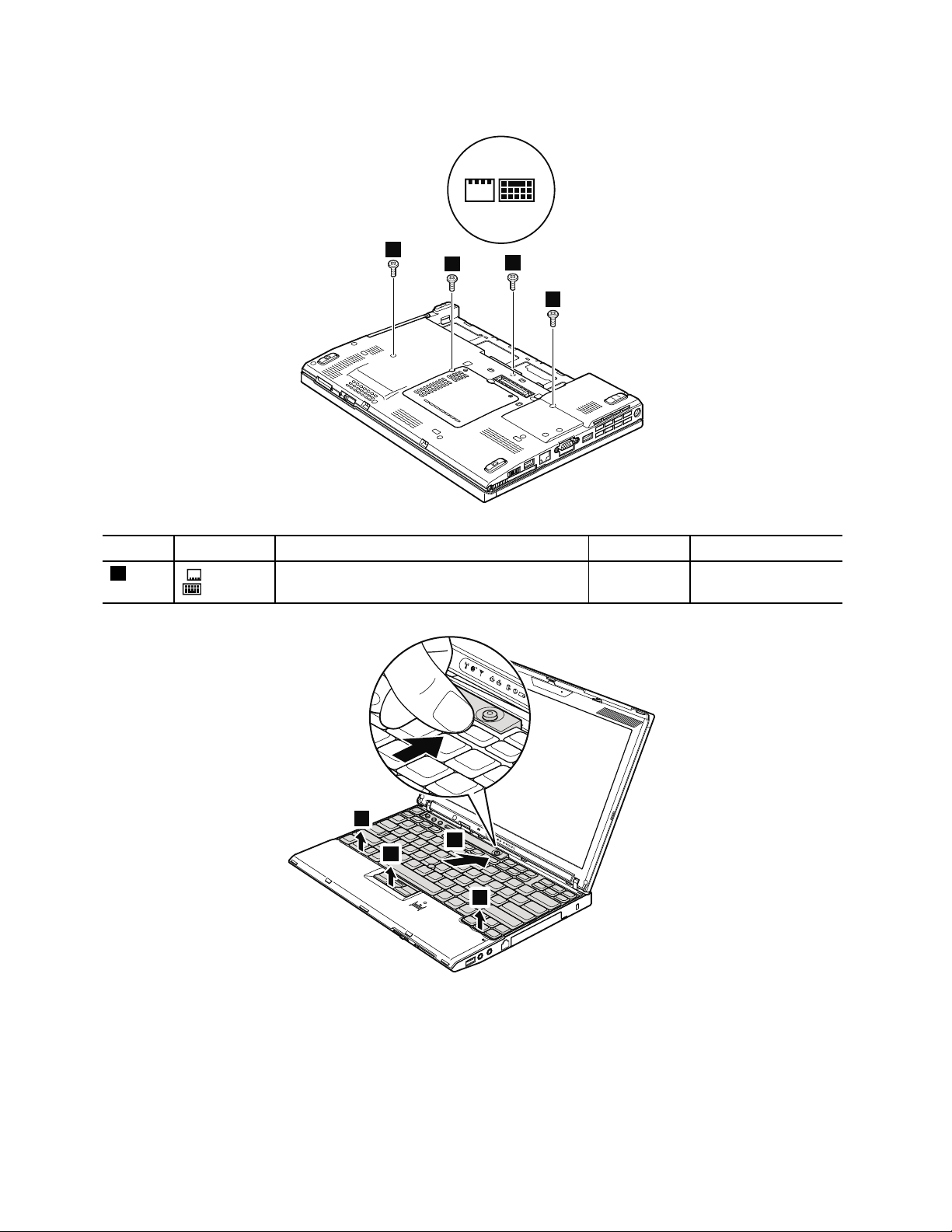
Table12.Removalstepsofkeyboard
1
1
1
1
2
3
3
3
Step
1
Icon
Screw(quantity)Color
M2×5mm,wafer-head,nylon-coated(4)
Black0.181Nm
Torque
(1.85kgf-cm)
78HardwareMaintenanceManual

Table12.Removalstepsofkeyboard(continued)
Liftthekeyboardalittleinthedirectionshownbyarrow4,andthendetachtheconnector5.
Wheninstalling:
1.Attachthekeyboardconnectorrmly.
2.Makesurethatthekeyboardedgesareundertheframeasshowninthisgure.Thenpressthekeystolatchthe
keyboardrmlyinplace.
3.Tomakesurethatthefrontsideofthekeyboardishousedrmly,gentlypressthekeyswithyourthumbs
andtrytoslidethekeyboardtowardyou.
Chapter8.RemovingandreplacingaFRU79

Table12.Removalstepsofkeyboard(continued)
1
1
1
1
1
4.Securethekeyboardbytighteningthescrewsfromthebottomsideofthecomputer.
1050Palmrestorpalmrestwithngerprintreader
Foraccess,removethisFRUinorder:
•“1010Batterypack”onpage71
•“1040Keyboard”onpage77
Note:Inmodelswiththengerprintreader,thesensorisattachedtothepalmrestFRU.Ifthengerprint
readerhasanydefects,youcanreplaceitbytheproceduresgiveninthissection,whicharethesame
forapalmrestwithorwithoutangerprintreader.
Table13.Removalstepsofpalmrest
80HardwareMaintenanceManual

Table13.Removalstepsofpalmrest(continued)
2
3
4
4
4
3
Step
1
Icon
Screw(quantity)Color
M2×5mm,wafer-head,nylon-coated(5)
Black0.181Nm
Torque
(1.85kgf-cm)
Note:Step2isonlyformodelswiththengerprintreader.Formodelswithoutthengerprintreader,skipstep2.
Chapter8.RemovingandreplacingaFRU81

Table13.Removalstepsofpalmrest(continued)
1
2
2
1
Wheninstalling:
1.Inmodelswiththengerprintreader,attachthengerprintreaderconnectorrmlytothesystemboard.
2.Presstheleftandrighttopedgesofthepalmresttotitintoplace.
3.Pushthefrontsideofthepalmrestuntilitclicksintoplace.
4.ClosetheLCDcoverandturnthecomputerover.Thenfastenthevescrewstosecurethepalmrest.
1060Backupbattery
DANGER
Useonlythebatteryspeciedinthepartslistforyourcomputer.Anyotherbatterycouldignite
orexplode.
Foraccess,removetheseFRUsinorder:
•“1010Batterypack”onpage71
•“1040Keyboard”onpage77
•“1050Palmrestorpalmrestwithngerprintreader”onpage80
82HardwareMaintenanceManual

Table14.Removalstepsofbackupbattery
1
3
2
Wheninstalling:
Makesurethatthebatteryconnectorisattachedrmly.
1070PCIExpressMiniCardforwirelessLAN/WiMAX
Foraccess,removetheseFRUsinorder:
•“1010Batterypack”onpage71
•“1040Keyboard”onpage77
•“1050Palmrestorpalmrestwithngerprintreader”onpage80
Chapter8.RemovingandreplacingaFRU83

Table15.RemovalstepsofPCIExpressMiniCardforwirelessLAN/WiMAX
1
2
2
3
FullsizePCIExpressMiniCard:
Instep1,unplugthejacksbyusingtheremovaltoolantennaRFconnector(P/N:08K7159)orpicktheconnectors
withyourngersandgentlyunplugthemindirectionofthearrow.
Note:Somemodelsmighthavetwoantennacablesinstep1.
StepScrew(quantity)Color
2
M2×3mm,wafer-head,nylon-coated(2)
84HardwareMaintenanceManual
Torque
Black0.181Nm
(1.85kgf-cm)

Table15.RemovalstepsofPCIExpressMiniCardforwirelessLAN/WiMAX(continued)
2
1
2
Wheninstalling:
•InmodelswithwirelessLANcardthathastwoantennaconnectors,plugthegraycableintothejacklabeled
MAINorMonthecard,andtheblackcableintothejacklabeledAUXorA.Ifthecomputeryouareservicinghas
threecables,putthewhitecableinthecableprotectiontube.
•InmodelswithwirelessLANcardthathasthreeantennaconnector,plugthegraycable(MAIN)intothejack
labeledTR1,thewhitecable(3rd)intojacklabeledROorTR3,andtheblackcable(AUX)intojacklabeled
TR2onthecard.
HarfsizePCIExpressMiniCard:
Instep
1,unplugthejacksbyusingtheremovaltoolantennaRFconnector(P/N:08K7159)orpicktheconnectors
withyourngersandgentlyunplugthemindirectionofthearrow.
StepScrew(quantity)Color
2
M2×3mm,wafer-head,nylon-coated(2)
Torque
Black0.181Nm
(1.85kgf-cm)
Chapter8.RemovingandreplacingaFRU85

Table15.RemovalstepsofPCIExpressMiniCardforwirelessLAN/WiMAX(continued)
3
2
1
2
Wheninstalling:
PlugthegraycableintothejacklabeledMAINonthecard,andtheblackcableintothejacklabeledAUX.
1080PCIExpressMiniCardforwirelessWAN
Foraccess,removetheseFRUsinorder:
•“1010Batterypack”onpage71
•“1040Keyboard”onpage77
•“1050Palmrestorpalmrestwithngerprintreader”onpage80
Table16.RemovalstepsofPCIExpressMiniCardforwirelessWAN
Instep1,unplugthejacksbyusingtheremovaltoolantennaRFconnector(P/N:08K7159)orpicktheconnectors
withyourngersandgentlyunplugthemindirectionofthearrow.
86HardwareMaintenanceManual

Table16.RemovalstepsofPCIExpressMiniCardforwirelessWAN(continued)
3
StepScrew(quantity)Color
3
Wheninstalling:
PlugtheredcableintothejacklabeledMAINonthecard,andthebluecableintothejacklabeledAUX.
M2×3mm,wafer-head,nylon-coated(2)
Black0.181Nm
Torque
(1.85kgf-cm)
1090IntelTurboMemoryMinicardorWirelessUSBPCIExpress Half-MiniCard
Foraccess,removetheseFRUsinorder:
•“1010Batterypack”onpage71
•“1040Keyboard”onpage77
•“1050Palmrestorpalmrestwithngerprintreader”onpage80
Table17.RemovalstepsofIntelT urboMemoryMinicardorWirelessUSBPCIExpressHalf-MiniCard
Note:Step1isonlyformodelswiththeWirelessUSBPCIExpressHalf-MiniCard.FormodelswiththeIntel
MemoryMinicard,skipstep1.
Instep1,unplugthejacksbyusingtheremovaltoolantennaRFconnector(P/N:08K7159)orpicktheconnectors
withyourngersandgentlyunplugthemindirectionofthearrow.
®
Turbo
Chapter8.RemovingandreplacingaFRU87

Table17.RemovalstepsofIntelTurboMemoryMinicardorWirelessUSBPCIExpressHalf-MiniCard(continued)
1
2
2
3
StepScrew(quantity)Color
2
Wheninstalling:
InmodelswiththeWirelessUSBPCIExpressHalf-MiniCard,plugtheyellowcableintothejackonthecard.
M2×3mm,wafer-head,nylon-coated(2)
Black0.181Nm
Torque
(1.85kgf-cm)
1100Keyboardbezel
Foraccess,removetheseFRUsinorder:
•“1010Batterypack”onpage71
88HardwareMaintenanceManual

•“1040Keyboard”onpage77
1
2
2
2
2
3
3
•“1050Palmrestorpalmrestwithngerprintreader”onpage80
Table18.Removalstepsofkeyboardbezel
StepScrew(quantity)Color
1
Instep2,detachtheclaws.Thenremovethekeyboardbezelinthedirectionshownbyarrow3.
Attention:Whenyouservicethekeyboardbezel,avoidanykindofroughhandling.
Wheninstalling:
M2×5mm,wafer-head,nylon-coated(1)
Black0.181Nm
Torque
(1.85kgf-cm)
Makesurethatalltheclawsareattachedrmly.
1110Monauralspeakerassembly(forX200,X200s,X201s,andX201si)
Foraccess,removetheseFRUsinorder:
•“1010Batterypack”onpage71
•“1040Keyboard”onpage77
•“1050Palmrestorpalmrestwithngerprintreader”onpage80
Chapter8.RemovingandreplacingaFRU89

Table19.Removalstepsofmonauralspeakerassembly(forX200,X200s,X201s,andX201si)
1
2
Wheninstalling:
Makesurethatthespeakerconnectorisattachedrmly.
1120I/Ocardassembly
Foraccess,removetheseFRUsinorder:
•“1010Batterypack”onpage71
•“1040Keyboard”onpage77
•“1050Palmrestorpalmrestwithngerprintreader”onpage80
•“1110Monauralspeakerassembly(forX200,X200s,X201s,andX201si)”onpage89
90HardwareMaintenanceManual

Table20.RemovalstepsofI/Ocardassembly
1
2
3
4
Note:Thecableissecuredwithadouble-facedadhesivetape.
Note:StepaisonlyforThinkPadX201.Fortheothermodels,skipthestepa.
StepScrew(quantity)Color
2
M2×3.5mm,wafer-head,nylon-coated(1)Silver
Torque
0.181Nm
(1.85kgf-cm)
Chapter8.RemovingandreplacingaFRU91

Table20.RemovalstepsofI/Ocardassembly(continued)
5
6
TurntheI/Ocardover,andthendisconnectthecablefromtheip-lockZIFconnector.
1130LCDassembly
Foraccess,removetheseFRUsinorder:
•“1010Batterypack”onpage71
•“1040Keyboard”onpage77
•“1050Palmrestorpalmrestwithngerprintreader”onpage80
•“1070PCIExpressMiniCardforwirelessLAN/WiMAX”onpage83
•“1080PCIExpressMiniCardforwirelessWAN”onpage86
•“1090IntelT urboMemoryMinicardorWirelessUSBPCIExpressHalf-MiniCard”onpage87
•“1100Keyboardbezel”onpage88
Table21.RemovalstepsofLCDassembly
92HardwareMaintenanceManual

Table21.RemovalstepsofLCDassembly(continued)
2
2
StepScrew(quantity)Color
1
M2×5mm,wafer-head,nylon-coated(2)
Black0.181Nm
StepScrew(quantity)Color
2
M2×5mm,wafer-head,nylon-coated(2)
Black0.181Nm
Beforestep3,stripoffthetapessecuringtheantennacables,andreleasethecablesfromthecableguides
oftheframe.
Torque
(1.85kgf-cm)
Torque
(1.85kgf-cm)
StepScrew(quantity)Color
3
M2×5mm,wafer-head,nylon-coated(2)
Torque
Black0.181Nm
(1.85kgf-cm)
Chapter8.RemovingandreplacingaFRU93
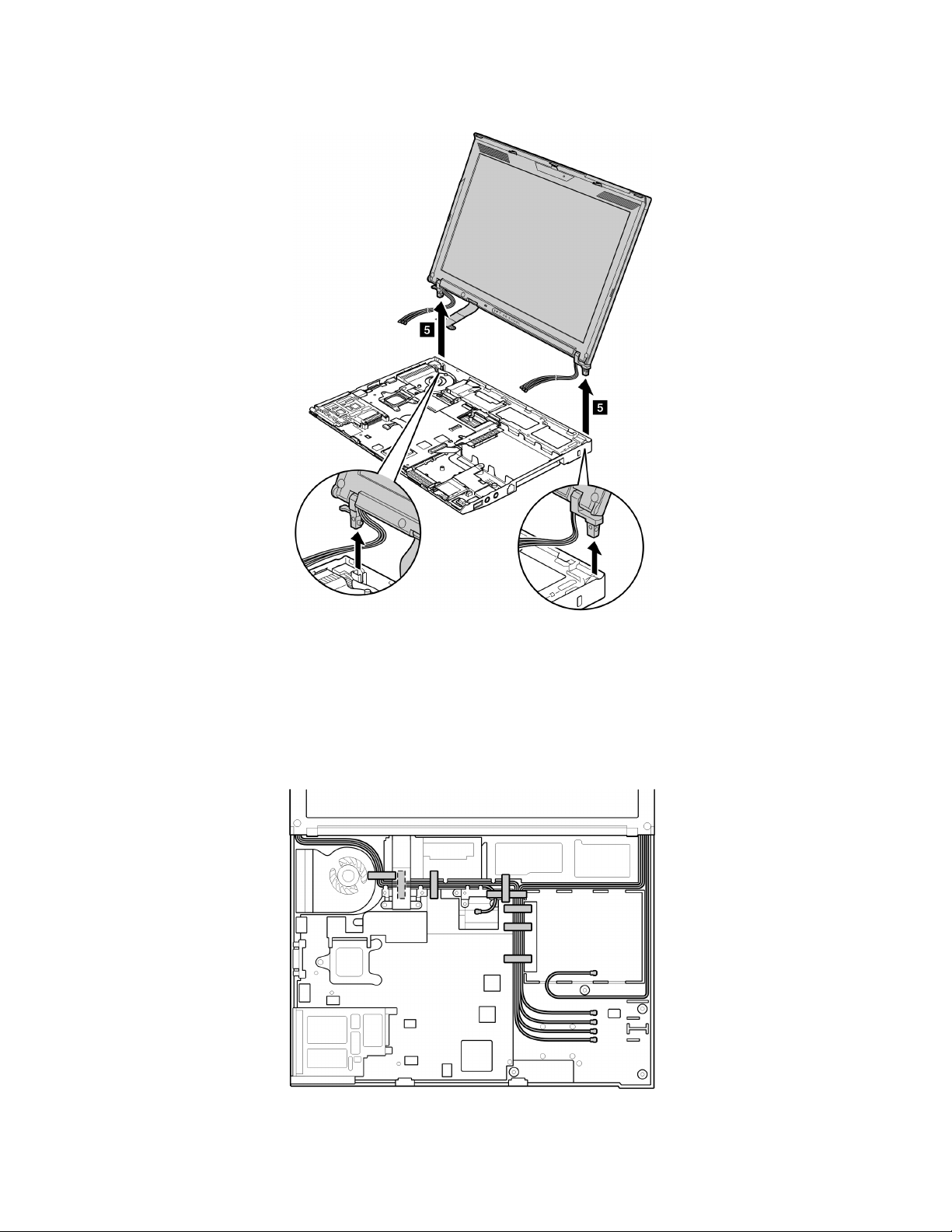
Table21.RemovalstepsofLCDassembly(continued)
Wheninstalling:
1.Routetheantennacablesalongthecableguidesandsecurethemwiththetapes.Asyouroutethecables,
makesurethattheyarenotsubjectedtoanytension.T ensioncouldcausethecablestobedamagedby
thecableguides,orawiretobebroken.
2.MakesurethattheLCDconnectorisattachedrmly.
94HardwareMaintenanceManual
 Loading...