

Lenovo BladeCenter HX5, 7873, 7872, 1910, 1909 Installation And User Manual

BladeCenter HX5 Blade Server
Installation and User's Guide
Machine Types: 7873, 7872, 1910, 1909

Note
Before using this information and the product it supports, read the general information in Appendix B
“Notices” on page 119, the Warranty Information document, and the IBM Safety Information and the
Environmental Notices and User Guide documents on the IBM Documentation CD.
The most recent version of this document is available at http://www.ibm.com/supportportal.
Fifteenth Edition (July 2017)
© Copyright Lenovo 2017.
LIMITED AND RESTRICTED RIGHTS NOTICE: If data or software is delivered pursuant a General Services
Administration “GSA” contract, use, reproduction, or disclosure is subject to restrictions set forth in Contract No.
GS-35F-05925

Contents
Safety . . . . . . . . . . . . . . . . . . iii
Safety statements . . . . . . . . . . . . . . . iv
Chapter 1. Introduction . . . . . . . . . 1
Related documentation. . . . . . . . . . . . . 3
The IBM Documentation CD . . . . . . . . . . . 4
Hardware and software requirements . . . . . 4
Using the Documentation Browser . . . . . . 4
Notices and statements in this document. . . . . . 5
Features and specifications . . . . . . . . . . . 5
What your blade server offers . . . . . . . . . . 8
Reliability, availability, and serviceability
features . . . . . . . . . . . . . . . . . . 10
IBM Systems Director . . . . . . . . . . . . 11
Major components of the blade server . . . . . . 11
Working with a scalable blade complex . . . . . 12
Chapter 2. Power, controls, and
indicators . . . . . . . . . . . . . . . 15
Turning on the blade server . . . . . . . . . . 15
Turning off the blade server . . . . . . . . . . 15
Blade server controls and LEDs . . . . . . . . 16
Scalability indicators . . . . . . . . . . . 19
Blade server connectors - BladeCenter HX5 . . 20
Blade server connectors - IBM MAX5 . . . . 21
Input/output connectors and devices . . . . 21
Chapter 3. Installing optional
devices . . . . . . . . . . . . . . . . . 23
Installation guidelines . . . . . . . . . . . . 23
System reliability guidelines . . . . . . . . 23
Handling static-sensitive devices . . . . . . 23
Removing the blade server from the BladeCenter
chassis . . . . . . . . . . . . . . . . . . 24
Removing the blade server cover . . . . . . . . 25
Disassembling a scalable blade complex . . . . . 26
Removing the 2-node scalability card . . . . . . 27
Removing the IBM MAX5 1-node Scalability
card . . . . . . . . . . . . . . . . . . . 28
Removing an IBM MAX5 . . . . . . . . . . . 29
Installing an expansion unit . . . . . . . . . . 30
Removing an expansion unit . . . . . . . . . . 31
Installing a DIMM - IBM MAX5 . . . . . . . . . 33
Removing a DIMM - IBM MAX5. . . . . . . . . 36
Installing an SSD expansion card . . . . . . . . 37
Removing an SSD expansion card . . . . . . . 38
Installing a solid state drive . . . . . . . . . . 38
Removing a solid state drive . . . . . . . . . . 39
Installing a DIMM - BladeCenter HX5 . . . . . . 40
Removing a DIMM - BladeCenter HX5 . . . . . . 43
Installing a hypervisor key . . . . . . . . . . . 43
Removing a hypervisor key . . . . . . . . . . 46
Installing an I/O expansion card . . . . . . . . 47
Installing a CIOv expansion card . . . . . . 48
Installing a CFFh expansion card . . . . . . 49
Removing an I/O expansion card . . . . . . . . 50
Removing a CFFh expansion card. . . . . . 50
Removing a CIOv expansion card . . . . . . 51
Installing a microprocessor and heat sink. . . . . 51
Installing the 1-node speed burst card . . . . . . 57
Removing the 1-node speed burst card . . . . . 58
Completing the installation . . . . . . . . . . 59
Assembling a scalable blade complex . . . . 60
Installing an IBM MAX5 . . . . . . . . . . 63
Installing the IBM MAX5 1-node Scalability
card . . . . . . . . . . . . . . . . . 67
Installing the blade server cover. . . . . . . 69
Installing a blade server in a BladeCenter
chassis . . . . . . . . . . . . . . . . 70
Updating the blade server configuration . . . 71
Chapter 4. Configuring the blade
server. . . . . . . . . . . . . . . . . . 73
Partitioning a scalable blade complex . . . . . . 74
Using the Setup utility . . . . . . . . . . . . 74
Using the PXE boot agent utility program . . . . . 78
Using the Boot Selection Menu program . . . . . 78
Using the Advanced Settings Utility (ASU) . . . . 79
Updating the Universal Unique Identifier
(UUID). . . . . . . . . . . . . . . . . 79
Updating the DMI/SMBIOS data . . . . . . 81
Using the LSI Logic Configuration Utility
program. . . . . . . . . . . . . . . . . . 83
Updating firmware and device drivers . . . . . . 84
Updating firmware for blade servers operating
as a single partition . . . . . . . . . . . 85
Updating firmware for each blade server
independently. . . . . . . . . . . . . . 85
Chapter 5. Installing the operating
system . . . . . . . . . . . . . . . . . 105
Using the ServerGuide Setup and Installation
CD . . . . . . . . . . . . . . . . . . . . 105
ServerGuide features . . . . . . . . . . . 105
Typical operating-system installation. . . . . 106
© Copyright Lenovo 2017 i

Installing the operating system without using
ServerGuide . . . . . . . . . . . . . . . . 106
Using IBM ServerGuide Scripting Toolkit . . . . . 107
Chapter 6. Accessing the IMM . . . . 109
Potential conflicts with the LAN over USB
interface. . . . . . . . . . . . . . . . . . 109
Resolving conflicts with the IMM LAN over USB
interface. . . . . . . . . . . . . . . . . . 109
Configuring the LAN over USB interface
manually . . . . . . . . . . . . . . . . . 110
Installing the LAN over USB Windows device
driver . . . . . . . . . . . . . . . . . 110
Installing the LAN over USB Linux device
driver . . . . . . . . . . . . . . . . . 111
Chapter 7. Solving problems . . . . . 113
Diagnostic tools overview . . . . . . . . . . . 113
ServerGuide problems . . . . . . . . . . . . 114
Appendix A. Getting help and
technical assistance . . . . . . . . . . 115
Before you call . . . . . . . . . . . . . . . 115
Using the documentation . . . . . . . . . . . 116
Getting help and information from the World Wide
Web . . . . . . . . . . . . . . . . . . . 116
How to send DSA data to IBM . . . . . . . . . 116
Creating a personalized support web page . . . . 116
Software service and support . . . . . . . . . 116
Hardware service and support . . . . . . . . . 117
IBM Taiwan product service . . . . . . . . . . 117
Appendix B. Notices. . . . . . . . . . 119
Trademarks . . . . . . . . . . . . . . . . 119
Important notes. . . . . . . . . . . . . . . 120
Particulate contamination . . . . . . . . . . . 120
Documentation format . . . . . . . . . . . . 121
Telecommunication regulatory statement. . . . . 122
Electronic emission notices . . . . . . . . . . 122
Federal Communications Commission (FCC)
statement . . . . . . . . . . . . . . . 122
Industry Canada Class A emission compliance
statement . . . . . . . . . . . . . . . 122
Avis de conformité à la réglementation
d'Industrie Canada. . . . . . . . . . . . 122
Australia and New Zealand Class A
statement . . . . . . . . . . . . . . . 122
European Union EMC Directive conformance
statement . . . . . . . . . . . . . . . 122
Germany Class A statement . . . . . . . . 123
Japan VCCI Class A statement . . . . . . . 124
Japan Electronics and Information
Technology Industries Association (JEITA)
statement . . . . . . . . . . . . . . . 124
Korea Communications Commission (KCC)
statement . . . . . . . . . . . . . . . 124
Russia Electromagnetic Interference (EMI)
Class A statement . . . . . . . . . . . . 124
People's Republic of China Class A electronic
emission statement . . . . . . . . . . . 124
Taiwan Class A compliance statement . . . . 125
Index . . . . . . . . . . . . . . . . . . 127
ii BladeCenter HX5 Blade ServerInstallation and User's Guide
Safety
Before installing this product, read the Safety Information.
Antes de instalar este produto, leia as Informações de Segurança.
Læs sikkerhedsforskrifterne, før du installerer dette produkt.
Lees voordat u dit product installeert eerst de veiligheidsvoorschriften.
Ennen kuin asennat tämän tuotteen, lue turvaohjeet kohdasta Safety Information.
Avant d'installer ce produit, lisez les consignes de sécurité.
Vor der Installation dieses Produkts die Sicherheitshinweise lesen.
Prima di installare questo prodotto, leggere le Informazioni sulla Sicurezza.
Les sikkerhetsinformasjonen (Safety Information) før du installerer dette produktet.
Antes de instalar este produto, leia as Informações sobre Segurança.
© Copyright Lenovo 2017 iii
Antes de instalar este producto, lea la información de seguridad.
Läs säkerhetsinformationen innan du installerar den här produkten.
Safety statements
These statements provide the caution and danger information that is used in this documentation.
Important: Each caution and danger statement in this documentation is labeled with a number. This number
is used to cross reference an English-language caution or danger statement with translated versions of the
caution or danger statement in the Safety Information document.
For example, if a caution statement is labeled “Statement 1,” translations for that caution statement are in the
Safety Information document under “Statement 1.”
Be sure to read all caution and danger statements in this documentation before you perform the procedures.
Read any additional safety information that comes with your system or optional device before you install the
device.
Statement 1
iv BladeCenter HX5 Blade ServerInstallation and User's Guide
DANGER
Electrical current from power, telephone, and communication cables is hazardous.
To avoid a shock hazard:
• Do not connect or disconnect any cables or perform installation, maintenance, or reconfiguration
of this product during an electrical storm.
• Connect all power cords to a properly wired and grounded electrical outlet.
• Connect to properly wired outlets any equipment that will be attached to this product.
• When possible, use one hand only to connect or disconnect signal cables.
• Never turn on any equipment when there is evidence of fire, water, or structural damage.
• Disconnect the attached power cords, telecommunications systems, networks, and modems
before you open the device covers, unless instructed otherwise in the installation and
configuration procedures.
• Connect and disconnect cables as described in the following table when installing, moving, or
opening covers on this product or attached devices.
To Connect: To Disconnect:
1. Turn everything OFF.
2. First, attach all cables to devices.
3. Attach signal cables to connectors.
4. Attach power cords to outlet.
5. Turn device ON.
1. Turn everything OFF.
2. First, remove power cords from outlet.
3. Remove signal cables from connectors.
4. Remove all cables from devices.
Statement 2
CAUTION:
When replacing the lithium battery, use only IBM Part Number 33F8354 or an equivalent type battery
recommended by the manufacturer. If your system has a module containing a lithium battery, replace
it only with the same module type made by the same manufacturer. The battery contains lithium and
can explode if not properly used, handled, or disposed of.
Do not:
• Throw or immerse into water
• Heat to more than 100°C (212°F)
• Repair or disassemble
Dispose of the battery as required by local ordinances or regulations.
Note:
© Copyright Lenovo 2017 v
Statement 12
CAUTION:
The following label indicates a hot surface nearby.
Statement 21
CAUTION:
Hazardous energy is present when the blade is connected to the power source. Always replace the
blade cover before installing the blade.
UL regulatory information
This device is for use only with supported blade chassis.
vi
BladeCenter HX5 Blade ServerInstallation and User's Guide

Chapter 1. Introduction
The IBM BladeCenter HX5 Type 7873, 7872, 1910, and 1909 blade servers are high-density, scalable blade
servers ideally suited for high performance and virtualized environments. A BladeCenter HX5 can be
combined with the IBM MAX5 for BladeCenter expansion blade to provide memory expansion for medium to
large businesses.
The IBM BladeCenter HX5 Type 7873, 7872, 1910, and 1909 blade servers support the following
components:
• Up to two multi-core microprocessors
• Up to 16 memory modules (DIMMs)
Note: Combining a BladeCenter HX5 and an IBM MAX5 expansion blade supports up to 40 DIMMs.
• Up to two internal solid state drives (SSDs)
• Expansion devices, such as:
– Horizontal-compact-form-factor (CFFh) expansion cards
– Vertical-combination-I/O (CIOv) expansion cards
In addition, you can combine two BladeCenter HX5 blade servers to form a scalable blade complex.
Combining two BladeCenter HX5 blade servers in a scalable blade complex provides for FlexNode
partitioning. With FlexNode partitioning, you can deploy the blade servers as a single server or as two
independent servers, without changing the physical configuration. The ability to switch between singlepartition mode and stand-alone mode is provided through the advanced management module web interface.
For more information about scalable blade complexes and FlexNode partitioning, see “Working with a
scalable blade complex” on page 12.
Note: You can combine two BladeCenter HX5 blade servers to form a scalable blade complex. You can also
combine a single BladeCenter HX5 blade server with an IBM MAX5 expansion blade for expanded memory
access. You cannot attach an IBM MAX5 to a scalable blade complex.
For more information about the advanced management module web interface, see the http://www.ibm.com/
systems/ support/supportsite.wss/docdisplay? brandind=5000008&lndocid=MIGR-5073887.
The BladeCenter HX5 blade server is supported in the following BladeCenter chassis:
• IBMBladeCenter H
• IBMBladeCenter HT
• IBMBladeCenter S
For the latest information about the BladeCenter chassis that support the BladeCenter HX5 blade server, see
http://www.ibm.com/ servers/eserver/serverproven/compat/us/.
This Installation and User's Guide provides information about setting up the blade server, such as:
• Starting and configuring the blade server
• Installing optional hardware devices
• Installing the operating system
• Performing basic troubleshooting of the blade server
Packaged with the blade server are software CDs that help you to configure hardware, install device drivers,
and install the operating system.
© Copyright Lenovo 2017 1
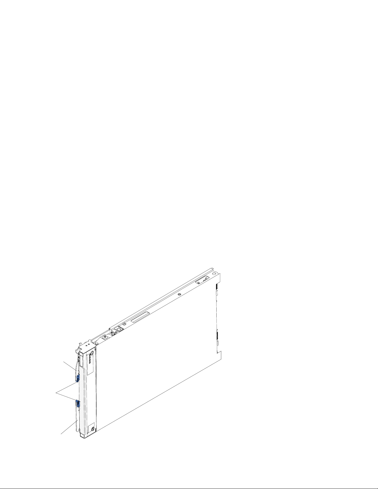
To download the latest firmware and device drivers, complete the following steps.
Release
handle
Release
buttons
Release
handle
Note: Changes are made periodically to the IBM website. The actual procedure might vary slightly from what
is described in this document.
1. Go to http://www.ibm.com/supportportal/.
2. Under Product support, click BladeCenter.
3. Under Popular links, click Software and device drivers.
4. Click BladeCenter HX5 to display the matrix of downloadable files for the blade server.
The blade server comes with a limited warranty. For information about the terms of the warranty and getting
service and assistance, see the Warranty Information document for your blade server. This document is
available on the IBMDocumentation CD. You can obtain up-to-date information about the blade server at
http://www.ibm.com/systems/bladecenter.
The blade server might have features that are not described in the documentation that comes with the blade
server. The documentation might be updated occasionally to include information about those features.
Technical updates might also be available to provide additional information that is not included in the blade
server documentation.
To obtain the latest and most up-to-date documentation for this product, go to http://publib.boulder.ibm.
com/infocenter/bladectr/documentation/index.jsp.
You can subscribe to information updates that are specific to your blade server at http://www.ibm.com/
support/mynotifications/.
The model number and serial number are on the ID label that is located next to the power LED on the blade
server bezel. They are also on a label on the side of the blade server that is visible when the blade server is
not in the BladeCenter chassis.
2 BladeCenter HX5 Blade ServerInstallation and User's Guide

A set of blank labels for your blade server comes with the BladeCenter chassis. When you install the blade
server in the BladeCenter chassis, write identifying information about the blade server on a label. Then place
the label on the BladeCenter chassis bezel. See the documentation for your BladeCenter chassis for
recommended label placement.
Important: Do not place the label on the blade server itself or in any way block the ventilation holes on the
blade server.
In addition, the system service label, which is on the cover of the server, provides a QR code for mobile
access to service information. You can scan the QR code using a QR code reader and scanner with a mobile
device and get quick access to the IBM Service Information website. The IBM Service Information website
provides additional information for parts installation and replacement videos, and error codes for server
support.
The following illustration shows the QR code (http://ibm.co/114H7dt):
Figure 1. QR code
Related documentation
Use this information to identify and locate related blade server documentation.
This Installation and User's Guide contains general information about the blade server, including how to
install supported optional devices and how to configure the blade server. The following documentation is
also available:
• Problem Determination and Service Guide
This document contains information to help you solve problems yourself, and it contains information for
service technicians.
• Safety Information
This document contains translated caution and danger statements. Each caution and danger statement
that appears in the documentation has a number that you can use to locate the corresponding statement
in your language in the Safety Information document.
• Warranty Information
This document contains information about the terms of the warranty.
• Environmental Notices and User Guide
This document contains translated environmental notices.
• Integrated Management Module User's Guide
This document explains how to use the functions of the IMM that is installed in an IBM server. The IMM
works with IBMSystem x Server Firmware to provide systems-management capability for System x and
BladeCenter servers.
• Advanced Management Module User's Guide
This document provides information about configuring the advanced management module and managing
components that are installed in an IBM® BladeCenter® chassis.
Chapter 1. Introduction 3

• Advanced Management Module Command-Line Interface Reference Guide
This document explains how to use the advanced management module command-line interface (CLI) to
directly access BladeCenter management functions. The command-line interface also provides access to
the text-console command prompt on each blade server through a Serial over LAN (SOL) connection.
• Advanced Management Module Messages Guide
This document provides a complete list of all non-device specific events and recommended actions,
sorted by event ID. Device-specific event information is available in the Problem Determination and
Service Guide.
In addition to the documentation in this library, be sure to review the Planning and Installation Guide for your
BladeCenter chassis for information to help you prepare for system installation and configuration.
To check for updated documentation, complete the following steps.
1. Go to http://www.ibm.com/supportportal/.
2. Under Product support, click BladeCenter.
3. Under Popular links, click Publications lookup.
4. From the Product family menu, select BladeCenter HX5 .
You can also find documentation that is related to BladeCenter products at http://publib.boulder.ibm.com/
infocenter/bladectr/documentation/index.jsp.
The IBM Documentation CD
The IBM Documentation CD contains documentation for your blade server in Portable Document Format
(PDF). It includes the IBM Documentation Browser to help you find information quickly.
You can run the IBM Documentation CD on any personal computer that meets the hardware and software
requirements.
Hardware and software requirements
Use this information to determine the minimum hardware and software requirements for the blade server.
The IBM Documentation CD requires the following minimum hardware and software:
• Microsoft Wndows XP, Windows 2000, or Red Hat Enterprise Linux 5 Server
• 100 MHz microprocessor
• 32 MB of RAM
• Adobe Acrobat Reader 3.0 (or later) or xpdf, which comes with Linux operating systems
Using the Documentation Browser
Use these instructions to start the Documentation Browser.
Use the Documentation Browser to browse the contents of the CD, read brief descriptions of the documents,
and view documents, using Adobe Acrobat Reader or xpdf. The Documentation Browser automatically
detects the regional settings in use in your system and displays the documents in the language for that
region (if available). If a document is not available in the language for that region, the English-language
version is displayed.
Use one of the following procedures to start the Documentation Browser:
• If Autostart is enabled, insert the CD into the CD drive. The Documentation Browser starts automatically.
4
BladeCenter HX5 Blade ServerInstallation and User's Guide

• If Autostart is disabled or is not enabled for all users, use one of the following procedures:
– If you are using a Windows operating system, insert the CD into the CD or DVD drive and click Start →
Run. In the Open field, type
e:\win32.bat
where e is the drive letter of the CD or DVD drive, and click OK.
– If you are using Red Hat Linux, insert the CD into the CD or DVD drive; then, run the following
command from the /mnt/cdrom directory:
sh runlinux.sh
Select your blade server from the Product menu. The Available Topics list displays all the documents for
your blade server. Some documents might be in folders. A plus sign (+) indicates each folder or document
that has additional documents under it. Click the plus sign to display the additional documents.
When you select a document, a description of the document is displayed under Topic Description. To select
more than one document, press and hold the Ctrl key while you select the documents. Click View Book to
view the selected document or documents in Acrobat Reader or xpdf. If you selected more than one
document, all the selected documents are opened in Acrobat Reader or xpdf.
To search all the documents, type a word or word string in the Search field and click Search. The
documents in which the word or word string appears are listed in order of the most occurrences. Click a
document to view it. Press Ctrl+F to use the Acrobat search function, or press Alt+F to use the xpdf search
function within the document.
Click Help for detailed information about using the Documentation Browser.
Notices and statements in this document
Use this information to understand the most common documentation notices and statements and how they
are used.
The caution and danger statements in this document are also in the multilingual Safety Information
document, which is on the IBMDocumentation CD. Each statement is numbered for reference to the
corresponding statement in the Safety Information document.
The following notices and statements are used in this document:
• Note: These notices provide important tips, guidance, or advice.
• Important: These notices provide information or advice that might help you avoid inconvenient or
problem situations.
• Attention: These notices indicate possible damage to programs, devices, or data. An attention notice is
placed just before the instruction or situation in which damage might occur.
• Caution: These statements indicate situations that can be potentially hazardous to you. A caution
statement is placed just before the description of a potentially hazardous procedure step or situation.
• Danger: These statements indicate situations that can be potentially lethal or hazardous to you. A danger
statement is placed just before the description of a potentially lethal or hazardous procedure step or
situation.
Features and specifications
Use this table to view specific information about the blade server, such as blade server hardware features
and the dimensions of the blade server.
Chapter 1. Introduction 5

Notes:
1. Power, cooling, removable-media drives, external ports, and advanced systems management are
provided by the BladeCenter chassis.
2. The operating system in the blade server must provide USB support for the blade server to recognize
and use USB media drives and devices. The BladeCenter chassis uses USB for internal communications
with these devices.
The following table is a summary of the features and specifications of the BladeCenter HX5 blade server.
6
BladeCenter HX5 Blade ServerInstallation and User's Guide

Table 1. Features and specifications
Microprocessor: Up to 2 multi-core
IntelXeon processors.
Note: Use the Setup utility to
determine the type and speed of the
microprocessors in the blade server.
Memory:
• 16 dual inline memory module
(DIMM) connectors
• Type: Very Low Profile (VLP)
double-data rate (DDR3) DRAM.
Supports 2 GB, 4 GB, 8 GB, 16
GB, and 32 GB DIMMs with up to
512 GB of total memory on the
system board
If two BladeCenter HX5 blade servers
are assembled into a scalable blade
complex, up to 1 TB is available to
the scalable blade complex.
If the IBM MAX5 is installed:
• Supports up to 40 dual inline
memory module (DIMM)
connectors for up to 1.25 TB of
total memory.
Note: The BladeCenter HX5 blade
server supports memory sparing.
Integrated functions:
• Horizontal-compact-form-factor
(CFFh) expansion card interface
• Vertical-combination-I/O (CIOv)
expansion card interface
• Local service processor:
integrated management module
(IMM) with Intelligent Platform
Management Interface (IPMI)
firmware
• Integrated Matrox G200eV video
controller
• Broadcom BCM5709S dual-port
Gigabit Ethernet controller
• Integrated keyboard/video/
mouse (cKVM) controller through
IMM
• Light path diagnostics
• RS-485 interface for
communication with the
management module
• Automatic server restart (ASR)
• USB 2.0 for communication with
cKVM and removable media
drives (an external USB port is
not supported)
• Serial over LAN (SOL)
• Wake on LAN (WOL)
• Redundant buses for
communication with keyboard,
mouse, and removable media
drives
Predictive Failure Analysis (PFA)
alerts:
• Microprocessors
• Memory
Electrical input: 12 V dc
Size:
Single BladeCenter HX5 blade
server:
• Height: 24.5 cm (9.7 in) (6U)
• Depth: 44.6 cm (17.6 in)
• Width: 2.9 cm (1.14 in)
• Maximum weight: 5.6 kg (12.38
lb)
2 BladeCenter HX5 blade servers
assembled into a scalable blade
complex:
• Height: 24.5 cm (9.7 in) (6U)
• Depth: 44.6 cm (17.6 in)
• Width: 5.8 cm (2.28 in)
• Maximum weight: 11.23 kg
(24.76 lb)
Environment:
• Air temperature:
– Blade server on: 10°C to 35°C
(50°F to 95°F). Altitude: 0 m to
914.4 m (0 ft to 3000 ft)
– Blade server on: 10°C to 32°C
(50°F to 89.6°F). Altitude: 914.4
m to 2133.6 m (3000 ft to 7000 ft)
– Blade server off: 10°C to 43°C
(50°F to 109.4°F). Altitude: 914.4
m to 2133.6 m (3000 ft to 7000 ft)
– Blade server shipping: -40°C to
60°C (-40°F to 140°F)
• Humidity:
– Blade server on: 8% to 80%
– Blade server off: 8% to 80%
– Blade server storage: 5% to 80%
– Blade server shipping: 5% to
100%
• Particulate contamination
Attention: Airborne particulates and
reactive gases acting alone or in
combination with other
environmental factors such as
humidity or temperature might pose
a risk to the server. For information
about the limits for particulates and
gases, see “Particulate
contamination” on page 120.
A BladeCenter HX5 blade server
combined with an IBM MAX5
expansion blade:
• Height: 24.5 cm (9.7 in) (6U)
• Depth: 44.6 cm (17.6 in)
• Width: 5.8 cm (2.28 in)
• Maximum weight: 9.5 kg (21.0 lb)
Chapter 1. Introduction 7

What your blade server offers
Your blade server offers features, such as the integrated management module, storage disk drive support,
IBM® Systems Director, IBM Enterprise X-Architecture, microprocessor technology, integrated network
support, I/O expansion, large system-memory capacity, light path diagnostics LEDs, PCI Express, and
power throttling.
• Integrated management module (IMM)
The integrated management module (IMM) combines service processor functions, video controller, the
remote presence, and blue-screen capture features in a single chip. The IMM provides advanced serviceprocessor control, monitoring, and alerting function. If an environmental condition exceeds a threshold or
if a system component fails, the IMM lights LEDs to help you diagnose the problem, records the error in
the IMM event log, and alerts you to the problem.
Optionally, the IMM also provides a virtual presence capability for remote server management capabilities.
The IMM provides remove server management through industry-standard interfaces:
– Intelligent Platform Management Interface (IPMI) version 2.0
– Simple Network Management Protocol (SNMP) version 3.0
– Common Information Model (CIM)
– web browser.
For more information, see Chapter 6 “Accessing the IMM” on page 109.
• Dynamic System Analysis (DSA)
IBM Dynamic Systems Analysis (DSA) collects and analyses system information to aid in diagnosing
server problems. DSA collects the following information about the server:
– Drive health information
– Event logs for ServeRAID controllers and service processors
– Hardware inventory, including PCI and USB information
– Installed applications and hot fixes
– Kernel modules
– Light path diagnostics status
– Network interface and settings
– Performance data and details about processes that are running
– RAID and controller configuration
– Service processor (integrated management module) status and configuration
– System configuration
– Vital product data and firmware information
DSA creates a DSA log, which is a chronologically ordered merge of the system-event log (as the IPMI
event log), the integrated management module (IMM) chassis-event log (as the ASM event log), and the
operating-system event logs. You can send the DSA log as a file to IBM service or view the information as
a text file or HTML file.
For more information, see the Problem Determination and Service Guide.
• Hard disk drive support
The blade server supports up to two solid state drives (SSDs). You can implement RAID 0 or RAID 1 for
the SSDs.
• IBM ServerGuide Setup and InstallationCD
8
BladeCenter HX5 Blade ServerInstallation and User's Guide

The ServerGuide Setup and Installation CD, which you can download from the web, provides programs to
help you set up the server and install a Windows operating system. The ServerGuide program detects
installed optional hardware devices and provides the correct configuration programs and device drivers.
For more information, see “Using the ServerGuide Setup and Installation CD” on page 105.
• IBM Systems Director
IBM Systems Director is a platform-management foundation that streamlines the way you manage
physical and virtual systems in a heterogeneous environment. By using industry standards, IBM Systems
Director supports multiple operating systems and virtualization technologies for IBM and non-IBM x86
platforms. For more information, see http://publib.boulder.ibm.com/ infocenter/director/v6r2x/index.jsp.
• IBM Enterprise X-Architecture
IBM Enterprise X-Architecture technology combines proven, innovative IBM designs to make your x86-
processor-based blade server powerful, scalable, and reliable. For more information, see http://www.ibm.
com/ systems/x/hardware/enterprise/xarchitecture.html.
• Microprocessor technology
The blade server supports up to two multi-core IntelXeon microprocessors. For more information about
supported microprocessors and their part numbers, see the Problem Determination and Service Guide.
Note: The optional microprocessors that IBM supports are limited by the capacity and capability of the
server. Any microprocessors that you install must have the same specifications as the microprocessors
that came with the servers.
• Integrated network supportAll blade server models come with an integrated Broadcom dual-port
Gigabit Ethernet controller. The controller supports connections to a 10 Mbps, 100 Mbps, or 1000 Mbps
network through an Ethernet-compatible switch module in the BladeCenter chassis. The controller also
supports Wake on LAN® technology.
• I/O expansion
The blade server has connectors on the system board for optional expansion cards for adding more
network communication capabilities to the blade server.
• Large system-memory capacity
The blade server system board supports up to 256 GB of system memory. The memory controller
provides support for up to 16 industry-standard registered ECC DDR3 on Very Low Profile (VLP) form
factor DIMMs installed on the system board. For the most current list of supported DIMMs, see the
ServerProven list at http://www.ibm.com/ servers/eserver/serverproven/compat/us/.
Note: If two BladeCenter HX5 blade servers are assembled into a scalable blade complex, up to 512 GB
of system memory is available to the scalable blade complex.
• Server expansion
You can combine two blade servers together to form a scalable blade complex. Through the advanced
management module web interface, you can then configure the scalable blade complex to function as a
single hardware partition, which is single server with up to four multi-core microprocessors and up to 512
GB of system memory.
Combining two blade servers into a scalable blade complex provides you with implementation flexibility
through FlexNode partitioning. Through the advanced management module, you can implement the
scalable blade complex as a single server or as two independent servers without changing the physical
setup of the blade servers. For more information about scalable blade complexes and FlexNode
partitioning, see “Working with a scalable blade complex” on page 12.
• Light path diagnostics
Light path diagnostics provides light-emitting diodes (LEDs) to help you diagnose problems. For more
information, see the Problem Determination and Service Guide.
Chapter 1. Introduction 9

In addition, scalability indicators are available through the front bezel. These indicators enable you to tell
whether BladeCenter HX5 blade servers are operating independently or as a single hardware partition.
• Mobile access to IBM Service Information website
The server provides a QR code on the system service label, which is on the cover of the server, that you
can scan using a QR code reader and scanner with a mobile device to get quick access to the IBM
Service Information website. The IBM Service Information website provides additional information for
parts installation and replacement videos, and error codes for server support. For the QR code, see QR
code information on page Chapter 1 “Introduction” on page 1.
• PCI Express
PCI Express is a serial interface that is used for chip-to-chip interconnect and expansion adapter
interconnect. With the blade expansion connector, you can add optional I/O and storage devices.
• Power throttling
Each blade server is powered by two Enterprise Voltage Regulator-Down (EVRD) 11.0 voltage regulators.
By enforcing a power policy known as power-domain oversubscription, the BladeCenter chassis can
share the power load between two power modules to ensure sufficient power for each device in the
BladeCenter chassis. This policy is enforced when the initial power is applied to the BladeCenter chassis
or when a blade server is inserted into the BladeCenter chassis.
The following settings for this policy are available:
– Power module redundancy
– Power module redundancy with blade throttling allowed
– Basic power management
You can configure and monitor the power environment by using the advanced management module. For
more information about configuring and using power throttling, see the Advanced Management Module
User's Guide (available at http://publib.boulder.ibm.com/infocenter/bladectr/documentation/index.jsp) or
http://www.ibm.com/supportportal/.
Reliability, availability, and serviceability features
Three of the most important features in server design are reliability, availability, and serviceability (RAS).
These RAS features help to ensure the integrity of the data that is stored in the blade server, the availability of
the blade server when you need it, and the ease with which you can diagnose and correct problems.
The blade server has the following RAS features:
• Customer upgrade of flash ROM-resident code and diagnostics
• Power policy 24-hour support center
• Vital product data (VPD) on memory
• Processor presence detection
• Advanced Configuration and Power Interface (ACPI)
• Automatic server restart (ASR)
• Built-in diagnostics using DSA Preboot, which is stored in integrated USB memory.
• Built in monitoring for temperature, voltage, and hard disk drives
• Customer support center 24 hours per day, 7 days a week.
• Customer-upgradeable Unified Extensible Firmware Interface (UEFI) code and diagnostics
• ECC protection on the L2 cache
• Error codes and messages
• Integrated management module (IMM)
• Light path diagnostics
• Memory parity testing
1. Service availability varies by country. Response time varies depending on the number and nature of incoming calls.
1
10
BladeCenter HX5 Blade ServerInstallation and User's Guide

• Registered ECC DDR3 memory
• Microprocessor built-in self-test (BIST) during power-on self-test (POST)
• Microprocessor serial number access
• PCI PMI 2.2
• PCI Express 1.0a
• POST
• ROM-resident diagnostics
• Service processor that communicates with the advanced management module to enable remote blade
server management
• System-error logging
• Wake on LAN capability
• Wake on PCI (PME) capability
• Wake on USB 2.0 capability
IBM Systems Director
IBM Systems Director is a platform-management foundation that streamlines the way you manage physical
and virtual systems in a heterogeneous environment.
By using industry standards, IBM Systems Director supports multiple operating systems and virtualization
technologies in IBM and non-IBM x86 platforms.
Through a single user interface, IBM Systems Director provides consistent views for viewing managed
systems, determining how these systems relate to one another, and identifying their statuses, helping to
correlate technical resources with business needs. A set of common tasks that are included with IBM
Systems Director provides many of the core capabilities that are required for basic management, which
means instance business value. These common tasks include discovery, inventory, configuration, system
health, monitoring, updates, event notification, and automation for managed systems.
The IBM Systems Director web and command-line interfaces provide a consistent interface that is focused
on driving these common tasks and capabilities:
• Discovering, navigating, and visualizing systems on the network with the detailed inventory and
relationships to the other network resources
• Notifying users of problems that occur on systems and the ability to isolate sources of the problems
• Notifying users when systems need updates and distributing and installing updates on a schedule
• Analyzing real-time data for systems and setting critical thresholds that notify the administrator of
emerging problems
• Configuring settings of a single system and creating a configuration plan that can apply those settings to
multiple systems
• Updating installed plug-ins to add new features and functions to the base capabilities
• Managing the life cycles of virtual resources
For more information about IBM Systems Director, see the documentation at http://publib.boulder.ibm.com/
infocenter/director/v6r2x/index.jsp, and the IBMxSeries Systems Management website at http://www.ibm.
com/systems/management/, which presents an overview of IBM Systems Management and IBM Systems
Director.
Major components of the blade server
Use this information to locate the major components on the blade server. The major components of the
blade server include field replaceable units (FRUs), customer replaceable units (CRUs), and optional devices.
Chapter 1. Introduction 11
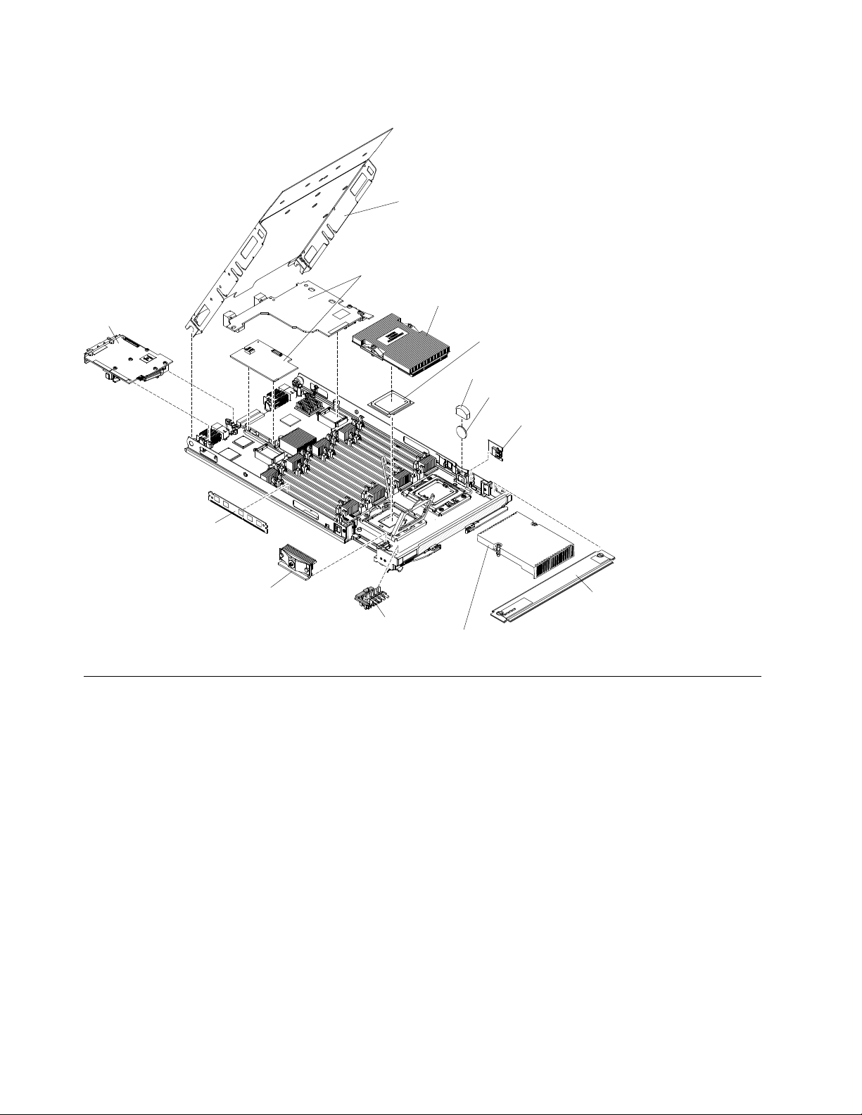
The following illustration shows the major components of the blade server.
Cover
Expansion
cards
SSD
expansion
card
Heat sink
Microprocessor
heat sink filler
DIMM
Microprocessor
Battery cover
Battery
Embedded
hypervisor
interposer
Scaling
card filler
Front
access
cover
Operator
control
panel
Working with a scalable blade complex
You can assemble two BladeCenter HX5 blade servers together to create a scalable blade complex.
A scalable blade complex supports the following implementation modes:
• Single partition. The complex functions as a single server that contains up to four multi-core processors
and up to 32 DIMMs. When the complex is implemented as a single hardware partition, the leftmost blade
server (as installed in a BladeCenter chassis) is called the primary blade server. The blade server on the
right is called the secondary blade server.
12
BladeCenter HX5 Blade ServerInstallation and User's Guide
Primary
blade
server
Secondary
blade
server
• Multiple partitions (independent partitions). The blade servers are combined into a scalable blade
complex, but each of the blade servers is set up as a single partition.
• Stand-alone mode. The blade servers operate independently.
Important: If you install the primary blade server of a scalable blade complex in blade server bay 7 of a
BladeCenter H Type 8852 chassis, the secondary blade server is installed in blade server bay 8. The primary
blade server receives power from power domain 1 of the chassis and the secondary blade server receives
power from power domain 2 of the chassis. The following situations can occur if there is a power loss to
either power domain, depending on how the scalable blade complex is implemented:
• If the scalable blade complex is implemented in single partition mode, a loss of power to power domain 1
or power domain 2 results in both blade servers in the scalable blade complex going down.
• If the scalable blade complex is implemented in stand-alone mode, a loss of power to power domain 1
results in the entire scalable blade complex going down. A loss of power to power domain 2 results in the
blade server installed in blade server bay 8 going down, but the blade server installed in blade server bay
7 continues to function.
With FlexNode processing, you can toggle between single partition mode and stand-alone mode without
having to modify the physical setup of the blade servers. To toggle between modes, use the advanced
management module web interface.
For example, assume that you have created a scalable blade complex and defined that complex as a single
partition through the advanced management module web interface:
• You can toggle the scalable blade complex to stand-alone mode through the web interface. In standalone mode, you can install a different operating system on each blade server and run different
applications on each blade server.
• You can then toggle the blade server complex back to a single partition and run applications that take
advantage to up to 4 processors and 32 DIMMs. The operating system that is in use is the operating
system of the primary blade server.
• Later, you can toggle the complex back to stand-alone mode again to gain access to the operating
system on the secondary blade server.
Chapter 1. Introduction 13

Single partition mode considerations
The following considerations apply to the blade servers in a scalable blade complex that operates as a single
hardware partition:
• All UEFI settings (set through the Setup utility) should be the same on both blade servers. If they are not,
the settings that are defined for the primary blade server replace the UEFI settings on the secondary
server.
Note: When you upgrade the firmware for the blade servers operating in single partition mode, you only
have to upgrade the primary blade server. The firmware on the secondary blade server is automatically
updated. See “Using the Setup utility” on page 74 for more information about the Setup utility.
• The primary blade server has access to the SSDs on the secondary blade server. However, the SSDs on
the primary blade server cannot be combined with the SSDs on the secondary blade server to form a
single RAID array. RAID arrays can be formed only using the SSDs within a blade server.
• The primary blade server has access to any I/O expansion cards that are installed in the secondary blade
server. However, the I/O expansion cards in the secondary blade server cannot be used for a Serial Over
LAN connection.
• The primary blade server has access to any expansion blades that are installed on the secondary blade
server.
Important: An expansion blade installed on the secondary blade server cannot be used for a Serial Over
LAN connection.
• If you press the power button on one blade server, both blade servers in the partition either power up or
power down, depending on the state of the blade servers when you press the power button.
14
BladeCenter HX5 Blade ServerInstallation and User's Guide

Chapter 2. Power, controls, and indicators
Use this information to view power features, turn on and turn off the blade server, and view the functions of
the controls and indicators.
Turning on the blade server
After you connect the blade server to power through the BladeCenter chassis, the blade server can be
started in any of the following ways.
• You can press the power button on the front of the blade server (see “Blade server controls and LEDs” on
page 16) to start the blade server. The power button works only if local power control is enabled for the
blade server. Local power control is enabled and disabled through the advanced management module
web interface.
Notes:
1. Wait until the power LED on the blade server flashes slowly before you press the power button. While
the service processor in the blade server is initializing and synchronizing with the advanced
management module, the power-on LED flashes rapidly, and the power-control button on the blade
server does not respond. This process can take approximately 90 seconds after the blade server has
been installed.
2. While the blade server is starting, the power LED on the front of the blade server is lit and does not
flash. See “Blade server controls and LEDs” on page 16 for the power LED states.
• If a power failure occurs, the BladeCenter chassis and the blade server can be configured through the
advanced management module web interface to start automatically when power is restored.
• You can turn on the blade server through the advanced management module web interface. For more
information about the advanced management module web interface, see the IBM BladeCenter Advanced
Management Module: User's Guide.
• You can turn on the blade server through the Wake on LAN feature. The blade server must be connected
to power (the power-on LED is flashing slowly), the blade server must be communicating with the
advanced management module, the operating system must support the Wake on LAN feature, and the
Wake on LAN feature must be enabled through the advanced management module interface.
Note: Procedure to enable the Wake on LAN feature varies depending on the network device. Refer to the
documentation that is provided for your network device for more information.
Turning off the blade server
When you turn off the blade server, it is still connected to power through the BladeCenter chassis. The blade
server can respond to requests from the service processor, such as a remote request to turn on the blade
server. To remove all power from the blade server, you must remove it from the BladeCenter chassis.
Before you turn off the blade server, shut down the operating system. See the operating-system
documentation for information about shutting down the operating system.
The blade server can be turned off in any of the following ways:
• You can press the power button on the blade server (see “Blade server controls and LEDs” on page 16).
Pressing the button starts an orderly shutdown of the operating system, if this feature is supported by the
operating system.
© Copyright Lenovo 2017 15
• If the operating system stops functioning, you can press and hold the power button for more than 4
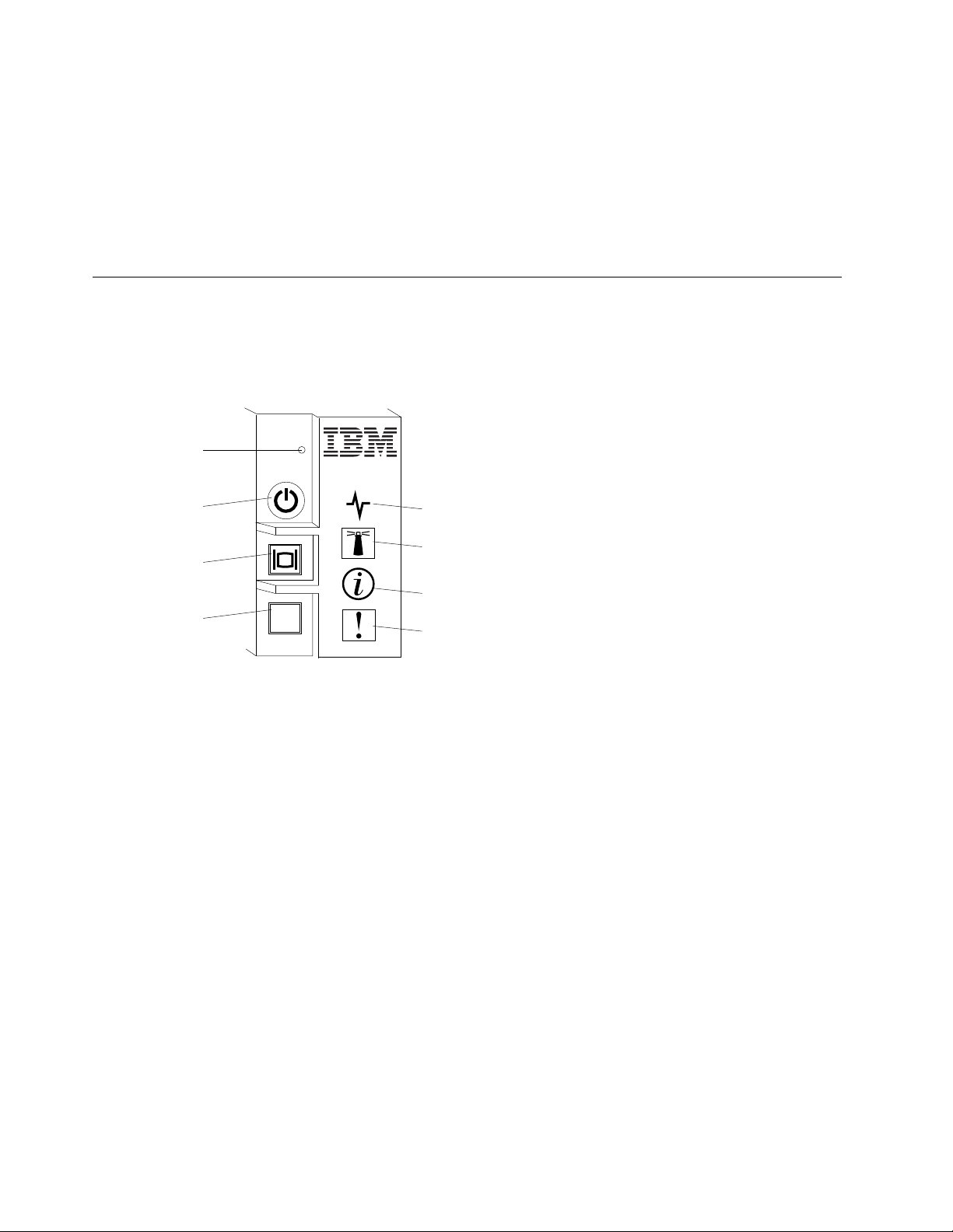
MT
Power button / LED
KVM select
button / LED
Media tray select
button / LED
Activity LED
Location LED
Information LED
Fault LED
NMI button
seconds to turn off the blade server.
Attention: Pressing the button for 4 seconds forces the operating system to shut down immediately. Data
loss is possible.
• You can turn off the blade server through the advanced management module web interface. For more
information about the advanced management module web interface, see the IBM BladeCenter Advanced
Management Module: User's Guide.
Blade server controls and LEDs
Use this information for details about the controls and LEDs on the blade server and IBM MAX5 expansion
blade.
The following illustration identifies the buttons and LEDs on the blade server control panel.
NMI button (recessed)
Power button/LED
16
The nonmaskable interrupt (NMI) dumps the partition. Use this recessed button only as directed by IBM
Support.
Note: You can also send an NMI event to the selected blade server remotely using the AMM. Refer to
the BladeCenter Advanced Management Module User's Guide for information pertaining to the proper
installation and configuration of Java, operating systems, and browsers that are supported for remote
access.
When the blade server has power, press this button to turn on or turn off the blade server.
Note: The power button works only if local power control is enabled for the blade server. Local power
control is enabled and disabled through the advanced management module web interface.
After the blade server is removed from the chassis, press this button to activate the system board LEDs
(light path diagnostics). See the Problem Determination and Service Guide for more information.
This button is also the power LED. This green LED indicates the power status of the blade server:
• Flashing rapidly: The LED flashes rapidly for one of the following reasons:
BladeCenter HX5 Blade ServerInstallation and User's Guide

– The blade server has been installed in a chassis. When you install the blade server, the LED flashes
rapidly for up to 90 seconds while the integrated management module (IMM) on the blade server is
initializing and synchronizing with the advanced management module.
– The blade server does not have power permissions assigned to it through the advanced
management module.
– The BladeCenter chassis does not have enough power to turn on the blade server.
– The IMM on the blade server is not communicating with the advanced management module.
• Flashing slowly: The blade server has power and is ready to be turned on.
• Lit continuously: The blade server has power and is turned on.
When the blade server is on, pressing this button causes an orderly shutdown of the blade server so that
it is safe to remove. This includes shutting down the operating system (if possible) and removing power
from the blade server.
Note: If you press the power button on the blade server that is part of a scalable blade complex running
as a single partition, both blade servers in the partition power on or shut down.
If an operating system is running, you might have to press the button for approximately 4 seconds to
initiate the shutdown.
Attention: Pressing the button for 4 seconds forces the operating system to shut down immediately.
Data loss is possible.
KVM select button/LED
Press this button to associate the shared BladeCenter chassis keyboard, video, and mouse (KVM) ports
with the blade server. The LED on this button flashes while the request is being processed and then is lit
when the ownership of the keyboard, video, and mouse has been transferred to the blade server. It can
take approximately 20 seconds to switch the keyboard, video, and mouse control to the blade server.
Using a keyboard that is directly attached to the advanced management module, you can press
keyboard keys in the following sequence to switch KVM control between blade servers instead of using
the KVM select button:
NumLock NumLock blade_server_number Enter
Where blade_server_number is the two-digit number of the blade server bay in which the blade
server is installed. A blade server that occupies more than one blade server bay is identified by the
lowest bay number that it occupies.
If there is no response when you press the KVM select button, you can use the advanced management
module web interface to determine whether local control has been disabled on the blade server. See the
IBM BladeCenter Advanced Management Module: User's Guide for more information.
Notes:
1. The operating system in the blade server must provide USB support for the blade server to
recognize and use the keyboard and mouse, even if the keyboard and mouse have PS/2-style
connectors.
2. If you install a supported MicrosoftWindows operating system on the blade server while it is not the
current owner of the keyboard, video, and mouse, a delay of up to 1 minute occurs the first time that
you switch the keyboard, video, and mouse to the blade server. All subsequent switching takes
place in the normal KVM switching time frame (up to 20 seconds).
Media tray select button/LED
Press this button to associate the shared BladeCenter chassis media tray (removable-media drives) with
the blade server. The LED on the button flashes while the request is being processed and then is lit when
Chapter 2. Power, controls, and indicators 17

the ownership of the media tray has been transferred to the blade server. It can take approximately 20
seconds for the operating system in the blade server to recognize the media tray.
If there is no response when you press the media-tray select button, you can use the advanced
management module web interface to determine whether local control has been disabled on the blade
server.
Note: The operating system in the blade server must provide USB support for the blade server to
recognize and use the removable-media drives.
Activity LED
When this green LED is lit (flashing), it indicates that there is activity on the network or external storage
device.
Location LED
The system administrator can remotely turn on this blue LED to aid in visually locating the blade server.
When this LED is lit, the location LED on the BladeCenter chassis is also lit. The location LED can be
turned on and off through the advanced management module web interface or through IBM Systems
Director. For more information about the advanced management module web interface, see the IBM
BladeCenter Advanced Management Module: User's Guide. For more information about IBM Systems
Director, see the documentation, which is available at http://publib.boulder.ibm.com/ infocenter/
director/v6r2x/index.jsp.
Information LED
When this amber LED is lit, it indicates that an Automatic BIOS recovery (ABR) has occurred. The blade
server starts up using the backup UEFI image. See the Problem Determination and Service Guide
The information LED can be turned off through the advanced management module CLI, SNMP, or web
interfaces or through IBM® Systems Director. For more information about the advanced management
module web interface, see the IBM BladeCenter Advanced Management Module: User's Guide. For
more information about IBM Systems Director, see the documentation, which is available at http://
publib.boulder.ibm.com/ infocenter/director/v6r2x/index.jsp.
Fault LED
When this amber LED is lit, it indicates that a system error has occurred in the blade server. In addition,
the fault LED on the chassis system LED panel is lit. See the Problem Determination and Service Guide
The fault LED turns off only after the error is corrected.
Note: When the fault LED turns off, you should also clear the IMM event log. Use the Setup utility to
clear the IMM event log.
IBM MAX5 LEDs
When there is a fault on the IBM MAX5 expansion blade, the front bezel of the IBM MAX5 expansion blade
will appear to have an orange glow. You can press the light path button on the system board of the IBM
MAX5 expansion blade to determine which LEDs are lit.
Note: If there is an orange glow, it will be referred to as MEU (Memory Expansion Unit) Fault in the system
event log.
The following LEDs are available on the IBM MAX5 expansion blade light path diagnostic panel:
See Light Path Below (LP1)
This amber LED indicates that there is a problem with the BladeCenter HX5 to which the IBM MAX5
expansion blade was attached. If this LED is lit, complete the following steps:
1. Remove the IBM MAX5 expansion blade (see “Removing an IBM MAX5” on page 29).
18
BladeCenter HX5 Blade ServerInstallation and User's Guide

2. Press the power button on the BladeCenter HX5 blade server to determine which LEDs are lit on the
blade server.
The See Light Path Below (LP1) LED is referred to as MEU Look Below in the system event log.
System Board (S BRD)
This amber LED indicates that there is a problem with the system board. If this amber LED is lit,
complete the following steps:
1. Install the IBM MAX5 (see “Installing an IBM MAX5” on page 63).
2. Install the BladeCenter HX5 in the chassis (see “Installing a blade server in a BladeCenter chassis”
on page 70).
3. Restart the blade server.
4. Check system-event and IMM/AMM logs related to memory and resolve those events (see the
Problem Determination and Service Guide).
5. If the problem remains, replace the system board on the IBM MAX5(see the Problem Determination
and Service Guide for instructions).
The System Board (S BRD) LED is referred to as MEU Error in the system-event log.
Light path power (LP2)
This amber LED indicates that one or more LEDs are lit on the IBM MAX5 system board. .
The Light path power (LP2) LED is referred to as MEU LED Power in the system event log.
See the Problem Determination and Service Guide
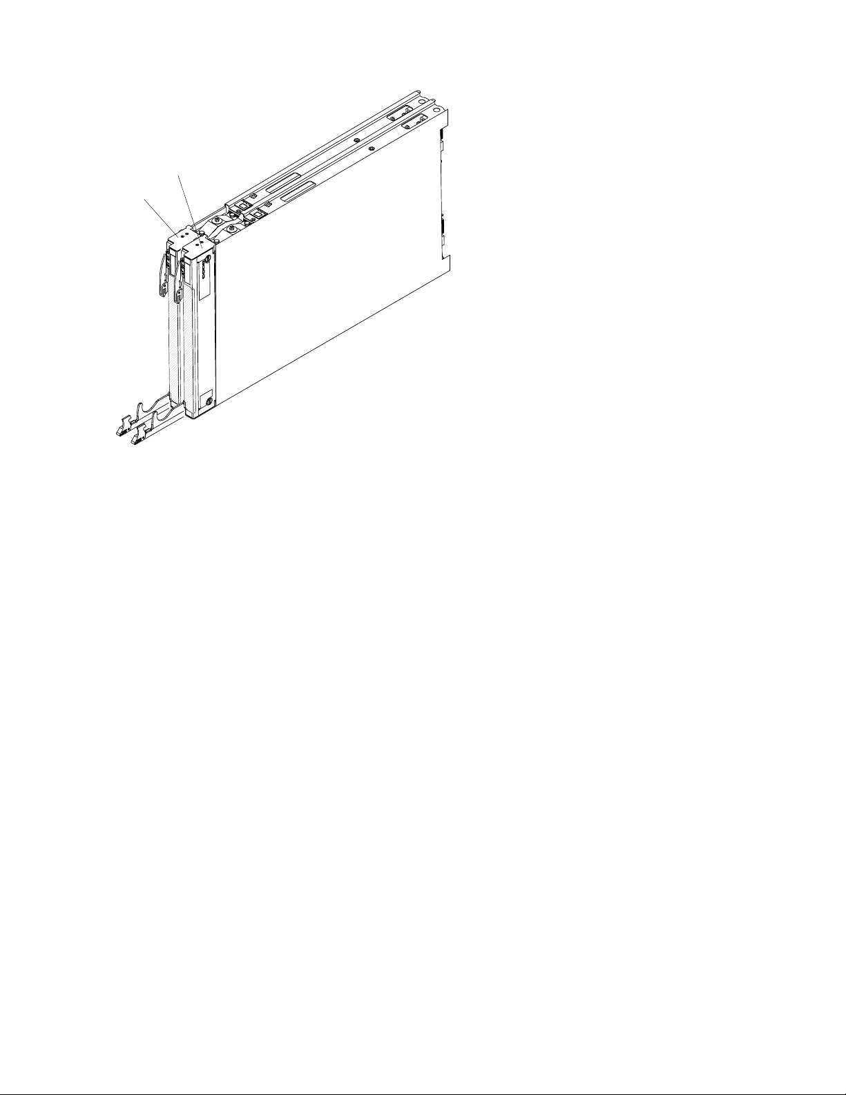
Scalability indicators
The BladeCenter HX5 blade server provides scalability indicators, which are viewable through the front bezel
of the blade server when it is installed in a BladeCenter chassis. The scalability indicators remain lit until the
blade server is started.
The BladeCenter HX5 blade server can be deployed as a stand-alone blade server. It can also be combined
with another BladeCenter HX5 blade server to form a scalable blade complex. When two BladeCenter HX5
blade servers are combined into a scalable blade complex, you can specify that they operate as a single
hardware partition or operate in stand-alone mode.
The scalability indicators show whether a BladeCenter HX5 blade server is a stand-alone blade server or a
node in a scalable blade complex operating as a single hardware partition.
When a BladeCenter HX5 blade server is a stand-alone blade server, the scalability indicators continually
move up and down the front of the bezel.
Chapter 2. Power, controls, and indicators 19
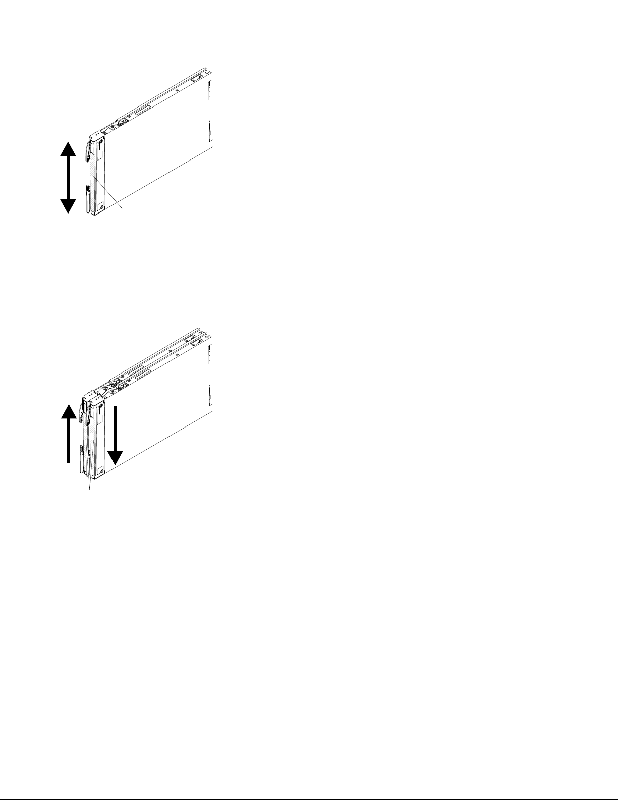
LEDs
When a BladeCenter HX5 blade server is part of the scalable blade complex operating in single partition
LEDs
mode, the scalability indicators move up the first blade server, cross over to the second blade server, and
then move down the second blade server.
Note: If you have set up a scalable blade complex in single partition mode but when you start the blade
servers, the scalability indicators for each blade server seem to be operating independently, there might be a
problem with the configuration of the scalable blade complex.
Blade server connectors - BladeCenter HX5
Use this information to locate blade server system board components and connectors for optional devices.
The following illustration shows the system board components, including connectors for user-installable
optional devices, in the blade server.
20
BladeCenter HX5 Blade ServerInstallation and User's Guide
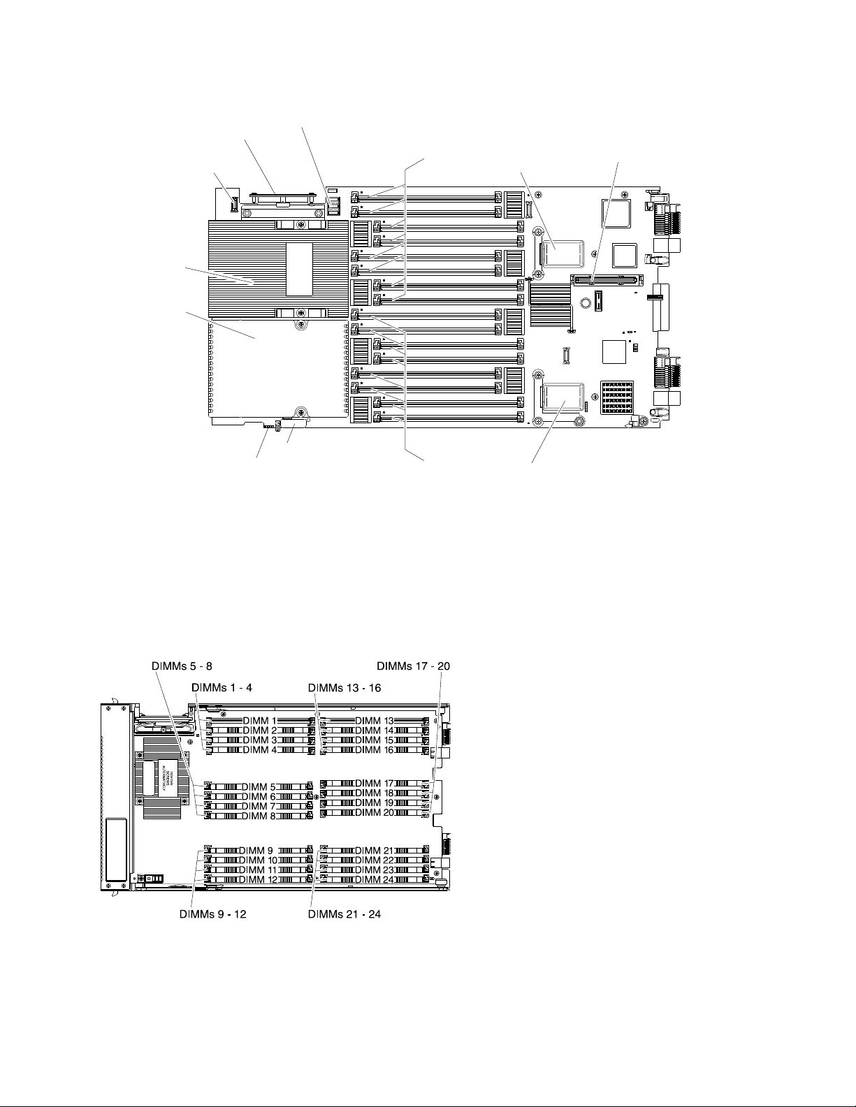
TIGHTEN
SCREWS
ALTERNATELY
Control panel
connector
Battery
Hypervisor
inteposer
connector
Microprocessor 2
I/O expansion
connector
(SSD)
Blade expansion
connector
I/O expansion
connector (CIOv)
Microprocessor 1
Scaling card
connector
Power
sharing
connector
DIMMs
1 - 8
DIMMs
9 - 16
Note: The optional SSD expansion card is installed in the I/O expansion connector (SSD).
Blade server connectors - IBM MAX5
Use this information to locate the IBM MAX5 expansion blade connectors.
The following illustration shows the system board components, including connectors for user-installable
optional devices, in the IBM MAX5 expansion blade.
Input/output connectors and devices
The input/output connectors that are available to the blade server are supplied by the BladeCenter chassis.
See the documentation that comes with the BladeCenter chassis for information about the input/output
connectors.
Chapter 2. Power, controls, and indicators 21

The blade server has two selection buttons on the control panel: the media tray select button and the
keyboard/video/mouse select button. See “Blade server controls and LEDs” on page 16 for information
about these buttons and their functions.
The Ethernet controllers on the blade server communicate with the network through the Ethernet-compatible
I/O modules in the BladeCenter chassis. Network signals to and from the blade server or any expansion
cards are automatically routed to a same-network-interface I/O module through circuitry in the BladeCenter
chassis.
22
BladeCenter HX5 Blade ServerInstallation and User's Guide
 Loading...