

Page 1

ThinkCentreM83,M93/p
UserGuide
MachineTypes:10A2,10A3,10A8,10A9,10AH,10AJ,10AM,and
10AN
Page 2

Note:Beforeusingthisinformationandtheproductitsupports,besuretoreadandunderstandthe
“Importantsafetyinformation”onpagev
andAppendixA“Notices”onpage149.
FirstEdition(June2013)
©CopyrightLenovo2013.
LIMITEDANDRESTRICTEDRIGHTSNOTICE:IfdataorsoftwareisdeliveredpursuantaGeneralServicesAdministration
“GSA”contract,use,reproduction,ordisclosureissubjecttorestrictionssetforthinContractNo.GS-35F-05925.
Page 3

Contents
Importantsafetyinformation......v
Serviceandupgrades.............v
Staticelectricityprevention...........v
Powercordsandpoweradapters........vi
Extensioncordsandrelateddevices.......vi
Plugsandoutlets..............vii
Externaldevices..............vii
Heatandproductventilation.........vii
Operatingenvironment...........viii
Modemsafetyinformation..........viii
Lasercompliancestatement..........ix
Powersupplystatement............ix
Cleaningandmaintenance...........ix
Chapter1.Productoverview......1
Features..................1
Specications................5
Lenovoprograms..............5
AccessingLenovoprogramsontheWindows
7operatingsystem............5
AccessingLenovoprogramsontheWindows
8operatingsystem............7
AnintroductiontoLenovoprograms.....7
Locations..................9
Locatingconnectors,controls,andindicators
onthefrontofyourcomputer.......10
Locatingconnectorsontherearofyour
computer...............10
Locatingcomponents..........14
Locatingpartsonthesystemboard....14
Locatinginternaldrives.........17
Machinetypeandmodellabel.......18
Chapter2.Usingyourcomputer...19
Frequentlyaskedquestions.........19
AccessingControlPanelontheWindows8
operatingsystem..............19
Usingthekeyboard.............20
UsingWindowsshortcutkeys.......20
UsingtheblueThinkVantagebutton....20
Usingangerprintreader........20
Usingthewheelmouse...........21
Adjustingaudio..............21
Aboutyourcomputeraudio........21
Settingthevolumefromthedesktop....21
SettingthevolumefromControlPanel...22
UsingCDsandDVDs............22
HandlingandstoringCDandDVDmedia..22
PlayingaCDorDVD..........23
RecordingaCDorDVD.........23
Chapter3.Y ouandyourcomputer..25
Accessibilityandcomfort..........25
Arrangingyourworkspace........25
Comfort...............25
Glareandlighting............26
Aircirculation.............26
Electricaloutletsandcablelengths.....26
Registeringyourcomputer..........27
Movingyourcomputertoanothercountryor
region..................27
Replacementpowercords........27
Chapter4.Security..........29
Securityfeatures..............29
Lockingthecomputercover.........29
AttachingaKensington-stylecablelock.....31
Attachingacablelock............32
Usingpasswords..............32
BIOSpasswords............32
Windowspasswords..........33
Conguringthengerprintreader.......33
Usingandunderstandingrewalls.......33
Protectingdataagainstviruses........33
Chapter5.Installingorreplacing
hardware...............35
Handlingstatic-sensitivedevices.......35
Installingorreplacinghardware........35
Installingexternaloptions........35
Removingthecomputercover.......36
Removingandreinstallingthefrontbezel..36
Accessingthesystemboardcomponentsand
drives................38
InstallingorreplacingaPCIcard......38
Installingorreplacingamemorymodule...40
Replacingtheopticaldrive........42
Installingorreplacingthecardreader
assembly...............45
InstallingorreplacingthefrontUSB
assembly...............50
Replacingthebattery..........55
InstallingorreplacingthemSAT Asolid-state
drive.................56
Replacingthepowersupplyassembly...62
Replacingtheheatsinkandfanassembly..65
©CopyrightLenovo2013
i
Page 4

Replacingthemicroprocessor.......68
Replacingthecoverpresenceswitch....70
Replacingtheprimaryharddiskdrive....72
Installingorreplacingthesecondaryharddisk
drive.................74
Installingthesolid-statedrive.......81
Replacingthefrontfanassembly.....83
ReplacingthefrontaudioandUSB
assembly...............85
Replacingtheinternalspeaker.......87
Replacingthethermalsensor.......89
ReplacingtheWi-Fiunits.........91
InstallingorremovingtherearWi-Fiantenna.96
InstallingorremovingthefrontWi-Fi
antenna...............99
Replacingthekeyboardormouse.....102
Completingthepartsreplacement.....103
Chapter6.Recoveryinformation..107
RecoveryinformationfortheWindows7operating
system..................107
Creatingandusingrecoverymedia.....107
Performingbackupandrecovery
operations..............108
UsingtheRescueandRecovery
workspace..............109
Creatingandusingarescuemedium....110
Reinstallingpreinstalledapplicationsand
devicedrivers.............111
Reinstallingsoftwareprograms......112
Reinstallingdevicedrivers........112
Solvingrecoveryproblems........112
RecoveryinformationfortheWindows8operating
system..................113
Chapter7.UsingtheSetupUtility
program...............115
StartingtheSetupUtilityprogram.......115
Viewingandchangingsettings........115
Usingpasswords..............115
Passwordconsiderations.........116
Power-OnPassword..........116
AdministratorPassword.........116
HardDiskPassword...........116
Setting,changing,anddeletingapassword..116
Erasinglostorforgottenpasswords(clearing
CMOS)................117
Enablingordisablingadevice........117
Selectingastartupdevice..........118
Selectingatemporarystartupdevice....118
Selectingorchangingthestartupdevice
sequence...............118
EnablingErPcompliancemode........118
ICEperformancemode...........119
ICEthermalalert..............119
ExitingtheSetupUtilityprogram.......120
Chapter8.Updatingsystem
programs..............121
Usingsystemprograms...........121
Updating(ashing)theBIOSfromadisc....121
Updating(ashing)theBIOSfromyouroperating
system..................122
RecoveringfromaPOST/BIOSupdatefailure..122
Chapter9.Preventingproblems..123
Keepingyourcomputercurrent........123
Gettingthelatestdevicedriversforyour
computer...............123
Updatingyouroperatingsystem......123
UsingSystemUpdate..........124
Cleaningandmaintenance..........124
Basics................124
Cleaningyourcomputer.........125
Goodmaintenancepractices.......126
Movingyourcomputer...........126
Chapter10.Troubleshootingand
diagnostics.............127
Basictroubleshooting............127
Troubleshootingprocedure..........128
Troubleshooting..............128
Audioproblems............129
CDproblems.............130
DVDproblems.............131
Intermittentproblems..........133
Keyboard,mouse,orpointingdevice
problems...............133
Monitorproblems............135
Networkingproblems..........136
Optionproblems............139
Performanceandlockupproblems.....140
Printerproblems............141
Serialportproblems...........142
Softwareproblems...........142
USBproblems.............143
LenovoSolutionCenter...........144
Chapter11.Gettinginformation,help,
andservice.............145
Informationresources............145
LenovoThinkVantageT ools........145
LenovoWelcome............145
HelpandSupport............145
SafetyandWarranty...........145
iiThinkCentreM83,M93/pUserGuide
Page 5

LenovoWebsite............145
LenovoSupportWebsite.........146
Helpandservice..............146
Usingthedocumentationanddiagnostic
program...............146
Callingforservice............146
Usingotherservices..........147
Purchasingadditionalservices......147
AppendixA.Notices.........149
Trademarks................150
AppendixB.Regulatory
information.............151
Exportclassicationnotice..........151
Electronicemissionsnotices.........151
FederalCommunicationsCommission
DeclarationofConformity........151
Eurasiancompliancemark..........153
Additionalregulatoryinformation.......153
AppendixC.WEEEandrecycling
information.............155
ImportantWEEEinformation.........155
RecyclinginformationforJapan........155
RecyclinginformationforBrazil........156
BatteryrecyclinginformationforTaiwan.....156
BatteryrecyclinginformationfortheEuropean
Union..................156
AppendixD.RestrictionofHazardous
SubstancesDirective(RoHS)....159
EuropeanUnionRoHS...........159
ChinaRoHS................159
TurkishRoHS...............159
UkraineRoHS...............160
IndiaRoHS................160
AppendixE.ENERGYSTARmodel
information.............161
Index.................163
©CopyrightLenovo2013
iii
Page 6

ivThinkCentreM83,M93/pUserGuide
Page 7

Importantsafetyinformation
CAUTION:
Beforeusingthismanual,besuretoreadandunderstandalltherelatedsafetyinformationforthis
product.RefertotheinformationinthissectionandthesafetyinformationintheSafety,Warranty,and
SetupGuidethatyoureceivedwiththisproduct.Readingandunderstandingthissafetyinformation
reducestheriskofpersonalinjuryanddamagetoyourproduct.
IfyounolongerhaveacopyoftheSafety,Warranty,andSetupGuide,youcanobtainaPortableDocument
Format(PDF)versionfromtheLenovo
®
SupportWebsiteathttp://www.lenovo.com/support.TheLenovo
SupportWebsitealsoprovidestheSafety,Warranty,andSetupGuideandthisUserGuideinadditional
languages.
Serviceandupgrades
DonotattempttoserviceaproductyourselfunlessinstructedtodosobytheCustomerSupportCenteror
yourdocumentation.OnlyuseaServiceProviderwhoisapprovedtorepairyourparticularproduct.
Note:Somecomputerpartscanbeupgradedorreplacedbythecustomer.Upgradestypicallyare
referredtoasoptions.ReplacementpartsapprovedforcustomerinstallationarereferredtoasCustomer
ReplaceableUnits,orCRUs.Lenovoprovidesdocumentationwithinstructionswhenitisappropriatefor
customerstoinstalloptionsorreplaceCRUs.Y oumustcloselyfollowallinstructionswheninstallingor
replacingparts.TheOffstateofapowerindicatordoesnotnecessarilymeanthatvoltagelevelsinsidea
productarezero.Beforeyouremovethecoversfromaproductequippedwithapowercord,alwaysmake
surethatthepoweristurnedoffandthattheproductisunpluggedfromanypowersource.Formore
informationonCRUs,refertoChapter5“Installingorreplacinghardware”onpage35
.Ifyouhaveany
questionsorconcerns,contacttheCustomerSupportCenter.
Althoughtherearenomovingpartsinyourcomputerafterthepowercordhasbeendisconnected,the
followingwarningsarerequiredforyoursafety.
CAUTION:
Hazardousmovingparts.Keepngersandotherbodypartsaway.
CAUTION:
BeforereplacinganyCRUs,turnoffthecomputerandwaitthreetoveminutestoletthecomputer
coolbeforeopeningthecover.
Staticelectricityprevention
Staticelectricity,althoughharmlesstoyou,canseriouslydamagecomputercomponentsandoptions.
Improperhandlingofstatic-sensitivepartscancausedamagetothepart.Whenyouunpackanoption
©CopyrightLenovo2013
v
Page 8

orCRU,donotopenthestatic-protectivepackagecontainingthepartuntiltheinstructionsdirectyou
toinstallit.
WhenyouhandleoptionsorCRUs,orperformanyworkinsidethecomputer,takethefollowingprecautions
toavoidstatic-electricitydamage:
•Limityourmovement.Movementcancausestaticelectricitytobuilduparoundyou.
•Alwayshandlecomponentscarefully.Handleadapters,memorymodules,andothercircuitboardsbythe
edges.Nevertouchexposedcircuitry.
•Preventothersfromtouchingcomponents.
•Whenyouinstallastatic-sensitiveoptionorCRU,touchthestatic-protectivepackagecontainingthe
parttoametalexpansion-slotcoverorotherunpaintedmetalsurfaceonthecomputerforatleasttwo
seconds.Thisreducesstaticelectricityinthepackageandyourbody.
•Whenpossible,removethestatic-sensitivepartfromthestatic-protectivepackagingandinstallthepart
withoutsettingitdown.Whenthisisnotpossible,placethestatic-protectivepackagingonasmooth,
levelsurfaceandplacethepartonit.
•Donotplacethepartonthecomputercoverorothermetalsurface.
Powercordsandpoweradapters
Useonlythepowercordsandpoweradapterssuppliedbytheproductmanufacturer.
Thepowercordsshallbesafetyapproved.ForGermany,itshallbeH05VV-F,3G,0.75mm
2
,orbetter.For
othercountries,thesuitabletypesshallbeusedaccordingly.
Neverwrapapowercordaroundapoweradapterorotherobject.Doingsocanstressthecordinwaysthat
cancausethecordtofray,crack,orcrimp.Thiscanpresentasafetyhazard.
Alwaysroutepowercordssothattheywillnotbewalkedon,trippedover,orpinchedbyobjects.
Protectpowercordandpoweradaptersfromliquids.Forinstance,donotleaveyourpowercordorpower
adapternearsinks,tubs,toilets,oronoorsthatarecleanedwithliquidcleansers.Liquidscancausea
shortcircuit,particularlyifthepowercordorpoweradapterhasbeenstressedbymisuse.Liquidsalsocan
causegradualcorrosionofpowercordterminalsand/ortheconnectorterminalsonapoweradapter,
whichcaneventuallyresultinoverheating.
Ensurethatallpowercordconnectorsaresecurelyandcompletelypluggedintoreceptacles.
Donotuseanypoweradapterthatshowscorrosionattheacinputpinsorshowssignsofoverheating(such
asdeformedplastic)attheacinputoranywhereonthepoweradapter.
Donotuseanypowercordswheretheelectricalcontactsoneitherendshowsignsofcorrosionor
overheatingorwherethepowercordappearstohavebeendamagedinanyway.
Extensioncordsandrelateddevices
Ensurethatextensioncords,surgeprotectors,uninterruptiblepowersupplies,andpowerstripsthatyouuse
areratedtohandletheelectricalrequirementsoftheproduct.Neveroverloadthesedevices.Ifpowerstrips
areused,theloadshouldnotexceedthepowerstripinputrating.Consultanelectricianformoreinformation
ifyouhavequestionsaboutpowerloads,powerrequirements,andinputratings.
viThinkCentreM83,M93/pUserGuide
Page 9

Plugsandoutlets
Ifareceptacle(poweroutlet)thatyouintendtousewithyourcomputerequipmentappearstobedamaged
orcorroded,donotusetheoutletuntilitisreplacedbyaqualiedelectrician.
Donotbendormodifytheplug.Iftheplugisdamaged,contactthemanufacturertoobtainareplacement.
Donotshareanelectricaloutletwithotherhomeorcommercialappliancesthatdrawlargeamountsof
electricity;otherwise,unstablevoltagemightdamageyourcomputer,data,orattacheddevices.
Someproductsareequippedwithathree-prongedplug.Thisplugtsonlyintoagroundedelectricaloutlet.
Thisisasafetyfeature.Donotdefeatthissafetyfeaturebytryingtoinsertitintoanon-groundedoutlet.If
youcannotinserttheplugintotheoutlet,contactanelectricianforanapprovedoutletadapterortoreplace
theoutletwithonethatenablesthissafetyfeature.Neveroverloadanelectricaloutlet.Theoverallsystem
loadshouldnotexceed80percentofthebranchcircuitrating.Consultanelectricianformoreinformation
ifyouhavequestionsaboutpowerloadsandbranchcircuitratings.
Besurethatthepoweroutletyouareusingisproperlywired,easilyaccessible,andlocatedclosetothe
equipment.Donotfullyextendpowercordsinawaythatwillstressthecords.
Besurethatthepoweroutletprovidesthecorrectvoltageandcurrentfortheproductyouareinstalling.
Carefullyconnectanddisconnecttheequipmentfromtheelectricaloutlet.
Externaldevices
DonotconnectordisconnectanyexternaldevicecablesotherthanUniversalSerialBus(USB)and1394
cableswhilethecomputerpowerison;otherwise,youmightdamageyourcomputer.Toavoidpossible
damagetoattacheddevices,waitatleastvesecondsafterthecomputerisshutdowntodisconnect
externaldevices.
Heatandproductventilation
Computers,poweradapters,andmanyaccessoriescangenerateheatwhenturnedonandwhenbatteries
arecharging.Alwaysfollowthesebasicprecautions:
•Donotleaveyourcomputer,poweradapter,oraccessoriesincontactwithyourlaporanypartofyour
bodyforanextendedperiodwhentheproductsarefunctioningorwhenthebatteryischarging.Your
computer,poweradapter,andmanyaccessoriesproducesomeheatduringnormaloperation.Extended
contactwiththebodycouldcausediscomfortor,potentially,askinburn.
•Donotchargethebatteryoroperateyourcomputer,poweradapter,oraccessoriesnearammable
materialsorinexplosiveenvironments.
•Ventilationslots,fans,andheatsinksareprovidedwiththeproductforsafety,comfort,andreliable
operation.Thesefeaturesmightinadvertentlybecomeblockedbyplacingtheproductonabed,sofa,
carpet,orotherexiblesurface.Neverblock,cover,ordisablethesefeatures.
Inspectyourdesktopcomputerfordustaccumulationatleastonceeverythreemonths.Beforeinspecting
yourcomputer,turnoffthepowerandunplugthecomputer'spowercordfromtheelectricaloutlet;then
removeanydustfromventsandperforationsinthebezel.Ifyounoticeexternaldustaccumulation,then
examineandremovedustfromtheinsideofthecomputerincludingheatsinkinletns,powersupplyvents,
andfans.Alwaysturnoffandunplugthecomputerbeforeopeningthecover.Ifpossible,avoidoperating
yourcomputerwithintwofeetofhigh-trafcareas.Ifyoumustoperateyourcomputerinornearahigh-trafc
area,inspectand,ifnecessary,cleanyourcomputermorefrequently.
©CopyrightLenovo2013
vii
Page 10

Foryoursafetyandtomaintainoptimumcomputerperformance,alwaysfollowthesebasicprecautions
withyourdesktopcomputer:
•Keepthecoverclosedwheneverthecomputerispluggedin.
•Regularlyinspecttheoutsideofthecomputerfordustaccumulation.
•Removedustfromventsandanyperforationsinthebezel.Morefrequentcleaningsmightberequiredfor
computersindustyorhigh-trafcareas.
•Donotrestrictorblockanyventilationopenings.
•Donotstoreoroperateyourcomputerinsidefurniture,asthismightincreasetheriskofoverheating.
•Airowtemperaturesintothecomputershouldnotexceed35°C(95°F).
•Donotinstallairltrationdevices.Theymayinterferewithpropercooling.
Operatingenvironment
Theoptimalenvironmentinwhichtouseyourcomputeris10°C-35°C(50°F-95°F)withhumidityranging
between35%and80%.Ifyourcomputerisstoredortransportedintemperatureslessthan10°C(50°F),
allowthecoldcomputertoriseslowlytoanoptimaloperatingtemperatureof10°C-35°C(50°F-95°F)before
use.Thisprocesscouldtaketwohoursinextremeconditions.Failuretoallowyourcomputertorisetoan
optimaloperatingtemperaturebeforeusecouldresultinirreparabledamagetoyourcomputer.
Ifpossible,placeyourcomputerinawell-ventilatedanddryareawithoutdirectexposuretosunshine.
Keepelectricalappliancessuchasanelectricfan,radio,high-poweredspeakers,airconditioner,and
microwaveovenawayfromyourcomputerbecausethestrongmagneticeldsgeneratedbythese
appliancescandamagethemonitoranddataontheharddiskdrive.
Donotplaceanybeveragesontopoforbesidethecomputerorotherattacheddevices.Ifliquidisspilledon
orinthecomputeroranattacheddevice,ashortcircuitorotherdamagemightoccur.
Donoteatorsmokeoveryourkeyboard.Particlesthatfallintoyourkeyboardcancausedamage.
Modemsafetyinformation
CAUTION:
Toreducetheriskofre,useonlyNo.26AWGorlarger(forexample,No.24AWG)telecommunication
linecordlistedbyUnderwritersLaboratories(UL)orcertiedbytheCanadianStandardsAssociation
(CSA).
Toreducetheriskofre,electricalshock,orinjurywhenusingtelephoneequipment,alwaysfollowbasic
safetyprecautions,suchas:
•Neverinstalltelephonewiringduringalightningstorm.
•Neverinstalltelephonejacksinwetlocationsunlessthejackisspecicallydesignedforwetlocations.
•Nevertouchuninsulatedtelephonewiresorterminalsunlessthetelephonelinehasbeendisconnectedat
thenetworkinterface.
•Usecautionwheninstallingormodifyingtelephonelines.
•Avoidusingatelephone(otherthanacordlesstype)duringanelectricalstorm.Theremaybearemote
riskofelectricshockfromlightning.
•Donotusethetelephonetoreportagasleakinthevicinityoftheleak.
viiiThinkCentreM83,M93/pUserGuide
Page 11

Lasercompliancestatement
CAUTION:
Whenlaserproducts(suchasCD-ROMs,DVDdrives,beropticdevices,ortransmitters)are
installed,notethefollowing:
•Donotremovethecovers.Removingthecoversofthelaserproductcouldresultinexposureto
hazardouslaserradiation.Therearenoserviceablepartsinsidethedevice.
•Useofcontrolsoradjustmentsorperformanceofproceduresotherthanthosespeciedherein
mightresultinhazardousradiationexposure.
DANGER
SomelaserproductscontainanembeddedClass3AorClass3Blaserdiode.Notethefollowing:
Laserradiationwhenopen.Donotstareintothebeam,donotviewdirectlywithoptical
instruments,andavoiddirectexposuretothebeam.
Powersupplystatement
Neverremovethecoveronapowersupplyoranypartthathasthefollowinglabelattached.
Hazardousvoltage,current,andenergylevelsarepresentinsideanycomponentthathasthislabelattached.
Therearenoserviceablepartsinsidethesecomponents.Ifyoususpectaproblemwithoneoftheseparts,
contactaservicetechnician.
Cleaningandmaintenance
Keepyourcomputerandworkspaceclean.Shutdownthecomputerandthendisconnectthepower
cordbeforecleaningthecomputer.Donotsprayanyliquiddetergentdirectlyonthecomputeroruse
anydetergentcontainingammablematerialtocleanthecomputer.Spraythedetergentonasoftcloth
andthenwipethecomputersurfaces.
©CopyrightLenovo2013
ix
Page 12

xThinkCentreM83,M93/pUserGuide
Page 13

Chapter1.Productoverview
Thischapterprovidesinformationaboutthecomputerfeatures,specications,softwareprogramsprovided
byLenovo,andlocationsofconnectors,components,partsonthesystemboard,andinternaldrives.
Features
Thissectionintroducesthecomputerfeatures.Theinformationcoversavarietyofmodels.
Toviewtheinformationaboutyourspecicmodel,dooneofthefollowing:
•GointotheSetupUtilityprogrambyfollowingtheinstructionsinChapter7“UsingtheSetupUtility
program”onpage115.Then,selectMain➙SystemSummarytoviewtheinformation.
•OntheMicrosoft
®
Windows
®
7operationsystem,clickStart,right-clickComputer,andselectProperties
toviewtheinformation.
•OntheMicrosoftWindows8operatingsystem,moveyourcursortothetop-rightorbottom-rightcorner
ofthescreentodisplaythecharms.ThenclickSettings➙PCinfotoviewtheinformation.
Microprocessor
Yourcomputercomeswithoneofthefollowingmicroprocessors(internalcachesizevariesbymodeltype):
•Intel
®
Core™i5microprocessor
•IntelCorei7microprocessor
•IntelCeleron
®
microprocessor
•IntelPentium
®
microprocessor
Memory
Yourcomputersupportsuptofourdoubledatarate3unbuffereddualinlinememorymodules(DDR3
UDIMMs).
Internaldrives
•mSATAsolid-statedrive(optional)
•Opticaldrive:DVD-ROMorDVD-Rambo(optional)
•SerialAdvancedT echnologyAttachment(SATA)harddiskdrive
•SATAsolid-statedrive(optional)
Note:YourcomputersupportseSATAandSATA3.0devices.Formoreinformation,see“Locatingparts
onthesystemboard”onpage14
.
Videosubsystem
•IntegratedgraphicsforaVideoGraphicsArray(VGA)connectorandtwoDisplayPortconnectors
•PeripheralComponentInterconnect(PCI)Expressx16graphicscardslotonthesystemboardfora
discretegraphicscard
Audiosubsystem
•Integratedhigh-denition(HD)audio
©CopyrightLenovo2013
1
Page 14

•Audioline-inconnector,audioline-outconnector,andmicrophoneconnectorontherearpanel
•Microphoneconnectorandheadphoneconnectoronthefrontpanel
•Internalspeaker(availableinsomemodels)
Connectivity
•100/1000MbpsintegratedEthernetcontroller
•PCIFaxmodem(availableinsomemodels)
Systemmanagementfeatures
•Abilitytostorepower-onself-test(POST)hardwaretestresults
•DesktopManagementInterface(DMI)
DesktopManagementInterfaceprovidesacommonpathforuserstoaccessinformationaboutall
aspectsofacomputer,includingprocessortype,installationdate,attachedprintersandotherperipherals,
powersources,andmaintenancehistory.
•ErPcompliancemode
Theenergy-relatedproductsdirective(ErP)compliancemodereducestheconsumptionofelectricity
whenyourcomputerisinstandbyoroffmode.Formoreinformation,see“EnablingErPcompliance
mode”onpage118
.
•IntelStandardManageability
IntelStandardManageabilityishardwareandrmwaretechnologythatbuildscertainfunctionality
intocomputersinordertomakethemeasierandlessexpensiveforbusinessestomonitor,maintain,
update,upgrade,andrepair.
•IntelActiveManagementTechnology(AMT)(availableonsomemodels)
IntelActiveManagementTechnologyishardwareandrmwaretechnologythatbuildscertainfunctionality
intocomputersinordertomakethemeasierandlessexpensiveforbusinessestomonitor,maintain,
update,upgrade,andrepair.
•IntelMatrixStorageManager
IntelMatrixStorageManagerisadevicedriverthatprovidessupportforSATARAID5arraysandSATA
RAID10arraysonspecicIntelchipsetsystemboardstoenhanceharddiskperformance.
•PrebootExecutionEnvironment(PXE)
ThePrebootExecutionEnvironmentisanenvironmenttostartcomputersusinganetworkinterface
independentofdatastoragedevices(suchastheharddiskdrive)orinstalledoperatingsystems.
•IntelligentCoolingEngine(ICE)
TheIntelligentCoolingEngineisasystemthermalmanagementsolutionthatenablesyourcomputer
torunwithbetterthermalandacousticperformance.TheICEfunctionalsomonitorsthethermal
performanceofyourcomputertoidentifythermalproblems.Formoreinformation,see“ICEperformance
mode”onpage119
and“ICEthermalalert”onpage119.
•SystemManagement(SM)BasicInput/OutputSystem(BIOS)andSMsoftware
TheSMBIOSspecicationdenesdatastructuresandaccessmethodsinaBIOSthatallowsauseror
applicationtostoreandretrieveinformationspecicaboutthecomputerinquestion.
•WakeonLAN
WakeonLANisanEthernetcomputernetworkingstandardthatallowsacomputertobeturnedon
orwokenupbyanetworkmessage.Themessageisusuallysentbyaprogramrunningonanother
computeronthesamelocalareanetwork.
2ThinkCentreM83,M93/pUserGuide
Page 15

•WakeonRing
WakeonRing,sometimesreferredtoasWakeonModem,isaspecicationthatallowssupported
computersanddevicestoresumefromsleeporhibernationmode.
•WindowsManagementInstrumentation(WMI)
WindowsManagementInstrumentationisasetofextensionstotheWindowsDriverModel.Itprovidesan
operatingsysteminterfacethroughwhichinstrumentedcomponentsprovideinformationandnotication.
Input/Output(I/O)features
•9-pinserialport(onestandardandoneoptional)
•EightUniversalSerialBus(USB)connectors(twoonthefrontpanelandsixontherearpanel)
•OneEthernetconnector
•OnePersonalSystem/2(PS/2)keyboardconnector(optional)
•OnePS/2mouseconnector(optional)
•OneVGAmonitorconnector
•Threeaudioconnectorsontherearpanel(audioline-inconnector,audioline-outconnector,and
microphoneconnector)
•Twoaudioconnectorsonthefrontpanel(microphoneconnectorandheadphoneconnector)
•TwoDisplayPortconnectors
Formoreinformation,see“Locatingconnectors,controls,andindicatorsonthefrontofyourcomputer”on
page10
and“Locatingconnectorsontherearofyourcomputer”onpage10.
Expansion
•Onedrivebayassembly
•OnePCIcardslot(availableinThinkCentre®M93/pcomputers)
•OnePCIExpressx1cardslot
•OnePCIExpressx16graphicscardslot
•OnePCIExpresscardslot(physicallinkwidthx16;negotiablelinkwidthx4,x1)
•“Locatingpartsonthesystemboard”onpage14.
Formoreinformation,see“Locatinginternaldrives”onpage17and“Locatingpartsonthesystemboard”
onpage14.
Powersupply
Yourcomputercomeswitha240-wattautomaticvoltage-sensingpowersupply.
Securityfeatures
•Abilitytoenableordisableadevice
•AbilitytoenableordisableUSBconnectorsindividually
•ComputraceAgentsoftwareembeddedinrmware
•Coverpresenceswitch(alsocalledintrusionswitch)
•Keyboardwithngerprintreader(shippedwithsomemodels)
•Power-onpassword(POP),administratorpassword,andharddiskdrivepasswordtodeterunauthorized
useofyourcomputer
•SupportforaKensington-stylecablelock
Chapter1.Productoverview3
Page 16

•Supportforapadlock
•Startupsequencecontrol
•Startupwithoutkeyboardormouse
•TrustedPlatformModule(TPM)
Formoreinformation,seeChapter4“Security”onpage29.
Preinstalledsoftwareprograms
Yourcomputerispreinstalledwithsoftwareprogramstohelpyouworkmoreeasilyandsecurely.Formore
information,see“Lenovoprograms”onpage5
.
Preinstalledoperatingsystem
Yourcomputerispreinstalledwithoneofthefollowingoperatingsystems:
•Windows7operatingsystem
•Windows8operatingsystem
Operatingsystem(s),certiedortestedforcompatibility
1
(variesbymodeltype)
•Linux
®
1.Theoperatingsystem(s)listedherearebeingcertiedortestedforcompatibilityatthetimethispublicationgoesto
press.AdditionaloperatingsystemsmightbeidentiedbyLenovoascompatiblewithyourcomputerfollowingthe
publicationofthismanual.Thislistissubjecttochange.Todetermineifanoperatingsystemhasbeencertiedor
testedforcompatibility,checktheWebsiteoftheoperatingsystemvendor.
4ThinkCentreM83,M93/pUserGuide
Page 17

Specications
Thissectionliststhephysicalspecicationsforyourcomputer.
Dimensions
Width:102mm(4.02inches)
Height:338mm(13.31inches)
Depth:375mm(14.76inches)
Weight
Maximumcongurationasshipped:7.8kg(17.20lb)
Environment
•Airtemperature:
Operating:10°Cto35°C(50°Fto95°F)
Storageinoriginalshippingpackage:-40°Cto60°C(-40°Fto140°F)
Storagewithoutpackage:-10°Cto60°C(14°Fto140°F)
•Humidity:
Operating:20%to80%(non-condensing)
Storage:20%to90%(non-condensing)
•Altitude:
Operating:-15.2to3048m(-50to10000ft)
Storage:-15.2to10668m(-50to35000ft)
Electricalinput
•Inputvoltage:
–Lowrange:
Minimum:100Vac
Maximum:127Vac
Inputfrequencyrange:50/60Hz
–Highrange:
Minimum:200Vac
Maximum:240Vac
Inputfrequencyrange:50/60Hz
Lenovoprograms
YourcomputercomeswithLenovoprogramstohelpyouworkmoreeasilyandsecurely.Dependingon
theWindowsoperatingsystempreinstalled,theprogramsmightvary.
AccessingLenovoprogramsontheWindows7operatingsystem
OntheWindows7operatingsystem,youcanaccessLenovoprogramsfromeithertheLenovo
ThinkVantage
®
ToolsprogramorfromControlPanel.
AccessingLenovoprogramsfromtheLenovoThinkVantageT oolsprogram
ToaccessLenovoprogramsfromtheLenovoThinkVantageToolsprogram,clickStart➙AllPrograms➙
LenovoThinkVantageTools.Thendouble-clickaprogramicontoaccesstheprogram.
Chapter1.Productoverview5
Page 18
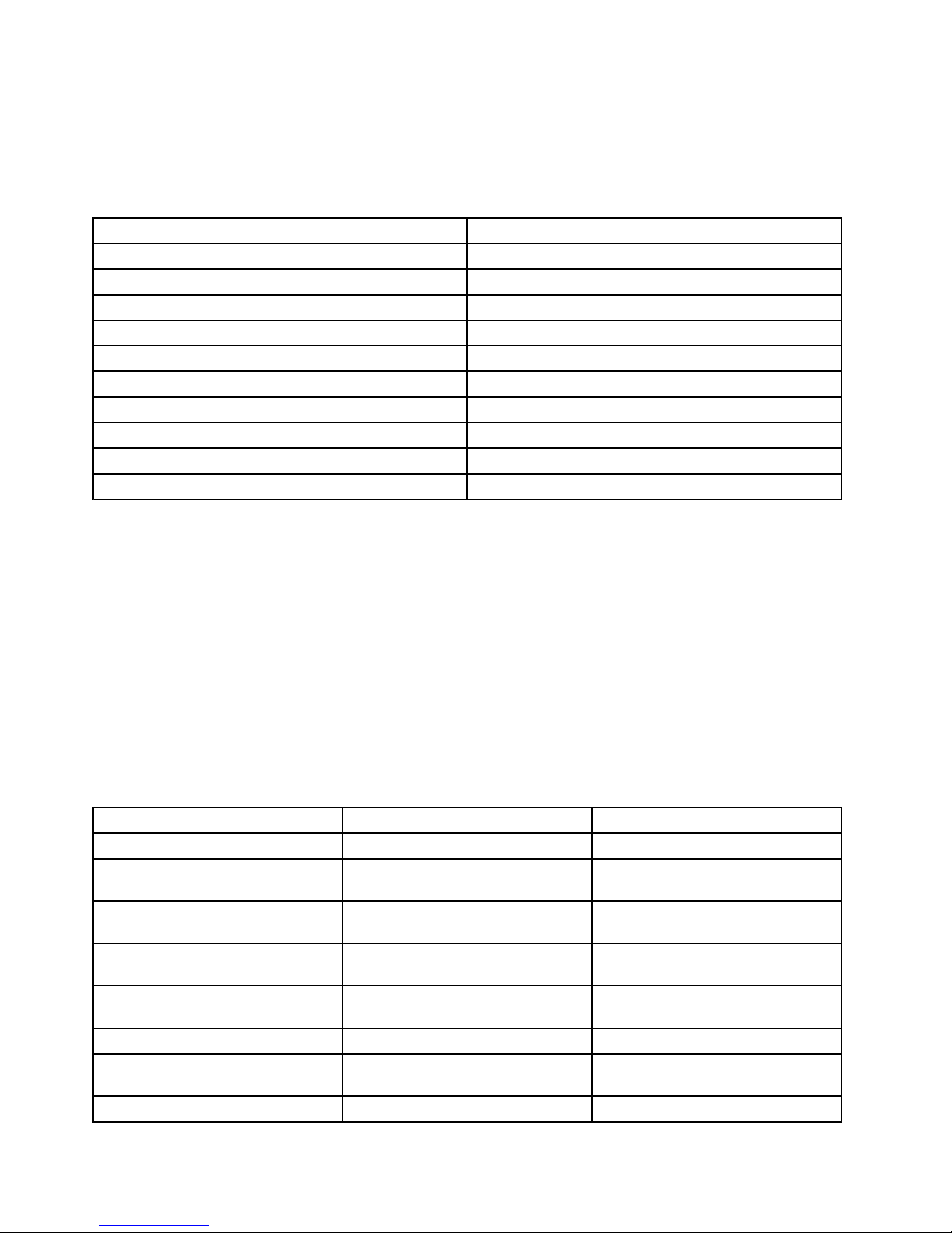
Note:IfaprogramiconintheLenovoThinkVantageToolsprogramnavigationwindowisdimmed,it
indicatesthatyouneedtoinstalltheprogrammanually.Toinstalltheprogrammanually,double-clickthe
programicon.Then,followtheinstructionsonthescreen.Whentheinstallationprocesscompletes,the
programiconwillbeactivated.
Table1.ProgramsintheLenovoThinkVantageToolsprogram
ProgramIconname
CommunicationsUtilityWebConferencing
FingerprintSoftware
FingerprintReader
LenovoSolutionCenterSystemHealthandDiagnostics
PasswordManagerPasswordVault
PowerManager
PowerControls
RecoveryMediaFactoryRecoveryDisks
RescueandRecovery
®
EnhancedBackupandRestore
SimpleTapSimpleTap
SystemUpdate
UpdateandDrivers
ViewManagementUtility
ScreenLayout
Note:Dependingonyourcomputermodel,someoftheprogramsmightnotbeavailable.
AccessingLenovoprogramsfromControlPanel
ToaccessLenovoprogramsfromControlPanel,clickStart➙ControlPanel.Thendependingonthe
programyouwanttoaccess,clickthecorrespondingsectionandthenclickthecorrespondinggreentext.
Note:IfyoudonotndtheprogramyouneedinControlPanel,opentheLenovoThinkVantageTools
programnavigationwindowanddouble-clickthedimmedicontoinstalltheprogramyouneed.Then,
followtheinstructionsonthescreen.Whentheinstallationprocesscompletes,theprogramiconwillbe
activated,andyoucanndtheprograminControlPanel.
TheprogramsandthecorrespondingsectionsandgreentextsinControlPanelarelistedinthefollowing
table.
Table2.ProgramsinControlPanel
Program
ControlPanelsectionGreentextinControlPanel
CommunicationsUtilityHardwareandSoundLenovo-WebConferencing
FingerprintSoftwareSystemandSecurity
HardwareandSound
Lenovo-FingerprintReader
LenovoSolutionCenterSystemandSecurityLenovo-SystemHealthand
Diagnostics
PasswordManager
SystemandSecurity
UserAccountsandFamilySafety
Lenovo-PasswordVault
PowerManager
HardwareandSound
SystemandSecurity
Lenovo-PowerControls
RecoveryMedia
SystemandSecurity
Lenovo-FactoryRecoveryDisks
RescueandRecovery
SystemandSecurity
Lenovo-EnhancedBackupand
Restore
SimpleTap
Programs
Lenovo’sSimpleT ap
6ThinkCentreM83,M93/pUserGuide
Page 19

Table2.ProgramsinControlPanel(continued)
Program
ControlPanelsectionGreentextinControlPanel
SystemUpdateSystemandSecurity
Lenovo-UpdateandDrivers
ViewManagementUtility
SystemandSecurity
Note:Dependingonyourcomputermodel,someoftheprogramsmightnotbeavailable.
AccessingLenovoprogramsontheWindows8operatingsystem
IfyourcomputerispreinstalledwiththeWindows8operatingsystem,youcanaccessLenovoprogramsby
doingeitherofthefollowing:
•ClicktheLenovoQuickLaunchiconfromthetaskbar.Alistofprogramsisdisplayed.ClickaLenovo
programtolaunchit.Ifadesiredprogramisnotinthelist,clicktheplusicon+.
•PresstheWindowskeytogototheStartscreen.ClickaLenovoprogramtolaunchit.Ifyoucannotnd
theprogramyouneed,movethepointertothebottom-rightcornerofthescreentodisplaythecharms.
ThenclicktheSearchcharmtosearchforthedesiredprogram.
YourcomputersupportsthefollowingLenovoprograms:
•FingerprintSoftware
•LenovoCompanion
•LenovoQuickLaunch
•LenovoQuickSnip
•LenovoSettings
•LenovoSolutionCenter
•LenovoSupport
•PasswordManager
•SystemUpdate
AnintroductiontoLenovoprograms
ThistopicprovidesabriefintroductiontosomeLenovoprograms.
Note:Dependingonyourcomputermodel,someoftheprogramsmightnotbeavailable.
•CommunicationsUtility
TheCommunicationsUtilityprogramprovidesacentrallocationforintegratedcameraandmicrophone
settings.ItcontrolsadvancedsettingsfortheintegratedmicrophoneandcameratooptimizeWeb
conferencingandVoiceoverIP(VOIP)experience.
•FingerprintSoftware
Theintegratedngerprintreaderprovidedonsomekeyboardsenablesyoutoenrollyourngerprint
andassociateitwithyourpower-onpassword,harddiskpassword,andWindowspassword.Asa
result,ngerprintauthenticationcanreplacepasswordsandenablesimpleandsecureuseraccess.A
ngerprintreaderkeyboardisavailablewithselectcomputersorcanbepurchasedforcomputersthat
supportthisoption.
•LenovoCloudStorage
TheLenovoCloudStorageprogramisacloudstoragesolutionthatenablesyoutostoreyourles,such
asdocumentsandpictures,onaserver.YoucanaccessthestoredlesthroughtheInternetfrom
Chapter1.Productoverview7
Page 20

differentdevicessuchaspersonalcomputers,smartphones,ortablets.Formoreinformationaboutthe
LenovoCloudStorageprogram,gotohttp://www.lenovo.com/cloud.
•LenovoCompanion
ThroughtheLenovoCompanionprogram,youcangettheinformationabouttheaccessoriesforyour
computer,viewblogsandarticlesaboutyourcomputer,andcheckforotherrecommendedprograms.
•LenovoQuickLaunch
TheLenovoQuickLaunchprogramprovidesyouwithquickaccesstoprogramsinstalledonyour
computer,includingLenovoprograms,Microsoftprograms,andotherthirdpartyprograms.
•LenovoQuickSnip
TheLenovoQuickSnipprogramprovidesyouwithaquickandeasywaytocaptureandshareyour
experience.Itenablesyoutograbascreenshot,snipandsavethescreenshot,anduseitinother
applications.
•LenovoSettings
UsetheLenovoSettingsprogramtoenhanceyourcomputingexperiencebyturningyourcomputerintoa
portablehotspot,conguringcameraandaudiosettings,optimizingyourpowerplansettings,and
creatingandmanagingmultiplenetworkproles.
•LenovoSolutionCenter
TheLenovoSolutionCenterprogramenablesyoutotroubleshootandresolvecomputerproblems.It
combinesdiagnostictests,systeminformationcollection,securitystatus,andsupportinformation,along
withhintsandtipsformaximumsystemperformance.
•LenovoSupport
TheLenovoSupportprogramenablesyoutoregisteryourcomputerwithLenovo,checkthecomputer
healthconditionandbatterystatus,downloadandviewusermanualsforyourcomputer,getthewarranty
informationofyourcomputer,andexplorehelpandsupportinformation.
•LenovoThinkVantageTools
TheLenovoThinkVantageToolsprogramguidesyoutoahostofinformationsourcesandprovideseasy
accesstovarioustoolstohelpyouworkmoreeasilyandsecurely.
•LenovoWelcome
TheLenovoWelcomeprogramintroducesyoutosomeinnovativebuilt-infeaturesofLenovoandguides
youthroughafewimportantsetuptaskstohelpyoumakethemostofyourcomputer.
•PasswordManager
ThePasswordManagerprogramautomaticallycapturesandllsinauthenticationinformationfor
WindowsprogramsandWebsites.
•PowerManager
ThePowerManagerprogramprovidesconvenient,exible,andcompletepowermanagementforyour
computer.Itenablesyoutoadjustyourcomputerpowersettingstoachievethebestbalancebetween
performanceandpowersaving.
•RecoveryMedia
TheRecoveryMediaprogramenablesyoutorestorethecontentsoftheharddiskdrivetothefactory
defaultsettings.
•RescueandRecovery
TheRescueandRecoveryprogramisaone-buttonrecoveryandrestoresolutionthatincludesasetof
self-recoverytoolstohelpyoudiagnosecomputerproblems,gethelp,andrecoverfromsystemcrashes,
evenifyoucannotstarttheWindowsoperatingsystem.
•SimpleT ap
8ThinkCentreM83,M93/pUserGuide
Page 21

TheSimpleTapprogramprovidesyouwithaquickwaytocustomizesomebasiccomputersettingssuch
asmutingthespeakers,adjustingthevolume,lockingthecomputeroperatingsystem,launchinga
program,openingaWebpage,openingale,andsoon.YoualsocanusetheSimpleTapprogramto
accesstheLenovoAppShop,fromwhichyoucandownloadvariousapplicationsandcomputersoftware.
TostarttheSimpleT apprograminaquickway,doanyofthefollowing:
–ClicktheredSimpleTaplaunchpointonthedesktop.Theredlaunchpointisavailableonthedesktop
afteryouhavelaunchedtheSimpleTapprogramforthersttime.
–PresstheblueThinkVantagebuttonifyourkeyboardhasone.
Note:TheSimpleTapprogramisonlyavailableoncertainmodelspreinstalledwiththeWindows7
operatingsystem.IfyourWindows7modelisnotpreinstalledwiththeSimpleTapprogram,youcan
downloaditfromhttp://www.lenovo.com/support.
•SystemUpdate
TheSystemUpdateprogramhelpsyoukeepthesoftwareonyourcomputerup-to-datebydownloading
andinstallingsoftwareupdatepackages(Lenovoprograms,devicedrivers,UEFIBIOSupdates,and
otherthirdpartyprograms).
•ViewManagementUtility
TheViewManagementUtilityprogramenablesyoutoeasilyorganizeyouropenwindows.Itdividesyour
screenintomultiplepartsandthenresizesandpositionsopenwindowsintodifferentpartstomakethe
bestuseofyourdesktop.Theprogramalsoisabletoworkacrossmultiplemonitorstoimproveyour
productivity.
Locations
Thissectionprovidesinformationtohelpyoulocatetheconnectorsonthefrontandrearofyourcomputer,
partsonthesystemboard,andcomponentsandinternaldrivesinyourcomputer.
Note:Thecomponentsinyourcomputermightlookslightlydifferentfromtheillustrations.
Chapter1.Productoverview9
Page 22
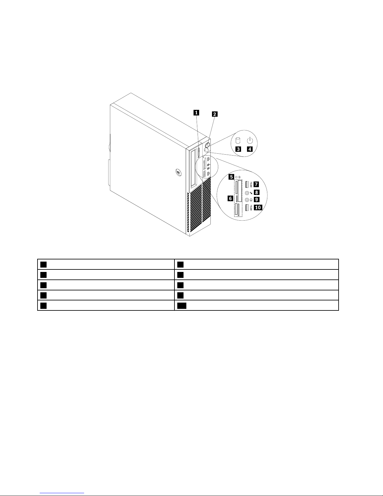
Locatingconnectors,controls,andindicatorsonthefrontofyour
computer
Figure1“Frontconnector,controls,andindicatorlocations”onpage10showsthelocationsofthe
connectors,controls,andindicatorsonthefrontofyourcomputer.
Figure1.Frontconnector,controls,andindicatorlocations
1Opticaldriveeject/closebutton6Cardreaderslots(availableinsomemodels)
2powerbutton
7USB3.0connector(USBport2)
3Harddiskdriveactivityindicator8Microphoneconnector
4Powerindicator9Headphoneconnector
5Cardreaderindicator(availableinsomemodels)10USB3.0connector(USBport1)
Locatingconnectorsontherearofyourcomputer
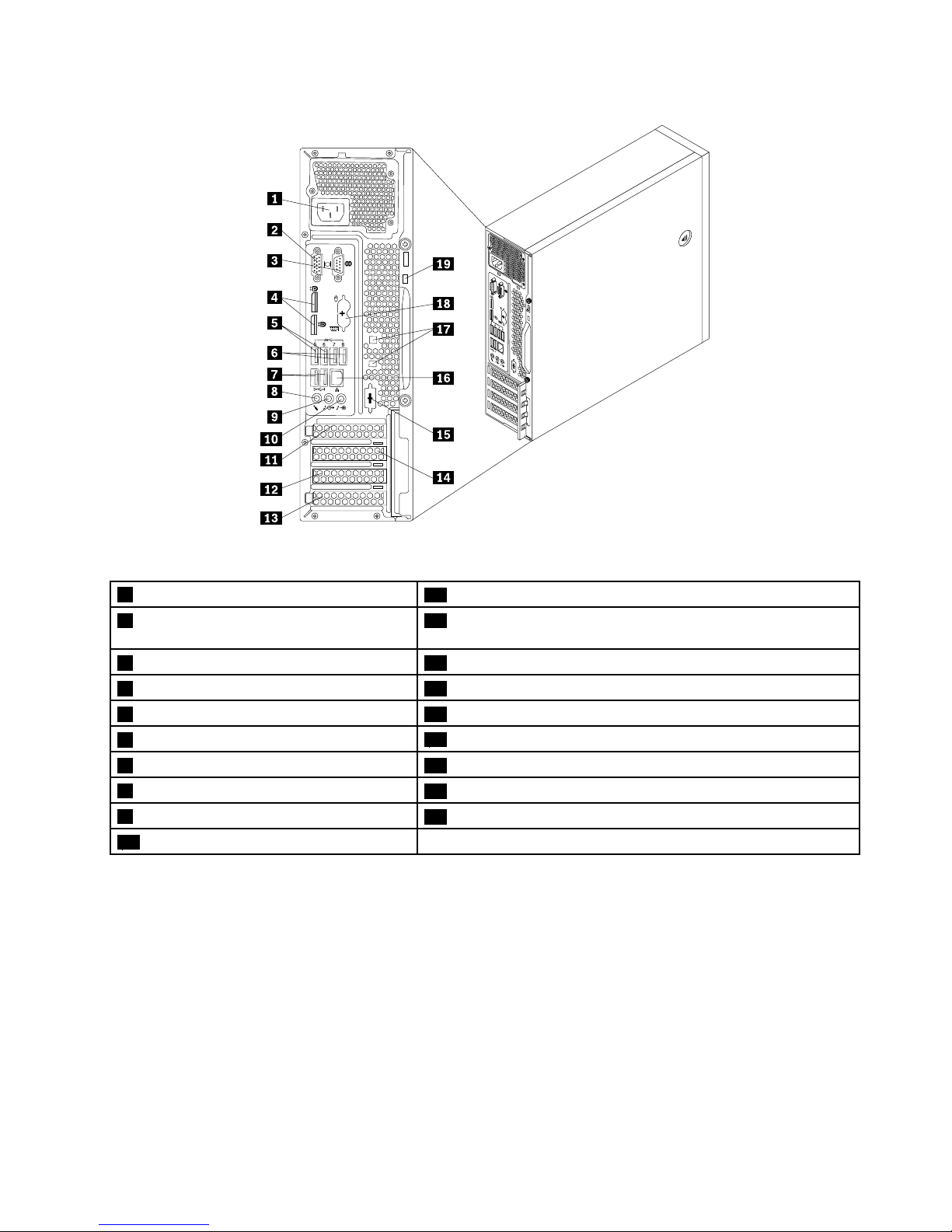
•Figure2“ThinkCentreM93/prearconnectorlocations”onpage11showsthelocationsoftheconnectors
ontherearoftheThinkCentreM93/pcomputer.Someconnectorsontherearofyourcomputerare
color-codedtohelpyoudeterminewheretoconnectthecablesonyourcomputer.
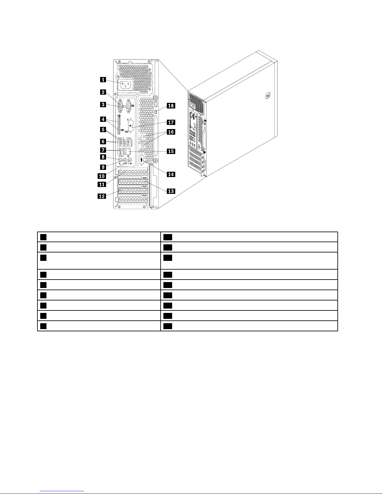
•Figure3“ThinkCentreM83rearconnectorlocations”onpage12showsthelocationsoftheconnectors
ontherearoftheThinkCentreM83computer.Someconnectorsontherearofyourcomputerare
color-codedtohelpyoudeterminewheretoconnectthecablesonyourcomputer.
10ThinkCentreM83,M93/pUserGuide
Page 23
4
3
5 6 7 8
3
4
5
6 7 8
Figure2.ThinkCentreM93/prearconnectorlocations
1Powercordconnector
11PCIExpressx16graphicscardslot
2VGAmonitorconnector12PCIExpresscardslot(physicallinkwidthx16;negotiablelink
widthx4,x1)
3Serialport113PCIcardslot
4DisplayPortconnectors(2)14PCIExpressx1cardslot
5USB3.0connectors(USBports5and6)15Optionalserialport(serialport2)
6USB3.0connectors(USBports7and8)
16Ethernetconnector
7USB2.0connectors(USBports3and4)17Cable-lockslots(2)
8Microphoneconnector
18PS/2keyboardandmouseconnectors(optional)
9Audioline-outconnector
19Security-lockslot
10Audioline-inconnector
Chapter1.Productoverview11
Page 24
4
3
3
4
5
6
7
8
6
5
8
7
Figure3.ThinkCentreM83rearconnectorlocations
1Powercordconnector10Audioline-inconnector
2VGAmonitorconnector11PCIExpressx16graphicscardslot
3Serialport112PCIExpresscardslot(physicallinkwidthx16;negotiablelink
widthx4,x1)
4DisplayPortconnectors(2)13PCIExpressx1cardslot
5USB3.0connectors(USBports5and6)14Optionalserialport(serialport2)
6USB2.0connectors(USBports7and8)
15Ethernetconnector
7USB2.0connectors(USBports3and4)16Cable-lockslots(2)
8Microphoneconnector
17PS/2keyboardandmouseconnectors(optional)
9Audioline-outconnector
18Security-lockslot
ConnectorDescription
Audioline-inconnector
Usedtoreceiveaudiosignalsfromanexternalaudiodevice,suchasastereo
system.Whenyouattachanexternalaudiodevice,acableisconnectedbetween
theaudioline-outconnectorofthedeviceandtheaudioline-inconnectorofthe
computer.
Audioline-outconnector
Usedtosendaudiosignalsfromthecomputertoexternaldevices,suchaspowered
stereospeakers(speakerswithbuilt-inampliers),headphones,multimedia
keyboards,ortheaudioline-inconnectoronastereosystemorotherexternal
recordingdevice.
DisplayPortconnector
Usedtoattachahigh-performancemonitor,adirect-drivemonitor,orotherdevices
thatuseaDisplayPortconnector.
Ethernetconnector
UsedtoattachanEthernetcableforalocalareanetwork(LAN).
Note:T ooperatethecomputerwithinFCCClassBlimits,useaCategory5Ethernet
cable.
12ThinkCentreM83,M93/pUserGuide
Page 25

ConnectorDescription
Microphoneconnector
Usedtoattachamicrophonetoyourcomputerwhenyouwanttorecordsoundorif
youusespeech-recognitionsoftware.
PS/2keyboardconnector
(optional)
UsedtoattachakeyboardthatusesaPS/2keyboardconnector.
PS/2mouseconnector
(optional)
Usedtoattachamouse,atrackball,orotherpointingdevicesthatuseaPS/2
mouseconnector.
Serialport
Usedtoattachanexternalmodem,aserialprinter,orotherdevicesthatusea
9-pinserialport.
USBconnectorUsedtoattachadevicethatrequiresaUSBconnector,suchasaUSBkeyboard,a
USBmouse,aUSBscanner,oraUSBprinter.IfyouhavemorethaneightUSB
devices,youcanpurchaseaUSBhub,whichyoucanusetoconnectadditional
USBdevices.
VGAmonitorconnectorUsedtoattachaVGAmonitororotherdevicesthatuseaVGAmonitorconnector.
Chapter1.Productoverview13
Page 26
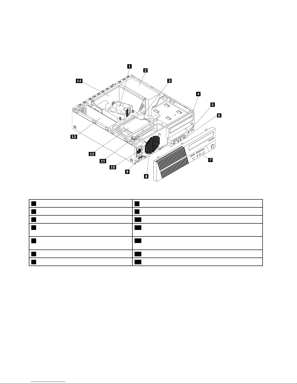
Locatingcomponents
Figure4“Componentlocations”onpage14showsthelocationsofthevariouscomponentsinyour
computer.Toremovethecomputercover,see“Removingthecomputercover”onpage36.
Figure4.Componentlocations
1Heatsinkandfanassembly
8Systemfanassembly
2Powersupplyassembly9Thermalsensor
3Memorymodule
10Internalspeaker(availableinsomemodels)
4Opticaldrive11Coverpresenceswitch(intrusionswitch)(availableinsome
models)
5Cardreaderassembly(availableinsome
models)
12Harddiskdriveorsolid-statedrive
6FrontaudioandUSBassembly13PCIcard(availableinThinkCentre
®
M93/pcomputers)
7Frontbezel
14Heatsinkfanduct
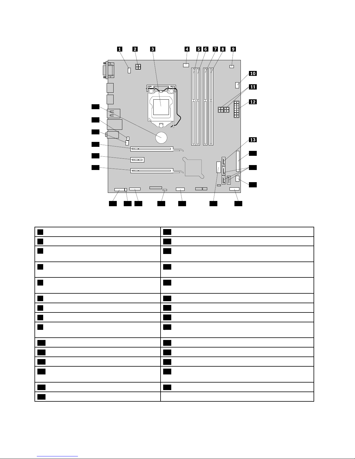
Locatingpartsonthesystemboard
•Figure5“ThinkCentreM93/psystemboardpartlocations”onpage15showsthelocationsofthepartson
thesystemboardoftheThinkCentreM93/pcomputer.
•Figure6“ThinkCentreM83systemboardpartlocations”onpage16showsthelocationsofthepartson
thesystemboardoftheThinkCentreM83computer.
14ThinkCentreM83,M93/pUserGuide
Page 27
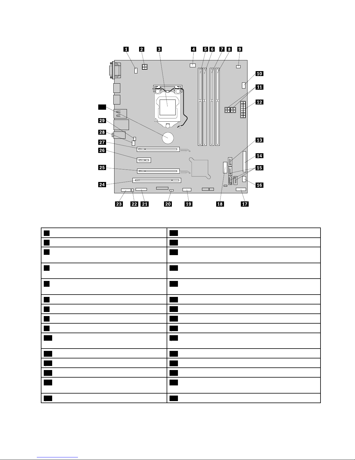
30
Figure5.ThinkCentreM93/psystemboardpartlocations
1PS/2keyboardandmouseconnector
16Powerfanconnector
24-pinpowerconnector17Frontpanelconnector
3Microprocessor
18FrontUSBconnector2(forconnectingUSBports1and2
onthefrontbezel)
4Microprocessorfanconnector
19FrontUSBconnector1(forconnectingadditionalUSB
devices)
5Memoryslot1(DIMM1)20ClearCMOS(ComplementaryMetalOxideSemiconductor)
/Recoveryjumper
6Memoryslot2(DIMM2)21Serial(COM2)connector
7Memoryslot3(DIMM3)
22Internalspeakerconnector
8Memoryslot4(DIMM4)
23Frontaudioconnector
9Thermalsensorconnector
24PCIcardslot
10Harddiskdrivefanconnector
25PCIExpresscardslot(physicallinkwidthx16;negotiable
linkwidthx4,x1)
114-pinSATApowerconnectors(2)26PCIExpressx1cardslot
1214-pinpowerconnector
27PCIExpressx16graphicscardslot
13eSATAconnector28Systemfanconnector
14Parallelconnector
29Coverpresenceswitchconnector(intrusionswitch
connector)
15SATA3.0connectors(3)
30Battery
Chapter1.Productoverview15
Page 28
14
15
16
17181920212223
24
25
26
27
28
29
Figure6.ThinkCentreM83systemboardpartlocations
1PS/2keyboardandmouseconnector
16Powerfanconnector
24-pinpowerconnector17Frontpanelconnector
3Microprocessor
18FrontUSBconnector2(forconnectingUSBports1and2
onthefrontbezel)
4Microprocessorfanconnector
19FrontUSBconnector1(forconnectingadditionalUSB
devices)
5Memoryslot1(DIMM1)20ClearCMOS(ComplementaryMetalOxideSemiconductor)
/Recoveryjumper
6Memoryslot2(DIMM2)21Serial(COM2)connector
7Memoryslot3(DIMM3)
22Internalspeakerconnector
8Memoryslot4(DIMM4)
23Frontaudioconnector
9Thermalsensorconnector
24PCIExpresscardslot(physicallinkwidthx16;negotiable
linkwidthx4,x1)
10Harddiskdrivefanconnector
25PCIExpressx1cardslot
114-pinSATApowerconnectors(2)26PCIExpressx16graphicscardslot
1214-pinpowerconnector
27Systemfanconnector
13eSATAconnector28Coverpresenceswitchconnector(intrusionswitch
connector)
14Parallelconnector29Battery
15SATA3.0connectors(3)
16ThinkCentreM83,M93/pUserGuide
Page 29
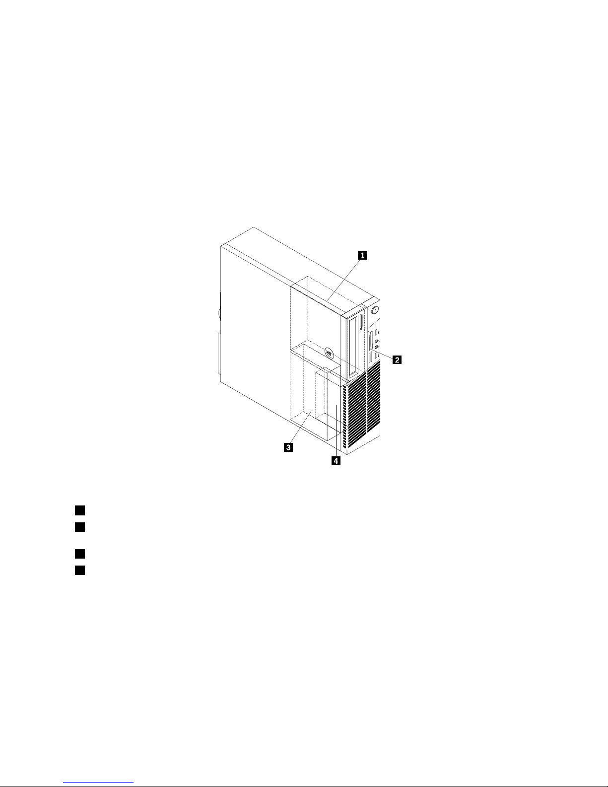
Locatinginternaldrives
Internaldrivesaredevicesthatyourcomputerusestoreadandstoredata.Youcanadddrivestoyour
computertoincreasestoragecapacityandenableyourcomputertoreadothertypesofmedia.Internal
drivesareinstalledinbays.
Wheninstallingorreplacinganinternaldrive,itisimportanttonotethetypeandsizeofthedrivethatyou
caninstallorreplaceineachbayandcorrectlyconnectthecablestothedriveinstalled.Refertothe
appropriatesectionin“Installingorreplacinghardware”onpage35forinstructionsonhowtoinstallor
replaceinternaldrivesforyourcomputer.
Figure7“Drivebaylocations”onpage17
showsthelocationsofthedrivebays.
Figure7.Drivebaylocations
1Bay1-Opticaldrivebay(withanopticaldriveinstalledonsomemodels)
2Bay2-Cardreaderdrivebay(withacardreaderassembly,frontUSBassembly,ormSATAsolid-state-drive
installedonsomemodels)
3Bay3-PrimarySATAharddiskdrivebay(witha3.5-inchSAT Aharddiskdriveinstalled)
4Bay4-SecondarySATAharddiskdrivebay(withanoptional2.5-inchSATAharddiskdriveinstalled)
Chapter1.Productoverview17
Page 30
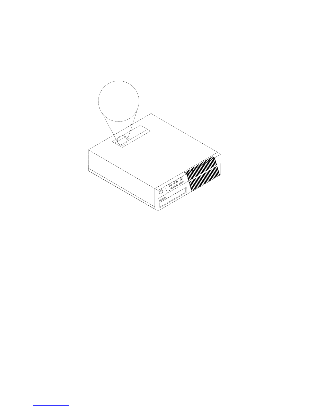
Machinetypeandmodellabel
Themachinetypeandmodellabelidentiesyourcomputer.WhenyoucontactLenovoforhelp,themachine
typeandmodelinformationhelpssupporttechnicianstoidentifyyourcomputerandprovidefasterservice.
Thefollowingisasampleofthemachinetypeandmodellabel.
Machine Type: XXXX
Model Number: XXX
Figure8.Machinetypeandmodellabel
18ThinkCentreM83,M93/pUserGuide
Page 31

Chapter2.Usingyourcomputer
Thischapterprovidesinformationonusingsomeofthecomputercomponents.
Frequentlyaskedquestions
Thefollowingareafewtipsthatwillhelpyouoptimizetheuseofyourcomputer.
CanIgetmyuserguideinanotherlanguage?
TheuserguideisavailableinvariouslanguagesontheLenovoSupportWebsiteat:
http://www.lenovo.com/ThinkCentreUserGuides
Wherearemyrecoverydiscs?
Lenovoprovidesaprogramthatenablesyoutocreaterecoverydiscs.Fordetailsaboutcreatingrecovery
discs,see“Creatingrecoverymedia”onpage108.
Additionally,incaseofaharddiskfailure,youcanorderProductRecoverydiscsfromtheLenovoCustomer
SupportCenter.ForinformationaboutcontactingtheCustomerSupportCenter,seeChapter11“Getting
information,help,andservice”onpage145.BeforeusingtheProductRecoverydiscs,refertothe
documentationthatcomeswiththediscs.
Attention:AProductRecoverydiscpackagemightcontainmultiplediscs.Makesureyouhaveallofthe
discsreadybeforestartingtherecoveryprocess.Duringtherecoveryprocess,youmightbeprompted
tochangediscs.
WherecanIndhelpabouttheWindowsoperatingsystem?
TheWindowsHelpandSupportinformationsystemprovidesyouwithdetailedinformationaboutusingthe
Windowsoperatingsystemtohelpyougetthemostofyourcomputer.ToaccesstheWindowsHelpand
Supportinformationsystem,dooneofthefollowing:
•OntheWindows7operatingsystem,clickStart➙HelpandSupport.
•OntheWindows8operatingsystem,moveyourcursortothetop-rightorbottom-rightcornerofthe
screentodisplaythecharms.ThenclickSettings➙Help.
AccessingControlPanelontheWindows8operatingsystem
OntheWindowsoperatingsystem,youcanviewandchangecomputersettingsthroughControlPanel.To
accessControlPanelontheWindows8operatingsystem,dooneofthefollowing:
•Fromthedesktop
1.Movethecursortothetop-rightorbottom-rightcornerofthescreentodisplaythecharms.
2.ClickSettings.
3.ClickControlPanel.
•FromtheStartscreen
1.Movethecursortothetop-rightorbottom-rightcornerofthescreentodisplaythecharms.
2.ClickSearch.
3.OntheAppsscreen,scrolltotherightside,andclickControlPanelintheWindowsSystemsection.
©CopyrightLenovo2013
19
Page 32

Usingthekeyboard
Dependingonyourmodel,yourcomputercomeswitheitherastandardkeyboardorangerprintreader
keyboard.TheMicrosoftWindowsshortcutkeysareprovidedonbothkeyboardtypes.
Thissectionprovidesinformationaboutthefollowingtopics:
•“UsingWindowsshortcutkeys”onpage20
•“UsingtheblueThinkVantagebutton”onpage20
•“Usingangerprintreader”onpage20
UsingWindowsshortcutkeys
Boththestandardkeyboardandthengerprintreaderkeyboardprovidethreekeysyoucanusewithyour
MicrosoftWindowsoperatingsystem.
•ThetwoWindowslogokeysarelocatedbesidetheAltkeyoneithersideofthespacebar.Theyfeature
theWindowslogo.OntheWindows7operatingsystem,presstheWindowskeytoopentheStartmenu.
OntheWindows8operatingsystem,presstheWindowskeytoswitchbetweenthecurrentworkspace
andtheStartscreen.ThestyleoftheWindowslogovariesdependingonthekeyboardtype.
•Thecontext-menukeyislocatednexttotheCtrlkeyontherightsideoftheSpacebar.Pressingthe
context-menukeyopensthecontextmenufortheactiveprogram,icon,orobject.
Note:YoucanusethemouseortheUpandDownarrowkeystohighlightmenuselections.OntheWindows
7operatingsystem,youcanclosetheStartmenuorthecontextmenubyclickingthemouseorpressingEsc.
UsingtheblueThinkVantagebutton
SomekeyboardshaveablueThinkVantagebuttonthatyoucanusetoopenacomprehensiveon-boardhelp
andinformationcenterfromLenovo.PressingtheblueThinkVantagebuttonopenstheSimpleT approgram
ontheWindows7operatingsystemortheLenovoPCDeviceExperienceprogramontheWindows8
operatingsystem.
Usingangerprintreader
Somecomputersmightcomewithakeyboardthathasangerprintreader.Formoreinformationaboutthe
ngerprintreader,see“AnintroductiontoLenovoprograms”onpage7.
ToopentheThinkVantageFingerprintSoftwareprogramandusethengerprintreader,see“Lenovo
programs”onpage5.
Followtheinstructionsonthescreen.Foradditionalinformation,refertotheThinkVantageFingerprint
Softwarehelpsystem.
20ThinkCentreM83,M93/pUserGuide
Page 33
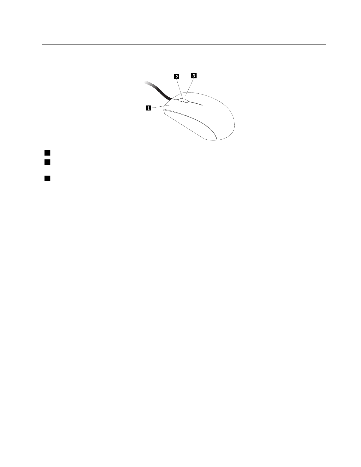
Usingthewheelmouse
Thewheelmousehasthefollowingcontrols:
1PrimarymousebuttonUsethisbuttontoselectorstartaprogramormenuitem.
2Wheel
Usethewheeltocontrolthescrollingactionofthemouse.Thedirectioninwhichyou
rotatethewheelcontrolsthedirectionofthescrollingaction.
3Secondarymousebutton
Usethisbuttontodisplayamenufortheactiveprogram,icon,orobject.
Youcanswitchthefunctionoftheprimaryandsecondarymousebuttonsandchangeotherdefaultbehavior
throughthemousepropertiesfunctionintheWindowsControlPanel.
Adjustingaudio
Soundisanimportantpartofthecomputerexperience.Y ourcomputerhasadigitalaudiocontrollerbuilt
intothesystemboard.Somemodelsalsohaveahigh-performanceaudioadapterinstalledinoneofthePCI
cardslots.
Aboutyourcomputeraudio
Ifafactory-installed,high-performanceaudioadapterisinstalledinyourcomputer,thesystem-board
audioconnectorsontherearofthecomputeraretypicallydisabled;usetheconnectorsprovidedonthe
audioadapter.
Eachaudiosolutionprovidesatleastthreeaudioconnectors:audioline-inconnector,audioline-out
connector,andMicrophoneconnector.Onsomemodels,afourthconnectorisprovidedfortheattachment
ofunpoweredstereospeakers(speakersthatdonotrequireanacpowersource).Theaudioadapter
providesyouwiththeabilitytorecordandplaybacksoundandmusic,aswellastoenjoysoundwith
multimediaapplicationsandworkwithspeech-recognitionsoftware.
Optionally,youcanconnectasetofpoweredstereospeakerstotheaudioline-outconnectortoenjoy
bettersoundwithmultimediaapplications.
Settingthevolumefromthedesktop
Thedesktopvolumecontrolisaccessiblethroughthevolumeiconinthetaskbar,whichislocatedatthe
bottom-rightcorneroftheWindowsdesktop.Clickthevolumeiconandmovethesliderupordownto
controlthevolume,orclicktheMuteicontoturntheaudiooff.Ifthevolumeiconisnotinthetaskbar,see
“Addingthevolumeicontothetaskbar”onpage21
.
Addingthevolumeicontothetaskbar
ToaddthevolumeicontothetaskbarontheWindows7operatingsystem,dothefollowing:
Chapter2.Usingyourcomputer21
Page 34

1.FromtheWindowsdesktop,clickStart➙ControlPanel➙AppearanceandPersonalization.
2.IntheTaskbarandStartMenusection,clickCustomizeiconsonthetaskbar.
3.ClickTurnsystemiconsonoroffandchangethevolumebehaviorsfromOfftoOn.
4.ClickOKtosavethenewsettings.
ToaddthevolumeicontothetaskbarontheWindows8operatingsystem,dothefollowing:
1.OpenControlPanel,andclickAppearanceandPersonalization.
2.IntheTaskbarsection,clickCustomizeiconsonthetaskbar.
3.ClickTurnsystemiconsonoroffandchangethevolumebehaviorsfromOfftoOn.
4.ClickOKtosavethenewsettings.
SettingthevolumefromControlPanel
YoucansetthecomputervolumefromControlPanel.TosetthecomputervolumefromControlPanel,
dothefollowing:
1.OntheWindows7operatingsystem,clickStart➙ControlPanel➙HardwareandSound.Onthe
Windows8operatingsystem,openControlPanel,andclickHardwareandSound.
2.IntheSoundsection,clickAdjustsystemvolume.
3.Movetheslidersupordowntoraiseorlowerthevolumeofyourcomputer.
UsingCDsandDVDs
YourcomputermighthaveaDVDROMdriveorrecordableDVDdriveinstalled.DVDdrivesuse
industry-standard,12cm(4.75-inch)CDmediaorDVDmedia.IfyourcomputercomeswithaDVDdrive,
thedrivecanreadDVD-ROMdiscs,DVD-Rdiscs,DVD-RAMdiscs,DVD-RWdiscs,andalltypesofCDs,
suchasCD-ROMdiscs,CD-RWdiscs,CD-Rdiscs,andaudioCDs.IfyouhavearecordableDVDdrive,
itcanalsorecordonDVD-Rdiscs,DVD-RWdiscs,typeIIDVD-RAMdiscs,CD-RWstandardandhigh
speeddiscs,andCD-Rdiscs.
FollowtheseguidelineswhenusingtheDVDdrive:
•Donotplacethecomputerinalocationwherethedriveisexposedtothefollowing:
–Hightemperature
–Highhumidity
–Excessivedust
–Excessivevibrationorsuddenshock
–Aninclinedsurface
–Directsunlight
•DonotinsertanyobjectotherthanaCDorDVDintothedrive.
•Beforemovingthecomputer,removetheCDorDVDfromthedrive.
HandlingandstoringCDandDVDmedia
CDandDVDmediaaredurableandreliable,buttheydorequiresomecareandspecialhandling.When
handlingandstoringaCDorDVD,followtheseguidelines:
•Holdthediscbyitsedges.Donottouchthesurfaceofthesidethatisnotlabeled.
•Toremovedustorngerprints,wipethediscwithaclean,softclothfromthecentertotheoutside.Wiping
thediscinacirculardirectionmightcauselossofdata.
22ThinkCentreM83,M93/pUserGuide
Page 35

•Donotwriteorstickpaperonthedisc.
•Donotscratchormarkthedisc.
•Donotplaceorstorethediscindirectsunlight.
•Donotusebenzene,thinners,orothercleanerstocleanthedisc.
•Donotdroporbendthedisc.
•Donotinsertdamageddiscsintothedrive.Warped,scratched,ordirtydiscscandamagethedrive.
PlayingaCDorDVD
IfyourcomputercomeswithaDVDdrive,youcanlistentoaudioCDsorwatchDVDmovies.Toplaya
CDorDVD,dothefollowing:
1.PresstheEject/LoadbuttonontheDVDdrivetoopenthetray.
2.Withthetrayfullyextended,inserttheCDorDVDintothetray.SomeDVDdriveshaveasnaphubinthe
centerofthetray.Ifyourdrivehasasnaphub,supportthetraywithonehandandthenpushonthe
centeroftheCDorDVDuntilitsnapsintoplace.
3.PresstheEject/Loadbuttonagainorgentlypushthetrayforwardtoclosethetray.TheCDorDVD
playerprogramstartsautomatically.Foradditionalinformation,refertotheCDorDVDplayerprogram
helpsystem.
ToremoveaCDorDVDfromtheDVDdrive,dothefollowing:
1.Withthecomputeron,presstheEject/Loadbutton.Whenthetrayslidesoutautomatically,carefully
removethedisc.
2.ClosethetraybypressingtheEject/Loadbuttonorbygentlypushingthetrayforward.
Note:IfthetraydoesnotslideoutofthedrivewhenyoupresstheEject/Loadbutton,insertastraightened
paperclipintotheemergency-ejectholelocatedonthefrontoftheDVDdrive.Besurethedriveispowered
offwhenusingtheemergencyeject.UsetheEject/Loadbuttoninsteadoftheemergencyejectexcept
inanemergency.
RecordingaCDorDVD
IfyourcomputercomeswitharecordableDVDdrive,youcanusethedrivetorecordCDsorDVDs.
TorecordaCDorDVD,dooneofthefollowing:
•OntheWindows7operatingsystem,youhaveeithertheCorelDVDMovieFactoryLenovoEditionprogram
orthePower2Goprograminstalledonyourcomputer.
–ToruntheCorelDVDMovieFactoryLenovoEditionprogram,clickStart➙AllPrograms➙Corel
DVDMovieFactoryLenovoEdition➙CorelDVDMovieFactoryLenovoEdition.Followthe
instructionsonthescreen.
–TorunthePower2Goprogram,clickStart➙AllPrograms➙PowerDVDCreate➙Power2Go.
Followtheinstructionsonthescreen.
•OntheWindows8operatingsystem,runthePower2Goprogrambydoingthefollowing:
1.Movethecursortothetop-rightorbottom-rightcornerofthescreentodisplaythecharms.Then
clickSearchandtypePower2Go.
2.ClickPower2Gointheleftpaneltoopentheprogram.
3.Followtheinstructionsonthescreen.
YoualsocanuseWindowsMedia
®
PlayertorecordCDsanddataDVDs.Formoreinformation,see“Help
andSupport”onpage145.
Chapter2.Usingyourcomputer23
Page 36

24ThinkCentreM83,M93/pUserGuide
Page 37

Chapter3.Youandyourcomputer
Thischapterprovidesinformationaboutaccessibility,comfort,andrelocatingyourcomputertoother
countriesorregions.
Accessibilityandcomfort
Goodergonomicpracticeisimportanttogetthemostfromyourpersonalcomputerandtoavoiddiscomfort.
Arrangeyourworkplaceandtheequipmentyouusetosuityourindividualneedsandthekindofwork
thatyouperform.Inaddition,usehealthyworkhabitstomaximizeyourperformanceandcomfortwhile
usingyourcomputer.
Thefollowingtopicsprovideinformationaboutarrangingyourworkarea,settingupyourcomputer
equipment,andestablishinghealthyworkhabits.
Lenovoiscommittedtoprovidingpeoplewithdisabilitiesgreateraccesstoinformationandtechnology.
Asaresult,thefollowinginformationprovideswaystohelpusersthathavehearing,vision,andmobility
limitationsgetthemostoutoftheircomputerexperience.
Assistivetechnologiesenableuserstoaccessinformationinthemostappropriateway.Someofthese
technologiesarealreadyprovidedinyouroperatingsystem,otherscanbepurchasedthroughvendors,or
accessedthroughtheWorldWideWeb:
http://www.lenovo.com/healthycomputing
Arrangingyourworkspace
Togetthemostfromyourcomputer,arrangeboththeequipmentyouuseandyourworkareatosuityour
needsandthekindofworkyoudo.Y ourcomfortisofforemostimportance,butlightsources,aircirculation,
andthelocationofelectricaloutletscanalsoaffectthewayyouarrangeyourworkspace.
Comfort
Althoughnosingleworkingpositionisidealforeveryone,hereareafewguidelinestohelpyounda
positionthatsuitsyoubest.
Sittinginthesamepositionforalongtimecancausefatigue.Thebackrestandseatofyourchairshould
adjustindependentlyandprovidegoodsupport.Theseatshouldhaveacurvedfronttorelievepressureon
thethighs.Adjusttheseatsothatyourthighsareparalleltotheoorandyourfeetareeitheratonthe
oororonafootrest.
Whenusingthekeyboard,keepyourforearmsparalleltotheoorandyourwristsinacomfortableposition.
Usealighttouchonthekeyboardandyourhandsandngersrelaxed.Changetheangleofthekeyboard
formaximumcomfortbyadjustingthepositionofthekeyboardfeet.
©CopyrightLenovo2013
25
Page 38
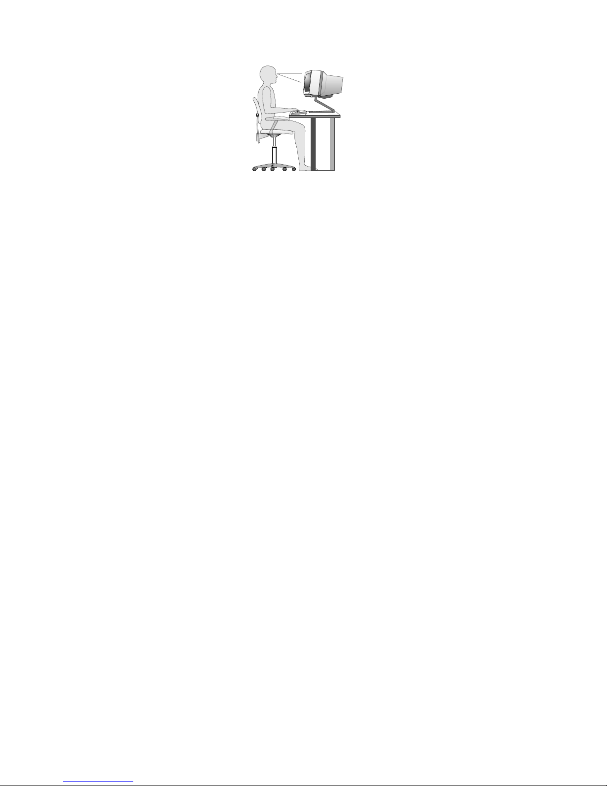
Adjustthemonitorsothetopofthescreenisat,orslightlybelow,eyelevel.Placethemonitorata
comfortableviewingdistance,usually51to61cm(20to24inches),andpositionitsoyoucanviewit
withouthavingtotwistyourbody.Also,positionotherequipmentyouuseregularly,suchasthetelephoneor
amouse,withineasyreach.
Glareandlighting
Positionthemonitortominimizeglareandreectionsfromoverheadlights,windows,andotherlightsources.
Reectedlightfromshinysurfacescancauseannoyingreectionsonyourmonitorscreen.Placethe
monitoratrightanglestowindowsandotherlightsources,whenpossible.Reduceoverheadlighting,if
necessary,byturningofflightsorusinglowerwattagebulbs.Ifyouinstallthemonitornearawindow,use
curtainsorblindstoblockthesunlight.Y oucanadjustthebrightnessandcontrastcontrolsonthemonitor
astheroomlightingchangesthroughouttheday.
Whereitisimpossibletoavoidreectionsortoadjustthelighting,anantiglarelterplacedoverthescreen
mightbehelpful.However,theseltersmightaffecttheclarityoftheimageonthescreen;trythemonlyafter
youhaveexhaustedothermethodsofreducingglare.
Dustbuildupcompoundsproblemsassociatedwithglare.Remembertocleanyourmonitorscreen
periodicallyusingasoftclothasdirectedinyourmonitordocumentation.
Aircirculation
Yourcomputerandmonitorproduceheat.Thecomputerhasafanthatpullsinfreshairandforcesouthot
air.Themonitorletshotairescapethroughvents.Blockingtheairventscancauseoverheating,whichmight
resultinamalfunctionordamage.Placethecomputerandmonitorsothatnothingblockstheairvents;
usually,51mm(2inches)ofairspaceissufcient.Also,makesuretheventedairisnotblowingonpeople.
Electricaloutletsandcablelengths
Thelocationofelectricaloutlets,thelengthofpowercordsandcablesthatconnecttothemonitor,printer,
andotherdevicesmightdeterminethenalplacementofyourcomputer.
Whenarrangingyourworkspace:
•Avoidtheuseofextensioncords.Whenpossible,plugthecomputerpowercorddirectlyintoanelectrical
outlet.
•Keeppowercordsandcablesneatlyroutedawayfromwalkwaysandotherareaswheretheymight
getkickedaccidentally.
Formoreinformationaboutpowercords,see“Powercordsandpoweradapters”onpagevi
.
26ThinkCentreM83,M93/pUserGuide
Page 39

Registeringyourcomputer
Whenyouregisteryourcomputer,informationisenteredintoadatabase,whichenablesLenovotocontact
youincaseofarecallorothersevereproblem.AfteryouregisteryourcomputerwithLenovo,youwillreceive
quickerservicewhenyoucallLenovoforhelp.Inaddition,somelocationsofferextendedprivilegesand
servicestoregisteredusers.
ToregisteryourcomputerwithLenovo,dooneofthefollowing:
•Gotohttp://www.lenovo.com/registerandfollowtheinstructionsonthescreentoregisteryourcomputer.
•ConnectyourcomputertotheInternetandregisteryourcomputerthroughapreinstalledregistration
program:
–ForWindows7:ThepreinstalledLenovoProductRegistrationprogramlaunchesautomaticallyafteryou
haveusedyourcomputerforatime.Followtheinstructionsonthescreentoregisteryourcomputer.
–ForWindows8:OpentheLenovoSupportprogram.ThenclickRegistrationandfollowtheinstructions
onthescreentoregisteryourcomputer.
Movingyourcomputertoanothercountryorregion
Whenyoumoveyourcomputertoanothercountryorregion,youmusttakelocalelectricalstandardsinto
consideration.Thissectionprovidesinformationonthefollowing:
•“Replacementpowercords”onpage27
Replacementpowercords
Ifyourelocateyourcomputertoacountryorregionthatusesanelectricaloutletstyledifferentfromthe
typeyouarecurrentlyusing,youwillhavetopurchaseeitherelectricalplugadaptersornewpowercords.
YoucanorderpowercordsdirectlyfromLenovo.
Forpowercordinformationandpartnumbers,goto:
http://www.lenovo.com/powercordnotice
Chapter3.Youandyourcomputer27
Page 40

28ThinkCentreM83,M93/pUserGuide
Page 41

Chapter4.Security
Thischapterprovidesinformationabouthowtoprotectyourcomputerfromtheftandunauthorizeduse.
Securityfeatures
Thefollowingsecurityfeaturesareavailableonyourcomputer:
•ComputraceAgentsoftwareembeddedinrmware
TheComputraceAgentsoftwareisanITassetmanagementandcomputertheftrecoverysolution.
Thesoftwaredetectsifchangeshavebeenmadeonthecomputer,suchashardware,software,or
thecomputercall-inlocation.
Note:YoumighthavetopurchaseasubscriptiontoactivatetheComputraceAgentsoftware.
•AbilitytoenableanddisabledevicesandUSBconnectors
Formoreinformation,see“Enablingordisablingadevice”onpage117.
•Integratedngerprintreader(availableonsomemodels)
Dependingonthemodelsofyourcomputer,thekeyboardmayhaveanintegratedngerprintreader.
ByenrollingyourngerprintandassociatingitwithaPower-onPassword,aHardDiskPassword,or
bothpasswordsbeforehand,youcanstartthecomputer,logontothesystem,andentertheSetup
Utilityprogrambyswipingyourngeroverthereader,withouttypingapassword.Thusngerprint
authenticationcanreplacepasswordsandenablesimpleandsecureuseraccess.
•Startupsequencecontrol
Formoreinformation,see“Selectingorchangingthestartupdevicesequence”onpage118
.
•Startupwithoutkeyboardormouse
Yourcomputerisabletologintotheoperatingsystemwithoutkeyboardormouseconnected.
•TrustedPlatformModule(TPM)
TrustedPlatformModuleisasecurecryptoprocessorthatcanstorecryptographickeysthatprotect
informationstoredinyourcomputer.
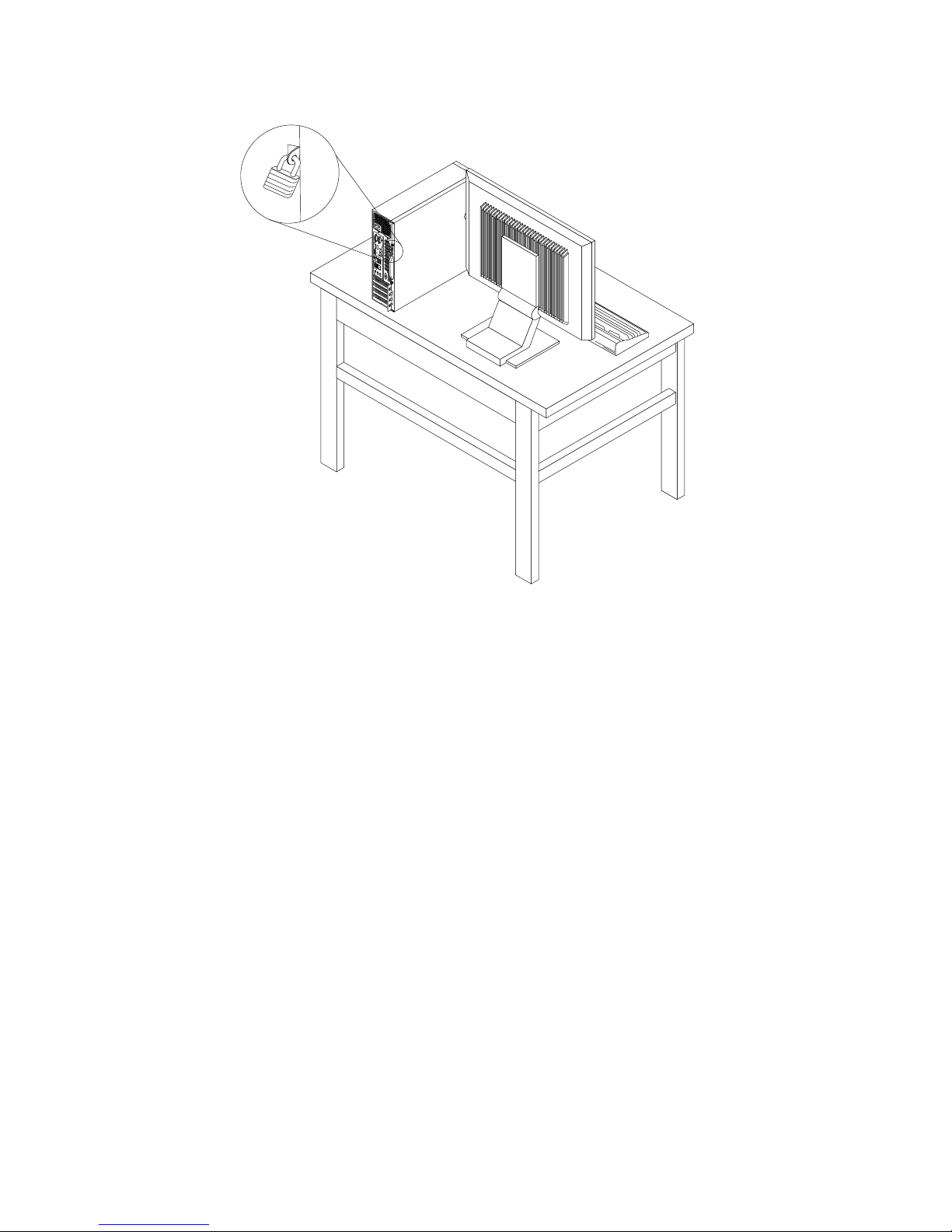
Lockingthecomputercover
Lockingthecomputercoverhelpspreventunauthorizedpeoplefromgainingaccesstotheinsideofyour
computer.Y ourcomputercomeswithapadlockloopsothatthecomputercovercannotberemoved
whenapadlockisinstalled.
©CopyrightLenovo2013
29
Page 42
3
4
5
6
7
8
Figure9.Installingapadlock
30ThinkCentreM83,M93/pUserGuide
Page 43
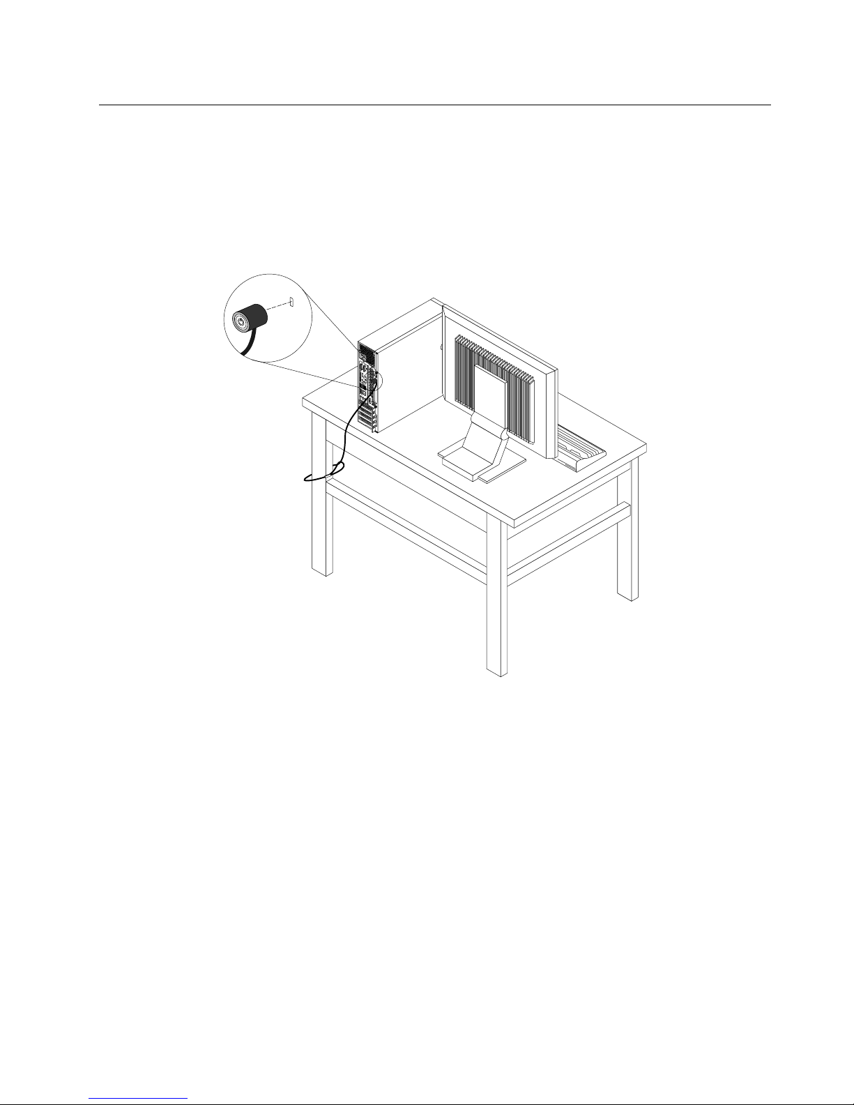
AttachingaKensington-stylecablelock
YoucanuseaKensington-stylecablelocktosecureyourcomputertoadesk,table,orothernon-permanent
xture.Thecablelockattachestothesecurity-lockslotattherearofyourcomputerandisoperatedwitha
keyorcombinationdependingonthetypeselected.Thecablelockalsolocksthebuttonsusedtoopenthe
computercover.Thisisthesametypeoflockusedwithmanynotebookcomputers.Youcanordersucha
cablelockdirectlyfromLenovobysearchingforKensingtonat:
http://www.lenovo.com/support
3
4
5
6 7
8
Figure10.Kensington-stylecablelock
Chapter4.Security31
Page 44
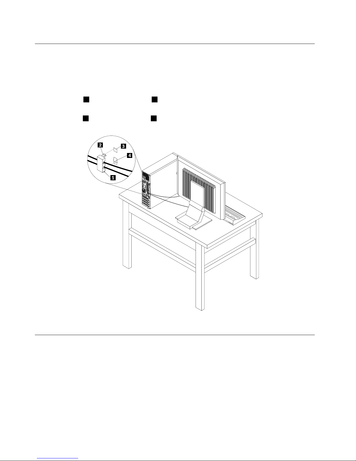
Attachingacablelock
Youcanuseacablelocktosecuredevices,suchasthekeyboardandthemouse,bylockingthedevice
cablestoyourcomputer.Thecablelockattachestothecable-lockslotsontherearofyourcomputer.See
“Locatingconnectorsontherearofyourcomputer”onpage10
.
Toinstallacablelock,dothefollowing:
1.Inserttheclip1intothecable-lockslot4.
2.Pullthecablesyouwanttolockthroughthedentsinthecablelock.
3.Presstheclip2intothecable-lockslot3untilitsnapsintoposition.
3
4
5
6
7 8
Figure11.Installingacablelock
Usingpasswords
YoucansetavarietyofpasswordsthroughtheMicrosoftWindowsoperatingsystemandthroughtheBIOS
ofyourcomputertohelpdeterunauthorizeduseofyourcomputer.
BIOSpasswords
YoucanusetheBIOSSetupUtilityprogramtosetpasswordstopreventunauthorizedaccesstoyour
computeranddata.Thefollowingtypesofpasswordsareavailable:
•Power-OnPassword:WhenaPower-OnPasswordisset,youarepromptedtotypeavalidpassword
eachtimethecomputeristurnedon.Thecomputercannotbeuseduntilthevalidpasswordistyped
in.Formoreinformation,see“Power-OnPassword”onpage116
.
32ThinkCentreM83,M93/pUserGuide
Page 45

•HardDiskPassword:SettingaHardDiskPasswordpreventsunauthorizedaccesstothedataonthehard
diskdrive.WhenaHardDiskPasswordisset,youarepromptedtotypeavalidpasswordeachtimeyou
trytoaccesstheharddiskdrive.Formoreinformation,see“HardDiskPassword”onpage116.
•AdministratorPassword:SettinganAdministratorPassworddetersunauthorizedusersfromchanging
congurationsettings.Ifyouareresponsibleformaintainingthecongurationsettingsofseveral
computers,youmightwanttosetanAdministratorPassword.Formoreinformation,see“Administrator
Password”onpage116
.
Youdonothavetosetanypasswordstouseyourcomputer.However,usingpasswordsimproves
computingsecurity.
Windowspasswords
DependingonyourversionoftheWindowsoperatingsystem,youcanusepasswordsforavarietyof
features,includingcontrollingloginaccess,accesstosharedresources,networkaccess,andindividualuser
settings.Formoreinformation,see“HelpandSupport”onpage145.
Conguringthengerprintreader
Ifyourkeyboardhasangerprintreader,youcancongurethengerprintreaderintheSetupUtilityprogram.
TheFingerprintSetupsubmenuundertheSecuritymenuoftheSetupUtilityprogramprovidesthe
followingoptions:
•PrebootAuthentication:enablesordisablesthengerprintauthenticationforaccessingtheBIOS.
•EraseFingerprintData:clearsthengerprintdatastoredinangerprintreader.
Tocongurethengerprintreader,dothefollowing:
1.StarttheSetupUtilityprogram.See“StartingtheSetupUtilityprogram”onpage115.
2.FromtheSetupUtilityprogrammainmenu,selectSecurity➙FingerprintSetup,andpressEnter.
TheFingerprintSetupwindowopens.
3.SelectPrebootAuthenticationorEraseFingerprintDataasdesired,andpressEnter.
4.SelectthedesiredsettingsandpressEnter.
5.PressF10tosavechangesandexittheSetupUtilityprogram.PressEnterwhenpromptedtoconrm
theexit.
Usingandunderstandingrewalls
Arewallcanbehardware,software,oracombinationofbothdependingonthelevelofsecurityrequired.
Firewallsworkonasetofrulestodeterminewhichinboundandoutboundconnectionsareauthorized.If
yourcomputerispreinstalledwitharewallprogram,ithelpsprotectagainstcomputerInternetsecurity
threats,unauthorizedaccess,intrusions,andInternetattacks.Italsoprotectsyourprivacy.Formore
informationabouthowtousetherewallprogram,refertothehelpsystemofyourrewallprogram.
TheWindowsoperatingsystempreinstalledonyourcomputerprovidestheWindowsFirewall.Fordetailson
usingtheWindowsFirewall,referto“HelpandSupport”onpage145.
Protectingdataagainstviruses
Yourcomputerispreinstalledwithanantivirusprogramtohelpyouguardagainst,detect,andeliminate
viruses.
Chapter4.Security33
Page 46

Lenovoprovidesafullversionofantivirussoftwareonyourcomputerwithafree30-daysubscription.After
30days,youmustrenewthelicensetocontinuereceivingtheantivirussoftwareupdates.
Note:Virusdenitionlesmustbekeptup-to-datetoguardagainstnewviruses.
Formoreinformationabouthowtouseyourantivirussoftware,refertothehelpsystemofyourantivirus
software.
34ThinkCentreM83,M93/pUserGuide
Page 47

Chapter5.Installingorreplacinghardware
Thischapterprovidesinstructionsonhowtoinstallorreplacehardwareforyourcomputer.
Note:Note:Dependingonthemodel,yourcomputermightlookslightlydifferentfromtheillustrationsin
thischapter.
Handlingstatic-sensitivedevices
Donotopenthestatic-protectivepackagecontainingthenewpartuntilthedefectiveparthasbeenremoved
fromthecomputerandyouarereadytoinstallthenewpart.Staticelectricity,althoughharmlesstoyou,can
seriouslydamagecomputercomponentsandparts.
Whenyouhandlepartsandothercomputercomponents,taketheseprecautionstoavoidstatic-electricity
damage:
•Limityourmovement.Movementcancausestaticelectricitytobuilduparoundyou.
•Alwayshandlepartsandothercomputercomponentscarefully.HandlePCIcards,memorymodules,
systemboards,andmicroprocessorsbytheedges.Nevertouchanyexposedcircuitry.
•Preventothersfromtouchingthepartsandothercomputercomponents.
•Beforeyoureplaceanewpart,touchthestatic-protectivepackagecontainingtheparttoametal
expansion-slotcoverorotherunpaintedmetalsurfaceonthecomputerforatleasttwoseconds.This
reducesstaticelectricityfromthepackageandyourbody.
•Whenpossible,removethenewpartfromthestatic-protectivepackage,andinstallitdirectlyinthe
computerwithoutsettingthepartdown.Whenthisisnotpossible,placethestatic-protectivepackage
thatthepartcameinonasmooth,levelsurfaceandplacethepartonthepackage.
•Donotplacethepartonthecomputercoverorothermetalsurface.
Installingorreplacinghardware
Thissectionprovidesinstructionsonhowtoinstallorreplacehardwareforyourcomputer.Youcanexpand
thecapabilitiesofyourcomputerandmaintainyourcomputerbyinstallingorreplacinghardware.
Attention:
Donotopenyourcomputerorattemptanyrepairbeforereadingandunderstandingthe“Importantsafetyinformation”
onpagev.
Notes:
•UseonlycomputerpartsprovidedbyLenovo.
•Wheninstallingorreplacinganoption,usetheappropriateinstructionsinthissectionalongwiththe
instructionsthatcomewiththeoption.
Installingexternaloptions
Youcanconnectexternaloptionstoyourcomputer,suchasexternalspeakers,aprinter,orascanner.For
someexternaloptions,youmustinstalladditionalsoftwareinadditiontomakingthephysicalconnection.
Wheninstallinganexternaloption,see“Locatingconnectors,controls,andindicatorsonthefrontofyour
computer”onpage10
and“Locatingconnectorsontherearofyourcomputer”onpage10toidentifythe
requiredconnector.Then,usetheinstructionsthatcomewiththeoptiontohelpyoumaketheconnection
andinstallanysoftwareordevicedriversthatarerequiredfortheoption.
©CopyrightLenovo2013
35
Page 48
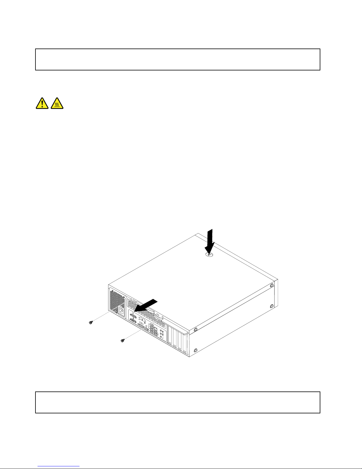
Removingthecomputercover
Attention:
Donotopenyourcomputerorattemptanyrepairbeforereadingandunderstandingthe“Importantsafetyinformation”
onpagev
.
Thissectionprovidesinstructionsonhowtoremovethecomputercover.
CAUTION:
Turnoffthecomputerandwaitthreetoveminutestoletthecomputercoolbeforeremovingthe
computercover.
Toremovethecomputercover,dothefollowing:
1.Removeanymediafromthedrivesandturnoffallattacheddevicesandthecomputer.
2.Disconnectallpowercordsfromelectricaloutlets.
3.Disconnectthepowercord,Input/Outputcables,andanyothercablesthatareconnectedtothe
computer.
4.Removeanylockingdevicethatsecuresthecomputercover,suchasapadlockoraKensington-style
cablelock.See“Lockingthecomputercover”onpage29,“AttachingaKensington-stylecablelock”on
page31,and“Attachingacablelock”onpage32.
5.Removethescrewsthatsecurethecomputercover.Then,pressthecover-releasebuttononthesideof
thecomputerandslidethecomputercovertotherearofthecomputertoremoveit.
3
4
5 6 7
8
Figure12.Removingthecomputercover
Removingandreinstallingthefrontbezel
Attention:
Donotopenyourcomputerorattemptanyrepairbeforereadingandunderstandingthe“Importantsafetyinformation”
onpagev.
Thissectionprovidesinstructionsonhowtoremoveandreinstallthefrontbezel.
36ThinkCentreM83,M93/pUserGuide
Page 49
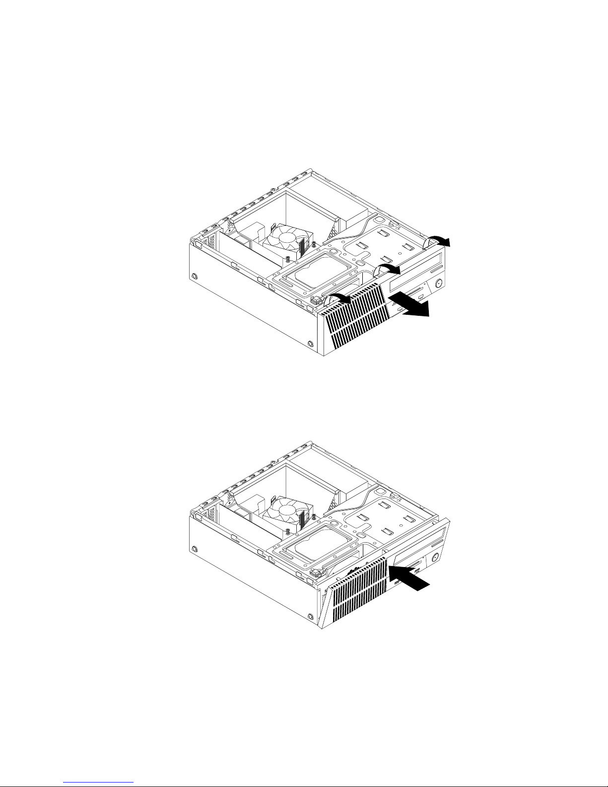
Toremoveandreinstallthefrontbezel,dothefollowing:
1.Removeallmediafromthedrivesandturnoffallattacheddevicesandthecomputer.Then,disconnect
allpowercordsfromelectricaloutletsanddisconnectallcablesthatareconnectedtothecomputer.
2.Removethecomputercover.See“Removingthecomputercover”onpage36.
3.Releasethethreeplastictabsonthetopofthefrontbezelandpivotthefrontbezeloutwardtoremove
itfromthecomputer.
Figure13.Removingthefrontbezel
4.T oreinstallthefrontbezel,alignthethreeplastictabsonthebottomofthefrontbezelwiththe
correspondingholesinthechassis,andthenpivotthefrontbezelinwarduntilitsnapsintoposition.
Figure14.Installingthefrontbezel
Whattodonext:
•Toworkwithanotherpieceofhardware,gototheappropriatesection.
•Tocompletetheinstallationorreplacement,goto“Completingthepartsreplacement”onpage103.
Chapter5.Installingorreplacinghardware37
Page 50
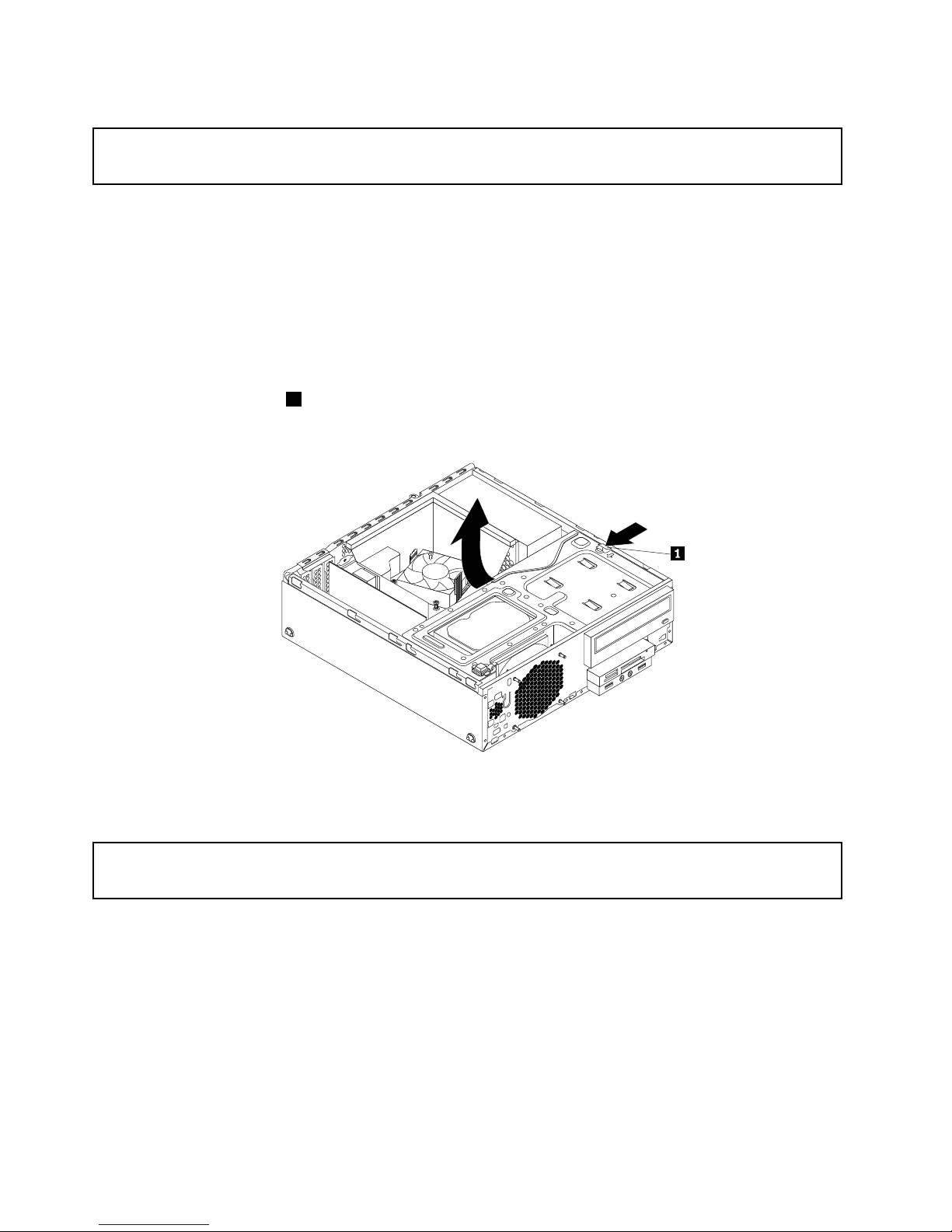
Accessingthesystemboardcomponentsanddrives
Attention:
Donotopenyourcomputerorattemptanyrepairbeforereadingandunderstandingthe“Importantsafetyinformation”
onpagev
.
Thissectionprovidesinstructionsonhowtoaccessthesystemboardcomponentsanddrives.
Toaccessthesystemboardcomponentsanddrives,dothefollowing:
1.Removeallmediafromthedrivesandturnoffallattacheddevicesandthecomputer.Then,disconnect
allpowercordsfromelectricaloutletsanddisconnectallcablesthatareconnectedtothecomputer.
2.Removethecomputercover.See“Removingthecomputercover”onpage36.
3.Removethefrontbezel.See“Removingandreinstallingthefrontbezel”onpage36.
4.Removetheheatsinkfanduct.See“Replacingtheheatsinkandfanassembly”onpage65.
5.Presstheretainingclip1inthedirectionasshownandpivotthedrivebayassemblyupwardatthe
sametime.
Figure15.Pivotingthedrivebayassemblyupward
InstallingorreplacingaPCIcard
Attention:
Donotopenyourcomputerorattemptanyrepairbeforereadingandunderstandingthe“Importantsafetyinformation”
onpagev.
ThissectionprovidesinstructionsonhowtoinstallorreplaceaPCIcard.YourcomputerhasvariousPCI
cardslots.Formoreinformation,see“Features”onpage1.
ToinstallorreplaceaPCIcard,dothefollowing:
1.Removeallmediafromthedrivesandturnoffallattacheddevicesandthecomputer.Then,disconnect
allpowercordsfromelectricaloutletsanddisconnectallcablesthatareconnectedtothecomputer.
2.Removethecomputercover.See“Removingthecomputercover”onpage36.
3.Removethefrontbezel.See“Removingandreinstallingthefrontbezel”onpage36.
4.RotatethePCIcardretainertotheopenposition.Dependingonwhetheryouareinstallingorreplacing
aPCIcard,dooneofthefollowing:
38ThinkCentreM83,M93/pUserGuide
Page 51
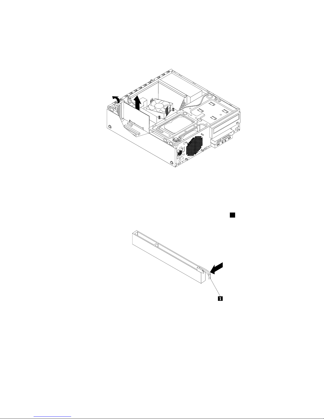
•IfyouareinstallingaPCIcard,removetheappropriatemetalslotcover.
•IfyouarereplacinganoldPCIcard,grasptheoldcardthatiscurrentlyinstalledandgentlypullit
outoftheslot.
Figure16.RemovingaPCIcard
Notes:
a.Thecardtstightlyintothecardslot.Ifnecessary,alternatemovingeachsideofthecardasmall
andequalamountuntilthecardisremovedfromtheslot.
b.Ifthecardisheldinplacebyaretaininglatch,presstheretaininglatch1asshowntodisengage
thelatch.Graspthecardandgentlypullitoutoftheslot.
5.RemovethenewPCIcardfromitsstatic-protectivepackage.
Chapter5.Installingorreplacinghardware39
Page 52
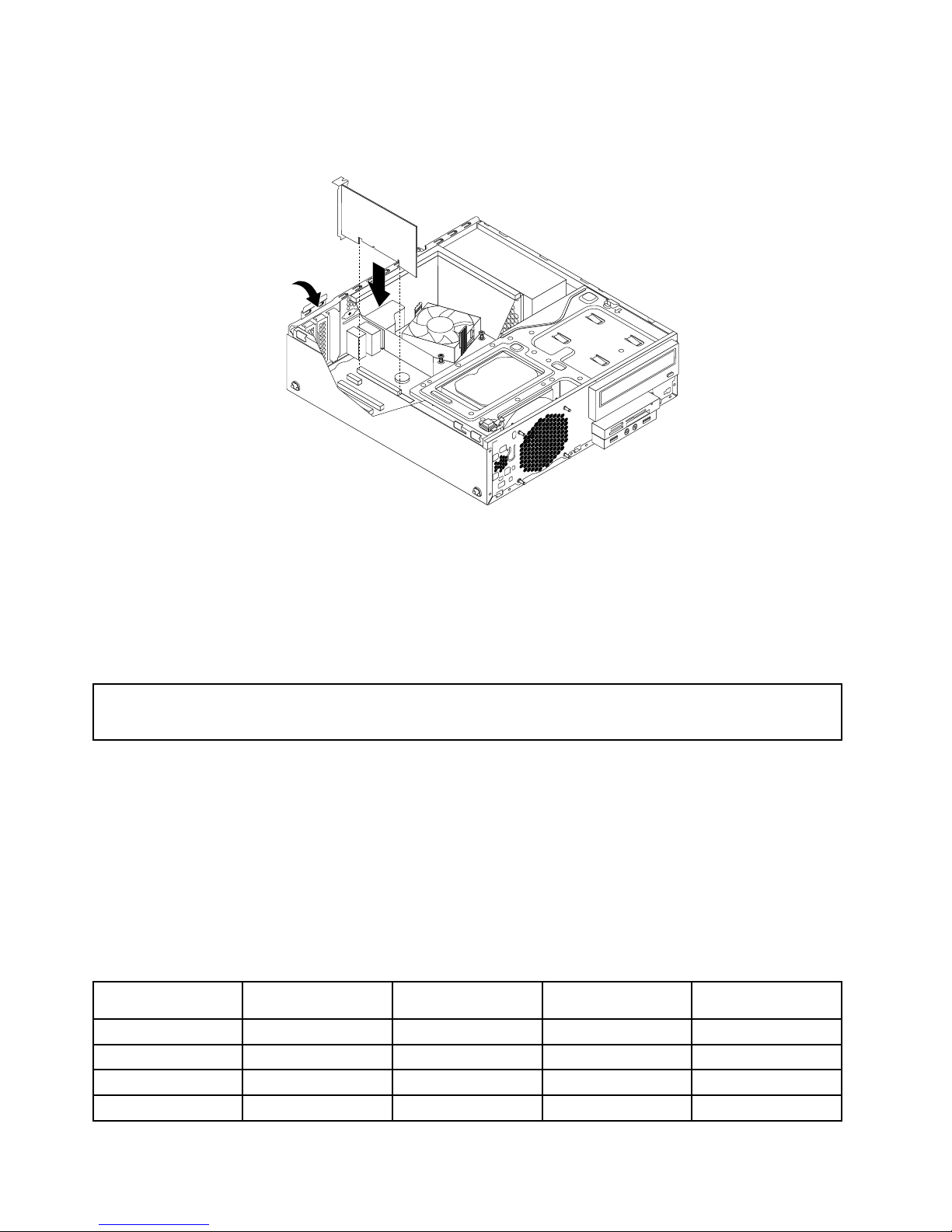
6.Installthenewcardintotheappropriatecardslotonthesystemboardandrotatethecardretainertothe
closedposition.See“Locatingpartsonthesystemboard”onpage14.
Figure17.InstallingaPCIcard
Whattodonext:
•Toworkwithanotherpieceofhardware,gototheappropriatesection.
•Tocompletetheinstallationorreplacement,goto“Completingthepartsreplacement”onpage103.
Installingorreplacingamemorymodule
Attention:
Donotopenyourcomputerorattemptanyrepairbeforereadingandunderstandingthe“Importantsafetyinformation”
onpagev.
Thissectionprovidesinstructionsonhowtoinstallorreplaceamemorymodule.
YourcomputerhasfourmemoryslotsforinstallingorreplacingDDR3UDIMMsthatprovideuptoa
maximumof32GBsystemmemory.Wheninstallingorreplacingamemorymodule,use2GB,4GB,or8
GBDDR3UDIMMsinanycombinationuptoamaximumof32GB.
Thefollowingtableprovidesinformationaboutthememorymoduleinstallationrulesthatyoushould
considerwheninstallingorremovingamemorymodule.The“X”markindicatesthememoryslotsintowhich
thememorymodulesshouldbeinstalledindifferentsituations.Thenumbers1,2,3,and4indicatethe
installationsequence.T olocatethememorymoduleslots,see“Locatingpartsonthesystemboard”
onpage14.
UDIMMDIMM1DIMM2DIMM3
DIMM4
OneUDIMM
X
TwoUDIMMsX,1X,2
ThreeUDIMMsX,3X,1X,2
FourUDIMMsX,3X,2X,4X,2
40ThinkCentreM83,M93/pUserGuide
Page 53
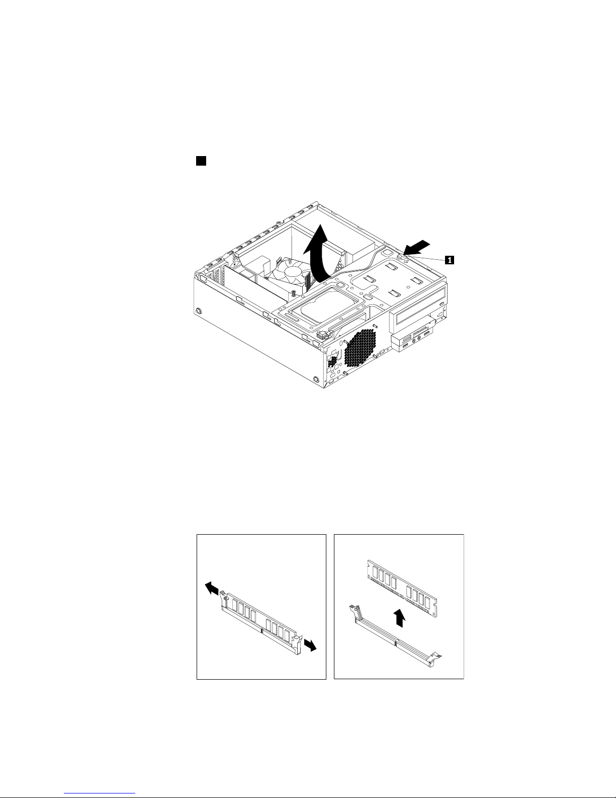
Toinstallorreplaceamemorymodule,dothefollowing:
1.Removeallmediafromthedrivesandturnoffallattacheddevicesandthecomputer.Then,disconnect
allpowercordsfromelectricaloutletsanddisconnectallcablesthatareconnectedtothecomputer.
2.Removethecomputercover.See“Removingthecomputercover”onpage36.
3.Removethefrontbezel.See“Removingandreinstallingthefrontbezel”onpage36
4.Locatethememoryslots.See“Locatingpartsonthesystemboard”onpage14.
5.Presstheretainingclip1inthedirectionasshownandpivotthedrivebayassemblyupwardatthe
sametime.
Figure18.Pivotingthedrivebayassemblyupward
6.Removetheheatsinkfanduct.See“Replacingtheheatsinkandfanassembly”onpage65.
7.Dependingonyourcomputermodel,youmightneedtoremovethePCIExpressx16graphicscardfor
easieraccesstothememoryslots.See“InstallingorreplacingaPCIcard”onpage38.
8.Dependingonwhetheryouareinstallingorreplacingamemorymodule,dooneofthefollowing:
•Ifyouarereplacinganoldmemorymodule,opentheretainingclipsandgentlypullthememory
moduleoutofthememoryslot.
Figure19.Removingamemorymodule
Chapter5.Installingorreplacinghardware41
Page 54
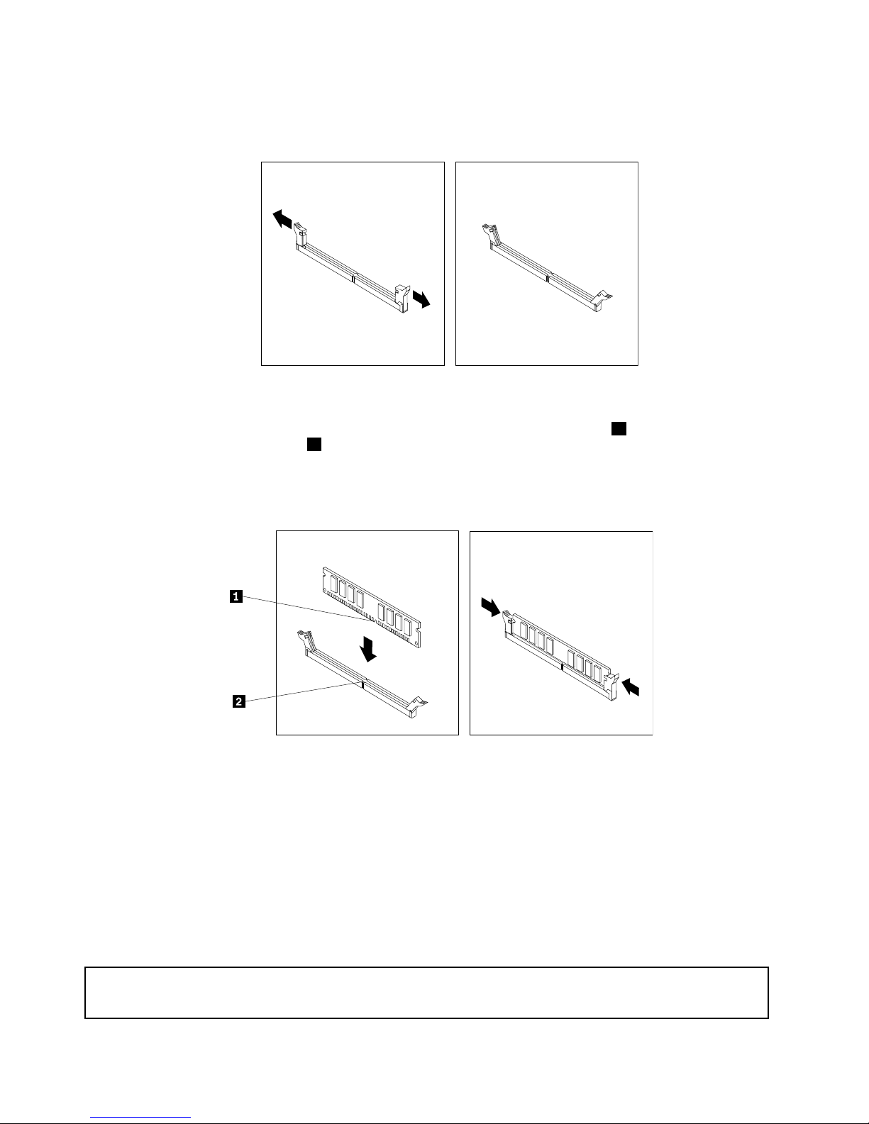
•Ifyouareinstallingamemorymodule,opentheretainingclipsofthememoryslotintowhichyou
wanttoinstallthememorymodule.
Figure20.Openingtheretainingclips
9.Positionthenewmemorymoduleoverthememoryslot.Ensurethatthenotch1onthenewmemory
moduleisalignedwiththekey2intheslot.Then,pushthenewmemorymodulestraightdownintothe
slotuntiltheretainingclipsfullyclose.
Note:Ensurethatthememorymoduleisseatedsecurelyandcannotbemovedeasily.
Figure21.Installingamemorymodule
10.ReinstallthePCIExpressx16graphicscardifyouhadremovedit.See“InstallingorreplacingaPCI
card”onpage38.
11.Reinstalltheheatsinkfanduct.See“Replacingtheheatsinkandfanassembly”onpage65.
Whattodonext:
•Toworkwithanotherpieceofhardware,gototheappropriatesection.
•Tocompletetheinstallationorreplacement,goto“Completingthepartsreplacement”onpage103.
Replacingtheopticaldrive
Attention:
Donotopenyourcomputerorattemptanyrepairbeforereadingandunderstandingthe“Importantsafetyinformation”
onpagev.
42ThinkCentreM83,M93/pUserGuide
Page 55
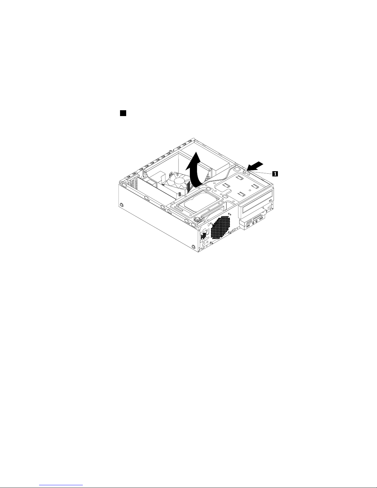
Thissectionprovidesinstructionsonhowtoreplacetheopticaldrive.
Toreplacetheopticaldrive,dothefollowing:
1.Removeallmediafromthedrivesandturnoffallattacheddevicesandthecomputer.Then,disconnect
allpowercordsfromelectricaloutletsanddisconnectallcablesthatareconnectedtothecomputer.
2.Removethecomputercover.See“Removingthecomputercover”onpage36.
3.Removethefrontbezel.See“Removingandreinstallingthefrontbezel”onpage36.
4.Locatetheopticaldrivebay.See“Locatinginternaldrives”onpage17.
5.Presstheretainingclip1inthedirectionasshownandpivotthedrivebayassemblyupwardatthe
sametime.
Figure22.Pivotingthedrivebayassemblyupward
6.Disconnectthesignalcableandthepowercablefromtherearoftheopticaldrive.
Chapter5.Installingorreplacinghardware43
Page 56
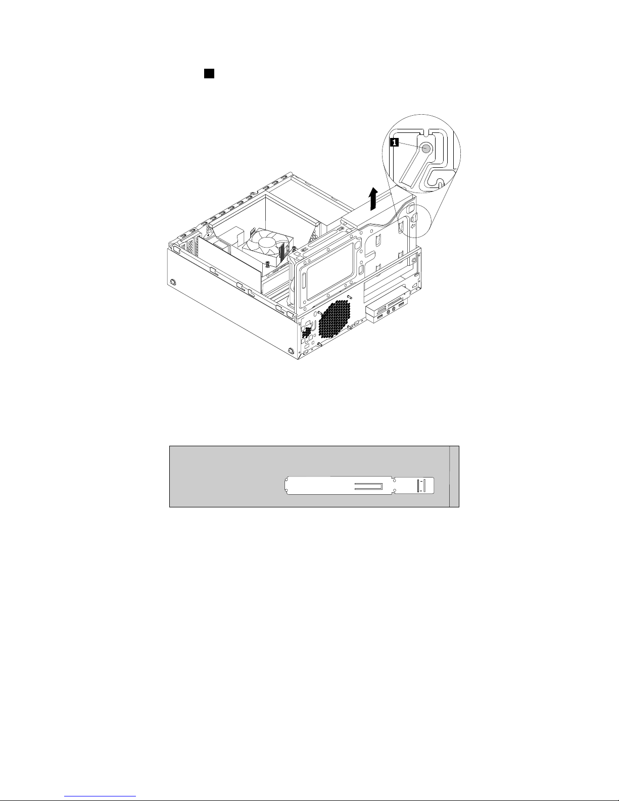
7.Presstheopticaldrivelock1ontherightsideofthedrivebayassemblyandslidetheopticaldriveout
oftherearofthebay.
Figure23.Removingtheopticaldrive
8.Removetheopticaldriveretainerfromthesideoftheoldopticaldriveandinstallitonthesideof
thenewopticaldrive.
Figure24.Installingtheopticaldriveretainer
44ThinkCentreM83,M93/pUserGuide
Page 57
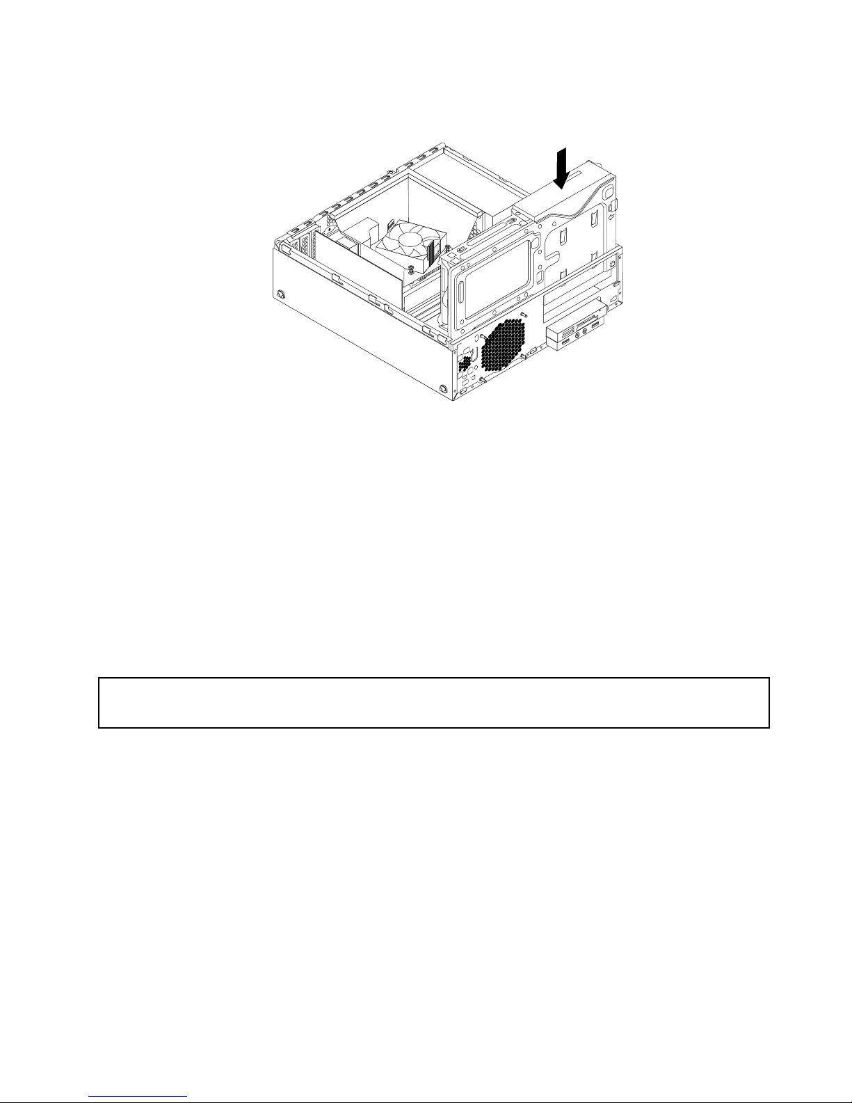
9.Slidethenewopticaldriveintothedrivebayuntilitsnapsintoposition.
Figure25.Installingtheopticaldrive
10.Connectthesignalcableandthepowercabletorearofthenewopticaldrive.
Whattodonext:
•Toworkwithanotherpieceofhardware,gototheappropriatesection.
•Tocompletetheinstallationorreplacement,goto“Completingthepartsreplacement”onpage103.
Installingorreplacingthecardreaderassembly
Thissectionprovidesinstructionsonhowtoinstallorreplacethecardreaderassembly.
Note:Thecardreaderassemblyisonlyavailableinsomemodels.
Installingthecardreaderassembly
Attention:
Donotopenyourcomputerorattemptanyrepairbeforereadingandunderstandingthe“Importantsafetyinformation”
onpagev.
Toinstallthecardreaderassembly,dothefollowing:
1.Removeallmediafromthedrivesandturnoffallattacheddevicesandthecomputer.Then,disconnect
allpowercordsfromelectricaloutletsanddisconnectallcablesthatareconnectedtothecomputer.
2.Removethecomputercover.See“Removingthecomputercover”onpage36.
3.Removethefrontbezel.See“Removingandreinstallingthefrontbezel”onpage36.
Chapter5.Installingorreplacinghardware45
Page 58
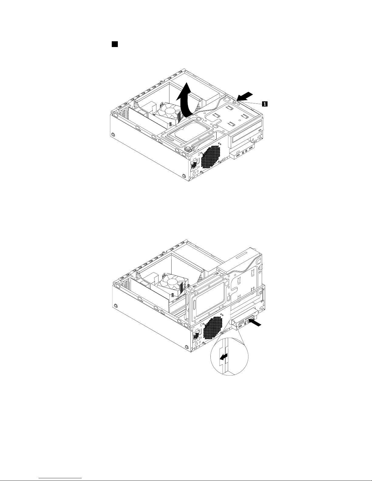
4.Presstheretainingclip1inthedirectionasshownandpivotthedrivebayassemblyupwardatthe
sametime.
Figure26.Pivotingthedrivebayassemblyupward
5.Installthenewcardreaderassemblyintothecardreaderdrivebayuntilitsnapsintoposition.Then,
pushthenewcardreaderassemblytotheleftuntilthescrewholeinthemetalbracketofthecard
readerassemblyisalignedwiththecorrespondingholeinthechassis.
Figure27.Installingthecardreaderassembly
46ThinkCentreM83,M93/pUserGuide
Page 59
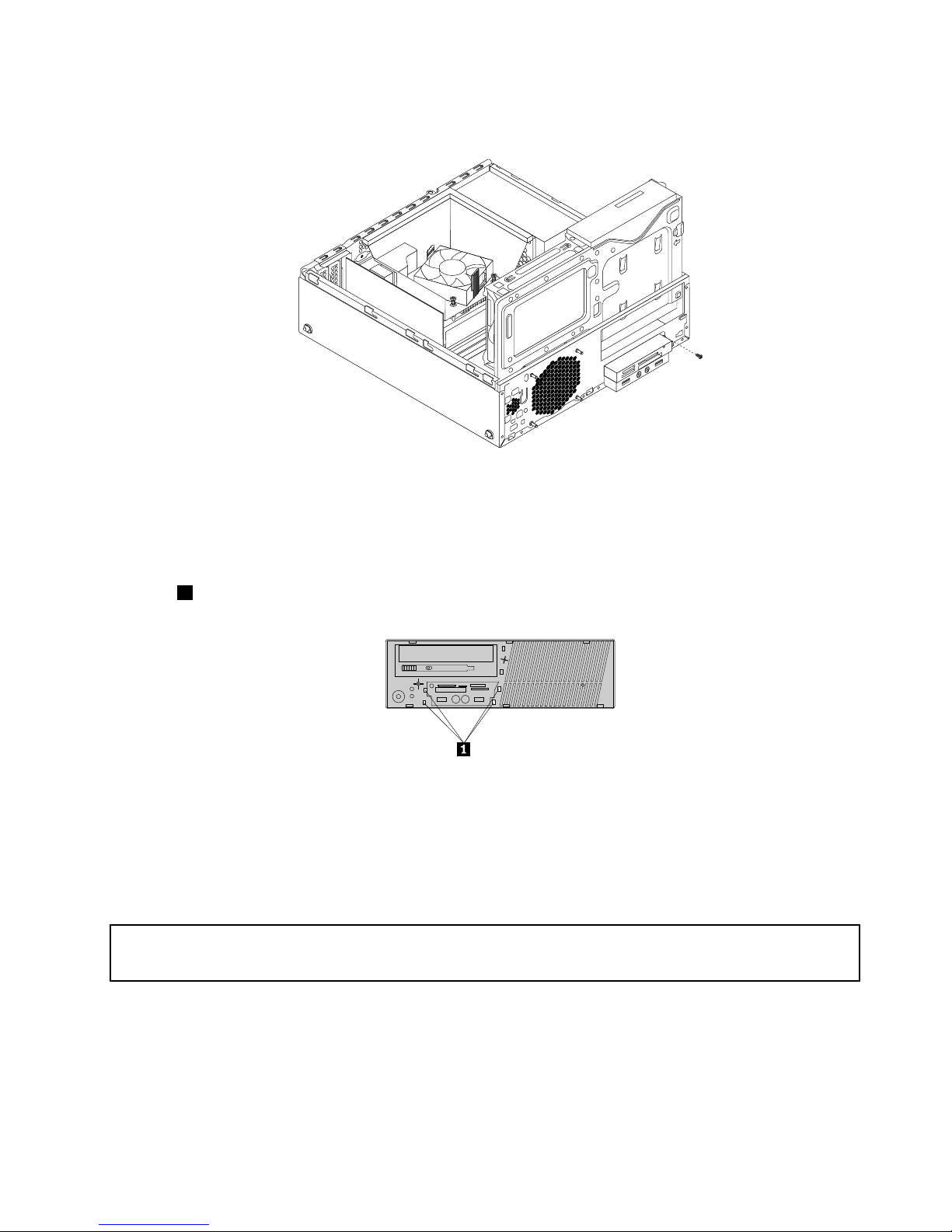
6.Installthescrewtosecurethecardreaderassemblytothechassis.
Figure28.Installingthescrewtosecurethecardreaderassembly
7.ConnectthecableofthenewcardreaderassemblytothefrontUSBconnector1onthesystemboard.
See“Locatingpartsonthesystemboard”onpage14
8.Beforeyoureinstallthefrontbezel,removetheprotectivepanelforthecardreaderassemblyandthe
frontaudioandUSBassemblyfromthefrontbezel.Toremovethisprotectivepanel,presstheretaining
clips1asshownandthencompletelydisengagetheprotectivepanel.
Figure29.Removingthecardreadercover
Whattodonext:
•Toworkwithanotherpieceofhardware,gototheappropriatesection.
•Tocompletetheinstallationorreplacement,goto“Completingthepartsreplacement”onpage103.
Replacingthecardreaderassembly
Attention:
Donotopenyourcomputerorattemptanyrepairbeforereadingandunderstandingthe“Importantsafetyinformation”
onpagev.
Toreplacethecardreaderassembly,dothefollowing:
1.Removeallmediafromthedrivesandturnoffallattacheddevicesandthecomputer.Then,disconnect
allpowercordsfromelectricaloutletsanddisconnectallcablesthatareconnectedtothecomputer.
2.Removethecomputercover.See“Removingthecomputercover”onpage36.
3.Removethefrontbezel.See“Removingandreinstallingthefrontbezel”onpage36.
Chapter5.Installingorreplacinghardware47
Page 60
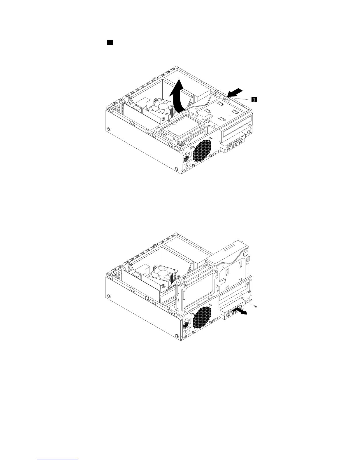
4.Presstheretainingclip1inthedirectionasshownandpivotthedrivebayassemblyupwardatthe
sametime.
Figure30.Pivotingthedrivebayassemblyupward
5.Disconnectthecardreadercablefromthesystemboard.
6.Removethescrewthatsecuresthecardreaderassembly.Pushthecardreaderassemblytotheright
andthenremoveitfromthechassis.
Figure31.Removingthecardreaderassembly
48ThinkCentreM83,M93/pUserGuide
Page 61
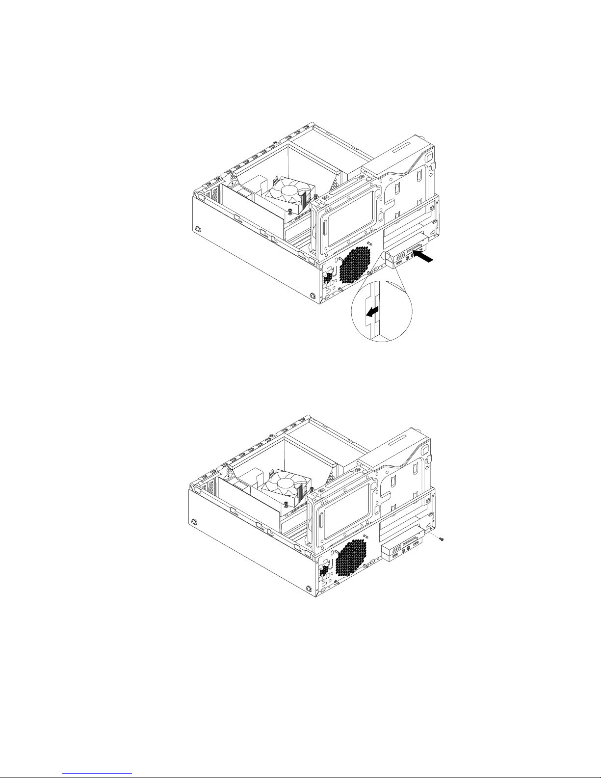
7.Installthenewcardreaderassemblyintothecardreaderdrivebayuntilitsnapsintoposition.Then,
pushthenewcardreaderassemblytotheleftuntilthescrewholeinthemetalbracketofthecard
readerassemblyisalignedwiththecorrespondingholeinthechassis.
Figure32.Installingthecardreaderassembly
8.Installthescrewtosecurethecardreaderassemblytothechassis.
Figure33.Installingthescrewtosecurethecardreaderassembly
9.ConnectthecableofthenewcardreaderassemblytothefrontUSBconnector1onthesystemboard.
See“Locatingpartsonthesystemboard”onpage14
Whattodonext:
•Toworkwithanotherpieceofhardware,gototheappropriatesection.
•Tocompletetheinstallationorreplacement,goto“Completingthepartsreplacement”onpage103.
Chapter5.Installingorreplacinghardware49
Page 62
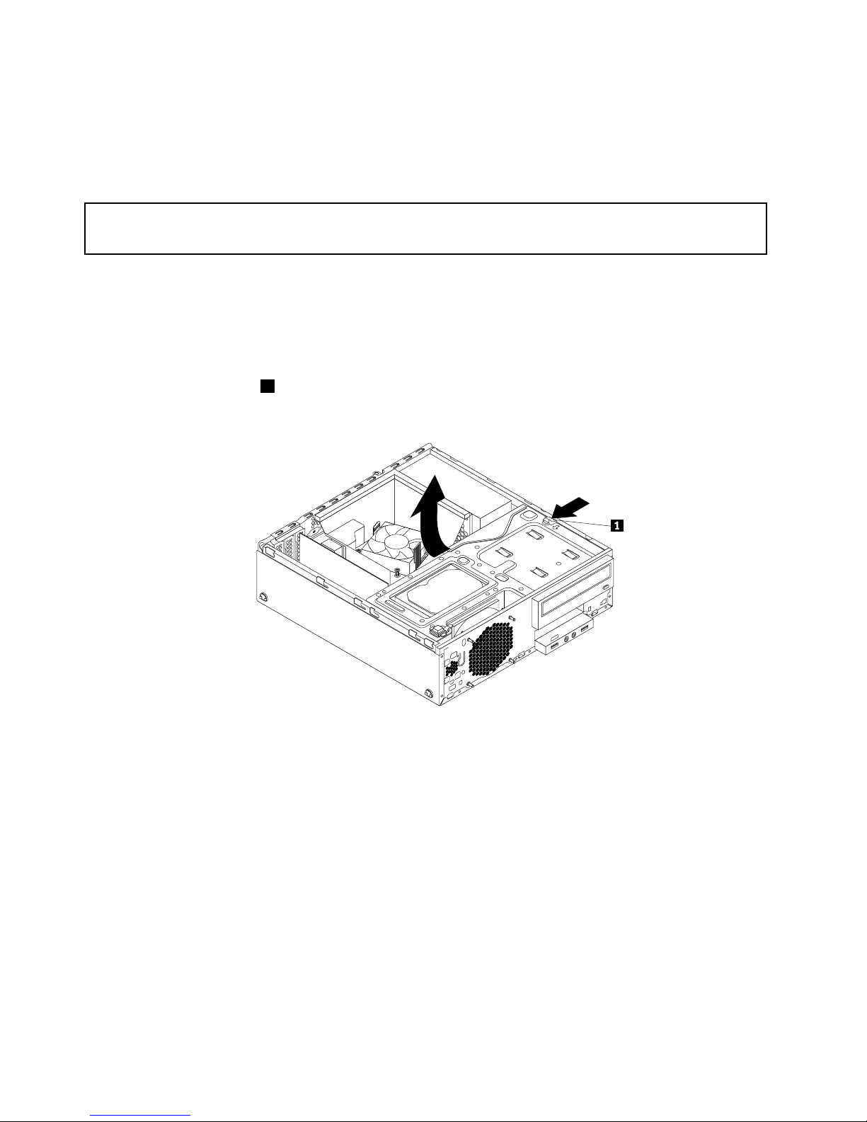
InstallingorreplacingthefrontUSBassembly
ThissectionprovidesinstructionsonhowtoinstallorreplacethefrontUSBassembly.
Note:ThefrontUSBassemblyisonlyavailableinsomemodels.
InstallingthefrontUSBassembly
Attention:
Donotopenyourcomputerorattemptanyrepairbeforereadingandunderstandingthe“Importantsafetyinformation”
onpagev.
ToinstallthefrontUSBassembly,dothefollowing:
1.Removeallmediafromthedrivesandturnoffallattacheddevicesandthecomputer.Then,disconnect
allpowercordsfromelectricaloutletsanddisconnectallcablesthatareconnectedtothecomputer.
2.Removethecomputercover.See“Removingthecomputercover”onpage36.
3.Removethefrontbezel.See“Removingandreinstallingthefrontbezel”onpage36.
4.Presstheretainingclip1inthedirectionasshownandpivotthedrivebayassemblyupwardatthe
sametime.
Figure34.Pivotingthedrivebayassemblyupward
5.ThepackageofthenewfrontUSBassemblycontainsafrontUSBboard,ametalbracket,andtwo
screws.InstallthefrontUSBboardintothemetalbracketandtheninstallthetwoscrewstosecure
thefrontUSBboardtothebracket.
50ThinkCentreM83,M93/pUserGuide
Page 63
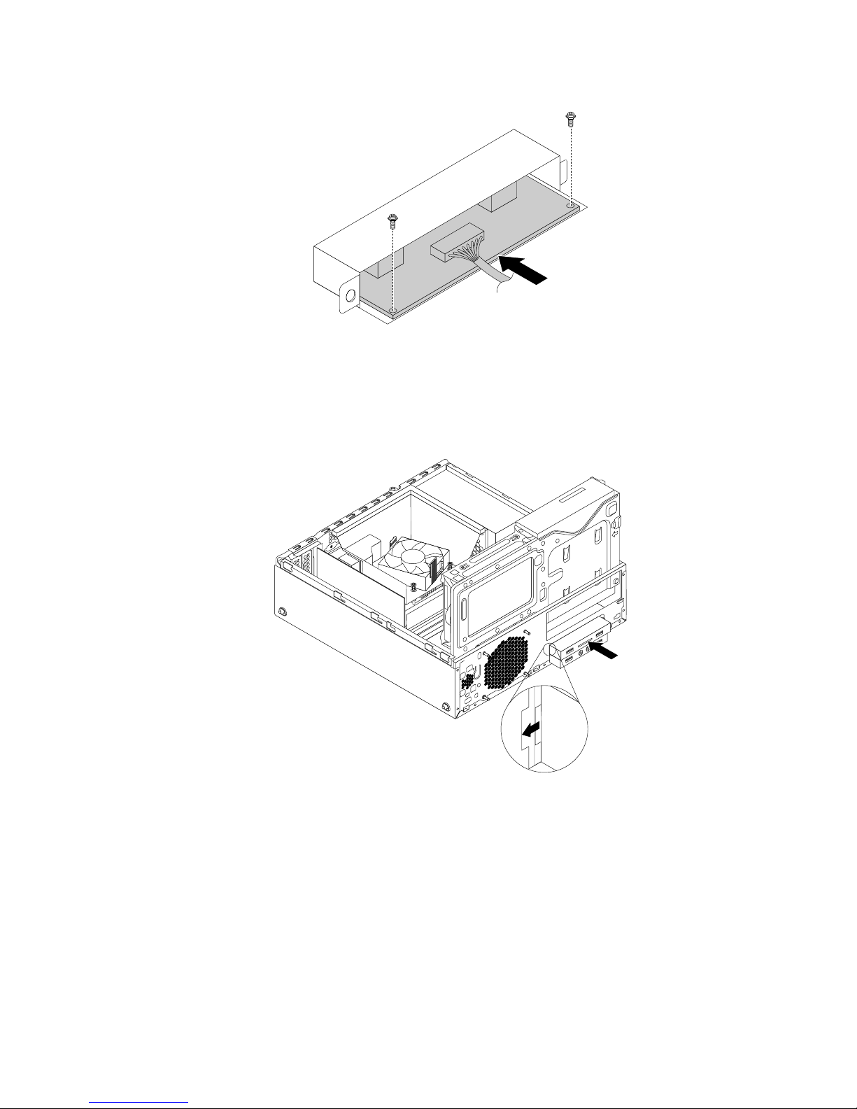
Figure35.AssemblingthefrontUSBassembly
6.InstallthenewfrontUSBassemblyintothecardreaderdrivebayuntilitsnapsintoposition.Then,
pushthenewfrontUSBassemblytotheleftuntilthescrewholeinthemetalbracketofthefrontUSB
assemblyisalignedwiththecorrespondingholeinthechassis.
Figure36.InstallingthefrontUSBassembly
Chapter5.Installingorreplacinghardware51
Page 64
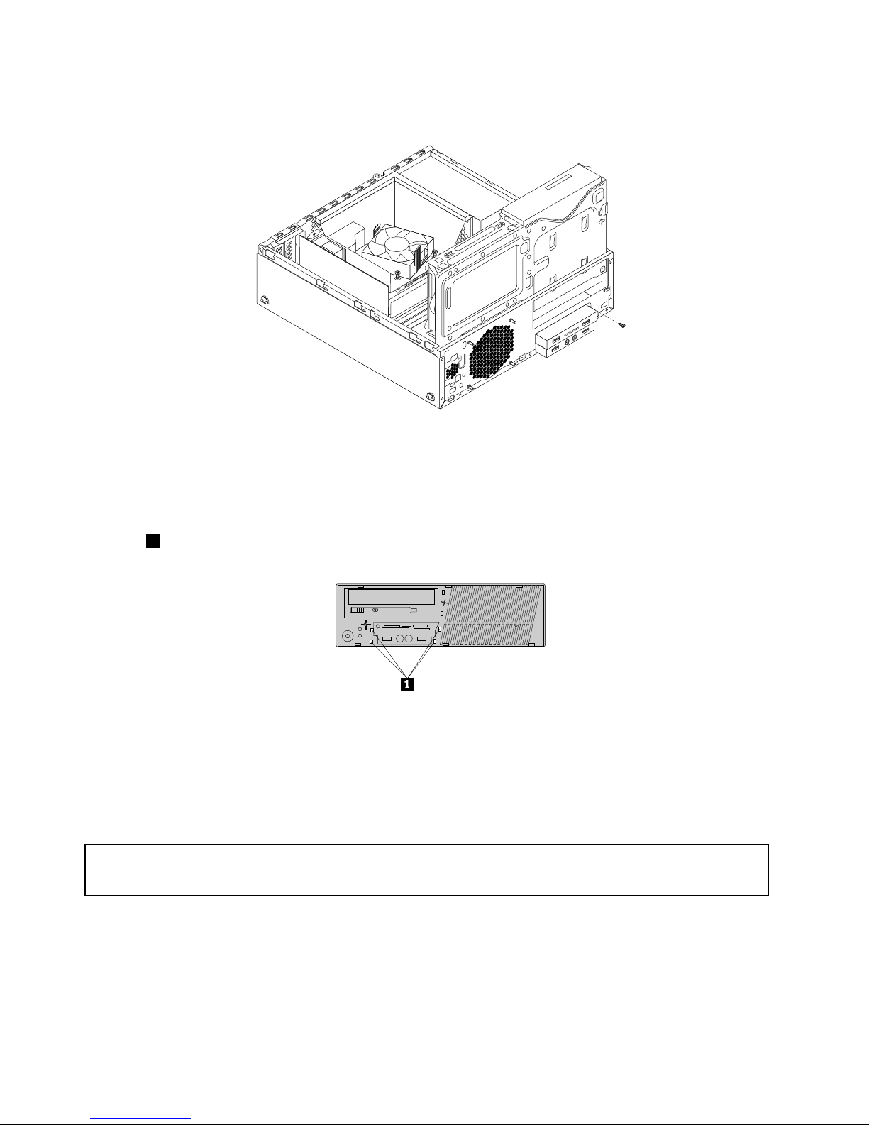
7.InstallthescrewtosecurethefrontUSBassemblytothechassis.
Figure37.InstallingthescrewtosecurethefrontUSBassembly
8.ConnectthecableofthenewfrontUSBassemblytothefrontUSBconnector1onthesystemboard.
See“Locatingpartsonthesystemboard”onpage14
9.Beforeyoureinstallthefrontbezel,removetheprotectivepanelforthecardreaderassemblyandthe
frontaudioandUSBassemblyfromthefrontbezel.Toremovethisprotectivepanel,presstheretaining
clips1asshownandthencompletelydisengagetheprotectivepanel.
Figure38.Removingtheprotectivepanel
Whattodonext:
•Toworkwithanotherpieceofhardware,gototheappropriatesection.
•Tocompletetheinstallationorreplacement,goto“Completingthepartsreplacement”onpage103.
ReplacingthefrontUSBassembly
Attention:
Donotopenyourcomputerorattemptanyrepairbeforereadingandunderstandingthe“Importantsafetyinformation”
onpagev.
ToreplacethefrontUSBassembly,dothefollowing:
1.Removeallmediafromthedrivesandturnoffallattacheddevicesandthecomputer.Then,disconnect
allpowercordsfromelectricaloutletsanddisconnectallcablesthatareconnectedtothecomputer.
2.Removethecomputercover.See“Removingthecomputercover”onpage36.
3.Removethefrontbezel.See“Removingandreinstallingthefrontbezel”onpage36.
52ThinkCentreM83,M93/pUserGuide
Page 65
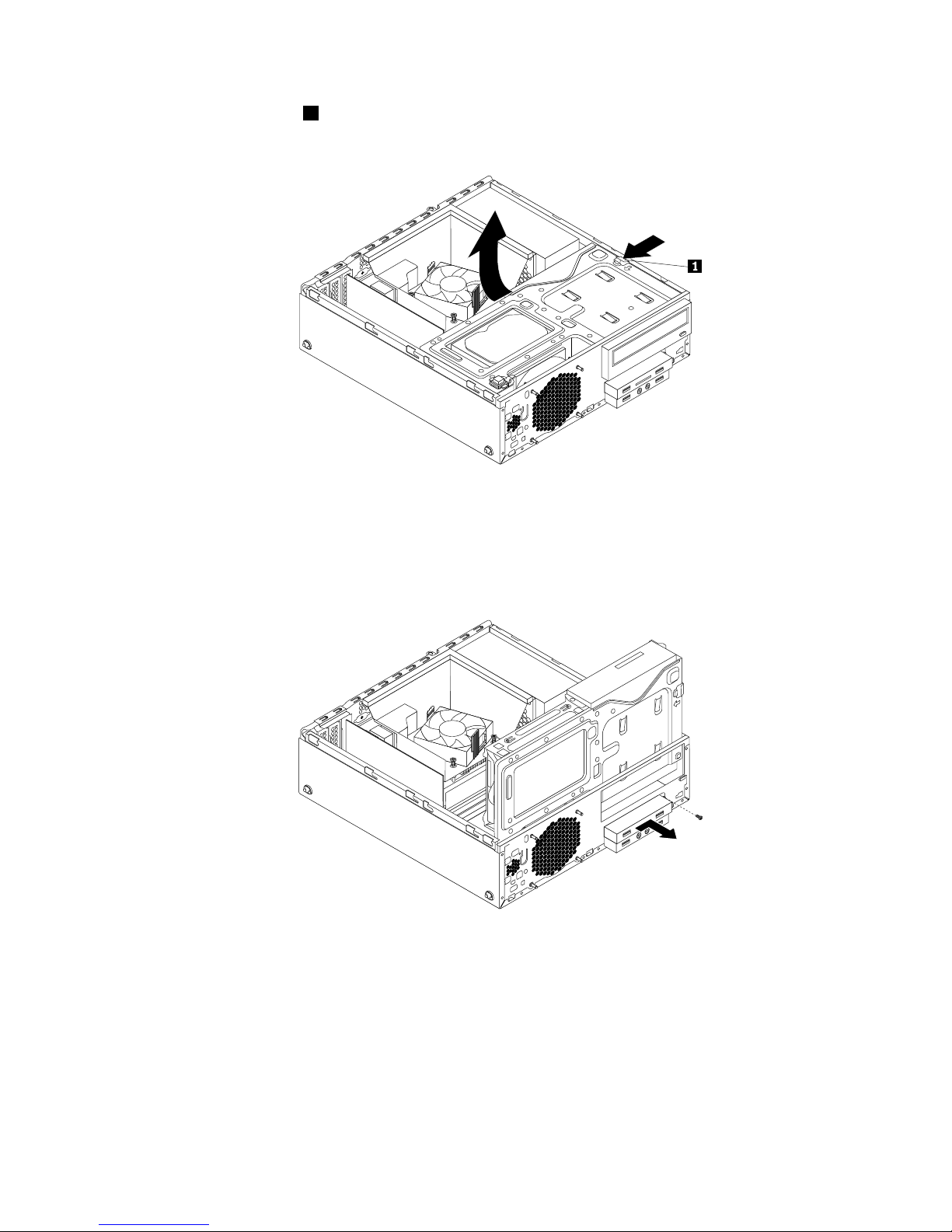
4.Presstheretainingclip1inthedirectionasshownandpivotthedrivebayassemblyupwardatthe
sametime.
Figure39.Pivotingthedrivebayassemblyupward
5.DisconnectthefrontUSBassemblycablefromthesystemboard.
6.RemovethescrewthatsecuresthefrontUSBassembly.PushthefrontUSBassemblytotheright
andthenremoveitfromthechassis.
Figure40.RemovingthefrontUSBassembly
Chapter5.Installingorreplacinghardware53
Page 66
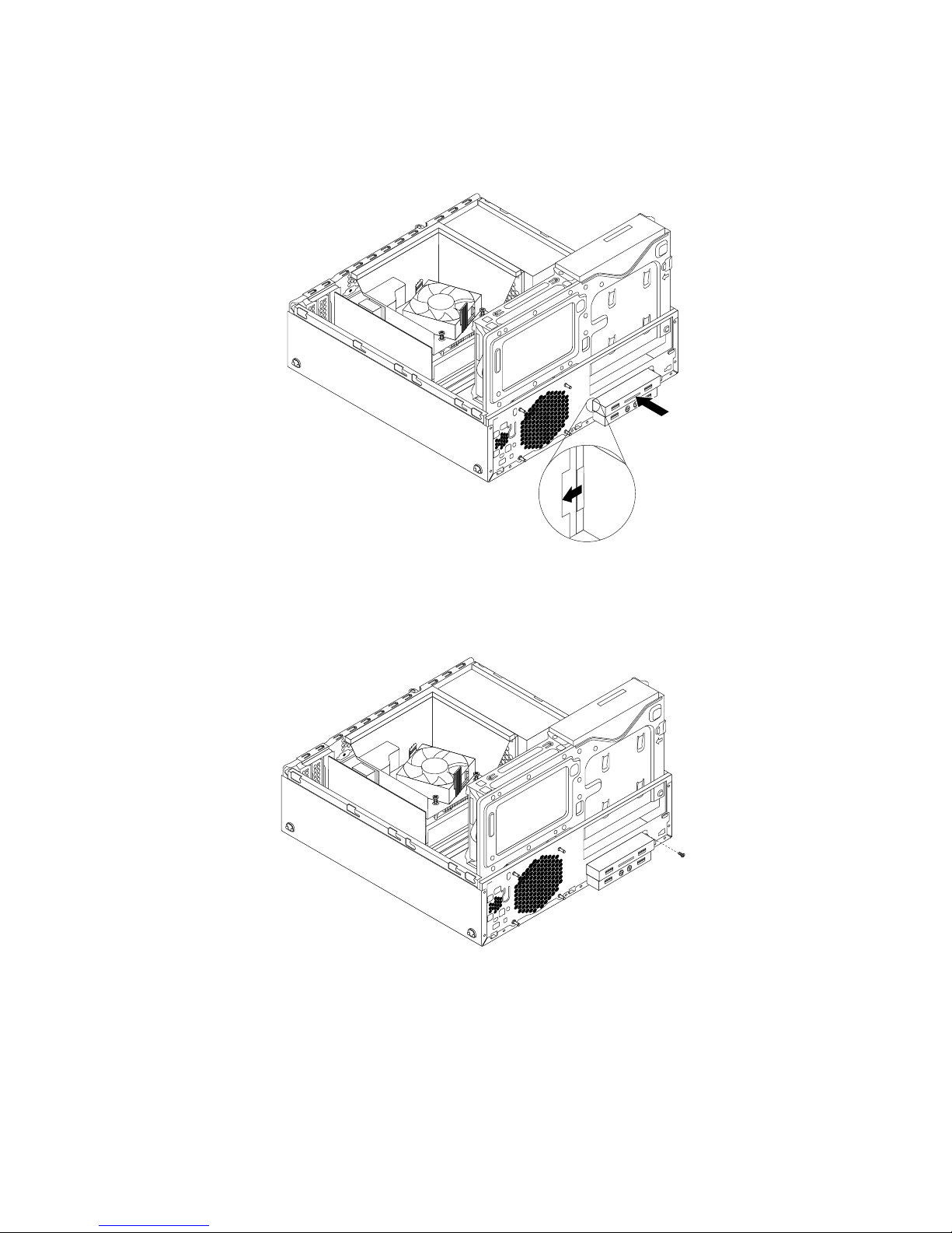
7.InstallthenewfrontUSBassemblyintothecardreaderdrivebayuntilitsnapsintoposition.Then,
pushthenewfrontUSBassemblytotheleftuntilthescrewholeinthemetalbracketofthefrontUSB
assemblyisalignedwiththecorrespondingholeinthechassis.
Figure41.InstallingthefrontUSBassembly
8.InstallthescrewtosecurethefrontUSBassemblytothechassis.
Figure42.InstallingthescrewtosecurethefrontUSBassembly
9.ConnectthecableofthenewfrontUSBassemblytothefrontUSBconnector1onthesystemboard.
See“Locatingpartsonthesystemboard”onpage14
Whattodonext:
•Toworkwithanotherpieceofhardware,gototheappropriatesection.
•Tocompletetheinstallationorreplacement,goto“Completingthepartsreplacement”onpage103.
54ThinkCentreM83,M93/pUserGuide
Page 67
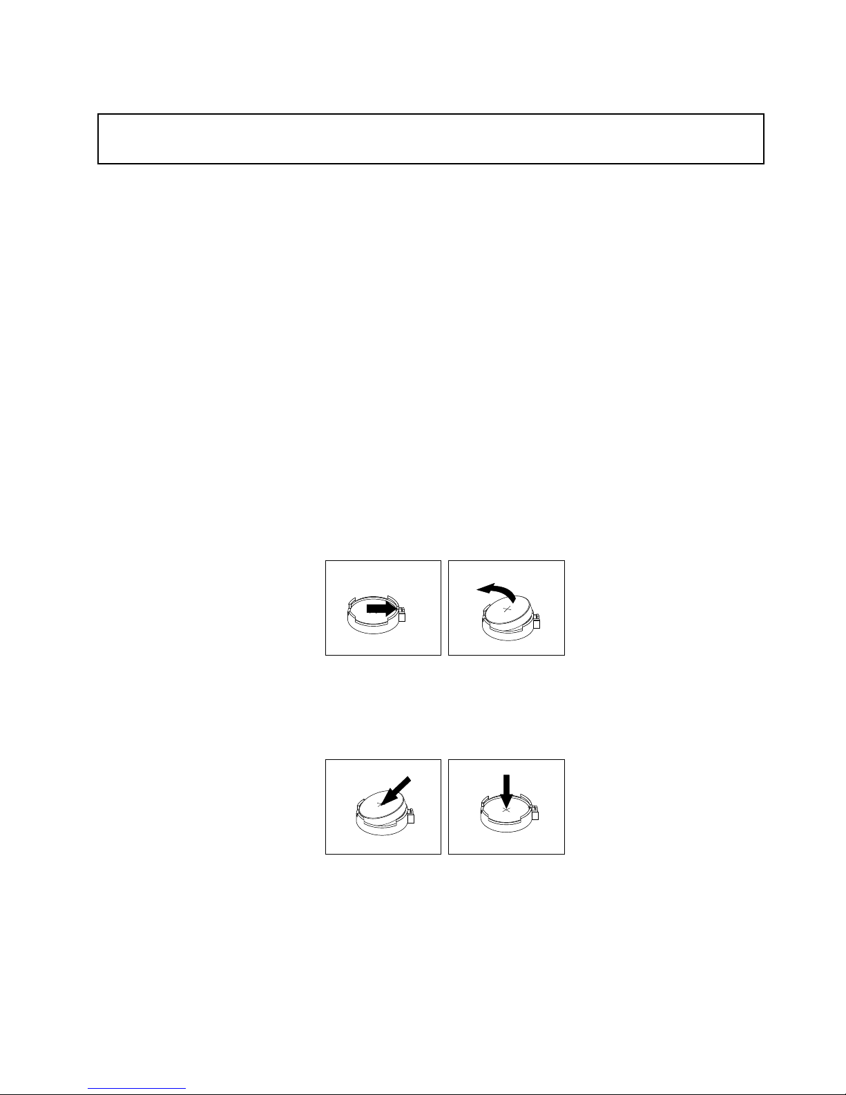
Replacingthebattery
Attention:
Donotopenyourcomputerorattemptanyrepairbeforereadingandunderstandingthe“Importantsafetyinformation”
onpagev
.
Yourcomputerhasaspecialtypeofmemorythatmaintainsthedate,time,andsettingsforbuilt-infeatures,
suchasparallel-portassignments(conguration).Abatterykeepsthisinformationactivewhenyouturn
offthecomputer.
Thebatterynormallyrequiresnochargingormaintenancethroughoutitslife;however,nobatterylasts
forever.Ifthebatteryfails,thedate,time,andcongurationinformation(includingpasswords)arelost.An
errormessageisdisplayedwhenyouturnonthecomputer.
Refertothe“Lithiumcoincellbatterynotice”intheSafety,Warranty,andSetupGuidethatcamewithyour
computerforinformationaboutreplacinganddisposingofthebattery.
Toreplacethebattery,dothefollowing:
1.Removeallmediafromthedrivesandturnoffallattacheddevicesandthecomputer.Then,disconnect
allpowercordsfromelectricaloutletsanddisconnectallcablesthatareconnectedtothecomputer.
2.Removethecomputercover.See“Removingthecomputercover”onpage36.
3.Removetheheatsinkfanduct.See“Replacingtheheatsinkandfanassembly”onpage65.
4.Dependingonyourcomputermodel,youmightneedtoremovethePCIExpressx16graphicscardfor
easieraccesstothebattery.See“InstallingorreplacingaPCIcard”onpage38.
5.Removetheoldbattery.
Figure43.Removingthebattery
6.Installanewbattery.
Figure44.Installingthebattery
7.ReinstallthePCIExpressx16graphicscardifyouhadremovedit.See“InstallingorreplacingaPCI
card”onpage38
.
8.Reinstalltheheatsinkfanduct.See“Replacingtheheatsinkandfanassembly”onpage65.
9.Reinstallthecomputercoverandreconnectthecables.See“Completingthepartsreplacement”on
page103
.
Chapter5.Installingorreplacinghardware55
Page 68
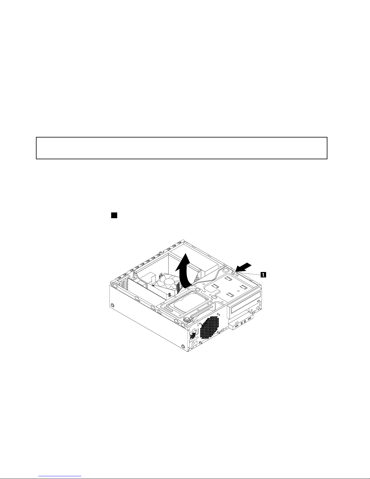
Note:Whenthecomputeristurnedonforthersttimeafterreplacingthebattery,anerrormessage
mightbedisplayed.Thisisnormalafterreplacingthebattery.
10.T urnonthecomputerandallattacheddevices.
11.UsetheSetupUtilityprogramtosetthedate,time,andanypasswords.SeeChapter7“Usingthe
SetupUtilityprogram”onpage115.
InstallingorreplacingthemSATAsolid-statedrive
ThissectionprovidesinstructionsonhowtoinstallorreplacethemSA TAsolid-statedrive.
Note:ThemSATAsolid-statedriveisonlyavailableinsomemodels.
InstallingthemSATAsolid-statedrive
Attention:
Donotopenyourcomputerorattemptanyrepairbeforereadingandunderstandingthe“Importantsafetyinformation”
onpagev.
ToinstallthemSATAsolid-statedrive,dothefollowing:
1.Removeallmediafromthedrivesandturnoffallattacheddevicesandthecomputer.Then,disconnect
allpowercordsfromelectricaloutletsanddisconnectallcablesthatareconnectedtothecomputer.
2.Removethecomputercover.See“Removingthecomputercover”onpage36.
3.Removethefrontbezel.See“Removingandreinstallingthefrontbezel”onpage36.
4.Presstheretainingclip1inthedirectionasshownandpivotthedrivebayassemblyupwardatthe
sametime.
Figure45.Pivotingthedrivebayassemblyupward
5.T akethenewmSATAsolid-statedriveandthestorageconverteroutofitsstatic-protectivepackage.
56ThinkCentreM83,M93/pUserGuide
Page 69
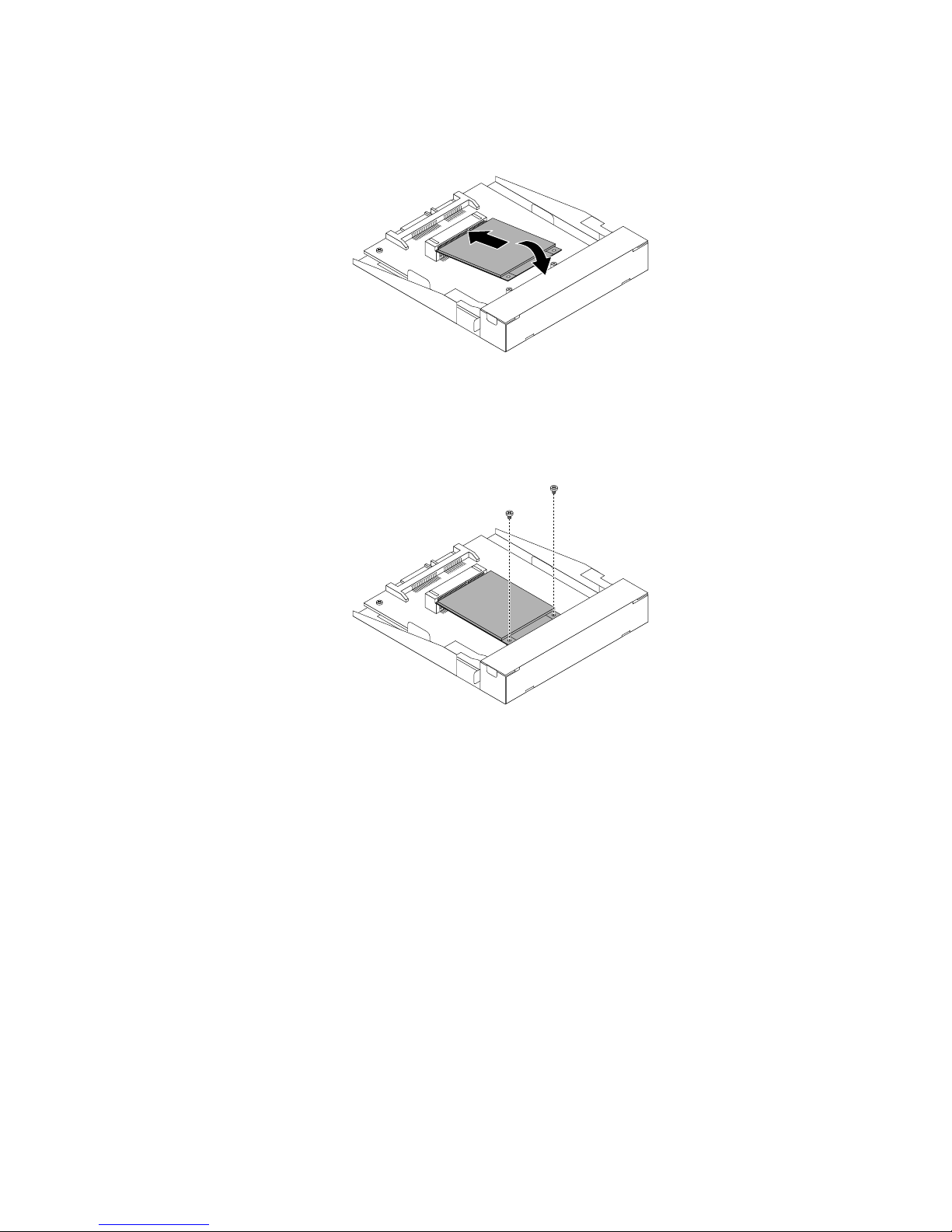
6.CarefullyinsertthemSATAsolid-statedriveintotheminiPCIExpressslotonthestorageconverteratan
angleofabout20degrees.Then,pressthemSATAsolid-statedrivedownward.
Figure46.InstallingthemSAT Asolid-statedriveintothestorageconverter
7.InstallthetwoscrewsthatcamewiththemSATAsolid-statedrivetosecurethedrivetothestorage
converter.
Figure47.InstallingthescrewstosecurethemSA TAsolid-statedrive
Chapter5.Installingorreplacinghardware57
Page 70

8.InstallthenewmSATAsolid-statedriveintothecardreaderdrivebayuntilitsnapsintoposition.Then,
pushthenewmSATAsolid-statedrivetotheleftuntilthescrewholeinthemetalbracketofthemSATA
solid-statedriveisalignedwiththecorrespondingholeinthechassis.
Figure48.InstallingthemSA TAsolid-statedriveintothechassis
9.Connectthesignalcableandthepowercabletotherearofthestorageconverter.
Whattodonext:
•Toworkwithanotherpieceofhardware,gototheappropriatesection.
•Tocompletetheinstallationorreplacement,goto“Completingthepartsreplacement”onpage103
.
ReplacingthemSATAsolid-statedrive
Attention:
Donotopenyourcomputerorattemptanyrepairbeforereadingandunderstandingthe“Importantsafetyinformation”
onpagev.
ToreplacethemSATAsolid-statedrive,dothefollowing:
1.Removeallmediafromthedrivesandturnoffallattacheddevicesandthecomputer.Then,disconnect
allpowercordsfromelectricaloutletsanddisconnectallcablesthatareconnectedtothecomputer.
2.Removethecomputercover.See“Removingthecomputercover”onpage36.
3.Removethefrontbezel.See“Removingandreinstallingthefrontbezel”onpage36.
58ThinkCentreM83,M93/pUserGuide
Page 71
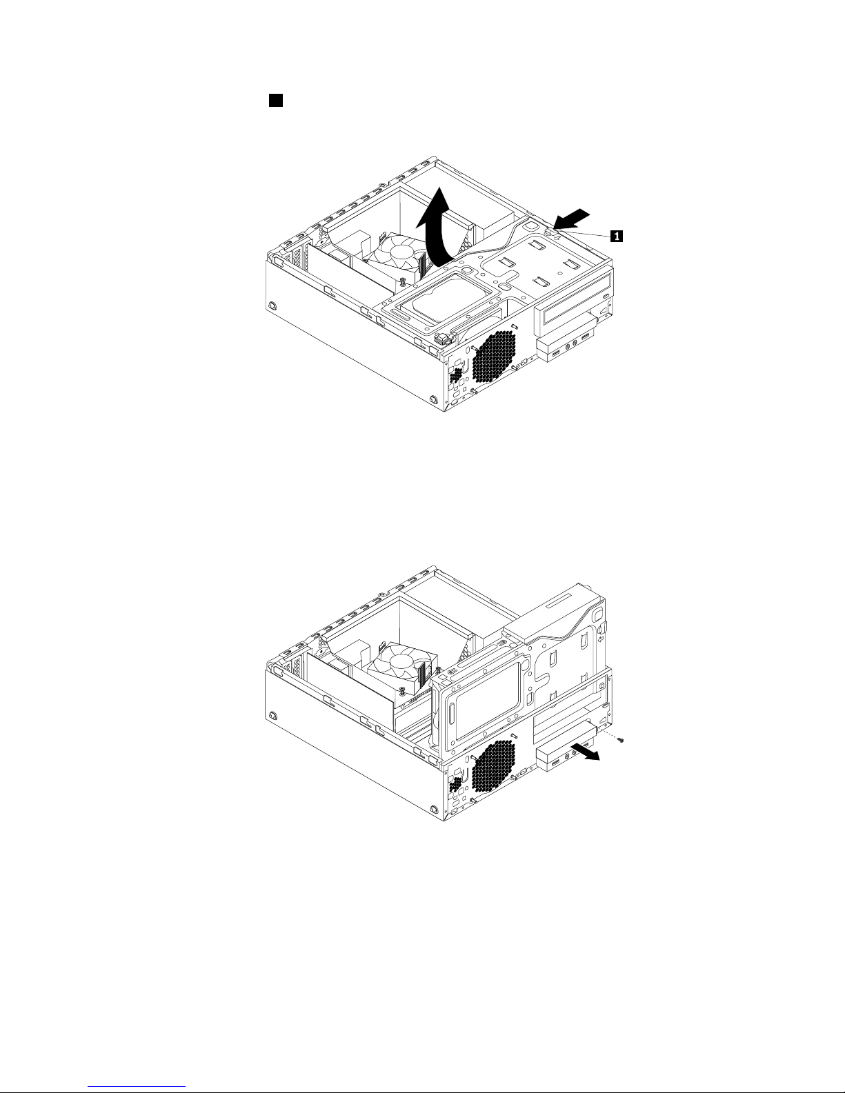
4.Presstheretainingclip1inthedirectionasshownandpivotthedrivebayassemblyupwardatthe
sametime.
Figure49.Pivotingthedrivebayassemblyupward
5.DisconnectthesignalcableandpowercablefromtherearofthemSATAsolid-statedrivestorage
converter.
6.RemovethescrewthatsecuresthemSATAsolid-statedrivestorageconverter.Then,slidethemSA TA
solid-statedrivestorageconverteroutofthecardreaderdrivebay.
Figure50.RemovingthemSA TAsolid-statedrivefromthechassis
Chapter5.Installingorreplacinghardware59
Page 72
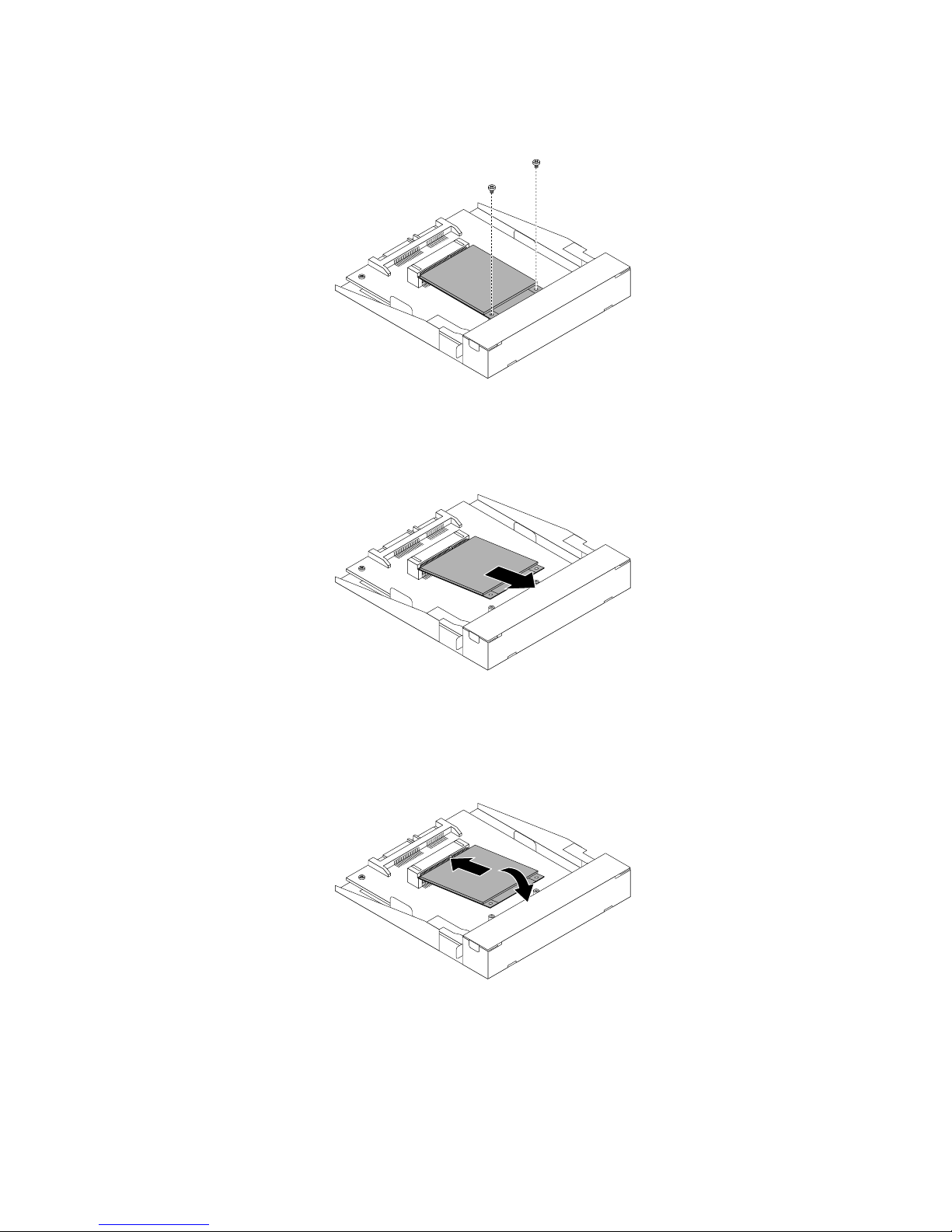
7.RemovethetwoscrewsthatsecurethemSATAsolid-statedrive.
Figure51.RemovingthescrewsthatsecurethemSA TAsolid-statedrive
8.PullthemSATAsolid-statedriveoutoftheminiPCIExpressslotonthestorageconverter.
Figure52.RemovingthemSAT Asolid-statedrivefromthestorageconverter
9.CarefullyinsertthemSATAsolid-statedriveintotheminiPCIExpressslotonthestorageconverteratan
angleofabout20degrees.Then,pressthemSATAsolid-statedrivedownward.
Figure53.InstallingthemSAT Asolid-statedriveintothestorageconverter
60ThinkCentreM83,M93/pUserGuide
Page 73
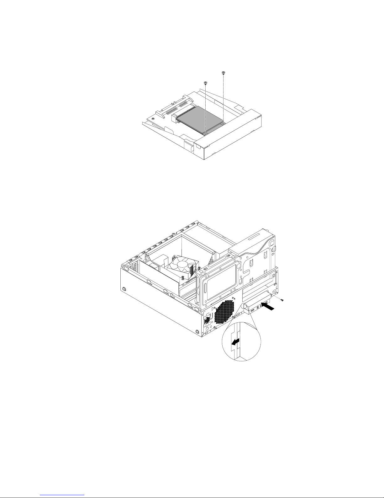
10.InstallthetwoscrewsthatcamewiththemSATAsolid-statedrivetosecurethedrivetothestorage
converter.
Figure54.InstallingthescrewstosecurethemSA TAsolid-statedrive
11.InstallthenewmSATAsolid-statedriveintothecardreaderdrivebayuntilitsnapsintoposition.Then,
pushthenewmSATAsolid-statedrivetotheleftuntilthescrewholeinthemetalbracketofthemSATA
solid-statedriveisalignedwiththecorrespondingholeinthechassis.
Figure55.InstallingthemSA TAsolid-statedriveintothechassis
12.Reconnectthesignalcableandthepowercabletotherearofthestorageconverter.
Whattodonext:
•Toworkwithanotherpieceofhardware,gototheappropriatesection.
•Tocompletetheinstallationorreplacement,goto“Completingthepartsreplacement”onpage103.
Chapter5.Installingorreplacinghardware61
Page 74
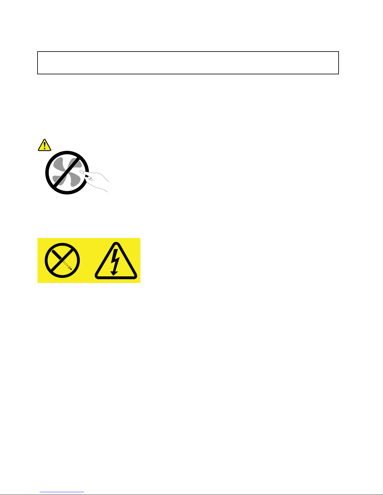
Replacingthepowersupplyassembly
Attention:
Donotopenyourcomputerorattemptanyrepairbeforereadingandunderstandingthe“Importantsafetyinformation”
onpagev
.
Thissectionprovidesinstructionsonhowtoreplacethepowersupplyassembly.
Althoughtherearenomovingpartsinyourcomputerafterthepowercordhasbeendisconnected,the
followingwarningsarerequiredforyoursafetyandproperUnderwritersLaboratories(UL)certication.
CAUTION:
Hazardousmovingparts.Keepngersandotherbodypartsaway.
CAUTION:
Neverremovethecoveronapowersupplyoranypartthathasthefollowinglabelattached.
Hazardousvoltage,current,andenergylevelsarepresentinsideanycomponentthathasthislabel
attached.Therearenoserviceablepartsinsidethesecomponents.Ifyoususpectaproblemwith
oneoftheseparts,contactaservicetechnician.
Toreplacethepowersupplyassembly,dothefollowing:
1.Removeallmediafromthedrivesandturnoffallattacheddevicesandthecomputer.Then,disconnect
allpowercordsfromelectricaloutletsanddisconnectallcablesthatareconnectedtothecomputer.
2.Removethecomputercover.See“Removingthecomputercover”onpage36.
3.Removethefrontbezel.See“Removingandreinstallingthefrontbezel”onpage36.
62ThinkCentreM83,M93/pUserGuide
Page 75
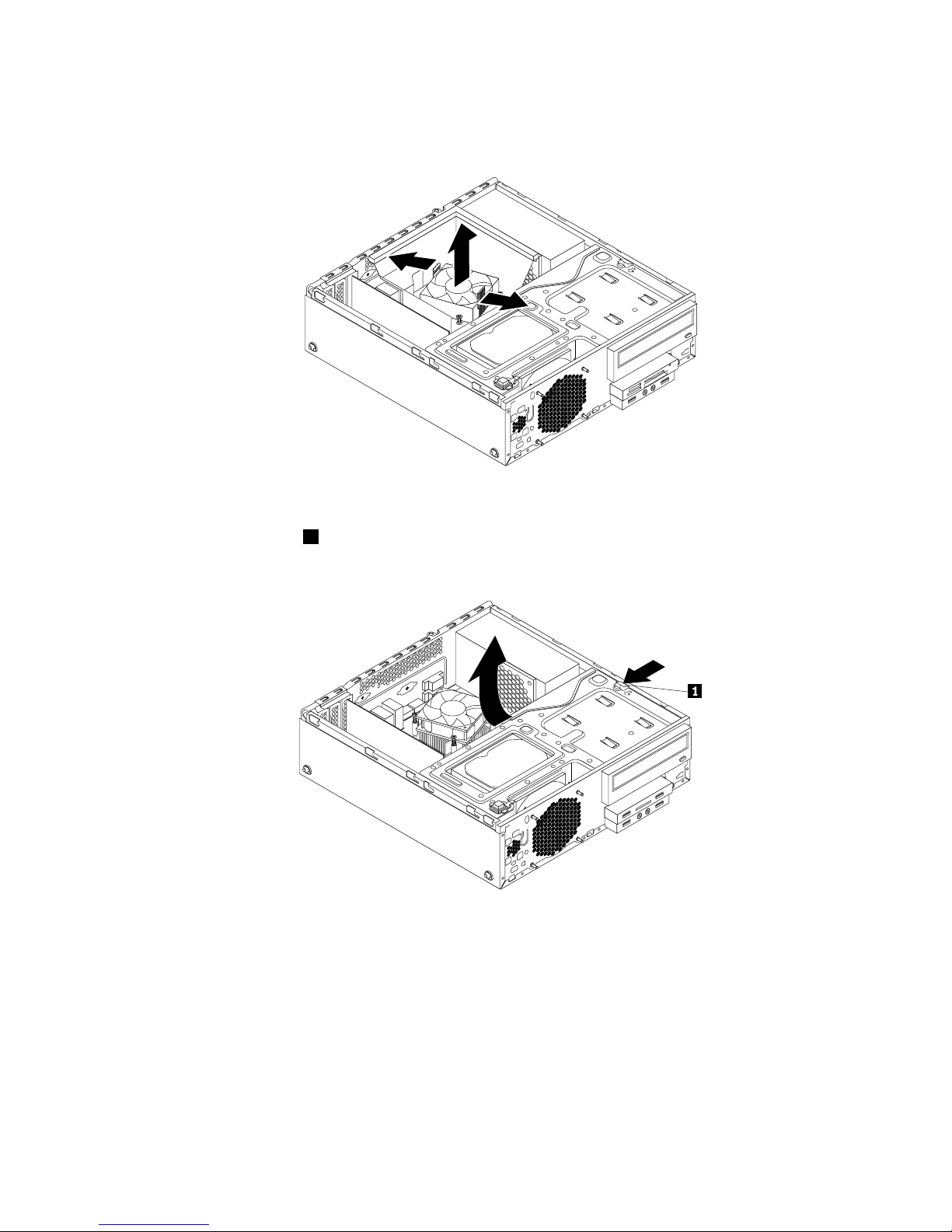
4.Gentlypivotthetwoplasticretainingclipsthatsecuretheheatsinkfanductoutward,andthenliftthe
heatsinkfanductoutofthechassis.
Figure56.Removingtheheatsinkfanduct
5.Presstheretainingclip1inthedirectionasshownandpivotthedrivebayassemblyupwardatthe
sametime.
Figure57.Pivotingthedrivebayassemblyupward
6.Recordthecableroutingandcableconnections.Then,disconnectthepowersupplyassemblycables
fromthesystemboardandalldrives.
7.Releasethepowersupplyassemblycablesfromanycableclipsortiesthatsecurethecablestothe
chassis.
Chapter5.Installingorreplacinghardware63
Page 76
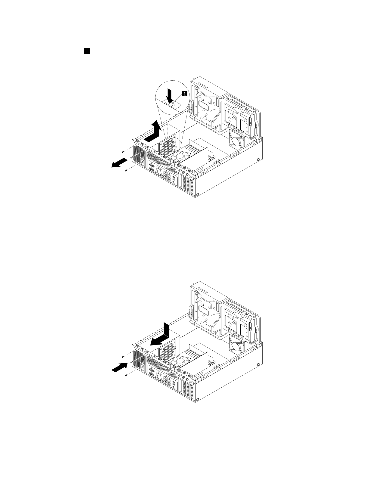
8.Attherearofthecomputer,removethethreescrewsthatsecurethepowersupplyassembly.Pressthe
retainingclip1downwardandslidethepowersupplyassemblytothefrontofthecomputer.Then,lift
thepowersupplyassemblyoutofthecomputer.
3
4
5
6 7 8
Figure58.Removingthepowersupplyassembly
9.Ensurethatthenewpowersupplyassemblyisthecorrectreplacement.
10.Installthenewpowersupplyassemblyintothechassissothatthescrewholesinthenewpowersupply
assemblyarealignedwiththecorrespondingholesintherearofthechassis.Then,installthethree
screwstosecurethenewpowersupplyassembly.
Note:UseonlyscrewsprovidedbyLenovo.
3
4
5
6 7 8
Figure59.Installingthepowersupplyassembly
64ThinkCentreM83,M93/pUserGuide
Page 77
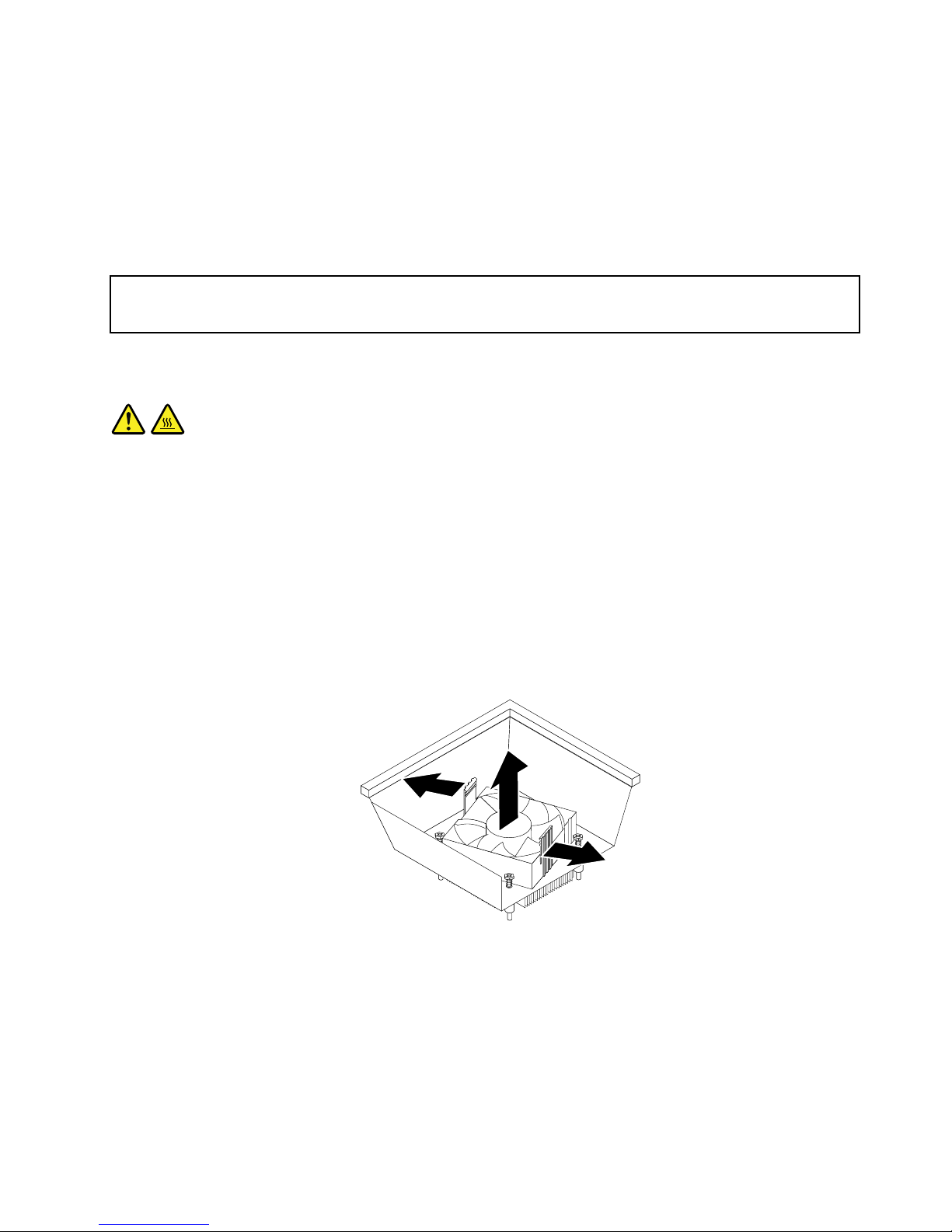
11.Connectthenewpowersupplyassemblycablestoalldrivesandthesystemboard.See“Locating
partsonthesystemboard”onpage14.
Whattodonext:
•Toworkwithanotherpieceofhardware,gototheappropriatesection.
•Tocompletetheinstallationorreplacement,goto“Completingthepartsreplacement”onpage103.
Replacingtheheatsinkandfanassembly
Attention:
Donotopenyourcomputerorattemptanyrepairbeforereadingandunderstandingthe“Importantsafetyinformation”
onpagev.
Thissectionprovidesinstructionsonhowtoreplacetheheatsinkandfanassembly.
CAUTION:
Theheatsinkandfanassemblymightbeveryhot.T urnoffthecomputerandwaitthreetove
minutestoletthecomputercoolbeforeremovingthecomputercover.
Toreplacetheheatsinkandfanassembly,dothefollowing:
1.Removeallmediafromthedrivesandturnoffallattacheddevicesandthecomputer.Then,disconnect
allpowercordsfromelectricaloutletsanddisconnectallcablesthatareconnectedtothecomputer.
2.Removethecomputercover.See“Removingthecomputercover”onpage36.
3.Removethefrontbezel.See“Removingandreinstallingthefrontbezel”onpage36.
4.Locatetheheatsinkandfanassembly.See“Locatingcomponents”onpage14
5.Pivotthetwoplasticretainingclipsthatsecuretheheatsinkfanductoutward.Then,removetheheat
sinkfanductfromthefailingheatsinkandfanassembly.
Figure60.Removingtheheatsinkfanduct
6.Disconnectthecableoftheheatsinkandfanassemblyfromthesystemboard.
Chapter5.Installingorreplacinghardware65
Page 78
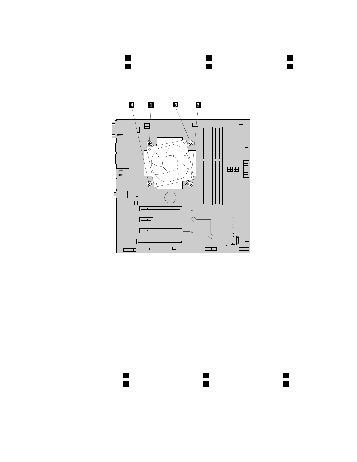
7.Followthefollowingsequencetoremovethefourscrewsthatsecuretheheatsinkandfanassembly
tothesystemboard:
a.Partiallyremovethescrew1,thenfullyremovethescrew2,thenfullyremovethescrew1.
b.Partiallyremovethescrew3,thenfullyremovethescrew4,thenfullyremovethescrew3.
Note:Carefullyremovethefourscrewsfromthesystemboardtoavoidanypossibledamagetothe
systemboard.Thefourscrewscannotberemovedfromtheheatsinkandfanassembly.
Figure61.Removingtheheatsinkandfanassembly
8.Lifttheheatsinkandfanassemblyoffthesystemboard.
Notes:
•Youmighthavetogentlytwisttheheatsinkandfanassemblytofreeitfromthemicroprocessor.
•Donottouchthethermalgreasewhilehandlingtheheatsinkandfanassembly.
9.Positionthenewheatsinkandfanassemblyonthesystemboardsothatthefourscrewsonthenew
heatsinkandfanassemblyarealignedwiththecorrespondingholesonthesystemboard.Ensurethat
thecableofthenewheatsinkandfanassemblyfacestowardthemicroprocessorfanconnector
onthesystemboard.
10.Followthefollowingsequencetoinstallthefourscrewstosecurethenewheatsinkandfanassembly.
Donotover-tightenthescrews.
Notes:
a.Partiallytightenthescrew1,thenfullytightenthescrew2,thenfullytightenthescrew1.
b.Partiallytightenthescrew3,thenfullytightenthescrew4,thenfullytightenthescrew3.
66ThinkCentreM83,M93/pUserGuide
Page 79
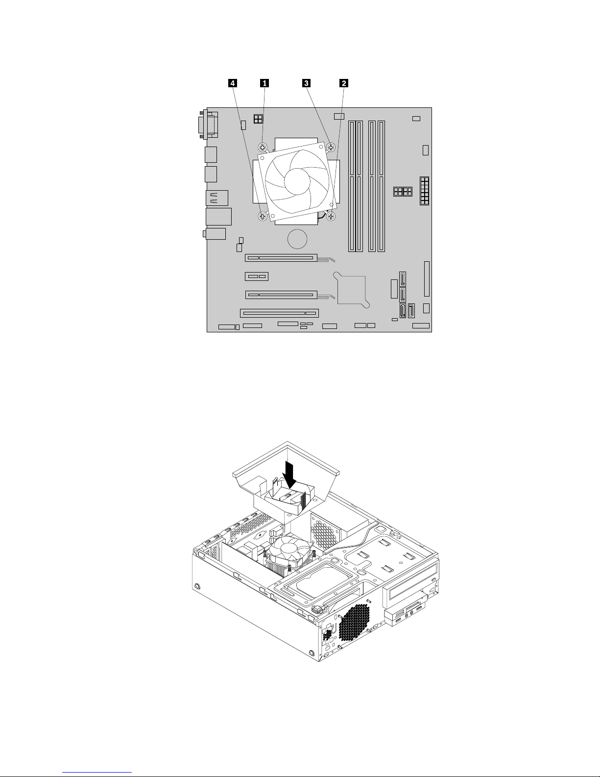
Figure62.Removingtheheatsinkandfanassembly
11.Connectthecableofthenewheatsinkandfanassemblytothemicroprocessorfanconnectoronthe
systemboard.See“Locatingpartsonthesystemboard”onpage14.
12.Positiontheheatsinkfanductonthetopofthenewheatsinkandfanassemblyasshown.Then,press
theheatsinkfanductstraightdownuntilitsnapsintoposition.
Figure63.Installingtheheatsinkfanduct
Chapter5.Installingorreplacinghardware67
Page 80
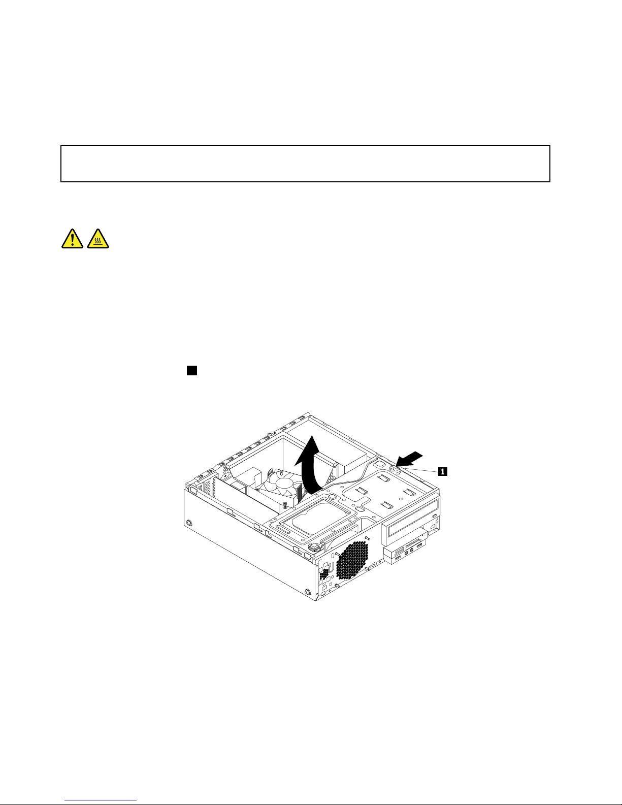
Whattodonext:
•Toworkwithanotherpieceofhardware,gototheappropriatesection.
•Tocompletetheinstallationorreplacement,goto“Completingthepartsreplacement”onpage103.
Replacingthemicroprocessor
Attention:
Donotopenyourcomputerorattemptanyrepairbeforereadingandunderstandingthe“Importantsafetyinformation”
onpagev.
Thissectionprovidesinstructionsonhowtoreplacethemicroprocessor.
CAUTION:
Theheatsinkandmicroprocessormightbeveryhot.T urnoffthecomputerandwaitthreetove
minutestoletthecomputercoolbeforeremovingthecomputercover.
Toreplacethemicroprocessor,dothefollowing:
1.Removeallmediafromthedrivesandturnoffallattacheddevicesandthecomputer.Then,disconnect
allpowercordsfromelectricaloutletsanddisconnectallcablesthatareconnectedtothecomputer.
2.Removethecomputercover.See“Removingthecomputercover”onpage36.
3.Removethefrontbezel.See“Removingandreinstallingthefrontbezel”onpage36.
4.Presstheretainingclip1inthedirectionasshownandpivotthedrivebayassemblyupwardatthe
sametime.
Figure64.Pivotingthedrivebayassemblyupward
5.Removetheheatsinkandfanassembly.See“Replacingtheheatsinkandfanassembly”onpage65.
Note:Donotletthethermalgreaseonthebottomoftheheatsinkandfanassemblygetincontact
withanything.
6.Recordthecableroutingandconnections.Then,locatethesystemboardanddisconnectallcables
connectedtothesystemboard.See“Locatingpartsonthesystemboard”onpage14.
68ThinkCentreM83,M93/pUserGuide
Page 81
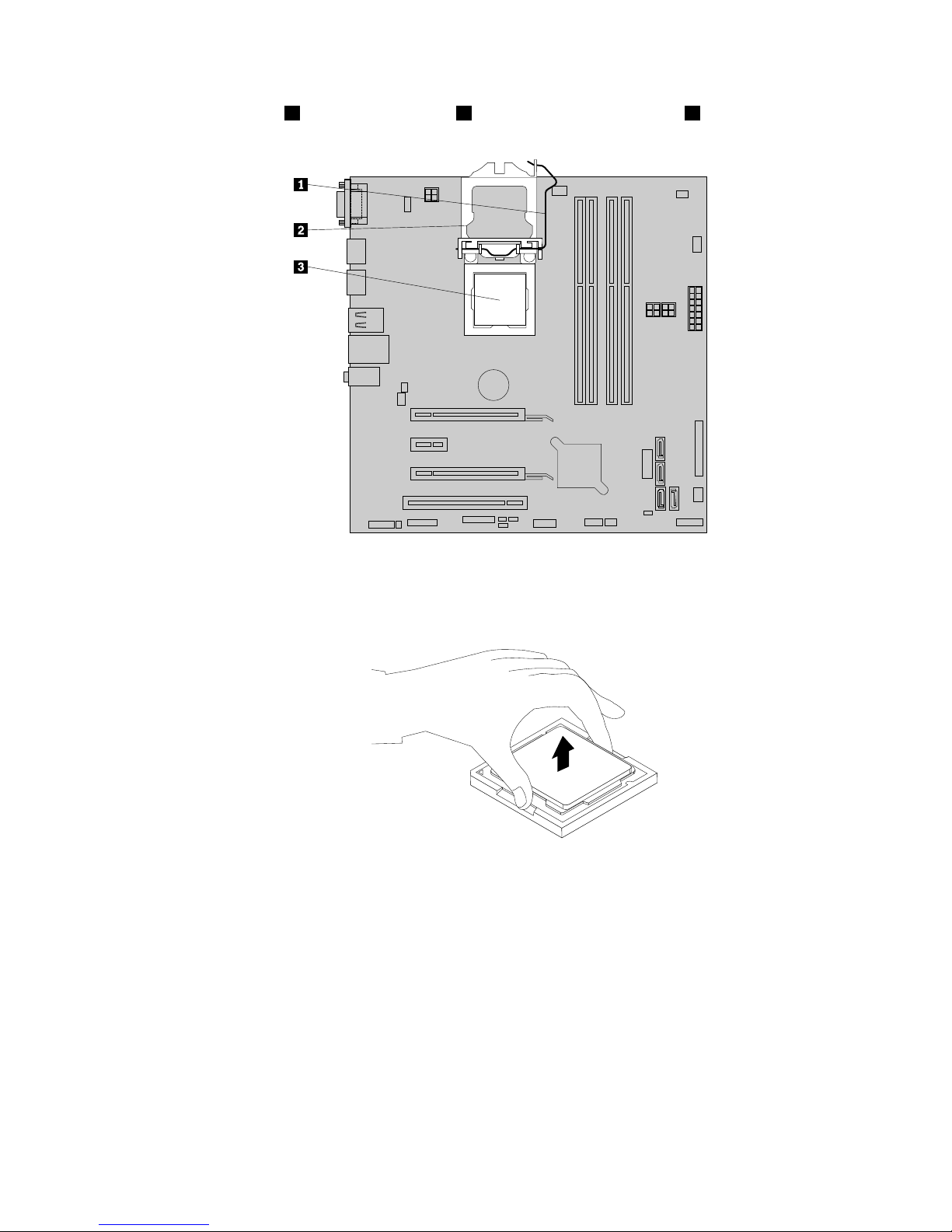
7.Liftthesmallhandle1andopentheretainer2toaccessthemicroprocessor3.
Figure65.Accessingthemicroprocessor
8.Carefullyliftthemicroprocessorstraightupandoutofthemicroprocessorsocket.
Figure66.Removingthemicroprocessor
Notes:
•Yourmicroprocessorandsocketmightlookdifferentfromtheoneillustrated.
•Touchonlytheedgesofthemicroprocessor.Donottouchthegoldcontactsonthebottomof
themicroprocessor.
•Donotdropanythingontothemicroprocessorsocketwhileitisexposed.Thesocketpinsmustbe
keptascleanaspossible.
9.Ensurethatthesmallhandleisintheraisedpositionandthemicroprocessorretainerisfullyopen.
10.Removetheprotectivecoverthatprotectsthegoldcontactsofthenewmicroprocessor.
Chapter5.Installingorreplacinghardware69
Page 82
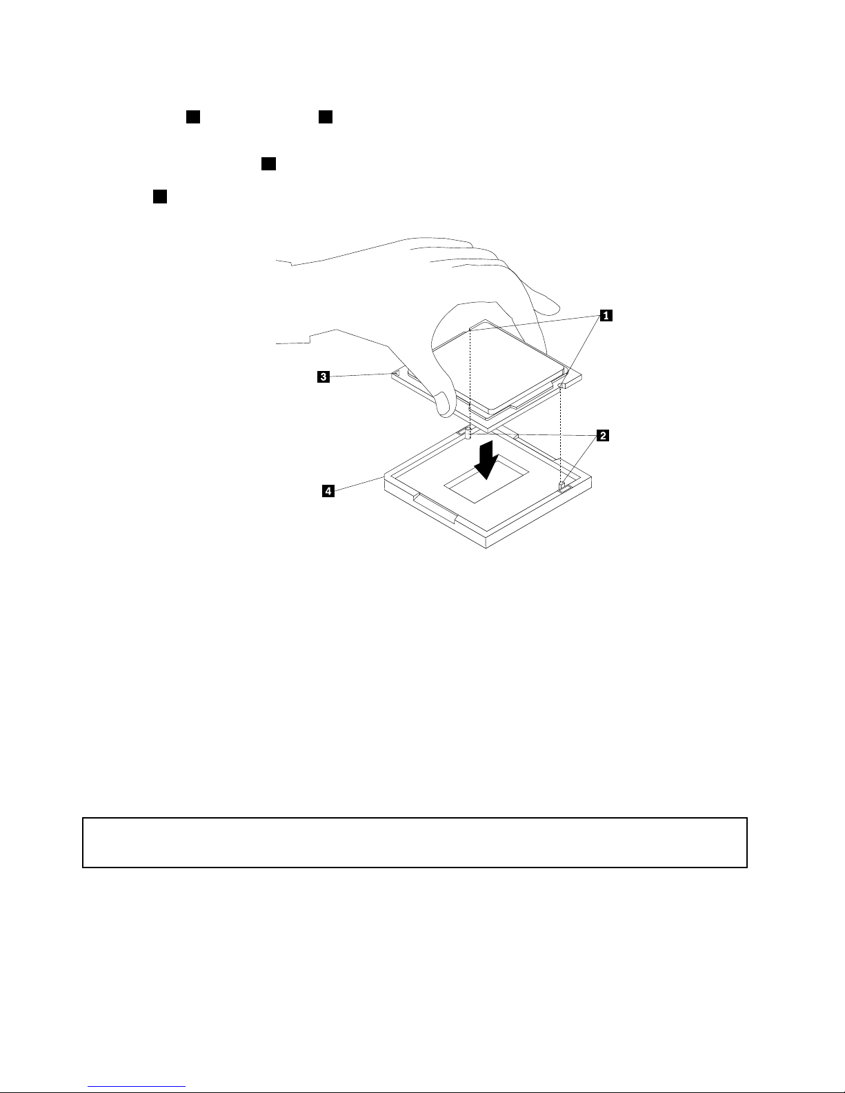
11.Notetheorientationofthenewmicroprocessor.Holdthenewmicroprocessorbyitsedgesandalign
thenotches1onitwiththetabs2inthemicroprocessorsocket.Then,carefullylowerthenew
microprocessorstraightdownintothemicroprocessorsocket.
Note:Thesmalltriangle3ononecornerofthenewmicroprocessoristhemicroprocessororientation
indicator.Thenewmicroprocessorisinthecorrectorientationwhenthisindicatorfacesthebeveled
corner
4ofthemicroprocessorsocket.
Figure67.Installingthemicroprocessor
12.Closethemicroprocessorretainerandlockitintopositionwiththesmallhandletosecurethenew
microprocessorinthesocket.
13.Reinstalltheheatsinkandfanassembly.See“Replacingtheheatsinkandfanassembly”onpage65.
14.Reconnectallcablesthatweredisconnectedfromthesystemboard.See“Locatingpartsonthe
systemboard”onpage14
Whattodonext:
•Toworkwithanotherpieceofhardware,gototheappropriatesection.
•Tocompletethereplacement,goto“Completingthepartsreplacement”onpage103.
Replacingthecoverpresenceswitch
Attention:
Donotopenyourcomputerorattemptanyrepairbeforereadingandunderstandingthe“Importantsafetyinformation”
onpagev.
Thissectionprovidesinstructionsonhowtoreplacethecoverpresenceswitch,whichisalsoknownas
intrusionswitch.
Toreplacethecoverpresenceswitch,dothefollowing:
1.Removeallmediafromthedrivesandturnoffallattacheddevicesandthecomputer.Then,disconnect
allpowercordsfromelectricaloutletsanddisconnectallcablesthatareconnectedtothecomputer.
70ThinkCentreM83,M93/pUserGuide
Page 83
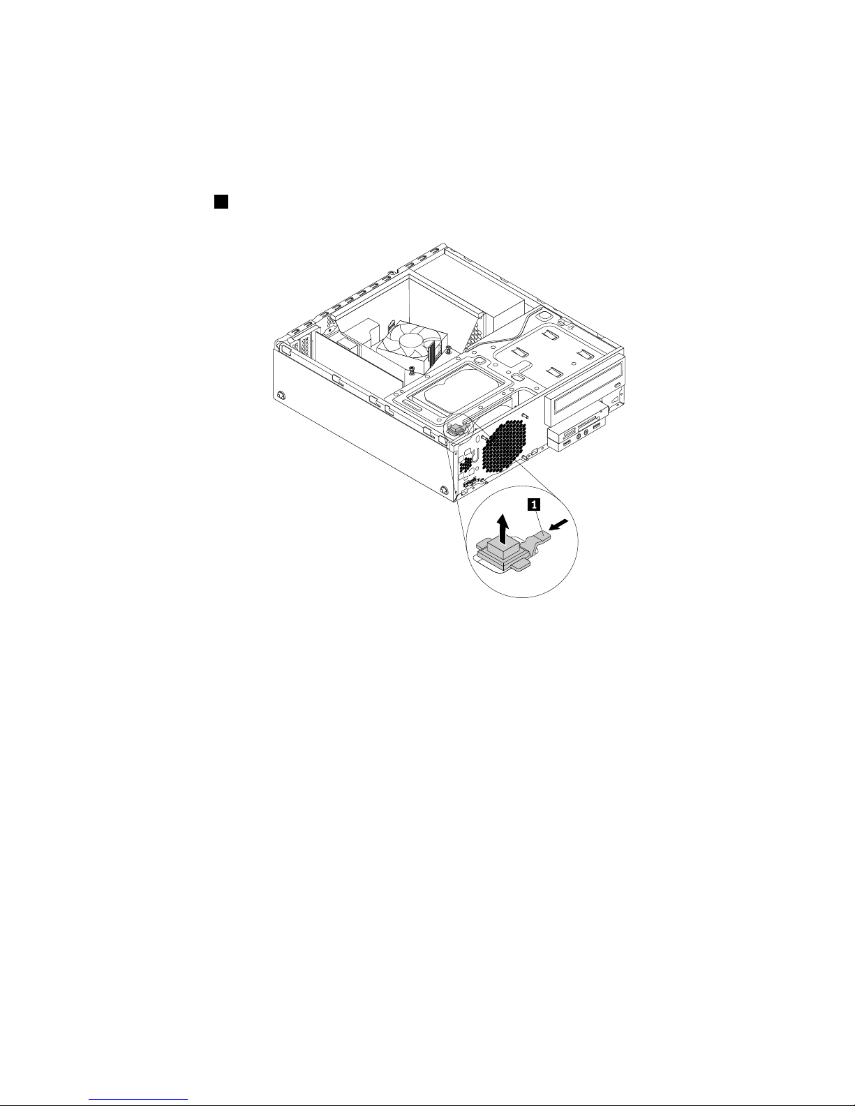
2.Removethecomputercover.See“Removingthecomputercover”onpage36.
3.Removethefrontbezel.See“Removingandreinstallingthefrontbezel”onpage36.
4.Locatethecoverpresenceswitch.See“Locatingcomponents”onpage14.
5.Disconnectthecoverpresenceswitchcablefromthecoverpresenceswitchconnectorsonthesystem
board.
6.Presstheclip1asshownandliftthecoverpresenceswitchuptoremoveitfromthechassis.
Figure68.Removingthecoverpresenceswitch
Chapter5.Installingorreplacinghardware71
Page 84
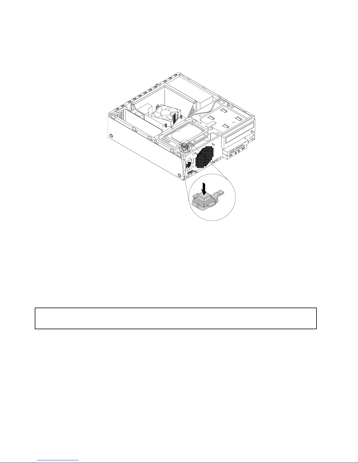
7.Putthenewcoverpresenceswitchintotheholeandpressitdownuntilitsnapsintoposition.
Note:Notetheorientationofthecoverpresenceswitch.
Figure69.Installingthecoverpresenceswitch
8.Connectthecableofthenewcoverpresenceswitchtothecoverpresenceswitchconnectoronthe
systemboard.See“Locatingpartsonthesystemboard”onpage14.
Whattodonext:
•Toworkwithanotherpieceofhardware,gototheappropriatesection.
•Tocompletetheinstallationorreplacement,goto“Completingthepartsreplacement”onpage103.
Replacingtheprimaryharddiskdrive
Attention:
Donotopenyourcomputerorattemptanyrepairbeforereadingandunderstandingthe“Importantsafetyinformation”
onpagev.
Thissectionprovidesinstructionsonhowtoreplacetheprimaryharddiskdrive.
Toreplacetheprimaryharddiskdrive,dothefollowing:
1.Removeallmediafromthedrivesandturnoffallattacheddevicesandthecomputer.Then,disconnect
allpowercordsfromelectricaloutletsanddisconnectallcablesthatareconnectedtothecomputer.
2.Removethecomputercover.See“Removingthecomputercover”onpage36.
3.Removethefrontbezel.See“Removingandreinstallingthefrontbezel”onpage36.
72ThinkCentreM83,M93/pUserGuide
Page 85
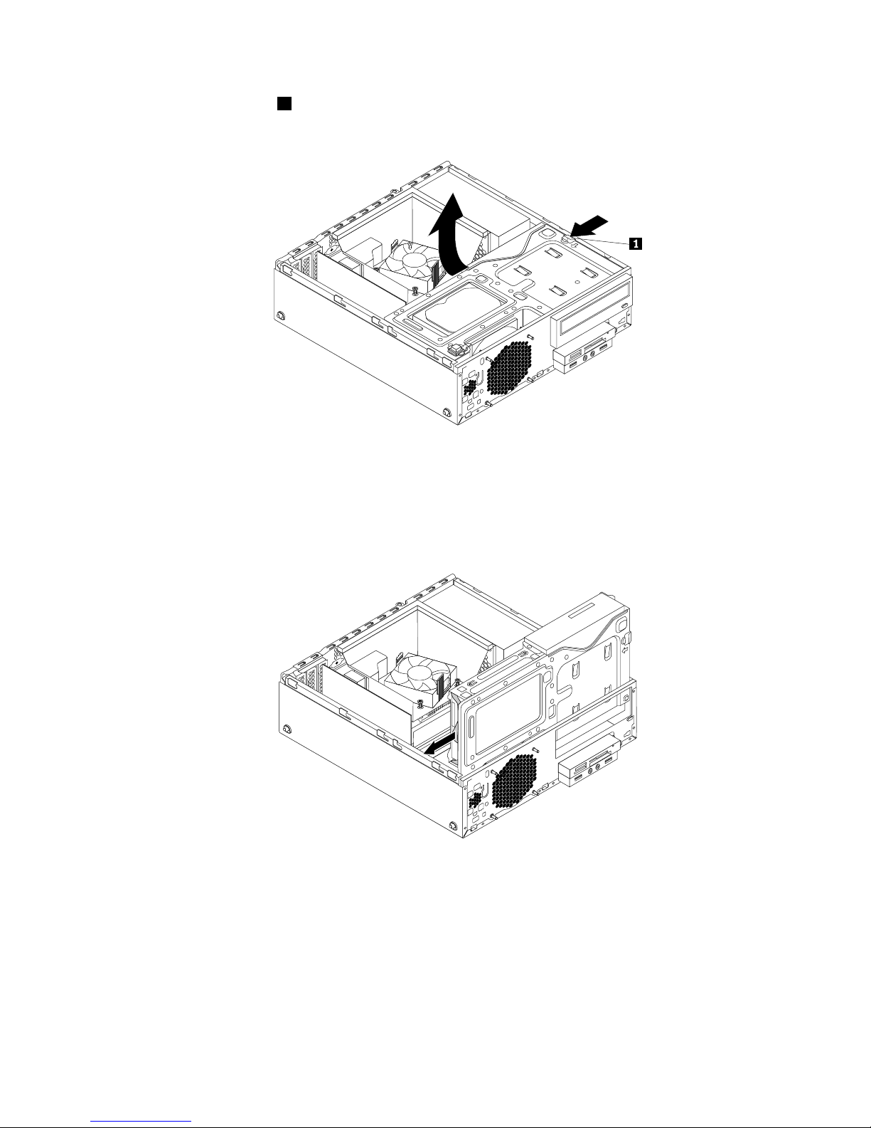
4.Presstheretainingclip1inthedirectionasshownandpivotthedrivebayassemblyupwardatthe
sametime.
Figure70.Pivotingthedrivebayassemblyupward
5.Locatetheprimaryharddiskdrive.See“Locatinginternaldrives”onpage17.
6.Disconnectthesignalcableandthepowercablefromtheprimaryharddiskdrive.
7.Pullonthebluehandletoslidetheprimaryharddiskdriveoutofthedrivebay.
Figure71.Removingtheprimaryharddiskdrive
8.Flexthesidesofthebluebrackettoremovetheprimaryharddiskdrivefromthebracket.
Chapter5.Installingorreplacinghardware73
Page 86
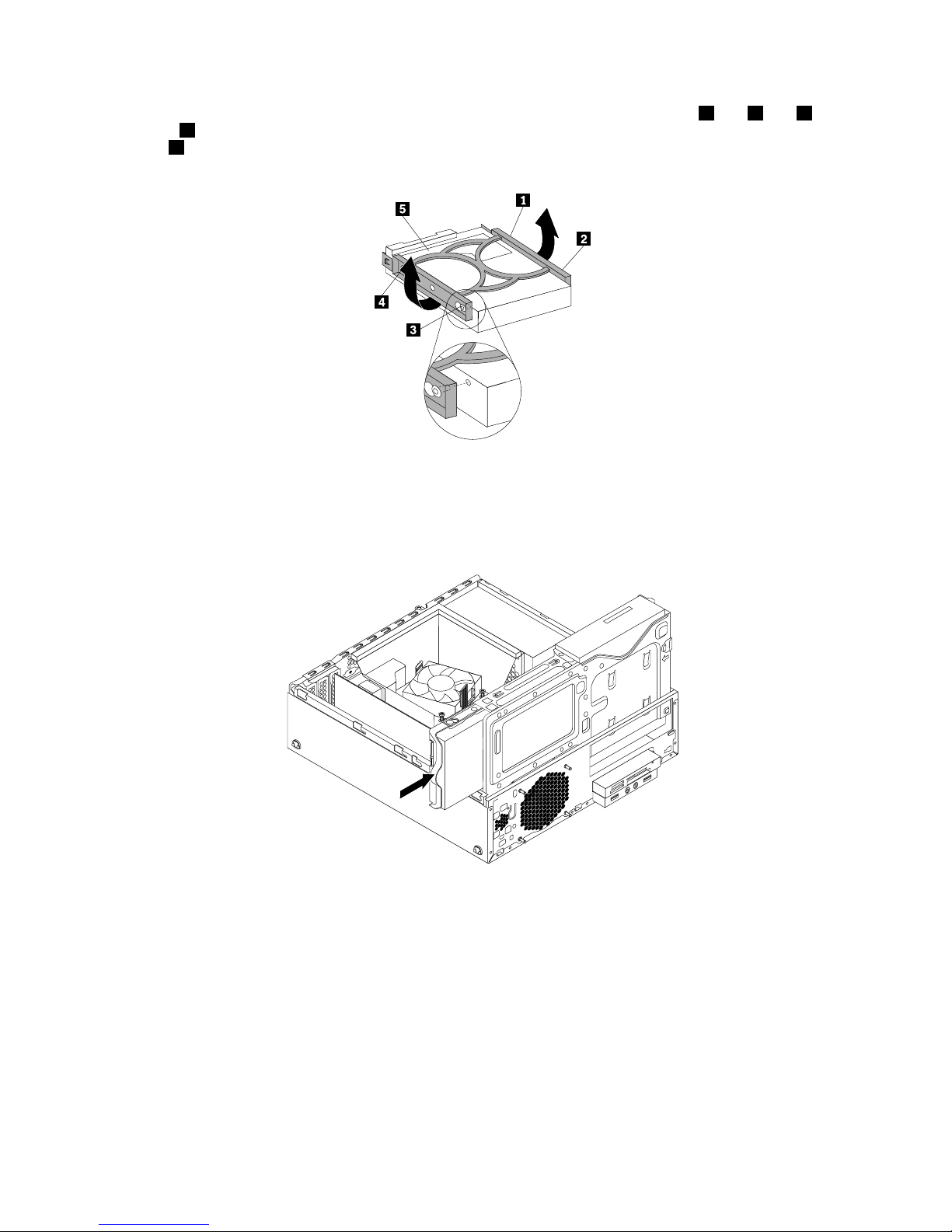
9.T oinstallanewharddiskdriveintothebluebracket,exthebracketandalignpin1,pin2,pin3,
andpin4onthebracketwiththecorrespondingholesintheharddiskdrive.Donottouchthecircuit
board5onthebottomoftheharddiskdrive.
Figure72.Installingtheharddiskdriveintothebracket
10.Slidethenewprimaryharddiskdrivewithbracketintotheprimaryharddiskdrivebayuntilitsnaps
intoposition.
Figure73.Installingtheprimaryharddiskdrive
11.Connectthesignalcableandthepowercabletothenewprimaryharddiskdrive.
Whattodonext:
•Toworkwithanotherpieceofhardware,gototheappropriatesection.
•Tocompletetheinstallationorreplacement,goto“Completingthepartsreplacement”onpage103.
Installingorreplacingthesecondaryharddiskdrive
Thissectionprovidesinstructionsonhowtoinstallorreplacethesecondaryharddiskdrive.
Note:Thesecondaryharddiskdriveisonlyavailableinsomemodels.
74ThinkCentreM83,M93/pUserGuide
Page 87
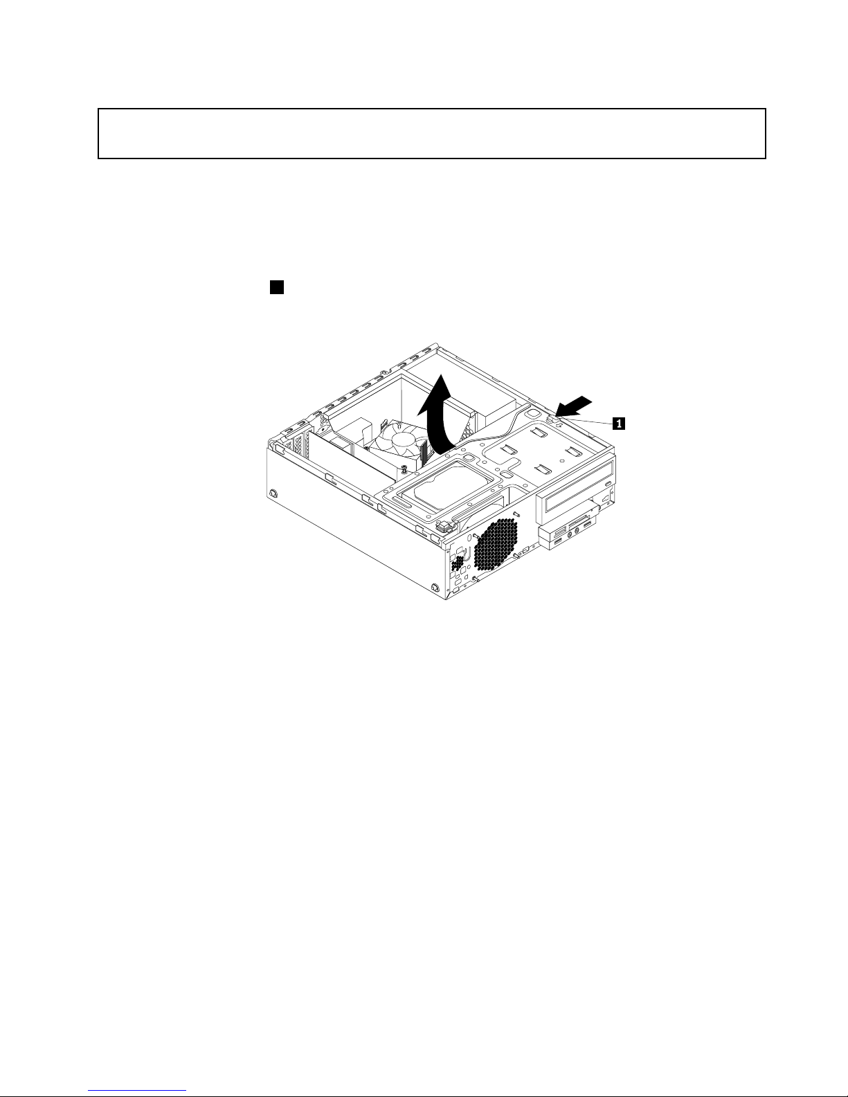
Installingthesecondaryharddiskdrive
Attention:
Donotopenyourcomputerorattemptanyrepairbeforereadingandunderstandingthe“Importantsafetyinformation”
onpagev.
Toinstallthesecondaryharddiskdrive,dothefollowing:
1.Removeallmediafromthedrivesandturnoffallattacheddevicesandthecomputer.Then,disconnect
allpowercordsfromelectricaloutletsanddisconnectallcablesthatareconnectedtothecomputer.
2.Removethecomputercover.See“Removingthecomputercover”onpage36.
3.Removethefrontbezel.See“Removingandreinstallingthefrontbezel”onpage36.
4.Presstheretainingclip1inthedirectionasshownandpivotthedrivebayassemblyupwardatthe
sametime.
Figure74.Pivotingthedrivebayassemblyupward
Chapter5.Installingorreplacinghardware75
Page 88
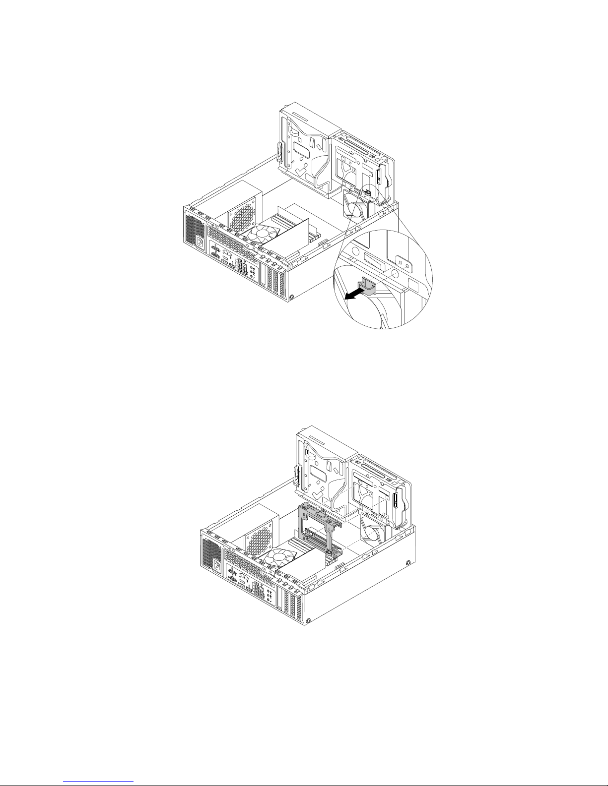
5.Removethecablecliponthebottomoftheprimaryharddiskdrivebayasshown.
3
4
5 6
7 8
Figure75.Removingthecableclip
6.Alignthefourholesinthesecondaryharddiskdrivecarrierwiththecorrespondingfourtabsonthe
bottomoftheprimaryharddiskdrivebayasshown.Then,positionthecarrierontothebottomofthe
primaryharddiskdrivebaysothatthetabsonthebaypassthroughtheholesinthecarrier.
3
4
5
6 7
8
Figure76.Positioningthecarrierontothebottomoftheprimaryharddiskdrivebay
76ThinkCentreM83,M93/pUserGuide
Page 89
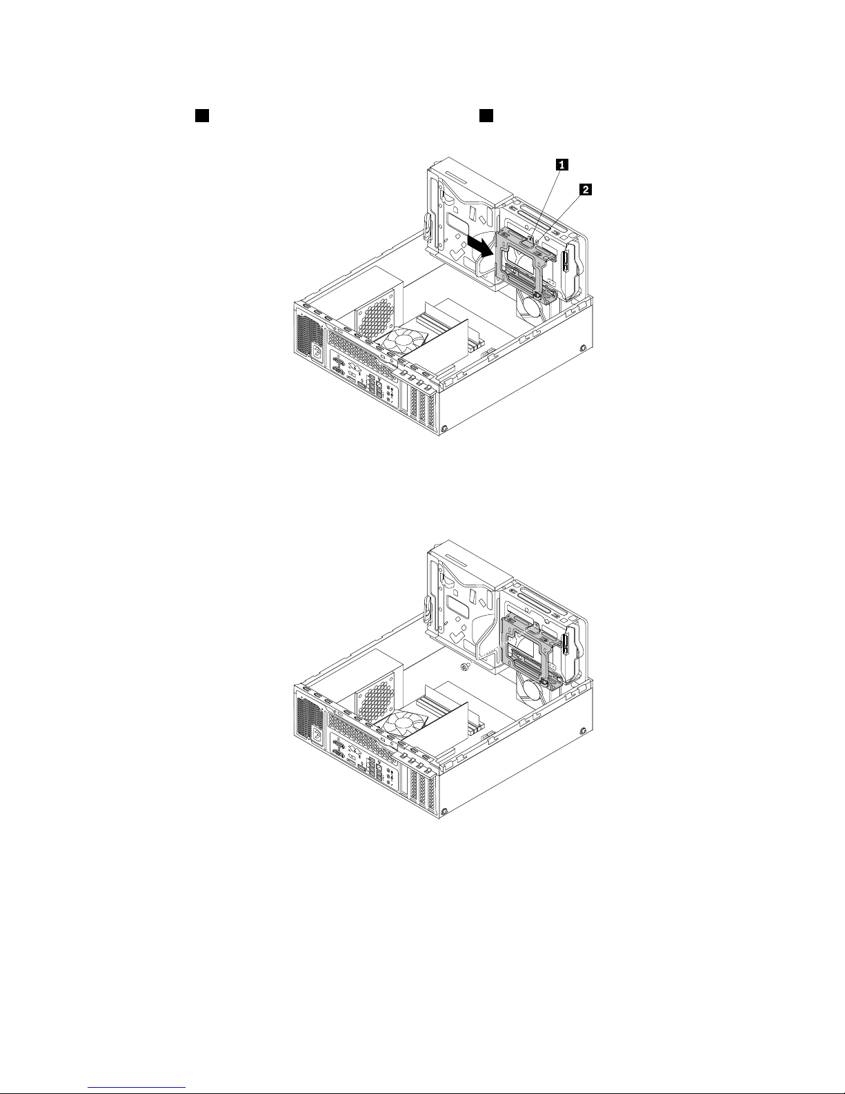
7.Slidethesecondaryharddiskdrivecarriertotheleftofthechassisuntilitsnapsintopositionandthe
screwhole1inthecarrierisalignedwiththescrewhole2inthebay.
3
4
5
6 7
8
Figure77.Installingthesecondaryharddiskdrivecarrier
8.Installthescrewtosecurethesecondaryharddiskdrivecarriertothechassis.
3
4
5
6 7
8
Figure78.Installingthescrewtosecurethesecondaryharddiskdrivecarrier
9.Flexthesidesofthebluebrackettoremovetheprimaryharddiskdrivefromthebracket.
Chapter5.Installingorreplacinghardware77
Page 90
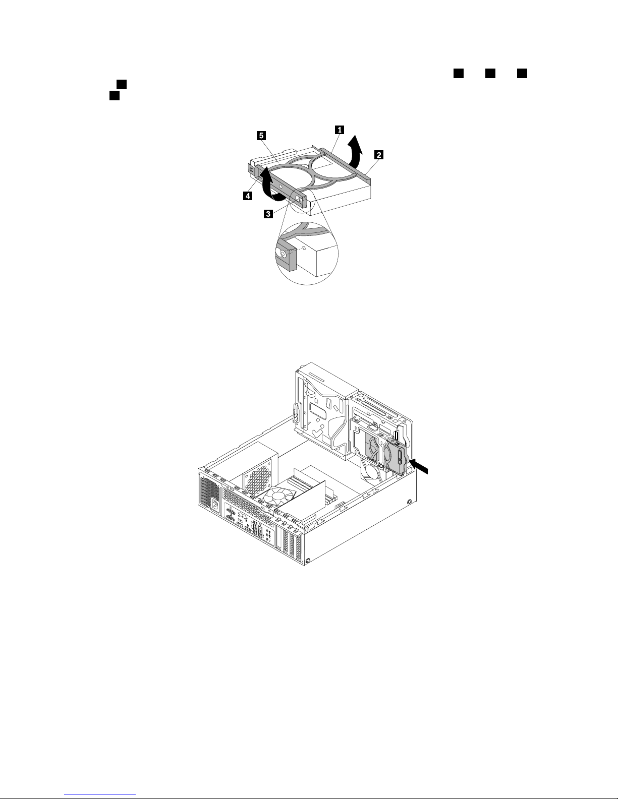
10.T oinstallanewharddiskdriveintothebluebracket,exthebracketandalignpin1,pin2,pin3,
andpin4onthebracketwiththecorrespondingholesintheharddiskdrive.Donottouchthecircuit
board5onthebottomoftheharddiskdrive.
Figure79.Installingtheharddiskdriveintothebracket
11.Slidethenewsecondaryharddiskdriveintothecarrieruntilitsnapsintoposition.
3
4
5
6 7
8
Figure80.Installingthesecondaryharddiskdrive
12.Connectthesignalcableandthepowercabletothenewsecondaryharddiskdrive.
Whattodonext:
•Toworkwithanotherpieceofhardware,gototheappropriatesection.
•Tocompletetheinstallationorreplacement,goto“Completingthepartsreplacement”onpage103
.
78ThinkCentreM83,M93/pUserGuide
Page 91
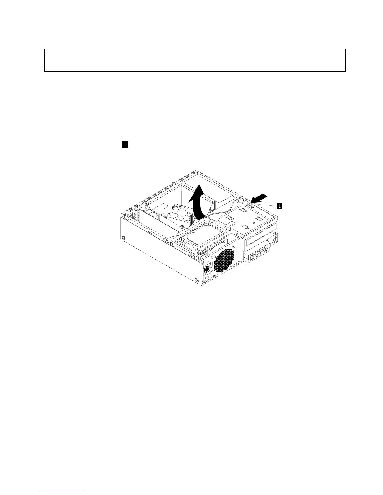
Replacingthesecondaryharddiskdrive
Attention:
Donotopenyourcomputerorattemptanyrepairbeforereadingandunderstandingthe“Importantsafetyinformation”
onpagev.
Thissectionprovidesinstructionsonhowtoreplacethesecondaryharddiskdrive.
Toreplacethesecondaryharddiskdrive,dothefollowing:
1.Removeallmediafromthedrivesandturnoffallattacheddevicesandthecomputer.Then,disconnect
allpowercordsfromelectricaloutletsanddisconnectallcablesthatareconnectedtothecomputer.
2.Removethecomputercover.See“Removingthecomputercover”onpage36.
3.Removethefrontbezel.See“Removingandreinstallingthefrontbezel”onpage36.
4.Presstheretainingclip1inthedirectionasshownandpivotthedrivebayassemblyupwardatthe
sametime.
Figure81.Pivotingthedrivebayassemblyupward
5.Locatethesecondaryharddiskdrivebay.See“Locatinginternaldrives”onpage17.
6.Disconnectthesignalcableandthepowercablefromtheprimaryharddiskdriveandsecondary
harddiskdrive.
Chapter5.Installingorreplacinghardware79
Page 92
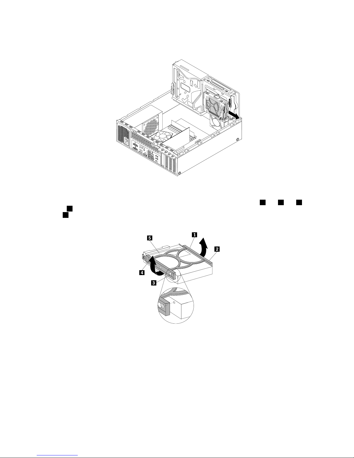
7.Pullthebluehandletoslidethesecondaryharddiskdriveoutofthecarrier.
3
4
5
6 7
8
Figure82.Removingthesecondaryharddiskdrive
8.T oinstallanewharddiskdriveintothebluebracket,exthebracketandalignpin1,pin2,pin3,
andpin4onthebracketwiththecorrespondingholesintheharddiskdrive.Donottouchthecircuit
board5onthebottomoftheharddiskdrive.
Figure83.Installingtheharddiskdriveintothebracket
80ThinkCentreM83,M93/pUserGuide
Page 93
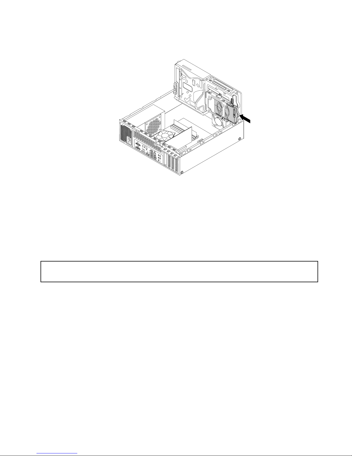
9.Slidethenewsecondaryharddiskdriveintothecarrieruntilitsnapsintoposition.
3
4
5
6 7
8
Figure84.Installingthesecondaryharddiskdrive
10.Connectthesignalcableandthepowercabletotheprimaryharddiskdriveandthenewsecondary
harddiskdrive.
Whattodonext:
•Toworkwithanotherpieceofhardware,gototheappropriatesection.
•Tocompletetheinstallationorreplacement,goto“Completingthepartsreplacement”onpage103.
Installingthesolid-statedrive
Attention:
Donotopenyourcomputerorattemptanyrepairbeforereadingandunderstandingthe“Importantsafetyinformation”
onpagev
.
Thissectionprovidesinstructionsonhowtoinstallthe2.5-inchsolid-statedrive.
Toinstallthesolid-statedrive,dothefollowing:
Chapter5.Installingorreplacinghardware81
Page 94
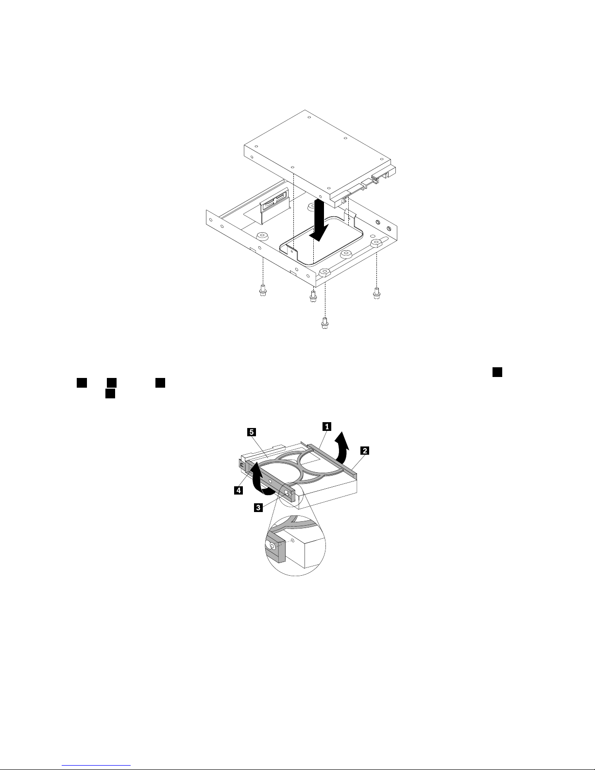
1.Installthesolid-statedriveintotheadapter.Then,installthefourscrewstosecurethesolid-state
drivetotheadapter.
Figure85.Installingthesolid-statedriveintotheadapter
2.T oinstalltheadapterwithasolid-statedriveintothebluebracket,exthebracketandalignpin1,pin
2,pin3,andpin4onthebracketwiththecorrespondingholesintheadapter.Donottouchthecircuit
board5onthebottomofthesolid-statedrive.
Figure86.Installingtheadapterwithasolid-statedriveintothebracket
3.Installthesolid-statedriveassemblyintotheharddiskdrivebay.See“Replacingtheprimaryhard
diskdrive”onpage72.
Whattodonext:
•Toworkwithanotherpieceofhardware,gototheappropriatesection.
•Tocompletetheinstallationorreplacement,goto“Completingthepartsreplacement”onpage103
.
82ThinkCentreM83,M93/pUserGuide
Page 95
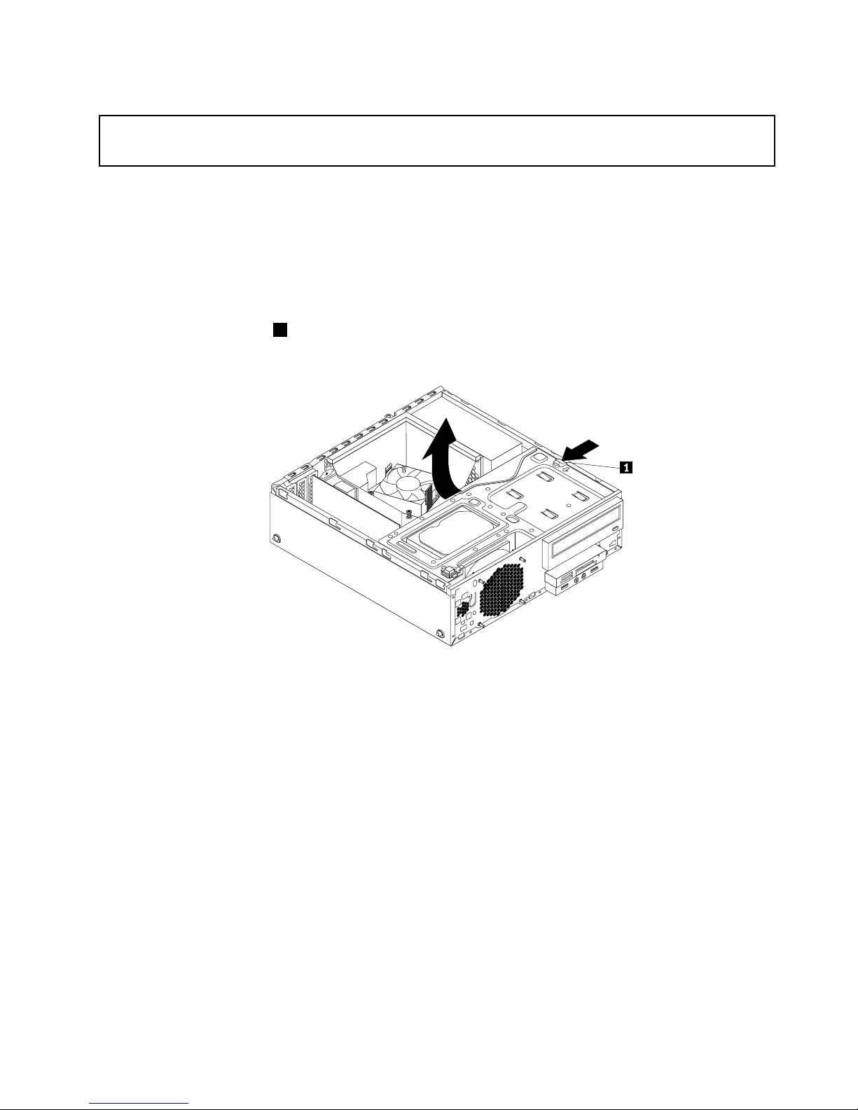
Replacingthefrontfanassembly
Attention:
Donotopenyourcomputerorattemptanyrepairbeforereadingandunderstandingthe“Importantsafetyinformation”
onpagev
.
Thissectionprovidesinstructionsonhowtoreplacethefrontfanassembly.
Toreplacethefrontfanassembly,dothefollowing:
1.Removeallmediafromthedrivesandturnoffallattacheddevicesandthecomputer.Then,disconnect
allpowercordsfromelectricaloutletsanddisconnectallcablesthatareconnectedtothecomputer.
2.Removethecomputercover.See“Removingthecomputercover”onpage36.
3.Removethefrontbezel.See“Removingandreinstallingthefrontbezel”onpage36.
4.Presstheretainingclip1inthedirectionasshownandpivotthedrivebayassemblyupwardatthe
sametime.
Figure87.Pivotingthedrivebayassemblyupward
5.Disconnectthefrontfanassemblycablefromthesystemfanconnectoronthesystemboard.
Note:Foreasieraccesstothesystemfanconnectoronthesystemboard,youmightneedtoremove
theheatsinkfanduct.See“Replacingtheheatsinkandfanassembly”onpage65.
Chapter5.Installingorreplacinghardware83
Page 96
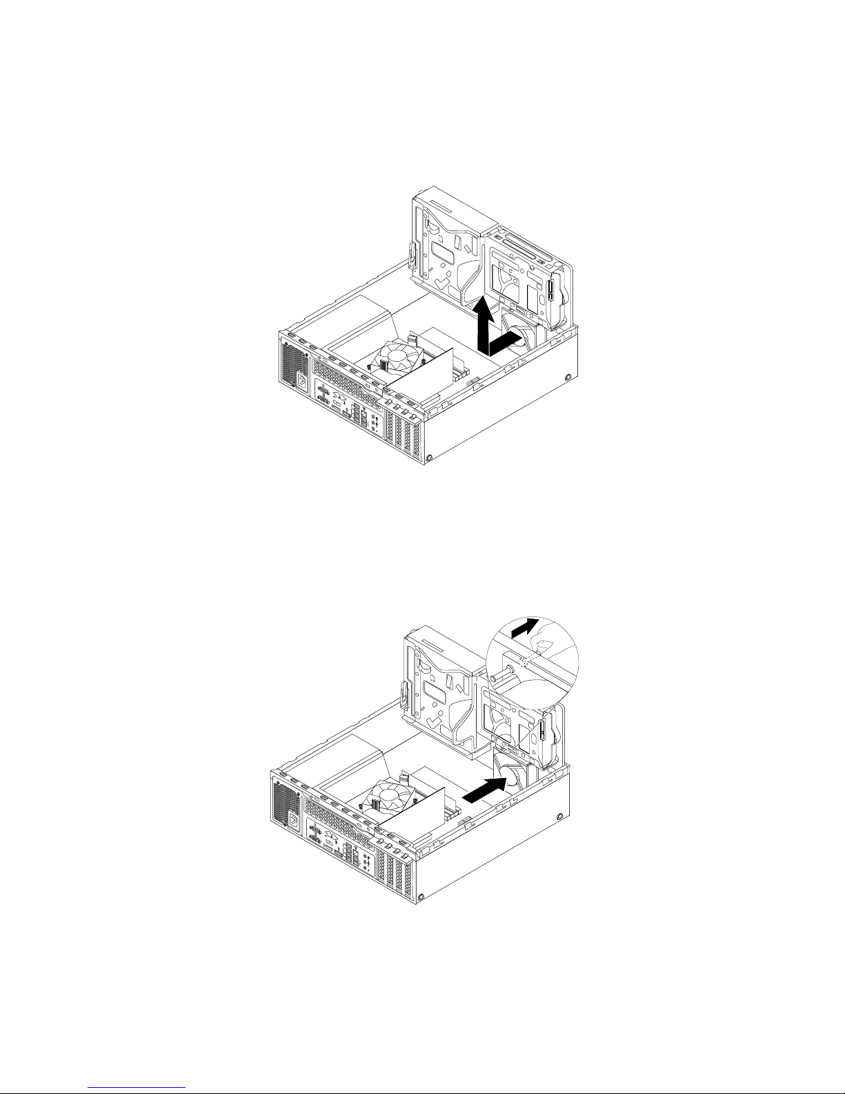
6.Thefrontfanassemblyisattachedtothechassisbyfourrubbermounts.Removethefrontfanassembly
bybreakingorcuttingtherubbermountsandgentlypullingthefrontfanassemblyoutofthechassis.
Note:Thenewfrontfanassemblycomeswithfournewrubbermountsattached.
3
4
5 6
7 8
Figure88.Removingthefrontfanassembly
7.Installthenewfrontfanassemblybyaligningthefournewrubbermountsonthenewfrontfanassembly
withthecorrespondingholesinthechassisandpushtherubbermountsthroughtheholes.Pullthe
tipofeachrubbermountfromtheoutersideofthefrontpaneluntilallrubbermountsgothroughthe
holesandsecurethefrontfanassemblyinplace.
3
4
5 6
7 8
Figure89.Installingthefrontfanassembly
8.Connectthecableofthenewfrontfanassemblytothepowerfanconnectoronthesystemboard.See
“Locatingpartsonthesystemboard”onpage14.
84ThinkCentreM83,M93/pUserGuide
Page 97
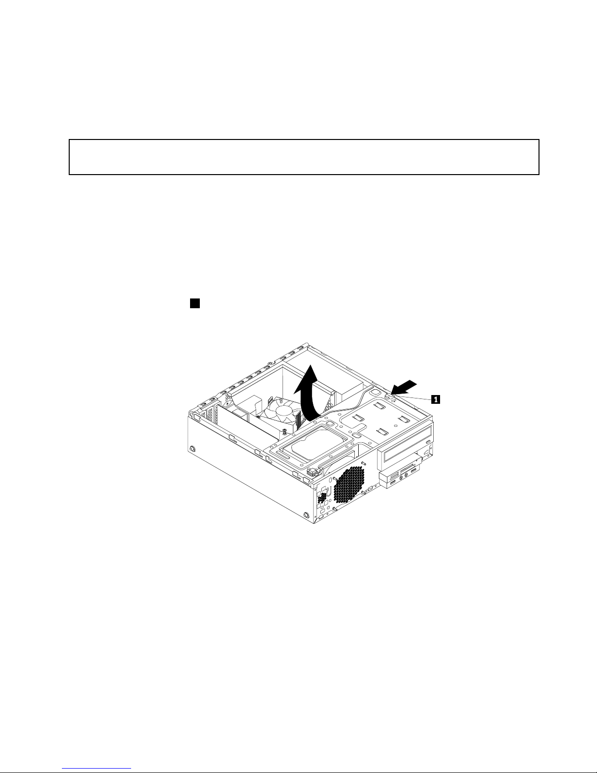
Whattodonext:
•Toworkwithanotherpieceofhardware,gototheappropriatesection.
•Tocompletetheinstallationorreplacement,goto“Completingthepartsreplacement”onpage103.
ReplacingthefrontaudioandUSBassembly
Attention:
Donotopenyourcomputerorattemptanyrepairbeforereadingandunderstandingthe“Importantsafetyinformation”
onpagev.
ThissectionprovidesinstructionsonhowtoreplacethefrontaudioandUSBassembly.
ToreplacethefrontaudioandUSBassembly,dothefollowing:
1.Removeallmediafromthedrivesandturnoffallattacheddevicesandthecomputer.Then,disconnect
allpowercordsfromelectricaloutletsanddisconnectallcablesthatareconnectedtothecomputer.
2.Removethecomputercover.See“Removingthecomputercover”onpage36.
3.Removethefrontbezel.See“Removingandreinstallingthefrontbezel”onpage36.
4.LocatethefrontaudioandUSBassembly.See“Locatingcomponents”onpage14.
5.Presstheretainingclip1inthedirectionasshownandpivotthedrivebayassemblyupwardatthe
sametime.
Figure90.Pivotingthedrivebayassemblyupward
6.DisconnectthefrontaudioandUSBassemblycablesfromthesystemboard.
Chapter5.Installingorreplacinghardware85
Page 98
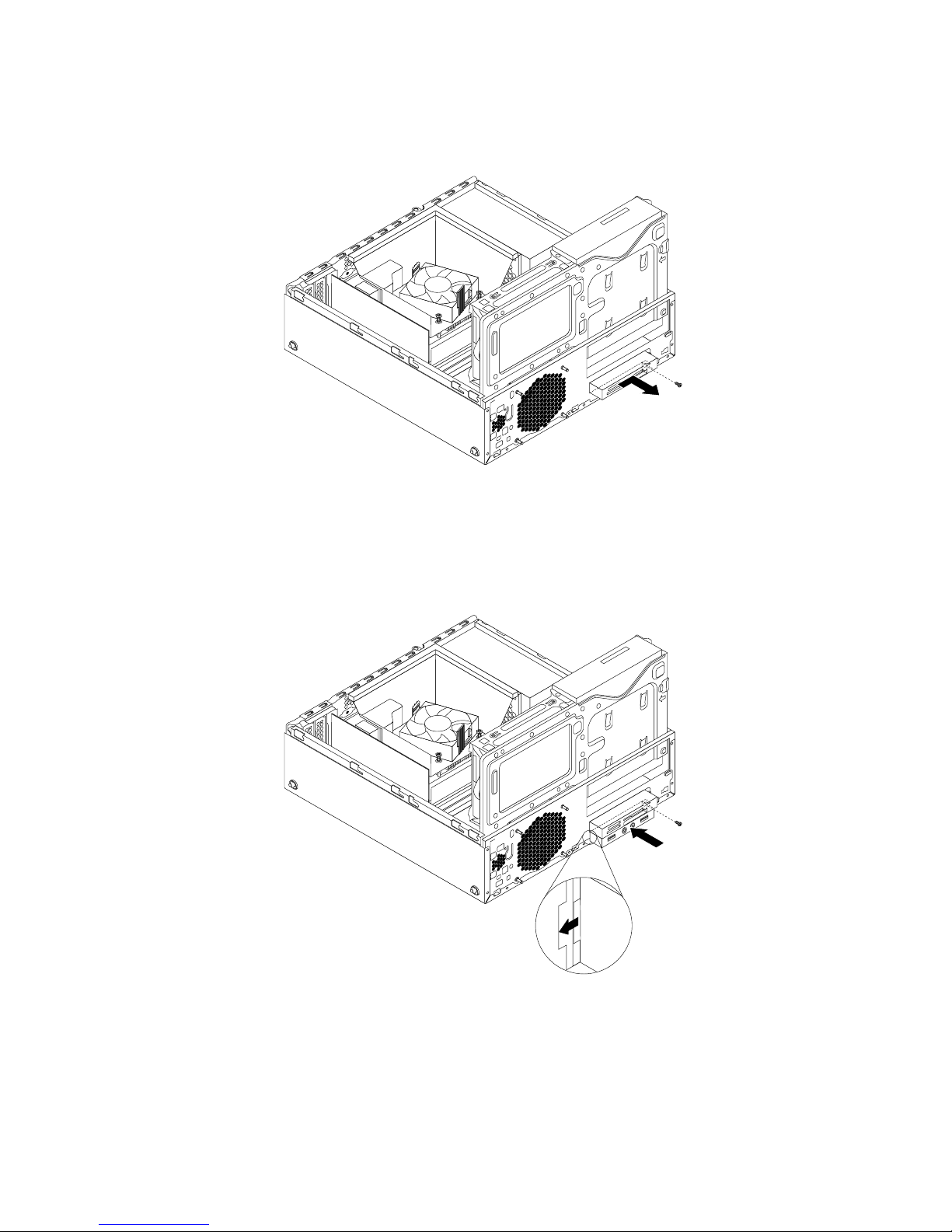
7.RemovethescrewthatsecuresthefrontaudioandUSBassembly.Then,removethefrontaudio
andUSBassemblyfromthechassis.
Figure91.RemovingthefrontaudioandUSBassembly
8.InstallthenewfrontaudioandUSBassemblyintothechassisuntilitsnapsintoposition.Then,pushthe
newfrontaudioandUSBassemblytotheleftuntilthescrewholeinthemetalbracketofthefrontaudio
andUSBassemblyisalignedwiththecorrespondingholeinthechassis.
Figure92.InstallingthefrontaudioandUSBassembly
9.ConnectthecablesofthenewfrontaudioandUSBassemblycablestothefrontaudioconnectorand
thefrontUSBconnector1onthesystemboard.See“Locatingpartsonthesystemboard”onpage14.
Whattodonext:
•Toworkwithanotherpieceofhardware,gototheappropriatesection.
86ThinkCentreM83,M93/pUserGuide
Page 99
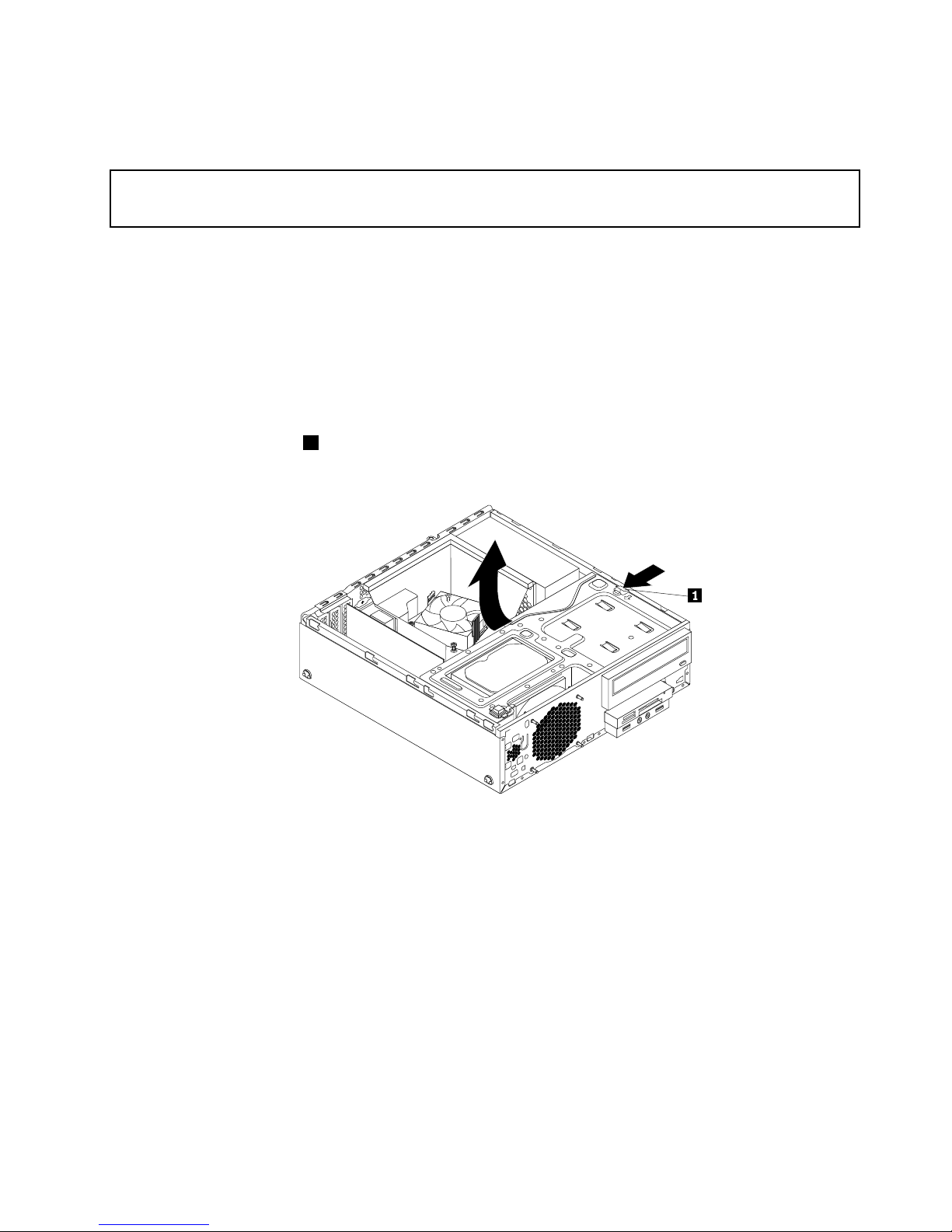
•Tocompletetheinstallationorreplacement,goto“Completingthepartsreplacement”onpage103.
Replacingtheinternalspeaker
Attention:
Donotopenyourcomputerorattemptanyrepairbeforereadingandunderstandingthe“Importantsafetyinformation”
onpagev.
Thissectionprovidesinstructionsonhowtoreplacetheinternalspeaker.
Note:Theinternalspeakerisonlyavailableinsomemodels.
Toreplacetheinternalspeaker,dothefollowing:
1.Removeallmediafromthedrivesandturnoffallattacheddevicesandthecomputer.Then,disconnect
allpowercordsfromelectricaloutletsanddisconnectallcablesthatareconnectedtothecomputer.
2.Removethecomputercover.See“Removingthecomputercover”onpage36.
3.Removethefrontbezel.See“Removingandreinstallingthefrontbezel”onpage36.
4.Presstheretainingclip1inthedirectionasshownandpivotthedrivebayassemblyupwardatthe
sametime.
Figure93.Pivotingthedrivebayassemblyupward
5.Disconnectthecableoftheinternalspeakerfromtheinternalspeakerconnectoronthesystemboard.
Chapter5.Installingorreplacinghardware87
Page 100
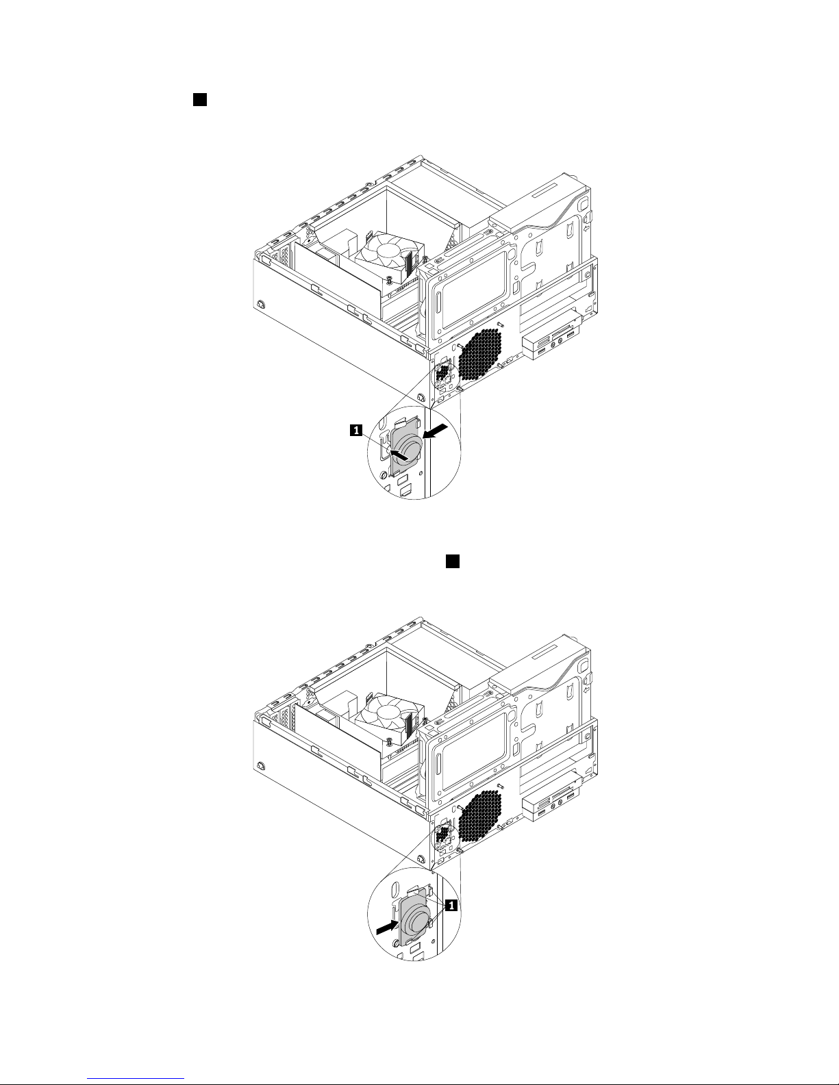
6.Pressthetab1ontheinnersideofthefrontpanelandslidetheinternalspeakertowardsthefrontfan
assemblytoremoveit.
Figure94.Removingtheinternalspeaker
7.Alignthenewinternalspeakerwiththefourmetalclips1ontheinnersideofthefrontpanel,andthen
slidetheinternalspeakertotheleftsideofthechassisuntilitsnapsintoposition.
Figure95.Installingtheinternalspeaker
88ThinkCentreM83,M93/pUserGuide
 Loading...