

Page 1

ThinkServer
InstallationandUserGuide
MachineTypes:1045,1046,1047,and1048
Page 2

Note
Beforeusingthisinformationandtheproductitsupports,besuretoreadandunderstandthefollowing:
•TheImportantNoticesthatcomeswithyourproduct
•TheSafetyInformationandtheWarrantyandSupportInformationonthedocumentationDVDthatcomes
withyourproduct
•AppendixC“Notices”onpage107
SecondEdition(February2011)
©CopyrightLenovo2010,2011.
LENOVOproducts,data,computersoftware,andserviceshavebeendevelopedexclusivelyatprivateexpenseandare
soldtogovernmentalentitiesascommercialitemsasdenedby48C.F.R.2.101withlimitedandrestrictedrightsto
use,reproductionanddisclosure.
LIMITEDANDRESTRICTEDRIGHTSNOTICE:Ifproducts,data,computersoftware,orservicesaredeliveredpursuant
aGeneralServicesAdministration“GSA”contract,use,reproduction,ordisclosureissubjecttorestrictionssetforth
inContractNo.GS-35F-05925.
Page 3

Contents
Safetyinformation..........iii
Chapter1.Generalinformation.....1
Introduction.................1
Noticesandstatementsinthedocument.....1
Relateddocumentation............2
Chapter2.Serversetuproadmap...3
Chapter3.Featuresand
technologies..............5
Whatisincludedwithyourserver........5
Features..................5
Specications................5
Softwareprograms..............7
EasyStartup...............7
EasyManage...............7
Reliability,availability,andserviceability......7
Chapter4.Locatingparts,controls,
LEDs,andconnectors.........9
Frontview.................9
Rearview.................10
Frontcontrolpanel.............11
Locatingservercomponents.........13
Locatingpartsonthesystemboard......14
Locatingconnectorsonthebackplane.....16
Chapter5.Installing,removing,or
replacinghardware..........17
Guidelines................17
Basicguidelines............17
Systemreliabilityguidelines........18
Handlingstatic-sensitivedevices.....18
Workinginsidetheserverwiththepoweron.19
Removingtheservercover..........19
Installing,removing,orreplacingoptionalhardware
devices.................20
Installingorremovingamemorymodule...20
Removingorinstallinginternaldrives....23
Removingorinstallingtherisercard
assembly...............34
InstallingorremovingaPCIcard......36
Installing,removing,orreplacinghardware
devices.................38
Removingorinstallingthesystemboard
battery................38
RemovingorinstallingtheRAIDcontroller..40
RemovingorinstallingtheEthernetcard...50
Removingorinstallingthemicroprocessorfan
duct.................51
Removingorinstallingthepowersupply...52
Removingorinstallingthesystemfans...55
Removingorinstallingtheheatsink....58
Removingorinstallingthemicroprocessor..61
Completingthepartsreplacement.......65
Installingtheservercover........65
Connectingthecables..........65
Turningontheserver..........66
Updatingtheserverconguration.....66
Turningofftheserver..........66
Connectingexternaldevices.......67
Chapter6.Conguringtheserver..69
UsingtheSetupUtilityprogram........69
StartingtheSetupUtilityprogram.....70
IntroductionoftheBIOSitems.......70
Usingpasswords............77
RAIDcontrollers..............78
UsingtheThinkServerEasyStartupprogram...79
BeforeyouusetheEasyStartupDVD....79
Setupandconguration.........79
ConguringRAID............80
Typicaloperatingsysteminstallation....80
Onboard1068ESASRAIDcontrollerConguration
Utilityprogram...............81
InstallingtheSASSGPIOcables......81
StartingtheCongurationUtilityprogram..81
AccessingtheAdapterPropertieswindow..82
SASRAIDsettings...........83
CreatingordeletingtheRAID1array....83
AccessingtheSASTopologywindow....84
ConguringtheGigabitEthernetcontroller....84
Updatingthermware............84
UsingtheEasyUpdateFirmwareUpdater
program...............84
InstallingtheThinkServerEasyManageprogram.85
Chapter7.Troubleshooting......87
Troubleshootingtables...........87
DVDdriveproblems...........87
Generalproblems............88
Harddiskdriveproblems.........88
Intermittentproblems..........88
©CopyrightLenovo2010,2011
i
Page 4

Keyboard,mouse,orpointing-device
problems...............89
Memoryproblems...........89
Microprocessorproblems........90
Monitorproblems............91
Optional-deviceproblems........92
Powerproblems............93
Serialportproblems...........94
Softwareproblems...........95
UniversalSerialBus(USB)portproblems..96
Solvingpowerproblems...........96
SolvingEthernetcontrollerproblems......96
Solvingundeterminedproblems........97
Eventlogs................98
Viewingeventlogswithoutrestartingthe
server................98
Systemeventlog..............99
DiagnosticLEDsonthefrontcontrolpanel...99
Onboarddebugdigitron...........99
AppendixA.RAIDbatterycard
assembly..............101
Specications...............101
Batterylifeanddataretentiontime.....101
Beforeyoucall...............103
Usingthedocumentation..........103
GettinghelpandinformationfromtheWorldWide
Web...................103
LenovoSupportWebsite..........104
Callingforservice.............104
Usingotherservices............105
Purchasingadditionalservices........105
LenovoproductserviceinformationforTaiwan..105
AppendixC.Notices........107
Trademarks................108
Importantnotes..............108
Productrecyclinganddisposal........108
Particulatecontamination..........109
Turkishstatementofcompliance.......110
Batteryreturnprogram...........110
GermanOrdinanceforWorkglossstatement...111
Electronicemissionnotices..........111
FederalCommunicationsCommission(FCC)
Statement...............111
Index.................115
AppendixB.Gettinghelpand
technicalassistance........103
iiThinkServerInstallationandUserGuide
Page 5
Safetyinformation
Beforeinstallingthisproduct,readtheSafetyInformation.
©CopyrightLenovo2010,2011
iii
Page 6
Important:Eachcautionanddangerstatementinthisdocumentislabeledwithanumber.Thisnumber
isusedtocrossreferenceanEnglish-languagecautionordangerstatementwithtranslatedversionsof
thecautionordangerstatementintheSafetyInformationmanual.Forexample,ifacautionstatementis
labeled“Statement1,”translationsforthiscautionstatementareintheSafetyInformationmanualunder
“Statement1.”
Besuretoreadandunderstandallcautionanddangerstatementsinthisdocumentbeforeyouperform
theprocedures.Readandunderstandanyadditionalsafetyinformationthatcomeswiththeserveroran
optionaldevicebeforeyouinstall,remove,orreplacethedevice.
Statement1
DANGER
Electricalcurrentfrompower,telephone,andcommunicationcablesishazardous.
Toavoidashockhazard:
•Donotconnectordisconnectanycablesorperforminstallation,maintenance,orrecongurationofthis
productduringanelectricalstorm.
•Connectallpowercordstoaproperlywiredandgroundedelectricaloutlet.
•Connecttoproperlywiredoutletsanyequipmentthatwillbeattachedtothisproduct.
•Whenpossible,useonehandonlytoconnectordisconnectsignalcables.
•Neverturnonanyequipmentwhenthereisevidenceofre,water,orstructuraldamage.
•Disconnecttheattachedpowercords,telecommunicationssystems,networks,andmodemsbeforeyou
openthedevicecovers,unlessinstructedotherwiseintheinstallationandcongurationprocedures.
•Connectanddisconnectcablesasdescribedinthefollowingtablewheninstalling,moving,oropening
coversonthisproductorattacheddevices.
ToConnect:ToDisconnect:
1.TurneverythingOFF.
2.First,attachallcablestodevices.
3.Attachsignalcablestoconnectors.
4.Attachpowercordstooutlet.
5.TurndeviceON.
ivThinkServerInstallationandUserGuide
1.TurneverythingOFF.
2.First,removepowercordsfromoutlet.
3.Removesignalcablesfromconnectors.
4.Removeallcablesfromdevices.
Page 7
Statement2
CAUTION:
Whenreplacingthelithiumbattery,useonlythebatteryrecommendedbythemanufacturer.Ifyour
systemhasamodulecontainingalithiumbattery,replaceitonlywiththesamemoduletypemadeby
thesamemanufacturer.Thebatterycontainslithiumandcanexplodeifnotproperlyused,handled,or
disposedof.Donot:
•Throworimmerseintowater
•Heattomorethan100°C(212°F)
•Repairordisassemble
Disposeofthebatteryasrequiredbylocalordinancesorregulations.
Statement3
CAUTION:
Whenlaserproducts(suchasCD-ROMs,DVDdrives,beropticdevices,ortransmitters)are
installed,notethefollowing:
•Donotremovethecovers.Removingthecoversofthelaserproductcouldresultinexposureto
hazardouslaserradiation.Therearenoserviceablepartsinsidethedevice.
•Useofcontrolsoradjustmentsorperformanceofproceduresotherthanthosespeciedherein
mightresultinhazardousradiationexposure.
DANGER
SomelaserproductscontainanembeddedClass3AorClass3Blaserdiode.Notethefollowing.
Laserradiationwhenopen.Donotstareintothebeam,donotviewdirectlywithoptical
instruments,andavoiddirectexposuretothebeam.
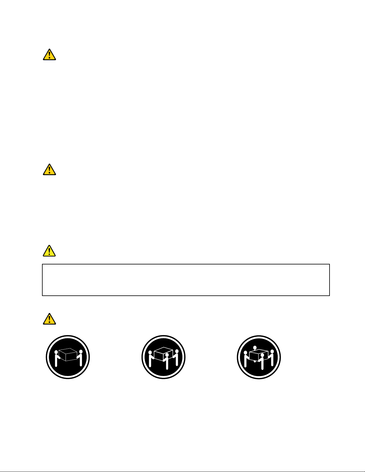
Statement4
≥18kg(39.7lb)≥32kg(70.5lb)≥55kg(121.2lb)
<32kg(70.5lb)<55kg(121.2lb)<100kg(220.5lb)
CAUTION:
Usesafepracticeswhenlifting.
©CopyrightLenovo2010,2011
v
Page 8
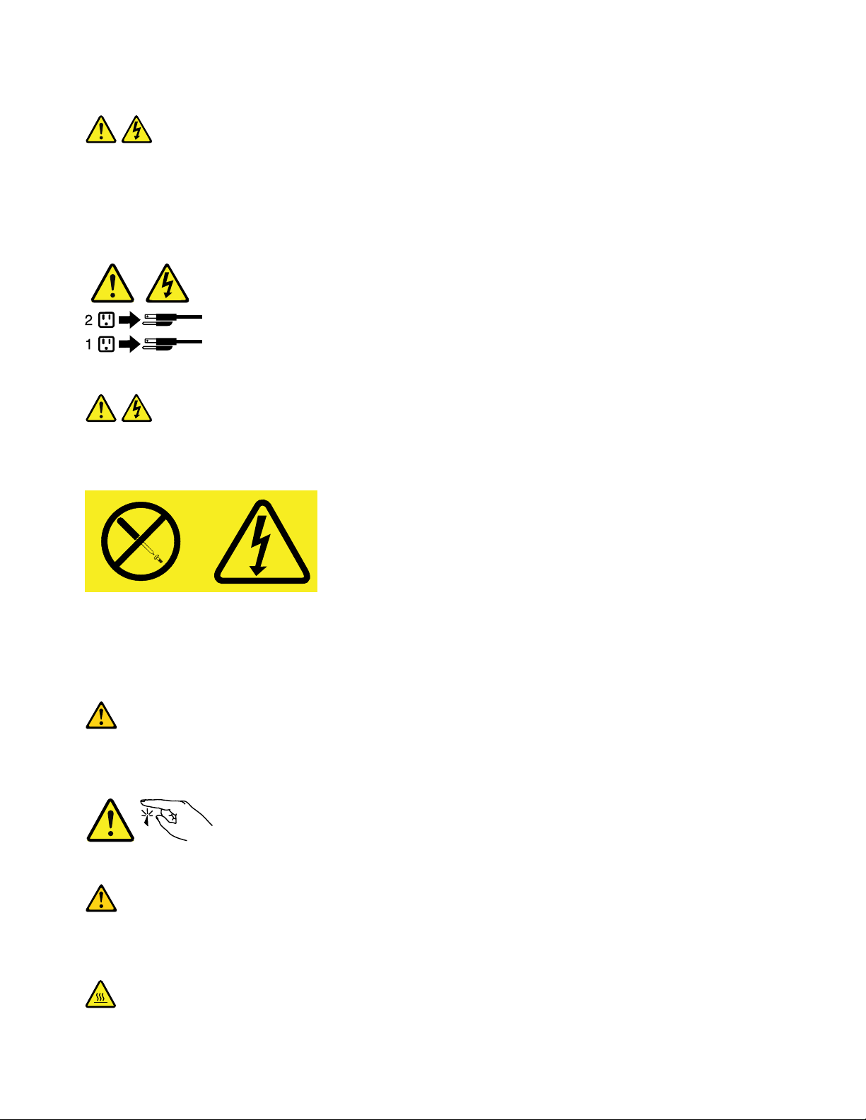
Statement5
CAUTION:
Thepowercontrolbuttononthedeviceandthepowerswitchonthepowersupplydonotturnoff
theelectricalcurrentsuppliedtothedevice.Thedevicealsomighthavemorethanonepower
cord.T oremoveallelectricalcurrentfromthedevice,ensurethatallpowercordsaredisconnected
fromthepowersource.
Statement8
CAUTION:
Neverremovethecoveronapowersupplyoranypartthathasthefollowinglabelattached.
Hazardousvoltage,current,andenergylevelsarepresentinsideanycomponentthathasthislabel
attached.Therearenoserviceablepartsinsidethesecomponents.Ifyoususpectaproblemwith
oneoftheseparts,contactaservicetechnician.
Statement11
CAUTION:
Thefollowinglabelindicatessharpedges,corners,orjointsnearby.
Statement12
CAUTION:
Thefollowinglabelindicatesahotsurfacenearby.
viThinkServerInstallationandUserGuide
Page 9
Statement13
DANGER
Overloadingabranchcircuitispotentiallyarehazardandashockhazardundercertain
conditions.T oavoidthesehazards,ensurethatyoursystemelectricalrequirementsdonotexceed
branchcircuitprotectionrequirements.Refertotheinformationthatisprovidedwithyourdevice
forelectricalspecications.
Statement15
CAUTION:
Makesurethattherackissecuredproperlytoavoidtippingwhentheserverunitisextended.
Statement17
CAUTION:
Thefollowinglabelindicatesmovingpartsnearby.
Statement26
CAUTION:
Donotplaceanyobjectontopofrack-mounteddevices.
©CopyrightLenovo2010,2011
vii
Page 10

viiiThinkServerInstallationandUserGuide
Page 11

Chapter1.Generalinformation
Thischapterprovidessomegeneralinformationaboutyourserver.
Thischaptercontainsthefollowingtopics:
•“Introduction”onpage1
•“Noticesandstatementsinthedocument”onpage1
•“Relateddocumentation”onpage2
Introduction
ThisInstallationandUserGuideisforyourLenovo®ThinkServer®RD240server(machinetypes1045,1046,
1047,and1048).Thisdocumentcontainsthefollowinginformation:
•Settingupandcablingtheserver
•Startingandconguringtheserver
•Installingoptionsandreplacingcustomerreplaceableunits(CRUs)
•Solvingproblems
TheservercomeswiththeThinkServerEasyStartupDVDtohelpyoucongurethehardware,installdevice
drivers,andinstalltheoperatingsystem.
Theservercomeswithalimitedwarranty.Forinformationaboutthetermsofthewarrantyandgetting
serviceandassistance,seetheWarrantyandSupportInformationonthedocumentationDVDthatcomes
withyourserver.
Toobtainthemostup-to-dateinformationabouttheserverandotherLenovoproducts,goto:
http://www.lenovo.com/thinkserver
Recordinformationabouttheserverinthefollowingtable.Y ouwillneedthisinformationwhenyouregister
theserverwithLenovo.
Productname
Machinetype1045,1046,1047,or1048
Modelnumber
Serialnumber
Themodelnumberandserialnumberareonthelabelsonthebottomoftheserverandonthefront,visible
throughthebezel.
ThinkServerRD240
_____________________________________________
_____________________________________________
Noticesandstatementsinthedocument
ThecautionanddangerstatementsthatappearinthisdocumentarealsointhemultilingualSafety
Information.Eachcautionanddangerstatementinthisdocumentislabeledwithanumber.Thisnumberis
usedtocrossreferenceanEnglish-languagecautionordangerstatementwithtranslatedversionsofthe
cautionordangerstatementintheSafetyInformation.See“Relateddocumentation”onpage2fordetailed
informationabouthowtogetthevariousdocumentationforyourserver.
©CopyrightLenovo2010,2011
1
Page 12
Thefollowingnoticesandstatementsareusedinthisdocument:
•Note:Thesenoticesprovideimportanttips,guidance,oradvice.
•Important:Thesenoticesprovideinformationoradvicethatmighthelpyouavoidproblemsor
inconvenientsituations.
•Attention:Thesenoticesindicatepotentialdamagetoprograms,devices,ordata.Anattentionnoticeis
placedjustbeforetheinstructionorsituationinwhichdamagecouldoccur.
•Caution:Thesestatementsindicatesituationsthatcanbepotentiallyhazardoustoyou.Acaution
statementisplacedjustbeforethedescriptionofapotentiallyhazardousproceduresteporsituation.
•Danger:Thesestatementsindicatesituationsthatcanbepotentiallylethalorextremelyhazardous
toyou.Adangerstatementisplacedjustbeforethedescriptionofapotentiallylethalorextremely
hazardousproceduresteporsituation.
Relateddocumentation
ThedocumentationDVDthatcomeswithyourservercontainsdocumentationfortheserverinPortable
DocumentFormat(PDF).ToviewthedocumentationontheDVD,youneedtohavetheAdobeReader
5.0programorlaterinstalled.
Thefollowingtableprovidesinformationaboutthegeneraldescriptionsofthevariousdocumentation
providedwithyourserverandhowtoobtainallthedocumentation.
Table1.Relateddocumentationfortheserver
DocumentationDescriptionLocation
HardwareMaintenance
Manual
ImportantNotices
RackInstallation
Instructions
ReadMeFirst
SafetyInformation
WarrantyandSupport
Information
Note:YoucanobtainallthedocumentationinPDFforyourserverfromtheLenovoSupportWebsiteat:
http://www.lenovo.com/support
Thisdocumentprovidesdiagnostic
information,partslisting,replacement
proceduresforallCRUs,andreplacement
proceduresforothereldreplaceableunits
(FRUs)replacedbytrainedservicepersonnel.
Thisdocumentincludessafetyandlegal
noticesthatyouareexpectedtoreadbefore
usingtheserver.
Thisdocumentprovidesinstructionsonhow
toinstallyourserverinarack.
ThisdocumentdirectsyoutotheThinkServer
DocumentationDVDforcompletewarranty
andsupportinformation.
Thisdocumentincludestranslationsofall
safetystatementsusedintheThinkServer
documentation.
Thisdocumentincludesthewarranty
statementandinformationabouthowto
contactLenovoSupport.
ThisdocumentisinEnglishandposted
ontheLenovoSupportWebsiteat
http://www.lenovo.com/support.
Thisdocumentisprintedoutand
providedinserverpackaging.
TheEnglishversionofthisdocument
isprintedoutandprovidedinthe
serverpackaging.Additionallanguages
areprovidedontheThinkServer
DocumentationDVDandontheLenovo
SupportWebsite:
http://www.lenovo.com/support
Thisdocumentisprintedoutand
providedinserverpackaging.
AvailableontheThinkServer
DocumentationDVD
AvailableontheThinkServer
DocumentationDVD
2ThinkServerInstallationandUserGuide
Page 13

Chapter2.Serversetuproadmap
Thischapterprovidesageneralroadmaptoguideyouthroughsettingupyourserver.
Theserversetupprocedurevariesdependingonthecongurationoftheserverwhenitwasdelivered.In
somecases,theserverisfullyconguredandyoujustneedtoconnecttheservertothenetworkandan
electricaloutlet,andthenyoucanturnontheserver.Inothercases,theserverneedstohavehardware
featuresinstalled,requireshardwareandrmwareconguration,andrequirestheoperatingsystemto
beinstalled.
Table2.Serversetuproadmap
TaskWheretondtheinformation
Unpack
Installhardware
InstalltheserverintherackTheRackInstallationInstructionsmanualisprintedandalsoincludedonthe
ConnecttheEthernetcable
andpowercord
Turnontheservertoverify
operation
ReviewtheBIOSsettings
andcustomizeasneeded
CongureRAID(onboard
SATARAIDortheinstalled
SASRAIDadapter)
Checkforrmwareupdates
Installoperatingsystemand
basicdrivers
Installanyadditionaldrivers
neededforaddedfeatures
CongureEthernetsettings
intheoperatingsystem
Installremotemanagement
applications
Installapplications
Chapter3“Featuresandtechnologies”onpage5
Chapter5“Installing,removing,orreplacinghardware”onpage17
ThinkServerDocumentationDVD.
“Rearview”onpage10
“Turningontheserver”onpage66
“StartingtheSetupUtilityprogram”onpage70
“RAIDcontrollers”onpage78
“UsingtheEasyUpdateFirmwareUpdaterprogram”onpage84
“UsingtheThinkServerEasyStartupprogram”onpage79
Refertotheinstructionsthatcamewiththehardwareoption.
Seetheoperatingsystemhelp.Thisstepisnotrequirediftheoperatingsystemwas
installedusingtheThinkServerEasyStartupprogram.
“InstallingtheThinkServerEasyManageprogram”onpage85
Refertothedocumentationthatcomeswiththeapplicationsthatyouwanttoinstall.
©CopyrightLenovo2010,2011
3
Page 14

4ThinkServerInstallationandUserGuide
Page 15

Chapter3.Featuresandtechnologies
Whatisincludedwithyourserver
TheRD240serverpackageincludestheserver,apowercord,documentation,theThinkServer
DocumentationDVD,andsoftwaremedia.
Features
TheRD240serveroffersthefollowingfeaturesandtechnologies:
•Microprocessor(s):TheserversupportsuptotwoIntel®Xeon®dual-core,quad-core,orhex-core
microprocessors.
•BIOS:Theserverrmwaredenesastandardinterfacebetweentheoperatingsystem,platformrmware,
andexternaldevices.
•EasyStartupDVD:TheThinkServerEasyStartupprogramguidesyouthroughthecongurationofthe
hardware,theRAIDcontroller,andtheinstallationoftheoperatingsystemanddevicedrivers.
•Integratednetworksupport:Theservercomeswithtwointegratedsingle-portGigabitEthernet
controllersandeachsupportsconnectiontoa10Mbps,100Mbps,or1000Mbpsnetwork.Formore
information,see“ConguringtheGigabitEthernetcontroller”onpage84.
•Largedata-storagecapacityandhot-swapcapability:Somehot-swapservermodelssupporteight
3.5-inchhot-swapharddiskdrives.Withthehot-swapfeature,youcanadd,remove,orreplaceharddisk
driveswithoutturningofftheserver.
•Largesystem-memorycapacity:Theserversupportsupto64GBofsystemmemory.Thememory
modulesupportserrorcorrectingcode(ECC)foruptoeightindustry-standardsingle-rankordual-rank,
1333MHz,DDR3(third-generationdouble-data-rate)registeredsynchronousdynamicrandomaccess
memory(SDRAM)dualinlinememorymodules(DIMMs).
•High-performancegraphicscontroller:Theservercomeswithanonboardhigh-performancegraphics
controllerthatsupportshighresolutionsandincludesmanyperformance-enhancingfeaturesforthe
operating-systemenvironment.
•Redundantconnection:
toaredundantEthernetconnection.IfaproblemoccurswiththeprimaryEthernetconnection,all
Ethernettrafcthatisassociatedwiththeprimaryconnectionisautomaticallyswitchedtotheredundant
NIC.Iftheapplicabledevicedriversareinstalled,thisswitchingoccurswithoutdatalossandwithout
userintervention.
•IntelligentPlatformManagementInterface(IPMI)2.0:Thecommand-lineinterfaceprovidesdirect
accesstoservermanagementfunctionsthroughtheIPMI2.0protocol.Usethecommand-lineinterface
toissuecommandstocontroltheserverpower,viewsysteminformation,andidentifytheserver.Y oucan
alsosaveoneormorecommandsasatextleandruntheleasascript.
•RAIDsupport:Theserversupportsanintegrated1068ESASRAIDcontrollerandanadd-onSASRAID
card(ThinkServer8708ELPSASRAIDAdapterorThinkServer8708EM2RAIDAdapter),whichare
requiredforyoutousethehot-swapSASorSATAharddiskdrivesandtocreatetheredundantarrayof
independentdisks(RAID)congurations.
Thetwoonboardnetworkinterfacecontrollers(NIC)provideafailovercapability
Specications
Thefollowinginformationisasummaryofthefeaturesandspecicationsoftheserver.Dependingonthe
servermodel,somefeaturesmightnotbeavailable,orsomespecicationsmightnotapply.
©CopyrightLenovo2010,2011
5
Page 16
Table3.Featuresandspecications
Microprocessor(s):Supportsupto
twoIntelXeondual-core,quad-core,
orhex-coremicroprocessors.Forthe
specictypeandspeedinformation
aboutthemicroprocessor,use
theSetupUtilityprogram.See
“UsingtheSetupUtilityprogram”on
page69
microprocessorsforyourserver,goto
http://www.lenovo.com/thinkserver.
OntheThinkServersystemspage,
clickProducts➙Options➙
ThinkServerProcessors.
Memorymodules:
•Minimumsystemmemory:2GB
•Maximumsystemmemory:64GB
•T ypes:ECC,1333MHz,DDR3
•Slots:Eightdualinlinememory
•Supports2GB,4GB,and8GB
Integratedgraphicscard:
•8MBvideomemory
Size:
•Height:87.5mm(3.45inches)
•Width:448mm(17.64inches)
•Depth:683mm(26.89inches)
•
.Foralistofthesupported
(eightmemoryslots,eachwithone
8GBRDIMMinstalled)
registeredSDRAMDIMMsonly
module(DIMM)slots
RDIMMs
Maximumweight:30kg(66.14lb)
whenfullycongured
Opticaldrive:
•SlimDVD/RW
Harddiskdriveexpansionbays
(dependingonthemodel):
Uptoeight3.5-inchSATAorSAS
harddiskdrives
Expansionslots:
•OnePCIExpressx16cardsloton
thesystemboardforarisercard
(therearethreePCIExpressx8
cardslotsontherisercard)
Powersupply:750-wattsingle
powersupply/750-wattredundant
powersupply
Systemfans:Foursystemfans
withautomaticenergy-saving,noise
reductiontechnology
Integratedfunctions:
•T wosingle-portGbEthernet
controllers
•SixUSB2.0connectors(twofront
andfourrear)
•T woRJ-45Ethernetconnectors
•Oneserialport
•OneVideoGraphicsArray(VGA)
monitorconnector
Environment:
•Airtemperature:
–Serveron:10°Cto35°C(50°F
to95°F);altitude:0to914.4m
(3000ft)
–Serveroff:10°Cto43°C(50°F
to109.4°F);maximumaltitude:
2133.6m(7000ft)
–Shipping:-40°Cto60°C(-104°F
to140°F)
•Humidity:
–Serveron:upto80%,
non-condensing
–Serveroff:upto80%,
non-condensing
–Shippingandstorage:upto
93%,non-condensing
•Particulatecontamination:
Attention:Airborneparticulates
andreactivegasesactingalone
orincombinationwithother
environmentalfactorssuchas
humidityortemperaturemight
posearisktotheserver.
6ThinkServerInstallationandUserGuide
Page 17
Table3.Featuresandspecications(continued)
RAIDadapters:
•Onboard1068ESASRAIDadapter
•ThinkServer8708ELPSASRAID
Adapter
•ThinkServer8708EM2RAID
Adapter
Electricalinput
•Inputvoltage:
–Lowrange:
–Highrange:
Minimum:100Vac
Maximum:127Vac
Inputfrequencyrange:50to
60Hz
Minimum:200Vac
Maximum:240Vac
Inputfrequencyrange:50to
60Hz
Notes:
1.Powerconsumptionandheat
outputvarydependingonthe
numberandtypeofoptional
featuresinstalledandthe
power-managementoptional
featuresinuse.
2.Thesoundlevelsweremeasured
incontrolledacoustical
environmentsaccordingto
theproceduresspeciedbythe
AmericanNationalStandards
Institute(ANSI)S12.10and
ISO7779andarereportedin
accordancewithISO9296.
Actualsound-pressurelevelsina
givenlocationmightexceedthe
averagevaluesstatedbecause
ofroomreectionsandother
nearbynoisesources.The
noiseemissionlevelstated
isthedeclared(upperlimit)
sound-powerlevel,inbels,fora
randomsampleofsystem.
3.Thereisnokeyboardconnector
ormouseconnectoronthe
server.Y oucanconnectaUSB
keyboardandUSBmouseto
theserverbyusingtheUSB
connectors.
Softwareprograms
Lenovoprovidessoftwaretohelpgetyourserverupandrunning.
EasyStartup
TheThinkServerEasyStartupprogramsimpliestheprocessofconguringRAIDandinstallingsupported
Microsoft®Windows®andLinuxoperatingsystemsanddevicedriversonyourserver.TheEasyStartup
programisprovidedwithyourserverontheThinkServerEasyStartupDVD.TheDVDisself-starting
(bootable).TheuserguidefortheEasyStartupprogramisontheDVDandcanbeaccesseddirectlyfromthe
programinterface.Foradditionalinformation,see“UsingtheThinkServerEasyStartupprogram”onpage79
EasyManage
TheThinkServerEasyManageAgentenablesthisservertobemanagedbythecentralizedconsoleofan
EasyManageCoreServeroverthenetwork.TheThinkServerEasyManageAgentissupportedon32-bitand
64-bitWindows,RedHat,andSUSEoperatingsystems.
Reliability,availability,andserviceability
Reliability,availability,andserviceability(hereafterreferredtoasRAS)arethreeimportantserverdesign
features.TheRASfeatureshelpyoutoensuretheintegrityofthedatastoredontheserver,theavailabilityof
theserverwhenyouneedit,andtheeasewithwhichyoucandiagnoseandcorrectproblems.
.
Chapter3.Featuresandtechnologies7
Page 18

TheserverhasthefollowingRASfeatures:
•AdvancedCongurationandPowerInterface(ACPI)
•AdvancedDesktopManagementInterface(DMI)
•Automaticmemorydownsizingonerrordetection
•Automaticrestartonnon-maskableinterrupt(NMI)
•Availabilityofmicrocodelevel
•Built-in,menu-drivensetup,systemconguration,andRAIDconguration
•Built-inmonitoringforfan,temperature,andvoltage
•Coolingfanswithspeed-sensingcapability
•ECCDDR3SDRAMwithSerialPresenceDetect(SPD)
•Errorcodesandmessagestohelpyouidentifyproblems
•Generatingerrorlogsforthepower-onself-test(POST)failures
•Hot-swapSASharddiskdrives
•IntegratedEthernetcontrollers
•IntelligentPlatformManagementInterface(IPMI)2.0
•Power-onself-test(POST)
•RedundantEthernetconnectionwithfailovercapability(requiresanoptionalEthernetcard)
•Standbyvoltageforsystem-managementfeaturesandmonitoring
•System-errorlight-emittingdiode(LED)onthefrontpanel
•Vitalproductdata(VPD),includingtheserialnumberinformationandreplacementpartnumbers,storedin
thenonvolatilememoryforeasierremotemaintenance
8ThinkServerInstallationandUserGuide
Page 19
Chapter4.Locatingparts,controls,LEDs,andconnectors
Thischapterprovidesinformationtohelpyoulocateyourserverparts,controls,light-emittingdiodes
(LEDs),andconnectors.
Frontview
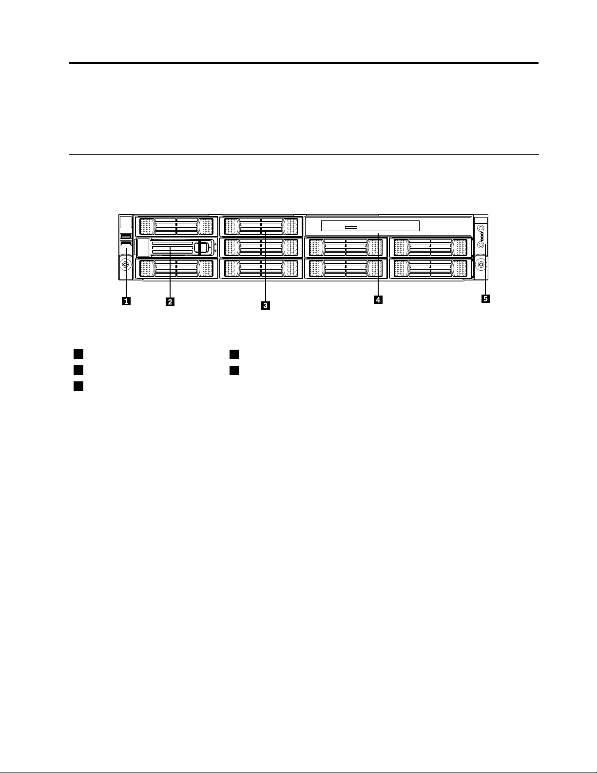
Thefollowingillustrationshowsthedrivesandpartsonthefrontoftheserver.
Figure1.Frontviewoftheserverwitheightharddiskdrivesandanopticaldrive
1Lefthandleofthechassis
23.5-inchharddiskdrivebay
33.5-inchharddiskdrivedummy
bay
4Opticaldrive
5Frontcontrolpanel(see“Frontcontrolpanel”onpage11)
©CopyrightLenovo2010,2011
9
Page 20
Rearview
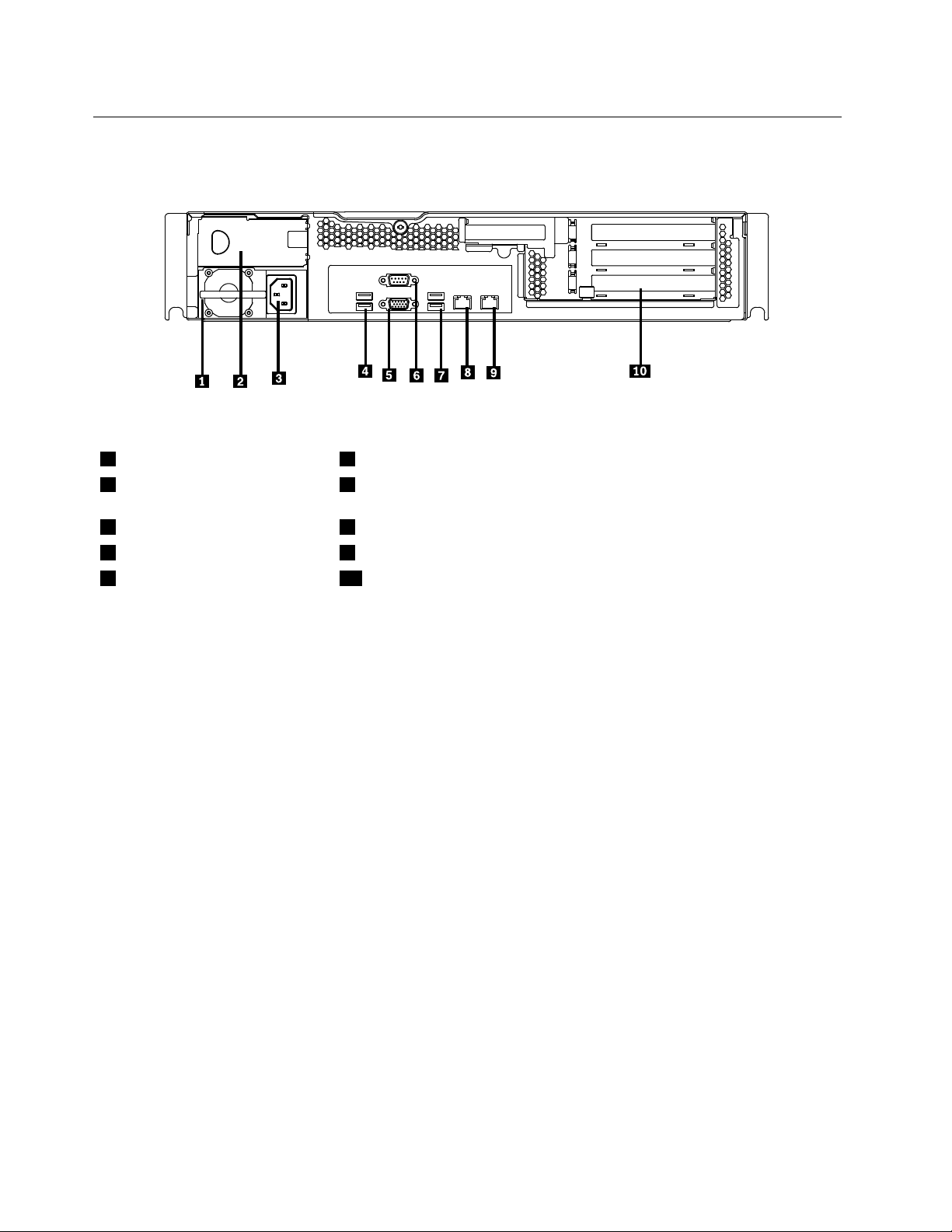
Thefollowingillustrationshowsthelocationsoftheconnectorsandpartsontherearoftheserver.
Figure2.Rearviewoftheserver
1Powersupply1
2Powersupply2bay(blankand
6Serialport
7USBconnectors(3and4)
coveredbyabaybezel)
3Powercordconnector8Ethernetconnector1
4USBconnectors(1and2)9Ethernetconnector2(sharewithMGMT)
5VGAmonitorconnector10PCIexpansionslot
ConnectorDescription
PowercordconnectorUsedtoconnectthepowercord.
Ethernetconnector
Serialport
UsedtoattachanEthernetcableforalocalareanetwork(LAN).
Usedtoattachadevicethatusesa9-pinserialport.
USBconnectorUsedtoattachadevicethatusesaUSBconnector,suchasaUSBkeyboard
oraUSBmouse.
VGAmonitorconnectorUsedtoattachaVGAmonitororotherdevicesthatuseaVGAmonitorconnector.
10ThinkServerInstallationandUserGuide
Page 21
Frontcontrolpanel
Thissectionprovidesinformationaboutthefrontcontrolpaneloftheserver.
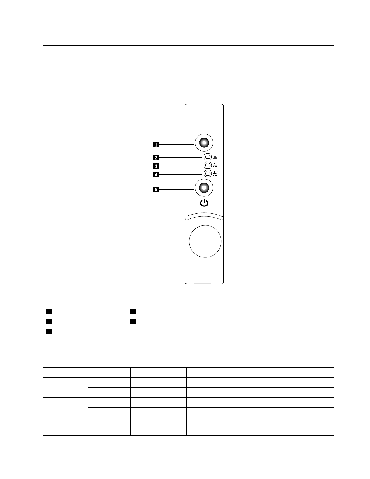
Thefollowingillustrationhelpsyouidentifytheconnectors,controls,andLEDsonthefrontcontrolpanelof
yourserver.
Figure3.Frontcontrolpanel
1IDbuttonandLED4Ethernet2statusLED
2SystemstatusLED
3Ethernet1statusLED
5PowerbuttonandLED
ThefollowingtabledescribesthemeaningoftheLEDsonthefrontcontrolpanel.
Table4.FrontcontrolpanelLEDs
LEDStateColorDescription
On
OffOff
OffOffSystemisnormal. Systemstatus
LED
On
BlueIDison. IDLED
IDisoff.
Red•Fanalarm
•Voltagealarm
•T emperaturealarm
Chapter4.Locatingparts,controls,LEDs,andconnectors11
Page 22
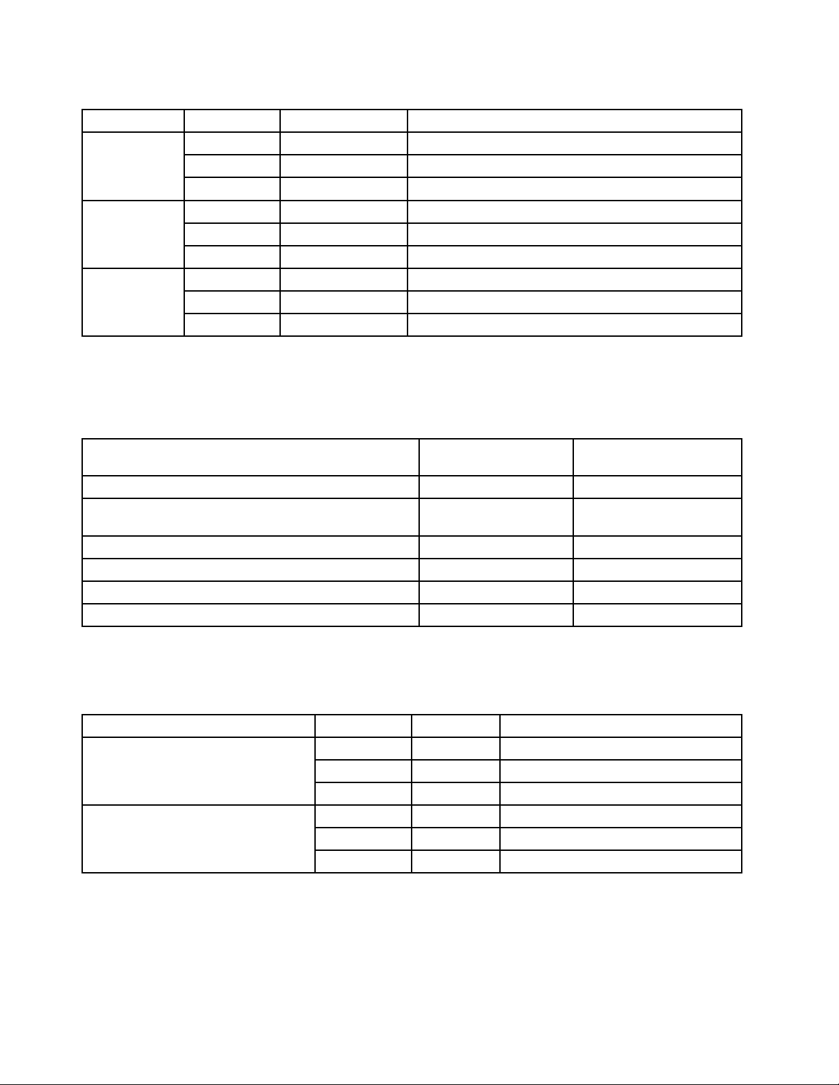
Table4.FrontcontrolpanelLEDs(continued)
LEDStateColorDescription
Ethernet1
statusLED
Ethernet2
statusLED
Powerstatus
LED
Blinking
OnGreen
OffOff
Blinking
OnGreen
OffOff
OnGreen
Blinking
OffOff
Green
Green
GreenTheserverpowerisunderS1mode.
LANisactiveanddataisbeingtransferred.
LANisconnected.
LANisnotconnected.
LANisactiveanddataisbeingtransferred.
LANisconnected.
LANisnotconnected.
Powerison.
Powerisoff.
EachharddiskdrivealsohastwostatusLEDs.StatusLED1(top)indicatespresence(whetherthedriveis
recognizedbythesystem)andStatusLED2(bottom)indicatesdriveactivity.
Table5.HarddiskdrivestatusLEDsfortheonboard1068ESASRAIDadapterandadd-onSASRAIDadapter
congurations
Harddiskdrivestatus
Description
Harddiskdriveisnotpresent.
Harddiskdriveispresentbutisnotactive.
Harddiskdriveispresentandactive.
Serverisintheprocessoflocatingtheharddiskdrive.
Harddiskdrivehasfailed.
RAIDisrebuilding.Blinkingred
OffOff
OffGreen(forSATAharddisk
Off
Blinkinggreen
Red
LED1
Harddiskdrivestatus
LED2
drives,thestatusisOff)
Blinkinggreen
Green
Green
Green
TheEthernet1andEthernet2connectorshavetwostatusLEDsthatindicatetheLANconnectionand
activityoftheconnection.
Table6.EthernetLEDs
LEDStateColorDescription
RJ-45linkage/activity(left)
RJ-45speed(right)
OnGreen10/100/1000Mblinked
Blinking
OffOff
On
OnGreen
OffOff
Green10/100/1000Mbactivity
NoLANconnection.
Amber1000Mblinkedandactive
100Mblinkedandactive
10MbmodeornoLANconnection.
12ThinkServerInstallationandUserGuide
Page 23
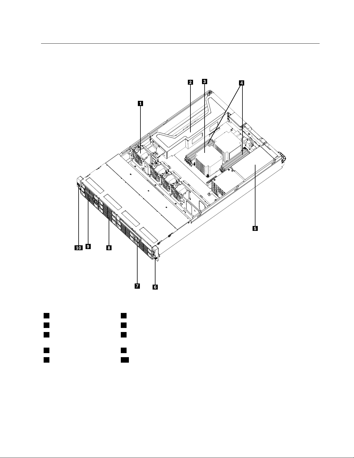
Locatingservercomponents
Thefollowingillustrationshowsthelocationsofthemajorcomponentsinyourserver.
Figure4.Servercomponentlocations
1Systemfans6Frontcontrolpanel(see“Frontcontrolpanel”onpage11)
2Risercardassembly
3Microprocessorandheat
7Opticaldrive(dependingonthemodel)
83.5-inchharddiskdrivedummybay
sink
4Memorymodules93.5-inchharddiskdrive
5Powersupplyassembly
10Lefthandleofthechassis
Chapter4.Locatingparts,controls,LEDs,andconnectors13
Page 24
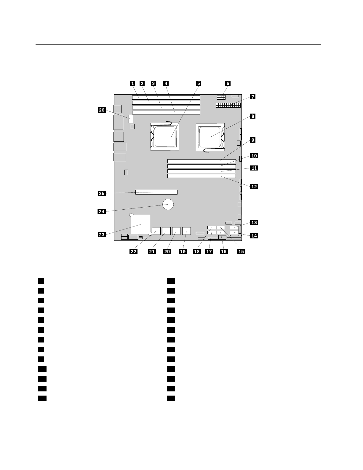
Locatingpartsonthesystemboard
Thefollowingillustrationsshowthelocationsofthepartsonthesystemboard.
Figure5.Locatingmajorpartsonthesystemboard
1Memoryslot(CPU1DIMMCHC0)14SATAconnector1
2Memoryslot(CPU1DIMMCHB0)15SATAconnector2
3Memoryslot(CPU1DIMMCHA0)16SA TAconnector3
4Memoryslot(CPU1DIMMCHA1)17SA TAconnector5
5Microprocessor(CPU1)18SATAconnector4
6Powerconnector2(forCPU0)19SASconnectors(top:SAS1;bottom:SAS0)
724-pinpowerconnectorforthesystemboard
8Microprocessor(CPU0)21SASconnectors(top:SAS5;bottom:SAS4)
9Memoryslot(CPU0DIMMCHA1)22SASconnectors(top:SAS7;bottom:SAS6)
10Memoryslot(CPU0DIMMCHA0)23Onboard1068ESASRAIDcontroller
11Memoryslot(CPU0DIMMCHB0)24Systemboardbattery
12Memoryslot(CPU0DIMMCHC0)25PCIExpressx16cardslot(forarisercard)
13SATAconnector026Powerconnector3(forCPU1)
20SASconnectors(top:SAS3;bottom:SAS2)
14ThinkServerInstallationandUserGuide
Page 25
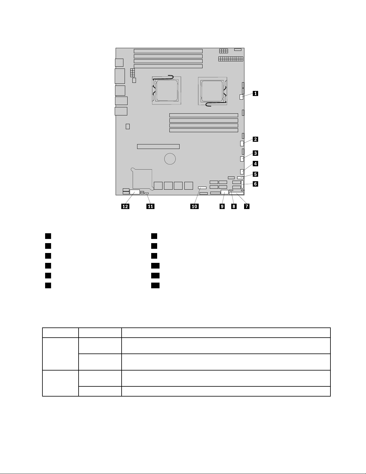
Figure6.Locatingotherconnectorsonthesystemboard
1Systemfan1connector7J35(forfrontcontrolcable)
2Systemfan2connector8JP1(clearCMOS)
3Systemfan3connector9USB2connector
4Systemfan4connector10J21(SGPIOconnectorforonboardSASport5-8)
5FrontUSBconnector11JP7(setonboardSAS)
6J51(SGPIOconnectorforonboard
12J16(COM2connector)
SASport1-4)
Thefollowingtableintroducesthejumperswitchesonthesystemboard.
Table7.Jumpersettings
JumperPositionDescription
JP1:Clear
CMOS
JP7:Set
Onboard
SAS
Pins1-2
Pins2-3
Pins1-2
Pins2-3
Thedefaultpositionatwhichthejumperisplacedonpins1-2duringthenormal
operationofthesystem.
Ifthejumperisplacedonpins2-3,whenthejumperismovedbacktothedefault
positionsandatthenextstartup,thesettingsofCMOSwillbeclearedautomatically.
Thedefaultpositionatwhichthejumperisplacedonpins1-2duringthenormal
operationofthesystem.TheonboardSAScontrollerisEnabled.
Ifthejumperisplacedonpins2-3,theonboardSAScontrollerisDisabled.
Note:BeforeclearingtheCMOS,turnofftheserveranddisconnectthepowercord.Movethejumperfrom
pins1-2topins2-3.Waitmorethanveminutesandthenmovethejumperbacktothenormalposition
(pins1-2)toclearCMOS.
Chapter4.Locatingparts,controls,LEDs,andconnectors15
Page 26
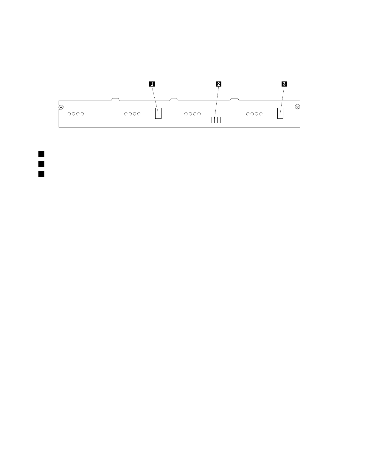
Locatingconnectorsonthebackplane
Thefollowingillustrationshowstheconnectorlocationsonthebackplane.
Figure7.Backplaneconnectorlocations
1MiniSASsignalconnector2
2Powerconnector
3MiniSASsignalconnector1
16ThinkServerInstallationandUserGuide
Page 27

Chapter5.Installing,removing,orreplacinghardware
Thischapterprovidesinstructionsonhowtoinstall,remove,orreplacehardwareforyourserver.
Thischaptercontainsthefollowingtopics:
•“Guidelines”onpage17
•“Removingtheservercover”onpage19
•“Installing,removing,orreplacingoptionalhardwaredevices”onpage20
•“Installing,removing,orreplacinghardwaredevices”onpage38
•“Completingthepartsreplacement”onpage65
Guidelines
Thissectionprovidessomeguidelinesthatyoushouldreadandunderstandbeforeusingyourserver.
Basicguidelines
Beforeyouusetheserver,besuretoreadandunderstandthefollowingguidelines:
•BesuretoreadandunderstandtheSafetyInformationandtheWarrantyandSupportInformationonthe
documentationDVDthatcomeswithyourproduct,and“Guidelines”onpage17
helpyouworksafely.T oobtainacopyofthepublications,goto:
http://www.lenovo.com/support
•Whenyouinstallyournewserver,taketheopportunitytodownloadandapplythemostrecentrmware
updates.Thisstepwillhelpyoutoensurethatanyknownissuesareaddressedandtheserverisreadyto
functionatoptimalperformance.Todownloadrmwareupdatesforyourserver,dothefollowing:
1.Gotohttp://www.lenovo.com/support.
2.ClickDownload&Drivers➙ThinkServerandthenfollowtheinstructionsontheWebpageto
downloadrmwareupdatesforyourserver.
•Observegoodhousekeepingintheareawhereyouareworking.Putremovedcoversandotherparts
inasafeplace.
•Ifyoumustturnontheserverwhiletheservercoverisremoved,makesurethatnooneisneartheserver
andthatnotoolsorotherobjectshavebeenleftinsidetheserver.
•Donotattempttoliftanobjectthatyouthinkistooheavyforyou.Ifyouhavetoliftaheavyobject,
observethefollowingprecautions:
.Theseinformationwill
–Makesurethatyoucanstandsafelywithoutslipping.
–Distributetheweightoftheobjectequallybetweenyourfeet.
–Useaslowliftingforce.Nevermovesuddenlyortwistwhenyouliftaheavyobject.
–Toavoidstrainingthemusclesinyourback,liftbystandingorbypushingupwithyourlegmuscles.
•Makesurethatyouhaveanadequatenumberofproperlygroundedelectricaloutletsfortheserver,
monitor,andotherdevices.
•Backupallimportantdatabeforeyoumakechangestodrives.
•Haveasmallat-bladescrewdriveravailable.
•ToviewtheerrorLEDsonthesystemboardandinternalcomponents,leavetheserverconnectedto
power.
©CopyrightLenovo2010,2011
17
Page 28
•Y oudonothavetoturnofftheservertoinstallorreplacehot-swapfans,redundanthot-swapacpower
supplies,orhot-plugUSBdevices.However,youmustturnofftheserverbeforeperforminganystepsthat
involveinstalling,removing,orreplacingadaptercablesornon-hot-swapoptionaldevicesorcomponents.
•Aftercompletinganyinstallation,removal,orreplacementprocedure,reinstallallsafetyshields,guards,
labels,andgroundwires.
•Foralistofsupportedoptionaldevicesfortheserver,gotohttp://www.lenovo.com/thinkserver.
•Whenworkinginsidetheserver,youmightndsometaskseasierifyoulaytheserveronitsside.
Systemreliabilityguidelines
Tohelpensurepropercoolingandsystemreliability,makesurethatyoufollowtheseguidelines:
•EverydrivebayhasaninternaldriveinstalledoranElectroMagneticCompatibility(EMC)shieldinstalled.
•Iftheserverhasredundantpower,everypowersupplybayhasapowersupplyassemblyinstalled.
•Leaveadequatespacearoundtheservertomakesurethattheservercoolingsystemworkswell.
•Properlyroutethecables.Forsomeoptions,suchasPCIcards,followthecablinginstructionsthat
comewiththeoptions.
•Makesurethatyoureplaceafailingfanwithin48hours.
•Whenreplacingahot-swapdrive,installthenewhot-swapdrivewithintwominutesofremoval.
•Donotremoveanyairductorairbafeswhiletheserverisrunning.Operatingtheserverwithoutthe
airductorairbafesmightcausethemicroprocessortooverheat.
•Thesecondmicroprocessorsocketalwayscontainseitheramicroprocessorsocketcoverora
microprocessor.
Handlingstatic-sensitivedevices
Attention:
Donotopenthestatic-protectivepackagecontainingthenewpartuntilthedefectiveparthasbeenremovedfromthe
serverandyouarereadytoinstallthenewpart.Staticelectricity,althoughharmlesstoyou,canseriouslydamage
servercomponentsandparts.
Whenyouhandleserverpartsandcomponents,taketheseprecautionstoavoidstatic-electricitydamage:
•Limityourmovement.Movementcancausestaticelectricitytobuilduparoundyou.
•Wearanelectrostatic-dischargewriststrap,ifoneisavailable.
•Alwayscarefullyhandlethepartsandothercomponents(suchasPCIcards,memorymodules,system
boards,andmicroprocessors)byitsedgesoritsframe.Donottouchsolderjoints,pins,orexposed
circuitry.
•Preventothersfromtouchingthepartsandothercomputercomponents.
•Beforeyoureplaceanewpart,touchthestatic-protectivepackagecontainingthenewparttoametal
expansion-slotcoverorotherunpaintedmetalsurfaceontheserverforatleasttwoseconds.This
reducesstaticelectricityfromthepackageandyourbody.
•Removethenewpartfromthestatic-protectivepackageanddirectlyinstallitintheserverwithout
placingitonanyothersurface.Ifitishardforyoutodothisinyourspecicsituation,placethe
static-protectivepackageofthenewpartonasmooth,levelsurface,andthenplacethenewparton
thestatic-protectivepackage.
•Donotplacethepartontheservercoverorothermetalsurface.
•Takeadditionalcarewhenhandlingdevicesduringcoldweather.Heatingreducesindoorhumidity
andincreasesstaticelectricity.
18ThinkServerInstallationandUserGuide
Page 29

Workinginsidetheserverwiththepoweron
Attention:
Staticelectricitythatisreleasedtointernalservercomponentswhentheserveristurnedonmightcausetheserverto
halt,whichmightresultinthelossofdata.Toavoidthispotentialproblem,alwaysuseanelectrostatic-dischargewrist
straporothergroundingsystemwhenyouworkinsidetheserverwiththepoweron.
Theserversupportshot-swapdevicesandisdesignedtooperatesafelywhileitisturnedonandthecoveris
removed.Followtheseguidelineswhenyouworkinsidetheserverwiththepoweron:
•Avoidwearingloose-ttingclothingonyourforearms.Buttonlong-sleevedshirtsbeforeworkinginside
theserver;donotwearcufflinkswhileyouareworkinginsidetheserver.
•Donotallowyournecktieorscarftohanginsidetheserver.
•Removejewelry,suchasbracelets,necklaces,rings,andloose-ttingwristwatches.
•Removeitemsfromyourshirtpocket,suchaspensandpencils.Theseitemsmightfallintotheserveras
youleanoverit.
•Avoiddroppinganymetallicobjectsintotheserver,suchaspaperclips,hairpins,andscrews.
Removingtheservercover
Attention:Donotopenyourserverorattemptanyrepairbeforereadingandunderstandingthe“Safetyinformation”
onpageiiiand“Guidelines”onpage17.
Thissectionprovidesinstructionsonhowtoremovetheservercover.
Toremovetheservercover,dothefollowing:
1.Removeallmediafromthedrives.Then,turnoffallattacheddevicesandtheserver.
2.Disconnectallpowercordsfromelectricaloutlets.
3.Disconnectthepowercord(s),Input/Output(I/O)cables,andallothercablesthatareconnectedto
theserver.
Chapter5.Installing,removing,orreplacinghardware19
Page 30
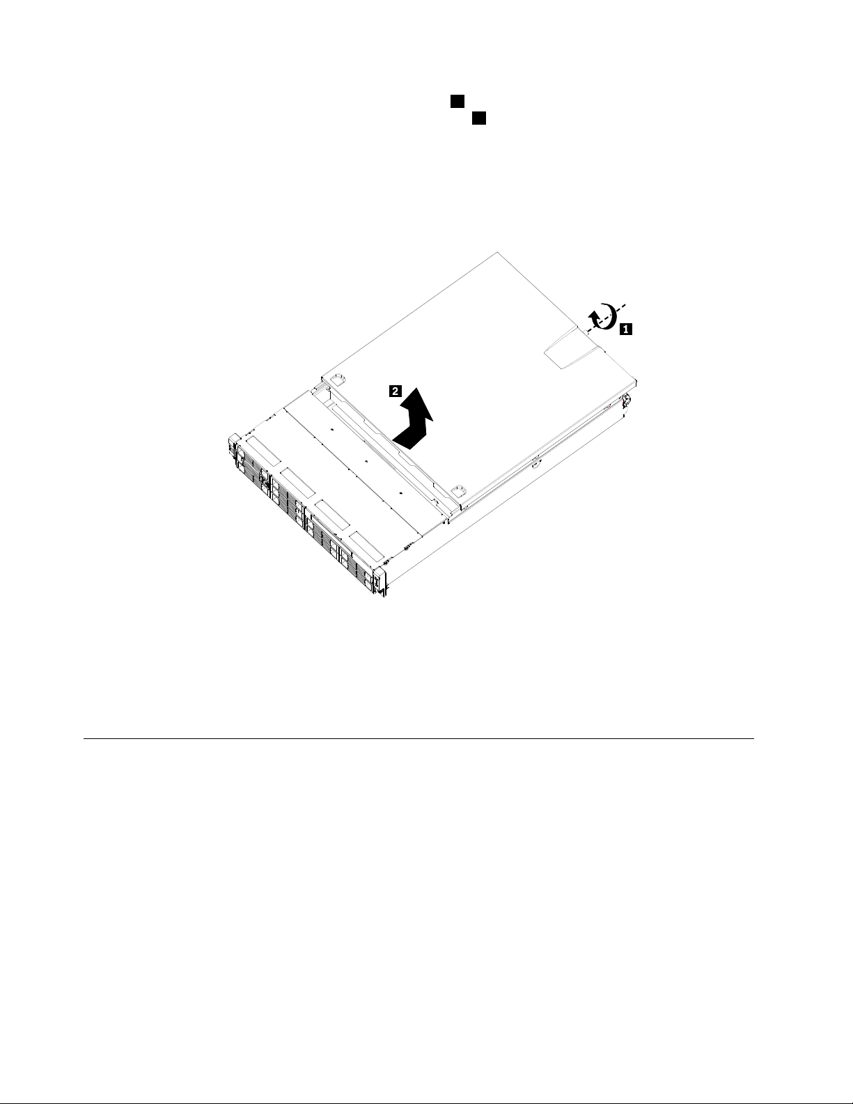
4.Loosenthethumbscrewintherearoftheservercover1.Then,slidetheservercovertotherearuntil
youcanliftituptocompletelyremoveitfromthechassis2.
Notes:
a.Thethumbscrewissecurelyinstalledandyouneedtouseatool,suchasascrewdriver,toloosenit.
b.Thethumbscrewisanintegratedpartoftheservercoveranditcannotberemovedfromtheserver
cover.
Figure8.Removingtheservercover
Attention:Forpropercoolingandairow,installtheservercoverbeforeturningontheserver.Operatingthe
serverformorethan30minuteswiththeservercoverremovedmightdamageservercomponents.
Toreinstalltheservercover,see“Installingtheservercover”onpage65.
Installing,removing,orreplacingoptionalhardwaredevices
Thissectionprovidesinstructionsonhowtoinstall,remove,orreplaceoptionalhardwaredevicesforyour
server.Youcanexpandthecapabilitiesofyourserverbyaddingmemorymodules,PCIcards,ordrives,
andmaintainyourserverbyreplacingthefailingoptionalhardwaredevices.Ifyouarereplacinganoptional
hardwaredevice,performtheremovalprocedureandthenperformtheinstallationprocedurefortheoptional
hardwaredevicethatyouwanttoreplace.
Installingorremovingamemorymodule
Thissectionprovidesinstructionsonhowtoinstallorremoveamemorymodule.Foralistofthesupported
memorymodulesforyourserver,gotohttp://www.lenovo.com/thinkserver.OntheThinkServersystems
page,clickProducts➙Options➙ThinkServerMemory.
20ThinkServerInstallationandUserGuide
Page 31

Memorymoduleinstallationrules
YourserverhaseightmemoryslotsforinstallingorreplacingDDR3SDRAMDIMMsthatprovideuptoa
maximumof64GBofsystemmemory.
Thefollowingtablesprovideinformationaboutthememorymoduleinstallationrulesthatyoushould
considerwheninstallingamemorymodule.The“X”markindicatesthesuggestedmemoryslot(s)into
whichthememorymodule(s)shouldbeinstalledindifferentsituations.Thenumber,forexample1,2,or3,
indicatestheinstallationsequence.See“Locatingpartsonthesystemboard”onpage14
variousmemoryslots.
Note:Allmemorymoduletypesandcapacitiesmustbeconsistent.
Table8.DIMMinstallationruleswhenasinglemicroprocessor(CPU0)isinstalled
DIMMslotOneDIMMTwoDIMMsThreeDIMMsFourDIMMs
CPU0DIMMCHA1
CPU0DIMMCHA0
CPU0DIMMCHB0
CPU0DIMMCHC0
Note:InstallingDIMMsonchannelAandchannelBofCPU0shouldenableChannelMirroringMode.Thismode
requiresthatyouinstalltheDIMMsinpair,andtheDIMMinstallationforChannelMirroringModeisoneDIMMon
CPU0DIMMCHA0andoneDIMMonCPU0DIMMCHB0whenasinglemicroprocessor(CPU0)isinstalled.
XX,1X,1X,1
X,2X,2X,2
X,3X,3
toidentifythe
X,4
Table9.DIMMinstallationruleswhentwomicroprocessors(CPU0andCPU1)areinstalled
DIMMslotTwoDIMMsFourDIMMsSixDIMMsEightDIMMs
CPU0DIMMCHA1
CPU0DIMMCHA0
CPU0DIMMCHB0
CPU0DIMMCHC0
CPU1DIMMCHA1
CPU1DIMMCHA0
CPU1DIMMCHB0
CPU1DIMMCHC0
Note:FortheChannelMirroringMode,itrequiresthatyouinstalltheDIMMsinpair,andtheDIMMinstallationfor
ChannelMirroringModewhentwomicroprocessors(CPU0andCPU1)areinstalledisshownbelow.Followthis
sequenceratherthanthesequencelistedaboveifyouwanttousetheChannelMirroringMode.
1.Pair1:installaDIMMonCPU0DIMMCHA0andtheninstallaDIMMonCPU0DIMMCHB0.
2.Pair2:installaDIMMonCPU1DIMMCHA0andtheninstallaDIMMonCPU1DIMMCHB0.
X,1X,1X,1X,1
X,3X,3X,3
X,5X,5
X,2X,2X,2X,2
X,4X,4X,4
X,6X,6
Installingamemorymodule
Attention:Donotopenyourserverorattemptanyrepairbeforereadingandunderstandingthe“Safetyinformation”
onpageiiiand“Guidelines”onpage17.
X,7
X,8
Thissectionprovidesinstructionsonhowtoinstallamemorymodule.
Toinstallamemorymodule,dothefollowing:
1.Removeallmediafromthedrivesandturnoffallattacheddevicesandtheserver.Then,disconnectall
powercordsfromelectricaloutletsanddisconnectallcablesthatareconnectedtotheserver.
Chapter5.Installing,removing,orreplacinghardware21
Page 32

2.Removetheservercover.See“Removingtheservercover”onpage19.
3.Locatetheappropriatememoryslotonthesystemboardintowhichyouwillinstallthememorymodule.
Tooptimizesystemperformance,followtherelatedmemorymoduleinstallationrulesandinstallthe
memorymoduleintoamemoryslotstartingwiththememorymodulefarthestfromthemicroprocessor.
See“Memorymoduleinstallationrules”onpage21.
4.Opentheretainingclipsofthememoryslotintowhichyouwanttoinstallthememorymodule.
Figure9.Openingtheretainingclipsofthememoryslot
5.T ouchthestatic-protectivepackagethatcontainsthenewmemorymoduletoanyunpaintedmetal
surfaceontheoutsideoftheserver.Then,removethenewmemorymodulefromthepackage.
6.Positionthenewmemorymoduleoverthememoryslot.Makesurethatthenotch1onthenewmemory
moduleisalignedwiththekey
2inthememoryslot.Then,pressthenewmemorymodulestraightdown
intothememoryslotuntiltheretainingclipscloseandthenewmemorymodulesnapsintoposition.
Note:Ifthereisagapbetweenthememorymoduleandtheretainingclips,thememorymodulehas
notbeencorrectlyinstalled.Opentheretainingclips,removethememorymodule,andthenreinstallit
intotheslot.
Figure10.Installingthememorymodule
Whattodonext:
•Toworkwithanotherpieceofhardware,gototheappropriatesection.
•Tocompletetheinstallation,goto“Completingthepartsreplacement”onpage65.
22ThinkServerInstallationandUserGuide
Page 33

Removingamemorymodule
Attention:Donotopenyourserverorattemptanyrepairbeforereadingandunderstandingthe“Safetyinformation”
onpageiiiand“Guidelines”onpage17.
Thissectionprovidesinstructionsonhowtoremoveamemorymodule.
Toremoveamemorymodule,dothefollowing:
1.Removeallmediafromthedrivesandturnoffallattacheddevicesandtheserver.Then,disconnectall
powercordsfromelectricaloutletsanddisconnectallcablesthatareconnectedtotheserver.
2.Removetheservercover.See“Removingtheservercover”onpage19.
3.Locatethememoryslotwiththememorymodulethatyouwanttoremove.See“Locatingpartsonthe
systemboard”onpage14
4.Carefullyopentheretainingclipsoneachendofthememoryslotandthengraspthememorymodule
straightupbyitsedges.
forthelocationsofthememoryslots.
Figure11.Removingthememorymodule
5.Ifyouareinstructedtoreturnthefailingmemorymodule,followallpackaginginstructionsanduseany
packagingmaterialsthataresuppliedtoyouforshipping.
Whattodonext:
•Toworkwithanotherpieceofhardware,gototheappropriatesection.
•Tocompletetheremovalprocedure,goto“Completingthepartsreplacement”onpage65.
Removingorinstallinginternaldrives
Thissectionprovidesinstructionsonhowtoremoveorinstallinternaldrivesfortheserver.
See“Specications”onpage5forinformationaboutthetypesofinternaldrivesthattheserversupportsand
otherimportantinformation,andsee“Frontview”onpage9forthelocationsofthedrivebaysintheserver.
Wheninstallinganinternaldrive,besuretoconsiderthefollowinginformation:
•Makesurethatyouhaveallthecablesandotherequipmentthatisspeciedinthedocumentationthat
comeswiththedrive.
•Selectthedrivebayinwhichyouwanttoinstallthedrive.
•Checktheinstructionsthatcomewiththedrivetoseewhetheryouhavetosetanyswitchesorjumpers
onthedrive.IfyouareinstallingaSASdevice,besuretosettheSASIDforthatdevice.
Chapter5.Installing,removing,orreplacinghardware23
Page 34

•TheEMIintegrityandcoolingoftheserverareprotectedbyhavingallbays,PCIslots,andPCIExpress
slotscoveredoroccupied.Whenyouinstalladrive,PCIcard,orPCIExpresscard,savetheEMC
shieldandllerpanelfromthebay,PCIcardslot,orPCIExpresscardslotintheeventthatyoulater
removethedevice.
•Foralistofthesupportedharddiskdrivesforyourserver,gotohttp://www.lenovo.com/thinkserver.On
theThinkServersystemspage,clickProducts➙Options➙ThinkServerHardDrives.
Removingtheopticaldrive
Attention:Donotopenyourserverorattemptanyrepairbeforereadingandunderstandingthe“Safetyinformation”
onpageiiiand“Guidelines”onpage17.
Thissectionprovidesinstructionsonhowtoremovetheopticaldrive.
Toremovetheopticaldrive,dothefollowing:
1.Removeallmediafromthedrivesandturnoffallattacheddevicesandtheserver.Then,disconnectall
powercordsfromelectricaloutletsanddisconnectallcablesthatareconnectedtotheserver.
2.Removetheservercover.See“Removingtheservercover”onpage19.
3.Thereisonescrewoneachsideandtwoscrewsonthetop.Removethefourscrewsthatsecurethe
driveaccesspanel(1).Slidethedriveaccesspanelbackandliftittoremoveit(2).
Figure12.Removingthedriveaccesspanel
4.Disconnectthepowercableandthesignalcablefromtherearoftheopticaldrive.
24ThinkServerInstallationandUserGuide
Page 35

5.Removetheretainingscrewontherearbracketoftheopticaldrive.
Figure13.Removingtheopticaldrivecageretainingscrew
6.Slideouttheopticaldrivecagewiththeopticaldrive.
Figure14.Slidingouttheopticaldrivecagewiththeopticaldrive
Chapter5.Installing,removing,orreplacinghardware25
Page 36

7.Removethetworetainingscrewsthatsecuretheopticaldriveinthecage.Then,slidetheoptical
driveoutofthecage.
Figure15.Removingthetworetainingscrewsthatsecuretheopticaldriveinthecage
8.Ifyouareinstructedtoreturntheremovedopticaldrive,followallpackaginginstructionsanduseany
packagingmaterialsthataresuppliedtoyouforshipping.
Whattodonext:
•Toworkwithanotherpieceofhardware,gototheappropriatesection.
•Tocompletetheremovalprocedure,goto“Completingthepartsreplacement”onpage65.
Installingtheopticaldrive
Attention:Donotopenyourserverorattemptanyrepairbeforereadingandunderstandingthe“Safetyinformation”
onpageiiiand“Guidelines”onpage17.
Thissectionprovidesinstructionsonhowtoinstalltheopticaldrive.
Toinstalltheopticaldrive,dothefollowing:
1.Ifyouarereplacingtheopticaldrive,makesurethat:
•Y ouhaveallthecablesandotherequipmentthatisspeciedinthedocumentationthatcomes
withthenewopticaldrive.
•Y ouhavecheckedtheinstructionsthatcomewiththenewopticaldrivetodeterminewhetheryou
mustsetanyswitchesorjumpersinthedrive.
Note:Ifyouareinstallingadrivethatcontainsalaser,observethefollowingsafetyprecautions.
26ThinkServerInstallationandUserGuide
Page 37

Statement3
CAUTION:
Whenlaserproducts(suchasCD-ROMs,DVDdrives,beropticdevices,ortransmitters)are
installed,notethefollowing:
•Donotremovethecovers.Removingthecoversofthelaserproductcouldresultinexposure
tohazardouslaserradiation.Therearenoserviceablepartsinsidethedevice.
•Useofcontrolsoradjustmentsorperformanceofproceduresotherthanthosespeciedherein
mightresultinhazardousradiationexposure.
DANGER
SomelaserproductscontainanembeddedClass3AorClass3Blaserdiode.Notethefollowing.
Laserradiationwhenopen.Donotstareintothebeam,donotviewdirectlywithoptical
instruments,andavoiddirectexposuretothebeam.
2.Removeallmediafromthedrivesandturnoffallattacheddevicesandtheserver.Then,disconnectall
powercordsfromelectricaloutletsanddisconnectallcablesthatareconnectedtotheserver.
3.Removetheservercover.SeeRemovingtheservercover.
Chapter5.Installing,removing,orreplacinghardware27
Page 38

4.Thereisonescrewoneachsideandtwoscrewsonthetop.Removethefourscrewsthatsecurethe
driveaccesspanel(1).Slidethedriveaccesspanelbackandliftittoremoveit(2).
Figure16.Removingthedriveaccesspanel
28ThinkServerInstallationandUserGuide
Page 39

5.Removetheretainingscrewontherearbracketoftheopticaldrive.
Figure17.Removingtheopticaldrivecageretainingscrew
6.Slideouttheopticaldrivecage.
Figure18.Slidingouttheopticaldrivecage
Chapter5.Installing,removing,orreplacinghardware29
Page 40

7.Removethebezeloftheopticaldrivecage.
Figure19.Removingthebezeloftheopticaldrivecage
8.T ouchthestatic-protectivepackagethatcontainsthenewopticaldrivetoanyunpaintedmetalsurface
ontheserver.Then,removetheopticaldrivefromthepackageandplaceitonastatic-protective
surface.
9.Followtheinstructionsthatcomewiththeopticaldrivetosetjumpersorswitches,ifthereareany.
10.Payattentiontotheupanddownpositionoftheopticaldriveandslidetheopticaldriveintoplace.
Figure20.Slidingtheopticaldriveintothedrivecage
30ThinkServerInstallationandUserGuide
Page 41

11.Installthetworetainingscrewstosecuretheopticaldriveinthecage.
Figure21.Securingtheopticaldrivewithscrews
12.Slidethecagewiththeopticaldriveintoplace.
Figure22.Slidingthecagewiththeopticaldriveintoplace
Chapter5.Installing,removing,orreplacinghardware31
Page 42

13.Installtheretainingscrewtotherearofthecagetosecuretheopticaldrivecageinplace.
Figure23.Installingtheopticaldrivecageretainingscrew
14.Connectthepowercable(P8)andthesignalcable(SATAcable)totherearoftheopticaldrive.
15.Reinstallthedriveaccesspanelandsecureitinplacebythefourscrews(oneoneachsideandtwo
onthetopoftheopticaldrive)thatyouhaveremovedinstep4.
Whattodonext:
•Toworkwithanotherpieceofhardware,gototheappropriatesection.
•Tocompletetheinstallation,goto“Completingthepartsreplacement”onpage65
.
Removingahot-swapharddiskdrive
Attention:Donotopenyourserverorattemptanyrepairbeforereadingandunderstandingthe“Safetyinformation”
onpageiii
Thissectionprovidesinstructionsonhowtoremoveahot-swapharddiskdrive.Thissectionappliesonlyto
servermodelsthathavehot-swapharddiskdrivesinstalled.
Attention:Tomaintainpropersystemcooling,donotoperatetheserverformorethan10minuteswithout
eitheradriveorallerpanelinstalledineachdrivebay.
Toremoveahot-swapharddiskdrive,dothefollowing:
Note:Youdonothavetoturnofftheserverwhenremovingahot-swapharddiskdrive.
and“Guidelines”onpage17.
32ThinkServerInstallationandUserGuide
Page 43

1.Pressthebluelatchtoopentheharddiskdrivetray(1)androtatethehandleoftheharddiskdrive
trayassemblytotheopenposition(2).Then,graspthehandleandpulltheharddiskdrivetray
assemblyoutofthebay(3).
Figure24.Removingtheharddiskdrivetrayassembly
2.Removethefourretainingscrewsthatsecuretheharddiskdriveinthetray.Then,removethehard
diskdrive.
3.Ifyouareinstructedtoreturntheremovedharddiskdrive,followallpackaginginstructionsanduseany
packagingmaterialsthataresuppliedtoyouforshipping.
Whattodonext:
•Toworkwithanotherpieceofhardware,gototheappropriatesection.
•Tocompletetheremovalprocedure,goto“Completingthepartsreplacement”onpage65.
Installingahot-swapharddiskdrive
Attention:Donotopenyourserverorattemptanyrepairbeforereadingandunderstandingthe“Safetyinformation”
onpageiiiand“Guidelines”onpage17.
Thissectionprovidesinstructionsonhowtoinstallahot-swapharddiskdrive.Thissectionappliesonlyto
servermodelsthatsupporthot-swapharddiskdrives.
Attention:Tomaintainpropersystemcooling,donotoperatetheserverformorethan10minuteswithout
eitheradriveorallerpanelinstalledineachdrivebay.
Toinstallahot-swapharddiskdrive,dothefollowing:
Note:Youdonothavetoturnofftheserverfortheinstallationofahot-swapharddiskdrive.
1.Ifyouarereplacingahot-swapharddiskdrive,removetheoldonerst.See“Removingahot-swap
harddiskdrive”onpage32
llerpanelforthebay.
2.T ouchthestatic-protectivepackagethatcontainstheharddiskdrivetoanyunpaintedmetalsurface
ontheserver.Then,removetheharddiskdrivefromthepackage.
Note:Thehot-swapharddiskdriveserveroptionforRD240serverisafullyassembledtraywith
theharddiskdriveinstalledinthetray.
.Ifyouareinstallingahot-swapharddiskdriveinablankbay,removethe
Chapter5.Installing,removing,orreplacinghardware33
Page 44

3.Keepthehandleontheharddiskdrivetrayassemblyfullyopen,slidethetraywiththeharddiskdrive
intothecorrespondingmountingpointofthehot-swapharddiskdrivebay(1),andthenslightlypress
thehandletolockthetrayintoplace(2).
Figure25.Installingtheharddiskdrivetrayassembly
4.ChecktheharddiskdrivestatusLEDstomakesurethattheharddiskdriveisoperatingcorrectly.You
mighthavetorestarttheserverforthedrivetoberecognized.IftheamberharddiskdrivestatusLED
foradriveislitcontinuously,itindicatesthatthedriveisfaultyandmustbereplaced;ifthegreenhard
diskdriveactivityLEDisashing,thisindicatesthatthedriveisbeingaccessed.
Note:IftheserverisconguredforRAIDoperationusingaRAIDcontroller,youmighthaveto
recongurethediskarraysafteryoureplaceharddiskdrives.
Whattodonext:
•Toworkwithanotherpieceofhardware,gototheappropriatesection.
•Tocompletetheinstallation,goto“Completingthepartsreplacement”onpage65.
Removingorinstallingtherisercardassembly
Thissectionprovidesinstructionsonhowtoremoveorinstalltherisercardassembly.
Removingtherisercardassembly
Attention:Donotopenyourserverorattemptanyrepairbeforereadingandunderstandingthe“Safetyinformation”
onpageiiiand“Guidelines”onpage17.
ThissectionprovidesinstructionsonhowtoremovetherisercardassemblywithPCIcard(s)installed.
Toremovetherisercardassembly,dothefollowing:
Note:Useanydocumentationthatcomeswiththerisercardandfollowthoseinstructionsinadditionto
theinstructionsinthissection.
1.Removeallmediafromthedrivesandturnoffallattacheddevicesandtheserver.Then,disconnectall
powercordsfromelectricaloutletsanddisconnectallcablesthatareconnectedtotheserver.
2.Removetheservercover.SeeRemovingtheservercover.
3.DisconnectanycablesfromthePCIcardoranycablesthatimpedeaccesstotherisercard.
34ThinkServerInstallationandUserGuide
Page 45

4.Loosentheretainingscrewsonthefrontandrearoftherisercardassembly.Then,removetheriser
cardassemblyfromtheserver.
Note:Iftherisercardissecuredinplacebyaretaininglatch1,presstheretaininglatchtorelease
therisercardfromthelatch.Then,carefullypulltherisercardassemblyoutoftheslot.Ifnecessary,
alternatemovingeachsideoftherisercardasmallandequalamountuntilitiscompletelyremoved
fromtheslot.
Figure26.Removingtherisercardassembly
Whattodonext:
•Toworkwithanotherpieceofhardware,gototheappropriatesection.
•Tocompletetheremovalprocedure,goto“Completingthepartsreplacement”onpage65.
Installingtherisercardassembly
Attention:Donotopenyourserverorattemptanyrepairbeforereadingandunderstandingthe“Safetyinformation”
onpageiii
and“Guidelines”onpage17.
Chapter5.Installing,removing,orreplacinghardware35
Page 46

Thissectionprovidesinstructionsonhowtoinstalltherisercardassembly.Therisercardassemblymight
havePCIcard(s)installedonit.
Toinstalltherisercardassembly,dothefollowing:
Note:Useanydocumentationthatcomeswiththerisercardandfollowthoseinstructionsinadditionto
theinstructionsinthissection.
1.Removeallmediafromthedrivesandturnoffallattacheddevicesandtheserver.Then,disconnectall
powercordsfromelectricaloutletsanddisconnectallcablesthatareconnectedtotheserver.
2.Removetheservercover.SeeRemovingtheservercover.
3.T ouchthestatic-protectivepackagethatcontainstherisercardtoanyunpaintedmetalsurfaceonthe
server.Then,removetherisercardfromthestatic-protectivepackage.
4.PositiontherisercardassemblyinplacesothatyoucanpresstherisercardstraightdownintothePCI
cardslotonthesystemboard.SeeLocatingpartsonthesystemboard.Then,installthetwoscrewsto
securetherisercardassemblyinplace.Youmightneedascrewdrivertomakesurethatthescrewsare
rmlytightenedandtherisercardassemblyissecurelyinstalled.Donotover-tightenthescrews.
Note:Youmightneedtopresstheretaininglatchoftheslottosecuretherisercardintotheslot.
Figure27.Installingtherisercardassembly
Whattodonext:
•Toworkwithanotherpieceofhardware,gototheappropriatesection.
•Tocompletetheinstallation,goto“Completingthepartsreplacement”onpage65
InstallingorremovingaPCIcard
ThissectionprovidesinstructionsonhowtoinstallorremoveaPCIcard.
36ThinkServerInstallationandUserGuide
.
Page 47

InstallingaPCIcard
Attention:Donotopenyourserverorattemptanyrepairbeforereadingandunderstandingthe“Safetyinformation”
onpageiiiand“Guidelines”onpage17.
ThissectionprovidesinstructionsonhowtoinstallaPCIcard.
ToinstallaPCIcard,dothefollowing:
Note:UseanydocumentationthatcomeswiththePCIcardandfollowthoseinstructionsinadditionto
theinstructionsinthissection.
1.Removeallmediafromthedrivesandturnoffallattacheddevicesandtheserver.Then,disconnectall
powercordsfromelectricaloutletsanddisconnectallcablesthatareconnectedtotheserver.
2.Removetheservercover.See“Removingtheservercover”onpage19.
3.Removetherisercardassembly.See“Removingtherisercardassembly”onpage34.
4.LocateanappropriatePCIcardslotontherisercardassembly.Then,removethescrewonthesidethat
securesthemetalslotcover.
5.InstallthePCIcardintotheslotontherisercardassembly(1).Then,installthescrewtosecurethe
PCIcardinplace(
2).
Figure28.InstallingaPCIcardintotheslotontherisercardassembly
6.Reinstalltherisercardassemblyintothecardslotonthesystemboard.SeeInstallingtherisercard
assembly.
7.ConnectanycablestothePCIcard.
Whattodonext:
•Toworkwithanotherpieceofhardware,gototheappropriatesection.
•Tocompletetheinstallation,goto“Completingthepartsreplacement”onpage65.
RemovingaPCIcard
Attention:Donotopenyourserverorattemptanyrepairbeforereadingandunderstandingthe“Safetyinformation”
onpageiii
ThissectionprovidesinstructionsonhowtoremoveaPCIcard.
ThePCIcardisinstalledontherisercardassembly.ToremoveaPCIcard,dothefollowing:
and“Guidelines”onpage17.
Chapter5.Installing,removing,orreplacinghardware37
Page 48

Note:UseanydocumentationthatcomeswiththePCIcardandfollowthoseinstructionsinadditionto
theinstructionsinthissection.
1.Removeallmediafromthedrivesandturnoffallattacheddevicesandtheserver.Then,disconnectall
powercordsfromelectricaloutletsanddisconnectallcablesthatareconnectedtotheserver.
2.Removetheservercover.SeeRemovingtheservercover.
3.DisconnectanycablesfromthePCIcardoranycablesthatimpedeaccesstotherisercardassembly.
4.RemovetherisercardassemblytogetherwiththeinstalledPCIcard.See“Removingtherisercard
assembly”onpage34.
5.RemovethescrewthatsecuresthePCIcardandthengraspthePCIcardbyitsedgesandremoveit
fromtheslotontherisercardassembly.
Figure29.RemovingthePCIcardfromtherisercardassembly
6.IfyouareinstructedtoreturnthePCIcard,followallpackaginginstructionsanduseanypackaging
materialsthataresuppliedtoyouforshipping.
Whattodonext:
•Toworkwithanotherpieceofhardware,gototheappropriatesection.
•Tocompletetheremovalprocedure,goto“Completingthepartsreplacement”onpage65.
Installing,removing,orreplacinghardwaredevices
Thissectionprovidesinstructionsonhowtoinstall,remove,orreplacehardwaredevicesforyourserver.
Youcanmaintainyourserverbyreplacingthefailinghardwaredevices.Ifyouarereplacingahardware
device,performtheremovalprocedureandthenperformtheinstallationprocedureforthehardwaredevice
thatyouwanttoreplace.
Removingorinstallingthesystemboardbattery
Thissectionprovidesinstructionsonhowtoremoveorinstallthesystemboardbattery.
Removingthesystemboardbattery
Attention:Donotopenyourserverorattemptanyrepairbeforereadingandunderstandingthe“Safetyinformation”
onpageiii
and“Guidelines”onpage17.
Thissectionprovidesinstructionsonhowtoremovethesystemboardbattery.
Toremovethesystemboardbattery,dothefollowing:
38ThinkServerInstallationandUserGuide
Page 49

1.Removeallmediafromthedrivesandturnoffallattacheddevicesandtheserver.Then,disconnectall
powercordsfromelectricaloutletsanddisconnectallcablesthatareconnectedtotheserver.
2.Removetheservercover.See“Removingtheservercover”onpage19.
3.Locatethebatteryonthesystemboard.See“Locatingpartsonthesystemboard”onpage14.
4.Removethesystemboardbattery.
Figure30.Removingthesystemboardbattery
5.Disposeofthebatteryasrequiredbylocalordinancesorregulations.
Whattodonext:
•Toinstallanewsystemboardbattery,see“Installingthesystemboardbattery”onpage39.
•Toworkwithanotherpieceofhardware,gototheappropriatesection.
Installingthesystemboardbattery
Attention:Donotopenyourserverorattemptanyrepairbeforereadingandunderstandingthe“Safetyinformation”
onpageiii
and“Guidelines”onpage17.
Thissectionprovidesinstructionsonhowtoinstallthesystemboardbattery.
Besuretoconsiderthefollowinginformationwhenyoureplacethebatteryintheserver:
•Y oumustreplacethebatterywithalithiumbatteryofthesametypefromthesamemanufacturer.
•Afteryoureplacethesystemboardbattery,youmustreconguretheserverandresetthesystemdate
andtime.
•Toavoidpossibledanger,readandfollowthefollowingsafetystatement.
Statement2
CAUTION:
Whenreplacingthelithiumbattery,useonlythebatteryrecommendedbythemanufacturer.Ifyour
systemhasamodulecontainingalithiumbattery,replaceitonlywiththesamemoduletypemadeby
thesamemanufacturer.Thebatterycontainslithiumandcanexplodeifnotproperlyused,handled,
ordisposedof.
Donot:
•Throworimmerseintowater
•Heattomorethan100°C(212°F)
•Repairordisassemble
Disposeofthebatteryasrequiredbylocalordinancesorregulations.
Chapter5.Installing,removing,orreplacinghardware39
Page 50

Toinstallthesystemboardbattery,dothefollowing:
Note:Followanyspecialhandlingandinstallationinstructionsthatcomewiththereplacementbattery.
1.Holdthesystemboardbattery1andpositiononesideofthebatteryintoitssocket.Then,pressthe
othersideofthebatteryuntilitsnapsintoplace.
Figure31.Installingthesystemboardbattery
2.Makesurethatthebatteryclipholdsthebatterysecurely.
Whattodonext:
•Toworkwithanotherpieceofhardware,gototheappropriatesection.
•Tocompletetheinstallation,goto“Completingthepartsreplacement”onpage65.Youneedtousethe
SetupUtilityprogramandresettheconguration,suchasthesystemdateandtimeandpasswords.See
“StartingtheSetupUtilityprogram”onpage70fordetails.
RemovingorinstallingtheRAIDcontroller
ThissectionprovidesinstructionsonhowtoremoveorinstalltheRAIDcontroller.
RemovingtheRAIDcontroller
Attention:Donotopenyourserverorattemptanyrepairbeforereadingandunderstandingthe“Safetyinformation”
onpageiiiand“Guidelines”onpage17.
ThissectionprovidesinstructionsonhowtoremovetheRAIDcontrollerifyourserverhasoneinstalled.
Notes:
1.UseanydocumentationthatcomeswiththeRAIDcontrollerandfollowthoseinstructionsinadditionto
theinstructionsinthissection.
2.Whenyoudisconnectthepowersourcefromtheserver,youlosetheabilitytoviewtheLEDsbecause
theLEDsarenotlitwhenthepowersourceisremoved.Beforeyoudisconnectthepowersource,make
anoteofwhichLEDsarelit,includingtheLEDsthatarelitonthefrontcontrolpanel.
TheRAIDcontrollerisinstalledontherisercardassembly.T oremovetheRAIDcontroller,dothefollowing:
1.Removeallmediafromthedrivesandturnoffallattacheddevicesandtheserver.Then,disconnectall
powercordsfromelectricaloutletsanddisconnectallcablesthatareconnectedtotheserver.
2.Removetheservercover.See“Removingtheservercover”onpage19.
3.Pressthetabsonbothsidesoftheconnectoronthesignalcablestowardseachotherandremove
thecablesfromtheRAIDcontroller.
4.DisconnectanyothercablesfromtheRAIDcontrolleroranycablesthatimpedeaccesstotheriser
cardassembly.
5.RemovetherisercardassemblytogetherwiththeinstalledRAIDcontroller.See“Removingtheriser
cardassembly”onpage34.
40ThinkServerInstallationandUserGuide
Page 51

6.Referto“RemovingaPCIcard”onpage37andfollowthoseinstructionstoremovetheRAIDcontroller
fromtherisercardassembly.
Note:DependingonyourRAIDcontroller,ifnecessary,removetheRAIDbatteryfromtheRAID
controllerbyremovingthescrewsthatsecurethebatteryonthecontrolleranddisconnectinganycables.
7.IfyouareinstructedtoreturntheRAIDcontroller,followallpackaginginstructionsanduseany
packagingmaterialsthataresuppliedtoyouforshipping.
Whattodonext:
•Toworkwithanotherpieceofhardware,gototheappropriatesection.
•Tocompletetheremovalprocedure,goto“Completingthepartsreplacement”onpage65.
InstallingtheThinkServer8708ELPSASRAIDAdapter
Attention:Donotopenyourserverorattemptanyrepairbeforereadingandunderstandingthe“Safetyinformation”
onpageiii
ThissectionprovidesinstructionsonhowtoinstalltheThinkServer8708ELPSASRAIDAdapter(hereafter
referredtoastheRAIDcontrollerwithinthissection).
ToinstalltheRAIDcontroller,dothefollowing:
Note:UseanydocumentationthatcomeswiththeRAIDcontrollerandfollowthoseinstructionsinaddition
totheinstructionsinthissection.
1.Removeallmediafromthedrivesandturnoffallattacheddevicesandtheserver.Then,disconnectall
2.Removetheservercover.See“Removingtheservercover”onpage19.
3.T ouchthestatic-protectivepackagethatcontainstheRAIDcontrollertoanyunpaintedsurfaceonthe
4.DependingonyourRAIDcontroller,youmightneedtoinstallaThinkServer8708ELPSASRAIDadapter
and“Guidelines”onpage17.
powercordsfromelectricaloutletsanddisconnectallcablesthatareconnectedtotheserver.
outsideoftheserver.Then,removetheRAIDcontrollerfromthepackage.
battery(hereafterreferredtoasthebatterycardassembly)ontheRAIDcontroller.Thebatterycard
assemblymountsdirectlytotheRAIDcontrollerusingasmallboard-to-boardconnector(daughtercard).
ToinstallthebatterycardassemblyontheRAIDcontroller,dothefollowing:
Notes:
a.ThebatterycardassemblyprotectstheintegrityofthecacheddataontheRAIDcontrollerby
providingbackuppowerupto72hoursinthecaseofacompleteacpowerfailureorabriefpower
outage.Ithasbuilt-infunctionalitytochargethebatterypackautomaticallyandtocommunicate
batterystatusinformationsuchasvoltage,temperature,andcurrenttoyourserver.Italsoprovides
aninexpensivealternativetousinganuninterruptiblepowersupply,andasecondleveloffault
tolerancewhenusedinconjunctionwithanuninterruptiblepowersupply.Formoreinformationabout
thebatterycardassembly,seeAppendixA“RAIDbatterycardassembly”onpage101
.
b.Thebatterycardassemblyoptionkitcontainsauserguide,thebatterycardassembly,andthree
Phillips-headscrews.Donotremovethebatterycardassemblyfromtheantistaticshipping
containeruntilyouarereadytoinstallit.Whenyouremovethebatterycardassemblyfromyour
server,placeitinitsoriginalcontainer.
c.ChecktheappropriatesupportWebsitesforthelatestupdatesforyourbasicinput/outputsystem
(BIOS)code,utilityprograms,devicedrivers,andothersoftwareapplications.Followtheinstructions
providedbyyourServiceProvidertodownloadandinstallupdates.
d.Itisrecommendedthatyoureplacethebatterypackonthebatterycardassemblyannuallyorafter
500rechargingcycles,whichevercomesrst.
Chapter5.Installing,removing,orreplacinghardware41
Page 52

e.Thetemperatureofthebatterycardassemblyisgenerally15–20degreeshigherthantheambient
temperatureduringfastcharge.Therefore,tocompletefastchargecycle,theambienttemperature
shouldbelessthan45degrees.Iftheambienttemperatureexceeds45degrees,thefastcharge
cyclewillterminateprematurely,thuspreventingthebatterycardassemblyfromreachingafully
chargedstate.
Attention:
•WhenattachingthebatterycardassemblytoaPCIExpressslot,centerthePhillips-headscrew
drivertoavoiddamagingthescrewheadanddonotover-tightenthescrewsasyoumightdamage
thebatterycardassembly.
•Thebatteryinthebatterycardassemblymustrechargeforatleastsixhoursduringfastcharge
undernormaloperatingconditions.
42ThinkServerInstallationandUserGuide
Page 53

a.Notethetopviewandthebottomviewofthebatterycardassembly.Then,insertthebatterypack
harnessconnectorintothe5-pinJ3batterypackharnessconnectoronthebacksideofthebattery
cardassembly.
Figure32.Bottomviewofthebatterycardassembly
1J3batterypackharnessconnector
2J1connector
3J2board-to-boardconnector
Figure33.Topviewofthebatterycardassembly
1Batterypackharness
b.Withthefrontsideup,placetheRAIDcontrolleronaat,clean,static-freesurface.
Chapter5.Installing,removing,orreplacinghardware43
Page 54

c.HoldthebatterycardassemblywiththebatterysideupandtheJ2board-to-boardconnectorlining
upwiththeJ7BBUconnector1ontheRAIDcontroller.Carefullypressthebatterycardassembly
ontotheRAIDcontrollersothatthetwoconnectorsarermlyjoined.Then,securethebattery
cardassemblytotheRAIDcontrollerwiththethreescrewsandthestandoffsthatcomewiththe
batterycardassemblyaccessorykit.
Figure34.Installingthebatterycardassembly
5.See“InstallingaPCIcard”onpage37andfollowthoseinstructionstoinstalltheRAIDcontroller.
6.ConnecttheminiSASsignalcablestotheRAIDcontrollerandthebackplanebydoingthefollowing:
Note:Usethetwo440mm(17.32inches)miniSASsignalcables.
Figure35.ConnectingtheminiSASsignalcable
1Port0-3
2Port4-7
a.ForoneminiSASsignalcable,connectoneendtotheport0-3ontheRAIDcontroller.Then,connect
theotherendtotheminiSASsignalconnector1onthebackplane.SeeLocatingconnectorson
thebackplane.
b.FortheotherSASsignalcable,connectoneendtotheport4-7ontheRAIDcontroller.Then,
connecttheotherendtotheminiSASsignalconnector2onthebackplane.SeeLocating
connectorsonthebackplane.
44ThinkServerInstallationandUserGuide
Page 55

Whattodonext:
•Toworkwithanotherpieceofhardware,gototheappropriatesection.
•Tocompletetheinstallation,goto“Completingthepartsreplacement”onpage65.
InstallingtheThinkServer8708EM2RAIDAdapter
Attention:Donotopenyourserverorattemptanyrepairbeforereadingandunderstandingthe“Safetyinformation”
onpageiii
ThistopicprovidesinstructionsonhowtoinstalltheThinkServer8708EM2RAIDAdapter(hereafterreferred
toastheRAIDcontrollerwithinthistopic)andthebatterycardassemblyforthisRAIDcontroller.
Productdescription
TheRAIDcontrollerenablesyoutocreatethetieredstoragewithSATAharddiskdrives,SASharddisk
drives,orboth.WiththeMD2low-proleformfactorandtwointernalminiSASconnectors,itenablesyouto
attachupto32harddiskdrivestohigh-densityserversandsystemsformaximumdesignexibility.Italso
supportsallkeyRAIDlevels,includingRAID6andRAID60,toprovideincreasingfaulttolerance.
Note:RAID50andRAID60areonlyavailableformorethansixharddiskdrives.
Youroptionpackageincludes:
•ThinkServer8708EM2RAIDAdapter
•One400mm(15.7inches)miniSASsignalcable(foryourservermodel,thiscablewillnotbeused)
•Two630mm(24.8inches)miniSASsignalcables
•Theuserguidefortheoption
and“Guidelines”onpage17.
Note:TousetheRAIDcontroller,youneedtoinstalltheThinkServer8708EM2RAIDBattery(product
number:67Y2629)ontheRAIDcontroller.TheThinkServer8708EM2RAIDBatterydoesnotcomewiththe
RAIDcontroller.Y ouneedtoseparatelyorderit.
Overviewofthe8708EM2RAIDcontroller
ThefollowingillustrationshowstheoverviewoftheRAIDcontroller.
Figure36.Overviewofthe8708EM2RAIDcontroller
1Port0-3
2Port4-7
Chapter5.Installing,removing,orreplacinghardware45
Page 56

InstallingtheRAIDcontroller
Attention:IfyouinstalltheRAIDcontrolleronanonboardSATAandhot-swapbasedserver,youneedto
reconguretheRAIDcontrollerandreinstalltheoperatingsystem.Makesureyoubackupyourdatabefore
recongurationandreinstallation.UsetheThinkServerEasyStartupDVDthatcamewithyourserverto
reconguretheRAIDcontroller,reinstalldevicedrivers,andreinstalltheoperatingsystem.
ToinstalltheRAIDcontroller,dothefollowing:
Note:UseanydocumentationthatcomeswiththeRAIDcontrollerandfollowthoseinstructionsinaddition
totheinstructionsinthistopic.
1.Removeallmediafromthedrivesandturnoffallattacheddevicesandtheserver.Then,disconnectall
powercordsfromelectricaloutletsanddisconnectallcablesthatareconnectedtotheserver.
2.Removetheservercover.See“Removingtheservercover”onpage19.
3.Removetherisercardassembly.See“Removingtherisercardassembly”onpage34.
4.T ouchthestatic-protectivepackagethatcontainstheRAIDcontrollertoanyunpaintedsurfaceonthe
outsideoftheserver.Then,removetheRAIDcontrollerfromthepackage.
5.InstalltheThinkServer8708EM2RAIDBattery(hereaftercalledthebatterycardassembly)onthe
RAIDcontroller.Useanydocumentationthatcomeswiththebatterycardassemblyandfollowthose
instructionsinadditiontotheinstructionsin“InstallingtheThinkServer8708EM2RAIDBattery”
onpage47
.
Note:TheThinkServer8708EM2RAIDBatterydoesnotcomewiththeRAIDcontroller.Youneed
toseparatelyorderit.
6.Usethetwo630mm(24.8inches)miniSASsignalcables.ConnectoneendofoneminiSASsignal
cabletoport0-3ontheRAIDcontrollerandoneendoftheotherminiSASsignalcabletoport4-7on
theRAIDcontroller.See“Overviewofthe8708EM2RAIDcontroller”onpage45
.
7.LocateanappropriatePCIcardslotontherisercardassembly.Then,removethescrewonthesidethat
securesthemetalslotcover.
8.InstalltheRAIDcontrollerintoanappropriatePCIcardslotontherisercardassembly.Then,install
thescrewtosecuretheRAIDcontrollerinplace.
Figure37.InstallingtheRAIDcontrollerintoaPCIcardslotontherisercardassembly
46ThinkServerInstallationandUserGuide
Page 57

9.FortheminiSASsignalcableattachedtoport0-3ontheRAIDcontroller,connecttheotherendto
theminiSASsignalcableconnector1(2)onthebackplaneofyourserver.FortheminiSASsignal
cableattachedtoport4-7ontheRAIDcontroller,connecttheotherendtotheminiSASsignalcable
connector2(
1)onthebackplaneofyourserver.
Figure38.Backplaneconnectorlocations
1MiniSASsignalconnector2
2MiniSASsignalconnector1
InstallingtheThinkServer8708EM2RAIDBattery
ThistopicprovidesinstructionsonhowtoinstalltheThinkServer8708EM2RAIDBattery(hereaftercalledthe
batterycardassembly).
Productdescription
TheThinkServer8708EM2SASRAIDControllerBatteryprotectstheintegrityofthecacheddataonthe
8708EM2SASRAIDcontrollerbyprovidingbackuppowerupto72hoursincaseofacompleteacpower
failureorabriefpoweroutage.Ithasabuilt-infunctionalitytochargethebatterypackautomaticallyandto
communicatebatterystatusinformationsuchasvoltage,temperature,andcurrenttoyourserver.Italso
providesaninexpensivealternativebyusinganuninterruptiblepowersupply,andasecondleveloffault
tolerancewhenusedinconjunctionwithanuninterruptiblepowersupply.
CAUTION:
Itisrecommendedthatyoureplacethebatterypackonthebatterycardassemblyonceayearor
after500rechargingcycles,whichevercomesrst.
Youroptionpackagecontainsthefollowing:
•TheThinkServer8708EM2SASRAIDControllerBattery
•ThreePhillips-headscrews
•Theuserguidefortheoption
Chapter5.Installing,removing,orreplacinghardware47
Page 58

Topview
Thegurebelowshowsthetopviewofthebatterycardassembly.
Figure39.Topviewofthebatterycardassembly
1batterypackharness
Bottomview
Thegurebelowshowsthebottomviewofthebatterycardassembly.
Figure40.Bottomviewofthebatterycardassembly
1J4batterypackharnessconnector3J2connector
2J5board-to-boardconnector
Installingthebatterycardassembly
Beforeyouinstallthebatterycardassembly,takethefollowingprecautionstopreventstaticelectricity
fromdamagingelectronicparts:
•Beforetouchinganyelectronicparts,drainthestaticelectricityfromyourbody.Y oucandothisby
touchingthemetalframeofyourserver.
•Donotremovethebatterycardassemblyfromtheantistaticshippingcontaineruntilyouarereadyto
installit.Whenyouremovethebatterycardassemblyfromyourserver,placeitinitsoriginalcontainer.
Note:ChecktheappropriatesupportWebsitesforthelatestupdatesforyourbasicinput/outputsystem
(BIOS)code,utilityprograms,devicedrivers,andothersoftwareapplications.Followtheinstructions
providedbyyourServiceProvidertodownloadandinstallupdates.
OnlinetechnicalsupportisavailablethroughtheLenovoSupportWebsiteat:
http://www.lenovo.com/support
48ThinkServerInstallationandUserGuide
Page 59

Attention:
•Electrostaticdischargecandamagethebatterycardassemblyandthe8708EM2RAIDadapteron
whichthebatterycardassemblyisinstalled.Alwaysgroundyourselfanduseagroundstrapbefore
touchingthebatterycardassemblyorthe8708EM2RAIDadapter.Performtheinstallationprocedure
atanESD-safeworkstation.
•WhenattachingthebatterycardassemblytoaPCIExpressslot,centerthePhillips-headscrewdriverto
avoiddamagingthescrewheadanddonotover-tightenthescrewsasyoumightdamagethebattery
cardassembly.
•Thebatteryinthebatterycardassemblymustrechargeforatleastsixhoursduringfastchargeunder
normaloperatingconditions.
•Thetemperatureofthebatterycardassemblyisgenerally15-20degreeshigherthantheambient
temperatureduringfastcharge.Therefore,tocompleteafastchargecycle,theambienttemperature
shouldbelessthan45degrees.Iftheambienttemperatureexceeds45degrees,thefastchargecyclewill
terminateprematurely,thuspreventingthebatterycardassemblyfromreachingafullychargedstate.
Thebatterycardassemblymountsdirectlytothe8708EM2SASRAIDcontrollerusingasmallboard-to-board
connector.Toinstallthebatterycardassemblyforthe8708EM2SASRAIDcontroller,dothefollowing:
1.Removethebatterycardassemblyfromthepackage.
2.Insertthebatterypackharness(asshownin“Topview”onpage48)intothe5-pinJ4batterypack
harnessconnector(asshownin“Bottomview”onpage48)onthebacksideofthebatterycard
assembly.
3.Withthe8708EM2SASRAIDcontrolleronaat,clean,andstatic-freesurface,holdthebatterycard
assemblywiththebatterysideupandtheJ5board-to-boardconnector(asshownin“Bottomview”
onpage48)liningupwiththeJ10BBU(batterybackupunits)connectoronthe8708EM2SASRAID
controller,asshown:
Figure41.Installingthebatterycardassemblyontothe8708EM2SASRAIDcontroller
1J10BBUconnector
4.Carefullypressthebatterycardassemblyontothe8708EM2SASRAIDcontroller,sothatthetwo
connectorsarermlyjoined.
5.UsetheprovidedPhillips-headscrewstosecurethebatterycardassemblytothe8708EM2SAS
RAIDcontroller.
6.Installthe8708EM2SASRAIDcontrollerwiththebatterycardassemblyintoaselectedPCIExpressslot
inyourserver.See“InstallingtheThinkServer8708EM2RAIDAdapter”onpage45
Chapter5.Installing,removing,orreplacinghardware49
.
Page 60

RemovingorinstallingtheEthernetcard
ThissectionprovidesinstructionsonhowtoremoveorinstalltheEthernetcard.
RemovingtheEthernetcard
Attention:Donotopenyourserverorattemptanyrepairbeforereadingandunderstandingthe“Safetyinformation”
onpageiii
ThissectionprovidesinstructionsonhowtoremovetheEthernetcard.
TheEthernetcardisinstalledontherisercardassembly.T oremovetheEthernetcard,dothefollowing:
Note:UseanydocumentationthatcomeswiththeEthernetcardandfollowthoseinstructionsinadditionto
theinstructionsinthissection.
1.Removeallmediafromthedrivesandturnoffallattacheddevicesandtheserver.Then,disconnectall
2.Removetheservercover.See“Removingtheservercover”onpage19.
3.Disconnectanycablesthatimpedeaccesstotherisercardassembly.
4.RemovetherisercardassemblytogetherwiththeinstalledEthernetcard.See“Removingtheriser
5.Referto“RemovingaPCIcard”onpage37andfollowthoseinstructionstoremovetheEthernetcard
6.IfyouareinstructedtoreturntheEthernetcard,followallpackaginginstructionsanduseanypackaging
and“Guidelines”onpage17.
powercordsfromelectricaloutletsanddisconnectallcablesthatareconnectedtotheserver.
cardassembly”onpage34.
fromtherisercardassembly.
materialsthataresuppliedtoyouforshipping.
Whattodonext:
•Toworkwithanotherpieceofhardware,gototheappropriatesection.
•Tocompletetheremovalprocedure,goto“Completingthepartsreplacement”onpage65
.
InstallingtheEthernetcard
Attention:Donotopenyourserverorattemptanyrepairbeforereadingandunderstandingthe“Safetyinformation”
onpageiiiand“Guidelines”onpage17.
ThissectionprovidesinstructionsonhowtoinstalltheEthernetcardandhowtoinstalltheEthernetcard
driveronWindowsoperatingsystems.
ToinstalltheEthernetcard,dothefollowing:
1.Removeallmediafromthedrivesandturnoffallattacheddevicesandtheserver.Then,disconnectall
powercordsfromelectricaloutletsanddisconnectallcablesthatareconnectedtotheserver.
2.Removetheservercover.See“Removingtheservercover”onpage19.
3.T ouchthestatic-protectivepackagethatcontainstheEthernetcardtoanyunpaintedsurfaceonthe
outsideoftheserver.Then,removetheEthernetcardfromthepackage.
4.See“InstallingaPCIcard”onpage37andfollowthoseinstructionstoinstalltheEthernetcard.Install
theEthernetcardintotheappropriatePCIcardslot(slot2orslot3)ontherisercardassembly(the
bottomorthemiddleslotwhentherisercardisinstalledonthesystemboard).
Whattodonext:
•Toworkwithanotherpieceofhardware,gototheappropriatesection.
•Tocompletetheinstallation,goto“Completingthepartsreplacement”onpage65.
50ThinkServerInstallationandUserGuide
Page 61

OnLinuxoperatingsystems,youdonotneedtoinstallanydevicedriverfortheEthernetcard;onWindows
operatingsystems,youneedtoinstallthedevicedriverfortheEthernetcard.Toinstallthedevicedriver
onWindowsoperatingsystems,dothefollowing:
1.Saveanyopendocumentsandexitallapplications.
2.InserttheThinkServerEasyStartupDVDthatcamewithyourserverintotheDVDdrive.
Note:YoudonotneedtousethedriverdiscthatcamewiththeEthernetcard.
3.Right-clickMyComputerandselectProperties.TheSystemPropertieswindowopens.
4.OntheHardwaretab,clicktheDeviceManagerbutton.TheDeviceManagerwindowopens.
5.ExpandtheNetworkadaptersandthenright-clickoneoftheEthernetcards(PRO/1000PTorthe
yellowquestionmark).
6.SelectUpdateDriver ....TheHardwareUpdateWizardprogramopens.
7.SelectInstallthesoftwareautomatically(Recommended)andclickNexttocontinue.
8.Followtheinstructionsonthescreen.
Removingorinstallingthemicroprocessorfanduct
Thissectionprovidesinstructionsonhowtoremoveorinstallthemicroprocessorfanduct.
Removingthemicroprocessorfanduct
Attention:Donotopenyourserverorattemptanyrepairbeforereadingandunderstandingthe“Safetyinformation”
onpageiiiand“Guidelines”onpage17.
Thissectionprovidesinstructionsonhowtoremovethemicroprocessorfanduct.
Toremovethemicroprocessorfanduct,dothefollowing:
1.Removeallmediafromthedrivesandturnoffallattacheddevicesandtheserver.Then,disconnectall
powercordsfromelectricaloutletsanddisconnectallcablesthatareconnectedtotheserver.
2.Removetheservercover.SeeRemovingtheservercover.
Chapter5.Installing,removing,orreplacinghardware51
Page 62

3.Slidethemicroprocessorfanductalittlebitbackwardtoreleasethethreeplastictabsfromthechassis.
Then,liftthemicroprocessorfanductoutofthechassis.
Figure42.Removingthemicroprocessorfanduct
4.T oinstallthemicroprocessorfanduct,seeInstallingthemicroprocessorfanduct.
Installingthemicroprocessorfanduct
Attention:Donotopenyourserverorattemptanyrepairbeforereadingandunderstandingthe“Safetyinformation”
onpageiiiand“Guidelines”onpage17.
Thissectionprovidesinstructionsonhowtoinstallthemicroprocessorfanduct.
Toinstallthemicroprocessorfanduct,dothefollowing:
1.Removeallmediafromthedrivesandturnoffallattacheddevicesandtheserver.Then,disconnectall
powercordsfromelectricaloutletsanddisconnectallcablesthatareconnectedtotheserver.
2.Removetheservercover.SeeRemovingtheservercover.
3.Placethemicroprocessorfanductovertheheatsink(s)andinsertthethreeplastictabsononeside
oftheductwiththecorrespondingholesinthechassis.Then,carefullypivottheothersidedown
toinstalltheductinplace.
4.T ocompletetheinstallation,gotoCompletingthepartsreplacement.
Removingorinstallingthepowersupply
Thissectionprovidesinstructionsonhowtoremoveorinstallthepowersupply.
Removingthepowersupply
Attention:Donotopenyourserverorattemptanyrepairbeforereadingandunderstandingthe“Safetyinformation”
onpageiiiand“Guidelines”onpage17.
52ThinkServerInstallationandUserGuide
Page 63

Thissectionprovidesinstructionsonhowtoremovethepowersupply.
Whenyouremoveapowersupply,observethefollowingprecautions.
CAUTION:
Hazardousmovingpartsarenearby.
Statement8
CAUTION:
Neverremovethecoveronapowersupplyoranypartthathasthefollowinglabelattached.
Hazardousvoltage,current,andenergylevelsarepresentinsideanycomponentthathasthislabel
attached.Therearenoserviceablepartsinsidethesecomponents.Ifyoususpectaproblemwith
oneoftheseparts,contactaservicetechnician.
Toremovethepowersupply,dothefollowing:
1.Pressthetab1ofthepowersupplyandpullthehandle2toslidethepowersupplyoutoftheserver.
Figure43.Removingthepowersupply
2.Ifyouareinstructedtoreturnthepowersupply,followallpackaginginstructionsanduseanypackaging
materialsthataresuppliedtoyouforshipping.
Chapter5.Installing,removing,orreplacinghardware53
Page 64

Whattodonext:
•Toinstallanewpowersupply,see“Installingthepowersupply”onpage54.
•Toworkwithanotherpieceofhardware,gototheappropriatesection.
Installingthepowersupply
Attention:Donotopenyourserverorattemptanyrepairbeforereadingandunderstandingthe“Safetyinformation”
onpageiii
Thissectionprovidesinstructionsonhowtoinstallthepowersupply.
Whenyouinstallapowersupply,observethefollowingprecautions.
CAUTION:
Hazardousmovingpartsarenearby.
and“Guidelines”onpage17.
Statement8
CAUTION:
Neverremovethecoveronapowersupplyoranypartthathasthefollowinglabelattached.
Hazardousvoltage,current,andenergylevelsarepresentinsideanycomponentthathasthislabel
attached.Therearenoserviceablepartsinsidethesecomponents.Ifyoususpectaproblemwith
oneoftheseparts,contactaservicetechnician.
Toinstallapowersupply,dothefollowing:
54ThinkServerInstallationandUserGuide
Page 65

1.Pressthetab1onthebezelthatcoversthebayofthepowersupplyandinsertangerintothehole2
inthemiddleofthebezel.Then,pullthebezelouttoremoveit.
Figure44.Removingthebaybezelforthepowersupply
2.Slidethepowersupplyintothechassisuntilitsnapsintoposition.
Figure45.Installingthepowersupply
Whattodonext:
•Toworkwithanotherpieceofhardware,gototheappropriatesection.
•Tocompletetheinstallation,goto“Completingthepartsreplacement”onpage65.
Removingorinstallingthesystemfans
Thissectionprovidesinstructionsonhowtoremoveorinstallthesystemfans.
Removingthesystemfans
Attention:Donotopenyourserverorattemptanyrepairbeforereadingandunderstandingthe“Safetyinformation”
onpageiiiand“Guidelines”onpage17.
Thissectionprovidesinstructionsonhowtoremovethesystemfans.
Chapter5.Installing,removing,orreplacinghardware55
Page 66

CAUTION:
Hazardousmovingpartsarenearby.
Toremovethesystemfans,dothefollowing:
1.Removeallmediafromthedrivesandturnoffallattacheddevicesandtheserver.Then,disconnectall
powercordsfromelectricaloutletsanddisconnectallcablesthatareconnectedtotheserver.
2.Removetheservercover.SeeRemovingtheservercover.
3.Removethemicroprocessorfanduct.SeeRemovingthemicroprocessorfanduct.
4.Removetherisercardassembly.See“Removingtherisercardassembly”onpage34.
5.Disconnectthesystemfancablesfromthesystemboard.SeeLocatingotherconnectorsonthe
systemboard.
6.Foreachsystemfan,pressitdownwardwhileholdingthebuckle1.Then,carefullyliftthesystem
fanstraightuptoremoveitoutofthechassis
2.
Note:Mindthesystemfancables.Removethecablesfromanyclipbeforeremovingthesystemfans.
Figure46.Removingthesystemfans
56ThinkServerInstallationandUserGuide
Page 67

7.Ifyouareinstructedtoreturnthesystemfans,followallpackaginginstructionsanduseanypackaging
materialsthataresuppliedtoyouforshipping.
8.T oinstallnewsystemfans,seeInstallingthesystemfans.
Installingthesystemfans
Attention:Donotopenyourserverorattemptanyrepairbeforereadingandunderstandingthe“Safetyinformation”
onpageiiiand“Guidelines”onpage17.
Thissectionprovidesinstructionsonhowtoinstallthesystemfans.
CAUTION:
Hazardousmovingpartsarenearby.
Toinstallthesystemfans,dothefollowing:
1.Removeallmediafromthedrivesandturnoffallattacheddevicesandtheserver.Then,disconnectall
powercordsfromelectricaloutletsanddisconnectallcablesthatareconnectedtotheserver.
2.Removetheservercover.SeeRemovingtheservercover.
3.Removethemicroprocessorfanduct.SeeRemovingthemicroprocessorfanduct.
4.Removetherisercardassembly.See“Removingtherisercardassembly”onpage34.
5.Foreachsystemfan,slideitintothechassisfromthetopuntilitsnapsintoposition.
Chapter5.Installing,removing,orreplacinghardware57
Page 68

6.Connectthesystemfancablestothesystemboard.Forsystemfanconnectorsonthesystemboard,
seeLocatingotherconnectorsonthesystemboard.
Figure47.Installingthesystemfans
7.Securethesystemfancablestotheircorrespondingclips.
Whattodonext:
•Toworkwithanotherpieceofhardware,gototheappropriatesection.
•Tocompletetheinstallation,goto“Completingthepartsreplacement”onpage65.
Removingorinstallingtheheatsink
Thissectionprovidesinstructionsonhowtoremoveorinstalltheheatsink.
Removingtheheatsink
Attention:Donotopenyourserverorattemptanyrepairbeforereadingandunderstandingthe“Safetyinformation”
onpageiiiand“Guidelines”onpage17.
Thissectionprovidesinstructionsonhowtoremovetheheatsink.
CAUTION:
Theheatsinkmightbeveryhot.T urnofftheserverandwaitthreetoveminutestolettheserver
coolbeforeremovingtheservercover.
Toremovetheheatsink,dothefollowing:
58ThinkServerInstallationandUserGuide
Page 69

1.Removeallmediafromthedrivesandturnoffallattacheddevicesandtheserver.Then,disconnectall
powercordsfromelectricaloutletsanddisconnectallcablesthatareconnectedtotheserver.
2.Removetheservercover.See“Removingtheservercover”onpage19.
3.Removethemicroprocessorfanduct.SeeRemovingthemicroprocessorfanduct.
4.Loosenthefourscrewsthatsecuretheheatsinkandthencarefullylifttheheatsinkoutofthechassis.
Figure48.Removingtheheatsink
1-4Screws
5Airow
6Thefrontofthechassis
5.Ifyouareinstructedtoreturntheheatsink,followallpackaginginstructionsanduseanypackaging
materialsthataresuppliedtoyouforshipping.
6.T oinstalltheheatsink,seeInstallingtheheatsink.
Installingtheheatsink
Attention:Donotopenyourserverorattemptanyrepairbeforereadingandunderstandingthe“Safetyinformation”
onpageiii
Thissectionprovidesinstructionsonhowtoinstalltheheatsink.
and“Guidelines”onpage17.
Chapter5.Installing,removing,orreplacinghardware59
Page 70

CAUTION:
Theheatsinkmightbeveryhot.T urnofftheserverandwaitthreetoveminutestolettheserver
coolbeforeremovingtheservercover.
Toinstalltheheatsink,dothefollowing:
Note:Makesurethatyouhavealreadyconnectedthefrontfanstothesystemboardbeforeyouinstall
theheatsink.
1.Removeallmediafromthedrivesandturnoffallattacheddevicesandtheserver.Then,disconnectall
powercordsfromelectricaloutletsanddisconnectallcablesthatareconnectedtotheserver.
2.Removetheservercover.See“Removingtheservercover”onpage19.
3.NoticetheorientationoftheheatsinkairowandtheV-shapedcoolingpipe.TheV-shapedcooling
pipeshouldalwaysfacethepowersupplyassembly.Then,aligntheretainingscrewsontheheatsink
withthecorrespondingholesinthesystemboard.Installthefourscrewsfollowingthenumerical
sequenceasshownbelow(
1to4)tosecuretheheatsinkonthesystemboard.
Figure49.Installingtheheatsink
1-4Screws
5Airow
6Thefrontofthechassis
60ThinkServerInstallationandUserGuide
Page 71

Whattodonext:
•Toworkwithanotherpieceofhardware,gototheappropriatesection.
•Tocompletetheinstallation,goto“Completingthepartsreplacement”onpage65.
Removingorinstallingthemicroprocessor
Thissectionprovidesinstructionsonhowtoremoveorinstallthemicroprocessor.
Removingthemicroprocessor
Attention:Donotopenyourserverorattemptanyrepairbeforereadingandunderstandingthe“Safetyinformation”
onpageiiiand“Guidelines”onpage17.
Thissectionprovidesinstructionsonhowtoremovethemicroprocessor.
CAUTION:
Theheatsinkandmicroprocessormightbeveryhot.T urnofftheserverandwaitthreetoveminutes
tolettheservercoolbeforeremovingtheservercover.
Toremovethemicroprocessor,dothefollowing:
1.Removeallmediafromthedrivesandturnoffallattacheddevicesandtheserver.Then,disconnectall
powercordsfromelectricaloutletsanddisconnectallcablesthatareconnectedtotheserver.
2.Removetheservercover.See“Removingtheservercover”onpage19.
3.Removethemicroprocessorfanduct.SeeRemovingthemicroprocessorfanduct.
4.Removetheheatsink.See“Removingtheheatsink”onpage58.
Chapter5.Installing,removing,orreplacinghardware61
Page 72

5.Liftthesmallhandleandopentheretainertoaccessthemicroprocessor.Then,carefullyliftthe
microprocessorstraightupandoutofthesocket,andplaceitonastatic-protectivesurface.
Note:Touchonlytheedgesofthemicroprocessor.
Figure50.Removingthemicroprocessor
6.Ifyouareinstructedtoreturnthemicroprocessor,followallpackaginginstructionsanduseany
packagingmaterialsthataresuppliedtoyouforshipping.
Whattodonext:
•Toworkwithanotherpieceofhardware,gototheappropriatesection.
•Tocompletetheremovalprocedure,goto“Completingthepartsreplacement”onpage65
.
Installingthemicroprocessor
Attention:Donotopenyourserverorattemptanyrepairbeforereadingandunderstandingthe“Safetyinformation”
onpageiii
Thissectionprovidesinstructionsonhowtoinstallthemicroprocessor.
CAUTION:
Theheatsinkandmicroprocessormightbeveryhot.T urnofftheserverandwaitthreetoveminutes
tolettheservercoolbeforeremovingtheservercover.
Foroptimalperformance,followthesemicroprocessorinstallationrules:
1.Whentwomicroprocessorsareinstalled,bothmusthavethesamecorevoltageandcorespeed.
2.Whenonlyonemicroprocessorisinstalled,itmustbeinthesocketlabeledCPU0.Theothersocket
and“Guidelines”onpage17.
mustbekeptempty.
62ThinkServerInstallationandUserGuide
Page 73

3.AlwaysinstallthemicroprocessorrstintotheCPU0socket,andtheninstallanothermicroprocessor
intotheCPU1socketifyouwanttoinstalltwomicroprocessors.
Toinstallthemicroprocessor,dothefollowing:
1.Removeallmediafromthedrivesandturnoffallattacheddevicesandtheserver.Then,disconnectall
powercordsfromelectricaloutletsanddisconnectallcablesthatareconnectedtotheserver.
2.Removetheservercover.See“Removingtheservercover”onpage19.
3.Removethemicroprocessorfanduct.SeeRemovingthemicroprocessorfanduct.
4.Removetheheatsink.SeeRemovingtheheatsink.
5.Pressdownandpushthesmallhandleoutwardonthemicroprocessorsockettoliftthehandleto
theopenposition.
Figure51.Liftingthehandle
6.Gentlypresstheretainerofthemicroprocessorsockettoopenit.
Figure52.Openingtheretainer
Chapter5.Installing,removing,orreplacinghardware63
Page 74

7.Removetheprotectivecoverfromthemicroprocessorsocket.Toavoiddamagingthepinsinthe
microprocessorsocket,donottouchthepinswhileremovingthecover.
Figure53.Removingthemicroprocessorsocketcover
8.Removethenewmicroprocessorfromtheprotectivecoverthatprotectsthegoldcontactsonthe
bottomofthenewmicroprocessor.
Figure54.Removingthenewmicroprocessorfromtheprotectivecover
64ThinkServerInstallationandUserGuide
Page 75

9.Holdthenewmicroprocessorbytheedgesandalignthenotches1onitwiththetabs2inthe
microprocessorsocket.Then,installthemicroprocessorintothesocket.
Figure55.Installingthemicroprocessor
Whattodonext:
•Toworkwithanotherpieceofhardware,gototheappropriatesection.
•Tocompletetheinstallation,goto“Completingthepartsreplacement”onpage65.
Completingthepartsreplacement
Thissectionprovidesinstructionstohelpyoucompletethepartsreplacementandturnonyourserver.
Tocompletethepartsreplacement,youmustreinstalltheservercover,reconnectallthecablesand,for
somedevices,runtheSetupUtilityprogramtodofurthersetup.
Installingtheservercover
Thissectionprovidesinstructionsonhowtoinstalltheservercover.
Attention:Forpropercoolingandairow,installtheservercoverbeforeturningontheserver.Operating
theserverforextendedperiodsoftime(morethan30minutes)withthecoverremovedmightdamage
servercomponents.
Toinstalltheservercover,dothefollowing:
1.Makesurethatallcables,add-oncards,andothercomponentsareinstalledandseatedcorrectlyand
thatyouhavenotleftloosetoolsorpartsinsidetheserver.Also,makesurethatallinternalcablesare
correctlyrouted.
2.Positiontheservercoveronthechassissothattherailguidesonthebottomoftheservercoverengage
therails.Then,slidetheservercovertothefrontoftheserveruntilitsnapsintopositionandisclosed.
Then,tightenthethumbscrewtosecuretheservercover.
Note:Althoughtheservercoverissecuredbyathumbscrew,forsafetyconsideration,besuretousea
tool,forexampleascrewdriver,totightenthethumbscrewandalwaysmakesurethatthethumbscrew
issecurelyinstalled.Also,donotover-tightenthethumbscrew.
Connectingthecables
Attention:Topreventdamagetoequipment,connectthepowercordslast.
Chapter5.Installing,removing,orreplacinghardware65
Page 76

Iftheservercablesandconnectorpanelhavecolor-codedconnectors,matchthecolorofthecableendwith
thecoloroftheconnector.Forexample,matchabluecableendwithabluepanelconnector,aredcable
endwitharedconnector,andsoon.See“Rearview”onpage10foranillustrationoftheI/Oconnectorson
therearoftheserver.
Turningontheserver
Whentheserverisconnectedtoanacpowersourcebutisnotturnedon,theoperatingsystemdoesnot
run,andallcorelogicexceptfortheserviceprocessor(theintegratedmanagementmodule)isshutdown;
however,theservercanrespondtorequeststotheserviceprocessor,suchasaremoterequesttoturnon
theserver.Thepower-onLEDashestoindicatethattheserverisconnectedtoanacpowersourcebut
isnotturnedon.
Approximatelyvesecondsaftertheserverisconnectedtoacpower,oneormorefansmightstartrunning
toprovidecoolingwhiletheserverisconnectedtopowerandthepower-onbuttonLEDashesquickly.
Approximatelyonetothreeminutesaftertheserverisconnectedtoacpower,thepower-controlbutton
becomesactive(thepower-onLEDashesslowly),andoneormorefansmightstartrunningtoprovide
coolingwhiletheserverisconnectedtopower.Then,youcanturnontheserverbypressingthepower
buttononthefrontcontrolpanel.See“Frontcontrolpanel”onpage11
.
Updatingtheserverconguration
Whenyouturnontheserverforthersttimeafteryouaddorremoveadevice,youmightreceivea
messagesayingthatthecongurationhasbeenchanged.TheSetupUtilityprogramstartsautomatically
sothatyoucansavethenewcongurationsettings.Formoreinformation,seeChapter6“Conguring
theserver”onpage69
.
Someoptionaldeviceshavedevicedriversthatyoumustinstall.Forinformationaboutinstallingdevice
drivers,seethedocumentationthatcomeswitheachdevice.
Theservercomeswithatleastonemicroprocessor.Ifmorethanonemicroprocessorisinstalled,theserver
canoperateasasymmetricmultiprocessing(SMP)server.Youmighthavetoupgradetheoperatingsystem
tosupportSMP.Formoreinformation,seetheoperating-systemdocumentation.
IftheserverhasanoptionalRAIDcontrollerandyouhaveinstalledorremovedaharddiskdrive,seethe
documentationthatcomeswiththeRAIDcontrollerforinformationaboutreconguringthediskarrays.
Turningofftheserver
Whenyouturnofftheserverandleaveitconnectedtoacpower,theservercanrespondtorequeststo
theserviceprocessor,suchasaremoterequesttoturnontheserver.Whiletheserverremainsconnected
toacpower,oneormorefansmightcontinuetorun.Toremoveallpowerfromtheserver,youmust
disconnectitfromthepowersource.
Someoperatingsystemsrequireanorderlyshutdownbeforeyouturnofftheserver.Seeyour
operating-systemdocumentationforinformationaboutshuttingdowntheoperatingsystem.
66ThinkServerInstallationandUserGuide
Page 77

Statement5
CAUTION:
Thepowercontrolbuttononthedeviceandthepowerswitchonthepowersupplydonotturnoff
theelectricalcurrentsuppliedtothedevice.Thedevicealsomighthavemorethanonepower
cord.T oremoveallelectricalcurrentfromthedevice,ensurethatallpowercordsaredisconnected
fromthepowersource.
Theservercanbeturnedoffinanyofthefollowingways:
•Y oucanturnofftheserverfromtheoperatingsystem,ifyouroperatingsystemsupportsthisfeature.After
anorderlyshutdownoftheoperatingsystem,theserverwillturnoffautomatically.
•Y oucanpressthepowerbuttontostartanorderlyshutdownoftheoperatingsystemandturnoffthe
server,ifyouroperatingsystemsupportsthisfeature.
•Iftheoperatingsystemstopsfunctioning,youcanpressandholdthepowerbuttonformorethanfour
secondstoturnofftheserver.
•TheservercanbeturnedoffbytheShutdownonLANfeature.
•Theintegratedmanagementmodule(IMM)canturnofftheserverasanautomaticresponsetoacritical
systemfailure.
Connectingexternaldevices
Ifyouinstallasupportedoptionaladapter,youcanattachexternaldevicestotheserver.
Toattachanexternaldevice,dothefollowing:
Note:Ifyouareattachinganexternaldevice,seethedocumentationthatcomeswiththedevicefor
informationaboutcabling.
1.ReadandunderstandtheSafetyInformationontheThinkServerDocumentationDVDthatcomeswith
yourproduct,and“Guidelines”onpage17.Toobtainacopyofthepublications,goto:
http://www.lenovo.com/support
2.T urnofftheserverandallattacheddevices.
3.Followtheinstructionsthatcomewiththedevicetoprepareitforinstallationandtoconnectitto
theserver.
Chapter5.Installing,removing,orreplacinghardware67
Page 78

68ThinkServerInstallationandUserGuide
Page 79

Chapter6.Conguringtheserver
Lenovoprovidesthefollowingprogramsforyoutocongureyourserver:
•SetupUtilityprogram:TheSetupUtilityprogramispartoftheserverrmware.YoucanusetheSetup
Utilityprogramtoviewyourserverconguration,changethestartupdevicesequence,setthedate
andtime,andsetpasswords.Forinformationaboutusingthisprogram,see“UsingtheSetupUtility
program”onpage69
•Ethernetcontrollerconguration:ForinformationaboutconguringtheEthernetcontroller,see
“ConguringtheGigabitEthernetcontroller”onpage84.
•LSIonboardSAScontrollerCongurationUtilityprogram:UsetheLSIonboardSAScontroller
CongurationUtilityprogramtoconguretheonboard1068ESASRAIDcontrollerwithRAIDcapabilities
andthedevicesthatareattachedtoit.Forinformationaboutusingthisprogram,seeOnboard1068E
SASRAIDcontrollerCongurationUtilityprogram.
•Add-onSASRAIDcontrollerCongurationUtilityprogram:Usetheadd-onSASRAIDcontroller
CongurationUtilityprogramtocongurethesupportedRAIDcontrollerwithRAIDcapabilitiesand
thedevicesthatareattachedtoit.Forinformationaboutusingthisprogram,seetheMegaRAIDSAS
SoftwareUserGuideonthedocumentationDVDthatcamewithyouserver.
Thefollowingtableliststhedifferentservercongurationsandtheapplicationsthatareavailablefor
conguringandmanagingRAIDarrays.
Table10.ServercongurationsandapplicationsforconguringandmanagingRAIDarrays
.
RAIDarrayconguration(before
Serverconguration
Onboard1068ESASRAIDadapterLSIIR-RAIDUtility(pressCtrl+Cto
ThinkServer8708ELPSASRAID
adapter
ThinkServer8708EM2SASRAID
adapter
operatingsystemisinstalled)
start)
LSIMegaRAIDWebBIOS
CongurationUtility(pressCtrl+Hto
start)
LSIMegaRAIDWebBIOS
CongurationUtility(pressCtrl+Hto
start)
UsingtheSetupUtilityprogram
UsetheSetupUtilityprogramtoperformthefollowingtasks:
•Viewcongurationinformation
•ViewandchangeassignmentsfordevicesandI/Oports
•Setthedateandtime
•Setthestartupcharacteristicsoftheserverandtheorderofstartupdevices
•Setandchangesettingsforadvancedhardwarefeatures
•View,set,andchangesettingsforpower-managementfeatures
•Viewandclearerrorlogs
•Resolvecongurationconicts
RAIDarraymanagement(after
operatingsystemisinstalled)
MegaRAIDStorageManager(MSM)
MegaRAIDStorageManager(MSM)
MegaRAIDStorageManager(MSM)
©CopyrightLenovo2010,2011
69
Page 80

StartingtheSetupUtilityprogram
TostarttheSetupUtilityprogram,dothefollowing:
1.Approximatelythreeminutesaftertheserverisconnectedtoaworkingelectricaloutlet,thepower
buttonbecomesactive.T urnontheserverandthePOSTrunsautomatically.Youwillthenseethelogo
screen.ThePOSTisasetoftestsandproceduresthatareperformedeachtimeyouturnonyourserver.
2.PressDelassoonasyouseethelogoscreen.TheSetupUtilityprogramopens.Ifyouhavesetan
administratorpassword,youmusttypetheadministratorpasswordtoaccessthefullSetupUtility
programmenu.Ifyoudonottypethecorrectadministratorpassword,alimitedSetupUtilityprogram
menuisavailable.
Note:YoucanalsopressTABassoonasyouseethelogoscreentoreviewthePOSTprocessand
information.
3.TheSetupUtilityprogrammenulistsvariousitemsaboutthesystemcongurationsettings.Selectthe
settingstovieworchange.
WhenworkingwiththeSetupUtilityprogram,youmustusethekeyboard.Thekeysusedtoperformvarious
tasksaredisplayedatthebottomofeachscreen.
Note:Usethedefaultsettingforanyitemyouarenotfamiliarwith.Donotchangethevalueofunfamiliar
itemsoritemsthatarenotmentionedinthismanualtoavoidanyunexpectedproblems.Ifyoucannotturn
ontheserverbecauseofincorrectBIOSsettings,refertoJumpersettingsandusethejumperstoclear
CMOSandrecovertothefactorydefaultsettings.
IntroductionoftheBIOSitems
ThefollowingtableslistallthemainmenusanditemsintheSetupUtilityprogram.Someitemsmightvary
becauseoftheBIOSupdates.
Notes:
1.Usethedefaultsettingforanyitemyouarenotfamiliarwith.Donotchangethevalueofunfamiliar
itemsoritemsthatarenotmentionedinthismanualtoavoidanyunexpectedproblems.Ifyoucannot
turnontheserverbecauseofincorrectBIOSsettings,usethejumpersonthesystemboardtoclear
CMOSandrecovertothefactorydefaultsettings.
2.AfterupdatingtheBIOS,alltheBIOSsettingsbecomethedefaultsettingsoftheupdatedBIOSversion.
YouneedtocheckandreconguretheBIOSsettingsforyourspecicneeds.
Table11.TheSetupUtilityprogrammainmenu
ItemDescription
Main
Advanced
PCIPnPSetthePCIparameters.
Boot
SecuritySetthesecurityparameters.
ChipsetSetthechipset.
Exit
SetthebasicBIOSparameters.
SettheadvancedBIOSparameters.
Setthebootparameters.
ExittheSetupUtilityprogram.
70ThinkServerInstallationandUserGuide
Page 81

Table12.ItemsundertheMainmenu
ItemOptionDescription
AMIBIOSViewtheBIOSversionandcreation
dateinformation.
Processor
SystemMemory
Viewmicroprocessorinformation.
Viewmemorycapacityinformation.
SystemTimeHH:MM:SSSetsystemtime.
SystemDateMM/DD/YYYYSetsystemdate.
Table13.ItemsundertheAdvancedmenu
ItemDescription
CPUCongurationEnterthesubmenutoseealltheoptions.SeeSubmenus
undertheCPUConguration.
MassStorageControllerCongurationEnterthesubmenutoseealltheoptions.SeeSubmenus
undertheMassStorageControllerConguration.
SuperIOCongurationEnterthesubmenutoseealltheoptions.SeeSubmenus
undertheSuperIOConguration.
USBCongurationEnterthesubmenutoseealltheoptions.SeeSubmenus
undertheUSBConguration.
HardwareHealthCongurationEnterthesubmenutoseealltheoptions.SeeSubmenus
undertheHardwareHealthConguration.
IPMI2.0CongurationEnterthesubmenutoseealltheoptions.SeeSubmenus
undertheIPMI2.0Conguration.
IntelVT -dCongurationEnterthesubmenutoseealltheoptions.SeeSubmenu
undertheIntelVT -dConguration.
RemoteAccessCongurationEnterthesubmenutoseealltheoptions.SeeT able21
“SubmenusundertheRemoteAccessConguration”
onpage75
SystemInformation
Viewthesysteminformation,includingthemachinetype
andmodel,serialnumber,assettag,andUUID.
Note:DonotchangeanyunfamiliaritemvalueundertheAdvancedmenu.
Table14.SubmenusundertheCPUConguration
ItemOptionDescription
C1ESupportDisabled/[Enabled]EnableordisabletheC1Efunction
ofthemicroprocessor.Thissetting
mightimpactsystemperformance.
HardwarePrefetcher
Disabled/[Enabled]
Enableordisabletheprefetch
functionofthemicroprocessor.
Thissettingmightimpactsystem
performance.
AdjacentCacheLinePrefetchDisabled/[Enabled]
Enableordisabletheadjacentcache
lineprefetch.Thissettingmight
impactsystemperformance.
MPSandACPIMADTorderingLegacyordering/[Modernordering]SelecttheMPSandACPIMADT
orderingmethod.
Chapter6.Conguringtheserver71
Page 82

Table14.SubmenusundertheCPUConguration(continued)
ItemOptionDescription
Intel®VirtualizationT echDisabled/[Enabled]
Execute-DisableBitCapabilityDisabled/[Enabled]
Intel®HTT echnology[Enabled]/Disabled
ActiveProcessorCores[All]/1/2
Intel®SpeedStep™techDisabled/[Enabled]EnableordisabletheSpeedStep
Intel®TurboModetechDisabled/[Enabled]
Intel®C-STATEtechDisabled/[Enabled]EnableordisabletheC-STATE
C3StateDisabled/[ACPIC2]/ACPIC3SetthemicroprocessorC3state
C6StateDisabled/[Enabled]EnableordisabletheC6stateofthe
CStatepackagelimitsetting[Auto]/C1/C3/C6/C7SettheCstatepackagelimit.
C1AutoDemotionDisabled/[Enabled]EnableordisabletheC1State
C3AutoDemotionDisabled/[Enabled]EnableordisabletheC3State
ACPITStateDisabled/[Enabled]
Notes:
1.Thesettingsin[]arethedefaultsettingsintheSetupUtilityprogram.
2.Theaboveoptionsmightvarydependingonthetypeoftheinstalledmicroprocessor.
EnableordisabletheIntel
VirtualizationTech.Thistechnology
canprovideadditionalcapacityfor
hardwarecomputing.Ifyousetthis
featuretoEnabled,youhavetoturn
offtheserveranddisconnectthe
powercordfromelectricaloutlet,and
thenreconnectthepowercordand
turnontheservertomakethisfeature
takeeffect.
EnablingtheExecute-DisableBit
Capabilitycanpreventtheexecutive
codeofsomemalicioussoftware
fromusingthedatapage.
Enableordisablethehyper-thread
technology.(Whetheryourserver
supportsthisfeatureornotis
dependingonthetypeoftheinstalled
microprocessor.)
Enableordisablethemulti-core
processingfunction.
technology.
EnableordisabletheTurboMode
technology.
technology.
mode.
microprocessor.
Demotionofthemicroprocessor.
Demotionofthemicroprocessor.
Enableordisablethemicroprocessor
throttlinginACPI.
72ThinkServerInstallationandUserGuide
Page 83

Table15.SubmenusundertheMassStorageControllerConguration
ItemOptionDescription
SATACongurationDisabled/[Enabled]EnableordisabletheintegratedSATA
controller.
CongureSATAas[IDE]/RAID
Toselecttheharddiskdrivemode.
IfthisoptionissettoIDE,allthe
SATAconnectorswillbecongured
asstand-aloneSATAconnectors.
Notes:
1.Thesettingsin[]arethedefaultsettingsintheSetupUtilityprogram.
2.TheSA TACongurationitemmightnotapplybecauseyourservercamewithanintegratedSAScontroller.
Table16.SubmenusundertheSuperIOConguration
ItemOptionDescription
SerialPort1AddressDisabled;[3F8/IRQ4];3E8/IRQ4;
2E8/IRQ3
SerialPort2AddressDisabled;[2F8/IRQ3];3E8/IRQ4;
2E8/IRQ3
SelecttheI/Obaseaddressand
interruptforserialport1.
SelecttheI/Obaseaddressand
interruptforserialport2.
Note:Thesettingsin[]arethedefaultsettingsintheSetupUtilityprogram.
Table17.SubmenusundertheUSBConguration
ItemOptionDescription
LegacyUSBSupportDisabled/[Enabled]/Auto
Enableordisablethesupporton
legacyUSBdevices.
USB2.0ControllerModeFullSpeed/[HiSpeed]SelecttheUSBspeed.
HotplugUSBFDDSupportDisabled/Enabled/[Auto]
Enableordisablethesupportonthe
hot-swapUSBdiskettedrive.
Note:Thesettingsin[]arethedefaultsettingsintheSetupUtilityprogram.
ForexternalUSBdevices,theUSBMassStorageDeviceCongurationsubmenuisasbelow:
EmulationT ype
[Auto]/Floppy/ForcedFDD/Hard
SelectthetypeoftheUSBdevice.
Disk/CDROM
Chapter6.Conguringtheserver73
Page 84

Table18.SubmenusundertheHardwareHealthConguration
ItemOptionDescription
ItemsandoptionswithBMCconguration:
AutoFanControlDisabled/[Enabled]
PWMMinimalDutyCycle[60%DutyCycle]/45%DutyCycle
/30%DutyCycle
SensorDataRegisterMonitoringReadOnly
ItemsandoptionswithoutBMCconguration:
H/WHealthFunctionDisabled/[Enabled]
AutoFANControlDisabled/[Enabled]
PWMMinimalDutyCycle[60%DutyCycle]/45%DutyCycle
/30%DutyCycle
FanFailureLEDIndication
HardwareHealthEventMonitoring
Note:Thesettingsin[]arethedefaultsettingsintheSetupUtilityprogram.
Disabled/[Enabled]
ReadOnly
IfthisoptionissettoDisabled,the
fanrunsatthefullspeed;ifthisoption
issettoEnabled,thefanspeedis
controlledbythesystemtemperature.
SelectthePWMMinimalDutyCycle
forthefan:60%-100%,45%-100%,
or30%-100%.
Thesensordatainthisoptionisfor
readonly.Thedetecteddataincludes
thetemperature,voltageandfan
speed.
Enableordisablethehardware
monitorfunction.
IfthisoptionissettoDisabled,the
fanrunsatthefullspeed;ifthisoption
issettoEnabled,thefanspeedis
controlledbythesystemtemperature.
SelectthePWMMinimalDutyCycle
forthefan:60%-100%,45%-100%,
or30%-100%.
Enableordisablethefanalarm
function.Ifthisoptionissetto
Enabled,amessageaboutfanfailure
willbedisplayedonthePOSTscreen
whentherotationalspeedofeachfan
islessthan800rpm.
Thesensordatainthisoptionisfor
readonly.Thedetecteddataincludes
thetemperatureandsystemfan
rotationalspeed.
Table19.SubmenusundertheIPMI2.0Conguration
ItemSub-itemOptionDescription
ViewBMCSystemEvent
Log
ClearBMCSystemEvent
Log
SetLANCongurationSettheIPaddresssource,
SetPEFCongurationPEFSUPPORTDisabled/[Enabled]
Viewthesystemeventlog.
Deletethesystemevent
log.
IPaddress,subnetmask,
andgatewayaddress.
EnableordisablethePEF
support.
74ThinkServerInstallationandUserGuide
Page 85

Table19.SubmenusundertheIPMI2.0Conguration(continued)
ItemSub-itemOptionDescription
BMCWatchDogTimer
Action
[Disabled]/ResetSystem/
PowerDown/PowerCycle
DisableorenabletheOS
baseddongle.Ifenabled,
wheneveranyproblems
arisingfromtheoperation
system,suchasthe
systemhalted,thesystem
managementfeaturewill
takeactionsofReset
System,PowerDown,or
PowerCycleattheprompt
ofthedongleTimer.
BMCAlertLEDandBeep[Off]/OnTurnonorturnofftheBMC
alertLEDandbeep.
FWkey
[0000000]
Note:Thesettingsin[]arethedefaultsettingsintheSetupUtilityprogram.
Table20.SubmenuundertheIntelVT-dConguration
ItemOptionDescription
IntelVT-d
Disabled/[Enabled]
Enableordisablethevirtualization
technologyforI/Odevices.
Note:Thesettingsin[]arethedefaultsettingsintheSetupUtilityprogram.
Table21.SubmenusundertheRemoteAccessConguration
ItemOptionDescription
RemoteAccess
[Disabled]/Enabled
Note:Thesettingsin[]arethedefaultsettingsintheSetupUtilityprogram.
Table22.ItemsunderthePCIPnPmenu
ItemOptionDescription
ClearNVRAM[No]/Yes
BootsGraphicAdapterPriority[Auto]/OnboardVGA
LAN1
[Auto]/Enabled/Disabled
Enableordisabletheserialport
remoteaccess.
IfthisoptionissettoY es,thatmeans
tocleartheNVRAMinformationwhen
thesystemstartsup.
IfthisoptionissettoAuto,the
externalgraphicscardwillbeenabled
rstly.Ifnoexternalgraphicscard,
theintegratedgraphicscontrolleris
automaticallyenabled.Ifthisoption
issettoOnboardVGA,onlythe
integratedgraphicscardisenabled.
TheAutooptionmeansto
automaticallyenabletheintegrated
Ethernetcontroller1.TheEnabled
optionmeanstoenabletheintegrated
Ethernetcontroller1.TheDisabled
optionmeanstodisabletheintegrated
Ethernetcontroller1.
Chapter6.Conguringtheserver75
Page 86

Table22.ItemsunderthePCIPnPmenu(continued)
ItemOptionDescription
LAN1OP-ROM[Enabled]/Disabled
LAN2
LAN2OP-ROM[Enabled]/Disabled
Note:Thesettingsin[]arethedefaultsettingsintheSetupUtilityprogram.
Table23.ItemsundertheBootmenu
ItemSub-itemOptionDescription
BootSettingsConguration
HardDiskDrives1stDrive2ndDrive...Basedontheinstalledhard
CD/DVDDrives
Note:Thesettingsin[]arethedefaultsettingsintheSetupUtilityprogram.
QuickBoot[Disabled]/Enabled
QuietBoot[Enabled]/Disabled
AddOnROMDisplayMode[ForceBIOS]/KeepCurrentSettheAddOnROM
BootupNum-Lock
1stBootDeviceBootdevicenames BootDevicePriority
2ndBootDeviceBootdevicenames
1stDrive...Basedontheinstalled
[Auto]/Enabled/Disabled
[Off]/OnSettheNum-LockLED
Enableordisablethewake-upfrom
LAN1.
TheAutooptionmeansto
automaticallyenabletheintegrated
Ethernetcontroller2.TheEnabled
optionmeanstoenabletheintegrated
Ethernetcontroller2.TheDisabled
optionmeanstodisabletheintegrated
Ethernetcontroller2.
Enableordisablethewake-upfrom
LAN2.
Enableordisablethequick
bootfeature.
Enableordisablethe
featuretoshowOEMLogo
duringthePOST.
DisplayMode.
state.
Setthestartupdevice
sequence(supportatmost
vestartupdevices).
diskdrives.
opticaldrives.
Table24.ItemsundertheSecuritymenu
ItemDescription
ChangeSupervisorPasswordSetorchangethesupervisorpassword.Thepassword
canbeanycombinationofupto6(1to6)alphabeticand
numericcharacters.
ChangeUserPasswordSetorchangetheuserpassword.Thepasswordcan
beanycombinationofupto6(1to6)alphabeticand
numericcharacters.
Note:Thesettingsin[]arethedefaultsettingsintheSetupUtilityprogram.
76ThinkServerInstallationandUserGuide
Page 87

Table25.ItemsundertheChipsetmenu
ItemSub-itemOptionDescription
CPUBridgeConguration
SouthBridgeCongurationRestoreonACPowerLossPowerOff/PowerOn/
Note:Thesettingsin[]arethedefaultsettingsintheSetupUtilityprogram.
QPIFrequency[Auto]/4.800GT/5.866GT
/6.400GT
QPIL0sandL1Disabled/[Enabled]EnableordisabletheQPI
MemoryFrequency
MemoryMode
[Auto]/ForceDDR-800/
ForceDDR-1066/Force
DDR-1333
[Independent]/Channel
Mirroring/Lockstep
[LastState]
Standardtransferringrate
oftheQPIbus.
L0sandL1.
Setthefrequencyofthe
memorymodule.Make
surethatthemandatory
memoryfrequencysetting
islessthanthemaximum
frequencythatthememory
modulecansupport.
Setthememorychannel
modetoimprovereliability
orefciency.
Ifthepowerisrecovered
afteroutage,thesystem
willbeatthestatethatyou
setunderRestoreonAC
PowerLoss.
ExitingtheSetupUtilityprogram
Afteryounishviewingorchangingsettings,pressEsctoreturntotheSetupUtilityprogrammainmenu.
YoumighthavetopressEscseveraltimes.Then,youcandooneofthefollowing:
•IfyouwanttosavethenewsettingsandexittheSetupUtilityprogram,pressF10.Otherwise,your
changeswillnotbesaved.
•Ifyoudonotwanttosavethenewsettings,selectExit➙DiscardChangesandExit.
•Ifyouwanttoreturntothedefaultsettings,pressF9orselectExit➙LoadOptimalDefaults.
Usingpasswords
ByusingtheSetupUtilityprogram,youcansetapasswordtopreventunauthorizedaccesstoyourserver
anddata.Thefollowingoptionsareavailabletohelpyousetasupervisorpasswordorauserpassword:
•ChangeSupervisorPassword
•ChangeUserPassword
Youdonothavetosetapasswordtouseyourserver.However,usingapasswordimprovescomputing
security.Ifyoudecidetosetapassword,readthefollowingsections.
Passwordconsiderations
Apasswordcanbeanycombinationofupto6(1to6)alphabeticandnumericcharacters.Forsecurity
reasons,itisrecommendedtouseastrongpasswordthatcannotbeeasilycompromised.T osetastrong
password,usethefollowingguidelines:
Note:TheSetupUtilityprogrampasswordsarenotcasesensitive.
•Havesixcharactersinlength
•Containatleastonealphabeticcharacterandonenumericcharacter
•Notbeyournameoryourusername
Chapter6.Conguringtheserver77
Page 88

•Notbeacommonwordoracommonname
•Besignicantlydifferentfromyourpreviouspasswords
Setting,changing,ordeletingapassword
Thissectionprovidesinstructionsonhowtoset,change,ordeleteapassword.
Toset,change,ordeleteapassword,dothefollowing:
1.StarttheSetupUtilityprogram.See“StartingtheSetupUtilityprogram”onpage70.
2.FromtheSetupUtilityprogrammainmenu,selectSecurity➙ChangeSupervisorPasswordor
ChangeUserPassword.
3.Followtheinstructionsonthescreentoset,change,ordeleteapassword.
Note:Apasswordcanbeanycombinationofupto6(1to6)alphabeticandnumericcharacters.For
moreinformation,see“Passwordconsiderations”onpage77.
RAIDcontrollers
ThefollowingtableliststhevariousutilitiesavailabletocongureRAIDcontrollersbeforeanoperating
systemisinstalled.
Table26.RAIDutilities
RAIDutilitiesDescriptionLocationWheretondmoreinformation
EasyStartup
LSIIR-RAIDUtilityOnboard1068ESASRAID
LSIMegaRAID
WebBIOS
CongurationUtility
•Forusewithall
factory-supportedRAID
controllers
•Automaticallydetects
hardwareandlists
allsupportedRAID
congurations
•Conguresonediskarray
percontrollerusingalldrives
currentlyattachedtothe
controller
•CreatedaRAIDresponsele
thatcanbeusedtocongure
RAIDcontrollersonsimilarly
conguredLenovoservers.
adapter
ThinkServer8708ELPSAS
RAIDadapteror8708EM2RAID
adapter
ThinkServer
EasyStartupDVD
PressCtrl+Ctostart“Onboard1068ESASRAID
PressCtrl+HtostartRefertotheMegaRAIDSAS
“UsingtheThinkServer
EasyStartupprogram”on
page79
controllerCongurationUtility
program”onpage81
SoftwareUserGuideonthe
documentationDVDthatcame
withyouserver.Andyoucan
ndandinstalltheMegaCLI
programandtheMegaRAID
StorageManagerprograminthe
ThinkServerEasyStartupDVD
thatcamewithyourserver.Insert
theDVDintotheopticaldrive
andthelesareinthe\ToolsAnd
Utilitiesdirectory.
78ThinkServerInstallationandUserGuide
Page 89

UsingtheThinkServerEasyStartupprogram
TheThinkServerEasyStartupDVDsimpliestheprocessofconguringyourRAIDcontrollersandinstalling
anoperatingsystem.TheprogramworksinconjunctionwithyourWindowsorLinuxoperating-system
installationdisctoautomatetheprocessofinstallingtheoperatingsystemsandassociateddevicedrivers.
IfyoudidnotreceiveanThinkServerEasyStartupDVDwithyourserver,youcandownloadanimagefrom
theLenovoSupportWebsiteathttp://www.lenovo.com/support.
TheEasyStartupprogramhasthefollowingfeatures:
•Self-bootingDVD
•Easy-to-use,language-selectableinterface
•Integratedhelpsystem
•Automatichardwaredetection
•RAIDcongurationutility
•Devicedriversprovidedbasedontheservermodelanddetecteddevices
•Selectablepartitionsizeandlesystem
•Supportformultipleoperatingsystems
•Installstheoperatingsystemanddevicedriversinanunattendedmodetosavetime
•CreatesareuseableresponselethatcanbeusedwithsimilarlyconguredLenovoserverstomake
futureinstallationsevenfaster.
BeforeyouusetheEasyStartupDVD
FunctionalityandsupportedoperatingsystemscanvarywithdifferentversionsoftheEasyStartupprogram.
Tolearnmoreabouttheversionyouhave,dothefollowing:
1.InserttheThinkServerEasyStartupDVDandrestarttheserver.
2.AdvancetotheHomescreen.
3.ClickCompatabilitynotes.Thecompatabilitynotesfeatureprovidesdetailedinformationaboutthe
RAIDcontrollers,operatingsystems,andservercongurationssupportedbythatversionofthe
EasyStartupprogram.
4.ClickUserGuide.TheUserGuideprovidesanoverviewofthevariousfunctionsprovidedbythat
versionoftheEasyStartupprogram.
BeforeusingtheEasyStartupprogramtoinstallanoperatingsystem,makesureanyexternalstorage
devicesandberchannelsareconguredcorrectly.
Setupandconguration
WhenyoustarttheThinkServerEasyStartupDVD,youwillbepromptedforthefollowing:
•Selectthelanguageinwhichyouwanttoviewtheprogram.
•Selectthelanguageofthekeyboardyouwillbeusingwiththeprogram.
Note:Thefollowinglanguagekeyboardsaresupported:English,French,German,Spanish,Japanese,
Turkish,Italian,andDutch.Y ourThinkServerEasyStartupDVDmightbeEnglishonly.Inthiscase,the
keyboardlayoutshouldbeEnglish.
Chapter6.Conguringtheserver79
Page 90

Youwillthenseeoneormoreremindersaboutconguringstoragedevices,andthenyouwillbepresented
withtheLenovoLicenseAgreement.Readthelicenseagreementcarefully.Y oumustagreewithtermsin
ordertocontinue.
Afteragreeingtothelicenseagreement,youwillbegiventhefollowingchoices:
•Continuetothemainprograminterface
•Useashortcuttoinstallanoperatingsystembasedaresponselethatyoupreviouslycreatedusingthe
EasyStartupprogram
•UseashortcuttocongureRAIDcontrollersbasedonaRAIDresponselethatyoupreviouslycreated
usingtheEasyStartupprogram
Ifyoucontinuetothemainprograminterface,youwillhavethefollowingselectableoptions:
•Compatibilitynotes:ThisselectionprovidesinformationabouttheRAIDcontrollers,operatingsystems,
andservercongurationssupportedbythatversionoftheEasyStartupprogram.
•UserGuide:Thisselectionprovidesinformationaboutthefeaturesprovidedbythatversionofthe
EasyStartupprogram.
•Hardwarelist:ThisselectiondisplaysalistofhardwaredevicesdetectedbytheEasyStartupprogram.
•CongureRAID:ThisselectionenablesyoutoviewthecurrentRAIDcongurationforeachinstalled
RAIDcontrollerandmakechangesifneeded.
•Installoperatingsystem:Thisselectiondisplaysaseriesofchoicesandpromptstocollectinformation
requiredforinstallation,preparestheharddiskforinstallation,andtheninitiatestheinstallationprocess
usingtheuser-providedoperating-systeminstallationCDorDVD.
•About:Thisselectiondisplaysversioninformationandlegalnotices.
ConguringRAID
TheRAIDcongurationfeaturethatispartoftheEasyStartupprogramenablesyoutoviewandchangeRAID
settingsforsupportedRAIDcontrollers.Throughthisfeature,youhavetheabilitytocongureeachinstalled
controller.Theprogramautomaticallydetectsthenumberofdiscscurrentlyattachedtothecontroller,
determinesthepossibleRAIDcongurationsthatcanbecongured,andpromptsyouthroughthesteps
tocongureoneormorediskarrayswithorwithouthot-spareharddiskdrives.Asyoucongureeach
controlleryouwillbegiventheoptiontosavetheRAIDcongurationsettingstoaRAIDresponsele,which
youcanuseonothersimilarlyconguredLenovoservers.Thismethodsatisesmostusers'needs.
Typicaloperatingsysteminstallation
WhenyouselectInstalloperatingsystem,youwillbepromptedforinformationrequiredfortheinstallation.
Thepromptsvarydependingontheoperatingsystemselected.Thissectiondescribesthetasksassociated
withatypicalWindowsoperatingsysteminstallation.Eachtaskmustbecompletedinorderbeforemoving
tothenexttask.
Note:EnsurethatyourRAIDcontrolleriscorrectlyconguredbeforeyouselectanoperatingsystemtoinstall.
•Selectoperatingsystem:Thistaskenablesyoutoselecttheoperatingsystemthatyouwillbeinstalling.
•Selectdisk:Thistaskenablesyoutoselectthediskwhereyouwanttoinstalltheoperatingsystem.
Note:ThediskthatyouselectmustbesetasthebootdiskintheSetupUtilityprogram.
•Partitionsoptions:Thistaskenablesyoutochoosewhetheryouwanttorepartitiontheselecteddrive
oruseanexistingpartition.
•Partitionsettings:Thistaskenablesyoutochoosethelesystemtypeanddenethepartitionsize.
80ThinkServerInstallationandUserGuide
Page 91

•Installationsettings:Thistaskpromptsyouforuserandsystemsettings,theoperatingsystemproduct
key,andtheadministratorpassword.
•Networksettings:Thistaskpromptsyoufordomainandworkgroupsettings,Ethernetcontrollertype,IP
addresssettings,DNSsettings,andWINSaddresssettings.
•Installapplications:Thistaskenablesyoutoruncustomcommandsorscriptsattheendofthe
installationprocessandinstalltheThinkServerEasyManageprogramtohelpyoumanageyourservers.
•InstallWindowscomponents:ThistaskenablesyoutoinstalloptionalWindowscomponentssuch
asIIS,ASP.NET,andSNMP .
•Conrmsettings:Thistaskenablesyoutoreviewalloftheinformationyouprovided.
•Saveresponsele:ThistaskgivesyoutheoptionofsavingtheinformationonadisketteorUSBdevice
asaresponseleforfutureinstallationsonsimilarlyconguredLenovoservers.
•Startinstallation:Thistaskstartstheactualinstallationprocess.First,thediskispreparedusingthedisk
andpartitioninformationyouspecied.Thenyouarepromptedtoinserttheoperatingsystemdisk,and
theoperatingsystemisinstalledusingtheinformationthatyouspecied.
Onboard1068ESASRAIDcontrollerCongurationUtilityprogram
ThissectionprovidessomebasicinstructionsonhowtoconguretheonboardSASRAIDforyourRD240
serverusingtheonboard1068ESASRAIDcontrollerCongurationUtilityprogram.
InstallingtheSASSGPIOcables
TheconnectorsJ51andJ21onthesystemboardarefortheSASSGPIOcables.Youcanconnectthe
SGPIOport1-4ofthemini-SAScablestotheJ51connectorandconnecttheSGPIOport5-8ofthe
mini-SAScablestotheJ21connector.See“Locatingpartsonthesystemboard”onpage14
.
StartingtheCongurationUtilityprogram
DuringthePOST,whenthemessage“PressCtrl-CtostartLSILogicCongurationUtility...”isdisplayed,
pressCtrl+CtoenterthemainmenuforSASsettings.PressEnterandtheAdapterListwindowisdisplayed.
Inthiswindow,youcanviewthecontrollerlist,viewtheharddiskdriveinformation,andcongureRAID.
Whenworkingwiththisprogram,youmustusethekeyboard.Thekeysusedtoperformvarioustasksare
displayedatthebottomofeachscreen.
Table27.ItemsintheAdapterListwindow
ItemDescription
Adapter
PCIBusThePCIbusnumberassignedfortheadapter.
Dev/FncThePCIDevice/Functionassignedfortheadapter.
FWRevisionIndicatesthecurrentFirmwareversion.
Status
BootOrder
DetectedSASadapter.
Indicatesthattheadapterinthebootlistisenabledor
disabled.
Indicatesthebootsequence.Youcanchangethe
sequencebypressing+or-.
YoucanpressAlt+NtoswitchtotheGlobalPropertieswindowtosetthepropertiesofbootandinterrupt.
Chapter6.Conguringtheserver81
Page 92

Table28.ItemsontheGlobalPropertieswindow
ItemDescription
PauseWhenBootAlertDisplayedIndicatesstopthebootornotwhenthealertoccurs
duringtheboot.Thecurrentpropertycanbechanged
bypressing+or-.TheoptionNoindicatesthatyoucan
continuetobootwhenthealertoccurs.TheoptionY es
indicatesthatyoucanpausebootwhenthealertoccurs
andpressanykeytocontinue.
BootInformationDisplayMode
SupportInterrupt
RestoreDefaultsRestoresthedefaults.
DeneshowmuchBIOSinformationtobedisplayed
duringtheboot.Thecurrentpropertycanbechangedby
pressing+or-.
Indicatesthesupportedinterruptmode.Hookinterrupt,
theDefaultisthedefaultvalue,whichsupportstheboot
fromCD-ROMintheoppyemulationmode.
AccessingtheAdapterPropertieswindow
IntheAdapterListwindow,selectC1068EandpressEnter.TheAdapterPropertieswindowforSAS1068E
opens.
Table29.ItemsintheAdapterPropertieswindowforSAS1068E
ItemDescription
Adapter
PCISlotThePCIslotnumberassignedfortheadapter.
PCIAddress(Bus/Dev)ThePCIDevice/Functionassignedfortheadapter.
MPTFirmwareRevisionIndicatesthecurrentFirmwareversion.
SASAddressIndicatesthecurrentSASaddress.
Status
BootOrder
BootSupportSetthesoftwarecontrollingmodeofthecontroller.The
RAIDProperties
SASTopologySettheSASharddiskdrives.See“AccessingtheSAS
AdvancedAdapterProperties
Note:Tomakeanyofthesettingstakeeffect,youneedtorestarttheserver.
DetectedSASadapter.
Indicatesthattheadapterinthebootlistisenabledor
disabled.
Indicatesthebootsequence.
EnabledBIOS&OSmeansthattheadapteriscontrolled
byboththeBIOSandthedriverintheoperatingsystem.
TheEnabledBIOSOnlymeansthattheadapteris
controlledonlybytheBIOS,insteadofthedriverinthe
operatingsystem.Thisoptionmightnotbesupportedby
alltheoperationsystems,suchasWindowsoperating
systems.TheEnabledOSOnlymeansthattheadapter
iscontrolledonlybytheoperatingsystem.TheDisabled
meansthattheadapterisdisabled.
SettheHostRAID.See“SASRAIDsettings”onpage83.
Topologywindow”onpage84.
Settheadvancedpropertiesoftheadapter.
82ThinkServerInstallationandUserGuide
Page 93

SASRAIDsettings
IntheAdapterPropertieswindow,selectRAIDPropertiesandpressEnter.ThemainwindowforSAS
RAIDsetupisdisplayed.
ThefollowinglistdescribestheitemsinthemainwindowforSASRAIDsetup:
•CreateIMVolume:createRAID1includingtwoharddiskdrivestoreservedata.ThedefaultStatusofthe
rstharddiskdriveisPrimary.
TheRAID1isalsoknownasmirrorimage.Thesamedataiswrittentothetwoharddiskdrivesat
thesametime,which,however,operatesasasinglelogicalharddiskdriveintheoperationsystem.
Therefore,ifoneoftheharddiskdrivesfailed,theotherretainsacompletecopyofthedata.Theserver
canstillworknormally.Thedatacanbereadfromthetwoharddiskdrivesatthesametimetoimprove
thespeedofreadingtheharddiskdrives.TheRAID1onlysupportstheevennumberofharddiskdrives.
•CreateIMEVolume:createRAID1E,whichcansupporttheoddnumberofharddiskdrivesconguredin
RAID1.Thenumberoftheharddiskdrivescanbethreetoeight.
TheRAID1Emodestoresdataonallharddiskdrivesthroughstrippingandmirroring.TheRAID1E
supportstheoddnumberoftheharddiskdrivestoformanarray,whileatleastthreeharddiskdrivesare
requiredandatmosteightharddiskdrivesarerequired.Thevolumeisn/2.
•CreateISVolume:createRAID0,whichsupportstwotoeightharddiskdrives.
TheRAID0providesthenon-redundantdiskarraywithmaximumI/Operformancebyreadingand
writingtheharddiskdrivesatthesametime.Withaccessingtomultipleharddiskdrivesatthesame
time,RAID0reducesthetimedelaycausedbytheharddiskdrivemechanicalsystem.Itcanimprovethe
performanceofreadandwriteoperation.However,duetothelackofthefeatureofthedataredundancy,
ifanyoftheharddiskdrivesinthearrayfailed,itwillcausedataloss.
CreatingordeletingtheRAID1array
ThissectionusesRAID1asanexampletoguideyoutocreateordeleteSASRAIDusingtheLSI
CongurationUtilityprogram.
CreatingtheRAID1array
ThissectionprovidesinstructionsonhowtocreateRAID1usingtheLSICongurationUtilityprogram.
TocreateRAID1,dothefollowing:
1.IntheSASRAIDsetupmainwindow,selectCreateIMVolumeandpressEnter.TheCreateNew
Arraywindowopens.
2.SelectNoundertheRAIDDiskcolumnfortherstharddiskdrive.Then,presstheSpacekey.
3.Whenprompted,selectMtosettherstharddiskdriveastheprimaryharddiskdrive.
Note:Ifyouwanttosettherstharddiskdriveastheslaveharddiskdrive,selectD.
4.PressMtogobacktotheCreateNewArraywindow.SelectNoundertheRAIDDiskcolumnforthe
secondharddiskdrive.Then,presstheSpacekeyandawarningmessagewillbedisplayed.Pressthe
SpacekeytogobacktotheCreateNewArraywindow.
5.PressCtocreatethearrayandselectSavechangesthenexitthismenuwhenpromptedtosave
changesandexit.
6.Aftercreatingthearray,youcanselectRAIDPropertiesintheAdapterPropertieswindowandpress
EntertoaccesstheSASRAIDcongurationmainwindowandviewthearrayinformation.
DeletingtheRAID1array
ThissectionprovidesinstructionsonhowtodeleteaRAIDarray(RAID1)youhavecreatedusingtheLSI
CongurationUtilityprogram.
Chapter6.Conguringtheserver83
Page 94

TodeleteaRAIDarray(RAID1),dothefollowing:
1.SelectRAIDPropertiesintheAdapterPropertieswindowandpressEntertoaccesstheSASRAID
congurationmainwindowandviewthearrayinformation.
2.SelectManageArrayintheViewArraywindow.Then,theManageArraywindowopens.
3.SelectDeleteArrayintheManageArraywindowandpressEnter.Whenthemessageforconrmation
isdisplayed,pressY.Thearrayisdeleted.
AccessingtheSASTopologywindow
ThissectionprovidesinstructionsonhowtoaccesstheSAST opologywindow.
ToaccesstheSAST opologywindow,dothefollowing:
1.SelectSASTopologyintheAdapterPropertieswindowandpressEnter.TheSAST opologywindow
opens.
2.SelectDirectAttachedDevicesintheSASTopologywindowandpressEntertoviewtheinformation.
3.Followtheinstructionsonthescreentoperformothertasks.Thekeysusedtoperformvarioustasksare
displayedatthebottomofeachscreen.
ConguringtheGigabitEthernetcontroller
TheEthernetcontrollersareintegratedonthesystemboard.Theyprovidesaninterfaceforconnecting
toa10Mbps,100Mbps,or1Gbpsnetworkandprovidesfull-duplex(FDX)capability,whichenables
simultaneoustransmissionandreceptionofdataonthenetwork.IftheEthernetportsintheserversupports
auto-negotiation,thecontrollersdetectthedata-transferrate(10BASE-T,100BASE-TX,or1000BASE-T)and
duplexmode(full-duplexorhalf-duplex)ofthenetworkandautomaticallyoperatesatthatrateandmode.
Youdonothavetosetanyjumpersorcongurethecontrollers.However,youmustinstalladevicedriverto
enabletheoperatingsystemtoaddressthecontrollers.
Updatingthermware
ThermwareintheserverisperiodicallyupdatedandisavailablefordownloadontheLenovoSupportWeb
site.Gotohttp://www.lenovo.com/supporttocheckforthelatestlevelofrmware,suchastheBIOS
ROMle,BMCFWandRAIDFWles.
Whenyoureplaceadeviceintheserver,youmighthavetoeitherupdatetheserverwiththelatestversionof
thermwarethatisstoredinmemoryonthedeviceorrestorethepre-existingrmwarefromadisketteor
CDimage.
•TheBIOSROMleisstoredinashonthesystemboard.
•TheEthernetrmwareisstoredinEEPROMontheEthernetcontroller.
•TheintegratedSAScontrollerrmwareisstoredintheROMofSAScontrolleronthesystemboard.
•TheSASRAIDcardrmwareisstoredinROMontheSASRAIDcard.
TheEthernetrmwareisdownloadableathttp://www.lenovo.com/support.
UsingtheEasyUpdateFirmwareUpdaterprogram
ThinkServerEasyUpdateFirmwareUpdaterisasoftwareapplicationthatenablesyoutomaintainyour
systemrmwareuptodateandhelpsyouavoidunnecessaryoutages.FirmwareUpdaterupdatestheserver
systemandadapterrmware.
84ThinkServerInstallationandUserGuide
Page 95

Toupdateyoursystem,dothefollowing:
1.Gotohttp://www.lenovo.com/support.
2.ClickDownload&Drivers➙ThinkServerandthenfollowtheinstructionsontheWebpageto
downloadtheISOimagefortheEasyUpdateFirmwareUpdaterprogram.
3.BurntheISOimagetoadisc.
4.Settheopticaldriveastherstbootdeviceandinsertthediscintotheopticaldrive.Theserverwill
proceeddirectlytotheUserInterfaceApplication’sintroductoryscreen.
5.Readthemessagesandinstructionsdisplayedontheintroductoryscreen.Then,clickNexttoproceed
tothelistofrmwareupdatesavailableontheopticalmedia.
6.ClickApplytobegintheupdates(clickCancelifyouwanttoaborttheupdatesandexit).Allupdates
willruntocompletion,witheachupdater’snativeuserinterfacekeptvisibletotheuser.WhentheUser
InterfaceApplicationregainscontrol,youwillseetheresultsscreen.
Beforedistributingthermwareupdatetootherservers,ensurethatyourservercanrestartsuccessfully
withoutencounteringhardwareproblems.
InstallingtheThinkServerEasyManageprogram
ToinstalltheThinkServerEasyManageAgent,youmustalreadyhaveacoreserverrunningtheThinkServer
EasyManageCoreServerprogram.TheThinkServerEasyManageAgentmustbeinstalledfromthatcore
server.RefertotheThinkServerEasyManageCoreServerdocumentationaboutAgentdeploymentfor
instructionsonthevariouswaystodeploytheThinkServerEasyManageAgenttoyournewserver.
Also,theThinkServerEasyStartupprogramprovidesanoptiontoinstalltheThinkServerEasyManageAgent
aspartoftheoperatingsysteminstallationprocess.
Chapter6.Conguringtheserver85
Page 96

86ThinkServerInstallationandUserGuide
Page 97

Chapter7.Troubleshooting
Thischapterdescribesthediagnostictoolsthatareavailabletohelpyousolveproblemsthatmightoccurin
theserver.
Ifyoucannotdiagnoseandcorrectaproblembyusingtheinformationinthischapter,seeAppendixB
“Gettinghelpandtechnicalassistance”onpage103
Troubleshootingtables
Usethetroubleshootingtablestondsolutionstoproblemsthathaveidentiablesymptoms.
Ifyouhavejustaddednewsoftwareoranewoptionaldeviceandtheserverisnotworking,completethe
followingstepsbeforeyouusethetroubleshootingtables:
1.Checktheoperatorinformationpanel.
2.Removethesoftwareordevicethatyoujustadded.
3.Reinstallthenewsoftwareornewdevice.
DVDdriveproblems
•FollowthesuggestedactionsintheorderinwhichtheyarelistedintheActioncolumnuntiltheproblemis
solved.
•SeethepartslistingintheHardwareMaintenanceManualtodeterminewhichcomponentsarecustomer
replaceableunits(CRUs)andwhichcomponentsareeldreplaceableunits(FRUs).
•Ifanactionstepisprecededby“(Trainedservicetechnicianonly),”thatstepmustbeperformedonlyby
atrainedservicetechnician.
formoreinformation.
SymptomAction
TheDVDdriveisnot
recognized.
ADVDisnotworkingcorrectly.
1.Makesurethat:
•TheSA TAchanneltowhichtheDVDdriveisattached(primaryorsecondary)
isenabledintheSetupUtilityprogram.
•Allcablesandjumpersareinstalledcorrectly.
•Thesignalcableandconnectorarenotdamagedandtheconnectorpins
arenotbent.
•ThecorrectdevicedriverisinstalledfortheDVDdrive.
2.Reseatthefollowingcomponents:
a.DVDdrive
b.DVDdrivecables
3.Replacethefollowingcomponentsoneatatime,intheordershown,restarting
theservereachtime:
a.DVDdrive
b.DVDdriveandcables
c.(Trainedservicetechnicianonly)Systemboard
1.CleantheDVD.
2.ReseattheDVDdrive.
3.ReplacetheDVDdrive.
©CopyrightLenovo2010,2011
87
Page 98

SymptomAction
TheDVDdrivetrayisnot
working.
1.Makesurethattheserveristurnedon.
2.Inserttheendofastraightenedpaperclipintothemanualtray-releaseopening.
3.ReseattheDVDdrive.
4.ReplacetheDVDdrive.
Generalproblems
•FollowthesuggestedactionsintheorderinwhichtheyarelistedintheActioncolumnuntiltheproblemis
solved.
•SeethepartslistingintheHardwareMaintenanceManualtodeterminewhichcomponentsarecustomer
replaceableunits(CRUs)andwhichcomponentsareeldreplaceableunits(FRUs).
•Ifanactionstepisprecededby“(Trainedservicetechnicianonly),”thatstepmustbeperformedonlyby
atrainedservicetechnician.
SymptomAction
Acoverlockisbroken,anLED
isnotworking,orasimilar
problemhasoccurred.
IfthepartisaCRU,replaceit.IfthepartisaFRU,thepartmustbereplacedbya
trainedservicetechnician.
Harddiskdriveproblems
•FollowthesuggestedactionsintheorderinwhichtheyarelistedintheActioncolumnuntiltheproblemis
solved.
•SeethepartslistingintheHardwareMaintenanceManualtodeterminewhichcomponentsarecustomer
replaceableunits(CRUs)andwhichcomponentsareeldreplaceableunits(FRUs).
•Ifanactionstepisprecededby“(Trainedservicetechnicianonly),”thatstepmustbeperformedonlyby
atrainedservicetechnician.
SymptomAction
Notalldrivesarerecognizedby
theharddiskdrivediagnostic
tests.
Theserverstopsresponding
duringtheharddiskdrive
diagnostictest.
Aharddiskdrivewasnot
detectedwhiletheoperating
systemwasbeingstarted.
Removethedrivethatisindicatedbythediagnostictests;then,runtheharddisk
drivediagnostictestsagain.Iftheremainingdrivesarerecognized,replacethe
drivethatyouremovedwithanewone.
Removetheharddiskdrivethatwasbeingtestedwhentheserverstopped
responding,andrunthediagnostictestagain.Iftheharddiskdrivediagnostictest
runssuccessfully,replacethedrivethatyouremovedwithanewone.
Reseatallharddiskdrivesandcables;then,runtheharddiskdrivediagnostic
testsagain.
Intermittentproblems
•FollowthesuggestedactionsintheorderinwhichtheyarelistedintheActioncolumnuntiltheproblemis
solved.
•SeethepartslistingintheHardwareMaintenanceManualtodeterminewhichcomponentsarecustomer
replaceableunits(CRUs)andwhichcomponentsareeldreplaceableunits(FRUs).
•Ifanactionstepisprecededby“(Trainedservicetechnicianonly),”thatstepmustbeperformedonlyby
atrainedservicetechnician.
88ThinkServerInstallationandUserGuide
Page 99

SymptomAction
Aproblemoccursonly
occasionallyandisdifcultto
diagnose.
1.Makesurethat:
•Allcablesandcordsareconnectedsecurelytotherearoftheserverand
attacheddevices.
•Whentheserveristurnedon,airisowingfromthefangrille.Ifthereis
noairow,thefanisnotworking.Thiscancausetheservertooverheat
andshutdown.
2.Checkthesystem-eventlog(see“Eventlogs”onpage98).
3.See“Solvingundeterminedproblems”onpage97.
Keyboard,mouse,orpointing-deviceproblems
•FollowthesuggestedactionsintheorderinwhichtheyarelistedintheActioncolumnuntiltheproblemis
solved.
•SeethepartslistingintheHardwareMaintenanceManualtodeterminewhichcomponentsarecustomer
replaceableunits(CRUs)andwhichcomponentsareeldreplaceableunits(FRUs).
•Ifanactionstepisprecededby“(Trainedservicetechnicianonly),”thatstepmustbeperformedonlyby
atrainedservicetechnician.
SymptomAction
Allorsomekeysonthe
keyboarddonotwork.
Themouseorpointingdevice
doesnotwork.
1.Makesurethat:
•Thekeyboardcableissecurelyconnected.
•Theserverandthemonitorareturnedon.
2.Thekeyboardiscompatiblewiththeserver.RefertotheWebsiteat
http://www.lenovo.com/thinkserver.
3.IfyouareusingaUSBkeyboardanditisconnectedtoaUSBhub,disconnect
thekeyboardfromthehubandconnectitdirectlytotheserver.
4.Replacethefollowingcomponentsoneatatime,intheordershown,restarting
theservereachtime:
a.Keyboard
b.(Trainedservicetechnicianonly)Systemboard
1.Makesurethat:
•Themouseorpointingdeviceiscompatiblewiththeserver.RefertotheWeb
siteathttp://www.lenovo.com/thinkserver.
•Themouseorpointing-devicecableissecurelyconnectedtotheserver.
•Themouseorpointing-devicedevicedriversareinstalledcorrectly.
•Theserverandthemonitorareturnedon.
•ThemouseisenabledintheSetupUtilityprogram.
2.IfyouareusingaUSBmouseorpointingdeviceanditisconnectedtoaUSB
hub,disconnectthemouseorpointingdevicefromthehubandconnectit
directlytotheserver.
3.Replacethefollowingcomponentsoneatatime,intheordershown,restarting
theservereachtime:
a.Mouseorpointingdevice
b.(Trainedservicetechnicianonly)Systemboard
Memoryproblems
•FollowthesuggestedactionsintheorderinwhichtheyarelistedintheActioncolumnuntiltheproblemis
solved.
Chapter7.T roubleshooting89
Page 100

•SeethepartslistingintheHardwareMaintenanceManualtodeterminewhichcomponentsarecustomer
replaceableunits(CRUs)andwhichcomponentsareeldreplaceableunits(FRUs).
•Ifanactionstepisprecededby“(Trainedservicetechnicianonly),”thatstepmustbeperformedonlyby
atrainedservicetechnician.
SymptomAction
Theamountofsystemmemory
thatisdisplayedislessthan
theamountofinstalledphysical
memory.
MultiplerowsofDIMMsina
branchareidentiedasfailing.
1.Makesurethat:
•NoerrorLEDsarelitontheoperatorinformationpanelorontheDIMM.
•Memorymirroringdoesnotaccountforthediscrepancy.
•Thememorymodulesareseatedcorrectly.
•Y ouhaveinstalledthecorrecttypeofmemory.
•Ifyouchangedthememory,youupdatedthememorycongurationinthe
SetupUtilityprogram.
•Allbanksofmemoryareenabled.Theservermighthaveautomatically
disabledamemorybankwhenitdetectedaproblem,oramemorybank
mighthavebeenmanuallydisabled.
2.CheckthePOSTeventlogforDIMMerrormessages:
•IfaDIMMwasdisabledbyasystems-managementinterrupt(SMI),replace
theDIMM.
•IfaDIMMwasdisabledbytheuserorbyPOST,runtheSetupUtilityprogram
andenabletheDIMM.
3.Makesurethatthereisnomemorymismatchwhentheserverisattheminimum
memoryconguration.
4.AddonepairofDIMMsatatime,makingsurethattheDIMMsineachpair
arematching.
5.ReseattheDIMMs.
6.ReplacetheDIMMsoneatatimeintheorderandrestarttheservereachtime.
1.ReseattheDIMMs;then,restarttheserver.
2.Replacethelowest-numberedDIMMswithidenticalknowngoodDIMMs;
then,restarttheserver.Repeatasnecessary.Ifthefailurescontinueafterall
identiedpairsarereplaced,contactatrainedservicetechnicianforhelp.
3.ReturntheremovedDIMMs,onepairatatime,totheiroriginalconnectors,
restartingtheserveraftereachpair,untilapairfails.ReplaceeachDIMMin
thefailedpairwithanidenticalknowngoodDIMM,restartingtheserverafter
youreinstalleachDIMM.ReplacethefailedDIMM.Repeattheseactionsuntil
youhavetestedallremovedDIMMs.
4.(Trainedservicetechnicianonly)Replacethesystemboard.
Microprocessorproblems
•FollowthesuggestedactionsintheorderinwhichtheyarelistedintheActioncolumnuntiltheproblemis
solved.
•SeethepartslistingintheHardwareMaintenanceManualtodeterminewhichcomponentsarecustomer
replaceableunits(CRUs)andwhichcomponentsareeldreplaceableunits(FRUs).
•Ifanactionstepisprecededby“(Trainedservicetechnicianonly),”thatstepmustbeperformedonlyby
atrainedservicetechnician.
90ThinkServerInstallationandUserGuide
 Loading...