


 Loading...
Machine type: 10086/3109/4743 |
K430 |
10089/1168/4744 |
K410 |
10090/2556/4748 |
K415 |
IdeaCentre K4 Series
User Guide
Version 1.0 |
2012.02 |
31501096

Important Safety Information
Before using this manual, it is important that you read and understand all of the related safety information for this product. Refer to the Safety and Warranty Guide that you received with this product for the latest safety information. Reading and understanding this safety information reduces the risk of personal injury or damage to your product.
Danger: Be aware of extremely hazardous or lethal situations.
Attention: Be aware of possible damage to programs, devices, or data.
Note: Pay attention to this important information.
© Copyright Lenovo 2012. All rights reserved.
LIMITED AND RESTRICTED RIGHTS NOTICE: If data or software is delivered pursuant a General Services Administration “GSA” contract, use, reproduction, or disclosure is subject to restrictions set forth in Contract No. GS-35F-05925.
© 2012. Lenovo
Contents
Important Safety Information |
|
|
Chapter 1 Using the Computer Hardware............................... |
1 |
|
1.1 |
Front view of the chassis........................................................ |
2 |
1.2 |
Rear view of the chassis......................................................... |
3 |
1.3 |
Connecting your computer..................................................... |
6 |
1.4 |
7.1 Audio configuration instructions........................................ |
8 |
1.5 |
5.1 Audio configuration instructions........................................ |
9 |
1.6 |
Connect the power cords properly to grounded electrical |
|
|
outlets.................................................................................. |
10 |
1.7 |
How to play Blu-ray Discs (selected models only)................. |
10 |
1.8 |
Wired keyboard (selected models only)................................. |
11 |
1.9 |
Hot-swappable hard disk (selected models only).................. |
11 |
1.10 |
Power Control Switch (selected models only)....................... |
14 |
Chapter 2 Using the Rescue System..................................... |
19 |
|
2.1 |
OneKey Recovery................................................................. |
20 |
2.2 |
Driver and Application Installation......................................... |
20 |
2.3 |
System Setup....................................................................... |
21 |
2.4 |
System Backup.................................................................... |
22 |
2.5 |
System Recovery................................................................. |
22 |
2.6 |
Create Recovery Disc........................................................... |
22 |
Chapter 3 Troubleshooting and Confirming Setup.............. |
23 |
|
3.1 |
Troubleshooting Display Problems........................................ |
24 |
3.2 |
Troubleshooting Audio Problems.......................................... |
25 |
3.3 |
Troubleshooting Software Problems..................................... |
25 |
3.4 |
Troubleshooting Problems with Optical Drives and Hard |
|
|
Disks.................................................................................... |
26 |
Contents 1
3.5 |
Special considerations for troubleshooting Windows. |
...........27 |
3.6 |
Performing Daily Maintenance Tasks..................................... |
28 |
Chapter 4 Hardware Replacement Guide............................. |
29 |
|
4.1 |
Locations............................................................................. |
33 |
4.2 |
Replacing hardware.............................................................. |
37 |
Appendix...................................................................................... |
49 |
|
Energy Star Statement................................................................. |
50 |
|
Chapter Using the Computer Hardware
This chapter contains the following topics:
Computer hardware introduction
Information on computer connections
Note: The descriptions in this chapter might be different from what you see on your computer, depending on the computer models and configurations.
User Guide 1
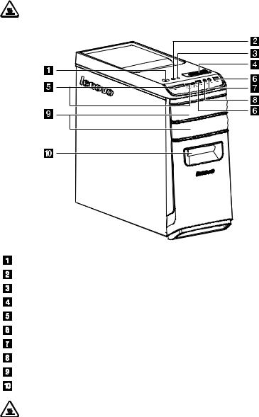
1.1 Front view of the chassis
Attention: Be careful not to block any air vents on the computer. Blocked air vents can cause overheating.
Power button
Power Control Switch indicator ON/OFF (selected models only) Hard disk drive indicator
Power control switch (selected models only) Memory card readers (selected models only) USB connector
Microphone connector Headphone connector
Optical drive (some models are equipped with only one optical drive) Hot plug HDD port (selected models only)
Attention: Do not insert 3-inch discs into the optical drive.
2 User Guide
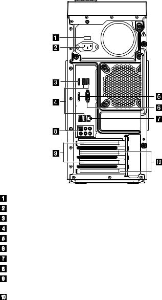
1.2 Rear view of the chassis
IdeaCentre K430
Voltage selection switch (selected models only) Power connector
HDMI connector (selected models only) USB connectors
DisplayPort connector (selected models only) On-board VGA connector
Ethernet connector Audio connectors
PCI Express X 16 graphics adapter connector (some models are equipped with a graphics card)
PCI Express X 1 adapter connector (some models are equipped with a WIFI card or TV tuner card)
User Guide 3
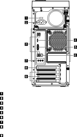
IdeaCentre K410
Voltage selection switch (selected models only) Power connector
USB connectors
HDMI connector (selected models only) On-board VGA connector
Ethernet connector Audio connectors
PCI Express X 16 graphics adapter connector (some models are equipped with a graphics card)
PCI Express X 1 adapter connector (some models are equipped with a WIFI card or TV tuner card)
4 User Guide
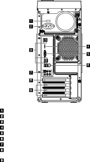
IdeaCentre K415
Voltage selection switch (selected models only) Power connector
USB connectors (USB ports 4 to 6) HDMI connector (selected models only) On-board VGA connector
Ethernet connector Audio connectors
PCI Express X 16 graphics adapter connector (some models are equipped with a graphics card)
PCI Express X 1 adapter connector (some models are equipped with a WIFI card or TV tuner card)
User Guide 5
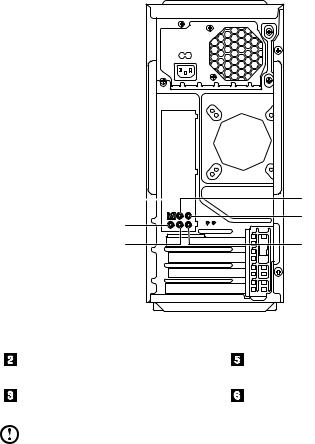
1.3 Connecting your computer
Note: Your computer may not have all of the connectors described in this section.
1.3.1Check the position of the voltage-selection switch on the rear of the computer. Use a ballpoint pen to slide the switch if necessary.
Note: Some computers do not have a voltage switch. These computers control voltage automatically.
•If the voltage supply range is 100-127 V AC, set the switch to 115 V.
•If the voltage supply range is 200-240 V AC, set the switch to 230 V.
115 |
230 |
1.3.2 Basic connector instructions
Connector |
Description |
|
|
Microphone |
Use this connector to attach a microphone to your |
|
computer when you want to record sound or if you |
|
use speech-recognition software. |
|
|
Headphone |
Use this connector to attach headphones to your |
|
computer when you want to listen to music or |
|
other sounds without disturbing anyone. |
|
|
Audio line-in connector |
Used to receive audio signals from an external |
|
audio device, such as a stereo system. When |
|
you attach an external audio device, a cable is |
|
connected between the audio line-out connector |
|
of the device and the audio line-in connector of |
|
the computer. |
|
|
6 User Guide

Audio line-out connector |
Used to send audio signals from the computer |
|
to external devices, such as powered stereo |
|
speakers (speakers with built-in amplifiers), |
|
headphones, multimedia keyboards, or the audio |
|
line-in connector on a stereo system or other |
|
external recording device. |
|
|
USB connector |
Use this connector to attach a device that requires |
|
a USB connection. |
|
|
Ethernet connector |
Use this connector to attach the computer to an |
|
Ethernet-type local area network. |
|
|
VGA connector |
Used to attach a VGA monitor or other devices |
|
that use a VGA monitor connector. |
|
|
DVI connector |
Used to attach a DVI monitor or other devices that |
|
use a DVI monitor connector. |
|
|
HDMI connector (optional) |
Connects to the HDMI connector on your display |
|
or TV. |
|
|
DisplayPort connector |
Used to attach a high-performance monitor, a |
(optional) |
direct-drive monitor, or other devices that use a |
|
DisplayPort connector. |
|
|
TV-Tuner connector (optional) |
Only supported on systems with optional TV tuner |
|
card. |
|
|
Note: If your computer is equipped with a wireless keyboard or mouse, follow the installation instructions for those devices.
User Guide 7
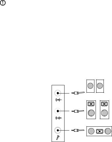
1.4 7.1 Audio configuration instructions
Use the following illustration when connecting a 7.1 surround sound audio system:
|
|
|
|
|
|
|
|
|
|
|
|
|
|
|
|
|
|
|
|
|
|
|
|
|
|
|
|
|
|
|
|
|
|
|
|
|
|
|
|
|
|
|
|
|
|
|
|
|
|
|
|
|
|
|
|
|
|
|
|
|
|
|
|
|
|
|
|
|
|
|
|
|
|
|
|
|
|
|
|
|
|
|
|
|
|
|
|
|
|
|
|
|
|
|
|
|
|
|
|
|
|
|
|
|
|
|
|
|
S/PDIF out connector |
|
|
Microphone input Connector |
|||||||
|
|
||||||||||
|
Center / Low frequency output |
|
|
Audio line-out Connector |
|||||||
|
connector |
|
|
|
|
|
|
||||
|
Surround out connector |
|
|
Audio line-in Connector |
|||||||
Note: For more detailed settings, click Start → Control panel → Hardware and Sound → Lenovo HD Audio Manager. Follow the instructions to configure advanced settings.
Sound configuration is as follows:
1.Right click the Sound icon in the system property bar and select the sounds option to setup the sounds in the pop-up dialog box.
2.Select a playback device from the playback dialog box, then click the configure button to configure it.
3.Select 7.1 surround from audio channels in the pop-up speaker setup dialog box and proceed with the speaker setup by following the prompts.
8 User Guide
4. 7.1 surround sound can be used once this configuration procedure is complete.
Note: If the audio configuration interfaces above are different from those on your computer, you may use the above steps as a reference to
configure the 7.1 surround sound audio device system in your actual audio configuration interface and read the electronic Help information for further assistance.
1.55.1 Audio configuration instructions
(This instruction is only for the pc model which mainboard supports audio transforming from 2.0 stereo to 5.1 surround.)
This model of computer supports transforming stereo sound into 5.1 surround sound.
Use the following guides when connecting to the 5.1 surround audio device:
Blue line-in connector
Surround
Green line-out connector
Front channel
Pink Mic-in connector
Center-LEF
The configurations are as followings:
1.Right click the Sound icon in system property bar and select sounds option to setup the sounds in the pop-up dialog box.
2.Select a playback device from the playback dialog box, and then click configure button to configure it.
3.Select 5.1 surround from audio channels in the pop-up speaker setup dialog box to proceed with the speaker setup by following as prompted.
4.After the configuration, 5.1 surround can be used.
User Guide 9

Note: If the audio configuration interfaces in above are different from your actual computer, you may use above steps as reference to configure the 5.1 surround audio device in your actual audio configuration interface and read the electronic Help information for further assistance.
1.6Connect the power cords properly to grounded electrical outlets
1.7 How to play Blu-ray Discs (selected models only)
Check the connectors available on your computer and display and select an appropriate cable according to this table. Because other types of cables do not meet the requirements of the Blu-ray standard.
You need to purchase the cable separately if the computer is not equipped with the corresponding cable.
This table will help you to identify the connectors on your computer and display.
Connection Type Computer |
Cable |
Display |
DVI to DVI |
|
|
(DVI cable) |
|
|
DVI to HDMI |
|
|
(DVI-HDMI |
|
|
cable) |
|
|
|
|
|
HDMI to HDMI |
|
|
(HDMI cable) |
|
|
HDMI to DVI |
|
||
(HDMI-DVI |
|
||
cable) |
|||
|
|||
10 |
User Guide |
|
|
1.8 Wired keyboard (selected models only)
LVT —— After entering Windows, press this key to launch the LVT (Lenovo Vantage Technology) program, Lenovo’s pre-loaded Home PC software. In addition to its own functions, the LVT program will allow you to start other Windows compatible software, specially configured to run on this model of computer.
F2 —— Your computer has the Lenovo Rescue System installed. To learn more about this program, repeatedly press and release the F2 key once turning on the computer until the Lenovo Rescue System open.
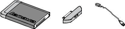
1.9 Hot-swappable hard disk (selected models only)
•Unpack
Hot-swappable hard disk |
USB adapter |
USB cable |
You may plug the hot-swappable hard disk conveniently while the computer system using it remains in operation, but will not damage the hard disk data. You may back up the data on this hot-swappable hard disk at any time for data maintenance or data transmission.
User Guide 11
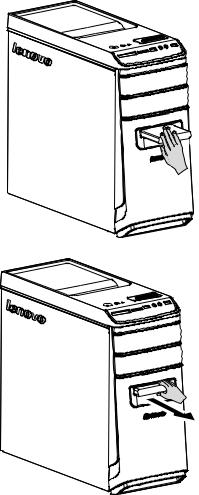
•Operation of the hot-swappable hard disk
Slide it into the bay from the front until it snaps into position.
Pull the hot-swappable hard disk drive out of the drive bay.
12 User Guide
•Connect the hot-swappable hard disk to the other computer
Notes:
•Don’t unplug the hard disk while it is copying the data to avoid result in a loss of data.
•After installing the hard disk and connecting all the cables, wait for a moment to make the system distinguish from the hard disk.
•Don’t install the operating system on the hot-swappable hard disk.
•Don’t unplug the hard disk while it is operating a software program to avoid collapse of system.
•After pulling out the hard disk, don’t beat the hard disk or throw it everywhere to damage it.
•Under the Rescue System, each function mode cannot distinguish from the hot-swappable hard disk.
User Guide 13
Loading...