

Page 1

ThinkCentre
HardwareMaintenanceManual
MachineTypes:0804,0806,0809,0810,0811,0821,0822,
0823,0825,0827,0828,0829,0830,0832,0833,0835,0837,0842,
0843,0844,0845,0846,0847,0848,0849,0851,and4089
Page 2

Page 3

ThinkCentre
HardwareMaintenanceManual
MachineTypes:0804,0806,0809,0810,0811,0821,0822,
0823,0825,0827,0828,0829,0830,0832,0833,0835,0837,0842,
0843,0844,0845,0846,0847,0848,0849,0851,and4089
Page 4

Note:Beforeusingthisinformationandtheproductitsupports,besuretoreadandunderstandChapter2
“Safetyinformation”onpage3andAppendixA“Notices”onpage395.
FifthEdition(May2011)
©CopyrightLenovo2010,2011.
LIMITEDANDRESTRICTEDRIGHTSNOTICE:IfdataorsoftwarearedeliveredpursuantaGeneralServices
Administration“GSA”contract,use,reproduction,ordisclosureissubjecttorestrictionssetforthinContractNo.
GS-35F-05925.
Page 5

Contents
Chapter1.Aboutthismanual.....1
Importantsafetyinformation..........1
ImportantinformationaboutreplacingRoHS
compliantFRUs...............1
Chapter2.Safetyinformation.....3
Generalsafety................3
Electricalsafety...............3
Voltage-selectionswitch............5
Safetyinspectionguide............5
Handlingelectrostaticdischarge-sensitive
devices..................6
Groundingrequirements............6
Safetynotices(multi-lingualtranslations).....6
Chapter3.Generalinformation....29
LenovoThinkVantageToolbox........29
ThinkVantageProductivityCenter.......29
LenovoWelcome..............29
Additionalinformationresources.......29
Specications...............30
Formachinetypes:0806,0810,0821,0823,
0827,0829,0832,0835,0842,0844,0846,
0848,0851,and4089...........30
Formachinetypes:0804,0809,0811,0822,
0825,0828,0830,0833,0837,0843,0845,
0847,and0849.............31
Chapter4.Generalcheckout.....33
Problemdeterminationtips..........33
Chapter5.Diagnosticprograms...35
LenovoThinkVantageToolbox........35
PC-DoctorforRescueandRecovery......35
PC-DoctorforDOS.............36
Creatingadiagnosticdisc........36
Runningthediagnosticprogramfromthe
diagnosticdisc.............36
Navigatingthroughthediagnosticprograms.36
Runningtests.............36
Viewingthetestlog...........38
Chapter6.UsingtheSetupUtility
program................39
StartingtheSetupUtilityprogram.......39
Viewingorchangingsettings.........39
Usingpasswords..............39
Passwordconsiderations.........40
Power-onpassword...........40
Administratorpassword.........40
Setting,changing,ordeletingapassword..40
Enablingordisablingadevice........40
Selectingastartupdevice..........41
Selectingatemporarystartupdevice....41
Viewingorchangingthestartupdevice
sequence...............41
ExitingtheSetupUtilityprogram.......42
Chapter7.Symptom-to-FRUindex.43
Harddiskdrivebooterror..........43
PowerSupplyProblems...........43
Diagnosticerrorcodes...........43
Beepsymptoms..............61
POSTerrorcodes.............62
Miscellaneouserrormessages........63
Undeterminedproblems...........65
Chapter8.ReplacingFRUs(Machine
Types:0806,0810,0821,0823,0827,
0829,0832,0835,0842,0844,0846,
0848,0851,and4089.).........67
Locatingconnectors,controls,andindicatorson
thefrontofyourcomputer..........67
Locatingconnectorsandpartsontherearofyour
computer.................68
Locatingcomponents............68
Locatingpartsonthesystemboard......69
Locatinginternaldrives...........70
Removingthecomputercover........71
Removingandreinstallingthefrontbezel....72
InstallingorreplacingaPCIcard.......74
Installingorreplacingamemorymodule....76
Replacingthebattery............78
Replacingthepowersupplyassembly.....79
Replacingtheheatsinkandfanassembly....81
Replacingthemicroprocessor........83
Replacingthesystemboard.........85
Replacingtheopticaldrive..........87
Replacingtheharddiskdrive.........89
ReplacingthefrontaudioandUSBassembly..91
Replacingtherearfanassembly........92
Completingthepartsreplacement.......94
Chapter9.ReplacingFRUs(Machine
Types:0804,0809,0811,0822,0825,
0828,0830,0833,0837,0843,0845,
0847,and0849.)............97
©CopyrightLenovo2010,2011
iii
Page 6

Locatingconnectors,controls,andindicatorson
thefrontofyourcomputer..........97
Locatingconnectorsandpartsontherearofyour
computer.................98
Locatingcomponents............98
Locatingpartsonthesystemboard......99
Locatinginternaldrives...........100
Removingthecomputercover........101
Removingandreinstallingthefrontbezel....102
Accessingthesystemboardcomponentsand
drives..................103
InstallingorreplacingaPCIcard.......105
Installingorreplacingamemorymodule....107
Replacingthebattery............108
Replacingtheheatsinkandfanassembly....110
Replacingthemicroprocessor........112
Replacingthesystemboard.........115
Replacingthepowersupplyassembly.....117
Replacingtheopticaldrive..........121
Replacingtheharddiskdrive.........124
Replacingthefrontfanassembly.......127
Completingthepartsreplacement.......129
Chapter10.FRUlists........131
Overall:MachineTypes:0806,0810,0821,0823,
0827,0829,0832,0835,0842,0844,0846,0848,
0851,and4089...............131
MechanicalFRUs.............151
KeyboardandMouse............157
AdaptersandmiscellaneousFRUs.......201
PowerCords...............204
Recoverydiscs..............215
Windows7HomeBasic32RecoveryCD..215
Windows7HomeBasic32OfceStarter
RecoveryCD.............218
Windows7HomePremium32Recovery
CD.................220
Windows7HomePremium32OfceStarter
RecoveryCD.............224
Windows7Professional32RecoveryCD..227
Windows7Professional32OfceStarter
RecoveryCD.............234
Windows7Professional64RecoveryCD..241
Windows7Professional64OfceStarter
RecoveryCD.............244
Windows7Starter32RecoveryCD....247
Windows7Starter32withofcestarter2010
RecoveryCD.............250
WindowsXPProfessional32RecoveryCD..252
WindowsVistaBusiness32SP2Recovery
CD.................258
WindowsVistaBusiness32SP2withofce
starter2010RecoveryCD........259
WindowsVistaHomeBasic32SP2Recovery
CD.................261
WindowsVistaHomeBasic32SP2withofce
starter2010RecoveryCD........262
WindowsVistaStarterSP2Ofce2010
RecoveryCD.............262
Overall:MachineTypes:0804,0809,0811,0822,
0825,0828,0830,0833,0837,0843,0845,0847,
and0849.................263
MechanicalFRUs.............279
KeyboardandMouse............287
AdaptersandmiscellaneousFRUs.......330
PowerCords...............334
Recoverydiscs..............343
Windows7HomeBasic32RecoveryCD..343
Windows7HomeBasic32ofcestarter2010
RecoveryCD.............345
Windows7HomePremium32Recovery
CD.................348
Windows7HomePremium32withofce
starter2010RecoveryCD........351
Windows7Professional32RecoveryCD..354
Windows7Professional32withofcestarter
2010RecoveryCD...........361
Windows7Professional64RecoveryCD..368
Windows7Professional64withofcestarter
2010RecoveryCD...........371
Windows7Starter32RecoveryCD....374
Windows7Starter32withofcestarter2010
RecoveryCD.............376
WindowsXPProfessional32RecoveryCD..378
WindowsVistaBusiness32SP2Recovery
CD.................385
WindowsVistaBusiness32SP2withofce
starter2010RecoveryCD........386
WindowsVistaHomeBasic32SP2Recovery
CD.................388
WindowsVistaHomeBasic32SP2withofce
starter2010RecoveryCD........389
WindowsVistaStarterSP2Ofce2010
RecoveryCD.............389
Chapter11.Additionalservice
information.............391
Securityfeatures..............391
Hardware-controlledpasswords......391
Operatingsystempassword.......391
VitalProductData...........391
BIOSlevels................391
Updating(ashing)theBIOSfromadisc....391
Updating(ashing)theBIOSfromyouroperating
system..................392
RecoveringfromaPOSTandBIOSupdate
failure..................392
ivThinkCentreHardwareMaintenanceManual
Page 7

Powermanagement............393
AdvancedCongurationandPowerInterface
(ACPI)BIOS..............393
AutomaticPower-Onfeatures.......393
AppendixA.Notices........395
Televisionoutputnotice...........396
EuropeanconformanceCEmark.......396
Trademarks................396
Index.................397
©CopyrightLenovo2010,2011
v
Page 8

viThinkCentreHardwareMaintenanceManual
Page 9
Chapter1.Aboutthismanual
ThismanualcontainsserviceandreferenceinformationforThinkCentre®computermachinetypeslistedon
thefrontcover.ThismanualisintendedonlyfortrainedServiceProviderswhoarefamiliarwithLenovo®
computerproducts.
Note:BesuretoreadandunderstandtheChapter2“Safetyinformation”onpage3beforeusingthe
informationinthismanual.
The“Symptom-to-FRUIndex”chapterandthe“Additionalserviceinformation”chapterapplytoall
ThinkCentrecomputers.
ThismanualincludesacompleteFRUpartnumberlistforeachmachinetypelistedonthefrontcover.Ifyou
haveinternetaccess,theFRUpartnumbersarealsoavailableat:
http://www.lenovo.com/support
Importantsafetyinformation
Besuretoreadallcautionanddangerstatementsinthismanualbeforeperforminganyoftheinstructions.
VeuillezliretouteslesconsignesdetypeDANGERetATTENTIONduprésentdocumentavantd'exécuter
lesinstructions.
LesenSieunbedingtalleHinweisevomTyp"ACHTUNG"oder"VORSICHT"indieserDokumentation,bevor
SieirgendwelcheVorgängedurchführen
LeggereleistruzioniintrodottedaATTENZIONEePERICOLOpresentinelmanualeprimadieseguireuna
qualsiasidelleistruzioni
Certique-sedelertodasasinstruçõesdecuidadoeperigonestemanualantesdeexecutarqualquer
umadasinstruções
Esimportantequeleatodaslasdeclaracionesdeprecauciónydepeligrodeestemanualantesdeseguir
lasinstrucciones.
ImportantinformationaboutreplacingRoHScompliantFRUs
RoHS,theRestrictionofHazardousSubstancesinElectricalandElectronicEquipmentDirective
(2002/95/EC)isaEuropeanUnionlegalrequirementaffectingtheglobalelectronicsindustry.RoHS
requirementsmustbeimplementedonLenovoproductsplacedonthemarketandsoldinthe
EuropeanUnionafterJune,2006.ProductsonthemarketbeforeJune,2006arenotrequiredto
haveRoHScompliantparts.Ifthepartsarenotcompliantoriginally,replacementpartscanalso
©CopyrightLenovo2010,2011
1
Page 10
benoncompliant,butinallcases,ifthepartsarecompliant,thereplacementpartsmustalsobe
compliant.
Note:RoHSandnon-RoHSFRUpartnumberswiththesametandfunctionareidentiedwithunique
FRUpartnumbers.
LenovoplanstotransitiontoRoHScompliancewellbeforetheimplementationdateandexpectsitssuppliers
tobereadytosupportLenovo'srequirementsandscheduleintheEU.Productssoldin2005willcontain
someRoHScompliantFRUs.ThefollowingstatementpertainstotheseproductsandanyproductLenovo
producescontainingRoHScompliantparts.
RoHScompliantThinkCentrepartshaveuniqueFRUpartnumbers.BeforeorafterJune2006,failedRoHS
compliantpartsmustalwaysbereplacedusingRoHScompliantFRUs,soonlytheFRUsidentiedas
compliantinthesystemhardwaremaintenancemanualordirectsubstitutionsforthoseFRUscanbeused.
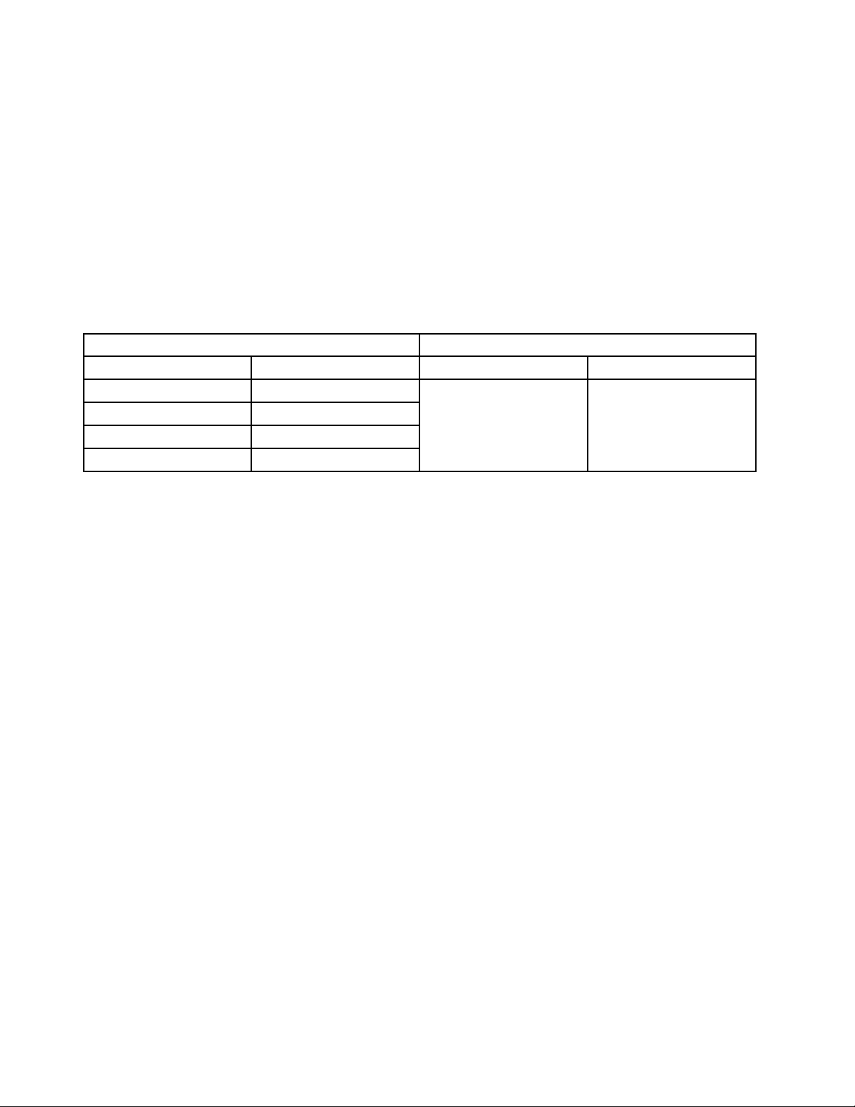
ProductsmarketedbeforeJune2006ProductsmarketedafterJune2006
Currentororiginalpart
Non-RoHSCanbeNon-RoHS
Non-RoHSCanbeRoHS
Non-RoHSCansubstitutetoRoHS
RoHSMustbeRoHS
ReplacementFRU
Currentororiginalpart
MustbeRoHSMustbeRoHS
ReplacementFRU
Note:AdirectsubstitutionisapartwithadifferentFRUpartnumberthatisautomaticallyshippedbythe
distributioncenteratthetimeoforder.
2ThinkCentreHardwareMaintenanceManual
Page 11

Chapter2.Safetyinformation
Thischaptercontainsthesafetyinformationthatyouneedtobefamiliarwithbeforeservicingacomputer.
Generalsafety
Followtheserulestoensuregeneralsafety:
•Observegoodhousekeepingintheareaofthemachinesduringandaftermaintenance.
•Whenliftinganyheavyobject:
1.Ensureyoucanstandsafelywithoutslipping.
2.Distributetheweightoftheobjectequallybetweenyourfeet.
3.Useaslowliftingforce.Nevermovesuddenlyortwistwhenyouattempttolift.
4.Liftbystandingorbypushingupwithyourlegmuscles;thisactionremovesthestrainfromthe
musclesinyourback.Donotattempttoliftanyobjectsthatweighmorethan16kg(35lb)orobjects
thatyouthinkaretooheavyforyou.
•Donotperformanyactionthatcauseshazardstothecustomer,orthatmakestheequipmentunsafe.
•Beforeyoustartthemachine,ensurethatotherservicerepresentativesandthecustomer'spersonnelare
notinahazardousposition.
•Placeremovedcoversandotherpartsinasafeplace,awayfromallpersonnel,whileyouareservicing
themachine.
•Keepyourtoolcaseawayfromwalkareassothatotherpeoplewillnottripoverit.
•Donotwearlooseclothingthatcanbetrappedinthemovingpartsofamachine.Ensurethatyoursleeves
arefastenedorrolledupaboveyourelbows.Ifyourhairislong,fastenit.
•Inserttheendsofyournecktieorscarfinsideclothingorfastenitwithanonconductiveclip,approximately
8centimeters(3inches)fromtheend.
•Donotwearjewelry,chains,metal-frameeyeglasses,ormetalfastenersforyourclothing.
Remember:Metalobjectsaregoodelectricalconductors.
•Wearsafetyglasseswhenyouare:hammering,drilling,soldering,cuttingwire,attachingsprings,using
solvents,orworkinginanyotherconditionsthatmightbehazardoustoyoureyes.
•Afterservice,reinstallallsafetyshields,guards,labels,andgroundwires.Replaceanysafetydevice
thatiswornordefective.
•Reinstallallcoverscorrectlybeforereturningthemachinetothecustomer.
Electricalsafety
CAUTION:
Electricalcurrentfrompower,telephone,andcommunicationcablescanbehazardous.Toavoid
personalinjuryorequipmentdamage,disconnecttheattachedpowercords,telecommunication
systems,networks,andmodemsbeforeyouopenthecentrecovers,unlessinstructedotherwisein
theinstallationandcongurationprocedures.
Observethefollowingruleswhenworkingonelectricalequipment.
©CopyrightLenovo2010,2011
3
Page 12

Important:Useonlyapprovedtoolsandtestequipment.Somehandtoolshavehandlescoveredwithasoft
materialthatdoesnotinsulateyouwhenworkingwithliveelectricalcurrents.Manycustomershave,near
theirequipment,rubberoormatsthatcontainsmallconductiveberstodecreaseelectrostaticdischarges.
Donotusethistypeofmattoprotectyourselffromanelectricshock.
•Findtheroomemergencypower-off(EPO)switch,disconnectingswitch,orelectricaloutlet.Ifanelectrical
accidentoccurs,youcanthenoperatetheswitchorunplugthepowercordquickly.
•Donotworkaloneunderhazardousconditionsornearequipmentthathashazardousvoltages.
•Disconnectallpowerbefore:
–Performingamechanicalinspection
–Workingnearpowersupplies
–RemovingorinstallingFieldReplaceableUnits(FRU)
•Beforeyoustarttoworkonthemachine,unplugthepowercord.Ifyoucannotunplugit,askthecustomer
topower-offthewallboxthatsuppliespowertothemachineandtolockthewallboxintheoffposition.
•Ifyouneedtoworkonamachinethathasexposedelectricalcircuits,observethefollowingprecautions:
–Ensurethatanotherperson,familiarwiththepower-offcontrols,isnearyou.
Remember:Anotherpersonmustbetheretoswitchoffthepower,ifnecessary.
–Useonlyonehandwhenworkingwithpowered-onelectricalequipment;keeptheotherhandinyour
pocketorbehindyourback.
Remember:Theremustbeacompletecircuittocauseanelectricshock.Byobservingtheabove
rule,youmaypreventacurrentfrompassingthroughyourbody.
–Whenusingatester,setthecontrolscorrectlyandusetheapprovedprobeleadsandaccessoriesfor
thattester.
–Standonsuitablerubbermats(obtainedlocally,ifnecessary)toinsulateyoufromgroundssuchas
metaloorstripsandmachineframes.
Observethespecialsafetyprecautionswhenyouworkwithveryhighvoltages;theseinstructionsarein
thesafetysectionsofmaintenanceinformation.Useextremecarewhenmeasuringhighvoltages.
•Regularlyinspectandmaintainyourelectricalhandtoolsforsafeoperationalcondition.
•Donotusewornorbrokentoolsandtesters.
•Neverassumethatpowerhasbeendisconnectedfromacircuit.First,checkthatithasbeenpowered-off.
•Alwayslookcarefullyforpossiblehazardsinyourworkarea.Examplesofthesehazardsaremoistoors,
nongroundedpowerextensioncables,powersurges,andmissingsafetygrounds.
•Donottouchliveelectricalcircuitswiththereectivesurfaceofaplasticdentalmirror.Thesurfaceis
conductive;suchtouchingcancausepersonalinjuryandmachinedamage.
•Donotservicethefollowingpartswiththepoweronwhentheyareremovedfromtheirnormaloperating
placesinamachine:
–Powersupplyunits
–Pumps
–Blowersandfans
–Motorgenerators
andsimilarunits.(Thispracticeensurescorrectgroundingoftheunits.)
•Ifanelectricalaccidentoccurs:
–Usecaution;donotbecomeavictimyourself.
–Switchoffpower.
–Sendanotherpersontogetmedicalaid.
4ThinkCentreHardwareMaintenanceManual
Page 13

Voltage-selectionswitch
Somecomputersareequippedwithavoltage-selectionswitchlocatednearthepower-cordconnection
pointonthecomputer.Ifyourcomputerhasavoltage-selectionswitch,ensurethatyousettheswitchto
matchthevoltageavailableatyourelectricaloutlet.Settingthevoltage-selectionswitchincorrectlycan
causepermanentdamagetothecomputer.
Ifyourcomputerdoesnothaveavoltage-selectionswitch,yourcomputerisdesignedtooperateonlyatthe
voltageprovidedinthecountryorregionwherethecomputerwasoriginallypurchased.
Ifyourelocateyourcomputertoanothercountry,beawareofthefollowing:
•Ifyourcomputerdoesnothaveavoltage-selectionswitch,donotconnectthecomputertoanelectrical
outletuntilyouhaveveriedthatthevoltageprovidedisthesameasitwasinthecountryorregion
wherethecomputerwasoriginallypurchased.
•Ifyourcomputerhasavoltage-selectionswitch,donotconnectthecomputertoanelectricaloutletuntil
youhaveveriedthatthevoltage-selectionswitchissettomatchthevoltageprovidedinthatcountry
orregion.
Ifyouarenotsureofthevoltageprovidedatyourelectricaloutlet,contactyourlocalelectriccompanyor
refertoofcialWebsitesorotherliteraturefortravelerstothecountryorregionwhereyouarelocated.
Safetyinspectionguide
Theintentofthisinspectionguideistoassistyouinidentifyingpotentiallyunsafeconditionsonthese
products.Eachmachine,asitwasdesignedandbuilt,hadrequiredsafetyitemsinstalledtoprotectusers
andservicepersonnelfrominjury.Thisguideaddressesonlythoseitems.However,goodjudgmentshould
beusedtoidentifypotentialsafetyhazardsduetoattachmentoffeaturesoroptionsnotcoveredbythis
inspectionguide.
Ifanyunsafeconditionsarepresent,youmustdeterminehowserioustheapparenthazardcouldbeand
whetheryoucancontinuewithoutrstcorrectingtheproblem.
Considertheseconditionsandthesafetyhazardstheypresent:
•Electricalhazards,especiallyprimarypower(primaryvoltageontheframecancauseseriousorfatal
electricalshock).
•Explosivehazards,suchasadamagedCRTfaceorbulgingcapacitor
•Mechanicalhazards,suchaslooseormissinghardware
Theguideconsistsofaseriesofstepspresentedinachecklist.Beginthecheckswiththepoweroff,and
thepowercorddisconnected.
Checklist:
1.Checkexteriorcoversfordamage(loose,broken,orsharpedges).
2.Power-offthecomputer.Disconnectthepowercord.
3.Checkthepowercordfor:
a.Athird-wiregroundconnectoringoodcondition.Useametertomeasurethird-wireground
continuityfor0.1ohmorlessbetweentheexternalgroundpinandframeground.
b.Thepowercordshouldbetheappropriatetypeasspeciedinthepartslistings.
c.Insulationmustnotbefrayedorworn.
4.Removethecover.
Chapter2.Safetyinformation5
Page 14

5.Checkforanyobviousalterations.Usegoodjudgmentastothesafetyofanyalterations.
6.Checkinsidetheunitforanyobviousunsafeconditions,suchasmetallings,contamination,wateror
otherliquids,orsignsofreorsmokedamage.
7.Checkforworn,frayed,orpinchedcables.
8.Checkthatthepower-supplycoverfasteners(screwsorrivets)havenotbeenremovedortamperedwith.
Handlingelectrostaticdischarge-sensitivedevices
Anycomputerpartcontainingtransistorsorintegratedcircuits(ICs)shouldbeconsideredsensitiveto
electrostaticdischarge(ESD).ESDdamagecanoccurwhenthereisadifferenceinchargebetweenobjects.
ProtectagainstESDdamagebyequalizingthechargesothatthemachine,thepart,theworkmat,andthe
personhandlingthepartareallatthesamecharge.
Notes:
1.Useproduct-specicESDprocedureswhentheyexceedtherequirementsnotedhere.
2.MakesurethattheESDprotectivedevicesyouusehavebeencertied(ISO9000)asfullyeffective.
WhenhandlingESD-sensitiveparts:
•Keepthepartsinprotectivepackagesuntiltheyareinsertedintotheproduct.
•Avoidcontactwithotherpeoplewhilehandlingthepart.
•Wearagroundedwriststrapagainstyourskintoeliminatestaticonyourbody.
•Preventthepartfromtouchingyourclothing.Mostclothingisinsulativeandretainsachargeevenwhen
youarewearingawriststrap.
•Usetheblacksideofagroundedworkmattoprovideastatic-freeworksurface.Thematisespecially
usefulwhenhandlingESD-sensitivedevices.
•Selectagroundingsystem,suchasthoselistedbelow,toprovideprotectionthatmeetsthespecic
servicerequirement.
Note:TheuseofagroundingsystemisdesirablebutnotrequiredtoprotectagainstESDdamage.
–AttachtheESDgroundcliptoanyframeground,groundbraid,orgreen-wireground.
–UseanESDcommongroundorreferencepointwhenworkingonadouble-insulatedor
battery-operatedsystem.Youcanusecoaxorconnector-outsideshellsonthesesystems.
–Usetheroundground-prongoftheacplugonac-operatedcomputers.
Groundingrequirements
Electricalgroundingofthecomputerisrequiredforoperatorsafetyandcorrectsystemfunction.Proper
groundingoftheelectricaloutletcanbeveriedbyacertiedelectrician.
Safetynotices(multi-lingualtranslations)
Thecautionanddangersafetynoticesinthissectionareprovidedinthefollowinglanguages:
•English
•Arabic
•Brazilian/Portuguese
•Chinese(simplied)
•Chinese(traditional)
6ThinkCentreHardwareMaintenanceManual
Page 15
•French
•German
•Hebrew
•Italian
•Korean
•Spanish
DANGER
Electricalcurrentfrompower,telephoneandcommunicationcablesishazardous.
Toavoidashockhazard:
•Donotconnectordisconnectanycablesorperforminstallation,maintenance,orreconguration
ofthisproductduringanelectricalstorm.
•Connectallpowercordstoaproperlywiredandgroundedelectricaloutlet.
•Connecttoproperlywiredoutletsanyequipmentthatwillbeattachedtothisproduct.
•Whenpossible,useonehandonlytoconnectordisconnectsignalcables.
•Neverturnonanyequipmentwhenthereisevidenceofre,water,orstructuraldamage.
•Disconnecttheattachedpowercords,telecommunicationssystems,networks,andmodems
beforeyouopenthedevicecovers,unlessinstructedotherwiseintheinstallationandconguration
procedures.
•Connectanddisconnectcablesasdescribedinthefollowingtableswheninstalling,moving,or
openingcoversonthisproductorattacheddevices.
ToConnectToDisconnect
1.TurneverythingOFF .
2.First,attachallcablestodevices.
3.Attachsignalcablestoconnectors.
4.Attachpowercordstooutlet.
5.TurndeviceON.
1.TurneverythingOFF .
2.First,removepowercordsfromoutlet.
3.Removesignalcablesfromconnectors.
4.Removeallcablesfromdevices.
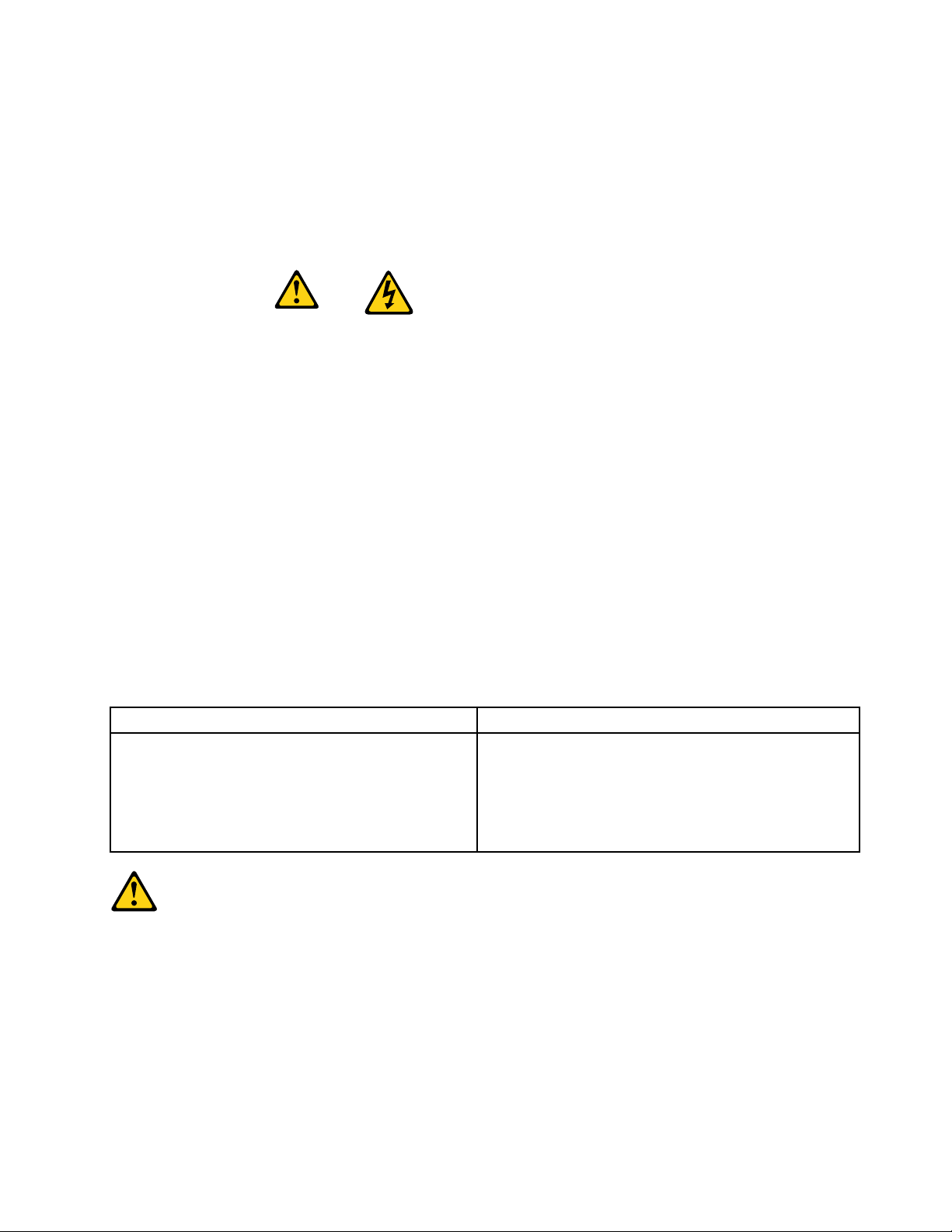
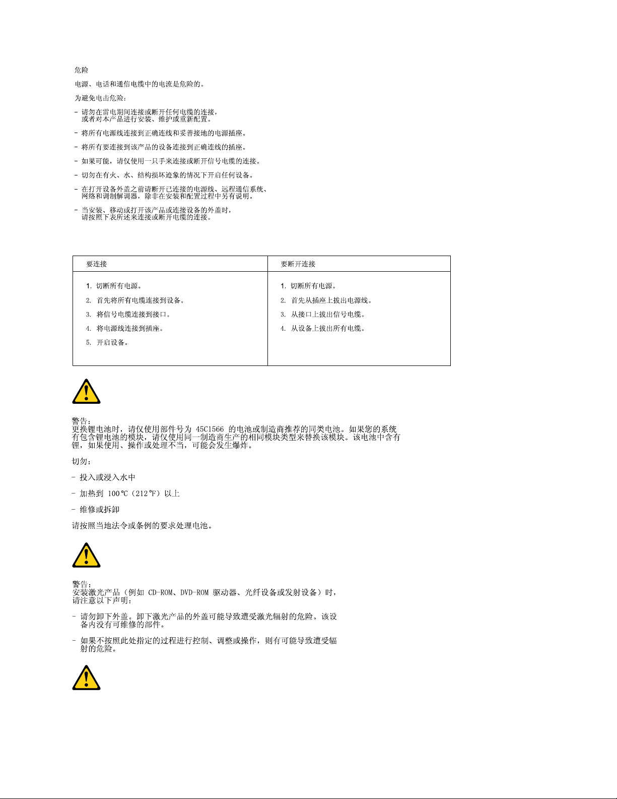
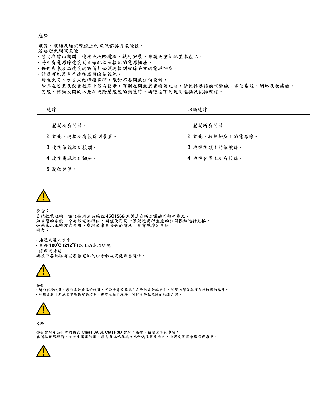
CAUTION:
Whenreplacingthelithiumbattery,useonlyPartNumber45C1566oranequivalenttypebattery
recommendedbythemanufacturer.Ifyoursystemhasamodulecontainingalithiumbattery,replace
itonlywiththesamemoduletypemadebythesamemanufacturer.Thebatterycontainslithiumand
canexplodeifnotproperlyused,handled,ordisposedof.Donot:
•Throworimmerseintowater
•Heattomorethan100°C(212°F)
•Repairordisassemble
Disposeofthebatteryasrequiredbylocalordinancesorregulations.
Chapter2.Safetyinformation7
Page 16
CAUTION:
1
2
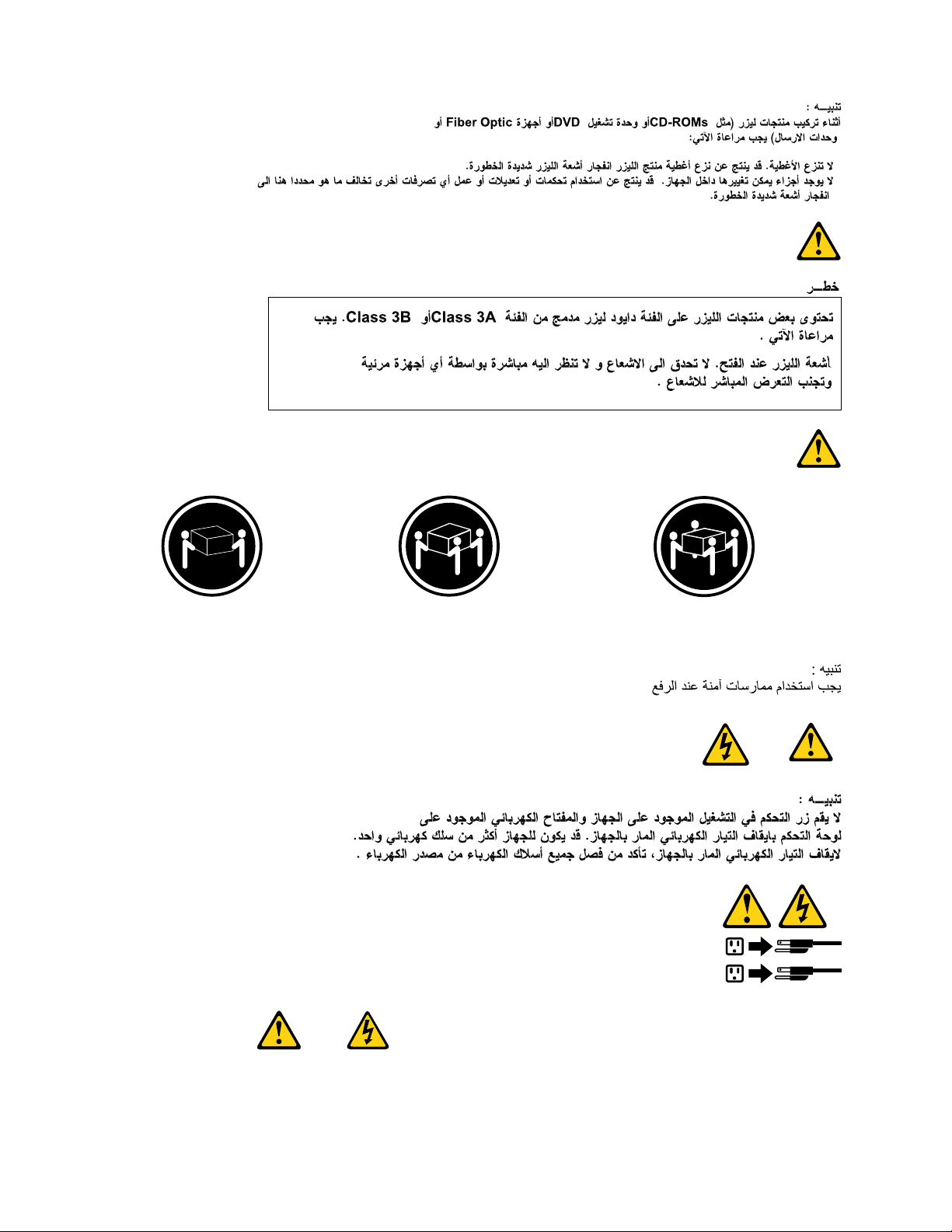
Whenlaserproducts(suchasCD-ROMs,DVD-ROMdrives,beropticdevices,ortransmitters)are
installed,notethefollowing:
•Donotremovethecovers.Removingthecoversofthelaserproductcouldresultinexposureto
hazardouslaserradiation.Therearenoserviceablepartsinsidethedevice.
•Useofcontrolsoradjustmentsorperformanceofproceduresotherthanthosespeciedherein
mightresultinhazardousradiationexposure.
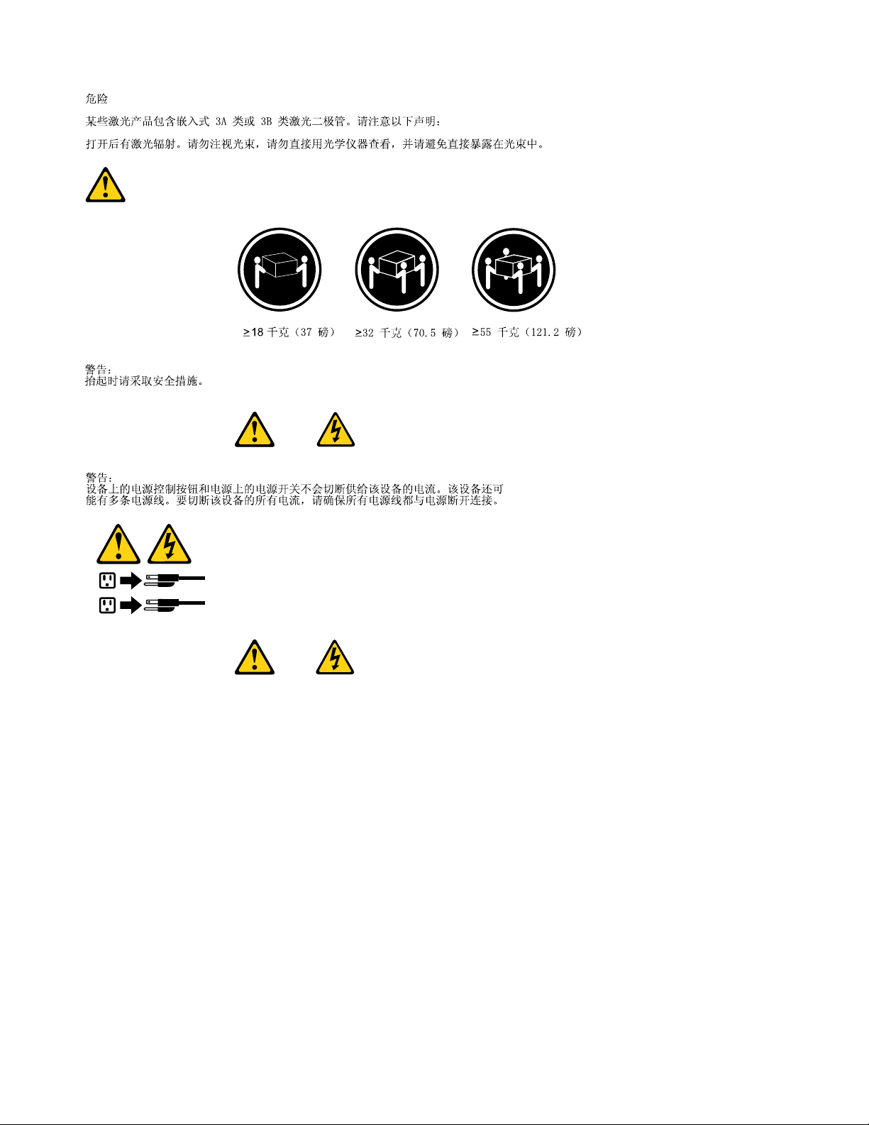
DANGER
SomelaserproductscontainanembeddedClass3AorClass3Blaserdiode.Notethefollowing:
Laserradiationwhenopen.Donotstareintothebeam,donotviewdirectlywithoptical
instruments,andavoiddirectexposuretothebeam.
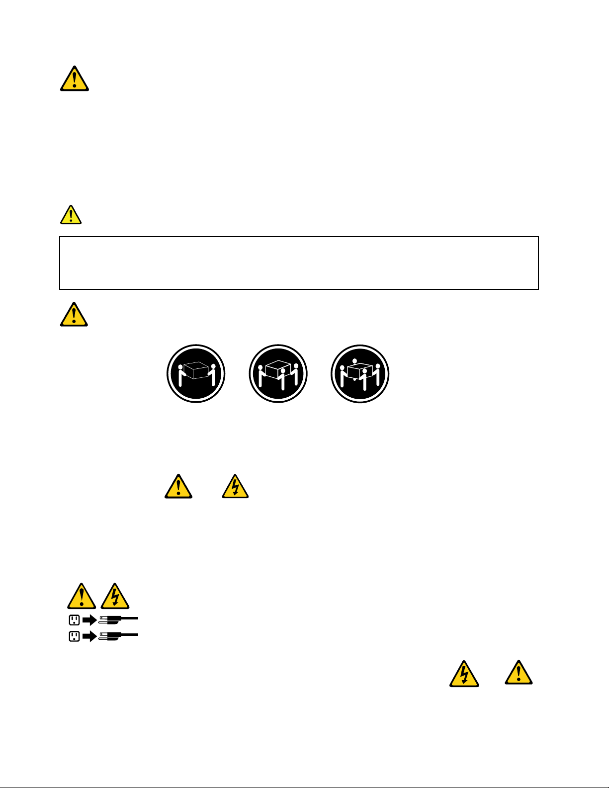
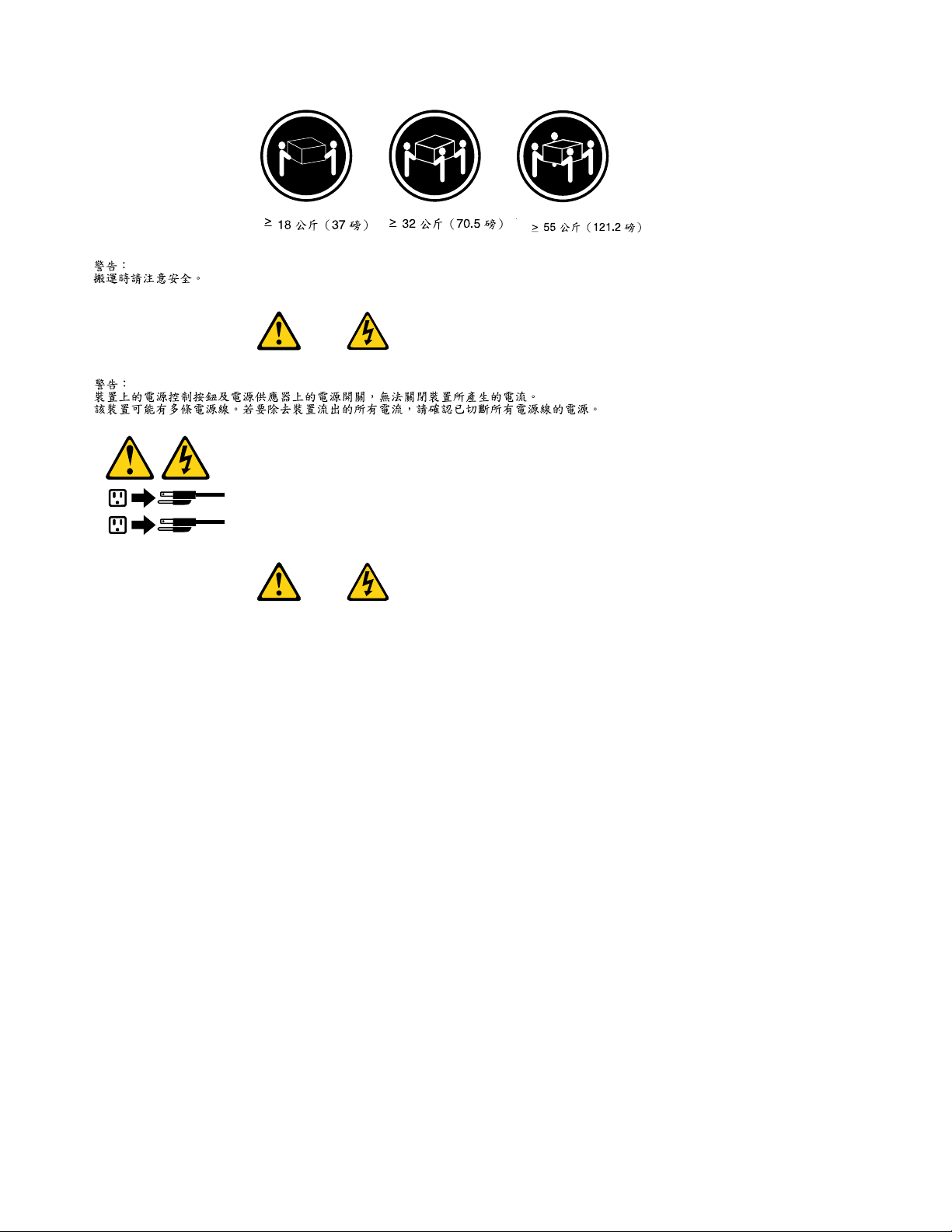
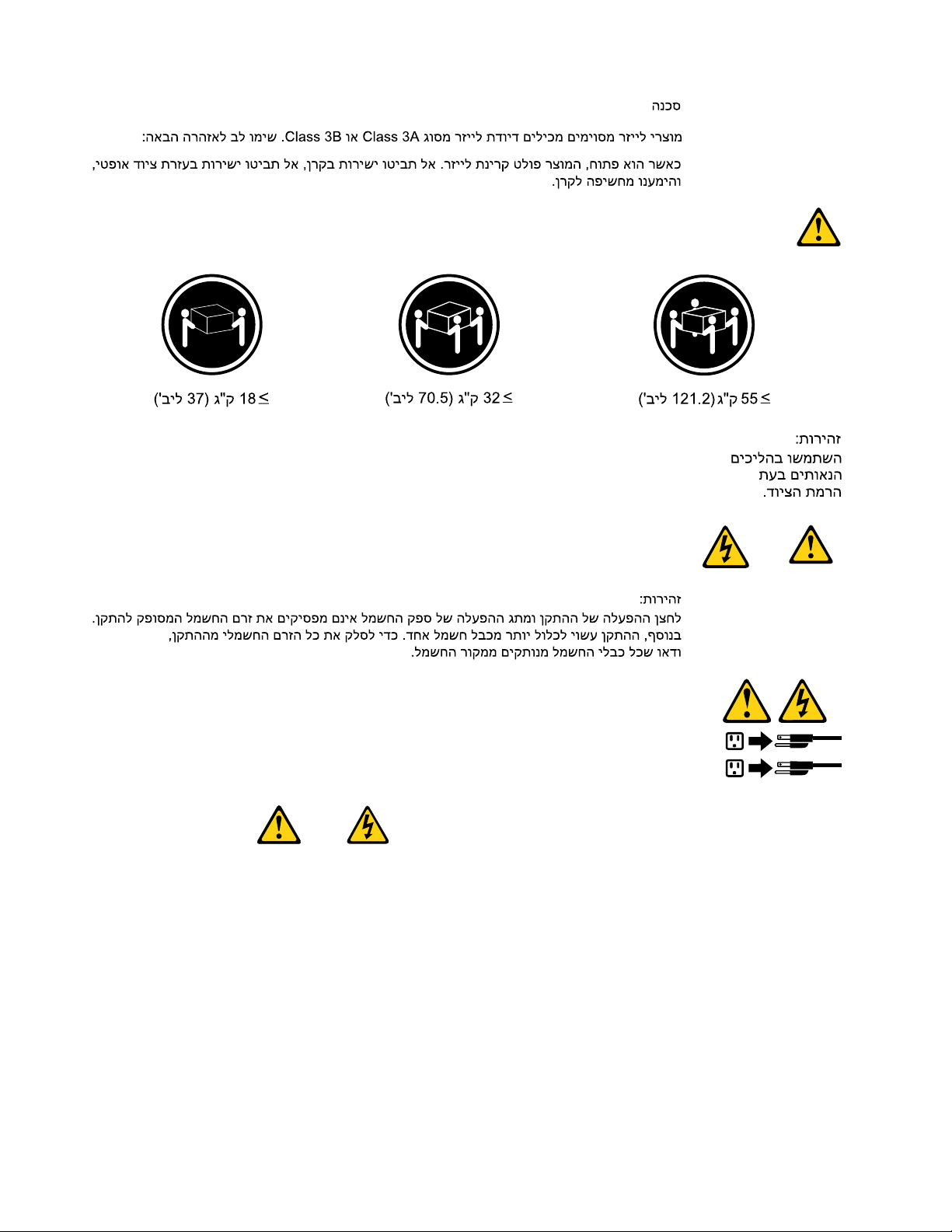
≥18kg(37lbs)≥32kg(70.5lbs)≥55kg(121.2lbs)
CAUTION:
Usesafepracticeswhenlifting.
CAUTION:
Thepowercontrolbuttononthedeviceandthepowerswitchonthepowersupplydonotturnoff
theelectricalcurrentsuppliedtothedevice.Thedevicealsomighthavemorethanonepower
cord.Toremoveallelectricalcurrentfromthedevice,ensurethatallpowercordsaredisconnected
fromthepowersource.
8ThinkCentreHardwareMaintenanceManual
Page 17
Chapter2.Safetyinformation9
Page 18
≥18kg(37lbs)≥32kg(70.5lbs)≥55kg(121.2lbs)
1
2
PERIGO
10ThinkCentreHardwareMaintenanceManual
Page 19
Acorrenteelétricaprovenientedecabosdealimentação,detelefoneedecomunicaçõeséperigosa.
Paraevitarriscodechoqueelétrico:
•Nãoconectenemdesconectenenhumcaboouexecuteinstalação,manutençãooureconguração
desteprodutoduranteumatempestadecomraios.
•Conectetodososcabosdealimentaçãoatomadaselétricascorretamenteinstaladaseaterradas.
•T odoequipamentoqueforconectadoaesteprodutodeveserconectadoatomadascorretamente
instaladas.
•Quandopossível,utilizeapenasumadasmãosparaconectaroudesconectarcabosdesinal.
•Nuncaliguenenhumequipamentoquandohouverevidênciadefogo,águaoudanosestruturais.
•Antesdeabrirtampasdedispositivos,desconectecabosdealimentação,sistemasdetelecomunicação,
redesemodemsconectados,amenosqueespecicadodemaneiradiferentenosprocedimentosde
instalaçãoeconguração.
•Conecteedesconecteoscabosconformedescritonatabelaapresentadaaseguiraoinstalar,moverou
abrirtampasdesteprodutooudedispositivosconectados.
ParaConectar:ParaDesconectar:
1.DESLIGUETudo.
2.Primeiramente,conectetodososcabosaos
dispositivos.
3.Conecteoscabosdesinalaosconectores.
4.Conecteoscabosdealimentaçãoàstomadas.
5.LIGUEosdispositivos.
1.DESLIGUETudo.
2.Primeiramente,removaoscabosdealimentaçãodas
tomadas.
3.Removaoscabosdesinaldosconectores.
4.Removatodososcabosdosdispositivos.
CUIDADO:
Aosubstituirabateriadelítio,utilizeapenasumabateriacomNúmerodePeça45C1566ouumtipo
debateriaequivalenterecomendadopeloSeoseusistemapossuiummódulocomumabateriade
lítio,substitua-oapenasporummódulodomesmotipoedomesmofabricante.Abateriacontémlítio
epodeexplodirsenãoforutilizada,manuseadaoudescartadademaneiracorreta.
Não:
•Jogueoucoloquenaágua
•Aqueçaamaisde100°C(212°F)
•Consertenemdesmonte
Descarteabateriaconformerequeridopelasleisouregulamentoslocais.
PRECAUCIÓN:
Quandoprodutosalaser(comounidadesdeCD-ROMs,unidadesdeDVD-ROM,dispositivosdebraótica
outransmissores)estivereminstalados,observeoseguinte:
Chapter2.Safetyinformation11
Page 20
•Nãoremovaastampas.Aremoçãodastampasdeumprodutoalaserpoderesultaremexposição
1
2
prejudicialàradiaçãodelaser.Nãoexistempeçasquepodemserconsertadasnointeriordodispositivo.
•Autilizaçãodecontrolesouajustesouaexecuçãodeprocedimentosdiferentesdosespecicadosaqui
poderesultaremexposiçãoprejudicialàradiação.
PERIGO
AlgunsprodutosalasercontêmdiododelaserintegradodaClasse3AoudaClasse3B.Observeoseguinte:
Radiaçãoalaserquandoaberto.Nãoolhediretamenteparaofeixeaolhonuoucominstrumentosópticose
eviteexposiçãodiretaaofeixe.
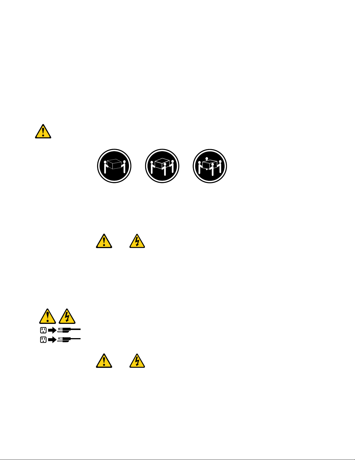
≥18kg(37lbs)≥32kg(70.5lbs)≥55kg(121.2lbs)
CUIDADO:
Utilizeprocedimentosdesegurançaparalevantarequipamentos.
CUIDADO:
Obotãodecontroledealimentaçãododispositivoeobotãoparaligar/desligardafontedealimentação
nãodesligamacorrenteelétricafornecidaaodispositivo.Odispositivotambémpodetermaisdeumcabo
dealimentação.Pararemovertodaacorrenteelétricadodispositivo,assegurequetodososcabosde
alimentaçãoestejamdesconectadosdafontedealimentação.
12ThinkCentreHardwareMaintenanceManual
Page 21
Chapter2.Safetyinformation13
Page 22
1
2
14ThinkCentreHardwareMaintenanceManual
Page 23
Chapter2.Safetyinformation15
Page 24
1
2
DANGER
Lecourantélectriqueprovenantdel'alimentation,dutéléphoneetdescâblesdetransmissionpeutprésenter
undanger.
Pourévitertoutrisquedechocélectrique:
•Nemanipulezaucuncâbleetn'effectuezaucuneopérationd'installation,d'entretienoudereconguration
deceproduitaucoursd'unorage.
•Brancheztouslescordonsd'alimentationsurunsocledeprisedecourantcorrectementcâbléetmisàla
terre.
•Branchezsurdessoclesdeprisedecourantcorrectementcâbléstoutéquipementconnectéàceproduit.
•Lorsquecelaestpossible,n'utilisezqu'uneseulemainpourconnecteroudéconnecterlescâbles
d'interface.
•Nemettezjamaisunéquipementsoustensionencasd'incendieoud'inondation,ouenprésencede
dommagesmatériels.
•Avantderetirerlescartersdel'unité,mettezcelle-cihorstensionetdéconnectezsescordons
d'alimentation,ainsiquelescâblesquilarelientauxréseaux,auxsystèmesdetélécommunicationetaux
modems(saufinstructioncontrairementionnéedanslesprocéduresd'installationetdeconguration).
•Lorsquevousinstallez,quevousdéplacez,ouquevousmanipulezleprésentproduitoudespériphériques
quiluisontraccordés,reportez-vousauxinstructionsci-dessouspourconnecteretdéconnecterles
différentscordons.
16ThinkCentreHardwareMaintenanceManual
Page 25
ConnexionDéconnexion
1.MettezlesunitésHORSTENSION.
2.Commencezparbranchertouslescordonssurles
unités.
3.Branchezlescâblesd'interfacesurdesconnecteurs.
4.Branchezlescordonsd'alimentationsurdesprises.
5.MettezlesunitésSOUSTENSION.
1.MettezlesunitésHORSTENSION.
2.Débranchezlescordonsd'alimentationdesprises.
3.Débranchezlescâblesd'interfacedesconnecteurs.
4.Débrancheztouslescâblesdesunités.
ATTENTION:
Remplacerlapileaulithiumusagéeparunepilederéférenceidentiqueexclusivement,(référence
45C1566),ousuivrelesinstructionsdufabricantquiendénitleséquivalences.Sivotresystèmeest
dotéd'unmodulecontenantunepileaulithium,vousdevezleremplaceruniquementparunmodule
identique,produitparlemêmefabricant.Lapilecontientdulithiumetpeutexploserencasde
mauvaiseutilisation,demauvaisemanipulationoudemiseaurebutinappropriée.
Nepas:
•lajeteràl'eau,
•l'exposeràdestempératuressupérieuresà100°C,
•chercheràlaréparerouàladémonter.
Nepasmettrelapileàlapoubelle.Pourlamiseaurebut,sereporteràlaréglementationenvigueur.
ATTENTION:
Sidesproduitsàlaser(telsquedesunitésdeCD-ROM,deDVD-ROM,desunitésàbresoptiques,ou
desémetteurs)sontinstallés,prenezconnaissancedesinformationssuivantes:
•Neretirezpaslecarter.Enouvrantl'unitédeCD-ROMoudeDVD-ROM,vousvousexposezau
rayonnementdangereuxdulaser.Aucunepiècedel'unitén'estréparable.
•Pourévitertoutrisqued'expositionaurayonlaser,respectezlesconsignesderéglageet
d'utilisationdescommandes,ainsiquelesprocéduresdécritesdansleprésentmanuel.
DANGER
Certainsproduitsàlasercontiennentunediodeàlaserintégréedeclasse3Aou3B.Prenez
connaissancedesinformationssuivantes:
Rayonnementlaserlorsquelecarterestouvert.Eviteztouteexpositiondirecteaurayonlaser.Evitez
deregarderxementlefaisceauoudel'observeràl'aided'instrumentsoptiques.
Chapter2.Safetyinformation17
Page 26
≥18kg(37lbs)≥32kg(70.5lbs)≥55kg(121.2lbs)
1
2
ATTENTION:
Soulevezlamachineavecprécaution.
ATTENTION:
L'interrupteurdecontrôled'alimentationdel'unitéetl'interrupteurdublocd'alimentationnecoupent
paslecourantélectriquealimentantl'unité.Enoutre,lesystèmepeutêtreéquipédeplusieurs
cordonsd'alimentation.Pourmettrel'unitéhorstension,vousdevezdéconnectertouslescordons
delasourced'alimentation.
VORSICHT
AnNetz-,Telefon-undDatenleitungenkönnengefährlicheSpannungenanliegen.
AusSicherheitsgründen:
•BeiGewitterandiesemGerätkeineKabelanschließenoderlösen.FernerkeineInstallations-,
Wartungs-oderRekongurationsarbeitendurchführen.
•GerätnuraneineSchutzkontaktsteckdosemitordnungsgemäßgeerdetemSchutzkontakt
anschließen.
•AlleangeschlossenenGeräteebenfallsanSchutzkontaktsteckdosenmitordnungsgemäß
geerdetemSchutzkontaktanschließen.
•DieSignalkabelnachMöglichkeiteinhändiganschließenoderlösen,umeinenStromschlagdurch
BerührenvonOberächenmitunterschiedlichemelektrischemPotenzialzuvermeiden.
•Geräteniemalseinschalten,wennHinweiseaufFeuer,WasseroderGebäudeschädenvorliegen.
18ThinkCentreHardwareMaintenanceManual
Page 27
•DieVerbindungzudenangeschlossenenNetzkabeln,Telekommunikationssystemen,Netzwerken
undModemsistvordemÖffnendesGehäuseszuunterbrechen,sofernindenInstallations-und
KongurationsprozedurenkeineanderslautendenAnweisungenenthaltensind.
•ZumInstallieren,TransportierenundÖffnenderAbdeckungendesComputersoderder
angeschlossenenEinheitendieKabelgemäßderfolgendenTabelleanschließenundabziehen.
ZumAnschließenderKabelgehenSiewiefolgtvorZumAbziehenderKabelgehenSiewiefolgtvor
1.SchaltenSiealleEinheitenAUS.
2.SchließenSieerstalleKabelandieEinheitenan.
3.SchließenSiedieSignalkabelandieBuchsenan.
4.SchließenSiedieNetzkabelandieSteckdosean.
5.SchaltenSiedieEinheitEIN.
1.SchaltenSiealleEinheitenAUS.
2.ZiehenSiezuerstalleNetzkabelausden
Netzsteckdosen.
3.ZiehenSiedieSignalkabelausdenBuchsen.
4.ZiehenSiealleKabelvondenEinheitenab.
CAUTION:
EineverbrauchteLithiumbatterienurdurcheineBatteriemitderTeilenummer45C1566odereine
gleichwertige,vomHerstellerempfohleneBatterieersetzen.EnthältdasSystemeinModulmiteiner
Lithiumbatterie,diesesnurdurcheinModuldesselbenTypsundvondemselbenHerstellerersetzen.
DieBatterieenthältLithiumundkannbeiunsachgemäßerVerwendung,HandhabungoderEntsorgung
explodieren.
DieBatterienicht:
•mitWasserinBerührungbringen.
•über100Cerhitzen.
•reparierenoderzerlegen.
DieörtlichenBestimmungenfürdieEntsorgungvonSondermüllbeachten.
ACHTUNG:
BeiderInstallationvonLasergeräten(wieCD-ROM-Laufwerken,DVD-aufwerken,Einheitenmit
LichtwellenleitertechnikoderSendern)Folgendesbeachten:
•DieAbdeckungennichtentfernen.DurchEntfernenderAbdeckungendesLasergerätskönnen
gefährlicheLaserstrahlungenfreigesetztwerden.DasGerätenthältkeinezuwartendenTeile.
•WerdenSteuerelemente,EinstellungenoderDurchführungenvonProzedurenandersalshier
angegebenverwendet,kanngefährlicheLaserstrahlungauftreten.
VORSICHT
EinigeLasergeräteenthalteneineLaserdiodederKlasse3Aoder3B.BeachtenSieFolgendes:
Chapter2.Safetyinformation19
Page 28
LaserstrahlungbeigeöffneterVerkleidung.NichtindenStrahlblicken.KeineLupenoderSpiegel
1
2
verwenden.Strahlungsbereichmeiden.
≥18kg(37lbs)≥32kg(70.5lbs)≥55kg(121.2lbs)
ACHTUNG:
ArbeitsschutzrichtlinienbeimAnhebenderMaschinebeachten.
ACHTUNG:
MitdemNetzschalteranderEinheitundamNetzteilwirddieStromversorgungfürdieEinheit
nichtunterbrochen.DieEinheitkannauchmitmehrerenNetzkabelnausgestattetsein.Umdie
StromversorgungfürdieEinheitvollständigzuunterbrechen,müssenallezumGerätführenden
NetzkabelvomNetzgetrenntwerden.
20ThinkCentreHardwareMaintenanceManual
Page 29
Chapter2.Safetyinformation21
Page 30
1
2
PERICOLO
Lacorrenteelettricaprovenientedaicavidialimentazione,deltelefonoedicomunicazionepuòessere
pericolosa.
Perevitareilrischiodiscosseelettriche:
•Noncollegareoscollegarequalsiasicavooppureeffettuarel'installazione,lamanutenzioneola
ricongurazionedelprodottoduranteuntemporale.
•Collegaretuttiilielettriciaunapresadialimentazionecorrettamentecablataedotatadimessaa
terra.
•Collegareallepreseelettricheappropriatetutteleapparecchiaturecheverrannoutilizzateper
questoprodotto.
22ThinkCentreHardwareMaintenanceManual
Page 31

•Sepossibile,utilizzaresolounamanopercollegareoscollegareicavidisegnale.
•Nonaccendereassolutamenteapparecchiatureinpresenzadiincendi,perdited'acquaodanno
strutturale.
•Scollegareicavidialimentazione,isistemiditelecomunicazione,leretieilmodemprimadi
aprireicoperchideldispositivo,salvoistruzionicontrarierelativealleprocedurediinstallazionee
congurazione.
•Collegareescollegareicavicomedescrittonellaseguentetabellaquandovengonoeffettuate
operazionidiinstallazione,spostamentooaperturadeicoperchidiquestoprodottoodelleunità
collegate.
PercollegarsiPerscollegarsi
1.SPEGNEREleapparecchiature.
2.Innanzitutto,collegaretuttiicavialleunità.
3.Collegareicavidisegnaleaiconnettori.
4.Collegareicavidialimentazioneallapresa.
5.Accenderel'unità.
1.SPEGNEREleapparecchiature.
2.Innanzitutto,rimuovereicavidialimentazionedalla
presa.
3.Rimuovereicavidisegnaledaiconnettori.
4.Rimuoveretuttiicavidalleunità.
ATTENZIONE:
Quandosisostituiscelabatteriaallitio,utilizzaresoloilNumeroparte45C1566ountipodibatteria
equivalenteconsigliatodalproduttore.Sesulsistemaèpresenteunmodulochecontieneunabatteria
allitio,sostituirlosoloconuntipodimodulodellostessotipodellastessacasadiproduzione.La
batteriacontienelitioepuòesplodereseusata,maneggiataosmaltitainmodononcorretto.
Non:
•Gettareoimmergerelabatterianell'acqua
•Riscaldarlaadunatemperaturasuperioreai100gradiC(212gradiF)
•Smontarla,ricaricarlaotentarediripararla
Lebatterieusatevannosmaltiteinaccordoallanormativainvigore(DPR915/82esuccessive
disposizioniedisposizionilocali).
ATTENZIONE:
Quandovengonoinstallatiprodottilaser(qualiCD-ROM,unitàDVD-ROM,unitàabreotticheo
trasmittenti),tenerpresentequantosegue:
•Nonrimuovereglisportelli.L'aperturadiun'unitàlaserpuòdeterminarel'esposizionearadiazioni
laserpericolose.All'internodell'unitànonvisonopartisucuieffettuarel'assistenzatecnica.
•L'utilizzodicontrolli,regolazioniol'esecuzionediprocedurenondescrittinelpresentemanuale
possonoprovocarel'esposizionearadiazionipericolose.
Chapter2.Safetyinformation23
Page 32

PERICOLO
1
2
AlcuneunitàlasercontengonoundiodolaserdiClasse3AoClasse3B.Tenerpresentequantosegue:
Aprendol'unitàvengonoemesseradiazionilaser.Nonssareilfascio,nonguardarlodirettamente
construmentiotticiedevitarel'esposizionealfascio.
≥18kg(37lbs)≥32kg(70.5lbs)≥55kg(121.2lbs)
ATTENZIONE:
Prestareattenzionenelsollevarel'apparecchiatura.
ATTENZIONE:
Ilpulsantedicontrollodell'alimentazionepresentesull'unitàel'interruttoredell'alimentatorenon
disattivanol'alimentazionecorrentefornitaall'unità.E'possibilechel'unitàdispongadipiùcavidi
alimentazione.Perdisattivarel'alimentazionedall'unità,accertarsichetuttiicavidialimentazione
sianoscollegatidallafontedialimentazione.
24ThinkCentreHardwareMaintenanceManual
Page 33

Chapter2.Safetyinformation25
Page 34

1
2
PELIGRO
Lacorrienteeléctricaprocedentedecablesdealimentación,teléfonosycablesdecomunicaciónpuede
serpeligrosa.
Paraevitarelriesgodedescargaeléctrica:
•Noconectenidesconecteloscablesnirealiceningunatareadeinstalación,mantenimientoo
reconguracióndeesteproductoduranteunatormentaeléctrica.
•Conectetodosloscablesdealimentaciónatomasdecorrientedebidamentecableadasy
conectadasatierra.
•Cualquierequipoqueseconecteaesteproductotambiéndebeconectarseatomasdecorriente
debidamentecableadas.
•Siemprequeseaposible,utiliceunasolamanoparaconectarodesconectarloscablesdeseñal.
•Noenciendanuncaunequipocuandohayseñalesdefuego,aguaodañosestructurales.
26ThinkCentreHardwareMaintenanceManual
Page 35

•Desconecteloscablesdealimentación,lossistemasdetelecomunicaciones,lasredesylos
módemsconectadosantesdeabrirlascubiertasdelosdispositivos,amenosqueseindiquelo
contrarioenlosprocedimientosdeinstalaciónyconguración.
•Conecteydesconecteloscables,comosedescribeenlatablasiguiente,cuandoinstale,muevao
abralascubiertasdeesteproductoodelosdispositivosconectados.
ParaconectarParadesconectar
1.APÁGUELOtodo.
2.Enprimerlugar,conectetodosloscablesalos
dispositivos.
3.Conecteloscablesdeseñalalosconectores.
4.Enchufeloscablesdealimentaciónalastomasde
corriente.
5.Enciendaeldispositivo.
1.APÁGUELOtodo.
2.Enprimerlugar,desenchufeloscablesdealimentación
delastomasdecorriente.
3.Desconecteloscablesdeseñaldelosconectores.
4.Desconectetodosloscablesdelosdispositivos.
PRECAUCIÓN:
Cuandosustituyaunabateríadelitio,utilicesolamenteunabateríanúmerodepieza45C1566uotra
detipoequivalenterecomendadaporelfabricante.Sisusistemadisponedeunmóduloquecontiene
unabateríadelitio,reemplácelosóloconelmismotipodemódulo,delmismofabricante.Labatería
contienelitioypuedeexplotarsinoseutiliza,manipulaodesechacorrectamente.
Nodebe:
•Arrojarlaalaguaosumergirlaenella
•Exponerlaatemperaturassuperioresa100°C(212°F)
•Repararlaodesmontarla
Deshágasedelabateríasegúnespeciquenlasleyesonormaslocales.
PRECAUCIÓN:
Cuandohayaproductosláser(comounidadesdeCD-ROM,unidadesdeDVD,dispositivosdebra
ópticaotransmisores)instalados,tengaencuentalosiguiente:
•Noquitelascubiertas.Siquitalascubiertasdelproductoláser,podríaquedarexpuestoaradiación
láserpeligrosa.Dentrodeldispositivonoexisteningunapiezaquerequieraserviciotécnico.
•Siusacontrolesoajustesorealizaprocedimientosquenoseanlosespecicadosaquí,podría
exponersearadiacionespeligrosas.
PELIGRO
Chapter2.Safetyinformation27
Page 36

Algunosproductoslásertienenincorporadoundiodoláserdeclase3Aoclase3B.Tengaencuentalo
1
2
siguiente:
Cuandoseabre,quedaexpuestoaradiaciónláser.Nomiredirectamentealrayoláser,nisiquieracon
instrumentosópticos,yeviteexponersedirectamentealrayoláser.
≥18kg(37lbs)≥32kg(70.5lbs)≥55kg(121.2lbs)
PRECAUCIÓN:
Adopteprocedimientossegurosallevantarelequipo.
PRECAUCIÓN:
Elbotóndecontroldealimentacióndeldispositivoyelinterruptordealimentacióndelafuentede
alimentaciónnodesconectanlacorrienteeléctricasuministradaaldispositivo.Además,eldispositivo
podríatenermásdeuncabledealimentación.Parasuprimirtodalacorrienteeléctricadeldispositivo,
asegúresedequetodosloscablesdealimentaciónesténdesconectadosdelatomadecorriente.
28ThinkCentreHardwareMaintenanceManual
Page 37

Chapter3.Generalinformation
Thischapterprovidesgeneralinformationthatappliestoallmachinetypessupportedbythismanual.
LenovoThinkVantageToolbox
TheLenovoThinkVantageToolboxprogramhelpsyoumaintainyourcomputer,improvecomputingsecurity,
diagnosecomputerproblems,getfamiliarwiththeinnovativetechnologiesprovidedbyLenovo,andget
moreinformationaboutyourcomputer.YoucanusethediagnosticsfeatureoftheLenovoThinkVantage
Toolboxprogramtotestdevices,diagnosecomputerproblems,createbootablediagnosticmedia,update
systemdrivers,andviewsysteminformation.
•T oruntheLenovoThinkVantageToolboxprogramontheWindows7operatingsystem,clickStart®All
Programs®LenovoThinkVantageTools®SystemHealthandDiagnostics.Followtheinstructions
onthescreen.
•T oruntheLenovoThinkVantageToolboxprogramontheWindowsVistaoperatingsystemortheWindows
XPoperatingsystem,clickStart®AllPrograms®ThinkVantage®LenovoThinkVantageT oolbox.
Followtheinstructionsonthescreen.
ForadditionalinformationaboutrunningtheLenovoThinkVantageToolboxprogram,refertotheLenovo
ThinkVantageT oolboxhelpsystem.
ThinkVantageProductivityCenter
Note:TheThinkVantageProductivityCenterprogramisonlyavailableoncomputerspreinstalledwiththe
WindowsVistaoperatingsystemortheWindowsXPoperatingsystemfromLenovo.
TheThinkVantageProductivityCenterprogramcontainsinformationsourcesandtoolsdesignedtomake
computingeasyandsecure.Itprovideseasyaccesstovarioustechnologies,suchas:
•ClientSecuritySolution(availableonsomemodels)
•PowerManager
•ProductRecovery
•RescueandRecovery
•SystemUpdate
ToaccesstheThinkVantageProductivityCenterprogram,clickStart®AllPrograms®ThinkVantage
®ProductivityCenter.
LenovoWelcome
Note:TheLenovoWelcomeprogramisonlyavailableoncomputerspreinstalledwiththeWindows7
operatingsystemortheWindowsVistaoperatingsystemfromLenovo.
TheLenovoWelcomeprogramintroducessomeinnovativebuilt-infeaturesofLenovotoyouandguidesyou
throughsomeimportantsetuptaskstohelpyoumakethemostofyourcomputer.
Additionalinformationresources
IfyouhaveInternetaccess,themostup-to-dateinformationforyourcomputerisavailableat:
http://www.lenovo.com/support
©CopyrightLenovo2010,2011
29
Page 38

Youcanndthefollowinginformation:
•CustomerReplaceableUnit(CRU)installationorreplacementinstructions
•Downloadsanddrivers
•Partsinformation
•Publications
•T roubleshootinginformation
•Linkstootherusefulsourcesofinformation
Specications
Thissectionliststhephysicalspecicationsforyourcomputer.
Formachinetypes:0806,0810,0821,0823,0827,0829,0832,0835,0842, 0844,0846,0848,0851,and4089.
Dimensions
Width:160mm(6.3inches)
Height:388mm(15.28inches)
Depth:422mm(16.61inches)
Weight
Maximumcongurationasshipped:9.4kg(20.72lbs)
Environment
•Airtemperature:
Operating:10°to35°C(50°to95°F)
Non-operating:-40°to60°C(-40°to140°F)
Non-operating:-10°to60°C(14°to140°F)(withoutpackage)
•Humidity:
Operating:20%to80%(non-condensing)
Non-operating:20%to90%(non-condensing)
•Altitude:
Operating:-50to10000ft(-15.2to3048m)
Non-operating:-50to35000ft(-15.2to10668m)
Electricalinput
•Inputvoltage:
–Lowrange:
Minimum:100Vac
Maximum:127Vac
Inputfrequencyrange:50to60Hz
Voltage-selectionswitchsetting:115Vac
–Highrange:
Minimum:200Vac
Maximum:240Vac
Inputfrequencyrange:50to60Hz
Voltage-selectionswitchsetting:230Vac
30ThinkCentreHardwareMaintenanceManual
Page 39

Formachinetypes:0804,0809,0811,0822,0825,0828,0830,0833,0837, 0843,0845,0847,and0849.
Dimensions
Width:99mm(3.9inches)
Height:335mm(13.19inches)
Depth:382mm(15.04inches)
Weight
Maximumcongurationasshipped:6.6kg(14.55lbs)
Environment
•Airtemperature:
Operating:10°to35°C(50°to95°F)
Non-operating:-40°to60°C(-40°to140°F)
Non-operating:-10°to60°C(14°to140°F)(withoutpackage)
•Humidity:
Operating:20%to80%(non-condensing)
Non-operating:20%to90%(non-condensing)
•Altitude:
Operating:-50to10000ft(-15.2to3048m)
Non-operating:-50to35000ft(-15.2to10668m)
Electricalinput
•Inputvoltage:
–Lowrange:
Minimum:100Vac
Maximum:127Vac
Inputfrequencyrange:50to60Hz
Voltage-selectionswitchsetting:115Vac
–Highrange:
Minimum:200Vac
Maximum:240Vac
Inputfrequencyrange:50to60Hz
Voltage-selectionswitchsetting:230Vac
Chapter3.Generalinformation31
Page 40

32ThinkCentreHardwareMaintenanceManual
Page 41

Chapter4.Generalcheckout
Attention
Thedrivesinthecomputeryouareservicingmighthavebeenrearrangedorthedrivestartupsequencemight
havebeenchanged.Beextremelycarefulduringwriteoperationssuchascopying,saving,orformatting.
Dataorprogramscanbeoverwrittenifyouselectanincorrectdrive.
Generalerrormessagesappearifaproblemorconictisfoundbyanapplicationprogram,theoperating
system,orboth.Fortheexplanationofthesemessages,refertotheinformationsuppliedwiththatsoftware
package.
BeforereplacingaFRU,ensurethatthelatestlevelofBIOSisinstalledonthesystem.Adown-levelBIOS
mightcausefalseerrorsandunnecessaryreplacementofthesystemboard.Formoreinformationonhowto
determineandobtainthelatestlevelBIOS,see“BIOSlevels”onpage391
Usethefollowingproceduretohelpdeterminethecauseofaproblem:
1.Power-offthecomputerandallexternaldevices.
2.Checkallcablesandpowercords.
3.Setalldisplaycontrolstothemiddleposition.
4.Power-onallexternaldevices.
5.Power-onthecomputer.
•Lookfordisplayederrorcodes
•Listenforbeepcodes
•Lookforreadableinstructionsoramainmenuonthedisplay.
Ifyoudidnotreceivethecorrectresponse,proceedtostep6onpage33
Ifyoudoreceivethecorrectresponse,proceedtostep7onpage33.
6.Lookatthefollowingconditionsandfollowtheinstructions:
.
.
•IfyouhearbeepcodesduringPOST,goto“Beepsymptoms”onpage61
•IfthecomputerdisplaysaPOSTerror,goto“POSTerrorcodes”onpage62.
•Ifthecomputerhangsandnoerrorisdisplayed,turnoffthecomputerandthepower.Then,turnthe
powerandthecomputerbackon,continueatstep7onpage33
7.RuntheDiagnosticprograms.SeeChapter5“Diagnosticprograms”onpage35.
•Ifyoureceiveanerror,replacethepartthatthediagnosticprogramcallsoutorgoto“Diagnostic
errorcodes”onpage43
•Iftheteststopsandyoucannotcontinue,replacethelastdevicetested.
.
.
.
Problemdeterminationtips
Duetothevarietyofhardwareandsoftwarecombinationsthatcanbeencountered,usethefollowing
informationtoassistyouinproblemdetermination.Ifpossible,havethisinformationavailablewhen
requestingassistancefromServiceSupportandEngineeringfunctions.
•Machinetypeandmodel
•Processororharddiskdriveupgrades
•Failuresymptom
–Dodiagnosticsindicateafailure?
–What,when,where,single,ormultiplesystems?
©CopyrightLenovo2010,2011
33
Page 42

–Isthefailurerepeatable?
–Hasthiscongurationeverworked?
–Ifithasbeenworking,whatchangesweremadepriortoitfailing?
–Isthistheoriginalreportedfailure?
•Diagnosticsversion
–T ypeandversionlevel
•Hardwareconguration
–Print(printscreen)congurationcurrentlyinuse
–BIOSlevel
•Operatingsystemsoftware
–T ypeandversionlevel
Notes:Toeliminateconfusion,identicalsystemsareconsideredidenticalonlyifthey:
1.Aretheexactmachinetypeandmodels
2.HavethesameBIOSlevel
3.Havethesameadapters/attachmentsinthesamelocations
4.Havethesameaddressjumpers/terminators/cabling
5.Havethesamesoftwareversionsandlevels
6.Havethesamediagnosticdiskettes(version)
7.Havethesamecongurationoptionssetinthesystem
8.Havethesamesetupforoperating-system-controlledles
Comparingthecongurationandsoftwareset-upbetween“workingandnon-working”systemswilloften
leadtoproblemresolution.
34ThinkCentreHardwareMaintenanceManual
Page 43

Chapter5.Diagnosticprograms
Diagnosticprogramsareusedtotesthardwarecomponentsofyourcomputer.Diagnosticprogramscan
alsoreportoperating-system-controlledsettingsthatinterferewiththecorrectoperationofyoursystem.
Therearetwoprogramspreinstalledonyourcomputertohelpyoudiagnosecomputerproblems:
•LenovoThinkVantageToolbox(usedwhenyouarerunningtheWindowsoperatingsystem)
•PC-DoctorforRescueandRecovery(usedwhenyoucannotstarttheWindowsoperatingsystem)
Notes:
1.Y oucanalsodownloadthePC-DoctorforDOSdiagnosticprogramfromhttp://www.lenovo.com/support.
See“PC-DoctorforDOS”onpage36fordetailedinformation.
2.Ifyouareunabletoisolateandrepairtheproblemyourselfafterrunningtheprograms,saveandprint
theloglescreatedbytheprograms.Y ouwillneedthelogleswhenyouspeaktoaLenovotechnical
supportrepresentative.
LenovoThinkVantageToolbox
TheLenovoThinkVantageToolboxprogramhelpsyoumaintainyourcomputer,improvecomputingsecurity,
diagnosecomputerproblems,getfamiliarwiththeinnovativetechnologiesprovidedbyLenovo,andget
moreinformationaboutyourcomputer.YoucanusethediagnosticsfeatureoftheLenovoThinkVantage
Toolboxprogramtotestdevices,diagnosecomputerproblems,createbootablediagnosticmedia,update
systemdrivers,andviewsysteminformation.
•T oruntheLenovoThinkVantageToolboxprogramontheWindows7operatingsystem,clickStart®All
Programs®LenovoThinkVantageTools®SystemHealthandDiagnostics.Followtheinstructions
onthescreen.
•T oruntheLenovoThinkVantageToolboxprogramontheWindowsVistaoperatingsystemortheWindows
XPoperatingsystem,clickStart®AllPrograms®ThinkVantage®LenovoThinkVantageT oolbox.
Followtheinstructionsonthescreen.
ForadditionalinformationaboutrunningtheLenovoThinkVantageToolboxprogram,refertotheLenovo
ThinkVantageT oolboxhelpsystem.
PC-DoctorforRescueandRecovery
ThePC-DoctorforRescueandRecoveryprogramispartoftheRescueandRecoveryworkspaceonyour
Lenovocomputer.UsethePC-DoctorforRescueandRecoveryprogramifyouareunabletostartthe
Windowsoperatingsystem.
TorunthePC-DoctorforRescueandRecoveryprogramfromtheRescueandRecoveryworkspace,do
thefollowing:
1.T urnoffthecomputer.
2.RepeatedlypressandreleasetheF11keywhenturningonthecomputer.Whenyouhearbeepsorsee
alogoscreen,releasetheF11key.TheRescueandRecoveryworkspaceopensafterashortdelay.
3.FromtheRescueandRecoveryworkspace,selectLaunchadvancedRescueandRecovery®
Diagnosehardware.ThePC-DoctorforRescueandRecoveryprogramopens.
4.Selectthedesireddiagnostictest.Then,followtheinstructionsonthescreen.
ForadditionalinformationaboutrunningthePC-DoctorforRescueandRecoveryprogram,refertothe
PC-DoctorforRescueandRecoveryhelpsystem.
©CopyrightLenovo2010,2011
35
Page 44

Note:IfyouencounterfailuresthatpreventyoufromgainingaccesstotheRescueandRecovery
workspace,youcanrunthePC-DoctorforRescueandRecoveryprogramafterusingarescuemedium
torecoverthecomputerfromfailuresandgainingaccesstotheRescueandRecoveryworkspace.See
“Creatingandusingarescuemedium”inUserGuide.
PC-DoctorforDOS
YoucanalsodownloadthelatestversionofthePC-DoctorforDOSdiagnosticprogramfrom
http://www.lenovo.com/support.ThePC-DoctorforDOSdiagnosticprogramrunsindependentlyofthe
Windowsoperatingsystem.UsethePC-DoctorforDOSdiagnosticprogramifyouareunabletostartthe
Windowsoperatingsystem.YoucanrunthePC-DoctorforDOSdiagnosticprogramfromadiagnostic
discthatyoucreated.
Creatingadiagnosticdisc
Thissectionprovidesinstructionsonhowtocreateadiagnosticdisc.
Tocreateadiagnosticdisc,dothefollowing:
1.Downloadaself-startingbootablediscimage(knownasanISOimage)ofthediagnosticprogramfrom:
http://www.lenovo.com/support
2.UseanydiscburningsoftwaretocreateadiagnosticdiscwiththeISOimage.
Runningthediagnosticprogramfromthediagnosticdisc
Thissectionprovidesinstructionsonhowtorunthediagnosticprogramfromthediagnosticdiscthat
youcreated.
Torunthediagnosticprogramfromthediagnosticdiscthatyoucreated,dothefollowing:
1.Makesureyourcomputeristurnedoff.
2.RepeatedlypressandreleasetheF12keywhenturningonthecomputer.WhentheStartupDevice
Menuopens,releasetheF12key.
3.Insertthediagnosticdiscintotheopticaldrive.
4.SelecttheopticaldrivewiththediagnosticdiscasthestartupdeviceandpressEnter.Thediagnostic
programopens.
5.Followtheinstructionsonthescreentorunthedesireddiagnostictest.Foradditionalhelp,press
theF1key.
6.Removethediagnosticdiscfromtheopticaldriveaftercompletingthediagnostictest.
Navigatingthroughthediagnosticprograms
Usethecursormovementkeystonavigatewithinthemenus.
•TheEnterkeyisusedtoselectamenuitem.
•TheEsckeyisusedtobackuptothepreviousmenu.
•Foronlinehelp,selectF1.
Runningtests
Therearefourwaystorunthediagnostictests.
•Usingthecursormovementkeys,highlightRunNormalTestorRunQuickTestfromtheDiagnostics
menuandthenpressEnter.Thisautomaticallyrunsapre-denedgroupoftestsfromeachtestcategory.
36ThinkCentreHardwareMaintenanceManual
Page 45

RunNormalT estrunsamoreextensivesetofteststhanRunQuickTestdoesandtakeslongerto
complete.
•PressF5toautomaticallyrunallselectedtestsinallcategories.
•oFromwithinatestcategory,pressCtrl-Entertoautomaticallyrunonlytheselectedtestsinthatcategory.
•oUsingthecursormovementkeys,highlightasingletestwithinatestcategory,andthenpressEnter.
Thisrunsonlythattest.
PressEscatanytimetostopthetestingprocess.
Testresults(N/A,PASSED,FAILED,ABORTED)aredisplayedintheeldbesidethetestdescriptionandin
thetestlog.See“Viewingthetestlog”onpage38
.
Toselectoneormoretests,usethefollowingprocedure.
1.Openthecorrespondingtestcategory.
2.Usingthecursormovementkeys,highlightthedesiredtest.
3.Pressthespacebar.Aselectedtestismarkedby>>.Pressingthespacebaragainde-selectsatest
andremovesthe>>.
4.Repeatsteps2and3abovetoselectalldesiredtests.
Testresults
Diagnosticstestresultsproducethefollowingerrorcodeformat:
FunctionCode
FailureTypeDeviceIDDate
ChkDigits
•FunctionCode:
Representsthefeatureorfunctionwithinthecomputer.
•FailureType:
Representsthetypeoferrorencountered.
•DeviceID:
Containsthecomponent'sunit-IDthatcorrespondstoaxeddiskdrive,removablemediadrive,
processor,specicRIMM,oradeviceonthePCIbus.
•Date:
Containsthedatewhenthediagnostictestwasrun.ThedateisretrievedfromCMOSanddisplayed
usingtheYYYYMMDDformat.
•ChkDigits:
Containsa2-digitcheck-digitvaluetoensurethefollowing:
–Diagnosticswererunonthespecieddate.
–Diagnosticswererunonthespeciedcomputer.
–Thediagnosticerrorcodeisrecordedcorrectly.
•T ext:
Descriptionoftheerror.
Note:See“Diagnosticerrorcodes”onpage43
forerrorcodelistings.
Text
QuickandFullerase-harddiskdrive
Thediagnosticsprogramofferstwoharddiskdriveformatutilities:
•QuickEraseHardDrive
•FullEraseHardDrive
Chapter5.Diagnosticprograms37
Page 46

QuickEraseHardDriveprovidesaDOSutilitythatperformsthefollowing:
•DestroystheMasterBootRecord(MBR)ontheharddiskdrive.
•DestroysallcopiesoftheFATTableonallpartitions(boththemasterandbackup).
•Destroysthepartitiontable.
•Providesmessagesthatwarntheuserthatthisisanon-recoverableprocess.
FullEraseHardDriveprovidesaDOSutilitythatperformsthefollowing:
•PerformsallthestepsinQuickErase.
•ProvidesaDOSutilitythatwritesrandomdatatoallsectorsoftheharddiskdrive.
•Providesanestimateoftimetocompletionalongwithavisualrepresentationofcompletionstatus.
•Providesmessagesthatwarntheuseraboutanon-recoverableprocess.
Important:MakesurethatalldataisbackedupbeforeusingtheQuickorFullErasefunctions.
ToselecttheQuickEraseHardDriveorFullEraseHardDriveutility,dothefollowing:
1.1.SelecttheUTILITYoptiononthetoolbarandpressEnter.
2.SelecteithertheQUICKERASEorFULLERASEHARDDISKoptionandfollowtheinstructions.
Viewingthetestlog
Toviewdetailsofafailureortoviewalistoftestresults,usethefollowingprocedurefromanytestcategory
screen:
1.PressF3toactivatethelogle.
2.PressF3againtosavetheletodisketteorpressF2toprintthele.
38ThinkCentreHardwareMaintenanceManual
Page 47

Chapter6.UsingtheSetupUtilityprogram
YoucanusetheSetupUtilityprogramtoviewandchangethecongurationsettingsofyourcomputer,
regardlessofwhichoperatingsystemyouareusing.However,theoperatingsystemsettingsmightoverride
anysimilarsettingsintheSetupUtilityprogram.
ThischapterprovidesinformationaboutthefollowingtopicstohelpyouusetheSetupUtilityprogram:
•“StartingtheSetupUtilityprogram”onpage39
•“Viewingorchangingsettings”onpage39
•“Usingpasswords”onpage39
•“Enablingordisablingadevice”onpage40
•“Selectingastartupdevice”onpage41
•“ExitingtheSetupUtilityprogram”onpage42
StartingtheSetupUtilityprogram
ThissectionprovidesinstructionsonhowtostarttheSetupUtilityprogram.
TostarttheSetupUtilityprogram,dothefollowing:
1.Makesureyourcomputeristurnedoff.
2.RepeatedlypressandreleasetheF1keywhenturningonthecomputer.Whenyouhearmultiplebeeps
orseealogoscreen,releasetheF1key.TheSetupUtilityprogramopens.
Note:Ifapasswordhasbeenset,theSetupUtilityprogrammenuwillnotbedisplayeduntilyoutype
thecorrectpassword.Formoreinformation,see“Usingpasswords”onpage39.
Viewingorchangingsettings
TheSetupUtilityprogrammenulistsvariousitemsaboutthesystemcongurationsettings.Toviewor
changethesettings,starttheSetupUtilityprogram.See“StartingtheSetupUtilityprogram”onpage
39.Then,followtheinstructionsonthescreen.
WhenworkingwiththeSetupUtilityprogram,youmustusethekeyboard.Thekeysusedtoperformvarious
tasksaredisplayedatthebottomofeachscreen.
Usingpasswords
ByusingtheSetupUtilityprogram,youcansetapasswordtopreventunauthorizedaccesstoyour
computeranddata.Thefollowingoptionsareavailabletohelpyousetapower-onpasswordoran
administratorpassword:
•SetPower-OnPassword
•SetAdministratorPassword
Youdonothavetosetapasswordtouseyourcomputer.However,usingapasswordimprovescomputing
security.Ifyoudecidetosetapassword,readthefollowingsections.
©CopyrightLenovo2010,2011
39
Page 48

Passwordconsiderations
Apasswordcanbeanycombinationofupto16(1to16)alphabeticandnumericcharacters.Forsecurity
reasons,itisrecommendedtouseastrongpasswordthatcannotbeeasilycompromised.Tosetastrong
password,usethefollowingguidelines:
Note:TheSetupUtilityprogrampasswordsarenotcasesensitive.
•Haveatleasteightcharactersinlength
•Containatleastonealphabeticcharacterandonenumericcharacter
•Notbeyournameoryourusername
•Notbeacommonwordoracommonname
•Besignicantlydifferentfromyourpreviouspasswords
Power-onpassword
Afteryouhavesetapower-onpasswordusingtheSetPower-OnPasswordoption,apasswordpromptis
displayedeachtimeyouturnonthecomputer.Youcannotusethecomputeruntilavalidpasswordistyped
in.Formoreinformationabouthowtosetapassword,see“Setting,changing,ordeletingapassword”
onpage40
.
Administratorpassword
TheSetAdministratorPasswordoptionenablesyoutosetanadministratorpassword,whichdeters
unauthorizedusersfromchangingcongurationsettings.Ifyouareresponsibleformaintainingthesettings
ofseveralcomputers,youmightwanttosetanadministratorpassword.Formoreinformationabouthowto
setapassword,see“Setting,changing,ordeletingapassword”onpage40
.
Afteryouhavesetanadministratorpassword,apasswordpromptisdisplayedeachtimeyoutrytoaccess
theSetupUtilityprogram.Y oucannotaccesstheSetupUtilityprogramuntilavalidpasswordistypedin.
Ifyouhavesetbothapower-onpasswordandanadministratorpassword,youcantypeeitherpassword
touseyourcomputer.However,tochangeanycongurationsettings,youmustuseyouradministrator
password.
Setting,changing,ordeletingapassword
Thissectionprovidesinstructionsonhowtoset,change,ordeleteapassword.
Toset,change,ordeleteapassword,dothefollowing:
1.StarttheSetupUtilityprogram.See“StartingtheSetupUtilityprogram”onpage39.
2.FromtheSetupUtilityprogrammainmenu,selectSecurity®SetPower-OnPasswordorSet
AdministratorPassword.
3.Followtheinstructionsonthescreentoset,change,ordeleteapassword.
Note:Apasswordcanbeanycombinationofupto16(1to16)alphabeticandnumericcharacters.
Formoreinformation,see“Passwordconsiderations”onpage40.
Enablingordisablingadevice
Thissectionprovidesinstructionsonhowtoenableordisableuseraccesstoadevice.
40ThinkCentreHardwareMaintenanceManual
Page 49

SATAControllerWhenthisoptionissettoDisabled,alldevicesconnectedtotheSATAconnectors
(suchastheharddiskdriveandtheopticaldrive)aredisabledandwillnotbe
displayedinthesystemconguration.
USBSetupUsethisoptiontosetupUSBconnectors.
Toenableordisableadevice,dothefollowing:
1.StarttheSetupUtilityprogram.See“StartingtheSetupUtilityprogram”onpage39.
2.FromtheSetupUtilityprogrammainmenu,selectDevices.
3.Dependingonthedeviceyouwanttoenableordisable,dooneofthefollowing:
•SelectATADrivesSetup®SATAControllertoenableordisablethedevicesconnectedtothe
SATAconnectorsonthesystemboard.
•SelectUSBSetupandfollowtheinstructionsonthescreentoenableordisabletheUSBconnector(s)
ofyourchoice.
4.SelectthedesiredsettingsandpressEnter.
5.PressEsctoreturntotheSetupUtilityprogrammainmenu.YoumighthavetopressEscseveraltimes.
6.PressF10tosavethenewsettingsandexittheSetupUtilityprogram.
Notes:
a.Ifyoudonotwanttosavethenewsettings,selectExit®DiscardChangesandExit.
b.Ifyouwanttoreturntothedefaultsettings,pressF9orselectExit®LoadOptimalDefaults.
Selectingastartupdevice
Ifyourcomputerdoesnotstartupfromadevice(suchasaharddiskdriveorthediscinanopticaldrive)as
expected,dooneofthefollowingtoselectthedesiredstartupdevice.
Selectingatemporarystartupdevice
Thissectionprovidesinstructionsonhowtoselectatemporarystartupdevice.Youcanusetheinstructions
inthissectiontostartupfromanystartupdevice.
Note:Notalldiscsandharddiskdrivesarebootable.
Toselectatemporarystartupdevice,dothefollowing:
1.T urnoffyourcomputer.
2.RepeatedlypressandreleasetheF12keywhenturningonthecomputer.WhentheStartupDevice
Menuopens,releasetheF12key.
3.SelectthedesiredstartupdeviceontheStartupDeviceMenuandpressEnter.
Note:SelectingastartupdeviceontheStartupDeviceMenudoesnotpermanentlychangethestartup
devicesequence.
Viewingorchangingthestartupdevicesequence
Thissectionprovidesinstructionsonhowtovieworpermanentlychangetheconguredstartupdevice
sequence.
Tovieworpermanentlychangetheconguredstartupdevicesequence,dothefollowing:
1.StarttheSetupUtilityprogram.See“StartingtheSetupUtilityprogram”onpage39.
Chapter6.UsingtheSetupUtilityprogram41
Page 50

2.SelectStartup®PrimaryBootSequence.Readtheinformationdisplayedontherightsideofthe
screen.
3.Selecttherstbootdevice,secondbootdevice,andsoon.
4.PressEsctoreturntotheStartupmenu.Then,selectthedevicesfortheAutomaticBootSequence
andErrorBootSequence.
5.PressEsctoreturntotheSetupUtilityprogrammainmenu.YoumighthavetopressEscseveraltimes.
6.PressF10tosavethenewsettingsandexittheSetupUtilityprogram.
Notes:
a.Ifyoudonotwanttosavethenewsettings,selectExit®DiscardChangesandExit.
b.Ifyouwanttoreturntothedefaultsettings,pressF9orselectExit®LoadOptimalDefaults.
ExitingtheSetupUtilityprogram
Afteryounishviewingorchangingsettings,pressEsctoreturntotheSetupUtilityprogrammainmenu.
YoumighthavetopressEscseveraltimes.Then,youcandooneofthefollowing:
•IfyouwanttosavethenewsettingsandexittheSetupUtilityprogram,pressF10.Otherwise,your
changeswillnotbesaved.
•Ifyoudonotwanttosavethenewsettings,selectExit®DiscardChangesandExit.
•Ifyouwanttoreturntothedefaultsettings,pressF9orselectExit®LoadOptimalDefaults.
42ThinkCentreHardwareMaintenanceManual
Page 51

Chapter7.Symptom-to-FRUindex
TheSymptom-to-FRUindexlistserrorsymptomsandpossiblecauses.Themostlikelycauseislistedrst.
AlwaysbeginwiththeChapter4“Generalcheckout”onpage33
whichFRUsareneededwhenservicingacomputer.Ifyouareunabletocorrecttheproblemusingthis
index,goto“Undeterminedproblems”onpage65.
Notes:
1.Ifyouhavebothanerrormessageandanincorrectaudioresponse,diagnosetheerrormessagerst.
2.Ifyoucannotrunthediagnostictestsoryougetadiagnosticerrorcodewhenrunningatest,butdidreceivea
POSTerrormessage,diagnosethePOSTerrormessagerst.
3.Ifyoudidnotreceiveanyerrormessage,lookforadescriptionofyourerrorsymptomsintherstpartofthisindex.
Harddiskdrivebooterror
Aharddiskdrivebooterror(errorcodes1962andI999030X)canhavethefollowingcauses.
ErrorFRU/Action
Thestart-updriveisnotinthebootsequencein
conguration.
Nooperatingsysteminstalledonthebootdrive.Installanoperatingsystemonthebootdrive.
Thebootsectoronthestart-updriveiscorrupted.
Thedriveisdefective.
Checkthecongurationandensurethestart-updriveis
inthebootsequence.
Thedrivemustbeformatted.Dothefollowing:
1.Attempttobackupthedataonthefailingharddisk
2.Usingtheoperatingsystemsprogram,formatthe
Replacetheharddiskdrive.
.Youcanusethisindextohelpyoudecide
drive.
harddiskdrive.
PowerSupplyProblems
Ifyoususpectapowerproblem,usethefollowingprocedures.
Check/VerifyFRU/Action
Checkthefollowingforproperinstallation:
•Powercord
•On/Offswitchconnector
•On/Offswitchpowersupplyconnector
•Systemboardpowersupplyconnectors
•Microprocessor(s)connection
Checkthepowercordforcontinuity.
Checkthepower-onswitchforcontinuity.
Reseatconnectors
Powercord
Power-onswitch
Diagnosticerrorcodes
Refertothefollowingdiagnosticerrorcodeswhenusingthediagnostictests.See“Runningtests”onpage
36forthespecictypeforinformationaboutthediagnosticprograms.
©CopyrightLenovo2010,2011
43
Page 52

Inthefollowingindex,Xcanrepresentanynumber.
DiagnosticErrorCodeFRU/Action
000-000-XXXBIOSTestPassed
000-002-XXXBIOSTimeout1.Flashthesystem.See“Updating(ashing)theBIOS
000-024-XXXBIOSAddressingtestfailure1.Flashthesystem.See“Updating(ashing)theBIOS
000-025-XXXBIOSChecksumValueerror1.Flashthesystem.See“Updating(ashing)theBIOS
000-026-XXXFLASHdataerror1.Flashthesystem.See“Updating(ashing)theBIOS
000-027-XXXBIOSConguration/Setuperror1.RunSetup
000-034-XXXBIOSBufferAllocationfailure
000-035-XXXBIOSResetConditiondetected1.Flashthesystem.See“Updating(ashing)theBIOS
000-036-XXXBIOSRegistererror1.Flashthesystem.See“Updating(ashing)theBIOS
000-038-XXXBIOSExtensionfailure1.Flashthesystem.See“Updating(ashing)theBIOS
000-039-XXXBIOSDMIdataerror1.Flashthesystem.See“Updating(ashing)theBIOS
000-195-XXXBIOSTestabortedbyuser
000-196-XXXBIOStesthalt,errorthresholdexceeded
Noaction
fromadisc”onpage391
2.Systemboard
fromadisc”onpage391.
2.Systemboard
fromadisc”onpage391.
2.Systemboard
fromadisc”onpage391
2.Systemboard
2.Flashthesystem.See“Updating(ashing)theBIOS
fromadisc”onpage391
3.Systemboard
1.Rebootthesystem
2.Flashthesystem.See“Updating(ashing)theBIOS
fromadisc”onpage391
3.Runmemorytest
4.Systemboard
fromadisc”onpage391
2.Systemboard
fromadisc”onpage391
2.Systemboard
fromadisc”onpage391
2.Adaptercard
3.Systemboard
fromadisc”onpage391
2.Systemboard
InformationonlyRe-startthetest,ifnecessary
1.PressF3toreviewthelogle
2.Re-startthetesttoresetthelogle
.
.
.
.
.
44ThinkCentreHardwareMaintenanceManual
Page 53

DiagnosticErrorCodeFRU/Action
000-197-XXXBIOStestwarning
1.Makesurethecomponentthatiscalledoutis
connectedand/orenabled.SeeChapter6“Usingthe
SetupUtilityprogram”onpage39
2.Re-runtest
3.Replacethecomponentthatiscalledoutinwarning
statement
4.Replacethecomponentundertest
000-198-XXXBIOStestaborted
1.Makesurethecomponentthatiscalledoutis
connectedand/orenabled.SeeChapter6“Usingthe
SetupUtilityprogram”onpage39
2.Flashthesystemandretest.See“Updating(ashing)
theBIOSfromadisc”onpage391
3.Goto“Undeterminedproblems”onpage65
000-199-XXXBIOStestfailed,causeunknown1.Goto“Undeterminedproblems”onpage65
2.Flashthesystemandre-test
3.Replacecomponentunderfunctiontest
000-250-XXXBIOSAPMfailure1.Flashthesystem.See“Updating(ashing)theBIOS
fromadisc”onpage391
2.Systemboard
000-270-XXXBIOSACPIfailure1.Flashthesystem.See“Updating(ashing)theBIOS
fromadisc”onpage391
2.Systemboard
001-000-XXXSystemT estPassed
Noaction
001-00X-XXXSystemErrorSystemboard
001-01X-XXXSystemErrorSystemboard
001-024-XXXSystemAddressingtestfailureSystemboard
001-025-XXXSystemChecksumValueerror1.Flashthesystem.See“Updating(ashing)theBIOS
fromadisc”onpage391
2.Systemboard
001-026-XXXSystemFLASHdataerror1.Flashthesystem.See“Updating(ashing)theBIOS
fromadisc”onpage391
2.Systemboard
001-027-XXXSystemConguration/Setuperror1.RunSetup
2.Flashthesystem.See“Updating(ashing)theBIOS
fromadisc”onpage391
3.Systemboard
001-032-XXXSystemDeviceControllerfailureSystemboard
001-034-XXXSystemDeviceBufferAllocationfailure
1.Rebootthesystem
2.Flashthesystem.See“Updating(ashing)theBIOS
fromadisc”onpage391
3.Runmemorytest
4.Systemboard
001-035-XXXSystemDeviceResetconditiondetectedSystemboard
001-036-XXXSystemRegistererrorSystemboard
Chapter7.Symptom-to-FRUindex45
Page 54

DiagnosticErrorCodeFRU/Action
001-038-XXXSystemExtensionfailure
001-039-XXXSystemDMIdatastructureerror1.Flashthesystem.See“Updating(ashing)theBIOS
001-040-XXXSystemIRQfailure1.Power-off/onsystemandre-test
001-041-XXXSystemDMAfailure1.Power-off/onsystemandre-test
001-195-XXXSystemT estabortedbyuser
001-196-XXXSystemtesthalt,errorthresholdexceeded
001-197-XXXSystemtestwarning
001-198-XXXSystemtestaborted
001-199-XXXSystemtestfailed,causeunknown1.Goto“Undeterminedproblems”onpage65
001-250-XXXSystemECCerrorSystemboard
001-254-XXX001-255-XXX001-256-XXX001-257-XXX
SystemDMAerror
001-260-XXX001-264-XXXSystemIRQerrorSystemboard
001-268-XXXSystemIRQ1failure1.DeviceonIRQ1
001-269-XXXSystemIRQ2failure1.DeviceonIRQ2
001-270-XXXSystemIRQ3failure1.DeviceonIRQ3
001-271-XXXSystemIRQ4failure1.DeviceonIRQ4
001-272-XXXSystemIRQ5failure1.DeviceonIRQ5
1.Adaptercard
2.Systemboard
fromadisc”onpage391
2.Systemboard
2.Systemboard
2.Systemboard
InformationonlyRe-startthetest,ifnecessary
1.PressF3toreviewthelogle
2.Re-startthetesttoresetthelogle
1.Makesurethecomponentthatiscalledoutis
connectedand/orenabled.SeeChapter6“Usingthe
SetupUtilityprogram”onpage39
2.Re-runtest
3.Replacethecomponentthatiscalledoutinwarning
statement
4.Replacethecomponentundertest
1.Ifacomponentiscalledout,makesureitis
connectedand/orenabled.SeeChapter6“Usingthe
SetupUtilityprogram”onpage39
2.Flashthesystemandretest.See“Updating(ashing)
theBIOSfromadisc”onpage391
3.Goto“Undeterminedproblems”onpage65
2.Flashthesystemandre-test
3.Replacecomponentunderfunctiontest
Systemboard
2.Systemboard
2.Systemboard
2.Systemboard
2.Systemboard
2.Systemboard
46ThinkCentreHardwareMaintenanceManual
Page 55

DiagnosticErrorCodeFRU/Action
001-273-XXXSystemIRQ6(diskettedrive)failure1.DisketteCable
2.Diskettedrive
3.Systemboard
001-274-XXXSystemIRQ7failure1.DeviceonIRQ7
2.Systemboard
001-275-XXXSystemIRQ8failure1.DeviceonIRQ8
2.Systemboard
001-276-XXXSystemIRQ9failure1.DeviceonIRQ9
2.Systemboard
001-277-XXXSystemIRQ10failure1.DeviceonIRQ10
2.Systemboard
001-278-XXXSystemIRQ11failure1.DeviceonIRQ11
2.Systemboard
001-279-XXXSystemIRQ12failure1.DeviceonIRQ12
2.Systemboard
001-280-XXXSystemIRQ13failure1.DeviceonIRQ13
2.Systemboard
001-281-XXXSystemIRQ14(harddiskdrive)failure
1.Harddiskdrivecable
2.Harddiskdrive
3.Systemboard
001-282-XXXSystemIRQ15failure1.DeviceonIRQ15
2.Systemboard
001-286-XXX001-287-XXX001-288-XXXSystemTimer
Systemboard
failure
001-292-XXXSystemCMOSRAMerror1.RunSetupandre-test
2.Systemboard
001-293-XXXSystemCMOSBattery1.CMOSbattery
2.Systemboard
001-298-XXXSystemRTCdate/timeupdatefailure1.Flashthesystem.See“Updating(ashing)theBIOS
fromadisc”onpage391
2.Systemboard
001-299-XXXSystemRTCperiodicinterruptfailureSystemboard
001-300-XXXSystemRTCAlarmfailureSystemboard
001-301-XXXSystemRTCCenturybyteerror1.Flashthesystem.See“Updating(ashing)theBIOS
fromadisc”onpage391
2.Systemboard
005-000-XXXVideoTestPassedNoaction
005-00X-XXXVideoerror
1.Videocard,ifinstalled
2.Systemboard
005-010-XXX005-011-XXX005-012-XXX005-013-XXX
VideoSignalfailure
1.Videocard,ifinstalled
2.Systemboard
Chapter7.Symptom-to-FRUindex47
Page 56

DiagnosticErrorCodeFRU/Action
005-016-XXXVideoSimplePatterntestfailure
005-024-XXXVideoAddressingtestfailure1.Videocard,ifinstalled
005-025-XXXVideoChecksumValueerror
005-027-XXXVideoConguration/Setuperror1.RunSetup
005-031-XXXVideoDeviceCablefailure
005-032-XXXVideoDeviceControllerfailure
005-036-XXXVideoRegistererror
005-038-XXXSystemBIOSextensionfailure
005-040-XXXVideoIRQfailure
005-195-XXXVideoTestabortedbyuser
005-196-XXXVideotesthalt,errorthresholdexceeded
005-197-XXXVideotestwarning1.Makesurethecomponentthatiscalledoutis
005-198-XXXVideotestaborted
005-199-XXXVideotestfailed,causeunknown
1.VideoRam
2.Videocard,ifinstalled
3.Systemboard
2.Systemboard
1.Videocard,ifinstalled
2.Systemboard
2.Videodriversupdate
3.Videocard,ifinstalled
4.Systemboard
1.Videocable
2.Monitor
3.Videocard,ifinstalled
4.Systemboard
1.Videocard,ifinstalled
2.Systemboard
1.Videocard,ifinstalled
2.Systemboard
1.Videocard,ifinstalled
2.Systemboard
1.Videocard,ifinstalled
2.Systemboard
InformationonlyRe-startthetest,ifnecessary
1.PressF3toreviewthelogle
2.Re-startthetesttoresetthelogle
connectedand/orenabled.SeeChapter6“Usingthe
SetupUtilityprogram”onpage39
2.Re-runtest
3.Replacethecomponentcalledoutinwarning
statement
4.Replacethecomponentundertest
1.Ifacomponentiscalledout,makesureitis
connectedand/orenabled.SeeChapter6“Usingthe
SetupUtilityprogram”onpage39
2.Flashthesystemandre-test.See“Updating
(ashing)theBIOSfromadisc”onpage391
3.Goto“Undeterminedproblems”onpage65
1.Goto“Undeterminedproblems”onpage65
2.Flashthesystemandre-test.See“Updating
(ashing)theBIOSfromadisc”onpage391
3.Replacecomponentunderfunctiontest
48ThinkCentreHardwareMaintenanceManual
Page 57

DiagnosticErrorCodeFRU/Action
005-2XX-XXX005-3XX-XXXVideosubsystemerror
1.Videocard,ifinstalled
2.Systemboard
006-000-XXXDisketteinterfaceT estPassed
006-0XX-XXXDisketteinterfaceerror
Noaction
1.DiskettedriveCable
2.Diskettedrive
3.Systemboard
006-195-XXXDisketteinterfaceT estabortedbyuserInformationonlyRe-startthetest,ifnecessary
006-196-XXXDisketteinterfacetesthalt,errorthreshold
exceeded
1.PressF3toreviewthelogle
2.Re-startthetesttoresetthelogle
006-197-XXXDisketteinterfacetestwarning1.Ifacomponentiscalledout,makesureitis
connectedand/orenabled
2.Re-runtest
3.Replacethecomponentthatiscalledoutinwarning
statement
4.Replacethecomponentundertest
006-198-XXXDisketteinterfacetestaborted1.Ifacomponentiscalledout,makesureitis
connectedand/orenabled
2.Flashthesystemandre-test.See“Updating
(ashing)theBIOSfromadisc”onpage391
3.Goto“Undeterminedproblems”onpage65
006-199-XXXDisketteinterfacetestfailed,cause
unknown
1.Goto“Undeterminedproblems”onpage65
2.Flashthesystemandre-test
3.Replacecomponentunderfunctiontest
006-25X-XXXDisketteinterfaceError
1.Diskettedrivecable
2.Diskettedrive
3.Systemboard
011-000-XXXSerialportInterfaceTestPassed
011-001-XXXSerialportPresence
Noaction
1.Removeexternalserialdevice,ifpresent
2.Runsetup,enableport
3.Systemboard
011-002-XXX011-003-XXXSerialportTimeout/Parity
Systemboard
error
011-013-XXX011-014-XXXSerialportControl
Systemboard
Signal/Loopbacktestfailure
011-015-XXXSerialportExternalLoopbackfailure
1.Wrapplug
2.Systemboard
011-027-XXXSerialportConguration/Setuperror1.RunSetup,enableport
2.Flashthesystem.See“Updating(ashing)theBIOS
fromadisc”onpage391
3.Systemboard
011-03X-XXX011-04X-XXXSerialportfailureSystemboard
011-195-XXXSerialportTestabortedbyuser
InformationonlyRe-startthetest,ifnecessary
Chapter7.Symptom-to-FRUindex49
Page 58

DiagnosticErrorCodeFRU/Action
011-196-XXXSerialporttesthalt,errorthreshold
exceeded
011-197-XXXSerialporttestwarning
011-198-XXXSerialporttestaborted
011-199-XXXSerialporttestfailed,causeunknown1.Goto“Undeterminedproblems”onpage65
011-2XX-XXXSerialportsignalfailure
014-000-XXXParallelportInterfaceT estPassed
014-001-XXXParallelportPresence
014-002-XXX014-003-XXXParallelportTimeout/Parity
error
014-013-XXX014-014-XXXParallelportControl
Signal/Loopbacktestfailure
014-015-XXXParallelportExternalLoopbackfailure
014-027-XXXParallelportConguration/Setuperror1.RunSetup,enableport
014-03X-XXX014-04X-XXXParallelportfailure
014-195-XXXParallelportTestabortedbyuser
014-196-XXXParallelporttesthalt,errorthreshold
exceeded
1.PressF3toreviewthelogle
2.Re-startthetesttoresetthelogle
1.Makesurethecomponentthatiscalledoutis
connectedand/orenabled.SeeChapter6“Usingthe
SetupUtilityprogram”onpage39
2.Re-runtest
3.Replacethecomponentthatiscalledoutinwarning
statement
4.Replacethecomponentundertest
1.Ifacomponentiscalledout,makesureitis
connectedand/orenabled.SeeChapter6“Usingthe
SetupUtilityprogram”onpage39
2.Flashthesystemandre-test.See“Updating
(ashing)theBIOSfromadisc”onpage391
3.Goto“Undeterminedproblems”onpage65
2.Flashthesystemandre-test.See“Updating
(ashing)theBIOSfromadisc”onpage391
3.Replacecomponentunderfunctiontest
1.Externalserialdevice
2.Systemboard
Noaction
1.Removeexternalparalleldevice,ifpresent
2.Runsetup,enableport
3.Systemboard
Systemboard
Systemboard
1.Wrapplug
2.Systemboard
2.Flashthesystem.See“Updating(ashing)theBIOS
fromadisc”onpage391
3.Systemboard
Systemboard
InformationonlyRe-startthetest,ifnecessary
1.PressF3toreviewthelogle
2.Re-startthetesttoresetthelogle
50ThinkCentreHardwareMaintenanceManual
Page 59

DiagnosticErrorCodeFRU/Action
014-197-XXXParallelporttestwarning1.Makesurethecomponentthatiscalledoutis
connectedand/orenabled.SeeChapter6“Usingthe
SetupUtilityprogram”onpage39
2.Re-runtest
3.Replacethecomponentthatiscalledoutinwarning
statement
4.Replacethecomponentundertest
014-198-XXXParallelporttestaborted
1.Ifacomponentiscalledout,makesureitis
connectedand/orenabled
2.Flashthesystemandre-test.See“Updating
(ashing)theBIOSfromadisc”onpage391
3.Goto“Undeterminedproblems”onpage65
014-199-XXXParallelporttestfailed,causeunknown
1.Goto“Undeterminedproblems”onpage65
2.Flashthesystemandre-test.See“Updating
(ashing)theBIOSfromadisc”onpage391
3.Replacecomponentunderfunctiontest
014-2XX-XXX014-3XX-XXXParallelportfailure
1.Externalparalleldevice
2.Systemboard
015-000-XXXUSBportInterfaceTestPassed
Noaction
015-001-XXXUSBportPresence1.RemoveUSBdevice(s)andre-test
2.Systemboard
015-002-XXXUSBportTimeout1.RemoveUSBdevice(s)andre-test
2.Systemboard
015-015-XXXUSBportExternalLoopbackfailure1.RemoveUSBdevice(s)andre-test
2.Systemboard
015-027-XXXUSBportConguration/Setuperror1.Flashthesystem.See“Updating(ashing)theBIOS
fromadisc”onpage391
2.Systemboard
015-032-XXXUSBportDeviceControllerfailureSystemboard
015-034-XXXUSBportbufferallocationfailure
1.Rebootthesystem
2.Flashthesystemandre-test.See“Updating
(ashing)theBIOSfromadisc”onpage391
3.Runmemorytest
4.Systemboard
015-035-XXXUSBportResetconditiondetected1.RemoveUSBdevice(s)andre-test
2.Systemboard
015-036-XXXUSBportRegistererrorSystemboard
015-040-XXXUSBportIRQfailure
1.Runsetupandcheckforconicts
2.Flashthesystem.See“Updating(ashing)theBIOS
fromadisc”onpage391
3.Systemboard
015-195-XXXUSBportTestabortedbyuser
InformationonlyRe-startthetest,ifnecessary
Chapter7.Symptom-to-FRUindex51
Page 60

DiagnosticErrorCodeFRU/Action
015-196-XXXUSBporttesthalt,errorthresholdexceeded
015-197-XXXUSBporttestwarning
015-198-XXXUSBporttestaborted
015-199-XXXUSBporttestfailed,causeunknown1.Goto“Undeterminedproblems”onpage65
018-000-XXXPCICardTestPassed
018-0XX-XXXPCICardFailure
018-195-XXXPCICardT estabortedbyuser1.PCIcard
018-196-XXXPCICardtesthalt,errorthresholdexceeded
018-197-XXXPCICardtestwarning
018-198-XXXPCICardtestaborted
018-199-XXXPCICardtestfailed,causeunknown1.Goto“Undeterminedproblems”onpage65
1.PressF3toreviewthelogle
2.Re-startthetesttoresetthelogle
1.Makesurethecomponentthatiscalledoutis
connectedand/orenabled.SeeChapter6“Usingthe
SetupUtilityprogram”onpage39
2.Re-runtest
3.Replacethecomponentthatiscalledoutinwarning
statement
4.Replacethecomponentundertest
1.Ifacomponentiscalledout,makesureitis
connectedand/orenabled.SeeChapter6“Usingthe
SetupUtilityprogram”onpage39
2.Flashthesystemandre-test.See“Updating
(ashing)theBIOSfromadisc”onpage391
3.Goto“Undeterminedproblems”onpage65
2.Flashthesystemandre-test.See“Updating
(ashing)theBIOSfromadisc”onpage391
3.Replacecomponentunderfunctiontest
Noaction
1.Risercard,ifinstalled
2.Systemboard
2.InformationonlyRe-startthetest,ifnecessary
1.PressF3toreviewthelogle
2.Re-startthetesttoresetthelogle
1.Makesurethecomponentthatiscalledoutis
connectedand/orenabled.SeeChapter6“Usingthe
SetupUtilityprogram”onpage39
2.Re-runtest
3.Replacethecomponentthatiscalledoutinwarning
statement
4.Replacethecomponentundertest
1.Ifacomponentiscalledout,makesureitis
connectedand/orenabled.SeeChapter6“Usingthe
SetupUtilityprogram”onpage39
2.Flashthesystemandre-test.See“Updating
(ashing)theBIOSfromadisc”onpage391
3.Goto“Undeterminedproblems”onpage65
2.Flashthesystemandre-test.See“Updating
(ashing)theBIOSfromadisc”onpage391
3.Replacecomponentunderfunctiontest
52ThinkCentreHardwareMaintenanceManual
Page 61

DiagnosticErrorCodeFRU/Action
018-250-XXXPCICardServiceserror1.PCIcard
2.Risercard,ifinstalled
3.Systemboard
020-000-XXXPCIInterfaceTestPassed
Noaction
020-0XX-XXXPCIInterfaceerror1.PCIcard
2.Risercard,ifinstalled
3.Systemboard
020-195-XXXPCITestabortedbyuser
020-196-XXXPCItesthalt,errorthresholdexceeded
InformationonlyRe-startthetest,ifnecessary
1.PressF3toreviewthelogle
2.Re-startthetesttoresetthelogle
020-197-XXXPCItestwarning
1.Ifacomponentiscalledout,makesureitis
connectedand/orenabled.SeeChapter6“Usingthe
SetupUtilityprogram”onpage39
2.Re-runtest
3.Replacethecomponentthatiscalledoutinwarning
statement
4.Replacethecomponentundertest
020-198-XXXPCItestaborted
1.Ifacomponentiscalledout,makesureitis
connectedand/orenabled.SeeChapter6“Usingthe
SetupUtilityprogram”onpage39
2.Flashthesystemandre-test.See“Updating
(ashing)theBIOSfromadisc”onpage391
3.Goto“Undeterminedproblems”onpage65
020-199-XXXPCItestfailed,causeunknown1.Goto“Undeterminedproblems”onpage65
2.Flashthesystemandre-test.See“Updating
(ashing)theBIOSfromadisc”onpage391
3.Replacecomponentunderfunctiontest
020-262-XXXPCIsystemerror1.PCIcard
2.Risercard,ifinstalled
3.Systemboard
025-000-XXXIDEinterfaceT estPassed
025-00X-XXX025-01X-XXXIDEinterfacefailure
Noaction
1.IDEsignalcable
2.Checkpowersupplyvoltages
3.ReseatIDEsignalcable
4.IDEdevice
5.Systemboard
025-027-XXXIDEinterfaceConguration/Setuperror
1.IDEsignalcable
2.Flashthesystem.See“Updating(ashing)theBIOS
fromadisc”onpage391
3.ReseatIDEsignalcable
4.IDEdevice
5.Systemboard
Chapter7.Symptom-to-FRUindex53
Page 62

DiagnosticErrorCodeFRU/Action
025-02X-XXX025-03X-XXX025-04X-XXXIDEInterface
failure
025-195-XXXIDEinterfaceTestabortedbyuserInformationonlyRe-startthetest,ifnecessary
025-196-XXXIDEinterfacetesthalt,errorthreshold
exceeded
025-197-XXXIDEinterfacetestwarning1.Ifacomponentiscalledout,makesureitis
025-198-XXXIDEinterfacetestaborted1.Ifacomponentiscalledout,makesureitis
025-199-XXXIDEinterfacetestfailed,causeunknown
030-000-XXXSCSIinterfaceTestPassed
030-00X-XXX030-01X-XXXSCSIinterfacefailure1.SCSIsignalcable
030-027-XXXSCSIinterfaceConguration/Setuperror1.SCSIsignalcable
030-03X-XXX030-04X-XXXSCSIinterfaceerror1.SCSIsignalcable
030-195-XXXSCSIinterfaceTestabortedbyuser
1.IDEsignalcable
2.Checkpowersupply
3.ReseatIDEsignalcable
4.IDEdevice
5.Systemboard
1.PressF3toreviewthelogle
2.Re-startthetesttoresetthelogle
connectedand/orenabled.SeeChapter6“Usingthe
SetupUtilityprogram”onpage39
2.Re-runtest
3.Replacethecomponentthatiscalledoutinwarning
statement
4.Replacethecomponentundertest
connectedand/orenabled.SeeChapter6“Usingthe
SetupUtilityprogram”onpage39
2.Flashthesystemandre-test.See“Updating
(ashing)theBIOSfromadisc”onpage391
3.Goto“Undeterminedproblems”onpage65
1.Goto“Undeterminedproblems”onpage65
2.Flashthesystemandre-test.See“Updating
(ashing)theBIOSfromadisc”onpage391
3.Replacecomponentunderfunctiontest
Noaction
2.Checkpowersupply
3.SCSIdevice
4.SCSIadaptercard,ifinstalled
5.Systemboard
2.Flashthesystem.See“Updating(ashing)theBIOS
fromadisc”onpage391
3.SCSIdevice
4.SCSIadaptercard,ifinstalled
5.Systemboard
2.Checkpowersupply
3.SCSIdevice
4.SCSIadaptercard,ifinstalled
5.Systemboard
InformationonlyRe-startthetest,ifnecessary
54ThinkCentreHardwareMaintenanceManual
Page 63

DiagnosticErrorCodeFRU/Action
030-196-XXXSCSIinterfacetesthalt,errorthreshold
exceeded
030-197-XXXSCSIinterfacetestwarning
1.PressF3toreviewthelogle
2.Re-startthetesttoresetthelogle
1.Ifacomponentiscalledout,makesureitis
connectedand/orenabled.SeeChapter6“Usingthe
SetupUtilityprogram”onpage39
2.Re-runtest
3.Replacethecomponentthatiscalledoutinwarning
statement
4.Replacethecomponentundertest
030-198-XXXSCSIinterfacetestaborted
1.Ifacomponentiscalledout,makesureitis
connectedand/orenabled.SeeChapter6“Usingthe
SetupUtilityprogram”onpage39
2.Flashthesystemandre-test.See“Updating
(ashing)theBIOSfromadisc”onpage391
3.Goto“Undeterminedproblems”onpage65
030-199-XXXSCSIinterfacetestfailed,causeunknown1.Goto“Undeterminedproblems”onpage65
2.Flashthesystemandre-test.See“Updating
(ashing)theBIOSfromadisc”onpage391
3.Replacecomponentunderfunctiontest
035-000-XXXRAIDinterfaceTestPassed
035-0XX-XXXRAIDinterfaceFailure
Noaction
1.RAIDsignalcable
2.RAIDdevice
3.RAIDadaptercard,ifinstalled
4.Systemboard
035-195-XXXRAIDinterfaceTestabortedbyuserInformationonlyRe-startthetest,ifnecessary
035-196-XXXRAIDinterfacetesthalt,errorthreshold
exceeded
035-197-XXXRAIDinterfacetestwarning
1.PressF3toreviewthelogle
2.Re-startthetesttoresetthelogle
1.Makesurethecomponentthatiscalledoutis
connectedand/orenabled.SeeChapter6“Usingthe
SetupUtilityprogram”onpage39
2.Re-runtest
3.Replacethecomponentthatiscalledoutinwarning
statement
4.Replacethecomponentundertest
035-198-XXXRAIDinterfacetestaborted1.Ifacomponentiscalledout,makesureitis
connectedand/orenabled.SeeChapter6“Usingthe
SetupUtilityprogram”onpage39
2.Flashthesystemandre-test.See“Updating
(ashing)theBIOSfromadisc”onpage391
3.Goto“Undeterminedproblems”onpage65
035-199-XXXRAIDinterfacetestfailed,causeunknown
1.See“Undeterminedproblems”onpage65
2.Flashthesystemandre-test.See“Updating
(ashing)theBIOSfromadisc”onpage391
3.Replacecomponentunderfunctiontest
071-000-XXXAudioportInterfaceTestPassed
Noaction
Chapter7.Symptom-to-FRUindex55
Page 64

DiagnosticErrorCodeFRU/Action
071-00X-XXX071-01X-XXX071-02X-XXXAudioport
error
071-03X-XXXAudioportfailure
071-04X-XXXAudioportfailure
071-195-XXXAudioportTestabortedbyuser
071-196-XXXAudioporttesthalt,errorthreshold
exceeded
071-197-XXXAudioporttestwarning1.Makesurethecomponentthatiscalledoutis
071-198-XXXAudioporttestaborted
071-199-XXXAudioporttestfailed,causeunknown
071-25X-XXXAudioportfailure
080-000-XXXGamePortinterfaceT estPassed
080-XXX-XXXGamePortinterfaceError
080-195-XXXGamePortinterfaceTestabortedbyuser
080-196-XXXGamePortinterfacetesthalt,error
thresholdexceeded
1.RunSetup
2.Flashthesystem.See“Updating(ashing)theBIOS
fromadisc”onpage391
3.Systemboard
1.Speakers
2.Microphone
3.Audiocard,ifinstalled
4.Systemboard
1.RunSetup
2.Audiocard,ifinstalled
3.Systemboard
InformationonlyRe-startthetest,ifnecessary
1.PressF3toreviewthelogle
2.Re-startthetesttoresetthelogle
connectedand/orenabled.SeeChapter6“Usingthe
SetupUtilityprogram”onpage39
2.Re-runtest
3.Replacethecomponentthatiscalledoutinwarning
statement
4.Replacethecomponentundertest
1.Ifacomponentiscalledout,makesureitis
connectedand/orenabled.SeeChapter6“Usingthe
SetupUtilityprogram”onpage39
2.Flashthesystemandre-test.See“Updating
(ashing)theBIOSfromadisc”onpage391
3.Goto“Undeterminedproblems”onpage65
1.See“Undeterminedproblems”onpage65
2.Flashthesystemandre-test.See“Updating
(ashing)theBIOSfromadisc”onpage391
3.Replacecomponentunderfunctiontest
1.Speakers
2.Audiocard,ifinstalled
3.Systemboard
Noaction
1.Removethegameportdeviceandre-testthesystem
InformationonlyRe-startthetest,ifnecessary
1.PressF3toreviewthelogle
2.Re-startthetesttoresetthelogle
56ThinkCentreHardwareMaintenanceManual
Page 65

DiagnosticErrorCodeFRU/Action
080-197-XXXGamePortinterfacetestwarning
1.Makesurethecomponentthatiscalledoutis
connectedand/orenabled.SeeChapter6“Usingthe
SetupUtilityprogram”onpage39
2.Re-runtest
3.Replacethecomponentthatiscalledoutinwarning
statement
4.Replacethecomponentundertest
080-198-XXXGamePortinterfacetestaborted
1.Ifacomponentiscalledout,makesureitis
connectedand/orenabled.SeeChapter6“Usingthe
SetupUtilityprogram”onpage39
2.Flashthesystemandre-test.See“Updating
(ashing)theBIOSfromadisc”onpage391
3.Goto“Undeterminedproblems”onpage65
080-199-XXXGamePortinterfacetestfailed,cause
unknown
1.See“Undeterminedproblems”onpage65
2.Flashthesystemandre-test.See“Updating
(ashing)theBIOSfromadisc”onpage391
3.Replacecomponentunderfunctiontest
086-000-XXXMousePortinterfaceT estPassed
086-001-XXXMousePortinterfacePresence
Noaction
1.Mouse
2.Systemboard
086-032-XXXMousePortinterfaceDevicecontroller
failure
086-035-XXXMousePortinterfaceReset
1.Mouse
2.Systemboard
1.Mouse
2.Systemboard
086-040-XXXMousePortinterfaceIRQfailure1.RunSetup
2.Mouse
3.Systemboard
086-195-XXXMousePortinterfaceTestabortedbyuserInformationonlyRe-startthetest,ifnecessary
086-196-XXXMousePortinterfacetesthalt,error
thresholdexceeded
086-197-XXXMousePortinterfacetestwarning
1.PressF3toreviewthelogle
2.Re-startthetesttoresetthelogle
1.Makesurethecomponentthatiscalledoutis
connectedand/orenabled.SeeChapter6“Usingthe
SetupUtilityprogram”onpage39
2.Re-runtest
3.Replacethecomponentthatiscalledoutinwarning
statement
4.Replacethecomponentundertest
086-198-XXXMousePortinterfacetestaborted1.Ifacomponentiscalledout,makesureitis
connectedand/orenabled.SeeChapter6“Usingthe
SetupUtilityprogram”onpage39
2.Flashthesystemandre-test.See“Updating
(ashing)theBIOSfromadisc”onpage391
3.Goto“Undeterminedproblems”onpage65
Chapter7.Symptom-to-FRUindex57
Page 66

DiagnosticErrorCodeFRU/Action
086-199-XXXMousePortinterfacetestfailed,cause
unknown
089-000-XXXMicroprocessorTestPassedNoaction
089-XXX-XXXMicroprocessorfailure
089-195-XXXMicroprocessorTestabortedbyuser
089-196-XXXMicroprocessortesthalt,errorthreshold
exceeded
089-197-XXXMicroprocessortestwarning1.Makesurethecomponentthatiscalledoutis
089-198-XXXMicroprocessortestaborted
089-199-XXXMicroprocessortestfailed,causeunknown
170-000-XXXVoltageSensor(s)T estPassed
170-0XX-XXXVoltageSensor(s)failure
170-195-XXXVoltageSensor(s)Testabortedbyuser
170-196-XXXVoltageSensor(s)testhalt,errorthreshold
exceeded
170-197-XXXVoltageSensor(s)testwarning
170-198-XXXVoltageSensor(s)testaborted
1.See“Undeterminedproblems”onpage65
2.Flashthesystemandre-test.See“Updating
(ashing)theBIOSfromadisc”onpage391
3.Replacecomponentunderfunctiontest
1.Microprocessor(s)
2.Systemboard
InformationonlyRe-startthetest,ifnecessary
1.PressF3toreviewthelogle
2.Re-startthetesttoresetthelogle
connectedand/orenabled.SeeChapter6“Usingthe
SetupUtilityprogram”onpage39
2.Re-runtest
3.Replacethecomponentthatiscalledoutinwarning
statement
4.Replacethecomponentundertest
1.Flashthesystem.See“Updating(ashing)theBIOS
fromadisc”onpage391
2.Goto“Undeterminedproblems”onpage65
1.See“Undeterminedproblems”onpage65
2.Flashthesystemandre-test.See“Updating
(ashing)theBIOSfromadisc”onpage391
3.Replacecomponentunderfunctiontest
Noaction
1.Flashsystem
2.Systemboard
InformationonlyRe-startthetest,ifnecessary
1.PressF3toreviewthelogle
2.Re-startthetesttoresetthelogle
1.Makesurethecomponentthatiscalledoutis
connectedand/orenabled.SeeChapter6“Usingthe
SetupUtilityprogram”onpage39
2.Re-runtest
3.Replacethecomponentthatiscalledoutinwarning
statement
4.Replacethecomponentundertest
1.Ifacomponentiscalledout,makesureitis
connectedand/orenabled.SeeChapter6“Usingthe
SetupUtilityprogram”onpage39
2.Flashthesystemandre-test.See“Updating
(ashing)theBIOSfromadisc”onpage391
3.Goto“Undeterminedproblems”onpage65
58ThinkCentreHardwareMaintenanceManual
Page 67

DiagnosticErrorCodeFRU/Action
170-199-XXXVoltageSensor(s)testfailed,cause
unknown
1.See“Undeterminedproblems”onpage65
2.Flashthesystemandre-test.See“Updating
(ashing)theBIOSfromadisc”onpage391
3.Replacecomponentunderfunctiontest
170-250-XXX170-251-XXXVoltageSensor(s)Voltage
limiterror
170-254-XXXVoltageSensor(s)VoltageRegulator
Moduleerror
1.Powersupply
2.Systemboard
1.VoltageRegulatorModule(VRM)
2.Microprocessor
3.Systemboard
175-000-XXXThermalSensor(s)TestPassed
175-0XX-XXXThermalSensor(s)failure
Noaction
1.Flashsystem
2.Systemboard
175-195-XXXThermalSensor(s)T estabortedbyuser
175-196-XXXThermalSensor(s)testhalt,errorthreshold
exceeded
175-197-XXXThermalSensor(s)testwarning
InformationonlyRe-startthetest,ifnecessary
1.PressF3toreviewthelogle
2.Re-startthetesttoresetthelogle
1.Makesurethecomponentthatiscalledoutis
connectedand/orenabled.SeeChapter6“Usingthe
SetupUtilityprogram”onpage39
2.Re-runtest
3.Replacethecomponentthatiscalledoutinwarning
statement
4.Replacethecomponentundertest
175-198-XXXThermalSensor(s)testaborted
1.Ifacomponentiscalledout,makesureitis
connectedand/orenabled
2.Flashthesystemandre-test.See“Updating
(ashing)theBIOSfromadisc”onpage391
3.Goto“Undeterminedproblems”onpage65
175-199-XXXThermalSensor(s)testfailed,cause
unknown
1.See“Undeterminedproblems”onpage65
2.Flashthesystemandre-test.See“Updating
(ashing)theBIOSfromadisc”onpage391
3.Replacecomponentunderfunctiontest
175-250-XXX175-251-XXXThermalSensor(s)limiterror1.Checkfans
2.CheckPowersupplyvoltages
3.Microprocessor
4.Systemboard
185-000-XXXAssetSecurityTestPassed
185-XXX-XXXAssetSecurityfailure
Noaction
1.Flashsystem
2.Systemboard
185-278-XXXAssetSecurityChassisIntrusion1.AssureAssetSecurityEnabled
2.C2CoverSwitch
3.Systemboard
201-000-XXXSystemMemoryTestPassed
Noaction
Chapter7.Symptom-to-FRUindex59
Page 68

DiagnosticErrorCodeFRU/Action
201-XXX-XXXSystemMemoryerror
202-000-XXXSystemCacheTestPassed
202-XXX-XXXSystemCacheerror1.Cache,ifremovable
206-000-XXXDisketteDriveTestPassedNoaction
206-XXX-XXXDisketteDriveerror
215-000-XXXCD-ROMDriveTestPassed
215-XXX-XXXCD-ROMDriveerror1.CD-ROMDriveCable
217-000-XXXHardDiskDriveTestPassedNoaction
217-25X-XXX217-26X-XXXHardDiskDrive(IDE)error1.HardDiskDriveCable
217-28X-XXX217-29X-XXXHardDiskDrive(SCSI)error1.HardDiskDriveCable
220-000-XXXHi-CapacityCartridgeDriveT estPassed
220-XXX-XXXHi-CapacityCartridgeDriveerror1.RemovetheHi-CapacityCartridgeDriveandre-test
301-XXX-XXXKeyboarderror1.Keyboard
301-000-XXXKeyboardT estPassedNoaction
302-000-XXXMouseTestPassedNoaction
302-XXX-XXXMouseerror1.Mouse
303-000-XXXJoystickTestPassedNoaction
303-XXX-XXXJoystickerrorRemovetheJoystickandre-testthesystem
1.Replacethememorymodulecalledoutbythetest
2.Systemboard
Noaction
2.Systemboard
3.Microprocessor
1.DisketteDriveCable
2.Checkpowersupplyvoltages
3.Diskettedrive
4.Systemboard
Noaction
2.Checkpowersupplyvoltages
3.CD-ROMdrive
4.Systemboard
2.Checkpowersupplyvoltages
3.Reseattheharddiskdrivecable
4.HardDiskdrive(IDE)
5.Systemboard
2.Checkpowersupplyvoltages
3.Reseattheharddiskdrivecable
4.HardDiskdrive(SCSI)
5.SCSIadaptercard
6.Systemboard
Noaction
thesystem
2.Checkandtestmouse
3.Systemboard
2.CheckandtestKeyboard
3.Systemboard
60ThinkCentreHardwareMaintenanceManual
Page 69

DiagnosticErrorCodeFRU/Action
305-000-XXXMonitorDDCTestPassed
305-250-XXXMonitorDDCselftestfailure1.RunSetuptoenableDDC
415-000-XXXModemT estPassedNoaction
415-XXX-XXXModemerrorRemovetheModemandre-testthesystem
Noaction
2.Cable
3.Monitor
4.Videocard
5.Systemboard
Beepsymptoms
Beepsymptomsaretonesoraseriesoftonesseparatedbypauses(intervalswithoutsound)duringPOST.
Thefollowingtablesdescribesbeepsymptoms.
BeepSymptomFRU/Action
2shortbeepsCMOSsettingerror
1longand2shortbeepsMonitororvideoadaptercard
error
1longand9shortbeepsBIOSROMerror
ContinuouslongbeepsDRAMmemoryerror
Performthefollowingactionsinorder.
1.StarttheSetupUtilityprogramandpressF10to
Saveandexit.SeeChapter6“UsingtheSetupUtility
program”onpage39
2.StarttheSetupUtilityprogramandpressF9toload
defaultsandthenpressF10toSaveandexit.
3.PerformaBoot-blockrecovery.See“Recovering
fromaPOSTandBIOSupdatefailure”onpage392.
Performthefollowingactionsinorder.
1.Makesurethemonitorisproperlyconnectedtothe
computer.
2.Replacethevideoadaptercard(ifpresent).
3.Replacethesystemboard.
Performthefollowingactionsinorder.
1.StarttheSetupUtilityprogramandpressF9toload
defaultsandthenpressF10toSaveandexit.See
Chapter6“UsingtheSetupUtilityprogram”onpage
39.
2.PerformaBoot-blockrecovery.See“Recovering
fromaPOSTandBIOSupdatefailure”onpage392.
3.Replacethesystemboard.
Performthefollowingactionsinorder.
1.Makesurethememorymodule(s)areproperlyseated
intheconnector(s).
2.Replacethememorymodule(s).
3.Replacethesystemboard.
.
Chapter7.Symptom-to-FRUindex61
Page 70

POSTerrorcodes
Eachtimeyoupower-onthesystem,itperformsaseriesofteststhatchecktheoperationofthesystem
andsomeoptions.ThisseriesoftestsiscalledthePower-OnSelf-T est,orPOST.POSTdoesthefollowing
operations.
•Checkssomebasicsystem-boardoperations
•Checksthememoryoperation
•Startsthevideooperation
•Veriesthatthebootdriveisworking
IfthePOSTdetectsaproblem,anerrormessageappearsonthescreen.Asingleproblemcancauseseveral
errormessagestoappear.Whenyoucorrectthecauseofthersterrormessage,theothererrormessages
probablywillnotappearonthescreenthenexttimeyouturnonthesystem.
POSTErrorMessageDescription/Action
CMOSbatteryfailedTheCMOSbatteryisnolongerfunctional.
Replacethebattery.
CMOSchecksumerror-defaultsloadedChecksumofCMOSisincorrect.
Thecomputerloadsthedefaultcongurationsettings.
ThiserrormightindicatethatCMOShasbecomecorrupt
duetoaweakCMOSbattery.
CPUatnnnn
PressEsctoskipmemorytest
HARDDISKINSTALLFAILURECannotndorinitializetheharddiskdrivecontrolleror
nnnnistherunningspeedofthemicroprocessor.
PressingEscskipsthefullmemorytest
thedrive.
Keyboarderrorornokeyboardpresent
MemoryTest:
Memorytestfail
Makesuretheharddiskdriveiscorrectlyinstalled.
Ifnoharddiskdrivesareinstalled,makesurethehard
diskdriveselectioninSetupissettoNONE.
Cannotinitializethekeyboard.
Makesurethekeyboardisproperlyconnectedtothe
computerandthatnokeysareheldpressedduringPOST.
Topurposelycongurethecomputerwithoutakeyboard,
settheerrorhaltconditioninSetuptoHALTONALL,BUT
KEYBOARD.TheBIOSthenignoresthemissingkeyboard
duringPOST .
Thismessagedisplaysduringafullmemorytest,counting
downthememoryareasbeingtested.
IfPOSTdetectsanerrorduringmemorytesting,additional
informationappears.Thisinformationgivesspecics
aboutthetypeandlocationofthememoryerror.
62ThinkCentreHardwareMaintenanceManual
Page 71

POSTErrorMessageDescription/Action
PressTABtoshowPOSTscreen
Error:Non-SystemdiskordiskerrorReplaceandpress
anykeywhenready
PressingtheTABkeypermitstheusertotogglebetween
thedefaultPOSTdisplayscreenandacustomPOST
displayscreen.
TheBIOSwasunabletondasuitablebootdevice.
Makesurethebootdriveisproperlyconnectedtothe
computer.
Makesureyouhavebootablemedia.
Miscellaneouserrormessages
Message/SymptomFRU/Action
ChangingdisplaycolorsDisplay/Monitor
Computerwillnotpower-off.See“Harddiskdriveboot
error”onpage43
ComputerwillnotRPLfromserver
ComputerwillnotperformaWakeonLAN®(ifapplicable)1.Checkpowersupplyandsignalcableconnections
Deadcomputer.See“Harddiskdrivebooterror”onpage
43.
Diskettedrivein-uselightremainsonordoesnotlight
whendriveisactive.
Flashingcursorwithanotherwiseblankdisplay.
IncorrectmemorysizeduringPOST
.
1.PowerSwitch
2.SystemBoard
3.Risercard,ifinstalled
1.Ensurethatnetworkisinstartupsequenceasrst
deviceorrstdeviceafterdiskette
2.EnsurethatnetworkadapterisenabledforRPL
3.Networkadapter(Advisenetworkadministratorof
newMACaddress)
tonetworkadapter
2.Ensurethattheoperatingsystemsettingsaresetto
enableWakeonLAN
3.EnsureWakeonLANfeatureisenabledin
Setup/Conguration(see“StartingtheSetupUtility
program”onpage39
4.EnsurenetworkadministratorisusingcorrectMAC
address
5.EnsurenointerruptorI/Oaddressconicts
6.Networkadapter(advisenetworkadministratorof
newMACaddress)
1.PowerSupply
2.SystemBoard
1.DisketteDrive
2.SystemBoard
3.DisketteDriveCable
1.SystemBoard
2.PrimaryHardDiskDrive
3.HardDiskDriveCable
1.RuntheMemorytests
2.MemoryModule
3.SystemBoard
)
Chapter7.Symptom-to-FRUindex63
Page 72

Message/SymptomFRU/Action
"InsertaDiskette"iconappearswithaknown-good
diagnosticsdisketteintherst3.5-inchdiskettedrive.
Intensityorcolorvariesfromlefttorightofcharacters
andcolorbars
Nopowerorfannotrunning
Non-systemdiskordiskerror-typemessagewitha
known-gooddiagnosticdiskette.
Otherdisplaysymptomsnotlistedabove(includingblank
orillegibledisplay)
Power-onindicatororharddiskdrivein-uselightnoton,
butcomputerworkscorrectly
Printerproblems1.Printer
Programloadsfromtheharddiskwithaknown-good
diagnosticsdisketteintherst3.5-inchdiskettedrive
RPLcomputercannotaccessprogramsfromitsownhard
disk.
RPLcomputerdoesnotRPLfromserver
Serialorparallelportdevicefailure(systemboardport)1.ExternalDeviceSelf-TestOK?
Serialorparallelportdevicefailure(adapterport)1.ExternalDeviceSelf-T estOK?
Someorallkeysonthekeyboarddonotwork
1.SystemBoard
2.DisketteDriveCable
3.NetworkAdapter
1.Display
2.Videoadapter(ifpresent)
3.SystemBoard
1.See“Harddiskdrivebooterror”onpage43.
1.DisketteDrive
2.SystemBoard
3.DisketteDriveCable
1.Display
2.SystemBoard
1.Powerswitch/LEDassembly
2.SystemBoard
2.SystemBoard
1.RunSetupandcheckStartupsequence.
2.DisketteDrive
3.DisketteDriveCable
4.SystemBoard
5.PowerSupply
1.IfnetworkadministratorisusingLCCMHybridRPL,
checkstartupsequence:
a.Firstdevice-network
b.Seconddevice-harddisk
2.Harddiskdrive
1.Checkstartupsequence
2.CheckthenetworkadapterLEDstatus
2.ExternalDevice
3.Cable
4.SystemBoard
2.ExternalDevice
3.Cable
4.AlternateAdapter
5.SystemBoard
1.Keyboard
2.KeyboardCable
3.SystemBoard
64ThinkCentreHardwareMaintenanceManual
Page 73

Undeterminedproblems
Ifyouencounterundeterminedproblems,dothefollowing:
1.T urnoffthecomputerandthepower.
2.Removeordisconnectthefollowingcomponents(ifinstalled)oneatatime.
a.Externaldevices(modem,printer,ormouse)
b.Anyadaptercards
c.Memorymodules
d.Extendedvideomemory
e.ExternalCache
f.ExternalCacheRAM
g.Harddiskdrive
h.Diskettedrive
3.T urnonthepowerandthecomputertore-testthesystem.
4.Repeatsteps1through3untilyoundthefailingdeviceoradaptercards.
Ifalldevicesandadaptercards
havebeenremoved,andtheproblemcontinues,replacethesystemboard.See“Replacingthesystem
board”onpage85or“Replacingthesystemboard”onpage115.
Chapter7.Symptom-to-FRUindex65
Page 74

66ThinkCentreHardwareMaintenanceManual
Page 75

Chapter8.ReplacingFRUs(MachineTypes:0806,0810,0821,
0823,0827,0829,0832,0835,0842,0844,0846,0848,0851,and
4089.)
Important
BesuretoreadandunderstandChapter2“Safetyinformation”onpage3beforeyoureplaceanyFRU.
Theseprecautionsandguidelineswillhelpyouworksafely.
FRUreplacementsaretobedoneonlybytrainedservicetechnicians.
ThischapterdoesnotcontaintheremoveorreplaceprocedureforallFRUs.OnlythemajorFRUsare
documented.
Locatingconnectors,controls,andindicatorsonthefrontofyour computer
Frontconnector,control,andindicatorlocationsshowsthelocationsoftheconnectors,controls,and
indicatorsonthefrontofyourcomputer.
Figure1.Frontconnector,control,andindicatorlocations
1Harddiskdriveactivityindicator
2Powerindicator6Headphoneconnector
3Powerswitch7Microphoneconnector
4Opticaldriveeject/closebutton8USBconnector
©CopyrightLenovo2010,2011
5USBconnector
67
Page 76

Locatingconnectorsandpartsontherearofyourcomputer
Rearconnectorandpartlocationsshowsthelocationsoftheconnectorsandpartsontherearofyour
computer.Someconnectorsontherearofyourcomputerarecolor-codedtohelpyoudeterminewhereto
connectthecablesonyourcomputer.
Figure2.Rearconnectorandpartlocations
1Voltage-selectionswitch(availableonsome
models)
2Powercordconnector
3Serialport10PCIExpressx1cardslot
4VGAmonitorconnector11PCIcardslots(2)
5USBconnectors(4)12Serialport(availableonsomemodels)
6Microphoneconnector13Ethernetconnector
7Audioline-outconnector
8Audioline-inconnector
9PCIExpressx16graphicscardslot
14PersonalSystem/2®(PS/2®)keyboardandmouse
connector(availableonsomemodels)
Locatingcomponents
Figure3“Componentlocations”onpage69showsthelocationsofthevariouscomponentsinyour
computer.Toremovethecomputercoverandgainaccesstotheinsideofthecomputer,see“Removingthe
computercover”onpage71.
68ThinkCentreHardwareMaintenanceManual
Page 77

Figure3.Componentlocations
1Heatsinkandfanassembly
2Memorymodules(2)
3Frontbezel7Powersupplyassembly
4Opticaldrive
5Systemboard
6Rearfanassembly
Locatingpartsonthesystemboard
Figure4“Systemboardpartlocations”onpage70showsthelocationsofthepartsonthesystemboard.
Chapter8.ReplacingFRUs(MachineT ypes:0806,0810,0821,0823,0827,0829,0832,0835,
0842,0844,0846,0848,0851,and4089.)69
Page 78

Figure4.Systemboardpartlocations
1Microprocessor12Frontpanelconnector
2Microprocessorfanconnector
3Memoryslots(2)14Serial(COM2)connector
4Thermalsensorconnector15Frontaudioconnector
524-pinpowerconnector16Internalspeakerconnector
6Parallelconnector
7Battery
8Coverpresenceswitchconnector(Intrusionswitch
13USBconnectors(2)
17PCIcardslots(2)
18PCIExpressx1cardslot
19PCIExpressx16graphicscardslot
connector)(somemodels)
9SATAconnectors(3)20Systemfanconnector
10ClearCMOS(ComplementaryMetalOxide
214-pinpowerconnector
Semiconductor)/Recoveryjumper
11Powerfanconnector
22PS/2keyboardandmouseconnector
Locatinginternaldrives
Internaldrivesaredevicesthatyourcomputerusestoreadandstoredata.Youcanadddrivestoyour
computertoincreasestoragecapacityandenableyourcomputertoreadothertypesofmedia.Internal
drivesareinstalledinbays.Inthismanual,thebaysarereferredtoasbay1,bay2,andsoon.
Wheninstallingorreplacinganinternaldrive,itisimportanttonotethetypeandsizeofthedrivethat
youcaninstallorreplaceineachbayandcorrectlyconnectthecablestothedriveinstalled.Referto
theappropriatesectioninChapter8“ReplacingFRUs(MachineTypes:0806,0810,0821,0823,0827,
70ThinkCentreHardwareMaintenanceManual
Page 79

0829,0832,0835,0842,0844,0846,0848,0851,and4089.)”onpage67forinstructionsonhowtoinstallor
replaceinternaldrivesforyourcomputer.
Figure5“Drivebaylocations”onpage71showsthelocationsofthedrivebaysinyourcomputer.
Figure5.Drivebaylocations
1Bay1-Opticaldrivebay(withanopticaldriveinstalled)
2Bay2-Slimcardreaderdrivebay
3Bay3-PrimarySATAharddiskdrivebay(witha3.5-inchSATAharddiskdriveinstalled)
4Bay4-SecondarySATAharddiskdrivebay
Removingthecomputercover
Attention
Donotopenyourcomputerorattemptanyrepairbeforereadingandunderstandingthe“Importantsafetyinformation”
intheThinkCentreSafetyandWarrantyGuidethatcamewithyourcomputer.T oobtainacopyoftheThinkCentre
SafetyandWarrantyGuide,goto:
http://www.lenovo.com/support
Thissectionprovidesinstructionsonhowtoremovethecomputercover.
CAUTION:
Turnoffthecomputerandwaitthreetoveminutestoletthecomputercoolbefore
removingthecomputercover.
Toremovethecomputercover,dothefollowing:
1.Removeallmediafromthedrives.Then,turnoffallattacheddevicesandthecomputer.
2.Disconnectallpowercordsfromelectricaloutlets.
Chapter8.ReplacingFRUs(MachineT ypes:0806,0810,0821,0823,0827,0829,0832,0835,
0842,0844,0846,0848,0851,and4089.)71
Page 80

3.Disconnectthepowercord,Input/Output(I/O)cables,andallothercablesthatareconnectedtothe
computer.
4.Removeanylockingdevicethatsecuresthecomputercover,suchasanintegratedcablelockor
apadlock.
5.Removethetwoscrewsthatsecurethecomputercoverandslidethecomputercovertotherearto
removeit.
Figure6.Removingthecomputercover
Removingandreinstallingthefrontbezel
Attention
Donotopenyourcomputerorattemptanyrepairbeforereadingandunderstandingthe“Importantsafetyinformation”
intheThinkCentreSafetyandWarrantyGuidethatcamewithyourcomputer.T oobtainacopyoftheThinkCentre
SafetyandWarrantyGuide,goto:
http://www.lenovo.com/support
Thissectionprovidesinstructionsonhowtoremoveandreinstallthefrontbezel.
Toremoveandreinstallthefrontbezel,dothefollowing:
1.Removeallmediafromthedrivesandturnoffallattacheddevicesandthecomputer.Then,disconnect
allpowercordsfromelectricaloutletsanddisconnectallcablesthatareconnectedtothecomputer.
2.Removethecomputercover.See“Removingthecomputercover”onpage71.
3.Removethefrontbezelbyreleasingthethreeplastictabsontheleftsideandpivotingthefrontbezel
outward.
72ThinkCentreHardwareMaintenanceManual
Page 81

Figure7.Removingthefrontbezel
4.T oreinstallthefrontbezel,aligntheotherthreeplastictabsontherightsideofthefrontbezelwith
thecorrespondingholesinthechassis,thenpivotthefrontbezelinwarduntilitsnapsintoposition
ontheleftside.
Figure8.Reinstallingthefrontbezel
5.Goto“Completingthepartsreplacement”onpage94.
Chapter8.ReplacingFRUs(MachineT ypes:0806,0810,0821,0823,0827,0829,0832,0835,
0842,0844,0846,0848,0851,and4089.)73
Page 82

InstallingorreplacingaPCIcard
Attention
Donotopenyourcomputerorattemptanyrepairbeforereadingandunderstandingthe“Importantsafetyinformation”
intheThinkCentreSafetyandWarrantyGuidethatcamewithyourcomputer.T oobtainacopyoftheThinkCentre
SafetyandWarrantyGuide,goto:
http://www.lenovo.com/support
ThissectionprovidesinstructionsonhowtoinstallorreplaceaPCIcard.
YourcomputerhasonestandardPCIcardslot,twoPCIExpressx1cardslots,andonePCIExpressx16
graphicscardslot.See“Locatingpartsonthesystemboard”onpage69.
ToinstallorreplaceaPCIcard,dothefollowing:
1.Removeallmediafromthedrivesandturnoffallattacheddevicesandthecomputer.Then,disconnect
allpowercordsfromelectricaloutletsanddisconnectallcablesthatareconnectedtothecomputer.
2.Removethecomputercover.See“Removingthecomputercover”onpage71.
3.Attherearofthecomputer,removethescrewthatsecuresthePCIcardlatch.
Figure9.RemovingthescrewthatsecuresthePCIcardlatch
4.Dooneofthefollowing:
•IfyouarereplacingaPCIcard,openthePCIcardlatchandremovetheoldPCIcardthatiscurrently
installedasshowninRemovingthePCIcard.
Note:IfthePCIcardissecuredinplacebyaretaininglatch
1,presstheretaininglatchtorelease
thePCIcardfromthelatch.Then,graspthePCIcardbytheedgesandcarefullypullitoutofthe
slot.Ifnecessary,alternatemovingeachsideofthePCIcardasmallandequalamountuntilit
iscompletelyremovedfromthePCIcardslot.
74ThinkCentreHardwareMaintenanceManual
Page 83

Figure10.RemovingthePCIcard
•IfyouareinstallingaPCIcard,openthePCIcardlatchandremovetheappropriatePCIcardslot
cover.See“Locatingpartsonthesystemboard”onpage69toidentifythetypesofPCIcardslots.
5.RemovethenewPCIcardfromitsstatic-protectivepackage.
6.InstallthenewPCIcardintotheappropriatePCIcardslotonthesystemboard.Then,pivotthePCIcard
latchtotheclosedpositiontosecurethePCIcards.
Chapter8.ReplacingFRUs(MachineT ypes:0806,0810,0821,0823,0827,0829,0832,0835,
0842,0844,0846,0848,0851,and4089.)75
Page 84

Figure11.InstallingthePCIcard
7.ReinstallthescrewtosecurethePCIcardlatchinplace.
8.T ocompletetheinstallationorreplacement,goto“Completingthepartsreplacement”onpage94.
Installingorreplacingamemorymodule
Attention
Donotopenyourcomputerorattemptanyrepairbeforereadingandunderstandingthe“Importantsafetyinformation”
intheThinkCentreSafetyandWarrantyGuidethatcamewithyourcomputer.T oobtainacopyoftheThinkCentre
SafetyandWarrantyGuide,goto:
http://www.lenovo.com/support
Thissectionprovidesinstructionsonhowtoinstallorreplaceamemorymodule.
YourcomputerhastwomemoryslotsforinstallingorreplacingDDR3SDRAMDIMMsthatprovideuptoa
maximumof4GBofsystemmemory.Wheninstallingorreplacingamemorymodule,use1GBor2GB
DDR3SDRAMDIMMsinanycombinationuptoamaximumof4GBofsystemmemory.
Toinstallorreplaceamemorymodule,dothefollowing:
1.Removeallmediafromthedrivesandturnoffallattacheddevicesandthecomputer.Then,disconnect
allpowercordsfromelectricaloutletsanddisconnectallcablesthatareconnectedtothecomputer.
2.Removethecomputercover.See“Removingthecomputercover”onpage71.
3.Laythecomputeronitssideforeasieraccesstothesystemboard.
4.Locatethememoryslotsonthesystemboard.See“Locatingpartsonthesystemboard”onpage69.
5.Removeanypartsanddisconnectanycablesthatmightpreventyouraccesstothememoryslots.
6.Dooneofthefollowing:
•Ifyouarereplacingamemorymodule,opentheretainingclipsandremovetheoldmemorymodule
thatiscurrentlyinstalled.
76ThinkCentreHardwareMaintenanceManual
Page 85

Figure12.Removingthememorymodule
•Ifyouareinstallingamemorymodule,opentheretainingclipsofthememoryslotintowhichyou
wanttoinstallthememorymodule.
Figure13.Openingtheretainingclipsofthememoryslot
7.Positionthenewmemorymoduleoverthememoryslot.Makesurethatthenotch1onthenewmemory
moduleisalignedwiththekey2inthememoryslot.Then,pressthenewmemorymodulestraightdown
intothememoryslotuntiltheretainingclipscloseandthenewmemorymodulesnapsintoposition.
Figure14.Installingthememorymodule
8.Reinstallanypartsandreconnectanycablesthathavebeenremovedordisconnected.
Chapter8.ReplacingFRUs(MachineT ypes:0806,0810,0821,0823,0827,0829,0832,0835,
0842,0844,0846,0848,0851,and4089.)77
Page 86

9.T ocompletetheinstallationorreplacement,goto“Completingthepartsreplacement”onpage94.
Replacingthebattery
Attention
Donotopenyourcomputerorattemptanyrepairbeforereadingandunderstandingthe“Importantsafetyinformation”
intheThinkCentreSafetyandWarrantyGuidethatcamewithyourcomputer.T oobtainacopyoftheThinkCentre
SafetyandWarrantyGuide,goto:
http://www.lenovo.com/support
Yourcomputerhasaspecialtypeofmemorythatmaintainsthedate,time,andcongurationinformationfor
built-infeatures.Thebatterykeepsthisinformationactivewhenyouturnoffthecomputer.
Thebatterynormallyrequiresnochargingormaintenancethroughoutitslife;however,nobatterylasts
forever.Ifthebatteryfails,thedate,time,andcongurationinformation,includingpasswords,arelost.An
errormessageisdisplayedwhenyouturnonthecomputer.
Beforeperformingthefollowingprocedure,besuretoreadandunderstandtheinformationaboutreplacing
anddisposingofthebatteryinthe“Batteries”and“Lithiumbatterynotice”sectionsoftheThinkCentre
SafetyandWarrantyGuide.
Toreplacethebattery,dothefollowing:
1.Removeallmediafromthedrivesandturnoffallattacheddevicesandthecomputer.Then,disconnect
allpowercordsfromelectricaloutletsanddisconnectallcablesthatareconnectedtothecomputer.
2.Removethecomputercover.See“Removingthecomputercover”onpage71.
3.Locatethebattery.See“Locatingpartsonthesystemboard”onpage69.
4.Removeanypartsanddisconnectanycablesthatmightpreventyouraccesstothebattery.
5.Removetheoldbattery.
Figure15.Removingtheoldbattery
6.Installthenewbattery.
Figure16.Installingthenewbattery
7.Reinstallanypartsandreconnectanycablesthathavebeenremovedordisconnected.
78ThinkCentreHardwareMaintenanceManual
Page 87

8.Reinstallthecomputercoverandreconnectallexternalcables.See“Completingthepartsreplacement”
onpage94.
9.T urnonthecomputerandallattacheddevices.
Note:Whenthecomputeristurnedonforthersttimeafterreplacingthebattery,anerrormessage
mightbedisplayed.Thisisnormalafterreplacingthebattery.
10.UsetheSetupUtilityprogramtosetthedate,time,passwords,andanyothercongurationinformation.
SeeChapter6“UsingtheSetupUtilityprogram”onpage39.
11.T ocompletethereplacement,goto“Completingthepartsreplacement”onpage94.
Replacingthepowersupplyassembly
Attention
Donotopenyourcomputerorattemptanyrepairbeforereadingandunderstandingthe“Importantsafetyinformation”
intheThinkCentreSafetyandWarrantyGuidethatcamewithyourcomputer.T oobtainacopyoftheThinkCentre
SafetyandWarrantyGuide,goto:
http://www.lenovo.com/support
Thissectionprovidesinstructionsonhowtoreplacethepowersupplyassembly.
Althoughtherearenomovingpartsinyourcomputerafterthepowercordhasbeendisconnected,the
followingwarningsarerequiredforyoursafetyandproperUnderwritersLaboratories(UL)certication.
DANGER
Hazardousmovingparts.Keepngersandotherbodypartsaway.
CAUTION:
Neverremovethecoveronapowersupplyoranypartthathasthefollowinglabelattached.
Hazardousvoltage,current,andenergylevelsarepresentinsideanycomponentthathasthislabel
attached.Therearenoserviceablepartsinsidethesecomponents.Ifyoususpectaproblemwith
oneoftheseparts,contactaservicetechnician.
Toreplacethepowersupplyassembly,dothefollowing:
1.Removeallmediafromthedrivesandturnoffallattacheddevicesandthecomputer.Then,disconnect
allpowercordsfromelectricaloutletsanddisconnectallcablesthatareconnectedtothecomputer.
Chapter8.ReplacingFRUs(MachineT ypes:0806,0810,0821,0823,0827,0829,0832,0835,
0842,0844,0846,0848,0851,and4089.)79
Page 88

2.Removethecomputercover.See“Removingthecomputercover”onpage71.
3.Disconnectthepowersupplyassemblycablesfromalldrivesandfromthe24-pinpowerconnectorand
4-pinpowerconnectoronthesystemboard.See“Locatingpartsonthesystemboard”onpage69.
Note:Youmightalsoneedtoreleasethepowersupplyassemblycablesfromsomecableclipsorties
thatsecurethecablestothechassis.
4.Laythecomputeronitssideandremovethefourscrewsthatsecurethepowersupplyassembly.Then,
slidethepowersupplyassemblytothefrontofthechassis.
Figure17.Removingthepowersupplyassemblyscrews
5.Pivotthepowersupplyassemblyasshownandthenliftthepowersupplyassemblytoremoveit
fromthechassis.
Figure18.Removingthepowersupplyassembly
80ThinkCentreHardwareMaintenanceManual
Page 89

6.Makesurethatthenewpowersupplyassemblyisthecorrectreplacement.Somepowersupply
assembliesautomaticallysensethevoltage,somepowersupplyassembliesarevoltagespecic,and
somepowersupplyassemblieshaveavoltage-selectionswitch.Ifyourpowersupplyassemblyhas
avoltage-selectionswitch,makesurethatyousetthevoltage-selectionswitchtomatchthevoltage
availableatyourelectricaloutlet.Ifnecessary,useaballpointpentoslidethevoltage-selectionswitch
tothecorrectposition.
•Ifthevoltagesupplyrangeinyourlocalcountryorregionis100–127Vac,setthevoltage-selection
switchto115V.
•Ifthevoltagesupplyrangeinyourlocalcountryorregionis200–240Vac,setthevoltage-selection
switchto230V.
7.Installthenewpowersupplyassemblyintothechassissothatthescrewholesinthenewpowersupply
assemblyarealignedwiththecorrespondingholesintherearofthechassis.
8.Installthefourscrewstosecurethenewpowersupplyassemblyinplace.
Note:UseonlyscrewsprovidedbyLenovo.
9.Connectthenewpowersupplyassemblycablestoalldrivesandthesystemboard.See“Locating
partsonthesystemboard”onpage69.
10.T ocompletethereplacement,goto“Completingthepartsreplacement”onpage94.
Replacingtheheatsinkandfanassembly
Attention
Donotopenyourcomputerorattemptanyrepairbeforereadingandunderstandingthe“Importantsafetyinformation”
intheThinkCentreSafetyandWarrantyGuidethatcamewithyourcomputer.T oobtainacopyoftheThinkCentre
SafetyandWarrantyGuide,goto:
http://www.lenovo.com/support
Thissectionprovidesinstructionsonhowtoreplacetheheatsinkandfanassembly.
CAUTION:
Theheatsinkandfanassemblymightbeveryhot.Turnoffthecomputerandwaitthree
toveminutestoletthecomputercoolbeforeremovingthecomputercover.
Toreplacetheheatsinkandfanassembly,dothefollowing:
1.Removeallmediafromthedrivesandturnoffallattacheddevicesandthecomputer.Then,disconnect
allpowercordsfromelectricaloutletsanddisconnectallcablesthatareconnectedtothecomputer.
2.Removethecomputercover.See“Removingthecomputercover”onpage71.
3.Laythecomputeronitssideforeasieraccesstothesystemboard.
4.Locatetheheatsinkandfanassembly.See“Locatingcomponents”onpage68.
5.Disconnectanycablesthatmightpreventyouraccesstotheheatsinkandfanassembly.
6.Disconnecttheheatsinkandfanassemblycablefromthemicroprocessorfanconnectoronthesystem
board.See“Locatingpartsonthesystemboard”onpage69.
7.Followthissequencetoremovethefourscrewsthatsecuretheheatsinkandfanassemblytothe
systemboard:
a.Partiallyremovescrew1,thenfullyremovescrew2,andthenfullyremovescrew1.
b.Partiallyremovescrew3,thenfullyremovescrew4,andthenfullyremovescrew3.
Chapter8.ReplacingFRUs(MachineT ypes:0806,0810,0821,0823,0827,0829,0832,0835,
0842,0844,0846,0848,0851,and4089.)81
Page 90

Note:Carefullyremovethefourscrewsfromthesystemboardtoavoidanypossibledamagetothe
systemboard.Thefourscrewscannotberemovedfromtheheatsinkandfanassembly.
Figure19.Screwsthatsecuretheheatsinkandfanassembly
8.Lifttheheatsinkandfanassemblyoffthesystemboard.
Notes:
a.Youmighthavetogentlytwisttheheatsinkandfanassemblytofreeitfromthemicroprocessor.
b.Whenhandlingtheheatsinkandfanassembly,donottouchthethermalgreaseonthebottomofit.
9.Placethenewheatsinkandfanassemblyonthesystemboardsothatthefourscrewsarealigned
withthecorrespondingholesinthesystemboard.Makesurethatyouproperlyplacethenewheat
sinkandfanassemblysothatyoucaneasilyconnectthenewheatsinkandfanassemblycabletothe
microprocessorfanconnectoronthesystemboard.
10.Followthissequencetoinstallthefourscrewstosecurethenewheatsinkandfanassembly:
a.Partiallytightenscrew1,thenfullytightenscrew2,andthenfullytightenscrew1.
b.Partiallytightenscrew3,thenfullytightenscrew4,andthenfullytightenscrew3.
11.Connectthenewheatsinkandfanassemblycabletothemicroprocessorfanconnectoronthesystem
board.See“Locatingpartsonthesystemboard”onpage69
.
12.Reconnectanycablesthathavebeenremoved.
13.T ocompletethereplacement,goto“Completingthepartsreplacement”onpage94.
82ThinkCentreHardwareMaintenanceManual
Page 91

Replacingthemicroprocessor
Attention
Donotopenyourcomputerorattemptanyrepairbeforereadingandunderstandingthe“Importantsafetyinformation”
intheThinkCentreSafetyandWarrantyGuidethatcamewithyourcomputer.T oobtainacopyoftheThinkCentre
SafetyandWarrantyGuide,goto:
http://www.lenovo.com/support
Thissectionprovidesinstructionsonhowtoreplacethemicroprocessor.
CAUTION:
Theheatsinkandmicroprocessormightbeveryhot.Turnoffthecomputerandwait
threetoveminutestoletthecomputercoolbeforeremovingthecomputercover.
Toreplacethemicroprocessor,dothefollowing:
1.Removeallmediafromthedrivesandturnoffallattacheddevicesandthecomputer.Then,disconnect
allpowercordsfromelectricaloutletsanddisconnectallcablesthatareconnectedtothecomputer.
2.Removethecomputercover.See“Removingthecomputercover”onpage71.
3.Laythecomputeronitssideforeasieraccesstothesystemboard.
4.Notethepartandconnectorlocationsonthesystemboard.See“Locatingpartsonthesystemboard”
onpage69.Then,removeanypartsanddisconnectanycablesthatmightpreventyouraccesstothe
heatsinkandfanassembly.
5.Removetheheatsinkandfanassembly.See“Replacingtheheatsinkandfanassembly”onpage81.
6.Placetheheatsinkandfanassemblyonitssidesothatthethermalgreaseonthebottomofitdoesnot
getincontactwithanything.
7.Liftthesmallhandle3andopentheretainer1toaccessthemicroprocessor2.
Chapter8.ReplacingFRUs(MachineT ypes:0806,0810,0821,0823,0827,0829,0832,0835,
0842,0844,0846,0848,0851,and4089.)83
Page 92

Figure20.Accessingthemicroprocessor
8.Liftthemicroprocessorstraightupandoutofthemicroprocessorsocket,asshowninRemovingthe
microprocessor.
Notes:
a.Yourmicroprocessorandsocketmightlookdifferentfromtheoneillustrated.
b.Notetheorientationofthemicroprocessorinthesocket.Y oucaneitherlookforthesmalltriangle1
ononecornerofthemicroprocessorornotetheorientationofthenotches2onthemicroprocessor.
Thisisimportantwheninstallingthenewmicroprocessoronthesystemboard.
c.Touchonlytheedgesofthemicroprocessor.Donottouchthegoldcontactsonthebottom.
d.Donotdropanythingontothemicroprocessorsocketwhileitisexposed.Thesocketpinsmustbe
keptascleanaspossible.
Figure21.Removingthemicroprocessor
9.Makesurethatthesmallhandleisintheraisedposition.
10.Removethenewmicroprocessor1fromtheprotectivecover2thatprotectsthegoldcontactsofthe
newmicroprocessor.
84ThinkCentreHardwareMaintenanceManual
Page 93

11.Holdthenewmicroprocessorbytheedgesandalignthenotchesonitwiththetabsinthe
microprocessorsocket,oralignthesmalltriangleononecornerofthemicroprocessorwiththe
correspondingbeveledcornerofthemicroprocessorsocket.
12.Lowerthenewmicroprocessorstraightdownintothemicroprocessorsocketonthesystemboard.
13.Closethemicroprocessorretainerandlockitintopositionwiththesmallhandletosecurethenew
microprocessorinthesocket.
14.Reinstalltheheatsinkandfanassembly.See“Replacingtheheatsinkandfanassembly”onpage81.
15.Reinstallanypartsandreconnectanycablesthathavebeenremovedordisconnected.
16.T ocompletethereplacement,goto“Completingthepartsreplacement”onpage94.
Replacingthesystemboard
Attention
Donotopenyourcomputerorattemptanyrepairbeforereadingandunderstandingthe“Importantsafetyinformation”
intheThinkCentreSafetyandWarrantyGuidethatcamewithyourcomputer.T oobtainacopyoftheThinkCentre
SafetyandWarrantyGuide,goto:
http://www.lenovo.com/support
Thissectionprovidesinstructionsonhowtoreplacethesystemboard.
CAUTION:
Theheatsinkandmicroprocessormightbeveryhot.Turnoffthecomputerandwait
threetoveminutestoletthecomputercoolbeforeopeningthecomputercover.
Toreplacethesystemboard,dothefollowing:
1.Removeallmediafromthedrivesandturnoffallattacheddevicesandthecomputer.Then,disconnect
allpowercordsfromelectricaloutletsanddisconnectallcablesthatareconnectedtothecomputer.
2.Removethecomputercover.See“Removingthecomputercover”onpage71.
3.Removethefrontbezel.See“Removingandreinstallingthefrontbezel”onpage72.
4.Laythecomputeronitssideforeasieraccesstothesystemboard.
5.DisconnectthefrontaudioandUSBassemblycablesfromthesystemboard.See“Locatingpartson
thesystemboard”onpage69.
6.RemoveallmemorymodulesandPCIcardsthatarecurrentlyinstalled.See“Installingorreplacinga
memorymodule”onpage76
and“InstallingorreplacingaPCIcard”onpage74.
Chapter8.ReplacingFRUs(MachineT ypes:0806,0810,0821,0823,0827,0829,0832,0835,
0842,0844,0846,0848,0851,and4089.)85
Page 94

7.Carefullytakenoteofthelocationofallcableconnectionsonthesystemboardanddisconnectallthe
cables.See“Locatingpartsonthesystemboard”onpage69.
8.Removetheheatsinkandfanassemblyfromthefailingsystemboard.See“Replacingtheheatsinkand
fanassembly”onpage81.
9.Removetheeightscrewsthatsecurethesystemboard.
Figure22.Removingtheeightscrewsthatsecurethesystemboard
10.Carefullyslidethesystemboardsothatitcanbereleasedfromthemountingstudsthatsecurethe
systemboardinplace.
11.Liftthesystemboardoutofthechassis.
12.Removethemicroprocessorfromthefailingsystemboardandinstallitonthenewsystemboard.
See“Replacingthemicroprocessor”onpage83.
Note:Ifyournewsystemboardcomeswithamicroprocessorsocketcover,removethesocketcover
beforeyouinstallthemicroprocessoronthenewsystemboard.
13.Installthenewsystemboardintothechassisbyaligningtheeightmountingstudsinthechassiswiththe
correspondingholesinthenewsystemboard.Carefullyslidethenewsystemboardintothechassisuntil
itissecuredinplacebythemountingstuds.Then,installtheeightscrewstosecurethesystemboard.
14.InstallallmemorymodulesandPCIcardsremovedfromthefailingsystemboardonthenewsystem
board.See“Installingorreplacingamemorymodule”onpage76
and“InstallingorreplacingaPCI
card”onpage74.
15.Installtheheatsinkandfanassemblyandconnecttheheatsinkandfanassemblycabletothenew
systemboard.See“Replacingtheheatsinkandfanassembly”onpage81
.
16.Reconnectallremainingcablestothesystemboard.See“Locatingpartsonthesystemboard”
onpage69.
17.Reinstallthefrontbezel.See“Removingandreinstallingthefrontbezel”onpage72.
86ThinkCentreHardwareMaintenanceManual
Page 95

18.Reinstallthecomputercover.
19.Goto“Completingthepartsreplacement”onpage94.
Thefailingsystemboardmustbereturnedwithamicroprocessorsocketcovertoprotectthepinsduring
shippingandhandling.
Toinstallthemicroprocessorsocketcover:
1.Makesurethatthemicroprocessorhasbeenremovedfromthemicroprocessorsocket.See“Replacing
themicroprocessor”onpage83.
2.Closethemicroprocessorretainerandlockitintopositionwiththesmallhandle.
3.Insertthetabs1ofthesocketcoverintothehingedsideofthesocket,andthenpresstheotherside
ofthesocketcoverdownwarduntilthetabs2snapintoposition.
Figure23.Tabsonthemicroprocessorsocketcover(bottomview)
Figure24.Installingthemicroprocessorsocketcover
Replacingtheopticaldrive
Attention
Donotopenyourcomputerorattemptanyrepairbeforereadingandunderstandingthe“Importantsafetyinformation”
intheThinkCentreSafetyandWarrantyGuidethatcamewithyourcomputer.T oobtainacopyoftheThinkCentre
SafetyandWarrantyGuide,goto:
http://www.lenovo.com/support
Thissectionprovidesinstructionsonhowtoreplacetheopticaldrive.
Chapter8.ReplacingFRUs(MachineT ypes:0806,0810,0821,0823,0827,0829,0832,0835,
0842,0844,0846,0848,0851,and4089.)87
Page 96

Toreplacetheopticaldrive,dothefollowing:
1.Removeallmediafromthedrivesandturnoffallattacheddevicesandthecomputer.Then,disconnect
allpowercordsfromelectricaloutletsanddisconnectallcablesthatareconnectedtothecomputer.
2.Removethecomputercover.See“Removingthecomputercover”onpage71.
3.Removethefrontbezel.See“Removingandreinstallingthefrontbezel”onpage72.
4.Disconnectthesignalcableandthepowercablefromtherearoftheopticaldrive.
5.Removethethreescrewsthatsecuretheopticaldrive.Then,slidetheopticaldriveoutofthefront
ofthecomputer.
Figure25.Removingtheopticaldrive
6.Slidethenewopticaldriveintothedrivebayfromthefrontandalignthescrewholesinthenewoptical
drivewiththecorrespondingholesinthedrivebay.Then,installthethreescrewstosecurethenew
opticaldriveinplace.
88ThinkCentreHardwareMaintenanceManual
Page 97

Figure26.Installingtheopticaldrive
7.Connectoneendofthesignalcabletotherearofthenewopticaldriveandtheotherendtoanavailable
SATAconnectoronthesystemboard.See“Locatingpartsonthesystemboard”onpage69.Then,
locateanavailableve-wirepowerconnectorandconnectittotherearofthenewopticaldrive.
Figure27.ConnectingaSA T Aopticaldrive
8.T ocompletethereplacement,goto“Completingthepartsreplacement”onpage94.
Replacingtheharddiskdrive
Attention
Donotopenyourcomputerorattemptanyrepairbeforereadingandunderstandingthe“Importantsafetyinformation”
intheThinkCentreSafetyandWarrantyGuidethatcamewithyourcomputer.T oobtainacopyoftheThinkCentre
SafetyandWarrantyGuide,goto:
http://www.lenovo.com/support
Thissectionprovidesinstructionsonhowtoreplacetheharddiskdrive.
Toreplacetheharddiskdrive,dothefollowing:
Chapter8.ReplacingFRUs(MachineT ypes:0806,0810,0821,0823,0827,0829,0832,0835,
0842,0844,0846,0848,0851,and4089.)89
Page 98

1.Removeallmediafromthedrivesandturnoffallattacheddevicesandthecomputer.Then,disconnect
allpowercordsfromelectricaloutletsanddisconnectallcablesthatareconnectedtothecomputer.
2.Removethecomputercover.See“Removingthecomputercover”onpage71.
3.Locatetheprimaryharddiskdrive.See“Locatinginternaldrives”onpage70.
Note:Thereisalsoasecondaryharddiskdrivebayforyoutopurchaseandinstallasecondaryhard
diskdrivebyyourself.Ifyouwanttoinstallasecondaryharddiskdrive,usethesamewayofinstalling
theprimaryharddiskdrive.
4.Disconnectthesignalcableandthepowercablefromtherearoftheharddiskdrive.
5.Removethefourscrewsthatsecuretheharddiskdrive.Then,slidetheharddiskdriveoutofthechassis.
Figure28.Removingtheharddiskdrive
6.Slidethenewharddiskdriveintotheharddiskdrivebayandalignthescrewholesinthenewhard
diskdrivewiththecorrespondingholesinthedrivebay.Then,installthefourscrewstosecurethe
newharddiskdriveinplace.
90ThinkCentreHardwareMaintenanceManual
Page 99

Figure29.Installingtheharddiskdrive
7.Connectoneendofthesignalcabletotherearofthenewharddiskdriveandtheotherendtoan
availableSATAconnectoronthesystemboard.See“Locatingpartsonthesystemboard”onpage69
Then,locateanavailableve-wirepowerconnectorandconnectittotherearofthenewharddiskdrive.
Figure30.ConnectingaSA T Aharddiskdrive
8.T ocompletetheinstallationorreplacement,goto“Completingthepartsreplacement”onpage94.
ReplacingthefrontaudioandUSBassembly
Attention
Donotopenyourcomputerorattemptanyrepairbeforereadingandunderstandingthe“Importantsafetyinformation”
intheThinkCentreSafetyandWarrantyGuidethatcamewithyourcomputer.T oobtainacopyoftheThinkCentre
SafetyandWarrantyGuide,goto:
http://www.lenovo.com/support
.
ThissectionprovidesinstructionsonhowtoreplacethefrontaudioandUSBassembly.
ToreplacethefrontaudioandUSBassembly,dothefollowing:
Chapter8.ReplacingFRUs(MachineT ypes:0806,0810,0821,0823,0827,0829,0832,0835,
0842,0844,0846,0848,0851,and4089.)91
Page 100

1.Removeallmediafromthedrivesandturnoffallattacheddevicesandthecomputer.Then,disconnect
allpowercordsfromelectricaloutletsanddisconnectallcablesthatareconnectedtothecomputer.
2.Removethecomputercover.See“Removingthecomputercover”onpage71.
3.Removethefrontbezel.See“Removingandreinstallingthefrontbezel”onpage72.
4.DisconnectthefrontaudioandUSBassemblycablesfromthesystemboard.See“Locatingpartson
thesystemboard”onpage69
.
5.NotethefrontaudioandUSBassemblycableroutingandremovethescrewthatsecuresthefrontaudio
andUSBassembly.Then,removethefrontaudioandUSBassemblyfromthechassis.
Figure31.RemovingthefrontaudioandUSBassembly
6.RoutethecablesofthenewfrontaudioandUSBassemblythroughtheholeinthechassis.
7.PositionthenewfrontaudioandUSBassemblytothechassissothatthescrewholeinthenewfront
audioandUSBassemblyisalignedwiththecorrespondingholeinthechassis.
8.InstallthescrewtosecurethenewfrontaudioandUSBassemblyinplace.
9.ConnectthenewfrontaudioandUSBassemblycablestothesystemboard.See“Locatingpartsonthe
systemboard”onpage69
.
10.Reinstallthefrontbezel.See“Removingandreinstallingthefrontbezel”onpage72.
11.T ocompletethereplacement,goto“Completingthepartsreplacement”onpage94.
Replacingtherearfanassembly
Attention
Donotopenyourcomputerorattemptanyrepairbeforereadingandunderstandingthe“Importantsafetyinformation”
intheThinkCentreSafetyandWarrantyGuidethatcamewithyourcomputer.T oobtainacopyoftheThinkCentre
SafetyandWarrantyGuide,goto:
http://www.lenovo.com/support
Thissectionprovidesinstructionsonhowtoreplacetherearfanassembly.
Toreplacetherearfanassembly,dothefollowing:
92ThinkCentreHardwareMaintenanceManual
 Loading...