

Page 1

ThinkCentre
UserGuide
MachineTypes:0800,0852,0870,2471,2557,3091,3265,3373,
3429,3650,3678,4285,5205,and5248
Page 2

Page 3

ThinkCentre
UserGuide
MachineTypes:0800,0852,0870,2471,2557,3091,3265,3373,
3429,3650,3678,4285,5205,and5248
Page 4

Note:Beforeusingthisinformationandtheproductitsupports,besuretoreadandunderstandthe
ThinkCentreSafetyandWarrantyGuideandAppendixA“Notices”onpage79.
SecondEdition(May2011)
©CopyrightLenovo
LENOVOproducts,data,computersoftware,andserviceshavebeendevelopedexclusivelyatprivateexpenseandare
soldtogovernmentalentitiesascommercialitemsasdenedby48C.F .R.2.101withlimitedandrestrictedrightsto
use,reproductionanddisclosure.
LIMITEDANDRESTRICTEDRIGHTSNOTICE:Ifproducts,data,computersoftware,orservicesaredeliveredpursuant
aGeneralServicesAdministration“GSA”contract,use,reproduction,ordisclosureissubjecttorestrictionssetforth
inContractNo.GS-35F-05925.
2011.
Page 5

Contents
Importantsafetyinformation......v
Chapter1.Productoverview......1
Features..................1
Single-touchandmulti-touchfeature.....3
Specications................4
Softwareoverview..............6
SoftwareprovidedwithyourWindows
operatingsystem.............6
Locatingcomputercontrols,connectors,and
parts...................7
Frontview................8
Rearview................9
Componentlocations..........11
Systemboardpartandconnectorlocations.12
Chapter2.Installingorreplacing
hardware...............15
Installingorreplacinghardware........15
Installingexternaloptions........15
Installingacomputerwallmount......15
Removingthecomputercover.......15
Removingorreinstallingtheframestand..16
Removingorreinstallingtheliftstand....17
RemovingorreinstallingtherearI/Oassembly
cover................19
RemovingorreinstallingtheVESAframe
cover................20
RemovingorreinstallingtheVESAframe..21
Installingorreplacingamemorymodule...22
Replacingthebattery..........24
Replacingtheharddiskdrive.......25
Replacingtheopticaldrive........28
Replacingtheheatsink.........29
Replacingthemicroprocessor.......32
ReplacingtheWI-FIcard.........34
ReplacingtheBluetoothmodule......35
Replacingthemulti-touchboard......36
Replacingtheambientlightsensor.....37
ReplacingtheExpressCard........39
Replacingtheinternalspeakers......40
Replacingtheintegratedcamerawith
microphone..............41
Replacingthemicroprocessorfanassembly.42
Replacingthecardreader........44
ReplacingtherearI/Oassembly......45
ReplacingtherightI/Oassembly......46
Replacingthepowersupply.......47
Replacingthekeyboard.........49
Replacingthemouse..........50
Completingthepartsreplacement.....52
Obtainingdevicedrivers...........53
Basicsecurityfeatures...........53
Integratedcablelock..........53
Passwordprotection..........54
Erasinglostorforgottenpasswords(clearing
CMOS)................54
Chapter3.Recoveryinformation...57
Creatingandusingrecoverymedia......57
Creatingrecoverymedia.........57
Usingrecoverymedia..........57
Performingbackupandrecoveryoperations...58
Performingabackupoperation......58
Performingarecoveryoperation......59
UsingtheRescueandRecoveryworkspace...59
Creatingandusingarescuemedium......60
Creatingarescuemedium........60
Usingarescuemedium.........61
Installingorreinstallingdevicedrivers.....61
Solvingrecoveryproblems..........62
Chapter4.UsingtheSetupUtility
program................63
StartingtheSetupUtilityprogram.......63
Viewingorchangingsettings.........63
Usingpasswords..............63
Passwordconsiderations.........64
Administratorpassword.........64
Power-onpassword...........64
Harddiskdrivepassword........64
Setting,changing,ordeletingapassword..64
Enablingordisablingadevice........65
Selectingastartupdevice..........65
Selectingatemporarystartupdevice....65
Viewingorchangingthestartupdevice
sequence...............65
ExitingtheSetupUtilityprogram.......66
Chapter5.Updatingsystem
programs...............67
Usingsystemprograms...........67
Updating(ashing)theBIOSfromadisc....67
Updating(ashing)theBIOSfromyouroperating
system..................68
©CopyrightLenovo,2011
iii
Page 6

RecoveringfromaPOST/BIOSupdatefailure..68
Chapter6.Troubleshootingand
diagnosticprograms.........71
Basictroubleshooting............71
Diagnosticprograms............72
LenovoThinkVantageT oolbox.......72
PC-DoctorforRescueandRecovery....73
PC-DoctorforDOS...........73
Cleaninganopticalmouse..........74
LenovoWelcome............76
AccessHelp..............76
Safetyandwarranty...........76
LenovoWebsite(http://www.lenovo.com)..76
Helpandservice..............77
Usingthedocumentationanddiagnostic
programs...............77
Callingforservice............77
Usingotherservices..........78
Purchasingadditionalservices......78
Chapter7.Gettinginformation,help,
andservice..............75
Informationresources............75
OnlineBooksfolder...........75
LenovoThinkVantageT ools........75
ThinkVantageProductivityCenter.....75
AppendixA.Notices.........79
Televisionoutputnotice...........80
EuropeanconformanceCEmark.......80
Trademarks................80
Index..................81
ivThinkCentreUserGuide
Page 7

Importantsafetyinformation
CAUTION:
Beforeusingthismanual,besuretoreadandunderstandalltherelatedsafetyinformationforthis
product.RefertotheThinkCentreSafetyandWarrantyGuidethatyoureceivedwiththisproductfor
thelatestsafetyinformation.Readingandunderstandingthissafetyinformationreducestheriskof
personalinjuryandordamagetoyourproduct.
IfyounolongerhaveacopyoftheThinkCentreSafetyandWarrantyGuide,youcanobtainaPortable
DocumentFormat(PDF)versionfromtheLenovo
http://www.lenovo.com/support
®
SupportWebsiteat:
©CopyrightLenovo,2011
v
Page 8

viThinkCentreUserGuide
Page 9

Chapter1.Productoverview
Thischapterprovidesinformationaboutthecomputerfeatures,specications,preinstalledsoftware
programs,andconnectorandpartlocations.
Thischaptercontainsthefollowingtopics:
•“Features”onpage1:Thissectionprovidesinformationaboutthecomputerfeatures.
•“Specications”onpage4:Thissectionliststhephysicalspecicationsforyourcomputer.
•“Softwareoverview”onpage6:Thissectionprovidesinformationaboutthesoftwareprogramsprovided
withyourcomputer.
•“Locatingcomputercontrols,connectors,andparts”onpage7:Thissectionprovidesinformationto
helpyoulocateyourcomputercontrols,connectorsandparts.
Features
Thissectionprovidesinformationaboutthecomputerfeatures.
Systeminformation
Thefollowinginformationcoversavarietyofmodels.Forinformationaboutyourspecicmodel,usethe
SetupUtilityprogram.SeeChapter4“UsingtheSetupUtilityprogram”onpage63.
Microprocessor
Yourcomputercomeswithoneofthefollowingmicroprocessors(internalcachesizevariesbymodeltype):
•Intel
•IntelCorei5microprocessor
•IntelPentium
Memorymodule(s)
•Supportsuptotwodoubledatarate3dualinlinememorymodules(DDR3DIMMs)
Internaldrives
•OneslimSerialAdvancedTechnologyAttachment(SAT A)opticaldrive
•OneSAT Aharddiskdrive
Videosubsystem
•IntegratedgraphicscardforaVideoGraphicsArray(VGA)INconnectorandaDisplayPortoutconnector
Audiosubsystem
•Integratedhigh-denition(HD)audio
•Microphoneconnectorandheadphoneconnector
•Internalspeakers
®
Core™i3microprocessor
®
microprocessor
Note:Yourcomputersupportsboth1066MHzand1333MHzDDR3memorymodules.However,ifyou
areusingthe1333MHzmemorymodule(s)withamicroprocessorthatrunsat1066MHz(suchasthe
IntelPentiumG6950microprocessor),yourmemorymodule(s)willoperateat1066MHz.
1
Page 10

Connectivity
•10/100/1000MbpsEthernetcontroller
Systemmanagementfeatures
•Abilitytostorethepower-onself-test(POST)hardwaretestresults
•AdvancedCongurationandPowerInterface(ACPI)support
•Automaticpower-onstartup
•DesktopManagementInterface(DMI)
•IntelActiveManagementT echnology(AMT)(availableinsomemodels)
•IntelRapidStorageTechnology
•PrebootExecutionEnvironment(PXE)
•SystemManagement(SM)BasicInput/OutputSystem(BIOS)andSMsoftware
•WakeonLAN
•WindowsManagementInstrumentation(WMI)
Input/Output(I/O)features
•OneDisplayPortconnector
•OneEthernetconnector
•Oneoptional9-pinserialport
•Oneoptionalcardreader
•OneoptionalExpressCardslot
•OneoptionalPersonalSystem/2
®
®
(PS/2
)keyboardconnector
•OneoptionalPS/2mouseconnector
•OneVGAINconnector
•SixUniversalSerialBus(USB)connectors
•T woaudioconnectors(microphoneconnectorandheadphoneconnector)
•Wirelesskeyboardandmouse(availableinsomemodels)
FormoreinformationaboutI/Ofeatures,see“Rearview”onpage9
Expansion
•Oneharddiskdrivebay
•Oneopticaldrivebay
Powersupply
•150-wattauto-sensingpowersupply
Securityfeatures
•Computrace
•Coverpresenceswitch(alsocalledintrusionswitch)(availableinsomemodels)
•EnablingordisablingSATAdevices
•Enablingordisablingtheserialport
•EnablingordisablingUSBconnectorsindividually
2ThinkCentreUserGuide
.
Page 11

Chapter1.Productoverview
Thischapterprovidesinformationaboutthecomputerfeatures,specications,preinstalledsoftware
programs,andconnectorandpartlocations.
Thischaptercontainsthefollowingtopics:
•“Features”onpage1:Thissectionprovidesinformationaboutthecomputerfeatures.
•“Specications”onpage4:Thissectionliststhephysicalspecicationsforyourcomputer.
•“Softwareoverview”onpage6:Thissectionprovidesinformationaboutthesoftwareprogramsprovided
withyourcomputer.
•“Locatingcomputercontrols,connectors,andparts”onpage7:Thissectionprovidesinformationto
helpyoulocateyourcomputercontrols,connectorsandparts.
Features
Thissectionprovidesinformationaboutthecomputerfeatures.
Systeminformation
Thefollowinginformationcoversavarietyofmodels.Forinformationaboutyourspecicmodel,usethe
SetupUtilityprogram.SeeChapter4“UsingtheSetupUtilityprogram”onpage63.
Microprocessor
Yourcomputercomeswithoneofthefollowingmicroprocessors(internalcachesizevariesbymodeltype):
•Intel
•IntelCorei5microprocessor
•IntelPentium
Memorymodule(s)
•Supportsuptotwodoubledatarate3dualinlinememorymodules(DDR3DIMMs)
Internaldrives
•OneslimSerialAdvancedTechnologyAttachment(SAT A)opticaldrive
•OneSAT Aharddiskdrive
Videosubsystem
•IntegratedgraphicscardforaVideoGraphicsArray(VGA)INconnectorandaDisplayPortoutconnector
Audiosubsystem
•Integratedhigh-denition(HD)audio
•Microphoneconnectorandheadphoneconnector
•Internalspeakers
®
Core™i3microprocessor
®
microprocessor
Note:Yourcomputersupportsboth1066MHzand1333MHzDDR3memorymodules.However,ifyou
areusingthe1333MHzmemorymodule(s)withamicroprocessorthatrunsat1066MHz(suchasthe
IntelPentiumG6950microprocessor),yourmemorymodule(s)willoperateat1066MHz.
©CopyrightLenovo,2011
1
Page 12

Table1.Operatingsystemeditionandsupportedtouchfeature
OperatingsystemeditionSupportedtouchfeature
Windows7Enterprise
Windows7HomeBasic
Windows7HomePremium
Windows7Professional
Windows7StarterSingle-touch
Windows7Ultimate
Single-touchormulti-touch
Single-touch
Single-touchormulti-touch
Single-touchormulti-touch
Single-touchormulti-touch
Specications
Thissectionliststhephysicalspecicationsforyourcomputer.
4ThinkCentreUserGuide
Page 13

Computerdimensions(withoutastandandframefoot)
Width:560mm(22.05inches)
Height:392mm(15.43inches)
Depth:79mm(3.11inches)or86mm(3.39inches)(variesbyconguration)
Computerdimensions(withastandandframefoot)
•Width:560mm(22.05inches)
•Maximumheight:
–421.9mm(16.61inches)(withaframestandandframefoot)
–566.9mm(22.32inches)(withaliftstand)
•Depth:rangesfrom109mm(4.29inches)to250mm(9.84inches)(variesbyconguration)
Computerweight
Maximumcongurationasshipped:14.1kg(31.09lbs)
Touchscreendimensions
Width:531.4mm(20.92inches)
Height:311.6mm(12.27inches)
Depth:2mm(0.08inch)
Liftstand
Heightadjustment:110mm(4.33inches)
Tiltadjustment:-5°to25°fromthevertical
Framestand
Tiltadjustment:15°to45°fromthevertical
Environment
•Airtemperature:
Operating:10°Cto35°C(50°Fto95°F)
Non-operating:-20°Cto60°C(-4°Fto140°F)(withpackage)
•Humidity:
Operating:20%to80%(10%perhour,non-condensing)
Non-operating:20%to80%(10%perhour,non-condensing)
•Altitude:
Operating:-50to10000ft(-15.2to3048m)
Non-operating:-50to35000ft(-15.2to10668m)
Electricalinput
•Inputvoltage:
–Lowrange:
Minimum:100Vac
Maximum:127Vac
Inputfrequencyrange:50to60Hz
–Highrange:
Minimum:200Vac
Maximum:240Vac
Inputfrequencyrange:50to60Hz
Chapter1.Productoverview5
Page 14

Softwareoverview
Thecomputercomeswithapreinstalledoperatingsystemandseveralpreinstalledapplications.
SoftwareprovidedwithyourWindowsoperatingsystem
ThissectionprovidesinformationaboutthesoftwareprovidedwithyourWindowsoperatingsystem.
SoftwareprovidedbyLenovo
ThefollowingsoftwareprogramsareprovidedbyLenovotohelpyouimproveproductivityandreducethe
costassociatedwithmaintainingyourcomputer.Softwareprogramsprovidedwithyourcomputermight
varydependingonyourmodeltypeandpreinstalledoperatingsystem.
LenovoThinkVantageT ools
TheLenovoThinkVantage
accesstovarioustoolstohelpyouworkmoreeasilyandsecurely.Formoreinformation,see“Lenovo
ThinkVantageTools”onpage75.
ThinkVantageProductivityCenter
TheThinkVantageProductivityCenterprogramguidesyoutoahostofinformationsourcesandtoolsto
helpyousetup,understand,andmaintainyourcomputer,andenhanceyourcomputerperformance.For
moreinformation,see“ThinkVantageProductivityCenter”onpage75.
Note:TheThinkVantageProductivityCenterprogramisonlyavailableoncomputerspreinstalledwith
theWindowsVistaoperatingsystemfromLenovo.
®
Toolsprogramguidesyoutoahostofinformationsourcesandprovideseasy
LenovoWelcome
TheLenovoWelcomeprogramintroducessomeinnovativebuilt-infeaturesofLenovotoyouandguidesyou
throughsomeimportantsetuptaskstohelpyoumakethemostofyourcomputer.
ProductRecovery
TheProductRecoveryprogramenablesyoutorestorethecontentsoftheharddiskdrivetothefactory
defaultsettings.
ThinkVantageRescueandRecovery
TheThinkVantageRescueandRecovery®programisaonebuttonrecoveryandrestoresolutionthat
includesasetofself-recoverytoolstohelpyoudiagnosecomputerproblems,gethelp,andrecoverfrom
systemcrashes,evenifyoucannotstarttheWindowsoperatingsystem.
PowerManager
ThePowerManagerprogramprovidesconvenient,exible,andcompletepowermanagementforyour
ThinkCentre®computer.ByusingthePowerManagerprogram,youcanadjustyourpowersettingsto
achievethebestbalancebetweensystemperformanceandpowersaving.
PasswordManager
ThePasswordManagerprogramhelpsyouautomaticallycaptureandllinauthenticationinformationfor
WindowsapplicationsandWebsites.
ThinkVantageSystemUpdate
TheThinkVantageSystemUpdateprogramhelpsyoukeepthesoftwareonyourcomputerup-to-dateby
downloadingandinstallingsoftwarepackages(ThinkVantageapplications,devicedrivers,BIOSupdates,
andotherthirdpartyapplications).Someexamplesofsoftwarethatyoushouldkeepupdatedareprograms
6ThinkCentreUserGuide
Page 15

providedbyLenovo,suchastheRescueandRecoveryprogramandtheThinkVantageProductivityCenter
program.
LenovoThinkVantageT oolbox
TheLenovoThinkVantageToolboxprogramhelpsyoumaintainyourcomputer,improvecomputingsecurity,
diagnosecomputerproblems,getfamiliarwiththeinnovativetechnologiesprovidedbyLenovo,andgetmore
informationaboutyourcomputer.Formoreinformation,see“LenovoThinkVantageToolbox”onpage72
PC-DoctorforRescueandRecovery
ThePC-DoctorforRescueandRecoverydiagnosticprogramispreinstalledonyourThinkCentrecomputer
aspartoftheRescueandRecoveryworkspacetohelpyoudiagnosehardwareproblems.Itcanalsoreport
operating-system-controlledsettingsthatinterferewiththecorrectoperationofyoursystem.Usethe
PC-DoctorforRescueandRecoverydiagnosticprogramifyouareunabletostarttheWindowsoperating
system.Formoreinformation,see“PC-DoctorforRescueandRecovery”onpage73
.
AdobeReader
TheAdobeReaderprogramisatoolusedtoview,print,andsearchPDFdocuments.
.
See“OnlineBooksfolder”onpage75
formoreinformationaboutaccessingandviewingthepublications.
Antivirussoftware
Yourcomputercomeswithantivirussoftwarethatyoucanusetodetectandeliminateviruses.Lenovo
providesafullversionofantivirussoftwareonyourcomputerwithafree30-daysubscription.After30days,
youmustrenewthelicensetocontinuereceivingtheantivirussoftwareupdates.
Formoreinformationabouthowtouseyourantivirussoftware,refertothehelpsystemofyourantivirus
software.
Locatingcomputercontrols,connectors,andparts
Thissectionprovidesinformationtohelpyoulocateyourcomputercontrols,connectors,andparts.
Chapter1.Productoverview7
Page 16
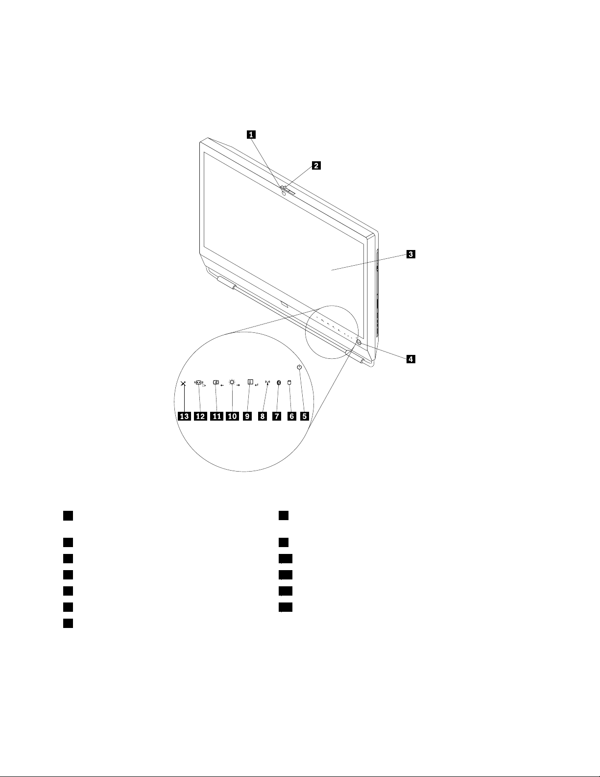
Frontview
Figure1“Frontcontrolandpartlocations”onpage8showsthelocationsofthecontrolsandpartsonthe
frontofyourcomputer.
Figure1.Frontcontrolandpartlocations
1 Integratedcamerawithmicrophone(MIC)
(availableinsomemodels)
2 Integratedcameraon/offbutton 9 Menu/Enter
3 Liquidcrystaldisplay(LCD)panel 10 Brightnesscontrol/Right
4 Powerswitch
5 Powerindicator
6 Harddiskdriveactivityindictor
7 Bluetoothactivityindicator
8 Wirelessactivityindicator
11 Imagesetupcontrol/Left
12 Monitormodecontrol/Exit
13 Microphonemute/oncontrol
Usingyourcomputerinmonitormode
Yourcomputercanworkintwomodes:computermodeormonitormode.Thissectionprovidesinstructions
onhowtouseyourcomputerinmonitormode.
8ThinkCentreUserGuide
Page 17
Touseyourcomputerinmonitormode,youneedtohaveasecondcomputer.ConnectoneendoftheVGA
cabletotheVGAINconnectorontherearofyourcomputer,andtheotherendtotheVGAconnectoron
thesecondcomputer.Usethemonitormodecontrolonthefrontofyourcomputertoswitchyour
computerbetweencomputermodeandmonitormode.
Thefollowingtableshowsthefunctionsofeachcontrolwhenyourcomputerworksincomputermode
ormonitormode.
IconControlDescription
Menu
Enter
BrightnesscontrolAdjustoverallmonitorbrightness.
RightMovetotheright.
ImagesetupcontrolAutomaticallyoptimizetheimage.
LeftMovetotheleft.
Cancel/ExitCancelanoperationorexitthemainOSDmenu.
Monitormodecontrol
OpenthemainOn-ScreenDisplay(OSD)menu.
Conrmaselection.
Switchyourcomputerbetweencomputermodeandmonitormode.
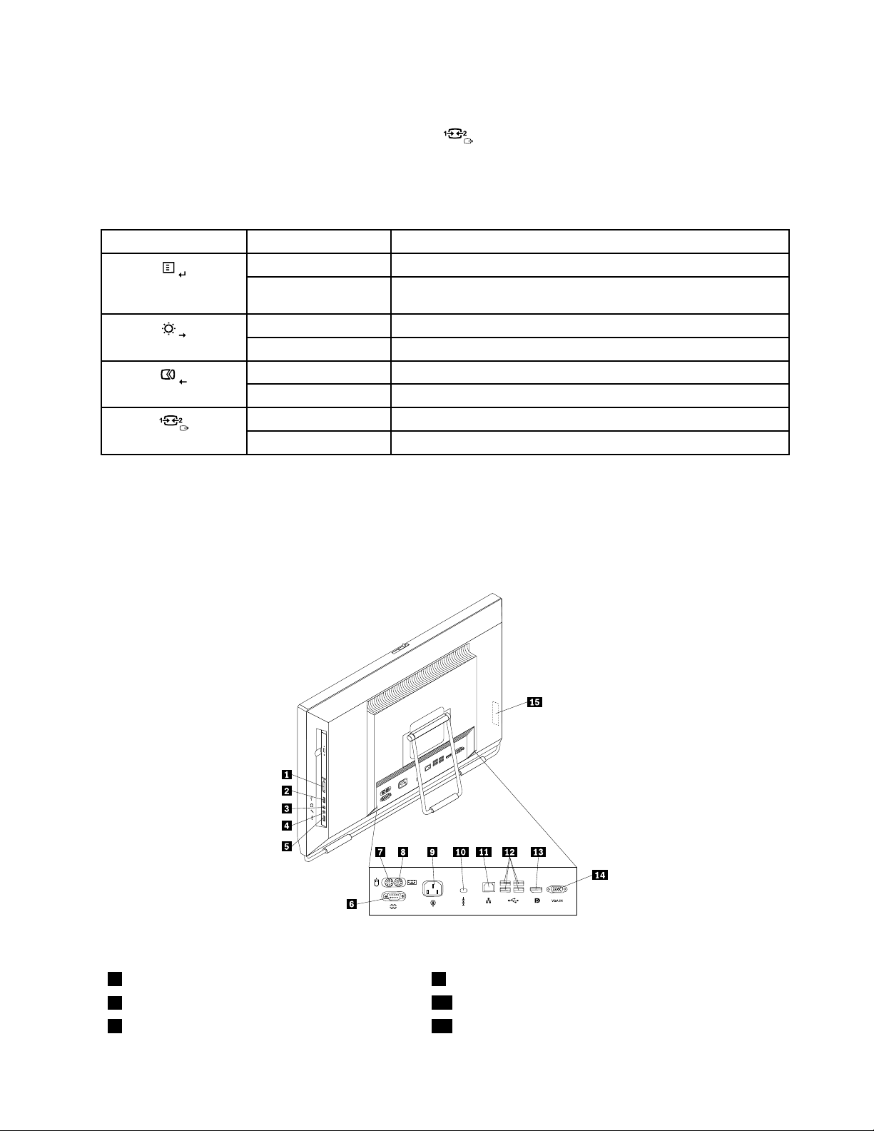
Rearview
Figure2“Rearconnectorlocations”onpage9showsthelocationsoftheconnectorsontherearofyour
computer.Someconnectorsontherearofyourcomputerarecolor-codedtohelpyoudeterminewhereto
connectthecablesonyourcomputer.
Figure2.Rearconnectorlocations
1Cardreader(availableinsomemodels)
2USBconnector
3Headphoneconnector11Ethernetconnector
9Powercordconnector
10Integratedcablelockslot
Chapter1.Productoverview9
Page 18

4Microphoneconnector
5USBconnector
6Serialport(availableinsomemodels)14VGAINconnector
7PS/2mouseconnector(availableinsomemodels)15ExpressCardslot(availableinsomemodels)
8PS/2keyboardconnector(availableinsome
12USBconnectors(4)
13DisplayPortoutconnector
models)
ConnectorDescription
DisplayPortoutconnector
Usedtoattachahigh-performancemonitor,adirect-drivemonitor,orotherdevices
thatuseaDisplayPortconnector.
Ethernetconnector
UsedtoattachanEthernetcableforalocalareanetwork(LAN).
Note:TooperatethecomputerwithinFCCClassBlimits,useaCategory5Ethernet
cable.
MicrophoneconnectorUsedtoattachamicrophonetoyourcomputerwhenyouwanttorecordsoundor
ifyouusespeech-recognitionsoftware.
PS/2keyboardconnector
UsedtoattachakeyboardthatusesaPS/2keyboardconnector.
(optional)
PS/2mouseconnector
(optional)
Serialport(optional)
Usedtoattachamouse,atrackball,orotherpointingdevicesthatuseaPS/2mouse
connector.
Usedtoattachanexternalmodem,aserialprinter,orotherdevicesthatusea9-pin
serialport.
USBconnectorUsedtoattachadevicethatrequiresaUSBconnector,suchasaUSBkeyboard,aUSB
mouse,aUSBscanner,oraUSBprinter.IfyouhavemorethaneightUSBdevices,you
canpurchaseaUSBhub,whichyoucanusetoconnectadditionalUSBdevices.
VGAINconnectorUsedtoconnectyourcomputertoaVGAmonitorconnectoronasecondcomputerso
thatyoucanuseyourcomputerinmonitormode.
10ThinkCentreUserGuide
Page 19
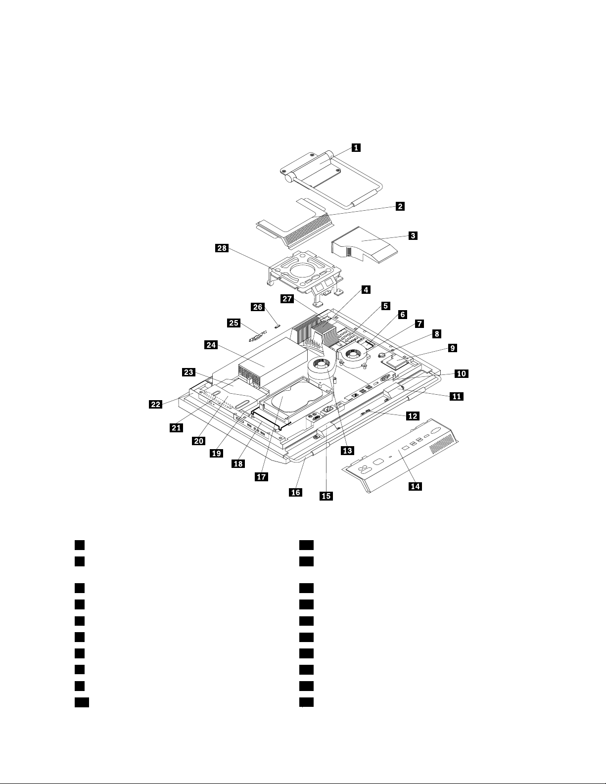
Componentlocations
Figure3“Componentlocations”onpage11showsthelocationsofthevariouscomponentsinyour
computer.T oremovethecomputercoverandaccesstheinsideofthecomputer,see“Removingthe
computercover”onpage15
.
Figure3.Componentlocations
1Framestand15Internalspeaker
2VideoElectronicsStandardsAssociation(VESA)
16Framefoot
framecover
3Fanduct17Harddiskdrive
4Heatsink
5Memorymodules(2)19Cardreader*
6WI-FIcard*
7Microprocessorfan
8Battery
9ExpressCard*23Opticaldrive*
10RearI/Oassembly
18RightI/Oassembly
20Opticaldrivebay
21Inverter
22Computermainbracket
24Powersupply
Chapter1.Productoverview11
Page 20
11Internalspeaker25Integratedcamerawithmicrophone*
12Bluetoothmodule*26Ambientlightsensor*
13Systemfan
14RearI/Oassemblycover28VESAframe
27Multi-touchboard*
Notes:
1.*denotesoptionalparts,whichareavailableinsomemodels.
2.Y ourcomputermightcomewithaframestandoraliftstand.Formoreinformationabouttheliftstand,
see“Removingorreinstallingtheliftstand”onpage17
.
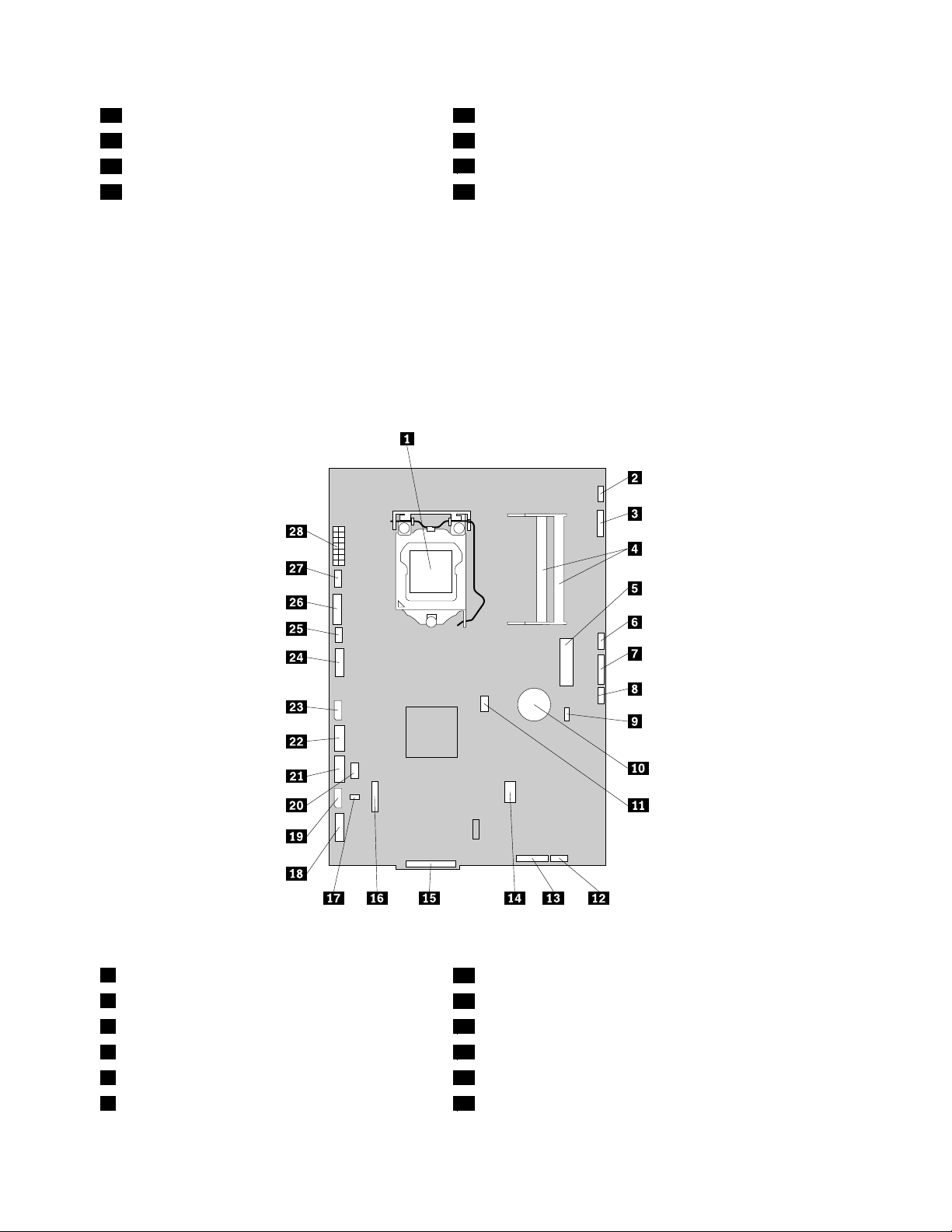
Systemboardpartandconnectorlocations
Figure4“Systemboardpartandconnectorlocations”onpage12showsthelocationsofthepartsand
connectorsonthesystemboard.
Figure4.Systemboardpartandconnectorlocations
1Microprocessor
2Multi-touchboardcableconnector
3Integratedcameracableconnector17Thermalsensorconnector
4Memoryslots(2)18RightI/Oassemblycableconnector
5MiniPCIExpressslot
6Ambientlightsensorcableconnector
15RearI/Oassemblyconnector
16COMconnector
19Harddiskdrivepowerconnector
20PS/2keyboardandmouseconnector
12ThinkCentreUserGuide
Page 21

7Bluetoothmodulecableconnector
8Wirelesskeyboardandmouseconnector
9ClearComplementaryMetalOxideSemiconductor
21SATAconnector
22SATAconnector
23Opticaldrivepowerconnector
(CMOS)/Recoveryjumper
10Battery
11Microprocessorfanconnector
12Internalspeakercableconnector26Inverterconnector
13Powerswitchcableconnector
14ExpressCardconnector
24Low-voltagedifferentialsignaling(LVDS)cableconnector
25Systemfanconnector
27Powersupplyfanconnector
28Powersupplyconnector
Chapter1.Productoverview13
Page 22

14ThinkCentreUserGuide
Page 23

Chapter2.Installingorreplacinghardware
Thischapterprovidesinstructionsonhowtoinstallorreplacehardwareforyourcomputer.
Thischaptercontainsthefollowingtopics:
•“Installingorreplacinghardware”onpage15
•“Obtainingdevicedrivers”onpage53
•“Basicsecurityfeatures”onpage53
Installingorreplacinghardware
Thissectionprovidesinstructionsonhowtoinstallorreplacehardwareforyourcomputer.Youcanmaintain
yourcomputerorexpandthecapabilitiesofyourcomputerbyinstallingorreplacinghardware.
Notes:
1.UseonlycomputerpartsprovidedbyLenovo.
2.Wheninstallingorreplacinganoption,usetheappropriateinstructionsinthissectionalongwiththe
instructionsthatcomewiththeoption.
Installingexternaloptions
Youcaninstallexternaloptionstoyourcomputer,suchasexternalspeakers,aprinter,orascanner.For
someexternaloptions,youmustinstalladditionalsoftwareinadditiontomakingthephysicalconnection.
Whenyouinstallanexternaloption,see“Locatingcomputercontrols,connectors,andparts”onpage7to
identifytherequiredconnector.Then,usetheinstructionsthatcomewiththeoptiontohelpyoumakethe
connectionandinstallanysoftwareordevicedriversthatarerequiredfortheoption.
Installingacomputerwallmount
CAUTION:
Ifyouwishtoperformaselfinstallationofawallmountingunitforthisproduct,Lenovorecommends
thatyouselectawallmountproductthatiscertiedbyUnderwritersLaboratories(UL),Intertek(ETL),
theCanadianStandardsAssociation(CSANRTL),TUVRheinlandofNorthAmerica(TUVUS),orany
othersafetytestlaboratorythatisrecognizedbytheUnitedStatesOccupationalSafetyandHealth
Administration(OSHA).T oavoidtheriskofpersonalinjuryordamagetoequipment,selfinstallers
shouldensurethattheweightbearingcapacityofthewallmountproductisratedabove12kg(26.5
lbs),sothatitcansupportthemachineforlongtimeoperationsafely.
YourcomputersupportsVESAstandard100mm×100mm(3.94inches×3.94inches)wallmounts.For
propermounting,usefourscrewsofthefollowingspecications:
Diameter×Pitch×Length:4mm×0.7mm×10mm(0.16inch×0.03inch×0.39inch)
Note:Wheninstallingacomputerwallmount,makesurethatyouleaveatleasta60mm(2.36inches)space
betweenthewallandyourcomputerforeasyaccesstotheconnectorsontherearofyourcomputer.
Removingthecomputercover
Attention:
Donotopenyourcomputerorattemptanyrepairbeforereadingandunderstandingthe“Importantsafetyinformation”
intheThinkCentreSafetyandWarrantyGuidethatcamewithyourcomputer.ToobtainacopyoftheThinkCentre
SafetyandWarrantyGuide,goto:
http://www.lenovo.com/support
©CopyrightLenovo,2011
15
Page 24
Thissectionprovidesinstructionsonhowtoremovethecomputercover.
CAUTION:
Turnoffthecomputerandwaitthreetoveminutestoletthecomputercoolbeforeremovingthe
computercover.
Toremovethecomputercover,dothefollowing:
1.Removeallmediafromthedrivesandturnoffallattacheddevicesandthecomputer.Then,disconnect
allpowercordsfromelectricaloutletsanddisconnectallcablesthatareconnectedtothecomputer.
2.Placeasoft,cleantowelorclothonthedeskorsurface.Holdthesidesofyourcomputerandgentlylay
itdownsothatthescreenisagainstthesurfaceandthecoverisfacingup.
3.Removeanylockingdevicethatsecuresthecomputercover,suchasanintegratedcablelock.See
“Integratedcablelock”onpage53.
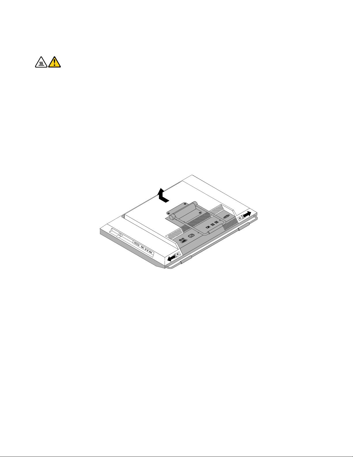
4.Pressthetwocover-releasebuttonsonthecomputercoverasshown,slidethecomputercovertoward
thetopofthecomputer,andthenliftthecomputercoveruptoremoveitfromthechassis.
Figure5.Removingthecomputercover
Removingorreinstallingtheframestand
Yourcomputermightcomewithaframestandoraliftstand.Thissectionprovidesinstructionsonhowto
removeorreinstalltheframestand.Forinformationabouttheliftstand,see“Removingorreinstallingthe
liftstand”onpage17
Toremoveorreinstalltheframestand,dothefollowing:
1.Removeallmediafromthedrivesandturnoffallattacheddevicesandthecomputer.Then,disconnect
allpowercordsfromelectricaloutletsanddisconnectallcablesthatareconnectedtothecomputer.
2.Placeasoft,cleantowelorclothonthedeskorsurface.Holdthesidesofyourcomputerandgentlylay
itdownsothatthescreenisagainstthesurfaceandthecoverisfacingup.
16ThinkCentreUserGuide
.
Page 25
3.Removethefourscrewsthatsecuretheframestand.Keepthefourscrews,andputthemaside.You
willneedthemwheninstallingtheframestand.
Figure6.Removingtheframestand
4.Lifttheframestandoffthecomputerandputitinasafeplace.
5.T oreinstalltheframestand,positiontheframestandsothatthefourscrewholesalignwiththoseinthe
computerVESAframeandtheninstallthefourscrewstosecuretheframestand.
Whattodonext:
•T oworkwithanotherpieceofhardware,gototheappropriatesection.
•T ocompletetheinstallationorreplacement,goto“Completingthepartsreplacement”onpage52.
Removingorreinstallingtheliftstand
Yourcomputermightcomewithaliftstandoraframestand.Thissectionprovidesinstructionsonhow
toremoveorreinstalltheliftstand.Forinformationabouttheframestand,see“Removingorreinstalling
theframestand”onpage16.
Toremoveorreinstalltheliftstand,dothefollowing:
1.Removeallmediafromthedrivesandturnoffallattacheddevicesandthecomputer.Then,disconnect
allpowercordsfromelectricaloutletsanddisconnectallcablesthatareconnectedtothecomputer.
2.Placeasoft,cleantowelorclothonthedeskorsurface.Holdthesidesofyourcomputerandgentlylay
itdownsothatthescreenisagainstthesurfaceandthecoverisfacingup.
Chapter2.Installingorreplacinghardware17
Page 26
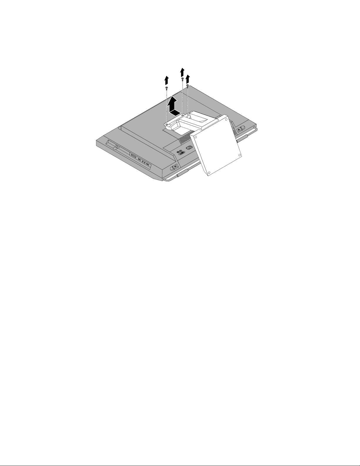
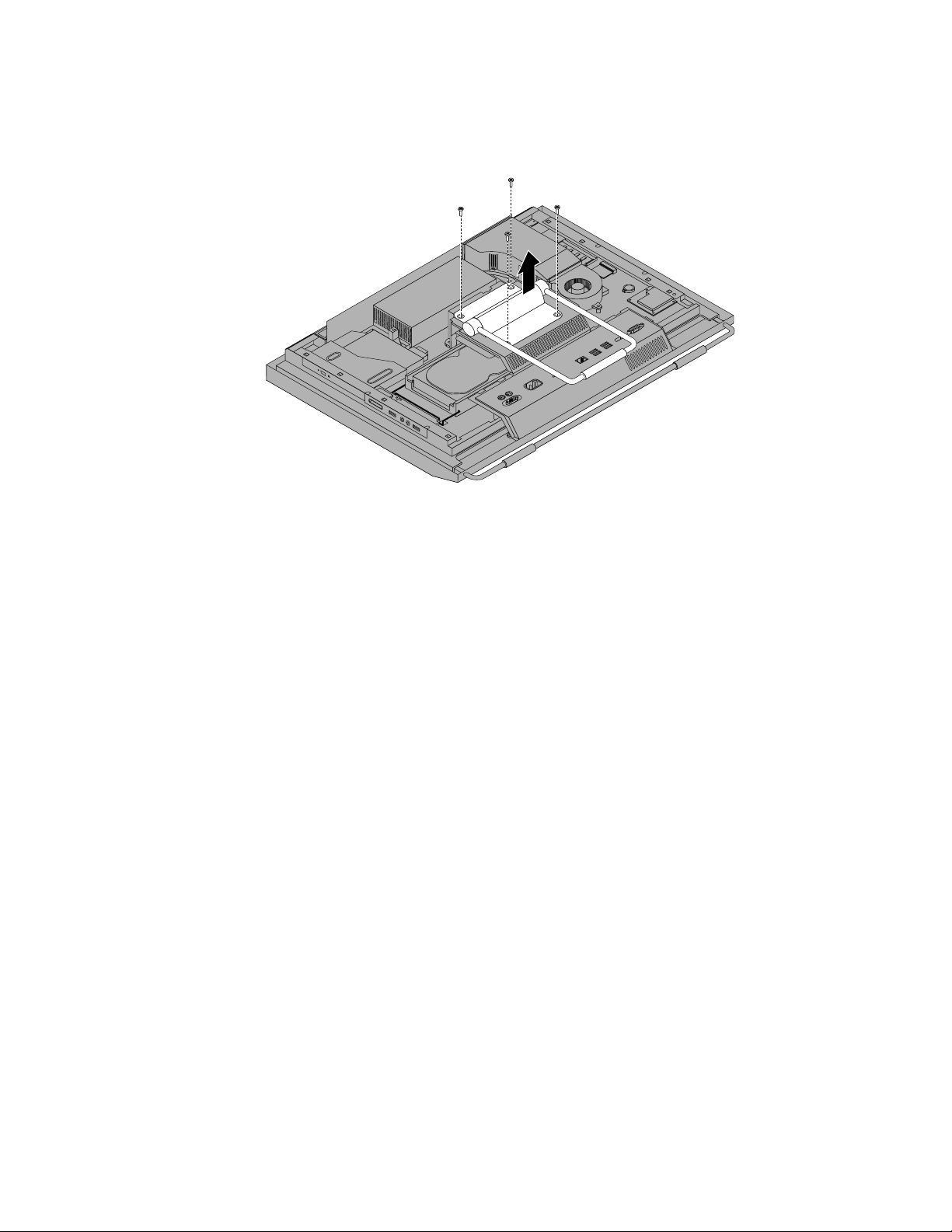
3.Removethethreescrewsthatsecuretheliftstand.Keepthethreescrews,andputthemaside.Youwill
needthemwheninstallingtheliftstand.Removetheliftstandfromthecomputer.
Figure7.Removingtheliftstand
18ThinkCentreUserGuide
Page 27
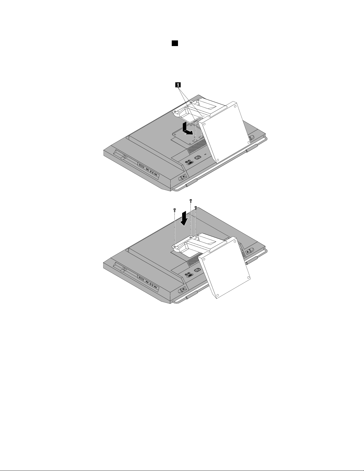
4.T oreinstalltheliftstand,insertthetwotabs1ontheliftstandintothecorrespondingholesinthe
computerVESAframe,andthenslidetheliftstandtowardthebottomofthecomputer.Alignthethree
screwholesintheliftstandwiththoseinthecomputerVESAframeandtheninstallthethreescrewsto
securetheliftstand.
Figure8.Reinstallingtheliftstand
Whattodonext:
•T oworkwithanotherpieceofhardware,gototheappropriatesection.
•T ocompletetheinstallationorreplacement,goto“Completingthepartsreplacement”onpage52.
RemovingorreinstallingtherearI/Oassemblycover
ThissectionprovidesinstructionsonhowtoremoveorreinstalltherearI/Oassemblycover.
ToremoveorreinstalltherearI/Oassemblycover,dothefollowing:
1.Removeallmediafromthedrivesandturnoffallattacheddevicesandthecomputer.Then,disconnect
allpowercordsfromelectricaloutletsanddisconnectallcablesthatareconnectedtothecomputer.
2.Placeasoft,cleantowelorclothonthedeskorsurface.Holdthesidesofyourcomputerandgentlylay
itdownsothatthescreenisagainstthesurfaceandthecoverisfacingup.
Chapter2.Installingorreplacinghardware19
Page 28
3.Removethecomputercover.See“Removingthecomputercover”onpage15.
4.LocatetherearI/Oassemblycover.See“Componentlocations”onpage11.
5.CarefullyreleasethebottomoftherearI/Oassemblycoverfromthecomputerfrontbezelandthen
releasethetopoftherearI/OassemblycoverfromthecomputerVESAframecover.
Figure9.RemovingtherearI/Oassemblycover
6.T oreinstalltherearI/Oassemblycover,engagethebottomoftherearI/Oassemblycoverwiththe
computerfrontbezelandthenpressthetopoftherearI/Oassemblycoverdownwarduntilitsnaps
intoplace.
Whattodonext:
•T oworkwithanotherpieceofhardware,gototheappropriatesection.
•T ocompletetheinstallationorreplacement,goto“Completingthepartsreplacement”onpage52.
RemovingorreinstallingtheVESAframecover
ToremoveorreinstalltheVESAframecover,dothefollowing:
1.Removeallmediafromthedrivesandturnoffallattacheddevicesandthecomputer.Then,disconnect
allpowercordsfromelectricaloutletsanddisconnectallcablesthatareconnectedtothecomputer.
2.Placeasoft,cleantowelorclothonthedeskorsurface.Holdthesidesofyourcomputerandgentlylay
itdownsothatthescreenisagainstthesurfaceandthecoverisfacingup.
3.Removethecomputercover.See“Removingthecomputercover”onpage15.
4.RemovetherearI/OassemblycoverfromtherearI/Oassembly.See“Removingorreinstallingthe
rearI/Oassemblycover”onpage19.
5.Removetheframestandorliftstand.See“Removingorreinstallingtheframestand”onpage16or
“Removingorreinstallingtheliftstand”onpage17
.
20ThinkCentreUserGuide
Page 29
6.RemovethescrewthatsecurestheVESAframecover,slidetheVESAframecovertothebottomof
thecomputer,andthenliftituptoremoveitfromtheVESAframe.
Figure10.RemovingtheVESAframecover
7.T oreinstalltheVESAframecover,alignthescrewholeintheVESAframecoverwiththecorresponding
holeintheVESAframeandtheninstallthescrewtosecuretheVESAframecover.
Whattodonext:
•T oworkwithanotherpieceofhardware,gototheappropriatesection.
•T ocompletetheinstallationorreplacement,goto“Completingthepartsreplacement”onpage52.
RemovingorreinstallingtheVESAframe
ToremoveorreinstalltheVESAframe,dothefollowing:
1.Removeallmediafromthedrivesandturnoffallattacheddevicesandthecomputer.Then,disconnect
allpowercordsfromelectricaloutletsanddisconnectallcablesthatareconnectedtothecomputer.
2.Placeasoft,cleantowelorclothonthedeskorsurface.Holdthesidesofyourcomputerandgentlylay
itdownsothatthescreenisagainstthesurfaceandthecoverisfacingup.
3.Removethecomputercover.See“Removingthecomputercover”onpage15.
4.RemovetherearI/OassemblycoverfromtherearI/Oassembly.See“Removingorreinstallingthe
rearI/Oassemblycover”onpage19.
5.Removetheframestandorliftstand.See“Removingorreinstallingtheframestand”onpage16or
“Removingorreinstallingtheliftstand”onpage17
6.RemovetheVESAframecover.See“RemovingorreinstallingtheVESAframecover”onpage20.
7.Disconnectthethermalsensorcablefromthesystemboard.See“Systemboardpartandconnector
locations”onpage12
.
.
Chapter2.Installingorreplacinghardware21
Page 30

8.Removethefourscrews1thatsecuretheVESAframetothecomputermainbracketandthenlift
theVESAframeoffthecomputermainbracket.
Figure11.RemovingthecomputerVESAframe
9.T oreinstallthecomputerVESAframe,positiontheVESAframeonthecomputermainbracketandalign
thescrewholesintheVESAframewiththoseinthecomputermainbracket.
10.ReinstallthefourscrewstosecuretheVESAframetothecomputermainbracket.
11.Reconnectthethermalsensorcabletothesystemboard.See“Systemboardpartandconnector
locations”onpage12.
12.ReinstalltheVESAframecover.See“RemovingorreinstallingtheVESAframecover”onpage20.
Whattodonext:
•T oworkwithanotherpieceofhardware,gototheappropriatesection.
•T ocompletetheinstallationorreplacement,goto“Completingthepartsreplacement”onpage52
Installingorreplacingamemorymodule
Attention:
Donotopenyourcomputerorattemptanyrepairbeforereadingandunderstandingthe“Importantsafetyinformation”
intheThinkCentreSafetyandWarrantyGuidethatcamewithyourcomputer.ToobtainacopyoftheThinkCentre
SafetyandWarrantyGuide,goto:
http://www.lenovo.com/support
Thissectionprovidesinstructionsonhowtoinstallorreplaceamemorymodule.
.
YourcomputerhastwoslotsforinstallingorreplacingDDR3SODIMMs(smalloutlinedualinlinememory
modules).Wheninstallingorreplacingamemorymodule,use1GB,2GBor4GBDDR3SODIMMsinany
combinationuptoamaximumof8GBofsystemmemory.
Toinstallorreplaceamemorymodule,dothefollowing:
22ThinkCentreUserGuide
Page 31

1.Removeallmediafromthedrivesandturnoffallattacheddevicesandthecomputer.Then,disconnect
allpowercordsfromelectricaloutletsanddisconnectallcablesthatareconnectedtothecomputer.
2.Placeasoft,cleantowelorclothonthedeskorsurface.Holdthesidesofyourcomputerandgentlylay
itdownsothatthescreenisagainstthesurfaceandthecoverisfacingup.
3.Removethecomputercover.See“Removingthecomputercover”onpage15.
4.Locatethememoryslots.See“Componentlocations”onpage11.
5.Opentheretainingclips.Ifyouarereplacinganoldmemorymodule,opentheretainingclipsand
removetheoldmemorymodule,asshown:
Figure12.Removingthememorymodule
6.Insertthenotchedend2ofthenewmemorymoduleintotheslot1.Pressthememorymodule
rmlyandpivotthememorymoduleuntilitsnapsintoplace.Makesurethatthememorymoduleis
securedintheslotanddoesnotmoveeasily.
Figure13.Installingamemorymodule
Whattodonext:
•T oworkwithanotherpieceofhardware,gototheappropriatesection.
•T ocompletetheinstallationorreplacement,goto“Completingthepartsreplacement”onpage52.
Chapter2.Installingorreplacinghardware23
Page 32

Replacingthebattery
Attention:
Donotopenyourcomputerorattemptanyrepairbeforereadingandunderstandingthe“Importantsafetyinformation”
intheThinkCentreSafetyandWarrantyGuidethatcamewithyourcomputer.ToobtainacopyoftheThinkCentre
SafetyandWarrantyGuide,goto:
http://www.lenovo.com/support
Thissectionprovidesinstructionsonhowtoreplacethebattery.
Yourcomputerhasaspecialtypeofmemorythatmaintainsthedate,time,andsettingsforbuilt-infeatures,
suchasparallel-portassignments(conguration).Abatterykeepstheinformationactivewhenyouturn
offthecomputer.
Thebatterynormallyrequiresnochargingormaintenancethroughoutitslife.However,ifthebatteryfails,
thedate,time,andcongurationinformation(includingpasswords)arelost.Anerrormessagewillbe
displayedwhenyouturnonthecomputer.
Refertothe“Lithiumbatterynotice”intheThinkCentreSafetyandWarrantyGuideforinformationabout
replacinganddisposingofthebattery.
Toreplacethebattery,dothefollowing:
1.Removeallmediafromthedrivesandturnoffallattacheddevicesandthecomputer.Then,disconnect
allpowercordsfromelectricaloutletsanddisconnectallcablesthatareconnectedtothecomputer.
2.Placeasoft,cleantowelorclothonthedeskorsurface.Holdthesidesofyourcomputerandgentlylay
itdownsothatthescreenisagainstthesurfaceandthecoverisfacingup.
3.Removethecomputercover.See“Removingthecomputercover”onpage15.
4.Locatethebatteryonthesystemboard.See“Systemboardpartandconnectorlocations”onpage12.
5.Removethebattery.
Figure14.Removingthebattery
24ThinkCentreUserGuide
Page 33

6.Installanewbattery.
Figure15.Installinganewbattery
7.Reinstallthecomputercoverandconnectthecables.See“Completingthepartsreplacement”on
page52.
Note:Whenthecomputeristurnedonforthersttimeafterreplacingthebattery,anerrormessage
mightbedisplayed.Thisisnormalafterreplacingthebattery.
8.T urnonthecomputerandallattacheddevices.
9.UsetheSetupUtilityprogramtosetthedate,time,andanypasswords.SeeChapter4“UsingtheSetup
Utilityprogram”onpage63.
Whattodonext:
•T oworkwithanotherpieceofhardware,gototheappropriatesection.
•T ocompletetheinstallationorreplacement,goto“Completingthepartsreplacement”onpage52
.
Replacingtheharddiskdrive
Attention:
Donotopenyourcomputerorattemptanyrepairbeforereadingandunderstandingthe“Importantsafetyinformation”
intheThinkCentreSafetyandWarrantyGuidethatcamewithyourcomputer.ToobtainacopyoftheThinkCentre
SafetyandWarrantyGuide,goto:
http://www.lenovo.com/support
Thissectionprovidesinstructionsonhowtoreplacetheharddiskdrive.
Toreplacetheharddiskdrive,dothefollowing:
1.Removeallmediafromthedrivesandturnoffallattacheddevicesandthecomputer.Then,disconnect
allpowercordsfromelectricaloutletsanddisconnectallcablesthatareconnectedtothecomputer.
2.Removethecomputercover.See“Removingthecomputercover”onpage15.
3.Locatetheharddiskdriveinthecomputer.See“Componentlocations”onpage11.
Chapter2.Installingorreplacinghardware25
Page 34

4.Pullthehandle1oftheharddiskdrivebracketupwardandthenslidetheharddiskdriveoutwardto
removeitfromtheharddiskdrivebay.
Figure16.Removingtheharddiskdrive
5.Flexthesidesoftheharddiskdrivebracketproperlytoremovetheharddiskdriveoutofthebracket.
6.T oinstallthenewharddiskdriveintothebracket,exthebracketandalignpin1,pin2,pin3,and
pin4onthebracketwiththecorrespondingholesintheharddiskdrive.Donottouchthecircuit
board5onthebottomoftheharddiskdrive.
Figure17.Installingtheharddiskdriveintothebracket
26ThinkCentreUserGuide
Page 35

7.Alignthefourpins1ontheharddiskdrivebracketwiththecorrespondingslotsintheharddisk
drivebay.
Figure18.Installingtheharddiskdrive
8.Slidethenewharddiskdrivewiththebracketintotheharddiskdrivebay.Pressthehandleofthehard
diskdrivebracketdownwarduntilitissecuredbythetwotabs1.
Figure19.Installingtheharddiskdrive
Whattodonext:
•T oworkwithanotherpieceofhardware,gototheappropriatesection.
•T ocompletetheinstallationorreplacement,goto“Completingthepartsreplacement”onpage52.
Chapter2.Installingorreplacinghardware27
Page 36

Replacingtheopticaldrive
Attention:
Donotopenyourcomputerorattemptanyrepairbeforereadingandunderstandingthe“Importantsafetyinformation”
intheThinkCentreSafetyandWarrantyGuidethatcamewithyourcomputer.ToobtainacopyoftheThinkCentre
SafetyandWarrantyGuide,goto:
http://www.lenovo.com/support
Thissectionprovidesinstructionsonhowtoreplacetheopticaldrive.
Note:Theopticaldriveisavailableonlyinsomemodels.
Toreplacetheopticaldrive,dothefollowing:
1.Removeallmediafromthedrivesandturnoffallattacheddevicesandthecomputer.Then,disconnect
allpowercordsfromelectricaloutletsanddisconnectallcablesthatareconnectedtothecomputer.
2.Placeasoft,cleantowelorclothonthedeskorsurface.Holdthesidesofyourcomputerandgentlylay
itdownsothatthescreenisagainstthesurfaceandthecoverisfacingup.
3.Removethecomputercover.See“Removingthecomputercover”onpage15.
4.Locatetheopticaldrive.See“Componentlocations”onpage11.
5.Presstheopticaldrivereleasebutton1towardthetopofthecomputerandthenslidetheopticaldrive
outoftheopticaldrivebay.
Figure20.Removingtheopticaldrive
28ThinkCentreUserGuide
Page 37

6.T oinstallanewopticaldrive,slidethenewopticaldriveintotheopticaldrivebayuntilitsnapsinto
position.
Figure21.Installingtheopticaldrive
Whattodonext:
•T oworkwithanotherpieceofhardware,gototheappropriatesection.
•T ocompletetheinstallationorreplacement,goto“Completingthepartsreplacement”onpage52.
Replacingtheheatsink
Attention:
Donotopenyourcomputerorattemptanyrepairbeforereadingandunderstandingthe“Importantsafetyinformation”
intheThinkCentreSafetyandWarrantyGuidethatcamewithyourcomputer.ToobtainacopyoftheThinkCentre
SafetyandWarrantyGuide,goto:
http://www.lenovo.com/support
Thissectionprovidesinstructionsonhowtoreplacetheheatsink.
CAUTION:
Theheatsinkmightbeveryhot.Turnoffthecomputerandwaitthreetoveminutestoletthe
computercoolbeforeremovingthecomputercover .
Toreplacetheheatsink,dothefollowing:
1.Removeallmediafromthedrivesandturnoffallattacheddevicesandthecomputer.Then,disconnect
allpowercordsfromelectricaloutletsanddisconnectallcablesthatareconnectedtothecomputer.
2.Placeasoft,cleantowelorclothonthedeskorsurface.Holdthesidesofyourcomputerandgentlylay
itdownsothatthescreenisagainstthesurfaceandthecoverisfacingup.
3.Removethecomputercover.See“Removingthecomputercover”onpage15.
4.Locatetheheatsinkonthesystemboard.See“Componentlocations”onpage11.
Chapter2.Installingorreplacinghardware29
Page 38

5.Removethefanductbypressingthetwotabs1inwardandthenpivotingthefanductupward.
Figure22.Removingthefanduct
30ThinkCentreUserGuide
Page 39

6.Followthissequencetoremovethefourscrewsthatsecuretheheatsinktothesystemboard:
a.Partiallyremovescrew1,thenfullyremovescrew2,andthenfullyremovescrew1.
b.Partiallyremovescrew3,thenfullyremovescrew4,andthenfullyremovescrew3.
Note:Carefullyremovethefourscrewsfromthesystemboardtoavoidanypossibledamagetothe
systemboard.Thefourscrewscannotberemovedfromtheheatsink.
Figure23.Removingtheheatsink
7.Liftthefailingheatsinkoffthesystemboard.
Notes:
a.Youmighthavetogentlytwisttheheatsinktofreeitfromthemicroprocessor.
b.Donottouchthethermalgreasewhilehandlingtheheatsink.
8.Positionthenewheatsinkonthesystemboardsothatthefourscrewsarealignedwiththe
correspondingholesinthesystemboard.
9.Followthissequencetoinstallthefourscrewstosecuretheheatsink,asshowninFigure23“Removing
theheatsink”onpage31.
a.Partiallytightenscrew1,thenfullytightenscrew2,andthenfullytightenscrew1.
b.Partiallytightenscrew3,thenfullytightenscrew4,andthenfullytightenscrew3.
10.T oreinstallthefanduct,positionthefanductontheheatsinkandthenpressthefanductdownward
untilthetwotabsonthefanductaresecuredintoplace.
Whattodonext:
•T oworkwithanotherpieceofhardware,gototheappropriatesection.
•T ocompletetheinstallationorreplacement,goto“Completingthepartsreplacement”onpage52.
Chapter2.Installingorreplacinghardware31
Page 40

Replacingthemicroprocessor
Attention:
Donotopenyourcomputerorattemptanyrepairbeforereadingandunderstandingthe“Importantsafetyinformation”
intheThinkCentreSafetyandWarrantyGuidethatcamewithyourcomputer.ToobtainacopyoftheThinkCentre
SafetyandWarrantyGuide,goto:
http://www.lenovo.com/support
Thissectionprovidesinstructionsonhowtoreplacethemicroprocessor.
CAUTION:
Theheatsinkandmicroprocessormightbeveryhot.T urnoffthecomputerandwaitthreetove
minutestoletthecomputercoolbeforeremovingthecomputercover.
Toreplacethemicroprocessor,dothefollowing:
1.Removeallmediafromthedrivesandturnoffallattacheddevicesandthecomputer.Then,disconnect
allpowercordsfromelectricaloutletsanddisconnectallcablesthatareconnectedtothecomputer.
2.Placeasoft,cleantowelorclothonthedeskorsurface.Holdthesidesofyourcomputerandgentlylay
itdownsothatthescreenisagainstthesurfaceandthecoverisfacingup.
3.Removethecomputercover.See“Removingthecomputercover”onpage15.
4.Removethefanductandtheheatsinkfromthesystemboard.See“Replacingtheheatsink”onpage29.
5.Liftthesmallhandle1andopentheretainer2toaccessthemicroprocessor3.
6.Liftthemicroprocessorstraightupandoutofthesocket.SeeFigure24“Removingthemicroprocessor”
onpage33
.
Notes:
a.Yourmicroprocessorandsocketmightlookdifferentfromtheoneillustrated.
b.Notetheorientationofthemicroprocessorinthesocket.Youcaneitherlookforthesmalltriangle1
ononecornerofthemicroprocessorornotetheorientationofthenotches2onthemicroprocessor.
Thisisimportantwheninstallingthenewmicroprocessoronthesystemboard.
32ThinkCentreUserGuide
Page 41

c.Touchonlythesidesofthemicroprocessor.Donottouchthegoldcontactsonthebottom.
d.Donotdropanythingontothemicroprocessorsocketwhileitisexposed.Thesocketpinsmustbe
keptascleanaspossible.
Figure24.Removingthemicroprocessor
7.Makesurethatthesmallhandleisintheraisedpositionandthemicroprocessorretainerisfullyopen.
Chapter2.Installingorreplacinghardware33
Page 42

8.Holdthenewmicroprocessorandalignthenotches2onitwiththealignmentkeysinthe
microprocessorsocket,oralignthesmalltriangle1ononecornerofthenewmicroprocessorwiththe
correspondingbeveledcornerofthemicroprocessorsocket.
Figure25.Installingthemicroprocessor
9.Lowerthenewmicroprocessorstraightdownintothemicroprocessorsocketonthesystemboard.
10.Closethemicroprocessorretainerandlockitintopositionwiththesmallhandletosecurethenew
microprocessorinthesocket.
11.Reinstalltheheatsinkandthefanduct.See“Replacingtheheatsink”onpage29.
12.Reinstallanyotherpartsorreconnectanyothercablesyouremoved.
Whattodonext:
•T oworkwithanotherpieceofhardware,gototheappropriatesection.
•T ocompletetheinstallationorreplacement,goto“Completingthepartsreplacement”onpage52
ReplacingtheWI-FIcard
Attention:
Donotopenyourcomputerorattemptanyrepairbeforereadingandunderstandingthe“Importantsafetyinformation”
intheThinkCentreSafetyandWarrantyGuidethatcamewithyourcomputer.ToobtainacopyoftheThinkCentre
SafetyandWarrantyGuide,goto:
http://www.lenovo.com/support
ThissectionprovidesinstructionsonhowtoreplacetheWI-FIcard.
Note:TheWI-FIcardisavailableonlyinsomemodels.
.
ToreplacetheWI-FIcard,dothefollowing:
1.Removeallmediafromthedrivesandturnoffallattacheddevicesandthecomputer.Then,disconnect
allpowercordsfromelectricaloutletsanddisconnectallcablesthatareconnectedtothecomputer.
2.Placeasoft,cleantowelorclothonthedeskorsurface.Holdthesidesofyourcomputerandgentlylay
itdownsothatthescreenisagainstthesurfaceandthecoverisfacingup.
34ThinkCentreUserGuide
Page 43

3.Removethecomputercover.See“Removingthecomputercover”onpage15.
4.LocatetheWI-FIcardonthesystemboard.See“Componentlocations”onpage11.
5.DisconnectthetwocablesfromtheWI-FIcard.
6.CarefullyremovethetwoscrewsthatsecuretheWI-FIcardtothesystemboard.Then,pivottheWI-FI
cardupwardandlifttheWI-FIcardtoremoveitfromtheminiPCIExpressslot.
Figure26.RemovingtheWI-FIcard
7.InsertthenotchedendofthenewWI-FIcardintotheminiPCIExpressslot.PressthenewWI-FI
cardrmlyandthenpivottheWI-FIcardtoalignthescrewholesinthenewWI-FIcardwiththose
inthesystemboard.
8.InstallthetwoscrewstosecurethenewWI-FIcardtothesystemboard.
9.ConnectthetwocablestothenewWI-FIcard.
Whattodonext:
•T oworkwithanotherpieceofhardware,gototheappropriatesection.
•T ocompletetheinstallationorreplacement,goto“Completingthepartsreplacement”onpage52
ReplacingtheBluetoothmodule
Attention:
Donotopenyourcomputerorattemptanyrepairbeforereadingandunderstandingthe“Importantsafetyinformation”
intheThinkCentreSafetyandWarrantyGuidethatcamewithyourcomputer.ToobtainacopyoftheThinkCentre
SafetyandWarrantyGuide,goto:
http://www.lenovo.com/support
ThissectionprovidesinstructionsonhowtoreplacetheBluetoothmodule.
Note:TheBluetoothmoduleisavailableonlyinsomemodels.
.
Chapter2.Installingorreplacinghardware35
Page 44

ToreplacetheBluetoothmodule,dothefollowing:
1.Removeallmediafromthedrivesandturnoffallattacheddevicesandthecomputer.Then,disconnect
allpowercordsfromelectricaloutletsanddisconnectallcablesthatareconnectedtothecomputer.
2.Placeasoft,cleantowelorclothonthedeskorsurface.Holdthesidesofyourcomputerandgentlylay
itdownsothatthescreenisagainstthesurfaceandthecoverisfacingup.
3.Removethecomputercover.See“Removingthecomputercover”onpage15.
4.RemovetherearI/Oassemblycover.See“RemovingorreinstallingtherearI/Oassemblycover”
onpage19.
5.LocatetheBluetoothmoduleinthecomputer.See“Componentlocations”onpage11.
6.NotetheBluetoothmodulecableroutinganddisconnectthecablefromthesystemboard.
7.CarefullyreleasetheBluetoothmoduleandlifttheBluetoothmoduleoutofthecomputer.
Figure27.RemovingtheBluetoothmodule
8.PositionthenewBluetoothmoduleintothecomputerfrontbezelandthenpressthenewBluetooth
moduledownwarduntilitissecuredintoplace.
9.ConnectthenewBluetoothmodulecabletothesystemboard.See“Systemboardpartandconnector
locations”onpage12.
10.ReinstalltherearI/Oassemblycover.See“RemovingorreinstallingtherearI/Oassemblycover”
onpage19.
Whattodonext:
•T oworkwithanotherpieceofhardware,gototheappropriatesection.
•T ocompletetheinstallationorreplacement,goto“Completingthepartsreplacement”onpage52.
Replacingthemulti-touchboard
Attention:
Donotopenyourcomputerorattemptanyrepairbeforereadingandunderstandingthe“Importantsafetyinformation”
intheThinkCentreSafetyandWarrantyGuidethatcamewithyourcomputer.ToobtainacopyoftheThinkCentre
SafetyandWarrantyGuide,goto:
http://www.lenovo.com/support
Thissectionprovidesinstructionsonhowtoreplacethemulti-touchboard.
Note:Themulti-touchboardisavailableonlyinsomemodels.
36ThinkCentreUserGuide
Page 45

Toreplacethemulti-touchboard,dothefollowing:
1.Removeallmediafromthedrivesandturnoffallattacheddevicesandthecomputer.Then,disconnect
allpowercordsfromelectricaloutletsanddisconnectallcablesthatareconnectedtothecomputer.
2.Placeasoft,cleantowelorclothonthedeskorsurface.Holdthesidesofyourcomputerandgentlylay
itdownsothatthescreenisagainstthesurfaceandthecoverisfacingup.
3.Removethecomputercover.See“Removingthecomputercover”onpage15.
4.Locatethemulti-touchboardinthecomputer.See“Componentlocations”onpage11.
5.Notethemulti-touchboardcableroutinganddisconnectthethreemulti-touchboardcablesfrom
thesystemboardandthemulti-touchscreen.
6.Carefullyremovethetwoscrews1thatsecurethemulti-touchboardandthenliftthemulti-touch
boardoffthecomputermainbracket.
Figure28.Removingthemulti-touchboard
7.Alignthescrewholesinthenewmulti-touchboardwiththoseinthecomputermainbracketandthen
installthetwoscrewstosecurethemulti-touchboard.
8.Connectthenewmulti-touchboardcablestothesystemboardandthemulti-touchscreen.See
“Systemboardpartandconnectorlocations”onpage12.
Whattodonext:
•T oworkwithanotherpieceofhardware,gototheappropriatesection.
•T ocompletetheinstallationorreplacement,goto“Completingthepartsreplacement”onpage52
Replacingtheambientlightsensor
Attention:
Donotopenyourcomputerorattemptanyrepairbeforereadingandunderstandingthe“Importantsafetyinformation”
intheThinkCentreSafetyandWarrantyGuidethatcamewithyourcomputer.ToobtainacopyoftheThinkCentre
SafetyandWarrantyGuide,goto:
http://www.lenovo.com/support
Chapter2.Installingorreplacinghardware37
.
Page 46

Thissectionprovidesinstructionsonhowtoreplacetheambientlightsensor.
Note:Theambientlightsensorisavailableonlyinsomemodels.
Toreplacetheambientlightsensor,dothefollowing:
1.Removeallmediafromthedrivesandturnoffallattacheddevicesandthecomputer.Then,disconnect
allpowercordsfromelectricaloutletsanddisconnectallcablesthatareconnectedtothecomputer.
2.Placeasoft,cleantowelorclothonthedeskorsurface.Holdthesidesofyourcomputerandgentlylay
itdownsothatthescreenisagainstthesurfaceandthecoverisfacingup.
3.Removethecomputercover.See“Removingthecomputercover”onpage15.
4.Locatetheambientlightsensorinthecomputer.See“Componentlocations”onpage11.
5.Carefullyremovethetwoscrews1thatsecuretheambientlightsensorandthenlifttheambientlight
sensoroutofthecomputer.
Figure29.Removingtheambientlightsensor
6.Disconnecttheambientlightsensorcablefromthesystemboard.
7.Alignthescrewholesinthenewambientlightsensorwiththecorrespondingholesinthecomputer
andtheninstallthetwoscrewstosecuretheambientlightsensor.
8.Connectthenewambientlightsensorcabletothesystemboard.See“Systemboardpartand
connectorlocations”onpage12.
Whattodonext:
•T oworkwithanotherpieceofhardware,gototheappropriatesection.
•T ocompletetheinstallationorreplacement,goto“Completingthepartsreplacement”onpage52.
38ThinkCentreUserGuide
Page 47

ReplacingtheExpressCard
Attention:
Donotopenyourcomputerorattemptanyrepairbeforereadingandunderstandingthe“Importantsafetyinformation”
intheThinkCentreSafetyandWarrantyGuidethatcamewithyourcomputer.ToobtainacopyoftheThinkCentre
SafetyandWarrantyGuide,goto:
http://www.lenovo.com/support
ThissectionprovidesinstructionsonhowtoreplacetheExpressCard.
Note:TheExpressCardisavailableonlyinsomemodels.
ToreplacetheExpressCard,dothefollowing:
1.Removeallmediafromthedrivesandturnoffallattacheddevicesandthecomputer.Then,disconnect
allpowercordsfromelectricaloutletsanddisconnectallcablesthatareconnectedtothecomputer.
2.Placeasoft,cleantowelorclothonthedeskorsurface.Holdthesidesofyourcomputerandgentlylay
itdownsothatthescreenisagainstthesurfaceandthecoverisfacingup.
3.Removethecomputercover.See“Removingthecomputercover”onpage15.
4.LocatetheExpressCardinthecomputer.See“Componentlocations”onpage11.
5.Carefullyremovethefourscrews1thatsecuretheExpressCardtothesystemboardandthenliftit
offthesystemboard.
Figure30.RemovingtheExpressCard
6.ConnectthenewExpressCardtotheExpressCardconnectoronthesystemboard.Alignthescrew
holesinthenewExpressCardwiththecorrespondingholesinthesystemboardandtheninstallthefour
screwstosecurethenewExpressCard.
Chapter2.Installingorreplacinghardware39
Page 48

Whattodonext:
•T oworkwithanotherpieceofhardware,gototheappropriatesection.
•T ocompletetheinstallationorreplacement,goto“Completingthepartsreplacement”onpage52.
Replacingtheinternalspeakers
Attention:
Donotopenyourcomputerorattemptanyrepairbeforereadingandunderstandingthe“Importantsafetyinformation”
intheThinkCentreSafetyandWarrantyGuidethatcamewithyourcomputer.ToobtainacopyoftheThinkCentre
SafetyandWarrantyGuide,goto:
http://www.lenovo.com/support
Thissectionprovidesinstructionsonhowtoreplacetheinternalspeakers.
Toreplacetheinternalspeakers,dothefollowing:
1.Removeallmediafromthedrivesandturnoffallattacheddevicesandthecomputer.Then,disconnect
allpowercordsfromelectricaloutletsanddisconnectallcablesthatareconnectedtothecomputer.
2.Placeasoft,cleantowelorclothonthedeskorsurface.Holdthesidesofyourcomputerandgentlylay
itdownsothatthescreenisagainstthesurfaceandthecoverisfacingup.
3.Removethecomputercover.See“Removingthecomputercover”onpage15.
4.RemovetherearI/Oassemblycover.See“RemovingorreinstallingtherearI/Oassemblycover”
onpage19.
5.Locatetheinternalspeakersinthecomputer.See“Componentlocations”onpage11.
6.Notethelocationoftheinternalspeakercableconnection.Notetheroutingoftheinternalspeaker
cables.Disconnecttheinternalspeakercablesfromthesystemboard.
7.Removethetwoscrews1thatsecureeachinternalspeakertothefrontbezel,andthenremovethe
internalspeakersfromthecomputer.
Figure31.Removingtheinternalspeakers
40ThinkCentreUserGuide
Page 49

8.Routethenewinternalspeakercablesandthenpositionthenewinternalspeakersonthefrontbezelso
thatthetwoscrewholesineachinternalspeakeralignwiththoseinthefrontbezel.
9.Reinstallthetwoscrewstosecureeachoftheinternalspeakerstothefrontbezel.
10.Reconnecttheinternalspeakercablestothesystemboard.See“Systemboardpartandconnector
locations”onpage12.
11.ReinstalltherearI/Oassemblycover.See“RemovingorreinstallingtherearI/Oassemblycover”
onpage19.
Whattodonext:
•T oworkwithanotherpieceofhardware,gototheappropriatesection.
•T ocompletetheinstallationorreplacement,goto“Completingthepartsreplacement”onpage52.
Replacingtheintegratedcamerawithmicrophone
Attention:
Donotopenyourcomputerorattemptanyrepairbeforereadingandunderstandingthe“Importantsafetyinformation”
intheThinkCentreSafetyandWarrantyGuidethatcamewithyourcomputer.ToobtainacopyoftheThinkCentre
SafetyandWarrantyGuide,goto:
http://www.lenovo.com/support
Thissectionprovidesinstructionsonhowtoreplacetheintegratedcamerawithmicrophone.
Note:Theintegratedcamerawithmicrophoneisavailableonlyinsomemodels.
Toreplacetheintegratedcamerawithmicrophone,dothefollowing:
1.Removeallmediafromthedrivesandturnoffallattacheddevicesandthecomputer.Then,disconnect
allpowercordsfromelectricaloutletsanddisconnectallcablesthatareconnectedtothecomputer.
2.Placeasoft,cleantowelorclothonthedeskorsurface.Holdthesidesofyourcomputerandgentlylay
itdownsothatthescreenisagainstthesurfaceandthecoverisfacingup.
3.Removethecomputercover.See“Removingthecomputercover”onpage15.
4.Locatetheintegratedcamerawithmicrophoneinthecomputer.See“Componentlocations”onpage11.
5.Notetheroutingoftheintegratedcameracableandthendisconnecttheintegratedcameracablefrom
thesystemboard.See“Systemboardpartandconnectorlocations”onpage12.
Chapter2.Installingorreplacinghardware41
Page 50

6.Removethetwoscrews1thatsecuretheintegratedcamerawithmicrophonetothefrontbezel,and
thenremovetheintegratedcamerawithmicrophonefromthecomputer.
Figure32.Removingtheintegratedcamerawithmicrophone
7.Routethenewintegratedcameracableandthenpositionthenewintegratedcamerawithmicrophone
inplace.Alignthetwoscrewholesinthenewintegratedcamerawithmicrophonewiththoseinthe
frontbezel.
8.Reinstallthetwoscrewstosecurethenewintegratedcamerawithmicrophonetothefrontbezel.
9.Connecttheintegratedcameracabletothesystemboard.See“Systemboardpartandconnector
locations”onpage12.
Whattodonext:
•T oworkwithanotherpieceofhardware,gototheappropriatesection.
•T ocompletetheinstallationorreplacement,goto“Completingthepartsreplacement”onpage52.
Replacingthemicroprocessorfanassembly
Attention:
Donotopenyourcomputerorattemptanyrepairbeforereadingandunderstandingthe“Importantsafetyinformation”
intheThinkCentreSafetyandWarrantyGuidethatcamewithyourcomputer.ToobtainacopyoftheThinkCentre
SafetyandWarrantyGuide,goto:
http://www.lenovo.com/support
Thissectionprovidesinstructionsonhowtoreplacethemicroprocessorfanassembly.
Toreplacethemicroprocessorfanassembly,dothefollowing:
1.Removeallmediafromthedrivesandturnoffallattacheddevicesandthecomputer.Then,disconnect
allpowercordsfromelectricaloutletsanddisconnectallcablesthatareconnectedtothecomputer.
2.Placeasoft,cleantowelorclothonthedeskorsurface.Holdthesidesofyourcomputerandgentlylay
itdownsothatthescreenisagainstthesurfaceandthecoverisfacingup.
3.Removethecomputercover.See“Removingthecomputercover”onpage15.
42ThinkCentreUserGuide
Page 51

4.Removetheframestandorliftstand.See“Removingorreinstallingtheframestand”onpage16or
“Removingorreinstallingtheliftstand”onpage17.
5.RemovetherearI/Oassemblycover.See“RemovingorreinstallingtherearI/Oassemblycover”
onpage19.
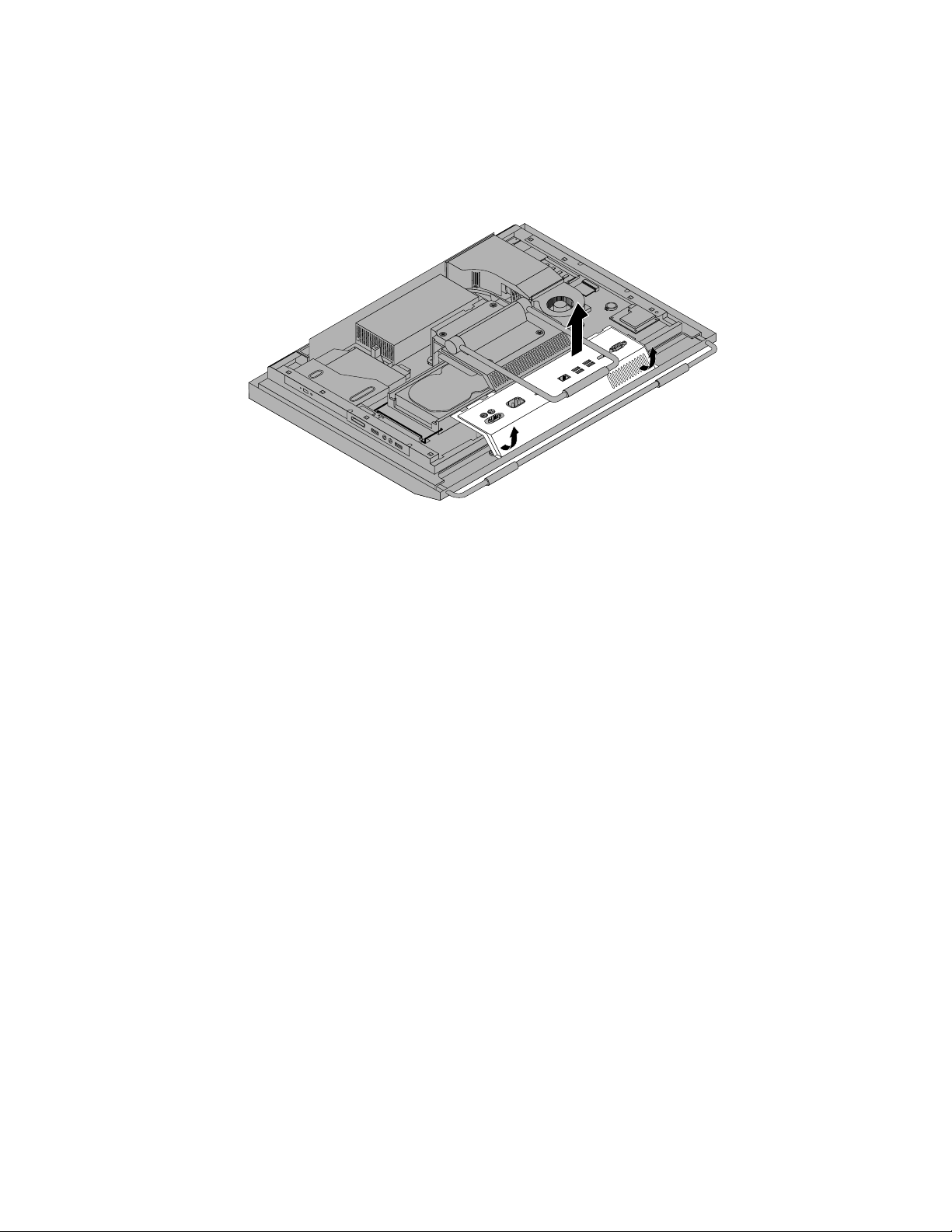
6.RemovetheVESAframecover.See“RemovingorreinstallingtheVESAframecover”onpage20.
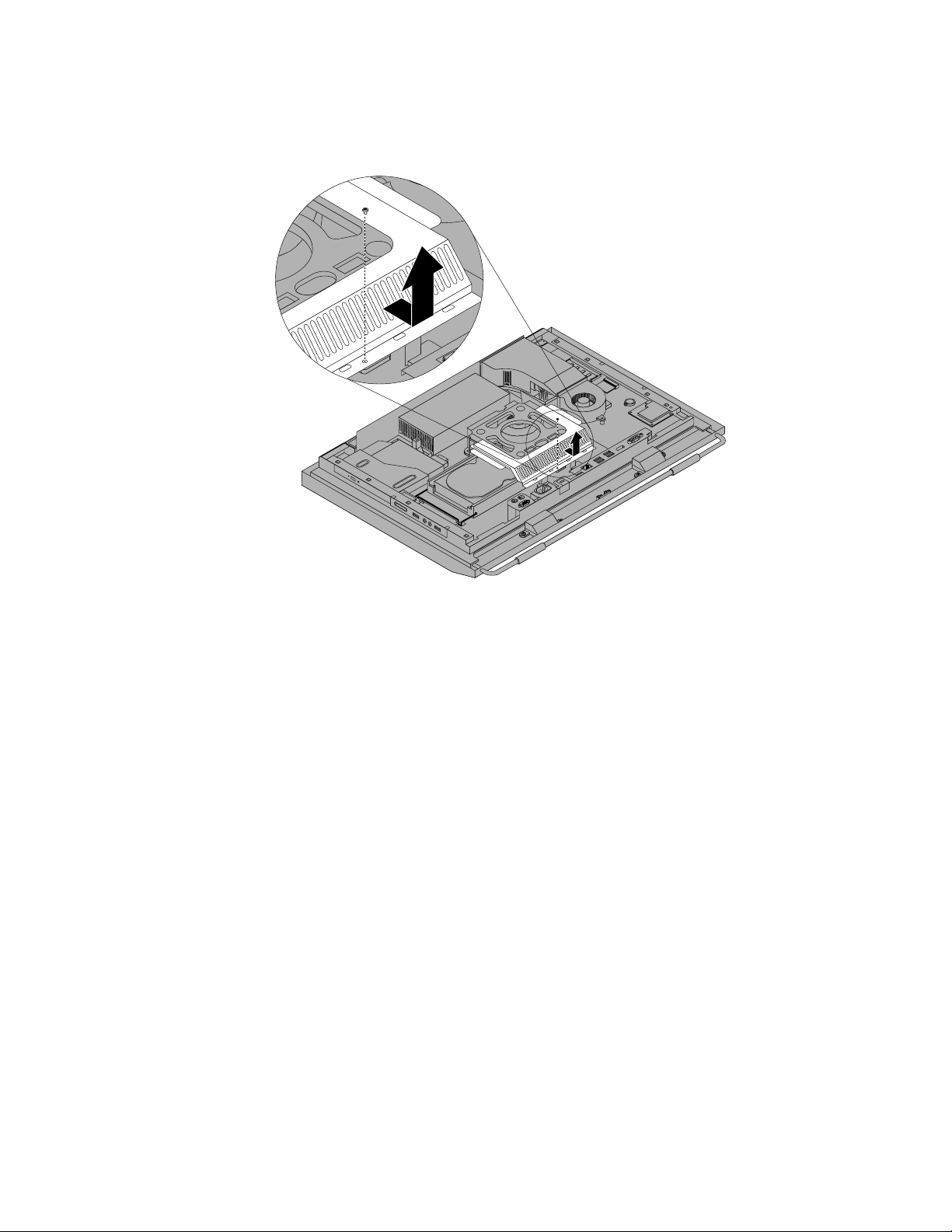
7.Notetheroutingofthemicroprocessorfanassemblycableandthendisconnectthemicroprocessorfan
assemblycablefromthesystemboard.
8.Removethethreescrews1thatsecurethemicroprocessorfanassemblyandthenliftthe
microprocessorfanassemblyoffthesystemboard.
Figure33.Removingthemicroprocessorfanassembly
9.Positionthenewmicroprocessorfanassemblyonthesystemboardandalignthethreescrewholesin
thenewmicroprocessorfanassemblywiththoseinthesystemboard.
10.Installthethreescrewstosecurethemicroprocessorfanassemblytothesystemboard.
11.Connectthemicroprocessorfanassemblycabletothesystemboard.See“Systemboardpartand
connectorlocations”onpage12.
12.ReinstalltheVESAframecoverandtherearI/Oassemblycover.
Whattodonext:
•T oworkwithanotherpieceofhardware,gototheappropriatesection.
•T ocompletetheinstallationorreplacement,goto“Completingthepartsreplacement”onpage52.
Chapter2.Installingorreplacinghardware43
Page 52

Replacingthecardreader
Attention:
Donotopenyourcomputerorattemptanyrepairbeforereadingandunderstandingthe“Importantsafetyinformation”
intheThinkCentreSafetyandWarrantyGuidethatcamewithyourcomputer.ToobtainacopyoftheThinkCentre
SafetyandWarrantyGuide,goto:
http://www.lenovo.com/support
Thissectionprovidesinstructionsonhowtoreplacethecardreader.
Note:Thecardreaderisavailableonlyinsomemodels.
Toreplacethecardreader,dothefollowing:
1.Removeallmediafromthedrivesandturnoffallattacheddevicesandthecomputer.Then,disconnect
allpowercordsfromelectricaloutletsanddisconnectallcablesthatareconnectedtothecomputer.
2.Placeasoft,cleantowelorclothonthedeskorsurface.Holdthesidesofyourcomputerandgentlylay
itdownsothatthescreenisagainstthesurfaceandthecoverisfacingup.
3.Removethecomputercover.See“Removingthecomputercover”onpage15.
4.Locatethecardreaderinthecomputer.See“Componentlocations”onpage11.
5.DisconnecttheUSBcablefromthecardreader.
6.Removethetwoscrewsthatsecurethecardreaderandthenliftthecardreaderoutofthecomputer.
Figure34.Removingthecardreader
7.Alignthescrewholesinthenewcardreaderwiththoseinthecomputerandtheninstallthetwoscrews
tosecurethecardreader.
8.ConnecttheUSBcabletothenewcardreader.
Whattodonext:
•T oworkwithanotherpieceofhardware,gototheappropriatesection.
•T ocompletetheinstallationorreplacement,goto“Completingthepartsreplacement”onpage52.
44ThinkCentreUserGuide
Page 53

ReplacingtherearI/Oassembly
Attention:
Donotopenyourcomputerorattemptanyrepairbeforereadingandunderstandingthe“Importantsafetyinformation”
intheThinkCentreSafetyandWarrantyGuidethatcamewithyourcomputer.ToobtainacopyoftheThinkCentre
SafetyandWarrantyGuide,goto:
http://www.lenovo.com/support
ThissectionprovidesinstructionsonhowtoreplacetherearI/Oassembly.
ToreplacetherearI/Oassembly,dothefollowing:
1.Removeallmediafromthedrivesandturnoffallattacheddevicesandthecomputer.Then,disconnect
allpowercordsfromelectricaloutletsanddisconnectallcablesthatareconnectedtothecomputer.
2.Placeasoft,cleantowelorclothonthedeskorsurface.Holdthesidesofyourcomputerandgentlylay
itdownsothatthescreenisagainstthesurfaceandthecoverisfacingup.
3.Removethecomputercover.See“Removingthecomputercover”onpage15.
4.RemovetherearI/Oassemblycover.See“RemovingorreinstallingtherearI/Oassemblycover”
onpage19.
5.LocatetherearI/Oassembly.See“Componentlocations”onpage11.
6.Removethefourscrews1thatsecuretherearI/OassemblyandthenremovetherearI/Oassembly
fromthecomputer.
Figure35.RemovingtherearI/Oassembly
7.T oinstallthenewrearI/Oassemblyintothecomputer,connectthenewrearI/Oassemblytotherear
I/Oassemblyconnectoronthesystemboard,andthenalignthefourscrewholeswiththoseinthe
computermainbracket.See“Systemboardpartandconnectorlocations”onpage12.
Chapter2.Installingorreplacinghardware45
Page 54

8.InstallthefourscrewstosecuretherearI/Oassemblytothecomputermainbracket.
9.ReinstalltherearI/Oassemblycover.See“RemovingorreinstallingtherearI/Oassemblycover”
onpage19.
Whattodonext:
•T oworkwithanotherpieceofhardware,gototheappropriatesection.
•T ocompletetheinstallationorreplacement,goto“Completingthepartsreplacement”onpage52
ReplacingtherightI/Oassembly
Attention:
Donotopenyourcomputerorattemptanyrepairbeforereadingandunderstandingthe“Importantsafetyinformation”
intheThinkCentreSafetyandWarrantyGuidethatcamewithyourcomputer.ToobtainacopyoftheThinkCentre
SafetyandWarrantyGuide,goto:
http://www.lenovo.com/support
ThissectionprovidesinstructionsonhowtoreplacetherightI/Oassembly.
ToreplacetherightI/Oassembly,dothefollowing:
1.Removeallmediafromthedrivesandturnoffallattacheddevicesandthecomputer.Then,disconnect
allpowercordsfromelectricaloutletsanddisconnectallcablesthatareconnectedtothecomputer.
2.Placeasoft,cleantowelorclothonthedeskorsurface.Holdthesidesofyourcomputerandgentlylay
itdownsothatthescreenisagainstthesurfaceandthecoverisfacingup.
3.Removethecomputercover.See“Removingthecomputercover”onpage15.
4.LocatetherightI/Oassembly.See“Componentlocations”onpage11.
5.DisconnecttherightI/OassemblycableandtheintrusionswitchcablefromtherightI/Oassembly.
6.Removethethreescrews1thatsecuretherightI/OassemblyandthenremovetherightI/Oassembly
fromthecomputer.
.
Figure36.RemovingtherightI/Oassembly
46ThinkCentreUserGuide
Page 55

7.T oinstallthenewrightI/Oassemblyintothecomputer,positionthenewrightI/Oassemblyintoplace
andthenalignthescrewholeswiththecorrespondingholesinthecomputermainbracket.
8.InstallthethreescrewstosecuretherightI/Oassemblytothecomputermainbracket.
9.ConnecttherightI/OassemblycableandtheintrusionswitchcabletothenewrightI/Oassembly.
Whattodonext:
•T oworkwithanotherpieceofhardware,gototheappropriatesection.
•T ocompletetheinstallationorreplacement,goto“Completingthepartsreplacement”onpage52.
Replacingthepowersupply
Attention:
Donotopenyourcomputerorattemptanyrepairbeforereadingandunderstandingthe“Importantsafetyinformation”
intheThinkCentreSafetyandWarrantyGuidethatcamewithyourcomputer.ToobtainacopyoftheThinkCentre
SafetyandWarrantyGuide,goto:
http://www.lenovo.com/support
Thissectionprovidesinstructionsonhowtoreplacethepowersupply.
CAUTION:
Neverremovethecoveronapowersupplyoranypartthathasthefollowinglabelattached.
Hazardousvoltage,current,andenergylevelsarepresentinsideanycomponentthathasthislabel
attached.Therearenoserviceablepartsinsidethesecomponents.Ifyoususpectaproblemwith
oneoftheseparts,contactaservicetechnician.
Toreplacethepowersupply,dothefollowing:
1.Removeallmediafromthedrivesandturnoffallattacheddevicesandthecomputer.Then,disconnect
allpowercordsfromelectricaloutletsanddisconnectallcablesthatareconnectedtothecomputer.
2.Placeasoft,cleantowelorclothonthedeskorsurface.Holdthesidesofyourcomputerandgentlylay
itdownsothatthescreenisagainstthesurfaceandthecoverisfacingup.
3.Removethecomputercover.See“Removingthecomputercover”onpage15.
4.Disconnectthepowersupplycablefromthesystemboard.See“Systemboardpartandconnector
locations”onpage12.
5.Removetheharddiskdrive.See“Replacingtheharddiskdrive”onpage25.
6.RemovetherearI/Oassemblycover.See“RemovingorreinstallingtherearI/Oassemblycover”
onpage19.
Chapter2.Installingorreplacinghardware47
Page 56

7.Removethefourscrews1thatsecurethepowersupplyandthenremovethetwoscrews2that
securethepowercordconnectorbracket.Notetheroutingofthepowercordconnectorcable3.Lift
thepowersupplyuptoremoveitfromthecomputermainbracket.
Figure37.Removingthepowersupply
8.Removethetwoscrews4(asshowninRemovingthepowersupplyFigure37onpage48)thatsecure
thepowercordconnectorandthenremovethepowercordconnectorfromthepowercordconnector
bracket.
9.Installthetwoscrewstosecurethenewpowercordconnectortothepowercordconnectorbracket.
10.Positionthenewpowersupplyinthecomputerandalignthefourscrewholesinthenewpowersupply
withthoseinthecomputermainbracket.Installthefourscrewstosecurethenewpowersupply.
11.Routethenewpowercordconnectorcableandthenpositionthepowercordconnectorbracketonthe
bottomofthecomputermainbracket.
12.Alignthetwoscrewholesinthepowercordconnectorbracketwiththoseinthecomputermainbracket
andinstallthetwoscrewstosecurethepowercordconnectorbracket.
13.Connectthenewpowersupplycabletothepowersupplyconnectoronthesystemboard.See“System
boardpartandconnectorlocations”onpage12.
14.Reinstalltheharddiskdrive.See“Replacingtheharddiskdrive”onpage25.
15.ReinstalltherearI/Oassemblycover.See“RemovingorreinstallingtherearI/Oassemblycover”
onpage19.
Whattodonext:
•T oworkwithanotherpieceofhardware,gototheappropriatesection.
•T ocompletetheinstallationorreplacement,goto“Completingthepartsreplacement”onpage52.
48ThinkCentreUserGuide
Page 57

Replacingthekeyboard
Attention:
Donotopenyourcomputerorattemptanyrepairbeforereadingandunderstandingthe“Importantsafetyinformation”
intheThinkCentreSafetyandWarrantyGuidethatcamewithyourcomputer.ToobtainacopyoftheThinkCentre
SafetyandWarrantyGuide,goto:
http://www.lenovo.com/support
Thissectionprovidesinstructionsonhowtoreplacethekeyboard.
ReplacingthePS/2orUSBkeyboard
ToreplacethePS/2orUSBkeyboard,dothefollowing:
1.Removeanymediafromthedrives.Then,turnoffallattacheddevicesandthecomputer.
2.Disconnectallpowercordsfromelectricaloutlets.
3.Locatethekeyboardconnector.
Note:YourkeyboardmightbeconnectedtoaPS/2keyboardconnector1oraUSBconnector2.
Figure38.Keyboardconnectors
4.Disconnectthefailingkeyboardfromthecomputer.
5.Connectanewkeyboardtotheappropriateconnectoronthecomputer.
6.Reconnectallpowercordstoelectricaloutlets.
Replacingthewirelesskeyboard
Toreplacethewirelesskeyboard,dothefollowing:
1.T akeawayyourfailingwirelesskeyboard.
2.Removethenewwirelesskeyboardfromthepackage.
Chapter2.Installingorreplacinghardware49
Page 58

3.Correctlyinstallthebatteriesforthenewwirelesskeyboardbyreferringtothefollowingillustrations:
4.RemovetheUSBdonglefromthewirelessmousecompartmentandconnectittoanavailableUSB
connectorsonthecomputer.See“Replacingthewirelessmouse”onpage51
.
Replacingthemouse
Attention:
Donotopenyourcomputerorattemptanyrepairbeforereadingandunderstandingthe“Importantsafetyinformation”
intheThinkCentreSafetyandWarrantyGuidethatcamewithyourcomputer.ToobtainacopyoftheThinkCentre
SafetyandWarrantyGuide,goto:
http://www.lenovo.com/support
Thissectionprovidesinstructionsonhowtoreplacethemouse.
ReplacingthePS/2orUSBmouse
ToreplacethePS/2orUSBmouse,dothefollowing:
1.Removeanymediafromthedrives.Then,turnoffallattacheddevicesandthecomputer.
50ThinkCentreUserGuide
Page 59

2.Disconnectallpowercordsfromelectricaloutlets.
3.Locatethemouseconnector.
Note:YourmousemightbeconnectedtoaPS/2mouseconnector
Figure39.Mouseconnectors
1oraUSBconnector2.
4.Disconnectthefailingmousecablefromthecomputer.
5.Connectanewmousecabletotheappropriateconnectoronthecomputer.
6.Reconnectallpowercordstoelectricaloutlets.
Replacingthewirelessmouse
Toreplacethewirelessmouse,dothefollowing:
1.DisconnecttheUSBdonglefromyourcomputer.Then,takeawayyourfailingwirelessmouse.
2.Removethenewwirelessmousefromthepackage.
3.RemovetheUSBdonglefromthecompartmentofthenewwirelessmouseandcorrectlyinstallthe
batteriesforthemouse.Then,connecttheUSBdongletoanavailableUSBconnectoronyourcomputer.
Chapter2.Installingorreplacinghardware51
Page 60

Notes:Tosaveyourbatteryenergy,dothefollowingwhenyouarenotusingthewirelesskeyboardand
mouse:
1.Switchoffthepowerbuttononthebottomofthewirelessmouse.
2.DisconnecttheUSBdonglefromyourcomputerandstoreitinthewirelessmousecompartment.
Completingthepartsreplacement
Aftercompletingtheinstallationorreplacementforallparts,youneedtoreinstallthecomputercover
andreconnectcables.
Toreinstallthecomputercoverandreconnectcables,dothefollowing:
1.Makesurethatallcomponentshavebeenreassembledcorrectlyandthatnotoolsorloosescrews
areleftinsideyourcomputer.See“Componentlocations”onpage11forthelocationsofvarious
componentsinyourcomputer.
2.Makesurethatthecablesareroutedcorrectlybeforereinstallingthecomputercover.Keepcablesclear
ofthehingesandsidesofthecomputerchassistoavoidinterferencewithreinstallingthecomputer
cover.
52ThinkCentreUserGuide
Page 61

3.Lowerandpositionthecomputercoverintoplaceandthenslidethecomputercovertowardthebottom
ofthecomputeruntilthecoverissecuredintoplace.
Figure40.Installingthecomputercover
4.Lockthecomputercoverifyouhaveanintegratedcablelock.See“Integratedcablelock”onpage53
and“Rearview”onpage9.
5.Reconnecttheexternalcablesandpowercordtothecomputer.See“Rearview”onpage9.
6.Dependingonthepartsyouinstalledorreplaced,youmightneedtoconrmtheupdatedinformationin
theSetupUtilityprogram.RefertoChapter4“UsingtheSetupUtilityprogram”onpage63.
Note:Inmostareasoftheworld,LenovorequiresthereturnofthedefectiveCustomerReplaceableUnit
(CRU).InformationaboutthiswillcomewiththeCRUorwillcomeafewdaysaftertheCRUarrives.
Obtainingdevicedrivers
Youcanobtaindevicedriversforoperatingsystemsthatarenotpreinstalledat
http://www.lenovo.com/support.Installationinstructionsareprovidedinreadmeleswiththedevice
driverles.
Basicsecurityfeatures
Thereareseveralsecurityoptionsavailabletohelpyoupreventhardwaretheftandunauthorizedaccessto
yourcomputer.Inadditiontophysicallocks,youcanalsopreventunauthorizeduseofyourcomputerbya
softwarelockthatlocksthekeyboarduntilacorrectpasswordistypedin.
Integratedcablelock
Note:Makesurethatanysecuritycablesyouinstalleddonotinterferewithothercomputercables.
Chapter2.Installingorreplacinghardware53
Page 62

Anintegratedcablelock,sometimesreferredtoastheKensingtonlock,canbeusedtosecureyour
computertoadesk,atable,orothernon-permanentxture.Theintegratedcablelockattachestothe
integratedcablelockslotintherearofyourcomputerandisoperatedwithakey.See“Rearview”onpage9
forthelocationoftheintegratedcablelockslot.Thisisthesametypeoflockusedwithmanynotebook
computers.YoucanorderanintegratedcablelockfromLenovobysearchingforKensingtonat:
http://www.lenovo.com/support
Figure41.Integratedcablelock
Passwordprotection
Todeterunauthorizeduseofyourcomputer,youcanusetheSetupUtilityprogramtosetapassword.When
youturnonyourcomputer,youarepromptedtotypethepassword.Thecomputercannotbeuseduntil
avalidpasswordistypedin.RefertoChapter4“UsingtheSetupUtilityprogram”onpage63
information.
formore
Erasinglostorforgottenpasswords(clearingCMOS)
Thissectionprovidesinstructionsonhowtoeraselostorforgottenpasswords,suchasauserpassword.
Toerasealostorforgottenpassword,dothefollowing:
1.Removeallmediafromthedrivesandturnoffallattacheddevicesandthecomputer.Then,disconnect
allpowercordsfromelectricaloutletsanddisconnectallcablesthatareconnectedtothecomputer.
2.Removethecomputercover.See“Removingthecomputercover”onpage15.
3.LocatetheClearCMOS/Recoveryjumperonthesystemboard.See“Systemboardpartandconnector
locations”onpage12.
4.Movethejumperfromthestandardposition(pin1andpin2)tothemaintenanceposition(pin2and
pin3).
54ThinkCentreUserGuide
Page 63

5.Closethecomputercoverandconnectthepowercord.See“Completingthepartsreplacement”
onpage52.
6.T urnonthecomputerandleaveitonforapproximately10seconds.Then,turnoffthecomputerby
holdingthepowerswitchforapproximatelyveseconds.
7.Repeatstep1throughstep3.
8.MovetheClearCMOS/Recoveryjumperbacktothestandardposition(pin1andpin2).
9.Closethecomputercoverandconnectthepowercord.See“Completingthepartsreplacement”
onpage52.
Chapter2.Installingorreplacinghardware55
Page 64

56ThinkCentreUserGuide
Page 65

Chapter3.Recoveryinformation
ThischapterprovidesinformationabouttherecoverysolutionsprovidedbyLenovo.
Thischaptercontainsthefollowingtopics:
•“Creatingandusingrecoverymedia”onpage57
•“Performingbackupandrecoveryoperations”onpage58
•“UsingtheRescueandRecoveryworkspace”onpage59
•“Creatingandusingarescuemedium”onpage60
•“Installingorreinstallingdevicedrivers”onpage61
•“Solvingrecoveryproblems”onpage62
Notes:
1.Thereareavarietyofmethodstochoosefromwhenconsideringhowtorecoverintheeventofa
software-orhardware-relatedproblem.Somemethodsvarydependingonthetypeofyouroperating
system.
2.Theproductontherecoverymediamaybeusedonlyforthefollowingpurposes:
•Restoretheproductpreinstalledonyourcomputer
•Reinstalltheproduct
•ModifytheproductusingtheAdditionalFiles
Creatingandusingrecoverymedia
Youcanuserecoverymediatorestoretheharddiskdrivetothefactorydefaultsettings.Recoverymedia
areusefulifyoutransferthecomputertoanotherarea,sellthecomputer,recyclethecomputer,orputthe
computerinanoperationalstateafterallothermethodsofrecoveryhavefailed.Asaprecautionarymeasure,
itisimportanttocreaterecoverymediaasearlyaspossible.
Note:Therecoveryoperationsyoucanperformusingrecoverymediavarydependingontheoperating
systemfromwhichtherecoverymediawerecreated.Therecoverymediamightcontainabootmedium
andadatamedium.YourMicrosoftWindowslicensepermitsyoutocreateonlyonedatamedium,soitis
importantthatyoustoretherecoverymediainasafeplaceafteryouhavemadethem.
Creatingrecoverymedia
Thissectionprovidesinstructionsonhowtocreaterecoverymediaondifferentoperatingsystems.
Note:OntheWindows7operatingsystem,youcancreaterecoverymediausingdiscsorexternalUSB
storagedevices.OntheWindowsVistaoperatingsystems,youcancreaterecoverymediausingonlydiscs,
sothisoperationisalsocalled“creatingProductRecoverydiscs. ”
•T ocreaterecoverymediaontheWindows7operatingsystem,clickStart➙AllPrograms➙Lenovo
ThinkVantageT ools➙FactoryRecoveryDisks.Then,followtheinstructionsonthescreen.
•T ocreateProductRecoverydiscsontheWindowsVistaoperatingsystem,clickStart➙AllPrograms➙
ThinkVantage➙CreateProductRecoveryMedia.Then,followtheinstructionsonthescreen.
Usingrecoverymedia
ThissectionprovidesinstructionsonhowtouserecoverymediaontheWindows7operatingsystem.
©CopyrightLenovo,2011
57
Page 66

OntheWindows7operatingsystemandtheWindowsVistaoperatingsystem,youcanuserecoverymedia
torestorethecomputertothefactorydefaultsettingsonly.Y oucanuserecoverymediatoputthecomputer
inanoperationalstateafterallothermethodsofrecoveryhavefailed.
Attention:Whenyouuserecoverymediatorestorethecomputertothefactorydefaultsettings,alltheles
currentlyontheharddiskdrivewillbedeletedandreplacedbythefactorydefaultsettings.
TouserecoverymediaontheWindows7operatingsystemortheWindowsVistaoperatingsystem,
dothefollowing:
1.Dependingonthetypeofyourrecoverymedia,connectthebootmedium(memorykeyorotherUSB
storagedevice)tothecomputer,orinsertthebootdiscintotheopticaldrive.
2.RepeatedlypressandreleasetheF12keywhenturningonthecomputer.WhentheStartupDevice
Menuopens,releasetheF12key.
3.SelectthedesiredstartupdeviceandpressEnter.Therestoreprocessbegins.
4.Followtheinstructionsonthescreentocompletetheoperation.
Notes:
1.Afterrestoringyourcomputertothefactorydefaultsettings,youmighthavetoreinstalldevicedrivers
forsomedevices.See“Installingorreinstallingdevicedrivers”onpage61.
2.SomecomputerscomewithMicrosoftOfceorMicrosoftWorkspreinstalled.Ifyouneedtorecover
orreinstallyourMicrosoftOfceorMicrosoftWorksapplications,youmustusetheMicrosoftOfce
CDorMicrosoftWorksCD.ThesediscsareprovidedonlywithcomputerspreinstalledwithMicrosoft
OfceorMicrosoftWorks.
Performingbackupandrecoveryoperations
TheRescueandRecoveryprogramenablesyoutobackupallyourharddiskdrivecontentsincludingthe
operatingsystem,datales,softwareprograms,andpersonalsettings.Y oucandesignatewherethe
RescueandRecoveryprogramstoresthebackup:
•Inaprotectedareaofyourharddiskdrive
•Onthesecondaryharddiskdriveifasecondaryharddiskdriveisinstalledinyourcomputer
•OnanattachedexternalUSBharddiskdrive
•Onanetworkdrive
•Onrecordablediscs(arecordableopticaldriveisrequiredforthisoption)
Afteryouhavebackedupthecontentsontheharddiskdrive,youcanrestorethecompletecontentsofthe
harddiskdrive,restoreonlytheselectedles,orrestoreonlytheWindowsoperatingsystemandapplications.
Performingabackupoperation
ThissectionprovidesinstructionsonhowtoperformabackupoperationusingtheRescueandRecovery
programondifferentoperatingsystems.
•T operformabackupoperationusingtheRescueandRecoveryprogramontheWindows7operating
system,dothefollowing:
1.FromtheWindowsdesktop,clickStart➙AllPrograms➙LenovoThinkVantageTools➙
EnhancedBackupandRestore.TheRescueandRecoveryprogramopens.
2.IntheRescueandRecoverymainwindow,clicktheLaunchadvancedRescueandRecoveryarrow.
3.ClickBackupyourharddriveandselectbackupoperationoptions.Then,followtheinstructionson
thescreentocompletethebackupoperation.
58ThinkCentreUserGuide
Page 67

•T operformabackupoperationusingtheRescueandRecoveryprogramontheWindowsVistaoperating
system,dothefollowing:
1.FromtheWindowsdesktop,clickStart➙AllPrograms➙ThinkVantage➙RescueandRecovery.
TheRescueandRecoveryprogramopens.
2.IntheRescueandRecoverymainwindow,clickLaunchadvancedRescueandRecovery➙Back
upyourharddrive,andselectbackupoperationoptions.
3.Followtheinstructionsonthescreentocompletethebackupoperation.
Performingarecoveryoperation
ThissectionprovidesinstructionsonhowtoperformarecoveryoperationusingtheRescueandRecovery
programondifferentoperatingsystems.
•T operformarecoveryoperationusingtheRescueandRecoveryprogramontheWindows7operating
system,dothefollowing:
1.FromtheWindowsdesktop,clickStart➙AllPrograms➙LenovoThinkVantageTools➙
EnhancedBackupandRestore.TheRescueandRecoveryprogramopens.
2.IntheRescueandRecoverymainwindow,clicktheLaunchadvancedRescueandRecoveryarrow.
3.ClicktheRestoreyoursystemfromabackupicon.
4.Followtheinstructionsonthescreentocompletetherecoveryoperation.
•T operformarecoveryoperationusingtheRescueandRecoveryprogramontheWindowsVistaoperating
system,dothefollowing:
1.FromtheWindowsdesktop,clickStart➙AllPrograms➙ThinkVantage➙RescueandRecovery.
TheRescueandRecoveryprogramopens.
2.IntheRescueandRecoverymainwindow,clickLaunchadvancedRescueandRecovery.
3.ClicktheRestoreyoursystemfromabackupicon.
4.Followtheinstructionsonthescreentocompletetherecoveryoperation.
FormoreinformationaboutperformingarecoveryoperationfromtheRescueandRecoveryworkspace,see
“UsingtheRescueandRecoveryworkspace”onpage59.
UsingtheRescueandRecoveryworkspace
TheRescueandRecoveryworkspaceresidesinaprotected,hiddenareaofyourharddiskdrivethat
operatesindependentlyfromtheWindowsoperatingsystem.Thisenablesyoutoperformrecovery
operationsevenifyoucannotstarttheWindowsoperatingsystem.Y oucanperformthefollowingrecovery
operationsfromtheRescueandRecoveryworkspace:
•RescuelesfromyourharddiskdriveorfromabackupTheRescueandRecoveryworkspaceenables
youtolocatelesonyourharddiskdriveandtransferthemtoanetworkdriveorotherrecordablemedia,
suchasaUSBdeviceoradisc.Thissolutionisavailableevenifyoudidnotbackupyourlesorif
changesweremadetothelessinceyourlastbackupoperation.Y oucanalsorescueindividuallesfrom
aRescueandRecoverybackuplocatedonyourlocalharddiskdrive,aUSBdevice,oranetworkdrive.
•RestoreyourharddiskdrivefromaRescueandRecoverybackupIfyouhavebackedupyourharddisk
driveusingtheRescueandRecoveryprogram,youcanrestoretheharddiskdrivefromaRescueand
Recoverybackup,evenifyoucannotstarttheWindowsoperatingsystem.
•RestoreyourharddiskdrivetothefactorydefaultsettingsTheRescueandRecoveryworkspaceenables
youtorestorethecompletecontentsofyourharddiskdrivetothefactorydefaultsettings.Ifyouhave
multiplepartitionsonyourharddiskdrive,youhavetheoptiontorestorethefactorydefaultsettingstothe
C:partitionandleavetheotherpartitionsintact.BecausetheRescueandRecoveryworkspaceoperates
Chapter3.Recoveryinformation59
Page 68

independentlyfromtheWindowsoperatingsystem,youcanrestorethefactorydefaultsettingsevenif
youcannotstarttheWindowsoperatingsystem.
Attention:IfyourestoretheharddiskdrivefromaRescueandRecoverybackuporrestoretheharddisk
drivetothefactorydefaultsettings,alllesontheprimaryharddiskdrivepartition(usuallydriveC:)willbe
deletedintherecoveryprocess.Ifpossible,makecopiesofimportantles.Ifyouareunabletostartthe
Windowsoperatingsystem,youcanusetherescuelesfeatureoftheRescueandRecoveryworkspaceto
copylesfromyourharddiskdrivetoothermedia.
TostarttheRescueandRecoveryworkspace,dothefollowing:
1.Makesurethecomputeristurnedoff.
2.RepeatedlypressandreleasetheF11keywhenturningonthecomputer.Whenyouhearbeepsor
seealogoscreen,releasetheF11key.
3.IfyouhavesetaRescueandRecoverypassword,typeyourpasswordwhenprompted.TheRescue
andRecoveryworkspaceopensafterashortdelay.
Note:IftheRescueandRecoveryworkspacefailstoopen,see“Solvingrecoveryproblems”onpage62.
4.Dooneofthefollowing:
•T orescuelesfromyourharddiskdriveorfromabackup,clickRescuelesandfollowthe
instructionsonthescreen.
•T orestoreyourharddiskdrivefromaRescueandRecoverybackuportorestoreyourharddiskdrive
tothefactorydefaultsettings,clickRestoreyoursystemandfollowtheinstructionsonthescreen.
FormoreinformationaboutthefeaturesoftheRescueandRecoveryworkspace,clickHelp.
Notes:
1.Afterrestoringyourharddiskdrivetothefactorydefaultsettings,youmighthavetoreinstalldevice
driversforsomedevices.See“Installingorreinstallingdevicedrivers”onpage61.
2.SomecomputerscomewithMicrosoftOfceorMicrosoftWorkspreinstalled.Ifyouneedtorecover
orreinstallyourMicrosoftOfceorMicrosoftWorksapplications,youmustusetheMicrosoftOfce
CDorMicrosoftWorksCD.ThesediscsareprovidedonlywithcomputerspreinstalledwithMicrosoft
OfceorMicrosoftWorks.
Creatingandusingarescuemedium
Witharescuemedium,suchasadiscoraUSBharddiskdrive,youcanrecoverthecomputerfromfailures
thatpreventyoufromgainingaccesstotheRescueandRecoveryworkspaceonyourharddiskdrive.
Notes:
1.Therecoveryoperationsyoucanperformusingarescuemediumvarydependingontheoperating
system.
2.Therescuedisccanbestartedinalltypesofopticaldrives.
3.Y oucanalsorunthePC-DoctorforRescueandRecoverydiagnosticprogram,afterusingarescue
mediumtorecoverthecomputerfromfailuresandgainingaccesstotheRescueandRecovery
workspace.
Creatingarescuemedium
Thissectionprovidesinstructionsonhowtocreatearescuemediumondifferentoperatingsystems.
•T ocreatearescuemediumontheWindows7operatingsystem,dothefollowing:
60ThinkCentreUserGuide
Page 69

1.FromtheWindowsdesktop,clickStart➙AllPrograms➙LenovoThinkVantageTools➙
EnhancedBackupandRestore.TheRescueandRecoveryprogramopens.
2.IntheRescueandRecoverymainwindow,clicktheLaunchadvancedRescueandRecoveryarrow.
3.ClicktheCreateRescueMediaicon.TheCreateRescueandRecoveryMediawindowopens.
4.IntheRescueMediaarea,selectthetypeoftherescuemediumyouwanttocreate.Youcancreate
arescuemediumusingadisc,aUSBharddiskdrive,orasecondaryinternalharddiskdrive.
5.ClickOKandfollowtheinstructionsonthescreentocreatearescuemedium.
•T ocreatearescuemediumontheWindowsVistaoperatingsystem,dothefollowing:
1.FromtheWindowsdesktop,clickStart➙AllPrograms➙ThinkVantage➙CreateRecovery
Media.TheCreateRescueandRecoveryMediawindowopens.
2.IntheRescueMediaarea,selectthetypeoftherescuemediumyouwanttocreate.Youcancreate
arescuemediumusingadisc,aUSBharddiskdrive,orasecondaryinternalharddiskdrive.
3.ClickOKandfollowtheinstructionsonthescreentocreatearescuemedium.
Usingarescuemedium
Thissectionprovidesinstructionsonhowtousetherescuemediumyouhavecreated.
•Ifyouhavecreatedarescuemediumusingadisc,dothefollowingtousetherescuemedium:
1.T urnoffyourcomputer.
2.RepeatedlypressandreleasetheF12keywhenturningonthecomputer.WhentheStartupDevice
Menuopens,releasetheF12key.
3.OntheStartupDeviceMenu,selectthedesiredopticaldriveastherstbootdevice.Then,insert
therescuediscintotheopticaldriveandpressEnter.Therescuemediumstarts.
•IfyouhavecreatedarescuemediumusingaUSBharddiskdrive,dothefollowingtousetherescue
medium:
1.AttachtheUSBharddiskdrivetooneoftheUSBconnectorsonyourcomputer.
2.RepeatedlypressandreleasetheF12keywhenturningonthecomputer.WhentheStartupDevice
Menuopens,releasetheF12key.
3.OntheStartupDeviceMenu,selecttheUSBharddiskdriveastherstbootdeviceandpressEnter.
Therescuemediumstarts.
•Ifyouhavecreatedarescuemediumusingthesecondaryinternalharddiskdrive,setthesecondary
internalharddiskdriveastherstbootdeviceinthestartupdevicesequencetostarttherescuemedium.
See“Selectingastartupdevice”onpage65.
Note:Thesecondaryinternalharddiskdriveisonlyavailableinsomecomputermodels.
Whentherescuemediumstarts,theRescueandRecoveryworkspaceopens.Thehelpinformationfor
eachfeatureisavailablefromtheRescueandRecoveryworkspace.Followtheinstructionstocomplete
therecoveryprocess.
Installingorreinstallingdevicedrivers
Beforeinstallingorreinstallingdevicedrivers,makesurethatyouhaveapreinstalledoperatingsystemand
thedocumentationandsoftwaremediaforthedevice.
Devicedriversforfactory-installeddevicesarelocatedonthecomputerharddiskdrive(usuallydriveC:)
intheSWTOOLS\DRIVERSsubdirectory.Thelatestdevicedriversforfactory-installeddevicesarealso
availableathttp://www.lenovo.com/support.Otherdevicedriversareonthesoftwaremediathatcome
withindividualdevices.
Chapter3.Recoveryinformation61
Page 70

Toinstallorreinstallthedevicedriverforafactory-installeddevice,dothefollowing:
1.T urnonthecomputer.
2.UseWindowsExplorerorMyComputertodisplaythedirectorystructureofyourharddiskdrive.
3.GototheC:\SWTOOLSdirectory.
4.OpentheDRIVERSfolder.WithintheDRIVERSfolder,thereareseveralsubfoldersnamedforvarious
devicesinstalledinyourcomputer,suchasAUDIOorVIDEO.
5.Opentheappropriatedevicesubfolder.
6.Dooneofthefollowing:
•Inthedevicesubfolder,lookforaSETUP .exele.Double-clicktheleandfollowtheinstructionson
thescreentocompletetheinstallation.
•Inthedevicesubfolder,lookforaREADME.txtleoralewiththe.txtextension.Thislemightbe
namedaftertheoperatingsystem,suchasWIN98.txt.TheTXTlecontainsinformationabouthowto
installthedevicedriver.Followtheinstructionstocompletetheinstallation.
•Ifthedevicesubfoldercontainsalewiththe.infextensionandyouwanttoinstallthedevice
driverusingtheINFle,refertoyourWindowsHelpandSupportinformationsystemfordetailed
informationabouthowtoinstallthedevicedriver.
Solvingrecoveryproblems
IfyouareunabletoaccesstheRescueandRecoveryworkspaceortheWindowsenvironment,doone
ofthefollowing:
•UsearescuemediumtostarttheRescueandRecoveryworkspace.See“Creatingandusingarescue
medium”onpage60.
•Userecoverymediaifallothermethodsofrecoveryhavefailedandyouneedtorestoretheharddisk
drivetothefactorydefaultsettings.See“Creatingandusingrecoverymedia”onpage57.
Note:IfyouareunabletoaccesstheRescueandRecoveryworkspaceortheWindowsenvironmentfrom
arescuemediumorrecoverymedia,youmightnothavetherescuedevice(aninternalharddiskdrive,a
disc,aUSBharddiskdrive,orotherexternaldevices)setastherstbootdeviceinthestartupdevice
sequence.Y oumustrstmakesurethatyourrescuedeviceissetastherstbootdeviceinthestartup
devicesequenceintheSetupUtilityprogram.See“Selectingastartupdevice”onpage65fordetailed
informationabouttemporarilyorpermanentlychangingthestartupdevicesequence.Formoreinformation
abouttheSetupUtilityprogram,seeChapter4“UsingtheSetupUtilityprogram”onpage63
Itisimportanttocreatearescuemediumandasetofrecoverymediaasearlyaspossibleandstorethem
inasafeplaceforfutureuse.
.
62ThinkCentreUserGuide
Page 71

Chapter4.UsingtheSetupUtilityprogram
YoucanusetheSetupUtilityprogramtoviewandchangethecongurationsettingsofyourcomputer,
regardlessofwhichoperatingsystemyouareusing.However,theoperatingsystemsettingsmightoverride
anysimilarsettingsintheSetupUtilityprogram.
ThischapterprovidesinformationaboutthefollowingtopicstohelpyouusetheSetupUtilityprogram:
•“StartingtheSetupUtilityprogram”onpage63
•“Viewingorchangingsettings”onpage63
•“Usingpasswords”onpage63
•“Selectingastartupdevice”onpage65
•“ExitingtheSetupUtilityprogram”onpage66
StartingtheSetupUtilityprogram
ThissectionprovidesinstructionsonhowtostarttheSetupUtilityprogram.
TostarttheSetupUtilityprogram,dothefollowing:
1.Makesureyourcomputeristurnedoff.
2.RepeatedlypressandreleasetheF1keywhenturningonthecomputer.Whenyouseealogoscreen,
releasetheF1key.TheSetupUtilityprogramopens.
Note:Ifapasswordhasbeenset,theSetupUtilityprogrammenuwillnotbedisplayeduntilyoutype
thecorrectpassword.Formoreinformation,see“Usingpasswords”onpage63.
Viewingorchangingsettings
TheSetupUtilityprogrammenulistsvariousitemsaboutthesystemcongurationsettings.Toviewor
changethesettings,starttheSetupUtilityprogram.See“StartingtheSetupUtilityprogram”onpage
63.Then,followtheinstructionsonthescreen.
WhenworkingwiththeSetupUtilityprogram,youmustusethekeyboard.Thekeysusedtoperformvarious
tasksaredisplayedatthebottomofeachscreen.
Usingpasswords
ByusingtheSetupUtilityprogram,youcansetapasswordtopreventunauthorizedaccesstoyour
computeranddata.Thefollowingoptionsareavailabletohelpyousetanadministratorpassword,a
power-onpassword,oraharddiskdrivepassword:
•SetAdministratorPassword
•SetPower-OnPassword
•HardDiskPassword
Youdonothavetosetapasswordtouseyourcomputer.However,usingapasswordimprovescomputing
security.Ifyoudecidetosetapassword,readthefollowingsections.
©CopyrightLenovo,2011
63
Page 72

Passwordconsiderations
Apasswordcanbeanycombinationofupto64(1to64)alphabeticandnumericcharacters.Forsecurity
reasons,itisrecommendedtouseastrongpasswordthatcannotbeeasilycompromised.Tosetastrong
password,usethefollowingguidelines:
Note:TheSetupUtilityprogrampasswordsarenotcasesensitive.
•Haveatleasteightcharactersinlength
•Containatleastonealphabeticcharacterandonenumericcharacter
•Notbeyournameoryourusername
•Notbeacommonwordoracommonname
•Besignicantlydifferentfromyourpreviouspasswords
Administratorpassword
TheSetAdministratorPasswordoptionenablesyoutosetanadministratorpassword,whichdeters
unauthorizedusersfromchangingcongurationsettings.Ifyouareresponsibleformaintainingthesettings
ofseveralcomputers,youmightwanttosetanadministratorpassword.Formoreinformationonhowtoset
apassword,see“Setting,changing,ordeletingapassword”onpage64
Afteryouhavesetanadministratorpassword,apasswordpromptisdisplayedeachtimeyoutrytoaccess
theSetupUtilityprogram.Y oucannotaccesstheSetupUtilityprogramuntilavalidpasswordistypedin.
Ifyouhavesetbothauserpasswordandanadministratorpassword,youcantypeeitherpasswordtouse
yourcomputer.However,tochangeanycongurationsettings,youmustuseyouradministratorpassword.
.
Power-onpassword
Afteryouhavesetapower-onpasswordusingtheSetPower-OnPasswordoption,apasswordpromptis
displayedeachtimeyouturnonthecomputer.Y oucannotusethecomputeruntilavalidpasswordistyped
in.Formoreinformationabouthowtosetapassword,see“Setting,changing,ordeletingapassword”
onpage64
.
Harddiskdrivepassword
TheHardDiskPasswordoptionenablesyoutosetaharddiskdrivepassword,whichpreventsunauthorized
accesstothedataontheharddiskdrive.Whenaharddiskdrivepasswordisset,youarepromptedtotype
avalidpasswordeachtimeyoutrytoaccesstheharddiskdrive.Formoreinformationonhowtosetahard
diskdrivepassword,see“Setting,changing,ordeletingapassword”onpage64.
Setting,changing,ordeletingapassword
Thissectionprovidesinstructionsonhowtoset,change,ordeleteapassword.
Toset,change,ordeleteapassword,dothefollowing:
1.StarttheSetupUtilityprogram.See“StartingtheSetupUtilityprogram”onpage63.
2.FromtheSetupUtilityprogrammainmenu,selectSecurity.
3.Dependingonthepasswordtype,selectSetAdministratorPassword,SetPower-OnPassword,or
HardDiskPassword.
4.Followtheinstructionsonthescreentoset,change,ordeleteapassword.
Note:Apasswordcanbeanycombinationofupto64(1to64)alphabeticandnumericcharacters.
Formoreinformation,see“Passwordconsiderations”onpage64.
64ThinkCentreUserGuide
Page 73

Enablingordisablingadevice
Thissectionprovidesinstructionsonhowtoenableordisableuseraccesstoadevice.
USBSupportUsethisoptiontoenableordisableaUSBconnector.WhenaUSBconnectoris
disabled,thedeviceconnectedtotheUSBconnectorcannotbeused.
SATAControllerWhenthisoptionissettoDisabled,thedeviceconnectedtotheSA TAconnector(such
astheharddiskdriveortheopticaldrive)isdisabledandcannotbeaccessed.
Toenableordisableadevice,dothefollowing:
1.StarttheSetupUtilityprogram.See“StartingtheSetupUtilityprogram”onpage63.
2.Dependingonthedeviceyouwanttoenableordisable,dooneofthefollowing:
•FromtheSetupUtilityprogrammainmenu,selectDevices➙USBSetupandfollowtheinstructions
onthescreentoenableordisabletheUSBconnector(s)ofyourchoice.
•FromtheSetupUtilityprogrammainmenu,selectDevices➙A TADriveSetup➙SAT AControllerto
enableordisablethedeviceconnectedtothecorrespondingSAT Aconnectoronthesystemboard.
3.SelectthedesiredsettingsandpressEnter.
4.PressEsctoreturntotheSetupUtilityprogrammainmenu.YoumighthavetopressEscseveraltimes.
5.PressF10tosavethenewsettingsandexittheSetupUtilityprogram.
Notes:
a.Ifyoudonotwanttosavethenewsettings,selectExit➙DiscardChangesandExit.
b.Ifyouwanttoreturntothedefaultsettings,pressF9orselectExit➙LoadOptimalDefaults.
Selectingastartupdevice
Ifyourcomputerdoesnotstartupfromadevice(suchasaharddiskdriveorthediscinanopticaldrive)as
expected,dooneofthefollowingtoselectthedesiredstartupdevice.
Selectingatemporarystartupdevice
Thissectionprovidesinstructionsonhowtoselectatemporarystartupdevice.Y oucanusetheinstructions
inthissectiontostartupfromanystartupdevice.
Note:Notalldiscsandharddiskdrivesarebootable.
Toselectatemporarystartupdevice,dothefollowing:
1.T urnoffyourcomputer.
2.RepeatedlypressandreleasetheF12keywhenturningonthecomputer.WhentheStartupDevice
Menuopens,releasetheF12key.
3.SelectthedesiredstartupdeviceontheStartupDeviceMenuandpressEntertobegin.
Note:SelectingastartupdeviceontheStartupDeviceMenudoesnotpermanentlychangethestartup
devicesequence.
Viewingorchangingthestartupdevicesequence
Thissectionprovidesinstructionsonhowtovieworpermanentlychangetheconguredstartupdevice
sequence.
Chapter4.UsingtheSetupUtilityprogram65
Page 74

Tovieworpermanentlychangetheconguredstartupdevicesequence,dothefollowing:
1.StarttheSetupUtilityprogram.See“StartingtheSetupUtilityprogram”onpage63.
2.SelectStartup➙PrimaryBootSequence.Readtheinformationdisplayedontherightsideofthe
screen.
3.Selecttherstbootdevice,secondbootdevice,andsoon.
4.PressEsctoreturntotheStartupmenu.Then,selectthedevicesfortheAutomaticBootSequence
andErrorBootSequence.
5.PressEsctoreturntotheSetupUtilityprogrammainmenu.YoumighthavetopressEscseveraltimes.
6.PressF10tosavethenewsettingsandexittheSetupUtilityprogram.
Notes:
a.Ifyoudonotwanttosavethenewsettings,selectExit➙DiscardChangesandExit.
b.Ifyouwanttoreturntothedefaultsettings,pressF9orselectExit➙LoadOptimalDefaults.
ExitingtheSetupUtilityprogram
Afteryounishviewingorchangingsettings,pressEsctoreturntotheSetupUtilityprogrammainmenu.
YoumighthavetopressEscseveraltimes.Then,youcandooneofthefollowing:
•IfyouwanttosavethenewsettingsandexittheSetupUtilityprogram,pressF10orselectExit➙Save
ChangesandExit.Otherwise,yourchangeswillnotbesaved.
•Ifyoudonotwanttosavethenewsettings,selectExit➙DiscardChangesandExit.
•Ifyouwanttoreturntothedefaultsettings,pressF9orselectExit➙LoadOptimalDefaults.
66ThinkCentreUserGuide
Page 75

Chapter5.Updatingsystemprograms
ThischapterprovidesinformationaboutupdatingthePOSTandBIOS,andhowtorecoverfromaPOST
andBIOSupdatefailure.
Thischaptercontainsthefollowingtopics:
•“Usingsystemprograms”onpage67
•“Updating(ashing)theBIOSfromadisc”onpage67
•“Updating(ashing)theBIOSfromyouroperatingsystem”onpage68
•“RecoveringfromaPOST/BIOSupdatefailure”onpage68
Usingsystemprograms
Systemprogramsarethebasiclayerofsoftwarebuiltintoyourcomputer.Systemprogramsincludethe
POST,theBIOS,andtheSetupUtilityprogram.ThePOSTisasetoftestsandproceduresthatare
performedeachtimeyouturnonyourcomputer.TheBIOSisalayerofsoftwarethattranslatesinstructions
fromotherlayersofsoftwareintoelectricalsignalsthatthecomputerhardwarecanexecute.Youcanuse
theSetupUtilityprogramtovieworchangethecongurationsettingsofyourcomputer.SeeChapter4
“UsingtheSetupUtilityprogram”onpage63fordetailedinformation.
Yourcomputersystemboardhasamodulecalledelectricallyerasableprogrammableread-onlymemory
(EEPROM,alsoreferredtoasashmemory).Y oucaneasilyupdatethePOST,theBIOS,andtheSetup
Utilityprogrambystartingyourcomputerwithasystem-program-updatediscorrunningaspecialupdate
programfromyouroperatingsystem.
LenovomightmakechangesandenhancementstothePOSTandBIOS.Whenupdatesarereleased,they
areavailableasdownloadablelesontheLenovoWebsiteathttp://www.lenovo.com.Instructionsforusing
thePOSTandBIOSupdatesareavailableinaTXTlethatisincludedwiththeupdateles.Formost
models,youcandownloadeitheranupdateprogramtocreateasystem-program-updatediscoranupdate
programthatcanberunfromtheoperatingsystem.
Updating(ashing)theBIOSfromadisc
Thissectionprovidesinstructionsonhowtoupdate(ash)theBIOSfromadisc.
Note:Y oucandownloadaself-startingbootablediscimage(knownasanISOimage)withthesystem
programupdatestocreateasystem-program-updatedisc.Goto:
http://www.lenovo.com/support
Toupdate(ash)theBIOSfromadisc,dothefollowing:
1.T urnoffyourcomputer.
2.RepeatedlypressandreleasetheF12keywhenturningonthecomputer.WhentheStartupDevice
Menuopens,releasetheF12key.
3.OntheStartupDeviceMenu,selectthedesiredopticaldriveastherstbootdevice.Then,insertthe
discintotheopticaldriveandpressEnter.Theupdatebegins.
4.Whenpromptedtochangetheserialnumber,itissuggestedthatyoupressN.However,ifyoudowant
tochangetheserialnumber,pressY,thentypeintheserialnumberandpressEnter.
©CopyrightLenovo,2011
67
Page 76

5.Whenpromptedtochangethemachinetypeandmodel,itissuggestedthatyoupressN.However,if
youdowanttochangethemachinetypeandmodel,pressY,thentypeinthemachinetypeand
modelandpressEnter.
6.Followtheinstructionsonthescreentocompletetheupdate.Aftertheupdateiscompleted,removethe
discfromtheopticaldrive.
Updating(ashing)theBIOSfromyouroperatingsystem
Note:BecauseLenovomakesconstantimprovementstoitsWebsites,theWebpagecontentsaresubject
tochangewithoutnotice,includingthecontentsreferencedinthefollowingprocedure.
Toupdate(ash)theBIOSfromyouroperatingsystem,dothefollowing:
1.Gotohttp://www.lenovo.com/support.
2.Dothefollowingtolocatethedownloadablelesforyourmachinetype:
a.IntheEnteraproductnumbereld,typeyourmachinetypeandclickGo.
b.ClickDownloadsanddrivers.
c.SelectBIOSfromtheReneresultsdrop-downlistboxtoeasilylocatealltheBIOSrelatedlinks.
d.ClicktheBIOSupdatelink.
3.ClicktheTXTlethatcontainstheinstructionsforupdating(ashing)theBIOSfromyouroperating
system.
4.Printtheseinstructions.Thisisveryimportantbecausetheseinstructionswillnotbedisplayedon
thescreenafterthedownloadbegins.
5.Followtheprintedinstructionstodownload,extract,andinstalltheupdate.
RecoveringfromaPOST/BIOSupdatefailure
IfthepowertoyourcomputerisinterruptedwhilethePOST/BIOSisbeingupdated(ashupdate),your
computermightnotrestartcorrectly.Ifthishappens,performthefollowingprocedurecommonlycalled
Boot-blockRecovery.
1.Removeallmediafromthedrivesandturnoffallattacheddevicesandthecomputer.Then,disconnect
allpowercordsfromelectricaloutletsanddisconnectallcablesthatareconnectedtothecomputer.
2.Removethecomputercover.See“Removingthecomputercover”onpage15.
3.LocatetheClearCMOS/Recoveryjumperonthesystemboard.See“Systemboardpartandconnector
locations”onpage12.
4.Movethejumperfromthestandardposition(pin1andpin2)tothemaintenanceposition(pin2and
pin3).
5.Installthecomputercoverandreconnectallcablesandpowercordsthatweredisconnected.See
“Completingthepartsreplacement”onpage52.
6.RepeatedlypressandreleasetheF12keywhenturningonthecomputer.WhentheStartupDevice
Menuopens,releasetheF12key.
7.InsertthePOST/BIOSupdate(ash)discintotheopticaldrive.Then,selecttheopticaldriveasthe
startupdeviceandpressEnter.Therecoverysessionbegins.
Note:Therecoverysessionwilltaketwotothreeminutes.Duringthistimeyouwillhearaseries
ofbeeps.
8.Aftertherecoverysessioniscompleted,theseriesofbeepswillend,andthesystemwillautomatically
turnoff.Removethediscfromtheopticaldrivebeforethesystemcompletelyturnsoff.
9.Repeatsteps1through3.
10.MovetheClearCMOS/Recoveryjumperbacktothestandardposition(pin1andpin2).
68ThinkCentreUserGuide
Page 77

11.Installthecomputercoverandreconnectallcablesandpowercordsthatweredisconnected.See
“Completingthepartsreplacement”onpage52.
12.T urnonthecomputertorestarttheoperatingsystem.
Chapter5.Updatingsystemprograms69
Page 78

70ThinkCentreUserGuide
Page 79

Chapter6.Troubleshootinganddiagnosticprograms
Thischapterprovidesinformationaboutsomebasictroubleshootinganddiagnosticprograms.Ifyour
computerproblemisnotdescribedinthischapter,seeChapter7“Gettinginformation,help,andservice”on
page75foradditionaltroubleshootingresources.
Thischaptercontainsthefollowingtopics:
•“Basictroubleshooting”onpage71
•“Diagnosticprograms”onpage72
•“Cleaninganopticalmouse”onpage74
Basictroubleshooting
Thefollowingtableprovidessomebasicinformationtohelpyoutroubleshootyourcomputerproblems.
Note:Ifyoucannotsolvetheproblemafterdoingthebasictroubleshooting,havethecomputerserviced.
RefertotheThinkCentreSafetyandWarrantyGuidethatcamewithyourcomputerforthesafetyand
warrantyinformationandthelistofserviceandsupporttelephonenumbers.Youcanalsogetthelatest
serviceandsupporttelephonenumbersfromtheLenovoSupportWebsiteat:
http://www.lenovo.com/support
SymptomAction
Thecomputerdoesnotstart
whenyoupressthepower
switch.
Themonitorscreenisblank.
TheUSBkeyboardormouse
doesnotwork.
Verifythat:
•Thepowercordiscorrectlyconnectedtotherearofthecomputerandtoa
workingelectricaloutlet.
•Thepowerindicatoronthefrontofthecomputerison.
•Thecomputervoltagematchesthevoltageavailableattheelectricaloutletfor
yourcountryorregion.
Verifythat:
•Thepowercordiscorrectlyconnectedtotherearofthecomputerandtoa
workingelectricaloutlet.
•Thecomputervoltagematchesthevoltageavailableattheelectricaloutletfor
yourcountryorregion.
•Thebrightnessandcontrastcontrolsaresetcorrectly.
Verifythat:
•Thecomputeristurnedon.
•TheUSBkeyboardormouseiscorrectlyconnectedtooneoftheUSB
connectorsonthecomputer.
•FortheUSBkeyboard,nokeysarestuck.
•TheUSBmouseisclean.Referto“Cleaninganopticalmouse”onpage74.
©CopyrightLenovo,2011
71
Page 80

SymptomAction
Thewirelesskeyboardormouse
doesnotwork.
Theoperatingsystemdoesnot
start.
Thecomputerbeepsmultiple
timesbeforetheoperating
systemstarts.
Verifythat:
•Thecomputeristurnedon.
•Thebatteryorbatteriesinstalledinthewirelesskeyboardormouseareingood
condition.
•Thewirelesscongurationsareallsetcorrectly.Youmightneedtoreferto
thedocumentationthatcomewiththewirelesskeyboardormouse,orrefer
toyourWindowsHelpandSupportinformationsystemforwirelessrelated
instructions.Ifyourwirelessmousehasadongle,makesurethedongleis
correctlyconnectedtooneoftheUSBconnectorsonthecomputer.
•Forthewirelesskeyboard,nokeysarestuck.
•Thewirelessmouseisclean.
Verifythatyoulistthedevicewheretheoperatingsystemresidesinthestartup
devicesequence.Usually,theoperatingsystemisontheharddiskdrive.Formore
information,see“Selectingastartupdevice”onpage65
Verifythatnokeysarestuck.
.
Diagnosticprograms
Diagnosticprogramsareusedtotesthardwarecomponentsofyourcomputer.Diagnosticprogramscan
alsoreportoperating-system-controlledsettingsthatinterferewiththecorrectoperationofyoursystem.The
followingprogramsarepreinstalledonyourcomputertohelpyoudiagnosecomputerproblems:
•LenovoThinkVantageT oolbox(usedwhenyouarerunningtheWindowsoperatingsystem)
•PC-DoctorforRescueandRecovery(usedwhenyoucannotstarttheWindowsoperatingsystem)
Notes:
1.Y oucanalsodownloadthePC-DoctorforDOSdiagnosticprogramfromhttp://www.lenovo.com/support.
See“PC-DoctorforDOS”onpage73fordetailedinformation.
2.Ifyouareunabletoisolateandrepairtheproblemyourselfafterrunningtheprograms,saveandprint
theloglescreatedbytheprograms.YouwillneedthelogleswhenyouspeaktoaLenovotechnical
supportrepresentative.
LenovoThinkVantageT oolbox
TheLenovoThinkVantageToolboxprogramhelpsyoumaintainyourcomputer,improvecomputingsecurity,
diagnosecomputerproblems,getfamiliarwiththeinnovativetechnologiesprovidedbyLenovo,andget
moreinformationaboutyourcomputer.YoucanusethediagnosticsfeatureoftheLenovoThinkVantage
Toolboxprogramtotestdevices,diagnosecomputerproblems,createbootablediagnosticmedia,update
systemdrivers,andviewsysteminformation.
•T oruntheLenovoThinkVantageT oolboxprogramontheWindows7operatingsystem,clickStart➙All
Programs➙LenovoThinkVantageTools➙SystemHealthandDiagnostics.Followtheinstructions
onthescreen.
•T oruntheLenovoThinkVantageT oolboxprogramontheWindowsVistaoperatingsystem,clickStart➙
AllPrograms➙ThinkVantage➙LenovoThinkVantageT oolbox.Followtheinstructionsonthescreen.
ForadditionalinformationaboutrunningtheLenovoThinkVantageToolboxprogram,refertotheLenovo
ThinkVantageToolboxhelpsystem.
72ThinkCentreUserGuide
Page 81

PC-DoctorforRescueandRecovery
ThePC-DoctorforRescueandRecoverydiagnosticprogramispartoftheRescueandRecoveryworkspace
onyourLenovocomputer.UsethePC-DoctorforRescueandRecoveryprogramifyouareunableto
starttheWindowsoperatingsystem.
TorunthePC-DoctorforRescueandRecoveryprogramfromtheRescueandRecoveryworkspace,do
thefollowing:
1.T urnoffthecomputer.
2.RepeatedlypressandreleasetheF11keywhenturningonthecomputer.Whenyouhearbeepsorsee
alogoscreen,releasetheF11key.TheRescueandRecoveryworkspaceopensafterashortdelay.
3.FromtheRescueandRecoveryworkspace,selectLaunchadvancedRescueandRecovery➙
Diagnosehardware.ThePC-DoctorforRescueandRecoveryprogramopens.
4.Selectthedesireddiagnostictest.Then,followtheinstructionsonthescreen.
ForadditionalinformationaboutrunningthePC-DoctorforRescueandRecoveryprogram,refertothe
PC-DoctorforRescueandRecoveryhelpsystem.
Note:IfyouencounterfailuresthatpreventyoufromgainingaccesstotheRescueandRecovery
workspace,youcanrunthePC-DoctorforRescueandRecoveryprogramafterusingarescuemedium
torecoverthecomputerfromfailuresandgainingaccesstotheRescueandRecoveryworkspace.See
“Creatingandusingarescuemedium”onpage60.
PC-DoctorforDOS
YoucanalsodownloadthelatestversionofthePC-DoctorforDOSdiagnosticprogramfrom
http://www.lenovo.com/support.ThePC-DoctorforDOSdiagnosticprogramrunsindependentlyofthe
Windowsoperatingsystem.UsethePC-DoctorforDOSdiagnosticprogramifyouareunabletostartthe
Windowsoperatingsystem.YoucanrunthePC-DoctorforDOSdiagnosticprogramfromadiagnostic
discthatyoucreated.
Creatingadiagnosticdisc
Thissectionprovidesinstructionsonhowtocreateadiagnosticdisc.
Tocreateadiagnosticdisc,dothefollowing:
1.Downloadaself-startingbootablediscimage(knownasanISOimage)ofthediagnosticprogramfrom:
http://www.lenovo.com/support
2.UseanyCD/DVDburningsoftwaretocreateadiagnosticdiscwiththeISOimage.
Runningthediagnosticprogramfromthediagnosticdisc
Thissectionprovidesinstructionsonhowtorunthediagnosticprogramfromthediagnosticdiscthat
youcreated.
Torunthediagnosticprogramfromthediagnosticdiscthatyoucreated,dothefollowing:
1.Makesurethatyourcomputeristurnedoff.
2.RepeatedlypressandreleasetheF12keywhenturningonthecomputer.WhentheStartupDevice
Menuopens,releasetheF12key.
3.Insertthediagnosticdiscintotheopticaldrive.
4.SelecttheopticaldrivewiththediagnosticdiscasthestartupdeviceandpressEnter.Thediagnostic
programopens.
5.Followtheinstructionsonthescreentorunthedesireddiagnostictest.Foradditionalhelp,press
theF1key.
Chapter6.Troubleshootinganddiagnosticprograms73
Page 82

6.Removethediagnosticdiscfromtheopticaldriveaftercompletingthediagnostictest.
Cleaninganopticalmouse
Thissectionprovidesinstructionsonhowtocleananopticalmouse.
AnopticalmouseusesaLEDandanopticalsensortonavigatethepointer.Ifthepointeronthescreendoes
notmovesmoothlywiththeopticalmouse,youmightneedtocleanthemouse.
Tocleananopticalmouse,dothefollowing:
1.T urnoffyourcomputer.
2.Disconnectthemousecablefromthecomputer.
3.T urnthemouseupsidedowntoviewthelens.
a.Ifthereisasmudgeonthelens,gentlycleantheareawithaplaincotton-tippedswab.
b.Ifthereisdebrisinthelens,gentlyblowthedebrisawayfromthearea.
4.Checkthesurfaceonwhichyouareusingthemouse.Ifyouhaveaveryintricatepictureorpattern
beneaththemouse,itmaybedifcultforthedigitalsignalprocessor(DSP)todeterminechanges
inthemouseposition.
5.Reconnectthemousecabletothecomputer.
6.T urnyourcomputerbackon.
74ThinkCentreUserGuide
Page 83

Chapter7.Gettinginformation,help,andservice
Thischapterprovidesinformationabouthelp,service,andtechnicalassistanceforLenovoproducts.
Thischaptercontainsthefollowingtopics:
•“Informationresources”onpage75
•“Helpandservice”onpage77
Informationresources
Youcanusetheinformationinthissectiontoaccessusefulresourcesrelatingtoyourcomputingneeds.
OnlineBooksfolder
TheOnlineBooksfolderpreinstalledonyourcomputercontainstheThinkCentreUserGuide,whichprovides
informationaboutyourcomputertohelpyousetup,use,andmaintainyourcomputer.Itrequiresno
Internetaccesstoviewthepublication.
Toviewthepublication,clickStart➙AllPrograms➙OnlineBooks➙OnlineBooks,thendouble-click
thepublicationforyourcomputer.ThepublicationisalsoavailableontheLenovoSupportWebsiteat:
http://www.lenovo.com/support
Notes:
1.ThepublicationisinPDFversion.T oviewthepublication,youneedtohavetheAdobeReaderprogram
preinstalledonyourcomputer.IftheAdobeReaderprogramhasnotbeeninstalledonyourcomputer,a
messagewillbedisplayedwhenyouattempttoviewthePDFleandyouwillbeguidedthrough
theAdobeReaderinstallation.
2.ThepublicationisavailableinotherlanguagesontheLenovoSupportWebsiteat:
http://www.lenovo.com/support
3.IfyouwanttoinstalladifferentlanguageversionoftheAdobeReaderprogramratherthantheversion
preinstalledonyourcomputer,downloadthedesiredlanguageversionfromtheAdobeWebsiteat:
http://www.adobe.com
LenovoThinkVantageT ools
TheLenovoThinkVantageToolsprogramhelpsyouworkmoreeasilyandsecurelybyprovidingeasyaccess
tovarioustools,suchas:
•LenovoThinkVantageToolbox
•PowerManager
•ProductRecovery
•RescueandRecovery
•SystemUpdate
ToaccesstheLenovoThinkVantageToolsprogram,clickStart➙AllPrograms➙LenovoThinkVantage
Tools.
ThinkVantageProductivityCenter
Note:TheThinkVantageProductivityCenterprogramisonlyavailableoncomputerspreinstalledwith
theWindowsVistaoperatingsystemfromLenovo.
75
Page 84

TheThinkVantageProductivityCenterprogramcontainsinformationsourcesandtoolsdesignedtomake
computingeasyandsecure.Itprovideseasyaccesstovarioustechnologies,suchas:
•PowerManager
•ProductRecovery
•RescueandRecovery
•SystemUpdate
ToaccesstheThinkVantageProductivityCenterprogram,clickStart➙AllPrograms➙ThinkVantage
➙ProductivityCenter.
LenovoWelcome
TheLenovoWelcomeprogramintroducessomeinnovativebuilt-infeaturesofLenovotoyouandguidesyou
throughsomeimportantsetuptaskstohelpyoumakethemostofyourcomputer.
AccessHelp
TheAccessHelpinformationsystemprovidesinformationaboutgettingstarted,doingbasictasks,
customizingsettingsforyourpersonalpreference,protectingdata,expandingandupgrading,and
troubleshooting.
•T oopentheAccessHelpinformationsystemontheWindows7operatingsystem,clickStart➙Help
andSupport➙LenovoAccessHelp.
•T oopentheAccessHelpinformationsystemontheWindowsVistaoperatingsystem,clickStart➙
AllPrograms➙ThinkVantage➙AccessHelp.
AfteryouhaveopenedtheAccessHelpinformationsystem,usetheleftpaneltomakeaselectionfromthe
ContentstabortheIndextab,orusetheSearchtabtondaparticularwordorphrase.
Safetyandwarranty
TheThinkCentreSafetyandWarrantyGuidethatcamewithyourcomputercontainsinformationabout
safety,warranty,serviceandsupportphonenumbers,CRUs,andothernoticesandinformationresources.
Beforeusingtheinformationinthismanualandtheproductitsupports,besuretoreadandunderstandthe
ThinkCentreSafetyandWarrantyGuideandAppendixA“Notices”onpage79
.
LenovoWebsite(http://www.lenovo.com)
TheLenovoWebsiteprovidesup-to-dateinformationandservicestohelpyoubuy,upgrade,andmaintain
yourcomputer.Y oucanalsodothefollowing:
•Shopfordesktopandnotebookcomputers,monitors,projectors,upgradesandaccessoriesforyour
computer,andspecialoffers.
•Purchaseadditionalservices,suchassupportforhardware,operatingsystems,softwareprograms,
networksetupandconguration,andcustominstallations.
•Purchaseupgradesandextendedhardwarerepairservices.
•Downloadthelatestdevicedriversandsoftwareupdatesforyourcomputermodel.
•Accesstheonlinemanualsforyourproducts.
•AccesstheLenovoLimitedWarranty.
•Accesstroubleshootingandsupportinformationforyourcomputermodelandothersupportedproducts.
•Findtheserviceandsupportphonenumbersforyourcountryorregion.
76ThinkCentreUserGuide
Page 85

Chapter7.Gettinginformation,help,andservice
Thischapterprovidesinformationabouthelp,service,andtechnicalassistanceforLenovoproducts.
Thischaptercontainsthefollowingtopics:
•“Informationresources”onpage75
•“Helpandservice”onpage77
Informationresources
Youcanusetheinformationinthissectiontoaccessusefulresourcesrelatingtoyourcomputingneeds.
OnlineBooksfolder
TheOnlineBooksfolderpreinstalledonyourcomputercontainstheThinkCentreUserGuide,whichprovides
informationaboutyourcomputertohelpyousetup,use,andmaintainyourcomputer.Itrequiresno
Internetaccesstoviewthepublication.
Toviewthepublication,clickStart➙AllPrograms➙OnlineBooks➙OnlineBooks,thendouble-click
thepublicationforyourcomputer.ThepublicationisalsoavailableontheLenovoSupportWebsiteat:
http://www.lenovo.com/support
Notes:
1.ThepublicationisinPDFversion.T oviewthepublication,youneedtohavetheAdobeReaderprogram
preinstalledonyourcomputer.IftheAdobeReaderprogramhasnotbeeninstalledonyourcomputer,a
messagewillbedisplayedwhenyouattempttoviewthePDFleandyouwillbeguidedthrough
theAdobeReaderinstallation.
2.ThepublicationisavailableinotherlanguagesontheLenovoSupportWebsiteat:
http://www.lenovo.com/support
3.IfyouwanttoinstalladifferentlanguageversionoftheAdobeReaderprogramratherthantheversion
preinstalledonyourcomputer,downloadthedesiredlanguageversionfromtheAdobeWebsiteat:
http://www.adobe.com
LenovoThinkVantageT ools
TheLenovoThinkVantageToolsprogramhelpsyouworkmoreeasilyandsecurelybyprovidingeasyaccess
tovarioustools,suchas:
•LenovoThinkVantageToolbox
•PowerManager
•ProductRecovery
•RescueandRecovery
•SystemUpdate
ToaccesstheLenovoThinkVantageToolsprogram,clickStart➙AllPrograms➙LenovoThinkVantage
Tools.
ThinkVantageProductivityCenter
Note:TheThinkVantageProductivityCenterprogramisonlyavailableoncomputerspreinstalledwith
theWindowsVistaoperatingsystemfromLenovo.
©CopyrightLenovo,2011
75
Page 86

Ifpossible,beatyourcomputerwhenyoucall.Havethefollowinginformationavailable:
•Machinetypeandmodel
•Serialnumbersofyourhardwareproducts
•Descriptionoftheproblem
•Exactwordingofanyerrormessages
•Hardwareandsoftwarecongurationinformation
Usingotherservices
Ifyoutravelwithyourcomputerorrelocateittoacountrywhereyourdesktopornotebookcomputer
machinetypeissold,yourcomputermightbeeligibleforInternationalWarrantyService,whichautomatically
entitlesyoutoobtainwarrantyservicethroughoutthewarrantyperiod.Servicewillbeperformedbyservice
providersauthorizedtoperformwarrantyservice.
Servicemethodsandproceduresvarybycountry,andsomeservicesmightnotbeavailableinallcountries.
InternationalWarrantyServiceisdeliveredthroughthemethodofservice(suchasdepot,carry-in,or
on-siteservice)thatisprovidedintheservicingcountry.Servicecentersincertaincountriesmightnotbe
abletoserviceallmodelsofaparticularmachinetype.Insomecountries,feesandrestrictionsmight
applyatthetimeofservice.
TodeterminewhetheryourcomputeriseligibleforInternationalWarrantyServiceandtoviewalistofthe
countrieswhereserviceisavailable,gotohttp://www.lenovo.com/support,clickWarranty,andfollow
theinstructionsonthescreen.
FortechnicalassistancewiththeinstallationoforquestionsrelatedtoServicePacksforyour
preinstalledMicrosoftWindowsproduct,refertotheMicrosoftProductSupportServicesWebsiteat
http://support.microsoft.com/directoryoryoucancontacttheCustomerSupportCenter.Somefeesmight
apply.
Purchasingadditionalservices
Duringandafterthewarrantyperiod,youcanpurchaseadditionalservices,suchassupportforhardware,
operatingsystems,andapplicationprograms;networksetupandconguration;upgradedorextended
hardwarerepairservices;andcustominstallations.Serviceavailabilityandservicenamemightvaryby
countryorregion.Formoreinformationabouttheseservices,gototheLenovoWebsiteat:
http://www.lenovo.com
78ThinkCentreUserGuide
Page 87

AppendixA.Notices
Lenovomaynotoffertheproducts,services,orfeaturesdiscussedinthisdocumentinallcountries.Consult
yourlocalLenovorepresentativeforinformationontheproductsandservicescurrentlyavailableinyour
area.AnyreferencetoaLenovoproduct,program,orserviceisnotintendedtostateorimplythatonlythat
Lenovoproduct,program,orservicemaybeused.Anyfunctionallyequivalentproduct,program,orservice
thatdoesnotinfringeanyLenovointellectualpropertyrightmaybeusedinstead.However,itistheuser's
responsibilitytoevaluateandverifytheoperationofanyotherproduct,program,orservice.
Lenovomayhavepatentsorpendingpatentapplicationscoveringsubjectmatterdescribedinthis
document.Thefurnishingofthisdocumentdoesnotgiveyouanylicensetothesepatents.Youcansend
licenseinquiries,inwriting,to:
Lenovo(UnitedStates),Inc.
1009ThinkPlace-BuildingOne
Morrisville,NC27560
U.S.A.
Attention:LenovoDirectorofLicensing
LENOVOPROVIDESTHISPUBLICATION“ASIS”WITHOUTWARRANTYOFANYKIND,EITHEREXPRESS
ORIMPLIED,INCLUDING,BUTNOTLIMITEDTO,THEIMPLIEDWARRANTIESOFNON-INFRINGEMENT ,
MERCHANTABILITYORFITNESSFORAPARTICULARPURPOSE.Somejurisdictionsdonotallow
disclaimerofexpressorimpliedwarrantiesincertaintransactions,therefore,thisstatementmaynotapply
toyou.
Thisinformationcouldincludetechnicalinaccuraciesortypographicalerrors.Changesareperiodically
madetotheinformationherein;thesechangeswillbeincorporatedinneweditionsofthepublication.
Lenovomaymakeimprovementsand/orchangesintheproduct(s)and/ortheprogram(s)describedinthis
publicationatanytimewithoutnotice.
Theproductsdescribedinthisdocumentarenotintendedforuseinimplantationorotherlifesupport
applicationswheremalfunctionmayresultininjuryordeathtopersons.Theinformationcontainedinthis
documentdoesnotaffectorchangeLenovoproductspecicationsorwarranties.Nothinginthisdocument
shalloperateasanexpressorimpliedlicenseorindemnityundertheintellectualpropertyrightsofLenovo
orthirdparties.Allinformationcontainedinthisdocumentwasobtainedinspecicenvironmentsandis
presentedasanillustration.Theresultobtainedinotheroperatingenvironmentsmayvary.
Lenovomayuseordistributeanyoftheinformationyousupplyinanywayitbelievesappropriatewithout
incurringanyobligationtoyou.
Anyreferencesinthispublicationtonon-LenovoWebsitesareprovidedforconvenienceonlyanddonotin
anymannerserveasanendorsementofthoseWebsites.ThematerialsatthoseWebsitesarenotpartof
thematerialsforthisLenovoproduct,anduseofthoseWebsitesisatyourownrisk.
Anyperformancedatacontainedhereinwasdeterminedinacontrolledenvironment.Therefore,theresult
obtainedinotheroperatingenvironmentsmayvarysignicantly.Somemeasurementsmayhavebeen
madeondevelopment-levelsystemsandthereisnoguaranteethatthesemeasurementswillbethesame
ongenerallyavailablesystems.Furthermore,somemeasurementsmayhavebeenestimatedthrough
extrapolation.Actualresultsmayvary.Usersofthisdocumentshouldverifytheapplicabledatafortheir
specicenvironment.
©CopyrightLenovo,2011
79
Page 88

Televisionoutputnotice
Thefollowingnoticeappliestomodelsthathavethefactory-installedtelevision-outputfeature.
ThisproductincorporatescopyrightprotectiontechnologythatisprotectedbymethodclaimsofcertainU.S.
patentsandotherintellectualpropertyrightsownedbyMacrovisionCorporationandotherrightsowners.
UseofthiscopyrightprotectiontechnologymustbeauthorizedbyMacrovisionCorporation,andisintended
forhomeandotherlimitedviewingusesonlyunlessotherwiseauthorizedbyMacrovisionCorporation.
Reverseengineeringordisassemblyisprohibited.
EuropeanconformanceCEmark
Trademarks
ThefollowingtermsaretrademarksofLenovointheUnitedStates,othercountries,orboth:
Lenovo
TheLenovologo
PersonalSystem/2
PS/2
RescueandRecovery
ThinkCentre
ThinkVantage
Microsoft,Windows,andWindowsVistaaretrademarksoftheMicrosoftgroupofcompanies.
Intel,IntelCore,andPentiumaretrademarksofIntelCorporationintheUnitedStates,othercountries,or
both.
Othercompany,product,orservicenamesmaybetrademarksorservicemarksofothers.
80ThinkCentreUserGuide
Page 89

Index
A
arescuemedium,creatingandusing60
AccessHelp76
Administratorpassword64
ambientlightsensor,replacing37
antivirussoftware7
audiosubsystem1
B
backupandrecoveryoperations58
basictroubleshooting71
battery,replacing24
Bluetoothmodule,replacing35
boot-blockrecovery68
C
cardreader,replacing44
changing
startupdevicesequence65
cleaninganopticalmouse74
CMOS,clearing54
computercover
removing15
computercover,reinstalling52
computerliftstand17
removing17
connector10
considerations,password64
creating
andusingarescuemedium60
creatingandusing
recoverymedia57
CRU
completingtheinstallation52
CustomerSupportCenter77
D
Description10
devicedrivers53
installing61
reinstalling61
diagnosticprograms,troubleshooting71
diagnosticsprograms,using77
DisplayPortoutconnector10
documentation,using77
drivers,device53
Ethernetconnector10
exiting,SetupUtilityprogram66
expansion2
ExpressCard,replacing39
externaloptions,installing15
F
features1
ashingtheBIOS67
framestand16
removing16
G
getting
help75
information75
service75
H
harddiskdrive,replacing25
heatsink,replacing29
help
AccessHelp76
andservice77
getting75
I
importantsafetyinformationv
information
getting75
importantsafetyv
resources75
safety76
warranty76
Input/Output(I/O)features2
installing
devicedrivers61
installingoptions
memorymodule22
securityfeatures53
integratedcablelock,security53
integratedcamerawithmicrophone,replacing41
internaldrives1
internalspeakers,replacing40
E
environment,operating5
Ethernet2
©CopyrightLenovo,2011
K
keyboardconnector10
keyboard,replacing49
81
Page 90

L
LenovoThinkVantageToolbox72
LenovoWebsite76
LenovoWelcome6
M
media,creatingandusingrecoverymedia57
memorymodule
installing22
systemboard22
Microphoneconnector10
microprocessorfanassembly,replacing42
mouseconnector10
mouse,replacing50
multi-touchboard,replacing36
N
notice,televisionoutput80
notices79
O
OnlineBooksfolder75
operations,backupandrecovery58
opticaldrive,replacing28
opticalmouse
cleaning74
software57
recovery
boot-block68
operations,backupand58
problems,solving62
recoverymedia,creatingandusing57
reinstalling
devicedrivers61
removingcomputercover15
replacing
ambientlightsensor37
battery24
Bluetoothmodule35
cardreader44
ExpressCard39
harddiskdrive25
heatsink29
integratedcamerawithmicrophone41
internalspeakers40
microprocessorfanassembly42
multi-touchboard36
powersupply47
rearI/Oassembly45
rightI/Oassembly46
WI-FIcard34
RescueandRecovery57
workspace,RescueandRecovery59
RescueandRecoveryworkspace59
resources,information75
rightI/Oassembly,replacing46
P
partsreplacement,completing52
password
Administratorpassword64
considerations64
Harddiskdrivepassword64
Power-onpassword64
setting,changing,deleting64
passwordprotection54
passwords
erasing54
lostorforgotten54
PC-DoctorforRescueandRecovery73
physicalspecications4
powersupply
features2
powersupply,replacing47
Power-onpassword64
power-onself-test(POST)67
programs,updatingsystem67
protection,password54
purchasingadditionalservices78
R
rearI/Oassembly,replacing45
recovering
aPOST/BIOSupdatefailure68
S
safetyv
safetyinformation76
security
enablingordisabling65
features2,53
integratedcablelock53
selecting
startupdevice65
temporarystartupdevice65
serialport10
service
andhelp77
CustomerSupportCenter77
getting75
services
other78
purchasingadditional78
SetAdministratorPassword64
settings
changing63
viewing63
SetupUtilityprogram63
SetupUtilityprogram,exiting66
SetupUtilityprogram,starting63
software
recovering57
softwareoverview6
82ThinkCentreUserGuide
Page 91

solvingrecoveryproblems62
startingtheSetupUtilityprogram63
startupdevice65
sequence,changing65
temporary,selecting65
system
management2
programs67
systemboard
locatingparts12
memorymodule22
T
televisionoutputnotice80
temporarystartupdevice65
theBIOS,updating(ashing)67–68
ThinkVantageProductivityCenter75
trademarks80
troubleshooting,basic71
troubleshooting,diagnosticprograms71
U
updating
(ashing)theBIOS67
systemprograms67
updating(ashing)theBIOS68
USBconnector10
using
arescuemedium,creatingand60
diagnosticprograms77
documentation77
otherservices78
passwords63
SetupUtilityprogram63
V
VESAframe21
removing21
VGAINconnector10
videosubsystem1
viewingandchangingsettings63
W
warrantyinformation76
Website,Lenovo76
WI-FIcard,replacing34
workspace,backupandrecovery59
©CopyrightLenovo,2011
83
Page 92

84ThinkCentreUserGuide
Page 93

Page 94

PartNumber:89Y8034
PrintedinUSA
(1P)P/N:89Y8034
*89Y8034*
 Loading...